Calga Sand Quarry Vibration Monitoring Of Ripping Operations Report No. 01127-VM Version D
DOCUMENT CONTROL
Version Status Date Prepared By Reviewed By
A Draft 25 May 2012 Irfan Mohamed Neil Gross B Draft 30 May 2012 Irfan Mohamed Neil Gross C Draft 31 May 2012 Irfan Mohamed Neil Gross D Final 18 July 2012 Irfan Mohamed Neil Gross
Note All materials specified by Wilkinson Murray Pty Limited have been selected solely on the basis of acoustic performance. Any other properties of these materials, such as fire rating, chemical properties etc. should be checked with the suppliers or other specialised bodies for fitness for a given purpose. The information contained in this document produced by Wilkinson Murray is solely for the use of the client identified on the front page of this report. Our client becomes the owner of this document upon full payment of our Tax Invoice for its provision. This document must not be used for any purposes other than those of the document’s owner. Wilkinson Murray undertakes no duty to or accepts any responsibility to any third party who may rely upon this document.
Quality Assurance We are committed to and have implemented AS/NZS ISO 9001:2008 “Quality Management Systems – Requirements”. This management system has been externally certified and Licence No. QEC 13457 has been issued.
AAAC This firm is a member firm of the Association of Australian Acoustical Consultants and the work here reported has been carried out in accordance with the terms of that membership.
Celebrating 50 Years in 2012 Wilkinson Murray is an independent firm established 50 years ago originally as Carr & Wilkinson. In 1976 Barry Murray joined founding partner Roger Wilkinson and the firm adopted the name which remains today. From a successful operation in Australia, Wilkinson Murray expanded its reach into Asia by opening a Hong Kong office early in 2006. 2010 saw the introduction of our Queensland office and 2011 the introduction of our Orange office to service a growing client base in these regions. From these offices, Wilkinson Murray services the entire Asia-Pacific region.
Calga Sand Quarry Vibration Monitoring Of Ripping Operations Report No. 01127-VM Version D
Calga Sand Quarry Vibration Monitoring Of Ripping Operations Report No. 01127-VM Version D
GLOSSARY OF TERMS – VIBRATION
Displacement – A vector quantity that specifies the change of position of a body or particle with respect to a reference frame.
Velocity – A vector quantity that specifies the time derivative of displacement.
Acceleration – Acceleration is rate of change of velocity with time usually along a specified axis, usually expressed in m/s2
Hertz (Hz) – Units in which frequency is expressed. Synonymous with cycles per second.
Decibel – Ratios of identical quantities are expressed in decibel or decibel or dB units. The number of dB is “ratiod” against some standard or reference value in terms of the base 10 logarithm of that ratio. In measuring acoustic or vibration power (as in PSD or ASD of random vibration), the number of dB = 10 log10 P/Po. Po, the reference level, equals 0 dB. In measuring the more common voltage-like quantities such as acceleration, the number of dB = 20 log10 E/Eo Eo, the reference level, equals 0 dB.-
Peak – Extreme value of a varying quantity, measured from the zero or mean value. Also, a maximum spectral value.
Peak-to-peak value – The algebraic difference between extreme values (as D = 2X).
Duration of a shock pulse is how long it lasts. Time is usually measured between instants when the amplitude is greater that 10% of the peak value.
Amplitude – The magnitude of variation (in a changing quantity) from its zero value. Always modify it with an adjective such as peak, RMS, average, etc. May refer to displacement, velocity, acceleration.
Crest factor – Of an oscillating quantity. The ratio of the peak value to the r.m.s. value.
VDV – The Vibration Dose Value is the accumulation of energy measured over a given time period, proportional to the root mean quad of acceleration. This is usually measured in each of the three axes of motion. In most cases, vibration tends to be higher in the Z (vertical) axis. This is measured with units of m/s1.75.
PPV – Peak Particle Velocity is the instantaneous peak of the resultant vector sum of all three axes of motion. Results are expressed in terms of velocity normally mm/s.
Peak Acceleration – This is the peak acceleration level measured in each of the three axes of motion. In some cases, this can also be combined in a vector sum. This is measured in m/s2.
Accelerometer – A sensor or transducer or pickup for converting acceleration to an electrical signal. Two common types are piezoresistive and piezoelectric.
Charge amplifier – An amplifier which converts a charge input signal (as from an accelerometer) into an output voltage; a charge-to-voltage converter.
Geophone – A sensor or transducer or pickup for converting velocity to an electrical signal.
Calga Sand Quarry Page 1 Vibration Monitoring Of Ripping Operations Report No. 01127-VM Version D
1 INTRODUCTION
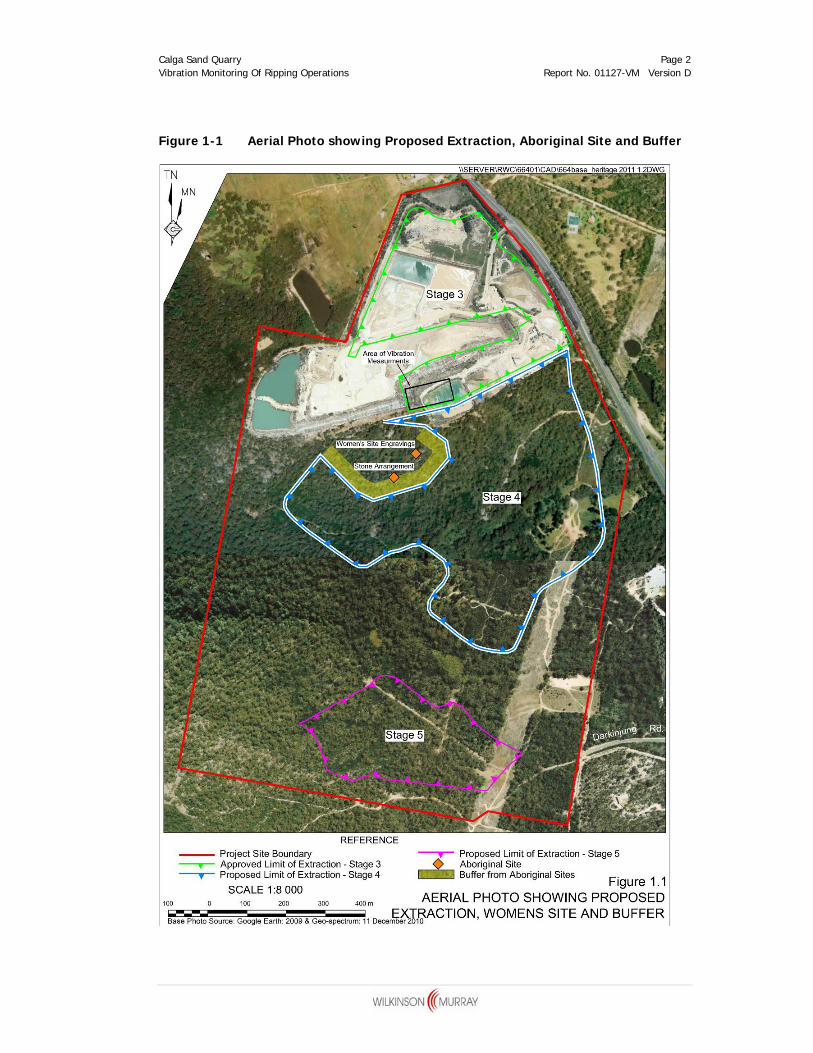
Rocla Materials Pty Limited (Rocla) is seeking approval to extend the existing operations at the Calga Sand Quarry into an adjoining area referred to as Stages 4 and 5 of the proposed Southern Extension (Refer Figure 1-1). A site of Aboriginal importance which includes rock engravings in the sandstone is located adjacent to the proposed Stage 4 extraction. We understand that this site has been described as “a women’s site” and so we have not been able to inspect the rock engravings.
Because of the significance of this site, Rocla has opted to provide a buffer of at least 40m between the site and the closest point of proposed sand extraction. Concerns have been raised by interested Aboriginal Stakeholders in relation to the potential for vibration damage to the engravings as a result of ripping within the quarry, even allowing for the proposed buffer. Ripping sandstone with a bulldozer would create the greatest level of vibration within the quarry.
This report presents an assessment of the likely risk of vibration damage to the rock engravings as a result of normal quarry ripping operations. This included a review of appropriate criteria and on site measurements of existing ripping operations.
Calga Sand Quarry Page 2 Vibration Monitoring Of Ripping Operations Report No. 01127-VM Version D
Figure 1-1 Aerial Photo showing Proposed Extraction, Aboriginal Site and Buffer
Calga Sand Quarry Page 3 Vibration Monitoring Of Ripping Operations Report No. 01127-VM Version D
2 MEASUREMENT PROCEDURE
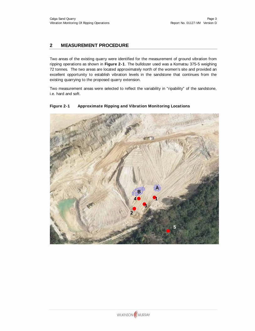
Two areas of the existing quarry were identified for the measurement of ground vibration from ripping operations as shown in Figure 2-1. The bulldozer used was a Komatsu 375-5 weighing 72 tonnes. The two areas are located approximately north of the women’s site and provided an excellent opportunity to establish vibration levels in the sandstone that continues from the existing quarrying to the proposed quarry extension.
Two measurement areas were selected to reflect the variability in “ripability” of the sandstone, i.e. hard and soft.
Figure 2-1 Approximate Ripping and Vibration Monitoring Locations
5
AB
1
23
4
Calga Sand Quarry Page 4 Vibration Monitoring Of Ripping Operations Report No. 01127-VM Version D
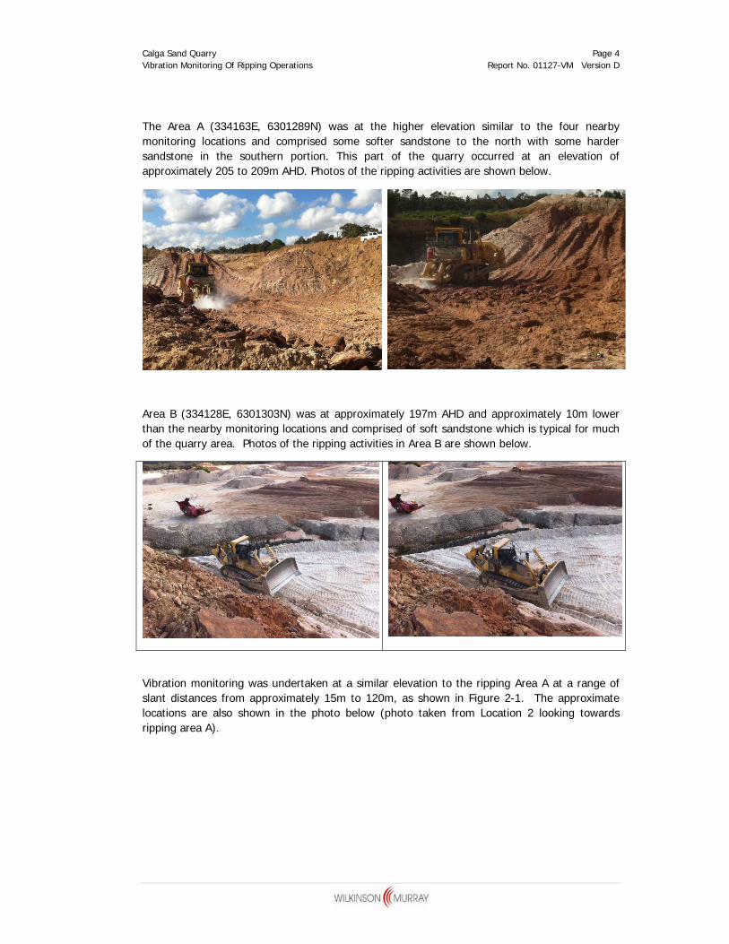
The Area A (334163E, 6301289N) was at the higher elevation similar to the four nearby monitoring locations and comprised some softer sandstone to the north with some harder sandstone in the southern portion. This part of the quarry occurred at an elevation of approximately 205 to 209m AHD. Photos of the ripping activities are shown below.
Area B (334128E, 6301303N) was at approximately 197m AHD and approximately 10m lower than the nearby monitoring locations and comprised of soft sandstone which is typical for much of the quarry area. Photos of the ripping activities in Area B are shown below.
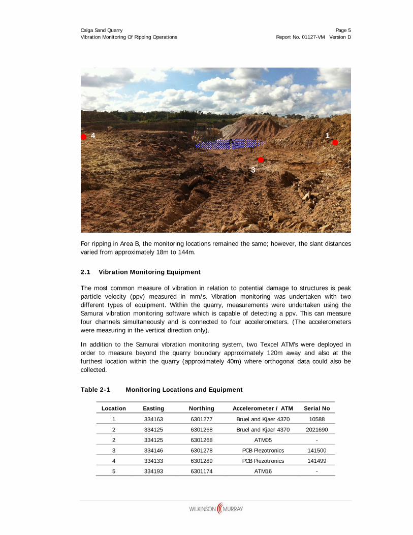
Vibration monitoring was undertaken at a similar elevation to the ripping Area A at a range of slant distances from approximately 15m to 120m, as shown in Figure 2-1. The approximate locations are also shown in the photo below (photo taken from Location 2 looking towards ripping area A).
Calga Sand Quarry Page 5 Vibration Monitoring Of Ripping Operations Report No. 01127-VM Version D
For ripping in Area B, the monitoring locations remained the same; however, the slant distances varied from approximately 18m to 144m.
2.1 Vibration Monitoring Equipment
The most common measure of vibration in relation to potential damage to structures is peak particle velocity (ppv) measured in mm/s. Vibration monitoring was undertaken with two different types of equipment. Within the quarry, measurements were undertaken using the Samurai vibration monitoring software which is capable of detecting a ppv. This can measure four channels simultaneously and is connected to four accelerometers. (The accelerometers were measuring in the vertical direction only).
In addition to the Samurai vibration monitoring system, two Texcel ATM’s were deployed in order to measure beyond the quarry boundary approximately 120m away and also at the furthest location within the quarry (approximately 40m) where orthogonal data could also be collected.
Table 2-1 Monitoring Locations and Equipment
Location Easting Northing Accelerometer / ATM Serial No
1 334163 6301277 Bruel and Kjaer 4370 10588
2 334125 6301268 Bruel and Kjaer 4370 2021690
2 334125 6301268 ATM05 -
3 334146 6301278 PCB Piezotronics 141500
4 334133 6301289 PCB Piezotronics 141499
5 334193 6301174 ATM16 -
1
3
4 A
Calga Sand Quarry Page 6 Vibration Monitoring Of Ripping Operations Report No. 01127-VM Version D
2.2 Measurement Results
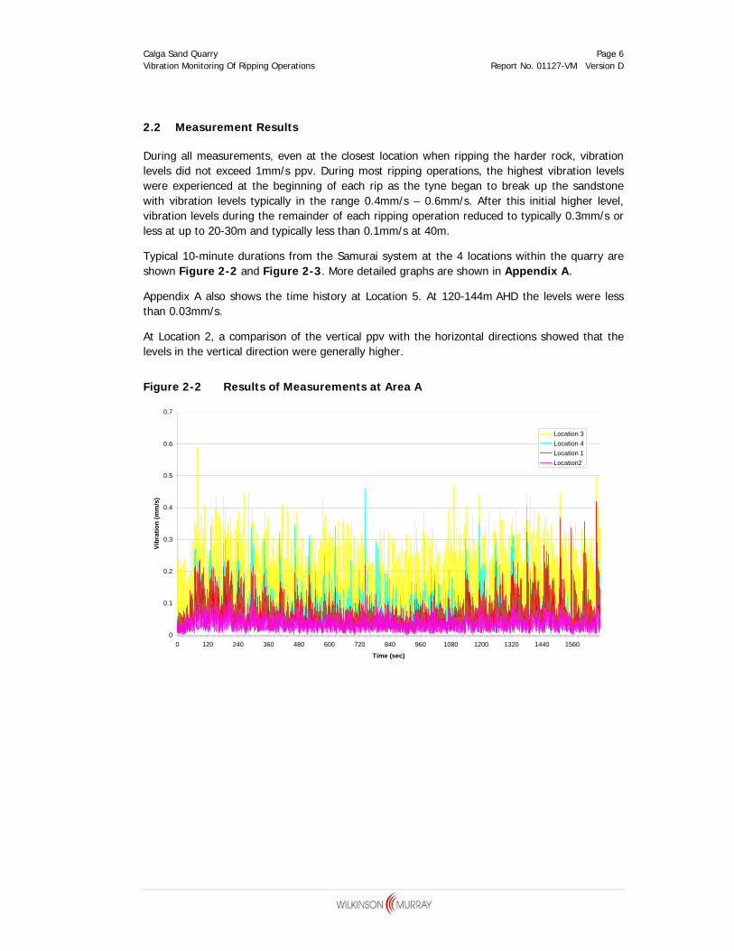
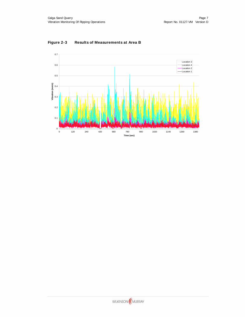
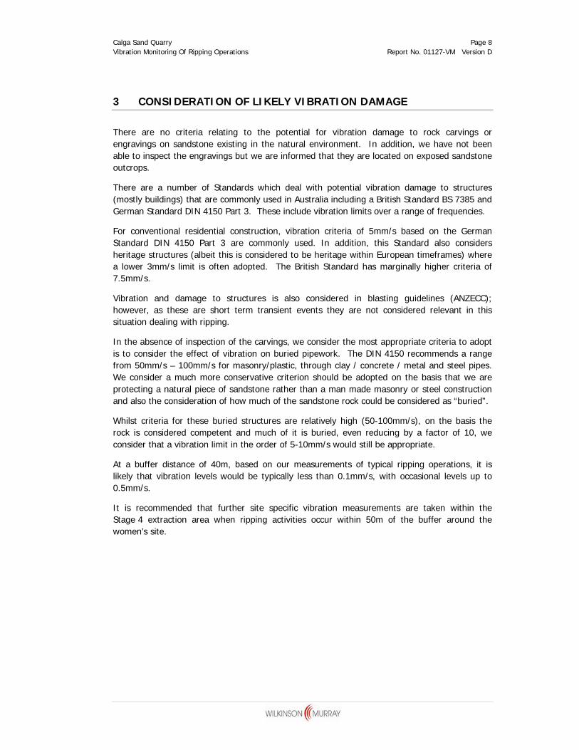
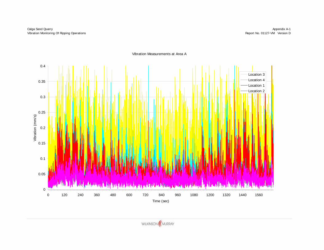
During all measurements, even at the closest location when ripping the harder rock, vibration levels did not exceed 1mm/s ppv. During most ripping operations, the highest vibration levels were experienced at the beginning of each rip as the tyne began to break up the sandstone with vibration levels typically in the range 0.4mm/s – 0.6mm/s. After this initial higher level, vibration levels during the remainder of each ripping operation reduced to typically 0.3mm/s or less at up to 20-30m and typically less than 0.1mm/s at 40m.
Typical 10-minute durations from the Samurai system at the 4 locations within the quarry are shown Figure 2-2 and Figure 2-3. More detailed graphs are shown in Appendix A.
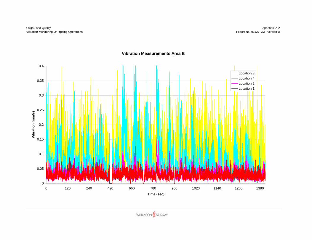
Appendix A also shows the time history at Location 5. At 120-144m AHD the levels were less than 0.03mm/s.
At Location 2, a comparison of the vertical ppv with the horizontal directions showed that the levels in the vertical direction were generally higher.
Calga Sand Quarry Page 7 Vibration Monitoring Of Ripping Operations Report No. 01127-VM Version D
Figure 2-3 Results of Measurements at Area B
0
0.1
0.2
0.3
0.4
0.5
0.6
0.7
0 120 240 420 660 780 900 1020 1140 1260 1380
Time (sec)
Vibr
atio
n (m
m/s
)
Location 3Location 4Location 2Location 1
Calga Sand Quarry Page 8 Vibration Monitoring Of Ripping Operations Report No. 01127-VM Version D
3 CONSIDERATION OF LIKELY VIBRATION DAMAGE
There are no criteria relating to the potential for vibration damage to rock carvings or engravings on sandstone existing in the natural environment. In addition, we have not been able to inspect the engravings but we are informed that they are located on exposed sandstone outcrops.
There are a number of Standards which deal with potential vibration damage to structures (mostly buildings) that are commonly used in Australia including a British Standard BS 7385 and German Standard DIN 4150 Part 3. These include vibration limits over a range of frequencies.
For conventional residential construction, vibration criteria of 5mm/s based on the German Standard DIN 4150 Part 3 are commonly used. In addition, this Standard also considers heritage structures (albeit this is considered to be heritage within European timeframes) where a lower 3mm/s limit is often adopted. The British Standard has marginally higher criteria of 7.5mm/s.
Vibration and damage to structures is also considered in blasting guidelines (ANZECC); however, as these are short term transient events they are not considered relevant in this situation dealing with ripping.
In the absence of inspection of the carvings, we consider the most appropriate criteria to adopt is to consider the effect of vibration on buried pipework. The DIN 4150 recommends a range from 50mm/s – 100mm/s for masonry/plastic, through clay / concrete / metal and steel pipes. We consider a much more conservative criterion should be adopted on the basis that we are protecting a natural piece of sandstone rather than a man made masonry or steel construction and also the consideration of how much of the sandstone rock could be considered as “buried”.
Whilst criteria for these buried structures are relatively high (50-100mm/s), on the basis the rock is considered competent and much of it is buried, even reducing by a factor of 10, we consider that a vibration limit in the order of 5-10mm/s would still be appropriate.
At a buffer distance of 40m, based on our measurements of typical ripping operations, it is likely that vibration levels would be typically less than 0.1mm/s, with occasional levels up to 0.5mm/s.
It is recommended that further site specific vibration measurements are taken within the Stage 4 extraction area when ripping activities occur within 50m of the buffer around the women’s site.
APPENDIX A VIBRATION MEASUREMENT RESULTS
Calga Sand Quarry Appendix A-1 Vibration Monitoring Of Ripping Operations Report No. 01127-VM Version D