Attachment D-4 Operable Unit 7-13/14 Feasibility Study Cost Estimate for the In Situ Vitrification Alternative The information in this cost estimate summary table is based on the best available information regarding the anticipated scope of the remedial alternative. Changes in the cost estimate are likely to occur as a result of new information and data collected during the engineering design, safety reviews, and remedial alternative. Major changes may be documented in the form of a memorandum in the administrative record$le, an explanation of signijicant differences, or a ROD amendment. This is an order-of- magnitude engineering cost estimate that is expected to be within -30 to +50percent of the actual project cost. D-73
Transcript
Attachment D-4
Operable Unit 7-13/14 Feasibility Study Cost Estimate for the In Situ Vitrification Alternative
The information in this cost estimate summary table is based on the best available information regarding the anticipated scope of the remedial alternative. Changes in the cost estimate are likely to occur as a result of new information and data collected during the engineering design, safety reviews, and remedial alternative. Major changes may be documented in the form of a memorandum in the administrative record$le, an explanation of signijicant differences, or a ROD amendment. This is an order-of- magnitude engineering cost estimate that is expected to be within -30 to +50percent of the actual project cost.
D-73
D-74
OPERABLE UNIT 7-13/14 FEASIBILITY STUDY COST ESTIMATE FOR THE IN SITU VITRIFICATION ALTERNATIVE
Project Title: Estimator: Brian K. Corb Date: December 2002 Estimate Type: Planning Reviewed/Appr.: Lee LindigBruce L. Stevens
WAG 7 OU 13/14 Feasibility Study
I. SCOPE OF WORK:
A. Remedial Design and Remedial Action
The ISV alternative will remove and destroy the organic constituents of the waste and encapsulate most of the inorganic constituents within a durable glass-like monolith. This stable waste form will reduce the potential for the migration of hazardous constituents to adjacent media. Work associated with construction of the ISV alternative includes preconstruction activities, restaging Pad A waste, placing additional soil over areas to reduce the potential for melt expulsion events, preconditioning waste by ISTD, ISV of selected waste disposal areas, collecting and treating off-gases, conducting ISG of selected waste disposal areas, and constructing a Modified RCRA Subtitle C cover system over the SDA. Preconstruction activities will include investigating borrow sources; testing ISTD, ISV, and ISG technology; remedial design; personnel training; completion of a readiness assessment; and mobilization. Waste materials will be removed from Pad A and relocated into an adjacent pit for treatment by the ISV process. Additional soil will be added to areas of the SDA to provide a minimum soil thickness of 10 ft over areas before ISTD and ISV.
ISTD will be completed on waste areas before beginning treatment with ISV. ISTD will dry out the soil and waste sludge, vaporize volatile materials, and safely breach most remaining sealed containers. Underburden soil also will be heated using ISTD to remove interstitial water and any water perched on the underlying basalt. A starter path for ISV will be installed beneath the soil cover and a large massive hood will be placed over the melt area to contain off-gases. Electrical current will be passed through the starter path to begin melting waste and soil. The melt will sink into the waste materials and create a melt zone from the surface of the waste to the basalt layer. An off-gas treatment system will collect and treat gases generated during the ISTD and ISV process.
The ISG will be performed on areas that cannot be treated with ISV. These areas will include the SVRs and other areas of waste that contain elevated levels of activated metals. Other areas of the SDA not treated with ISV or ISG will undergo foundation stabilization grouting to minimize subsidence. Following completion of ISTD and ISV and grouting activities, the SDA surface will be graded and a modified RCRA Subtitle C cover system will be installed. The cover system will include an infiltration barrier and erosion controls to minimize seepage into the treated waste and prevent intrusion by burrowing animals and plant roots.
B. Long-Term Monitoring and Maintenance
After the Remedial Action has been completed, long-term monitoring and maintenance will continue for a 100-year window. The long-term environmental monitoring will be conducted for groundwater, vadose zone water, surface water, and air. CERCLA reviews will be conducted every 5 years. The cover system will be monitored annually during the first 5 years following completion of construction (beginning after the vegetation establishment period). After the completion of annual monitoring, the monitoring
D-75
OPERABLE UNIT 7-13/14 FEASIBILITY STUDY COST ESTIMATE FOR THE IN SITU VITRIFICATION ALTERNATIVE
(continued).
Proiect Title: WAG 7 OU 13/14 Feasibilitv Studv
frequency will be reduced to every 5 years concurrent with the 5-year reviews required under CERCLA. The cover system will be monitored for vegetation density, erosion damage, and differential settlement. Areas of erosion damage will be repaired with additional topsoil or earth fill, and reseeded. Areas without vegetation will be reseeded.
11. BASIS OF ESTIMATE:
The basis of the estimate was developed from the following sources to provide a defensible and comparative cost of the remedial alternatives. The applicable sources available for the ISV alternative include:
A.
A. 1
A.2
A. 3
A.4
A. 5
A. 6
A. 7
A. 8
A. 9
A.10
A. l l
A.12
A.13
EPA 540-R-00-002, “A Guide to Developing and Documenting Cost Estimates During Feasibility Study,” July 2000
INEEL, “Cost Estimating Guide,” DOE/ID-10473, September 2000
“Environmental Assessment and Plan for New Silt/Clay Source Development and Use at the Idaho National Engineering and Environmental Laboratory, DOEEA-1083,” May 1997
Caterpillar EquQment Performance Handbook, 3 1 st Edition
The INEEL Site Stabilization Agreement, Union Labor Agreement
Facilities Unit Costs-Military Construction, PAX Newsletter No. 3.2.2-1 0, 2000
ICDF Construction Cost Estimate, Cap Construction Cost (CH2MHILL, December 2000)
Subject Matter Experts-M. Jackson, BBWI, and T. Borsches. BBWI, “Availability of Borrow Source Material at the INEEL”
BBWI, “INEEL Site Craft and Professional Services Labor Rates,” February 2002
OMB, 2002, “Guidelines and Discount Rates for Benefit-Cost Analysis of Federal Programs,” Appendix C, “Discount Rates for Cost-Effectiveness, Lease Purchase, and Related Analyses,” OMB Circular A-94, February 2002.
R. S. Means, 2002, Heavy Construction and Industrial Building Unit Costs Data 16” edition, Kingston, Massachusetts.
INEEL, “Analytical Laboratory Unit Costs.”
D-76
OPERABLE UNIT 7-13/14 FEASIBILITY STUDY COST ESTIMATE FOR THE IN SITU VITRIFICATION ALTERNATIVE
(continued).
Proiect Title: WAG 7 OU 13/14 Feasibilitv Studv
111. ASSUMPTIONS:
The primary work associated with the ISV alternative includes ISTD and ISV and grouting of waste materials, and placing a Modified RCRA Subtitle C cover system over the SDA. Specific elements of the work and important assumptions are provided below:
A. Management and Oversight
A. 1 Project Management for the BBWI oversight of this alternative has been estimated based on an average classification of job categories using the BBWI rates. The number of FTEs are based on 2,000 MH per person per year.
A.2 The RD/RA schedule assumes that the budgetary funding will not be constrained.
A.3 The RD/RA schedule assumes that no unexpected delays will result from changes to the USQ/SAR process.
A.4 The estimate assumes that the INEEL site resources (i.e., CFA, medical facilities, geotechnical lab, fire department, security, utilities at the SDA) will be available for the duration of the project.
B. Design and Preconstruction
B. 1 Site review-Additional site characterization and analysis of records will be completed to identify waste disposal areas of the SDA that might contain excessive levels of combustible and alkaline materials and inadequate soil. Records also will be reviewed for the possible presence of spent fuel and high radiation sources within waste disposal areas.
B.2 Treatability testing-Because this alternative employs ISV and ISTD technologies in unproven applications, a significant amount of testing of the technologies will be needed. Testing will include cold ISV and ISTD testing, cold integrated ISTD and ISV testing, and hot integrated ISTD and ISV testing. Cold testing also will be needed for ISG and foundation stabilization grouting.
B.3 Preconstruction activities-Preconstruction activities will include borrow source investigations, cultural resource clearance, developing an onsite source of basalt rock, final design, readiness assessment completion, and mobilization.
C. Pad A Waste Restaging
C.l Pad A waste will be restaged by moving waste to a new pit adjacent to the pad while adding more soil to ensure a mixture suitable for vitrification. The waste will be restaged with an equal volume of soil in a 150- x 240- x 25-ft deep pit (900,000 ft’) constructed adjacent to Pad A. Contaminated overburden, underburden, and berm soil will be used as the source of soil to mix with the waste.
D-77
OPERABLE UNIT 7-13/14 FEASIBILITY STUDY COST ESTIMATE FOR THE IN SITU VITRIFICATION ALTERNATIVE
(continued).
Proiect Title: WAG 7 OU 13/14 Feasibilitv Studv
c.2 A restaging building will be constructed that encompasses Pad A and the new disposal pit. The building will be approximately 300 x 300 ft with heights of 35 ft above Pad A and 25 ft above the new disposal pit. Remotely operated bridge cranes equipped with clam shovels will be installed in the building and used to move waste and soil from Pad A to the pit. Transfer carts will be used to move waste in bins from Pad A to the pit area. The building will be constructed to Seismic Category I1 requirements, to provide seismic stability during restaging activities. Water fogs will be employed to minimize airborne particulates. The building will be maintained under a negative pressure of about -4-in.water gauge to ensure containment of airborne contamination. The air in the building will be exhausted through HEPA filters and a stack after heating the air to above its dew point temperature. Two 100% blowers will provide the motive force for exhausting the facility. A separate diesel-powered blower will provide ventilation in case line power is lost.
C.3 A waste and soil mixture will fill the pit to within 5 ft of the top of the pit. A 5-ft layer of clean soil will be placed on top of the waste and soil mixture before decontaminating and removing the building in which restaging activities are conducted.
D. Placement of Additional Soil
D. 1
D.2
D.3
D.4
D.5
Additional soil will be placed on top of all designated pits and trenches designated for ISTD and ISV to meet the objective of 10 ft of soil covering zones undergoing vitrification. Specific groupings of pits and trenches under the same soil and ballast cover will include all designated trenches and Pits 1 and 2; Pit 3; Pits 4, 6, 10, 11, and 12; Pit 5; Pit 9; and the new Pad A pit.
It is assumed that approximately 5 ft of soil covers the waste sites at present. A total of 12 ft of soil will be needed to allow for safe emplacement of ISV starter path material between electrodes at a depth of 10 ft. This will ensure a 2-ft buffer of clean soil above the waste level.
It is assumed that the surface area for Pits 1, 2, 3,4, 5 , 6, 9, 10, 11, and 12 totals 663,974 ft3 and the surface area for Trenches 1 through 10 totals 86,555 ft3.
Soil must support the heavy equipment used during ISV. Local soils contain sufficient clay to render the soil unsuitable for road use under rainy conditions. Therefore 7 ft of additional soil cover will be required. The upper 3 ft of soil will consist of a suitable road ballast material, compacted to meet vehicle load-bearing requirements. This fresh ballast material will need to be transported from an off-Site location, with an average transport distance of 30 to 40 mi. Total volume of off-Site ballast material needed is 170,000 yd3.
A 4-ft soil layer placed below the ballast will provide the remaining soil height to satisfy the 12-ft cover objective. This 4-ft soil layer will consist of onsite soil with a total volume of 160,000 yd3.
D-78
OPERABLE UNIT 7-13/14 FEASIBILITY STUDY COST ESTIMATE FOR THE IN SITU VITRIFICATION ALTERNATIVE
(continued).
Proiect Title: WAG 7 OU 13/14 Feasibilitv Studv
D.6 The soil and ballast cover will be flat and extend 20 ft beyond the footprints of the trenches and pits. The soil/ballast cover will span the entire area that contains the designated trenches because the spacing between trenches averages only 20 ft. Contiguous pits will be combined under the same soil and ballast cover to facilitate movement of ISTD and ISV equipment.
D.7 Soil and ballast cover on waste area groupings will be encircled by bermed soil installed at a 3:l slope. Berms will be 7 ft high with bases extending 21 ft beyond the edge of the cover.
D.8 The total quantity of soil to be used in the cover and berm is approximately 250,000 yd3. Soil and ballast will cover a total area of about 32 acres, not including the area covered by the berms.
E. Other Site Preparation and Support Activities/Facilities
E. 1
E.2
E.3
E.4
E.5
E.6
E.7
Personnel training-Before beginning construction operations, site personnel will be trained in the startup and operation of equipment related to ISTD, ISV, ISG, and foundation stabilization grouting technologies.
A 10,000 ft2 secondary waste treatment building will be installed that includes an activated carbon recycling system, a mercury recovery and treatment system, a grout mixing and pumping system, a sludge filtration and thermal treatment system, and a treated secondary waste packaging system.
A tank system will be installed that includes a sodium hydroxide receipt tank, a diluted sodium hydroxide storage tank, a spent scrubber solution receipt tank, two treated scrubber solution storage tanks, an anhydrous ammonia storage tank, and a grout solids hopper.
A maintenance building and decontamination pad will be installed for servicing vehicles.
Two trailers will be installed. One trailer will contain offices and a lunchroom, and the other trailer will contain a change room and personnel survey and decontamination capability.
A 2,000,000-gal capacity grout disposal basin lined and covered with HDPE geomembrane will be provided.
During development of this cost estimate, modular containment buildings were evaluated including Butler and Sprung structures. Typically, the Sprung structure erected on a perimeter foundation is not designed for double-containment and live loads such as a bridge crane. Therefore, the cost provided for those sites to be treated by ISG considers a Sprung-type containment structure for waste grouting operations; no containment structure is assumed to be required for foundation stabilization grouting operations. The costs for these facilities include fire protection, HVAC, lighting, communication lines, and power distribution.
D-79
OPERABLE UNIT 7-13/14 FEASIBILITY STUDY COST ESTIMATE FOR THE IN SITU VITRIFICATION ALTERNATIVE
(continued).
Proiect Title: WAG 7 OU 13/14 Feasibilitv Studv
F. Preconditioning Waste with ISTD
F. 1
F.2
F.3
F.4
F.5
F.6
F.7
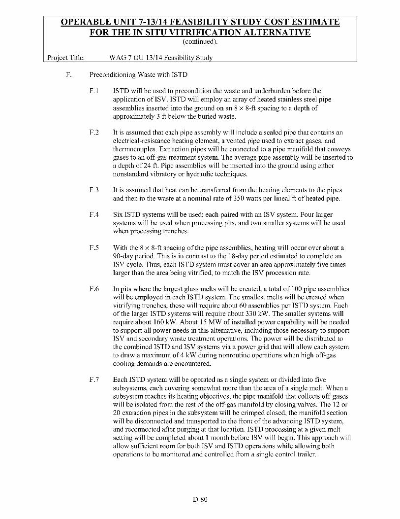
ISTD will be used to precondition the waste and underburden before the application of ISV. ISTD will employ an array of heated stainless steel pipe assemblies inserted into the ground on an 8 x 8-ft spacing to a depth of approximately 3 ft below the buried waste.
It is assumed that each pipe assembly will include a sealed pipe that contains an electrical-resistance heating element, a vented pipe used to extract gases, and thermocouples. Extraction pipes will be connected to a pipe manifold that conveys gases to an off-gas treatment system. The average pipe assembly will be inserted to a depth of 24 ft. Pipe assemblies will be inserted into the ground using either nonstandard vibratory or hydraulic techniques.
It is assumed that heat can be transferred from the heating elements to the pipes and then to the waste at a nominal rate of 350 watts per lineal ft of heated pipe.
Six ISTD systems will be used; each paired with an ISV system. Four larger systems will be used when processing pits, and two smaller systems will be used when processing trenches.
With the 8 x 8-ft spacing of the pipe assemblies, heating will occur over about a 90-day period. This is in contrast to the 1 &day period estimated to complete an ISV cycle. Thus, each ISTD system must cover an area approximately five times larger than the area being vitrified, to match the ISV procession rate.
In pits where the largest glass melts will be created, a total of 100 pipe assemblies will be employed in each ISTD system. The smallest melts will be created when vitrifying trenches; these will require about 60 assemblies per ISTD system. Each of the larger ISTD systems will require about 330 kW. The smaller systems will require about 160 kW. About 15 MW of installed power capability will be needed to support all power needs in this alternative, including those necessary to support ISV and secondary waste treatment operations. The power will be distributed to the combined ISTD and ISV systems via a power grid that will allow each system to draw a maximum of 4 kW during nonroutine operations when high off-gas cooling demands are encountered.
Each ISTD system will be operated as a single system or divided into five subsystems, each covering somewhat more than the area of a single melt. When a subsystem reaches its heating objectives, the pipe manifold that collects off-gases will be isolated from the rest of the off-gas manifold by closing valves. The 12 or 20 extraction pipes in the subsystem will be crimped closed, the manifold section will be disconnected and transported to the front of the advancing ISTD system, and reconnected after purging at that location. ISTD processing at a given melt setting will be completed about 1 month before ISV will begin. This approach will allow sufficient room for both ISV and ISTD operations while allowing both operations to be monitored and controlled from a single control trailer.
D-80
OPERABLE UNIT 7-13/14 FEASIBILITY STUDY COST ESTIMATE FOR THE IN SITU VITRIFICATION ALTERNATIVE
(continued).
Proiect Title: WAG 7 OU 13/14 Feasibilitv Studv
G. ISV Assumptions
G. 1
G.2
G.3
G.4
G. 5
G. 6
ISV will be used to raise the temperature of the ISTD-treated waste further to about 1,500"C to convert it to a glassy monolith. ISV will complete the pyrolysis and decomposition of the waste constituents initiated by ISTD, and then vitrify the waste and associated soils. The ISV process will heat soil and waste in the designated pits and trenches by passing current through the materials using four, 12-in. diameter graphite electrodes inserted into the ground.
Electrodes used to vitrify pit waste will be installed in a square array on about an 1 1 -ft spacing. This configuration will create generally circular melts averaging 35 ft in diameter. Electrodes used to vitrify trench waste will be installed in a line 1 1 ft apart. This configuration will create rectangular-shaped melts averaging approximately 3 5 4 long x 15-ft wide. If necessary, power will be applied between the center electrodes to achieve the desired melt width between the two planar melts.
When first applying voltage to the electrodes in the ISV process, a flow of electrical current will be established through an electrically conductive, buried starter path containing powdered graphite and glass frit. The resultant discharge of joule heat in the starter path will raise the starter-path temperatures to as high as 2,OOO"C. This temperature is well above the temperature required to melt soil (about 1,lOO"C to 1,400"C). As the starter path melts, soil immediately adjacent to the starter path will begin to melt and mix with the molten frit.
The starter path will be created using a backhoe to excavate trenches 2-ft wide x IO-ft deep (i.e., 2 ft above the buried waste level). A I-ft deep layer of the starter path material will be placed in each trench, followed by four, 2-ft diameter x 10-ft long steel tubes inserted vertically on 1 1 -ft centers. The trenches will be backfilled with the excavated soil. The tubes will provide holes for guiding the electrodes to the desired starting elevation. Approximately 6 in. of electrically conductive grease will be added to the base of each tube if necessary to ensure adequate electrode-to- starter path conductivity. Thermocouples embedded in the waste at varying diameters will provide the capability to monitor the progression of the melt.
Densification of the waste and soils will occur because the glass usually contains few voids, and because the oxidation and pyrolysis that occur during melting largely eliminate organic materials. A 60% volume reduction is expected in the designated pits and trenches at the SDA. The melts will average about 6 ft in height. The average depth of the base of a completed melt below the soil-cover surface will be about 24 ft.
Each melt setting will consume on average about 100,000 kW-h based on an estimated power consumption rate of 300 kW-h per ton of glass produced. The estimated time to provide power to a melt is 8 days, requiring the delivery of 700 kW power to the pit electrodes and 350 kW to the trench electrodes.
D-8 1
OPERABLE UNIT 7-13/14 FEASIBILITY STUDY COST ESTIMATE FOR THE IN SITU VITRIFICATION ALTERNATIVE
(continued).
Proiect Title: WAG 7 OU 13/14 Feasibilitv Studv
G.7 Surface area of the melts will overlap each other by 15%, and the melts will overlap to the soil that bounds the trenches and pits by 6 ft on average to ensure effective vitrification of contaminated areas. A total of 1,300 melts will be required over a 15-year operating period, requiring four pit-ISV systems and two trench- ISV systems operating on an 1 &day melt-to-melt cycle at 70% total operating efficiency.
G.8 Gases produced at each ISV setting will be vented to a 70-ft-diameter off-gas hood centered over each melt zone. The hood will be substantially more robust than hoods used in earlier ISV applications to resist the highly corrosive effects of the melt off-gases and ensure effective containment of respirable TRU contaminants that may be emitted into the hood. The hood will be hydraulically jacked 1 ft above the ground using an external frame and then driven 32 ft to the next melt setting where it will be lowered to the ground. A 60-ft boom crane with a 5-ton capacity will be used to raise and move a hopper of dry sand around the boundary of the hood.
G.9 The hood will be equipped with remote grapples to accept new electrode segments, screw them into position on the electrodes, and then lower the electrodes into the tube guides installed on the starter paths. The crane must lift and transfer 12 to 16 electrode segments to the grapple positions during each &day ISV power-on cycle. A crane will be dedicated to each of the six ISTD and ISV systems.
G. 10 Each hood will be equipped with nine hydraulic rams capable of breaking down bridges of soil that may form over the melts as the waste undergoes volume reduction during melting. The rams will be equipped with a cyclone and star valve to aid in the receipt and delivery of washed, dry sand to the hood. Dry sand will be pneumatically delivered from a 20-yd3 hopper truck each day to the cyclones and fed down the hollow center of the rams into the enclosed space of the hood. The addition of sand to the hood will compensate for the average 10 ft of subsidence expected during vitrification and ensure that the waste area will not become exposed to air. Approximately 7 ft of sand will be added to the subsidence zone, leaving 3 ft to be filled with road ballast after the hood is moved to the next location. Approximately 300,000 yd3 of sand will be delivered and placed to seal hoods to the ground and compensate for subsidence. Approximately 100,000 yd3 of ballast will be delivered and placed to restore the load-bearing capability of the site to support future traffic. Approximately five 20-yd3 truckloads of sand and ballast will be delivered each day to the six locations undergoing ISV.
H. Treatment of Off-Gases Generated During In situ Thermal Desorbtion and In Situ Vitrification
H. 1 Separate off-gas treatment systems will be used to treat off-gases generated by the paired ISTD and ISV systems. The conceptual ISTD off-gas system will include traps to condense and collect elemental mercury as the off-gas exits the gas extraction pipes. Other trap locations also may be needed in the off-gas collection manifold to minimize corrosive damage to the piping. The gas will then pass through a roughing filter and a metal HEPA filter designed to stop further
D-82
OPERABLE UNIT 7-13/14 FEASIBILITY STUDY COST ESTIMATE FOR THE IN SITU VITRIFICATION ALTERNATIVE
(continued).
Proiect Title: WAG 7 OU 13/14 Feasibilitv Studv
H.2
H.3
H.4
H.5
H.6
entrainment of any TRU-contaminated particles that may be present. After filtration, the still hot gases will be chilled to about 50°C to condense and collect both water and mercury in a wet scrubber and demister. Elemental mercury will be collected in traps and the condensed water will be passed through two activated carbon filters in series to remove organics and mercury in the +2 valence state.
The water then will be neutralized with sodium hydroxide and evaporated to a salt concentration of about three molar using primarily waste heat generated by the off- gas system. The concentrated salt solution will be transported in 1,000 gal tanker trucks to a secondary waste treatment facility for further processing. One tanker truck will be transported every 5 days to the secondary waste treatment facility. Approximately 200,000 gal of 19-molar sodium hydroxide will be needed in ISTD and ISV off-gas neutralization processes during the 15 years of operation. Two 5,000-gal steel tanks will be needed; one a heated tank for receipt of 19-molar sodium hydroxide and one for dilute neutralization feed makeup. Both tanks will be installed in a lined, bermed basin for protection in the event of a leak.
The acidic off-gases will be treated in a thermal oxidation unit using natural gas as the heat source (when required) and controlled air feed as the oxygen source. The resulting gas will be cooled and then passed through two activated carbon adsorbers in series to remove mercury +2 and residual organic carbon. The acidic gases then will be passed through a bag house or two static lime-based dry scrubbers in series to remove acid halogens, sulfuric acid, and residual carbon monoxide before being drawn into a blower. The blower will impel the gas forward to a selective catalyzed reactor where anhydrous ammonia will be injected to chemically reduce the nitrogen oxides to nitrogen gas. Approximately 200,000 gal of anhydrous ammonia will be consumed over the 15-year processing period. A tanker truck will deliver ammonia to each of the six systems every few weeks. The fully treated gases will be discharged to the atmosphere via a stack.
The ISTD off-gas system will include two identical trains; both designed for 100% capacity at about 100 ft3/minute. Adsorber vessels will be mounted on skids. Both trains will operate simultaneously, but one in a standby mode to ensure readiness of the other train failed. The off-gas treatment process will be controlled from the same trailer used to control thermal desorption, ISV, and the ISV off-gas treatment process. Two diesel generators designed to withstand the design-basis earthquake will provide emergency power to the blowers to ensure continued ventilation of the off-gas system if line power were lost.
The ISV off-gas system will be similar to the ISTD system. The major exception is its much larger size, nearly 100 times the capacity of the ISTD system to accommodate the dilution air added at the hood.
The ISV off-gas train will begin with a roughing filter and HEPA filter, followed by quencher and wet scrubber with a mercury trap and solids filter. Water recirculated through the scrubber will be neutralized with sodium hydroxide to scrub acids from the off-gases. The scrub solution will be evaporated using primarily waste heat and then trucked to the secondary waste treatment facility for
D-83
OPERABLE UNIT 7-13/14 FEASIBILITY STUDY COST ESTIMATE FOR THE IN SITU VITRIFICATION ALTERNATIVE
(continued).
Proiect Title: WAG 7 OU 13/14 Feasibilitv Studv
further processing. The scrubbed off-gases will be heated to about 1 10°C and passed through banks of activated carbon adsorbers to remove trace organics and mercury. The fully treated gas will be drawn through two 100%-capacity blowers and discharged to the atmosphere via a stack.
H.7 Like the ISTD system, the ISV system will include two identical trains that will fit onto a single trailer (with the exception of the adsorber vessels). The redundant ventilation systems provided for each ISV system will be necessary to ensure effective containment of airborne contaminants while diluting the gas under the hood with air to prevent potential buildup of explosive concentrations. Each of the redundant off-gas treatment trains will be capable of drawing and treating about 3,000 ft3/min of gas. An emergency backup ventilation system powered with emergency diesel generators would be necessary if a large earthquake were to sever the duct connections between the hoods and off-gas trailers.
I. Secondary Waste Treatment
I. 1 Secondary waste generated during ISTD and ISV operations will include flasks of elemental mercury, vessels containing saturated activated carbon and spent acid sorber materials, concentrated neutralized scrubber solutions, and failed equipment. Failed equipment will include spent roughing filters and HEPA filters, and corroded or plugged pipes and off-gas processing vessels. Failed equipment that may be contaminated with TRU materials will be treated and disposed of by placing it on top of one of the trenches purposely left uncovered. The failed equipment will then be covered with soil and ballast, and vitrified with the waste beneath it. A small fraction of the failed equipment, in particular the filters, may be classified as TRU waste. All remaining secondary waste will be classified as either low-level waste (LLW) or mixed low-level waste (MLLW).
1.2 Concentrated scrubber solutions will be transported in 1,000-gal batches and pumped into an agitated 10,000-gal steel tank. The solution will then be filtered or centrifuged to remove sludge, which will likely contain mercury and other heavy metals requiring treatment. The sludge will be dried and retorted to drive off mercury, which will be condensed and further treated. The filtered scrubber solution will be collected in one of two other 10,000-gal tanks in preparation for grouting to immobilize the solution and heavy metals it may contain.
1.3 Grouting of the treated secondary liquid waste will be accomplished on an 8,000-gal batch basis once every 40 days. A dry grout blend consisting of Portland cement and clay will be mixed in a ratio of about 10 lbs of blend per gal of solution. The volume of the resulting grout slurry will be about 50% greater than the volume of the solution. The grout slurry will be pumped approximately 300 ft to a basin where it will flow to a low point and harden. The basin will be approximately 200-ft square at the surface, double-lined with HDPE, and be covered with floating HDPE. It will be designed to contain about 2 million gal of grout. The grout blend will be purchased premixed from a vendor, transported in 20-yd3 hopper trucks, and unloaded using pneumatics into a 50-yd3 grout-feed silo.
D-84
OPERABLE UNIT 7-13/14 FEASIBILITY STUDY COST ESTIMATE FOR THE IN SITU VITRIFICATION ALTERNATIVE
(continued).
Proiect Title: WAG 7 OU 13/14 Feasibilitv Studv
Approximately 6,000 tons of dry grout blend will be required over the 15-year- operating period.
1.4 Saturated activated carbon will be regenerated under elevated temperatures and chemically reducing conditions. This step will enable its reuse about 10 times by removing adsorbed mercury and organic compounds. The estimated quantity of spent activated carbon disposed of will be 1,000 55-gal drums. The spent carbon will be disposed of at the ICDF. The organic materials desorbed from the carbon will be destroyed in the vapor form in a small thermal oxidation unit. The desorbed mercury will be condensed and then amalgamated along with mercury collected in flasks during ISTD and ISV processing and with mercury condensed during retorting of scrubber sludge.
1.5 Mercury amalgamation will occur by combining and mixing the mercury with elemental sulfur, heating it, and then vigorously agitating the mixture to create the amalgam. Some of the scrubber sludge that resists retorting will be ground to a fine powder and amalgamated as well. Approximately 100 tons of sulfur will be needed in the amalgamation process. The estimated total quantity of amalgamated waste produced is 2,000 5-gal containers. Amalgamated waste will be disposed of at the ICDF.
1.6 Spent acid sorber material will be disposed of directly in its processing vessels at the ICDF. Approximately 500 500-gal vessels of spent acid sorber material will be disposed of.
1.7 The secondary waste disposal facility will be of metal-frame construction and also house a small laboratory for analyzing secondary waste and treated products. The maintenance and stores building will be located nearby, as will the office trailer and a worker change room trailer.
5. In Situ Grouting and Foundation Stabilization Grouting Assumptions
5. 1 The ISG technology will be used to grout SVRs and other areas of the site containing activation and fission product waste. Foundation stabilization grouting technology will be used to grout remaining untreated areas of the SDA to provide a stable foundation for the Modified RCRA Subtitle C cover system.
5.2 The grouting equipment and enclosures will be dismantled and disposed of under the cover system. Cost for dismantling and disposing of the grouting equipment is 25% of the operational costs of grouting.
5.3 Waste in SVRs and portions of waste trenches will be treated by ISG using jet grouting with specialized grout.
5.4 Wastes will be stabilized to reduce settlement (foundation stabilization grouting) by jet grouting areas of pits and trenches with cement-based grout. It is assumed that once the foundation stabilization grouting has been completed, heavy equipment operations can commence without any ground subsidence. No
D-85
OPERABLE UNIT 7-13/14 FEASIBILITY STUDY COST ESTIMATE FOR THE IN SITU VITRIFICATION ALTERNATIVE
(continued).
Proiect Title: WAG 7 OU 13/14 Feasibilitv Studv
additional costs for cribbing or temporary road stabilization are included in the estimate.
J.5 Grouting operations will be conducted within a weather enclosure to facilitate RadCon control. Two sprung-type structures will be mobilized to the site. These structures will be initially constructed and progressively disassembled and reconstructed as required to accommodate advancement of the ISG operation. Following completion of the grouting operation within an enclosure and before disassembly of the building, the grouted area will be covered with a minimum of two ft of earth fill.
J.6 The grout production rate can be maintained and no subsurface anomalies will adversely impact the assumed total operating efficiency of 70%. ISG will be performed using the same grouting technique and grout types as described for the ISG alternative; however, ISG will be limited to the SVRs and portions of the waste trenches. Detailed assumptions related to ISG are provided in the ISG alternative cost estimate.
5.7 The SVRs and non-TRU trench areas containing high activation and fission product concentrations will be treated using the ISG technology with grout injected on a 2-ft center-to-center spacing. One hole will be grouted every 4 minutes.
5.8 Foundation stabilization grouting will be achieved using low-pressure ISG technology with grout injected on a 4-ft center-to-center spacing. One hole will be grouted every 4 minutes.
J.9 Grouting for foundation stabilization will be performed using a modified drill rig to inject grout into the waste stream. The grout will fill readily accessible void spaces and cure into a solid monolith. This technique allows using a relatively low-cost, cement-based grout instead of the specialized grout types used for waste treatment. Unlike grouting for waste treatment, completely mixing grout with the waste or soil will not be required. Voids that could degrade integrity of the cover system are fairly large and will be filled sufficiently with grout to ensure adequate cover support. Substantially less grout will be needed for foundation stabilization because the grout will be injected on a less frequent spacing and because the waste was partially compacted when initially placed in the SDA. Detailed assumptions for foundation stabilization grouting for the cover system are addressed in the ISG alternative cost estimate.
J. 10 The equipment and crew sizes needed for ISG and foundation stabilization grouting are similar to those needed for the ISG alternative.
K. Borrow Areas for the Cover System
K. 1 Spreading Area B will be available and will not be flooded. No additional costs have been provided to dewater Spreading Area B.
D-86
OPERABLE UNIT 7-13/14 FEASIBILITY STUDY COST ESTIMATE FOR THE IN SITU VITRIFICATION ALTERNATIVE
(continued).
Proiect Title: WAG 7 OU 13/14 Feasibilitv Studv
K.2 The quantity and quality of borrow source material available from Spreading Area B, the Borax Pit, and the Basalt Source (for riprap and coarse fractured material) will be adequate. No royalty fees and special earthen material costs will apply.
K.3 An adequate water source will be available to support the requirements for earthmoving and soil moisture conditioning for placement and compaction.
L. Modified Resource Conservation and Recovery Act Subtitle C Cover System Construction
L. 1 Placement of earthen fill-An average 1 0-ft-thick layer of earthen fill will be placed over the surface of the SDA following ISTD and ISV and ISG. This will grade the surface to the top of the mounded soil covers placed over areas subjected to ISTD and ISV in preparation for placing the cover system.
L.2 A 6-in.-thick layer of processed gravel will be placed over the earthen fill to allow gases to safely vent that might build up beneath the cover system.
L.3 The earthen fill and the gravel gas venting layers of the cover system will be placed during grouting activities.
L.4 A 4-in. asphalt base course and a 6-in. low-permeability asphalt layer will be placed over the gas collection layer to function as infiltration barriers. A 6-in. lateral drainage layer consisting of processed sand will be placed over the asphalt to enable drainage of infiltration from the surface of the barrier layer. A 1 -ft-thick filter section consisting of sand and gravel will be placed over the lateral drainage layer.
L.5 Remaining cover system layers will consist of a 20-in. compacted topsoil layer and a 20-in. layer of mixed topsoil and gravel.
L.6 A 6-ft-high berm will be constructed around the perimeter of the cover system to control flooding; filter layers, coarse fractured basalt, and riprap will be placed on the side slopes to minimize erosion.
L.7 The topsoil layer will be seeded with a specialized seed mix to provide a vegetative cover. The cover will be monitored and reseeded as necessary to maintain the vegetative layer.
M. Treatability Testing Assumptions
M. 1 Additional characterization of the SDA and treatability testing using both simulated and actual waste locations will be required to establish the design and safety basis for operating ISV, ISTD, ISG, and the secondary waste treatment processes for processing waste generated in the ISV and ISTD off-gas cleanup systems. This work will verify that waste sites and properties that represent bounding conditions can be safely and effectively treated.
D-87
OPERABLE UNIT 7-13/14 FEASIBILITY STUDY COST ESTIMATE FOR THE IN SITU VITRIFICATION ALTERNATIVE
(continued).
Proiect Title: WAG 7 OU 13/14 Feasibilitv Studv
N. Capital Costs, Unit Rates, and Other Pricing Assumptions
N. 1 The unit prices have been developed from crew build-ups to load, haul, place, compact, and conduct treatment O&M. The volume of materials represented in the cost tables are identified as CCY. The appropriate factors convert the estimated unit material weights (Bank, Loose, and Fill) and are factored into the equipment productivity estimates.
N.2 Crew labor rates were developed based on hourly rates stipulated in the INEEL Site Stabilization Agreement. Labor and equipment spreads were developed based on the assumed achievable daily productivity to support the project schedule. Other factors that influenced the selection of labor and equipment quantities include safety considerations, levels of PPE for the work activities to be performed, haul routes, and availability of resources on the INEEL site. Each daily crew cost also includes field oversight personnel such as the HSO, superintendents, foremen, CIHs, maintenance personnel, and allocation of supplies (e.g., fuel, oil, grease, and spare parts).
N.3 Capital equipment and pricing were selected from commercially available sources or similar projects, allowing a scale factor to be applied to yield an estimated cost of the conceptual equipment. Equipment installation cost is considered to be a significant variable. The installation costs were based on percentages of the capital costs, ranging from 1 10 to 160% of the estimated capital expenditure based on the unknowns and level of complexity.
N.4 A subcontractor’s bond and insurance rate of 2% of the total subcontractor costs including overhead and profit is included.
N.5 An allocation for the INEEL-specific work order PRD requirements and safety meetings is included. Because this estimate includes primarily unit prices, the labor cost is estimated to be 40% of the unit prices and, based on historical data, cost of the INEEL-specific work order PRD requirements and safety meetings is approximately 6% of the total labor dollars.
0. Schedule
0.1 Earthwork operations can be performed for 10 months of the year without weather impacts. The work will be performed during this time working two 10-hour shifts. A back shift performing maintenance would work a 5-day week.
0 .2 Field crews will demobilize the equipment during the 2-month winter shutdown period to refurbish and replace the equipment. The estimate includes an allocation to cover these costs in addition to the 2% estimated.
0 .3 ISTD and ISV activities will be conducted over a 15-year period, but workers will be scheduled for 17.5 years of work to account for training, startup, and demobilization.
D-88
OPERABLE UNIT 7-13/14 FEASIBILITY STUDY COST ESTIMATE FOR THE IN SITU VITRIFICATION ALTERNATIVE
(continued).
Proiect Title: WAG 7 OU 13/14 Feasibilitv Studv
0 .4 Pad A retrieval and restaging activities will occur over a two-year period, but workers will be scheduled for 4.5 years of work to account for training, startup, and demobilization.
P. Health and Safety
P. 1 After the initial site grading material is placed over the SDA, all earthmoving operations can be performed in Level D PPE.
P.2 Work within primary treatment process confinement areas will require respirators or fresh air breathing supply. Other routine O&M will be conducted in Level D PPE, except where radiation monitoring shows a need for higher levels of protection.
Q. Long-Term Operating and Maintenance and Monitoring
Q. 1 The initial postRA monitoring program probably will be similar to that proposed for the Surface Barrier and No Action alternatives (see Section D-1). However, because of the robust nature of the RA, it is assumed that following 5 years of monitoring, the groundwater well and lysimeter monitoring programs can be reduced by 50% and the vapor port program can be eliminated.
4 .2 The capital cost for the project includes replacing of the groundwater wells and lysimeters removed as part of site preparation activities. The estimate assumes that nested wells and lysimeters will be installed at varying depths of 20 ft, 90 ft, 200 ft, and 600 ft along the interbed surfaces.
4 .3 Liquid samples will be recovered in 10% of the wells. Therefore, analytical costs are included only for recoverable samples.
4 .4 Erosion of the uppermost layers of the cover system during snowmelts will occur during the years immediately following construction, and repairs and reseeding will be required.
4 .5 Ongoing maintenance of the cover system barrier will be required in perpetuity after construction is completed. The added weight of the cover system is expected to result in settlement during the initial years following construction, requiring ongoing maintenance to repair damage. Annual maintenance and repairs will be required during the first 5 years following construction. Subsequent maintenance and repairs will continue every 5 years concurrent with the 5-year review process.
R. Design Costs
The following discussion provides the basis for the assumed percentage for design, construction, and contingency. EPA provides guidance for estimating remedial design costs in the EPA Guidance (EPA 2000). Exhibit 5-8 of the EPA Guidance provides examples of remedial design costs as a percentage of total capital costs. The percentages range from 20% for projects with capital costs less than $100,000 to 6% for projects with
D-89
OPERABLE UNIT 7-13/14 FEASIBILITY STUDY COST ESTIMATE FOR THE IN SITU VITRIFICATION ALTERNATIVE
(continued).
Proiect Title: WAG 7 OU 13/14 Feasibilitv Studv
capital costs greater than $10 million. The EPA Guidance does not provide an example of design costs that vary according to the complexity of technologies.
For the WAG 7 PERA, the alternatives include technologies that have been demonstrated on other sites and that have well-developed engineering design criteria (such as capping) and technologies that have not been demonstrated successfully on a large scale in TRU-waste applications and require development of engineering design criteria (e.g., ISV). For the WAG 7 PERA alternatives, remedial design costs are expected to vary significantly according to the degree of complexity, and estimates need to reflect this. Based on the complexity of the technology application, a percentage of the capital and operating cost specific to the technology was assumed.
The modified RCRA Subtitle C cap has been demonstrated on other sites and design standards have been developed for the various types of materials and construction methods that will be needed. Some borrow source investigations will be needed to verify material properties and quantities, but the methods for conducting these investigations are not expected to require specialized equipment or personnel. Because capping is a demonstrated technology with established design standards, the cost for remedial design is assumed to be 6% of capital costs.
In situ grouting includes subsurface jet injection of specialized types of grout into waste disposal areas to stabilize and treat waste materials. ISG must be done inside a modular building to contain possible release of contaminants. Some waste disposal areas will require pretreatment before to grouting. Considerable effort will be needed to design appropriate grout types for the waste disposal areas, design the modular building and grouting equipment, determine areas of the site that will need pretreatment, and field test various design elements. Because of the additional design effort required for ISG, cost for remedial design is assumed to be 8% of capital costs.
Foundation stabilization grouting includes using modified grouting equipment to jet grout areas to fill voids in the waste and provide a stable foundation for placing and maintaining cover systems. Foundation stabilization grouting is somewhat similar to ISG except specialized grout and grouting equipment (including a modular building) will not be needed and the grout holes will be spaced further apart than for ISG. Cement-based grout and modified grouting equipment will be used for this technology. Some field demonstrations will be conducted to verify the ability of the grouting equipment to penetrate the waste disposal areas and to estimate the approximate quantity of grout that will be needed. Because the design effort will be considerably less for foundation stabilization grouting than for ISG, the cost for remedial design is assumed to be 7% of capital costs.
In situ vitrification includes using an electrical current to heat waste disposal areas to about 1 5OO0C to create a glass monolith. Before melting, waste disposal areas will need to be pretreated by ISTD to remove water, VOCs, and expandable gases from the waste. Melting of waste will be carried out beneath a large hood that will contain off-gases emitted from the molten materials. Off-gases from ISTD and vitrification will be collected and treated during the operation. ISV has not been implemented over as large an area as will be required at the SDA. Considerable design effort and field testing will be necessary to
D-90
OPERABLE UNIT 7-13/14 FEASIBILITY STUDY COST ESTIMATE FOR THE IN SITU VITRIFICATION ALTERNATIVE
(continued).
Proiect Title: WAG 7 OU 13/14 Feasibilitv Studv
ensure that this technology can be implemented successfully and safely. Because ISV has not been demonstrated on sites similar to the SDA, and because of elevated safety requirements and associated design reviews for this alternative, the cost for remedial design is assumed to be 10% of capital costs.
The various technologies and the percentages of capital costs estimated for remedial design are summarized in Table 1. These percentages are applied to individual technologies in the cost estimate to establish estimated design costs for the various alternatives.
S. Construction Management Costs
Cost considerations for BBWI oversight, regulatory agency interaction, and project management were estimated on a representative basis of an assumed level of effort to implement the selected alternative. Additionally, costs for the remedial design, safety equipment and PPE, construction management, general conditions, and insurance and bonds were included in the estimate to provide a relative basis for comparing costs associated with implementing a given remedial alternative.
The construction management cost percentage is based on the total capital construction cost to implement the alternative. The percentage basis for each category identified was selected considering the complexity of the technology and the risk and uncertainty of the approach. The cost identified under the category General Conditions includes administration buildings, parking area, utilities, and support infrastructure.
T. Contingency Costs
The EPA provides guidance for estimating contingency costs in the EPA Guidance (EPA 2000). EPA Guidance distinguishes between scope contingency and bid contingency costs. Scope contingency costs represent risks associated with incomplete design and include contributing factors such as limited experience with technologies, additional requirements because of regulatory or policy changes, and inaccuracies in defining quantities or characteristics. Exhibit 5-6 of the EPA Guidance provides examples of scope contingencies. Bid contingency costs are unknown costs at the time of estimate preparation that become known as remedial action construction or O&M proceeds. Bid contingencies represent reserves for quantity overruns, modifications, change orders, or claims during construction. The EPA Guidance states that bid contingencies may be added to construction and O&M costs and typically range from 10 to 20%.
Because EPA Guidance suggests that contingency costs will vary according to the alternative technologies, it is necessary to estimate these costs for technologies included in the alternatives of the PERA. Technologies have been evaluated separately to determine appropriate contingency costs. Scope and bid contingencies for each technology associated with this alternative are discussed below.
Capping technology includes placing the RCRA Subtitle C cap. These cover system include using several types of materials in addition to those planned for biotic barrier technology, constructing infiltration barriers, and using synthetic materials. One significant assumption for this technology is that native materials capable of meeting infiltration
D-9 1
OPERABLE UNIT 7-13/14 FEASIBILITY STUDY COST ESTIMATE FOR THE IN SITU VITRIFICATION ALTERNATIVE
(continued).
Proiect Title: WAG 7 OU 13/14 Feasibilitv Studv
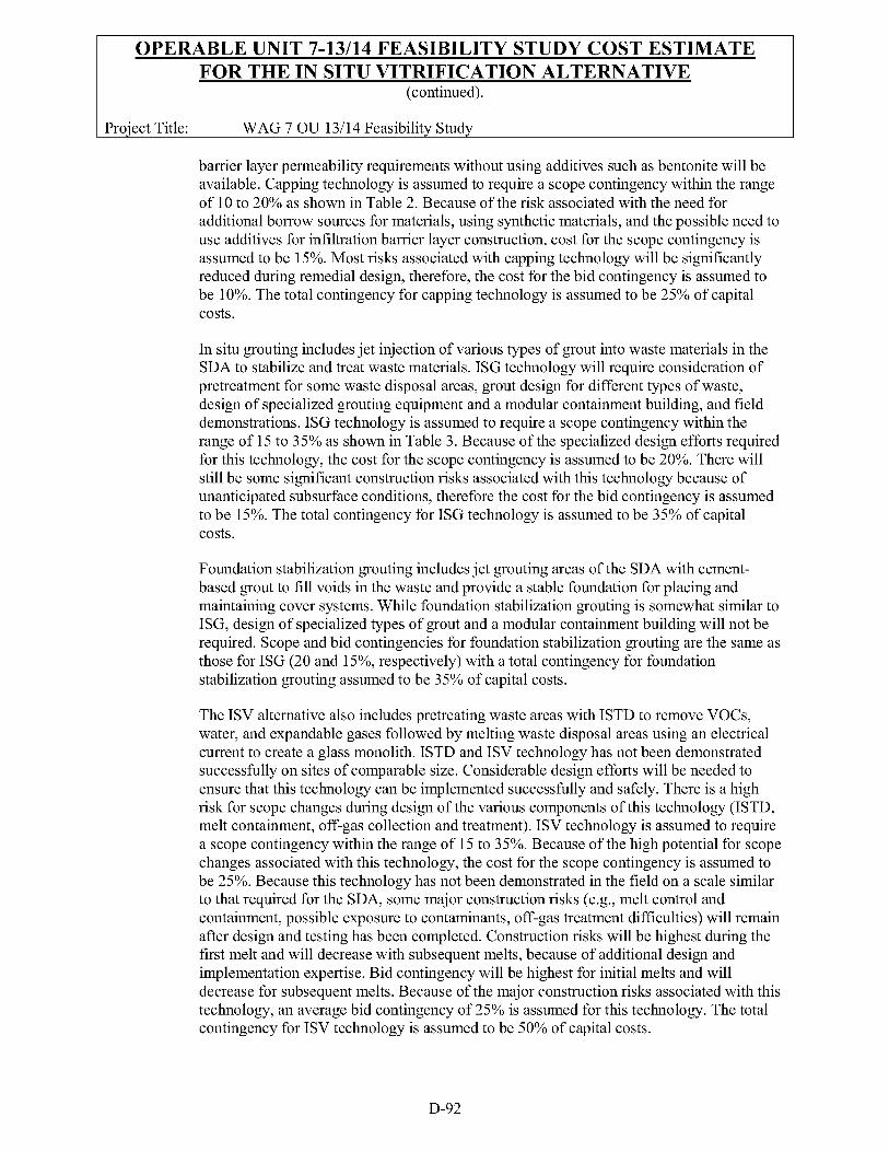
barrier layer permeability requirements without using additives such as bentonite will be available. Capping technology is assumed to require a scope contingency within the range of 10 to 20% as shown in Table 2. Because of the risk associated with the need for additional borrow sources for materials, using synthetic materials, and the possible need to use additives for infiltration barrier layer construction, cost for the scope contingency is assumed to be 15%. Most risks associated with capping technology will be significantly reduced during remedial design, therefore, the cost for the bid contingency is assumed to be 10%. The total contingency for capping technology is assumed to be 25% of capital costs.
In situ grouting includes jet injection of various types of grout into waste materials in the SDA to stabilize and treat waste materials. ISG technology will require consideration of pretreatment for some waste disposal areas, grout design for different types of waste, design of specialized grouting equipment and a modular containment building, and field demonstrations. ISG technology is assumed to require a scope contingency within the range of 15 to 35% as shown in Table 3 . Because of the specialized design efforts required for this technology, the cost for the scope contingency is assumed to be 20%. There will still be some significant construction risks associated with this technology because of unanticipated subsurface conditions, therefore the cost for the bid contingency is assumed to be 15%. The total contingency for ISG technology is assumed to be 35% of capital costs.
Foundation stabilization grouting includes jet grouting areas of the SDA with cement- based grout to fill voids in the waste and provide a stable foundation for placing and maintaining cover systems. While foundation stabilization grouting is somewhat similar to ISG, design of specialized types of grout and a modular containment building will not be required. Scope and bid contingencies for foundation stabilization grouting are the same as those for ISG (20 and 15%, respectively) with a total contingency for foundation stabilization grouting assumed to be 35% of capital costs.
The ISV alternative also includes pretreating waste areas with ISTD to remove VOCs, water, and expandable gases followed by melting waste disposal areas using an electrical current to create a glass monolith. ISTD and ISV technology has not been demonstrated successfully on sites of comparable size. Considerable design efforts will be needed to ensure that this technology can be implemented successfully and safely. There is a high risk for scope changes during design of the various components of this technology (ISTD, melt containment, off-gas collection and treatment). ISV technology is assumed to require a scope contingency within the range of 15 to 35%. Because of the high potential for scope changes associated with this technology, the cost for the scope contingency is assumed to be 25%. Because this technology has not been demonstrated in the field on a scale similar to that required for the SDA, some major construction risks (e.g., melt control and containment, possible exposure to contaminants, off-gas treatment difficulties) will remain after design and testing has been completed. Construction risks will be highest during the first melt and will decrease with subsequent melts, because of additional design and implementation expertise. Bid contingency will be highest for initial melts and will decrease for subsequent melts. Because of the major construction risks associated with this technology, an average bid contingency of 25% is assumed for this technology. The total contingency for ISV technology is assumed to be 50% of capital costs.
D-92
OPERABLE UNIT 7-13/14 FEASIBILITY STUDY COST ESTIMATE FOR THE IN SITU VITRIFICATION ALTERNATIVE
(continued).
Proiect Title: WAG 7 OU 13/14 Feasibilitv Studv
IV.
The scope and bid contingency percentages associated with this alternative are identified in Table 3. These percentages are applied to individual technologies in the cost estimate to establish a representative aggregate cost contingency.
Following the cost contingency guidance provided in Table 2 for each of the technologies, a representative contingency was selected within the range provided based on engineering judgment and the complexity, and size of the project, and inherent uncertainties related to the remedial technology. However, the guidance document does not address all of the remedial technologies identified in this alternative. Specifically, the foundation stabilization grouting, ISG, and ISTD and ISV technologies would be within a scope contingency range of 20 to 35% and are considered representative for this work and project scope.
SCHEDULE:
The following activities that comprise the RD/RA portion of the ISV alternative are provided. Table 4 shows the corresponding durations based on estimated crew productivity, regulatory reviews and approvals, and weather constraints inherent to the INEEL site.
V. PRESENT WORTH ANALYSIS:
Chapter 4 of the EPA Guidance provides guidance for present value analysis, The EPA Guidance states that the present value analysis of a remedial alternative involves four basic steps:
1. Define the period of analysis
2. Calculate the cash outflows (payments) for each year of the project
3. Select a discount rate to use in the present value calculation
4. Calculate the present value.
Periods of analysis for the ISV alternative include design and construction and O&M. The design and construction period for ISG, foundation stabilization grouting, and ISTD and ISV will occur over an estimated 4 years beginning shortly after issuance of a ROD for the site. Design, construction, and O&M costs for retrieving and restaging Pad A waste will be deferred until near the end of the project to reduce cost peaks and minimize the present value. The long-term monitoring will begin toward the end of the vegetation establishment period and will continue for 100 years.
Cash outflows for the ISV alternative will include payments for design and construction, periodic payments for major repairs, and annual O&M costs. EPA Guidance suggests that most capital costs should occur in the first year of remedial action when funds are committed for remedial action. While this suggestion might be a realistic assumption for short-duration remedial actions, it is not realistic for the ISV alternative because of the time required for design and construction. Cash outflows for the ISV alternative barrier would be paid on an annual basis as costs are incurred, beginning with the borrow source investigation, technology testing, and remedial design, and end with completion of the vegetation establishment period.
D-93
OPERABLE UNIT 7-13/14 FEASIBILITY STUDY COST ESTIMATE FOR THE IN SITU VITRIFICATION ALTERNATIVE
(continued).
Proiect Title: WAG 7 OU 13/14 Feasibilitv Studv
Annual capital cost payments vary with the level of activity, with relatively low annual payments during the borrow source investigation, technology testing, remedial design, readiness assessment, and vegetation establishment periods and relatively high annual payments during heavy construction periods (ISTD, ISV, grouting, and material excavation, processing, stockpiling, and placement). Periodic costs for major repairs would occur every 5 years concurrent with the 5-year reviews required by CERCLA. Periodic costs would begin 5 years after Phase 1 construction and continue through the O&M period. Annual O&M costs would begin the first year after completion of Phase 1 construction and continue for 100 years. In accordance with EPA Guidance requirements, 2002 constant dollars are used for all annual and periodic cash outflows.
The EPA Guidance requires using a real discount rate that approximates the marginal pretax rate of return on an average investment and has been adjusted to eliminate the effect of expected inflation. The real discount rate must be used with constant or real dollars that have not been adjusted for inflation. EPA Guidance recommends using a 7% real discount rate for present value analysis in most remedial action cost estimates. However, for federal facility sites being cleaned up using Superfund authority, EPA Guidance states that it is generally appropriate to apply real discount rates found in Appendix C of OMB Circular A-94. Suggested rates for federal facility sites are based on interest rates from Treasury notes and bonds and are appropriate because the federal government has a different cost of capital than the private sector. The most current version of Appendix C of OMB Circular A-94 (revised February 2002) proposes a real discount rate of 3.9% for programs with durations longer than 30 years. The 3.9% discount rate and constant dollars are used for the present value analysis of the ISV alternative. The present value of the ISV alternative is calculated using the equations provided in EPA Guidance.
VI. RISK AND UNCERTAINTY:
Further characterization and analysis of records are needed to better establish bounding conditions for safe and effective operations at individual melt settings. A preliminary review of the data shows a potential for excessive levels of combustible and alkaline materials, and perhaps inadequate soil at some melt settings. Spent fuel and sources with high ionizing radiation levels also may be encountered. A significant level of nonradioactive and radioactive treatability testing will be required in this alternative. This alternative will employ ISV and ISTD in unproven applications. Unique conditions for these technologies include high concentrations of potentially respirable plutonium powders in some waste containers, possible presence of spent fuel, high-gamma-energy sources, and gas cylinders. As previously discussed, a significant ISTD and ISV treatability test program has been assumed necessary to provide an adequate design and safety basis for implementing the alternative. Nevertheless, the total contingency for ISTD and ISV is assumed to be 50%.
Significant cost and schedule risks are associated with some of the materials proposed for additional soil coverage and the layers of the Modified RCRA Subtitle C cap. Increased haul distances also could increase by 50% the project schedule involving placing cover materials, depending on availability of additional trucks and the ability to manage them on the haul routes and on the site.
Processes and quantities for grouting activities have not been verified under actual site conditions. Because of the high level of uncertainty associated with grouting activities, the cost and schedule
D-94
OPERABLE UNIT 7-13/14 FEASIBILITY STUDY COST ESTIMATE FOR THE IN SITU VITRIFICATION ALTERNATIVE
(continued).
for these construction activities could increase by more than the 35% contingency applied to this technology.
VII. ESTIMATED MATERIAL VOLUME TABLES:
Tables 5 and 6 summarize the required materials for the Modified RCRA Subtitle C cover system and related design layers, thickness, and volume. Required materials for establishing and maintaining a minimum 10-ft soil cover during ISV, quantities of process materials consumed during ISTD and ISV, and quantities of treated secondary waste produced were defined earlier in the assumptions.
VIII. TABLES:
Table 1. Summary of remedial design costs as percentages of capital and operating costs.
Technology Percentage of Capital and Operating Costs Capping (Cover System) 6
In situ grouting 8
Foundation stabilization grouting 7
In situ vitrification 10
Table 2. Example feasibility study-level scope contingency percentages.
Remedial Technology Scope Contingency (%)
Soil excavation 15 -55
Synthetic cap 10 - 20
Clay cap 5 - 10
Surface grading and diking
Revegetation 5 - 10
5 - 10
D-95
OPERABLE UNIT 7-13/14 FEASIBILITY STUDY COST ESTIMATE FOR THE IN SITU VITRIFICATION ALTERNATIVE
(continued).
Proiect Title: WAG 7 OU 13/14 Feasibilitv Studv
Table 3. Summary of contingency costs as percentages of capital costs.
ISTD and ISV 25 25 50 ISTD = in situ thermal desorption ISV = in situ vitrification
Table 4. Remedial ActionRemedial Design testing, design, and construction.
Activity Description Estimated Duration
Waste records analysis 1.5 years
Site sampling and analysis
Borrow source investigation
Technology testing 5 years
Remedial design and procurement
Readiness assessment
Mobilization
2 years (overlaps records analysis by 1 year)
1 year (overlaps sampling and analysis by 1 year)
1.5 years (overlaps testing by 2 year)
1 year (no overlap with design)
0.5 year (no overlap with readiness assessment)
Pad A restaging
ISTD and ISV operations
2 years (overlap with ISTD and ISV operations)
15 years
Foundation and soil vault grouting
Grading fill and gravel placement
Asphalt, drainage, and filter layers
Placement of remaining layers
2 years (overlap with ISTD and ISV operations)
1 year (overlaps grouting by 1 year)
1 year (overlaps grading fill placement by 0.5 year)
1 year (overlaps clay, geomembrane, and filter by 0.5 year)
Venetation establishment 2 years (no overlap with placement of cap layers) ISTD = in situ thermal desorption ISV = in situ vitrification
D-96
OPERABLE UNIT 7-13/14 FEASIBILITY STUDY COST ESTIMATE FOR THE IN SITU VITRIFICATION ALTERNATIVE
(continued).
Proiect Title: WAG 7 OU 13/14 Feasibilitv Studv
Table 5. Distances and sources of borrow materials for the modified Resource Conservation and Recoverv Act Subtitle C cover svstem.
One-way Haul Material Issue Distance Source
Topsoil This material will consist of 1.5 mi This material is assumed to be organic silt loam and will be used to construct a topsoil layer to support vegetation on top of the cover system.
This material will be used to construct a number of the layers in the cover system including the general site grading fill, perimeter berm, and topsoil.
unprocessed organic silt loam derived from Spreading Area B.
Silt Loam 1.5 mi The majority of this material is expected to be unprocessed silt loam derived from Spreading Area B. Additional material is available from Ryegrass Flats (haul distance = 12 mi) and the WRRTF borrow area (haul distance = 34 mi). If permitted, some of this material could be excavated from Spreading Area B (haul distance = 1 mi).
Gravel
Sand
Riprap
This material will be used for the gravel gas collection, drainage, and coarse filter layers in the cover system. Sufficient quantities of good structural gravel and fines materials are available.
This material will be used for the fine filter layers in the cover system. No identified bank run borrow areas are available within the WEEL boundary.
Riprap will be used for erosion control. The majority of the mined riprap material at the WEEL has been used for other remedial actions.
Coarse Fractured Basalt
This material will be used for erosion control. The majority of the mined coarse fractured basalt material at the WEEL has been used for other remedial actions.
2.5 mi This material is assumed to be processed gravel derived from the Borax Gravel Pit.
45 mi This material is assumed to be processed sand derived from an off-Site borrow source.
5 mi This material is assumed to be processed material mined from a basalt outcropping identified 5 mi from the site, directly west of the RWMC and just outside the Big Lost River System.
This material is assumed to be processed material mined from a basalt outcropping identified 5 mi from the site, directly west of the RWMC and just outside the Big Lost River System.
5 mi
RWMC = Radioactive Waste Management Complex WRRTF = Water Reactor Research Test Facility
D-97
OPERABLE UNIT 7-13/14 FEASIBILITY STUDY COST ESTIMATE FOR THE IN SITU VITRIFICATION ALTERNATIVE
(continued).
Proiect Title: WAG 7 OU 13/14 Feasibilitv Studv
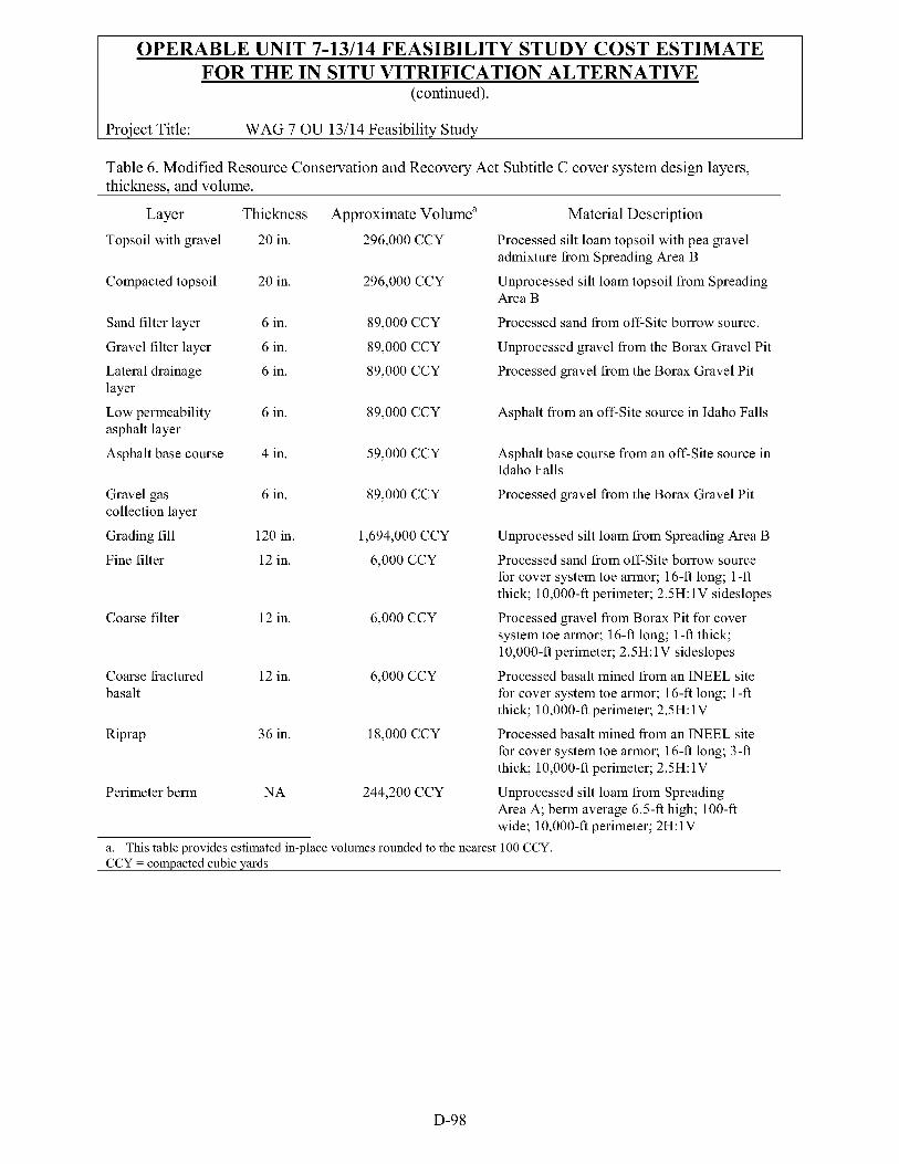
Table 6. Modified Resource Conservation and Recovery Act Subtitle C cover system design layers, thickness. and volume.
Layer Thickness Approximate Volumea Material Description
Topsoil with gravel 20 in. 296,000 CCY Processed silt loam topsoil with pea gravel admixture from Spreading Area B
Compacted topsoil
Sand filter layer
Gravel filter layer
Lateral drainage layer
Low permeability asphalt layer
Asphalt base course
Gravel gas collection layer
Grading fill
Fine filter
Coarse filter
Coarse fractured basalt
Riprap
20 in. 296,000 CCY Unprocessed silt loam topsoil from Spreading Area B
6 in. 89,000 CCY Processed sand from off-Site borrow source.
6 in.
6 in.
89,000 CCY
89,000 CCY
Unprocessed gravel from the Borax Gravel Pit
Processed gravel from the Borax Gravel Pit
6 in. 89,000 CCY Asphalt from an off-Site source in Idaho Falls
4 in. 59,000 CCY
89,000 CCY
Asphalt base course from an off-Site source in Idaho Falls
Processed gravel from the Borax Gravel Pit 6 in.
120 in. Unprocessed silt loam from Spreading Area B
12 in. 6,000 CCY Processed sand from off-Site borrow source for cover system toe armor; 16-ft long; 1 -ft thick; 10,000-ft perimeter; 2.5H: 1V sideslopes
Processed gravel from Borax Pit for cover system toe armor; 16-ft long; 1-ft thick; 10,000-ft perimeter; 2.5H: 1V sideslopes
Processed basalt mined from an WEEL site for cover system toe armor; 16-ft long; 1 -ft thick; 10,000-ft perimeter; 2.5H: 1V
Processed basalt mined from an WEEL site for cover system toe armor; 16-ft long; 3-ft thick; 10,000-ft perimeter; 2.5H: 1V
1,694,000 CCY
12 in. 6,000 CCY
12 in. 6,000 CCY
36 in. 18,000 CCY
Perimeter berm NA 244,200 CCY Unprocessed silt loam from Spreading Area A; berm average 6 . 5 4 high; 100-ft wide; 10,000-ft perimeter; 2H: 1V
a. This table provides estimated in-place volumes rounded to the nearest 100 CCY. CCY = compacted cubic yards
D-98
Y a a
. . _. ... ._ MATERIAU MATERIAU EQUIP EQUIP COST PE LABOR RATE TOTAL LABOR
UNIT UNIT LABORQTY LABORUNIT PER UNIT COST
Proiect Title:
.... . . _. ... .- EQUIP COST OTHER COST TOTAL COST
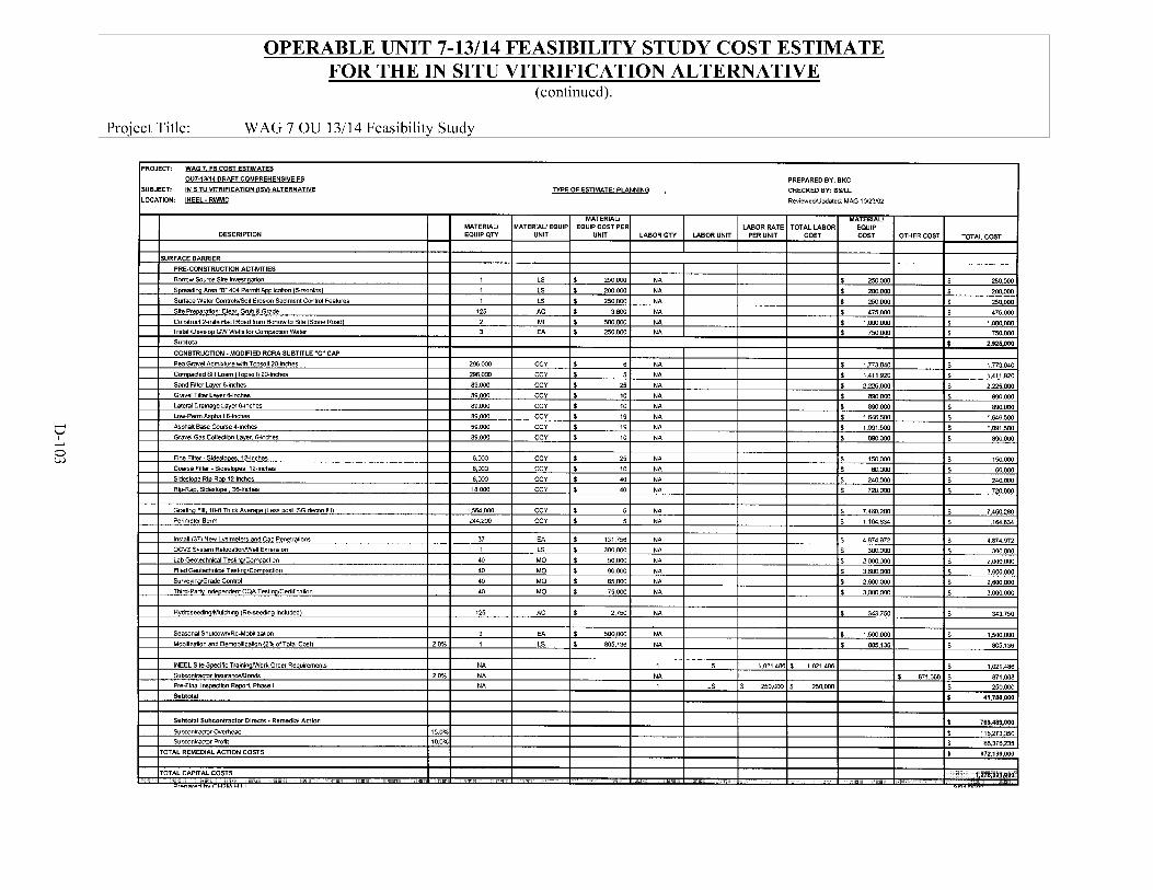
OPERABLE UNIT 7-13/14 FEASIBILITY STUDY COST ESTIMATE FOR THE IN SITU VITRIFICATION ALTERNATIVE
(continued).
WAG 7 OU 13/14 Feasibilitv Studv
PROJECT: WAG 7. FS COST ESTIMATES I OIJ7-1s114 DRAFT COMPREHENSIVE FS IN SITU VITRIFICATION llSW ALTERNATNE SUBJECT:
LOCATION: INEEL. RWMC
TYPE OF ESTIMATE PLANNING PREPARED B Y BKC CHECKED BY: BSlLL
RevlewedlUpdated MAG 10123102
Allocation br Other Dlreci Cos15 (ODCs) - 10% O f Total LabOr I I NA I I I I I
$ 4,265,120
$ 21,696,480
$ 3.480.820
$ 5.417.m
$ 3,634,460
$ 3,343,280 $ 1.817.230
$ 5,733.440
$ 1,806,420 $ 2,070,000
$ 5,119,51?
4.265.120
21.896.480
3.480.820
5,417,880
3.634.460
3.343.280 1.817.230
5,733,440
1,806,420 2.070.000
5.119.513
I I 1 I I I I I I I I I
I I I I t ITOTAL COST. FFPJCO Management and Oversight I I I I I I I I I I I s 5 ~ . 1 ~ , O w
Proiect Title:
ISTD Equipment Capital Costs
Electrical Power Supplylovehead Powerline ti-Frame
Elecblcal SubsManiTranrformers for Sile DiSblbubOn
OPERABLE UNIT 7-13/14 FEASIBILITY STUDY COST ESTIMATE FOR THE IN SITU VITRIFICATION ALTERNATIVE
(continued).
1 EA $ 5.256.620 NA $ 5,256,620 $ 5,256,520 3 MI $ 3 7 5 . m NA $ l . l W . W I 1.125.wO
2 EA $ 125.W NA $ 250.m $ 250.wO
WAG 7 OU 13/14 Feasibilitv Studv
ISV InslalladorWre ops ler l i rg (%of capital tosls)
ISTO Operatma1 Costs (per acre) 17 AC 153103 17 AC I 4,030,658 S 68.521.168 $ 2,602,751
Power COnsurnpliolllUtilihes NA NA 16 7.768.000
- s 14,192,528
$ 275,wO
s 33,188,350
$ 71,123,937
I 7 . 7 6 8 . m
1,508,437
1 , 6 5 0 . m
17.130.297
2.233.246
1,248,162
5.631.220
1,890,WO
7 . 2 W . W
1.95o.m
33.997.476
$ 174,166,200
$ 32.6W.oM)
Proiect Title:
DESCRIPTION
OPERABLE UNIT 7-13/14 FEASIBILITY STUDY COST ESTIMATE FOR THE IN SITU VITRIFICATION ALTERNATIVE
(continued).
......_..".I . .. . . -. ... .- MATERIAU MATERIW EQUIP EQUIP COST PER LABOR RATE TOTAL LABOR EQUIP EQUIP QTY UNIT UNIT LABOR QTV LABOR UNIT PER UNIT COST COST OTHER COST TOTAL COST
WAG 7 OU 13/14 Feasibilitv Studv
PROJECT: WAG 7. FS COST ESTIMATES I 007-13114 DRAFT COMPREHENSIVE FS IN SITU VITRIFICATION r1SW ALTERNATIVE SUBJECT:
LOCATION: INEEL. RWMC I TYPE OF ESTIMATE: PLANNING
PREPARED BY: BKC
CHECKED BY: ESlLL
Reviewedlllpdated MAG 1012U02
0 h,
OPERABLE UNIT 7-13/14 FEASIBILITY STUDY COST ESTIMATE FOR THE IN SITU VITRIFICATION ALTERNATIVE
(continued).
I Proiect Title: WAG 7 OU 13/14 Feasibilitv Studv
PROJECT: WAG 7. FS COST ESTIMATES
OUFiYi4 DRAFl COMPREHENSNE FS PREPARED 0Y: 0KC I SUIJECT: IN SITU VITRIFICATION WVl ALTERNATIVE
IL-10.: INEEL - m w c TYPE OF ESTIMATE PLANNING CHECKED 0Y: BSILL
ReviewediUpdated MAG ioiZ3mZ
MATERIAU MATERIAL1 MATERIAU MATERIAU EQUIP EQUIP COST PER LABORRATE TOTAL LABOR EQUIP
UNIT LABOR QTY LABOR UNIT PER UNIT COST COST OTHER COST TOTAL COST I I I
OPERABLE UNIT 7-13/14 FEASIBILITY STUDY COST ESTIMATE FOR THE IN SITU VITRIFICATION ALTERNATIVE
SUIJECT: IN SITU VlTRlFlCATlON IISWALTERNATIVE LOCATION INEEL-RWMC
TYPE OF ESTIMATE PLANNING , PREPARED B Y BKC CHECKED 0Y BSlLL RevieweWpdated MAG 10123102
OPERABLE UNIT 7-13/14 FEASIBILITY STUDY COST ESTIMATE FOR THE IN SITU VITRIFICATION ALTERNATIVE
(continued).
WAG 7 OU 13/14 Feasibilitv Studv
JPROJECT: WAG 7. FSCOST ESTIMATES I OU7.13114DRAFT COMPREHENSIVE FS
SUBJECT: IN SITU VITRIFICATION iisn ALTERNATNE
LOCATION INEEL - RWMC
TYPE OF ESTIMATE: PLANNING '
MATERIAU MATERIAL1 MATERIAU EQUIP EQUIP COST PEI
UNIT UNIT
1PDST.REMEDlAL ACTION OPERATIONS (100 M A R DURATION) I I I I I
INSTITUTIONAL CONTROLS FOR 100 YEARS
lmtall Permanent MaReWSuwey 12 EA $ 5 . m Replace Penmetw Seunty Fence lo .m LF S 20 Repair and Replace Perimetw Signs 1 LS s lo.m
I COVER MAINTENANCE I I I I Cover Maintenance Cost - 1W Year Duration Annua Cap Mantenam Costs I 100 I YR I t 75,WO
1 Inspection per Year m Early Fall for 5 yean Re-seed 10Acres EadYearfor5Years(50AcresTotal) 50 FC $ 15.000 1 In~pecbon Every 5th Year in Eady Fall Thereafter for 95 Years Re-seed 10 Acres Every 5 Years 19 E Y I $ 15.0W
NA
NA
I Air Mmltorlng (RadlologlcaUOrganis): I I I I I MonitOr 4 Exidbng CAM5 1W I E W I $ I ,m I Replacement ParWEqupment Core (Assume iO%af Total CostF) I I 1 I LS I $ 33,530
Subtotal Sumillance and MonIIorIng (Sampling B Monitoring Activities1
WAG 1 MANAGEMENT
WAG 7 Management (@ 5% Of other post-PA opera110ns costs1 5% I Annual Data Summary Report (100 reports @ 2W hwreport) 1 1 I I I WAGWide UA 5 Year Reviews for 1W Years (20 5-year rew-~ @ BM) hrslrenw) I I
ITOTAL COST. Posl.Remcd a1 Actlon Operallonr (100 Year Dural on) I I I I I
Prepared byCHZM HILL
PREPARED BY: BKC CHECKED BY: BSlLL
RevienedlUpdated MAG 1OQ3102
MATERIAU LABOR RATE TOTAL LABOR EQUIP
LABORQTY LABORUNIT PERUNIT COST COST OTHER COST TOTAL COST I I I I I I I I I I I I
I I I I I I I NA $ 60.W s 6o.W 0
NA I 2w.m $ 2 W . W 0 NA $ 10,m f 1 O . W O
s 270.WO.O
NA $ 7 5 0 0 , m t 7.5W.W S 7,540.000.0D
8 950,936 E V I I 1 1 . m $ 88.m $ 8.W $ 854,936 $
6 713.202 E V I I 1l.m $ 66.W $ 6.m $ 641,ZOZ $
5.646.183 E W t 5.5W $ 522.500 $ 47.500 $ 5,076,183 $ 95
NA $ 731,032 $ 731.032
3121R002
Attachment D -5
Operable Unit 7-13/14 Feasibility Study Cost Estimate for Retrieval, Treatment, and Disposal Alternative
The information in this cost estimate summary table is based on the best available information regarding the anticipated scope of the remedial alternative. Changes in the cost estimate are likely to occur as a result of new information and data collected during the engineering design, safety reviews, and remedial alternative. Major changes may be documented in the form of a memorandum in the administrative record$le, an explanation of signijicant differences, or a ROD amendment. This is an order-of- magnitude engineering cost estimate that is expected to be within -30 to +50percent of the actual project cost.
D-105
D-106
OPERABLE UNIT 7-13/14 FEASIBILITY STUDY COST ESTIMATE FOR THE RETRIEVAL, TREATMENT, AND DISPOSAL ALTERNATIVE
Project Title: Estimator Brian K. Corb Date: December 2002 Estimate Type: Planning Reviewed/Appr: Lee Lindig/Bruce L. Stevens
WAG 7 OU 13/14 Feasibility Study
I. SCOPE OF WORK:
A. Remedial Design and Remedial Action
The RTD alternative involves the retrieval, ex situ treatment, and disposal of the onsite buried waste within the SDA. The scope of this alternative is similar to the in situ treatment alternatives, primarily encompassing burial sites containing the TRU waste from the RFP and MLLW (Pits 1 through 6 and 9 through 12, Trenches 1 through 10, and Pad A). Area and volume data for the TRU pits, trenches, and Pad A are provided in Table 1. The premise of this alternative is that TRU waste and soil retrieved would be characterized, treated as required to meet waste acceptance criteria (WAC), packaged, and transported to the WIPP for disposal. All other retrieved materials, including LLW and MLLW would be treated onsite to meet regulatory and risk-based requirements and placed in an onsite engineered disposal facility. The excavated pits and trenches would be backfilled as the retrieval action proceeds and systematically capped with a low-permeability modified RCRA Subtitle C cover. The onsite engineered disposal facility would be capped with an ICDF type cover that would be incorporated into the final Subtitle C cover over the entire SDA. Ancillary facilities and programs then would be established to maintain the covers and provide for the long-term monitoring.
As part of the RTD alternative, as with the ISG and ISV alternatives, the SVRs will be grouted in place before final capping. Additionally, remaining LLW trenches where activation and fission products (and other groundwater COCs) have been disposed of will be grouted to immobilize contamination before the cap is placed. The remaining pit and trench areas in the SDA (Trenches 12 through 58) will be foundation grouted to provide additional stability and prevent subsidence for the final cap.
The retrieval, treatment, and disposal of waste involve a relatively complex process. After the major paperwork portion of the alternative is complete (ROD, design and safety analyses, and procurement), the retrieval action will start, which includes the following main steps: site-preparation, in situ VOC extraction using ISTD, predesign characterization for soil stability and other design characteristics, constructing support buildings, removing clean overburden, constructing primary and secondary containment, establishing contamination controls and curtains, retrieving waste, segregating TRU and non-TRU waste and soil, treatment, characterization to meet waste acceptance criteria for disposal site, repacking material for disposal, transporting material to disposal site, constructing the onsite disposal facility, grouting SVRs and remaining LLW trenches containing groundwater COCs, constructing caps over SDA and onsite engineered disposal facility, installing controls, implementing institutional controls, groundwater monitoring, and cap maintenance.
D-107
OPERABLE UNIT 7-13/14 FEASIBILITY STUDY COST ESTIMATE FOR THE RETRIEVAL, TREATMENT, AND DISPOSAL ALTERNATIVE
(continued).
Proiect Title: WAG 7 OU 13/14 Feasibilitv Studv
B. Long-Term Monitoring and Maintenance
After the Remedial Action has been completed, long-term monitoring and maintenance will continue for 100 years, with CERCLA reviews conducted every 5 years. Long-term environmental monitoring will be conducted for groundwater, vadose zone water, surface water, and air. In addition, the cover system itself will be monitored annually during the first 5 years following completion of construction (beginning after the vegetation establishment period). With stabilized waste remaining onsite, a long-term groundwater- monitoring program would be required to verify the protectiveness of the remedial action. The evaluation assumes that this program would include several perimeter wells, which would be monitored on a quarterly basis for the first two years following completion of the remedial action. For the next 3 years, the wells would be monitored on a semiannual basis. Following completion of the 5-year review, the program presumably could be reduced to annual monitoring. After the completion of annual monitoring, the monitoring frequency will be reduced to every 5 years concurrent with the 5-year reviews required under CERCLA. The cover system will be monitored for vegetation density, erosion damage, and differential settlement. Areas of erosion damage will be repaired with additional topsoil and earth fill, and reseeded. Areas without established vegetation will be reseeded.
11. BASIS OF ESTIMATE:
The basis of the estimate was developed from the following sources to provide a defensible and comparative cost of the remedial alternatives. The applicable sources available for the ISG alternative include:
A. EPA 540-R-00-002, “A Guide to Developing and Documenting Cost Estimates During Feasibility Study,” July 2000
B. INEEL, “Cost Estimating Guide,” DOE/ID-10473 September 2000
C. “Environmental Assessment and Plan for New SilKlay Source Development and Use at the Idaho National Engineering and Environmental Laboratory,” DOE/EA-1083, May 1997
D. Caterpillar Equipment Performance Handbook, 3 1 st Edition
E. The INEEL Site Stabilization Agreement, Union Labor Agreement
F. Facilities Unit Costs-Military Construction, PAX Newsletter No. 3.2.2-1 0, March 2000
G. ICDF Construction Cost Estimate, Cap Construction Cost (CH2MHILL, December 2000)
H. Subject Matter Expert, R. Smith, WIPP Transportation Manager
I. Subject Matter Expert, J. Bradford, RFETS, Waste Management Department
J. Subject Matter Experts-M. Jackson, BBWI, and T. Borschel, BBWI, “Availability of Borrow Source Material at the INEEL”
D-108
OPERABLE UNIT 7-13/14 FEASIBILITY STUDY COST ESTIMATE FOR THE RETRIEVAL, TREATMENT, AND DISPOSAL ALTERNATIVE
(continued).
Proiect Title: WAG 7 OU 13/14 Feasibilitv Studv
K. Pit 9, RWMC, Cost Estimate (Building Data)
L. 710 Building Demonstration Project
M. BBWI INEEL Site Craft and Professional Services Labor Rates, February 2002
N. Advanced Mixed Waste Treatment Project (AMWTP) Construction and Operational Cost Estimate.
0. OMB, 2002, “Guidelines and Discount Rates for Benefit-Cost Analysis of Federal Programs,” Appendix C, “Discount Rates for Cost-Effectiveness, Lease Purchase, and Related Analyses,” OMB Circular A-94, February 2002.
P. R. S. Means, 2002, Heavy Construction and Industrial Building Unit Costs Data 16” edition, Kingston, Massachusetts.
Q. INEEL Analytical Laboratory Unit Cost
R. Win Porter, Waste Policy Center conversation with Kira Sykes, CH2MHILL regarding the “Top-To-Bottom Review of the Carlsbad Field Office”. Dr. Ines Triay, Carlsbad Field Office, August 29,2001
S. DOE-ID, 2001, “Architectural Engineering Standards,” Rev. 28, U.S. Department of Energy Idaho Operations Office, Idaho Falls, Idaho
T. DOE-STD-1020-96, “Natural Phenomena Hazards Design and Evaluation Criteria for Department of Energy Facilities,” U.S. Department of Energy, January 1996.
U. DOE 0 420.1, “Facility Safety,” U.S. Department of Energy, November 22,2000
V. Loomis, G. G., A. P. Zdinak, and C. W. Bishop, 1997, Innovative Subsurface Stabilization Project - Final Report, Rev. 1. INEL-96/0439, Idaho National Engineering Laboratory, Idaho Falls, Idaho
W. Armstrong 2002, Draft Operable Unit 7-13/14 Evaluation ofIn Situ Grouting, Idaho National Engineering Laboratory, Idaho Office Operations, Idaho Falls, Idaho.
111. ASSUMPTIONS:
The primary work associated with the RTD alternative involves the retrieval, ex situ treatment, and disposal of onsite buried waste in the SDA. Additionally, grouting, capping, and monitoring are main components of this alternative. The following section includes the primary assumptions that identify and quantify technical and cost parameters to provide a basis for the cost estimate and bound the information based on available data.
A. Management and Oversight
D-109
OPERABLE UNIT 7-13/14 FEASIBILITY STUDY COST ESTIMATE FOR THE RETRIEVAL, TREATMENT, AND DISPOSAL ALTERNATIVE
(continued).
Proiect Title: WAG 7 OU 13/14 Feasibilitv Studv
A. 1 Project Management for the BBWI oversight of this alternative has been estimated based on an average classification of job categories using the BBWI rates. The numbers of FTE are based on 2,000 MH per person per year.
A.2 The RD/RA schedule assumes that the budgetary funding will not be constrained.
A.3 The RD/RA schedule assumes no unexpected delays will result from changes to the USQ/SAR process.
A.4 The estimate assumes that the INEEL site resources (i.e., CFA, medical facilities, geotechnical laboratory, fire department, security, utilities at the SDA) will be available during the project.
B. Design and Preconstruction
B. 1 The design will be developed in several initial phases to support early activities necessary for the remedial action-in situ VOC extraction and predesign characterization. These activities, once planned and designed, will be conducted in the field during the remedial design phase and in parallel with the remedial design and safety analysis documentation preparation.
B.2 Preconstruction activities-Borrow source investigations, cultural resource clearance, developing an onsite source of basalt rock, field-scale testing of jet grouting into waste, testing grout formulation, final design, readiness assessment completion, and mobilization.
B.3 For grouting, design activities will include integrating the drill mast and hydraulic head of the grouting equipment onto a mobile gantry crane and designing and specifying lights, camera systems, and radiation monitors. Grout formulations will be tested with surrogate and actual waste on bench scale to optimize formulations.
C. Capital Costs, Unit Rates, and other Pricing Assumptions
C. 1 The unit prices have been developed from a crew build-up to process, load, haul, place, and compact. The volume of material represented in the cost tables identifies CCY. The appropriate factors convert the estimated unit material weights (bank, loose, and fill) and are factored into the equipment productivity.
c.2 Crew labor rates were developed based on hourly rates stipulated in the INEEL Site Stabilization Agreement. Labor and equipment spreads were developed based on the assumed achievable daily productivity to support the project schedule. Other factors that influenced the selection of labor and equipment quantities include safety, level of PPE of the work to be performed, haul routes, and availability of resources on the INEEL. Each daily crew cost also includes field oversight personnel such as the HSO, superintendents, foremen, CIHs, maintenance personnel, and allocation of supplies (e.g., fuel, oil, grease, and spare parts).
D-110
OPERABLE UNIT 7-13/14 FEASIBILITY STUDY COST ESTIMATE FOR THE RETRIEVAL, TREATMENT, AND DISPOSAL ALTERNATIVE
(continued).
Proiect Title: WAG 7 OU 13/14 Feasibilitv Studv
C.3 Primarily all capital equipment and pricing were selected from commercially available sources or similar projects allowing a scale factor to be applied to yield an estimated cost of the conceptual equipment and operational requirements. Equipment installation cost is considered to be a significant variable in estimating individual components of a given system. For the basis of cost, the installation cost of the capital equipment was based on a percentage of the capital costs ranging from 1 10 to 160% of the estimated capital expenditure based on the unknowns and level-o f-complexity.
C.4 Subcontractors bond and insurance rate of 2% of the total subcontractor dollars includes overhead and profit based on each alternative.
C.5 The estimate includes an allocation for the INEEL specific work order PRD requirements and safety meetings. Because this estimate includes primarily unit prices, the labor cost is estimated to be 40% of the unit prices and, based on historical data, INEEL-specific process cost is approximately 6% of the total labor dollars.
D. Site Preparation and Support Activities and Facilities
The following assumptions have been made:
D. 1
D.2
D.3
D.4
D.5
D.6
D.7
D.8
The Treatment Facility, Lag Storage, and the TRUPACT loading Facility likely will be constructed at a centralized location adjacent to the SDA.
The allowable soil-bearing capacity for the planned facilities will not impact the costs.
The existing utilities at or adjacent to the SDA are sufficient to support the planned facilities.
The estimate includes cost to construct local off-road haul routes for delivery of soil material for the cap construction. Costs for road maintenance on the INEEL and off-Site costs associated with the transporting the containerized waste to WIPP are not included in the estimate.
A grout batch plant will be set up near the SDA sized to produce a maximum of 500 yd3 of grout per day.
Materials to formulate the grout will be shipped in from vendors by rail car. Access and transfer roads will be constructed to deliver the materials to the site.
Administrative and equipment buildings or trailers will be installed in the SDA to support operational controls, radiation controls, and personnel facilities.
In situ thermal desorption will be applied to areas of the SDA to pretreat waste with high concentrations of oils. These areas likely will comprise less than 1 acre of the SDA.
D-111
OPERABLE UNIT 7-13/14 FEASIBILITY STUDY COST ESTIMATE FOR THE RETRIEVAL, TREATMENT, AND DISPOSAL ALTERNATIVE
(continued).
Proiect Title: WAG 7 OU 13/14 Feasibilitv Studv
D.9 As described in the PERA, it is believed that for health and safety, as well as waste handling, it is advantageous to remove the VOCs before excavation. Approximately 1,000 tons of C C 4 are known to have been disposed of within the SDA. The necessary VOC treatment would be accomplished through characterization and in situ VOC extraction using ISTD and off-gas collection. Early design efforts would be focused on preparing the necessary design documentation to perform the VOC extraction.
D. 10 For the PERA estimate, it is assumed that in situ VOC extraction would require approximately two years for installation and operation to remove the mass of VOCs. This duration has been established to allow both the VOC extraction and predesign characterization to occur during the remedial design phase.
D. 1 1 Predesign characterization will be conducted early in the remedial design phase to provide necessary data to complete the design. Soil stability and other physical design characteristics will be determined in this phase. Probing may be used to determine the thickness of clean overburden and general chemical and radiological concentrations to decide the amount of soil that may be used as clean backfill. Early design efforts would be focused on preparing the necessary design documentation to perform the characterization.
D. 12 For the PERA estimate, it is assumed that the predesign characterization will require two years to acquire all the data necessary to support the design. For cost purposes, it is assumed that noninvasive probing and geoprobe equipment will be used.
E. Health and Safety
E. 1 Presumably, all excavation work will be performed in Level B PPE. Productivities and crew labor have been adjusted to be representative of the expected level of effort. It is assumed that after the earthen fill is placed over the SDA, all earthmoving operations for the cover system can be performed in Level D.
F. Constructing Supporting Structures and Facilities
F.l General Requirements-All buildings will be designed and constructed to the IBC. Frost depth for building foundations is 5 ft (DOE-ID 2001). The ground snow load of at least 35 lb/ft2 shall be used in ASCE calculations and a minimum roof snow load of 30 lb/ft2 shall be used for all buildings (DOE-ID 2001). Retrieval buildings and other structures shall not be designed for tornado loads (DOE-ID 2001). All structures shall be designed for PC 2 standards for wind, seismic, and flood design requirements. The PC 2 seismic return period is 1,000 years (STD-1020). The fastest wind speed for INEEL structures is 70 mph, and the 3-second gust wind speed is 90 mph (DOE-ID 2001). The design mean hazard annual probability for floods is 5E-04, or a 2,000-year return period (STD-1020). Fire protection systems shall meet or exceed the minimum requirements established by the NFPA and DOE 0 420.1. Heating, lighting, and ventilation systems are required for all supporting structures, as human occupancy will occur in each of the buildings.
D-112
OPERABLE UNIT 7-13/14 FEASIBILITY STUDY COST ESTIMATE FOR THE RETRIEVAL, TREATMENT, AND DISPOSAL ALTERNATIVE
(continued).
Proiect Title: WAG 7 OU 13/14 Feasibilitv Studv
G.
H.
On-Site Engineered Landfill
G. 1 The onsite engineered landfill is assumed to be similar to the design for the ICDF, and the landfill necessary for the RTD alternative will require two waste cells, one of which would be constructed before the retrieving any waste. The second cell is assumed to be located in an area that previously had waste disposal, and will be constructed following retrieving waste from that area. Both cells are to be constructed within the SDA. The necessary total capacity of the landfill is 250,000 yd3, which would accommodate all MLLW and LLW and include volume increase to account for waste treatment and cover soil.
G.2 Construction of the disposal facility would require excavating the landfill cells, installing lining and leachate collection systems, and constructing leachate transmission, storage, and treatment systems. Table 2 provides the components and quantities assumed necessary for the bottom lining system, and for the side slope lining system.
G.3 Borrow sources for materials would be Spreading Areas B for the silt loam, which would require using a bentonite additive. Drainage gravel and the gravel operations layer will consist of processed gravel from the Borax Gravel Pit. Twenty 20-yd3 trucks will be used to haul material; each truck will deliver 10 loads per day to the site.
G.4 The leachate collection, transmission, treatment, and disposal system will consist of perforated collection piping on the bottom of the landfill, a leachate collection sump and evaporation pond outside of the landfill, and transmission piping to the sump and pond. An estimated 1,200 ft of perforated 12-in. pipe and 500 ft of nonperforated 12-in. pipe are assumed for the disposal facility. The leachate collection sump would have a pumping system to transfer leachate to the evaporation ponds.
G.5 For this PERA, it is assumed that two ponds would be constructed with approximate surface dimensions of 200 x 350 ft, and average depths of 8 ft each. Table 3 provides the components and quantities for the evaporation pond liner systems. Borrow sources for the evaporation pond liner systems would be the same as described for the landfill.
Buildings and Structures
H. 1 Administrative Buildings
Administrative building(s) are to be constructed for the RTD alternative. Existing administrative buildings at the RWMC will not be used because of their distance from the SDA, and the extended duration of the alternative. The administrative building(s) would be approximately 10,000 ft2 to provide office space, meeting rooms, shift worker lockers with change rooms and showers, radiological control offices, and lunchroom space. With the large number of personnel, this size administrative building(s) is believed necessary. Project management, engineering,
D-113
OPERABLE UNIT 7-13/14 FEASIBILITY STUDY COST ESTIMATE FOR THE RETRIEVAL, TREATMENT, AND DISPOSAL ALTERNATIVE
(continued).
Proiect Title: WAG 7 OU 13/14 Feasibilitv Studv
H.2
H.3
H.4
project controls, and other management/administrative personnel would be located in the administrative buildings. It is assumed that these personnel would not require significant medical monitoring.
Equipment Maintenance and Storage Area
The equipment maintenance and storage area is necessary for the RTD alternative. This building or buildings would be approximately 10,000 ft2 and would house equipment such as fire trucks, forklifts, trucks, spare waste bins, PPE, and other equipment and supplies that will be used during the course of the remedial action. This building would have separate space for performing maintenance on the various pieces of equipment used by the RTD alternative, including, but not limited to, treatment facility equipment, retrieval facility equipment, and excavation. Based on the substantial amount of equipment, materials, and supplies required for this alternative, this size maintenance and storage area is necessary. Because equipment would be decontaminated before entry in this building, it is assumed that personnel would not require significant medical monitoring.
Decontamination Area
A building will be provided where equipment can be decontaminated. Because of the large equipment that would be used by the RTD alternative, several large decontamination areas would be necessary. For the this PERA, it is assumed that the decontamination building would be 5,000 ft2 and that two large equipment doors would allow movement of heavy equipment into the building. Only standard decontamination equipment is needed. Personnel that work in the decontamination building would be included in the medical monitoring program, specifically for radionuclides.
Lag Storage Building
The lag storage building will be constructed to initially separate and store TRU and non-TRU waste before transfer to the treatment facility. Nondestructive assay (NDA) of the waste bins will be used to separate the TRU and non-TRU waste.
The lag storage facility should be sized with sufficient storage area to accommodate 16 weeks worth of retrieval (1 6 weeks x 4 daydweek x 100 yd3/day = 6,400 yd3) in storage. Therefore, the lag storage facility, based on assumed waste packing fractions and waste bin sizes, is 70,000-ft2. Optimally, the lag storage facility would be kept half full to ensure adequate volume for treatment should the retrieval operation be stopped, and sufficient storage space is available for retrieval waste should the treatment operation be stopped. The square footage allows for the equipment and shielding between the NDA equipment and the waste storage area, and allows for efficient movement of waste bins through the storage facility.
The lag storage facility will have a reinforced-concrete floor capable of withstanding loads of 2,000 lb/ft2. Waste will be moved within the lag storage facility using forklifts; therefore, no overhead crane is necessary. It is assumed that
D-114
OPERABLE UNIT 7-13/14 FEASIBILITY STUDY COST ESTIMATE FOR THE RETRIEVAL, TREATMENT, AND DISPOSAL ALTERNATIVE
(continued).
Proiect Title: WAG 7 OU 13/14 Feasibilitv Studv
ceiling heights of 15 ft would be adequate. Two large doors would allow entry and exit.
H.5 Treatment Facility
It is assumed that the existing AMWTP is representative of requirements for the TRU and non-TRU treatment facility with the addition of the steam-reforming component of the LLW treatment train. The construction and operational costs have been scaled based on the expected waste material feed rates.
The treatment facility will be separated into separate TRU and non-TRU processing areas. Based on expected waste volume and mass in comparison to those that will be processed by the AMWTP, it is estimated that the treatment facility required for the RTD alternative will be 130,000 ft2, and two stories approximately 44 ft high. Table 4 lists the treatment equipment components and feed rates needed.
The off-gas system listed in Table 4 consists of the following components: quencher, venturi scrubber, packed bed scrubber, demister, reheater, catalytic oxidation, parallel HEPA filters, carbon filters, and parallel off-gas fans. The off- gas would then exit the stack of the treatment facility. The secondary liquid waste system listed in Table 4 is an evaporator that would evaporate the scrubber solution into a brine. The brine would require disposal.
The treatment facility would be designed and constructed as a Category 2 Nuclear facility and include negative pressure process areas, airlocks, multiple contamination control zones, cascading ventilation systems, multiple HEPA filtration on building and process exhaust streams, and continuous monitoring of emissions.
In addition to the treatment facility components, waste opening and sorting will be conducted remotely by facility operators. Gloveboxes, large and small manipulators, and sizing equipment will be necessary to handle the waste as part of the process. Personnel entry would be possible using Level A PPE but would not be part of routine operations.
Safety issues in the processing facility include: preventing and suppressing fire, preventing and mitigating explosion hazards, contamination controlling, radiation shielding, and normal industrial hazards. The facility would be designed and constructed to mitigate these hazards. Criticality control is not anticipated to be a concern in this facility (though it would be monitored) but would be investigated further in the design phase.
The cost estimate includes allowances for operational start up and testing for regulatory approval and provides a cost allowance to decommission the facility after use.
D-115
OPERABLE UNIT 7-13/14 FEASIBILITY STUDY COST ESTIMATE FOR THE RETRIEVAL, TREATMENT, AND DISPOSAL ALTERNATIVE
(continued).
Proiect Title: WAG 7 OU 13/14 Feasibilitv Studv
I.
J.
H.6 WIPP Transportation Storage
A secondary storage building must be constructed for the RTD alternative to provide storage space for waste shipments before transport to WIPP. Each drum of waste requires a 225-day wait following final packaging before it can be certified for transport to WIPP. Based on the expected TRU production rate, the WIPP Transportation Storage facility requires approximately 75,000 ft2 and waste drums will be stacked three high. Waste stacking shelves are included in the cost estimate. This storage building is equipped with two large doors to allow for easy waste entry and exit.
The cost estimate includes capital cost to construct a TRUPACT loading facility and the necessary crew labor cost to load and assemble waste containers for transport to WIPP.
Retrieval, Ex Situ Treatment, and Disposal Assumptions
I. 1 Overburden Soil Removal
Clean overburden, assumed to be the top 5 ft over all the TRU pits, trenches, and Pad A, would be removed. Table 1 lists the total volume of clean overburden as 113,000 m’. The retrieval schedule indicates that the clean overburden would be removed in approximately 1 year. The overburden would be stockpiled, further characterized, and later used as backfill. No containment would be required for removal of this soil, as it is assumed clean. The stockpile location could be located outside the area of contamination if necessary. Stockpile management would occur during the entire RTD alternative duration, and would include run-on and run-off control, and wind control.
Construction of Primary and Secondary Containment Structures
J. 1 The same general criteria for constructing the support facilities apply to the constructing of the primary and secondary containment structure. All buildings will be designed and constructed in accordance with the IBC. Frost depth for building foundations is 5 ft (DOE-ID 2001). The ground snow load of at least 35 lb/ft2 shall be used in ASCE 7 calculations and a minimum roof snow load of 30 lb/ft2 shall be used for all buildings (DOE-ID 2001). Retrieval buildings and other structures shall not be designed for tornado loads (DOE-ID 2001). All structures shall be designed for PC 2 standards for wind, seismic, and flood design requirements. The PC 2 seismic return period is 1,000 years (STD-1020). The fastest wind speed for INEEL structures is 70 mph, and the 3-second gust wind speed is 90 mph (DOE-ID 2001). The design mean hazard annual probability for floods is 5E-04, or a 2,000-year return period (STD-1020). Fire protection systems shall meet or exceed the minimum requirements established by the NFPA and DOE 0 420.1.
5.2 The primary and secondary containment structure is a double-walled structure that would be erected over a pit or trench area. Pits that have an extremely wide span,
D-116
OPERABLE UNIT 7-13/14 FEASIBILITY STUDY COST ESTIMATE FOR THE RETRIEVAL, TREATMENT, AND DISPOSAL ALTERNATIVE
(continued).
Proiect Title: WAG 7 OU 13/14 Feasibilitv Studv
such as Pit 5 , would require using H-piles to construct a wall down the center of the pit on one side of the structure. The H-piles would be driven into the bedrock. The primary and secondary containment structure will be constructed to Nuclear Facility Category 2 standards.
5.3 The primary and secondary containment structure would be equipped with radiation alarm systems such as constant air monitors that would alarm when airborne contamination reached unacceptable levels. Criticality alarms would be installed in the primary containment structure. These alarm systems would require periodic testing and calibration.
5.4 The following is a listing of the number, size, and encompassed waste areas for each primary and secondary containment structure:
J.4.a Building 1 (Trenches 1, 5 , 7, and 9): 1,180 x 176 ft
J.4.b Building 2 (Pits 1 and 2, divided down the middle, part 1): 115 x 950 ft
J.4.c Building 3 (Pits 1 and 2, divided down the middle, part 2): 115 x 950 ft
J.4.d Building 4 (Trenches 3,4, 6, and 10): 1,140 x 140 ft
J.4.e Building 5 (Trench 2): 1,140 x 90 ft
J.4.f Building 6 (Pits 4 and 6): 1,430 x 140 ft
J.4.g Building 7 (Pits 10 and 11): 1,410 x 140 ft
J.4.h Building 8 (Pit 12): 115 x 300 ft
J.4.i Building 9 (Pit 3): 140 x 500 ft
J.4.j Building 10 (Pad A): 230 x 410 ft
J.4.k Building 11 (Pit 5 , divided down the middle, part 1): 180 x 430 ft
5.4.1 Building 12 (Pit 5 , divided down the middle, part 2): 205 x 340 ft
J.4.m Building 14 (Pit 9): 140 x 390 ft.
J.5 It is assumed that as the remedial action is completed in a phased manner the containment buildings will be dismantled and collapsed into the excavated trenches and backfilled. A cost allowance of 25% of the capital expenditures of the building costs is assumed to be representative of the estimated level of effort to dispose of buildings and equipment.
D-117
OPERABLE UNIT 7-13/14 FEASIBILITY STUDY COST ESTIMATE FOR THE RETRIEVAL, TREATMENT, AND DISPOSAL ALTERNATIVE
(continued).
Proiect Title: WAG 7 OU 13/14 Feasibilitv Studv
K. Contamination Control at the Digface
K. 1
K. 2
K. 3
K. 4
K. 5
K. 6
K. 7
K. 8
Contamination control at the digface would consist of a series of moveable flame- retardant plastic and metals curtains similar to those used in the INEEL TSA to protect against leaking boxes. The curtains would be hung from a gantry crane from the ceiling of the primary and secondary containment structure. The gantry crane would also apply water, foams, and foggers to keep dust and contamination at a minimum within the retrieval operation. The crane would provide support for lifters, detectors, metal curtains, and other equipment.
The curtain system would incorporate a ventilation system and is assumed to provide adequate contamination control to allow the work to proceed. Negative pressure would be applied to the digface at all times and directed to HEPA filters to control contamination and keep it from entering the secondary containment structure.
The air exhausted from the retrieval zone would be fully saturated with water vapor because mist will be applied to control airborne contamination. Some water vapor would condense in the ductwork leading to the air treatment system. This condensate would be recycled through the retrieval-face misting system, as would other condensates. The air treatment system consists of chillers, demisters, heaters, and banks of HEPA filters in two parallel systems to provide redundancy if one system failed. The chillers would cool the air, which would decrease the dew point and cause mists to form. The air would then pass through a demister, which would remove moisture from the air. The air would then pass through heating elements to raise the temperature to about 10°C above dew point. The air would then pass through the HEPA filters.
Water will be used to control dust within the containment structure, however, this may have an impact on moderator control with respect to criticality. Another substance may be required and is not included in this cost estimate.
The cost estimate includes stand-by excavation and sizing equipment that can be rotated out for maintenance and equipment difficulties to minimize productivity loss.
The curtains also would be equipped with an air lock system to move drums and waste out of containment. The design of the air lock systems would be similar to those used in nuclear facilities.
Dust suppression would be accomplished by keeping the soil relatively moist and operating the retrieval equipment carefully to minimize waste disturbance. Aerosol foggers, sprays, and foams would be available in case additional contamination control is needed during excavation.
The moveable metal curtains hung from the gantry crane would move with the excavation to provide for a contained environment. The curtains would be
D-118
OPERABLE UNIT 7-13/14 FEASIBILITY STUDY COST ESTIMATE FOR THE RETRIEVAL, TREATMENT, AND DISPOSAL ALTERNATIVE
(continued).
Proiect Title: WAG 7 OU 13/14 Feasibilitv Studv
L.
decontaminated by fixation or by using strippable coatings. Personnel entry would be through the airlock system and by using water, misters, foggers, and venting.
K.9 The need for foggers, sprays, foams, and demisters is not known for this type of operation. Estimates are based on the amount of water required for construction dust control practices.
K. 10 The curtain contamination control system can accommodate any potential variability of the depth excavation resulting from waste depth or depth to the basalt interface.
K. 1 1 The excavation and sizing equipment operating within the containment structures will be diesel powered and the exhaust from equipment will be captured as part of the building HEPA filtration system.
Soil and Waste Excavation from Pits, Trenches, and Pad A.
The following are assumptions for the PERA:
L. 1 An excavator and an operator would be used to retrieve waste from the pits and trenches by benching down and then removing the waste from an at-grade position. The sidewalls of the excavation would be sloped to Occupational Safety and Health Administration regulations.
L.2 A modified manually operated excavator would be used to retrieve waste and impacted soil. Modifications would include a hermetically sealed cabin (sealed and positive pressure) with either a HEPA filtration system that would supply filtered air to the cabin and the engine compartment or a complete supplied-air system. Anticipated airborne concentrations and other safety factors would dictate which air supply system to use. In some instances, shielding would be required on the equipment to protect the worker from radiation being emitted from the source. The operator would be in PPE with a facemask and supplied air. The excavator may have air supply tanks attached to the inside of the cabin with an emergency escape pack also in the cab. The operator would move into the cab through a control area with a door. Contamination control would be available if an emergency exit was warranted and the operator had to leave the excavator when inside the containment.
L.3 For pits and trenches the thin soil layer over the waste (approximately 1 ft thick) and the waste itself (approximately 20 to 30 ft thick) would be retrieved as one waste matrix. Although this thin soil layer is potentially clean, the amount of time and money required to characterize this moist and silty soil to determine how to handle it makes it more cost effective to deal with as waste.
L.4 As the digface progressed, the excavator carefully would pick at the digface using a small bucket (or other end-effectors) and would put the waste and the potentially clean overburden into soil bags or waste bins (lined with a poly-sack). Fire suppression systems, water misters, fogging material, and other contamination
D-119
OPERABLE UNIT 7-13/14 FEASIBILITY STUDY COST ESTIMATE FOR THE RETRIEVAL, TREATMENT, AND DISPOSAL ALTERNATIVE
(continued).
Proiect Title: WAG 7 OU 13/14 Feasibilitv Studv
L.5
L.6
L.7
L. 8
L.9
L.10
control devices would be hung from a gantry crane running the length of the containment. As waste is removed, the digger would keep the contents of each bin as homogeneous as possible (presorting), while trying to minimize actions that might increase the risk of contaminating the primary containment.
Wastes that would require cutting or sizing to fit in the bins would be temporarily set aside for another piece of equipment to handle. The second piece of equipment would also be manned and would use the necessary end-effectors to size the waste. This additional piece of equipment would be operated at the same time and for the same duration as the excavator.
If an item were not sizeable (e.g., tanks, trucks, reactor vessels, and heavy machinery) by using the second piece of equipment, it would be removed from the digface and relocated to a nearby location (out of the way) until a treatment method (or some other remedial action) could be identified.
Binned waste would have a lid placed on the top and would be sprayed down to decontaminate the outside of the container (another gantry crane would have end- effectors used for decontamination). All of the water would be collected and recycled through the system. Once the bin was decontaminated, it would be transferred out of the digface area through an airlock. Containers would be swabbed to ensure they were appropriately decontaminated. Bins would be sent to lag storage where they would await further segregation and treatment.
For the trenches, the same approach would be taken as for the pits described above. Several of the trenches are in a line about 8 ft from each other. The containments would be built over several trenches at one waste site and the excavation would systematically remove the waste and leave the clean soil between the trenches for use as backfill. The waste face would be advanced approximately 15 ft and the clean soil between the trenches would be excavated and used as backfill in the trenches behind the equipment. The containment structures and supporting equipment are the same as described above for the pits. In some instances, SVRs or other obstacles would be located in between trenches. To avoid excavation of these areas, sheet piling may be used to isolate the area.
Pad A would be excavated using a slightly different approach than would be used in the pits and trenches because it is an aboveground site with relatively intact drums and deteriorated boxes. Equipment would include standard excavation equipment such as a backhoe and front-end loader. Also, curtains would not be used to isolate the digface because of the physical layout of the pad (it is an aboveground structure with sufficient height to almost reach the containment roof in some locations). Based on previous remedial actions and evaluations of waste container integrity, the waste containers (plywood boxes and 55-gal drums) may not be structurally intact.
A production rate of 100 yd3 per day has been determined to be feasible for the RTD alternative. This production rate would be the annual average, assuming that work was conducted for 200 days each year. The crew necessary for the retrieval
D-120
OPERABLE UNIT 7-13/14 FEASIBILITY STUDY COST ESTIMATE FOR THE RETRIEVAL, TREATMENT, AND DISPOSAL ALTERNATIVE
(continued).
Proiect Title: WAG 7 OU 13/14 Feasibilitv Studv
operation is assumed to be approximately 25 workers working 4 days per week, 10 hours per day. The number of working days per year (200) allows for downtime in the retrieval zone for equipment maintenance. The number of hours required for annual maintenance is estimated to be 20% of the total required for active retrieval. Waste retrieval is expected to take 16 years, assuming that as one pit or trench area is complete, work can begin within the next primary and secondary containment structure almost immediately.
L. 1 1 Personnel that work in the primary and secondary containment structures would be enrolled in an extensive medical monitoring program, particularly for radionuclides. Whole body counting and fecal assay programs for these employees would be necessary.
L. 12 The TRU and non-TRU waste streams can be segregated by appearance at the excavation work face, and will not impede the assumed production and estimated waste volume.
L. 13 Based on information from the OU 7-1 0 Glovebox Excavator Method Project, there would be no free water and criticality concerns in the waste matrix.
L. 14 Waste boxedbins, poly liners, and overpacks will be used to package waste and move it from the primary and secondary containment structure to lag storage, and ultimately, to the treatment facility. The total volume of waste and soil that will be retrieved is approximately 230,000 m3 and the waste box/bin size is 4 x 4 x 7 ft. A 0.9 loading factor is used for the waste bins. The total number of poly liners needed is 84,400. The total estimated number of waste boxes and bins that are needed is 20,000; it is assumed that 10,000 will become too contaminated to reuse and 10,000 will be able to be reused throughout the project. The cost estimate assumes that 25% of these waste bins are fitted with shielding to protect against high gamma-emitting waste. One waste box/bin will be placed into an 8 x 6- x 5-ft overpack. The number of overpacks required is 2,150, which allows for 20 weeks of operation before the overpack is returned to the retrieval area. These waste bin sizes and estimated quantities are based on assumed operations and would be refined during the remedial design.
L. 15 The number of overpacks required is 2,150, which allows for 20 weeks of operation before the overpack is returned to the retrieval area. These waste bin sizes and estimated quantities are based on assumed operations and would be refined during the remedial design.
M. Digface Monitoring
M. 1 Monitoring at the digface would include gamma-radiation, simple chemical testing, and health and safety monitoring only because earlier characterization results, availability of shipping records, and using the observational approach during excavation should prove adequate for safe and productive retrieval. Therefore, the only characterization that would be performed at the digface would be for protection from gamma radiation. This would require a gamma detector near
D-121
OPERABLE UNIT 7-13/14 FEASIBILITY STUDY COST ESTIMATE FOR THE RETRIEVAL, TREATMENT, AND DISPOSAL ALTERNATIVE
(continued).
Proiect Title: WAG 7 OU 13/14 Feasibilitv Studv
the digface to detect excessive radiation levels. The gamma detector would be hung from the gantry crane or other similar support structure. This would help determine whether the waste containers needed to be shielded or unshielded for safe handling. Safety monitoring would include VOC, visual, fire, explosion, and criticality monitoring.
M.2 The equipment operators also would have to wear a thermoluminescent dosimetry/ dosimeter and pocket dosimeter with criticality monitor. VOC monitoring at the digface will be performed only for maintenance-requiring manned entry into the area. Samples of the waste or soil would only be collected at the digface in event- driven situations (i.e., visual occurrence of chemical reaction or other unusual behavior that would be considered nonroutine).
N. Lag Storage
N. 1 Operations in the lag storage facility would consist of receiving waste from the retrieval operations in waste bins. Initial NDA of the waste bins would occur in the lag storage facility to provide a coarse separation of the TRU and non-TRU waste streams. Once separated, the TRU and non-TRU bins would be stored in the lag storage facility until they are taken to the treatment facility. It is estimated that a crew of 10 would be necessary in the lag storage facility to operate the NDA equipment, perform waste inspections, and perform waste movement within the facility following the NDA. Operation of the lag storage facility would last 16 years, based on receiving 100 yd3 of waste every day for 200 working days of each year. Lag storage would operate using the first in, first out inventory process to keep waste moving through the facility. Employees working in the lag storage facility would be part of the medical monitoring program but may have diminished frequency of testing because of the reduced radiological hazard of this building.
0. Ex Situ Treatment, Processing, and Repackaging
0.1
0 .2
0 .3
Common facility components-All retrieved waste and soil would be transferred from lag storage to the treatment facility. There, the waste would be removed from the containers and would undergo a more accurate assay and be separated into TRU and non-TRU waste streams. Each waste stream would undergo different examination and treatment.
The treatment facility has a common area with the remainder divided into two major process areas-one for the TRU waste (TRU processing facility) and the other for the non-TRU (non-TRU processing facility). These two completely separate facilities each have process equipment, ventilation systems, and contamination control zones. The common area would provide for the following functions: initial presorting, TRU and non-TRU waste separation, utilities, control rooms, data processing, and administration.
All processing of exposed waste would be performed using remotely operated equipment. Manipulators, conveyors, and gloveboxes would be employed as necessary. Although provisions would be made for manned entry into processing
D-122
OPERABLE UNIT 7-13/14 FEASIBILITY STUDY COST ESTIMATE FOR THE RETRIEVAL, TREATMENT, AND DISPOSAL ALTERNATIVE
(continued).
Proiect Title: WAG 7 OU 13/14 Feasibilitv Studv
0.4
0 . 5
0.6
0 .7
0 .8
cells using Level A PPE, this only would be used for nonroutine O&M. In some non-TRU processing areas, personnel entry using lesser protection may be allowed if the surface and airborne contamination levels are sufficiently low.
The treatment facility is assumed to operate 330 days per year on a 24-hour/day, 7-day/week basis. One month is allowed annually for scheduled maintenance and a 75% availability factor (that is, the system is down 25% of the time) has been applied to take into consideration unexpected problems. With this schedule, the facility would process approximately 60 yd3 per day. It is assumed the waste would be transported to the processing facility in 4 x 4 x 7-ft bins that have been overpacked in 8 x 6 x 5-ft containers. Approximately 16 overpacks with their inner boxes and bins of waste would arrive at the facility daily. Table 5 provides the estimated quantity of waste and soil and associated treatment rates to process waste in the treatment facility.
Estimated capital and treatment operations costs associated with the TRU and non-TRU treatment process considered under the RTD alternative have been scaled upward from the AMWTP. This similar process treatment facility provides a knowledgeable source of information assumed to be appropriate for this estimate. Cost uncertainties associated with further safety and hazard analyses, which will be conducted as part of the design progression, may identify other unknowns that may impact the cost. The potential for a cost variance associated with unknowns is considered for both the remedial action and long-term O&M by applying an assumed contingency based on the complexity of the given alternative.
Because of the volume of waste being shipped to the treatment facility, multiple parallel process lines, each with its own loading dock, would be required. Two options exist for transferring waste into the waste processing facility. In the first option, overpacks would pass directly through an air lock and into a presorting cell. At this location, the lid would be removed remotely from the waste overpack and the 4 x 4 x 7-ft bin containing the waste would be removed from the overpack onto a presort table. The empty 4 x 4 x 7-ft bin would be placed back in the overpack and the lid reattached. The overpack then would be moved to a decontamination cell where the exterior surface of the overpack would be decontaminated. After a final survey, the overpack would pass back out through another airlock to a receiving truck that would return the overpack containing the 4 x 4 x 7-ft binhox to the retrieval site for reuse.
In the second option, the waste overpack would be mated to a transfer port and the lid would be removed. Remotely operated equipment would be used to transfer the 4 x 4 x 7-ft box or bin containing the waste to the presort table. After the box or bin was emptied, it would be returned to the overpack. The lid would be reattached to the overpack and disconnected from the mating port and returned to the retrieval site via truck.
The waste would now be in the presort cell, which puts the waste into a condition for assay and for subsequent division into TRU and non-TRU waste fractions. This may include a rough further separation of soil from the larger waste materials. It
D-123
OPERABLE UNIT 7-13/14 FEASIBILITY STUDY COST ESTIMATE FOR THE RETRIEVAL, TREATMENT, AND DISPOSAL ALTERNATIVE
(continued).
Proiect Title: WAG 7 OU 13/14 Feasibilitv Studv
also could include opening selected drums or other containers to accommodate specific assay equipment requirements. It also could include limited sizing. The degree of size reduction necessary to allow for accurate assay would be determined during design.
0 .9 From the presort cell, the waste would pass into the separation and assay cell. In this cell, assay equipment would further separate the waste and soil into two streams. Material containing greater than 100 nCi per gram (TRU) would be sent to the TRU processing area of the facility. Material containing less than 100 nCi per gram would be sent to the non-TRU processing area. Radioassay equipment would include segmented gate conveyor systems for the soil and smaller waste sizes that can be placed on conveyors at approximately 2 in. deep. This system is capable of assaying at a 100 nCi/g level at a rate of 22 tons per hour, and diverting the waste into two streams. The large-size waste would be placed into a favorable configuration for counting and assayed with equipment similar to the box and drum counter currently being used in other DOE facilities.
P. Transuranic Processing Facility
P. 1
P.2
P.3
Estimated capital and treatment operations costs associated with the TRU and non-TRU treatment process considered under the RTD alternative have been scaled upward from the AMWTP. This similar process treatment facility provides a knowledgeable source of information assumed to be appropriate for this estimate. Cost uncertainties associated with further safety and hazard analyses, which will be conducted as part of the design progression may identify other unknowns that may impact the cost. The potential for a cost variance associated with unknowns is considered for both the remedial action and long-term O&M by applying an assumed contingency based on the complexity of the given alternative.
The treatment facility required for this alternative is roughly two to five times larger than the AMWTP, depending on whether the comparison is made on a by- volume or by-mass basis. Twenty-four hour, daily operation of the treatment facility, which is necessary for the RTD alternative, still requires 16 years for project completion. The waste retrieval has been developed to keep pace with the treatment facility because significant storage capacity between retrieval and treatment would be extremely costly.
The purpose of the TRU processing area will size, treat, characterize, and package the TRU fraction of the waste to meet transportation requirements and the WIPP WAC. Minimal treatment is expected to be required for the TRU waste compared to the non-TRU waste. The waste and soil sent to the TRU processing area would first enter opening and sorting cells. The waste would be in numerous physical and chemical forms. In the opening and sorting cells, waste would be removed from any container (most retrieved drums and boxes are expected to be in a state of deterioration), visually inspected, sampled for chemical composition as necessary, and sorted for downstream processing. The inspection process would identify and remove or treat prohibited items including liquids, pyrophoric materials,
D-124
OPERABLE UNIT 7-13/14 FEASIBILITY STUDY COST ESTIMATE FOR THE RETRIEVAL, TREATMENT, AND DISPOSAL ALTERNATIVE
(continued).
Proiect Title: WAG 7 OU 13/14 Feasibilitv Studv
explosives, pressurized cylinders, material requiring neutralization, and flammable materials.
P.4 Real-time radiography would be used to provide information to assist in opening any intact waste containers that might contain prohibited items. Prohibited items that could be detected by the radiography include liquid waste and gas cylinders. Downstream processing would include adding absorbents for any free liquids, chemical neutralization of acids and caustics, and super compaction of selected waste to reduce the waste volume. Size reduction would be performed as necessary to allow efficient repackaging of waste in 55-gal drums. Other containers may be approved for disposal at WIPP when this project is started. It is envisioned that much of the TRU processing area would be of similar configuration and use process lines and equipment similar to that found in the AMWTP.
P.5 Based on the number of operations personnel required for operations at the AMWTP (approximately 200), and the increase in size for the treatment facility for the RTD alternative, it is estimated that a 500 employees will be needed to operate all aspects of the AMWTP operations, which include loading TRUPACT I1 containers for shipment to WIPP. These employees would be split into four shifts so that 24-hour, 7-day-per-week operation could be attained. Employees would work 40 hours per week and the treatment facility would operate for 330 days per year. The remaining time during the year would be spent performing routine maintenance on the equipment.
P.6 Treatment operations will require a significant amount of infrastructure development to support either of these alternatives in supplying an adequate amount of power, water, and gas to implement these remedial alternatives. Estimated power costs have been included, however, peak demand surcharges have not been considered at this time. The treatment facility proposed for the RTD alternative would require additional infrastructure development costs to support the treatment facilities, TRU, and LLW, and these have not been included.
Q. Non-Transuranic Processing
Q. 1 The purpose of the non-TRU processing area will process, characterize, and package the non-TRU fraction to meet the WAC for disposal in an onsite engineered disposal facility, designed in to the RCRA Subtitle C standards. Because the retrieved waste and soil is known to contain RCRA-regulated hazardous chemical contaminants, it must be treated before disposal and meet regulatory and risk-based levels. These treatments would include chemical, physical, and thermal processes to remove hazardous organics and provide stabilization for fixation of regulated metals and radionuclides. It is assumed that a large fraction of the total non-TRU waste would require thermal processing.
4 .2 In a similar fashion to the TRU processing area, the waste and soil sent to the non-TRU processing area would first enter an opening and sorting cell where it would be segregated into additional streams for processing. The waste would be screened to separate soil and smaller debris from larger pieces of waste. Some
D-125
OPERABLE UNIT 7-13/14 FEASIBILITY STUDY COST ESTIMATE FOR THE RETRIEVAL, TREATMENT, AND DISPOSAL ALTERNATIVE
(continued).
Proiect Title: WAG 7 OU 13/14 Feasibilitv Studv
4.3
4.4
Q.5
Q.6
4.7
Q.8
minor crushing and drying may occur at this point to reduce soil clumps so they would pass through the screen or grizzly separator. The larger fraction would be separated using remote equipment into categories based on their shredability. The degree of separation and sizing required would be a function of the final selection of thermal treatment equipment used. Large industrial shredders would be employed to size the material as necessary.
This PERA assumes that steam reforming or another thermal treatment process would be used to address the organic constituents within the waste stream. Estimated costs are based on costs for incineration. It is assumed that a wet scrubbing system with some heat recovery is used. The scrubbing system would consist of quencher, venturi and packed bed scrubbers, and a mist eliminator followed by a reheater.
The off-gas stream would finally pass through HEPA and carbon filter trains, induced draft fans, and be discharged to a stack. The off-gas volume would be considerably less than that from a comparable incinerator. The off-gas emissions would be monitored continuously. A destruction efficiency of 99.99% is achievable for organic materials using thermal treatment.
All of the non-TRU would need to be thermally processed caused by the wide dispersal of RCRA-regulated organic materials disposed of in the SDA.
After processing the waste via thermal treatment, the resulting residue is similar to ash from an incinerator. This residue would be stabilized using either Portland cement grout or sulfur polymer cement. Both agents have been found to be effective in stabilization and can meet applicable land disposal restrictions for waste disposal of ash and soil containing RCRA-regulated metals and radionuclides. Exact formulation and quantities of agent to be used would be determined during the design phase of the project. The stabilized waste would be placed in 55-gal drums, or other larger specially designed containers for oversized waste, and transported to the onsite disposal facility.
Secondary waste generated from non-TRU treatment would include scrubber blowdown solution, filters, and waste generated during routine O&M activities. The scrubber solution would be evaporated and the resulting salts and residue would be stabilized and solidified and sent to the engineered storage facility with the other processed non-TRU waste. All other material would be processed through the facility with the exception of carbon filters containing low vapor point metals that might continue to recycle through the process. These filters would be packaged to meet the onsite disposal facility acceptance criteria and would be disposed of at this facility.
The operational costs for the non-TRU treatment have been included in the TRU treatment operational costs scaled from AMWTP costs.
D-126
OPERABLE UNIT 7-13/14 FEASIBILITY STUDY COST ESTIMATE FOR THE RETRIEVAL, TREATMENT, AND DISPOSAL ALTERNATIVE
(continued).
Proiect Title: WAG 7 OU 13/14 Feasibilitv Studv
R. On-Site Transportation and Disposal Operation
R. 1
R.2
R.3
R.4
R.5
The disposal facility will accept LLW and MLLW from the treatment facility that meets the WAC of the landfill. It is assumed that the majority of the waste requiring disposal will be treated and stabilized with cement. Stabilized waste will be delivered to the site primarily in 55-gal drums, 4 x 4 x 4-ft boxes, or 4 x 4 x 8-ft boxes. Some bulk disposal of contaminated soils and other waste may occur if these untreated waste meet the WAC. The disposal facility will also accept solid residues from the evaporation ponds.
Wastes will be placed in the landfill in 5- to IO-ft lifts. Large, bulky materials or containers will be placed carefully in the disposal area to minimize the potential for damage to the bottom or side slope lining systems. Clean soil will be used periodically to cover waste or to stabilize containers as they are placed in the disposal area. Approximately 250,000 yd3 would be disposed of at the landfill. It is assumed that the waste treatment and disposal operation will continue for 16 years, after which time the disposal facility will be closed.
The disposal facility would be closed by grading the surface with earthen fill and constructing a cap similar to the one proposed for the Surface Barrier alternative. It is estimated that closure of the onsite disposal facility would be completed in two years. An additional two years would be required to sufficiently establish the necessary vegetation on the topsoil layer. The surface barrier cap for the disposal facility would consist of the components and approximate quantities provided in Table 6.
Earthmoving, placement, compaction operations, and facility operations costs for the landfill are structured by assuming a standard crew to implement the identified task. Additional costs have been considered for compaction water well installation and development, surveying, and third-party independent construction quality assurance for the surface barrier and Modified RCRA cap. Unit rates for each earthen material source were developed considering the identified borrow source on the INEEL including Spreading Areas A and B. If either of these borrow sites is not available as a result of insufficient quantity or quality of material because of material variability or availability, the unit cost could increase significantly as a result of a longer haul route. Furthermore, the unit rates for all the surface barrier construction would be conducted in Level D PPE, with no surface radiological concerns. All of the natural borrow source material is assumed to be mined from the INEEL.
Closure would also involve decommissioning one of the evaporation ponds. Decommissioning would include removing lining materials and filling the pond to grade with earthen fill. Approximately 8,000 yd3 of liner material would be removed from the pond and placed in the disposal facility before closure. Approximately 28,500 yd3 of earthen fill would be placed in the evaporation pond area to fill the depression left by the pond. One of the ponds would remain operational to collect and evaporate any leachate that accumulates in the disposal area after closure. after the second pond stops receiving leachate, it also would
D-127
OPERABLE UNIT 7-13/14 FEASIBILITY STUDY COST ESTIMATE FOR THE RETRIEVAL, TREATMENT, AND DISPOSAL ALTERNATIVE
(continued).
Proiect Title: WAG 7 OU 13/14 Feasibilitv Studv
require decommissioning. The second pond’s liner material would require off-Site disposal. The volumes for closure of the second pond would be the same as the volumes of the first pond. It is assumed that the waste would be considered MLLW.
S. Off-Site Transportation and Disposal
s.l
s.2
s.3
s.4
s.5
S.6
s.7
Waste that meets the WIPP WAC would be disposed of at WIPP, near Carlsbad, New Mexico. It is estimated that approximately of 73,000 yd3 of retrieved waste and soil would be shipped to WIPP for disposal. The following assumptions apply to WIPP transportation for the RTD alternative:
Based on the total number of drums and anticipated transportation weight restrictions and compaction, the number of WIPP shipments is estimated to be approximately 7,400. The overall schedule for WIPP shipments is 16 years, which assumes that waste transportation will occur for 240 days each year. Therefore, approximately two daily shipments to WIPP are necessary.
Each waste shipment will transport three TRUPACT I1 containers with a maximum of 36 drums to address vehicle loads limits.
Costs for TRUPACT I1 containers and transportation to WIPP and waste disposal are not included in this PERA cost estimate. It is assumed that these costs are covered by the WIPP facility, including the TRUPACT containers and transportation costs from the INEEL.
The generalized WIPP certification process is described in the PERA text. The time required to implement an acceptable program and be granted certification authority is largely dependent on the complexity of the program being implemented, the funding for site activities and the scope of the certification audits. The cost estimate does not include a certification allowance of SDA waste for transport and disposal at WIPP.
Three characterization activities must be available to ensure that TRU waste has been adequately characterized so that it can be certified for transportation and disposal in the WIPP. These characterization techniques are further described in the PERA text and include:
S.6.a. Visual Examination
S.6.b. Nondestructive Assay
S.6.c. Headspace Gas Sampling
It is assumed that the cost for WIPP characterization of TRU drums is $1,5OO/drum, based on the 3100 m3 Project at the INEEL.
D-128
OPERABLE UNIT 7-13/14 FEASIBILITY STUDY COST ESTIMATE FOR THE RETRIEVAL, TREATMENT, AND DISPOSAL ALTERNATIVE
(continued).
Proiect Title: WAG 7 OU 13/14 Feasibilitv Studv
T. In Situ Grouting
T.l Grouting will be performed for the SVRs and the groundwater COC disposal locations in the LLW trenches, and for the remainder of the SDA to provide a foundation for the final cover. Grouting would be performed in the same manner as that described in the ISG alternative. The grouting operation would be performed concurrent with waste retrieval so that the entire SDA would be ready for capping when retrieval is complete. Grouting of the SVRs and the COC disposal locations in the LLW trenches would be performed to immobilize contaminants, whereas grouting of the remainder of the SDA is needed only to provide an adequate foundation for the cap to prevent subsidence. The foundation grouting will have approximately 75% fewer grout holes than what is required for immobilization grouting.
T.2 Grouting operations will be conducted within a weather enclosure to facilitate Radiological Control. Two sprung-type structures will be mobilized to the site. These structures initially will be constructed and then progressively disassembled and reconstructed as required to accommodate the advancement of the ISG operation. Following completion of the grouting operation within an enclosure and before disassembly of building, the grouted area will be covered with a minimum of 2 ft of earthen fill.
T.3 It is estimated that those areas with high concentrations of organic oils comprise a total area less than 1 acre. For these areas, ISTD will be applied to pretreat the oils. The cost basis for ISTD is presented in previous sections. The presence of high concentrations of nitrate salts in Pad A precludes effective ISG.
T.4 It is assumed that the grouting equipment, enclosures, and excavation and placement equipment will be dismantled and disposed of under the cover system. Twenty-five percent of the operational and no additional cost for D&D&D is included in the estimate.
T.5 To account for inefficiencies caused by routine and nonroutine delays (e.g., radiation surveys, instrument calibration, breakdowns, and donning and doffing PPE) a 70% factor will be applied. It is assumed that in every 10-hour shift, only 7 hours will be spent grouting (i.e., the adjusted production rate is 102 days for all soil vaults using one rig).
U. Grouting for Cover System Foundation Stabilization
U. 1 The grouting technique used for foundation stabilization will be nonreplacement in situ jet grouting as developed for the INEEL. This technique employs a modified drill rig to inject grout under high pressures into the waste seam. The grout will fill all readily accessible void space and will cure into a solid monolith. Because the waste and grout monolith will be supported on five sides and void space will be filled, subsidence will be eliminated regardless of the final compressive strength of the waste, soil, and concrete product. This principle will permit using widely available, inexpensive grouts such as Portland cement as the solidifying agent.
D-129
OPERABLE UNIT 7-13/14 FEASIBILITY STUDY COST ESTIMATE FOR THE RETRIEVAL, TREATMENT, AND DISPOSAL ALTERNATIVE
(continued).
Proiect Title: WAG 7 OU 13/14 Feasibilitv Studv
u .2 Unlike grouting for waste treatment, it will not be required that the grout be intimately mixed with the waste or soil, nor will it be required that the grout fill soil pore space or other small voids space inside individual waste drums. Because actual data regarding void space in the SDA are not available at this time, it is assumed that voids threatening the integrity of the cap are fairly large and will be intersected if the grout is injected on a 4-ft center-to-center spacing across areas requiring stabilization. Although this spacing does not ensure that every container is intersected, it is assumed adequate to support the cap. During the remedial design, a records review and geophysical program will be performed in an attempt to characterize the size and extent of the large void areas.
U.3 It is estimated that the production rate will be substantially greater than that required for ISG waste treatment because of the increased spacing and smaller number of grout holes required. The time required to grout for stabilization is estimated to be a factor of four less than the basic production rate.
V. Borrow Areas for the Cover System
The following has been assumed for the PERA:
V. 1 Spreading Area A will be available and will not be flooded. No additional costs have been provided to dewater Spreading Area A.
V.2 The quantity and quality of borrow source material available from Spreading Area B, the Borax Pit, and the Basalt Source (for riprap and coarse fractured material) will be adequate. No royalty fees and special earthen material costs will apply.
V.3 An adequate water source will be available to support the requirements for earthmoving and soil moisture conditioning for placement and compaction.
W. Final Cover and Cap Construction
W. 1 Following the grouting operation, the final cover would be placed over the SDA. For the PERA RTD alternative, it is assumed that capping would occur in several phases so that final capping would be completed within 1 year of the final waste retrieval. Wells currently located within the SDA would need to be pulled and abandoned. The estimated number of wells that require removal is 71. The entire SDA (excluding the onsite engineered disposal facility which will be covered with an ICDF type cover) will be capped with the Modified RCRA Subtitle C cap. The materials and their approximate quantities are in Table 7. The cover placed over the onsite engineered disposal facility is somewhat thicker than the RCRA Subtitle C cap; therefore, a transition zone is needed around the disposal area to connect the two caps. The transition materials have been factored into the disposal facility cover.
W.2 Placement of earth fill-An initial layer of earthen fill (1 0-foot thick average) will be placed over the surface of the SDA for grading and to prepare for placement of the cover system.
D-130
OPERABLE UNIT 7-13/14 FEASIBILITY STUDY COST ESTIMATE FOR THE RETRIEVAL, TREATMENT, AND DISPOSAL ALTERNATIVE
(continued).
Proiect Title: WAG 7 OU 13/14 Feasibilitv Studv
W.3 Placement of gravel gas collection layer-A 6-in.-thick layer of processed gravel will be placed over the earthen fill to vent any gases that might build up beneath the cover system.
W.4 Earthen fill and the gravel gas collection layers of the cover system will be placed during grouting activities.
W.5 Placement of asphalt, lateral drainage, and filter layers-A 4-in. asphalt base course and a 6-in. low-permeability asphalt layer will be placed over the gas collection layer to function as infiltration barriers. A 6-in. lateral drainage layer consisting of processed sand will be placed over the asphalt to remove infiltration from the surface of the barrier layer. A 1 -ft-thick filter section consisting of sand and gravel will be placed over the lateral drainage layer.
W.6 Placement of remaining cover system layers-Remaining cover system layers will consist of a 20-in. compacted topsoil layer and a 20-in. layer of topsoil with gravel.
W.7 Placement of perimeter berm and erosion controls-A 6-ft-high berm will be constructed around the perimeter of the cover system to control flooding; filter layers, coarse fractured basalt, and riprap will be placed on the side slopes to minimize erosion.
W.8 Vegetation establishment-The topsoil layer will be seeded with a specialized seed mix to provide a vegetative cover. The cover will be monitored and reseeded as necessary to maintain the vegetative layer.
X. Treatability Testing Assumptions
X. 1 Treatability testing using both simulated and actual waste locations will be required to establish the design and safety basis for operating ISTD, ISG, and the secondary waste treatment processes for processing waste generated in the ISTD off-gas cleanup systems. This work will verify properties that represent bounding conditions that can be safely and effectively treated.
Y. Capital Costs, Unit Rates, and Other Pricing Assumptions
Y. 1 Unit prices have been developed from a crew build-up to process, load, haul, place, and compact. The volume of material represented in the cost tables identifies CCY. The appropriate factors convert the estimated unit material weights (bank, loose, and fill) and are factored into the equipment productivity.
Y.2 Crew labor rates were developed based on hourly rates stipulated in the INEEL Site Stabilization Agreement. Labor and equipment spreads were developed based on the assumed achievable daily productivity. Other factors that influenced the selection of labor and equipment quantities include safety, level of PPE of the work to be performed, haul routes, and availability of resources on the INEEL. Each daily crew cost also includes field oversight personnel such as the HSO,
D-131
OPERABLE UNIT 7-13/14 FEASIBILITY STUDY COST ESTIMATE FOR THE RETRIEVAL, TREATMENT, AND DISPOSAL ALTERNATIVE
(continued).
Proiect Title: WAG 7 OU 13/14 Feasibilitv Studv
superintendents, foremen, CIH, maintenance personnel, and allocation of supplies (e.g., fuel, oil, grease, and spare parts).
Y.3 Primarily all capital equipment and pricing were selected from commercially available sources or similar projects allowing a scale factor to be applied to yield an estimated cost of the conceptual equipment and operational requirements. Equipment installation cost is considered to be a significant variable in estimating individual components of a given system. The installation cost of the capital equipment was based on a percentage of the capital costs ranging from 1 10 to 160% of the estimated capital expenditure based on the unknowns and level-of- complexity.
Y.4 Subcontractors’ bond and insurance rate of 2% of the total subcontractor dollars includes overhead, and profit has been included based on each alternative.
Y.5 The estimate includes an allocation for the INEEL specific work order PRD requirements and safety meetings. Because this estimate includes primarily unit prices, the labor cost is estimated to be 40% of the unit prices and, based on historical data, cost of the INEEL-specific process is approximately 6% of the total labor dollars.
2 . Health and Safety
2. 1
2.2
2.3
2.4
2.5
All of the excavation work will be performed in Level B PPE. Productivities and crew labor have been adjusted to be representative of the expected level of effort.
Safety monitoring would include VOC, visual, fire, explosion, and criticality monitoring.
Chemical and radiological hazards to the public and employees would be mitigated by a double containment structure built around the area to be excavated, which would minimize the potential release of contaminants off-Site. A negative pressure ventilation system would be installed in the containment structures to ensure that contaminants would not escape. Ex situ treatment will occur in a similar type containment structure with ventilation system.
Work within primary treatment process confinement areas will require respirators or a fresh air breathing supply. Other routine O&M will be conducted in Level D PPE, except where radiation monitoring indicates a need for higher levels of protection.
Earth moving equipment, modified with positive-pressure ventilation system cabs and HEPA filters, could be used to minimize exposure to radioactively contaminated airborne hazards.
D-132
OPERABLE UNIT 7-13/14 FEASIBILITY STUDY COST ESTIMATE FOR THE RETRIEVAL, TREATMENT, AND DISPOSAL ALTERNATIVE
(continued).
Proiect Title: WAG 7 OU 13/14 Feasibilitv Studv
AA. Long-term 0 & M and Monitoring
The following has been assumed for the PERA:
AA. 1
AA.2
AA.3
AA.4
AA. 5
AA.6
AA. 7
AA. 8
O&M activities will continue following completion of the remedial action, and will include such activities as placement of institutional controls, surveillance monitoring, and maintenance.
It is assumed that placement of institutional controls will include installing permanent markers surrounding the SDA to delineate the contamination. The permanent markers are to be made of concrete and would contain information regarding the type of contamination. The number of permanent markers is assumed to be 12 based on the large size of the SDA. A perimeter fence would be installed around the SDA (1 0,000 ft) and would be replaced once in 100 years.
Subsidence and erosion monitoring and maintenance would be conducted every 5 years to identify and repair any areas of the cover that have eroded, subsided, or been affected by other intruders.
Vegetation monitoring would be conducted annually for the first 5 years until the vegetation is established. It is assumed that 10 acres would require reseeding during each of the first 5 years. After the first 5 years, vegetation monitoring would be conducted every 5 years, and 10 acres likely would require reseeding every 5 years.
The initial postRA monitoring program will be similar to that proposed for the Surface Barrier and No Action alternatives (see Section D-1). However, because of the robust nature of the RA, after 5 years of monitoring, the groundwater well and lysimeter monitoring programs can be reduced by 50% and the vapor port program can be eliminated.
The ultimate disposition of the equipment, weather enclosure, containment buildings, and treatment facilities should be considered as part of the total life cycle cost analysis. In general, these costs are not included at this time; however, further consideration should be made as to the end-use, D&D&D, dismantlement or disposal of equipment and material.
The lysimeter analytical cost assumes that liquid samples will be recovered in 10% of the wells. Therefore analytical costs are included only for the assumed number of recoverable samples.
After topsoil has been placed as the final layer on the cover system, it will be seeded with native grasses to provide vegetative cover that will reduce erosion. However, because of the arid climate of the INEEL, an extended period will be required to establish a permanent vegetative cover. Erosion of the uppermost layers of the cover system during snowmelt will occur during the years immediately following construction and repairs, and reseeding will be required.
D-133
OPERABLE UNIT 7-13/14 FEASIBILITY STUDY COST ESTIMATE FOR THE RETRIEVAL, TREATMENT, AND DISPOSAL ALTERNATIVE
(continued).
Proiect Title: WAG 7 OU 13/14 Feasibilitv Studv
AA.9 Ongoing maintenance of the cover system will be required in perpetuity after construction is completed. Frequent maintenance will be required during the years immediately following construction to repair damage from erosion and to establish a permanent vegetative cover. In addition, the added weight of the cover system is expected to result in increased settlement during the initial years following construction. Some areas of the cover system will require ongoing maintenance to repair damage resulting from settlement. It is expected that annual maintenance and repairs will be required during the first 5 years following construction.
BB. Design Costs
BB.1
BB.2
BB.3
BB.4
The following discussion provides the basis for the assumed percentage for design, construction, and contingency. EPA provides guidance for estimating remedial design costs in the EPA Guidance. Exhibit 5-8 of the EPA Guidance provides examples of remedial design costs as a percentage of total capital costs. The percentages range from 20% for projects with capital costs less than $100,000 to 6% for projects with capital costs greater than $10 million. The EPA Guidance does not provide an example of design costs that vary according to the complexity of technologies.
The alternatives include technologies that have been demonstrated on other sites and have well developed engineering design criteria (such as capping) and technologies that have not been successfully demonstrated on a large scale in TRU-waste applications and require development of engineering design criteria (such as ISV). For the alternatives, remedial design costs are expected to vary significantly according to the degree of complexity, and estimated costs for remedial design need to reflect the varying degrees of complexity. Based on the complexity of the technology application, a percentage of the capital and operating cost specific to the technology was assumed.
The proposed cover system has been demonstrated on other sites and design standards have been developed for the various types of materials and construction methods. Some borrow source investigations will be needed to verify material properties and quantities, but the methods for conducting these investigations are not expected to require specialized equipment or personnel. Because capping is a demonstrated technology with established design standards, the cost for remedial design is assumed to be 6% of capital costs.
ISG includes subsurface jet injection of specialized types of grout into waste disposal areas to stabilize and treat waste materials. ISG will be done inside a modular building to contain possible releases of contaminants. Some waste disposal areas will require pretreatment before grouting. Considerable effort will be needed to design appropriate grout types for the waste disposal areas, design the modular building and grouting equipment, determine areas of the site that will need pretreatment, and field test the various design elements. Because of the additional design effort required for ISG, the cost for remedial design is assumed to be 8% of capital costs.
D-134
OPERABLE UNIT 7-13/14 FEASIBILITY STUDY COST ESTIMATE FOR THE RETRIEVAL, TREATMENT, AND DISPOSAL ALTERNATIVE
(continued).
Proiect Title: WAG 7 OU 13/14 Feasibilitv Studv
BB.5 Foundation stabilization grouting includes using modified grouting equipment to jet grout areas of the SDA to fill voids within the waste and provide a stable foundation for placing and maintaining cover systems. Foundation stabilization grouting is somewhat similar to ISG except specialized grout and grouting equipment (including a modular building) will not be needed and the grout holes will be spaced farther apart than for ISG. Cement-based grout and modified grouting equipment will be used for this technology. Some field demonstrations will be conducted to verify the ability of the grouting equipment to penetrate the waste disposal areas and to estimate the approximate quantity of grout needed. Because the design effort will be considerably less for foundation stabilization grouting than for ISG, the cost for remedial design is assumed to be 7% of capital costs.
BB.6 Retrieval and disposal includes excavating and removing waste from Pad A and pits and trenches within the SDA; characterization and ex situ treatment of waste materials; packaging, shipment, and off-Site disposal of treated TRU waste; and disposal of treated non-TRU waste in an onsite, engineered waste disposal facility. Large containment structures will be needed to prevent releases of contaminants during waste retrieval. A high level of effort will be necessary to design methods to safely retrieve waste from disposal areas, characterize waste for treatment and disposal, design treatment methods and facilities, and plan for safe handling and transport of waste to an off-Site disposal facility. Because of the very intense design effort required for this technology, the cost for remedial design is assumed to be 10% of capital costs.
BB.7 Table 8 summarizes the various technologies and the percentages of capital costs estimated for remedial design. These percentages are applied to individual technologies in the cost estimate to establish estimated design costs for the various alternatives.
CC. Construction Management Costs
c c . 1
c c . 2
Cost considerations for BBWI oversight, regulatory agency interaction, and project management were estimated on a representative basis of an assumed level of effort to implement the selected alternative. Additionally, costs for the remedial design, safety equipment and PPE, construction management, general conditions, and insurance and bonds were included in the estimate to provide a relative basis for comparing costs associated with implementing a given remedial alternative.
The construction management cost percentage is based on the total capital construction cost to implement the alternative. The percentage basis for each category was selected considering the complexity of the technology and the risk and uncertainty of the approach. The cost identified under general conditions includes administration buildings, parking area, utilities, and support infrastructure to facilitate the alternative.
D-135
OPERABLE UNIT 7-13/14 FEASIBILITY STUDY COST ESTIMATE FOR THE RETRIEVAL, TREATMENT, AND DISPOSAL ALTERNATIVE
(continued).
Proiect Title: WAG 7 OU 13/14 Feasibilitv Studv
DD. Contingency Costs
DD. 1
DD.2
DD.3
DD.4
EPA provides guidance for estimating contingency costs in the EPA Guidance, which distinguishes between scope contingency and bid contingency costs. Scope contingency costs represent risks associated with incomplete design and include contributing factors such as limited experience with technologies, additional requirements because of regulatory or policy changes, and inaccuracies in defining quantities or characteristics. Exhibit 5-6 of the EPA Guidance provides examples of scope contingencies. Bid contingency costs are unknown costs at the time of estimate preparation that become known as remedial action construction or O&M proceeds. Bid contingencies represent reserves for quantity overruns, modifications, change orders, and claims during construction. The EPA Guidance states that bid contingencies may be added to construction and O&M costs and typically range from 10 to 20%.
Because EPA Guidance suggests that contingency costs will vary according to the alternative technologies, it is necessary to estimate varying contingency costs for the technologies included in the alternatives of the WAG 7 PERA. Technologies have been evaluated separately to determine appropriate contingency costs. Scope and bid contingencies for each technology associated with this alternative are discussed below.
The proposed cover systems include using several types of materials in addition to those planned for biotic barrier technology, constructing infiltration barriers, and using synthetic materials. One significant assumption for this technology is that available native materials will be capable of meeting infiltration barrier layer permeability requirements without using additives such as bentonite. Capping technology is assumed to require a scope contingency within the range of 10 to 20% as shown in Table 8. Because of the risk associated with the need for additional borrow sources for materials, using synthetic materials, and the possible need to use additives for infiltration barrier layer construction, the cost for the scope contingency is assumed to be 15%. Most risks associated with capping technology will be significantly reduced during remedial design; therefore, the cost for the bid contingency is assumed to be 10%. The total contingency for capping technology is assumed to be 25% of capital costs.
In situ grouting includes jet injection of various types of grout into waste materials in the SDA to stabilize and treat waste materials. ISG technology will require consideration of pretreatment for some waste disposal areas, grout design for different types of waste, design of specialized grouting equipment and a modular containment building, and field demonstrations. ISG technology is assumed to require a scope contingency within the range of 15 to 55% as shown in Table 8. Because specialized design efforts are required for this technology, the cost for the scope contingency is assumed to be 20%. Some significant construction risks still will be associated with this technology because of unanticipated subsurface conditions, therefore, cost for the bid contingency is assumed to be 15%. The total contingency for ISG technology is assumed to be 35% of capital costs.
D-136
OPERABLE UNIT 7-13/14 FEASIBILITY STUDY COST ESTIMATE FOR THE RETRIEVAL, TREATMENT, AND DISPOSAL ALTERNATIVE
(continued).
Proiect Title: WAG 7 OU 13/14 Feasibilitv Studv
IV.
V.
DD.5 Foundation stabilization grouting includes jet-grouting areas of the SDA with cement-based grout to fill voids within the waste and provide a stable foundation for placing and maintaining cover systems. While foundation stabilization grouting is somewhat similar to ISG, design of specialized types of grout and a modular containment building will not be required. Scope and bid contingencies for foundation stabilization grouting are the same as those for ISG (20 and 15%, respectively) with a total contingency for foundation stabilization grouting assumed to be 35% of capital costs.
DD.6 Retrieval and disposal involves excavating and removing waste from Pad A and pits and trenches within the SDA, followed by treatment and disposal. An intensive design effort will be required to determine methods to characterize and treat waste, to package and ship TRU waste for off-Site disposal, to handle and dispose of non-TRU waste at an onsite disposal facility, and to design and construct onsite treatment and disposal facilities. Each of these design efforts could result in significant changes in project scope. Retrieval and disposal technology is assumed to require a scope contingency within the range of the scope contingency for soil excavation in Table 9 (1 5 to 55%). Because high potential for scope changes are associated with this technology, cost for the scope contingency is assumed to be 25%. Considerable construction risks still will be associated with this technology because of the uncertainties associated with excavating buried waste materials. Because of the considerable construction risks, the cost for the bid contingency is assumed to be 20%. The total contingency for retrieval and disposal technology is assumed to be 45% of capital costs.
DD.7 The scope and bid contingency percentages associated with this alternative are identified in Table 9. These percentages are applied to individual technologies in the cost estimate to establish a representative aggregate cost contingency.
DD.8 Considering the cost contingency guidance in Table 10 for each of the technologies, a representative contingency was selected within the range provided based on the complexity and size of the project and the inherent uncertainties related to the remedial technology. However, the EPA Guidance document does not address all remedial technologies identified in this alternative. Specifically, the foundation grouting and ISG technology would be within a cost contingency range of 20 to 35% and are considered representative for this work and project scope.
SCHEDULE:
The following activities comprise the RD/RA portion of the ISG alternative. The corresponding durations are based on estimated crew productivity, regulatory reviews and approvals, and weather constraints inherent to the INEEL site, and are presented in Table 1 1.
PRESENT WORTH ANALYSIS:
Guidance for present value analysis is provided in Chapter 4 of the EPA Guidance, which states that the present value analysis of a remedial alternative involves four basic steps:
D-137
OPERABLE UNIT 7-13/14 FEASIBILITY STUDY COST ESTIMATE FOR THE RETRIEVAL, TREATMENT, AND DISPOSAL ALTERNATIVE
(continued).
Proiect Title: WAG 7 OU 13/14 Feasibilitv Studv
1. Define the period of analysis
2. Calculate the cash outflows (payments) for each year of the project
3. Select a discount rate to use in the present value calculation
4. Calculate the present value.
Periods of analysis for the ISG alternative include design and construction and O&M. The design and construction period is estimated to be 30 years beginning shortly after issuance of a ROD for the site. The O&M period will begin at the end of the vegetation establishment and will continue for 100 years.
Cash flow for the RTD alternative will include payments for design and construction, periodic payments for major repairs, and annual O&M costs. EPA Guidance suggests that most capital costs should be assumed to occur in the first year of remedial action. While this suggestion might be for short-duration remedial actions, it is not a realistic assumption for the RTD alternative because of the time required for design and construction. Cash outflows for the RTD alternative will be paid on an annual basis as costs are incurred, beginning with the grout testing and remedial design and ending with the end of the vegetation establishment period.
Annual capital cost payments vary with the level of activity, with relatively low payments during the borrow source and grout investigations, remedial design, readiness assessment, and vegetation establishment periods and relatively high payments during heavy construction periods (grouting and material excavation, processing, stockpiling, and placement). Periodic costs for major repairs would occur every 5 years concurrent with the 5-year reviews required by CERCLA. Periodic costs would begin 5 years after Phase 1 construction and continue through the O&M period. Annual O&M costs would begin the first year after construction ends and continue for 100 years. In accordance with EPA Guidance requirements, 2002 constant dollars are used for all annual and periodic cash outflows.
EPA Guidance requires using a real discount rate that approximates the marginal pretax rate of return on an average investment and has been adjusted to eliminate the effect of expected inflation. The real discount rate must be used with constant or real dollars that have not been adjusted for inflation. EPA Guidance recommends using a 7% real discount rate for present value analysis in most remedial action cost estimates. However, for federal facility sites being cleaned up using Superfund authority, EPA Guidance states that it is generally appropriate to apply the real discount rates found in Appendix C of OMB Circular A-94.
The suggested rates for federal facility sites are based on interest rates from Treasury notes and bonds and are appropriate because the federal government has a different cost of capital than the private sector. The most current version of Appendix C of OMB Circular A-94 (revised February 2002) proposes a real discount rate of 3.9% for programs lasting longer than 30 years. The 3.9% discount rate and constant dollars are used for the present value analysis of the ISG alternative. The present value of the ISG alternative is calculated using equations provided in EPA Guidance.