August/September 2015 MOSAIC - Manual for the „Language Specification“ editor Introduction The “Language Specification” editor can be a very powerful tool. It is used to define new specifications of “how to generate code” for arbitrary (existing and non-existing) programming languages. Users can do this via a graphical user interface and without changing the MOSAIC source code. The user specifies how variables have to be interpreted, how the standard mathematical operations look like in the desired programming language, and of which different nested code blocks the final overall code will be composed. Additionally calls for external functions and code generation properties can be defined. In the following part of this manual all panels of the editor will be introduced by explaining the ideas of the available options and by showing a language specification example for the programming language “Matlab”. In the last part of this manual the typical workflow is covered. The panels of the “Language Specification” editor Global Language Settings Screenshot
Transcript
August/September 2015
MOSAIC - Manual for the „Language Specification“ editor
Introduction The “Language Specification” editor can be a very powerful tool. It is used to define new
specifications of “how to generate code” for arbitrary (existing and non-existing) programming
languages. Users can do this via a graphical user interface and without changing the MOSAIC source
code. The user specifies how variables have to be interpreted, how the standard mathematical
operations look like in the desired programming language, and of which different nested code blocks
the final overall code will be composed. Additionally calls for external functions and code generation
properties can be defined. In the following part of this manual all panels of the editor will be
introduced by explaining the ideas of the available options and by showing a language specification
example for the programming language “Matlab”. In the last part of this manual the typical workflow
is covered.
The panels of the “Language Specification” editor
Global Language Settings
Screenshot
Options
General remarks:
Creating a new language specification starts with this panel, where you mainly set the type of
equation systems you want to support with your user-defined language specification. The “NLE
specific option” is for advanced users. The type “DAE” has not been extensively tested so far.
Language Settings:
Direct Functions Supported
Check this option if you want to use direct function calls and implementations in your
language specification. If this option is unchecked, the code element blocks
“DirectFunctionsImpl” and “DirectFunctionsCall” will be ignored.
Use Analytic Derivatives
Check this option if you want to use analytic derivatives. This is not tested and it is not
known how to actually apply analytic derivatives in the language specification.
Case Sensitive
Check this option if you want to create a case-sensitive language specification
(recommended). If this option is unchecked, you should specify a “Unique Naming Index
Separator”.
Number Settings:
Prefix
Here you can specify a prefix to all numbers in the generated code. The number will be
appended to the prefix, e.g. the number “3.5” combined with the prefix “pre” will lead to
the expression “pre3.5”.
Suffix
Here you can specify a suffix to all numbers in the generated code. The suffix will be
appended to all numbers, e.g. the number “3.5” combined with the suffix “D” will lead to
the expression “3.5D”.
Force Floating Point
Check this option if you want to use floating point number representation even for
integer values.
System Type:
NLE
Select this option if you want to create a language specification for algebraic equation
systems. This selection enables the “NLE specific option” section of this panel containing
the checkbox “’Cape Open Unit Operation’ Supported”.
ODE
Select this option if you want to create a language specification for ordinary differential
equation systems.
DAE
Select this option if you want to create a language specification for differential algebraic
equation systems
NLE specific option:
‘Cape Open Unit Operation’ Supported
Check this option if you want to create a language specification supporting Cape Open
unit operations. You will have to specify special function call names and names for basic
Cape Open entities like temperature, pressure, flow, enthalpy, and fraction.
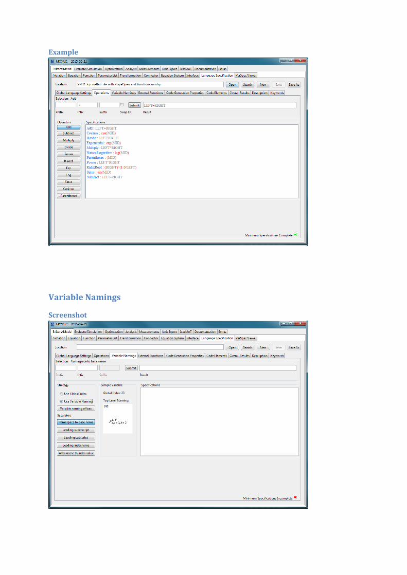
Example
Operations
Screenshot
Options
General remarks:
In the “Operations” panel you define how your user-defined language specification has to generate
the mathematical operations and parentheses. For each of the binary (e.g. multiplication) and unary
(e.g. sine) operators you can set Prefix and Suffix if necessary. Binary operators may also need an
Infix or have to swap the operands. All operators have to be defined (i.e. non-empty) before you
should use your language specification for productive code generation. In the “Specifications“ text
field you can see all operator definitions you have already set.
Operators:
Add
The mathematical addition operation, e.g. “4+5”
Cosine
The mathematical cosine function, e.g. “cos(0)”
Divide
The mathematical division operation, e.g. “4/5”
Exponential
The mathematical exponential function, e.g. “exp(3)”
Multiply
The mathematical multiplication operation, e.g. “4*5”
NaturalLogarithm
The mathematical natural logarithm function, e.g. “ln(1)”
Parentheses
Parentheses, for example “(” and “)”, are used to group the mathematical terms and
numbers to different expressions. Example: “4+(5*6)” vs. “(4+5)*6”
Power
The mathematical power operation, e.g. “53“ (say: “5 to the power of 3”)
RadixRoot
The mathematical n-th root function, e.g. “8(1/3)” (say: “third root of eight”)
Sine
The mathematical sine function, e.g. “sin(0)”
Subtract
The mathematical subtraction operation, e.g. “5-4”
Specification:
Prefix
Character to be put in front of the first operand
Infix
Character to be put between the first and the second operand
Suffix
Character to be put behind the second operand
Swap LR
Check this if you to swap the first and the second operand. This may be interesting for
the radix root operator.
Submit
Press this button to set the prefix, infix, suffix, and swap information of the currently
active operator
Example
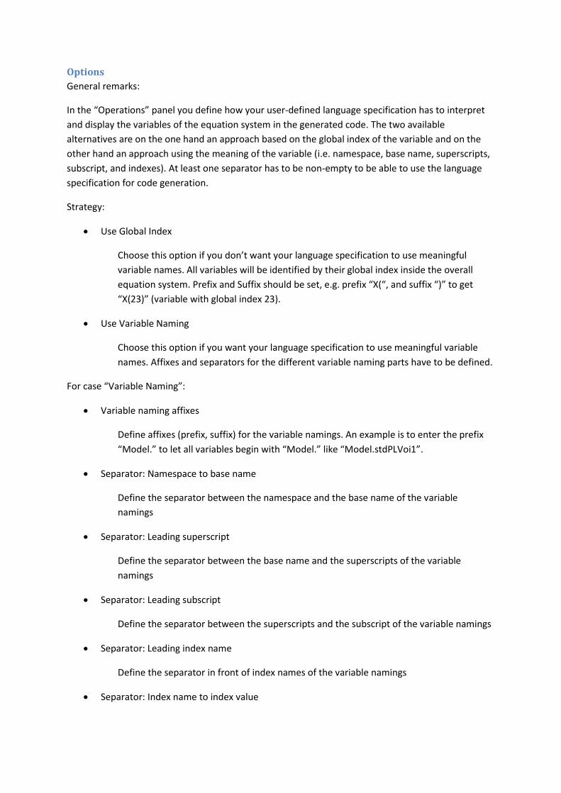
Variable Namings
Screenshot
Options
General remarks:
In the “Operations” panel you define how your user-defined language specification has to interpret
and display the variables of the equation system in the generated code. The two available
alternatives are on the one hand an approach based on the global index of the variable and on the
other hand an approach using the meaning of the variable (i.e. namespace, base name, superscripts,
subscript, and indexes). At least one separator has to be non-empty to be able to use the language
specification for code generation.
Strategy:
Use Global Index
Choose this option if you don’t want your language specification to use meaningful
variable names. All variables will be identified by their global index inside the overall
equation system. Prefix and Suffix should be set, e.g. prefix “X(“, and suffix “)” to get
“X(23)” (variable with global index 23).
Use Variable Naming
Choose this option if you want your language specification to use meaningful variable
names. Affixes and separators for the different variable naming parts have to be defined.
For case “Variable Naming”:
Variable naming affixes
Define affixes (prefix, suffix) for the variable namings. An example is to enter the prefix
“Model.” to let all variables begin with “Model.” like “Model.stdPLVoi1”.
Separator: Namespace to base name
Define the separator between the namespace and the base name of the variable
namings
Separator: Leading superscript
Define the separator between the base name and the superscripts of the variable
namings
Separator: Leading subscript
Define the separator between the superscripts and the subscript of the variable namings
Separator: Leading index name
Define the separator in front of index names of the variable namings
Separator: Index name to index value
Define the separator between the index name and the index value of the variable
namings
Specification:
Prefix
Character to be put in front of an expression
Infix
Character to be put in between two expressions
Suffix
Character to be appended to an expression
Submit
Press this button to set the prefix, infix, and suffix information of the currently active
separator or affix
Example
External Functions
Screenshot
Options
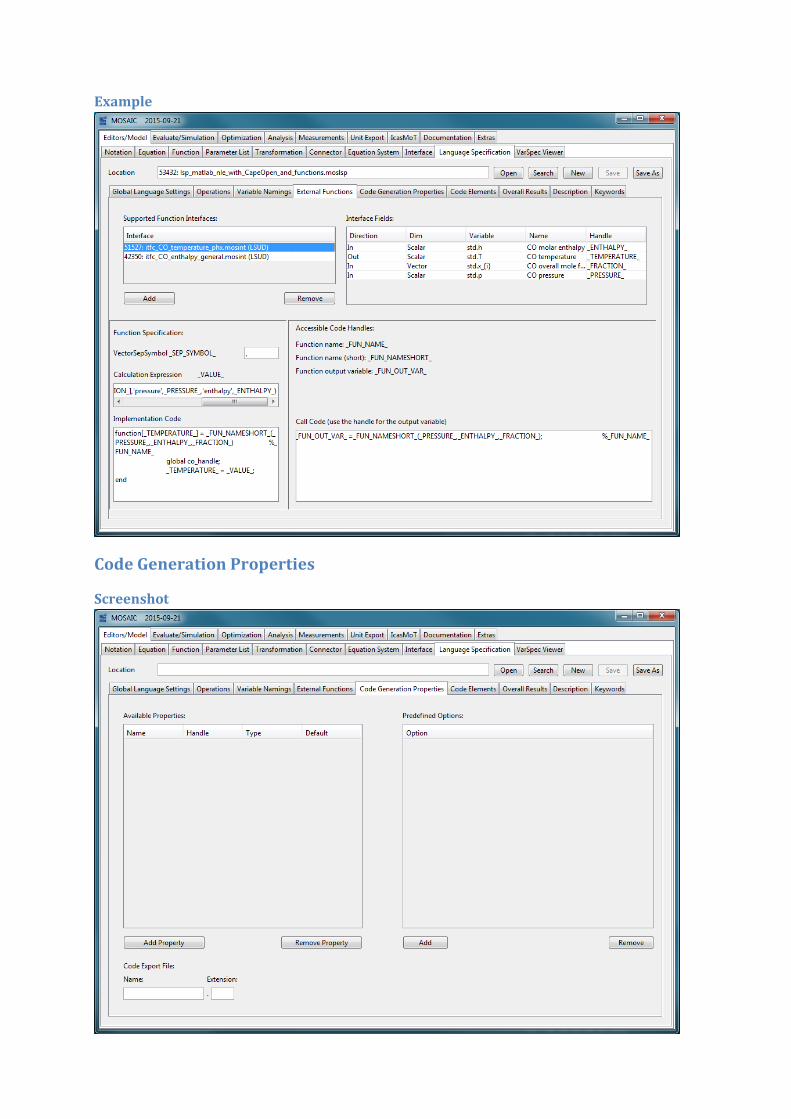
General remarks:
In the “External Functions” panel MOSAIC interfaces can be added as function interfaces supported
by this Language Specificator. Code for MOSAIC functions, that are part of a model and that use a
MOSAIC interface, can this way be generated. In this panel the code to call the function and the code
to implement the function is specified. It has to be remarked that code is actually only generated for
these functions if the “Direct Functions Supported” option in the “Global Language Settings” panel is
checked.
Supported Function Interfaces:
Interface
Name or location of a function interface that has been added as a supported function
interface
Add
Button to add a function interface to the list of supported function interfaces
Remove
Button to remove the selected function interface from the list of supported function
interfaces
Interface Fields:
The table of the interface fields lists all fields that have been specified in the respective MOSAIC
interface. The handle is not specified by the interface and has to be set by the creator of the
Language Specificator
Direction
This is the direction of the field. For function interfaces the possible values are “In” and
“Out”, with exactly one field of direction “out” and an arbitrary number of fields with
direction “in”. The direction can’t be changed here
Dim
This is the dimension of the field. Possible values are “Scalar” and “Vector”. The
dimension can’t be changed here
Variable
This is the name of the field variable as it will be used in generated code. The variable
name can’t be changed here
Name
This is the meaning of the field as it has been stored in the MOSAIC interface. For Cape
Open function interfaces the name are predefined starting with “CO”. The field name
can’t be changed here
Handle
This is the name of the placeholder as it has to be used in the implementation code and
in the call code definition. The handle is not a property of a MOSAIC interface and
therefore has to be set here
Function Specification:
VectorSepSymbol
This is the symbol that is used to separate the different elements of a vector in the generated
code. The handle (placeholder) for the separation symbol is fixed to “_SEP_SYMBOL_”
Calculation Expression
This is the expression that actually calculates the return value of the function. The handle
(placeholder) for this expression is fixed to “_VALUE_”
Implementation Code
This is the full code that is used to define and implement the function in the generated code.
It is recommended to use the above “calculation expression” here, but it is not necessary
Accessible Code Handles:
Some useful code handles (placeholders) have been fixed and are available for the implementation
code and call code.
Function name
This is the full name of the function. The name is fixed by the MOSAIC function that has been
included in the model the code is generated for. The handle (placeholder) is fixed to
“_FUN_NAME_”
Function name (short)
This is the short name of the function. The name is fixed by the id of the MOSAIC function
that has been included in the model the code is generated for. The short name is particularly
useful for programming languages with a limited length of function names like Scilab. The
handle (placeholder) is fixed to “_FUN_NAMESHORT_”
Function output variable
This is the actual function output variable. The output variable is different for each
application (“function call”) of the function. The handle (placeholder) is fixed to
“_FUN_OUT_VAR_”
Function Call:
CallCode
This is the full code that is used to call the function in the generated code. The function call is
used to calculate the value of a variable by calling the function with specific input values. It is
usually necessary to use the handle for the function output variable (“_FUN_OUT_VAR_”)
here to correctly assign the calculation/ function call to the variable to be calculated
Example
Code Generation Properties
Screenshot
Options
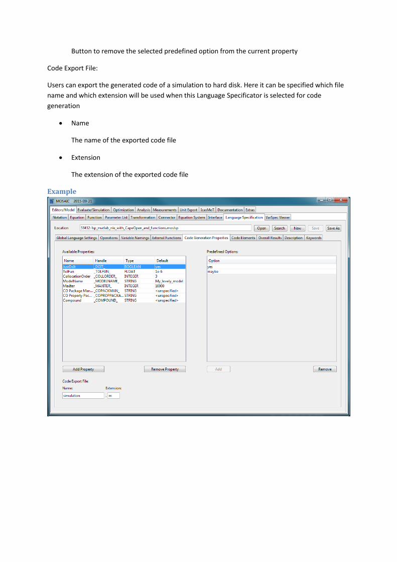
General remarks:
In the “Code Generation Properties” panel options for the code generation can be specified. The
options entered here will be visible to users when the LSUD is loaded in the simulation (evaluation)
using the “Evaluation” tab and the Language Specification section. Typical properties are for example
number of iterations, tolerances, etc. If predefined options are entered for properties here, users will
only be able to select one of these options for code generation.
Available Properties:
Name
The name of the property as it will later be displayed to users selecting this Language
Specificator for code generation
Handle
The identifier of this property as it can be used in the code elements panel. It is the
placeholder where the value of the property will be inserted
Type
The data type of the property. Possible options are Integer, Float (Floating point
number), String, and Boolean (Two-Option-String)
Default
The default value of the property that will be inserted in the generated code if the user
does not specify another value
Add Property
Button to open a dialog to specify a new option including name, handle, type, and
default value
Remove Property
Button to delete the currently selected available property
Predefined Options:
Option
Each entry in this table will be one entry in the combobox in the code generation section
where the code generator and solver properties are set
Add
Button to add a new predefined option to the currently selected property
Remove
Button to remove the selected predefined option from the current property
Code Export File:
Users can export the generated code of a simulation to hard disk. Here it can be specified which file
name and which extension will be used when this Language Specificator is selected for code
generation
Name
The name of the exported code file
Extension
The extension of the exported code file
Example
Code Elements
Screenshot
Options
General remarks:
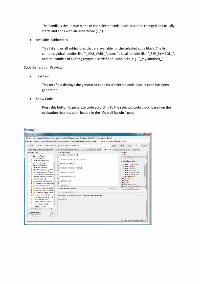
The “Code Elements” panel is the central part of the “Language Specification” editor. In this panel
the elements of the structure of the code to be generated are defined. The code has by definition a
tree structure with a node called “FullCode” as the root node. Each node is a code block. Code blocks
are of different types and can have sub blocks. Blocks without sub blocks are leaves of the tree
structure. Global and local code properties exist and can be accessed in the code blocks. An example
for a global code property is the number of equations in an algebraic equation system
(“_DIM_EQUAS_”). The separator symbol (“_SEP_SYMBOL_”) is an example for a local code property.
The user specifies each code block separately by plain text, thereby using the unique names
(“Handles”) of the properties and of the sub blocks. When the language specification is applied on an
evaluation, all handles will be recursively replaced by the respective property value or code block
specification.
Elements Tree:
Block Tree
The structure of the code is visualized by this tree. Code blocks and properties can be
selected. Information about the selected element will be displayed in the other parts of
this panel
Create Node
Create a new sub block as a child of the currently selected code block. Some predefined
code blocks cannot have children (e.g. “DirectFunctionsCall”)
Delete Node
Remove the select node from the tree structure. All sub blocks will be removed as well
Up
Move the selected node up in the tree structure. The node’s level in the tree is not
changed. The node changes the position with its preceding sibling
Down
Move the selected node down in the tree structure. The node’s level in the tree is not
changed. The nodes changes the position with its subsequent sibling
Block Types:
FullCode
The root code block of the code tree, it can’t be deleted
Block
A simple code block, sub blocks can be added
Differential Variable
A code block to access the differential variable of a (dynamic) system
Direct Functions Impl
A code block for the definition/implementation of functions, contains two sub blocks to
access the input variables and input parameters
Direct Functions Call
A code block to call functions, contains two sub blocks to access the function call
variables and function call parameters
LoopBlocks:
LoopBlocks make collections of system parts accessible in a loop. For each element of the
collection the content of the specification will be generated.
o Namespaces
Loop over the namespaces, contains the short, original, and user-defined
namespace
o Parameters
Loop over the parameters, contains all known variables
o External Parameters
Loop over parameters that have been defined in parameter lists
o Constant Parameters
Loop over all variables that have been fixed as design variables
o EquationsAE (NLE, DAE)
Loop over all algebraic equations
o Variables (NLE)
Loop over all unknown variables
o InputPorts (NLE)
Loop over all input ports, contains a (loop) sub block to access the port variables
o OutputPorts (NLE)
Loop over all output ports, contains a (loop) sub block to access the port
variables
o EquationsODE (ODE, DAE)
Loop over all differential equations
o StateVariablesExplicit (ODE, DAE)
Loop over all explicit states
o StateVariablesImplicit (DAE)
Loop over all implicit states
Input Specification:
Editor
In this editor you can specify the content of the selected block or see a description of the
meaning of the selected system/code property (e.g. “VarsDimension”)
Show Invisible Characters
Check this option to display the invisible characters (whitespaces, tabs and newlines)
CtrStart
In this field you can enter the start value of the counter in loop blocks
Handles:
Handle
The handle is the unique name of the selected code block. It can be changed and usually
starts and ends with an underscore (“_”)
Available Subhandles
This list shows all subhandles that are available for the selected code block. The list
contains global handles like “_DIM_VARS_”, specific local handles like “_SEP_SYMBOL_”,
and the handles of existing (maybe userdefined) subblocks, e.g. “_MySubBlock_”.
Code Generation Preview:
Text Field
This text field displays the generated code for a selected code block if code has been
generated
Show Code
Press this button to generate code according to the selected code block, based on the
evaluation that has been loaded in the “Overall Results” panel
Example
Overall Results
Screenshot
Options
General Remarks:
In the “Overall Results” panel you load an evaluation to test the code generation of your language
specification. You need to load an evaluation in this panel to activate the “Generate Full Code”
button and to be able to generate code for the different code blocks in the “Code Elements” panel.
Load File:
Evaluation
Like in other editors of MOSAIC you can use Unload, Reload, Search and Select to set (or
unset) a model element. In this case an evaluation can be loaded to test the code generation
with your language specification.
Status Information:
Text Field
This text field displays status information about the evaluation. It is the same as in the
“Evaluate” panel of the “Evaluate/Simulation” section of MOSAIC
Code:
Text Field
This text field displays the generated code if code has been generated
Generate Full Code
Press this button to generate code according to your user-defined language specification and
based on the evaluation that has been loaded before
Example
Description This “Description” panel is the same as in all the other MOSAIC editors. You should use it to give a
detailed explanation on how to use your user-defined language specification. The description will be
displayed in the code generation panel of the Evaluate/Simulation section of MOSAIC. Of course you
can also add additional documentation files to this Language Specification by using the file upload
and attachment possibilities.
Keywords This “Keyword” panel is the same as in all the other MOSAIC editors. You can add keywords to this
Language specification to attach some meta-information. Possible appropriate keywords may
describe the type of models this language specification can be applied (algebraic/NLE, or ODE, or
DAE) or the programming language family (Fortran, C/C++, Matlab, …). This information can later on
be used to filter the language specifications when it comes to opening in this editor or loading in
other editors.
Tips, Tricks &Workflow Suggestions
Documentation A language specification, without good instructions how to use it, is worthless for people who
haven’t designed it themselves. So you should for example explicitly mention which type of equation
systems (AE/NLE, ODE, DAE) you support with your language specification by writing it down in the
description and by using keywords.
Re-Use If most of the work already has been done – don’t do it again. So re-use what has been done before
by opening a specification and saving it as another language specification to be modified in the next
step. It makes sense to copy language specifications supporting the same type of equation systems
you want to support or by selecting a language specification that will create code for the same
programming language you are targeting.
Have a code structure in mind (and on paper) before starting Don’t start building the code structure just “from brain to screen”, use a structure you have written
down on paper. The code blocks you create always have a tree structure with the “FullCode” block
being the root. It is up to you how fine-grained you separate the different parts of your code tree, i.e.
how many levels your tree has. I nevertheless propose to design smaller, hierarchically ordered
blocks in contrast to a few very big code blocks in one level. This will later on not only help you when
it comes to systematically improving and extending the code structure (meaningful names of the
code blocks help a lot!). Smaller blocks also help when it comes to debugging, because the code
preview functionality allows you to check each block separately.
Typical Workflow
Before creating a new LSUD:
1. Choose the targeted programming language, e.g. python
2. Choose the type of equation system you want to support, e.g. NLE/AE
3. Look for an already existing LSUD for the same programming language and the same type of
equation system. If you are successful: Load this LSUD (A) and save it as another LSUD (B).
This way you have write access (B) and you do not change the existing LSUD (A) by accident
(in case you have write access to A, too).
Creating the new LSUD:
1. If possible: Open the “prepared” LSUD (B)
2. Check or set the System Type (DAE, ODE, NLE)
3. Check or redefine the operators
4. Check or redefine the Variable Naming settings (Affixes, Separators)
5. Enter a description in the Description Tab
6. Select keywords in the Keywords Tab
7. Build the code block tree in the “Code Elements” Panel
8. Don’t forget to click on “Save” when you made progress
9. Add support for External Functions if necessary
10. Set the name and extension for the export file
11. Define properties and their options for code generation
Testing and Using the LSUD:
1. Load an evaluation in the “Overall Results” panel, click on “Generate Full Code”, and check
the result.
2. In the “Code Elements” panel: Select a code block and click on “Show Code” (needs a loaded
evaluation, see “Overall Results” panel)
3. In the “Evaluate/Simulation” section, when it comes to code generation (“Evaluation” tab),
activate “User-defined Language Specification”, and click on “Select” or “Search” to choose
your own language specification for code generation.