21
Technical Data and Dimensional Data Sheet for AUMA India Gearboxes GS 40.2 - GS 500 GF 63.2 - GF 315 GS 40.2 - GS 500 GK 10.1 - GK 40.1 ABG 10.2 - ABG 35.2

Technical Data and
Dimensional Data Sheetfor
AUMA India Gearboxes
GS 40.2 - GS 500GF 63.2 - GF 315GS 40.2 - GS 500GK 10.1 - GK 40.1ABG 10.2 - ABG 35.2
Table of Contents: Gearbox - Technical & Dimensional Data Sheets
Note: There are various features and options that are available other than what is listed in the catalogue. For special needs, please contact AUMA India.
Armaturen-UndMaschinen-Antriebe
34-36
32-33
31
GS 40.2 - GS 125.2
GS 160 - GS 250
GS 315 - GS 500
25
27
26
Technical Data sheet for Part-turn Worm Gearboxes
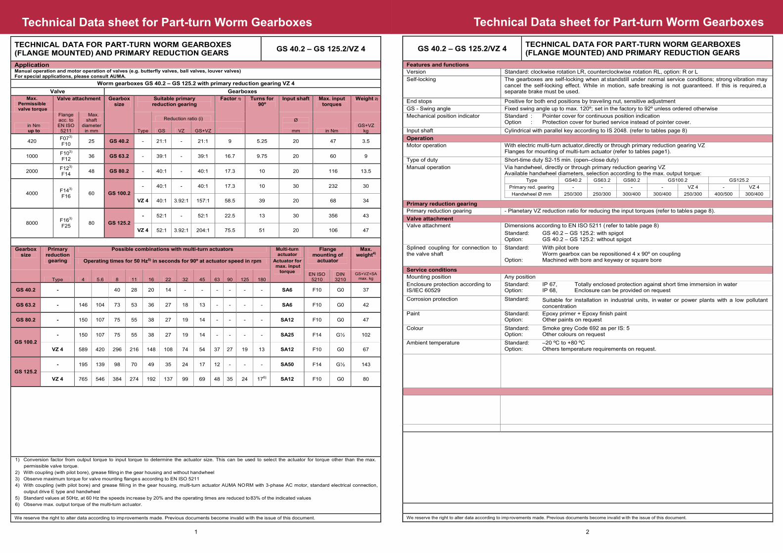
GS 40.2 – GS 125.2/VZ 4 TECHNICAL DATA FOR PART-TURN WORM GEARBOXES (FLANGE MOUNTED) AND PRIMARY REDUCTION GEARS
Features and functions
Version Standard: clockwise rotation LR, counterclockwise r o t a t i o n R L , o p t i o n : R o r L
Self-locking The gearboxes are self-locking when at s t a n d s t i ll u n d e r n o r m a l s e rvice conditions; strong vibration may cancel the self-locking effect. While in motion, safe b r eaking is not guaranteed. If this is required , a separate brake must be used.
End stops Positive for both end positions by trave li n g n u t , s e n s i t iv e a d j u s t m e nt
GS - Swing angle Fixed swing angle up to max. 120º; s e t i n t h e f a c t o r y t o 9 2º unless ordered otherwise
Mechanical position indicator Standard : Option :
Pointer cover for continuous position indication Protection cover for buried service instead of pointer cover.
Input shaft Cylindrical with parallel key according t o I S 2 0 4 8 . ( r e f e r t o t a b l e s page 8)
Operation
Motor operation With electric multi-turn actuator, d ir e c t l y o r t h r o u g h p r imary reduction gearing VZ Flanges for mounting of multi-turn actuator (refer to tables page1).
Type of duty Short-time duty S2-15 min. (open–close d u t y )
Manual operation Via handwheel, directly or through p r im a r y r e d u c t i o n g e aring VZ Available handwheel diameters, selection according to the max. output torque:
Type GS40.2 GS63.2 GS80.2 GS100.2 GS125.2
Primary red. gearing - - - - VZ 4 - VZ 4
Handwheel Ø mm 250/300 250/300 300/400 300/400 250/ 3 0 0 4 0 0 / 5 0 0 3 00/400
Primary reduction gearing
Primary reduction gearing - Planetary VZ reduction r a tio for reducing the input torques (refer to tables page 8).
Valve attachment
Valve attachment Dimensions accord i n g t o E N I S O 5 2 1 1 ( refer to table page 8)
Standard: Option:
GS 40.2 – GS 125.2: with spigot GS 40.2 – GS 125.2: without spigot
Splined coupling for connection to the valve shaft
Standard:
Option:
With pilot bore Worm gearbox can be repositioned 4 x 90º on coupling Machined with bore and keyway or square bore
Service conditions
Mounting position Any position
Enclosure protection according to IS/IEC 60529
Standard: Option:
IP 67, Totally enclosed protection against short time immersion in water IP 68, Enclosure can be provided on request
Corrosion protection Standard: Suitable for installation in industrial units, in w ater or power plants with a low pollutant concentration
Paint Standard: Option:
Epoxy primer + Epoxy finish paint Other paints on request
Colour Standard: Option:
Smoke grey Code 692 as per IS: 5 Other colours on request
Ambient temperature Standard: Option:
–20 ºC to +80 ºC Others temperature requirements on request.
We reserve the right to alter data according to imp rovements made. Previous documents become invalid w ith the issue of this document.
2
Technical Data sheet for Part-turn Worm Gearboxes
TECHNICAL DATA FOR PART-TURN WORM GEARBOXES (FLANGE MOUNTED) AND PRIMARY REDUCTION GEARS
GS 40.2 – GS 125.2/VZ 4
Application Manual operation and motor operation of valves (e.g. butterfly valves,
ball valves, louver valves)
For special applications, please consult AUMA.
Worm gearboxes GS 40.2 – GS 125.2 with primary reduction gearing VZ 4
Valve Gearboxes
Max.
Permissible valve torque
Valve attachment
Gearbox size
Suitable primary
reduction gearing Factor 1)
Turns for
90º Input shaft
Max. input torques
Weight 2)
in Nm up to
Flange acc. to EN ISO
5211
Max. shaft
diameter in mm Type
Reduction ratio (i) Ø
mm in Nm GS+VZ
kg GS VZ GS+VZ
420
F073)
F10 25 GS 40.2 - 21:1 - 21:1 9 5.25 20 47 3.5
1000 F103)
F12 36 GS 63.2 - 39:1 - 39:1 16.7 9.75 20 60 9
2000 F123)
F14 48 GS 80.2 - 40:1 - 40:1 17.3 10 20 116 13.5
4000 F143)
F16
60 GS 100.2
- 40:1 - 40:1 17.3 10 30 232 30
VZ 4 40:1 3.92:1
157:1 58.5 39 20 68 34
8000 F163)
F25
80 GS 125.2
- 52:1 - 52:1 22.5 13 30 356 43
VZ 4 52:1 3.92:1
204:1 75.5 51 20 106 47
Gearbox size
Primary reduction gearing
Possible combinations with multi-turn actuators
Multi-turn actuator
Flange
mounting of actuator
Max. weight4)
Operating times for 50 Hz5)
in seconds for 90º at actuator speed in rpm
Actuator for
max. input torque
Type 4 5.6 8 11 16 22 32 45 63 90 125 180 EN ISO
5210 DIN 3210
GS+VZ+SA max. kg
GS 40.2 - 40 28 20 14 - - - - - - SA6 F10 G0 37
GS 63.2 - 146 104 73 53 36 27 18 13 - - - - SA6 F10 G0 42
GS 80.2 - 150 107 75 55 38 27 19 14 - - - - SA12 F10 G0 47
GS 100.2
- 150 107 75 55 38 27 19 14 - - - - SA25 F14 G½ 102
VZ 4 589 420 296 216 148 108 74 54 37 27 19 13 SA12 F10 G0 67
GS 125.2
- 195 139 98 70 49 35 24 17 12 - - - SA50 F14 G½ 143
VZ 4 765 546 384 274 192 137 99 69 48 35 24 176) SA12 F10 G0 80
1) Conversion factor from output torque to input tor q u e to determine the actuator size. This can be use d to select the actuator for torque other than the m ax.
permissible valve torque.
2) With coupling (with pilot bore), grease filling i n the gear housing and without handwheel
3) Observe maximum torque for valve mounting flange s according to EN ISO 5211
4) With coupling (with pilot bore) and grease filli n g in the gear housing, multi-turn actuator AUMA NO R M with 3-phase AC motor, standard electrical connec t ion,
output drive E type and handwheel
5) Standard values at 50Hz, at 60 Hz the speeds inc r e ase by 20% and the operating times are reduced to 83% of the indicated values
6) Observe max. output torque of the multi-turn act u ator.
We reserve the right to alter data according to imp rovements made. Previous documents become invalid w ith the issue of this document.
1

GS 160 – GS 250/GZ TECHNICAL DATA FOR PART-TURN WORM GEARBOXES (FLANGE MOUNTED) AND PRIMARY REDUCTION GEARS
Features and functions
Version Standard: clockwise rotation LR, counterclockwise r o t a t i o n R L , o p t i o n : R o r L
Self-locking The gearboxes are self-locking when at s t a n d - s t i l l u n d e r n o r m a l s ervice conditions; strong vibrations may cancel the self-locking effect. While in motion, safe breaking is not guaranteed. If this is requir e d , a separate brake must be used
End stops Positive for both end positions by trave l i n g n u t , s e n s i t i v e a d ju s t m e nt
GS - Swing angle Fixed swing angle up to max. 135º; s e t i n t h e f a c t o r y t o 90º unless ordered otherwise
Mechanical position indicator Standard: Option:
Pointer cover for continuous position indication Protection cover for buried service instead of pointer cover
Input shaft Cylindrical with parallel key according t o I S 2 0 4 8 . ( r e f e r t o t a b l e p age1)
Operation
Motor operation With electric multi-turn actuator, d i r e c t l y o r t h r o u g h p r imary reduction gearing GZ Flanges for mounting of multi-turn actuator (refer to table page 1)
Type of duty Short-time duty S2-15 min (open-close d u t y )
Manual operation Via handwheel, directly or through p r i m a r y r e d u c t io n g e aring GZ Available handwheel diameters, selection according to the max. output torque:
Type GS 160 GS 200 GS 250
Primary red. gearing - GZ 14 - GZ 16 - GZ 25
Handwheel Ø mm 640/800
400 300 - 500/640
400 300 - 800 500/640
400
Primary reduction gearing
Primary reduction gearing - Spur gear with various r e d u c t i o n r a tios for reducing the input torques (refer to tables page 12). - Combination with GK bevel gearbox directly on GS with GZ possible.
Valve attachment
Valve attachment Dimensions accor d i n g t o E N I S O 5 2 1 1 (refer to table page12)
Standard: GS 160 – GS 250: with spigot GS 160 – GS 250: without spigot
Splined coupling for connection to the valve shaft
Standard:
With pilot bore Worm gearbox can be repositioned 4 x 90º on coupling Including grub screw for fixing to valve shaft
Option: Machined with bore and keyway or squar e bore
Service conditions
Mounting position Any position
Enclosure protection according to IS/IEC 60529
Standard: Option:
IP 67, Totally enclosed protection against short time immersion in water IP 68, Enclosure can be provided on request
Corrosion protection Standard: Suitable for installation in industrial units, in water or power plan ts with a low pollutionconcentration
Paint Standard: Option:
Epoxy primer + Epoxy finish paint Other paints on request
Colour Standard: Option:
Smoke Grey Code 692 as per IS: 5 Other colours on request
Ambient temperature Standard: Option:
–20 ºC to +80 ºC Others temperature requirements on request.
We reserve the right to alter data according to imp rovements made. Previous documents become invalid w ith the issue of this document.
Technical Data sheet for Part-turn Worm Gearboxes
4
TECHNICAL DATA FOR PART-TURN WORM GEARBOXES(FLANGE MOUNTED) AND PRIMARY REDUCTION GEARS
GS 160 – GS 250/GZ
Application
Manual operation and motor operation of valves (e.g. butterfly valves, ball valves, louver valves) For special applications, please consult AUMA.
Worm gearboxes GS 160 – GS 250 with primary reduction gearing GZ 14 – GZ 25
Valve Gearboxes
Max. Permissible valve torque
Valve attachment Gearbox size
Suitable primary
reduction gearing Factor 1) Turns for
90º Input shaft Max. input
torques Weight 2)
in Nm up to
Flange acc. to EN ISO
5211
Max. shaft
diameter in mm Type
Reduction ratio (i) Ø
mm in Nm GS+GZ
kg GS GZ GS+GZ
14000 F253)
F30 100 GS 160
- 54:1 - 54:1 24.2 13.5 30 579 85
GZ 14 54:1 4:1 216:1 82 54 30/(20) 171 106
54:1 8:1 432:1 164 108 20 86 106
28000 F303)
F35 125 GS 200
- 53:1 - 53:1 23.9 13.25 40 1172 150
GZ 16
53:1 4:1 212:1 82 53 30 342 180
53:1 8:1 424:1 163 106 30/(20) 172 180
53:1 16:1 848:1 320 212 20 88 180
56000 F353) F40
160 GS 250
- 52:1 - 52:1 23.4 13 50 2394 290
GZ 25
52:1 4:1 208:1 80 52 40/(30) 700 325
52:1 8:1 416:1 160 104 30 350 325
52:1 16:1 832:1 320 208 30/(20) 175 325
Gearbox size
Primary reduction gearing
Possible combinations with multi- Multi -turn
Actuator Flange
mounting of actuator
Max. weight 4)
Operating times for 50 Hz 5) in seconds for 90º at actuator speed in rpm Actuator for Max. input
torque
Type 4 5.6 8 11 16 22 32 45 63 90 125 180
EN ISO 5210
DIN 3210
GS+GZ+SA max. kg
GS 160
- 203 145 102 74 51 37 25 18 - - - - SA60 F14 G½ 185
GZ 14 (4:1) 810 579 405 295 204 148 102 72 51 36 25 18 SA25 F14 G½ 178
GZ 14 (8:1) - - 810 589 405 296 204 144 102 72 51 36 SA12 F10 G0 139
GS 200
- 199 142 100 72 50 35 25 18 - - - - - F25 - 300
GZ 16 (4:1) 795 568 398 288 200 144 100 72 50 36 25 18 SA50 F14 G½ 280
GZ 16 (8:1) - - 795 578 398 288 200 144 100 72 50 36 SA25 F14 G½ 252
GZ 16 (16:1) - - - - 795 578 398 288 200 144 100 72 SA12 F10 G0 213
GS 250
- 195 139 98 71 49 35 24 - - - - - - F30 - 480
GZ 25 (4:1) 780 557 390 284 196 140 98 70 49 35 24 17 SA100 F16 G3 456
GZ 25 (8:1) - - 780 567 392 280 196 140 98 70 48 35 SA50 F14 G½ 425
GZ 25 (16:1) - - - - 780 567 392 280 196 140 98 70 SA25 F14 G½ 397
1) Conversion factor from output torque to input to r q u e to determine the actuator size. This can be use d to select the actuator for torque other than the m ax. permissible valve torque
2) With coupling (with pilot bore), grease filling i n the gear housing and without handwheel 3) Observe maximum torque for valve mounting flanges a ccording to EN ISO 5211 4) With coupling (with pilot bore) and grease filling i n the gear housing, multi-turn actuator AUMA NOR M with 3-phase AC motor, standard electrical connec t ion,
output drive E type and handwheel 5) Standard values at 50Hz, at 60 Hz the speeds inc r e ase by 20% and the operating times are reduced to 83% of the indicated values
We reserve the right to alter data according to imp rovements made. Previous documents become invalid w ith the issue of this document.
turn actuators
Technical Data sheet for Part-turn Worm Gearboxes
3

Technical Data sheet for Part-turn Worm Gearboxes
GS 315 -
GS 500
with GZ 30 – GZ 40
TECHNICAL DATA FOR PART-TURN WORM GEARBOXES(FLANGE MOUNTED) AND PRIMARY REDUCTION GEARS
Features and functions
Version Standard: clockwise rotation LR, counterclockwise rotation RL, option: R or L
Self-locking The gearboxes are self-locking when at standstill under normal service conditions; strong vibrations may cancel the self-locking effect. While in motio n , safe breaking is not guaranteed. If this is required, a separate brake must be used.
End stops Adjustable end stops by travelling nut
Swing angle Standard : Adjustable 0° - 135º; set in the factory t o 92º unless ordered otherwise.
Option : Swing angle > 100°, multi-turn versi o n without end stops, GSD version
Mechanical position indicator Standard : Options :
Pointer cover for continuous position indication Protection cover for buried service instead of pointer cover.
Input shaft Cylindrical with parallel key according to IS 2048 (refer to tables on page 18)
Operation
Motor operation With electric multi-turn actuator, d i r e c t l y o r t h r o u g h p r i m a r y r e d u c tion gearing GZ. Flanges for mounting of multi-turn actuator (refer to tables on page 18)
Type of duty Short-time duty S2-15min. (open-close duty)
Manual operation Via handwheel, directly or through p r i m a r y r e d u c t i o n g e a r in g G Z Available handwheel diameters, selection according to the max. output torque:
Type GS 315 GS 400 GS 500
Primary red. gearing - GZ 30 - GZ 35 - GZ 40 GZ 40 /GZ 16
Reduction ratio - 8:1 16:1 32:1 - 8:1 16:1 32:1 - 16 : 1 3 2 : 1 6 4 : 1
Hand wheel Ø mm - 800 500/ 640
400 - - 800 500/ 640
- - 800 500/ 640
Primary reduction gearing
Primary reduction gearing - Type GZ as spur gear wi t h v a r i o u s r e d u c t i o n r a t i o s for reducing the input torques. (refer to tables page 18) - Combination with GK bevel gearbox directly on GS or on GS with GZ possible.
Valve attachment
Valve attachment Dimensions according to EN ISO 521 1 ( r e f e r t o t a b l e s o n p a g e 1 8 ) . Standard : Optional :
GS315 – GS500 with spigot GS315 – GS500 without spigot
Splined coupling for connection to the valve shaft
Standard :
Options :
With pilot bore Worm gearbox can be repositioned 4 x 90º on coupling Including grub screw for fixing of valve shaft Machined with bore and keyway, square bore or bore with two-flats.
Service conditions
Mounting position Any position
Enclosure protection according to IS/IEC 60529 Standard : Options :
IP 67 Totally enclosed protection against short time immersion in water IP 68 Enclosure can be provided on request
Corrosion protection Standard : Suitable for instal l a t io n i n i n d u s t r i a l u n i t s , i n w a t e r o r power plants with a low pollutant concentration
Paint Standard : Option :
Epoxy primer + Epoxy finish paint Other paints on request
Colour Standard : Option :
Smoke Grey, Code 692 as per IS: 5 Other colours on request
Ambient temperature Standard : Option :
– 20 ºC to + 80 ºC Others temperature requirements on request.
We reserve the right to alter data according to imp rovements made. Previous documents become invalid w ith the issue of this document.
6
Technical Data sheet for Part-turn Worm Gearboxes
TECHNICAL DATA FOR PART-TURN WORM GEARBOXES(FLANGE MOUNTED) AND PRIMARY REDUCTION GEARS
GS 315 -
GS 500
with GZ 30 – GZ 40
Application
For motor or manual operation of valves (e.g. butterfly valves, ball valves, louver valves) For special applications, please consult AUMA
Worm gearboxes GS 315 - GS 500 with primary reducti on gearing GZ 30 – GZ 40
Type
Output torques (Nm) / Valve mounting flange – EN ISO 5211
Valve
attachment
Suitable primary reduction gearing
Input torques
Turns
for Factor 2)
Input shaft
Weight 3)
Max. shaft Ø
mm
Reduction ratio (i) at output torque of Ø
mm GS/+GZ
kg Option - 1
Nm Option - 2
Nm Type GS GZ GS+ GZ
100% Nm
140% Nm
GS 315 63000 / F40 90000 / F48 200
- 53:1 - 53:1 2636 3766 13.25 23.9 60 520
GZ 30
53:1 8:1 424:1 389 556 106 162 30
630 53:1 16:1 848:1 194 277 212 325 30
53:1 32:1 1696:1
97 138 424 650 20
GS 400 125000 / F48 180000 / F60
250
- 54:1 - 54:1 5144 7407 13.5 24.3 80 980
GZ 35
54:1 8:1 432:1 758 1091 108 165 40
1100 54:1 16:1 864:1 379 545 216 330 30
54:1 32:1 1728:1
189 273 432 660 30
GS 500 250000 / F60 360000 / -1)
315
- 52:1 - 52:1 10684 15385 13 23.4 100 1800
GZ 40 52:1 16:1 832:1 781 1125 208 320 40
2000 52:1 32:1 1664:1
391 563 416 640 30
GZ 40/ GZ 16
52:1 64:1 3328:1
218 314 832 1147 30 2030
Possible combinations with multi-turn actuators
Gearbox
Primary reduction gearing
Flange for mounting
of actuator
Perm. actuator weight Option-1
Suitable
AUMA multi-turn
actuator for
Perm. actuator weight
Option-2
Suitable
AUMA multi-turn
actuator for
Operating times for 50 Hz 6)
in seconds for 90º at actuator speed in rpm
Type Type EN ISO
5210 DIN 3210
max. Kg
Option-1 output torque
max. Kg
Option-2 output torque
16 22 32 45 63 90 125 180
GS 315
- F30 - 400 SA30.1 400 SA30.1 50 36 25 - - - - -
GZ30 (8:1) F14 G½ 99 SA50 99 SA60 - 289 199 141 101 71 517) 357)
GZ30 (16:1)
F14 G½ 71 SA25 71 SA30 - - - 283 202 141 1027) 717)
GZ30 (32:1)
F10 G0 33 SA12 - - - - - - - 283 2047) 1417)
GS 400
- F35 - 800 SA35.1 800 SA35.1 51 37 25 - - - - -
GZ35 (8:1) F16 G3 131 SA100 131 SA1007)
- 296 203 144 103 72 527) 367)
GZ35 (16:1)
F14 G½ 99 SA50 99 SA60 - - - 288 206 144 1047) 727)
GZ35 (32:1)
F14 G½ 71 SA25 71 SA30 - - - - - 288 2077) 1447)
GS 500
- F40 - 1000 SA40.1 1000 SA40.1 49 35 24 - - - - -
GZ40 (16:1)
F16 G3 131 SA100 131 SA1007)
- - 390 277 198 139 1007) 697)
GZ40 (32:1)
F14 G½ 99 SA50 99 SA60 - - - - - 277 2007) 1397)
GZ40/GZ16 (64:1)
F14 G½ 71 SA25 99 SA50 - - - - - - 3997) 2777)
1) Valve mounting flange size beyond EN ISO 5211 standard, p lease consult AUMA. 2) Conversion factor from output torque to input to r q ue to determine the actuator size. This can be us e d to select the actuator for torque other than the max. permissible
valve torque. 3) With coupling (pilot bore), grease filling in th e gear housing and without hand wheel 4) Standard values at 50 Hz. At 60 Hz the speed incr e ases by 20% and the operating times are reduced t o 83% of the indicated values. 5) Observe max. output torque of the multi-turn act u ators.
We reserve the right to alter data according to imp rovements made. Previous documents become invalid w ith the issue of this document.
5

Dimension sheet for Part-turn Gearboxes
Dimensions
EN ISO 5211 F07 F10 F10 F12 F12 F14 F14 F16 F14 F16 F16 F25 F16 F25
A
B1
B2
C
D
E
E1
F
H 89 97 100 116 124 144 150 176 150 176 163 173 163 173
I
J 50 58 56 72 70 90 84 110 84 110 93 103 93 103
K
L 40 51 65 81 75 95 90 116 90 116 105 115 105 115
L1
M
M1
Ø N
Ø O max
Ø O Pilot bore
P1)
Q1)
R
25
15
8
28.3
105
4
13
8
20
M4
41.8
M6
60
M8 M8
64.4
5 5
12 12 15 15 15 15
147 156
159 165 223 262
18 1815
77 95 113 113
220 220
127 133 185 185
127
118
96 113 149
85
85
92
92
63 80 100 100 125 125
GS 63.2 GS 80.2 GS 100.2 GS 100.2 + VZ 4
GS 40.2 - GS 125.2/VZ 4
GS 125.2 GS 125.2 + VZ 4GS 40.2
143
195 195
230 230
16
5 5
16 16
274
174 174
127
118
138
128
138
128
143
149
65 65
51.8 67.6 81.6 81.6 105.8
M8
53 53
80 80
22 22
30
10 14 18 18
105.8
35 40
36 48 60
85.4 85.4
174 -
39.3 51.8
118 125 163 -
64.4
M8
120
20 25 25 25 30
234
4 4
M6
145
40
72
72
73
56
113
R
R1
T
U PCD
W
X max 5 8 10 10 20 20 20 20 20 20 30 30 30 30
X min 0 0 0 0 0 0 0 0 0 0 0 0 0 0
Øa f7
b
c
Ø d1 90 125 125 150 150 175 175 210 175 210 210 300 210 300
Ø d2 f8 55 70 70 85 85 100 100 130 100 130 130 200 130 200
Ø d3 70 102 102 125 125 140 140 165 140 165 165 254 165 254
Ø d4 M8 M10 M10 M12 M12 M16 M16 M20 M16 M20 M20 M16 M20 M16
h 3 3 3 3 3 3 3 3 3 3 3 5 3 5
h1 15 17 15 18 18 24 24 30 24 30 30 24 30 24
I - max 75 86 85 101 105 125 130 156 130 156 140 150 140 150
t 22.5
M5
70
-
20
6
40
105
-
Mounting flange
for
multi-turn actuator
ISO 5210
DIN 3210
Ø d5
Ø d6 H8
Ø d7
Ø d8
h3
S
5
17
F14
G½
175
100
140
18
10
-
G0
125
60
102
11
5
10
-
125
70
102
11
5
F07
-
90
55
9
4
8
F10
70
22.5 22.5 33 22.5 33 22.5
174 -118 125 163 -
-
M6 M6
222- - 234-
125
M6 M6 M6 M6
150
20
8 6
- - - 218 - 228
20 20 20 30
15090 110 125
30
60 40
86
40 40 60 40
6 6
S 1710 10
We reserve the right to alter data according to improvements made. Previous documents become invalid with the issue of this document.
8
DIMENSIONS WORM GEARBOX - FLANGE MOUNTED
8
DIMENSIONS PART-TURN WORM GEARBOX
- FLANGE MOUNTED
Dimension sheet for Part-turn Worm Gearboxes
7

Dimension Data sheet for Part-turn Worm Gearboxes
Dimensions
EN ISO 5211
A
C
D
E
F
H
I
J
K
L
M
L1
M1
Ø N
Ø O max
Ø O - Pilot bore
P1)
Q1)
R
268
266
134
180
105
173 215
420
160 200 250
248 305 400
340 400 490
40
100
32
50
340
25
27
40
20
M12 M16
60
32
25
30
125
140
20
28
20
20
169.4
320
35
160
200
F30 F35
70
M10
70
140
180
94
F35
GS 250
106.4 132.4
260
F40
165
76
110
260
149.2 189
F25 F30
GS 160 - GS 250
GS 160 GS 200
94
194
105
138
249210
101
209
R
S
T
Ø U PCD
X min
X max
Øa g6
b
Ø d1
Ø d2 f8
Ø d3
Ø d4
Ø d5
Ø d6 H8
Ø d7
Ø d8
h
h1
h3
I - max
m
DIN 5480 'n'
q
t
120 149 160 199
53.533
210
150 x 3 x 48 190 x 5 x 36 210 x 5 x 40
50
43
7
175
0
25
230
18
320
406
14
M30
300
22
300
260
M36
254
12
0
356
0
260
40
M10 X 18
5
200
356
100
M20
298
5
-
37
475
12
415
200
33
M8 X 15
185
M10 X 15
40
298
M20
415
260
M30
5
300
22
M6 X 10
8
350
230
345
40 50
260
30
350
30
M6 X 10 M8 X 13
18 22
50 67
25
200
- -
-
5
85
10 - -
140
M16
5
30
230
345
We reserve the right to alter data according to improvements made. Previous documents become invalid with the issue of this document.
DIMENSIONS WORM GEARBOX - FLANGE MOUNTED
10
Dimension Data sheet for Part-turn Worm Gearboxes
DIMENSIONS WORM GEARBOX
- FLANGE MOUNTED
9

Dimension Data sheet for Part-turn Worm Gearboxes
Dimensions
GZ Ratio (i)
EN ISO 5210
DIN 3210
EN ISO 5211 F25 F30 F25 F30 F30 F35 F30 F35 F30 F35 F35 F40 F35 F 4 0 F 3 5 F 4 0
A
B
C
D
E
G
H 165 194 165 194 210 249 210 249 210 249
I
J 76 105 76 105 101 140 101 140 101 140
K
L 110 138 110 138 140 180 140 180 140 180
M
Ø N
L1
M1
Ø O max
Ø O Pilot bore
200 250
G3 G½G½
266
G½G½
248
173
294
16:1
F14 F10 F14 F14
G0
160
F16 F14 F14
G0 G½
GS 160/GZ 14 - GS 250/GZ 25
GS 160/GZ 14 GS 200/GZ 16
4:1 8:1 8:1 8:14:1 16:1 4:1
GS 250/GZ 25
F10
627 627 (607)
305 400
465 (445) 445
340 400 490
545 545 (525) 525 647 (627)
149.2 189 209
215 268
70 94 105
324 324
25 27 35
M16
100
134
20 25 30
180
20 20 20
40 50
M10 M12
125 160
60Ø O Pilot bore
P1)
Q1)
R1
T
Ø U PCD
V
W
X min - max
Øa g6
c
Ø d1 300 345 300 345 350 415 350 415 350 415 415 475 415 475 415 475
Ø d2 f8 200 230 200 230 230 260 230 260 230 260 260 300 260 300 260 300
Ø d3 254 298 254 298 298 356 298 356 298 356 356 406 356 406 356 406
Ø d4 M16 M20 M16 M20 M20 M30 M20 M30 M20 M30 M30 M36 M30 M36 M30 M36
e
h 5 5 5 5 5 5 5 5 5 5 5 7 5 7 5 7
h1 25 30 25 30 30 40 30 40 30 40 40 50 40 50 40 50
l max 120 149 120 149 160 199 160 199 160 199
DIN 5480 'n'
q
lbs
F10 20 6 125 70 102 11 4 40 22.5 12 2.2
- 20 6 125 60 102 11 4 40 22.5 12 2.2
F14 30 8 175 100 140 18 5 60 33 17 5
F16 40 12 210 130 165 22 6 80 43 25 11
60 / (43) 43 60 60 / (43) 43 73 / (60) 60
100 115 115
200 230 230
60 / (43)
0 - 12 0 - 22
M6 X 10 M8 X 15 M10 X 15
185
30
230 260
0 - 22
30 30 / (20) 20 40 / (30)
106.4
Mounting flanges for multi-turn actuator
1
Ød6 H8
G3
z1
5
Ød7 Ød8
-
G0
G½
t s
30 / (20)
WeightEN ISO 5210 DIN 3210 Øa g6 b Ød5 h3
kg
1
2.3
40
132.4 169.4
28 32
38 55 55 / (38)
40 50
405 485 567
55 55 / (38)
60
30 / (20) 20
38 65 / (55)
M6 X 10 M8 X 13 M10 X 18
200
150 X 3 X 48 190 X 5 X 36 210 X 5 X 40
55 / (38)
F16 40 12 210 130 165 22 6 80 43 25 11
We reserve the right to alter data according to improvements made. Previous documents become invalid with the issue of this document.
G3 5
DIMENSIONS WORM GEARBOX - FLANGE MOUNTED
12
Dimension Data sheet for Part-turn Worm Gearboxes
DIMENSIONS WORM GEARBOX
- FLANGE MOUNTED
11
Dimension Data sheet for Part-turn Worm Gearboxes
Dimensions
EN ISO 5211
A
C
D
E
F
H
I
J
K
L
L1
M
M1
Ø N
Ø O max
Ø O Pilot bore
P1)
Q1) 262.4
370
175 175
45
250
160
56
210.5
128
45
25
M16
315
340
203
40
40
490
500
550
145 145
738
249
430
338
250
400 500
M20
225
315
195
610
70
765 880
600 740
45 55
329.4
315
100
370
200
30
540
470
55
305
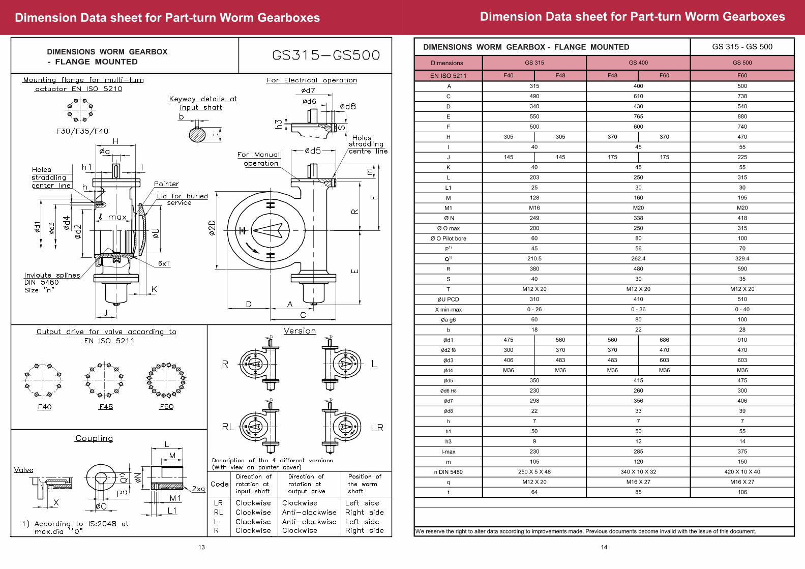
GS 315 - GS 500DIMENSIONS WORM GEARBOX - FLANGE MOUNTED
GS 315 GS 400 GS 500
60 80
418
30
M20
F40 F48 F48 F60 F60
305
Q
R
S
T
ØU PCD
X min-max
Øa g6
b
Ød1
Ød2 f8
Ød3
Ød4
Ød5
Ød6 H8
Ød7
Ød8
h
h1
h3
l-max
m
n DIN 5480
q
t
105
50
260
483
M36 M36
230
M16 X 27
475
300
M16 X 27
406
12
39
14
375
150
285
120
9
350
686
33
64 85 106
380
M12 X 20
30
22
510
0 - 40
420 X 10 X 40
100
7
50
22
230
483
370
28
80
590
0 - 36
40
310 410
35
480
560
370
60
0 - 26
18
M12 X 20 M12 X 20
560
298
415
603
M36
406
M36
356
475
300
M12 X 20
910
470
7 7
250 X 5 X 48 340 X 10 X 32
470
603
M36
55
We reserve the right to alter data according to improvements made. Previous documents become invalid with the issue of this document.
14
DIMENSIONS WORM GEARBOX
- FLANGE MOUNTED
Dimension Data sheet for Part-turn Worm Gearboxes
13

Dimension Data sheet for Part-turn Worm Gearboxes
Dimensions
GZ Ratio (i)
EN ISO 5210
DIN 3210
EN ISO 5211
A
B
C
D
E
G
H
I
J
K
L
M
L1
M1
Ø N
Ø O max
Ø O Pilot bore
1)
GS 500/GZ 40
418
837
315
100
70
786
G½
F48 F60 F48
G3
176
610
338
80
56
250
550
666
160
M20
203
128
305
195
3030
250
M20
880
55
315
400
45
826
430
846
F10
765
666
340
45
F40 F40
G3 G½
225
F14
470
55
540
1090 1070
F60
500
32:116:1
F14
F60
16:1
G½
32:1
F16 F14
F48 F60
370
40
145
GS 400/GZ 35
G0
315
730
8:1
F16
F40
8:1
GS 315/GZ 30
F48F48
16:1
F14
G½
F48
490
725
F14
G½
32:1
40
M16
249
200
60
25
45
GS315 / GZ 30 - GS500 / GZ 40
P1)
Q1)
R1
T
Ø U PCD
V
W
X min - max
Øa g6
c
Ø d1
Ø d2 f8
Ø d3
Ø d4
e
h
h1
l max
n’ DIN 5480
q
F10
-
F14
F16
h3
4
4
340 X 10 X 32 420 X 10 X 40
M16 X 27 M16 X27
285 375
50 65
7 7
470
63
55 65 5565
M36 M36
483 603
M12 X 20
603
370 470
910
63
70
329.4
73
240
30
510
1010
M12 X 20
40
73
0-36 0-40
40 30
295
480
410
590
766
262.4
56
EN ISO 5210
M12 X 20
250 X 5 X 48
45
210.5
666 685
M12 X 20
310
240
480
0-26
30
63
20
43
475 560 475 560 475 560
300 370 300 370 300 370
406 483 406 483 406 483
M36
55 38
7
50
230
560 686 560 686 560 686
125
30
370 470 370 470
483 603 483 603
DIN 3210
-
G0
G½
G3
Øa g6
20
20
100
13040
b
6
6
8
12
Ød5
125
Ød8
11
11
18
22
175
210
Ød6 H8
70
60
z1
40
40
60
80
Ød7
102
102
140
165
22.5
22.5
33
43
5
6
Weight
kg
1
1
2.3
5
Mounting flanges for multi-turn actuator
t
11
lbs
2.2
2.2
5
F16 G3 13040 12 22210 80165 436
For GS 500/ GZ 40 /GZ 16, i.e. reduction ratio 64:1, refer to separate dimension drawing
We reserve the right to alter data according to improvements made. Previous documents become invalid with the issue of this document.
5 11
DIMENSIONS WORM GEARBOX - FLANGE MOUNTED
16
Dimension Data sheet for Part-turn Worm Gearboxes
DIMENSIONS WORM GEARBOX
- FLANGE MOUNTED
15

Technical Data sheet for Part-turn Worm Gearboxes
Output torque for manual operation
Output torque for motor operation
Input torque at max. output torque
Input torque at nominal output
OTums for 90
Weight
Handwheel diameter
Mounting flange for multi-turn actuator
Suitable multi-turn actuator (with output drive)
Max. permissible weight of multi-turn actuator
Operating time in sec. O
for 90 at actuator speedx Operating times shorter than indicated(18-25 sec) only after consultation withfactory
Operator
Reduction
Reduction ratio
Reduction ratio
Total reduction ratio
Nm
Type
GFi =
GZi =
GF+GZi =
Nm
Nm
lbs. ft.
lbs. ft
Type
Nm
54:1 54:1
4:1
216:1
8:1
432:1
54:1 53:1
GZ 14
465
330
243
13.5
343
__ __ __
____ __
138
98
72
54
102
69 940
49 670
36 495
108 13.25
51 694
mm
16 1/min
22 1/min
32 1/min
45 1/min
63 1/min
90 1/min
125 1/min
180 1/min
51
37
25
18
X
X
X
X
204
148
102
72
51
36
25
18
50
36
25
18
X
X
X
X
296
204
144
102
72
51
36
-
inch
kg
lbs.
175
385
25/32
640/800
195
429
16
400
195
429
12
300
320
704
- -
- -
Mechanical advantage 24.2 82 164 23.9
lbs. ft.
lbs. ft.
kg
lbs. 220
100
135
60
135
60 160
350
ISO 5210
DIN 3210 -
F 14
SA 50
G0 G0
F 10
SA 12
F 10
SA 6 SA 6
F 16
SA 100
-
11250
GF 160
8000
8300
5900
22500
GF 200
GZ 16
16000
16600
11800
For rare operation, based on a service life of Omin. 2000 cycles of 90
Nominal torque for frequent operation, based on Oa service life of min 15000 operating cycles of 90
Conversion factor output torque to input torque
1)
2)
3)
Observing the permissible effort at handwheel
Flanges at GF and GZ according to ISO 5210 are standard
The operating times mentioned are approximate for service at
50 Hz, at 60Hz, the speeds increase by 20% and the operating
times reduce to 83% of the stated values
4)
5)
6)
GF 160 - GF 250
1)
1)
2)
3)
4)
5)
6)
8:1 16:1 4:1 16:18:1
424:1 208:1848:1 832:1416:1
53:1 53:1 52:1 52:1 52:1 52:1
106
138
98 50
72
212
102 51 1420
56069 1923
400
37
13
280 140
2001370 100
1010 295 148 74
49
35
24
X
X
X
X
X
196
140
98
70
49
35
24
17
392
280
196
140
98
70
49
35
392
280
196
140
98
70
288
200
144
100
72
50
36
288
200
144
100
72
- -
-
-
-
-
350 350 490
770 770 1078
16
400
525
1155
12 32 20/25
800300
525
1155 1155
16
400500/640
525
163 320 23.4 80 160 320
52 104 208
207 104414
135 135
60 60
660
60
135220 180
100 80300
F 10
SA 12
F 10 F 10F 25
SA 50 SA 25
F 14
-
F 14
SA 12
G0 G0 - G0
45000
GF 250
GZ 25
32000
33200
23600
4:1
212:1
53:1
53
276
196
145
204
200
144
100
72
50
36
25
18
350
770
20/25
500/640
82
180
80
G12 G1
2 G12
F 14
SA 25
2) TN
max
We reserve the right to alter data according to improvements made. Previous documents become invalid with the issue of this document.
TECHNICAL DATA FOR PART-TURN FOR WORM GEARBOXES(FLANGE MOUNTED) AND PRIMARY REDUCTION GEARS
Type of enclosure IP 67 dust proof and water tightIP 68 enclosure on request
Ambient temperature range
GF O O20 C +80 C- -
18
Technical Data sheet for Part-turn Worm Gearboxes
GF 63.2 - GF 125.2
Output torque for manual operation
Output torque for motor operation
Input torque at max. output torque
Input torque at nominal output torque
Mechanical advantage
OTums for 90
Suitable actuator (with output drive type E) Type
Max. permissible weight of actuator
OOperating time in sec. for 90 at actuator speed Operating times shorter than indicated (13-17 sec) only after consultation with
OFor rare operation, based on a service life of min. 2000 cycles of 90
ONominal torque for frequent operation, based on a service life of min 15000 operating cycles of 90
Conversion factor output torque to input torque
Recommendation, based on an usual manual effort for most of the travel and a permissible higher force in order to fully close or break open the valve
The operating times mentioned are approximate for service at 50 Hz, at 60 Hz the speeds increase by 20% and the operating times reduce to 83% of the
1)
2)
3)
4)
5)
Operator
Reduction
Total reduction ratio
Nm
Type
GF(+VZ4) i=
Nm
Nm
lbs. ft.
lbs. ft
Type
Nm
__ __ __ __
850
GF 63.2
39:1
51
36
26
16.7
9.75
38
600
1400
GF 80.2
40:1
81
58
43
17.3
10
60
40:1
162
116
85
17.3
10
120
157:1
48
34
25
58.5
39
35
52:1
250
178
131
22.5
13
184
204:1
74
53
39
kg
lbs.
8
11
16
22
32
45
63
90
73
53
36
27
18
13
75
55
38
27
19
14
75
55
38
27
19
14
98
70
49
35
24
17
296
216
148
108
74
54
37
27
384
274
192
137
96
69
48
35
SA 6 SA 6 SA 6 SA 25 SA 6SA 12
30
66
30
66
30
66
30
66
30
66
70
155
75.5
51
54
1000
2800
GF 100.2
2000
5600
GF 125.2
VZ 4 VZ 4
4000
625
440
1030
750
2060
1500
4120
3000
lbs. ft.
lbs. ft.
Input shaft diametermax. mm
max. inch
20
0.787
20
0.787
20 20
0.787 0.787
2030
0.7871.181
Handwheel diametermm
inch
250/300
10/12
300/350
12/14
350/400 250/300
14/16 12/14
300/350400/500
12/1416/20
Weight (without handwheel)kg
lbs.
19
42
26
57
48
105
54
120
61
128
57
115
Mounting flange for actuatorISO 5210
DIN 3210
F10 F10 F10 F10 F10F14
G0 G0 G0 G0 G0G12
Type of enclosure IP 67 dust proof and water tightIP 68 enclosure on request
Ambient temperature range
GF O O20 C +80 C- -
1)
2)
1)
2)
3)
4)
5)
TN
max.
factory
stated values
We reserve the right to alter data according to improvements made. Previous documents become invalid with the issue of this document.
TECHNICAL DATA FOR PART-TURN WORM GEARBOXES (FOOT MOUNTED) AND PRIMARY REDUCTION GEARS
17
Technical Data sheet for Part-turn Worm Gearboxes
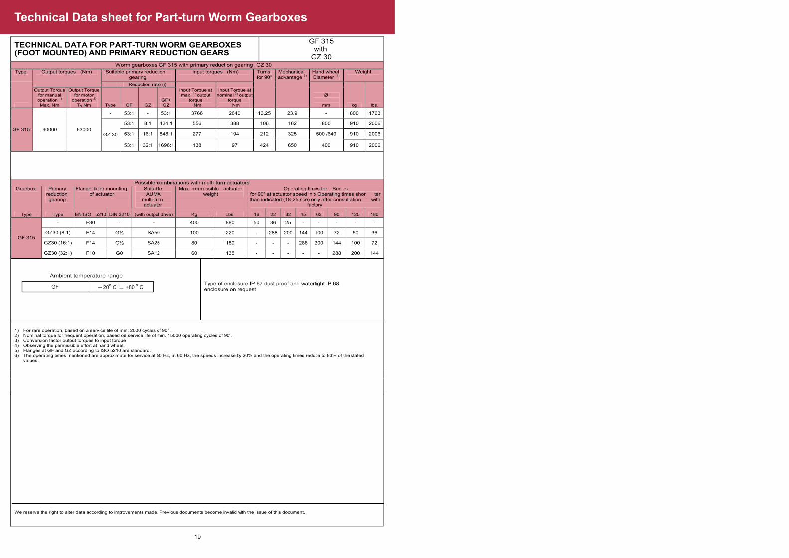
TECHNICAL DATA FOR PART-TURN WORM GEARBOXES(FOOT MOUNTED) AND PRIMARY REDUCTION GEARS
GF 315 with
GZ 30 Worm gearboxes GF 315 with primary reduction gearing GZ 30
Type Output torques (Nm) Suitable primary reduction gearing
Input torques (Nm) Turns
for 90° Mechanical advantage 3)
Hand wheel
Diameter 4) Weight
Reduction ratio (i)
Input Torque at max. 1) output
torque Nm
Input Torque at nominal 2) output
torque Nm
Ø
mm kg lbs.
Output Torque for manual operation 1)
Max. Nm
Output Torque for motor
operation 2)
TN Nm Type GF GZ GF+ GZ
GF 315 90000 63000
- 53:1 - 53:1 3766 2640 13.25 23.9 - 800 1763
GZ 30
53:1 8:1 424:1 556 388 106 162 800 910 2006
53:1 16:1 848:1 277 194 212 325 500 /640 910 2006
53:1 32:1 1696:1 138 97 424 650 400 910 2006
Possible combinations with multi-turn actuators
Gearbox Primary reduction gearing
Flange 5) for mounting of actuator
Suitable AUMA
multi-turn actuator
Max. permissible actuator weight
Operating times for Sec. 6) for 90º at actuator speed in x Operating times shor ter than indicated (18-25 sce) only after consultation with
factory
Type Type EN ISO 5210 DIN 3210 (with output drive) Kg Lbs. 16 22 32 45 63 90 125 180
GF 315
- F30 - - 400 880 50 36 25 - - - - -
GZ30 (8:1) F14 G½ SA50 100 220 - 288 200 144 100 72 50 36
GZ30 (16:1) F14 G½ SA25 80 180 - - - 288 200 144 100 72
GZ30 (32:1) F10 G0 SA12 60 135 - - - - - 288 200 144
Type of enclosure IP 67 dust proof and watertight IP 68 enclosure on request
1) For rare operation, based on a service life of m in . 2000 cycles of 90°. 2) Nominal torque for frequent operation, based ona service life of min. 15000 operating cycles of 90°. 3) Conversion factor output torques to input torqu. e4) Observing the permissible effort at hand wheel. 5) Flanges at GF and GZ according to ISO 5210 are st a ndard. 6) The operating times mentioned are approximate for service at 50 Hz, at 60 Hz, the speeds increase by 20% and the operating times reduce to 83% of the stated
values.
We reserve the right to alter data according to improvements made. Previous documents become invalid with the issue of this document.
Ambient temperature range
GF O O20 C +80 C- -
19
Dimension Data sheet for Part-turn Worm Gearboxes
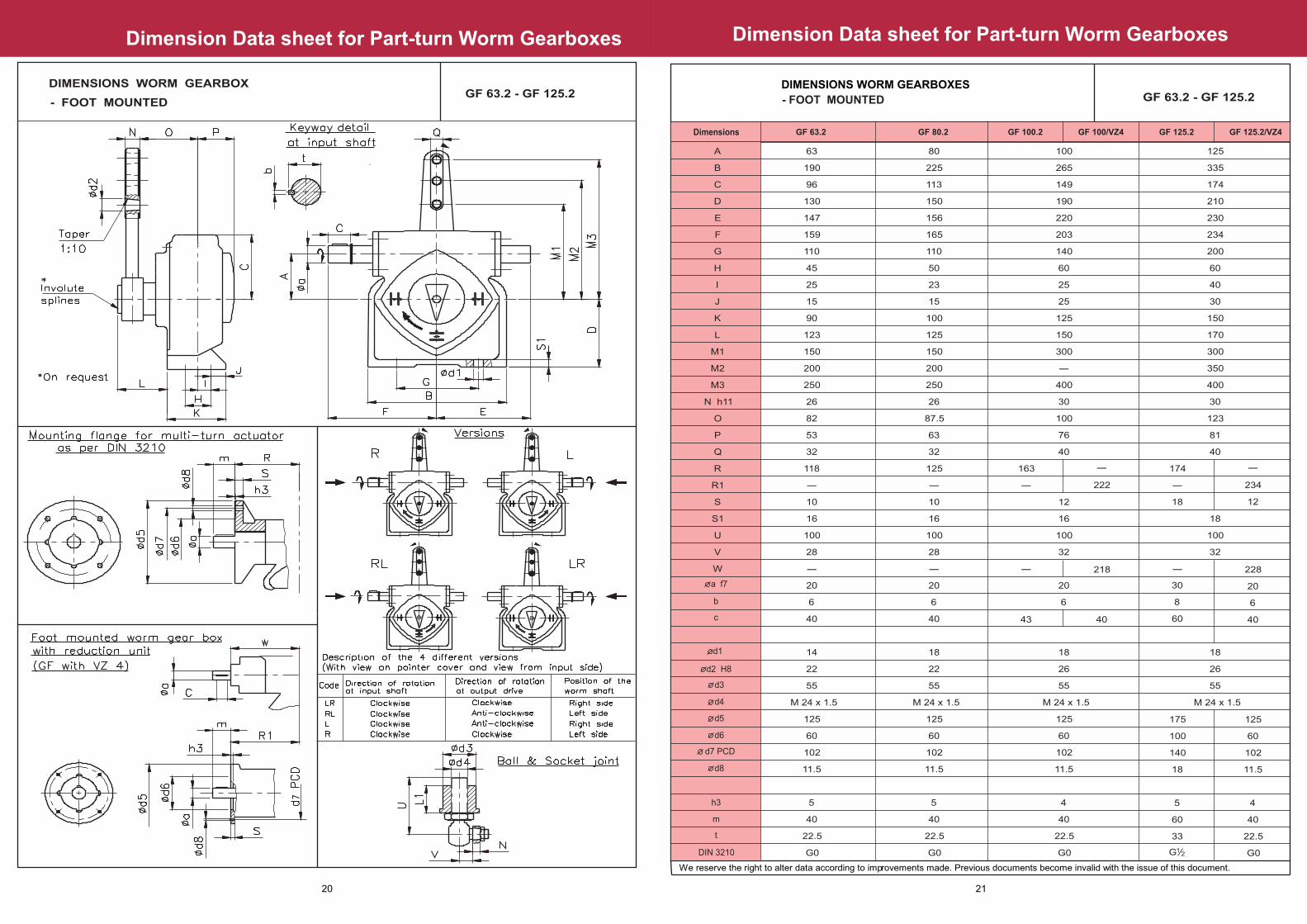
GF 63.2 - GF 125.2
GF 63.2 GF 80.2 GF 100.2 GF 100/VZ4 GF 125.2 GF 125.2/VZ4Dimensions
A
B
C
D
E
F
G
H
I
J
K
L
M1
M2
M3
N h11
O
P
Q
R
R1
S
S1
U
V
W
63
190
96
130
147
159
110
45
25
15
90
123
150
200
250
26
82
53
32
118
10
16
100
28
20
6
40
14
22
55
M 24 x 1.5
125
60
102
11.5
5
40
22.5
G0
80
225
113
150
156
165
110
50
23
15
100
125
150
200
250
26
87.5
63
32
125
10
16
100
28
20
6
40
18
22
55
M 24 x 1.5
125
60
102
11.5
5
40
22.5
G0
100
265
149
190
220
203
140
60
25
25
125
150
300
400
30
100
76
40
12
16
100
32
20
6
18
26
55
M 24 x 1.5
125
60
102
11.5
4
40
22.5
G0
- - --
- - - -
- -
-
163 174
18
30
8
60
175
100
140
18
5
60
33
125
60
102
11.5
4
40
22.5
G0
228
20
6
4043
222 234
12
218
40
125
335
174
210
230
234
200
60
40
30
150
170
300
350
400
30
123
81
40
18
100
32
18
26
55
M 24 x 1.5
G12
b
c
a f7
d2 H8
d3
d4
d5
d6
d8
d7 PCD
d1
h3
m
t
DIN 3210
We reserve the right to alter data according to improvements made. Previous documents become invalid with the issue of this document.
DIMENSIONS WORM GEARBOXES
- FOOT MOUNTED
21
Dimension Data sheet for Part-turn Worm Gearboxes
DIMENSIONS WORM GEARBOX
- FOOT MOUNTEDGF 63.2 - GF 125.2
20

Dimension Data sheet for Part-turn Worm Gearboxes
GF 160 GF 160 / GZ 14 GF 200 / GZ 16 GF 250 / GZ 25GF 200 GF 250Dimensions
4:1
160
410
250
300
340
220
120
114
60
250
202
400
500
30
143
90
20
100
32
26
26
55
M 24 x 1.5
A
B
C
D
E
F
G
H
I
J
K
L
M1
M2
O
P
R
S
S1
U
V
c
200
500
305
375
400
360
180
141
50
300
278
500
600
40
198
110
30
130
43
33
38.5
65
M 24 x 1.5
250
630
400
380
490
400
125
90
45
260
257
600
800
42
211
132
17
30
130
43
60
33
38
65
M 24 x 1.5
8:1 4:1 8:1 16:1 8:1 16:14:1
260 340 420
210
10
274
14
336
16
485 567
12 12
53 105 4379 60
17
4343
405
12
- - -
Mounting dimensions for multi-turn actuator
WeightISO 5210 DIN 3210
F 10
F 14
F 16
F 25
G0
G3
G4
-
-
-
-
G12
20
20
30
40
50
50
6
6
8
12
14
14
125
125
175
210
300
300
70
60
100
130
200
160
102
102
140
165
254
254
11
11
18
22
18
18
4
4
5
6
6
6
40
40
50
80
100
100
22.5
22.5
33
43
53.5
53.5
1
1
2.3
5
11
11
2.2
2.2
5
11
24
24
a g6 b d5 d6 d7 d8 h3 m tkg lbs
i (GZ)
N h11
d1
d3
d4
d2 H8
GF 160 - GF 250
We reserve the right to alter data according to improvements made. Previous documents become invalid with the issue of this document.
DIMENSIONS WORM GEARBOXES - FOOT MOUNTED
23
Dimension Datasheet for Part-turn Worm Gearboxes
GF 160 - GF 250DIMENSIONS WORM GEARBOXES
- FOOT MOUNTED
22
Technical Data sheet for Multi-turn Worm Gearboxes
GS 40.2 - GS 125.2
Output torque for manual operation
Output torque for motor operation
Input torque at max. output torque
Input torque at nominal output torque
Mechanical advantage
OTums for 90
Suitable multi-turn actuator (with output drive type E)
Max. permissible weight of multi-turn actuator
OOperating time in sec. for 90 at actuator speed Operating times shorter than indicated (13-17 sec) only after consultation with
OFor rare operation, based on a service life of min. 2000 cycles of 90
O
Nominal torque for frequent operation, based on a service life of
min 15000 operating cycles of 90
Conversion factor output torque to input torque
1)
2)
3)
Operator
Reduction
Total reduction ratio
Nm
Type
GS(+VZ4) i=
Nm
Nm
lbs. ft.
lbs. ft
Type
Nm
__ __ __ __
850
GS 63.2
39:1
51
36
26
16.7
9.75
38
600
1400
GS 80.2
40:1
81
58
43
17.3
10
60
40:1
162
116
85
17.3
10
120
157:1
48
34
25
58.5
39
35
52:1
250
178
131
22.5
13
184
204:1
74
53
39
kg
lbs.
8
11
16
22
32
45
63
90
73
53
36
27
18
13
75
55
38
27
19
14
75
55
38
27
19
14
98
70
49
35
24
17
296
216
148
108
74
54
37
27
384
274
192
137
96
69
48
35
SA 6 SA 6 SA 6 SA 25 SA 6SA 12
30
66
30
66
30
66
30
66
30
66
70
155
75.5
51
54
1000
2800
GS 100.2
2000
5600
GS 125.2
VZ 4 VZ 4
4000
625
440
1030
750
2060
1500
4120
3000
lbs. ft.
lbs. ft.
Input shaft diametermax. mm
max. inch
20
0.787
20
0.787
20 20
0.787 0.787
2030
0.7871.181
Handwheel diametermm
inch
250/300
10/12
300/350
12/16
350/400 250/300
12/16 10/12
300/350400/500
12/1616/20
Weight (without handwheel)kg
lbs.
9
20
13.5
30
30
66
34
75
47
104
43
95
Mounting flange for actuatorISO 5210
DIN 3210
F10 F10 F10F14
G0 G0 G0 G0 G0G12
1)
2)
1)
2)
3)
5)
7)
TN
max.
factory
We reserve the right to alter data according to improvements made. Previous documents become invalid with the issue of this document.
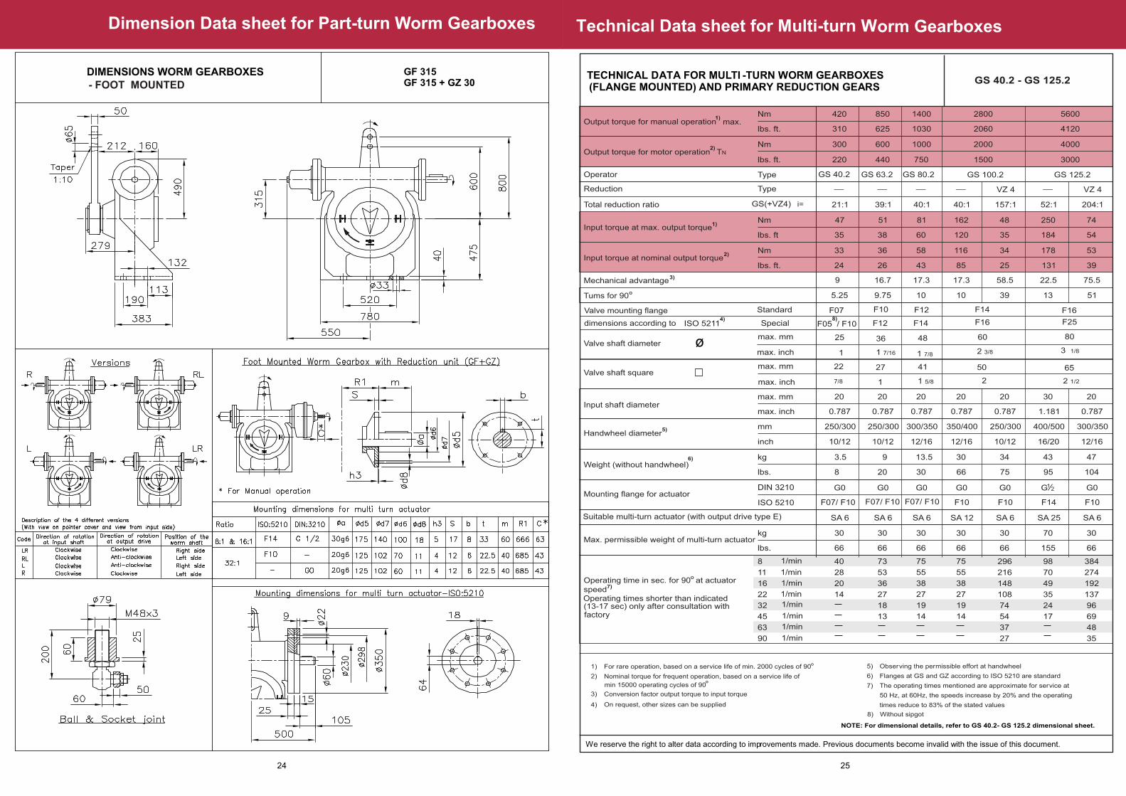
TECHNICAL DATA FOR MULTI -TURN WORM GEARBOXES (FLANGE MOUNTED) AND PRIMARY REDUCTION GEARS
4) On request, other sizes can be supplied
Observing the permissible effort at handwheel
Flanges at GS and GZ according to ISO 5210 are standard
The operating times mentioned are approximate for service at
50 Hz, at 60Hz, the speeds increase by 20% and the operating
times reduce to 83% of the stated values
5)
6)
7)
NOTE: For dimensional details, refer to GS 40.2- GS 125.2 dimensional sheet.
8) Without sipgot
__
420
GS 40.2
21:1
47
33
24
9
5.25
35
300
40
28
20
14
SA 6
30
66
310
220
20
0.787
250/300
10/12
3.5
8
F07/ F10
G0
F07/ F10F07/ F10
1/min
1/min
1/min
1/min
1/min
1/min
1/min
1/min
Valve mounting flange
ISO 52114)
Valve shaft diameter
Standard
25
1
F07
3 1/8
Valve shaft squaremax. mm
max. inch
22
7/8 2 1/2
Special
max. mm
max. inch
dimensions according to
6)
F05 / F108)
F16F14F12F10
F12 F14 F16 F25
4127
1 7/16
80604836
1 5/81
1 7/8 2 3/8
6550
2
ø
25
Dimension Data sheet for Part-turn Worm Gearboxes
DIMENSIONS WORM GEARBOXES GF 315GF 315 + GZ 30 - FOOT MOUNTED
24
Technical Data sheet for Multi-turn Worm Gearboxes
Output torque for manual operation
Output torque for motor operation
Input torque at max. output torque
Input torque at nominal output
OTurns for 90
Weight
Handwheel diameter
Mounting flange for multi-turn actuator
Suitable multi-turn actuator (with output drive type E)
Max. permissible weight of multi-turn actuator
Operating time in sec. O
for 90 at actuator speed
X - Operating times shorter than indicated(18-25 sec) only af ter consultation withfactory
Operator
Reduction
Reduction ratio
Reduction ratio
Total reduction ratio
Nm
Type
GSi =
GZi =
GS+GZi =
Nm
Nm
lbs. ft.
lbs. ft
Type
Nm
53:1 53:1
16:1
848:1
32:1
1696:1
53:1 54:1
GZ 30
556
338
286
13.25
410
__ __
____
278
194
143
212
205
139 7410
97 5140
72 3790
424 13.5
103 5473
mm
16 1/min
22 1/min
32 1/min
45 1/min
63 1/min
90 1/min
125 1/min
180 1/min
288
200
144
100
7250
36
200
144
100
72
51
37
25
X
X
X
X
288
200
144
-
inch
kg
lbs.
630
25/32
640/800
16
400
1386
12
300
980
2156
- -
- -
Mechanical advantage 23.9 325 650 24.3
lbs. ft.
lbs. ft.
kg
lbs. 220
100
135
60
135
60 800
1760
ISO 5210
DIN 3210 -
F 14
SA 50
G0
F 10
SA 12
F 10
SA 6 SA 25
F 35
-
90000
GS 315
63000
66400
46500
180000
GS 400
GZ 35
125000
132800
92200
For rare operation, based on a service life of O
min. 2000 cycles of 90
Nominal torque for frequent operation, based on a service life of O
min 15000 operating cycles of 90
Conversion factor output torque to input torque
1)
2)
3)
Observing the permissible effort at handwheel
Flanges at GS and GZ according to ISO 5210 are standard
The operating times mentioned are approximate for service at
50 Hz, at 60Hz, the speeds increase by 20% and the operating
times reduce to 83% of the stated values
6)
7)
8)
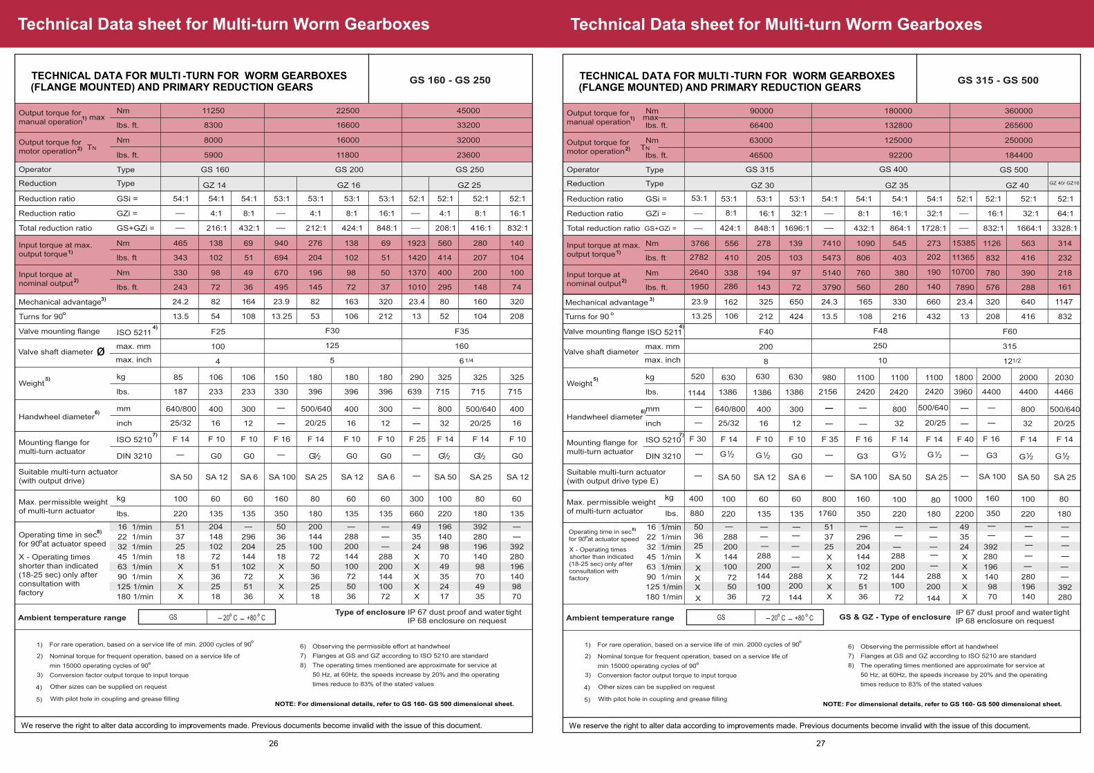
GS 315 - GS 500
1)
1)
2)
3)
6)
7)
8)
16:1 32:1 16:1 64:132:1
864:1 832:11728:1 3328:11664:1
54:1 54:1 52:1 52:1 52:1 52:1
216
545
380 190
280
432
403 202 11365
1126273 15385
780
140
13
563 314
39010700 218
7890 576 288 161
49
35
24
X
X
X
X
X
392
280
196
140
98
70
280
196
140392
280
288
200144
100
72
200
144
- -
-
-
-
-
1100 1100 1800
3960
32
800
2000
4400
32 20/25
800
2000
4400 4466
500/640
2030
330 660 23.4 320 640 1147
208 416 832
416 232832
220 180
100
2200
80
220 180
100 801000
F 14
SA 50
F 14 F 40
SA 50 SA 25
F 14
-
F 14
-
360000
GS 500
GZ 40
250000
265600
184400
8:1
432:1
54:1
108
1090
760
560
806
296
204
144
102
72
51
36
1100
2420
20/25
500/640
165
350
160
G3 G12 G1
2
F 16
SA 100
2) TN
max
We reserve the right to alter data according to improvements made. Previous documents become invalid with the issue of this document.
TECHNICAL DATA FOR MULTI -TURN FOR WORM GEARBOXES(FLANGE MOUNTED) AND PRIMARY REDUCTION GEARS
IP 67 dust proof and water tightIP 68 enclosure on requestAmbient temperature range GS O O
20 C +80 C- -
4) Other sizes can be supplied on request
5) With pilot hole in coupling and grease fillingNOTE: For dimensional details, refer to GS 160- GS 500 dimensional sheet.
5)
Valve mounting flange ISO 52114)
Valve shaft diametermax. mm
max. inch
F40
200
8
F48
250
10
F60
315
12 1/2
GS & GZ - Type of enclosure
GZ 40/ GZ16
-
-
-
---
-
-
---
-
-
F 16
G3
SA 100
160
350
24202420
G12 G1
2
288
-
-
-
-
-
X
-
-
-
53:1
__
__ 424:1
8:1
162
106
3766
1950
2640
2782
630630520
138613861144
-
-
-
F 30
-
400
880
G12G1
2
X
X
XX
X
-
-
-
-
288
-
-
-50
25
36
-
27
Technical Data sheet for Multi-turn Worm Gearboxes
Output torque for manual operation
Output torque for motor operation
Input torque at max. output torque
Input torque at nominal output
OTurns for 90
Weight
Handwheel diameter
Mounting flange for multi-turn actuator
Suitable multi-turn actuator (with output drive)
Max. permissible weight of multi-turn actuator
Operating time in sec. O
for 90 at actuator speed
X - Operating times shorter than indicated(18-25 sec) only after consultation withfactory
Operator
Reduction
Reduction ratio
Reduction ratio
Total reduction ratio
Nm
Type
GSi =
GZi =
GS+GZi =
Nm
Nm
lbs. ft.
lbs. ft
Type
Nm
54:1 54:1
4:1
216:1
8:1
432:1
54:1 53:1
GZ 14
465
330
243
13.5
343
__ __ __
____ __
138
98
72
54
102
69 940
49 670
36 495
108 13.25
51 694
mm
16 1/min
22 1/min
32 1/min
45 1/min
63 1/min
90 1/min
125 1/min
180 1/min
51
37
25
18
X
X
X
X
204
148
102
72
51
36
25
18
50
36
25
18
X
X
X
X
296
204
144
102
72
51
36
-
inch
kg
lbs.
85
187
25/32
640/800
106
233
16
400
106
233
12
300
150
330
- -
- -
Mechanical advantage 24.2 82 164 23.9
lbs. ft.
lbs. ft.
kg
lbs. 220
100
135
60
135
60 160
350
ISO 5210
DIN 3210 -
F 14
SA 50
G0 G0
F 10
SA 12
F 10
SA 6 SA 6
F 16
SA 100
-
11250
GS 160
8000
8300
5900
22500
GS 200
GZ 16
16000
16600
11800
For rare operation, based on a service life of O
min. 2000 cycles of 90
Nominal torque for frequent operation, based on a service life of O
min 15000 operating cycles of 90
Conversion factor output torque to input torque
1)
2)
3)
Observing the permissible effort at handwheel
Flanges at GS and GZ according to ISO 5210 are standard
The operating times mentioned are approximate for service at
50 Hz, at 60Hz, the speeds increase by 20% and the operating
times reduce to 83% of the stated values
6)
7)
8)
GS 160 - GS 250
1)
1)
2)
3)
6)
7)
8)
8:1 16:1 4:1 16:18:1
424:1 208:1848:1 832:1416:1
53:1 53:1 52:1 52:1 52:1 52:1
106
138
98 50
72
212
102 51 1420
56069 1923
400
37
13
280 140
2001370 100
1010 295 148 74
49
35
24
X
X
X
X
X
196
140
98
70
49
35
24
17
392
280
196
140
98
70
49
35
392
280
196
140
98
70
288
200
144
100
72
50
36
288
200
144
100
72
- -
-
-
-
-
180 180 290
396 396 639
16
400
325
715
12 32 20/25
800300
325
715 715
16
400500/640
325
163 320 23.4 80 160 320
52 104 208
207 104414
135 135
60 60
660
60
135220 180
100 80300
F 10
SA 12
F 10 F 10F 25
SA 50 SA 25
F 14
-
F 14
SA 12
G0 G0 - G0
45000
GS 250
GZ 25
32000
33200
23600
4:1
212:1
53:1
53
276
196
145
204
200
144
100
72
50
36
25
18
180
396
20/25
500/640
82
180
80
G12 G1
2 G12
F 14
SA 25
2) TN
max
We reserve the right to alter data according to improvements made. Previous documents become invalid with the issue of this document.
TECHNICAL DATA FOR MULTI -TURN FOR WORM GEARBOXES(FLANGE MOUNTED) AND PRIMARY REDUCTION GEARS
Type of enclosure IP 67 dust proof and water tightIP 68 enclosure on requestAmbient temperature range GS O O
20 C +80 C- -
4) Other sizes can be supplied on request
5) With pilot hole in coupling and grease fillingNOTE: For dimensional details, refer to GS 160- GS 500 dimensional sheet.
5)
Valve mounting flange ISO 52114)
Valve shaft diametermax. mm
max. inch
F25
100
4
F30
125
5
F35
160
6 1/4
ø
26

OUTPUT DRIVE TYPEACCORDING TO DIN 3210
Output Drives
GK 10.1 GK 35.1-
DIN 3210
F max k N
b1 JS9
b2 H11
b3 h9
b4 JS 9
g2
h1
L 6
t 3
g2
L 4L 5
t 2
weight
weight
kg
lbs
kg
lbs
g
h1
h2
L 1
L 2
z
d1
d4
d4
d8 g6
d9 max
DIN 3210
d5
DIN 3210
d9 (H8)
d5 max
d7g1
h1
h3
d3d4
k
d5-max
d5 max
d6 H8g1
h1
L 3
t 1
d2 f8
60
125
60
M10
40
38
37
3
15
102
1
37
4
12
40
38
42
50
2
45
45.3
14
40
20
55
24
70
30
90
40
110
45
125
28 38 47 64 75 105
38
50
50
3
10
6
20
15
50
55
22.5
32
15
3
55
22.8
45
22
4
77
33.3
60
30
4
97
43.3
80
35
4
130
53.8
80
35
5
130
64.4
110
40
5
130
85.4
8
30
22
70
76
33
12
40
30
90
96
43
14
50
35
110
116
53.5
18
60
35
120
127
64
22
80
40
120
127
85
52
75
65
4
12
65
100
80
4
15
86
130
110
4
16
86
150
130
5
18
121
205
180
5
22
18
55
52
60
65
2
65
64.4
22
70
65
80
80
2
80
85.4
28
90
86
100
110
2
110
106.4
32
110
105
120
130
3
130
127.4
40
125
121
160
180
3
180
169.4
2
4.4
2
4.4
6
13
6
13
12
26
12
26
32
70
32
70
40
88
40
88
85
187
85
187
weightkg
lbs
2
4.4
6
13
12
26
32
70
40
88
85
187
20 30 40 50 60 80
6 8 12 14 18 22
weightkg
lbs
1.5
3.3
3.5
7.7
6
13
15
33
17
37
30
66
weightkg
lbs
1.5
3.3
3.5
7.7
6
13
15
33
17
37
30
66
160
175
100
M16
55
52
51
4
22
140
2
51
4
190
210
130
M20
70
65
69
4
30
165
2
70
4
320
300
160
M16
90
86
90
4
25*
254
2
85
8
450
350
180
M20
110
105
152
5
25*
300
2
150
8
820
410
220
M30
125
121
150
5
30*
356
2
146
8
G0
GK 10.1 GK 14.1
Bevel Gearbox Type
GK 16.1 GK 25.1 GK 30.1 GK 35.1Dimensions
G3 G4 G5 G6G1/2
We reserve the right to alter data according to improvements made. Previous documents become invalid with the issue of this document.
Output Drive Details for Multi-turn Bevel Gearboxes
29
Technical Data sheet for Multi-turn Bevel Gearboxes
BEVEL GEARBOX TECHNICAL DATA /
DIMENSIONS
Dimensions of flange and input shaftt
GK 10.1 - GK 35.1
Nmlbsft
MaxOutputtorque
120
90
132
10040
88
1:1 0.9
2:1 1.8
G0
(F10)
60
13500
6
13 250/35010/14
SA6
350/40014/16
SA12/SA15
16036000
1124
350/40014/16
SA12/SA15
4088
70155
90200
90200
150330
19042700
2248
400/64016/25
SA25/SA30
SA50/SA60
SA50320
7200053117
500/64020/25
450101500
74163
640/80025/32
820185000
123271
80032
GK 10.1 G0
GK 14.1
GK 16.1
GK 25.1
GK 30.1
GK 35.1
G3(F16)
G4(F25)
G5(F30)
G6(F35)
4:1 3.6
4:1 3.5
6:1 5.4
8:1 7.2
8:1 7.2
120
90
67
50500
375
140
105
52
21000
750
280
2102000
1500
370
2704000
3000
560
410
102
48000
6000
1)
2)
3)
At max output torque
Conversion factor output torque : input torque
The permissible axial forces are considerably beyond the max. thrust of actuators
available when converting rotary to linear movement by using trapezoidal thread
4)
5)
6)
Gearbox without drive adapter and without mounting flange for actuator
Observing the permissible effort at hand wheel
Depending on required gearbox output torque
1100
810
Reduction
ratio
Nmlbsft
1) 2) 3) 5)
SA1006)
Inputtorque
Mech.advantage
Gearbox
TypeDIN 3210
(ISO 5210)
Outputdrive
Kglbs
4)
Weight
mminch
Hand wheeldiameter
DIN 3210
Actuatormounting
flange
aumatype
Suitableactuator
max.Kgmax.lbs
Weightof actuator
Stemdiameter
for Type A
max.mmmax.inch
Thrustpermissiblefor Type A
max.kNmax.lbs
(F14)
G12
G12
G12
(G )12
G12
G3
38
1 12
65
2 12
86
3 38
121
4 34
G0
G3
125
175
210
12
17
25
6
8
12
20g6
30g6
40g6
11
18
22
102
140
165
60
100
130
4
5
6
40
60
80
22.5
33
43
1
2.3
5
2.2
5
11
DDIN 3210Actuatormounting
flange
b5R d d10 d11 d12 h3 t 4 kg lbsI
G12
Dimensions
130
180
230
340
370
450
65
90
115
170
185
225
160
160
193
230
244
283
69
76
103
129
138
165
105
130
164
236
256
303
110
135
169
241
262
309
134
137
166
200
215
253
125
175
210
300
350
410
37
51
69
90
152
150
50
65
80
110
130
180
15
22
30
35
35
40
M12
M16
M20
150
175
389
195
229
301
322
-
-
-
-
- -
-
-
-
-
-
-
-
-
60 x 3.7
76 x 3.7
89 x 4.1
114 x 4.5
114 x 4.5
140 x 4.9
G 2''
G3''
G4''
G4''
G5''
D2 D3A
GK 10.1
GK 14.1
GK 16.1
GK 25.1
GK 30.1
GK 35.1
B C E G M Y g g1 g2O d1G 0 G 3
L
G 1 2
12G 2 ''
STANDARD BEVEL GEARBOX
* Type of Enclosure IP67 dust proof & watertight. IP68 enclosure on request
We reserve the right to alter data according to improvements made. Previous documents become invalid with the issue of this document.
G0
28

BEVEL GEARBOX DIMENSIONAL DATA GK 40.1
We reserve the right to alter data according to improvements made. Previous data sheets become invalid with the issue of this data sheet.
Dimensional Data sheet for Multi-turn Bevel Gearboxes
31
Technical Data sheet for Multi-turn Bevel Gearboxes
BEVEL GEARBOX TECHNICAL DATA GK 40.1
Type
Output torque
Thrust permissible for type A
max kN
Reduction ratio
Input torque1) Valve attachment
Factor 2) Input shaft Ø
Hand- Wheel
Weight 3)
Nominal torque max. Nm
Nominal torque
Nm
Standard
ISO 5210
Option
DIN 3210 Standard Option
max Ø mm
approx. kg
GK 40.1 16000 1375 16:1 1111
F40 G74) 14.4
40 - 800 250 22:1 808 19.8
Possible combinations with multi-turn actuators
Gearbox
Type
Mounting flange for actuator
Permissible actuator weight
max. kg
Suitable Auma
Multi-turn actuator5)
Type
Standard ISO 5210
Option DIN 3210
GK 40.1 F16/F25
G3/G4 107/300 SA100/SA25.1
F16 G3 107 SA100
Application
Manual operation and motor operation of valves (e.g. gate valves and globe valves)
Features and functions
Type of duty Short-time duty S2-15 min. (open-close duty)
Direction of rotation Standard: Clockwise rotation at input shaft results in clockwise rotation at output shaft Option: Alternative direction of rotation counterclockwise possible
Stages Double stage
Input shaft Cylindrical with parallel key according to IS 2048
Operation
Motor operation With electric multi-turn actuator, directly Flanges for mounting of multi-turn actuator
Manual operation Standard: Via hand wheel, directly
Valve attachment
Output drive forms A type according to ISO 5210 (Other types of output drives shall be offered on request)
Service conditions
Enclosure protection according to IS/IEC 60529
Standard: IP 67
Corrosion protection Standard: Suitable for installation in industrial units, In water or power plants with a low pollutant concentration
Paint Standard: Epoxy primer + Epoxy finish paint Option: Other paints on request
Colour Standard: D.A. Grey Code 632 as per IS: 5 Option: Other colours on request
Ambient temperature Standard: - 20 °C to + 80 °C Option: Others temperature requirements on request
Other information
Reference documents Product description Bevel Gearbox GK 40.1 Dimension sheet GK 40.1 Technical data SA
1) At max. Output torque 2) Conversion factor output torque to input torque to determine the actuator size 3) Gearbox without output shaft and without mounting flange for actuator 4) Without spigot 5) Standard flange according to ISO 5210
We reserve the right to alter data according to improvements made. Previous data sheets become invalid with the issue of this data sheet.
Option: IP 68
30

BEVEL GEARBOX ABG10.2 – ABG35.2
Features and functions
Type of duty Short time duty S2-15 min ( OPEN -CLOSE Duty)
Direction of rotation
Clockwise rotation at input shaft results in clockwise rotation at output drives
Input shaft Cylindrical with parallel key according to IS 2048
Operation
Motor operation
With electric multi-turn actuator
Flanges for mounting of multi-turn actuator as per standard ENISO5210/DIN3210
Manual operation
Via hand wheel
Available hand wheel diameters, selection according to the max. output torque
Type ABG10.2 ABG14.2 ABG16.2 ABG25.2 ABG30.2 ABG35.2
Hand wheel dia mm
250/350 350/400 400/640 500/640 640/800 800
Valve attachment
Valve attachment
Dimensions according to EN ISO 5210
Service conditions
Mounting position
Any position
Enclosure protection according to IS/IEC 60529
Standard IP67 - Dust proof & water tight
Option IP68 - Enclosure can be provided on request
Corrosion protection
Standard Suitable for installation in industrial units, in water or power plants with a low pollutant concentration
Option Others on request
Paint Standard Powder coating as primer + Epoxy finish paint
Option Other paints on request
Colour Standard Smoke grey Code 692 as per IS:5
Option Other coloures on request
Ambient Temperature
Standard –20 ºC to +80 ºC
Option Other temperature requirements on request.
We reserve the right to alter data according to improvements made. DD/CT.018 ISSUE 08/16
Technical Data sheet for Multi-turn Bevel Gearboxes
33 32
Technical Data sheet for Multi-turn Bevel Gearboxes
BEVEL GEARBOX ABG10.2-ABG35.2
Technical data/Dimension
Gearbox Type
ABG10.2 ABG14.2 ABG16.2 ABG25.2 ABG30.2 ABG35.2
Max. Output torque Nm 375 750 1500 2500 5000 8000
Reduction ratio 3:1 4:1 4:1 6:1 8:1 8:1
Input torque1)Nm 139 208 417 463 694 1111
Mech. advantage2) 2.7 3.6 3.6 5.4 7.2 7.2
Stem dia Max.mm 40 50 60 74 100 110
Thrust Permissible for A typekN
80 160 200 320 450 820
Input shaft dia mm 20 30 30 30 30 40
Output drive - Type A type
Weight3) kg 12 20 35 62 95 143
Hand wheel dia4)mm 250/350 350/400 400/640 500/640 640/800 800
Valve attachment
ENISO 5210
F14 F16/F14* F25/F16* F30/F25* F35/F30* F35
DIN 3210
G½ G3/G½* G4/G3* G5/G4* G6/G5* G6
Combination with actuator
Actuator mounting flange
ENISO 5210
F10 F14 F14 F14 F14/F16 F16
DIN3210
G0 G½ G½ G½ G½/G3 G3
Suitable actuator SA15 SA25 SA50 SA50/ SA60 SA606) /SA100 SA100
Weight of actuator kg
33 71 99 99 99/131 131
1. At max.output torque
2. Conversion factor Output torque: Input Torque
3. Gear box without hand wheel andactuator mount ing f lange
4. Observing the permissible ef fort at hand wheel
5. Depending on required gearbox output torque
*Option- Can be provided on request
*For Special Torque, Thrust & Stem DIA Acceptance, Please Contact AUMA India
We reserve the right to alter data according to improvements made. DD/CT.018 ISSUE 08/16

35
Dimensional Data sheet for Multi-turn Bevel Gearboxes
DIMENSIONAL DATA FOR MULTI -TURN BEVEL GEARBOXES
DIN3210 FD1 FD2 FD3 FD4 R h3
G0 125 102 60 11 12 4
G 1/2 175 140 100 18 17 5
G3 210 165 130 22 25 6
Actuator
Mounting
f lange
BEVEL GEARBOX
Dimension
Dimensional Data sheet for Multi-turn Bevel Gearboxes
ABG 10.2 - ABG 35.2
34

36
Dimensional Data sheet for Multi-turn Bevel Gearboxes
ABG 10.2 - ABG 35.2


