29
A A u u t t o o C C A A D D Engr. Ali Haider Swedish College of Engineering & Technology, Wah Cantt Lecture # 3
| Date post: | 01-Jan-2016 |
| Category: |
Documents |
| Upload: | marsha-sharp |
| View: | 226 times |
| Download: | 6 times |
AAuuttoo CCAADD
Engr. Ali Haider
Swedish College of Engineering & Technology, Wah Cantt
Lecture # 3
2
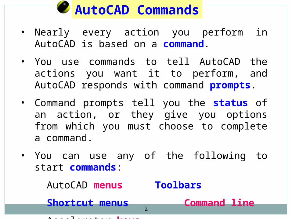
AutoCAD Commands
• Nearly every action you perform in AutoCAD is based on a command.
• You use commands to tell AutoCAD the actions you want it to perform, and AutoCAD responds with command prompts.
• Command prompts tell you the status of an action, or they give you options from which you must choose to complete a command.
• You can use any of the following to start commands:
AutoCAD menus Toolbars
Shortcut menus Command line
Accelerator keys
3
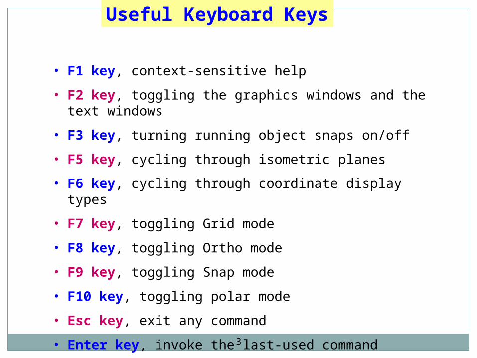
• F1 key, context-sensitive help
• F2 key, toggling the graphics windows and the text windows
• F3 key, turning running object snaps on/off
• F5 key, cycling through isometric planes
• F6 key, cycling through coordinate display types
• F7 key, toggling Grid mode
• F8 key, toggling Ortho mode
• F9 key, toggling Snap mode
• F10 key, toggling polar mode
• Esc key, exit any command
• Enter key, invoke the last-used command
Useful Keyboard Keys
4
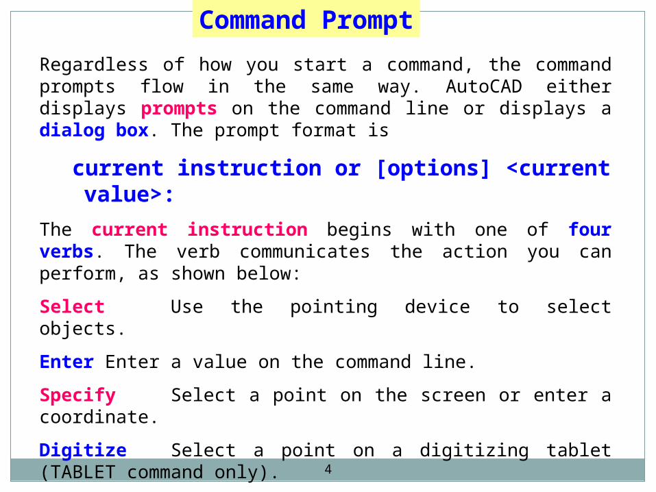
Command Prompt
Regardless of how you start a command, the command prompts flow in the same way. AutoCAD either displays prompts on the command line or displays a dialog box. The prompt format is
current instruction or [options] <current value>:
The current instruction begins with one of four verbs. The verb communicates the action you can perform, as shown below:
Select Use the pointing device to select objects.
Enter Enter a value on the command line.
Specify Select a point on the screen or enter a coordinate.
Digitize Select a point on a digitizing tablet (TABLET command only).
Commands often have options, which are displayed within brackets.
5
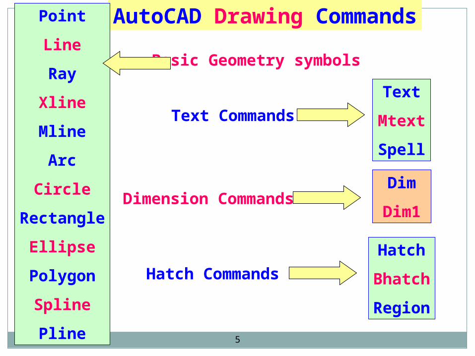
AutoCAD Drawing CommandsPoint
Line
Ray
Xline
Mline
Arc
Circle
Rectangle
Ellipse
Polygon
Spline
Pline
Basic Geometry symbols
Text
Mtext
Spell
Dim
Dim1
Hatch
Bhatch
Region
Text Commands
Dimension Commands
Hatch Commands
6
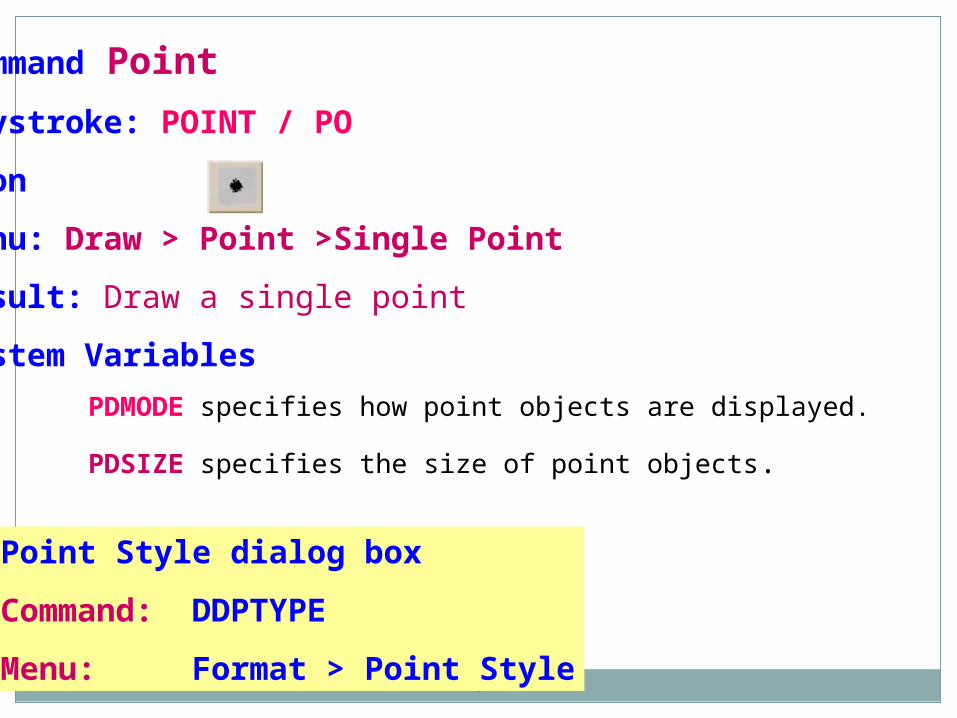
Command Point
Keystroke: POINT / PO
Icon
Menu: Draw > Point >Single Point
Result: Draw a single point
System Variables
PDMODE specifies how point objects are displayed.
PDSIZE specifies the size of point objects.
Point Style dialog box
Command: DDPTYPE
Menu: Format > Point Style
7
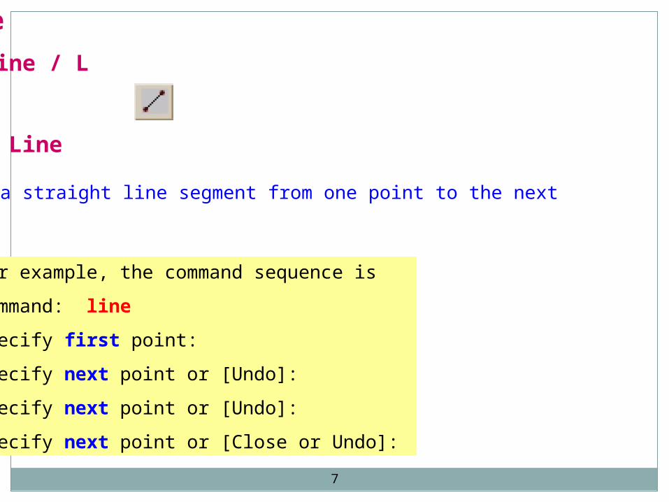
Command Line
Keystroke: Line / L
Icon
Menu: Draw > Line
Result: Draw a straight line segment from one point to the next
For example, the command sequence is
Command: line
Specify first point:
Specify next point or [Undo]:
Specify next point or [Undo]:
Specify next point or [Close or Undo]:
8
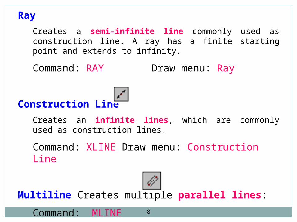
Ray
Creates a semi-infinite line commonly used as construction line. A ray has a finite starting point and extends to infinity.
Command: RAY Draw menu: Ray
Construction Line
Creates an infinite lines, which are commonly used as construction lines.
Command: XLINE Draw menu: Construction Line
Multiline Creates multiple parallel lines:
Command: MLINE
Draw menu: Multiline
9
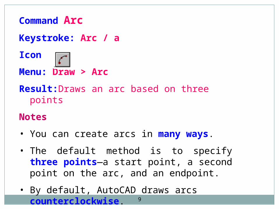
Command Arc
Keystroke: Arc / a
Icon
Menu: Draw > Arc
Result:Draws an arc based on three points
Notes
• You can create arcs in many ways.
• The default method is to specify three points—a start point, a second point on the arc, and an endpoint.
• By default, AutoCAD draws arcs counterclockwise.

10
Command Circle
Keystroke: Circle / C
Icon
Menu: Draw > Circle
Result:Draws a circle based on a center point and radius
Notes
• You can create circles in several ways.
• The default method is to specify the center and radius.
11
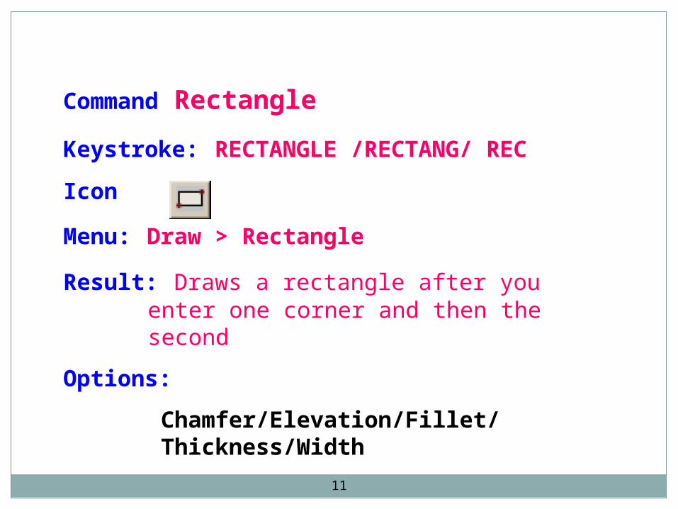
Command Rectangle
Keystroke: RECTANGLE /RECTANG/ REC
Icon
Menu: Draw > Rectangle
Result: Draws a rectangle after you enter one corner and then the second
Options:
Chamfer/Elevation/Fillet/Thickness/Width
12
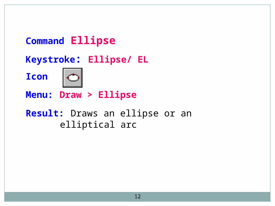
Command Ellipse
Keystroke: Ellipse/ EL
Icon
Menu: Draw > Ellipse
Result: Draws an ellipse or an elliptical arc
13
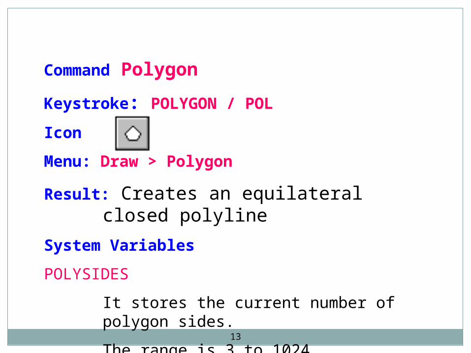
Command Polygon
Keystroke: POLYGON / POL
Icon
Menu: Draw > Polygon
Result: Creates an equilateral closed polyline
System Variables
POLYSIDES
It stores the current number of polygon sides.
The range is 3 to 1024.
14
Command SKETCH
Command line: sketch
Result Creates a series of freehand line segments
Notes
• Drawing with the SKETCH command controls a screen-based pen with a pointing device.
• SKETCH is useful for entering map outlines, signatures, or other freehand drawings.
• Sketched lines are not added to the drawing until they are recorded.
15
Command Spline
Keystroke: Spline / spl
Icon
Menu: Draw > Spline
Result: Creates a quadratic or cubic spline curve
Notes:
• SPLINE fits a smooth curve to a sequence of points within a specified tolerance.
• AutoCAD uses NURBS (nonuniform rational B-splines) mathematics, which stores and defines a class of curve and surface data.
16
Command Name Donut
Command line: Donut
Draw menu: Donut
Result: Draws filled circles and rings.
Fill Command
Controls the filling of multilines, traces, solids, all hatches, and wide polylines
Command line: fill (or 'fill for transparent use)
OPTIONS command [or from tool menu] displays the Options dialog box, in which you can set Fill mode and other display settings.
17
Command Name Solid
Command line: solid
Draw menu > Surfaces > 2D Solid
Surfaces toolbar:
Result: Creates solid-filled polygons.
18
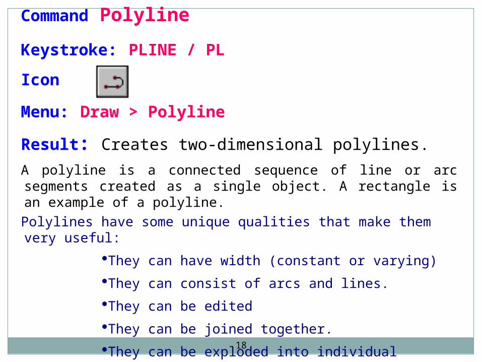
Command Polyline
Keystroke: PLINE / PL
Icon
Menu: Draw > Polyline
Result: Creates two-dimensional polylines.
A polyline is a connected sequence of line or arc segments created as a single object. A rectangle is an example of a polyline.
Polylines have some unique qualities that make them very useful:
They can have width (constant or varying)
They can consist of arcs and lines.
They can be edited
They can be joined together.
They can be exploded into individual segments
19
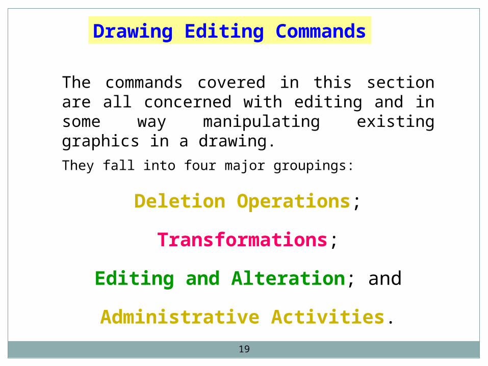
The commands covered in this section are all concerned with editing and in some way manipulating existing graphics in a drawing.
They fall into four major groupings:
Deletion Operations;
Transformations;
Editing and Alteration; and
Administrative Activities.
Drawing Editing Commands
20
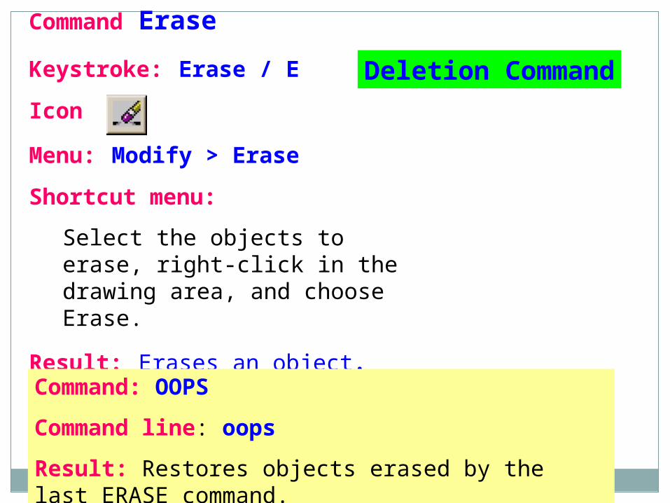
Command Erase
Keystroke: Erase / E
Icon
Menu: Modify > Erase
Shortcut menu:
Select the objects to erase, right-click in the drawing area, and choose Erase.
Result: Erases an object.
Command: OOPS
Command line: oops
Result: Restores objects erased by the last ERASE command.
Deletion Command
21
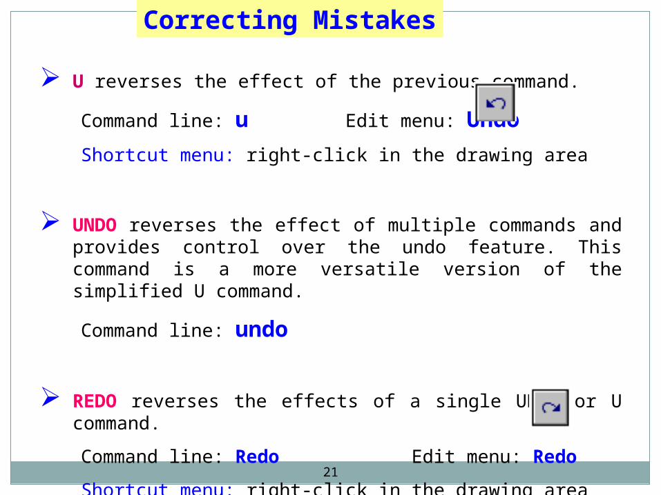
U reverses the effect of the previous command.
Command line: u Edit menu: Undo
Shortcut menu: right-click in the drawing area
UNDO reverses the effect of multiple commands and provides control over the undo feature. This command is a more versatile version of the simplified U command.
Command line: undo
REDO reverses the effects of a single UNDO or U command.
Command line: Redo Edit menu: Redo
Shortcut menu: right-click in the drawing area
Correcting Mistakes
22
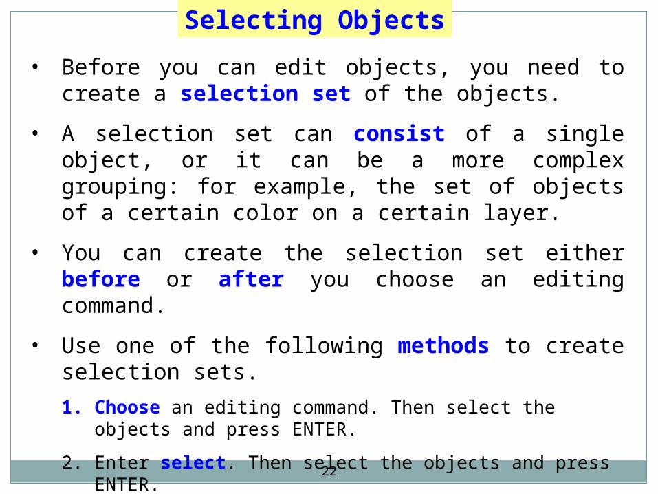
Selecting Objects
• Before you can edit objects, you need to create a selection set of the objects.
• A selection set can consist of a single object, or it can be a more complex grouping: for example, the set of objects of a certain color on a certain layer.
• You can create the selection set either before or after you choose an editing command.
• Use one of the following methods to create selection sets.
1. Choose an editing command. Then select the objects and press ENTER.
2. Enter select. Then select the objects and press ENTER.
3. Select the objects with the pointing device. Then choose an editing command.
4. Define groups.
23
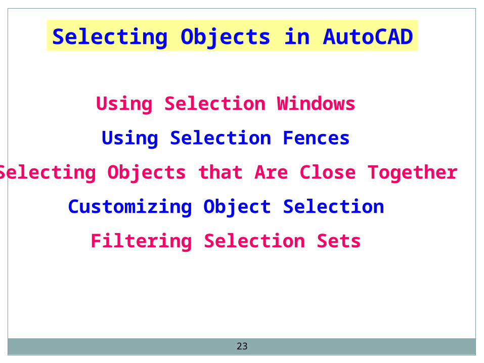
Using Selection Windows
Using Selection Fences
Selecting Objects that Are Close Together
Customizing Object Selection
Filtering Selection Sets
Selecting Objects in AutoCAD
24
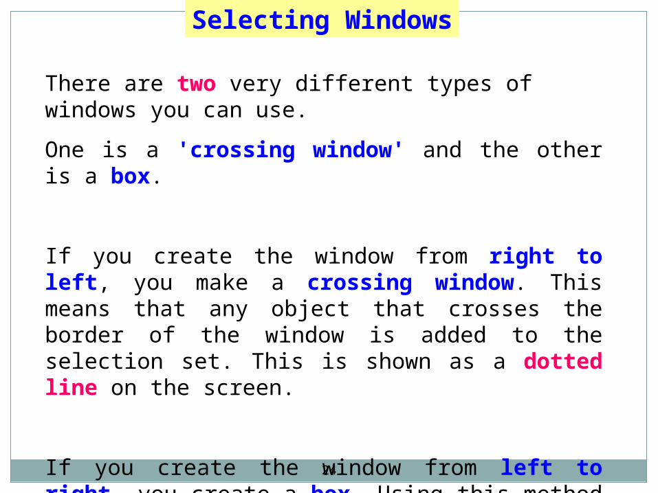
Selecting Windows
There are two very different types of windows you can use.
One is a 'crossing window' and the other is a box.
If you create the window from right to left, you make a crossing window. This means that any object that crosses the border of the window is added to the selection set. This is shown as a dotted line on the screen.
If you create the window from left to right, you create a box. Using this method you'll add only the items that are completely within the box. This is shown as a solid line on the screen.
25
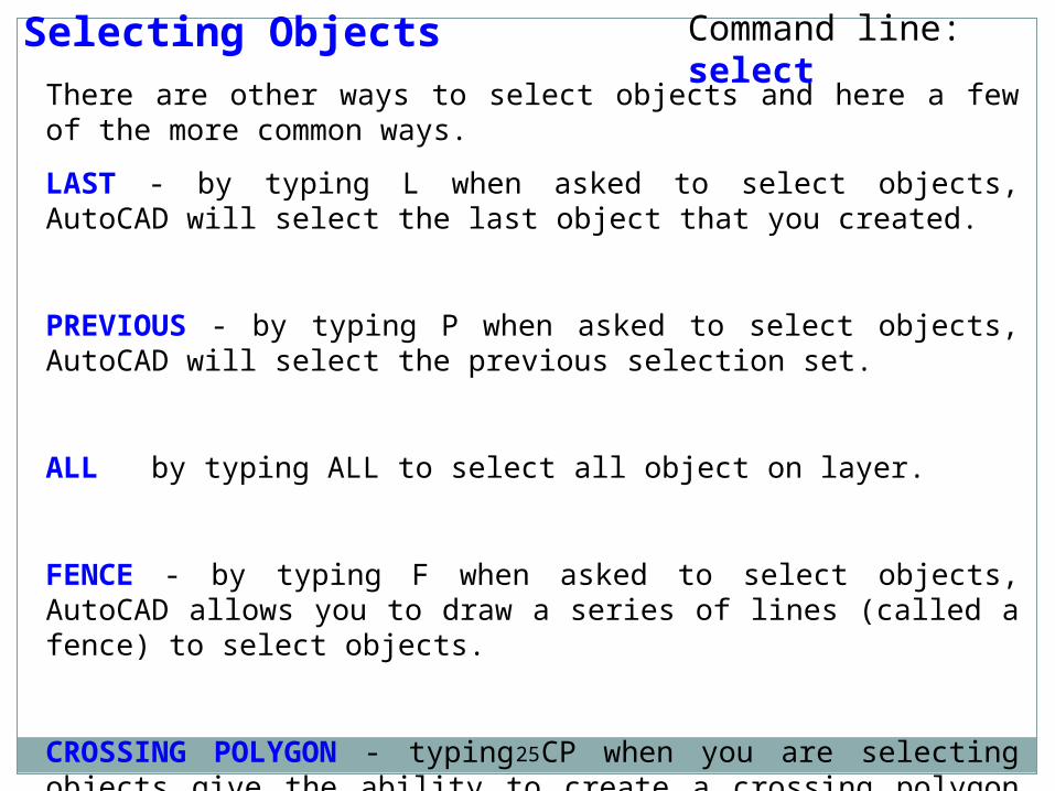
Selecting Objects
There are other ways to select objects and here a few of the more common ways.
LAST - by typing L when asked to select objects, AutoCAD will select the last object that you created.
PREVIOUS - by typing P when asked to select objects, AutoCAD will select the previous selection set.
ALL by typing ALL to select all object on layer.
FENCE - by typing F when asked to select objects, AutoCAD allows you to draw a series of lines (called a fence) to select objects.
CROSSING POLYGON - typing CP when you are selecting objects give the ability to create a crossing polygon for object selection. This is similar to a crossing box, but you can pick points on the screen to create a polygon.
Command line: select
26
Repeating Commands
You can repeat AutoCAD commands using one of several methods.
To repeat the last command
• Press ENTER or SPACEBAR, or right-click in the drawing area and choose Repeat.
To repeat one of the last six commands
1. Right-click in the command window or text window.
2. From the shortcut menu, choose Recent Commands, then choose one of the six most recently used commands.
To repeat the same command multiple times
1. At the Command prompt, enter multiple.
2. At the next prompt, enter the command you want to repeat.
3. AutoCAD repeats this command until you press ESC.
27
Canceling Commands
You can cancel any command by pressing ESC, the standard key to cancel actions in Windows programs.
You can change the cancel key to CTRL+C, which was used to cancel commands in previous AutoCAD releases.
To change the cancel key
1. From the Tools menu, choose Options.
2. In the Options dialog box, choose the User Preferences tab.
3. Under Windows Standard Behavior, clear Windows Standard Accelerator Keys.
28
TEXT or DTEXTCreates one or more lines of text and end each line when you press ENTER. Each text line is a separate object that you can relocate, reformat, or otherwise modify.
Text Commands
SpellChecks spelling in a drawingTools menu: Spelling Command line: spell (or 'spell for transparent use)
MTEXT • Multiline Text Editor creates paragraphs that fit within a nonprinting text
boundary.• You create the text boundary to define the width of the paragraph.• You can also specify the justification, style, height, rotation, width, color,
spacing, and other text attributes using MTEXT.• Each mtext object is a single object, regardless of the number of lines it
contains.
29
Basic Utility Commands
REDRAW
This command forces AutoCAD to re-display the graphics on the screen. This has the effect of clearing away some extraneous graphics such as marker "blips" that are left behind by pointing operations. (Blipmode=on or off)
SAVE Causes all editing changes to the current drawing to be saved to the disk file. Should be done regularly during a long drawing session.
END Terminates the drawing editor, saves the current drawing to a disk file and returns to the main AutoCAD menu.
QUIT Terminates the drawing editor without saving the changes made to the current drawing. Returns to the main AutoCAD menu.


