60
AutoBoom™ Installation Manual CaseIH 3150/3185, Pre-2002 Tyler Patriot Open Center

AutoBoom™ Installation Manual
CaseIH 3150/3185, Pre-2002 Tyler PatriotOpen Center

While every effort has been made to ensure the accuracy of this document, Raven Industries assumes no responsibility for omissions and errors. Nor is any liability assumed for damages resulting from the use of information contained herein.
Raven Industries shall not be held responsible or liable for the effects of atmospheric conditions and sunspot activity on the performance of our products.
Raven Industries cannot guarantee the accuracy, integrity, continuity, or availability of the GPS signal from the U.S. Department of Defense/NAVSTAR GPS satellites, the OmniSTAR correction service or the WAAS correction service.
Raven Industries accepts no responsibility for the use of the signal for other than the stated purpose. Raven Industries shall not be responsible or liable for incidental or consequential damages or a loss of anticipated benefits or profits, work stoppage or loss or impairment of data arising out of the use, or inability to use, the SmarTrax or any of its components.
Disclaimer

Table of Contents
Manual No. 016-0230-005 i
Chapter 1 Important Safety Information................................................. 1Important Safety Information ..................................................................................................... 1
Hydraulic Safety .................................................................................................................. 2Electrical Safety ................................................................................................................... 2
Chapter 2 Introduction............................................................................. 3Introduction ............................................................................................................................... 3
Recommendations .............................................................................................................. 4Preparing for Installation ..................................................................................................... 4Point of Reference ............................................................................................................... 4Hydraulic Fittings ................................................................................................................. 4
Chapter 3 PowerGlide Plus ..................................................................... 5PowerGlide Plus Kit Contents ................................................................................................... 5Install the PowerGlide Plus Hydraulic System .......................................................................... 9
Install Fittings on the AutoBoom Valve ................................................................................ 9Mount the AutoBoom Valve ................................................................................................. 9Install the Pressure Hoses ............................................................................................... 10Install the Tank Hoses - CaseIH and Patriot 1997 & Newer Only ..................................... 11Install Left and Right Cylinder Hoses ................................................................................ 13Install the Down Hoses ...................................................................................................... 14PowerGlide Plus Hydraulic Schematic .............................................................................. 15
Install the Gauge Wheels ........................................................................................................ 16Mount the Gauge Wheels .................................................................................................. 16
Install the PowerGlide Plus Wiring .......................................................................................... 17Install the AutoBoom Node ................................................................................................ 17Connect the Harness to the Boom Function Controls ....................................................... 18Connect the Harness Cable .............................................................................................. 18Connect the Controller (If Applicable) ............................................................................... 19Connect the Computer (If Applicable) ............................................................................... 19Connect the Power Leads ................................................................................................. 19
PowerGlide Plus Wiring Schematics ....................................................................................... 20AutoBoom Controller ......................................................................................................... 20Envizio Plus ....................................................................................................................... 21SCS 4000/5000 ................................................................................................................. 22Viper Pro & Envizio Pro ..................................................................................................... 23
Chapter 4 UltraGlide............................................................................... 25UltraGlide Kit Contents ............................................................................................................ 25Install the UltraGlide Hydraulic System ................................................................................... 29
Install Fittings on the AutoBoom Valve .............................................................................. 29Mount the AutoBoom Valve ............................................................................................... 30

Table of Contents
ii CaseIH 3150/3185, Pre-2002 Tyler Patriot Open Center
Install the Pressure Hoses ................................................................................................31Install the Tank Hoses - CaseIH and Patriot 1997 & Newer Only ...................................... 32Install Left and Right Cylinder Hoses ................................................................................33Install the Down Hoses ......................................................................................................34UltraGlide Hydraulic Schematic ......................................................................................... 35
Install the UltraGlide Sensors ..................................................................................................36Mount the UltraGlide Sensors ...........................................................................................36Connect the Sensor Cables ...............................................................................................37
Install the Gauge Wheels - Optional ........................................................................................38Mount the Gauge Wheels ..................................................................................................38
Install the UltraGlide Wiring .....................................................................................................39Install the AutoBoom Node ................................................................................................ 39Connect the Harness to the Boom Function Controls ....................................................... 40Install the Center Rack Control ..........................................................................................41Connect the Harness Cable ..............................................................................................42Connect the Controller (If Applicable) ................................................................................ 42Connect the Computer (If Applicable) ...............................................................................42Connect the Power Leads .................................................................................................42
UltraGlide Wiring Schematics ..................................................................................................43AutoBoom Controller .........................................................................................................43Envizio Plus ....................................................................................................................... 44SCS 4000/5000 .................................................................................................................45Viper Pro & Envizio Pro .....................................................................................................46
Chapter 5 Replacement Parts ............................................................... 49Valve Blocks ............................................................................................................................49
PowerGlide Plus Valve Block Replacement Parts ............................................................. 49UltraGlide Valve Block Replacement Parts ....................................................................... 50
Wheel and Assembly Brackets ................................................................................................51Machine-Specific Wheels and Brackets ............................................................................ 51Cushioned Axle .................................................................................................................51
Sensors and Brackets .............................................................................................................52Molded Sensor Replacement Parts ...................................................................................52Machine-Specific Sensor U-Bolts ......................................................................................52

CHAPTER
1
Manual No. 016-0230-005 1
Chapter 1Important Safety Information
Important Safety Information
Read this manual and the operation and safety instructions included with your implement and/or controller carefully before installing the AutoBoom™ system.
• Follow all safety information presented within this manual.• If you require assistance with any portion of the installation or service of your Raven equipment, contact
your local Raven dealer for support.• Follow all safety labels affixed to the AutoBoom system components. Be sure to keep safety labels in good
condition and replace any missing or damaged labels. To obtain replacements for missing or damaged safety labels, contact your local Raven dealer.
When operating the machine after installing AutoBoom, observe the following safety measures:
• Be alert and aware of surroundings.• Do not operate AutoBoom or any agricultural equipment while under the influence of alcohol or an illegal
substance.• Remain in the operator’s position in the machine at all times when AutoBoom is engaged.• Disable AutoBoom when exiting from the operator’s seat and machine.• Do not drive the machine with AutoBoom enabled on any public road.• Determine and remain a safe working distance from other individuals. The operator is responsible for
disabling AutoBoom when the safe working distance has been diminished.• Ensure AutoBoom is disabled prior to starting any maintenance work on AutoBoom or the machine.
NOTICE

Chapter 1
2 CaseIH 3150/3185, Pre-2002 Tyler Patriot Open Center
• When starting the machine for the first time after installing AutoBoom, be sure that all persons stand clear, in case a hose has not been properly tightened.
• The machine must remain stationary and switched off, with the booms unfolded and supported while installation or maintenance is conducted.
Hydraulic Safety• Raven Industries recommends that appropriate protective equipment be worn at all times when working on
the hydraulic system.• Never attempt to open or work on a hydraulic system with the equipment running. Care should always be
taken when opening a system that has been previously pressurized.• When disconnecting the hydraulic hoses or purging is required, be aware that the hydraulic fluid may be
extremely hot and under high pressure. Caution must be exercised.• Any work performed on the hydraulic system must be done in accordance with the machine manufacturer’s
approved maintenance instructions.• When installing AutoBoom hydraulics or performing diagnostics, maintenance, or routine service, ensure
that precautions are taken to prevent any foreign material or contaminants from being introduced into the machine’s hydraulic system. Objects or materials that are able to bypass the machine’s hydraulic filtration system will adversely reduce performance and possibly damage the AutoBoom hydraulic valves.
Electrical Safety• Always verify that the power leads are connect to the correct polarity as marked. Reversing the power leads
could cause severe damage to the equipment.• Ensure that the power cable is the last cable to be connected.
WARNING
CAUTION

CHAPTER
2
Manual No. 016-0230-005 3
Chapter 2Introduction
IntroductionCongratulations on your purchase of the Raven AutoBoom system! This system is designed to provide automated boom height adjustment for agricultural spraying equipment.
This manual applies to the following machines. For future reference, write your serial number in the space below.
MAKE: CaseIH, PatriotMODEL: CaseIH 3150/3185, Pre-2002 PatriotYEAR: SERIAL NUMBER:
FIGURE 1. CaseIH 3185
Note: This manual contains the installation instructions for the PowerGlide Plus and UltraGlide systems. Be sure to identify which system you have and follow only the instructions for that system.

Chapter 2
4 CaseIH 3150/3185, Pre-2002 Tyler Patriot Open Center
RecommendationsRaven Industries recommends the following best practices when installing the AutoBoom system:
• Use part numbers to identify the parts.• Do not remove the plastic wrap from a part until it is necessary for installation.• Do not remove plastic caps from a part until it is necessary for installation.
Tools NeededThe following tools are recommended for installation of the AutoBoom system:
• SAE standard-sized wrenches• Cable ties• Set of tools
Preparing for InstallationBefore installing AutoBoom, park the machine where the ground is level, clean, and dry. Leave the machine turned off for the duration of the installation process.
During the installation process, follow good safety practices. Be sure to carefully read the instructions in this manual as you complete the installation process.
Point of ReferenceThe instructions in this manual assume that you are standing behind the machine, looking toward the cab.
Hydraulic FittingsThis manual may reference the following types of hydraulic fittings:
• SAE O-ring fittings• ORFS (O-Ring Face Seal) fittings• JIC fittings
JIC fitting (M)ORFS fittingSAE O-ring fitting

CHAPTER
3
Manual No. 016-0230-005 5
Chapter 3PowerGlide Plus
PowerGlide Plus Kit ContentsThis section contains a list of the components that are included in the PowerGlide Plus AutoBoom kit. Before beginning the AutoBoom installation, compare the items in the AutoBoom kit with the components list. If you have questions about the kit, contact your Raven dealer.
TABLE 1. PowerGlide Plus Installation Kit (P/N 117-0231-005)
Picture Item Description Part Number Qty.
Not Pictured Manual - CaseIH 3150/3185, Pre-2002 Patriot AutoBoom Installation 016-0230-005 1
Valve - PowerGlide Plus AutoBoom 063-0131-117 1
Plate - Hydraulic Block Mounting 107-0171-619 1
Cable - Case Adapter 115-0171-558 4
Fitting - 3/4” SAE O-Ring (M) to 9/16” JIC (M) .031 Orifice Straight Adapter 333-0012-230 2
U-Bolt - 2-1/16” W x 3” L x 3/8” Thread 107-0171-609 2

Chapter 3
6 CaseIH 3150/3185, Pre-2002 Tyler Patriot Open Center
Bolt - 5/16”-24 x 1” Grade 8 Hex 311-0049-235 4
Nut - 3/8”-16 Zinc Flanged Lock 312-1001-164 4
Washer - 5/16” Zinc Plated Lock 313-1000-019 4
TABLE 2. Hydraulic Kit (P/N 117-0134-005)
Picture Item Description Part Number Qty.
Fitting - 3/4” JIC M/M/F Swivel Run Tee 333-0012-039 1
Fitting - 7/16” JIC (M) to 9/16” SAE O-Ring (M) Straight Adapter 333-0012-044 2
Fitting - 9/16” JIC (M) to 9/16” SAE O-Ring (M) Straight Adapter 333-0012-045 2
Fitting - 3/4” SAE O-Ring (M) to 3/4” JIC (M) Straight Adapter 333-0012-093 3
Fitting - 1-1/16” JIC M/F 90° Swivel Elbow 333-0012-099 1
Fitting - 1-1/16” JIC M/M/F Swivel Run Tee 333-0012-109 1
Fitting - 3/8” NPT (M) to 9/16” JIC (M) Straight Adapter 333-0012-123 2
TABLE 1. PowerGlide Plus Installation Kit (P/N 117-0231-005)
Picture Item Description Part Number Qty.

3
Manual No. 016-0230-005 7
PowerGlide Plus
Fitting - 9/16” JIC (F) to 7/16” JIC (M) Straight Adapter 333-0012-159 2
Fitting - 3/8” NPT Breather 333-0012-196 2
Fitting - 9/16” SAE O-Ring to 3/8” NPT (F) Straight Adapter 333-0012-197 2
Hydraulic Hose - 3/4” JIC 90° (F) to 3/4” JIC (F) - 72” 214-1000-302 2
Hydraulic Hose - 9/16” JIC 90° (F) to 9/16” JIC (F) - 192” 214-1000-303 2
Hydraulic Hose - 3/4” JIC 90° (F) to 1-1/16” JIC (F) - 180” 214-1000-304 1
TABLE 3. PowerGlide Plus Wheel Kit (P/N 117-0133-005)
Picture Item Description Part Number Qty.
Axle Assembly - Right Offset Cushioned 063-0131-589 1
Axle Assembly - Left Offset Cushioned 063-0131-590 1
Bracket - Left Weldment 116-0159-625 1
Bracket - Right Weldment 116-0159-626 1
TABLE 2. Hydraulic Kit (P/N 117-0134-005)
Picture Item Description Part Number Qty.

Chapter 3
8 CaseIH 3150/3185, Pre-2002 Tyler Patriot Open Center
Wheel 322-0131-008 2
U-Bolt - 2-1/16” W x 3” L x 3/8” Thread 107-0171-609 6
Bolt - 1/2”-13 x 1-1/2” SS Hex 311-0058-186 4
Nut - 1/2”-13 Zinc Hex 312-1001-043 4
Nut - 3/8”-16 Zinc Flanged Lock 312-1001-164 12
TABLE 4. PowerGlide Plus Wiring Kit (P/N 117-0137-023)
Picture Item Description Part Number Qty.
Not Pictured CAN AutoBoom Calibration & Operation Manual 016-0130-062 1
AutoBoom PowerGlide Plus CAN Node 063-0130-010 1
Cable - Harness 115-0230-045 1
Cable - Power/CAN 115-0230-007 1
TABLE 3. PowerGlide Plus Wheel Kit (P/N 117-0133-005)
Picture Item Description Part Number Qty.
3
Manual No. 016-0230-005 9
PowerGlide Plus
Install the PowerGlide Plus Hydraulic System
Install Fittings on the AutoBoom Valve
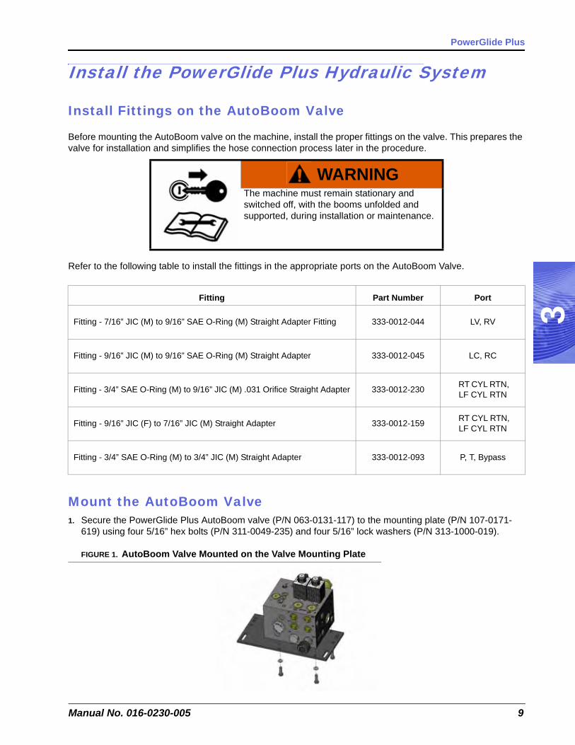
Before mounting the AutoBoom valve on the machine, install the proper fittings on the valve. This prepares the valve for installation and simplifies the hose connection process later in the procedure.
Refer to the following table to install the fittings in the appropriate ports on the AutoBoom Valve.
Mount the AutoBoom Valve1. Secure the PowerGlide Plus AutoBoom valve (P/N 063-0131-117) to the mounting plate (P/N 107-0171-
619) using four 5/16” hex bolts (P/N 311-0049-235) and four 5/16” lock washers (P/N 313-1000-019).
FIGURE 1. AutoBoom Valve Mounted on the Valve Mounting Plate
WARNINGThe machine must remain stationary and switched off, with the booms unfolded and supported, during installation or maintenance.
Fitting Part Number Port
Fitting - 7/16” JIC (M) to 9/16” SAE O-Ring (M) Straight Adapter Fitting 333-0012-044 LV, RV
Fitting - 9/16” JIC (M) to 9/16” SAE O-Ring (M) Straight Adapter 333-0012-045 LC, RC
Fitting - 3/4” SAE O-Ring (M) to 9/16” JIC (M) .031 Orifice Straight Adapter 333-0012-230 RT CYL RTN, LF CYL RTN
Fitting - 9/16” JIC (F) to 7/16” JIC (M) Straight Adapter 333-0012-159 RT CYL RTN, LF CYL RTN
Fitting - 3/4” SAE O-Ring (M) to 3/4” JIC (M) Straight Adapter 333-0012-093 P, T, Bypass

Chapter 3
10 CaseIH 3150/3185, Pre-2002 Tyler Patriot Open Center
2. Secure the mounting plate to the cross rail behind the sprayer’s tank using two 2-1/16” W x 3” L x 3/8” thread U-bolts (P/N 107-0171-609) and four 3/8” zinc flanged lock nuts (P/N 312-1001-164).
FIGURE 2. AutoBoom Valve Mounted on the Sprayer
Install the Pressure Hoses
WARNINGHydraulics are under pressure. Care should always be taken with a system that has been pressurized. When disconnecting or purging hydraulic hoses, be aware that the hydraulic fluid within the machine’s system may be extremely hot and under high pressure.
CAUTIONWhen installing AutoBoom hydraulics or performing diagnostics, maintenance, or routine service, ensure precautions are taken to prevent any foreign material or contaminants from being introduced into the machine’s hydraulic system.
Objects or materials that are able to bypass the machine’s hydraulic filtration system will reduce performance and possibly damage the AutoBoom hydraulic valves.
Part NumberMachine AutoBoom Valve
Hose End Location Hose End Location214-1000-302 3/4” JIC (F) Steel Pressure Line 3/4” JIC (F) 90° P
214-1000-304 1-1/16” JIC (F) Return Bank 3/4” JIC (F) 90° T

3
Manual No. 016-0230-005 11
PowerGlide Plus
FIGURE 3. Pressure Hose Installed
1. Locate the pressure line on the machine’s hydraulic valve (Port P).2. Trace the pressure line back to the point it joins the steel hydraulic line.3. Disconnect the pressure line from the steel line.4. Connect the end of the pressure line to the Bypass Port on the AutoBoom valve.5. Connect the straight end of the supplied hydraulic hose (P/N 214-1000-302) to the machine’s steel line.6. Connect the 90° end of the installed hose to Port P on the AutoBoom valve.
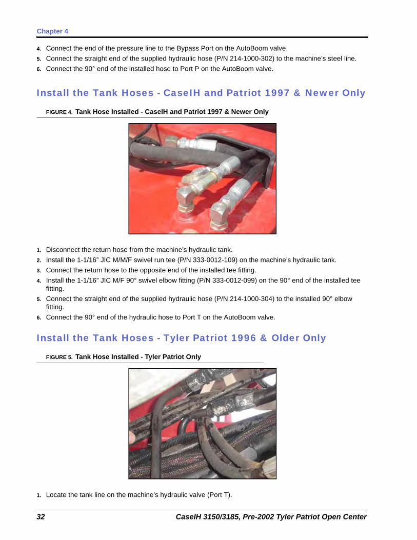
Install the Tank Hoses - CaseIH and Patriot 1997 & Newer Only
FIGURE 4. Tank Hose Installed - CaseIH and Patriot 1997 & Newer Only
7. Disconnect the return hose from the machine’s hydraulic tank.8. Install the 1-1/16” JIC M/M/F swivel run tee (P/N 333-0012-109) on the machine’s hydraulic tank.9. Connect the return hose to the opposite end of the installed tee fitting.10. Install the 1-1/16” JIC M/F 90° swivel elbow fitting (P/N 333-0012-099) on the 90° end of the installed tee
fitting.11. Connect the straight end of the supplied hydraulic hose (P/N 214-1000-304) to the installed 90° elbow
fitting.12. Connect the 90° end of the hydraulic hose to Port T on the AutoBoom valve.
New Pressure Hose
Bypass (Original Pressure Line)

Chapter 3
12 CaseIH 3150/3185, Pre-2002 Tyler Patriot Open Center
Install the Tank Hoses - Tyler Patriot 1996 & Older Only
FIGURE 5. Tank Hose Installed - Tyler Patriot 1996 & Older Only
1. Locate the tank line on the machine’s hydraulic valve (Port T).2. Trace the tank line back to the point it joins the steel hydraulic line.3. Disconnect the tank line from the steel line.4. Install the 3/4” JIC M/M/F swivel run tee (P/N 333-0012-039) on the machine’s steel hydraulic line.5. Connect the tank line to the opposite end of the installed tee fitting.6. Connect the straight end of the supplied hydraulic hose (P/N 214-1000-302) to the 90° end of the installed
tee fitting.7. Connect the 90° end of the hydraulic hose to Port T on the AutoBoom valve.

3
Manual No. 016-0230-005 13
PowerGlide Plus
Install Left and Right Cylinder Hoses
1. Disconnect the cylinder hoses from the rod-end of the machine’s tilt cylinders.2. Route the right cylinder hose back to the AutoBoom valve and connect it to Port RV.3. Route the left cylinder hose back to the AutoBoom valve and connect it to Port LV on the AutoBoom valve.
FIGURE 6. Raise Hoses Installed on the Tilt Cylinder
4. Remove the fittings from the rod-end of the tilt cylinders.5. Install the 3/8” NPT (M) to 9/16” JIC (M) straight adapter fittings (P/N 333-0012-123) into the rod-end tilt
cylinder ports.6. Connect the straight end of the supplied hydraulic hose (P/N 214-1000-303) in the installed fitting in the rod-
end of the machine’s right tilt cylinder.7. Connect the 90° end of the hydraulic hose to Port RC on the AutoBoom valve.8. Connect the straight end of the supplied hydraulic hose (P/N 214-1000-303) in the installed fitting in the rod-
end of the machine’s left tilt cylinder.9. Connect the 90° end of the hydraulic hose to Port LC on the AutoBoom valve.
Part NumberMachine AutoBoom Valve
Hose End Location Hose End Location214-1000-303 9/16” JIC (F) Left Tilt Cylinder 3/4” JIC (F) 90° LC
214-1000-303 9/16” JIC (F) Right Tilt Cylinder 3/4” JIC (F) 90° RC

Chapter 3
14 CaseIH 3150/3185, Pre-2002 Tyler Patriot Open Center
Install the Down Hoses
FIGURE 7. Installed Down Hoses
1. Disconnect the hose from the base-end of the machine’s left tilt cylinder.2. Route the hose to the AutoBoom valve and connect it to the installed fitting in the RT CYL RTN Port.3. Disconnect the hose from the base-end of the machine’s right tilt cylinder.4. Route the hose to the AutoBoom valve and connect it to the installed fitting in the LF CYL RTN Port.
FIGURE 8. Installed Breathers
5. Remove the cylinder down fittings from the base-end of the tilt cylinders.6. Install two 9/16” SAE O-ring (M) to 3/8” NPT (F) straight adapter fittings (P/N 333-0012-197) in the base-end
of the tilt cylinders.7. Install the 3/8” NPT breather fittings (P/N 333-0012-196) into the installed adapters.
Installed Down Hoses
Installed Breather Fittings

3
Manual No. 016-0230-005 15
PowerGlide Plus
PowerGlide Plus Hydraulic Schematic

Chapter 3
16 CaseIH 3150/3185, Pre-2002 Tyler Patriot Open Center
Install the Gauge Wheels
Mount the Gauge Wheels
Note: Wheel mounting locations may be influenced by the boom configuration. Verify that the wheels will not interfere with or be damaged by folding or unfolding the booms.
Determine an appropriate location for mounting a wheel on the boom. The wheel should be mounted outside of the boom fold, but inside the boom breakaway.
FIGURE 9. Gauge Wheel Installed (Back View)
1. Remove the nuts from the right wheel axle (P/N 063-0131-589).2. Place the wheel (P/N 322-0131-008) on the right wheel axle.3. Reinstall the lug nuts on the wheel axle to secure the wheel.4. Attach the right wheel mounting bracket (P/N 116-0159-626) to the front of the right boom by installing three
2-1/16” W x 3” L x 3/8” thread U-bolts (P/N 107-0171-609) through the back of the mounting bracket and securing them with six 3/8” zinc flanged lock nuts (P/N 312-1001-164).
5. Insert the right wheel axle into the right wheel mounting bracket, positioning it so that the bottom of the wheel touches the ground (or nearly so).
6. Secure the gauge wheel assembly in the wheel mounting bracket by installing two 1/2”-13 x 1-1/2” SS hex bolts (P/N 311-0058-186) and two 1/2” zinc hex nuts (P/N 312-1001-043).
7. Repeat the steps above to install the left wheel.
WARNINGThe machine must remain stationary and switched off, with the booms unfolded and supported, while installation or maintenance is conducted.

3
Manual No. 016-0230-005 17
PowerGlide Plus
Install the PowerGlide Plus WiringWiring Connections
Note: For wiring connections made outside the cab, apply dielectric silicone grease (P/N 222-0000-006) generously on both the male and female ends of the connectors. Application of the grease will prevent corrosion to the pins and wires.
Install the AutoBoom Node
FIGURE 10. PowerGlide Plus AutoBoom Node Installed
1. Mount the AutoBoom node (P/N 063-0130-010) to the cross beam of the machine’s center rack within a close proximity (3 feet/1 meter) to the AutoBoom valve.
Note: Position the node so that the cable connectors face down.
2. Insert the large, rectangular node connector on the harness cable (P/N 115-0230-045) into the left port of the AutoBoom node.
3. Tighten the bolt on the node connector to secure.
CAUTIONAlways connect the power cable as the last step in the wiring process and verify that the power leads are connected with the correct polarity. Reversing power leads can cause severe damage to the equipment.

Chapter 3
18 CaseIH 3150/3185, Pre-2002 Tyler Patriot Open Center
Connect the Harness to the Boom Function Controls
Complete the following steps to connect the harness to the machine’s boom function coils.
1. On the harness cable (P/N 115-0230-045), locate the Left Solenoid connector and connect it to Port 4A on the AutoBoom valve.
2. Connect the Right Solenoid connector to Port 4B on the AutoBoom valve.3. Connect the Left Prop connector to Port 5A on the AutoBoom valve.
FIGURE 11. Machine’s Left and Right Tilt Boom Function Coils
4. Locate the machine boom function coils near the machine’s boom stack valve.5. Disconnect the connector from the machine’s Left Tilt Up coil.6. Install a boom sense adapter cable (P/N 115-0171-558) between the coil and the machine’s coil connector.7. Connect boom sense adapter cables between the Left Tilt Down, Right Tilt Up, and Right Tilt Down coils
and the coil connectors.8. On the harness cable, locate the Left Solenoid Sense connectors. Isolate the connector labeled Up and
connect it to the Left Tilt Up coil via the installed boom sense adapter cable.9. Connect the Down Left Solenoid Sense connector to the Left Tilt Down coil via the installed boom sense
adapter cable.10. Connect the Right Solenoid Sense connectors to the machine’s Right Tilt Up and Right Tilt Down coils via
the installed boom sense adapter cables.
Connect the Harness Cable1. Route the harness cable (P/N 115-0230-045) toward the machine’s cab.2. Connect the harness cable to the controller cable (P/N 115-0230-007).3. Tighten the connector screw cap to secure the connection.
Note: Be sure to allow enough slack in the harness cable to allow for boom racking.
3
Manual No. 016-0230-005 19
PowerGlide Plus
Connect the Controller (If Applicable)1. Route the controller cable (P/N 115-0230-007) into the right side of the machine’s cab.2. Locate the two controller connectors. Connect these connectors to the AutoBoom controller (P/N 063-0130-
011).
Note: The AutoBoom controller should be mounted in the machine’s cab so that the machine operator has easy access to it.
Connect the Computer (If Applicable)
Refer to the Installation & Operation Manual and the appropriate wiring schematic beginning on page 20 for installation and wiring instructions for your specific field computer.
Connect the Power Leads1. Locate the power cable that has the red and white power leads at one end.2. Disconnect the machine’s connectors from the battery terminals.3. Install the red power lead on the positive battery terminal and reinstall the machine’s battery connector.4. Install the white power lead on the negative battery terminal and reinstall the machine’s battery connector.

Chapter 3
20 CaseIH 3150/3185, Pre-2002 Tyler Patriot Open Center
PowerGlide Plus Wiring Schematics
AutoBoom Controller

3
Manual No. 016-0230-005 21
PowerGlide Plus
Envizio Plus

Chapter 3
22 CaseIH 3150/3185, Pre-2002 Tyler Patriot Open Center
SCS 4000/5000

3
Manual No. 016-0230-005 23
PowerGlide Plus
Viper Pro & Envizio Pro

Chapter 3
24 CaseIH 3150/3185, Pre-2002 Tyler Patriot Open Center

CHAPTER
4
Manual No. 016-0230-005 25
Chapter 4UltraGlide
UltraGlide Kit ContentsThis section contains a list of the components that are included in the UltraGlide AutoBoom kit. Before beginning the AutoBoom installation, compare the items in the AutoBoom kit with the components on this list. If you have questions about the kit, contact your Raven dealer.
TABLE 1. UltraGlide Installation Kit (P/N 117-0232-005)
Picture Item Description Part Number Qty.
Not Pictured Manual - CaseIH 3150/3185, Pre-2002 Patriot AutoBoom Installation 016-0230-005 1
Valve - UltraGlide AutoBoom 063-0131-116 1
Plate - Hydraulic Block Mounting 107-0171-619 1
Sensor - Right Ultrasonic 063-0130-012 1
Sensor - Left Ultrasonic 063-0130-014 1
Sensor - Center Ultrasonic 063-0130-018 1

Chapter 4
26 CaseIH 3150/3185, Pre-2002 Tyler Patriot Open Center
Cable - Case Boom Sense Adapter 115-0171-558 5
Cable - Center Rack Control Weatherpack Boom Sense Adapter 115-0230-037 2
Fitting - 3/4” SAE O-Ring (M) to 9/16” JIC (M) .031 Orifice Straight Adapter 333-0012-230 2
U-Bolt - 2-1/16” W x 3” L x 3/8” Thread 107-0171-609 8
Bolt - 5/16”-24 x 1” Grade 8 Hex 311-0049-235 4
Nut - 3/8”-16 Zinc Flanged Lock 312-1001-164 20 (4 extra)
Washer - 5/16” Zinc Plated Lock 313-1000-019 4
TABLE 2. Hydraulic Kit (P/N 117-0137-005)
Picture Item Description Part Number Qty.
Fitting - 3/4” JIC M/M/F Swivel Run Tee 333-0012-039 1
Fitting - 7/16” JIC (M) to 9/16” SAE O-Ring (M) Straight Adapter 333-0012-044 2
Fitting - 9/16” JIC (M) to 9/16” SAE O-Ring (M) Straight Adapter 333-0012-045 2
TABLE 1. UltraGlide Installation Kit (P/N 117-0232-005)
Picture Item Description Part Number Qty.

4
Manual No. 016-0230-005 27
UltraGlide
Fitting - 3/4” SAE O-Ring (M) to 3/4” JIC (M) Straight Adapter 333-0012-093 3
Fitting - 1-1/16” JIC M/F 90° Swivel Elbow 333-0012-099 1
Fitting - 1-1/16” JIC M/M/F Swivel Run Tee 333-0012-109 1
Fitting - 3/8” NPT (M) to 9/16” JIC (M) Straight Adapter 333-0012-123 2
Fitting - 9/16” JIC (F) to 7/16” JIC (M) Straight Adapter 333-0012-159 2
Fitting - 3/8” NPT Breather 333-0012-196 2
Fitting - 9/16” SAE O-Ring to 3/8” NPT (F) Straight Adapter 333-0012-197 2
Hydraulic Hose - 3/4” JIC 90° (F) to 3/4” JIC (F) - 72” 214-1000-302 2
Hydraulic Hose - 9/16” JIC 90° (F) to 9/16” JIC (F) - 192” 214-1000-303 2
Hydraulic Hose - 3/4” JIC 90° (F) to 1-1/16” JIC (F) - 180” 214-1000-304 1
TABLE 2. Hydraulic Kit (P/N 117-0137-005)
Picture Item Description Part Number Qty.

Chapter 4
28 CaseIH 3150/3185, Pre-2002 Tyler Patriot Open Center
TABLE 3. Optional Wheel Kit (P/N 117-0133-005)
Picture Item Description Part Number Qty.
Axle Assembly - Right Offset Cushioned 063-0131-589 1
Axle Assembly - Left Offset Cushioned 063-0131-590 1
Bracket - Left Weldment 116-0159-625 1
Bracket - Right Weldment 116-0159-626 1
Wheel 322-0131-008 2
U-Bolt - 2-1/16” W x 3” L x 3/8” Thread 107-0171-609 6
Bolt - 1/2”-13 x 1-1/2” SS Hex 311-0058-186 4
Nut - 1/2”-13 Zinc Hex 312-1001-043 4
Nut - 3/8”-16 Zinc Flanged Lock 312-1001-164 12
4
Manual No. 016-0230-005 29
UltraGlide
Install the UltraGlide Hydraulic System
Install Fittings on the AutoBoom Valve
Before mounting the AutoBoom valve on the machine, install the proper fittings on the valve. This prepares the valve for installation and simplifies the hose connection process later in the procedure.
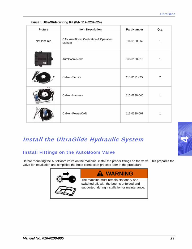
TABLE 4. UltraGlide Wiring Kit (P/N 117-0232-024)
Picture Item Description Part Number Qty.
Not Pictured CAN AutoBoom Calibration & Operation Manual 016-0130-062 1
AutoBoom Node 063-0130-013 1
Cable - Sensor 115-0171-527 2
Cable - Harness 115-0230-045 1
Cable - Power/CAN 115-0230-007 1
WARNINGThe machine must remain stationary and switched off, with the booms unfolded and supported, during installation or maintenance.

Chapter 4
30 CaseIH 3150/3185, Pre-2002 Tyler Patriot Open Center
Refer to the following table to install the fittings in the appropriate ports on the AutoBoom Valve.
Mount the AutoBoom Valve1. Secure the PowerGlide Plus AutoBoom valve (P/N 063-0131-116) to the mounting plate (P/N 107-0171-
619) using four 5/16” hex bolts (P/N 311-0049-235) and four 5/16” lock washers (P/N 313-1000-019).
FIGURE 1. AutoBoom Valve Mounted on the Valve Mounting Plate
2. Secure the mounting plate to the cross rail behind the sprayer’s tank using two 2-1/16” W x 3” L x 3/8” thread U-bolts (P/N 107-0171-609) and four 3/8” zinc flanged lock nuts (P/N 312-1001-164).
FIGURE 2. AutoBoom Valve Mounted on the Sprayer
Fitting Part Number Port
Fitting - 7/16” JIC (M) to 9/16” SAE O-Ring (M) Straight Adapter Fitting 333-0012-044 LV, RV
Fitting - 9/16” JIC (M) to 9/16” SAE O-Ring (M) Straight Adapter 333-0012-045 LC, RC
Fitting - 3/4” SAE O-Ring (M) to 9/16” JIC (M) .031 Orifice Straight Adapter 333-0012-230 RT CYL RTN, LF CYL RTN
Fitting - 9/16” JIC (F) to 7/16” JIC (M) Straight Adapter 333-0012-159 RT CYL RTN, LF CYL RTN
Fitting - 3/4” SAE O-Ring (M) to 3/4” JIC (M) Straight Adapter 333-0012-093 P, T, Bypass
4
Manual No. 016-0230-005 31
UltraGlide
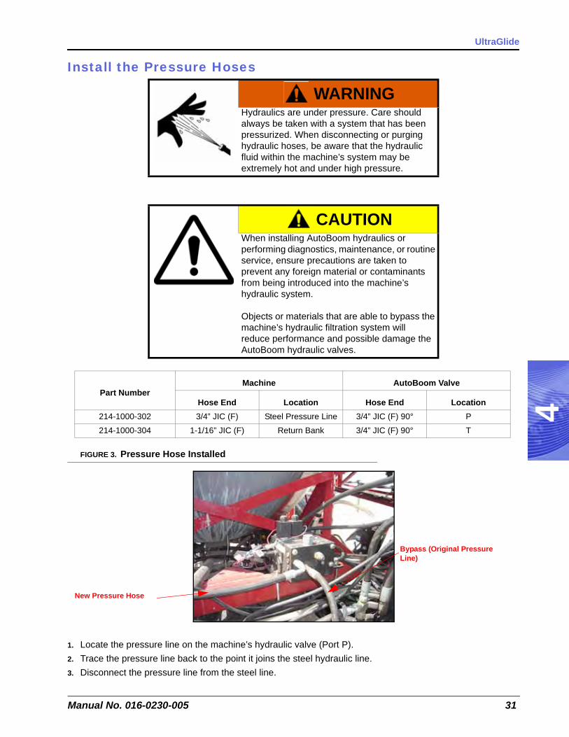
Install the Pressure Hoses
FIGURE 3. Pressure Hose Installed
1. Locate the pressure line on the machine’s hydraulic valve (Port P).2. Trace the pressure line back to the point it joins the steel hydraulic line.3. Disconnect the pressure line from the steel line.
WARNINGHydraulics are under pressure. Care should always be taken with a system that has been pressurized. When disconnecting or purging hydraulic hoses, be aware that the hydraulic fluid within the machine’s system may be extremely hot and under high pressure.
CAUTIONWhen installing AutoBoom hydraulics or performing diagnostics, maintenance, or routine service, ensure precautions are taken to prevent any foreign material or contaminants from being introduced into the machine’s hydraulic system.
Objects or materials that are able to bypass the machine’s hydraulic filtration system will reduce performance and possible damage the AutoBoom hydraulic valves.
Part NumberMachine AutoBoom Valve
Hose End Location Hose End Location214-1000-302 3/4” JIC (F) Steel Pressure Line 3/4” JIC (F) 90° P
214-1000-304 1-1/16” JIC (F) Return Bank 3/4” JIC (F) 90° T
New Pressure Hose
Bypass (Original Pressure Line)
Chapter 4
32 CaseIH 3150/3185, Pre-2002 Tyler Patriot Open Center
4. Connect the end of the pressure line to the Bypass Port on the AutoBoom valve.5. Connect the straight end of the supplied hydraulic hose (P/N 214-1000-302) to the machine’s steel line.6. Connect the 90° end of the installed hose to Port P on the AutoBoom valve.
Install the Tank Hoses - CaseIH and Patriot 1997 & Newer Only
FIGURE 4. Tank Hose Installed - CaseIH and Patriot 1997 & Newer Only
1. Disconnect the return hose from the machine’s hydraulic tank.2. Install the 1-1/16” JIC M/M/F swivel run tee (P/N 333-0012-109) on the machine’s hydraulic tank.3. Connect the return hose to the opposite end of the installed tee fitting.4. Install the 1-1/16” JIC M/F 90° swivel elbow fitting (P/N 333-0012-099) on the 90° end of the installed tee
fitting.5. Connect the straight end of the supplied hydraulic hose (P/N 214-1000-304) to the installed 90° elbow
fitting.6. Connect the 90° end of the hydraulic hose to Port T on the AutoBoom valve.
Install the Tank Hoses - Tyler Patriot 1996 & Older Only
FIGURE 5. Tank Hose Installed - Tyler Patriot Only
1. Locate the tank line on the machine’s hydraulic valve (Port T).

4
Manual No. 016-0230-005 33
UltraGlide
2. Trace the tank line back to the point it joins the steel hydraulic line.3. Disconnect the tank line from the steel line.4. Install the 3/4” JIC M/M/F swivel run tee (P/N 333-0012-039) on the machine’s steel hydraulic line.5. Connect the tank line to the opposite end of the installed tee fitting.6. Connect the straight end of the supplied hydraulic hose (P/N 214-1000-302) to the 90° end of the installed
tee fitting.7. Connect the 90° end of the hydraulic hose to Port T on the AutoBoom valve.
Install Left and Right Cylinder Hoses
1. Disconnect the cylinder hoses from the rod-end of the machine’s tilt cylinders.2. Route the right cylinder hose back to the AutoBoom valve and connect it to Port RV.3. Route the left cylinder hose back to the AutoBoom valve and connect it to Port LV on the AutoBoom valve.
FIGURE 6. Raise Hoses Installed on the Tilt Cylinder
4. Remove the fittings from the rod-end of the tilt cylinders.5. Install the 3/8” NPT (M) to 9/16” JIC (M) straight adapter fittings (P/N 333-0012-123) into the rod-end tilt
cylinder ports.6. Connect the straight end of the supplied hydraulic hose (P/N 214-1000-303) in the installed fitting in the rod-
end of the machine’s right tilt cylinder.7. Connect the 90° end of the hydraulic hose to Port RC on the AutoBoom valve.8. Connect the straight end of the supplied hydraulic hose (P/N 214-1000-303) in the installed fitting in the rod-
end of the machine’s left tilt cylinder.9. Connect the 90° end of the hydraulic hose to Port LC on the AutoBoom valve.
Part NumberMachine AutoBoom Valve
Hose End Location Hose End Location214-1000-303 9/16” JIC (F) Left Tilt Cylinder 3/4” JIC (F) 90° LC
214-1000-303 9/16” JIC (F) Right Tilt Cylinder 3/4” JIC (F) 90° RC

Chapter 4
34 CaseIH 3150/3185, Pre-2002 Tyler Patriot Open Center
Install the Down Hoses
FIGURE 7. Installed Down Hoses
1. Disconnect the hose from the base-end of the machine’s left tilt cylinder.2. Route the hose to the AutoBoom valve and connect it to the installed fitting in the RT CYL RTN Port.3. Disconnect the hose from the base-end of the machine’s right tilt cylinder.4. Route the hose to the AutoBoom valve and connect it to the installed fitting in the LF CYL RTN Port.
FIGURE 8. Installed Breathers
5. Remove the cylinder down fittings from the base-end of the tilt cylinders.6. Install two 9/16” SAE O-ring (M) to 3/8” NPT (F) straight adapter fittings (P/N 333-0012-197) in the base-end
of the tilt cylinders.7. Install the 3/8” NPT breather fittings (P/N 333-0012-196) into the installed adapters.
Installed Down Hoses
Installed Breather Fittings

4
Manual No. 016-0230-005 35
UltraGlide
UltraGlide Hydraulic Schematic

Chapter 4
36 CaseIH 3150/3185, Pre-2002 Tyler Patriot Open Center
Install the UltraGlide Sensors
Mount the UltraGlide Sensors
Sensor mounting locations may be influenced by the boom configuration. Determine the appropriate location for mounting sensors on the boom, ensuring the sensors will not interfere with or be damaged by folding or unfolding the booms. The sensor should be mounted outside of the boom fold, but inside of the boom breakaway.
Note: When mounting two sensors per boom, the inside sensor must be turned sideways to prevent the sensors from interfering when folding the booms.
FIGURE 9. Boom Sensor Mounting Locations
1. Place two 2-1/16” W x 3” L x 3/8” thread U-bolts (P/N 107-0171-609) on the outer-end of the center rail of the left boom.
2. Mount the left sensor (P/N 063-0130-014) on the installed U-bolts.3. Secure the sensor to the boom by installing four 3/8” zinc flanged lock nuts (P/N 312-1001-164) to the ends
of the U-bolts.4. Tighten the nuts to ensure the sensor is mounted securely.5. Repeat the steps above to mount the remaining boom sensor(s).
Outside Sensor Mounting Location
Optional Inside Sensor Mounting Location (Booms Folded)
4
Manual No. 016-0230-005 37
UltraGlide
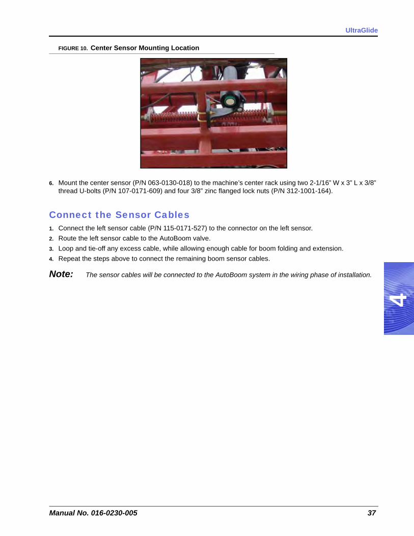
FIGURE 10. Center Sensor Mounting Location
6. Mount the center sensor (P/N 063-0130-018) to the machine’s center rack using two 2-1/16” W x 3” L x 3/8” thread U-bolts (P/N 107-0171-609) and four 3/8” zinc flanged lock nuts (P/N 312-1001-164).
Connect the Sensor Cables1. Connect the left sensor cable (P/N 115-0171-527) to the connector on the left sensor.2. Route the left sensor cable to the AutoBoom valve.3. Loop and tie-off any excess cable, while allowing enough cable for boom folding and extension.4. Repeat the steps above to connect the remaining boom sensor cables.
Note: The sensor cables will be connected to the AutoBoom system in the wiring phase of installation.

Chapter 4
38 CaseIH 3150/3185, Pre-2002 Tyler Patriot Open Center
Install the Gauge Wheels - Optional
Mount the Gauge Wheels
Note: Wheel mounting locations may be influenced by the boom configuration. Verify that the wheels will not interfere with or be damaged by folding or unfolding the booms.
Determine an appropriate location for mounting a wheel on the boom. The wheel should be mounted outside of the boom fold, but inside the boom breakaway.
FIGURE 11. Gauge Wheel Installed (Back View)
1. Remove the nuts from the right wheel axle (P/N 063-0131-589).2. Place the wheel (P/N 322-0131-008) on the right wheel axle.3. Reinstall the lug nuts on the wheel axle to secure the wheel.4. Attach the right wheel mounting bracket (P/N 116-0159-626) to the front of the right boom by installing three
2-1/16” W x 3” L x 3/8” thread U-bolts (P/N 107-0171-609) through the back of the mounting bracket and securing them with six 3/8” zinc flanged lock nuts (P/N 312-1001-164).
5. Insert the right wheel axle into the right wheel mounting bracket, positioning it so that the bottom of the wheel touches the ground (or nearly so).
6. Secure the gauge wheel assembly in the wheel mounting bracket by installing two 1/2”-13 x 1-1/2” SS hex bolts (P/N 311-0058-186) and two 1/2” zinc hex nuts (P/N 312-1001-043).
7. Repeat the steps above to install the left wheel.
WARNINGThe machine must remain stationary and switched off, with the booms unfolded and supported, while installation or maintenance is conducted.

4
Manual No. 016-0230-005 39
UltraGlide
Install the UltraGlide WiringWiring Connections
Note: For wiring connections made outside the cab, apply dielectric silicone grease (P/N 222-0000-006) generously on both the male and female ends of the connectors. Application of the grease will prevent corrosion to the pins and wires.
Install the AutoBoom Node
FIGURE 12. UltraGlide AutoBoom Node Installed
1. Mount the AutoBoom node (P/N 063-0130-013) to the cross beam of the machine’s center rack within a close proximity (3 feet/1 meter) to the AutoBoom valve.
Note: Position the node so that the cable connectors face down.
2. Insert the large, rectangular node connector on the harness cable (P/N 115-0230-045) into the left port of the AutoBoom node.
3. Tighten the bolt on the node connector to secure.
CAUTIONAlways connect the power cable as the last step in the wiring process and verify that the power leads are connected with the correct polarity. Reversing power leads can cause severe damage to the equipment.

Chapter 4
40 CaseIH 3150/3185, Pre-2002 Tyler Patriot Open Center
Connect the Harness to the Boom Function Controls
Complete the following steps to connect the harness to the machine’s boom function coils.
1. On the harness cable (P/N 115-0230-045), locate the Left Solenoid connector and connect it to Port 4A on the AutoBoom valve.
2. Connect the Right Solenoid connector to Port 4B on the AutoBoom valve.3. Connect the Left Prop connector to Port 5A on the AutoBoom valve.4. Connect the Right Prop connector to Port 13A on the AutoBoom valve.
FIGURE 13. Machine’s Left and Right Tilt Boom Function Coils
5. Locate the machine boom function coils near the machine’s boom stack valve.6. Disconnect the connector from the machine’s Left Tilt Up coil.7. Install a boom sense adapter cable (P/N 115-0171-558) between the coil and the machine’s coil connector.8. Connect boom sense adapter cables between the Left Tilt Down, Right Tilt Up, and Right Tilt Down coils
and the coil connectors.9. On the harness cable, locate the Left Solenoid Sense connectors. Isolate the connector labeled Up and
connect it to the Left Tilt Up coil via the installed boom sense adapter cable.10. Connect the Down Left Solenoid Sense connector to the Left Tilt Down coil via the installed boom sense
adapter cable.11. Connect the Right Solenoid Sense connectors to the machine’s Right Tilt Up and Right Tilt Down coils via
the installed boom sense adapter cables.

4
Manual No. 016-0230-005 41
UltraGlide
Install the Center Rack Control
FIGURE 14. Machine’s Center Boom Function Coils
1. Locate the Center Up coil on the machine’s stack valve.2. Unplug the coil connector from the Center Up coil.3. Install a center rack control boom sense adapter cable (P/N 115-0230-037) to the machine’s Up coil.4. Connect the coil connector to the installed boom sense adapter cable.5. Plug the single connectors on the installed boom sense adapter cable to the Center Up harness connectors
on the AutoBoom valve harness (P/N 115-0230-045).6. Locate the Center Down coil on the machine’s stack valve.7. Unplug the coil connector from the Center Down coil.8. Install a center rack control boom sense adapter cable (P/N 115-0230-037) to the machine’s Down coil.9. Connect the coil connector to the installed boom sense adapter cable.10. Plug the single connectors on the installed boom sense adapter cable in the Center Down harness
connectors on the AutoBoom valve harness (P/N 115-0230-045).
FIGURE 15. Machine’s Unloader Coil
11. Locate the Unloader coil on the machine’s stack valve.
Note: The appearance of the connectors may vary from machine to machine.
12. Unplug the Unloader coil and connect it to the female end of the AutoBoom weatherpack boom sense adapter cable (P/N 115-0171-558).
13. Connect the double-ended male end of the weatherpack boom sense adapter cable to the Unloader coil.14. Connect the single-ended male end of the weatherpack boom sense adapter cable to the female “open
center” connector on the AutoBoom valve harness.
Chapter 4
42 CaseIH 3150/3185, Pre-2002 Tyler Patriot Open Center
Connect the Harness Cable1. Route the harness cable (P/N 115-0230-045) toward the machine’s cab.2. Connect the harness cable to the controller cable (P/N 115-0230-007).3. Tighten the connector screw cap to secure the connection.
Note: Be sure to allow enough slack in the harness cable to allow for boom racking.
Connect the Controller (If Applicable)1. Route the controller cable (P/N 115-0230-007) into the right side of the machine’s cab.2. Locate the two controller connectors. Connect these connectors to the AutoBoom controller (P/N 063-0130-
011).
Note: The AutoBoom controller should be mounted in the machine’s cab so that the machine operator has easy access to it.
Connect the Computer (If Applicable)
Refer to the Installation & Operation Manual and the appropriate wiring schematic beginning on page 43 for installation and wiring instructions for your specific field computer.
Connect the Power Leads1. Locate the power cable that has the red and white power leads at one end.2. Disconnect the machine’s connectors from the battery terminals.3. Install the red power lead on the positive battery terminal and reinstall the machine’s battery connector.4. Install the white power lead on the negative battery terminal and reinstall the machine’s battery connector.

4
Manual No. 016-0230-005 43
UltraGlide
UltraGlide Wiring Schematics
AutoBoom Controller

Chapter 4
44 CaseIH 3150/3185, Pre-2002 Tyler Patriot Open Center
Envizio Plus

4
Manual No. 016-0230-005 45
UltraGlide
SCS 4000/5000

Chapter 4
46 CaseIH 3150/3185, Pre-2002 Tyler Patriot Open Center
Viper Pro & Envizio Pro

4
Manual No. 016-0230-005 47
UltraGlide

Chapter 4
48 CaseIH 3150/3185, Pre-2002 Tyler Patriot Open Center

CHAPTER
5
Manual No. 016-0230-005 49
Chapter 5Replacement Parts
This section contains replacement part diagrams and listings for PowerGlide Plus,and UltraGlide systems. Please refer to these diagrams when calling to request replacement parts.
Valve Blocks
PowerGlide Plus Valve Block Replacement Parts

Chapter 5
50 CaseIH 3150/3185, Pre-2002 Tyler Patriot Open Center
UltraGlide Valve Block Replacement Parts

5
Manual No. 016-0230-005 51
Replacement Parts
Wheel and Assembly Brackets
Machine-Specific Wheels and Brackets
Cushioned Axle

Chapter 5
52 CaseIH 3150/3185, Pre-2002 Tyler Patriot Open Center
Sensors and Brackets
Molded Sensor Replacement Parts
Machine-Specific Sensor U-Bolts
Index
Manual No. 016-0230-005 53
HHydraulic
Fittings 4Safety 2
IImportant Safety Information 1
Electrical Safety 2Hydraulic Safety 2
Introduction 3
KKit Contents
PowerGlide Plus 5
PPoint of Reference 4PowerGlide Plus 5
InstallGauge Wheels 16Hydraulic System 9
Down Hoses 14Fittings 9Left and Right Cylinder Hoses 13Mount the AutoBoom Valve 9PowerGlide Plus Hydraulic Schematic 15Pressure and Tank Hoses (CaseIH Only) 10Pressure and Tank Hoses (Tyler Patriot Only) 12
Wiring 17AutoBoom Node 17Connecting the Controller (if applicable) 19Connecting the Harness Cable 18Connecting the Harness to Boom Function
Controls 18Connecting the Power Leads 19PowerGlide Wiring Schematics
20Wiring Connections 17
Wiring ConnectionsComputer (if applicable) 19
Kit Contents 5Preparing for Installation 4
RRecommendations 4Replacement Parts
Machine-Specific Wheels and Brackets 51Sensors and Brackets 52
Machine-Specific Sensor U-Bolts 52Molded Sensor Replacement Parts 52
Valve Blocks 49PowerGlide Plus 49UltraGlide 50
WheelCushioned Axle 51
Wheel and Assembly Brackets 51
TTools Needed 4
UUltraGlide
InstallGauge Wheels (Optional) 38Hydraulic System 29
Down Hoses 34Fittings 29Left and Right Cylinder Hoses 33Mount the AutoBoom Valve 30Pressure Hoses 31Tank Hoses - CaseIH and Patriot 1997 and
Newer 32Tank Hoses - Patriot 1996 & Older 32UltraGlide Hydraulic Schematic 35
Sensors 36Connecting Sensors 37Mounting Sensors 36
Wiring 39AutoBoom Node 39Connecting Power Leads 42Connecting the Computer 42Connecting the Controller 42Connecting the Harness Cable 42Connecting the Harness to Boom Function
Controls 40Installing Center Rack Control 41UltraGlide Wiring Schematics 43
AutoBoom Controller 43Envizio Plus 44SCS 4000/5000 45Viper Pro & Envizio Pro 46
Wiring Connections 39

Index
54 CaseIH 3150/3185, Pre-2002 Tyler Patriot Open Center

Raven Industries will not assume any expense or liability for repairs made outside our facilities without written consent. Raven Industries is not responsible for damage to any associated equipment or products and will not be liable for loss of profit or other special damages. The obligation of this warranty is in lieu of all other warranties, expressed or implied, and no person or organization is
authorized to assume any liability for Raven Industries.
Damages caused by normal wear and tear, misuse, abuse, neglect, accident, or improper installation and maintenance are not covered
by this warranty.
What Does this Warranty Cover?
How Long is the Coverage Period?
How Can I Get Service?
What Will Raven Industries Do?
What is not Covered by this Warranty?
Bring the defective part and proof of purchase to your Raven Dealer.If your Dealer agrees with the warranty claim, the Dealer will send the part and proof of purchase to their distributor or to Raven Industries
for final approval.
Upon confirmation of the warranty claim, Raven Industries will, at our discretion, repair or replace the defective part and pay for return
freight.
RAVEN INDUSTRIESLimited Warranty
This warranty covers all defects in workmanship or materials in your Raven Applied Technology Product under normal use, maintenance,
and service.
Raven Applied Technology Products are covered by this warranty for 12 months after the date of purchase. This warranty coverage applies
only to the original owner and is nontransferable.

Notice: This document and the information provided are the property of Raven Industries, Inc. and may only be used as authorized by Raven Industries, Inc. All rights reserved under copyright laws.
CaseIH 3150/3185, Pre-2002 Tyler Patriot Open CenterAutoBoom™ Installation Manual(P/N 016-0230-005 Rev C 6/09)
Raven Industries Toll Free (U.S. and Canada): (800)-243-5435Applied Technology Division or Outside the U.S. :1 605-575-0722P.O. Box 5107 Fax: 605-331-0426Sioux Falls, SD 57117-5107 www.ravenprecision.com


