EFFECTIVE SERIAL NO. 370400-076-DW-5-93 OWNERS MANUAL ECONOTON II / IIR REVISION 2/2000 PART NO. 999938 SERIAL NO. __________________________ AUTO CRANE COMPANY PO BOX 580697, TULSA, OK 74158-0697 4707 N. MINGO ROAD, TULSA, OK 74117 PHONE (918) 836-0463 FAX (918) 834-5979
Transcript
EFFECTIVE SERIAL NO. 370400-076-DW-5-93
OWNERS MANUALECONOTON II / IIR
REVISION 2/2000
PART NO. 999938
SERIAL NO. __________________________
AUTO CRANE COMPANYPO BOX 580697, TULSA, OK 74158-0697
4707 N. MINGO ROAD, TULSA, OK 74117
PHONE (918) 836-0463
FAX (918) 834-5979
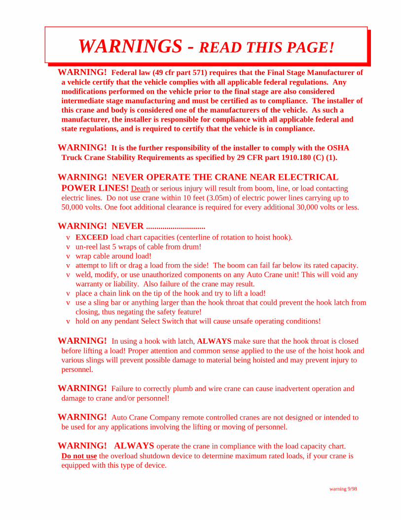
WARNING! Federal law (49 cfr part 571) requires that the Final Stage Manufacturer ofa vehicle certify that the vehicle complies with all applicable federal regulations. Anymodifications performed on the vehicle prior to the final stage are also consideredintermediate stage manufacturing and must be certified as to compliance. The installer ofthis crane and body is considered one of the manufacturers of the vehicle. As such amanufacturer, the installer is responsible for compliance with all applicable federal andstate regulations, and is required to certify that the vehicle is in compliance.
WARNING! It is the further responsibility of the installer to comply with the OSHATruck Crane Stability Requirements as specified by 29 CFR part 1910.180 (C) (1).
WARNING! NEVER OPERATE THE CRANE NEAR ELECTRICALPOWER LINES! Death or serious injury will result from boom, line, or load contactingelectric lines. Do not use crane within 10 feet (3.05m) of electric power lines carrying up to50,000 volts. One foot additional clearance is required for every additional 30,000 volts or less.
WARNING! NEVER .............................v EXCEED load chart capacities (centerline of rotation to hoist hook).v un-reel last 5 wraps of cable from drum!v wrap cable around load!v attempt to lift or drag a load from the side! The boom can fail far below its rated capacity.v weld, modify, or use unauthorized components on any Auto Crane unit! This will void any
warranty or liability. Also failure of the crane may result.v place a chain link on the tip of the hook and try to lift a load!v use a sling bar or anything larger than the hook throat that could prevent the hook latch from
closing, thus negating the safety feature!v hold on any pendant Select Switch that will cause unsafe operating conditions!
WARNING! In using a hook with latch, ALWAYS make sure that the hook throat is closedbefore lifting a load! Proper attention and common sense applied to the use of the hoist hook andvarious slings will prevent possible damage to material being hoisted and may prevent injury topersonnel.
WARNING! Failure to correctly plumb and wire crane can cause inadvertent operation anddamage to crane and/or personnel!
WARNING! Auto Crane Company remote controlled cranes are not designed or intended tobe used for any applications involving the lifting or moving of personnel.
WARNING! ALWAYS operate the crane in compliance with the load capacity chart. Do not use the overload shutdown device to determine maximum rated loads, if your crane isequipped with this type of device.
Auto Crane products are designed to provide manyyears of safe, trouble-free, dependable service when properlyused and maintained.
To assist you in obtaining the best service from yourcrane and to avoid untimely crane and/or vehicle failure, thismanual provides the following operating and serviceinstructions. It is specifically recommended that alloperating and service personnel consider this manual asmandatory material for reading and study before operating orservicing Auto crane products. It is highly recommendedthat crane owners, equipment managers and supervisors alsoread this manual.
Auto Crane has incorporated several safety features inthe Econo-Ton II series for your protection. The material andelectrical systems were designed to minimize weight andlengthen durability.
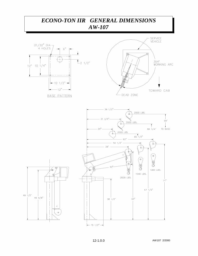
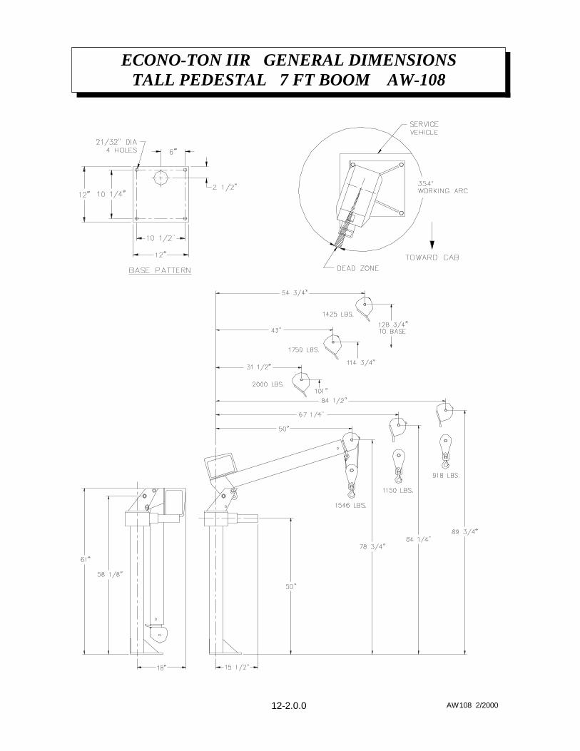
For your convenience the overall dimensions of theEcono-Ton II series crane are on the General DimensionDrawing. Maximum turning radius is shown on the drawingas a distance from the center line of the crane rotation to theoutside edge of the winch and on the power rotation model,the outside edge of the rotation motor .
Remember, the crane adds weight to the vehicle.Adding weight may change the driving and ridingcharacteristics of the vehicle unless the appropriate overloadspring(s) are installed on the truck. The payload of thevehicle is reduced by the weight of the crane. The operatorshould exercise care when loading the vehicle. Distributingthe payload on the vehicle evenly will greatly improve thedriving and riding characteristics of the vehicle.
The Econo-Ton II series cranes are attached directly toyour 12 volt truck electrical system. The power cable andretaining clips are included with the crane. A typical powercable mounting and hookup is shown on page 2-3.0.0. Theperformance of your new crane depends on the truck electricalsystem. The use of the low maintenance battery is notrecommended for use on any Auto Crane product. Therecommended alternator and battery that will give the longestlife with the most useful duty cycle is a 60 amp. alternatorwith a 120 minute reserve capacity, deep cycle battery. Thesespecifications should be considered minimum.
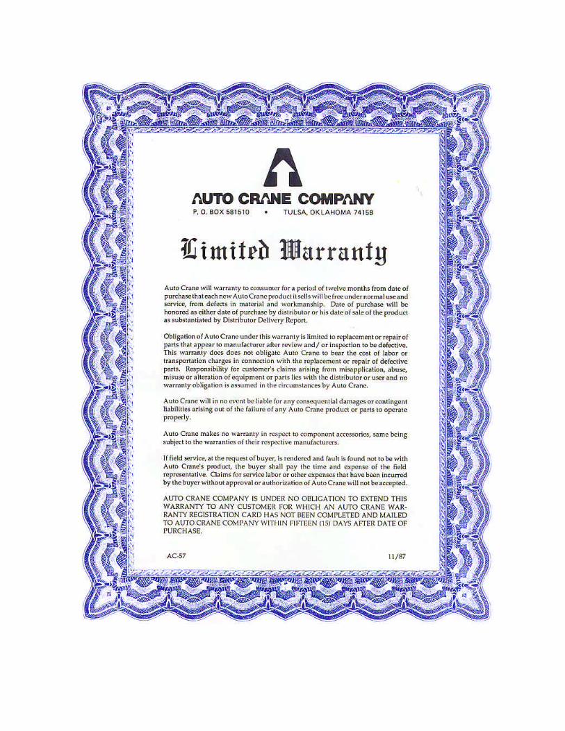
Auto Crane Company issues a limitedwarranty certificate with each unit sold.See last page for warranty policy.
It has always been Auto Crane Company policy tohandle all warranty claims we receive as promptly as
possible. If a warranty claim involves discrepant material orworkmanship, Auto Crane will take immediate correctiveaction. It is understandable that Auto Crane company cannotassume responsibility of liability when it is obvious that ourproducts have been abused, mis-used, overloaded orotherwise damaged by inexperienced persons trying tooperate the equipment without reading the manual.
Auto Crane will not assume responsibility orliability for any modifications or changes made tounit, or installation of component parts done withoutauthorization.
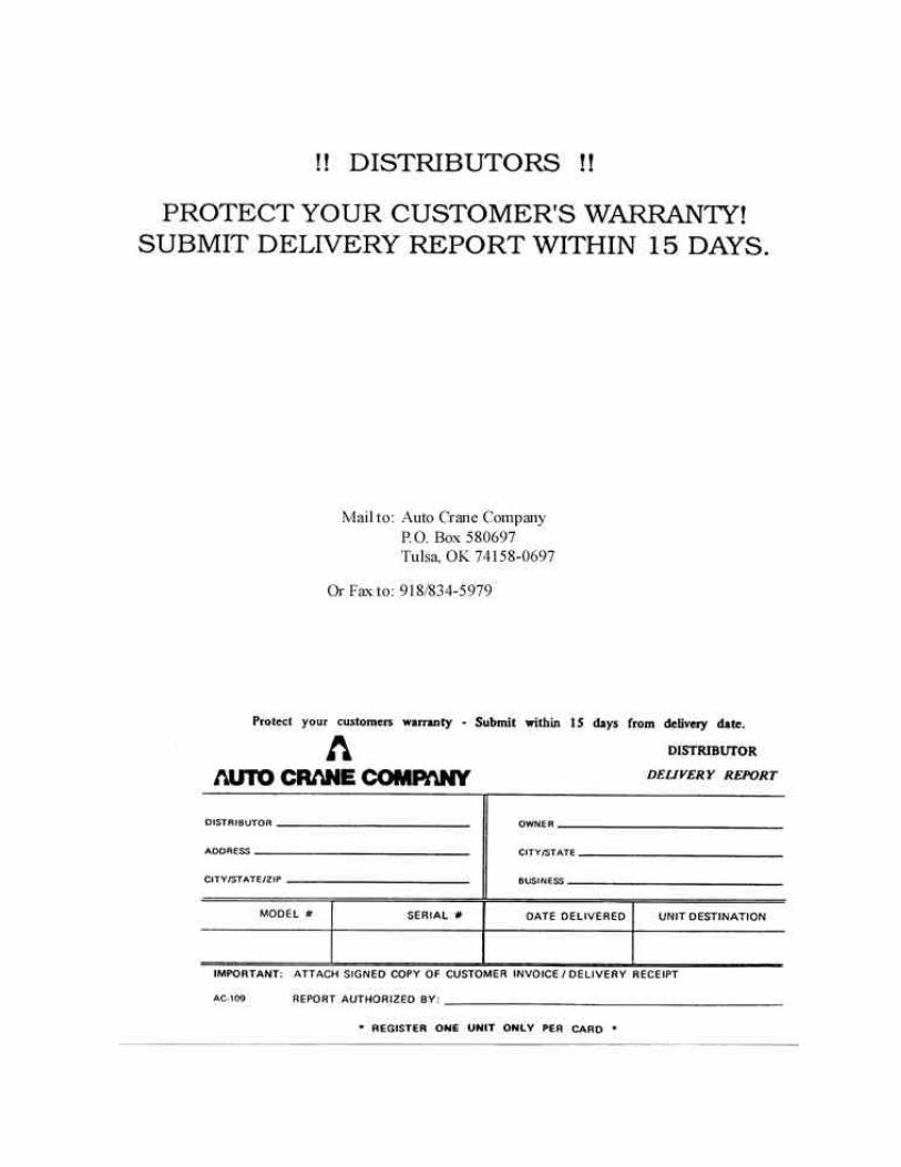
Auto Crane maintains a strong distributor network and aknowledgeable Customer Service Department. In most cases,an equipment problem is solved via phone conversation withour customer service department. The customer servicedepartment also has the ability to bring a local distributor, aregional sales manager, or a factory serviceman into thesolution of an equipment problem. If, through no fault ofAuto crane company, it is necessary to send an experiencedfactory serviceman on a field service call, the rates stated inthe Auto Crane Distributor's Flat Rate Manual will apply.
Auto Crane Company's extensive Research andDevelopment Program allow our customers to use the bestequipment on the market. Our Engineering Staff and ourknowledgeable sales people, are always available to ourcustomers in solving crane and winch-type applicationproblems. When in doubt, call the Auto Crane factory.
DISTRIBUTOR ASSISTANCE:Should you require any assistance not given in this
manual, we recommend that you consult your nearest AutoCrane Distributor. Our distributors sell authorized parts andhave service departments that can solve almost any neededrepair.
NOTE: THIS MANUAL SHOULD
REMAIN WITH THE CRANE AT ALLTIMES.
This manual does not cover all maintenance, operating,or repair instructions pertinent to all possible situations. Ifyou require additional information, please contact the AutoCrane Company at the following telephone number: (918)836-0463. The information contained in the manual is ineffect at the time of this printing. Auto Crane Companyreserves the right to update this material without notice orobligation.
TON2NTRO 2/2000
INTRODUCTIONECONO-TON II / II R
1-1.0.0
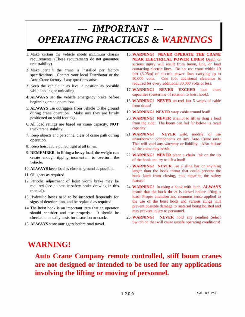
1. Make certain the vehicle meets minimum chassisrequirements. (These requirements do not guaranteeunit stability)
2. Make certain the crane is installed per factoryspecifications. Contact your local Distributor or theAuto Crane factory if any questions arise.
3. Keep the vehicle in as level a position as possiblewhile loading or unloading.
4. ALWAYS set the vehicle emergency brake beforebeginning crane operations.
5. ALWAYS use outriggers from vehicle to the groundduring crane operation. Make sure they are firmlypositioned on solid footings.
6. All load ratings are based on crane capacity, NOTtruck/crane stability.
7. Keep objects and personnel clear of crane path duringoperation.
8. Keep hoist cable pulled tight at all times.
9. REMEMBER, in lifting a heavy load, the weight cancreate enough tipping momentum to overturn thevehicle.
10. ALWAYS keep load as close to ground as possible.
11. Oil gears as required.
12. Periodic adjustment of hoist worm brake may berequired (see automatic safety brake drawing in thismanual).
13. Hydraulic hoses need to be inspected frequently forsigns of deterioration, and be replaced as required.
14. The hoist hook is an important item that an operatorshould consider and use properly. It should bechecked on a daily basis for distortion or cracks.
15. ALWAYS store outriggers before road travel.
16. WARNING! NEVER OPERATE THE CRANENEAR ELECTRICAL POWER LINES! Death orserious injury will result from boom, line, or loadcontacting electric lines. Do not use crane within 10feet (3.05m) of electric power lines carrying up to50,000 volts. One foot additional clearance isrequired for every additional 30,000 volts or less.
17. WARNING! NEVER EXCEED load chartcapacities (centerline of rotation to hoist hook).
18. WARNING! NEVER un-reel last 5 wraps of cablefrom drum!
19. WARNING! NEVER wrap cable around load!
20. WARNING! NEVER attempt to lift or drag a loadfrom the side! The boom can fail far below its ratedcapacity.
21. WARNING! NEVER weld, modify, or useunauthorized components on any Auto Crane unit!This will void any warranty or liability. Also failureof the crane may result.
22. WARNING! NEVER place a chain link on the tipof the hook and try to lift a load!
23. WARNING! NEVER use a sling bar or anythinglarger than the hook throat that could prevent thehook latch from closing, thus negating the safetyfeature!
24. WARNING! In using a hook with latch, ALWAYSinsure that the hook throat is closed before lifting aload! Proper attention and common sense applied tothe use of the hoist hook and various slings willprevent possible damage to material being hoisted andmay prevent injury to personnel.
25. WARNING! NEVER hold any pendant SelectSwitch on that will cause unsafe operating conditions!
--- IMPORTANT --- OPERATING PRACTICES & WARNINGS
WARNING!Auto Crane Company remote controlled, stiff boom cranesare not designed or intended to be used for any applicationsinvolving the lifting or moving of personnel.
1-2.0.0 SAFTIPS 2/98
26. Make sure this manual has been thoroughly read byall crane operating personnel and supervisors.
27. A routine inspection of the crane should be mandatorybefore each operating day. Any defects should becorrected immediately.
28. At a job site the vehicle should be positioned so thatthe crane can adequately reach the load within therated capacity (centerline of rotation to hoist hook).
29. Keep the vehicle as level as possible during operation.
30. For electric cranes, engage emergency brake andleave ignition on with transmission in neutral (or inpark for automatic transmissions). Activate any cranepower switches. For Auto Crane units requiringbattery and hydraulic operation, engage emergencybrake, place gear selector in neutral, press clutch,activate PTO, release clutch and after hydraulic fluidis warm, set throttle control to proper engine speed.
31. Always use outriggers from the truck to the ground.Be sure these are firm and adequately positioned.When rotating, keep load as low to the ground aspossible.
32. Remove pendant control from cab or storage area. Onsmaller units, plug pendant into receptacle on crane.On larger units, remove pendant control from guardand unwrap cable from boom. Do not operate craneuntil cable is unwound completely. On all cranes,detach hook from dead man. Crane is now ready foroperation.
33. Always boom up before rotating so the boom willclear the required boom support.
34. When extending the boom, always maintain clearancebetween the boom crown and the traveling block orhoist hook.
35. Always observe safe and practical operation to avoidpossible accidents. Refer to Safety Tips andPrecautions.
36. After completing lifting operations, return the boomto stowed position on the boom support. Avoidunneeded pressure on the boom support.
37. Store pendant control on proper location (in cab or oncrane).
38. Return outriggers to stowed position. Make sure theyare pinned in place or jacklegs are returned tocompartment.
39. Check work area for any tools or equipment notstored.
40. Release throttle control, depress clutch and disengagePTO. Deactivate any crane power switches.
41. Report any unusual occurrence during crane operationthat may indicate required maintenance or repair.
42. NEVER use two cranes to support a load too large foreither crane.
43. Spray all electrical equipment with special corrosionresistant coating. This eliminates rust or corrosiondue to melting and freezing action of condensation.
1-3.0.0OPER 2/98
--- IMPORTANT --- OPERATION OF UNIT
OPERATION OF OUTRIGGERS
For hydraulic outriggers:1. Shift crane/outrigger control valve to "outrigger"
position.2. While operating the outrigger control valves
(located on the outrigger cylinders)simultaneously operate the boom-up controlswitch. This will allow the hydraulic system tobuild pressure.
3. After outriggers are positioned, returncrane/outrigger selector to "crane" position.
4. Crane is now ready to operate.
For manual outriggers:1. Pull lock pins to release jack leg or drop down
outrigger and move to outermost lock position.2. Make sure lock pins are reinstalled properly.3. Lower outrigger pad to firm ground and adjust
foot to take out slack.4. Crane is now ready to operate.
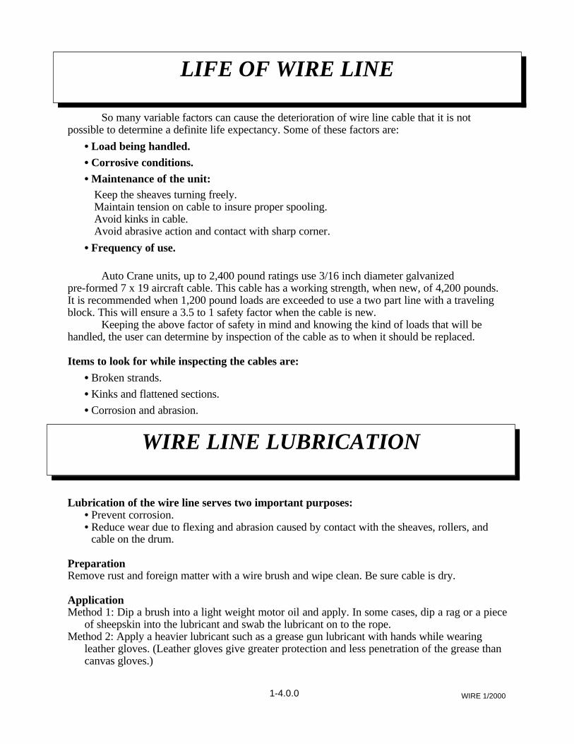
So many variable factors can cause the deterioration of wire line cable that it is notpossible to determine a definite life expectancy. Some of these factors are:
• Load being handled.
• Corrosive conditions.
• Maintenance of the unit: Keep the sheaves turning freely. Maintain tension on cable to insure proper spooling. Avoid kinks in cable. Avoid abrasive action and contact with sharp corner.
• Frequency of use.
Auto Crane units, up to 2,400 pound ratings use 3/16 inch diameter galvanizedpre-formed 7 x 19 aircraft cable. This cable has a working strength, when new, of 4,200 pounds.It is recommended when 1,200 pound loads are exceeded to use a two part line with a travelingblock. This will ensure a 3.5 to 1 safety factor when the cable is new.
Keeping the above factor of safety in mind and knowing the kind of loads that will behandled, the user can determine by inspection of the cable as to when it should be replaced.
Items to look for while inspecting the cables are:
• Broken strands.• Kinks and flattened sections.• Corrosion and abrasion.
Lubrication of the wire line serves two important purposes: • Prevent corrosion. • Reduce wear due to flexing and abrasion caused by contact with the sheaves, rollers, and
cable on the drum.
PreparationRemove rust and foreign matter with a wire brush and wipe clean. Be sure cable is dry.
ApplicationMethod 1: Dip a brush into a light weight motor oil and apply. In some cases, dip a rag or a piece
of sheepskin into the lubricant and swab the lubricant on to the rope.Method 2: Apply a heavier lubricant such as a grease gun lubricant with hands while wearing
leather gloves. (Leather gloves give greater protection and less penetration of the grease thancanvas gloves.)
1-4.0.0 WIRE 1/2000
LIFE OF WIRE LINE
WIRE LINE LUBRICATION
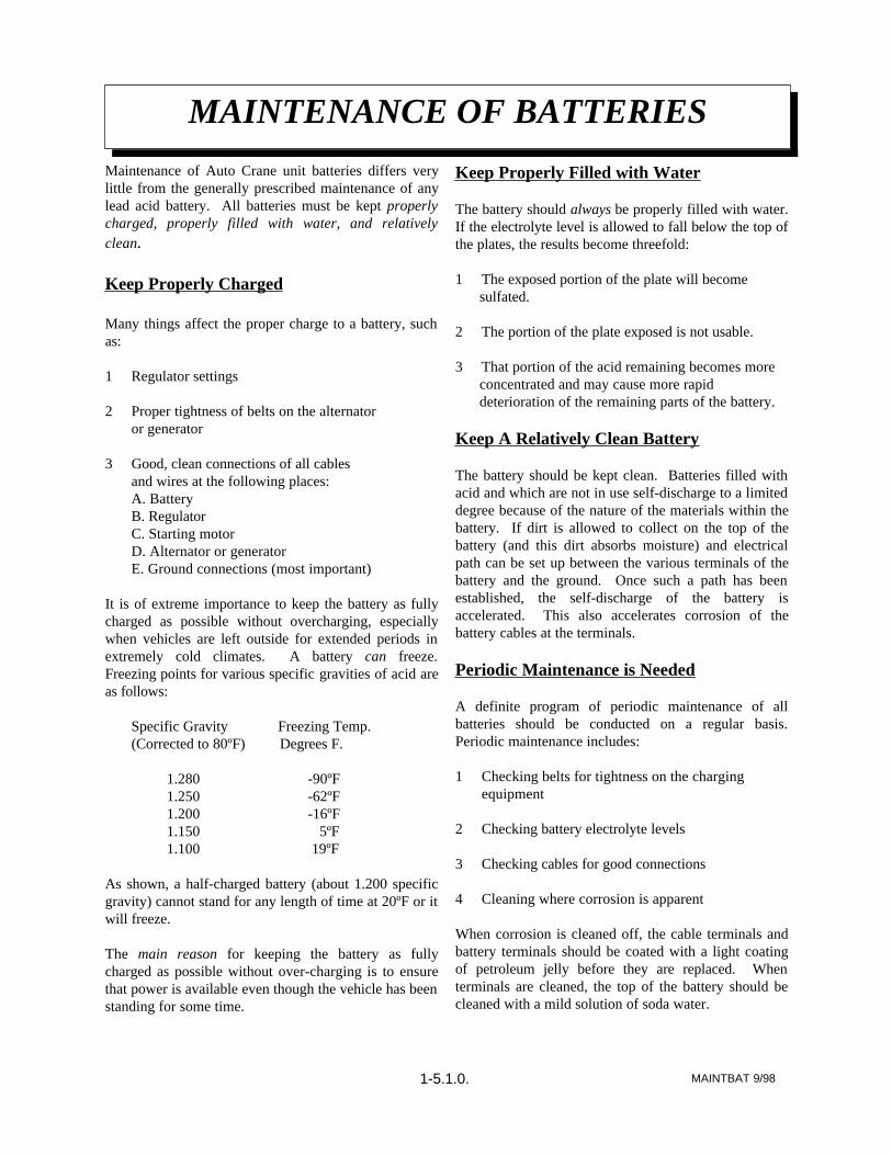
Maintenance of Auto Crane unit batteries differs verylittle from the generally prescribed maintenance of anylead acid battery. All batteries must be kept properlycharged, properly filled with water, and relativelyclean.
Keep Properly Charged
Many things affect the proper charge to a battery, suchas:
1 Regulator settings
2 Proper tightness of belts on the alternator or generator
3 Good, clean connections of all cablesand wires at the following places:A. BatteryB. RegulatorC. Starting motorD. Alternator or generatorE. Ground connections (most important)
It is of extreme importance to keep the battery as fullycharged as possible without overcharging, especiallywhen vehicles are left outside for extended periods inextremely cold climates. A battery can freeze.Freezing points for various specific gravities of acid areas follows:
Specific Gravity Freezing Temp.(Corrected to 80ºF) Degrees F.
As shown, a half-charged battery (about 1.200 specificgravity) cannot stand for any length of time at 20ºF or itwill freeze. The main reason for keeping the battery as fullycharged as possible without over-charging is to ensurethat power is available even though the vehicle has beenstanding for some time.
Keep Properly Filled with Water
The battery should always be properly filled with water.If the electrolyte level is allowed to fall below the top ofthe plates, the results become threefold:
1 The exposed portion of the plate will becomesulfated.
2 The portion of the plate exposed is not usable.
3 That portion of the acid remaining becomes moreconcentrated and may cause more rapiddeterioration of the remaining parts of the battery.
Keep A Relatively Clean Battery
The battery should be kept clean. Batteries filled withacid and which are not in use self-discharge to a limiteddegree because of the nature of the materials within thebattery. If dirt is allowed to collect on the top of thebattery (and this dirt absorbs moisture) and electricalpath can be set up between the various terminals of thebattery and the ground. Once such a path has beenestablished, the self-discharge of the battery isaccelerated. This also accelerates corrosion of thebattery cables at the terminals.
Periodic Maintenance is Needed
A definite program of periodic maintenance of allbatteries should be conducted on a regular basis.Periodic maintenance includes:
1 Checking belts for tightness on the chargingequipment
2 Checking battery electrolyte levels
3 Checking cables for good connections
4 Cleaning where corrosion is apparent
When corrosion is cleaned off, the cable terminals andbattery terminals should be coated with a light coatingof petroleum jelly before they are replaced. Whenterminals are cleaned, the top of the battery should becleaned with a mild solution of soda water.
MAINTBAT 9/98
MAINTENANCE OF BATTERIES
1-5.1.0.
Low Maintenance Batteries(Maintenance Free)
Low maintenance batteries should not be used onAuto Cranes or trucks equipped with Auto Cranes.The batteries are not designed for "deep" discharge.
Testing Your Battery
If the condition of the battery is in question, it should beremoved from the vehicle, taken to the shop, andallowed to reach room temperature. It should then berecharged until specific gravity readings taken atone-half hour intervals. If the specific gravity readingsare fairly uniform, the battery should be checked with ahigh rate tester. Use the tester in accordance with themanufacturer's instructions. The high rate tester is thebest method to test a questionable battery.
If, after charging, it is noted that the specific gravityreading of one cell is 30 points less than any of theother cells, it may be assumed that the cell is bad andthat the battery should be replaced. If all cells areuniform but not up to full charge, a low rate of charge
should be attempted for an extended time. This usuallywill recover a badly sulfated battery.
Replacing a Battery
If it is necessary to replace a battery, and a dry chargebattery is used, the following procedure applies:
1 Fill the battery with electrolyte of the properspecific gravity.
2 Place the battery on charge according to themanufacturer's instructions.
It is essential that the second step above be followed toensure that the battery going on the vehicle is fullycharged.
It is also very important that the battery hold-downs bechecked periodically to ensure that the batteries areproperly positioned to avoid vibration problems,breakage of cables or terminals. Care must be taken toavoid cracking or breaking containers or covers bytightening hold-down fixtures excessively. They alsomust not be so loose that breakage results from ahold-down that is too loose.
MAINTBAT 9/98
MAINTENANCE OF BATTERIES
1-5.2.0.
SafetyDecal 2/2000
SAFETY DECAL SECTION
ECONO-TON II
2-1.0.0
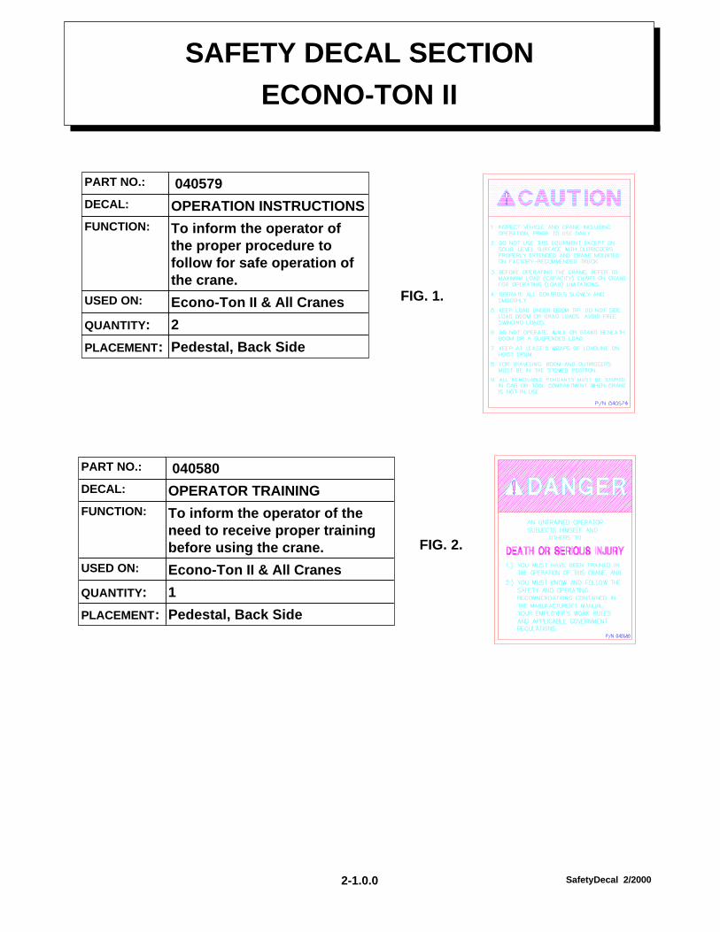
Pedestal, Back SidePLACEMENT:
2QUANTITY:
Econo-Ton II & All CranesUSED ON:
To inform the operator ofthe proper procedure tofollow for safe operation ofthe crane.
FUNCTION:
OPERATION INSTRUCTIONSDECAL:
040579PART NO.:
FIG. 1.
Pedestal, Back SidePLACEMENT:
1QUANTITY:
Econo-Ton II & All CranesUSED ON:
To inform the operator of theneed to receive proper trainingbefore using the crane.
FUNCTION:
OPERATOR TRAININGDECAL:
040580PART NO.:
FIG. 2.
SafetyDecal 2/2000
SAFETY DECAL SECTION
ECONO-TON II
Back of PedestalPLACEMENT:
1QUANTITY:
Econo-Ton II 110 Volt ACUSED ON:
To warn operator of possibleshock hazzard if the unit is notinstalled and operated properly.
FUNCTION:
WARNING 110 V.A.C.DECAL:
370125PART NO.:
Side of Traveling BlockPLACEMENT:
2QUANTITY:
Econo-Ton II & All cranes USED ON:
To inform the operator ofthe hazzard of proximity orcontact with the crane loadduring operation.
FUNCTION:
STAY CLEAR OF LOADDECAL:
040630PART NO.:
FIG. 3.
FIG. 4.
2-1.0.1
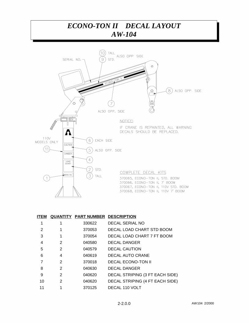
ECONO-TON II DECAL LAYOUTAW-104
2-2.0.0 AW104 2/2000
DECAL 110 VOLT370125111
DECAL STRIPING (4 FT EACH SIDE)040620210
DECAL STRIPING (3 FT EACH SIDE)04062029
DECAL DANGER04063028
DECAL ECONO-TON II37001827
DECAL AUTO CRANE04061946
DECAL CAUTION04057925
DECAL DANGER04058024
DECAL LOAD CHART 7 FT BOOM37005413
DECAL LOAD CHART STD BOOM37005312
DECAL SERIAL NO33062211
DESCRIPTIONPART NUMBERQUANTITYITEM
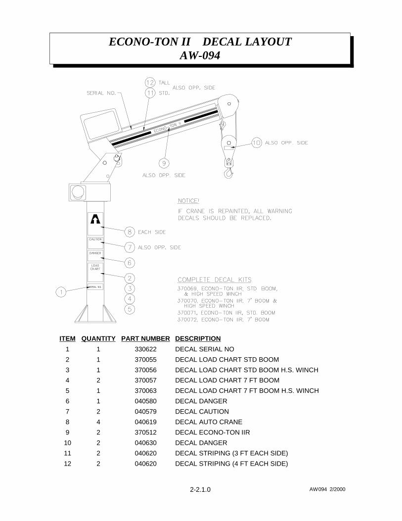
ECONO-TON II DECAL LAYOUTAW-094
2-2.1.0 AW094 2/2000
DECAL STRIPING (4 FT EACH SIDE)040620212
DECAL STRIPING (3 FT EACH SIDE)040620211
DECAL DANGER040630210
DECAL ECONO-TON IIR37051229
DECAL AUTO CRANE04061948
DECAL CAUTION04057927
DECAL DANGER04058016
DECAL LOAD CHART 7 FT BOOM H.S. WINCH37006315
DECAL LOAD CHART 7 FT BOOM37005724
DECAL LOAD CHART STD BOOM H.S. WINCH37005613
DECAL LOAD CHART STD BOOM37005512
DECAL SERIAL NO33062211
DESCRIPTIONPART NUMBERQUANTITYITEM
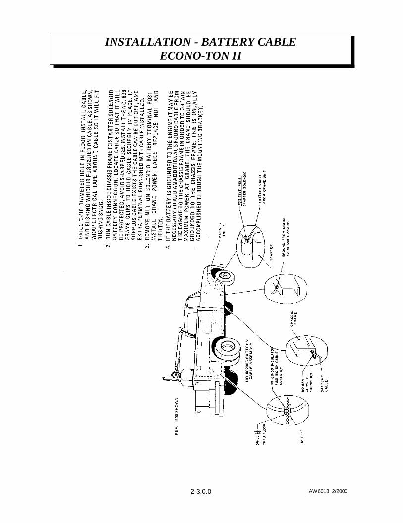
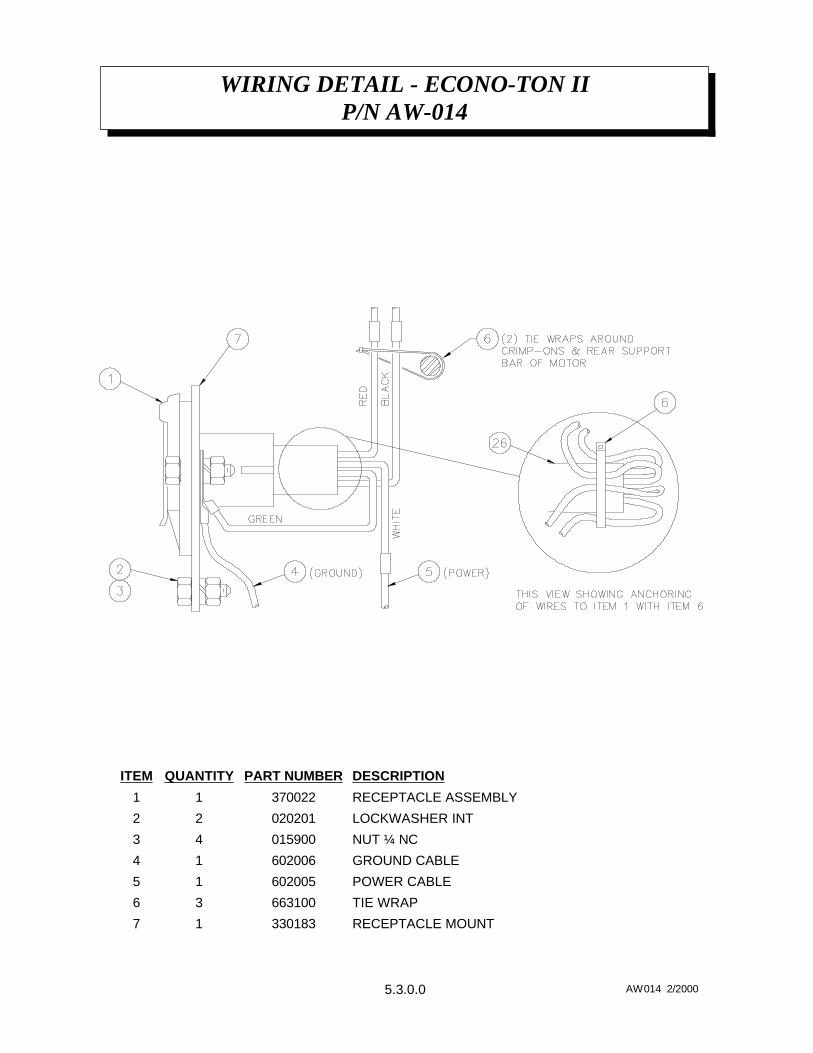
INSTALLATION - BATTERY CABLEECONO-TON II
2-3.0.0 AW6018 2/2000
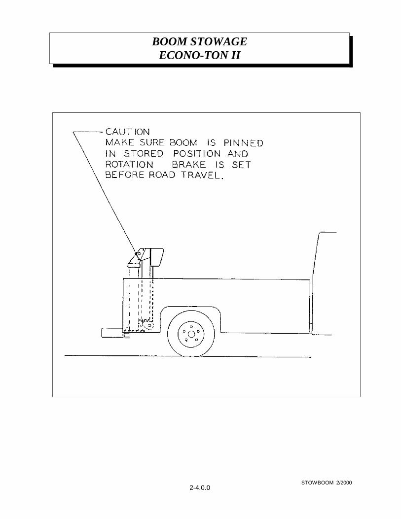
BOOM STOWAGEECONO-TON II
2-4.0.0STOWBOOM 2/2000
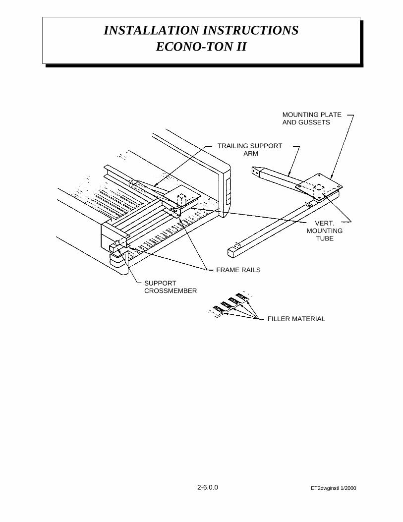
The Econo-Ton II cranes are shipped inone major assembly. The following is asuggested method for installation of theEcono-Ton II crane:
1 Remove the crane from the packingcrate and locate on the truck bed in thedesired position, checking for properclearance.
2 If the floor is made of wood, it may bedesirable to install a 3/8" plate approxi-mately six to eight inches larger thanthe base plate on top of the woodendeck. If the floor is heavy metal andribbed, no metal plate will be requiredunder the crane base plate. Fillersshould be installed to level the ribbedfloor if required. The crane may now beplaced in position and the base platemay be used as a template to drill themounting holes through the truck bedand additional plates if used. Refer toPages 2-6.0.0 and 2-7.0.0 for a typicalinstallation.
3 Each truck has its own unique mountingdifficulties. The mount and additionalbracing should be constructed so thecombined crane load of 6500 ft lbs anda vertical load of 2000 lbs will bedirected over the largest area possible.Install a brace which crosses bothframe rails and is bolted to the frame asshown in the drawing. This brace maybe square tubing and should extend out
to both sides of the truck and may beused as pocket for an outrigger, stabi-lizer, or jack leg holder. Add othersstructural members as required, includ-ing the back-up assembly which hasbeen pre-drilled to match the cranemounting holes. Bolt the crane in place.
4 Route the long cable (power cable)under the truck and to the positive poleon the starter solenoid. Tie the powercables with insulated straps to the truckframe and other members as required.Avoid the area of the exhaust systemwhen routing the cable.
5 Pin boom in working position.
6 Attach the removable pendant controlcable and test the crane for powerfunctions.
7 With jack legs or outriggers installed,pick up a load of 2000 pounds andmanually rotate this load approximately180° to insure that the crane is suffi-ciently supported and correctlyinstalled. Further reinforcement of thetruck bed may be added if required.
8 Store boom during travel. See page2-4.0.0 for illustration.
9 ALWAYS remove pendant whentraveling.
ASSEMBLY & INSTALLATION INSTRUCTIONS ECONO-TON II SERIES
ET3instl 2/20002-5.0.0
ET2dwginstl 1/20002-6.0.0
INSTALLATION INSTRUCTIONSECONO-TON II
SUPPORTCROSSMEMBER
FRAME RAILS
TRAILING SUPPORT ARM
MOUNTING PLATEAND GUSSETS
VERT.MOUNTING
TUBE
FILLER MATERIAL
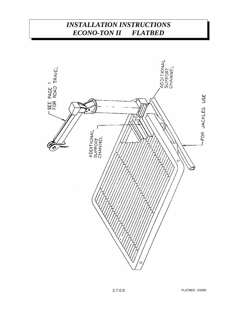
INSTALLATION INSTRUCTIONSECONO-TON II FLATBED
2-7.0.0 FLATBED 2/2000
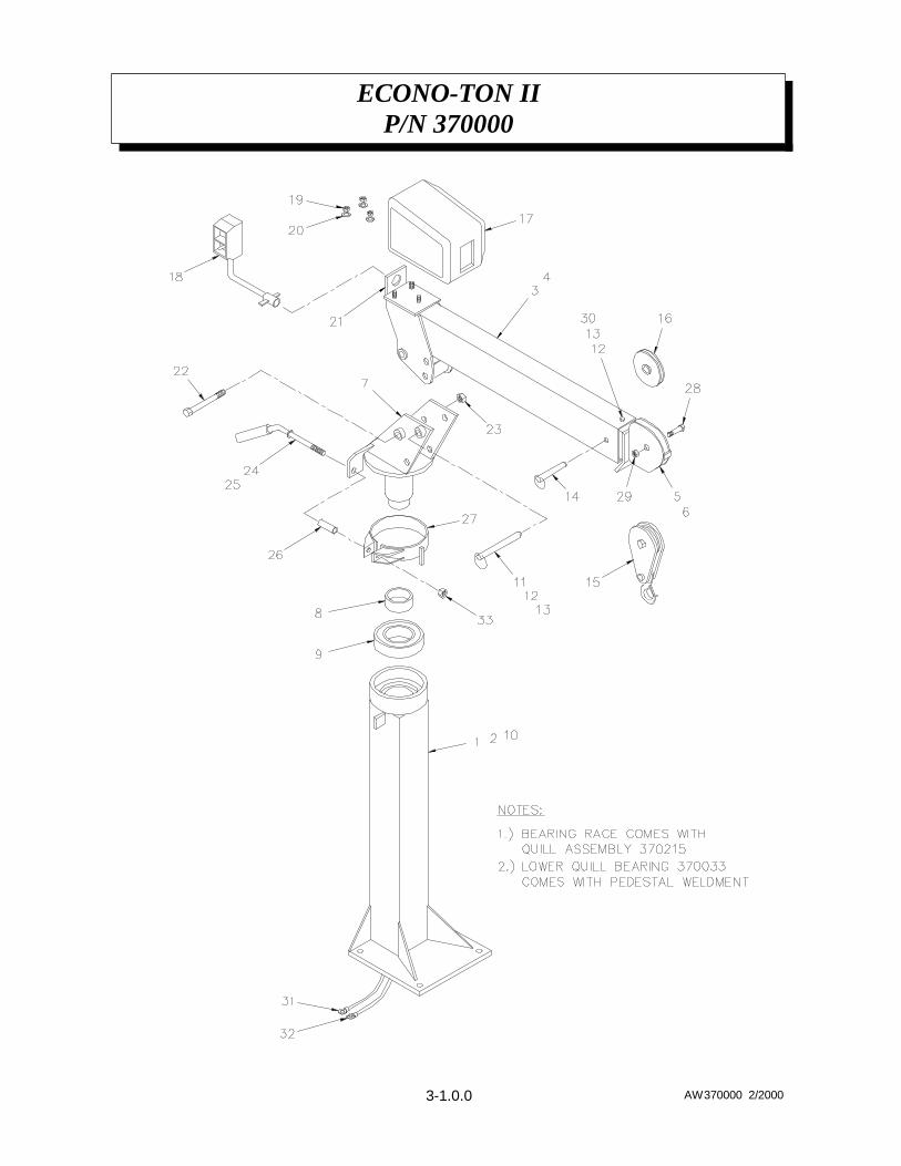
ECONO-TON IIP/N 370000
3-1.0.0 AW370000 2/2000
ECONO-TON II P/N 370000
P/N 370000
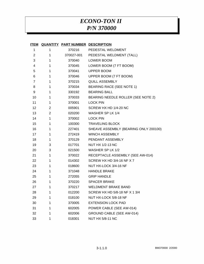
3-1.1.0 BM370000 2/2000
NUT HX 5/8-11 NC018301133
GROUND CABLE (SEE AW-014)602006132
POWER CABLE (SEE AW-014)602005131
EXTENSION LOCK PAD370005130
NUT HX-LOCK 5/8-18 NF018100129
SCREW HX HD 5/8-18 NF X 1 3/4012200128
WELDMENT BRAKE BAND370217127
SPACER BRAKE370220126
GRIP HANDLE272055125
HANDLE BRAKE371048124
NUT HX-LOCK 3/4-16 NF018600123
SCREW HX HD 3/4-16 NF X 7014302122
RECEPTACLE ASSEMBLY (SEE AW-014)370022121
WASHER SP LK 1/2021500320
NUT HX 1/2-13 NC017701319
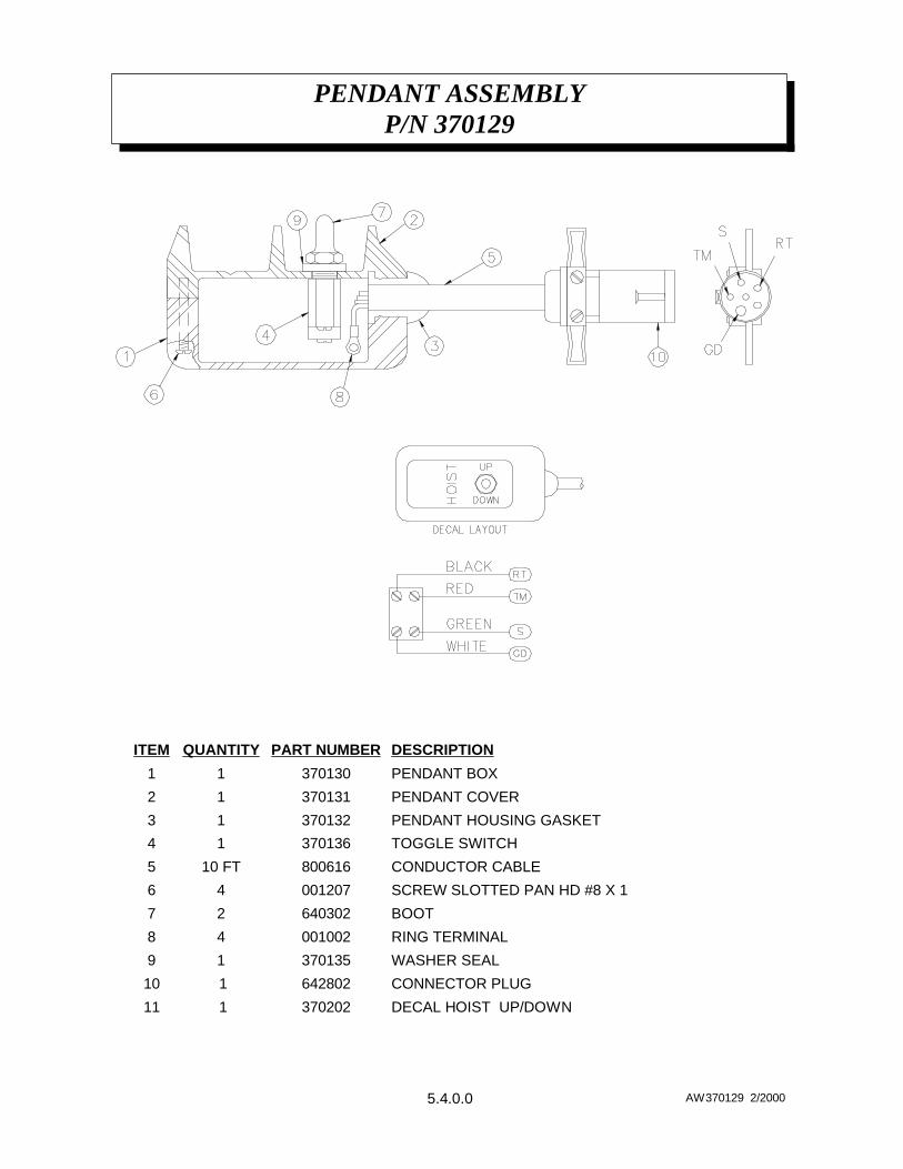
PENDANT ASSEMBLY370129118
WINCH ASSEMBLY272419117
SHEAVE ASSEMBLY (BEARING ONLY 200100)227401116
TRAVELING BLOCK100300115
LOCK PIN370002114
WASHER SP LK 1/4020200213
SCREW HX HD 1/4-20 NC005901212
LOCK PIN370001111
BEARING NEEDLE ROLLER (SEE NOTE 2)370033110
BEARING BALL33019219
BEARING RACE (SEE NOTE 1)37003418
QUILL ASSEMBLY37021517
UPPER BOOM (7 FT BOOM)37004616
UPPER BOOM37004115
LOWER BOOM (7 FT BOOM)37004514
LOWER BOOM37004013
PEDESTAL WELDMENT (TALL)370027-00112
PEDESTAL WELDMENT37021611
DESCRIPTIONPART NUMBERQUANTITYITEM
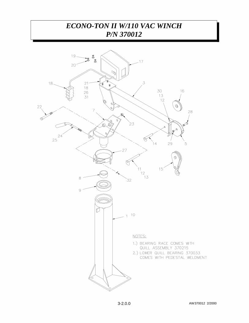
ECONO-TON II W/110 VAC WINCHP/N 370012
3-2.0.0 AW370012 2/2000
ECONO-TON II W/110 VAC WINCHP/N 370012
P/N 370000
3-2.1.0 BM370012 2/2000
COTTER PINREF132
NUT HX 1/4-20 NC015900231
EXTENSION LOCK PAD370005130
NUT HX-LOCK 5/8-18 NF018100129
SCREW HX HD 5/8-18 NF X 1 3/4012200128
WELDMENT BRAKE BAND370003127
WASHER LOCK INT 1/4020201226
GRIP HANDLE272055125
HANDLE BRAKE272052124
NUT HX-LOCK 3/4-16 NF018600123
SCREW HX HD 3/4-16 NF X 7014302122
COVER PLATE370141121
WASHER SP LK 1/2021500320
NUT HX 1/2-13 NC017701319
SCREW HX 1/4-20 NC X 5/8005401218
WINCH ASSEMBLY370146117
SHEAVE ASSEMBLY (BEARING ONLY 200100)227401116
TRAVELING BLOCK100300115
LOCK PIN370002114
WASHER SP LK 1/4020200213
SCREW HX HD 1/4-20 NC005901212
LOCK PIN370001111
BEARING NEEDLE ROLLER (SEE NOTE 2)370033110
BEARING BALL33019219
BEARING RACE (SEE NOTE 1)37003418
QUILL ASSEMBLY37002617
---6
UPPER BOOM37004115
---4
LOWER BOOM37004013
---2
PEDESTAL WELDMENT37002711
DESCRIPTIONPART NUMBERQUANTITYITEM
ECONO-TON II W/110 VAC WINCHW/PENDANT P/N 370140
3-3.0.0 AW370140 2/2000
ECONO-TON II W/110 VAC WINCHW/PENDANT P/N 370140
P/N 370000
3-3.1.0 BM370140 2/2000
GROUND FAULT INTERUPTERREF133
COTTER PIN022804132
NUT HX 1/4-20 NC015900231
EXTENSION LOCK PAD370005130
NUT HX-LOCK 5/8-18 NF018100129
SCREW HX HD 5/8-18 NF X 1 3/4012200128
WELDMENT BRAKE BAND370003127
WASHER LOCK INT 1/4020201226
GRIP HANDLE272055125
HANDLE BRAKE272052124
NUT HX-LOCK 3/4-16 NF018600123
SCREW HX HD 3/4-16 NF X 7014302122
COVER PLATE370141121
WASHER SP LK 1/2021500320
NUT HX 1/2-13 NC017701319
SCREW HX 1/4-20 NC X 5/8005401218
WINCH ASSEMBLY370144117
SHEAVE ASSEMBLY (BEARING ONLY 200100)227401116
TRAVELING BLOCK100300115
LOCK PIN370002114
WASHER SP LK 1/4020200213
SCREW HX HD 1/4-20 NC005901212
LOCK PIN370001111
BEARING NEEDLE ROLLER (SEE NOTE 2)370033110
BEARING BALL33019219
BEARING RACE (SEE NOTE 1)37003418
QUILL ASSEMBLY37002617
UPPER BOOM (7 FT BOOM)37004616
UPPER BOOM37004115
LOWER BOOM (7 FT BOOM)37004514
LOWER BOOM37004013
PEDESTAL WELDMENT (TALL)370027-00112
PEDESTAL WELDMENT37002711
DESCRIPTIONPART NUMBERQUANTITYITEM
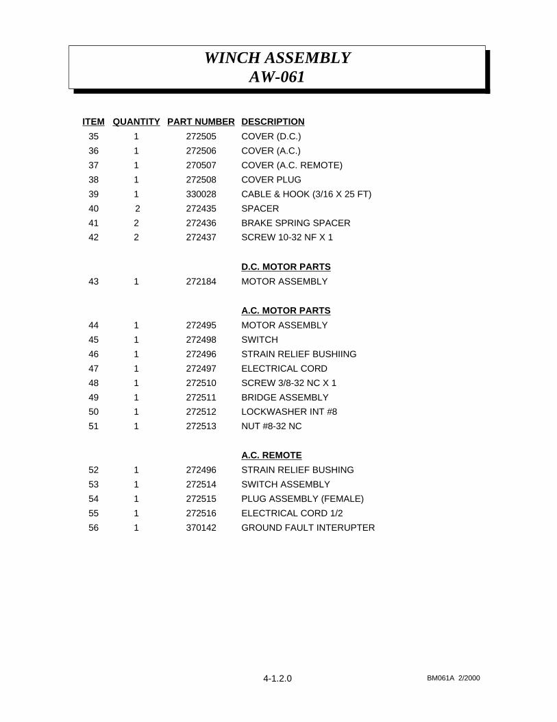
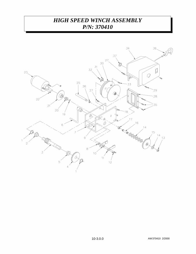
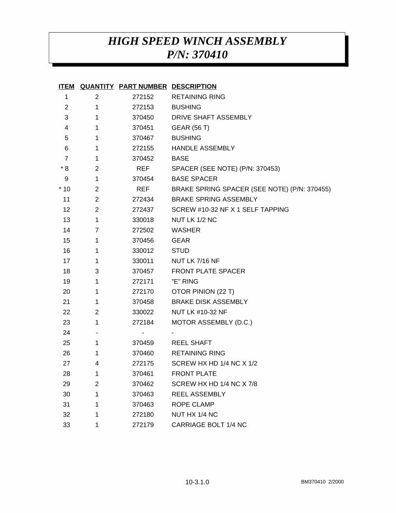
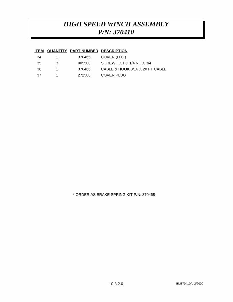
WINCH ASSEMBLYAW-061
4-1.0.0 AW061 2/2000
WINCH ASSEMBLYAW-061P/N 370000
4-1.1.0 BM061 2/2000
CARRIAGE BOLT 1/4-20 NC X 3/4272504134
ROPE CLAMP272180133
NUT HX 1/4-20 NC272179132
REEL ASSEMBLY272503131
WASHER272176230
SCREW 1/4-20 NC 3/4272175429
RETAINING RING272174128
REEL SHAFT272173127
BASE SPACER272172126
“E” RING272171125
12 T PINION GEAR272170124
BRAKE DISC ASSEMBLY272433123
NUT HX LK10-32 NF330022222
LEVEL WIND330019121
LEVEL WIND PIN272165120
FRONT PLATE272164119
SPACER272163318
SCREW 1/4-20 NC X 1 1/16 272162517
BRAKE SPRING ASSEMBLY272434216
GEAR ASSEMBLY330015115
WASHER272502714
LOCKNUT 1/2330018113
CLUTCH STUD330012112
NUT HX LK 7/16-20 NF 330011111
BASE272160110
“E” RING27215919
INTERMEDIATE DRIVE SHAFT ASSEMBLY27215818
DRIVE SHAFT BEARING HOUSING ASSEMBLY27250117
HANDLE ASSEMBLY27215516
GEAR 56 T27215415
BUSHING27215324
RETAINING RING27215223
PRIMARY DRIVE SHAFT ASSEMBLY27215112
BEARING HOUSING ASSEMBLY27250011
DESCRIPTIONPART NUMBERQUANTITYITEM
WINCH ASSEMBLYAW-061P/N 370000
4-1.2.0 BM061A 2/2000
GROUND FAULT INTERUPTER370142156
ELECTRICAL CORD 1/2272516155
PLUG ASSEMBLY (FEMALE)272515154
SWITCH ASSEMBLY272514153
STRAIN RELIEF BUSHING272496152
A.C. REMOTE
NUT #8-32 NC272513151
LOCKWASHER INT #8 272512150
BRIDGE ASSEMBLY 272511149
SCREW 3/8-32 NC X 1272510148
ELECTRICAL CORD272497147
STRAIN RELIEF BUSHIING272496146
SWITCH272498145
MOTOR ASSEMBLY 272495144
A.C. MOTOR PARTS
MOTOR ASSEMBLY272184143
D.C. MOTOR PARTS
SCREW 10-32 NF X 1272437242
BRAKE SPRING SPACER272436241
SPACER272435 240
CABLE & HOOK (3/16 X 25 FT) 330028139
COVER PLUG272508138
COVER (A.C. REMOTE)270507137
COVER (A.C.)272506136
COVER (D.C.)272505135
DESCRIPTIONPART NUMBERQUANTITYITEM
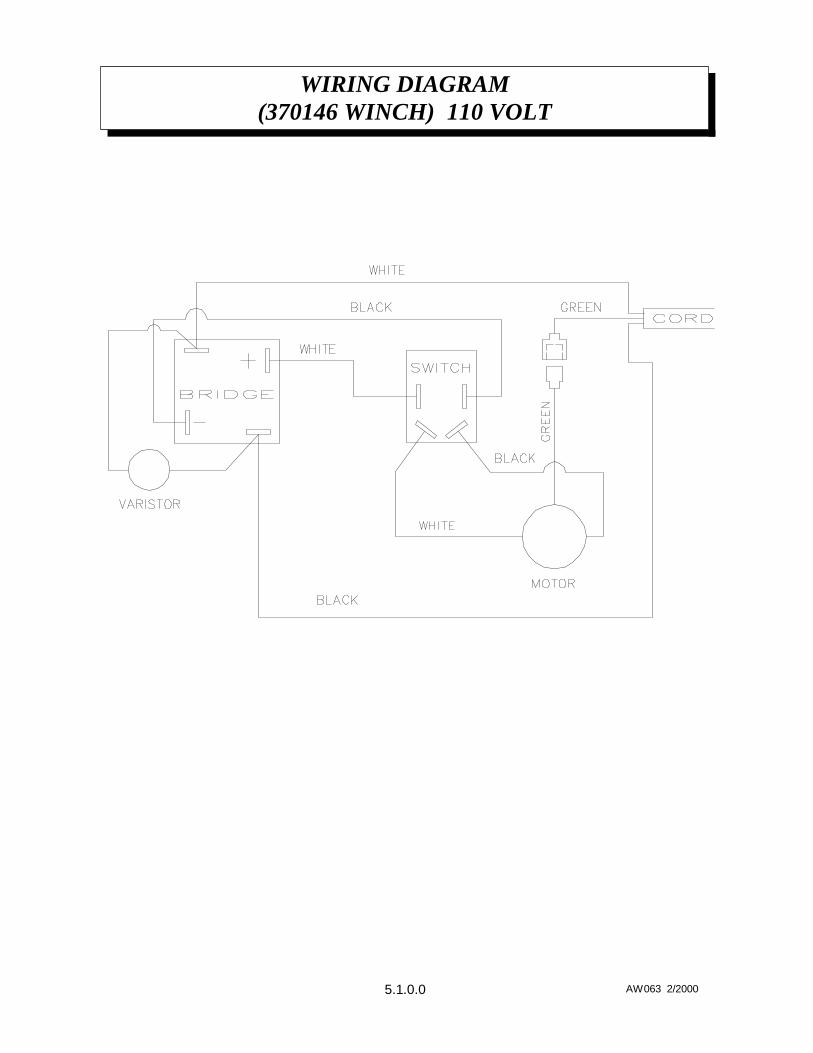
WIRING DIAGRAM(370146 WINCH) 110 VOLT
5.1.0.0 AW063 2/2000
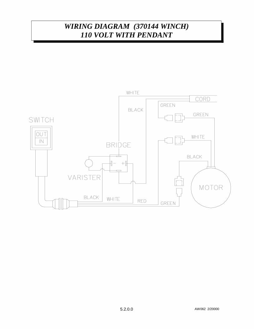
WIRING DIAGRAM (370144 WINCH)110 VOLT WITH PENDANT
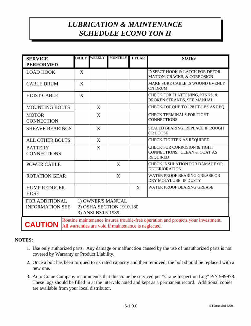
WATER PROOF BEARING GREASE ORDRY MOLYLUBE IF DUSTY
XROTATION GEAR
CHECK INSULATION FOR DAMAGE ORDETERIORATION
XPOWER CABLE
CHECK FOR CORROSION & TIGHTCONNECTIONS. CLEAN & COAT ASREQUIRED
XBATTERY CONNECTIONS
CHECK-TIGHTEN AS REQUIREDXALL OTHER BOLTS
SEALED BEARING, REPLACE IF ROUGHOR LOOSE
XSHEAVE BEARINGS
CHECK TERMINALS FOR TIGHTCONNECTIONS
XMOTORCONNECTION
CHECK-TORQUE TO 128 FT-LBS AS REQ.XMOUNTING BOLTS
CHECK FOR FLATTENING, KINKS, &BROKEN STRANDS, SEE MANUAL
XHOIST CABLE
MAKE SURE CABLE IS WOUND EVENLYON DRUM
XCABLE DRUM
INSPECT HOOK & LATCH FOR DEFOR-MATION, CRACKS, & CORROSION
XLOAD HOOK
NOTES1 YEARMONTHLYWEEKLYDAILYSERVICE PERFORMED
Routine maintenance insures trouble-free operation and protects your investment.All warranties are void if maintenance is neglected. CAUTION
NOTES:
1. Use only authorized parts. Any damage or malfunction caused by the use of unauthorized parts is notcovered by Warranty or Product Liability.
2. Once a bolt has been torqued to its rated capacity and then removed; the bolt should be replaced with anew one.
3. Auto Crane Company recommends that this crane be serviced per “Crane Inspection Log” P/N 999978.These logs should be filled in at the intervals noted and kept as a permanent record. Additional copiesare available from your local distributor.
LUBRICATION & MAINTENANCESCHEDULE ECONO TON II
ET2mtschd 6/996-1.0.0
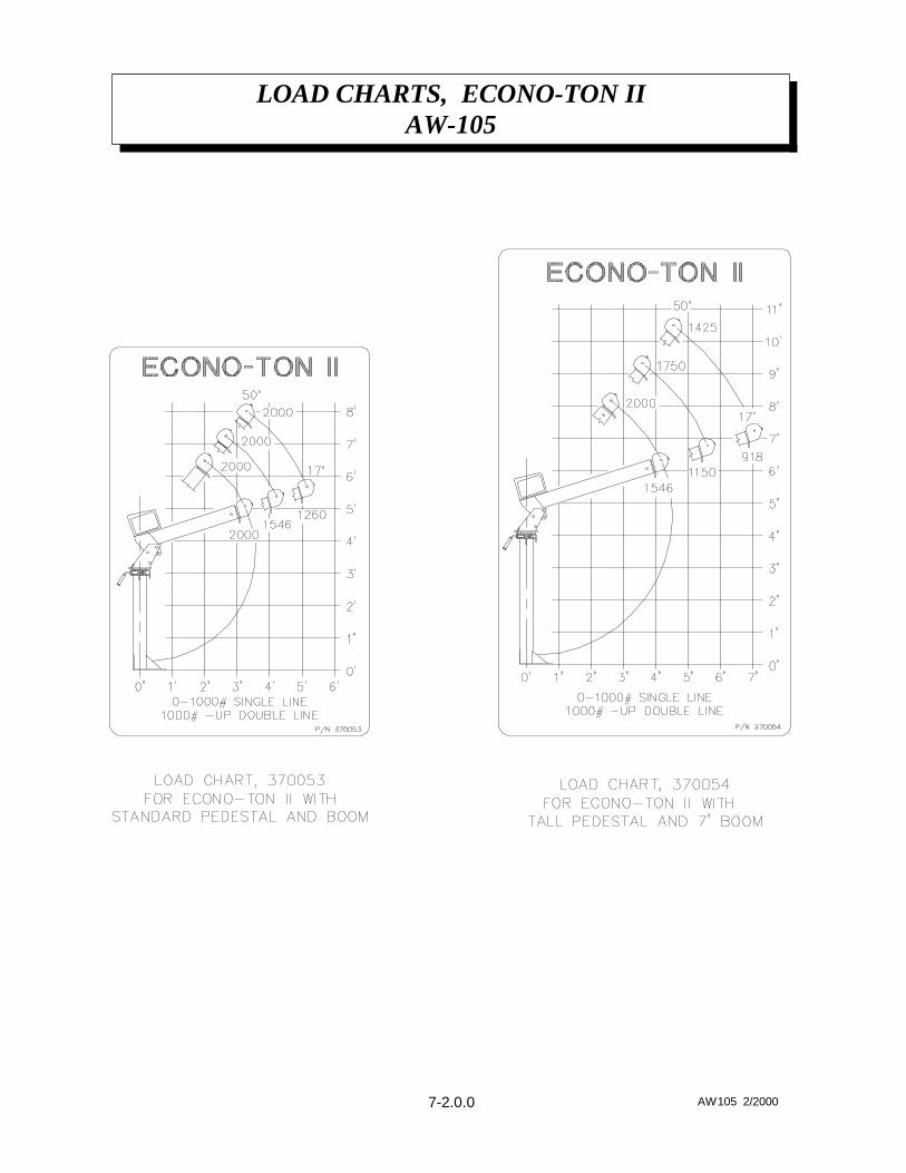
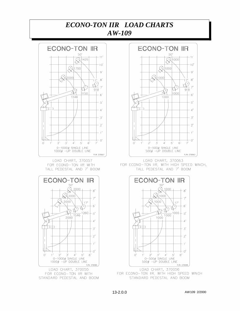
LOAD CHARTS, ECONO-TON IIAW-105
7-2.0.0 AW105 2/2000
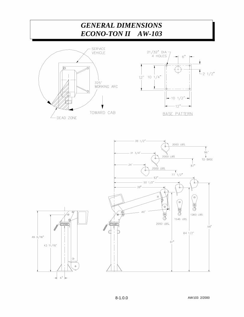
GENERAL DIMENSIONSECONO-TON II AW-103
8-1.0.0 AW103 2/2000
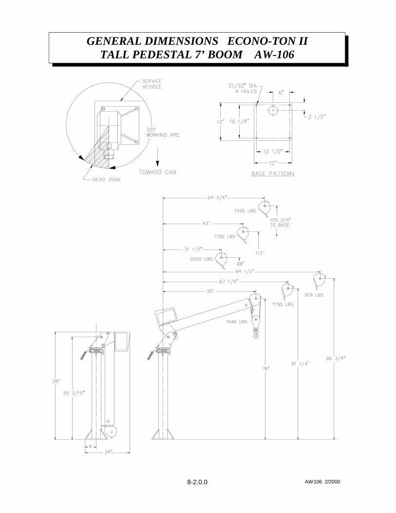
GENERAL DIMENSIONS ECONO-TON IITALL PEDESTAL 7’ BOOM AW-106
8-2.0.0 AW106 2/2000
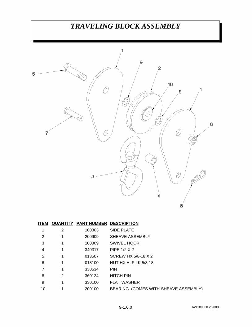
TRAVELING BLOCK ASSEMBLY
9-1.0.0 AW100300 2/2000
BEARING (COMES WITH SHEAVE ASSEMBLY)200100110
FLAT WASHER33010019
HITCH PIN36012428
PIN33063417
NUT HX HLF LK 5/8-1801810016
SCREW HX 5/8-18 X 2 01350715
PIPE 1/2 X 234031714
SWIVEL HOOK10030913
SHEAVE ASSEMBLY20090912
SIDE PLATE10030321
DESCRIPTIONPART NUMBERQUANTITYITEM
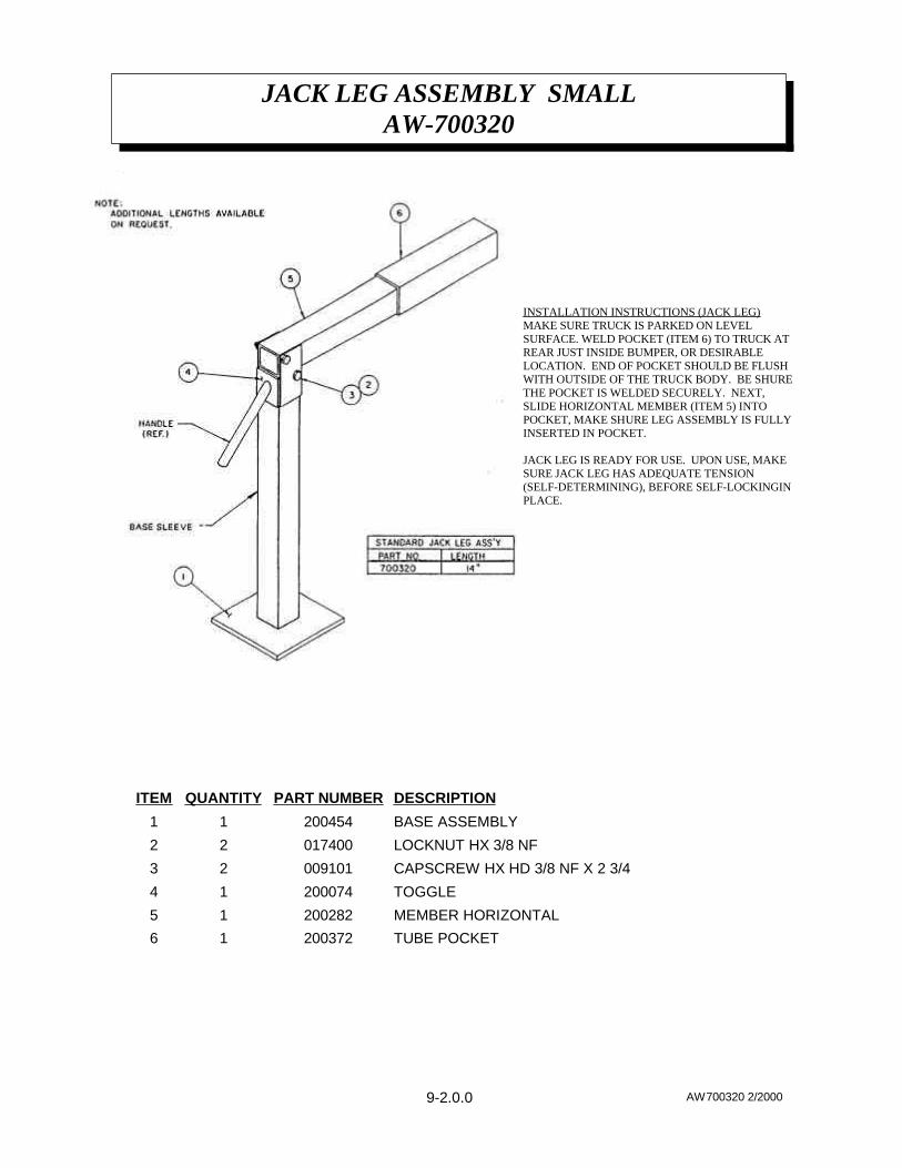
INSTALLATION INSTRUCTIONS (JACK LEG)MAKE SURE TRUCK IS PARKED ON LEVELSURFACE. WELD POCKET (ITEM 6) TO TRUCK ATREAR JUST INSIDE BUMPER, OR DESIRABLELOCATION. END OF POCKET SHOULD BE FLUSHWITH OUTSIDE OF THE TRUCK BODY. BE SHURETHE POCKET IS WELDED SECURELY. NEXT,SLIDE HORIZONTAL MEMBER (ITEM 5) INTOPOCKET, MAKE SHURE LEG ASSEMBLY IS FULLYINSERTED IN POCKET.
JACK LEG IS READY FOR USE. UPON USE, MAKESURE JACK LEG HAS ADEQUATE TENSION(SELF-DETERMINING), BEFORE SELF-LOCKINGINPLACE.
JACK LEG ASSEMBLY SMALLAW-700320
9-2.0.0 AW700320 2/2000
TUBE POCKET20037216
MEMBER HORIZONTAL20028215
TOGGLE20007414
CAPSCREW HX HD 3/8 NF X 2 3/400910123
LOCKNUT HX 3/8 NF01740022
BASE ASSEMBLY20045411
DESCRIPTIONPART NUMBERQUANTITYITEM
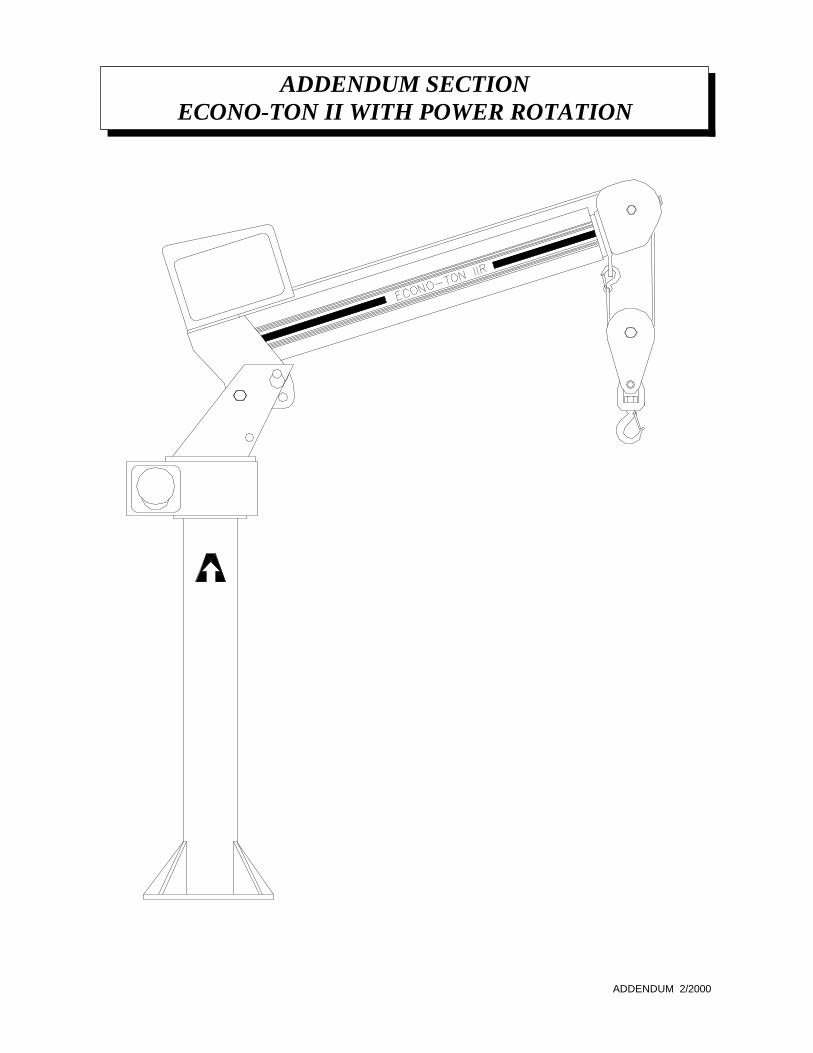
ADDENDUM SECTIONECONO-TON II WITH POWER ROTATION
ADDENDUM 2/2000
ECONO-TON IIRP/N 370400-200 AND 370400-300
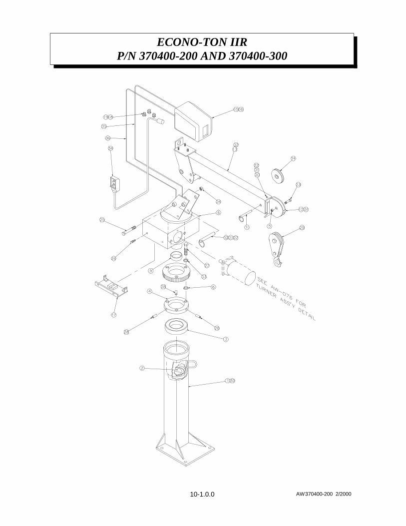
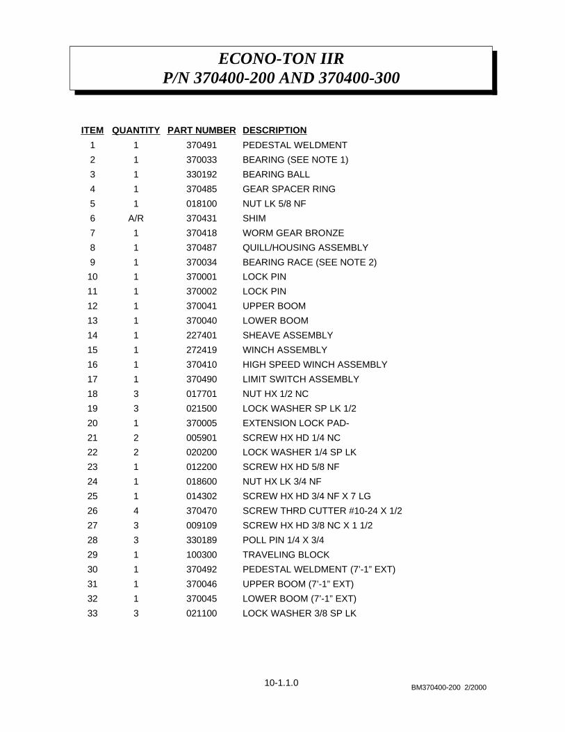
10-1.0.0 AW370400-200 2/2000
ECONO-TON IIRP/N 370400-200 AND 370400-300
P/N 370000
10-1.1.0 BM370400-200 2/2000
LOCK WASHER 3/8 SP LK021100333
LOWER BOOM (7’-1” EXT)370045132
UPPER BOOM (7’-1” EXT)370046131
PEDESTAL WELDMENT (7’-1” EXT)370492130
TRAVELING BLOCK100300129
POLL PIN 1/4 X 3/4 330189328
SCREW HX HD 3/8 NC X 1 1/2009109327
SCREW THRD CUTTER #10-24 X 1/2370470426
SCREW HX HD 3/4 NF X 7 LG014302125
NUT HX LK 3/4 NF018600124
SCREW HX HD 5/8 NF012200123
LOCK WASHER 1/4 SP LK020200222
SCREW HX HD 1/4 NC005901221
EXTENSION LOCK PAD-370005120
LOCK WASHER SP LK 1/2 021500319
NUT HX 1/2 NC017701318
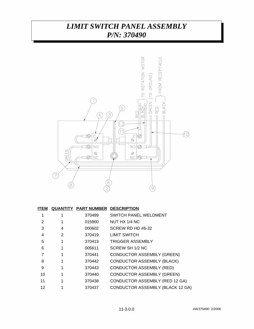
LIMIT SWITCH ASSEMBLY370490117
HIGH SPEED WINCH ASSEMBLY370410116
WINCH ASSEMBLY272419115
SHEAVE ASSEMBLY227401114
LOWER BOOM370040113
UPPER BOOM370041112
LOCK PIN370002111
LOCK PIN370001110
BEARING RACE (SEE NOTE 2)37003419
QUILL/HOUSING ASSEMBLY37048718
WORM GEAR BRONZE37041817
SHIM370431A/R6
NUT LK 5/8 NF01810015
GEAR SPACER RING37048514
BEARING BALL33019213
BEARING (SEE NOTE 1)37003312
PEDESTAL WELDMENT37049111
DESCRIPTIONPART NUMBERQUANTITYITEM
NOTES:1. ITEM NO. 2 IS INCLUDED AS PART OF ITEM 1, AND 30, PEDESTAL WELDMENT.
2. ITEM 9, BEARING RACE, IS PART OF ITEM 8, QUILL HOUSING ASSEMBLY.
ECONO-TON IIRP/N 370400-200 AND 370400-300
P/N 370000
10-1.2.0 BM370400-200A 2/2000
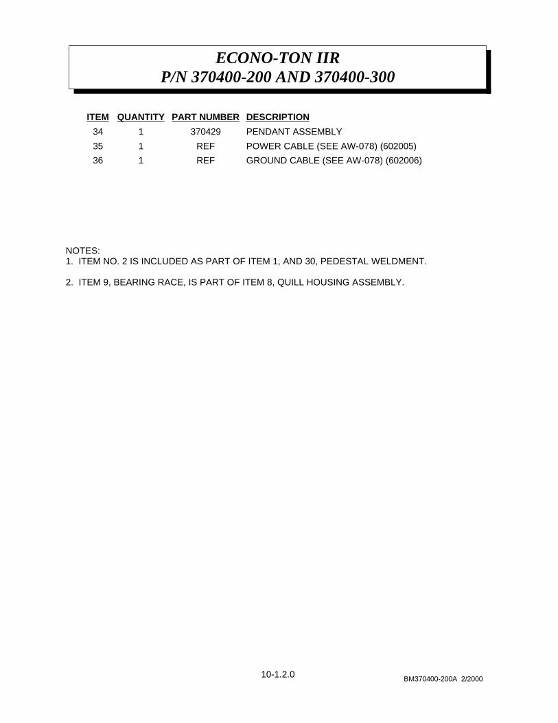
GROUND CABLE (SEE AW-078) (602006)REF136
POWER CABLE (SEE AW-078) (602005)REF135
PENDANT ASSEMBLY370429134
DESCRIPTIONPART NUMBERQUANTITYITEM
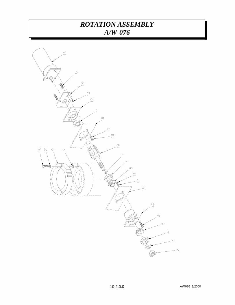
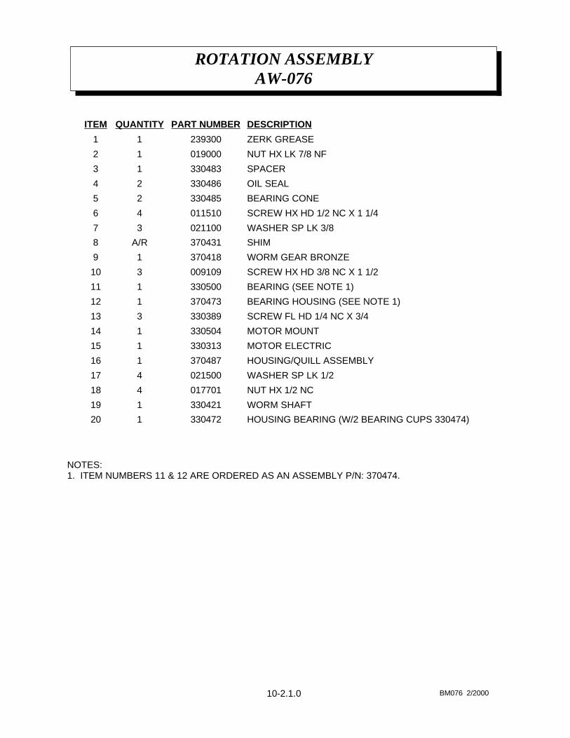
ROTATION ASSEMBLYA/W-076
10-2.0.0 AW076 2/2000
NOTES:1. ITEM NUMBERS 11 & 12 ARE ORDERED AS AN ASSEMBLY P/N: 370474.