Automated Tactical Maneuver Discovery, Reasoning and Trajectory Planning for Autonomous Driving Tianyu Gu † , John M. Dolan †,‡ and Jin-Woo Lee ∤ Abstract— In a hierarchical motion planning system for urban autonomous driving, it is a common practice to separate tactical reasoning from the lower-level trajectory planning. This separation makes it difficult to achieve robust maneuver-based tactical reasoning, which is intrinsically linked to trajectory planning. We therefore propose a planning method that au- tomatically discovers tactical maneuver patterns, and fuses pattern reasoning and sampling-based trajectory planning. The results demonstrate enhanced planning feasibility, coherency and scalability. I. I NTRODUCTION In order to realize fully autonomous driving in urban environments 1 , an autonomous vehicle is typically equipped with a hierarchical planning system to handle different aspects. As reviewed in Buehler [1], many entries in the 2007 DARPA Urban Challenge (UC) used a hierarchical planning system, in which tactical planning (a.k.a. behavior planning) and trajectory planning are separately implemented (the separation). The former is responsible for generating tactical decisions, while the latter generates the executable trajectory. The tactical planning can be further classified as: • Rule-based tactics: speed limits, work zone, stopping at stop sign and intersection precedence handling. • Route-based tactics: choose which lane to switch to in order to meet global routing requirements. • Maneuver-based tactic: decide when and how to yield, follow or overtake other agents. Rule-based and route-based tactical planning can be handled decoupled from trajectory planning with State Machines [2], [3], [4], or other Action Selection Mechanisms [5], [6]. However, the separation poses hard-to-reconcile challenges to implementing maneuver-based tactics with a trajectory planner: Challenge 1: Maneuver feasibility conflict. Maneuver- based tactical planning does not explicitly guarantee plan feasibility, which may result in infeasible maneuver decisions from the perspective of the trajectory planner 2 . Challenge 2: Ignorance of the environment’s topology. The neglect of the environment’s topological structure by † Electrical & Computer Engineering Department, Carnegie Mellon University, Pittsburgh, PA, USA [email protected]‡ Robotics Institute, School of Computer Science, Carnegie Mellon University, Pittsburgh, PA, USA [email protected]∤ Research & Development, General Motors, Warren, Detroit, USA 1 The most common driving situations considered in this paper is are on- road and at-intersection. 2 A practical solution to reduce such inconsistency is to design conserva- tive decision rules, but this does not provide any formal guarantee, and also comes at the price of limiting the vehicle maneuverability. both tactical and trajectory planning can lead to inconsistent outcomes from cycle to cycle. Challenge 3: Unscalable manual scenario discovery. It is not practical to pre-design maneuver-based tactical rules for all unforeseen situations, which can quickly become very complex with multiple objects. This paper addresses these three challenges. To guarantee trajectory feasibility (Challenge 1), we divide the maneuver- based aspect from the tactical planning, and fuse it with motion planning in order to simultaneously perform tactical reasoning and trajectory planning. To incorporate topology awareness (Challenge 2) and remove manual tactical rule design (Challenge 3), we develop maneuver pattern identi- fication that explicitly discovers and reasons about patterns. II. RELATED WORK State machines or decision trees with hand-crafted rules are often used to perform maneuver-based tactical reasoning. Fig.1 illustrates two common maneuver triggering rules designed for lane-change and stop-and-go at intersections. While these rules are able to handle basic traffic situations, they are often challenged in the real world when the on- road or intersection traffic is dense. Intended maneuvers may fail due to the rules being conservatively designed in order to compensate for the fact that they do not guarantee trajectory feasibility/admissibility. Another limitation is that such predefined rules are not general and robust enough to handle varied situations, e.g., when the real-world objects do not match any pre-defined configuration template. v host D gap v car1 v car 2 (a) Lane change v car1 v car2 v car 3 D gap Intersection Zone (b) To-go at intersection Fig. 1: Maneuver-based tactical rules for lane-change and lane- merge behaviors. In (a), lane change is triggered according to a triggering condition, e.g., Dgap above a certain threshold. In (b), stopping at the intersection is part of rule-based tactical planning, but going is often triggered with an empirical safety rule, like the estimated time of zone arrival T of all relevant moving targets being above a threshold. The lower-level trajectory planners designed for UC and nearly all subsequent efforts [7], [8], [9], [10], [11], [12] aimed at optimizing (minimizing) an objective (cost) func-
Transcript
Automated Tactical Maneuver Discovery, Reasoning and TrajectoryPlanning for Autonomous Driving
Tianyu Gu†, John M. Dolan†,‡ and Jin-Woo Lee∤
Abstract— In a hierarchical motion planning system forurban autonomous driving, it is a common practice to separatetactical reasoning from the lower-level trajectory planning. Thisseparation makes it difficult to achieve robust maneuver-basedtactical reasoning, which is intrinsically linked to trajectoryplanning. We therefore propose a planning method that au-tomatically discovers tactical maneuver patterns, and fusespattern reasoning and sampling-based trajectory planning. Theresults demonstrate enhanced planning feasibility, coherencyand scalability.
I. INTRODUCTION
In order to realize fully autonomous driving in urbanenvironments1, an autonomous vehicle is typically equippedwith a hierarchical planning system to handle differentaspects. As reviewed in Buehler [1], many entries in the2007 DARPA Urban Challenge (UC) used a hierarchicalplanning system, in which tactical planning (a.k.a. behaviorplanning) and trajectory planning are separately implemented(the separation). The former is responsible for generatingtactical decisions, while the latter generates the executabletrajectory. The tactical planning can be further classified as:
• Rule-based tactics: speed limits, work zone, stoppingat stop sign and intersection precedence handling.
• Route-based tactics: choose which lane to switch to inorder to meet global routing requirements.
• Maneuver-based tactic: decide when and how to yield,follow or overtake other agents.
Rule-based and route-based tactical planning can be handleddecoupled from trajectory planning with State Machines [2],[3], [4], or other Action Selection Mechanisms [5], [6].However, the separation poses hard-to-reconcile challengesto implementing maneuver-based tactics with a trajectoryplanner:
Challenge 1: Maneuver feasibility conflict. Maneuver-based tactical planning does not explicitly guarantee planfeasibility, which may result in infeasible maneuver decisionsfrom the perspective of the trajectory planner2.
Challenge 2: Ignorance of the environment’s topology.The neglect of the environment’s topological structure by
‡ Robotics Institute, School of Computer Science, Carnegie MellonUniversity, Pittsburgh, PA, USA [email protected]
∤ Research & Development, General Motors, Warren, Detroit, USA1The most common driving situations considered in this paper is are on-
road and at-intersection.2A practical solution to reduce such inconsistency is to design conserva-
tive decision rules, but this does not provide any formal guarantee, and alsocomes at the price of limiting the vehicle maneuverability.
both tactical and trajectory planning can lead to inconsistentoutcomes from cycle to cycle.
Challenge 3: Unscalable manual scenario discovery. It isnot practical to pre-design maneuver-based tactical rules forall unforeseen situations, which can quickly become verycomplex with multiple objects.
This paper addresses these three challenges. To guaranteetrajectory feasibility (Challenge 1), we divide the maneuver-based aspect from the tactical planning, and fuse it withmotion planning in order to simultaneously perform tacticalreasoning and trajectory planning. To incorporate topologyawareness (Challenge 2) and remove manual tactical ruledesign (Challenge 3), we develop maneuver pattern identi-fication that explicitly discovers and reasons about patterns.
II. RELATED WORK
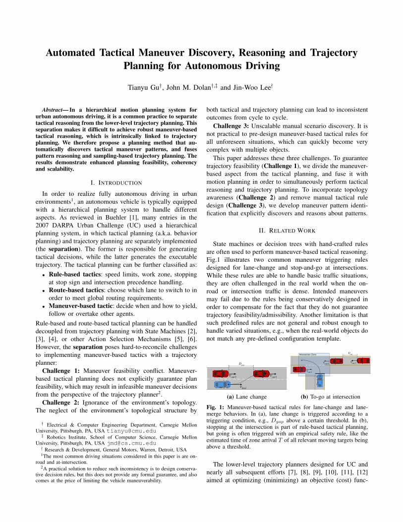
State machines or decision trees with hand-crafted rulesare often used to perform maneuver-based tactical reasoning.Fig.1 illustrates two common maneuver triggering rulesdesigned for lane-change and stop-and-go at intersections.While these rules are able to handle basic traffic situations,they are often challenged in the real world when the on-road or intersection traffic is dense. Intended maneuversmay fail due to the rules being conservatively designed inorder to compensate for the fact that they do not guaranteetrajectory feasibility/admissibility. Another limitation is thatsuch predefined rules are not general and robust enough tohandle varied situations, e.g., when the real-world objects donot match any pre-defined configuration template.
vhost
Dgap
vcar1vcar2
(a) Lane change
vcar1
vcar2 vcar3
DgapIntersection Zone
(b) To-go at intersection
Fig. 1: Maneuver-based tactical rules for lane-change and lane-merge behaviors. In (a), lane change is triggered according to atriggering condition, e.g., Dgap above a certain threshold. In (b),stopping at the intersection is part of rule-based tactical planning,but going is often triggered with an empirical safety rule, like theestimated time of zone arrival T of all relevant moving targets beingabove a threshold.
The lower-level trajectory planners designed for UC andnearly all subsequent efforts [7], [8], [9], [10], [11], [12]aimed at optimizing (minimizing) an objective (cost) func-
tion3. However, neither the tactical planners discussed abovenor the trajectory planners are able to distinguish topolog-ically distinct maneuver patterns. This can lead to “com-peting” locally optimal trajectories that belong to differentpatterns, which can further cause unstable behavior, e.g,cycle-to-cycle planning outcome oscillation (Fig. 2).
Fig. 2: The ignorance of topology in planning. The plot showsa pure path planning problem with a single static obstacle. Twohomological/homotopic classes of paths exist: left (red region) andright (green region). There is a local optimal path within each class(the red/green dashed curves). Under symmetric cost definition, thetwo locally optimal paths can be very close (even tied) in cost,which causes indecisive alternation between the two locally optimalpaths, which can further cause undesirable driving behaviors.
Topological trajectory planning algorithms have been stud-ied in robotics. Triangulation [13], cell-decomposition [14],visibility-graph [14] and reference frame methods [15] havebeen developed to capture the topological structures of therobot’s configuration space. Kuderer [16] and Park [17]proposed to perform topological analysis for mobile robotswith Voronoi diagrams and cell decomposition respectively.However, these methods are limited to co-terminal4 2-Dpaths. Moreover, the need to generate the complete topologygraph causes exponential growth in its size along with thenumber of obstacles. Finally, these methods are only easilyapplied in near-/relative-static environment. For example,Park [17] performed an experiment for freeway autonomousdriving. However, a static snapshot of the moving obstaclesis used to perform cell decomposition rather than taking intoaccount the predicted motion of surrounding vehicles.
Inspired by electromagnetic theory, Bhattacharya [18]proposed to calculate an invariant “signature” to identifydifferent homological 3-D paths. He further augmented thetopological information to graph search to explore differenthomological paths. However, this method is also limited toco-terminal paths, which is not directly applicable to fixed-time-horizon spatiotemporal trajectory planning5.
In this paper, we introduce the idea of fusing the traditionalsampling-based trajectory planner with topological analysisto automatically discover and reason about tactical maneuverpatterns, and guarantee the feasibility of the trajectory plan.We propose pseudo-homology to classify topologically dif-ferent trajectories that are not necessarily co-terminal. Thisplanner is evaluated in several on-road driving scenarios withtime-varying surrounding objects for obstacle avoidance,lane-change and intersection handling.
3Often calculated as a scalar value defined as the weighted sum ofmultiple cost (feature) terms
4Co-terminal paths have the same starting point and destination point.5The terminal states up to the sampled time horizon do not converge into
a single space-time state, i.e., the trajectories are not co-terminal.
III. THEORETICAL BACKGROUND
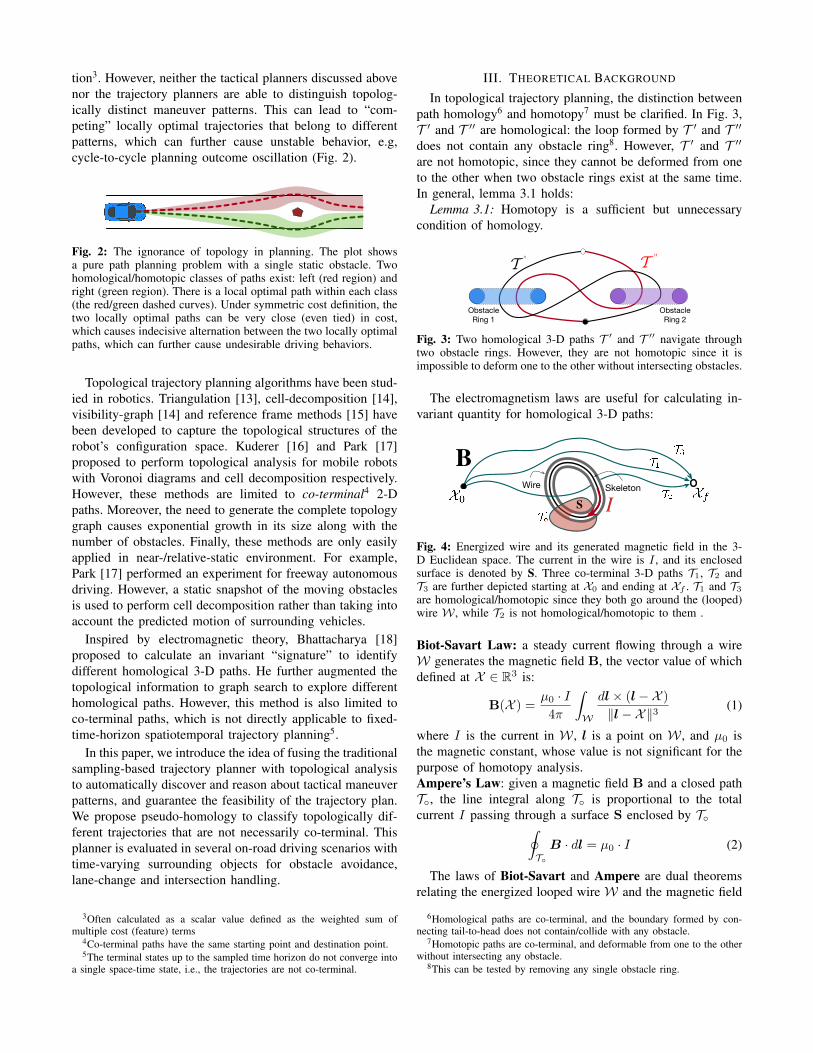
In topological trajectory planning, the distinction betweenpath homology6 and homotopy7 must be clarified. In Fig. 3,T ′ and T ′′ are homological: the loop formed by T ′ and T ′′
does not contain any obstacle ring8. However, T ′ and T ′′
are not homotopic, since they cannot be deformed from oneto the other when two obstacle rings exist at the same time.In general, lemma 3.1 holds:
Lemma 3.1: Homotopy is a sufficient but unnecessarycondition of homology.
T ' T ''
Obstacle Ring 1
Obstacle Ring 2
Fig. 3: Two homological 3-D paths T ′ and T ′′ navigate throughtwo obstacle rings. However, they are not homotopic since it isimpossible to deform one to the other without intersecting obstacles.
The electromagnetism laws are useful for calculating in-variant quantity for homological 3-D paths:
IWire Skeleton
B
S
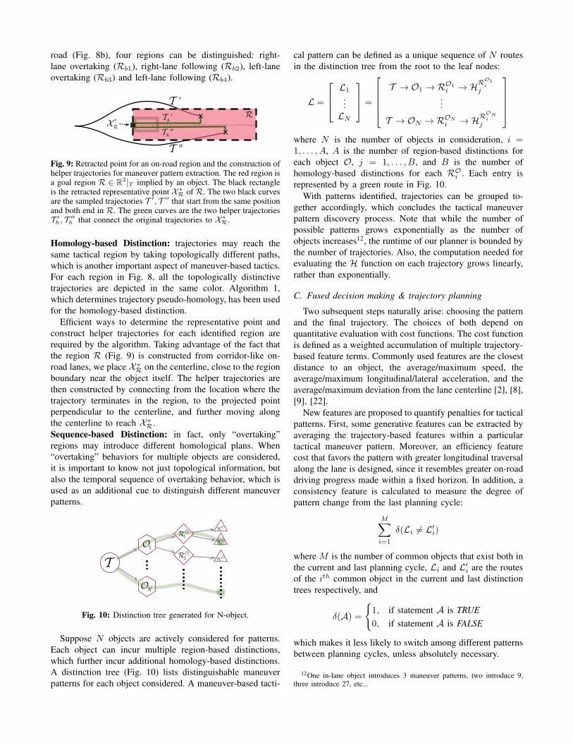
Fig. 4: Energized wire and its generated magnetic field in the 3-D Euclidean space. The current in the wire is I , and its enclosedsurface is denoted by S. Three co-terminal 3-D paths T1, T2 andT3 are further depicted starting at X0 and ending at Xf . T1 and T3
are homological/homotopic since they both go around the (looped)wire W , while T2 is not homological/homotopic to them .
Biot-Savart Law: a steady current flowing through a wireW generates the magnetic field B, the vector value of whichdefined at X ∈ R3 is:
B(X ) =µ0 · I4π
∫W
dl× (l−X )
∥l−X∥3(1)
where I is the current in W , l is a point on W , and µ0 isthe magnetic constant, whose value is not significant for thepurpose of homotopy analysis.Ampere’s Law: given a magnetic field B and a closed pathT◦, the line integral along T◦ is proportional to the totalcurrent I passing through a surface S enclosed by T◦∮
T◦
B · dl = µ0 · I (2)
The laws of Biot-Savart and Ampere are dual theoremsrelating the energized looped wire W and the magnetic field
6Homological paths are co-terminal, and the boundary formed by con-necting tail-to-head does not contain/collide with any obstacle.
7Homotopic paths are co-terminal, and deformable from one to the otherwithout intersecting any obstacle.
8This can be tested by removing any single obstacle ring.
generated. In Fig. 4, regardless of the shape of the closedpath T◦, the integration of magnetic field B gives an Ampereinvariant which is only relevant to the amount of currentgoing through the closed surface S formed by W .
In Bhattacharya [18], this property is exploited to definethe H function for co-terminal paths like T1, T2, T3. Imagineplanning with one (or more) ring-like obstacle, which isenergized with current I and generates a magnetic field Blike the wire W in Fig. 4. The H function is defined as theintegration of the magnetic field B along T :
H(T ) =
∫TB · dl
It can also be shown that the H function gives a numericalequivalent to homology:
Theorem 3.2: paths T ′ and T ′′ are homological if andonly if their H functions are equal.
Note that whether the looped wire has volume is irrelevantto the result of topological analysis. The deformable retract9
of an object O is its homology/homotopy equivalent, or itsskeleton S(O). In Fig. 4, a 1-D curved skeleton S(W) isobtained by “shrinking” the wire W . Replacing W withS(W) does not change the homology/homotopy relationshipamong T1, T2 or T3.
IV. SPATIOTEMPORAL TOPOLOGICAL ANALYSIS
The planning workspace of the autonomous vehicle con-sidered in this paper is a 3-D spatiotemporal space W =[R2×T] obtained by augmenting a 2-D planar space R2 witha time dimension T. A bounded workspace W is consideredin practice due to fixed horizon (T ) at every planning cycle.
Taking the surrounding objects10 into account is the pri-mary goal of motion planning for urban autonomous driving.Taking a snapshot at any given time, an object is representedas a 2-D polygon. Adding the temporal prediction (up toT ) to a 2-D object creates a 3-D temporal object. Fig. 5ashows an on-road driving scenario with a single bicyclist asthe object to avoid. The bicyclist object O is augmented asa pillar-shaped temporal object in OW within W, with itspredicted trajectory (Fig. 5b) as its skeleton S(OW).
However, OW is not able to incur different homologi-cal/homotopic trajectories because it is genus11-0. In orderto introduce this ability, augmented temporal objects OW
of genus-1 are created by augmenting OW with a loop-likestructure in the space W/W ({x|x ∈ W, x /∈ W}). Thiscan be achieved by appending either a finite loop giving OW
◦(Fig. 5c) or through an infinity loop giving OW
∞ (Fig. 5d).The latter, in a fashion that extends both ends of the skeletonto infinity in parallel to the time dimension, is preferredfor its mathematical simplicity. The virtual magnetic field
9Deformable retract is a continuous mapping from the entire space (ob-ject) into a subspace (skeleton) completely contained within. The subspacedoes not alter the topology exhibited by the surface of the original space.
10E.g., static objects, surrounding traffic, bicyclist, pedestrian, etc.11Genus is an important concept in algebraic topology [19]. An intuitive
interpretation of genus is the maximum number of “cuts” that can beperformed on an object such that the cut object is still a connected objectwith full volume, e.g., in 3-D, a ball is genus-0, a loop hole is genus-1, etc.
Host Vehicle Bicyclist
!2
(a) Object in spatial spaceT
T2
0
Genus-0
(b) Temporal object & skeleton in configuration spaceT
T2
0
Genus-1Finite Loop
(c) Augmented skeleton with finite loop
∞
∞ T
T2
0
Genus-1Loop via Infinity
∞
∞
(d) Augmented skeleton with loop through infinity
Fig. 5: The creation of a genus-0 temporal object, its genus-1 augmentation and the virtual magnetic field incurred in theconfiguration space. (a) shows the 2-D spatial space R2 withthe host vehicle and a moving bicyclist O. (b) shows the 3-Dspatiotemporal workspace W and its bounded subspace W. It alsoshows the temporal object OW created from the moving bicyclistO, and its skeleton S(OW). (c) shows the skeleton of an augmentedtemporal object S(OW
◦ ) from outside of the bounded workspace.(d) shows the skeleton of an augmented temporal object S(OW
∞)through infinity.
is further obtained via integration along S(OW∞) to calculate
the H function discussed in section III. A trajectory in W isequivalent to a path in R3. The property of the H functionholds for W.
Furthermore, instead of only analyzing co-terminal paths,it is of practical interest to group trajectories that terminate inthe same 2-D spatial region R2 for on-road driving. Pseudo-homology is therefore formally defined:Pseudo-homology: two paths T ′ and T ′′ are pseudo-homological if they both start from the same state and endin the same path-connected region R ∈ R2.
Similar to the 1-D skeleton being the deformable retractof a 3-D object, a 0-D point is the retract of a 2-D spatialregion R. This point is also referred to as the representativepoint X ∗
R of R. Note that R does not have to be a convexshape, and the exact location of X ∗
R is insignificant as long
T ' T ''
Th ' Th ''
X0
R
XR*
XRT ' XR
T ''
Fig. 6: Pseudo-homological trajectories. Trajectories T ′ and T ′′ arepseudo-homological since they both start from state X0, and end inthe same path-connected region R ∈ R2 at states X T ′
R and X T ′′R .
A representative state X ∗R is specified for R, and helper trajectories
T ′h, T ′′
h in R connect the original trajectories to X ∗R.
as it is contained by R. Then the following corollary is usedto efficiently test for pseudo-homology:Corollary: two trajectories T ′ and T ′′ are pseudo-homological if they can be extended from where they ter-minate on R to X ∗
R with helper trajectories T ′h and T ′′
h , and
H(T ′ + T ′h) = H(T ′′ + T ′′
h )
The helper trajectories can be of arbitrary shape, as long asthey stay within R (Fig. 6). The procedure to determine thepseudo-homology is summarized by algorithm 1:
Algorithm 1 Determine pseudo-homology
Require: Two trajectories T ′ and T ′′
Ensure: Correct judgment of trajectories’ pseudo-homologyIDENTIFY a spatial region R ∈ R2 within W at time T .CHECK if the end states X T ′
and X T ′′are in R.
IF no, RETURN falseRETRACT region R to a representative point X ∗
RCONSTRUCT helper trajectories T ′
h and T ′′h that connect
X T ′
R and X T ′′
R to X ∗R
CALCULATE the H function of T ′ + T ′h and T ′′ + T ′′
h
IF H(T ′ + T ′h) ̸= H(T ′′ + T ′′
h ) RETURN falseELSE RETURN true
Algorithm 1 plays a key role in behavioral discovery insection V for its efficient topological distinguishing capabil-ity as well as its region-awareness.
V. FUSED TACTICAL MANEUVER DISCOVERY,REASONING & MOTION PLANNING
The fusion of tactical maneuver discovery/reasoning andtrajectory planning is achieved in three steps. A pool offeasible and admissible trajectory candidates is first sampled.From this pool, distinct tactical maneuver patterns are auto-matically extracted along with their semantic interpretation.Then the final trajectory is obtained by first deciding on atactical pattern, followed by choosing the optimal trajectorybelonging to the selected pattern.
A. Trajectory sampling
Trajectory samples must first be generated to form a poolof possible maneuver candidates, the foundation of which isthe motion primitives that connect one state to another ina smooth fashion. Decoupled/analytical primitives [20], [21]are used. They allow the trajectory evaluation routine to bebroken into steps, checking for path collision against static
objects first before checking for the trajectory, which cansave computation time by eliminating infeasible spatiotempo-ral trajectory search nodes at an early stage. Their analyticalsolution allows for trivial computation overhead rather thanan iterative optimization effort.
Host Vehicle
Layer 1 Layer 2 Layer 3
Fig. 7: Path sampling pattern for on-road driving. The black curvesrepresent the path candidates sampled in the current lane of the hostvehicle, while the blue curves represent those in the neighboringlane. Each group of paths is sampled by placing three layers ofterminal states along the road with decreasing lateral alternatives.
Another important choice is the sampling pattern, whichdetermines the subspace of the spatiotemporal domain thatthe planner should focus on exploring. There is a trade-offbetween sampling exhaustiveness and the computation over-head. We adopt the classical patterns for on-road driving [8],[9], which involve sampling paths along the road (Fig. 7) andexpanding the spatiotemporal search space by branching overthe sampled polynomial speed profiles. All the trajectoriesare sampled up to a fixed lookahead time horizon T (thenext few seconds) to represent a short-term maneuver.
B. Maneuver-based tactics discovery
Given the trajectory pool, the next goal is to discoverthe maneuver-based tactical patterns and their semantic de-scriptions. Different patterns can be extracted depending onthe spatial area where the trajectory terminates (region-based distinction), how it gets there around the obstacles(homology-based distinction), and what overtaking (if any)order it follows (sequence-based distinction).
Ra1Ra2
(a) Region-based distinction for in-lane object.
Rb1Rb2
Rb3Rb4
(b) Region-based distinction for inter-lane object.
Fig. 8: Region-based and homology-based distinctions for on-roaddriving. (a) shows two corridor regions can be distinguished, Ra1
and Ra2, for an object in a one-lane road. (b) shows four regions aredistinguished, Rb1, Rb2, Rb3 and Rb4, for an object on a two-laneroad. For each region R, there are one or two curves in darker colorrepresenting the possible homological trajectories whose terminalstates are in R.
Region-based Distinction: an object on a single-lane roadnaturally splits the lane into front/back corridor-like regions(Fig. 8a). Region-based pattern distinction is defined bywhich region a trajectory terminates in: object overtaking(Ra1) or following (Ra2). For an object on a two-lane
road (Fig. 8b), four regions can be distinguished: right-lane overtaking (Rb1), right-lane following (Rb2), left-laneovertaking (Rb3) and left-lane following (Rb4).
T '
T ''
Th '
Th ''
RXR
*
Fig. 9: Retracted point for an on-road region and the construction ofhelper trajectories for maneuver pattern extraction. The red region isa goal region R ∈ R2|T implied by an object. The black rectangleis the retracted representative point X ∗
R of R. The two black curvesare the sampled trajectories T ′, T ′′ that start from the same positionand both end in R. The green curves are the two helper trajectoriesT ′h, T ′′
h that connect the original trajectories to X ∗R.
Homology-based Distinction: trajectories may reach thesame tactical region by taking topologically different paths,which is another important aspect of maneuver-based tactics.For each region in Fig. 8, all the topologically distinctivetrajectories are depicted in the same color. Algorithm 1,which determines trajectory pseudo-homology, has been usedfor the homology-based distinction.
Efficient ways to determine the representative point andconstruct helper trajectories for each identified region arerequired by the algorithm. Taking advantage of the fact thatthe region R (Fig. 9) is constructed from corridor-like on-road lanes, we place X ∗
R on the centerline, close to the regionboundary near the object itself. The helper trajectories arethen constructed by connecting from the location where thetrajectory terminates in the region, to the projected pointperpendicular to the centerline, and further moving alongthe centerline to reach X ∗
R.Sequence-based Distinction: in fact, only “overtaking”regions may introduce different homological plans. When“overtaking” behaviors for multiple objects are considered,it is important to know not just topological information, butalso the temporal sequence of overtaking behavior, which isused as an additional cue to distinguish different maneuverpatterns.
T
O1
ON
R1O1
R2O1
H1R1O1
H2R1O1
H1R2O1
Fig. 10: Distinction tree generated for N-object.
Suppose N objects are actively considered for patterns.Each object can incur multiple region-based distinctions,which further incur additional homology-based distinctions.A distinction tree (Fig. 10) lists distinguishable maneuverpatterns for each object considered. A maneuver-based tacti-
cal pattern can be defined as a unique sequence of N routesin the distinction tree from the root to the leaf nodes:
L =
L1
...LN
=
T → O1 → RO1
i → HRO1i
j...
T → ON → RONi → HRON
ij
where N is the number of objects in consideration, i =1, . . . , A, A is the number of region-based distinctions foreach object O, j = 1, . . . , B, and B is the number ofhomology-based distinctions for each RO
i . Each entry isrepresented by a green route in Fig. 10.
With patterns identified, trajectories can be grouped to-gether accordingly, which concludes the tactical maneuverpattern discovery process. Note that while the number ofpossible patterns grows exponentially as the number ofobjects increases12, the runtime of our planner is bounded bythe number of trajectories. Also, the computation needed forevaluating the H function on each trajectory grows linearly,rather than exponentially.
C. Fused decision making & trajectory planning
Two subsequent steps naturally arise: choosing the patternand the final trajectory. The choices of both depend onquantitative evaluation with cost functions. The cost functionis defined as a weighted accumulation of multiple trajectory-based feature terms. Commonly used features are the closestdistance to an object, the average/maximum speed, theaverage/maximum longitudinal/lateral acceleration, and theaverage/maximum deviation from the lane centerline [2], [8],[9], [22].
New features are proposed to quantify penalties for tacticalpatterns. First, some generative features can be extracted byaveraging the trajectory-based features within a particulartactical maneuver pattern. Moreover, an efficiency featurecost that favors the pattern with greater longitudinal traversalalong the lane is designed, since it resembles greater on-roaddriving progress made within a fixed horizon. In addition, aconsistency feature is calculated to measure the degree ofpattern change from the last planning cycle:
M∑i=1
δ(Li ̸= L′i)
where M is the number of common objects that exist both inthe current and last planning cycle, Li and L′
i are the routesof the ith common object in the current and last distinctiontrees respectively, and
δ(A) =
{1, if statement A is TRUE0, if statement A is FALSE
which makes it less likely to switch among different patternsbetween planning cycles, unless absolutely necessary.
The proposed maneuver discovery methods are applied inthree urban driving scenarios:
• S1: one bicyclist and one static object in a single-lanesituation (Fig. 11).
• S2: the host vehicle needs to perform a lane-changewhen there is also a slow-moving bicyclist in the middleof the current lane (Fig. 12).
• S3: one pedestrian crossing in front of the host vehicleat a T-intersection and two moving cars in the targetlane (Fig. 13).
For each scenario, feasible maneuver patterns are firstobtained with the optimal trajectories of each pattern:
XY
T
(a) Spatiotemporal trajectory samples.
1)
2)
3)
0s 10s
(b) Discovered tactical patterns and optimal trajectories.
Fig. 11: Scenario 1: avoid a bicyclist and a static object in a singlelane. (a) shows the spatiotemporal trajectory samples. Three tacticalmaneuver patterns are identified, and trajectories of the same patternare grouped together in the same color. (b) shows the optimaltrajectory of each maneuver pattern, along with the predicted motionof surrounding objects.
For scenario S1, three patterns are identified (Fig. 11a),and the optimal trajectories of each pattern are furtherobtained (Fig. 11b).
1) the host vehicle slows down to follow the bicyclist.Both objects will be avoided in a conservative fashion,i.e., no overtaking.
2) the host vehicle mildly slows down to overtake thebicyclist, and performs a double swerve to avoid bothobjects.
3) the host vehicle overtakes the bicyclist, and stops infront of the static obstacle.
For scenario S2, three patterns are identified, representedby the optimal trajectory of each pattern:
1) the host vehicle slows down to stay behind the bicy-clist. Lane-change is halted indefinitely.
2) the host vehicle slows down to merge into the targetlane after both cars in the target lane pass by.
3) the host vehicle slightly accelerates to merge into thegap between the two cars in the target lane.
1)
2)
3)
0s 10s
Fig. 12: Scenario 2: lane change in traffic with an obstacle in themiddle of the current lane.
1)
2)
3)
0s 10s
Fig. 13: Scenario 3: enter traffic from stationary start at T-intersection with pedestrian and traffic. The figure shows thediscovered patterns, the optimal trajectory for each pattern, and thepredicted motion of surrounding objects.
For scenario S3, three patterns are identified, representedby the optimal trajectory of each pattern:
1) the host vehicle moves after the pedestrian crosses theroad, and merges to follow the second car.
2) the host vehicle accelerates before the pedestriancrosses the road to merge into the gap between thefirst and the second car.
3) the host vehicle stays behind the pedestrian, haltingmerging indefinitely.
The maneuver pattern is further selected based on pattern-level reasoning, which is dependent on the weightings onthe progress/aggressiveness/consistency features. The opti-mal trajectory within the selected pattern is then found forthe final planning output.
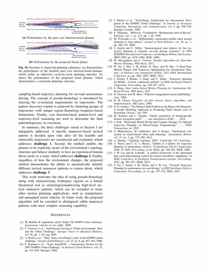
To highlight the benefit of distinguishing tactical ma-neuver patterns in the traditional optimal planning method,we implement a pure cost function-based motion plannerwhose sampling pattern and trajectory-level cost function areidentical to the proposed planner. They are tested side-by-side in scenario S4 (Fig. 14), which consists of a single staticobject in the center of the lane with some sensing noiseadded.
In Fig. 14a, the sensor uncertainty tends to cause inde-cisive (alternating) planning outcomes from the pure costfunction-based planner. The proposed planner, on the otherhand, sticks to swerving around the static object from oneside (Fig. 14b), which demonstrates superior plan consis-tency. The difference results from the explicit exposure ofmaneuver patterns, and the consideration of the “consis-tency” feature in the pattern-level reasoning.
VII. CONCLUSION
In this paper, we propose an automated maneuver-basedtactical pattern discovery/reasoning methodology fused with
Noisy perception of detected static objects
Executed trace of the robot
Red curves: optimal trajectory of the “swerve left” maneuver pattern
Blue curves: optimal trajectory of the “swerve right” maneuver pattern
Grey curves: final optimal trajectory
(a) Performance by the pure cost function-based planner.
Executed trace of the robot
Red curves: optimal trajectory of the “swerve left” maneuver pattern
Blue curves: optimal trajectory of the “swerve right” maneuver pattern
Grey curves: final optimal trajectory
Noisy perception of detected static objects
(b) Performance by the proposed fused planer.
Fig. 14: Scenario 4: improved planning coherency. (a) demonstratesthe performance of the baseline pure cost function-based planner,which yields an indecisive cycle-by-cycle planning outcome. (b)shows the performance of the proposed fused planner, whichdemonstrates a consistent planning outcome.
sampling-based trajectory planning for on-road autonomousdriving. The concept of pseudo-homology is introduced byrelaxing the co-terminal requirements on trajectories. Thepattern discovery routine is achieved by clustering groups oftrajectories with unique region-/homology-/sequence-baseddistinctions. Finally, cost function-based pattern-level andtrajectory-level reasoning are used to determine the finalpattern/trajectory in execution.
In summary, the three challenges raised in Section I areadequately addressed. A specific maneuver-based tacticalpattern is decided upon only after all the feasible andadmissible trajectories are constructed and evaluated, whichaddresses challenge 1. Second, the method enables theplanner to be explicitly aware of the environment’s topologystructure and behave similarly to how an experienced humandriver sticks to a route, which addresses challenge 2. Finally,regardless of how the environment changes, the proposedmethod demonstrates the ability to automatically identifydifferent tactical maneuver patterns to reason about, whichaddresses challenge 3.
This work motivates the idea of using pseudo-homologyalong with characterizing workspace regions as a formaltheoretical tool in extracting/semanticizing high-level tac-tical maneuver patterns, which can be extended to manyother motion planning applications, such as manipulatorsand unmanned aerial vehicles. In future work, the proposedalgorithm will be extended to distinguish subtle maneuverpatterns with more complex reasoning capability.
REFERENCES
[1] M. Buehler, K. Iagnemma, and S. Singh, The DARPA urban challenge:autonomous vehicles in city traffic. 2009.
[2] C. Urmson et al., “Autonomous driving in Urban environments: Bossand the Urban Challenge,” Springer Tracts in Advanced Robotics,vol. 56, pp. 1–59, aug 2009.
[3] A. Bacha et al., “Odin: Team victorTango’s entry in the DARPA urbanchallenge,” Journal of field Robotics, vol. 25, no. 8, pp. 467–492, 2008.
[4] S. Kammel et al., “Team AnnieWAY s Autonomous System for the2007 DARPA Urban Challenge,” in Journal of Field Robotics, vol. 25,pp. 615–639, Springer, 2008.
[5] J. Hurdus et al., “VictorTango Architecture for Autonomous Navi-gation in the DARPA Urban Challenge,” in Journal of AerospaceComputing, Information, and Communication, vol. 5, pp. 506–529,Springer London, 2008.
[6] P. Pirjanian, “Behavior Coordination Mechanisms-state-of-the-art,”Ethology, vol. 1, no. 213, pp. 1–49, 1999.
[7] M. Pivtoraiko et al., “Differentially constrained mobile robot motionplanning in state lattices,” Journal of Field Robotics, vol. 26, no. 3,pp. 308–333, 2009.
[8] J. Ziegler and C. Stiller, “Spatiotemporal state lattices for fast tra-jectory planning in dynamic on-road driving scenarios,” in 2009IEEE/RSJ International Conference on Intelligent Robots and Systems,IROS 2009, pp. 1879–1884, IEEE, 2009.
[9] M. Mcnaughton and C. Urmson, Parallel Algorithms for Real-timeMotion Planning. PhD thesis, 2011.
[10] W. Xu, J. Wei, J. M. Dolan, H. Zhao, and H. Zha, “A Real-TimeMotion Planner with Trajectory Optimization for Autonomous Vehi-cles,” in Robotics and Automation (ICRA), 2012 IEEE InternationalConference on, pp. 2061–2067, IEEE, 2012.
[11] J. Ziegler, P. Bender, T. Dang, and C. Stiller, “Trajectory planningfor Bertha - A local, continuous method,” in IEEE Intelligent VehiclesSymposium, Proceedings, pp. 450–457, 2014.
[12] S. Wang, State Lattice-based Motion Planning for Autonomous On-Road Driving. PhD thesis, 2015.
[13] D. Demyen and M. Buro, “Efficient triangulation-based pathfinding,”Aaai, 2006.
[14] H. M. Choset, Principles of robot motion: theory, algorithms, andimplementation. MIT press, 2005.
[15] K. D. Jenkins, “The Shortest Path Problem in the Plane with Obstacles:A Graph Modeling Approach to Producing Finite Search Lists ofHomotopy Classes,” jun 1991.
[16] M. Kuderer and C. Sprunk, “Online generation of homotopicallydistinct navigation paths,” . . . and Automation (ICRA . . . , 2014.
[17] J. Park, “Homotopy-Based Divide-and-Conquer Strategy for OptimalTrajectory Planning via Mixed-Integer Programming,” . . . , IEEETransactions on, 2015.
[18] S. Bhattacharya, M. Likhachev, and V. Kumar, “Topological con-straints in search-based robot path planning,” Autonomous Robots,vol. 33, no. 3, pp. 273–290, 2012.
[19] A. Hatcher, “Algebraic topology. 2002,” Cambridge UP, Cambridge.[20] A. Piazzi and C. G. L. Bianco, “Quintic G 2-splines for trajectory
planning of autonomous vehicles,” in Intelligent Vehicles Symposium,2000. IV 2000. Proceedings of the IEEE, pp. 198–203, IEEE, 2000.
[21] J. W. Lee and B. Litkouhi, “A unified framework of the automatedlane centering/changing control for motion smoothness adaptation,” inIEEE Conference on Intelligent Transportation Systems, Proceedings,ITSC, pp. 282–287, IEEE, 2012.
[22] T. Gu, J. Snider, J. M. Dolan, and J. W. Lee, “Focused TrajectoryPlanning for autonomous on-road driving,” in IEEE Intelligent VehiclesSymposium, Proceedings, no. Iv, pp. 547–552, IEEE, 2013.