278
AUTOMATIC CALL DISTRIBUTION (ACD) INSTALLATION MANUAL INT-2039 Issue 4.0
AUTOMATIC CALL DISTRIBUTION (ACD)INSTALLATION MANUAL
INT-2039Issue 4.0


NEC Corporation of America reserves the right to change the specifications, or features, atany time, without notice.
NEC Corporation of America has prepared this document for use by its employees andcustomers. The information contained herein is the property of NEC Corporation of Americaand shall not be reproduced without prior written approval from NEC Corporation ofAmerica.
Dterm is a registered trademarks of NEC Corporation of America. UNIVERGE is atrademark of NEC Corporation. Windows is a registered trademark of MicrosoftCorporation. AT&T is a registered trademark of AT&T Wireless Services, Inc. All otherbrand names and product names referenced in this document are trademarks or registeredtrademarks of their respective companies.
Copyright 2013
NEC Corporation of America6535 N. State Highway 161
Irving, TX 75039-2402
Communications Technology Group

___________________________________________________________________________________
TABLE OF CONTENTS
Chapter 1 Introduction
Section 1 What is ACD? .......................................................................................... 1-1
1.1 Equitable Distribution of Calls Among Agents .............................................1-1
1.2 Unique Considerations ................................................................................1-2
Chapter 2 Setting Up ACD for the First Time
Section 1 Arrange Extensions into ACD Groups .................................................. 2-1
Section 2 Set Up Work Schedules and Work Periods .......................................... 2-4
Section 3 Assign Extensions for Each Work Period ............................................ 2-7
Section 4 Arrange Trunks Into Incoming Ring Groups ...................................... 2-10
Section 5 Determine Trunk Work Schedules ....................................................... 2-12
Section 6 Assign Incoming Trunk Ring Groups to ACD Groups ...................... 2-14
Section 7 Basic Programming .............................................................................. 2-17
Section 8 Basic Operations ................................................................................... 2-19
8.1 Transferring Calls to an ACD Group .........................................................2-19
8.2 Answering Outside Calls that Ring Your ACD Group ................................2-20
8.3 Agent Log In and Log Out .........................................................................2-20
8.4 Changing ACD Group Assignment ............................................................2-21
Chapter 3 Advanced ACD Features
Section 1 Determining Which Advanced Features Are Needed .......................... 3-1
ACD Setup Options ........................................................................... 3-3
ACD Skill Based Routing .................................................................. 3-7
ACD Installation Manual i
___________________________________________________________________________________
___________________________________________________________________________________Issue 4.0 UNIVERGE SV8100
ACD Caller ID Based Routing ......................................................... 3-18
Emergency Call ............................................................................. 3-35
Headset Operation (with Automatic Answer) .................................. 3-39
Hotline for ACD Agents ................................................................... 3-41
Identification Codes for ACD Agents .............................................. 3-45
SIE Key for ACD Groups ................................................................ 3-51
Off-Duty Mode ................................................................................. 3-55
One-Digit Dial Out ........................................................................... 3-59
Overflow Options ............................................................................ 3-63
Queue Status Display ..................................................................... 3-83
Supervisor, ACD Group .................................................................. 3-89
Supervisor, ACD System ................................................................ 3-95
Supervisor, DSS Console ............................................................. 3-101
Supervisor Monitor / ACD Monitor ................................................ 3-105
Traffic Reports .............................................................................. 3-107
Wrap-Up Time ............................................................................... 3-111
Chapter 4 Programming
Section 1 Before You Start Programming ............................................................. 4-1
Section 2 How to Use This Chapter ....................................................................... 4-1
Section 3 Unique Programming Considerations .................................................. 4-2
Section 4 How to Enter and Exit Programming Mode .......................................... 4-3
4.1 Entering Programming Mode ...................................................................... 4-3
4.2 Exiting Programming Mode ......................................................................... 4-4
Section 5 Using Keys to Move Around in the Programs ...................................... 4-5
Section 6 Programming Names and Text Messages ............................................ 4-6
Section 7 Using Softkeys For Programming ......................................................... 4-7
ii Table of Contents
___________________________________________________________________________________
UNIVERGE SV8100 Issue 4.0___________________________________________________________________________________
Section 8 What the Softkey Display Prompts Mean ............................................. 4-7
Section 9 Programming ........................................................................................... 4-8
ACD Installation Manual iii
___________________________________________________________________________________

___________________________________________________________________________________Issue 4.0 UNIVERGE SV8100
THIS PAGE INTENTIONALLY LEFT BLANK
iv Table of Contents
___________________________________________________________________________________

Intro
du
ctio
n
1
IntroductionSECTION 1 WHAT IS ACD?
1.1 Equitable Distribution of Calls Among Agents
Automatic Call Distribution (ACD) uniformly distributes calls among member agents of a programmed ACD Group. When a call rings into an ACD Group, the system automatically routes the call to the agent that has been idle the longest. Automatic Call Distribution is much more sophisticated and comprehensive than Department Calling and other group services – it can accurately judge the work load at each agent and distribute calls accordingly. Automatic Call Distribution operation is further enhanced by:
ACD Announcements (which play to incoming callers)
ACD Call Queuing
ACD Overflow
Agent Log In and Log Out Services
Call Monitoring
Enhanced DSS Operation
Flexible Time Schedules
Supervisory Functions
ACD Installation Manual 1 - 1

Issue 4.0 UNIVERGE SV8100
1.2 Unique Considerations
Simplifying Multiline Operation with One-Touch Keys
A Multiline user can access many features through Service Codes (e.g., Service Code *0 answers a Message Waiting from a co-worker). To streamline the operation of their phone, a Multiline user can store these codes under One-Touch Keys. This provides one-button operation for almost any feature. To find out more, read the One-Touch Calling and One-Touch Serial Operation features in your Features and Specifications Manual.
Programmable Keys
When reading an instruction using programmable keys, you will see a notation similar to (Program 15-07-01 or SC 751: 05). This means that the key requires function code 05, and you can program this code through Program 15-07-01 or by dialing Service Code 751. Service Code 752 is also used and requires a previously programmed “751” key to be undefined before the system will accept the 752 programming (if a key is programmed with a function using the 751 code, undefine the key using 751 + 000). Refer to the Programmable Function Keys feature in your Features and Specifications Manual if you need more information.
Using Handsfree
The manual assumes each extension has Automatic Handsfree. This lets a user just press a line key or the SPEAKER key to answer or place a call. For extensions without Automatic Handsfree, the user must:
Lift the handset or press the SPEAKER key for Intercom dial tone
Lift the handset or press the SPEAKER key, then press a line key for trunk dial tone
ACD Agents and Non-ACD Ring Groups
If an ACD agent is assigned to several different ring groups (Program 22-04-01), while they are logged into the ACD group, they will only receive calls from the ACD ring group. Calls from other ring groups will only ring the agent's extension while they are logged out.
1 - 2
Se
tting
Up
AC
D fo
r the
First T
ime
2
Setting Up ACD for the First TimeWhen setting up ACD for the first time, perform the following procedures in the sequence listed below.
1. Arrange Extensions into ACD Groups.
2. Set up Work Schedules and Work Periods.
3. Assign Extension to ACD Groups for each Work Period.
4. Arrange Trunks into incoming Ring Groups.
5. Determine Trunk Work Schedules.
6. Assign incoming Ring Groups to ACD Groups.
SECTION 1 ARRANGE EXTENSIONS INTO ACD GROUPS
Your first step in setting up ACD is to find out how many ACD Groups you need and which extensions should be in each group. Use the ACD Group Worksheet on page 2-3 and the Sample ACD Group Worksheet on page 2-3 to arrange extensions into ACD Groups.
ACD requires that the CD-CP00-US have the ACD license.
There are 512 ACD Agents, 64 ACD Groups and 100 Trunk Groups.
1. Select the ACD Group Number.
The system allows up to 64 ACD Groups. You can have up to 512 ACD agents. You can put any agent in any group. In addition, an agent can be logged into only one group at a time, but a SIE key can be programmed for other groups. This allows, for example, a Technical Service representation to answer Customer Service calls at lunch time when many of the Customer Service reps are unavailable.
ACD Installation Manual 2 - 1
Issue 4.0 UNIVERGE SV8100
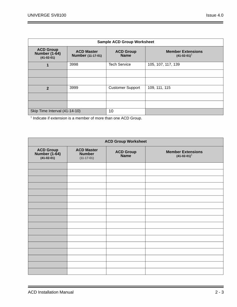
In the ACD Group Worksheet on page 2-3, in the Member Extensions column, enter the member extensions for each ACD Group.
If an extension is a member of more than one ACD Group, ensure that extension is active in only one ACD Group during a particular Work Period. Refer to Assign Extensions for Each Work Period on page 2-7.
The Sample ACD Group Worksheet on page 2-3 shows extensions 105, 107, 117 and 139 in ACD Group 1. Extensions 109, 111 and 115 are shown in ACD Group 2.
2. Choose an ACD Master Number.
The ACD Master Number is the extension number for the ACD Group. Calls transferred to an ACD Master Number enter that ACD Group and are routed to the group member extensions accordingly. Although the master number can be any valid extension number, it is recommended you choose a number that is not in close sequence with those numbers typical for that group of member extensions.
In the ACD Group Worksheet on page 2-3, enter the Master Number for each of the ACD Groups. The sample worksheet below uses 3998 for ACD Group 1 and 3999 for ACD Group 2.
3. Enter an ACD Group Name.
In the ACD Group Worksheet, enter a name for each group. The sample worksheet below uses Tech Service for ACD Group 1 and Customer Support for ACD Group 2.
4. Set the Skip Time.
When a call comes into an ACD Group, it rings each available ACD Agent for a preset time and then routes to the next agent. This preset time is called the Skip Time. The default Skip Time setting is 10 seconds.
In ACD Group 1, for example, a call would ring the ACD Agent at extension 105 before trying the next available extension. If 10 seconds is too long to keep callers waiting, shorten the interval. If you want callers to ring for more than 10 seconds, lengthen the Skip Time interval. Your Skip Time setting is the same for all ACD Groups.
In the ACD Group Worksheet, enter the Skip Time interval. The sample worksheet below uses 10 seconds for the Skip Time.
2 - 2
UNIVERGE SV8100 Issue 4.0
Sample ACD Group Worksheet
ACD Group Number (1-64)
(41-02-01)
ACD MasterNumber (11-17-01)
ACD GroupName
Member Extensions (41-02-01)1
1 3998 Tech Service 105, 107, 117, 139
2 3999 Customer Support 109, 111, 115
Skip Time Interval (41-14-10) 101 Indicate if extension is a member of more than one ACD Group.
ACD Group Worksheet
ACD Group Number (1-64)
(41-02-01)
ACD MasterNumber (11-17-01)
ACD GroupName
Member Extensions (41-02-01)1
ACD Installation Manual 2 - 3
Issue 4.0 UNIVERGE SV8100
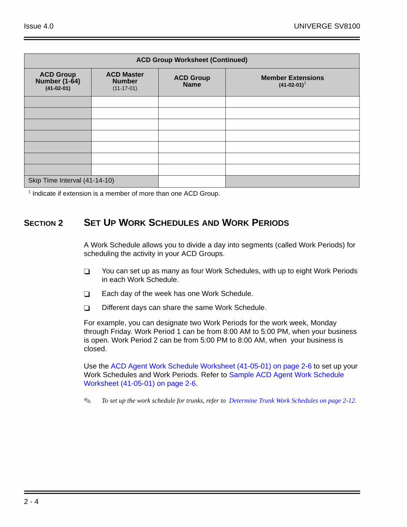
SECTION 2 SET UP WORK SCHEDULES AND WORK PERIODS
A Work Schedule allows you to divide a day into segments (called Work Periods) for scheduling the activity in your ACD Groups.
You can set up as many as four Work Schedules, with up to eight Work Periods in each Work Schedule.
Each day of the week has one Work Schedule.
Different days can share the same Work Schedule.
For example, you can designate two Work Periods for the work week, Monday through Friday. Work Period 1 can be from 8:00 AM to 5:00 PM, when your business is open. Work Period 2 can be from 5:00 PM to 8:00 AM, when your business is closed.
Use the ACD Agent Work Schedule Worksheet (41-05-01) on page 2-6 to set up your Work Schedules and Work Periods. Refer to Sample ACD Agent Work Schedule Worksheet (41-05-01) on page 2-6.
To set up the work schedule for trunks, refer to Determine Trunk Work Schedules on page 2-12.
Skip Time Interval (41-14-10)
1 Indicate if extension is a member of more than one ACD Group.
ACD Group Worksheet (Continued)
ACD Group Number (1-64)
(41-02-01)
ACD MasterNumber (11-17-01)
ACD GroupName
Member Extensions (41-02-01)1
2 - 4
UNIVERGE SV8100 Issue 4.0
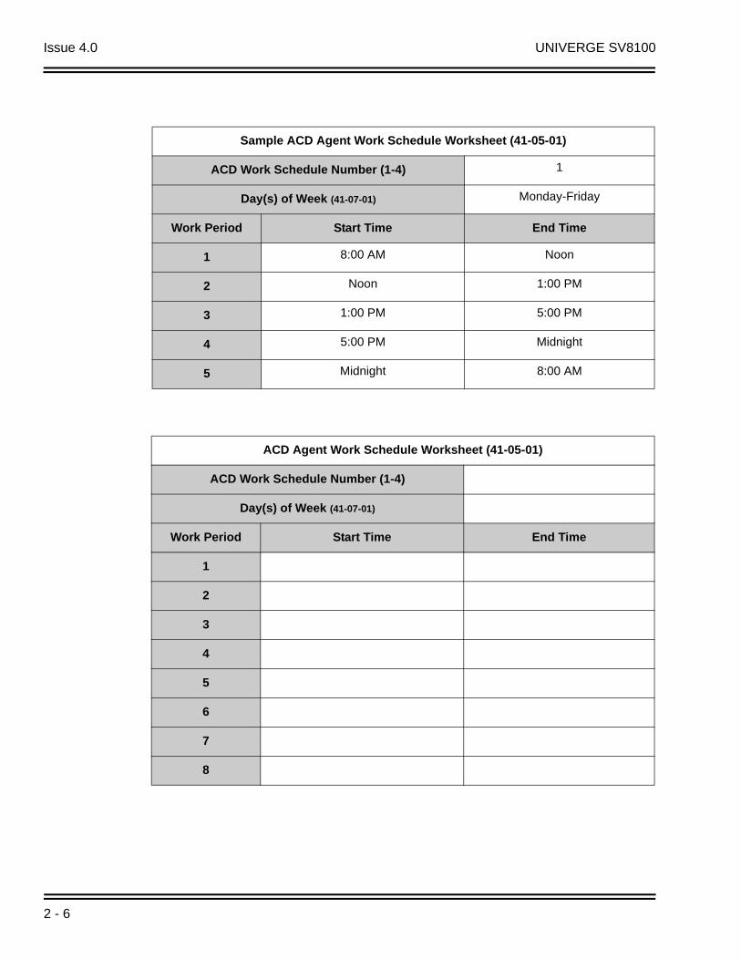
1. Designate a worksheet for each Work Schedule.
Make additional copies of the ACD Agent Work Schedule Worksheet (41-05-01) on page 2-6 so you will have enough for all of your work schedules.
In the upper right corner of each worksheet, write the number of the corresponding work schedule.
2. Assign Days of the Week to each Work Schedule.
In the Day(s) of Week row of each worksheet, indicate which days of the week to use the Work Schedule. The sample worksheet is for Monday through Friday.
3. Set the start and stop time of each work Period.
Enter a start and stop time for each Work Period. Keep in mind that if you leave holes in your Work Schedule, there will be periods during the day when no ACD service is available. Try to accommodate the typical divisions of time during the day. For example, the sample worksheet below shows five Work Periods corresponding to mornings (1), lunch (2), afternoons (3), evenings (4) and late night (5).
ACD Installation Manual 2 - 5
Issue 4.0 UNIVERGE SV8100
Sample ACD Agent Work Schedule Worksheet (41-05-01)
ACD Work Schedule Number (1-4) 1
Day(s) of Week (41-07-01) Monday-Friday
Work Period Start Time End Time
1 8:00 AM Noon
2 Noon 1:00 PM
3 1:00 PM 5:00 PM
4 5:00 PM Midnight
5 Midnight 8:00 AM
ACD Agent Work Schedule Worksheet (41-05-01)
ACD Work Schedule Number (1-4)
Day(s) of Week (41-07-01)
Work Period Start Time End Time
1
2
3
4
5
6
7
8
2 - 6
UNIVERGE SV8100 Issue 4.0
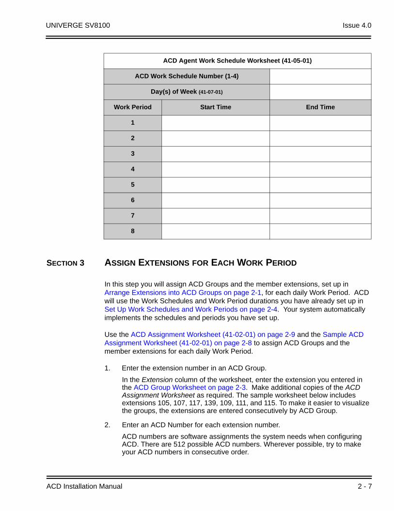
SECTION 3 ASSIGN EXTENSIONS FOR EACH WORK PERIOD
In this step you will assign ACD Groups and the member extensions, set up in Arrange Extensions into ACD Groups on page 2-1, for each daily Work Period. ACD will use the Work Schedules and Work Period durations you have already set up in Set Up Work Schedules and Work Periods on page 2-4. Your system automatically implements the schedules and periods you have set up.
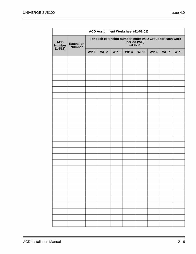
Use the ACD Assignment Worksheet (41-02-01) on page 2-9 and the Sample ACD Assignment Worksheet (41-02-01) on page 2-8 to assign ACD Groups and the member extensions for each daily Work Period.
1. Enter the extension number in an ACD Group.
In the Extension column of the worksheet, enter the extension you entered in the ACD Group Worksheet on page 2-3. Make additional copies of the ACD Assignment Worksheet as required. The sample worksheet below includes extensions 105, 107, 117, 139, 109, 111, and 115. To make it easier to visualize the groups, the extensions are entered consecutively by ACD Group.
2. Enter an ACD Number for each extension number.
ACD numbers are software assignments the system needs when configuring ACD. There are 512 possible ACD numbers. Wherever possible, try to make your ACD numbers in consecutive order.
ACD Agent Work Schedule Worksheet (41-05-01)
ACD Work Schedule Number (1-4)
Day(s) of Week (41-07-01)
Work Period Start Time End Time
1
2
3
4
5
6
7
8
ACD Installation Manual 2 - 7
Issue 4.0 UNIVERGE SV8100
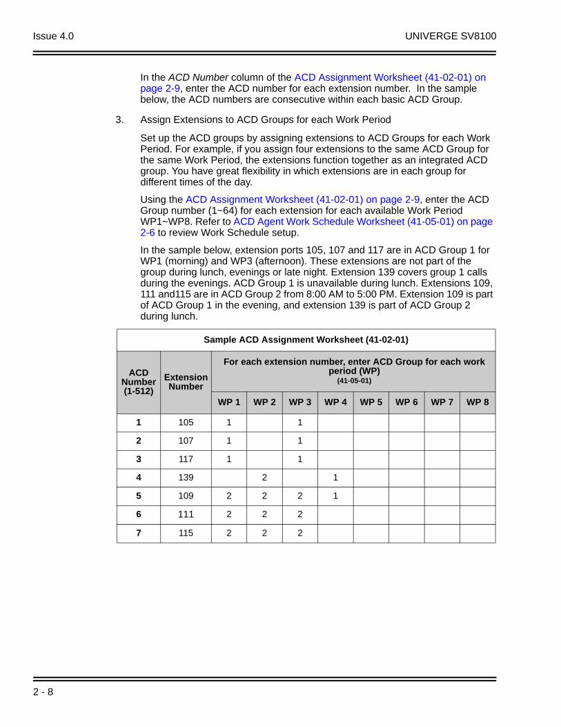
In the ACD Number column of the ACD Assignment Worksheet (41-02-01) on page 2-9, enter the ACD number for each extension number. In the sample below, the ACD numbers are consecutive within each basic ACD Group.
3. Assign Extensions to ACD Groups for each Work Period
Set up the ACD groups by assigning extensions to ACD Groups for each Work Period. For example, if you assign four extensions to the same ACD Group for the same Work Period, the extensions function together as an integrated ACD group. You have great flexibility in which extensions are in each group for different times of the day.
Using the ACD Assignment Worksheet (41-02-01) on page 2-9, enter the ACD Group number (1~64) for each extension for each available Work Period WP1~WP8. Refer to ACD Agent Work Schedule Worksheet (41-05-01) on page 2-6 to review Work Schedule setup.
In the sample below, extension ports 105, 107 and 117 are in ACD Group 1 for WP1 (morning) and WP3 (afternoon). These extensions are not part of the group during lunch, evenings or late night. Extension 139 covers group 1 calls during the evenings. ACD Group 1 is unavailable during lunch. Extensions 109, 111 and115 are in ACD Group 2 from 8:00 AM to 5:00 PM. Extension 109 is part of ACD Group 1 in the evening, and extension 139 is part of ACD Group 2 during lunch.
Sample ACD Assignment Worksheet (41-02-01)
ACDNumber(1-512)
Extension Number
For each extension number, enter ACD Group for each work period (WP)
(41-05-01)
WP 1 WP 2 WP 3 WP 4 WP 5 WP 6 WP 7 WP 8
1 105 1 1
2 107 1 1
3 117 1 1
4 139 2 1
5 109 2 2 2 1
6 111 2 2 2
7 115 2 2 2
2 - 8
UNIVERGE SV8100 Issue 4.0
ACD Assignment Worksheet (41-02-01)
ACDNumber(1-512)
Extension Number
For each extension number, enter ACD Group for each work period (WP)
(41-05-01)
WP 1 WP 2 WP 3 WP 4 WP 5 WP 6 WP 7 WP 8
ACD Installation Manual 2 - 9
Issue 4.0 UNIVERGE SV8100
SECTION 4 ARRANGE TRUNKS INTO INCOMING RING GROUPS
ACD can be set to automatically answer incoming calls.
Incoming trunk calls can automatically route to specific ACD Group (200 trunks ports and 100 Ring groups are available). These types of calls ring directly into the ACD Group without being transferred by a co-worker or the Automated Attendant. Calls can route directly to ACD:
Assign the trunk to an Incoming Trunk Ring Group (in this section).
Set up the trunk work schedules (Refer to Determine Trunk Work Schedules on page 2-12.)
Assign Incoming Ring Groups to ACD Groups (Refer to Assign Incoming Trunk Ring Groups to ACD Groups on page 2-14.)
DISA, DID and tie trunks can ring an ACD master number directly.
Use the ACD Incoming Trunk Ring Group Worksheet (22-05-01) on page 2-11 and the sample below when completing this step.
1. Determine which trunks you want answered by ACD Groups.
In the Trunk Port column of the worksheet, enter the number of each trunk you want ACD to automatically answer. In the example below, trunks 1 and 2 will be automatically answered by ACD.
2. Assign the trunk ports to Incoming Ring Groups.
In the Incoming Ring Group columns, enter the Incoming Trunk Ring Group for each trunk port, for each Night Service mode. Trunks that have the same basic function and that will be assigned the same priority in Assign Incoming Trunk Ring Groups to ACD Groups on page 2-14 should be in the same incoming Ring Group.
For example, if you have trunks 1~4 that will be primarily answered by the same ACD Group, put trunks 1~4 in the same incoming group.
You can mix assignments if the trunks have different functions during the different Night Service modes.) In the example below, trunk 1 is in incoming group 2, while trunk 2 is in incoming group 3.
Assign Incoming Trunk Ring Groups to ACD Groups on page 2-14 sets the Incoming Trunk Ring Group priority. Priority groups always have precedence over normal groups.
For example, if a call from a priority group rings in when while a normal group call is already ringing, ACD services the priority call first. ACD services multiple priority calls on a first-come, first-served basis. Keep this in mind when assigning the trunk ports to incoming Ring Groups.
2 - 10

UNIVERGE SV8100 Issue 4.0
Sample ACD Incoming Trunk Ring Group Worksheet (22-05-01)
Trunk Number
Incoming Ring Group
Day Night Rest Midnight Day 2 Night 2 Rest 2 Midnight 2
1 2 2 2 2
2 3 3 3 3
ACD Incoming Trunk Ring Group Worksheet (22-05-01)
Trunk Number
Incoming Ring Group
Day Night Rest Midnight Day 2 Night 2 Rest 2 Midnight 2
ACD Installation Manual 2 - 11

Issue 4.0 UNIVERGE SV8100
SECTION 5 DETERMINE TRUNK WORK SCHEDULES
Trunk Work Schedules are similar to normal ACD Work Schedules except that they apply only to trunks assigned to ACD groups. Refer to Assign Incoming Trunk Ring Groups to ACD Groups on page 2-14. The Trunk Work Schedule allows you to divide a day into segments (called Work Periods) to determine when trunks route to ACD Groups. You can set as many as four Work Schedules, with up to eight Work Periods in each Work Schedule. Each day of the week has one Trunk Work Schedule, but different days can share the same schedule.
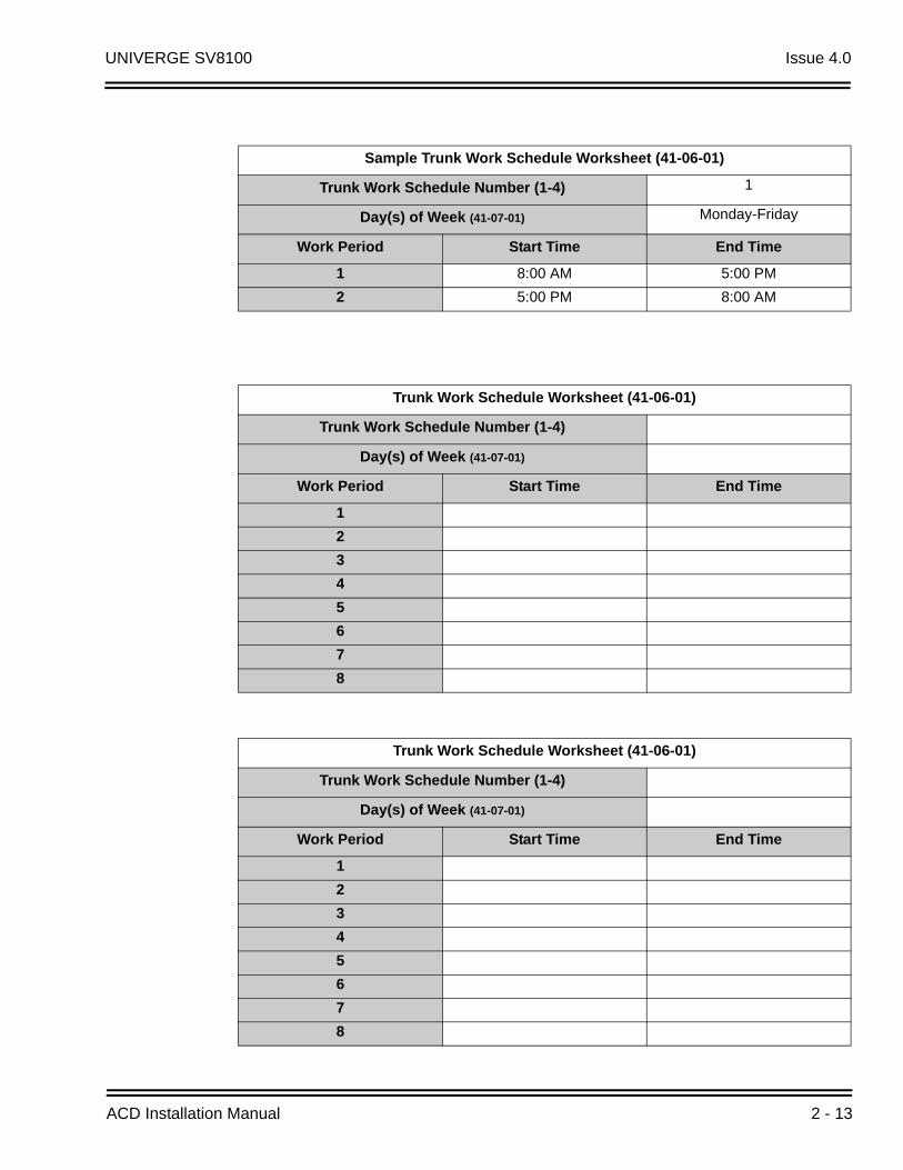
For example, Monday-Friday can have the same daily schedule where Work Period 1 lasts from 8:00 AM to 5:00 PM. Saturday can have a Work Period 1 lasting from 8:00 AM to 1:00 PM. Use the Trunk Work Schedule Worksheet (41-06-01) on page 2-13 and the sample below to set up Trunk Work Schedules.
1. Designate a worksheet for each Trunk Work Schedule.
Make additional copies of the Trunk Work Schedule Worksheet (41-06-01) on page 2-13 so you will have one worksheet for each Work Schedule.
In the upper right corner of each worksheet, write the number of the corresponding Trunk Work Schedule (1~8). The sample worksheet below is for Trunk Work Schedule 1.
2. Assign Days of the week to each Work Schedule.
The day of the week assignment for each Trunk Work Schedule must correspond to the weekday assignments made in Set Up Work Schedules and Work Periods on page 2-4. For example, if Work Schedule 1 is set for Monday through Friday in Set Up Work Schedules and Work Periods on page 2-4, that assignment must be reflected in the Trunk Work Schedule.
3. Set the start and stop time of each work period.
Enter a start and stop time for each Work Period. Keep in mind that if you leave holes in your Work Schedule there will be periods during the day when the trunk does not ring the ACD Group. Also, try to accommodate the typical divisions of time periods during the day. For example, the sample worksheet below shows two Work Periods corresponding to day (1) and night (2).
2 - 12
UNIVERGE SV8100 Issue 4.0
Sample Trunk Work Schedule Worksheet (41-06-01)
Trunk Work Schedule Number (1-4) 1
Day(s) of Week (41-07-01) Monday-Friday
Work Period Start Time End Time
1 8:00 AM 5:00 PM
2 5:00 PM 8:00 AM
Trunk Work Schedule Worksheet (41-06-01)
Trunk Work Schedule Number (1-4)
Day(s) of Week (41-07-01)
Work Period Start Time End Time
1
2
3
4
5
6
7
8
Trunk Work Schedule Worksheet (41-06-01)
Trunk Work Schedule Number (1-4)
Day(s) of Week (41-07-01)
Work Period Start Time End Time
1
2
3
4
5
6
7
8
ACD Installation Manual 2 - 13

Issue 4.0 UNIVERGE SV8100
SECTION 6 ASSIGN INCOMING TRUNK RING GROUPS TO ACD GROUPS
This section explains how to customize Trunk Ring ACD Groups for each Work Period. You will assign Incoming Trunk Ring Groups to ACD Groups for each daily Work Period. If a trunk within the incoming group is assigned to an ACD Group, incoming calls on that trunk directly ring the first available ACD agent. The system always knows the day of the week, so ACD can implement the schedules and periods you program automatically. Use the ACD Incoming Trunk Ring Group Assignment Worksheet (41-03-xx) on page 2-16 and the sample below when completing this step.
There are 100 Ring Groups, eight Work Periods and 64 ACD Groups.
You can assign whether the night announcement is used for the ring group. The night announcement function is not available for ACD pilot number calls.
Set the Incoming Trunk Ring Group priority. Priority groups always have precedence over normal groups. For example, if a call from a priority group rings in when while a normal group call is already ringing, ACD services the priority call first. ACD services multiple priority calls on a first-come, first-served basis.
1. Select the Incoming Trunk Ring Group you want to program.
In the Incoming Trunk Ring Group field at the top of the worksheet, enter the number of the incoming group you are programming. To see which trunks you assigned to the ring group, refer to Determine Trunk Work Schedules on page 2-12. The sample worksheets on the next page are for Incoming Ring Groups 2 and 3.
2. Enter the Incoming Trunk Ring Group for each Work Period.
In the ACD column for each Work Period, enter the number of the ACD group (1~64) that will answer the Incoming Ring Group calls. Only one ACD Group can answer an Incoming Ring Group calls during any single Work Period. In the sample worksheet on the next page for Ring Group 2, for example, Incoming Trunk Ring Group 1 rings into ACD Group 1 during Work Periods 1 and 3. It rings into ACD Group 2 during Work Period 2.
3. Set whether or not the Incoming Trunk Ring Group entered in the previous step should play the Night Announcement.
Select whether the Incoming Trunk Ring Group should have the Night Announcement enabled. Night Announcement used is selected from either an ACI port or the VRS.
4. Set the priority of the Incoming Trunk Ring Group being defined.
Set the Incoming Trunk Ring Group for Priority or Normal operation. Priority Ring Groups have precedence over Normal Ring Groups. For example, if a normal trunk is already ringing an ACD group when a priority trunk rings in, the new call starts ringing and the normal trunk waits in queue behind it. Two priority trunks ringing at the same time will ring the ACD Group on a first-come, first-served basis.
2 - 14

UNIVERGE SV8100 Issue 4.0
Sample ACD Incoming Trunk Ring Group Assignment Worksheet (41-03-xx)
Incoming Trunk Ring Group (22-05-01) 2
For each work period (WP 1-8) enter:
ACD ACD Group that should answer the Incoming Ring Group trunks(ACD Groups: 1-64) (41-03-01)
N Night Announcements (0 = Disable, 1 = Enable) (41-03-02)
P Trunk priority (0 = Normal, 1 ~ 9 = Priority)(41-03-03)
WP1 WP2 WP3 WP4
ACD N P ACD N P ACD N P ACD N P
1 1 1 2 1 0 1 0 0
WP5 WP6 WP7 WP8
ACD N P ACD N P ACD N P ACD N P
Work periods use the same Work Schedules as ACD Agents. See ACD Agent Work Schedule Worksheet (41-05-01) on page 2-6.
Sample ACD Incoming Trunk Ring Group Assignment Worksheet (41-03-xx)
Incoming Trunk Ring Group (22-05-01) 3
For each work period (WP 1-8) enter:
ACD ACD Group that should answer the Incoming Ring Group trunks(ACD Groups: 1-64) (41-03-01)
N Night Announcements (0 = Disable, 1 = Enable) (41-03-02)
P Trunk priority (0 = Normal, 1 ~ 9 = Priority)(41-03-03)
WP1 WP2 WP3 WP4
ACD N P ACD N P ACD N P ACD N P
2 1 1 1 1 0 2 0 0
WP5 WP6 WP7 WP8
ACD N P ACD N P ACD N P ACD N P
Work periods use the same Work Schedules as ACD Agents. See ACD Agent Work Schedule Worksheet (41-05-01) on page 2-6.
ACD Installation Manual 2 - 15

Issue 4.0 UNIVERGE SV8100
ACD Incoming Trunk Ring Group Assignment Worksheet (41-03-xx)
Incoming Trunk Ring Group (22-05-01)
For each work period (WP 1-8) enter:
ACD ACD Group that should answer the Incoming Ring Group trunks(ACD Groups: 1-64) (41-03-01)
N Night Announcements (0 = Disable, 1 = Enable) (41-03-02)
P Trunk priority (0 = Normal, 1 ~ 9 = Priority)(41-03-03)
WP1 WP2 WP3 WP4
ACD N P ACD N P ACD N P ACD N P
WP5 WP6 WP7 WP8
ACD N P ACD N P ACD N P ACD N P
Work periods use the same Work Schedules as ACD Agents. See ACD Agent Work Schedule Worksheet (41-05-01) on page 2-6.
2 - 16
UNIVERGE SV8100 Issue 4.0
SECTION 7 BASIC PROGRAMMING
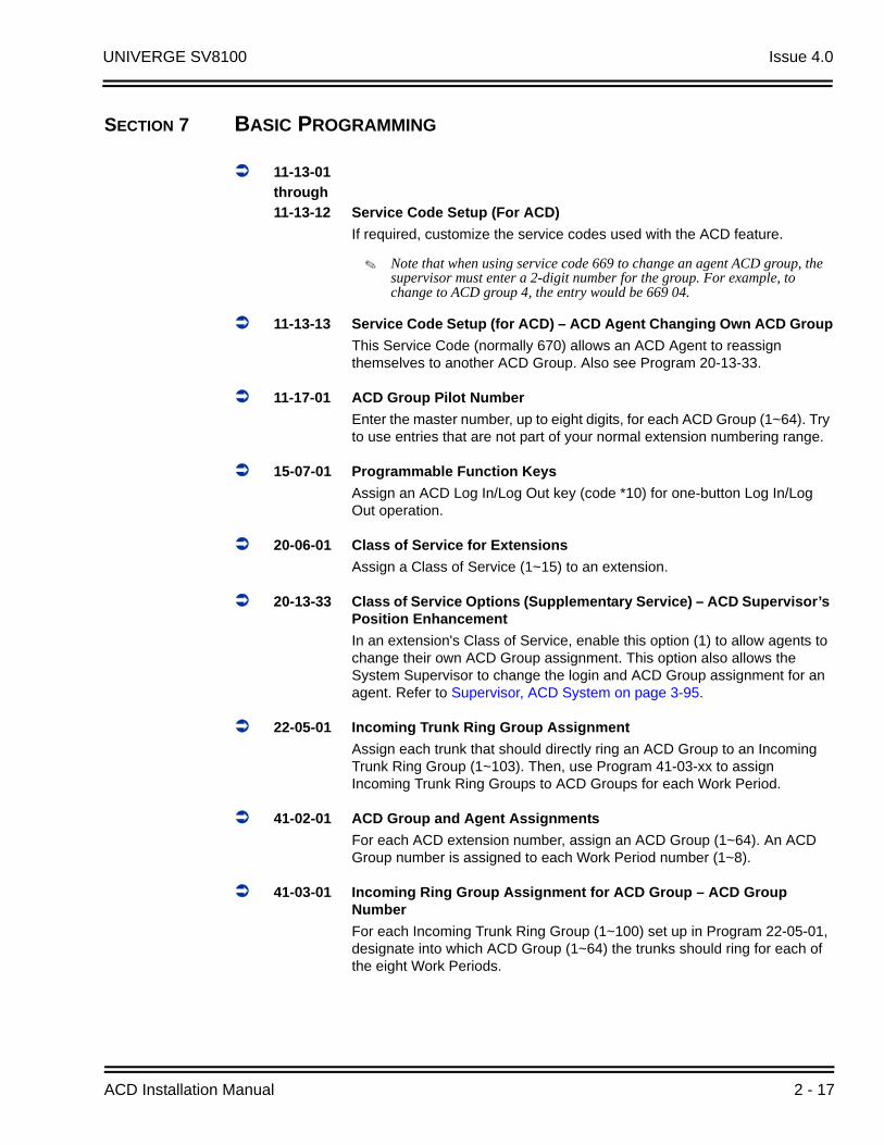
11-13-01
through
11-13-12 Service Code Setup (For ACD)
If required, customize the service codes used with the ACD feature.
Note that when using service code 669 to change an agent ACD group, the supervisor must enter a 2-digit number for the group. For example, to change to ACD group 4, the entry would be 669 04.
11-13-13 Service Code Setup (for ACD) – ACD Agent Changing Own ACD Group
This Service Code (normally 670) allows an ACD Agent to reassign themselves to another ACD Group. Also see Program 20-13-33.
11-17-01 ACD Group Pilot Number
Enter the master number, up to eight digits, for each ACD Group (1~64). Try to use entries that are not part of your normal extension numbering range.
15-07-01 Programmable Function Keys
Assign an ACD Log In/Log Out key (code *10) for one-button Log In/Log Out operation.
20-06-01 Class of Service for Extensions
Assign a Class of Service (1~15) to an extension.
20-13-33 Class of Service Options (Supplementary Service) – ACD Supervisor’s Position Enhancement
In an extension's Class of Service, enable this option (1) to allow agents to change their own ACD Group assignment. This option also allows the System Supervisor to change the login and ACD Group assignment for an agent. Refer to Supervisor, ACD System on page 3-95.
22-05-01 Incoming Trunk Ring Group Assignment
Assign each trunk that should directly ring an ACD Group to an Incoming Trunk Ring Group (1~103). Then, use Program 41-03-xx to assign Incoming Trunk Ring Groups to ACD Groups for each Work Period.
41-02-01 ACD Group and Agent Assignments
For each ACD extension number, assign an ACD Group (1~64). An ACD Group number is assigned to each Work Period number (1~8).
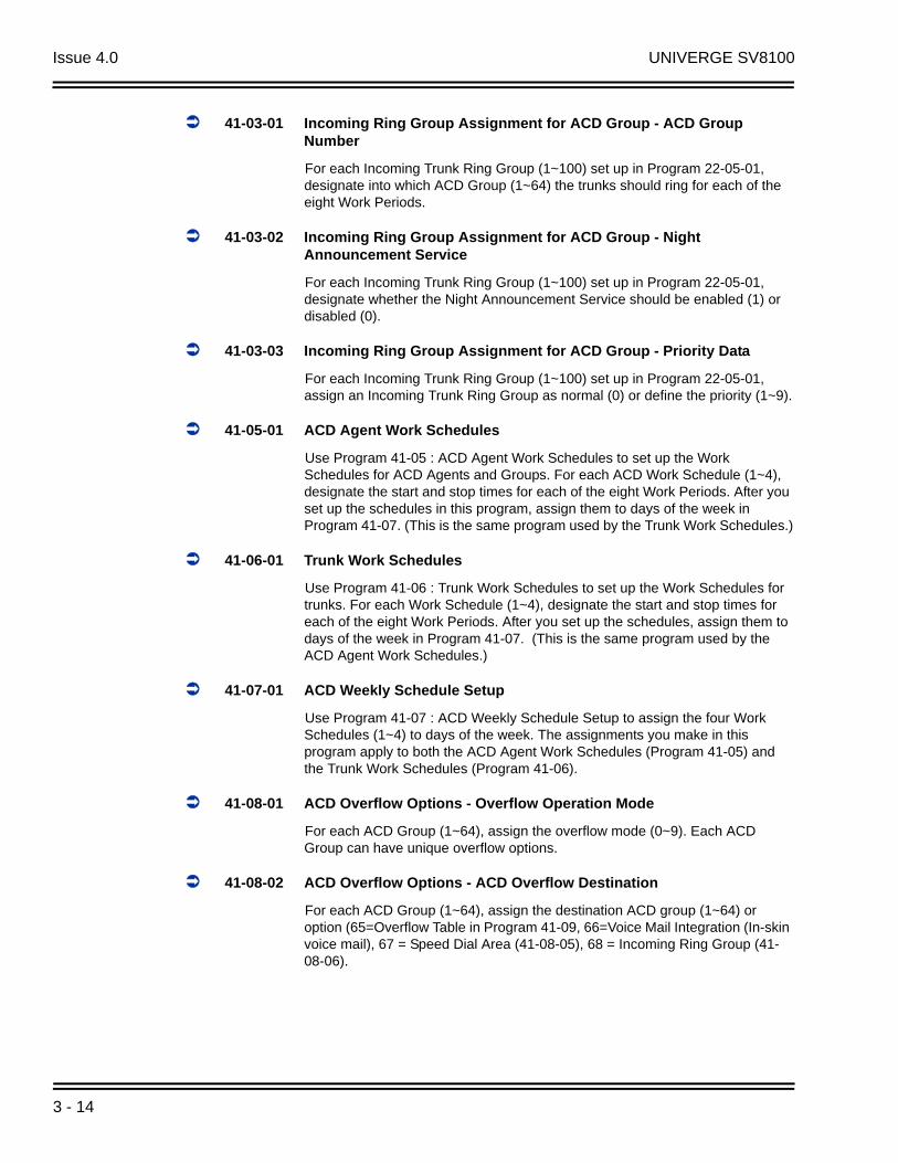
41-03-01 Incoming Ring Group Assignment for ACD Group – ACD Group Number
For each Incoming Trunk Ring Group (1~100) set up in Program 22-05-01, designate into which ACD Group (1~64) the trunks should ring for each of the eight Work Periods.
ACD Installation Manual 2 - 17
Issue 4.0 UNIVERGE SV8100
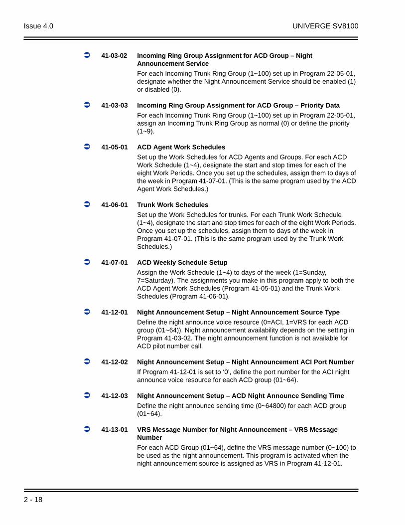
41-03-02 Incoming Ring Group Assignment for ACD Group – Night Announcement Service
For each Incoming Trunk Ring Group (1~100) set up in Program 22-05-01, designate whether the Night Announcement Service should be enabled (1) or disabled (0).
41-03-03 Incoming Ring Group Assignment for ACD Group – Priority Data
For each Incoming Trunk Ring Group (1~100) set up in Program 22-05-01, assign an Incoming Trunk Ring Group as normal (0) or define the priority (1~9).
41-05-01 ACD Agent Work Schedules
Set up the Work Schedules for ACD Agents and Groups. For each ACD Work Schedule (1~4), designate the start and stop times for each of the eight Work Periods. Once you set up the schedules, assign them to days of the week in Program 41-07-01. (This is the same program used by the ACD Agent Work Schedules.)
41-06-01 Trunk Work Schedules
Set up the Work Schedules for trunks. For each Trunk Work Schedule (1~4), designate the start and stop times for each of the eight Work Periods. Once you set up the schedules, assign them to days of the week in Program 41-07-01. (This is the same program used by the Trunk Work Schedules.)
41-07-01 ACD Weekly Schedule Setup
Assign the Work Schedule (1~4) to days of the week (1=Sunday, 7=Saturday). The assignments you make in this program apply to both the ACD Agent Work Schedules (Program 41-05-01) and the Trunk Work Schedules (Program 41-06-01).
41-12-01 Night Announcement Setup – Night Announcement Source Type
Define the night announce voice resource (0=ACI, 1=VRS for each ACD group (01~64)). Night announcement availability depends on the setting in Program 41-03-02. The night announcement function is not available for ACD pilot number call.
41-12-02 Night Announcement Setup – Night Announcement ACI Port Number
If Program 41-12-01 is set to ‘0’, define the port number for the ACI night announce voice resource for each ACD group (01~64).
41-12-03 Night Announcement Setup – ACD Night Announce Sending Time
Define the night announce sending time (0~64800) for each ACD group (01~64).
41-13-01 VRS Message Number for Night Announcement – VRS Message Number
For each ACD Group (01~64), define the VRS message number (0~100) to be used as the night announcement. This program is activated when the night announcement source is assigned as VRS in Program 41-12-01.
2 - 18

UNIVERGE SV8100 Issue 4.0
41-13-02 VRS Message Number for Night Announcement – Tone Kind at Message Interval
For each ACD Group (01~64), define the what the caller will hear between the night announcements (0=Ring Back Tone, 1=MOH Tone, 2=BGM Source).
41-14-10 ACD Options Setup – ACD No Answer Skip Time
For each ACD Group (01~64), set how long the system waits before transferring an unanswered call to the next ACD agent (0=disabled or 1~64800 seconds). This timer is also used to determine when an unanswered call is transferred to the Group Supervisor if Program 41-04-01 is set to 1 or 2.
Default Setting
ACD is not set up.
SECTION 8 BASIC OPERATIONS
8.1 Transferring Calls to an ACD Group
To Transfer a call to an ACD Group:
1. At the multiline telephone, press the Transfer key.
- OR -
At single line telephone, hookflash.
You hear Transfer dial tone.
2. Dial ACD Group Master number.
You can press a One-Touch Key for the master instead.
3. Hang up.
ACD Installation Manual 2 - 19
Issue 4.0 UNIVERGE SV8100
8.2 Answering Outside Calls that Ring Your ACD Group
To answer an outside call that rings your ACD Group:
DISA, DID and tie trunks can ring an ACD master number directly.
Refer to Arrange Trunks Into Incoming Ring Groups on page 2-10, Determine Trunk Work Schedules on page 2-12 and Assign Incoming Trunk Ring Groups to ACD Groups on page 2-14 for information on setting up other trunk types to ring ACD Groups. Trunks can also be transferred to ACD master numbers.
1. Lift handset.
2. If you don't automatically answer the call, press the flashing line key.
8.3 Agent Log In and Log Out
To log your extension into the ACD Group:
Multiline
Your display shows: WAIT ACD LOGIN. If Program 12-07-01 has a customized Day/Night mode message defined, the ACD agent’s display will not indicate the WAIT ACD LOGIN status (however, the agent may still log in using the following procedure).
1. Press the Speaker key.
2. Dial 5.
You hear confirmation tone.
- OR -
Press ACD Log On/Off key (PGM 15-07-01 or SC 752: code *10).
You hear a single beep.
Your display will show the ACD Group to which you are logged in. If your system has ACD Identification Codes enabled, enter it now. Refer to Identification Codes for ACD Agents on page 3-45.
Single Line Telephone
1. Lift handset.
2. Dial 5.
You hear confirmation tone.
If your system has ACD Identification Codes enabled, enter it now. Refer to Identification Codes for ACD Agents on page 3-45.
2 - 20
UNIVERGE SV8100 Issue 4.0
To log your extension out of an ACD Group:
Multiline
Your display shows the ACD Group where you are logged in.
1. Press the Speaker key.
2. Dial 5.
- OR -
Press ACD Log On/Off key (PGM 15-07-01 or SC 752: code *10).
Your display shows: ACD LOGOUT (1:Yes, 0:No)
3. Dial 1 to log out.
You hear confirmation tone (if you dialed *5) or a single beep (if you pressed the ACD Log On/Log Off key.
- OR -
Dial 0 to cancel the log out and return to the group.
Single Line Telephone
1. Lift handset.
2. Dial 655.
8.4 Changing ACD Group Assignment
To change your ACD Group Assignment:
1. Log out of your ACD Group. Refer to Agent Log In and Log Out on page 2-20.
2. Press the Speaker key.
3. Dial 670.
4. Dial the number of the new ACD Group (1~64) you are logging into.
You hear confirmation tone.
5. Log into the new ACD Group. Refer to Agent Log In and Log Out on page 2-20.
ACD Installation Manual 2 - 21

Issue 4.0 UNIVERGE SV8100
THIS PAGE INTENTIONALLY LEFT BLANK
2 - 22
Ad
van
ce
d A
CD
Featu
res
3
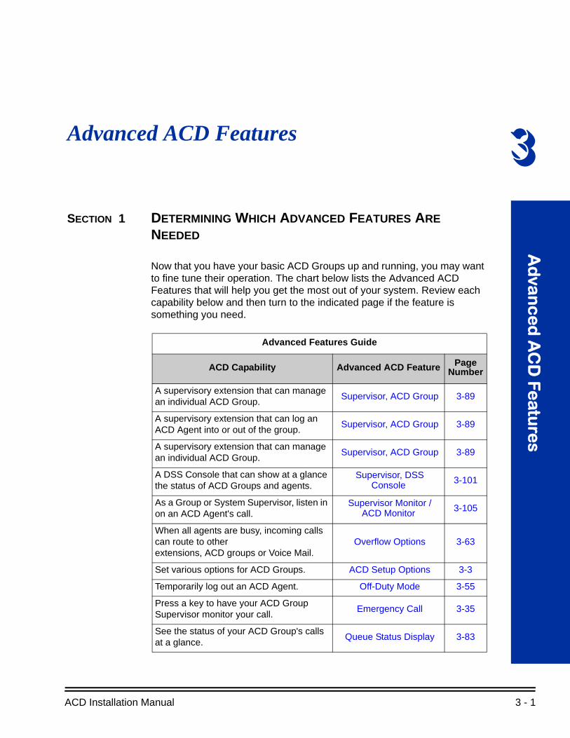
Advanced ACD FeaturesSECTION 1 DETERMINING WHICH ADVANCED FEATURES ARE NEEDED
Now that you have your basic ACD Groups up and running, you may want to fine tune their operation. The chart below lists the Advanced ACD Features that will help you get the most out of your system. Review each capability below and then turn to the indicated page if the feature is something you need.
Advanced Features Guide
ACD Capability Advanced ACD Feature Page Number
A supervisory extension that can manage an individual ACD Group.
Supervisor, ACD Group 3-89
A supervisory extension that can log an ACD Agent into or out of the group.
Supervisor, ACD Group 3-89
A supervisory extension that can manage an individual ACD Group.
Supervisor, ACD Group 3-89
A DSS Console that can show at a glance the status of ACD Groups and agents.
Supervisor, DSS Console 3-101
As a Group or System Supervisor, listen in on an ACD Agent's call.
Supervisor Monitor / ACD Monitor 3-105
When all agents are busy, incoming calls can route to other extensions, ACD groups or Voice Mail.
Overflow Options 3-63
Set various options for ACD Groups. ACD Setup Options 3-3
Temporarily log out an ACD Agent. Off-Duty Mode 3-55
Press a key to have your ACD Group Supervisor monitor your call.
Emergency Call 3-35
See the status of your ACD Group's calls at a glance.
Queue Status Display 3-83
ACD Installation Manual 3 - 1

Issue 4.0 UNIVERGE SV8100
Set up SIE keys for ACD Groups. SIE Key for ACD Groups 3-51
Get one-button ACD Group calling and Transfer as well as a unique BLF for ACD agents.
Hotline for ACD Agents 3-41
Temporarily busy out your phone to the ACD Group when you need to work at your desk.
Wrap-Up Time 3-111
Use a headset for privacy and convenience, and optionally answer calls automatically.
Headset Operation (with Automatic Answer) 3-39
For systems with UNIVERGE SV8100 ACD MIS installed, allow Reports and Monitor to sort based on ACD Agent number.Set up AIC log-in for specific agents using a verified code. This also allows for multiple group log-ins by an agent.
Identification Codes for ACD Agents 3-45
Analyze system usage and calling patterns.
Traffic Reports 3-107
A caller can press a One-Digit Dial Out option to dial out of Queue.
One-Digit Dial Out 3-59
Route ACD Calls based on an Agent’s skill level.
ACD Skill Based Routing 3-7
Advanced Features Guide (Continued)
ACD Capability Advanced ACD Feature Page Number
3 - 2
UNIVERGE SV8100 Issue 4.0
ACD Setup Options
Description
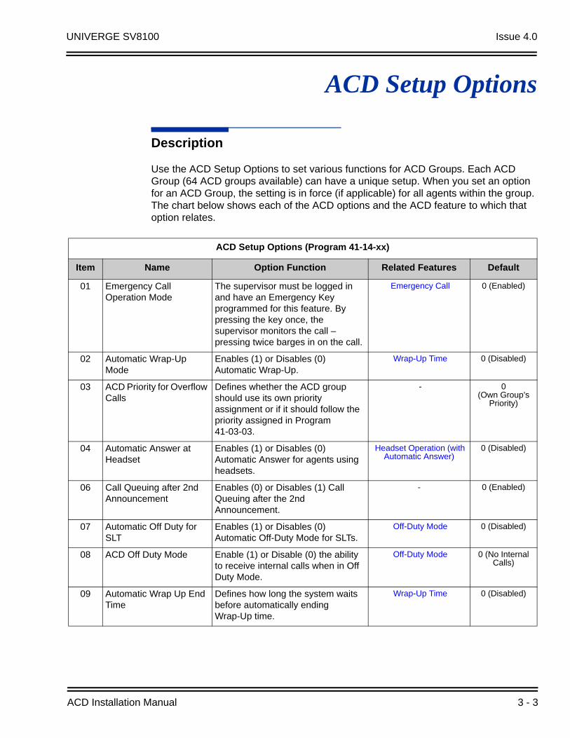
Use the ACD Setup Options to set various functions for ACD Groups. Each ACD Group (64 ACD groups available) can have a unique setup. When you set an option for an ACD Group, the setting is in force (if applicable) for all agents within the group. The chart below shows each of the ACD options and the ACD feature to which that option relates.
ACD Setup Options (Program 41-14-xx)
Item Name Option Function Related Features Default
01 Emergency Call Operation Mode
The supervisor must be logged in and have an Emergency Key programmed for this feature. By pressing the key once, the supervisor monitors the call – pressing twice barges in on the call.
Emergency Call 0 (Enabled)
02 Automatic Wrap-Up Mode
Enables (1) or Disables (0) Automatic Wrap-Up.
Wrap-Up Time 0 (Disabled)
03 ACD Priority for Overflow Calls
Defines whether the ACD group should use its own priority assignment or if it should follow the priority assigned in Program 41-03-03.
- 0 (Own Group’s
Priority)
04 Automatic Answer at Headset
Enables (1) or Disables (0) Automatic Answer for agents using headsets.
Headset Operation (with Automatic Answer)
0 (Disabled)
06 Call Queuing after 2nd Announcement
Enables (0) or Disables (1) Call Queuing after the 2nd Announcement.
- 0 (Enabled)
07 Automatic Off Duty for SLT
Enables (1) or Disables (0) Automatic Off-Duty Mode for SLTs.
Off-Duty Mode 0 (Disabled)
08 ACD Off Duty Mode Enable (1) or Disable (0) the ability to receive internal calls when in Off Duty Mode.
Off-Duty Mode 0 (No Internal Calls)
09 Automatic Wrap Up End Time
Defines how long the system waits before automatically ending Wrap-Up time.
Wrap-Up Time 0 (Disabled)
ACD Installation Manual 3 - 3

Issue 4.0 UNIVERGE SV8100
Conditions
None
Default Setting
Refer to ACD Setup Options (Program 41-14-xx) on page 3-3.
Programming
41-14-01
through
41-14-15 ACD Options Setup
Set various options for each ACD Group. Refer to ACD Setup Options (Program 41-14-xx) on page 3-3.
10 ACD No Answer Skip Time
Sets how long a call into an ACD Group will ring an idle extension before routing to the next agent.
- 10 Seconds
12 Start Headset Ear Piece Ringing (for SLT)
- - 0
13 1st Data – ACD Queue 1-Digit Assignment
- - Blank
2nd Data – Destination Number Type
- - 0
3rd Data – Destination Number
- - Blank
14 DTMF Detection Assignment during Delay Announcement
Is the DTMF Detection for Dial Out during (1) or after (0) the message is played
- 1
15 DTMF Detect Time after Delay Announcement Message
How long is the DTMF Detection after the Delay Announcement Message.
- 0
ACD Setup Options (Program 41-14-xx) (Continued)
Item Name Option Function Related Features Default
3 - 4
UNIVERGE SV8100 Issue 4.0
Related Features
Class of Service
Operation
Refer to ACD Setup Options (Program 41-14-xx) on page 3-3.
ACD Installation Manual 3 - 5

Issue 4.0 UNIVERGE SV8100
THIS PAGE INTENTIONALLY LEFT BLANK
3 - 6

UNIVERGE SV8100 Issue 4.0
ACD Skill Based Routing
Description
The SV8100 can distribute ACD calls based on the Agent’s skill level when it receives ACD Calls. There are seven priority levels that the Agents can be set to for each ACD Queue. Each queue can have a different priority level. This will work for both AIC and Normal Agents. The skill levels are based on the Login ID that the Agents use. This requires both the Version 5000 Enhancement license and the ACD Skill Based Routing license.
Normal Login Mode
This section describes the skill level assignment for each agent in Normal Login Mode.
Ext 101
Login ID: 1010
Ext 102
Login ID: 1011
Ext 103
Login ID: 1012
Mode Assignment (PRG 41-05-01)
Mode 1 8:30~12:00
Mode 2 13:00~17:30
ACD Group Assignment (PRG 41-02-XX)
Mode 1 Mode 2 --- Mode 8
Ext 101 Group 1 Group 1 --- 0
Ext 102 0 Group 1 --- 0
Ext 103 Group 1 Group 2 --- 0
Login ID to Skill Table (PRG 41-21-01&02)
Login ID Skill Table
1010 Table 1
1011 Table 2
1012 Table 3
Skill Table (PRG 41-23-01)
Group 1 Group 2 --- Mode 64
Table 1 Level 1 Level 1 --- Level 1
Table 2 Level 2 Level 1 --- Level 1
Table 3 Level 2 Level 1 --- Level 1
ACD Installation Manual 3 - 7

Issue 4.0 UNIVERGE SV8100
ACD Group and Skill Assignment for each Agent :
Time Schedule ACD Group Assignment
Ext 101
8:30 ~ 12:00 ACD Group 1, Level 1
13:00 ~ 17:30 ACD Group 1, Level 1
Other time Non-ACD Agent
Ext 102
8:30 ~ 12:00 Non-ACD Agent
13:00 ~ 17:30 ACD Group 1, Level 2
Other time Non-ACD Agent
Ext 103
8:30 ~ 12:00 ACD Group 1, Level 2
13:00 ~ 17:30 ACD Group 2, Level 1
Other time Non-ACD Agent
3 - 8

UNIVERGE SV8100 Issue 4.0
Login ID is not Assigned a Skill Level
If Login ID is not registered to the System Data and/or is registered, but the Skill Table is not assigned, then the system treats the agent as a highest level (level 1).
ACD Group and Skill Assignment for each Agent:
Time Schedule ACD Group Assignment
Ext 101
8:30 ~ 12:00 ACD Group 1, Level 1
13:00 ~ 17:30 ACD Group 1, Level 1
Other time Non-ACD Agent
Ext 102
8:30 ~ 12:00 Non-ACD Agent
13:00 ~ 17:30 ACD Group 1, Level 1
Other time Non-ACD Agent
Ext 101
Login ID: 1010
Ext 102
Login ID: 1011
Ext 103
Login ID: 1012
Login ID: 1011 is not registered. Login ID: 1012 has no Skill Table.
Mode Assignment (PRG 41-05-01)
Mode 1 8:30~12:00
Mode 2 13:00~17:30
ACD Group Assignment (PRG 41-02-XX)
Mode 1 Mode 2 --- Mode 8
Ext 101 Group 1 Group 1 --- 0
Ext 102 0 Group 1 --- 0
Ext 103 Group 1 Group 2 --- 0
Login ID to Skill Table (PRG 41-21-01&02)
Login ID Skill Table
1010 Table 1
1012 0
Skill Table (PRG 41-23-01)
Group 1 Group 2 --- Mode 64
Table 1 Level 1 Level 1 --- Level 1
Table 2 Level 2 Level 1 --- Level 1
Table 3 Level 2 Level 1 --- Level 1
ACD Installation Manual 3 - 9

Issue 4.0 UNIVERGE SV8100
AIC Login Mode
This section describes the Skill Level assignment for each Agent on AIC Login Mode.
ACD Group and Skill Assignment for each Agent:
Ext 103
8:30 ~ 12:00 ACD Group 1, Level 1
13:00 ~ 17:30 ACD Group 2, Level 1
Other time Non-ACD Agent
Time Schedule ACD Group Assignment
Agent A
8:30 ~ 12:00 ACD Group 1, Level 1
13:00 ~ 17:30 ACD Group 1, Level 1ACD Group 2, Level 2
Other time Non-ACD Agent
Agent B
8:30 ~ 12:00 ACD Group 1, Level 2
13:00 ~ 17:30 ACD Group 2, Level 1
Other time Non-ACD Agent
Time Schedule ACD Group Assignment
Mode Assignment (PRG 41-05-01)
Mode 1 8:30~12:00
Mode 2 13:00~17:30
ACD Group Assignment (PRG 41-18-XX)
AIC Mode 1 Mode 2 --- Mode 8
1111 Group 1 Group 1 --- 0
1111 0 Group 2 --- 0
2222 Group 1 Group 2 --- 0
Login ID to Skill Table (PRG 41-21-01&02)
Login ID Skill Table
1010 Table 1
1011 Table 2
Skill Table (PRG 41-23-01)
Group 1 Group 2 --- Mode 64
Table 1 Level 1 Level 2 --- Level 1
Table 2 Level 2 Level 1 --- Level 1
Agent A
Login ID: 1010
Agent B
Login ID: 1011
AIC: 1111
AIC: 2222
3 - 10
UNIVERGE SV8100 Issue 4.0
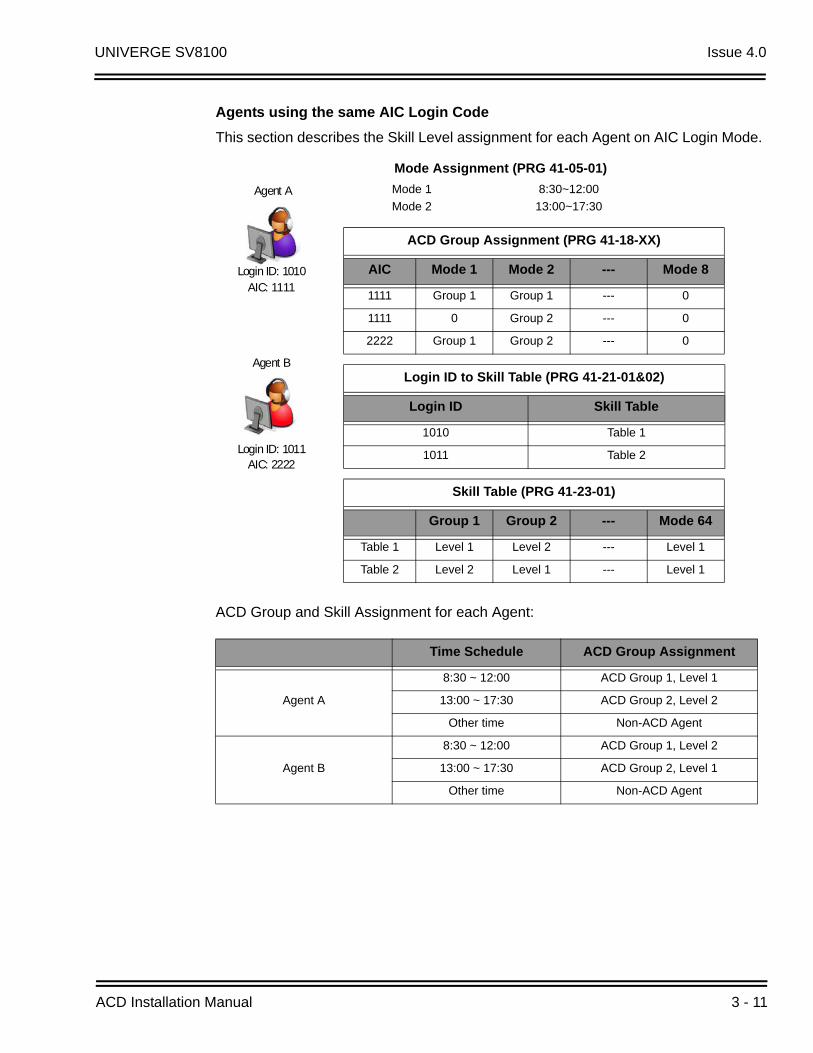
Agents using the same AIC Login Code
This section describes the Skill Level assignment for each Agent on AIC Login Mode.
ACD Group and Skill Assignment for each Agent:
Time Schedule ACD Group Assignment
Agent A
8:30 ~ 12:00 ACD Group 1, Level 1
13:00 ~ 17:30 ACD Group 2, Level 2
Other time Non-ACD Agent
Agent B
8:30 ~ 12:00 ACD Group 1, Level 2
13:00 ~ 17:30 ACD Group 2, Level 1
Other time Non-ACD Agent
Mode Assignment (PRG 41-05-01)
Mode 1 8:30~12:00
Mode 2 13:00~17:30
ACD Group Assignment (PRG 41-18-XX)
AIC Mode 1 Mode 2 --- Mode 8
1111 Group 1 Group 1 --- 0
1111 0 Group 2 --- 0
2222 Group 1 Group 2 --- 0
Login ID to Skill Table (PRG 41-21-01&02)
Login ID Skill Table
1010 Table 1
1011 Table 2
Skill Table (PRG 41-23-01)
Group 1 Group 2 --- Mode 64
Table 1 Level 1 Level 2 --- Level 1
Table 2 Level 2 Level 1 --- Level 1
Agent A
Login ID: 1010
Agent B
Login ID: 1011
AIC: 1111
AIC: 2222
ACD Installation Manual 3 - 11

Issue 4.0 UNIVERGE SV8100
Agents using more than one AIC Code
This section describes the Skill Level assignment for each Agent on AIC Login Mode.
ACD Group and Skill Assignment for each Agent:
Time Schedule ACD Group Assignment
Agent A
8:30 ~ 12:00 ACD Group 1, Level 1ACD Group 2, Level 2
13:00 ~ 17:30 ACD Group 1, Level 1
Other time Non-ACD Agent
Agent B
8:30 ~ 12:00 ACD Group 1, Level 2ACD Group 2, Level 1
13:00 ~ 17:30 ACD Group 2, Level 1
Other time Non-ACD Agent
Mode Assignment (PRG 41-05-01)
Mode 1 8:30~12:00
Mode 2 13:00~17:30
ACD Code Group Assignment
AIC Mode 1 Mode 2 --- Mode 8
1111 Group 1 Group 1 --- 0
2222 Group 1 Group 2 --- 0
3333 Group 2 0 --- 0
Login ID to Skill Table (PRG 41-21-01&02)
Login ID Skill Table
1010 Table 1
1011 Table 2
Skill Table (PRG 41-23-01)
Group 1 Group 2 --- Mode 64
Table 1 Level 1 Level 2 --- Level 1
Table 2 Level 2 Level 1 --- Level 1
Agent A
Login ID: 1010
Agent B
Login ID: 1011
AIC: 1111 AIC: 3333
AIC: 2222 AIC: 3333
3 - 12

UNIVERGE SV8100 Issue 4.0
Conditions
This feature requires Login ID (PRG41-01-02), and the skill level is set by each Login ID.
The agents cannot input the same Login ID at the same time.
The Skill Level has 7 levels, and priority level 1 is highest priority.
Each ACD Group can be assigned a different priority for each Login ID.
When the system receives ACD group call, the system distributes the call in order of the agent’s skill level.
When multiple agents have the same skill level, the call will then be delivered based on the longest idle.
This feature supports both Normal Login Mode and AIC Login Mode.
In case Login ID is not assigned to the system data or skill table is not assigned to the Login ID, then the system assigned to the agent as a highest level (level 1).
When a Call overflows to another ACD Group, the call will follow the skill level of the new ACD Group.
This feature requires the Version 5000 license (0034), and ACD Skill Based routing license (2105).
If Agents are logged in when Programming ACD Skill Based Routing, or adding the licenses, the Agents have to logout and back in to allow for the changes
Programming
11-17-01 ACD Group Pilot Numbers
This program assigns the ACD Master Number for each ACD Group.
15-07-01 Programmable Function Keys
Use Programmable Function Keys to assign functions to a multiline terminal line keys. For certain functions, you can append data to the key basic function. For example, the function 26 appended by data 1 makes a Group Call Pickup key for Pickup Group 1. You can also program Function Keys using Service Codes. To clear any previously programmed key, press 000 to erase any displayed code.
ACD Installation Manual 3 - 13
Issue 4.0 UNIVERGE SV8100
41-03-01 Incoming Ring Group Assignment for ACD Group - ACD Group Number
For each Incoming Trunk Ring Group (1~100) set up in Program 22-05-01, designate into which ACD Group (1~64) the trunks should ring for each of the eight Work Periods.
41-03-02 Incoming Ring Group Assignment for ACD Group - Night Announcement Service
For each Incoming Trunk Ring Group (1~100) set up in Program 22-05-01, designate whether the Night Announcement Service should be enabled (1) or disabled (0).
41-03-03 Incoming Ring Group Assignment for ACD Group - Priority Data
For each Incoming Trunk Ring Group (1~100) set up in Program 22-05-01, assign an Incoming Trunk Ring Group as normal (0) or define the priority (1~9).
41-05-01 ACD Agent Work Schedules
Use Program 41-05 : ACD Agent Work Schedules to set up the Work Schedules for ACD Agents and Groups. For each ACD Work Schedule (1~4), designate the start and stop times for each of the eight Work Periods. After you set up the schedules in this program, assign them to days of the week in Program 41-07. (This is the same program used by the Trunk Work Schedules.)
41-06-01 Trunk Work Schedules
Use Program 41-06 : Trunk Work Schedules to set up the Work Schedules for trunks. For each Work Schedule (1~4), designate the start and stop times for each of the eight Work Periods. After you set up the schedules, assign them to days of the week in Program 41-07. (This is the same program used by the ACD Agent Work Schedules.)
41-07-01 ACD Weekly Schedule Setup
Use Program 41-07 : ACD Weekly Schedule Setup to assign the four Work Schedules (1~4) to days of the week. The assignments you make in this program apply to both the ACD Agent Work Schedules (Program 41-05) and the Trunk Work Schedules (Program 41-06).
41-08-01 ACD Overflow Options - Overflow Operation Mode
For each ACD Group (1~64), assign the overflow mode (0~9). Each ACD Group can have unique overflow options.
41-08-02 ACD Overflow Options - ACD Overflow Destination
For each ACD Group (1~64), assign the destination ACD group (1~64) or option (65=Overflow Table in Program 41-09, 66=Voice Mail Integration (In-skin voice mail), 67 = Speed Dial Area (41-08-05), 68 = Incoming Ring Group (41-08-06).
3 - 14
UNIVERGE SV8100 Issue 4.0
41-08-03 ACD Overflow Options - Delay Announcement Source TypeFor each ACD Group (1~64), assign the announcement message types. Delay announcement functions are not available for ACD pilot number call. Each ACD Group can have unique overflow options.
41-08-04 ACD Overflow Options - ACD Overflow Transfer TimeFor each ACD Group (1~64), assign the overflow transfer time (0~64800 seconds).
41-08-05 ACD Overflow Options - System Speed Dial BinFor each ACD Group (1~64), enter the speed dial area (0~1999) to overflow to when 41-08-05 is set to 67.
41-08-06 ACD Overflow Options - Incoming Ring Group when Overflow
For each ACD Group (1~64), enter the Incoming Ring Group to overflow to when 41-08-02 is set to 68.
41-09-01 ACD Overflow Options - ACD Overflow Table Setting
Use Program 41-09 : ACD Overflow Table Setting to define the ACD group to which a call is transferred when overflow occurs.
41-17-01 ACD Login Mode Setup
Use Program 41-17 : ACD Login Mode Setup to define the ACD login mode for each extension. If the AIC Login Mode is enabled, set the AIC Login and AIC Logout service codes for the AIC members in Program 11-13-08 and 11-13-09.
41-18-01 ACD Agent Identity Code Setup – ACD Agent Identity Code
For each AIC Table (1~512), define the ACD Agent Identity Code (four digits).
41-18-02 ACD Agent Identity Code Setup – Default ACD Group Number
For each AIC Table (1~512), define the default ACD group number that is displayed with Queue Status (0=no setting, 1~64).
41-18-03 ACD Agent Identity Code Setup – ACD Group Number in Mode 1
For each AIC Table (1~512), define the ACD group number (0=No Setting, 1~64) in mode 1 work period.
41-18-04 ACD Agent Identity Code Setup – ACD Group Number in Mode 2
For each AIC Table (1~512), define the ACD group number (0=No Setting, 1~64) in mode 2 work period.
41-18-05 ACD Agent Identity Code Setup – ACD Group Number in Mode 3
For each AIC Table (1~512), define the ACD group number (0=no setting, 1~64) in mode 3 work period.
ACD Installation Manual 3 - 15

Issue 4.0 UNIVERGE SV8100
41-18-06 ACD Agent Identity Code Setup – ACD Group Number in Mode 4
For each AIC Table (1~512), define the ACD group number (0=no setting, 1~64) in mode 4 work period.
41-18-07 ACD Agent Identity Code Setup – ACD Group Number in Mode 5
For each AIC Table (1~512), define the ACD group number (0=no setting, 1~64) in mode 5 work period.
41-18-08 ACD Agent Identity Code Setup – ACD Group Number in Mode 6
For each AIC Table (1~512), define the ACD group number (0=No Setting, 1~64) in mode 6 work period.
41-18-09 ACD Agent Identity Code Setup – ACD Group Number in Mode 7
For each AIC Table (1~512), define the ACD group number (0=No Setting, 1~64) in mode 7 work period.
41-18-10 ACD Agent Identity Code Setup – ACD Group Number in Mode 8
For each AIC Table (1~512), define the ACD group number (0=No Setting, 1~64) in mode 8 work period.
41-21-01 ACD Login Setup - Login ID Code (Version 5000 or higher)
Input the Login ID(s) to be used.
41-21-02 ACD Login Setup - Skill Table Number (Version 5000 or higher)
Input the Skill Table number to be used for each Login ID.
41-22-01 Skill Base Routing (Version 5000 or higher)
This option determines if the Skill Based Routing is Used (1), or Not Used (0).
41-23-01 Skill Level (Version 5000 or higher)
Input the Skill Level for each Queue for each Skill Table number.
Related Features
None
Operation
None
3 - 16
UNIVERGE SV8100 Issue 4.0
THIS PAGE INTENTIONALLY LEFT BLANK
ACD Installation Manual 3 - 17

Issue 4.0 UNIVERGE SV8100
ACD Caller ID Based Routing
Description
The SV8100 can allocate an ACD incoming call to an agent by using Caller ID registered in a buffer. This is done by an ACD Agent pressing the [ACD Caller ID Marking Setup] Function Key. By the ACD Agent pressing the Function Key that marks the Caller ID to the system, and then the next time the same Caller ID calls back into ACD, the Caller ID based routing tries to route the call to the agent that marked the call. It provides smoother call center operation. ACD Caller ID based Routing requires both the Version 8000 license (0037) and the ACD Advance License (2105).
Conditions
By ACD Agent press the “Marking” LK while talking, routing information (Caller ID and ACD Agent) is registered in the CID buffer.
After CID registration is completed to the buffer, “Save Completed” is displayed in LCD, then “Marked” indication is displayed.
When more than one ACD Agents answer and mark the same CID, the information of last ACD Agent who pressed LK is registered.
When one ACD call is transferred and more than one ACD Agents have pressed LK, the information of the ACD Agent who has pressed LK lastly is registered
Even if the call transferred to ACD Agent which is in different groups, the information of the ACD Agent who has pressed LK lastly is registered to buffer.
When agent presses LK to mark a CID which has been marked by someone else, the LCD indicates “Marking Overwrite” to notify the CID is overwritten, and then indicates “Marked”.
Even though the CID information is registered by pressing the LK once, it is possible to cancel registration to press LK again during an ACD call.
When canceling CID information on buffer, the LCD will be back to ACD normal display after indicating “Canceled”.
When pressing LK with non-CID marking situation (see below), the LCD indicates “Marking Unavailable”, and then back to ACD normal display.
PRG41-24-01=Disable
Non-CID inbound call
3 - 18
UNIVERGE SV8100 Issue 4.0
Group Supervisor is able to register Caller ID regardless of the setting PRG41-04-01.
System Supervisor is not able to register the Caller ID information.
CID marking by pressing LK is possible while Group supervisor monitor/barge-in to ACD agent.
When multiple callers who has same Caller ID (e.g. same billing number) calls to ACD group, the system cannot distinguish that these calls.
When receiving ACD inbound call which is marked by last talked agent, LCD indicates “Marked” to show the call is marked on last talking.
If the agent which is the destination of CID base routing is not available because of busy status (see below for more status), the destination of call distribution is decided by current ACD rules.
Busy
Log out
Wrap up
Off-Duty
When receiving ACD inbound call which is marked by other agent, LCD indicates “Rerouted” to show the call is routed as marked call by someone else.
Caller ID base routing feature becomes the highest priority than other ACD related features. Call ID Base Routing >Skill Base Routing > Normal ACD
Both Call ID Base Routing and Skill Base Routing can be function at the same time.
If CID record exceeds the maximum buffer size of PRG41-24-04, the alarm report (#71) threshold for the CID buffer is shown as “Error”.
When total number of CID record is decrease and under the threshold (PRG41-24-04), alarm report (#71) is shown as “Recover”.
The CID record which is in buffer can be stored within the time specified by PRG41-24-03, and then it will be cleared automatically within 60 min if the time is over.
Registration information in a buffer includes ACD extension number or ACD Agent ID and Caller ID.
Caller ID buffer is shared by all the ACD Agent.
Information will be removed from the buffer when 2nd call comes to system and route to agent, regardless of whether ACD Agent answers the call.
ACD Installation Manual 3 - 19

Issue 4.0 UNIVERGE SV8100
If PRG41-24-02 is changed during system is running, all buffer records will be forced to delete.
CID buffer is not replicated to the NetLink system(s) so when the NetLink Failover occurs the CID data in the buffer will not be carried over.
When the system is rebooting, the CID data in the buffer will not be stored.
Since this feature needs a Function Key, Single Line Terminals are not supported.
Default Settings
Not enabled
System Availability
Terminals
DT300/Dterm ®85
DT700 excluding MH240
ML440
Programming
15-07-01 Programmable Function Keys
Define an ACD Caller ID Marking Setup (*34) key on the ACD agents that would like to Mark calls.
41-24-01 Caller ID marking setup
Enable/Disable the availability of setting that the ACD Agent can mark the originator caller ID, system base.
41-24-02 ACD Agent info for Caller ID
Set wither the Agent ID or extension number of the ACD Agent is used to mark with the CID in the buffer.
41-24-03 Caller ID Buffer Clear Timer
Set time interval for clearing stored caller ID record in buffer.
41-24-04 CID Buffer Store size
Set the CID Buffer Size. When the number of CID record is over the limit, CID buffer threshold alarm of PRG90-10-10(71) would be reported.
3 - 20

UNIVERGE SV8100 Issue 4.0
90-10-01 System Alarm Setup - Alarm Type
Assign a Major or Minor alarm status for Alarm 71 (Alarm for threshold of CID buffer). This program also assigns whether or not the alarm is displayed to a key telephone and whether or not the alarm information is reported to the predefined destination.
90-10-02 System Alarm Setup - Report
Assign whether or not the alarm is displayed to a multiline terminal and whether or not the alarm information is reported to the predefined destination in Program 90-11.
Related Features
ACD Skill Based Routing
Operation
When Caller ID is Marked during an ACD Call
When CID marking by pressing LK during an ACD call (ACD Agent Extension No)Assumption:
PRG41-24-02 ACD Agent info for Caller ID 0 : Agent Extension number
1. Receive ACD inbound call (Group1) from originator (214-555-1212), and answers the call by Agent100.
2. Agent100 is pressing Marking LK.=>LCD display [Save completed] -> [Marked]
=>CID registers buffer [CID=214-555-1212, ACD Agent Extension =100]
214-555-1212
ACD Installation Manual 3 - 21
Issue 4.0 UNIVERGE SV8100
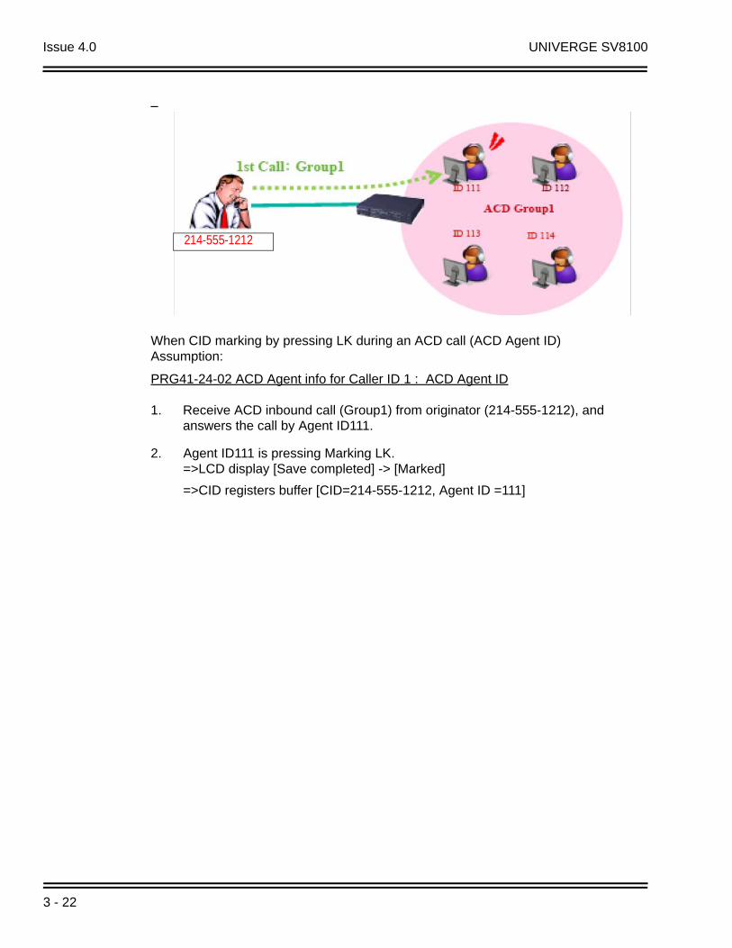
When CID marking by pressing LK during an ACD call (ACD Agent ID)Assumption:
PRG41-24-02 ACD Agent info for Caller ID 1 : ACD Agent ID
1. Receive ACD inbound call (Group1) from originator (214-555-1212), and answers the call by Agent ID111.
2. Agent ID111 is pressing Marking LK.=>LCD display [Save completed] -> [Marked]
=>CID registers buffer [CID=214-555-1212, Agent ID =111]
214-555-1212
3 - 22

UNIVERGE SV8100 Issue 4.0
When CID marking by pressing LK (It is transferred from another Agent in the same group)Assumption:
PRG41-24-02 ACD Agent info for Caller ID : Agent Extension number
1. Receive ACD inbound call (Group1) from originator (214-555-1212), and answers the call by Agent100.
2. Agent100 transfers ACD call to Agent102 in same ACD group.
3. Agent102 answers the transferred ACD call.
4. Agent 102 is pressing Marking LK.=> LCD display [Save completed] -> [Marked]=> CID registers buffer [CID=214-555-1212, Agent Extension number=102]
214-555-1212
ACD Installation Manual 3 - 23
Issue 4.0 UNIVERGE SV8100
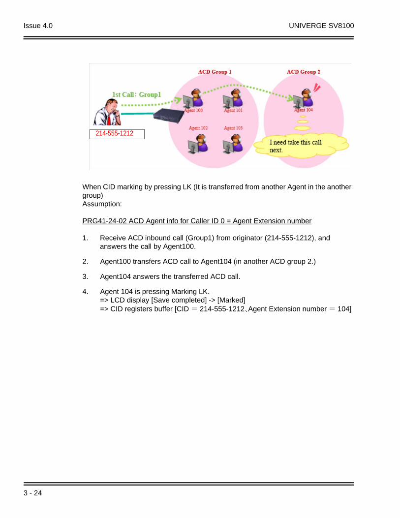
When CID marking by pressing LK (It is transferred from another Agent in the another group) Assumption:
PRG41-24-02 ACD Agent info for Caller ID 0 = Agent Extension number
1. Receive ACD inbound call (Group1) from originator (214-555-1212), and answers the call by Agent100.
2. Agent100 transfers ACD call to Agent104 (in another ACD group 2.)
3. Agent104 answers the transferred ACD call.
4. Agent 104 is pressing Marking LK. => LCD display [Save completed] -> [Marked] => CID registers buffer [CID = 214-555-1212、Agent Extension number = 104]
214-555-1212
3 - 24

UNIVERGE SV8100 Issue 4.0
When CID marking by pressing LK during an ACD call (By Group Supervisory) Assumption:
PRG41-24-02 ACD Agent info for Caller ID 0:Agent Extension number
1. Receive ACD inbound call (Group1) from originator (214-555-1212) or by transferring from someone, and answers the call by Group supervisor 105.
2. Group Supervisory 105 is pressing Marking LK. => LCD display [Save completed] -> [Marked] => CID registers buffer [CID = 214-555-1212, Agent Extension number = 105]
Group Supervisory can be registered Caller ID regardless of the setting PRG41-04-01.
System Supervisory cannot press LK to store CID information.
214-555-1212
ACD Installation Manual 3 - 25
Issue 4.0 UNIVERGE SV8100
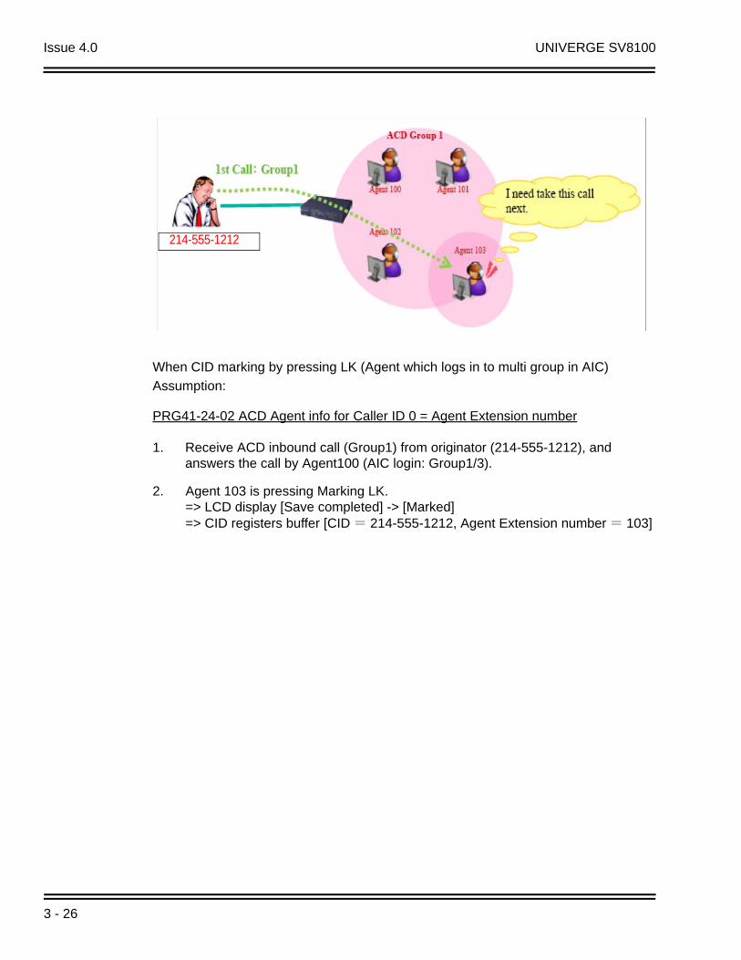
When CID marking by pressing LK (Agent which logs in to multi group in AIC)
Assumption:
PRG41-24-02 ACD Agent info for Caller ID 0 = Agent Extension number
1. Receive ACD inbound call (Group1) from originator (214-555-1212), and answers the call by Agent100 (AIC login: Group1/3).
2. Agent 103 is pressing Marking LK. => LCD display [Save completed] -> [Marked] => CID registers buffer [CID = 214-555-1212, Agent Extension number = 103]
214-555-1212
3 - 26

UNIVERGE SV8100 Issue 4.0
When CID marking by pressing LK (Marking unavailable)
Assumption:
PRG41-24-01 Caller ID marking setup:Disable
PRG41-24-02 ACD Agent info for Caller ID 0: Agent Extension number
1. Receive ACD inbound call (Group1) from originator (214-555-1212), and answers the call by Agent100.
2. Agent 100 is pressing Marking LK. => LCD display [Marking unavailable] -> Normal ACD call screen => Buffer is not retained.
214-555-1212
ACD Installation Manual 3 - 27

Issue 4.0 UNIVERGE SV8100
When it transfer by setting the [ACD Caller ID Marking Setup] Function Key Assumption:
PRG41-24-02 ACD Agent info for Caller ID 0: Agent Extension number
1. Receive ACD inbound call (Group1) from originator (214-555-1212), and answers the call by Agent100.
2. Agent 100 is pressing Marking LK. => LCD display [Save completed] -> [Marked] => CID registers buffer [CID = 214-555-1212、Agent Extension number = 100]
3. Agent100 transfers ACD call to Agent102.
4. Agent102 answers the transferred ACD call
5. Agent 102 is pressing Marking LK. => LCD display [Marking overwrite] -> [Marked] => CID registers buffer [CID = 214-555-1212、Agent Extension number = 102]
214-555-1212
3 - 28
UNIVERGE SV8100 Issue 4.0
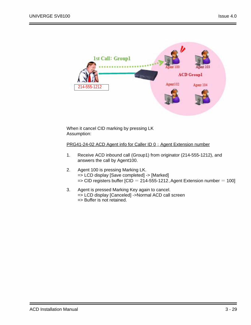
When it cancel CID marking by pressing LK Assumption:
PRG41-24-02 ACD Agent info for Caller ID 0:Agent Extension number
1. Receive ACD inbound call (Group1) from originator (214-555-1212), and answers the call by Agent100.
2. Agent 100 is pressing Marking LK. => LCD display [Save completed] -> [Marked] => CID registers buffer [CID = 214-555-1212、Agent Extension number = 100]
3. Agent is pressed Marking Key again to cancel. => LCD display [Canceled] ->Normal ACD call screen => Buffer is not retained.
214-555-1212
ACD Installation Manual 3 - 29
Issue 4.0 UNIVERGE SV8100
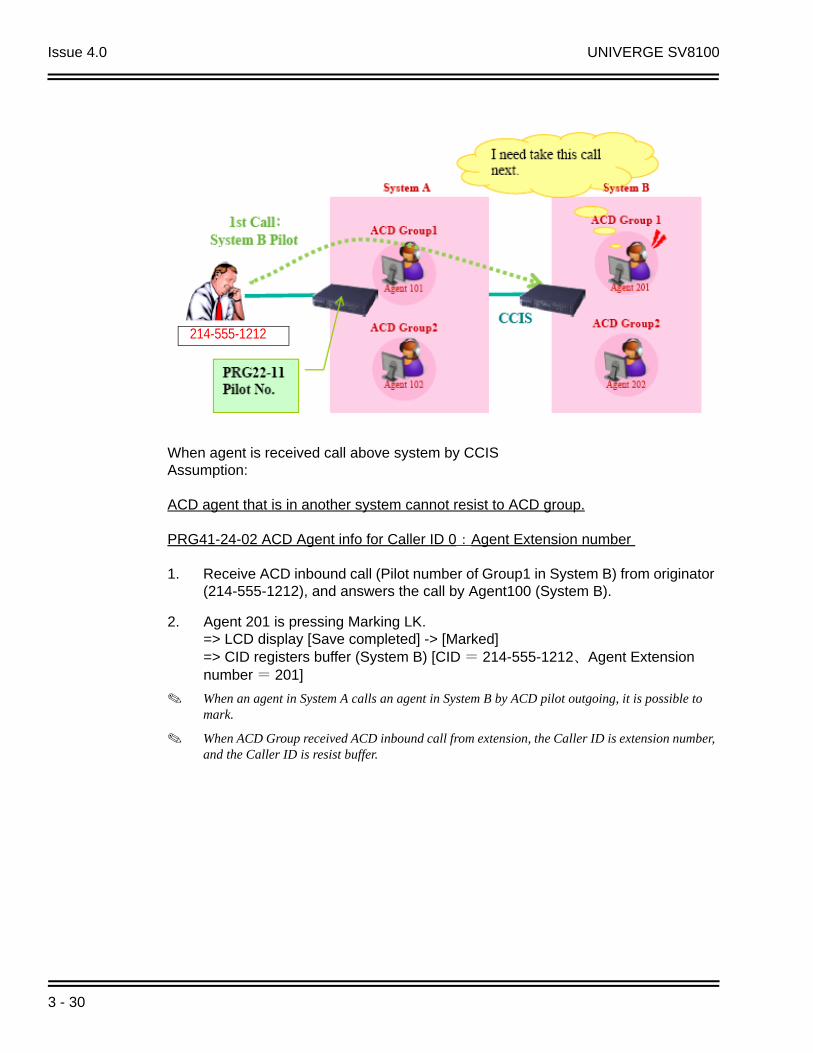
When agent is received call above system by CCIS Assumption:
ACD agent that is in another system cannot resist to ACD group.
PRG41-24-02 ACD Agent info for Caller ID 0:Agent Extension number
1. Receive ACD inbound call (Pilot number of Group1 in System B) from originator (214-555-1212), and answers the call by Agent100 (System B).
2. Agent 201 is pressing Marking LK. => LCD display [Save completed] -> [Marked] => CID registers buffer (System B) [CID = 214-555-1212、Agent Extension number = 201]
When an agent in System A calls an agent in System B by ACD pilot outgoing, it is possible to mark.
When ACD Group received ACD inbound call from extension, the Caller ID is extension number, and the Caller ID is resist buffer.
214-555-1212
3 - 30
UNIVERGE SV8100 Issue 4.0
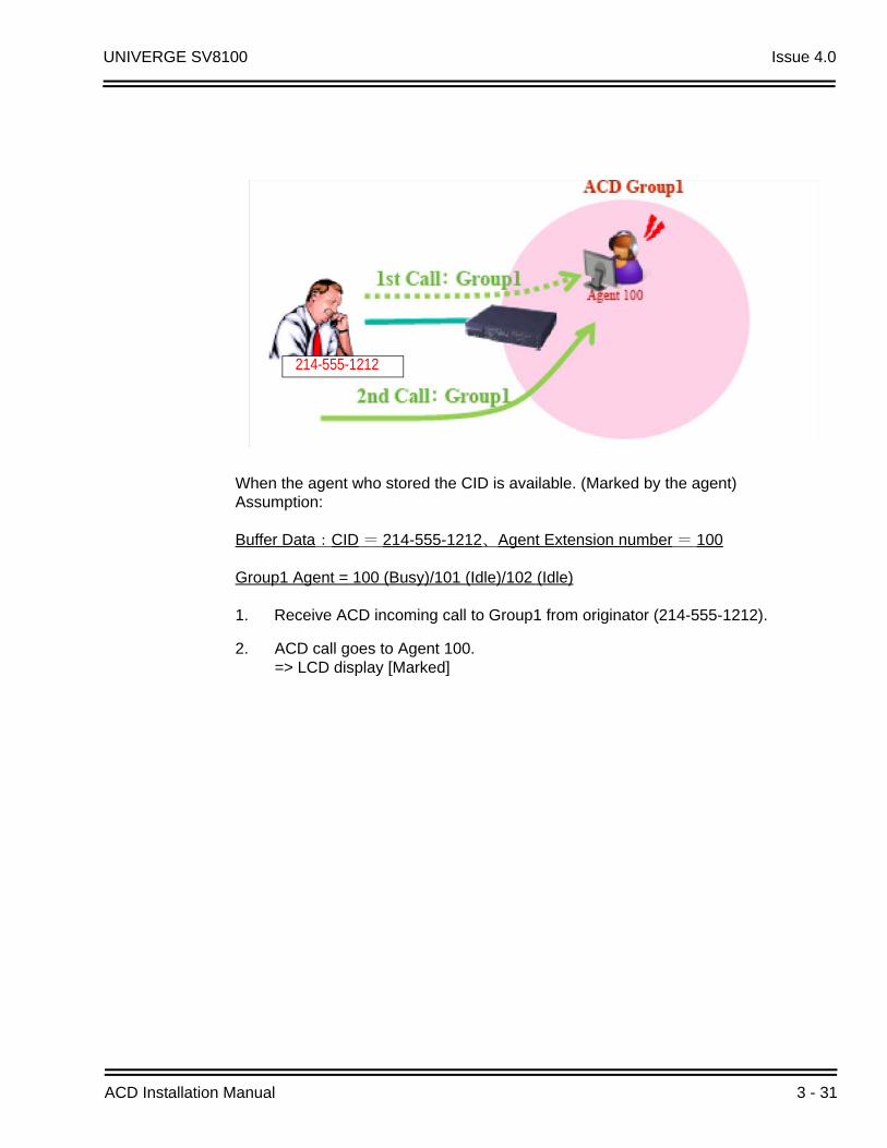
When the agent who stored the CID is available. (Marked by the agent) Assumption:
Buffer Data:CID = 214-555-1212、Agent Extension number = 100
Group1 Agent = 100 (Busy)/101 (Idle)/102 (Idle)
1. Receive ACD incoming call to Group1 from originator (214-555-1212).
2. ACD call goes to Agent 100. => LCD display [Marked]
214-555-1212
ACD Installation Manual 3 - 31

Issue 4.0 UNIVERGE SV8100
When the agent who stored the CID is not available. (Busy, Break mode, Wrap up, Logoff) Assumption:
Buffer Data : CID = 214-555-1212, Agent Extension number = 100
Group1 Agent=100 (Busy)/101 (Idle)/102 (Idle)
1. Incoming caller for Group1 (214-555-1212)
2. ACD call goes to Agent 100. => LCD display [Rerouted]
Since Agent100 is busy; the ACD call is not routed to the agent by CID base routing.
Agent101 is determined by the rules of normal ACD call.
214-555-1212
3 - 32

UNIVERGE SV8100 Issue 4.0
When ACD group which belongs to the destination Agent has changed (by changing system mode)
Assumption:
Buffer Data:CID = 214-555-1212、Agent Extension number = 100
Group1 Agent = 100 (Busy)/101 (Idle)/102 (Idle)
Group2 Agent = 105(Vacant)/106(Vacant)
1. Receive ACD incoming call from originator (214-555-1212) to Agent100. => LCD display [Marked]
Basically this ACD call goes to group2 instead of group1 because of system mode change. However, in this case the incoming call goes to Agent100 by CID base routing.
Similar case: the same originator calls to the different DID number (different ACD group)
214-555-1212
ACD Installation Manual 3 - 33

Issue 4.0 UNIVERGE SV8100
When agent is received call above system by CCIS Assumption:
ACD agent that is in another system cannot resist to ACD group.
Buffer Data (System B): CID = 214-555-1212、Agent Extension number = 201
System A Agent = 101 (Idle)/102 (Idle)
System B Agent = 201 (Idle)/202 (Idle)
1. Receive ACD inbound call (Pilot number of Group1 in System B) from originator (214-555-1212)
2. ACD call goes to Agent 201 => LCD display [Marked]
214-555-1212
3 - 34

UNIVERGE SV8100 Issue 4.0
Emergency Call
Description
If an ACD Agent needs assistance with a caller, they can place an Emergency Call to their ACD Group Supervisor. Once the supervisor answers the Emergency Call, they automatically monitor both the ACD Agent and the caller. If the agent needs assistance, the supervisor can press their Emergency Call key and join in the conversation. Emergency Call can be a big help to inexperienced ACD Agents that need technical advise or assistance with a difficult caller. The supervisor can easily listen to the conversation and then jump in if the situation gets out of hand.
If an ACD Supervisor is on an Emergency Call, you can allow calls to the ACD Supervisor to be transferred to the System Supervisor by setting Program 41-14-01 to '0.' The System Supervisor can be programmed to have an Emergency Call key and Supervisor Split key assigned.
Conditions
None
Default Setting
Emergency Call Overflow enabled (Program 41-14-01 = 0)
No Emergency Call keys assigned (Program 15-07-01: 12)
No Supervisor Split keys assigned (Program 15-07-01: 16)
Programming
15-07-01 Programmable Function Keys
Assign an Emergency Call key (code *12) to both the ACD Group Supervisor and the ACD Agent.
Assign a Supervisor Split key (code *16) to the ACD Group Supervisor.
ACD Installation Manual 3 - 35
Issue 4.0 UNIVERGE SV8100
41-14-01 ACD Options Setup – Emergency Call Operation Mode
Set the Emergency Call Operation Mode (0=Call system supervisory extension when group supervisory extension is busy, 1=No call to system supervisory extension when group supervisory extension is busy) for ACD Groups (01~64).
The supervisor must be logged in and have an Emergency Key programmed. By pressing the key once, the supervisor can monitor the call - pressing twice barges in on the call.
Related Features
Barge-In
Operation
To place an Emergency Call to your ACD Group Supervisor:
1. While talking to your caller, press Emergency Call Key (Program 15-07-01 or SC 752: *12).
Your Emergency Call key lights steadily. Your display shows: EMG CALL CALLING
The Emergency Call key on your ACD Group Supervisor's telephone flashes fast.
To answer an Emergency Call (from an agent in the ACD Group you supervise):
Your Emergency Call key flashes fast and your phone rings. Your display shows: EMG CALL CALL FROM.
1. Lift handset.
2. Press flashing Emergency Call Key (Program 15-07-01 or SC 752: *12).
You can hear both your ACD Agent and the outside caller, but you cannot talk to either party.
The display on both your phone and your agent's phone changes to: EMG CALL MONITOR.
To break into your ACD Agent's call (after answering their Emergency Call):
1. Press Emergency Call Key again.
The display on both your phone and your agent's phone changes to: EMG CALL BREAK IN.
You can converse with all three parties simultaneously.
The initial call will continue if you hang up.
3 - 36

UNIVERGE SV8100 Issue 4.0
To split away from your ACD Agent and talk to the outside caller (after breaking into the Emergency Call):
1. Press your Supervisor Split key (Program 15-07-01 or SC 752: *16).
The Supervisor Split key lights.
The display on both your phone and your agent's phone changes to EMG CALL WAIT.
The ACD Agent goes on Hold and you talk to the outside caller.
To end the Supervisor Split:
1. Press your Supervisor Split key (Program 15-07-01 or SC 752: *16).
You see: RELEASE ACD TEL? (1:YES, 0:NO)
2. Dial 0 to return to the Break In mode (where you were talking with the agent and the outside caller).
- OR -
3. Dial 1 to hang up on the ACD Agent and talk privately with the outside caller.
The ACD Agent hears busy tone until they hang up.
ACD Installation Manual 3 - 37

Issue 4.0 UNIVERGE SV8100
THIS PAGE INTENTIONALLY LEFT BLANK
3 - 38

UNIVERGE SV8100 Issue 4.0
Headset Operation (with AutomaticAnswer)
Description
An ACD Agent or ACD Group Supervisor can utilize a customer-provided headset in place of the handset. The headset conveniently frees up the user's hands for other work and provides privacy while on the call. In addition, an ACD Agent with a headset can have Automatic Answer. This allows an agent busy on a call to automatically connect to the next waiting call when they hang up.
Conditions
None
Default Setting
No headset keys defined (Program 15-07-01 = 05).
Automatic Answer disabled (Program 41-14-04 = 0).
Programming
15-07-01 Programmable Function Keys
Assign a function key for Headset operation (05).
20-13-06 Class of Service Options (Supplementary Service) – Automatic Off-Hook Signaling (Automatic Override)
Allows a busy extension ability to manually (0) or automatically (1) receive off-hook signals.
41-14-04 ACD Options Setup – Automatic Answer at Headset
For each ACD Group, enable (0) or disable (1) Automatic Answer for agents using headsets.
ACD Installation Manual 3 - 39

Issue 4.0 UNIVERGE SV8100
Related Features
Handsfree and Monitor
Handsfree Answerback/Forced Intercom Ringing
Operation
While in the headset mode, the hook switch is not functional.
To enable the headset:
1. Plug in the headset into the bottom of the phone.
2. Program a Headset Key (Program 15-07-01 or SC 751: 05).
To use the headset:
1. Press the Headset Key (Program 15-07-01 or SC 751: 05).
2. Press a line key to make a trunk call.
The Headset Key lights when you are in the headset mode.
If your ACD Group has Automatic Answer enabled and the mode is enabled on the multiline telephone, the next waiting call is automatically answered by the agent.
To Enable Automatic Answer for an Agent:
Press the Feature key and then press the Headset Key (Program 15-07-01 or SC 751: 05).
The Headset key flashes while Automatic Answer is active. Program 41-14-04 must also be set to allow Automatic Answer for the ACD group.
Incoming CO calls to the agent will automatically be answered. Ringing intercom calls are not automatically answered. Voice-announced intercom calls can be responded to handsfree.
To Disable Automatic Answer for an Agent:
Press the Feature Key and then press the Headset Key (Program 15-07-01 or SC 751: 05).
The Headset key goes out.
3 - 40

UNIVERGE SV8100 Issue 4.0
Hotline for ACD Agents
Description
Hotline gives a multiline terminal user One-button Calling and Transfer to another extension (the Hotline partner). Hotline helps co-workers that work closely together. The Hotline partners can call or transfer calls to each other just by pressing a single key.
Enhanced for ACD applications, Hotline provides a unique Busy Lamp Field (BLF) for ACD agents as well as a BLF for co-workers that are not ACD agents. The charts below show both sets of BLF indications.
Conditions
An extension user cannot use Hotline to pick up a call ringing their Hotline partner's extension.
The DSS Console will show agent status only if it is programmed as a ACD DSS Console in Program 30-01-01.
Hotline does not override Do Not Disturb.
BLF For ACD Agents
BLF Indicator ACD Agent Status
Off Idle and is not an ACD Agent
On Busy
Double Wink Off Making an emergency call
Wink Off Logged off or not installed
Double Wink On Logged on
BLF for co-workers who are not ACD Agents
BLF Indicator Co-worker Status
Off Idle
On Busy or ringing
Fast Flash In Do Not Disturb — All calls (option 3) or intercom calls (option 2)
ACD Installation Manual 3 - 41

Issue 4.0 UNIVERGE SV8100
Hotline always follows the Handsfree Answerback/Forced Intercom Ringing mode set at the called extension. The Hotline caller can override the setting, if desired.
If the partner's extension is busy, Hotline does not automatically activate Off Hook Signaling.
Default Setting
No Hotline keys programmed (no keys assigned code 01 in Program 15-07-01).
Programming
15-07-01 Programmable Function Keys
Assign a function key for Hotline (code 01 + partner's extension number).
20-13-06 Class of Service Options (Supplementary Service) – Automatic Off-Hook Signaling (Automatic Override)
Program 20-13-06 sets the conditions under which a Hotline key for a non-ACD Agent indicates that the covered extension is busy. This also applies to Reverse Voice Over and DSS Console keys for all co-workers.
With condition 1 in the following chart, the BLF LED is on only when both extension line appearances are busy. In conditions 2~4, the BLF LED is on when one line appearance is busy.
30-05-02
through
30-05-21 DSS Console Lamp Table
Customize the flash rates for the system DSS console.
Related Features
Direct Station Selection (DSS) Console
Do Not Disturb
Handsfree Answerback/Forced Intercom Ringing
Off-Hook Signaling
Programmable Function Keys
3 - 42
UNIVERGE SV8100 Issue 4.0
Operation
To place a call to your Hotline partner:
1. Press the Hotline key (Program 15-07-01 or SC 751: 01 + partner extension number).
You can optionally lift the handset after this step for privacy.
To transfer your outside call to your Hotline partner:
1. Press the Transfer key.
2. Press the Hotline key.
3. Announce call and hang up.
- OR -
Hang up to have the call wait at your Hotline partner unannounced. If unanswered, the call recalls like a regular transferred call.
To answer a call from your Hotline partner:
1. If you hear two beeps, speak toward the telephone.
- OR -
If your telephone rings, lift the handset.
ACD Installation Manual 3 - 43

Issue 4.0 UNIVERGE SV8100
THIS PAGE INTENTIONALLY LEFT BLANK
3 - 44

UNIVERGE SV8100 Issue 4.0
Identification Codes for ACDAgents
Description
Agent Identity Code (AIC)
An Agent Identity Code (AIC) allows ACD agents to log in any extension without setting Program 41-02-01 (ACD Log In). AIC also allows ACD agents to log in to multiple ACD groups at the same time. AIC and ACD groups for each work period can be set in Program 41-18-01 as shown in the following example.
With this example, ACD will work as follows:
Example 1: Log In with AIC 789
During Work Period 1, ACD agents will belong to ACD groups 1, 2, and 16 at the same time.
During Work Period 2, ACD agents will belong to only ACD group 1.
During Work Periods 3~8, ACD agents will not belong to any ACD group and the ACD extensions will work as normal extensions.
Example 2: Log In with AIC 567
During Work Periods 1~8, ACD agents will belong to only ACD group 10.
Example 3: Log In with AIC 678
During Work Periods 1~8, ACD agents will belong to ACD groups 2, 3 and 5 at the same time.
A supervisor cannot log in/out an AIC member as they are not normal ACD agents.
Table # AIC Operation
Group
Work Period
1 2 3 4 5 6 7 8
1 789 1 1 1 - - - - - -
2 789 1 2 1 - - - - - -
3 789 1 16 1 - - - - - -
4 567 10 10 10 10 10 10 10 10 10
5 678 2 2 2 2 2 2 2 2 2
6 678 2 3 3 3 3 3 3 3 3
7 678 2 5 5 5 5 5 5 5 5
ACD Installation Manual 3 - 45

Issue 4.0 UNIVERGE SV8100
Multiple Agent Log In
ACD agents can log in any extension with multiple AICs (up to three). Using the example setup above, ACD will work as follows:
Example 1: Log In with AIC 789 and 567
During Work Period 1, ACD agents will belong to ACD groups 1, 2, 10 and 16 at the same time.
During Work Period 2, ACD agents will belong to ACD groups 1 and 10.
During Work Periods 3~8, ACD agents will belong to only ACD group 10.
Example 2: Log In with AIC 789, 567 and 678
During Work Period 1, ACD agents will belong to ACD groups 1, 2, 3, 5, 10 and 16 at the same time.
During Work Period 2, ACD agents will belong to ACD groups 1, 2, 3, 5 and 10.
During Work Periods 3~8, ACD agents will belong to only ACD groups 2, 3, 5 and 10.
Some conditions with Multiple Agent Log In:
ACD agents cannot log in to the system supervisor or group supervisor’s extension.
In order to log in with AIC, the extension should be set to AIC Log In mode in Program 41-17-01.
If the extension is set to AIC log in mode in Program 41-17-01, the system will ignore the setting of Program 41-02-01 for the extension.
ACD agents can log in multiple extensions (up to the maximum capacity of the extension) with one AIC. For example, even if ACD agent “A” logs in extension 151 with the same AIC 789, ACD agent “B” can also log in to extension 351 with the same AIC 789 at the same time.
Conditions
A LAN connection from the UNIVERGE SV8100 system to a PC which has the UNIVERGE SV8100 ACD MIS program installed. Refer to the UNIVERGE SV8100 ACD MIS Supervisor’s Manual, for further information.
If the system has ID codes enabled, an agent must enter their ID code each time they log into an ACD Group.
3 - 46

UNIVERGE SV8100 Issue 4.0
Default Setting
Identification codes disabled (Program 41-01-02 = 0).
Each ACD Agent is set to normal mode, not AIC (Program 41-17-01).
Programming
41-01-02 System Options for ACD – Login ID Code Digit
Enter the number of digits agents must enter for their ID code (0~20). Enter 0 to disable the Login Codes for ACD Agents. If enabled, an ACD Agent can enter any code of valid length.
41-01-03 System Options for ACD – ACD MIS Connection Ports
Assign to LAN if you are going to use the UNIVERGE SV8100 ACD MIS.
41-17-01 ACD Login Mode Setup
Define the ACD login mode (0=Normal Login, 1=AIC Login) for each extension. If set to 1, a supervisor can not log in/out an AIC member as they are not normal ACD agents.
41-18-01 ACD Agent Identity Code Setup – ACD Agent Identity Code
For each AIC Table (1~512), define the ACD Agent Identity Code (four digits).
41-18-02 ACD Agent Identity Code Setup – Default ACD Group Number
For each AIC Table (1~512), define the default ACD group number that is displayed with Queue Status (0=no setting, 1~64).
41-18-03 ACD Agent Identity Code Setup – ACD Group Number in Mode 1
For each AIC Table (1~512), define the ACD group number (0=No Setting, 1~64) in mode 1 work period.
41-18-04 ACD Agent Identity Code Setup – ACD Group Number in Mode 2
For each AIC Table (1~512), define the ACD group number (0=No Setting, 1~64) in mode 2 work period.
41-18-05 ACD Agent Identity Code Setup – ACD Group Number in Mode 3
For each AIC Table (1~512), define the ACD group number (0=no setting, 1~64) in mode 3 work period.
41-18-06 ACD Agent Identity Code Setup – ACD Group Number in Mode 4
For each AIC Table (1~512), define the ACD group number (0=no setting, 1~64) in mode 4 work period.
ACD Installation Manual 3 - 47

Issue 4.0 UNIVERGE SV8100
41-18-07 ACD Agent Identity Code Setup – ACD Group Number in Mode 5
For each AIC Table (1~512), define the ACD group number (0=no setting, 1~64) in mode 5 work period.
41-18-08 ACD Agent Identity Code Setup – ACD Group Number in Mode 6
For each AIC Table (1~512), define the ACD group number (0=No Setting, 1~64) in mode 6 work period.
41-18-09 ACD Agent Identity Code Setup – ACD Group Number in Mode 7
For each AIC Table (1~512), define the ACD group number (0=No Setting, 1~64) in mode 7 work period.
41-18-10 ACD Agent Identity Code Setup – ACD Group Number in Mode 8
For each AIC Table (1~512), define the ACD group number (0=No Setting, 1~64) in mode 8 work period.
Related Features
Setting Up ACD for the First Time, Basic Operation
Operation
To log your extension into the ACD Group (when ID codes enabled in Program 41-01-02):
Multiline
Your display shows: WAIT ACD LOGIN
1. Press the Speaker key.
2. Dial 5.
You hear confirmation tone.
- OR -
Press ACD Log On/Off key (Program 15-07-01 or SC 752: code *10).
3. Dial the ID code.
You hear a single beep. Your display will show the ACD Group to which you are logged in. Although you can enter a code of any valid length, ask your supervisor which ID code you should enter.
3 - 48

UNIVERGE SV8100 Issue 4.0
Single Line Telephone
1. Lift handset.
2. Dial 5.
3. Dial the ID code.
You hear confirmation tone. Although you can enter a code of any valid length, ask you supervisor which ID code you should enter.
AIC Agent Log In (when your system has AIC enabled in Program 41-17-01):
To log in:
Multiline
1. Press the ACD Log In/Log Out key (Program 15-07-01 or SC 751: *10).
- OR -
Press the Speaker key and dial the AIC Log In service code (Program 11-13-08).
2. Dial the log in code (up to 20 digits).
This step is not required if the ID code is disabled in Program 41-01-02.
3. Dial the Agent Identity Code (AIC) (up to four digits).
The ACD Log In/Log Out key lights.
To log out (for single or multiple agent logins):
Multiline
All AIC log ins become logged out.
1. Press the ACD Log In/Log Out key (Program 15-07-01 or SC 751: *10).
2. Dial 1 to accept.
- OR -
1. Press the Speaker key and dial the AIC Log Out service code (Program 11-13-09).
The ACD Log In/Log Out key goes out.
2. Single Line Telephone
All AIC log ins become logged out.
1. Lift the handset.
ACD Installation Manual 3 - 49

Issue 4.0 UNIVERGE SV8100
2. Dial the AIC Log Out service code (Program 11-13-09).
- OR -
1. To log out of an ACD group without using AIC: Lift the handset.
2. Dial the ACD Log Out service code 655 (Program 11-13-02).
Multiple Agent Log In:
To log in:
Multiline
1. Once logged in with first AIC, press the ACD Log In/Log Out key (Program 15-07-01 or SC 751: *10).
2. Dial 0 to cancel the log out option.
3. Dial the Agent Identity Code (AIC) (up to four digits).
The ACD Log In/Log Out key lights.
- OR -
1. Press the Speaker key and dial the AIC Log In service code (Program 11-13-08).
2. Dial the Agent Identity Code (AIC) (up to four digits).
The ACD Log In/Log Out key lights.
Single Line Telephone
Follow Steps 1~3 to log in with additional AICs (up to three) at any time.
1. Lift the handset and dial the AIC Log In service code (Program 11-13-08).
2. Dial the log in code (up to 20 digits).
This step is not required if the ID code is disabled in Program 41-01-02.
3. Dial the first Agent Identity Code (AIC) (up to four digits).
You will hear a confirmation tone.
Complete Steps 4 and 5 when immediately logging in with additional AICs.
4. For second agent log: Dial the second Agent Identity Code (AIC) (up to four digits).
You will hear a confirmation tone.
5. For third agent log: Dial the third Agent Identity Code (AIC) (up to four digits).
You will hear a confirmation tone.
3 - 50
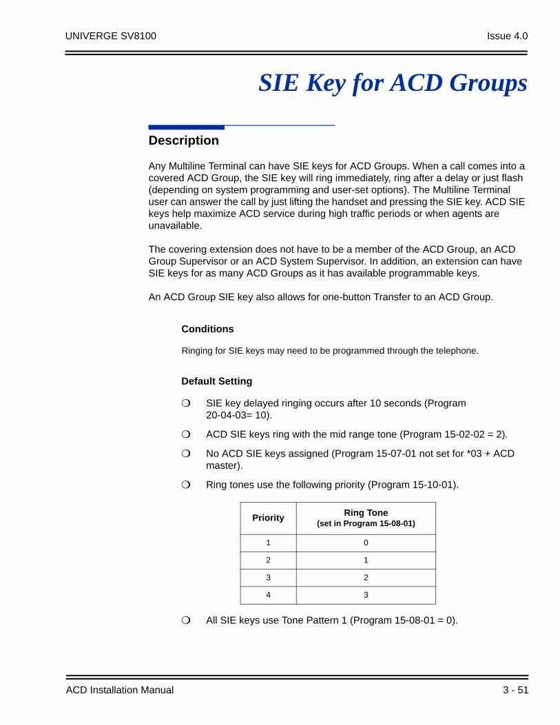
UNIVERGE SV8100 Issue 4.0
SIE Key for ACD Groups
Description
Any Multiline Terminal can have SIE keys for ACD Groups. When a call comes into a covered ACD Group, the SIE key will ring immediately, ring after a delay or just flash (depending on system programming and user-set options). The Multiline Terminal user can answer the call by just lifting the handset and pressing the SIE key. ACD SIE keys help maximize ACD service during high traffic periods or when agents are unavailable.
The covering extension does not have to be a member of the ACD Group, an ACD Group Supervisor or an ACD System Supervisor. In addition, an extension can have SIE keys for as many ACD Groups as it has available programmable keys.
An ACD Group SIE key also allows for one-button Transfer to an ACD Group.
Conditions
Ringing for SIE keys may need to be programmed through the telephone.
Default Setting
SIE key delayed ringing occurs after 10 seconds (Program 20-04-03= 10).
ACD SIE keys ring with the mid range tone (Program 15-02-02 = 2).
No ACD SIE keys assigned (Program 15-07-01 not set for *03 + ACD master).
Ring tones use the following priority (Program 15-10-01).
All SIE keys use Tone Pattern 1 (Program 15-08-01 = 0).
Priority Ring Tone(set in Program 15-08-01)
1 0
2 1
3 2
4 3
ACD Installation Manual 3 - 51

Issue 4.0 UNIVERGE SV8100
Programming
15-02-02 Multiline Telephone Basic Data Setup – Trunk Ring Tone
For the SIE key ring tone range assigned in Program 15-08-01 below, choose the extension’s desired ring tone (pitch) within the range selected. The choices are 1 (high), 2 (mid range), 3 (low), or 4~8 (Ring Tones 1~5). This also affects how certain trunk calls (such as DILs) ring the extension.
15-07-01 Programmable Function Keys
Assign function keys for ACD SIE (code *03 + ACD Group master number).
15-08-01 Incoming Virtual Extension Ring Tone Setup
Assign a ring tone range (0~4) to each extension. When a SIE key rings, it uses the range assigned in this option. The choices are 0 (tone pattern 1), 1 (tone pattern 2), 2 (tone pattern 3), 3 (tone pattern 4) and 4 (extension ring tone). The ring the user hears also depends on the setting of Program 15-02-02 above and Service Code 720.
15-09-01 Virtual Extension Ring Assignment
Individually program an extension's SIE keys to either ring (1) or not ring (0).
15-10-01 Incoming Virtual Extension Ring Tone Order Setup
Set the priority (1~4) for the ring tone ranges set in program 15-08-01 below. When more than one SIE key rings simultaneously, the tone with the highest priority (e.g., 1) rings. The other keys just flash.
15-11-01 Virtual Extension Delayed Ring Assignment
Individually program an extension’s SIE keys for Delayed Ringing (1) or Immediate Ringing (0). Also see Program 20-04-03 below.
20-04-03 System Options for Virtual Extensions – CAR/SIE/Virtual Extension Delay Interval
SIE keys set for delayed ringing (see Program 15-11-01 below) ring the covering extension after this interval.
22-03-01 Incoming Call Setup – Trunk Ring Tone Range
Select the ring tone range (0~8) for each trunk to ring in an ACD group. The trunk uses a ring tone within the range selected when it rings an extension There are four ring tones available.
Related Features
Programmable Function Keys
3 - 52

UNIVERGE SV8100 Issue 4.0
Operation
To answer a call ringing an ACD Group key:
1. Press flashing SIE key (Program 15-07-01 or SC 752: *03 + ACD master).
The SIE key may flash only, ring after a delay or ring immediately.
To Transfer a call to an ACD Group:
1. Place or answer call.
2. Press ACD Group SIE key.
3. Hang up to have call go through.
You cannot place a screened Transfer to an ACD Group.
To set up an ACD Group SIE key:
1. Press the Speaker key.
2. Dial 752.
3. Press the programmable key you want to program.
The previously programmed entry displays.
4. Dial 03.
5. Dial the ACD Group master number and press Hold.
You see the SET RING option.
6. Dial 1, 2, 3, 4, 5, 6, 7 and 8 to immediate ring for the Day, Night, Midnight, Rest, Day2, Night2, Midnight2, and Rest2 modes respectively.
- OR -
Press Hold and dial 1, 2, 3, 4, 5, 6, 7 and 8 to delay ring for the Day, Night, Midnight, Rest, Day2, Night2, Midnight2, and Rest2 modes respectively. You can make flexible entries. For example, you can have immediate ringing in the day
and night modes and delay ringing for the midnight and rest modes.
The ringing mode (delayed or immediate) follows system programming.
7. Press the Speaker key to hang up.
ACD Installation Manual 3 - 53

Issue 4.0 UNIVERGE SV8100
THIS PAGE INTENTIONALLY LEFT BLANK
3 - 54
UNIVERGE SV8100 Issue 4.0
Off-Duty Mode
Description
Off-Duty Mode temporarily logs-out an ACD agent's phone. There are two types of Off-Duty Mode:
Manual Off-Duty Mode
An ACD Agent can enable Manual Off-Duty Mode anytime they want to temporarily log out of the ACD Group. They might want to do this if they go to a meeting or get called away from their work area. While logged out, calls to the ACD Group will not ring the agent's phone.
Automatic Off-Duty Mode
When an ACD Group has Automatic Off-Duty Mode, the system will automatically put an agent's telephone in Off-Duty Mode if it is not answered. This ensures callers will not have to wait while ACD rings an extension that won't be answered. For multiline terminals, the system enables Automatic Off-Duty Mode for all phones with Off-Duty Mode keys. For single line telephones, you must set an option in programming to enable Automatic Off-Duty Mode.
Conditions
Automatic Off-Duty Mode does not time out. Once enabled, an agent must cancel Off-Duty Mode to return to service.
While active the agent will not receive any type of calls (in DND mode).
Default Setting
No Off-Duty Mode keys programmed (Program 15-07-01 = code *13).
Automatic Off-Duty Mode for single line telephone disabled (Program 41-14-07 = 0).
Programming
15-07-01 Programmable Function Keys
To enable Off-Duty Mode at a multiline telephone, assign a Off-Duty Mode key (code *13).
ACD Installation Manual 3 - 55

Issue 4.0 UNIVERGE SV8100
41-14-07 ACD Options Setup – Automatic Off-Duty for SLT
For each ACD Group (01~64), determine whether or not a single line telephone automatically changes to off-duty mode (0=No Change, 1=Change automatically).
41-14-08 ACD Options Setup – ACD Off Duty Mode
For each ACD Group (01~64), determine whether or not an agent can receive in internal call in off-duty mode (0=Can Not Receive, 1=Can Receive).
Related Features
Overflow Options
Wrap-Up Time
Operation
To activate Off-Duty Mode:
When you have a Off-Duty Mode key, the system automatically activates Off-Duty Mode if a call rings your phone and you do not pick it up.
Multiline
1. Press your Off-Duty Mode Key (Program 15-07-01 or SC 752: *13)
Your Off-Duty Mode Key lights.
Single Line Telephone
1. Lift the handset.
2. Dial 658.
When you activate Off-Duty Mode, your ACD Supervisor with a DSS Console sees your extension as logged out (i.e., wink off).
To cancel Off-Duty Mode:
Multiline
1. Press your Off-Duty Mode Key (Program 15-07-01 or SC 752: *13)
Your Off-Duty Mode Key goes out.
3 - 56
UNIVERGE SV8100 Issue 4.0
Single Line Telephone
1. Lift the handset.
2. Dial 659.
When you cancel Off-Duty Mode, your ACD Supervisor with a DSS Console sees your extension as available (logged in).
ACD Installation Manual 3 - 57

Issue 4.0 UNIVERGE SV8100
THIS PAGE INTENTIONALLY LEFT BLANK
3 - 58

UNIVERGE SV8100 Issue 4.0
One-Digit Dial Out
Description
When a caller to an ACD Group is being played a VRS Delay Announcement they can dial a one-digit option to dial out of the Group. The One-Digit Dial Out option can be pressed during the Announcement only, for “x” seconds after the Announcement only.
There is one one-digit option (0~9, & #) that can be set to transfer the call to an Extension in the system, VM with integration (Group #), Ring Group, Speed Dial Bin, and another ACD Group.
Conditions
The One-Digit Dial Out Option can not transfer out to a Department Group other then a VM Department Group.
Delay Announcement with In-Mail and ACI ports will not allow for the One-Digit Dial Out option.
Program 41-14-14 is used for both the 1st and 2nd Delay Announcements. You can not allow for one and not the other.
Programming
41-08-03 ACD Overflow Options – Delay Announcement Source Type
For each ACD Group (1~64), assign the announcement message types. Delay Announcement functions are not available for ACD pilot number call. Each ACD Group can have unique overflow options.
41-08-04 ACD Overflow Options – ACD Overflow Transfer Time
For each ACD Group (1~64), assign the overflow transfer time (0~64800 seconds).
41-11-01 VRS Delay Announcement – Delay Message Start Timer
For each ACD Group (01~64), determine how long the system waits (0~64800 seconds) before playing the delay message. This program is activated when the delay announcement source and options are assigned as VRS in Program 41-08-03.
ACD Installation Manual 3 - 59

Issue 4.0 UNIVERGE SV8100
41-11-02 VRS Delay Announcement – 1st Delay Message Number
For each ACD Group (01~64), assign the VRS message number to be used as the message source for the 1st Delay Announcement Message (0~101). This program is activated when the delay announcement source and options are assigned as VRS in Program 41-08-03.
41-11-03 VRS Delay Announcement – 1st Delay Message Sending Count
For each ACD Group (01~64), determine the 1st Delay Message Sending Count (0~255).
41-11-04 VRS Delay Announcement – 2nd Delay Message Number
For each ACD Group (01~64), assign the VRS message number to be used as the message source for the 2nd Delay Announcement Message (0~101). This program is activated when the delay announcement source and options are assigned as VRS in Program 41-08-03.
41-11-05 VRS Delay Announcement – 2nd Waiting Message Sending Count
For each ACD Group (01~64), determine the 2nd Delay Message Sending Count (0~255).
41-11-06 VRS Delay Announcement – Tone Kind at Message Interval
For each ACD Group (01~64), determine what the caller should hear between messages (0 = Ring Back Tone, 1 = MOH Tone, 2 = BGM) source.
41-11-07 VRS Delay Announcement – ACD Forced Disconnect Time After the 2nd Delay Message
For each ACD Group (01~64), when using ACD Overflow modes 3, 5, 8 and 9, enter how long after the caller hears the 2nd Announcement the system will disconnect (drop) the call. This prevents callers from waiting in queue an excessive amount of time. To disable this option (and allow callers to wait forever), enter 0.
41-11-08 VRS Delay Announcement – Queue Depth Announcement
For each ACD Group (01~64), use (0) to disable the Queue Depth Announcements, (1) after the 1st Delay Announcement only, (2) after the 2nd Delay Announcement only, or (3) after both the 1st and 2nd.
41-14-13-1 ACD Options Setup – ACD Queue 1 Digit Assignment
For each ACD Queue (1~64) assign the One-Digit number (0, 1~9, , #) to be used for the One-Digit Dial Out Option.
41-14-13-2 ACD Options Setup – Destination Number Type
For each ACD Queue (1~64), assign the Destination Number Type. (0 = None, 1 = Ext/VM, 2 = Ring Group, 3 = Speed Dial Bin, 4 = ACD Group).
41-14-13-3 ACD Options Setup – Destination Number
For each ACD Queue (1~64), assign the destination number for the assigned Destination Type. (Up to eight digits).
3 - 60

UNIVERGE SV8100 Issue 4.0
41-14-14 ACD Options Setup – DTMF Detection Assignment during Delay Announcement
For each ACD Queue (1~64), assign if the One-Digit Dial Out option(1 = Detects) or (0 = Does not detect) during the Delay Announcements.
41-14-15 ACD Options Setup – DTMF Detect Time after Delay Announcement Message
For each ACD Queue (1~64), assign the amount (0~64800 seconds) of time after the Delay Announcement that the One-Digit Dial Out option will work.
Related Features
None
Operation
None
ACD Installation Manual 3 - 61

Issue 4.0 UNIVERGE SV8100
THIS PAGE INTENTIONALLY LEFT BLANK
3 - 62

UNIVERGE SV8100 Issue 4.0
Overflow Options
Description
ACD offers extensive overflow options for each ACD Group. For example, a caller ringing in when all agents are unavailable can hear an initial announcement, called the 1st Announcement. This announcement can be a general greeting.
1st Announcement: Thank you for calling. All of our agents are currently busy helping other customers. Please stay on the line and we will help you shortly.
If the caller continues to wait, you can have them hear another announcement, called the 2nd Announcement.
2nd Announcement: Your business is important to us. Your call will be automatically answered by the first available agent. Please stay on the line.
If all the ACD Group's agents still are unavailable, the call can automatically overflow to another ACD Group, offsite via a speed dial bin, Ring Group, or the Voice Mail. If all agents in the overflow ACD Group are busy, Lookback Routing automatically ensures that the waiting call will ring into the first agent in either group that becomes free.
You can assign an ACD Group with any combination of 1st Announcement, 2nd Announcement and overflow method. You can have, for example, a Technical Service group that plays only the 2nd Announcement to callers and then immediately overflows to Voice Mail. At the same time, you can have a Customer Service group that plays both announcements and does not overflow.
The following overflow options are available:
No Overflow (Mode 0) A call waits in queue indefinitely for an available agent without an announcement. If no agents are logged in when the call rings the group, the caller hears ringback until they hang up or an agent logs in.
Overflow with No Announcement (Mode 1)If all agents are unavailable, a call to the ACD Group will overflow (i.e., reroute) to another ACD Group, offsite via a speed dial bin, Ring Group, or the Voice Mail after a programmed interval. The caller does not hear any messages as the call is rerouted.
ACD Installation Manual 3 - 63

Issue 4.0 UNIVERGE SV8100
No Overflow with 1st Announcement Only (Mode 2)A call waits in queue for an available agent, but the caller periodically hears the 1st Announcement message. This message can be a unique VRS message, a message from a PGD (2) port, message from an In-Mail, or the standard voice prompt, "Please hold on, all lines are busy. Your call will be answered when a line becomes free." In any case, the message repeats after a programmed interval.
When the PGD (2) is providing the 1st Announcement, it will continue to play until the call is answered or abandoned. This message will not start from the beginning because it is on a constant loop.
No Overflow with 1st and 2nd Announcements (Mode 3)When all agents are unavailable, the caller initially hears the 1st Announcement message. After a programmed interval, the caller hears the 2nd Announcement. The second announcement periodically repeats while the caller continues to wait. Each announcement can be a VRS message, a message from a PGD (2) port, message from an In-Mail, or the standard voice prompt, "Please hold on, all lines are busy. Your call will be answered when a line becomes free." Refer to Setting Up the 1st Announcement for Overflow Modes 2 and 4 on page 3-66.
When the PGD (2) is providing the 1st Announcement it will continue to play until the call is answered, abandoned or timer in 41-10-04 expires and Starts to play the 2nd Announcement. The 2nd Announcement will continue to play until the call is answered, abandoned or timer in 41-10-05 expires and drops the call The messages will not start from the beginning because it is on a constant loop.
Overflow with 1st Announcement Only (Mode 4)If all agents are unavailable, a call to the ACD Group will overflow (i.e., reroute) to another ACD Group, offsite via a speed dial bin, Ring Group, or the Voice Mail after a programmed interval. In addition, the caller periodically hears the 1st Announcement message. This message can be a VRS message, a message from a PGD (2) port, message from an In-Mail, or the standard voice prompt, "Please hold on, all lines are busy. Your call will be answered when a line becomes free." In either case, if the overflow destination is another ACD Group the message repeats after a programmed interval.
When the PGD (2) is providing the 1st Announcement it will continue to play until the call is answered or abandoned. This message will not start from the beginning because it is on a constant loop.
Overflow with 1st and 2nd Announcements (Mode 5)When all agents are unavailable, a call to the ACD Group will overflow (i.e., reroute) to another ACD Group, offsite via a speed dial bin, Ring Group, or the Voice Mail after a programmed interval. In addition, the caller initially hears the 1st Announcement message. After a programmed interval, the caller hears the 2nd Announcement. If the overflow destination is another ACD Group, the second announcement periodically repeats while the caller continues to wait. Each announcement can be a VRS message, a message from a PGD (2) port,
3 - 64
UNIVERGE SV8100 Issue 4.0
message from an In-Mail, or the standard voice prompt, "Please hold on, all lines are busy. Your call will be answered when a line becomes free."
When the PGD (2) is providing the 1st Announcement it will continue to play until the call is answered, abandoned or timer in 41-10-04 expires and Starts to play the 2nd Announcement. The 2nd Announcement will continue to play until the call is answered, abandoned or timer in 41-10-05 expires and drops the call The messages will not start from the beginning because it is on a constant loop.
No Overflow with 2nd Announcement Only (Mode 8)A call waits in queue for an available agent, but the caller periodically hears the 2nd Announcement message. This message can be a VRS message, a message from a PGD (2) port, message from an In-Mail, or the standard voice prompt, "Please hold on, all lines are busy. Your call will be answered when a line becomes free." In either case, the message repeats after a programmed interval.
When the PGD (2) is providing the 2nd Announcement it will continue to play until the call is answered, abandoned or timer in 41-10-05 expires and drops the call. This message will not start from the beginning because it is on a constant loop.
Overflow with 2nd Announcement Only (Mode 9)If all agents are unavailable, a call to the ACD Group will overflow (i.e., reroute) to another ACD Group, offsite via a speed dial bin, Ring Group, or the Voice Mail after a programmed interval. In addition, the caller periodically hears the 2nd Announcement message. This message can be a VRS message, a message from a PGD (2) port, message from an In-Mail, or the standard voice prompt, "Please hold on, all lines are busy. Your call will be answered when a line becomes free." In either case, if the overflow destination is another ACD Group the message repeats after a programmed interval.
When the PGD (2) is providing the 2nd Announcement it will continue to play until the call is answered, abandoned or timer in 41-10-05 expires and drops the call. This message will not start from the beginning because it is on a constant loop.
Music on Hold for Queued Callers
The system will optionally play ringback tone or Music on Hold to callers waiting in an ACD Group's queue. The source for the Music on Hold can be internally synthesized or an external customer-provided source. The external source connects to an ACI port. Refer to the Hardware Manual for more on connecting external music sources. Refer to the Features and Specifications Manual for details on setting up Music on Hold.
ACD Installation Manual 3 - 65
Issue 4.0 UNIVERGE SV8100
Multiple ACD Groups Programmed As Overflow Destination
The system can be programmed to transfer an overflow call to a specific ACD Group using Program 41-09-01. (In order to overflow to voice mail, offsite via a speed dial bin, Ring Group, use Program 41-08-02.) This option allows you to set the priority of each of the defined overflow destinations. Up to seven different ACD Groups can be programmed as overflow destinations for each group. The system, however, will not allow you to program an ACD Group with that same ACD Group as the overflow. (Example: ACD Group 1 cannot overflow to ACD Group 1.)
Temporary Override of the Overflow Destination
The system can be programmed to temporarily transfer overflow calls to a specific ACD Group using the ACD Overflow Control Programmable Function Key (Program 15-07-01, *18). When this key is active, the system will disregard PRG 41-08-XX for the Queue that they are a Supervisor of and follow PRG 41-08-XX for the destination and timer of the Queue assigned under the key. Only ACD Supervisors and ACD Group Supervisors can use this key. If both the Supervisor and Group Supervisor activate the temporary overflow for the same ACD Group, the System Supervisor’s programming will take priority and the system will overflow according to the System Supervisor’s setting. Multiple Overflow Control keys can be programmed on a Multiline Terminal, each with a different ACD Group as the overflow destination.
Setting Up the 1st Announcement for Overflow Modes 2 and 4
Mode 2 = No Overflow with 1st Announcement Only
Mode 4 = Overflow with 1st Announcement Only
For overflow modes 2 and 4, the system handles overflow timing and playing of the 1st Announcement Message to callers based on the interaction of the following ACD programming:
41-08-04 ACD Overflow Options – ACD Overflow Transfer Time
Overflow out of the ACD queue (mode 4 only) occurs after this timer expires. The system starts this timer as soon as a call goes into queue. Disable this timer (0) if you want queued callers to stay in queue until they are answered or they hang up. When it times out, the system overflows the caller to the destination defined in Program 41-09-01.
With a PGD(2) set as the announcement source:
41-10-01 ACI Delay Announcement – 1st Delay Announcement ACI Port Number
For each ACD group (01~64), set the 1st Delay Announcement ACI Port Number (0~96).
41-10-03 ACI Delay Announcement – 1st Delay Announcement Connection Timer
For each ACD group (01~64), determine how long the system waits before playing the Delay Message (0~64800 seconds).
3 - 66

UNIVERGE SV8100 Issue 4.0
With a VRS set as the announcement source:
22-01-11 System Options for Incoming Calls – VRS Waiting Message Interval Time
Set the timer for the interval between the Delayed Messages (0~64800 seconds).
41-11-01 VRS Delay Announcement – Delay Message Start Time
For each ACD group (01~64), set how long the system waits before playing the first delay announcement (0~64800 seconds).
41-11-02 VRS Delay Announcement – 1st Delay Message Number
For each ACD group (01~64), set the 1st Delay Message Number (01~101).
41-11-03 VRS Delay Announcement – 1st Delay Message Sending Count
For each ACD group (01~64), determine how many times the 1st Delay Message is played to the caller (0~255).
41-11-08 VRS Delay Announcement – Queue Depth Announcement
For each ACD Group (01~64), use (0) to disable the Queue Depth Announcements, (1) after the 1st Delay Announcement only, (2) after the 2nd Delay Announcement only, or (3) after both the 1st and 2nd.
With In-Mail set as the announcement source:
41-19-01 ACD Voice Mail Delay Announcement – Delay Message Start Time
For each ACD Group (01~64), set how long the system waits before playing the first Delay Announcement (0~64800 seconds).
41-19-02 ACD Voice Mail Delay Announcement – Mailbox Number for 1st Announcement Message
For each ACD Group (01~64), set the mailbox number to be used for the 1st Delay Announcement.
41-19-03 ACD Voice Mail Delay Announcement – 1st Delay Message Sending Count
For each ACD Group (01~64), determine how many times the 1st Delay Message is played to the caller (0~255).
41-19-08 ACD Voice Mail Delay Announcement – Delay Message Interval Time
For each ACD Group (01~64), set the timer for the interval between the Delayed Messages (0~64800 seconds).
ACD Installation Manual 3 - 67

Issue 4.0 UNIVERGE SV8100
Setting Up 1st and 2nd Announcements for Overflow Modes 3 and 5
Mode 3 = No Overflow with 1st and 2nd Announcements
Mode 5 = Overflow with 1st and 2nd Announcements
For overflow modes 3 and 5, the system plays the 1st and 2nd Announcements to callers and overflows based on the interaction of the following ACD programming:
41-08-04 ACD Overflow Options – ACD Overflow Transfer Time
Overflow out of the ACD queue (mode 5 only) occurs after this timer expires. It starts as soon as a call goes into queue. Disable this timer (0) if you want queued callers to stay in queue until they are answered or they hang up.
If Program 41-10-05, 41-11-07 or 41-19-07 is set, call will disconnect.
When it times out, the system overflows the caller to the destination defined in Program 41-09-01.
With a PGD(2) set as the announcement source:
41-10-01 ACI Delay Announcement – 1st Delay Announcement ACI Port Number
For each ACD group (01~64), set the 1st Delay Announcement ACI Port Number (0~96).
41-10-02 ACI Delay Announcement – 2nd Delay Announcement ACI Port Number
For each ACD group (01~64), set the 2nd Delay Announcement ACI Port Number (0~96).
2
3
4
After this times out, the 1st announcement plays again, if defined in programming.
After this times out, the 1st announcement plays for the first time. When a PGD(2) is used, it will continue to play the 1st Announcement Message until the call is
answered, or the caller hangs up, or overflow occurs.
When a call rings in, these timers start.
Overflow occurs (mode 4 only).
41-11-03 (VRS)
41-19-03 (In-Mail)
22-01-11 (VRS)
41-19-08 (In-Mail)
41-08-04
1
41-10-03 [PGD(2)]41-11-01 (VRS)
41-19-01 (In-Mail)
3 - 68

UNIVERGE SV8100 Issue 4.0
41-10-03 ACI Delay Announcement – 1st Delay Announcement Connection Timer
For each ACD group (01~64), determine how long the system waits before playing the Delay Message (0~64800 seconds).
41-10-04 ACI Delay Announcement – 2nd Delay Announcement Connection Timer
For each ACD group (01~64), set how long the system waits before playing the second delay announcement (0~64800 seconds).
41-10-05 ACI Delay Announcement – 2nd Delay Announcement Sending Duration
For each ACD group (01~64), determine how long the second announcement should play. After this timer expires, the call will disconnect unless the timer is set to “0” (0~64800 seconds).
With a VRS set as the announcement source (Program 41-08-03):
41-11-01 VRS Delay Announcement – Delay Message Start Timer
For each ACD group (01~64), determine how long the system waits before playing the Delay Message (0~64800 seconds).
41-11-02 VRS Delay Announcement – 1st Delay Message Number
For each ACD group (01~64), set the 1st Delay Message Number (01~101).
41-11-03 VRS Delay Announcement – 1st Delay Message Sending Count
For each ACD group (01~64), determine how many times the 1st Delay Message is played to the caller (0~255).
41-11-04 VRS Delay Announcement – 2nd Delay Message Number
For each ACD group (01~64), set the 2nd Delay Message Number (01~101).
41-11-05 VRS Delay Announcement – 2nd Waiting Message Sending Count
For each ACD group (01~64), determine how many times the 2nd Delay Message is played to the caller (0~255).
41-11-07 VRS Delay Announcement – ACD Forced Disconnect Time After the 2nd Message
For each ACD group (01~64), assign how long the system should wait after the end of the 2nd Announcement Message before disconnecting the call (0~64800).
41-11-08 VRS Delay Announcement – Queue Depth Announcement
For each ACD Group (01~64), use (0) to disable the Queue Depth Announcements, (1) after the 1st Delay Announcement only, (2) after the 2nd Delay Announcement only, or (3) after both the 1st and 2nd.
ACD Installation Manual 3 - 69
Issue 4.0 UNIVERGE SV8100
22-01-11 System Options for Incoming Calls – VRS Waiting Message Interval Time
Set the timer for the interval between the Delayed Messages (0~64800 seconds).
With a In-Mail set as the announcement source:
41-19-01 ACD Voice Mail Delay Announcement – Delay Message Start Time
For each ACD Group (01~64), set how long the system waits before playing the first Delay Announcement (0~64800 seconds).
41-19-02 ACD Voice Mail Delay Announcement – Mailbox Number for 1st Announcement Message
For each ACD Group (01~64), set the mailbox number to be used for the 1st Delay Announcement.
41-19-03 ACD Voice Mail Delay Announcement – 1st Delay Message Sending Count
For each ACD Group (01~64), determine how many times the 1st Delay Message is played to the caller (0~255).
41-19-04 ACD Voice Mail Delay Announcement – Mailbox Number for 2nd Announcement Message
For each ACD Group (01~64), set the mailbox number to be used for the 2nd Delay Announcement.
41-19-05 ACD Voice Mail Delay Announcement – 2nd Delay Message Sending Count
For each ACD Group (01~64), determine how many times the 2nd Delay Message is played to the caller (0~255).
41-19-07 ACD Voice Mail Delay Announcement – ACD Forced Disconnect Time After 2nd Announcement
For each ACD Group (01~64), assign how long the system should wait after the end of the 2nd Announcement Message before disconnecting the call (0~64800 seconds).
41-19-08 ACD Voice Mail Delay Announcement – Delay Message Interval Time
For each ACD Group (01~64), set the timer for the interval between the Delayed Messages (0~64800 seconds).
3 - 70
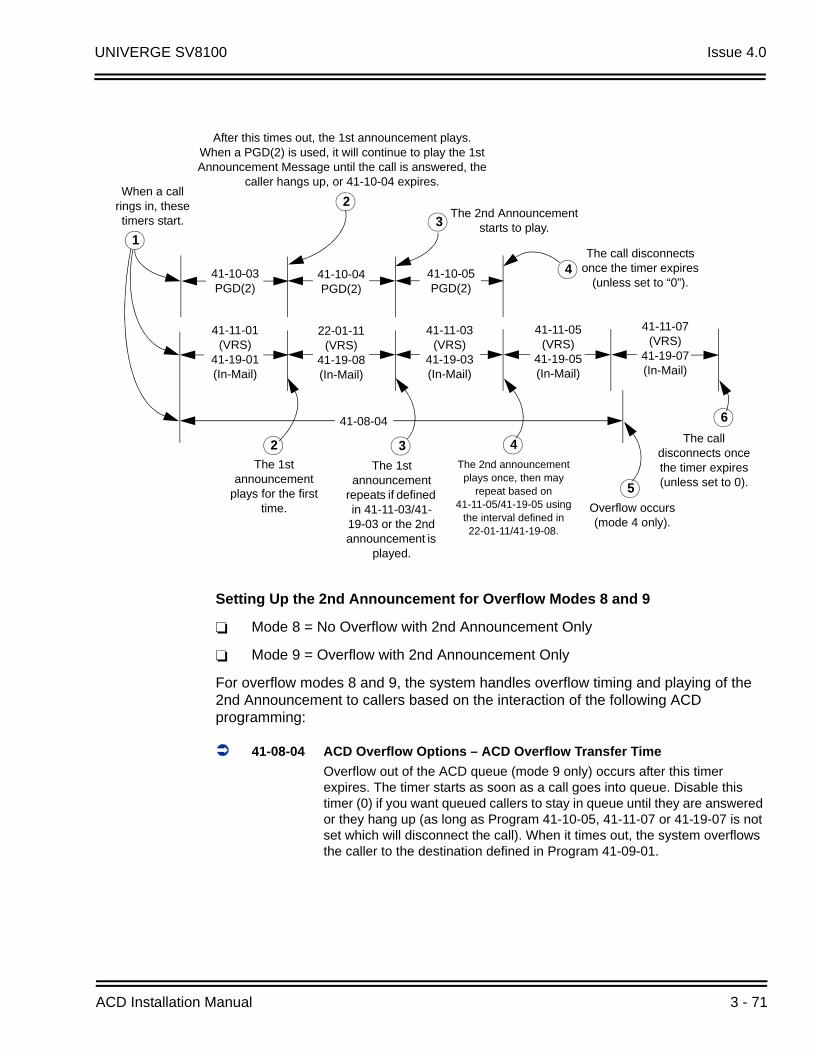
UNIVERGE SV8100 Issue 4.0
Setting Up the 2nd Announcement for Overflow Modes 8 and 9
Mode 8 = No Overflow with 2nd Announcement Only
Mode 9 = Overflow with 2nd Announcement Only
For overflow modes 8 and 9, the system handles overflow timing and playing of the 2nd Announcement to callers based on the interaction of the following ACD programming:
41-08-04 ACD Overflow Options – ACD Overflow Transfer Time
Overflow out of the ACD queue (mode 9 only) occurs after this timer expires. The timer starts as soon as a call goes into queue. Disable this timer (0) if you want queued callers to stay in queue until they are answered or they hang up (as long as Program 41-10-05, 41-11-07 or 41-19-07 is not set which will disconnect the call). When it times out, the system overflows the caller to the destination defined in Program 41-09-01.
2 3
6
The 1st announcement
repeats if defined in 41-11-03/41-
19-03 or the 2nd announcement is
played.
The 1st announcement
plays for the first time.
When a call rings in, these timers start.
Overflow occurs (mode 4 only).
41-11-05 (VRS)
41-19-05 (In-Mail)
22-01-11 (VRS)
41-19-08 (In-Mail)
41-08-04
41-11-07 (VRS)
41-19-07 (In-Mail)
41-11-03 (VRS)
41-19-03 (In-Mail)
41-11-01 (VRS)
41-19-01 (In-Mail)
4
5
The 2nd announcement plays once, then may
repeat based on 41-11-05/41-19-05 using
the interval defined in 22-01-11/41-19-08.
After this times out, the 1st announcement plays. When a PGD(2) is used, it will continue to play the 1st Announcement Message until the call is answered, the
caller hangs up, or 41-10-04 expires.
The call disconnects once the timer expires (unless set to 0).
41-10-04 PGD(2)
41-10-05 PGD(2)
41-10-03 PGD(2)
4
3
2
The call disconnects once the timer expires
(unless set to “0”).
The 2nd Announcement starts to play.
1
ACD Installation Manual 3 - 71
Issue 4.0 UNIVERGE SV8100
With a PGD(2) set as the announcement source:
41-10-02 ACI Delay Announcement – 2nd Delay Announcement ACI Port Number
For each ACD group (01~64), set the 2nd Delay Announcement ACI Port Number (0~96).
41-10-04 ACI Delay Announcement – 2nd Delay Announcement Connection Timer
For each ACD group (01~64), set how long the how long the system waits before playing the second delay announcement (0~64800 seconds).
41-10-05 ACI Delay Announcement – Delay Announcement Sending Duration
For each ACD group (01~64), determine how long the announcement should play. After this timer expires, the call will disconnect, unless the timer is set to 0 (0~64800 seconds).
With a VRS set as the announcement source:
22-01-11 System Options for Incoming Calls – VRS Waiting Message Interval Time
For each ACD group (01~64), set the timer for the interval between the Delayed Messages (0~64800 seconds).
41-11-01 VRS Delay Announcement – Delay Message Start Timer
For each ACD group (01~64), set how long the system waits before playing the first delay announcement (0~64800 seconds).
41-11-04 VRS Delay Announcement – 2nd Delay Message Number
For each ACD group (01~64), set the 2nd Delay Message Number (01~101).
41-11-05 VRS Delay Announcement – 2nd Waiting Message Sending Count
For each ACD group (01~64), determine how many times the 2nd Announcement Message will be played to a caller in queue for modes 8 and 9 (0~255).
41-11-07 VRS Delay Announcement – ACD Forced Disconnect Time After 2nd Message
For each ACD group (01~64), assign how long the system should wait after the end of the 2nd Announcement Message before disconnecting the call (0~64800).
41-11-08 VRS Delay Announcement – Queue Depth Announcement
For each ACD Group (01~64), use (0) to disable the Queue Depth Announcements, (1) after the 1st Delay Announcement only, (2) after the 2nd Delay Announcement only, or (3) after both the 1st and 2nd.
3 - 72
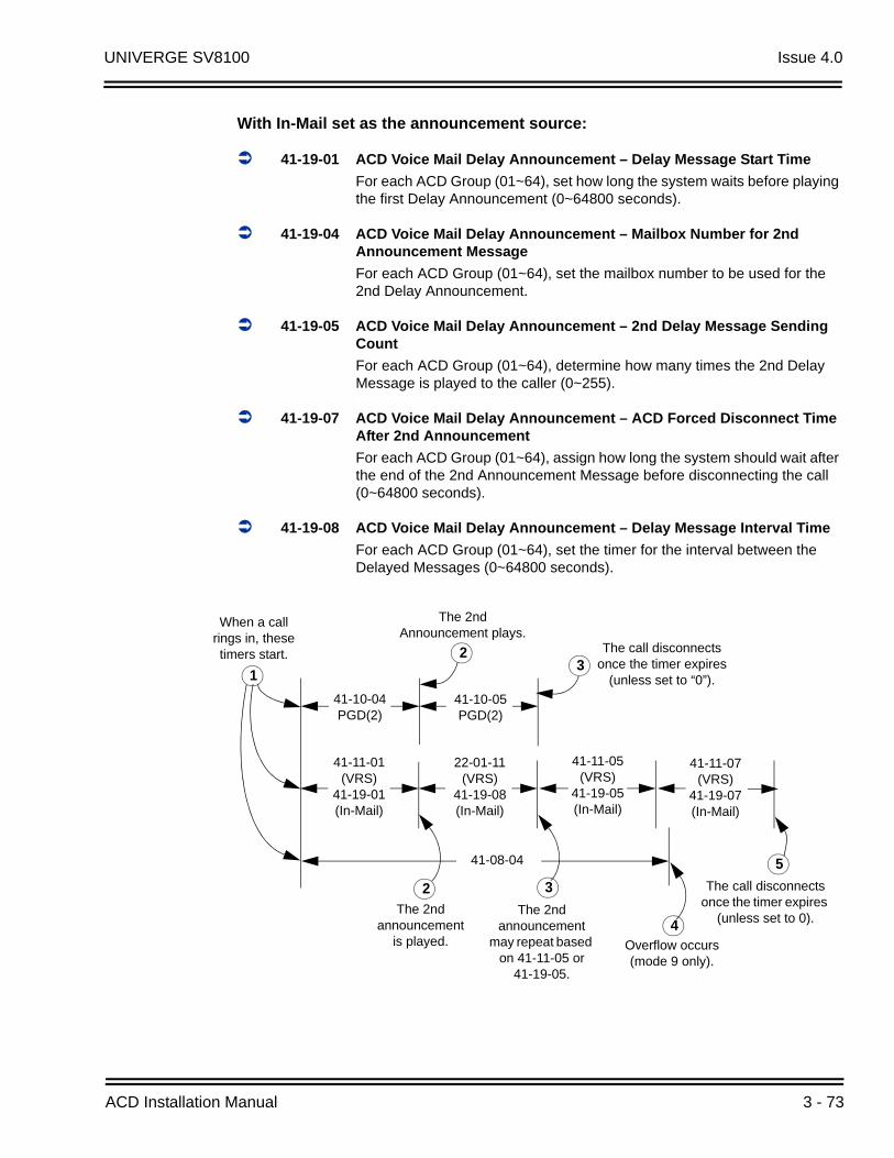
UNIVERGE SV8100 Issue 4.0
With In-Mail set as the announcement source:
41-19-01 ACD Voice Mail Delay Announcement – Delay Message Start Time
For each ACD Group (01~64), set how long the system waits before playing the first Delay Announcement (0~64800 seconds).
41-19-04 ACD Voice Mail Delay Announcement – Mailbox Number for 2nd Announcement Message
For each ACD Group (01~64), set the mailbox number to be used for the 2nd Delay Announcement.
41-19-05 ACD Voice Mail Delay Announcement – 2nd Delay Message Sending Count
For each ACD Group (01~64), determine how many times the 2nd Delay Message is played to the caller (0~255).
41-19-07 ACD Voice Mail Delay Announcement – ACD Forced Disconnect Time After 2nd Announcement
For each ACD Group (01~64), assign how long the system should wait after the end of the 2nd Announcement Message before disconnecting the call (0~64800 seconds).
41-19-08 ACD Voice Mail Delay Announcement – Delay Message Interval Time
For each ACD Group (01~64), set the timer for the interval between the Delayed Messages (0~64800 seconds).
2
5
The 2nd announcement
is played.
When a call rings in, these timers start.
Overflow occurs (mode 9 only).
41-11-05 (VRS)
41-19-05 (In-Mail)
22-01-11 (VRS)
41-19-08 (In-Mail)
41-08-04
1
41-11-01 (VRS)
41-19-01 (In-Mail)
3
4The 2nd
announcement may repeat based
on 41-11-05 or 41-19-05.
The call disconnects once the timer expires
(unless set to 0).
41-10-05 PGD(2)
41-10-04 PGD(2)
23
The call disconnects once the timer expires
(unless set to “0”).
The 2nd Announcement plays.
41-11-07 (VRS)
41-19-07 (In-Mail)
ACD Installation Manual 3 - 73
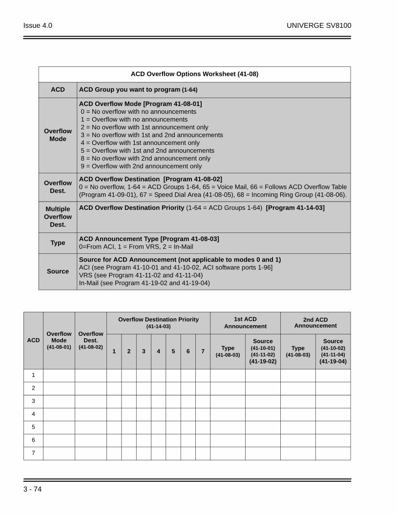
Issue 4.0 UNIVERGE SV8100
ACD Overflow Options Worksheet (41-08)
ACD ACD Group you want to program (1-64)
Overflow Mode
ACD Overflow Mode [Program 41-08-01] 0 = No overflow with no announcements 1 = Overflow with no announcements 2 = No overflow with 1st announcement only 3 = No overflow with 1st and 2nd announcements 4 = Overflow with 1st announcement only 5 = Overflow with 1st and 2nd announcements 8 = No overflow with 2nd announcement only 9 = Overflow with 2nd announcement only
Overflow Dest.
ACD Overflow Destination [Program 41-08-02]0 = No overflow, 1-64 = ACD Groups 1-64, 65 = Voice Mail, 66 = Follows ACD Overflow Table (Program 41-09-01), 67 = Speed Dial Area (41-08-05), 68 = Incoming Ring Group (41-08-06).
Multiple Overflow
Dest.
ACD Overflow Destination Priority (1-64 = ACD Groups 1-64) [Program 41-14-03]
TypeACD Announcement Type [Program 41-08-03]0=From ACI, 1 = From VRS, 2 = In-Mail
Source
Source for ACD Announcement (not applicable to modes 0 and 1)ACI (see Program 41-10-01 and 41-10-02, ACI software ports 1-96]VRS (see Program 41-11-02 and 41-11-04)In-Mail (see Program 41-19-02 and 41-19-04)
ACDOverflow
Mode(41-08-01)
OverflowDest.
(41-08-02)
Overflow Destination Priority(41-14-03)
1st ACD Announcement
2nd ACD Announcement
1 2 3 4 5 6 7 Type(41-08-03)
Source(41-10-01)(41-11-02)
(41-19-02)
Type(41-08-03)
Source(41-10-02)(41-11-04)
(41-19-04)
1
2
3
4
5
6
7
3 - 74
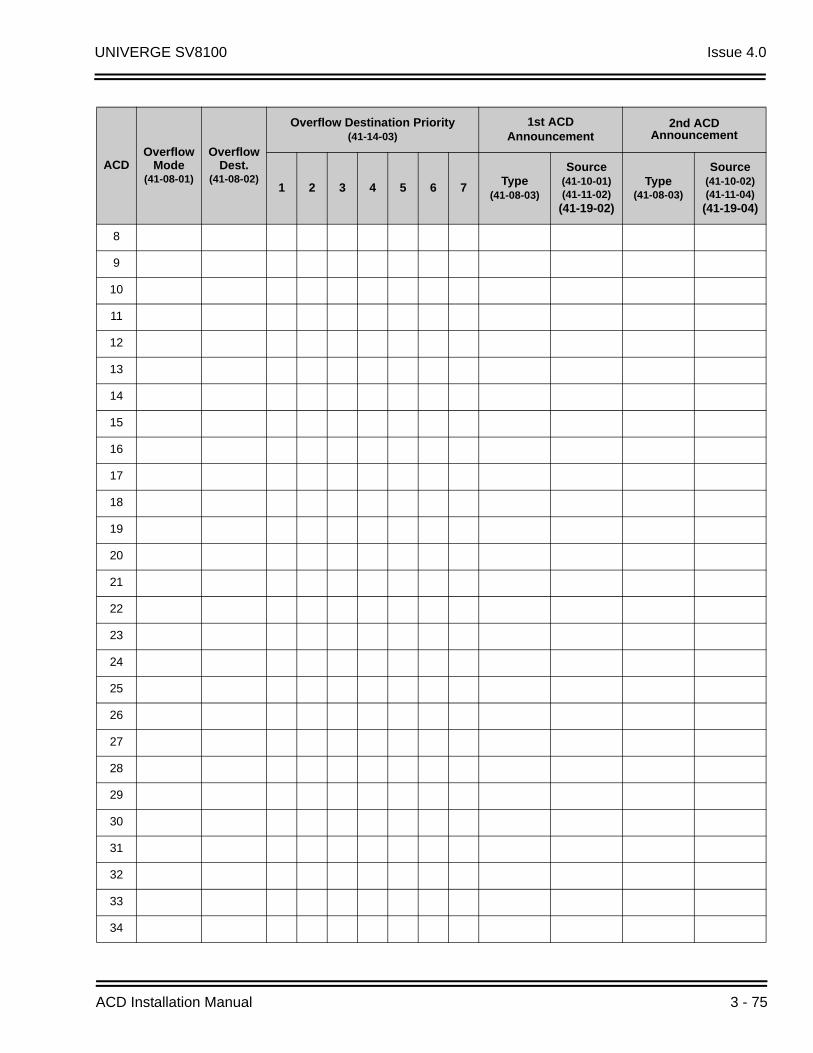
UNIVERGE SV8100 Issue 4.0
8
9
10
11
12
13
14
15
16
17
18
19
20
21
22
23
24
25
26
27
28
29
30
31
32
33
34
ACDOverflow
Mode(41-08-01)
OverflowDest.
(41-08-02)
Overflow Destination Priority(41-14-03)
1st ACD Announcement
2nd ACD Announcement
1 2 3 4 5 6 7Type
(41-08-03)
Source(41-10-01)(41-11-02)
(41-19-02)
Type(41-08-03)
Source(41-10-02)(41-11-04)
(41-19-04)
ACD Installation Manual 3 - 75
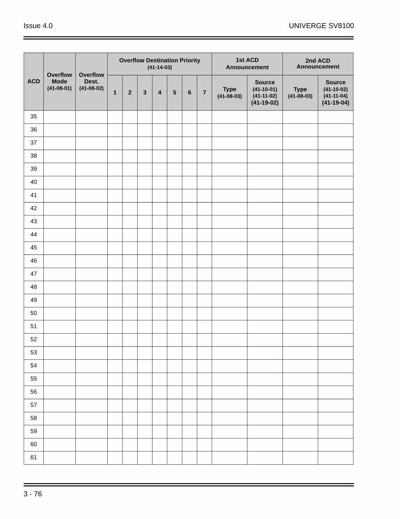
Issue 4.0 UNIVERGE SV8100
35
36
37
38
39
40
41
42
43
44
45
46
47
48
49
50
51
52
53
54
55
56
57
58
59
60
61
ACDOverflow
Mode(41-08-01)
OverflowDest.
(41-08-02)
Overflow Destination Priority(41-14-03)
1st ACD Announcement
2nd ACD Announcement
1 2 3 4 5 6 7 Type(41-08-03)
Source(41-10-01)(41-11-02)
(41-19-02)
Type(41-08-03)
Source(41-10-02)(41-11-04)
(41-19-04)
3 - 76
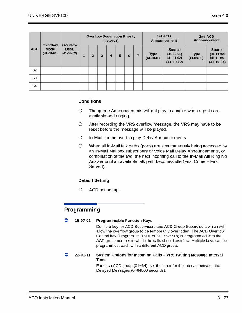
UNIVERGE SV8100 Issue 4.0
Conditions
The queue Announcements will not play to a caller when agents are available and ringing.
After recording the VRS overflow message, the VRS may have to be reset before the message will be played.
In-Mail can be used to play Delay Announcements.
When all In-Mail talk paths (ports) are simultaneously being accessed by an In-Mail Mailbox subscribers or Voice Mail Delay Announcements, or combination of the two, the next incoming call to the In-Mail will Ring No Answer until an available talk path becomes idle (First Come – First Served).
Default Setting
ACD not set up.
Programming
15-07-01 Programmable Function Keys
Define a key for ACD Supervisors and ACD Group Supervisors which will allow the overflow group to be temporarily overridden. The ACD Overflow Control key (Program 15-07-01 or SC 752: *18) is programmed with the ACD group number to which the calls should overflow. Multiple keys can be programmed, each with a different ACD group.
22-01-11 System Options for Incoming Calls – VRS Waiting Message Interval Time
For each ACD group (01~64), set the timer for the interval between the Delayed Messages (0~64800 seconds).
62
63
64
ACDOverflow
Mode(41-08-01)
OverflowDest.
(41-08-02)
Overflow Destination Priority(41-14-03)
1st ACD Announcement
2nd ACD Announcement
1 2 3 4 5 6 7Type
(41-08-03)
Source(41-10-01)(41-11-02)
(41-19-02)
Type(41-08-03)
Source(41-10-02)(41-11-04)
(41-19-04)
ACD Installation Manual 3 - 77
Issue 4.0 UNIVERGE SV8100
41-08-01 ACD Overflow Options – Overflow Operation Mode
For each ACD Group (1~64), assign the overflow mode (0~9). Each ACD Group can have unique overflow options.
41-08-02 ACD Overflow Options – ACD Overflow Destination
For each ACD Group (1~64), assign the destination ACD group (1~64) or option (65=Overflow Table in Program 41-09, 66=Voice Mail Integration (In-skin voice mail), 67 = Speed Dial Area (41-08-05), 68 = Incoming Ring Group (41-08-06).
41-08-03 ACD Overflow Options – Delay Announcement Source Type
For each ACD Group (1~64), assign the announcement message types. Delay announcement functions are not available for ACD pilot number call. Each ACD Group can have unique overflow options.
41-08-04 ACD Overflow Options – ACD Overflow Transfer Time
For each ACD Group (1~64), assign the overflow transfer time (0~64800 seconds).
41-08-05 ACD Overflow Options – System Speed Dial Bin
For each ACD Group (1~64), enter the speed dial area (0~1999) to overflow to when 41-08-05 is set to 67.
41-08-06 ACD Overflow Options – Incoming Ring Group when Overflow
For each ACD Group (1~64), enter the Incoming Ring Group to overflow to when 41-08-02 is set to 68.
41-09-01 ACD Overflow Table Setting
For each ACD Group (1~64), assign the overflow ACD Groups according to the priority in which the calls should ring the ACD Groups (for each ACD Group, up to seven destinations can be programmed). If, while the call is ringing, the extension to which the call was transferred becomes available, both the extension and the overflow ACD group will ring.
41-10-01 ACI Delay Announcement – 1st Delay Announcement ACI Port Number
For each ACD group (01~64), set the 1st Delay Announcement ACI Port Number (0~96).
41-10-02 ACI Delay Announcement – 2nd Delay Announcement ACI Port Number
For each ACD group (01~64), set the 2nd Delay Announcement ACI Port Number (0~96).
41-10-03 ACI Delay Announcement – 1st Delay Announcement Connection
For each ACD group (01~64), determine how long the system waits before playing the Delay Message (0~64800 seconds).
3 - 78
UNIVERGE SV8100 Issue 4.0
41-10-04 ACI Delay Announcement – 2nd Delay Announcement Connection Timer
For each ACD group (01~64), set the timer the system waits before playing the second.
41-10-05 ACI Delay Announcement – 2nd Delay Announcement Sending Duration
For each ACD group (01~64) using ACD Overflow modes 3, 5, 8 and 9, enter how long after the caller hears the 2nd Announcement the system will disconnect (drop) the call. To disable this option (and allow callers to wait forever), enter 0.
41-11-01 VRS Delay Announcement – Delay Message Start Timer
For each ACD Group (01~64), determine how long the system waits before playing the delay Message. This program is activated when the delay announcement source and options are assigned as VRS in Program 41-08-03.
41-11-02 VRS Delay Announcement – 1st Delay Message Number
For each ACD Group (01~64), assign the VRS message number to be used as the message source for the 1st Delay Announcement Message (0~101). This program is activated when the delay announcement source and options are assigned as VRS in Program 41-08-03.
41-11-03 VRS Delay Announcement – 1st Delay Message Sending Count
For each ACD Group (01~64), determine the 1st Delay Message Sending Count (0~255).
41-11-04 VRS Delay Announcement – 2nd Delay Message Number
For each ACD Group (01~64), assign the VRS message number to be used as the message source for the 2nd Delay Announcement Message (0~101). This program is activated when the delay announcement source and options are assigned as VRS in Program 41-08-03.
41-11-05 VRS Delay Announcement – 2nd Waiting Message Sending Count
For each ACD Group (01~64), determine the 2nd Delay Message Sending Count (0~255).
41-11-06 VRS Delay Announcement – Tone Kind at Message Interval
For each ACD Group (01~64), determine what the caller should hear between messages (0=Ring Back Tone, 1=MOH Tone, 2=BGM source).
41-11-07 VRS Delay Announcement – ACD Forced Disconnect Time After the 2nd Delay Message
For each ACD Group (01~64) when using ACD Overflow modes 3, 5, 8 and 9, enter how long after the caller hears the 2nd Announcement the system will disconnect (drop) the call. This prevents callers from waiting in queue an excessive amount of time. To disable this option (and allow callers to wait forever), enter 0.
ACD Installation Manual 3 - 79

Issue 4.0 UNIVERGE SV8100
41-11-08 VRS Delay Announcement – Queue Depth Announcement
For each ACD Group (01~64), use (0) to disable the Queue Depth Announcements, (1) after the 1st Delay Announcement only, (2) after the 2nd Delay Announcement only, or (3) after both the 1st and 2nd.
41-14-03 ACD Options Setup – ACD Priority for Overflow Calls
Set the priority for overflow calls (0=Own Group Priority, 1=Priority Set by Program 41-03-03) for ACD Groups (01~64).
41-14-06 ACD Options Setup – Call Queuing after 2nd Announcement
Use this option to determine whether the caller should hear the 2nd Delay Announcement and then be taken out of queue [(1=Disable), or placed back into queue (0=Enable)].
41-16-01 ACD Threshold Overflow – Number of Calls in Queue
For each ACD group (01~64), define the maximum number of calls in ACD queue (0=No Limit, 1~200) before the call overflows.
41-16-02 ACD Threshold Overflow – Operation Mode for ACD Queue
For each ACD group (01~64), determine how the system handles ACD calls when the maximum number of ACD calls in queue has been reached (0=Last Waiting Call is Transferred, 1=Longest Waiting Call is Transferred, 2=Send Busy Tone).
41-19-01 ACD Voice Mail Delay Announcement – Delay Message Start Time
For each ACD Group (01~64), set how long the system waits before playing the first Delay Announcement (0~64800 seconds).
41-19-02 ACD Voice Mail Delay Announcement – Mailbox Number for 1st Announcement Message
For each ACD Group (01~64), set the mailbox number to be used for the 1st Delay Announcement.
41-19-03 ACD Voice Mail Delay Announcement – 1st Delay Message Sending Count
For each ACD Group (01~64), determine how many times the 1st Delay Message is played to the caller (0~255).
41-19-04 ACD Voice Mail Delay Announcement – Mailbox Number for 2nd Announcement Message
For each ACD Group (01~64), set the mailbox number to be used for the 2nd Delay Announcement.
41-19-05 ACD Voice Mail Delay Announcement – 2nd Delay Message Sending Count
For each ACD Group (01~64), determine how many times the 2nd Delay Message is played to the caller (0~255).
3 - 80
UNIVERGE SV8100 Issue 4.0
41-19-06 ACD Voice Mail Delay Announcement – Wait Tone Type at Message Interval
For each ACD Group (01~64), determine what the caller should hear between messages (0 = Ring Back Tone, 1 = MOH Tone, 2 = BGM source).
41-19-07 ACD Voice Mail Delay Announcement – ACD Forced Disconnect Time After 2nd Announcement
For each ACD Group (01~64), assign how long the system should wait after the end of the 2nd Announcement Message before disconnecting the call (0~64800 seconds).
41-19-08 ACD Voice Mail Delay Announcement – Delay Message Interval Time
For each ACD Group (01~64), set the timer for the interval between the Delayed Messages (0~64800 seconds).
Related Features
Music on Hold
Off-Duty Mode
Voice Announce Unit
Operation
Once programmed, overflow operation is automatic.
Temporary Override of the Overflow Destination
To activate ACD Overflow Control:
1. Press the ACD Overflow Control key (Program 15-07-01 or SC 752: code *18).
The key flashes while active.
To Deactivate ACD Overflow Control:
1. Press the ACD Overflow Control key (Program 15-07-01 or SC 752: code *18)
The key goes out and the system follows overflow.
ACD Installation Manual 3 - 81

Issue 4.0 UNIVERGE SV8100
THIS PAGE INTENTIONALLY LEFT BLANK
3 - 82
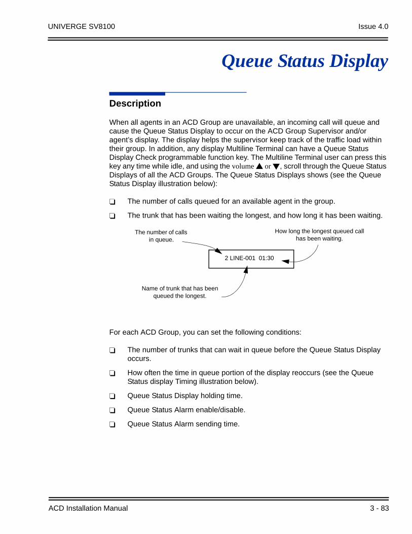
UNIVERGE SV8100 Issue 4.0
Queue Status Display
Description
When all agents in an ACD Group are unavailable, an incoming call will queue and cause the Queue Status Display to occur on the ACD Group Supervisor and/or agent’s display. The display helps the supervisor keep track of the traffic load within their group. In addition, any display Multiline Terminal can have a Queue Status Display Check programmable function key. The Multiline Terminal user can press this key any time while idle, and using the volume or , scroll through the Queue Status Displays of all the ACD Groups. The Queue Status Displays shows (see the Queue Status Display illustration below):
The number of calls queued for an available agent in the group.
The trunk that has been waiting the longest, and how long it has been waiting.
For each ACD Group, you can set the following conditions:
The number of trunks that can wait in queue before the Queue Status Display occurs.
How often the time in queue portion of the display reoccurs (see the Queue Status display Timing illustration below).
Queue Status Display holding time.
Queue Status Alarm enable/disable.
Queue Status Alarm sending time.
2 LINE-001 01:30
How long the longest queued call has been waiting.
Name of trunk that has been queued the longest.
The number of calls in queue.
ACD Installation Manual 3 - 83

Issue 4.0 UNIVERGE SV8100
Conditions
Do not use number of calls in queue and time in queue to set the ACD queue alarm. Select either one or the other for the system to follow.
If a telephone is not idle, the Queue Status Display Programmable Function key cannot be used.
The Queue Status Display is not shown and the Queue Alarm is not heard by ACD agents active on a call or those in Off-Duty mode.
In order to scroll through the ACD groups queue status, the Queue Status Display Programmable Function key must be used. You cannot scroll when the Queue Status Display appears due to an alarm condition.
If the Queue Status display and alarm are active and the queued called is answered/disconnected, the display and alarm will continue until the timers in Program 41-15-02 or 41-20-05 expire.
When an overflowed call is in queue, the call will be included in its original ACD group’s queue and not in the group’s queue to which it overflowed.
The Queue Status is not displayed on a supervisor’s phone based on the settings in Programs 41-02-xx. The supervisor must use the Queue Status Display Programmable Function key to view the queue.
41-20-02
41-20-05
41-20-02
41-20-03
41-20-05
41-20-031
3
5
6
41-20-02
41-20-05
41-20-02
41-20-03
41-20-05
41-20-031
2
3
4
5
6
Queue Status displays and Alarm Send (41-20-05) starts.
Queue Status Display ends.
Time in queue refreshes on display and queue alarm sounds, if enabled.
Call queues and 41-20-03 starts.
Pattern repeats.Alarm ends.
3 - 84

UNIVERGE SV8100 Issue 4.0
Default Setting
No Queue Status Display Check keys programmed (Program 15-07-01: *19).
Queue Status Display and Queue Alarm disabled (Program 41-20-01 = 0).
Programming
15-07-01 Programmable Function Keys
Assign a Queue Status Display Check key, if required for an ACD agent (code: *19).
20-06-01 Class of Service for Extensions
Assign a Class of Service (1~15) to an extension.
20-13-39 Class of Service Options (Supplementary Service) – ACD Queue Status Display
Turns Off (0) or On (1) the ACD Queue Status Display for an extension Class of Service. Any extension which has this option enabled also hears the queue alarm.
41-15-01 ACD Queue Alarm Information – Number of Calls in ACD Queue to Activate Alarm Information
For each ACD Group (01~64), determine the number of calls required in queue to activate the alarm (0~200).
Do not use this program if the alarm options are defined in Program 41-20-01 through Program 41-20-05.
41-15-02 ACD Queue Alarm Information – Interval Time of Alarm Information
For each ACD Group (01~64), determine the interval for displaying the alarm information (0~64800 seconds).
Do not use this program if the alarm options are defined in Program 41-20-01 through Program 41-20-05.
ACD Installation Manual 3 - 85
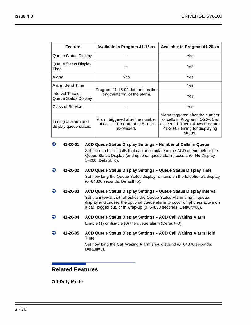
Issue 4.0 UNIVERGE SV8100
41-20-01 ACD Queue Status Display Settings – Number of Calls in Queue
Set the number of calls that can accumulate in the ACD queue before the Queue Status Display (and optional queue alarm) occurs (0=No Display, 1~200; Default=0).
41-20-02 ACD Queue Status Display Settings – Queue Status Display Time
Set how long the Queue Status display remains on the telephone’s display (0~64800 seconds; Default=5).
41-20-03 ACD Queue Status Display Settings – Queue Status Display Interval
Set the interval that refreshes the Queue Status Alarm time in queue display and causes the optional queue alarm to occur on phones active on a call, logged out, or in wrap-up (0~64800 seconds; Default=60).
41-20-04 ACD Queue Status Display Settings – ACD Call Waiting Alarm
Enable (1) or disable (0) the queue alarm (Default=0).
41-20-05 ACD Queue Status Display Settings – ACD Call Waiting Alarm Hold Time
Set how long the Call Waiting Alarm should sound (0~64800 seconds; Default=0).
Related Features
Off-Duty Mode
Feature Available in Program 41-15-xx Available in Program 41-20-xx
Queue Status Display --- Yes
Queue Status Display Time
--- Yes
Alarm Yes Yes
Alarm Send TimeProgram 41-15-02 determines the
length/interval of the alarm.
Yes
Interval Time of Queue Status Display
Yes
Class of Service --- Yes
Timing of alarm and display queue status.
Alarm triggered after the number of calls in Program 41-15-01 is
exceeded.
Alarm triggered after the number of calls in Program 41-20-01 is
exceeded. Then follows Program 41-20-03 timing for displaying
status.
3 - 86

UNIVERGE SV8100 Issue 4.0
Operation
When Logged Into ACD Group
1. With an idle multiline terminal, press the Queue Status Display Programmable Function Key (Program 15-07-01 or SC 752: code *19).
The display indicates the number of calls in queue, the trunk name, and the length of time the call has been waiting.
When the Queue Status Display key is pressed, the queue status of the extension’s group is displayed. When the extension is not in an ACD group, the Queue Status of group 1 is displayed instead.
When an agent logs in using an AIC code, the Queue Status of the default ACD group defined in Program 41-18-02 is displayed.
2. Press the volume or to scroll through the Queue Status Displays of all the ACD Groups.
3. Press the Exit key to return the phone to an idle state.
When Logged Out of ACD Group
When ACD agents are logged out and a call is placed into the ACD queue, the telephones of the logged out agents will display the Queue Status and hear the alarm according to the settings defined in system programming.
Pressing the Queue Status Display Programmable Function key will return the telephone to idle until the timer in Program 41-20-03 expires again.
ACD Installation Manual 3 - 87

Issue 4.0 UNIVERGE SV8100
THIS PAGE INTENTIONALLY LEFT BLANK
3 - 88
UNIVERGE SV8100 Issue 4.0
Supervisor, ACD Group
Description
You can designate an extension in an ACD Group to be the group's supervisor. Once assigned as an ACD Group Supervisor, the user can:
Take the entire ACD Group out of service (outside callers will hear ringback or the ACI recording).
Check the log out status of each agent after the group taken down.
Restore the ACD Group to service.
During programming, you can choose one of three modes of operation for each ACD Group supervisor:
Supervisor's extension cannot receive calls to the ACD Group (mode 0).
Supervisor's extension can only receive ACD Group calls during overflow conditions (mode 1).
Supervisors extension receives calls just like any other ACD Group agent (mode 2).
An ACD Group can have only one supervisor. In addition, an extension can be a supervisor for only one ACD Group. There are 64 available ACD Groups.
Conditions
An extension can have supervisory capabilities only while it is logged into the ACD Group.
An Out of Service Function Key (Program 15-07-01 or SC 752: code *14) will take the assigned group out of service.
A supervisor can not log in/out an AIC member as they are not normal ACD agents.
An extension assigned as an ACD Group Supervisor cannot also be a System Supervisor.
Default Setting
ACD Supervisors not programmed.
ACD Installation Manual 3 - 89
Issue 4.0 UNIVERGE SV8100
Programming
15-07-01 Programmable Function Keys
Assign the following function keys to the ACD Group Supervisor:
ACD Log In/Log Out key (code *10) for one-button Log In/Log Out operation.
Out of Service key (code *14) for removing the entire ACD Group from service.
41-04-01 ACD Group Supervisor – Group Supervisor Extension
For each ACD Group (1~64), assign the Group Supervisor's extension. (You cannot use the port entered in this program in Program 41-01-01 as a System Supervisor.)
41-04-02 ACD Group Supervisor – Operation Type
For each ACD Group (1~64), assign the operating mode for the Group Supervisor. Operating modes are 0 [do not receive ACD calls (no)], 1 [receive ACD incoming calls in case of overflow (Busy)] and 2 [receive ACD incoming calls all the time (Yes)].
Related Features
Supervisor, DSS Console
Supervisor, System
Operation
Logging On to the ACD Group
To log your supervisor extension into the ACD Group:
You only have Group Supervisor capability while logged into the ACD Group. Your display shows: WAIT ACD LOGIN
1. Press the Speaker key.
2. Dial 5.
You hear confirmation tone.
- OR -
3 - 90
UNIVERGE SV8100 Issue 4.0
Press ACD Log On/Off key (Program 15-07-01 or SC 752: code *10). Your Log On/Off key lights and you hear a single beep.
Your display will show the ACD Group to which you are logged in.
To log your supervisor extension out of an ACD Group:
This will end your Group Supervisor capabilities. Your Log On/Off key will be on and your display shows the ACD Group to which you are logged in.
1. Press the Speaker key.
2. Dial 5.
- OR -
Press ACD Log On/Off key (Program 15-07-01 or SC 752: code *10).
Your display shows: ACD LOGOUT (1:Yes, 0:No)
3. Dial 1 to log out.
You hear confirmation tone (if you dialed *5) or a single beep (if you pressed the ACD Log On/Log Off key).
Dial 0 instead to cancel the log out and return to the group.
Taking an ACD Group out of Service
To take your entire ACD Group out of service:
You must be logged into the group.
1. Press your Out of Service key (Program 15-07-01 or SC 752: code *14).
Your display shows: END OF WORK? (1:Yes,0:No)
2. Dial 1 to take your entire ACD Group out of service.
The Log On/Off and Out of Service keys light. While you are logged out, calls no longer ring into the ACD Group.
Your display shows: G:n END OF WORK! TERMINAL LOG OUT... indicating that all agents have not yet logged out of the group.
Dial 0 instead to cancel and return to the group.
To check to see which agents have not yet logged out of the ACD Group:
Your display shows: G:n END OF WORK! TERMINAL LOG OUT...
1. Press your ACD Log On/Off key (Program 15-07-01 or SC 752: code *10).
Your display shows: LOGIN TERMINAL n CHECK SAT non
The extension shown in CHECK SAT non has not logged out.
2. Press volume or to scroll through the list of agents that have not logged out.
When all agents have logged out (including yourself), your display shows:
ACD Installation Manual 3 - 91

Issue 4.0 UNIVERGE SV8100
3. Press ACD Log On/Off key (Program 15-07-01 or SC 752: code *10) again.
Your displays shows: GROUP No:n
To return the ACD Group to service:
The Out of Service and Log On/Off keys are lit. If you have logged out of the group and your ACD Log On/Off key is out, you must log back in before going to step 1.
1. Press your Out of Service key (Program 15-07-01 or SC 752: code *14).
The key goes out and your agents can log back into the group.
Logging Agents into and out of their ACD Group
To log an agent into their ACD Group:
You can do this while either logged in or logged out.
1. Press the Speaker key.
2. Dial 667.
3. Dial the ACD Agent's extension number.
You hear confirmation tone.
4. Press Speaker to hang up.
To log an agent out of their ACD Group:
You can do this while either logged in or logged out.
1. Press the Speaker key.
2. Dial 668.
3. Dial the ACD Agent's extension number.
You hear confirmation tone.
4. Press Speaker to hang up.
Assigning Agents to different ACD Groups
To assign an agent to a different ACD Group:
You can do this while either logged in or logged out. You must log out the ACD Agent before reassigning them.
1. Press the Speaker key.
2. Dial 669.
3 - 92

UNIVERGE SV8100 Issue 4.0
3. Dial the ACD Agent's extension number.
4. Dial the number of the ACD Group to which you want to assign the agent.
You hear confirmation tone.
5. Press Speaker to hang up.
ACD Installation Manual 3 - 93

Issue 4.0 UNIVERGE SV8100
THIS PAGE INTENTIONALLY LEFT BLANK
3 - 94

UNIVERGE SV8100 Issue 4.0
Supervisor, ACD System
Description
You can designate an extension as an ACD System Supervisor. The system can have only one ACD System Supervisor.
Once a user is assigned as an ACD System Supervisor, he can perform the following tasks:
Take all the system's ACD Groups out of service simultaneously. Outside callers will hear ringback or the ACI recording.
Check the log out status of each agent after the groups are taken down.
Restore all the ACD Groups to service simultaneously.
Log an agent into or out of an ACD Group.
Reassign an agent to a different ACD Group.
Conditions
An Out of Service Function Key (Program 15-07-01 or SC 752: code *14) will take all groups out of service.
A supervisor can not log in/out an AIC member as they are not normal ACD agents.
An extension assigned as an ACD System Supervisor cannot also be an ACD Group Supervisor.
Default Setting
ACD System Supervisors not programmed.
Programming
11-13-10 Service Code Setup (for ACD) – ACD Agent Login by Supervisor
This Service Code (normally 667) allows the System Supervisor to log an agent back into an ACD Group.
ACD Installation Manual 3 - 95

Issue 4.0 UNIVERGE SV8100
11-13-11 Service Code Setup (for ACD) – ACD Agent Logout by Supervisor
This Service Code (normally 668) allows the System Supervisor to log an agent out of an ACD Group.
11-13-12 Service Code Setup (for ACD) – Change Agent ACD Group by Supervisor
This Service Code (normally 669) allows the System Supervisor to assign an agent to a different ACD Group.
15-07-01 Programmable Function Keys
Assign the following function keys to the ACD Group Supervisor:
ACD Log In/Log Out key (code *10) for one-button Log In/Log Out operation. The System Supervisor must have a Log In/Log Out key.
Out of Service key (code *14) for removing the entire ACD Group from service.
20-06-01 Class of Service for Extensions
Assign a Class of Service (1~15) to an extension.
20-13-33 Class of Service Options (Supplementary Service) – ACD Supervisor’s Position Enhancement
In an extension's Class of Service, enable this option (1) to allow the System Supervisor to change the login and ACD Group assignment for an agent. This option also allows agents to change their own ACD Group assignment.
41-01-01 System Options for ACD – System Supervisory Extension
Assign an extension as the ACD System Supervisor.
41-04-01 ACD Group Supervisor – Group Supervisor Extension
For each ACD Group (1~64), assign the Group Supervisor's extension. (You cannot use the port entered in this program in Program 41-01-01 as a System Supervisor.)
41-04-02 ACD Group Supervisor – Operation Type
For each ACD Group (1~64), assign the operating mode for the Group Supervisor. Operating modes are 0 [do not receive ACD calls (no)], 1 [receive ACD incoming calls in case of overflow (Busy)] and 2 [receive ACD incoming calls all the time (Yes)].
Related Features
Supervisor, ACD Group
Supervisor, DSS Console
3 - 96
UNIVERGE SV8100 Issue 4.0
Operation
Logging on as the ACD System Supervisor
To log on as the ACD System Supervisor:
You only have System Supervisor capability while logged on.
1. Press the Speaker key.
2. Dial 5.
You hear confirmation tone.
- OR -
Press ACD Log On/Off key (Program 15-07-01 or SC 752: code *10).
Your Log On/Off key lights and you hear a single beep.
Your display will show: SUPERVISOR.
Logging off as the ACD System Supervisor
To log off as the ACD System Supervisor:
This will end your System Supervisor capabilities. Your Log On/Off key is lit and your display shows: SUPERVISOR
1. Press the Speaker key.
2. Dial 5.
- OR -
Press ACD Log On/Off key (Program 15-07-01 or SC 752: code *10). Your display shows: ACD LOGOUT (1:Yes, 0:No)
3. Dial 1 to log out.
You hear confirmation tone (if you dialed *5) or a single beep (if you pressed the ACD Log On/Log Off key) and the Log On/Off key goes out.
Dial 0 instead to cancel the log out.
Taking all the ACD Groups Simultaneously Out Of Service
To take all your ACD Groups out of service:
You must be logged on as the ACD System Supervisor.
1. Press your Out of Service key (Program 15-07-01 or SC 752: code *14).
Your display shows: END OF WORK? (1:Yes,0:No)
ACD Installation Manual 3 - 97

Issue 4.0 UNIVERGE SV8100
2. Dial 1 to take all the ACD Groups out of service.
The Log On/Off and Out of Service keys light. While you are logged out, calls no longer ring into the ACD Groups.
Your display shows: G:n END OF WORK! TERMINAL LOG OUT... indicating that all agents have not yet logged out of the group.
Dial 0 instead to cancel and return to the group.
To check to see which agents have not yet logged out of their ACD Group:
Your display shows: END OF WORK! TERMINAL LOG OUT...
1. Press your ACD Log On/Off key (Program 15-07-01 or SC 752: code *10).
Your display shows: LOGIN TERMINAL n CHECK STA nnn
The extension shown in CHECK STA nnn has not logged out.
2. Press volume or to scroll through the list of agents that have not logged out.
3. Press ACD Log On/Off key (Program 15-07-01 or SC 752: code *10) again.
Your displays shows: SUPERVISOR
To return all the ACD Groups to service:
The Out of Service and Log On/Off keys are lit. If you have logged out as an ACD System Supervisor (and your ACD Log On/Off key is out), you must log back in before going to step 1.
1. Press your Out of Service key (Program 15-07-01 or SC 752: code *14).
The key goes out and your agents can log back into the group.
Logging Agents into and out of their ACD Group
To log an agent into their ACD Group:
You can do this while either logged in or logged out.
1. Press the Speaker key.
2. Dial 667.
3. Dial the ACD Agent's extension number.
You hear confirmation tone.
4. Press Speaker to hang up.
3 - 98

UNIVERGE SV8100 Issue 4.0
To log an agent out of their ACD Group:
You can do this while either logged in or logged out.
1. Press the Speaker key.
2. Dial 668.
3. Dial the ACD Agent's extension number.
You hear confirmation tone.
4. Press Speaker to hang up.
Assigning Agents to different ACD Groups
To assign an agent to a different ACD Group:
You can do this while either logged in or logged out. You must log out the ACD Agent before reassigning them.
1. Press the Speaker key.
2. Dial 669.
3. Dial the ACD Agent's extension number.
4. Dial the number of the ACD Group to which you want to assign the agent.
You hear confirmation tone.
5. Press Speaker to hang up.
ACD Installation Manual 3 - 99

Issue 4.0 UNIVERGE SV8100
THIS PAGE INTENTIONALLY LEFT BLANK
3 - 100
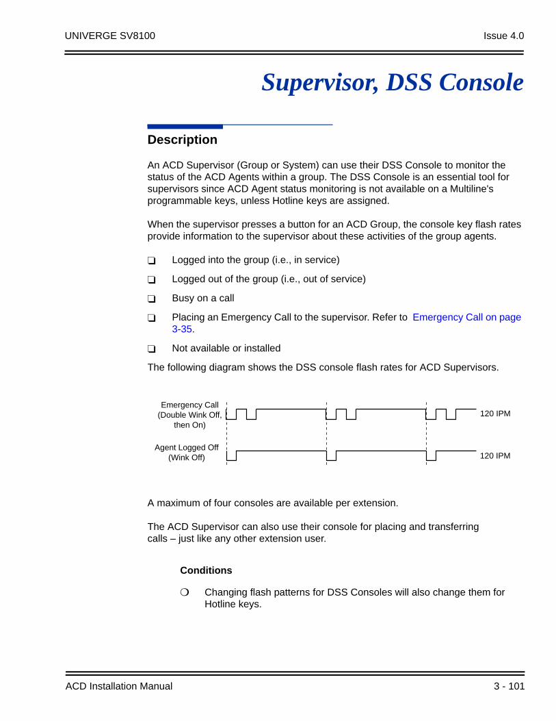
UNIVERGE SV8100 Issue 4.0
Supervisor, DSS Console
Description
An ACD Supervisor (Group or System) can use their DSS Console to monitor the status of the ACD Agents within a group. The DSS Console is an essential tool for supervisors since ACD Agent status monitoring is not available on a Multiline's programmable keys, unless Hotline keys are assigned.
When the supervisor presses a button for an ACD Group, the console key flash rates provide information to the supervisor about these activities of the group agents.
Logged into the group (i.e., in service)
Logged out of the group (i.e., out of service)
Busy on a call
Placing an Emergency Call to the supervisor. Refer to Emergency Call on page 3-35.
Not available or installed
The following diagram shows the DSS console flash rates for ACD Supervisors.
A maximum of four consoles are available per extension.
The ACD Supervisor can also use their console for placing and transferringcalls – just like any other extension user.
Conditions
Changing flash patterns for DSS Consoles will also change them for Hotline keys.
Agent Logged Off(Wink Off) 120 IPM
9 2 0 - 1 4 1 a
Emergency Call(Double Wink Off, then On)
120 IPMEmergency Call
(Double Wink Off, then On)
120 IPM
Agent Logged Off (Wink Off) 120 IPM
ACD Installation Manual 3 - 101

Issue 4.0 UNIVERGE SV8100
If an extension has four DSS Consoles connected, program one of the consoles for Direct Line Selection (i.e., placing and answering outside calls).
A DSS Console requires a separate digital station port.
When installing a DSS, the system must auto-detect the console in order for the LEDs to function correctly. When connecting the DSS to an extension previously defined with another circuit type, undefine the circuit type (enter 00 in Program 10-03-01 for the extension number), then connect the DSS console.
Default Setting
No DSS Consoles assigned (in Program 32-02-01).
All DSS Console key ranges are ports 1~200.
Programming
30-01-01 DSS Console Operating Mode
Set the mode of the system’s DSS Consoles. The entry you make in this option applies to all the system’s DSS Consoles. The available options are Regular (Business) Mode (0), Hotel Mode (1), ACD Monitor Mode (2) and Business/ACD Mode (3).
30-02-01 DSS Console Extension Assignment – Extension Number
Designate the DSS Console installations (i.e., the extensions that have DSS Consoles connected to them).
30-03-01 DSS Console Key Assignment
Check this program to make sure that DSS Console keys assigned to ACD Agents are programmed as DSS keys.
30-04-01 DSS Console Alternate Answer – DSS Console Alternate Answer
If the console should have Alternate Answering, use this program to assign the Alternate Answering Destination.
Caution
You must exit programming and reset your system before DSS Console programming for ACD Supervisors will take effect.
3 - 102
UNIVERGE SV8100 Issue 4.0
Related Features
Door Box
Paging, External
Paging, Internal
Night Service
Operation
To call an ACD Agent from your ACD Supervisor's DSS Console:
1. Press DSS Console ACD Group key to select the agents group.
2. Press DSS console key for agent.
If the call voice-announces, you can make it ring by dialing 1. Or, if the call rings, you can make it voice-announce by dialing 1.
To Transfer a call to an ACD Agent from your Supervisor's DSS Console:
1. Place or answer call.
If you are on an Intercom call, press the Hold key before going to the next step.
2. Press DSS Console ACD Group key to select the agents group.
3. Press DSS key for the ACD Agent that will receive transfer.
You cannot Transfer to an agent that is in Off-Duty Mode or in Do Not Disturb.
ACD Agent Busy Lamp Field
When the DSS key flash rate is . . . The ACD Agent is . . .
OFF Not installed and/or programmed
ON Busy on a call
Double Wink On(Agent Logged On rate)
Logged Onto ACD Group
Wink Off(Agent Logged Off rate)
Logged out of ACD Group or in Off-Duty Mode
Fast Flash(Emergency Call)
Placing an Emergency Call to the supervisor
ACD Installation Manual 3 - 103

Issue 4.0 UNIVERGE SV8100
4. (Optional) Announce call.
If the called agent does not want the call, press the flashing line key to retrieve it.
5. Press Speaker to hang up.
3 - 104
UNIVERGE SV8100 Issue 4.0
Supervisor Monitor / ACD Monitor
Description
Supervisor Monitor (ACD Monitor) allows an ACD System or Group Supervisor with a uniquely programmed ACD Monitor key to listen in on an ACD Agent's call. The ACD Agent and the outside caller are unaware that their call is being monitored. ACD Monitor helps supervisors that want to make spot checks on an ACD Agent's performance. This encourages agents to always provide the highest levels of courtesy and performance since the supervisor can listen in unobtrusively at any time.
Conditions
None
Default Setting
An extension automatically sends off hook signals to a busy extension (Program 20-13-06 = 1). The caller does not hear busy tone.
No ACD Monitor keys assigned (Program 15-07-01: *15).
Programming
15-07-01 Programmable Function Keys
Assign an ACD Monitor key (code *15) to each supervisor that should be able to monitor an ACD Agent's call.
20-02-05 System Options for Multiline Telephones – Headset Busy Mode
Set this option to 0 for all ACD Agents with headsets that should be monitored. This makes the headset extension busy when only one extension appearance is busy. The supervisor can set up ACD Monitor only if the agent's phone is busy (i.e., while the supervisor hears busy tone).
20-06-01 Class of Service for Extensions
Assign a Class of Service (1~15) to an extensions.
CautionUnauthorized intrusion on calls using this feature may be interpreted as an invasion of
privacy.
ACD Installation Manual 3 - 105

Issue 4.0 UNIVERGE SV8100
20-13-06 Class of Service Options (Supplementary Service) – Automatic Off-Hook Signaling (Automatic Override)
Allows a busy extension ability to manually (0) or automatically (1) receive off-hook signals.
Related Features
Supervisor, ACD Group
Supervisor, ACD System
Operation
To monitor an ACD Agent's call:
Only ACD Supervisors (Group or System) can use ACD Monitor.
1. Call the busy ACD Agent.
You must hear busy tone.
2. Press your ACD Monitor Key (Program 15-07-01 or SC 752: *15).
Your ACD Monitor Key lights.
You hear the agent's conversation but the agent is not aware that you are monitoring their call.
Monitoring will continue until you press the ACD Monitor key or the ACD Agent hangs up. For example, if the agent places a call on Hold but does not hang up, you will hear Music on Hold.
To stop monitoring an ACD Agent's call:
1. Press the lit ACD Monitor Key (Program 15-07-01 or SC 752: *15).
Monitoring also stops when the ACD Agent hangs up.
3 - 106
UNIVERGE SV8100 Issue 4.0
Traffic Reports
Description
The system provides the ability to send data to a PC connected to the UNIVERGE SV8100. The telephone call traffic data for each extension is captured for use with the SMDR feature.
Call Traffic
The total of outgoing call frequency, outgoing call duration, call charge, incoming call frequency, answer frequency, incoming call duration, ringing duration, and abandon call frequency for each extension is logged. The total of incoming calls, answer frequency, call duration, and abandon call frequency of each called party number is logged and the data is outputted to the PC. The system totals the hour, day, week, and month for each terminal and trunk number. This information is used by the SMDR feature. The extension which is totaled is determined by system programming. The system outputs this data to the PC for the total period.
Conditions
The SMDR call buffer stores 500 calls. The buffer stores calls when the SMDR device is unavailable. When the buffer fills, the oldest record is deleted to allow the new record to be saved.
If connected to the output device, the reports will print hourly. If not connected and the data is not outputted at the end of the hour, the traffic data will be overwritten by new incoming data.
The traffic data is lost if a power failure occurs.
Default Setting
Disabled
ACD Installation Manual 3 - 107
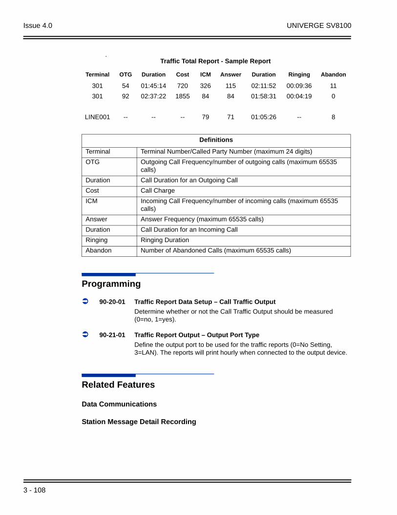
Issue 4.0 UNIVERGE SV8100
.
Programming
90-20-01 Traffic Report Data Setup – Call Traffic Output
Determine whether or not the Call Traffic Output should be measured (0=no, 1=yes).
90-21-01 Traffic Report Output – Output Port Type
Define the output port to be used for the traffic reports (0=No Setting, 3=LAN). The reports will print hourly when connected to the output device.
Related Features
Data Communications
Station Message Detail Recording
Traffic Total Report - Sample Report
Terminal OTG Duration Cost ICM Answer Duration Ringing Abandon
301 54 01:45:14 720 326 115 02:11:52 00:09:36 11
301 92 02:37:22 1855 84 84 01:58:31 00:04:19 0
LINE001 -- -- -- 79 71 01:05:26 -- 8
Definitions
Terminal Terminal Number/Called Party Number (maximum 24 digits)
OTG Outgoing Call Frequency/number of outgoing calls (maximum 65535 calls)
Duration Call Duration for an Outgoing Call
Cost Call Charge
ICM Incoming Call Frequency/number of incoming calls (maximum 65535 calls)
Answer Answer Frequency (maximum 65535 calls)
Duration Call Duration for an Incoming Call
Ringing Ringing Duration
Abandon Number of Abandoned Calls (maximum 65535 calls)
3 - 108

UNIVERGE SV8100 Issue 4.0
Operation
Operation is automatic once programmed.
ACD Installation Manual 3 - 109

Issue 4.0 UNIVERGE SV8100
THIS PAGE INTENTIONALLY LEFT BLANK
3 - 110

UNIVERGE SV8100 Issue 4.0
Wrap-Up Time
Description
Wrap-Up Time temporarily busies-out an ACD agent's phone from receiving ACD calls so they can work at their desk uninterrupted, although other types of calls can still be received. This gives the agent time to fill out important logs and records as soon as they are finished with their call. There are two types of Wrap-Up Time:
Manual Wrap-Up Time
An ACD Agent can enable Manual Wrap-Up Time any time they need to work at their desk undisturbed. You might prefer this Wrap-Up Time mode if an agent only occasionally has to fill out follow-up paper work after they complete their call. When the agent is through catching up with their work, they manually return themselves to the ACD Group.
Automatic Wrap-Up Time
The system implements Automatic Wrap-Up Time for the agent as soon as they hang up their current call. This is helpful in applications (such as Tech Service groups) where follow-up paperwork is a requirement for every call. When the agent is done with their work, they manually return themselves to the ACD Group. Optionally, Auto Wrap-up can automatically log the agent back into their group after a programmed interval (termed the Auto Wrap-up Time).
Conditions
None
Default Setting
Service Code to set Wrap-Up Mode for SLT is 656 (Program 11-13-03).
Service Code to cancel Wrap-Up Mode for SLT is 657 (Program 11-13-04).
No Wrap-Up Time keys programmed (Program 15-07-01 = *17).
Automatic Wrap-Up disabled (Program 41-14-02 = 0).
Auto Wrap-Up Time disabled (Program 41-14-09 = 0).
ACD Installation Manual 3 - 111
Issue 4.0 UNIVERGE SV8100
Programming
11-13-03 Service Code Setup (for ACD) – Set ACD Wrap-Up Time (for SLT)
Assign the service code to be used by a single line telephone user to enter Wrap-Up mode.
11-13-04 Service Code Setup (for ACD) – Cancel ACD Wrap-Up Time (for SLT)
Assign the service code to be used by a single line telephone user to cancel Wrap-Up mode.
15-07-01 Programmable Function Keys
If extension should have Wrap-Up Time capability, assign a Wrap-Up Time programmable key (code *17).
41-14-02 ACD Options Setup – Automatic Wrap Up Mode
Set the Wrap Up Mode option (0=After wrap up mode key is pressed, 1=After call is finished automatically) for ACD Groups (01~64).
41-14-09 ACD Options Setup – Automatic Wrap-Up End Time
For each ACD Group (01~64), set how long the system waits before automatically ending wrap up time. After this interval expires, Auto Wrap-Up will automatically log the agent back into their group. To disable the Auto Wrap-up option, enter 0 (0=disabled, 1~64800 seconds).
Related Features
Off-Duty Mode
Operation
To activate Wrap-Up Time:
Your ACD Group setup may automatically activate Off-Duty Mode after you complete a call. If you group has Automatic Wrap-Up Time, your Wrap-Up Time key flashes while you are on a call. In addition, Auto Wrap-up may automatically return you to your ACD Group after a preset time.
3 - 112
UNIVERGE SV8100 Issue 4.0
Multiline
1. Press your Wrap-Up Time Key (Program 15-07-01 or SC 752: *17).
Your Wrap-Up Time Key lights.
When you activate Wrap-Up Time, your ACD Supervisor with a DSS Console sees your extension as busy (i.e., your key is lit).
Single Line Telephone
1. Lift the handset.
2. Dial 656.
You hear a fast busy.
When you activate Wrap-Up Time, your ACD Supervisor with a DSS Console sees your extension as busy (i.e., your key is lit).
To cancel Wrap-Up Time:
Multiline
1. Press your Wrap-Up Time Key (Program 15-07-01 or SC 752: *17).
When you deactivate Wrap-Up Time, your ACD Supervisor with a DSS Console sees your extension as available (logged in).
Single Line Telephone
1. Lift the handset.
2. Dial 657.
You hear a confirmation tone.
When you deactivate Wrap-Up Time, your ACD Supervisor with a DSS Console sees your extension as available (logged in).
ACD Installation Manual 3 - 113

Issue 4.0 UNIVERGE SV8100
THIS PAGE INTENTIONALLY LEFT BLANK
3 - 114
Pro
gra
mm
ing
4
ProgrammingSECTION 1 BEFORE YOU START PROGRAMMING
This chapter provides detailed information about the system programs. By changing a program, you change the way the feature associated with that program works. In this chapter, you find out about each program, the features that the program affects and how to enter the program data into system memory.
SECTION 2 HOW TO USE THIS CHAPTER
This chapter lists each program in numerical order. For example, Program 10-01 is at the beginning of the section and Program 92-01 is at the end. The information on each program is subdivided into the following headings:
Description describes what the program options control. The Default Settings for each program are also included. When you first install the system, it uses the Default Setting for all programs. Along with the Description are the Conditions which describe any limits or special considerations that may apply to the program.
The reverse type (white on black) just beneath the Description heading is the program access level. You can only use the program if your access level meets or exceeds the level the program requires. Refer to Section 4 How to Enter and Exit Programming Mode on page 4-3 for a list of the system access levels and passwords.
Feature Cross Reference provides you with a table of all the features affected by the program. You may want to keep the referenced features in mind when you change a program. Customizing a feature may have an effect on another feature that you did not intend.
Do not start customizing your system before reading Chapter Setting Up ACD for the First Time on page 2-1.
ACD Installation Manual 4 - 1
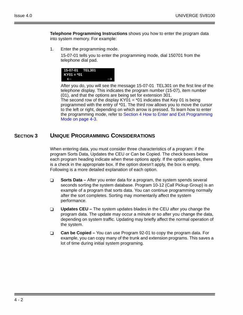
Issue 4.0 UNIVERGE SV8100
Telephone Programming Instructions shows you how to enter the program data into system memory. For example:
1. Enter the programming mode.
15-07-01 tells you to enter the programming mode, dial 150701 from the telephone dial pad.
After you do, you will see the message 15-07-01 TEL301 on the first line of the telephone display. This indicates the program number (15-07), item number (01), and that the options are being set for extension 301.The second row of the display KY01 = *01 indicates that Key 01 is being programmed with the entry of *01. The third row allows you to move the cursor to the left or right, depending on which arrow is pressed. To learn how to enter the programming mode, refer to Section 4 How to Enter and Exit Programming Mode on page 4-3.
SECTION 3 UNIQUE PROGRAMMING CONSIDERATIONS
When entering data, you must consider three characteristics of a program: if the program Sorts Data, Updates the CEU or Can be Copied. The check boxes below each program heading indicate when these options apply. If the option applies, there is a check in the appropriate box. If the option doesn’t apply, the box is empty. Following is a more detailed explanation of each option.
Sorts Data – After you enter data for a program, the system spends several seconds sorting the system database. Program 10-12 (Call Pickup Group) is an example of a program that sorts data. You can continue programming normally after the sort completes. Sorting may momentarily affect the system performance.
Updates CEU – The system updates blades in the CEU after you change the program data. The update may occur a minute or so after you change the data, depending on system traffic. Updating may briefly affect the normal operation of the system.
Can be Copied – You can use Program 92-01 to copy the program data. For example, you can copy many of the trunk and extension programs. This saves a lot of time during initial system programing.
15-07-01 TEL301KY01 = *01
4 - 2

UNIVERGE SV8100 Issue 4.0
SECTION 4 HOW TO ENTER AND EXIT PROGRAMMING MODE
4.1 Entering Programming Mode
To enter programming mode:
1. Go to any working display telephone.
In a newly installed system, use extension 101 (port 1).
2. Do not lift the handset.
3. Press Speaker.
4. # * # *
5. Dial the system password + Transfer.
Refer to the following table for the default system passwords. To change the passwords, use Program 90-02-01.
Password
PasswordUser Name
Level Programs at this Level
47544 necii 1 (MF) All programs
12345678 tech 2 (IN) All programs in this section not listed below for SA and SB
0000 ADMIN1 3 (SA)
10-01, 10-02, 10-12, 10-13, 10-14, 10-15, 10-16, 10-17, 10-18, 10-22, 12-02, 12-03, 12-04, 15-01, 15-07, 15-09, 15-10, 15-11, 20-16, 21-07, 21-14, 22-04, 22-11, 25-08, 30-03, 32-02, 40-02, 41-02, 41-03, 41-04, 41-05, 41-06, 41-07, 41-08, 41-09, 41-10, 41-11, 41-12, 41-13, 41-14, 41-15, 41-16, 41-17, 41-18, 90-03, 90-04, 90-06, 90-07, 90-18, 90-19
9999 ADMIN2 4 (SB) 13-04, 13-05, 13-06
ACD Installation Manual 4 - 3

Issue 4.0 UNIVERGE SV8100
4.2 Exiting Programming Mode
To exit programming mode:
When you are done programming, you must be out of a program options to exit. Press Answer to exit the program option.
1. Press Answer to exit the program options, if needed.
2. Press Speaker. You see, Saving System Data if changes to system programming are made.
3. The display shows Complete Data Save when completed and exits the phone to idle mode.
Program ModeBase Service OP1 OP2
4 - 4

UNIVERGE SV8100 Issue 4.0
SECTION 5 USING KEYS TO MOVE AROUND IN THE PROGRAMS
Once you enter the programming mode, use the keys in the following chart to enter data, edit data and move around in the menus.
Use this key... When you want to. . .
0~9, and # Enter data into a program.
TransferComplete the programming step you just made. When a program entry displays, press Transfer to bypass the entry without changing it.
Recall Delete the entry to the left.
Answer
Exit one step at a time from the program window currently being viewed.
For example, if you’re programming item 5 in 15-03, press Answer to enter a new option in program 15-03. Press Answer again to select a new program in the 15- series. Press Answer a third time to enter a new program beginning with 1. Press Answer one last time to bring you to the beginning program display, allowing you to enter any program number.
MicTo switch extension, line, etc. being programmed press Redial. The cursor moves up to the top row of the display. Press Redial again to move the cursor back to the middle row.
Line Keys
Use programmed settings to help with the program entry. These settings vary between programs from LINE 1 = 0 (off) and LINE 2 = 1 (on) to preset values for timers where LINE 1 = 5, LINE 2 = 10, LINE 3 = 15, etc.
For programs with this option, the line key which currently matches the programmed setting is On steady.
The display may also indicate Softkeys which allow you to select the values as well (-1 and +1 step through these programmed settings.)
Line Key 1 Program a pause in a Speed Dial bin.
Line Key 2 Program a recall/flash in a Speed Dial bin.
Line Key 3 Program @ in a Speed Dial bin.
Vol
Scroll backward through a list of entry numbers (e.g., from extension 101 to 102, 103, etc.) or through entries in a table (e.g., Common Permit Table).
If you enter data and press this key, the system accepts the data before scrolling forward.
Vol
Scroll forward through a list of entry numbers (e.g., from extension 101 to 102, 103, etc.) or through entries in a table (e.g., Common Permit Table).
If you enter data and press this key, the system accepts the data before scrolling backward.
ACD Installation Manual 4 - 5

Issue 4.0 UNIVERGE SV8100
SECTION 6 PROGRAMMING NAMES AND TEXT MESSAGES
Several programs (e.g., Program 20-16: Selectable Display Messages) require you to enter text. Use the following chart when entering and editing text. When using the keypad digits, press the key once for the first character, twice for the second character, etc. For example, to enter a C, press the “2” key three times. Press the key six times to display the lower case letter.
Use this keypad digit . . .
When you want to. . .
1
Enter characters: 1 @ [ ¥ ] ^ _ ‘ { | } Press repeatedly to scroll through the list. After selecting your entry, press the next letter or use the left scroll or right scroll Softkey to move the cursor.
2Enter characters: A~C, a~c, 2. After selecting your entry, press the next letter or use the left scroll or right scroll Softkey to move the cursor.
3Enter characters: D~F, d~f, 3. After selecting your entry, press the next letter or use the left scroll or right scroll Softkey to move the cursor.
4 Enter characters: G~I, g~i, 4. After selecting your entry, press the next letter or use the left scroll or right scroll Softkey to move the cursor.
5Enter characters: J~L, j~l, 5. After selecting your entry, press the next letter or use the left scroll or right scroll Softkey to move the cursor.
6Enter characters: M~O, m~o, 6. After selecting your entry, press the next letter or use the left scroll or right scroll Softkey to move the cursor.
7Enter characters: P~S, p~s, 7. After selecting your entry, press the next letter or use the left scroll or right scroll Softkey to move the cursor.
8Enter characters: T~V, t~v, 8. After selecting your entry, press the next letter or use the left scroll or right scroll Softkey to move the cursor.
9Enter characters: W~Z, w~z, 9. After selecting your entry, press the next letter or use the left scroll or right scroll Softkey to move the cursor.
0
Enter characters: 0 ! “ # $ % & ‘ ( )Press repeatedly to scroll through the list. After selecting your entry, press the next letter or use the left scroll or right scroll Softkey to move the cursor.
Enter characters: + , - . / : ; < = > ?Press repeatedly to scroll through the list. After selecting your entry, press the next letter or use the left scroll or right scroll Softkey to move the cursor.
Softkey Left/Right Arrows
Accepts an entry (only required if two letters on the same key are needed - ex: TOM) and moves cursor in the arrows direction.
CONF Clear the character entry one character at a time.
CLEAR Clear all the entries from the point of the flashing cursor and to the right.
4 - 6

UNIVERGE SV8100 Issue 4.0
SECTION 7 USING SOFTKEYS FOR PROGRAMMING
Each UNIVERGE SV8100 display telephone provides interactive Softkeys for intuitive feature access. The options for these keys automatically change depending on where you are in the system programming. Simply press the Softkey located below the option you wish and the display changes accordingly.
Pressing the volume or scrolls between the menus.
SECTION 8 WHAT THE SOFTKEY DISPLAY PROMPTS MEAN
When using a display phone in programming mode, you see various Softkey options displayed. These keys allow you to easily select, scan, or move through the programs.
Program ModeBase Service OP1 OP2
Program Mode CCIS Hard Mtnance
Softkey Display Prompts
If you press this Softkey . . . The system will. . .
back Go back one step in the program display.
You can press volume or to scroll forwards or backwards through a list of Programs.
Scroll down through the available programs.
Scroll up through the available programs.
select Select the currently displayed program.
Move the cursor to the left.
Move the cursor to the right.
-1 Move back through the available program options.
+1 Move forward through the available program options.
ACD Installation Manual 4 - 7

Issue 4.0 UNIVERGE SV8100
SECTION 9 PROGRAMMING
The remainder of this chapter provides instructions for programming individual program blocks.
4 - 8
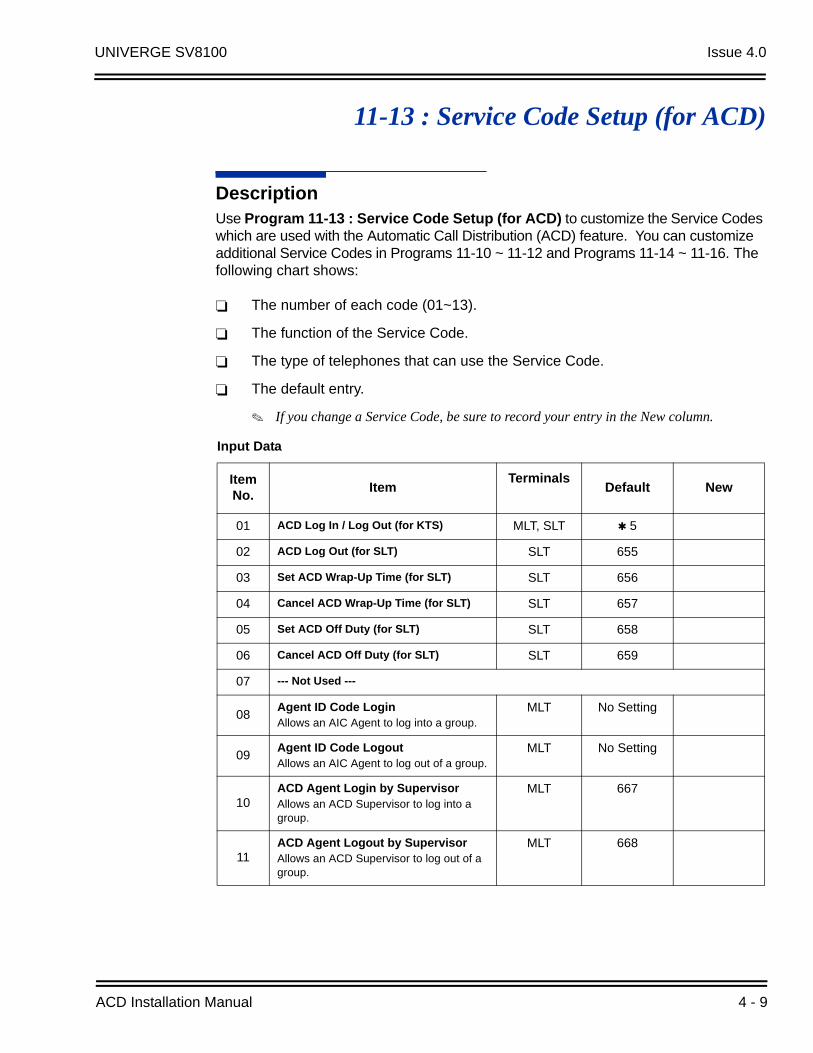
UNIVERGE SV8100 Issue 4.0
11-13 : Service Code Setup (for ACD)
DescriptionUse Program 11-13 : Service Code Setup (for ACD) to customize the Service Codes which are used with the Automatic Call Distribution (ACD) feature. You can customize additional Service Codes in Programs 11-10 ~ 11-12 and Programs 11-14 ~ 11-16. The following chart shows:
The number of each code (01~13).
The function of the Service Code.
The type of telephones that can use the Service Code.
The default entry.
If you change a Service Code, be sure to record your entry in the New column.
Input Data
Item No.
ItemTerminals
Default New
01 ACD Log In / Log Out (for KTS) MLT, SLT 5
02 ACD Log Out (for SLT) SLT 655
03 Set ACD Wrap-Up Time (for SLT) SLT 656
04 Cancel ACD Wrap-Up Time (for SLT) SLT 657
05 Set ACD Off Duty (for SLT) SLT 658
06 Cancel ACD Off Duty (for SLT) SLT 659
07 --- Not Used ---
08Agent ID Code LoginAllows an AIC Agent to log into a group.
MLT No Setting
09Agent ID Code LogoutAllows an AIC Agent to log out of a group.
MLT No Setting
10ACD Agent Login by SupervisorAllows an ACD Supervisor to log into a group.
MLT 667
11ACD Agent Logout by SupervisorAllows an ACD Supervisor to log out of a group.
MLT 668
ACD Installation Manual 4 - 9

Issue 4.0 UNIVERGE SV8100
ConditionsNone
Feature Cross Reference
Automatic Call Distribution (ACD)
Telephone Programming Instructions
To enter data for Program 11-13 [Service Code Setup (for ACD)]:
1. Enter the programming mode.
2. 11 13
3. Enter the number of the item you want to program.
12
Change Agent ACD Group by SupervisorWhen using service code 669 to change an agent ACD group, the supervisor must enter a 2-digit number for the group. For example, to change to ACD group 4, the entry would be 669 04.
MLT 669
13
ACD Agent Changing Own ACD GroupUsing this service code, an ACD Agent can reassign themselves to another ACD Group.
MLT 670
MLT = Multiline Terminal SLT = Single Line Telephone
11-13-01
KT_ACD_LogIn/Out
back select
11-13-nn
nnnnn
Input Data
Item No.
ItemTerminals
Default New
4 - 10
UNIVERGE SV8100 Issue 4.0
4. Enter data for the item you selected + Hold.
5. Enter data for the next item in the program.
- OR -
Press MSG once to enter a new item number.
- OR -
Press MSG until you exit that series programming section.
ACD Installation Manual 4 - 11

Issue 4.0 UNIVERGE SV8100
THIS PAGE INTENTIONALLY LEFT BLANK
4 - 12
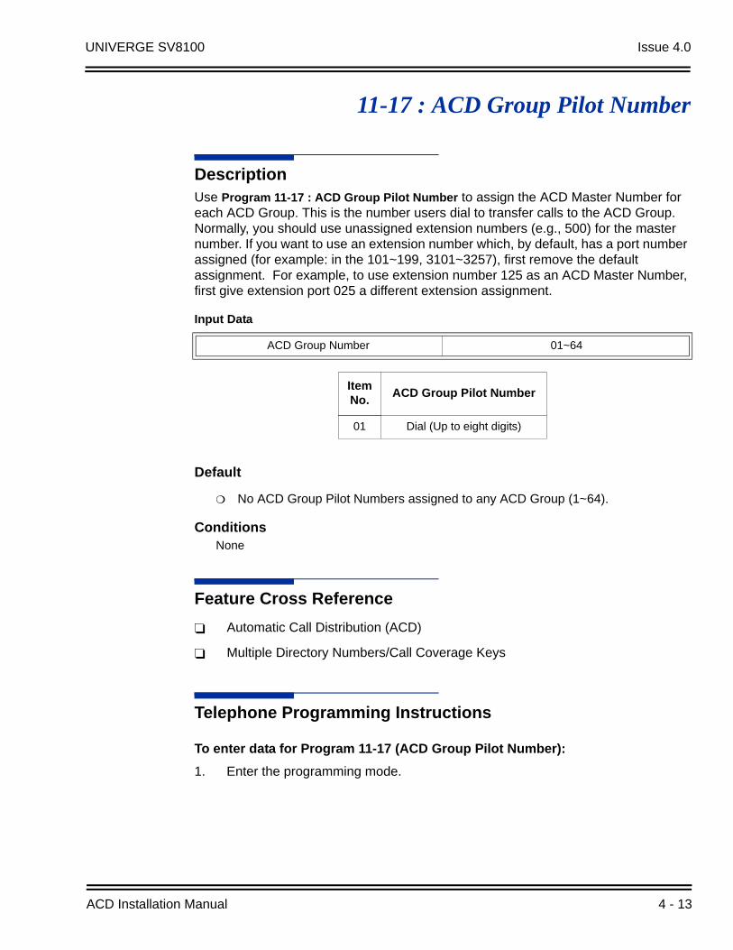
UNIVERGE SV8100 Issue 4.0
11-17 : ACD Group Pilot Number
DescriptionUse Program 11-17 : ACD Group Pilot Number to assign the ACD Master Number for each ACD Group. This is the number users dial to transfer calls to the ACD Group. Normally, you should use unassigned extension numbers (e.g., 500) for the master number. If you want to use an extension number which, by default, has a port number assigned (for example: in the 101~199, 3101~3257), first remove the default assignment. For example, to use extension number 125 as an ACD Master Number, first give extension port 025 a different extension assignment.
Default
No ACD Group Pilot Numbers assigned to any ACD Group (1~64).
ConditionsNone
Feature Cross Reference
Automatic Call Distribution (ACD)
Multiple Directory Numbers/Call Coverage Keys
Telephone Programming Instructions
To enter data for Program 11-17 (ACD Group Pilot Number):
1. Enter the programming mode.
Input Data
ACD Group Number 01~64
Item No.
ACD Group Pilot Number
01 Dial (Up to eight digits)
ACD Installation Manual 4 - 13

Issue 4.0 UNIVERGE SV8100
2. 11 17
3. Enter the number of the item you want to program.
4. To select the ACD group number to be programmed, press the FLASH or the volume or keys.
5. Enter data for the item you selected + Hold.
6. Enter data for the next item in the program.
- OR -
Press MSG once to enter a new item number.
- OR -
Press MSG until you exit that series programming section.
11-17-01 ACD Group1
ACD-G_Pilot_No
back select
11-17-nn ACD Groupnnn
nnnnn
4 - 14
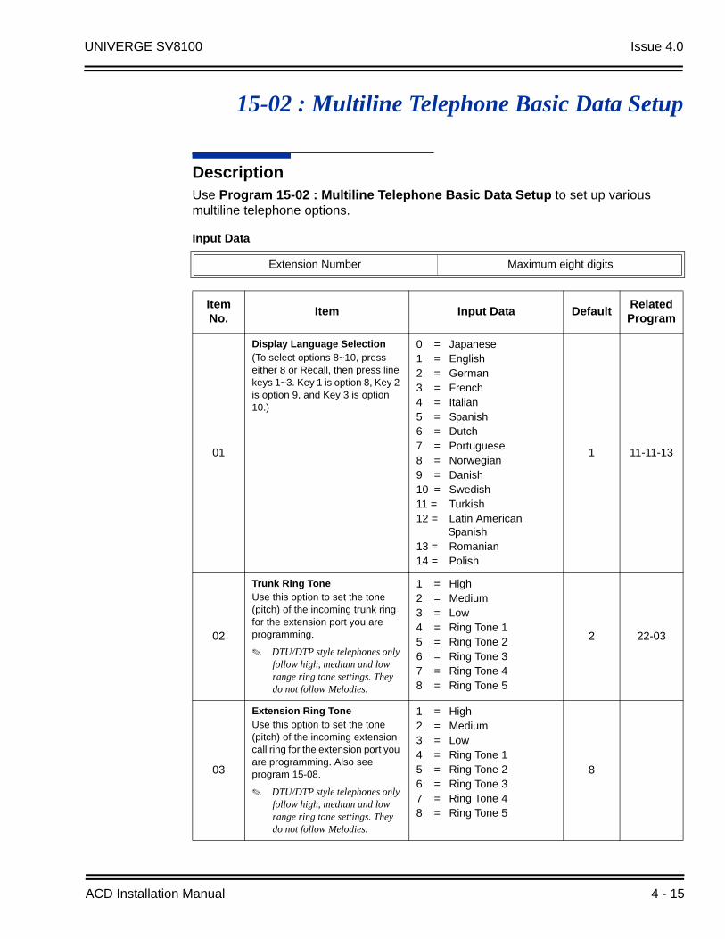
UNIVERGE SV8100 Issue 4.0
15-02 : Multiline Telephone Basic Data Setup
DescriptionUse Program 15-02 : Multiline Telephone Basic Data Setup to set up various multiline telephone options.
Input Data
Extension Number Maximum eight digits
Item No.
Item Input Data DefaultRelated Program
01
Display Language Selection(To select options 8~10, press either 8 or Recall, then press line keys 1~3. Key 1 is option 8, Key 2 is option 9, and Key 3 is option 10.)
0 = Japanese1 = English2 = German3 = French4 = Italian5 = Spanish6 = Dutch7 = Portuguese8 = Norwegian9 = Danish10 = Swedish11 = Turkish12 = Latin American
Spanish13 = Romanian14 = Polish
1 11-11-13
02
Trunk Ring ToneUse this option to set the tone (pitch) of the incoming trunk ring for the extension port you are programming.
DTU/DTP style telephones only follow high, medium and low range ring tone settings. They do not follow Melodies.
1 = High2 = Medium3 = Low4 = Ring Tone 15 = Ring Tone 26 = Ring Tone 37 = Ring Tone 48 = Ring Tone 5
2 22-03
03
Extension Ring Tone Use this option to set the tone (pitch) of the incoming extension call ring for the extension port you are programming. Also see program 15-08.
DTU/DTP style telephones only follow high, medium and low range ring tone settings. They do not follow Melodies.
1 = High2 = Medium3 = Low4 = Ring Tone 15 = Ring Tone 26 = Ring Tone 37 = Ring Tone 48 = Ring Tone 5
8
ACD Installation Manual 4 - 15
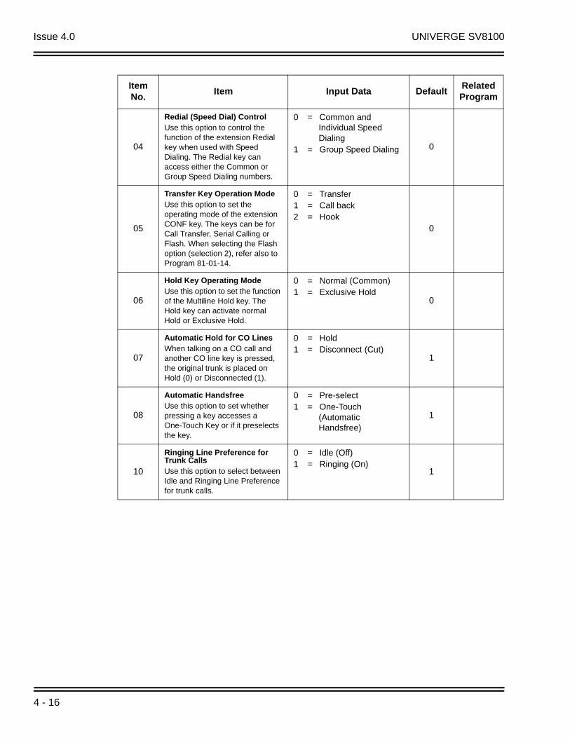
Issue 4.0 UNIVERGE SV8100
04
Redial (Speed Dial) ControlUse this option to control the function of the extension Redial key when used with Speed Dialing. The Redial key can access either the Common or Group Speed Dialing numbers.
0 = Common and Individual Speed Dialing
1 = Group Speed Dialing 0
05
Transfer Key Operation ModeUse this option to set the operating mode of the extension CONF key. The keys can be for Call Transfer, Serial Calling or Flash. When selecting the Flash option (selection 2), refer also to Program 81-01-14.
0 = Transfer1 = Call back2 = Hook
0
06
Hold Key Operating ModeUse this option to set the function of the Multiline Hold key. The Hold key can activate normal Hold or Exclusive Hold.
0 = Normal (Common)1 = Exclusive Hold
0
07
Automatic Hold for CO LinesWhen talking on a CO call and another CO line key is pressed, the original trunk is placed on Hold (0) or Disconnected (1).
0 = Hold1 = Disconnect (Cut)
1
08
Automatic HandsfreeUse this option to set whether pressing a key accesses a One-Touch Key or if it preselects the key.
0 = Pre-select1 = One-Touch
(Automatic Handsfree)
1
10
Ringing Line Preference for Trunk CallsUse this option to select between Idle and Ringing Line Preference for trunk calls.
0 = Idle (Off)1 = Ringing (On)
1
Item No.
Item Input Data DefaultRelated Program
4 - 16

UNIVERGE SV8100 Issue 4.0
11
Callback Automatic AnswerUse this option to enable or disable automatic answer of calls recalling to a station. For example, if a Transfer Recall or Hold Recall is ringing back to a station, the following happens:
If PRG 15-02-11 is enabled, the station will automatically answer the recall when it goes off-hook.
If PRG 15-02-11 is disabled, a station will not automatically answer the recall when it goes off-hook. The user must first press the line appearance of the recalling call or press the answer key.
0 = Off1 = On
1
12
Off-Hook RingingUse this option to set the telephone Off-Hook signaling. Off-hook signaling occurs when a telephone user receives a second call while busy on a handset call. To enable/disable Off-Hook Signaling for an extension Class of Service, use Program 20-13-06
0 = Muted Off-Hook Ringing
1 = No Off-Hook Ringing2 = Not Used3 = Beep in Speaker (SP)4 = Beep in Handset (HS)5 = Speaker and Handset
Beep
5
13
Redial List ModeSelect whether the Redial List feature should store internal and external numbers (0), or only external numbers (1).
0 = ICM/Trunk (Extension/Trunk Mode)
1 = Trunk Mode
1
15Storage of Caller-ID for answered call
0 = Disable (Off)1 = Enable (On)
1
16
Handsfree OperationEnable or disable an extension ability to use the speakerphone on outside calls. When disabled, users can hear the conversation, but cannot respond handsfree.
0 = Disable (Off)1 = Enable (On)
1
18Power-Saving Mode 0 = Normal mode
1 = Power-Saving Mode (Eco-Mode)
1 20-02-10
Item No.
Item Input Data DefaultRelated Program
ACD Installation Manual 4 - 17

Issue 4.0 UNIVERGE SV8100
19
CTA Data Communication ModeSelect 0 if the dip switch settings on the CTA Adapter are set to PC connection (1=on, 2~8=off) or select 1 if the DIP switches are set to printer connection (1~2=on, 3~8=off).
0 = CTI Mode1 = Non Procedural Mode
(Non-SCS)0 15-02-20
20Baud Rate for CTA PortSelect the baud rate to be used by the CTA Adapter.
0 = 48001 = 96002 = 19200
2 15-02-19
21
Virtual Extension Access Mode (when idle Virtual Extension key pressed)Determine whether a Virtual Extension/Call Arrival Key(CAR) should function as a DSS key, a Virtual Extension, or a CAR key. When DSS (0) is selected, the key functions as a DSS key to the extension and for incoming calls to that extension. When Outgoing (1) is selected, the key functions as a virtual extension and can be used for incoming and outgoing calls. When Ignore (2) is selected, the key functions as a CAR key and can receive incoming calls only.
0 = DSS 1 = Outgoing (OTG)2 = Ignore
2
22
Multiple Incoming From Intercom and TrunkIf enabled, this affects how a Hotline key lights, based on the setting in Program 22-01-01. If 22-01-01 is set to 1 for trunk priority, the Hotline key lights solid when a trunk call rings in. If 22-01-01 is set to 0 for intercom priority, the Hotline key does not light for incoming trunk calls, but lights solid for intercom calls.
If 15-02-22 is disabled, Hotline keys light solid for any incoming calls regardless of the setting in Program 22-01-01.
0 = Disable1 = Enable
1 22-01-01
Item No.
Item Input Data DefaultRelated Program
4 - 18

UNIVERGE SV8100 Issue 4.0
23
Speed Dial Preview ModeThis option defines how a speed dial key functions when pressed. If set to Preview (0), the speed dial number can be previewed before dialing. If set to Outgoing Immediate (1), the number is dialed immediately.
0 = Preview1 = Outgoing Immediately
0
24
Conference Key ModeThis option allows an extension CONF key to be programmed for Conference or for Transfer. When set for Transfer (1), the user places a call on hold, dials the extension to which it should be transferred, then presses the CONF key. The call is then transferred. When set for Conference (0), with an active call, the user presses the CONF key, places a second call, then presses the CONF key twice. All the calls are then connected.
0 = Conference1 = Transfer
0
26
MSG Key Operation ModeDetermine whether an extension MSG key should function as a Message key or Voice Mail key. If set as a Message key, users can press the key to call the voice mail only when they have new messages.
0 = Message Key1 = Voice Mail Key
0
27
Handset VolumeDetermine how an extension handset volume is set after it is adjusted during a call.
When 1 is assigned in this program and a user sets the volume to maximum, the volume is reset to a level to meet FCC standards when the user hangs up.
0 = Back to Default (Back)
1 = Stay at previous level (Stay)
1
28
Message Waiting Lamp ColorDetermine whether an extension Message Waiting Lamp lights Green (0) or Red (1) when a message is received.
0 = Green1 = Red
1
15-02-3515-02-3615-02-3715-02-38
29
PB Back Tone LevelThis program allows adjustment of the PB Back Tone Level when you are calling an ISDN Line.
1~63 (-15.5dB ~ +15.5dB)32
(0dB)
Item No.
Item Input Data DefaultRelated Program
ACD Installation Manual 4 - 19
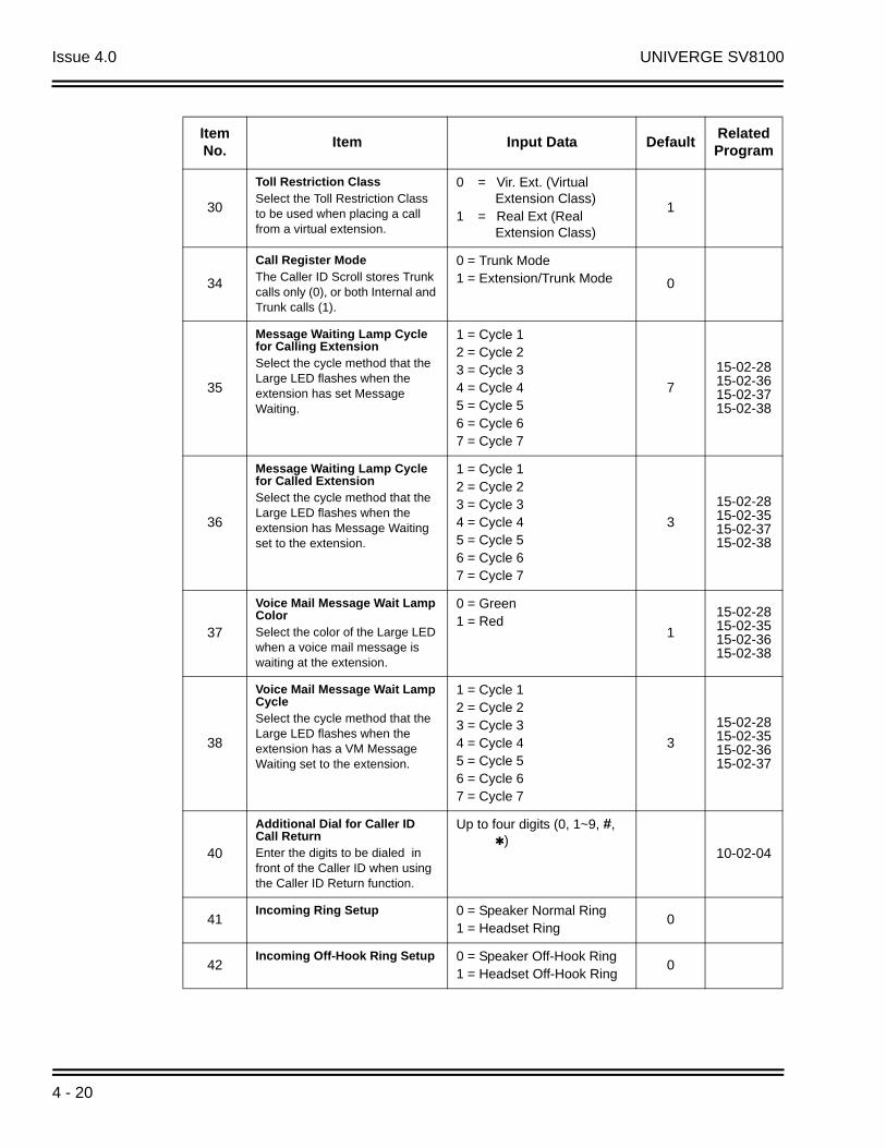
Issue 4.0 UNIVERGE SV8100
30
Toll Restriction ClassSelect the Toll Restriction Class to be used when placing a call from a virtual extension.
0 = Vir. Ext. (Virtual Extension Class)
1 = Real Ext (Real Extension Class)
1
34
Call Register ModeThe Caller ID Scroll stores Trunk calls only (0), or both Internal and Trunk calls (1).
0 = Trunk Mode1 = Extension/Trunk Mode 0
35
Message Waiting Lamp Cycle for Calling ExtensionSelect the cycle method that the Large LED flashes when the extension has set Message Waiting.
1 = Cycle 12 = Cycle 23 = Cycle 34 = Cycle 45 = Cycle 56 = Cycle 67 = Cycle 7
7
15-02-2815-02-3615-02-3715-02-38
36
Message Waiting Lamp Cycle for Called ExtensionSelect the cycle method that the Large LED flashes when the extension has Message Waiting set to the extension.
1 = Cycle 12 = Cycle 23 = Cycle 34 = Cycle 45 = Cycle 56 = Cycle 67 = Cycle 7
3
15-02-2815-02-3515-02-3715-02-38
37
Voice Mail Message Wait Lamp ColorSelect the color of the Large LED when a voice mail message is waiting at the extension.
0 = Green1 = Red
1
15-02-2815-02-3515-02-3615-02-38
38
Voice Mail Message Wait Lamp CycleSelect the cycle method that the Large LED flashes when the extension has a VM Message Waiting set to the extension.
1 = Cycle 12 = Cycle 23 = Cycle 34 = Cycle 45 = Cycle 56 = Cycle 67 = Cycle 7
3
15-02-2815-02-3515-02-3615-02-37
40
Additional Dial for Caller ID Call ReturnEnter the digits to be dialed in front of the Caller ID when using the Caller ID Return function.
Up to four digits (0, 1~9, #, )
10-02-04
41Incoming Ring Setup 0 = Speaker Normal Ring
1 = Headset Ring0
42Incoming Off-Hook Ring Setup 0 = Speaker Off-Hook Ring
1 = Headset Off-Hook Ring0
Item No.
Item Input Data DefaultRelated Program
4 - 20
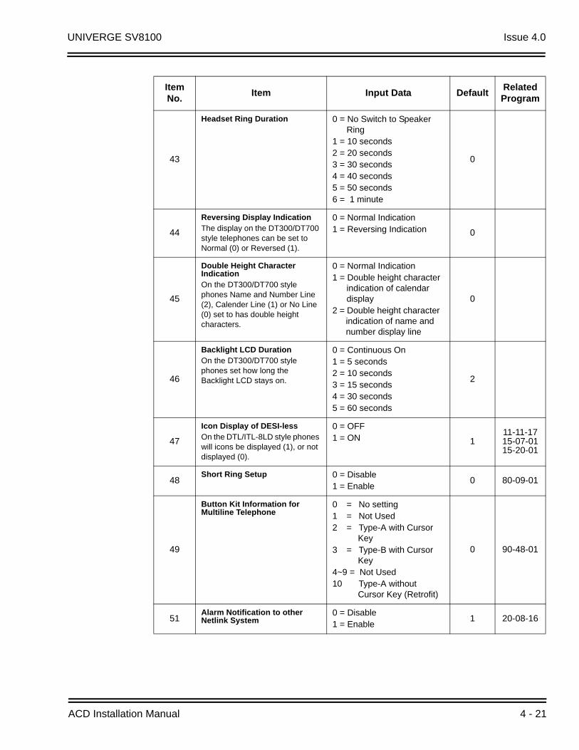
UNIVERGE SV8100 Issue 4.0
43
Headset Ring Duration 0 = No Switch to Speaker Ring
1 = 10 seconds2 = 20 seconds3 = 30 seconds4 = 40 seconds5 = 50 seconds6 = 1 minute
0
44
Reversing Display IndicationThe display on the DT300/DT700 style telephones can be set to Normal (0) or Reversed (1).
0 = Normal Indication1 = Reversing Indication 0
45
Double Height Character IndicationOn the DT300/DT700 style phones Name and Number Line (2), Calender Line (1) or No Line (0) set to has double height characters.
0 = Normal Indication1 = Double height character
indication of calendar display
2 = Double height character indication of name and number display line
0
46
Backlight LCD DurationOn the DT300/DT700 style phones set how long the Backlight LCD stays on.
0 = Continuous On1 = 5 seconds2 = 10 seconds3 = 15 seconds4 = 30 seconds5 = 60 seconds
2
47
Icon Display of DESI-lessOn the DTL/ITL-8LD style phones will icons be displayed (1), or not displayed (0).
0 = OFF1 = ON 1
11-11-1715-07-0115-20-01
48Short Ring Setup 0 = Disable
1 = Enable0 80-09-01
49
Button Kit Information for Multiline Telephone
0 = No setting1 = Not Used2 = Type-A with Cursor
Key3 = Type-B with Cursor
Key4~9 = Not Used10 Type-A without
Cursor Key (Retrofit)
0 90-48-01
51Alarm Notification to other Netlink System
0 = Disable1 = Enable
1 20-08-16
Item No.
Item Input Data DefaultRelated Program
ACD Installation Manual 4 - 21

Issue 4.0 UNIVERGE SV8100
52
Voice Mail Message Waiting Lamp Setup
0 = Light the VM function key only.
1 = Light the Message Waiting lamp only.
2 = Light the MW lamp and VM key.
0 15-07-01
53Aspire Model –C Phone Operation Mode
0 = Original Operation Mode1 = CTI Special Operation
Mode0
54Menu Operation Mode 0 = Automatic Close
1 = Manual Close0
57Caller Log on Busy 0 = Off
1 = On1 15-02-34
58Display Mode of Incoming Trunk
0 = Caller ID1 = Memo Information 0
13-04-0813-04-0913-04-10
69
Microphone Operation on Handsfree
0 = No change for MIC status
1 = Start from MIC enabled2 = Start from MIC muted
0
70MIC Key Operation 0 = Enabled
1 = Disabled0
71Disable Softkey 0 = Off
1 = On0
Table 4-1 Lamp Cycle On/Off Timing Pattern
Programs 15-02-35, 36, and 38
Input Cycle
1 Cycle 1 500ms – ON / 500ms – OFF
2 Cycle 2 250ms – ON / 250ms – OFF
3 Cycle 3 125ms – ON / 125ms – OFF
4 Cycle 4 125ms – ON / 125ms – OFF / 125ms – ON / 625ms – OFF
5 Cycle 5 875ms – ON / 125ms – OFF
6 Cycle 6 625ms – ON / 125ms – OFF / 125ms – ON / 125ms – OFF
7 Cycle 7 1000ms – ON
Item No.
Item Input Data DefaultRelated Program
4 - 22

UNIVERGE SV8100 Issue 4.0
ConditionsNone
Feature Cross Reference
Refer to the Input Data chart.
Telephone Programming Instructions
To enter data for Program 15-02 (Multiline Telephone Basic Data Setup):
1. Enter the programming mode.
2. 15 02
1. Enter the number of the item you want to program.
Table 4-2 Program 15 : 02 – Incoming Signal Frequency Patterns
Incoming Signal Frequency Pattern
TypeFrequency
1Frequency
2Modulation
External Incoming Signal Frequency (Pattern 1)
HighMiddleLow
1100660520
1400760660
16Hz16Hz16Hz
External Incoming Signal Frequency (Pattern 2)
HighMiddleLow
1100Hz660Hz520Hz
1400Hz760Hz660Hz
8Hz8Hz8Hz
External Incoming Signal Frequency (Pattern 3)
HighMiddleLow
2000Hz1400Hz1100Hz
760Hz660Hz540Hz
16Hz16Hz16Hz
External Incoming Signal Frequency (Pattern 4)
HighMiddleLow
2000Hz1400Hz1100Hz
760Hz660Hz540Hz
8Hz8Hz8Hz
Internal Incoming Signal Frequency
HighMiddleLow
1100Hz660Hz520Hz
1400Hz760Hz660Hz
8Hz8Hz8Hz
15-02-01 TEL301200
Language 1:English
back select
15-02-nn TELnnn
nnnnn
ACD Installation Manual 4 - 23

Issue 4.0 UNIVERGE SV8100
2. To select the telephone number to be programmed, press the FLASH or the volume or keys.
3. Enter data for the item you selected + Hold.
4. Enter data for the next item in the program.
- OR -
Press MSG once to enter a new item number.
- OR -
Press MSG until you exit that series programming section.
4 - 24

UNIVERGE SV8100 Issue 4.0
15-07 : Programmable Function Keys
DescriptionUse Program 15-07 : Programmable Function Keys to assign functions to a multiline terminal line keys.
For certain functions, you can append data to the key basic function. For example, the function 26 appended by data 1 makes a Group Call Pickup key for Pickup Group 1. You can also program Function Keys using Service Codes.
To clear any previously programmed key, press 000 to erase any displayed code.
Default Settings
DefaultProgrammable keys 1~8 are Trunk Line keys (key 1 = Trunk Line 1, key 2 = Trunk Line 2, etc.). All other programmable keys are undefined.
Input Data
Extension Number Maximum eight digits
Line Key Function Number Additional Data
LK01 01 (Trunk Line Key) 1
: : :
LK08 01 (Trunk Line Key) 8
LK09 0 (No Setting) 0
: : :
LK48 0 (No Setting) 0
Item No.
Line Key Number
Function Number Additional Data
01 1~48
0~99(Normal Function Code) (Service Code 751 by default)* 00-* 99(Appearance Function Code) (Service Code 752 by default)
Refer to Function Number List.
ACD Installation Manual 4 - 25
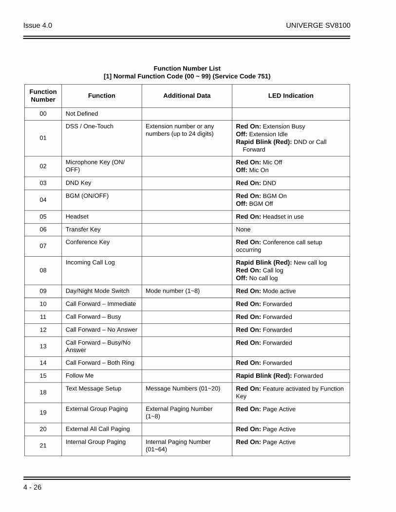
Issue 4.0 UNIVERGE SV8100
Function Number List[1] Normal Function Code (00 ~ 99) (Service Code 751)
Function Number
Function Additional Data LED Indication
00 Not Defined
01
DSS / One-Touch Extension number or any numbers (up to 24 digits)
Red On: Extension BusyOff: Extension IdleRapid Blink (Red): DND or Call Forward
02Microphone Key (ON/OFF)
Red On: Mic OffOff: Mic On
03 DND Key Red On: DND
04BGM (ON/OFF) Red On: BGM On
Off: BGM Off
05 Headset Red On: Headset in use
06 Transfer Key None
07Conference Key Red On: Conference call setup
occurring
08Incoming Call Log Rapid Blink (Red): New call log
Red On: Call logOff: No call log
09 Day/Night Mode Switch Mode number (1~8) Red On: Mode active
10 Call Forward – Immediate Red On: Forwarded
11 Call Forward – Busy Red On: Forwarded
12 Call Forward – No Answer Red On: Forwarded
13Call Forward – Busy/No Answer
Red On: Forwarded
14 Call Forward – Both Ring Red On: Forwarded
15 Follow Me Rapid Blink (Red): Forwarded
18Text Message Setup Message Numbers (01~20) Red On: Feature activated by Function
Key
19External Group Paging External Paging Number
(1~8)Red On: Page Active
20 External All Call Paging Red On: Page Active
21Internal Group Paging Internal Paging Number
(01~64)Red On: Page Active
4 - 26
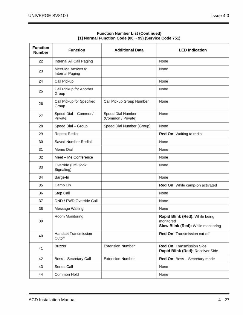
UNIVERGE SV8100 Issue 4.0
22 Internal All Call Paging None
23Meet-Me Answer to Internal Paging
None
24 Call Pickup None
25Call Pickup for Another Group
None
26Call Pickup for Specified Group
Call Pickup Group Number None
27Speed Dial – Common/Private
Speed Dial Number (Common / Private)
None
28 Speed Dial – Group Speed Dial Number (Group) None
29 Repeat Redial Red On: Waiting to redial
30 Saved Number Redial None
31 Memo Dial None
32 Meet – Me Conference None
33Override (Off-Hook Signaling)
None
34 Barge-In None
35 Camp On Red On: While camp-on activated
36 Step Call None
37 DND / FWD Override Call None
38 Message Waiting None
39Room Monitoring Rapid Blink (Red): While being
monitoredSlow Blink (Red): While monitoring
40Handset Transmission Cutoff
Red On: Transmission cut-off
41Buzzer Extension Number Red On: Transmission Side
Rapid Blink (Red): Receiver Side
42 Boss – Secretary Call Extension Number Red On: Boss – Secretary mode
43 Series Call None
44 Common Hold None
Function Number List (Continued)[1] Normal Function Code (00 ~ 99) (Service Code 751)
Function Number
Function Additional Data LED Indication
ACD Installation Manual 4 - 27

Issue 4.0 UNIVERGE SV8100
45 Exclusive None
46Department Group Log Out
Red On: Logged Out
47
Reverse Voice Over Extension Number Red On: extension busyOff: extension idleRapid Blink (Red): DND or Call ForwardGreen: Reverse Voice Over to extension in progress
48 Voice Over Slow Blink (Red): Voice Over – Active
49Call Redirect Extension Number or Voice
Mail NumberNone
50Account Code Red On: While account code being
entered
51 General Purpose Relay Relay No (0, 1~8) Red On: Relay On
52Automatic Answer with Delay Message Setup
Incoming Ring Group (001~100)
Red On: Under setting
53Automatic Answer with Delay Message Start
Red On: Active
54External Call Forward by Door Box
Red On: Active
55 Extension Name Change None
56General Purpose LED Operation
Blink (Red): Active
57General Purpose LED Indication
Blink (Red): Active
58Automatic Transfer at Department Group Call
Extension Group Number( 01~64)
Blink (Red): Active
59Delayed Transfer at Department Group Call
Extension Group Number (01~64)
Blink (Red): Active
60DND at Department Group Call
Extension Group Number (01~64)
Blink (Red): Active
61 --- Not Used ---
63Outgoing Call Without Caller ID (ISDN)
Red On: Active
Function Number List (Continued)[1] Normal Function Code (00 ~ 99) (Service Code 751)
Function Number
Function Additional Data LED Indication
4 - 28
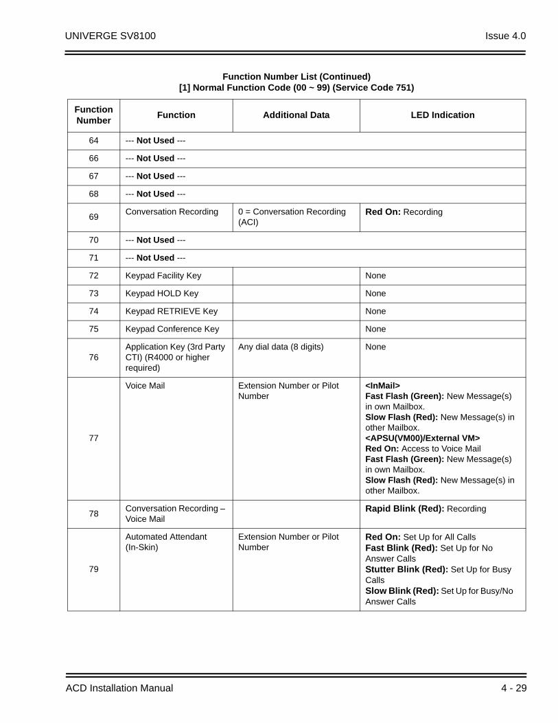
UNIVERGE SV8100 Issue 4.0
64 --- Not Used ---
66 --- Not Used ---
67 --- Not Used ---
68 --- Not Used ---
69Conversation Recording 0 = Conversation Recording
(ACI)Red On: Recording
70 --- Not Used ---
71 --- Not Used ---
72 Keypad Facility Key None
73 Keypad HOLD Key None
74 Keypad RETRIEVE Key None
75 Keypad Conference Key None
76Application Key (3rd Party CTI) (R4000 or higher required)
Any dial data (8 digits) None
77
Voice Mail Extension Number or Pilot Number
<InMail>Fast Flash (Green): New Message(s)in own Mailbox.Slow Flash (Red): New Message(s) inother Mailbox.<APSU(VM00)/External VM>Red On: Access to Voice MailFast Flash (Green): New Message(s)in own Mailbox.Slow Flash (Red): New Message(s) inother Mailbox.
78Conversation Recording – Voice Mail
Rapid Blink (Red): Recording
79
Automated Attendant (In-Skin)
Extension Number or Pilot Number
Red On: Set Up for All CallsFast Blink (Red): Set Up for No Answer CallsStutter Blink (Red): Set Up for Busy CallsSlow Blink (Red): Set Up for Busy/No Answer Calls
Function Number List (Continued)[1] Normal Function Code (00 ~ 99) (Service Code 751)
Function Number
Function Additional Data LED Indication
ACD Installation Manual 4 - 29
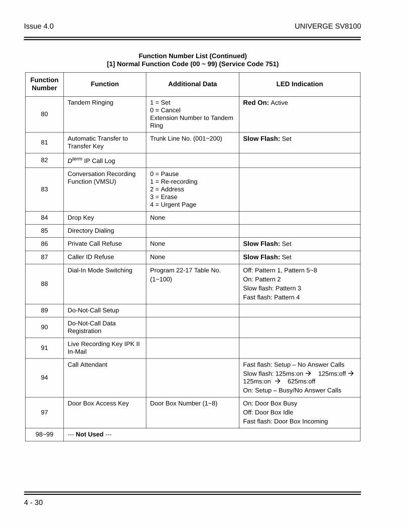
Issue 4.0 UNIVERGE SV8100
80
Tandem Ringing 1 = Set 0 = CancelExtension Number to Tandem Ring
Red On: Active
81Automatic Transfer to Transfer Key
Trunk Line No. (001~200) Slow Flash: Set
82 Dterm IP Call Log
83
Conversation Recording Function (VMSU)
0 = Pause1 = Re-recording2 = Address3 = Erase4 = Urgent Page
84 Drop Key None
85 Directory Dialing
86 Private Call Refuse None Slow Flash: Set
87 Caller ID Refuse None Slow Flash: Set
88
Dial-In Mode Switching Program 22-17 Table No.
(1~100)
Off: Pattern 1, Pattern 5~8
On: Pattern 2
Slow flash: Pattern 3
Fast flash: Pattern 4
89 Do-Not-Call Setup
90Do-Not-Call Data Registration
91Live Recording Key IPK II In-Mail
94
Call Attendant Fast flash: Setup – No Answer Calls
Slow flash: 125ms:on 125ms:off 125ms:on 625ms:off
On: Setup – Busy/No Answer Calls
97
Door Box Access Key Door Box Number (1~8) On: Door Box Busy
Off: Door Box Idle
Fast flash: Door Box Incoming
98~99 --- Not Used ---
Function Number List (Continued)[1] Normal Function Code (00 ~ 99) (Service Code 751)
Function Number
Function Additional Data LED Indication
4 - 30
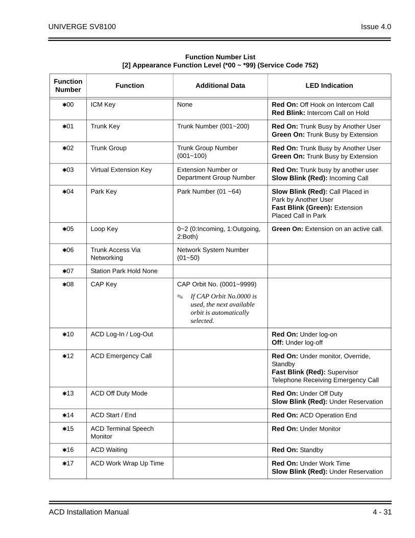
UNIVERGE SV8100 Issue 4.0
Function Number List[2] Appearance Function Level (*00 ~ *99) (Service Code 752)
Function Number
Function Additional Data LED Indication
00 ICM Key None Red On: Off Hook on Intercom CallRed Blink: Intercom Call on Hold
01 Trunk Key Trunk Number (001~200) Red On: Trunk Busy by Another UserGreen On: Trunk Busy by Extension
02 Trunk Group Trunk Group Number(001~100)
Red On: Trunk Busy by Another UserGreen On: Trunk Busy by Extension
03 Virtual Extension Key Extension Number or Department Group Number
Red On: Trunk busy by another userSlow Blink (Red): Incoming Call
04 Park Key Park Number (01 ~64) Slow Blink (Red): Call Placed in Park by Another UserFast Blink (Green): Extension Placed Call in Park
05 Loop Key 0~2 (0:Incoming, 1:Outgoing, 2:Both)
Green On: Extension on an active call.
06 Trunk Access Via Networking
Network System Number (01~50)
07 Station Park Hold None
08 CAP Key CAP Orbit No. (0001~9999)
If CAP Orbit No.0000 is used, the next available orbit is automatically selected.
10 ACD Log-In / Log-Out Red On: Under log-onOff: Under log-off
12 ACD Emergency Call Red On: Under monitor, Override, StandbyFast Blink (Red): Supervisor Telephone Receiving Emergency Call
13 ACD Off Duty Mode Red On: Under Off DutySlow Blink (Red): Under Reservation
14 ACD Start / End Red On: ACD Operation End
15 ACD Terminal Speech Monitor
Red On: Under Monitor
16 ACD Waiting Red On: Standby
17 ACD Work Wrap Up Time Red On: Under Work TimeSlow Blink (Red): Under Reservation
ACD Installation Manual 4 - 31

Issue 4.0 UNIVERGE SV8100
18 ACD Overflow Control ACD Group Number Red On: EnableSlow Blink (Red): Disable
19 ACD Queue Status Display Check
32 Warning Message On(Red): Play Warning MessageOff: Stop Warning Message
33 Sensor Mode Related Program 20-50-01 On(Red): Security Sensor OnOff: Security Sensor Off
34 ACD Caller ID Marking Setup
Function Number List (Continued)[2] Appearance Function Level (*00 ~ *99) (Service Code 752)
4 - 32

UNIVERGE SV8100 Issue 4.0
LED Indication Reference:
ON = LED pattern 7 (On).OFF = LED pattern 0 (Off).Rapid Blink = LED pattern 3 (RW).Slow Blink (General Function Level) = LED pattern 5 (IL).Slow Blink (Appearance Function Level) = LED pattern 1 (FL).Fast Blink = LED pattern 3 (RW).Stutter Blink = LED pattern 4 (IR).
LED Pattern 0 : [OFF]
On
Off
LED Pattern 1 : [FL: On(500ms)/Off(500ms)]
On
Off
LED Pattern 2 : [WK: On(250ms)/Off(250ms)]
On
Off
LED Pattern 3 : [RW: On(125ms)/Off(125ms)]
On
Off
LED Pattern 4 : [IR: On(125ms)/Off(125ms)/On(125ms)/Off(625ms)]
On
Off
LED Pattern 5 : [IL: On(875ms)/Off(125ms)]
On
Off
LED Pattern 6 : [IW: On(625ms)/Off(125ms)/On(125ms)/Off(125ms)]
On
Off
LED Pattern 7 : [ON]
On
Off
ACD Installation Manual 4 - 33

Issue 4.0 UNIVERGE SV8100
Conditions
When a key is programmed using service code 752, that key cannot be programmed with a function using the 751 code until the key is undefined (000). For example, with a Park Key programmed by dialing 752 + 04 must be undefined by dialing 752 + 000 before it can be programmed as a Voice Over key by dialing 751 + 48.
When assigning a CAP key, 08, an orbit number must be used. If orbit 000 is used, it automatically assigns the next available orbit.
Feature Cross Reference
Refer to Function Number List.
Telephone Programming Instructions
To enter data for Program 15-07 (Programmable Function Keys):
1. Enter the programming mode.
2. 15 07
3. Enter the number of the item you want to program.
4. To select the telephone number to be programmed, press the FLASH or the volume or keys.
5. Enter data for the item you selected + Hold.
6. Enter data for the next item in the program.
- OR -
Press MSG once to enter a new item number.
- OR -
Press MSG until you exit that series programming section.
15-07-01 TEL301200
KY01 = *01
back select
15-07-nn TELnnn
nnnnn
4 - 34
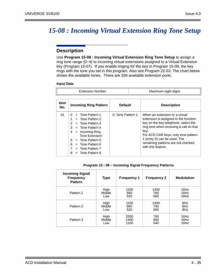
UNIVERGE SV8100 Issue 4.0
15-08 : Incoming Virtual Extension Ring Tone Setup
DescriptionUse Program 15-08 : Incoming Virtual Extension Ring Tone Setup to assign a ring tone range (0~4) to incoming virtual extensions assigned to a Virtual Extension key (Program 15-07). If you enable ringing for the key in Program 15-09, the key rings with the tone you set in this program. Also see Program 22-03. The chart below shows the available tones. There are 256 available extension ports.
Input Data
Extension Number Maximum eight digits
Item No.
Incoming Ring Pattern Default Description
01 0 = Tone Pattern 11 = Tone Pattern 22 = Tone Pattern 33 = Tone Pattern 44 = Incoming Ring
Tone Extension5 = Tone Pattern 56 = Tone Pattern 67 = Tone Pattern 78 = Tone Pattern 8
0: Tone Pattern 1 When an extension or a virtual extension is assigned to the function key on the key telephone, select the ring tone when receiving a call on that key.For ACD CAR keys, only tone pattern 1 (entry 0) can be used. The remaining patterns are not checked with this feature.
Program 15 : 08 – Incoming Signal Frequency Patterns
Incoming Signal Frequency
PatternType Frequency 1 Frequency 2 Modulation
Pattern 1High
MiddleLow
1100660520
1400760660
16Hz16Hz16Hz
Pattern 2High
MiddleLow
1100660520
1400760660
8Hz8Hz8Hz
Pattern 3High
MiddleLow
200014001100
760660540
16Hz16Hz16Hz
ACD Installation Manual 4 - 35
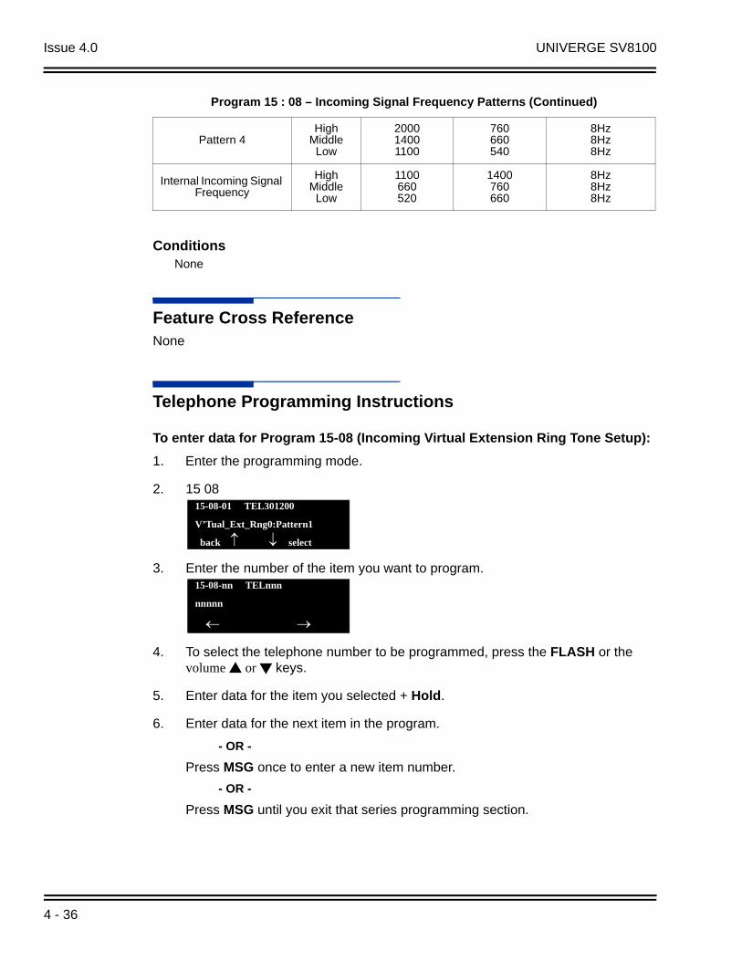
Issue 4.0 UNIVERGE SV8100
ConditionsNone
Feature Cross ReferenceNone
Telephone Programming Instructions
To enter data for Program 15-08 (Incoming Virtual Extension Ring Tone Setup):
1. Enter the programming mode.
2. 15 08
3. Enter the number of the item you want to program.
4. To select the telephone number to be programmed, press the FLASH or the volume or keys.
5. Enter data for the item you selected + Hold.
6. Enter data for the next item in the program.
- OR -
Press MSG once to enter a new item number.
- OR -
Press MSG until you exit that series programming section.
Pattern 4High
MiddleLow
200014001100
760660540
8Hz8Hz8Hz
Internal Incoming Signal Frequency
HighMiddle
Low
1100660520
1400760660
8Hz8Hz8Hz
15-08-01 TEL301200
V’Tual_Ext_Rng0:Pattern1
back select
15-08-nn TELnnn
nnnnn
Program 15 : 08 – Incoming Signal Frequency Patterns (Continued)
4 - 36
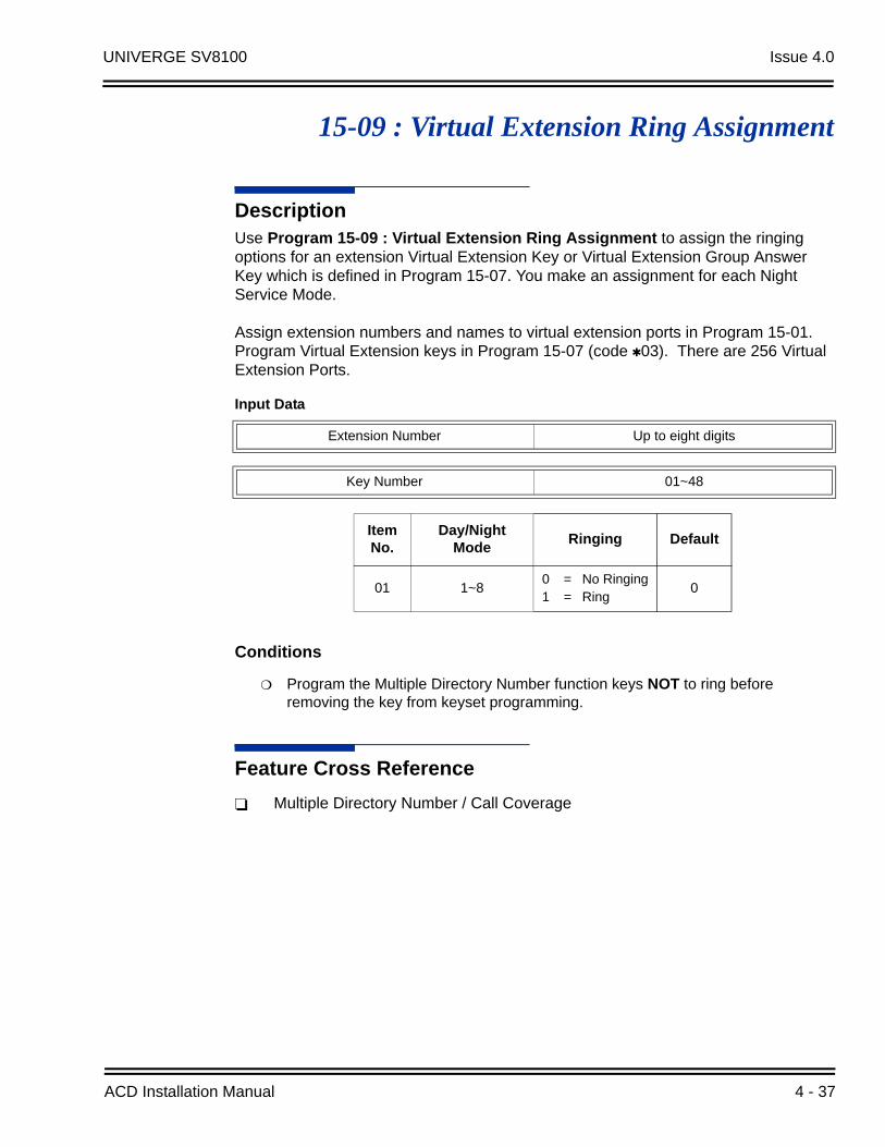
UNIVERGE SV8100 Issue 4.0
15-09 : Virtual Extension Ring Assignment
DescriptionUse Program 15-09 : Virtual Extension Ring Assignment to assign the ringing options for an extension Virtual Extension Key or Virtual Extension Group Answer Key which is defined in Program 15-07. You make an assignment for each Night Service Mode.
Assign extension numbers and names to virtual extension ports in Program 15-01. Program Virtual Extension keys in Program 15-07 (code 03). There are 256 Virtual Extension Ports.
Conditions
Program the Multiple Directory Number function keys NOT to ring before removing the key from keyset programming.
Feature Cross Reference
Multiple Directory Number / Call Coverage
Input Data
Extension Number Up to eight digits
Key Number 01~48
Item No.
Day/Night Mode
Ringing Default
01 1~80 = No Ringing1 = Ring
0
ACD Installation Manual 4 - 37
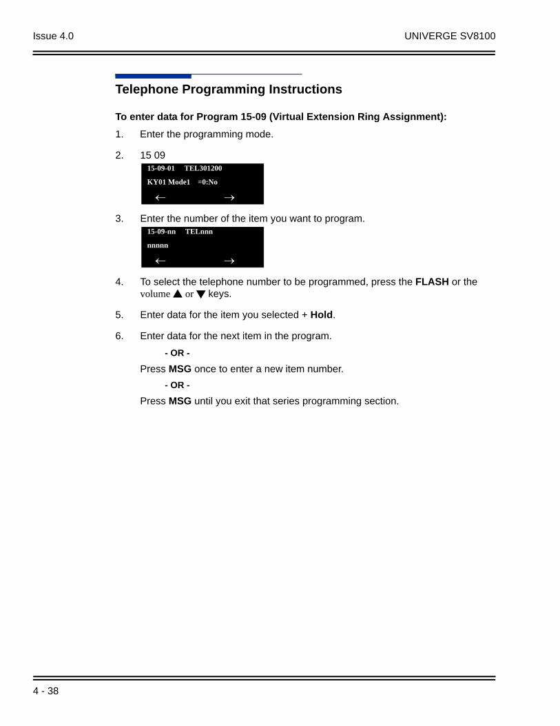
Issue 4.0 UNIVERGE SV8100
Telephone Programming Instructions
To enter data for Program 15-09 (Virtual Extension Ring Assignment):
1. Enter the programming mode.
2. 15 09
3. Enter the number of the item you want to program.
4. To select the telephone number to be programmed, press the FLASH or the volume or keys.
5. Enter data for the item you selected + Hold.
6. Enter data for the next item in the program.
- OR -
Press MSG once to enter a new item number.
- OR -
Press MSG until you exit that series programming section.
15-09-01 TEL301200
KY01 Mode1 =0:No
15-09-nn TELnnn
nnnnn
4 - 38

UNIVERGE SV8100 Issue 4.0
15-10 : Incoming Virtual Extension Ring Tone Order Setup
DescriptionUse Program 15-10 : Incoming Virtual Extension Ring Tone Order Setup to set the priority (1~4) for the Virtual Extension Ring Tones set in Program 15-08. When Virtual Extension calls ring an extension simultaneously, the tone with the highest order number (e.g., 1) rings. The other keys only flash. There are 256 Virtual Extension ports.
Default
By default, Virtual Extension ring tones have the following order:
ConditionsNone
Input Data
Extension Number Up to eight digits
Item No.
Order Data DescriptionRelated Program
01 1~4
0 = Tone Pattern 11 = Tone Pattern 22 = Tone Pattern 33 = Tone Pattern 44 = Incoming Extension
Ring Tone5 = Tone Pattern 56 = Tone Pattern 67 = Tone Pattern 78 = Tone Pattern 8
When two or more virtual extensions are set on a function key on the keyset, and the tone pattern by which the sound of each extension differs, the priority of ring sound is set up.
15-08
OrderRing Tone
(Set in Program 15-08)
1 0 (Tone Pattern 1)
2 1 (Tone Pattern 2)
3 2 (Tone Pattern 3)
4 3 (Tone Pattern 4)
ACD Installation Manual 4 - 39
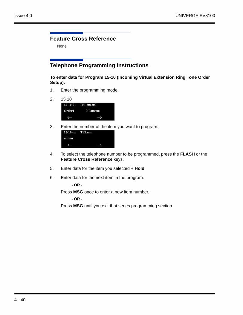
Issue 4.0 UNIVERGE SV8100
Feature Cross ReferenceNone
Telephone Programming Instructions
To enter data for Program 15-10 (Incoming Virtual Extension Ring Tone Order Setup):
1. Enter the programming mode.
2. 15 10
3. Enter the number of the item you want to program.
4. To select the telephone number to be programmed, press the FLASH or the Feature Cross Reference keys.
5. Enter data for the item you selected + Hold.
6. Enter data for the next item in the program.
- OR -
Press MSG once to enter a new item number.
- OR -
Press MSG until you exit that series programming section.
15-10-01 TEL301200
Order1 0:Pattern1
15-10-nn TELnnn
nnnnn
4 - 40

UNIVERGE SV8100 Issue 4.0
15-11 : Virtual Extension Delayed Ring Assignment
DescriptionUse Program 15-11 : Virtual Extension Delayed Ring Assignment to assign the delayed ringing options for an extension Virtual Extension or Virtual Extension Group Answer keys (defined in Program 15-09). You make an assignment for each Night Service Mode. There are 256 Virtual Extension Ports.
Assign extension numbers (Program 11-04) and names (Program 15-01) to virtual extension ports. Program Multiple Directory Number (virtual extension) keys in Program 15-07 (code 03).
Conditions
Program the Virtual Extension keys NOT to ring before removing the key from keyset programming.
PRG 15-09-01 has to be assigned to Ring Immediately before assigning the CAR/VE key to Delay Ring.
Feature Cross ReferenceNone
Input Data
Extension Number Maximum eight digits
Key Number 01~48
Item No.
Day/Night Mode
Ringing DefaultRelated Program
01 1~8 0 = Immediate Ring
1 = Delayed Ring
0 20-04-0315-09-01
ACD Installation Manual 4 - 41

Issue 4.0 UNIVERGE SV8100
Telephone Programming Instructions
To enter data for Program 15-11 (Virtual Extension Delayed Ring Assignment):
1. Enter the programming mode.
2. 15 11
3. Enter the number of the item you want to program.
4. To Select the telephone number to be programmed, press the FLASH or the volume or keys.
5. Enter data for the item you selected + Hold.
6. Enter data for the next item in the program.
- OR -
Press MSG once to enter a new item number.
- OR -
Press MSG until you exit that series programming section.
15-11-01 TEL301200
KY01 Mode1 =0:No
back select
15-11-nn TELnnn
nnnnn
4 - 42
UNIVERGE SV8100 Issue 4.0
20-02 : System Options for Multiline Telephones
DescriptionUse Program 20-02 : System Options for Multiline Telephones to set various system options for multiline telephones.
Input Data
Item No.
Item Input Data DefaultRelated
Programming
01 Trunk Group Key Operation Mode
0 = Display1 = No Display
1
Mode 0 = Display 1 = No Dis-play
Incom-ing:
300 IPM Red blink
Talking: Green Light-ing (on Talk-
ing TEL)
LED Off
Holding: 60 IPM Green blink (on holding
TEL)
LED Off
02
Trunk Group Access Key Operating ModeUse this option to set the operating mode of the extension trunk group keys. The keys are for incoming access, outgoing access, or both.
0 = Outgoing/Incoming1 = Outgoing2 = Incoming 0
04
Retrieve the Line After TransferEnable (1) or Disable (0) an extension ability to answer a call after it has been transferred, but before it is answered.
0 = Not Holding (No Keep)1 = Holding (Keep)
1
05
Headset Busy ModeSet the conditions under which a headset extension is busy to incoming callers.
0 = No (Disable)1 = Yes (Enable) 0 20-09-07
06
Preselection TimeWhen a multiline terminal user preselects a line key, the system remembers the preselection for this time.
0~64800 seconds
5
ACD Installation Manual 4 - 43
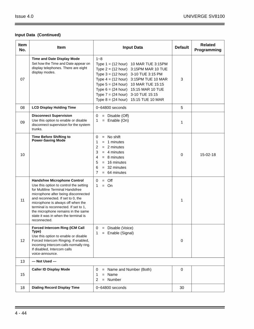
Issue 4.0 UNIVERGE SV8100
07
Time and Date Display ModeSet how the Time and Date appear on display telephones. There are eight display modes.
1~8Type 1 = (12 hour) 10 MAR TUE 3:15PMType 2 = (12 hour) 3:15PM MAR 10 TUEType 3 = (12 hour) 3-10 TUE 3:15 PMType 4 = (12 hour) 3:15PM TUE 10 MARType 5 = (24 hour) 10 MAR TUE 15:15Type 6 = (24 hour) 15:15 MAR 10 TUEType 7 = (24 hour) 3-10 TUE 15:15Type 8 = (24 hour) 15:15 TUE 10 MAR
3
08 LCD Display Holding Time 0~64800 seconds 5
09
Disconnect SupervisionUse this option to enable or disable disconnect supervision for the system trunks.
0 = Disable (Off)1 = Enable (On) 1
10
Time Before Shifting to Power-Saving Mode
0 = No shift1 = 1 minutes2 = 2 minutes3 = 4 minutes4 = 8 minutes5 = 16 minutes6 = 32 minutes7 = 64 minutes
0 15-02-18
11
Handsfree Microphone ControlUse this option to control the setting for Multiline Terminal Handsfree microphone after being disconnected and reconnected. If set to 0, the microphone is always off when the terminal is reconnected. If set to 1, the microphone remains in the same state it was in when the terminal is reconnected.
0 = Off1 = On
1
12
Forced Intercom Ring (ICM Call Type)Use this option to enable or disable Forced Intercom Ringing. If enabled, incoming Intercom calls normally ring. If disabled, Intercom calls voice-announce.
0 = Disable (Voice)1 = Enable (Signal)
0
13 --- Not Used ---
15Caller ID Display Mode 0 = Name and Number (Both)
1 = Name2 = Number
0
18 Dialing Record Display Time 0~64800 seconds 30
Input Data (Continued)
Item No.
Item Input Data DefaultRelated
Programming
4 - 44

UNIVERGE SV8100 Issue 4.0
ConditionsNone
Feature Cross ReferenceNone
19Virtual Extension ModeSets the mode of a virtual extension key that appears on a DSS console.
0 = No1 = Yes
0
23
Phone Operation ModeSelects the Loop Key operation like the UX5000 terminal, or the CAP Key operation like the SV8100 terminal.
0 = Original Operation Mode (CAP Key)1 = UX5000 Special Operation Mode (Loop
Key)
0
26
F-Route Outgoing Mode From Incoming Call HistoryEnable or disable the ability to route Calls in the Call History via F-Route if the leading digit(s) are set to F-Route.
If set to 0 (Off), all Calls are routed via Normal Trunk Routing.
If Set to 1 (On), if the leading digit(s) are set to F-Route in Program 11-01 or 11-20 the call will follow that F-Route Programming.
0 = Off1 = On
0 11-0111-20
27
ACD Monitor for Business ModeSelect whether or not Call Monitor provided in ACD Mode works in normal business mode.
0 = Off1 = On
0
Input Data (Continued)
Item No.
Item Input Data DefaultRelated
Programming
ACD Installation Manual 4 - 45
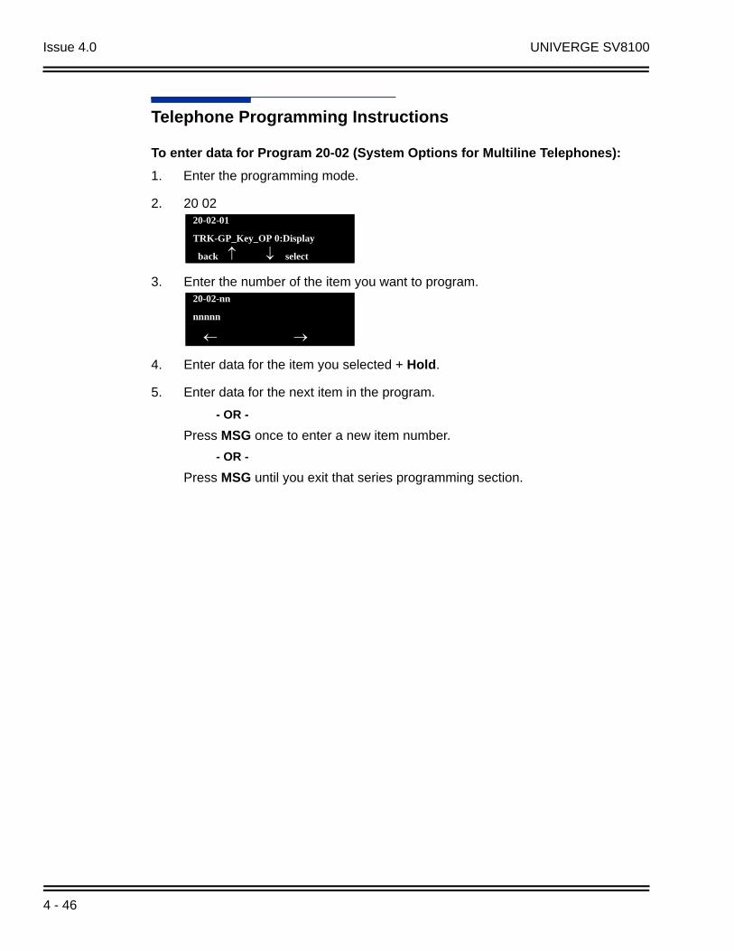
Issue 4.0 UNIVERGE SV8100
Telephone Programming Instructions
To enter data for Program 20-02 (System Options for Multiline Telephones):
1. Enter the programming mode.
2. 20 02
3. Enter the number of the item you want to program.
4. Enter data for the item you selected + Hold.
5. Enter data for the next item in the program.
- OR -
Press MSG once to enter a new item number.
- OR -
Press MSG until you exit that series programming section.
20-02-01
TRK-GP_Key_OP 0:Display
back select
20-02-nn
nnnnn
4 - 46
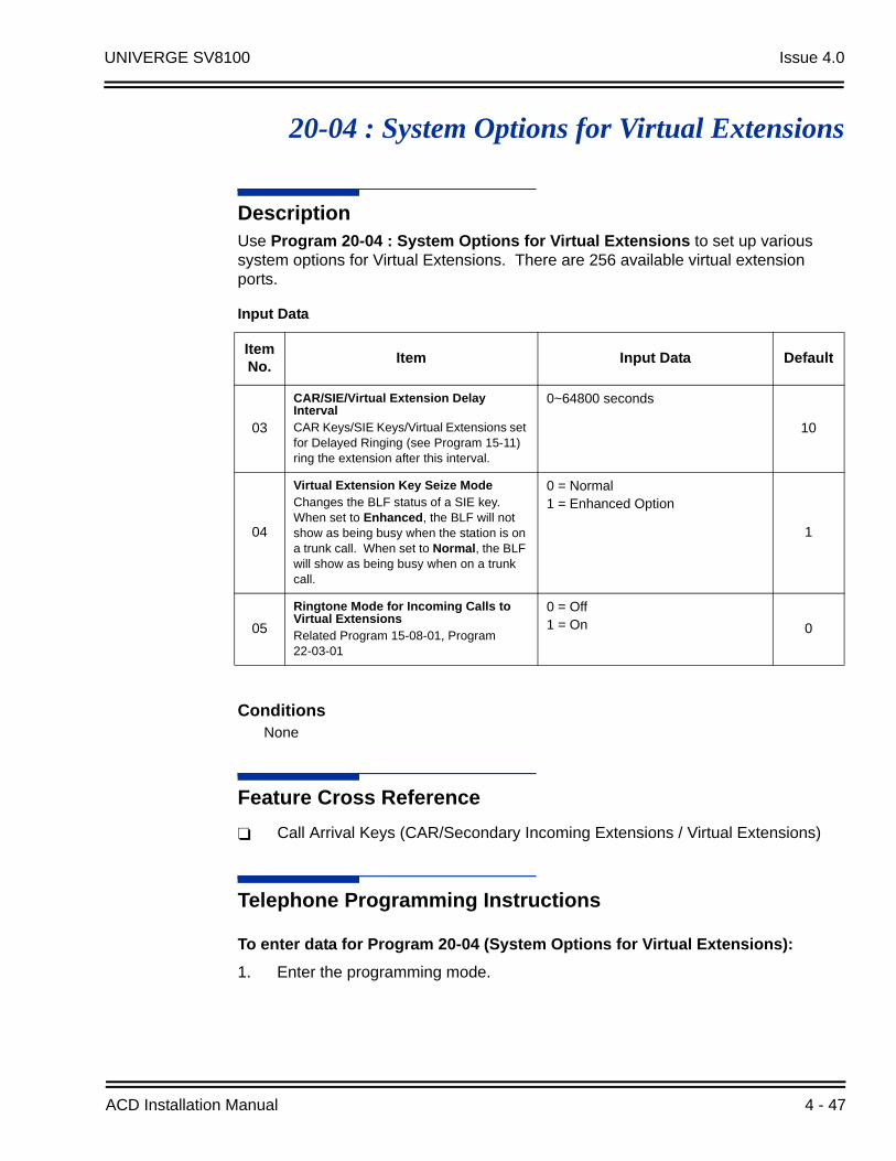
UNIVERGE SV8100 Issue 4.0
20-04 : System Options for Virtual Extensions
DescriptionUse Program 20-04 : System Options for Virtual Extensions to set up various system options for Virtual Extensions. There are 256 available virtual extension ports.
ConditionsNone
Feature Cross Reference
Call Arrival Keys (CAR/Secondary Incoming Extensions / Virtual Extensions)
Telephone Programming Instructions
To enter data for Program 20-04 (System Options for Virtual Extensions):
1. Enter the programming mode.
Input Data
Item No.
Item Input Data Default
03
CAR/SIE/Virtual Extension Delay IntervalCAR Keys/SIE Keys/Virtual Extensions set for Delayed Ringing (see Program 15-11) ring the extension after this interval.
0~64800 seconds
10
04
Virtual Extension Key Seize ModeChanges the BLF status of a SIE key. When set to Enhanced, the BLF will not show as being busy when the station is on a trunk call. When set to Normal, the BLF will show as being busy when on a trunk call.
0 = Normal1 = Enhanced Option
1
05
Ringtone Mode for Incoming Calls to Virtual ExtensionsRelated Program 15-08-01, Program 22-03-01
0 = Off1 = On 0
ACD Installation Manual 4 - 47

Issue 4.0 UNIVERGE SV8100
2. 20 04
3. Enter the number of the item you want to program.
4. Enter data for the item you selected + Hold.
5. Enter data for the next item in the program.
- OR -
Press MSG once to enter a new item number.
- OR -
Press MSG until you exit that series programming section.
20-04-01
V-Ext.Answer 1:Keep
20-04-nn
nnnnn
4 - 48
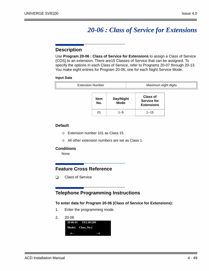
UNIVERGE SV8100 Issue 4.0
20-06 : Class of Service for Extensions
DescriptionUse Program 20-06 : Class of Service for Extensions to assign a Class of Service (COS) to an extension. There are15 Classes of Service that can be assigned. To specify the options in each Class of Service, refer to Programs 20-07 through 20-13. You make eight entries for Program 20-06, one for each Night Service Mode.
Default
Extension number 101 as Class 15.
All other extension numbers are set as Class 1.
ConditionsNone
Feature Cross Reference
Class of Service
Telephone Programming Instructions
To enter data for Program 20-06 (Class of Service for Extensions):
1. Enter the programming mode.
2. 20 06
Input Data
Extension Number Maximum eight digits
Item No.
Day/NightMode
Class of Service for Extensions
01 1~8 1~15
20-06-01 TEL301200
Mode1 Class_No.1
ACD Installation Manual 4 - 49
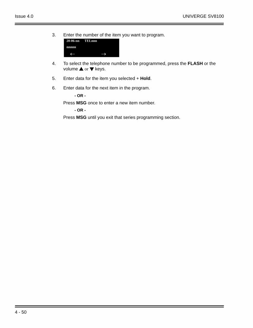
Issue 4.0 UNIVERGE SV8100
3. Enter the number of the item you want to program.
4. To select the telephone number to be programmed, press the FLASH or the volume or keys.
5. Enter data for the item you selected + Hold.
6. Enter data for the next item in the program.
- OR -
Press MSG once to enter a new item number.
- OR -
Press MSG until you exit that series programming section.
20-06-nn TELnnn
nnnnn
4 - 50

UNIVERGE SV8100 Issue 4.0
20-13 : Class of Service Options (Supplementary Service)
DescriptionUse Program 20-13 : Class of Service Options (Supplementary Service) to define the supplementary feature availability for each extension Class of Service (COS).
Input Data
Class of Service Number 01~15
Item No.
Item Input Data
DefaultRelated
ProgrammingCOS 01~14
COS 15
01Long Conversation AlarmTurns off or on the Warning Tone for Long Conversation (not for single line telephones).
0 = Off1 = On 0 0
02Long Conversation Cutoff (Incoming)Turns off or on an extension ability to use Long Conversation Cutoff for incoming calls.
0 = Off1 = On 0 0
03Long Conversation Cutoff (Outgoing)Turns off or on an extension ability to use Long Conversation Cutoff for outgoing calls.
0 = Off1 = On 0 0
04Call Forward/DND Override (Bypass Call)Turns off or on an extension ability to use Call Forwarding/DND Override.
0 = Off1 = On 1 1
05Intercom Off-Hook SignalingTurns off or on an extension ability to receive Off-Hook signals.
0 = Off1 = On 1 1
06Automatic Off Hook Signaling (Automatic Override)Allows a busy extension the ability to manually (0) or automatically (1) receive off-hook signals.
0 = Off1 = On 1 1
07Message WaitingTurns off or on an extension ability to leave Message Waiting.
0 = Off1 = On 1 1
08ConferenceTurns off or on an extension ability to initiate a conference or Meet-Me Conference.
0 = Off1 = On 1 1
09Privacy ReleaseTurns off or on an extension ability to initiate a Voice Call Conference.
0 = Off1 = On 1 1
10Barge-in MonitorEnables the extension Barge-in Mode to be Speech mode (0) or Monitor mode (1).
0 = Speech1 = Monitor 0 0 20-13-45
ACD Installation Manual 4 - 51

Issue 4.0 UNIVERGE SV8100
11Room Monitor, Initiating ExtensionTurns off or on an extension ability to Room Monitor other extensions.
0 = Off1 = On 0 0
12Room Monitor, Extension Being MonitoredTurn off or on an extension ability to be monitored by other extensions.
0 = Off1 = On 0 0
13
Continued Dialing (DTMF) Signal on ICM CallTurn off or on an extension ability to use Continued Dialing, which allows DTMF signal sending while talking on extension.
0 = Off1 = On 1 1
14Department Calling (PLT No Called Extension)Turns off or on an extension ability to call a Department Group Pilot.
0 = Off1 = On 1 1
15Barge In, InitiateTurns off or on an extension user ability to barge in on other's calls.
0 = Off1 = On 0 0
16Barge In, ReceiveTurns off or on an extension ability to have other extensions barge in on calls.
0 = Off1 = On 0 0
17
Barge-in Tone/Display (Intrusion Tone)Turns off or on the Barge In tone. If on, callers hear an alert tone and their display indicates the Barge In when another extension barges into their conversation. If off, there is no alert tone or display indication.
0 = Off1 = On 1 1
18
Programmable Function Key Programming (General Level)Turns off or on an extension user ability to program General function keys using Service Code 751 (by default). (Refer to Program 20-07-10 for Service Code 752.)
0 = Off1 = On 1 1
19Selectable Display Messaging (Text Messaging)Turns off or on an extension user ability to use Selectable Display Messaging.
0 = Off1 = On 1 1
20
Account Code/Toll Restriction Operator Alert (Restricted Operation Transfer)Turns off or on operator alert when an extension user improperly enters an Account Code or violates Toll Restriction.
0 = Off1 = On 0 0
21Extension NameTurns off or on an extension user ability to program its name.
0 = Off1 = On 1 1
22Busy Status Display (Called Party Status)Turns off or on the ability to display the detailed state of the called party.
0 = Off1 = On 0 0 20-13-06
Item No.
Item Input Data
DefaultRelated
ProgrammingCOS 01~14
COS 15
4 - 52
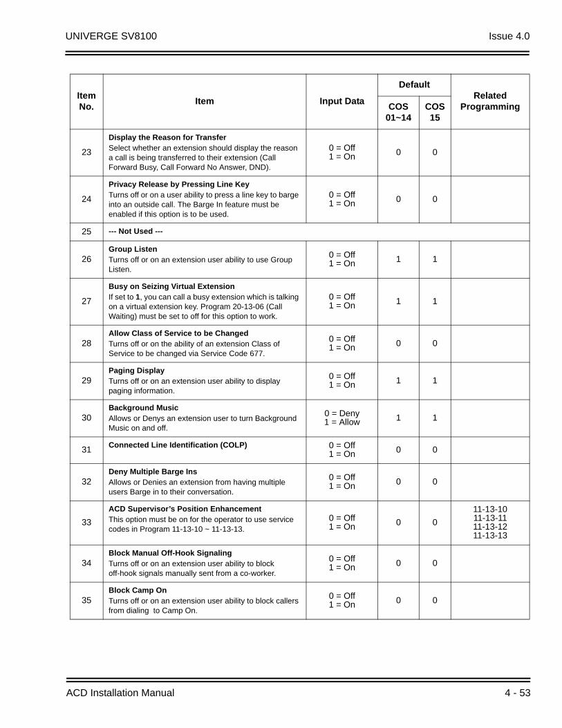
UNIVERGE SV8100 Issue 4.0
23
Display the Reason for TransferSelect whether an extension should display the reason a call is being transferred to their extension (Call Forward Busy, Call Forward No Answer, DND).
0 = Off1 = On 0 0
24
Privacy Release by Pressing Line KeyTurns off or on a user ability to press a line key to barge into an outside call. The Barge In feature must be enabled if this option is to be used.
0 = Off1 = On 0 0
25 --- Not Used ---
26Group ListenTurns off or on an extension user ability to use Group Listen.
0 = Off1 = On 1 1
27
Busy on Seizing Virtual ExtensionIf set to 1, you can call a busy extension which is talking on a virtual extension key. Program 20-13-06 (Call Waiting) must be set to off for this option to work.
0 = Off1 = On 1 1
28Allow Class of Service to be ChangedTurns off or on the ability of an extension Class of Service to be changed via Service Code 677.
0 = Off1 = On 0 0
29Paging DisplayTurns off or on an extension user ability to display paging information.
0 = Off1 = On 1 1
30Background MusicAllows or Denys an extension user to turn Background Music on and off.
0 = Deny1 = Allow 1 1
31Connected Line Identification (COLP) 0 = Off
1 = On 0 0
32Deny Multiple Barge InsAllows or Denies an extension from having multiple users Barge in to their conversation.
0 = Off1 = On 0 0
33
ACD Supervisor’s Position EnhancementThis option must be on for the operator to use service codes in Program 11-13-10 ~ 11-13-13.
0 = Off1 = On 0 0
11-13-1011-13-1111-13-1211-13-13
34Block Manual Off-Hook SignalingTurns off or on an extension user ability to block off-hook signals manually sent from a co-worker.
0 = Off1 = On 0 0
35Block Camp OnTurns off or on an extension user ability to block callers from dialing to Camp On.
0 = Off1 = On 0 0
Item No.
Item Input Data
DefaultRelated
ProgrammingCOS 01~14
COS 15
ACD Installation Manual 4 - 53

Issue 4.0 UNIVERGE SV8100
36
Call Duration Timer DisplayTurns off or on an extension display of the Call Duration Time. The system waits until the interdigit time (Program 21-01-01) expires before beginning this timer.
0 = Off1 = On 1 1
37 --- Not Used ---
38Headset RingingTurn off or on an extension user ability to use the Headset ringing.
0 = Off1 = On 0 0
39
ACD Queue Status DisplayTurns off or on the ACD Queue Status Display for an extension Class of Service. Any extension which has this option enabled also hears the queue alarm.
0 = Off1 = On 0 0
40Do Not DisturbTurn off or on and extension user ability to set or cancel Do Not Disturb.
0 = Off1 = On 1 1 11-11-08
15-07-03
41Voice Mail Message Indication on DSSTurn off or on the Voice Mail Message Indication for an extension on a DSS console.
0 = Off1 = On 0 0
42Extension Data Swap EnablingTurn off or on an extension user ability to use Extension Data Swap.
0 = Off1 = On 1 1 11-15-12
43 --- Not Used ---
44Live Monitor EnablingTurn off or on an extension user ability to use Live Monitor.
0 = Off1 = On 1 1
45
MIC Key Mode while Call MonitoringSet per class of service, when in Call Monitoring Mode determines if the monitored parties receives the barge in alert tone when Coaching Mode is enabled.
0 = Enable1 = Disable 1 1 20-13-10
47
Station Number DisplayDetermine if a station Number will be displayed (On) or not displayed (Off) in the LCD when the phone is in an idle state.
0 = Off1 = On 1 1
48
Station Name DisplayDetermine if a station Name will be displayed (On) or not displayed (Off) in the LCD when the phone is in an idle state.
0 = Off1 = On 1 1
49BLF Indication on CO Incoming StateDetermine if a BLF of the station will light when a Normal CO call is ringing the phone.
0 = Off1 = On 0 0
Item No.
Item Input Data
DefaultRelated
ProgrammingCOS 01~14
COS 15
4 - 54

UNIVERGE SV8100 Issue 4.0
ConditionsNone
Feature Cross Reference
Class of Service
Telephone Programming Instructions
To enter data for Program 20-13 [Class of Service Options (Supplementary Service)]:
1. Enter the programming mode.
2. 20 13
50AIC Agent display which call is fromDetermine if the station logged in via AIC codes will show which queue the call is coming from.
0 = Off1 = On 1 1
51Number and Name appear in the DirectoryDetermine if an extension name and number will be listed (On) or unlisted (Off) in the directory.
0 = Off1 = On 1 1
52
VoIP All DSP Busy DisplaySet whether “All DSP Busy” alarm displays on LCD when the caller makes an IP call and there is no VoIP DSP resource.
0 = Disable1 = Enable 1 1
53Language Selection for Specific Extension 0 = Disable
1 = Enable 0 011-11-6815-02-0147-02-16
54
Call Waiting for Standard SIP TerminalSet up Call Waiting (off-hook signaling) for standard SIP terminal. When set to enable, this Program looks at Programs 20-13-05, 20-13-06, 20-09-01, and 20-09-07.
0 = Disable1 = Enable 0 0
20-09-0120-09-0720-13-0520-13-06
Item No.
Item Input Data
DefaultRelated
ProgrammingCOS 01~14
COS 15
20-13-01 FCTN Cls1
Long_Conv.Alarm 1:On
back select
ACD Installation Manual 4 - 55

Issue 4.0 UNIVERGE SV8100
3. Enter the number of the item you want to program.
4. To select the Class of Service number to be programmed, press the FLASH or the volume or keys.
5. Enter data for the item you selected + Hold.
6. Enter data for the next item in the program.
- OR -
Press MSG once to enter a new item number.
- OR -
Press MSG until you exit that series programming section.
20-13-nn FCTN Clsnn
nnnnn
4 - 56
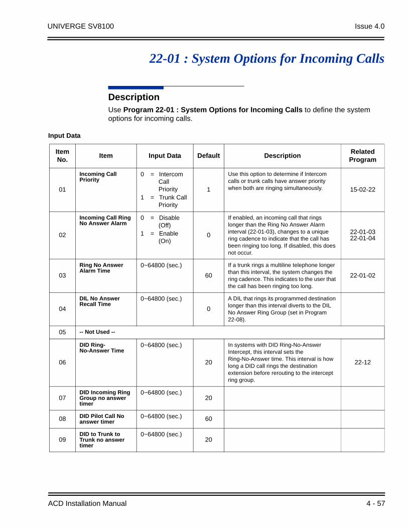
UNIVERGE SV8100 Issue 4.0
22-01 : System Options for Incoming Calls
DescriptionUse Program 22-01 : System Options for Incoming Calls to define the system options for incoming calls.
Input Data
Item No.
Item Input Data Default DescriptionRelated Program
01
Incoming Call Priority
0 = Intercom Call Priority
1 = Trunk Call Priority
1
Use this option to determine if Intercom calls or trunk calls have answer priority when both are ringing simultaneously. 15-02-22
02
Incoming Call Ring No Answer Alarm
0 = Disable (Off)
1 = Enable (On)
0
If enabled, an incoming call that rings longer than the Ring No Answer Alarm interval (22-01-03), changes to a unique ring cadence to indicate that the call has been ringing too long. If disabled, this does not occur.
22-01-0322-01-04
03
Ring No Answer Alarm Time
0~64800 (sec.)
60
If a trunk rings a multiline telephone longer than this interval, the system changes the ring cadence. This indicates to the user that the call has been ringing too long.
22-01-02
04
DIL No Answer Recall Time
0~64800 (sec.)
0
A DIL that rings its programmed destination longer than this interval diverts to the DIL No Answer Ring Group (set in Program 22-08).
05 -- Not Used --
06
DID Ring-No-Answer Time
0~64800 (sec.)
20
In systems with DID Ring-No-Answer Intercept, this interval sets the Ring-No-Answer time. This interval is how long a DID call rings the destination extension before rerouting to the intercept ring group.
22-12
07DID Incoming Ring Group no answer timer
0~64800 (sec.)20
08 DID Pilot Call No answer timer
0~64800 (sec.) 60
09DID to Trunk to Trunk no answer timer
0~64800 (sec.)20
ACD Installation Manual 4 - 57
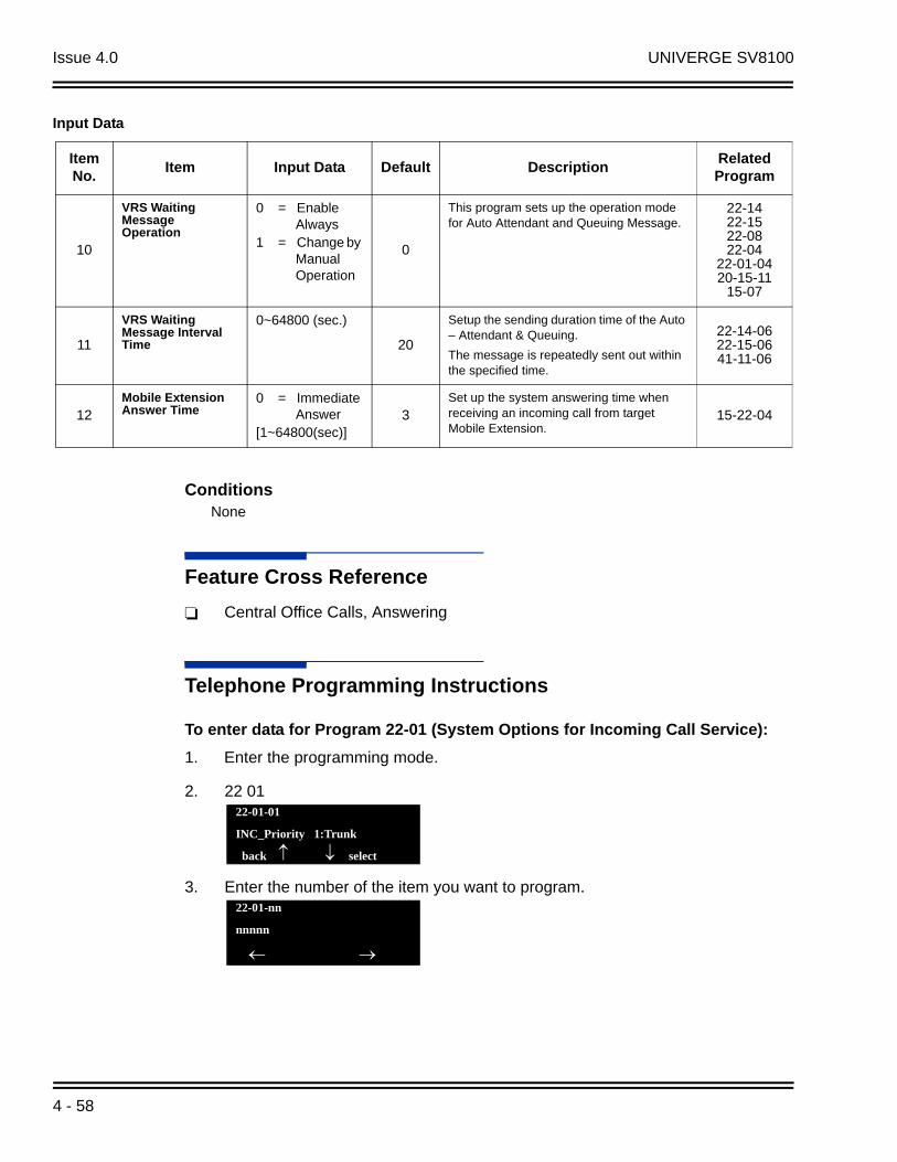
Issue 4.0 UNIVERGE SV8100
ConditionsNone
Feature Cross Reference
Central Office Calls, Answering
Telephone Programming Instructions
To enter data for Program 22-01 (System Options for Incoming Call Service):
1. Enter the programming mode.
2. 22 01
3. Enter the number of the item you want to program.
10
VRS Waiting Message Operation
0 = Enable Always
1 = Change by Manual Operation
0
This program sets up the operation mode for Auto Attendant and Queuing Message.
22-1422-1522-0822-04
22-01-0420-15-11
15-07
11
VRS Waiting Message Interval Time
0~64800 (sec.)
20
Setup the sending duration time of the Auto – Attendant & Queuing.
The message is repeatedly sent out within the specified time.
22-14-0622-15-0641-11-06
12Mobile Extension Answer Time
0 = Immediate Answer
[1~64800(sec)]3
Set up the system answering time when receiving an incoming call from target Mobile Extension.
15-22-04
Input Data
Item No.
Item Input Data Default DescriptionRelated Program
22-01-01
INC_Priority 1:Trunk
back select
22-01-nn
nnnnn
4 - 58

UNIVERGE SV8100 Issue 4.0
4. Enter data for the item you selected + Hold.
5. Enter data for the next item in the program.
- OR -
Press MSG once to enter a new item number.
- OR -
Press MSG until you exit that series programming section.
ACD Installation Manual 4 - 59

Issue 4.0 UNIVERGE SV8100
THIS PAGE INTENTIONALLY LEFT BLANK
4 - 60

UNIVERGE SV8100 Issue 4.0
22-03 : Trunk Ring Tone Range
DescriptionUse Program 22-03 : Trunk Ring Tone Range to select the ring tone range for the trunk. The trunk uses a ring tone in the range selected when it rings an extension. There are eight ring tones available. Customize the Trunk Ring Tones in Program 82-01.
Input Data
Trunk Port Number 001~200
Item No.
Ring Tone Pattern Default DescriptionRelated Program
01
0~3 = Tone Pattern 1~44~8 = Melody 1~59~12 = Tone Pattern
5~8
0
Use this program to select the ring tone range for the trunk. The trunk uses a ring tone in the range selected when it rings an extension. Eight ring tones are available.
15-02
Table 4-3 Program 22 : 03 – Incoming Signal Frequency Patterns
Incoming Signal Frequency Pattern
Type Frequency 1 Frequency 2 Modulation
Pattern 1High
MiddleLow
1100Hz660Hz520Hz
1400Hz760Hz660Hz
16Hz16Hz16Hz
Pattern 2High
MiddleLow
1100Hz660Hz520Hz
1400Hz760Hz660Hz
8Hz8Hz8Hz
Pattern 3High
MiddleLow
200014001100
760660540
16Hz16Hz16Hz
Pattern 4High
MiddleLow
200014001100
760660540
8Hz8Hz8Hz
Pattern 5High
MiddleLow
1400Hz760Hz660Hz
540Hz540Hz540Hz
16Hz16Hz16Hz
Pattern 6High
MiddleLow
1400Hz760Hz660Hz
540Hz540Hz540Hz
8Hz8Hz8Hz
ACD Installation Manual 4 - 61
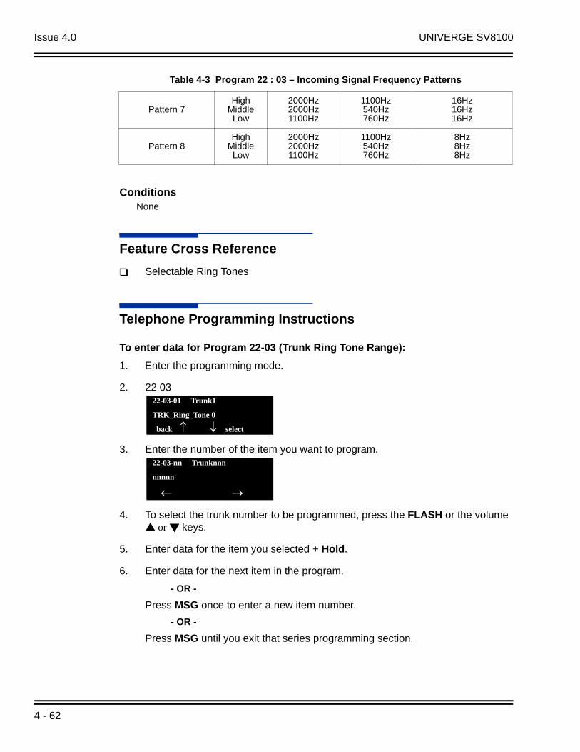
Issue 4.0 UNIVERGE SV8100
ConditionsNone
Feature Cross Reference
Selectable Ring Tones
Telephone Programming Instructions
To enter data for Program 22-03 (Trunk Ring Tone Range):
1. Enter the programming mode.
2. 22 03
3. Enter the number of the item you want to program.
4. To select the trunk number to be programmed, press the FLASH or the volume or keys.
5. Enter data for the item you selected + Hold.
6. Enter data for the next item in the program.
- OR -
Press MSG once to enter a new item number.
- OR -
Press MSG until you exit that series programming section.
Pattern 7High
MiddleLow
2000Hz2000Hz1100Hz
1100Hz540Hz760Hz
16Hz16Hz16Hz
Pattern 8High
MiddleLow
2000Hz2000Hz1100Hz
1100Hz540Hz760Hz
8Hz8Hz8Hz
22-03-01 Trunk1
TRK_Ring_Tone 0
back select
22-03-nn Trunknnn
nnnnn
Table 4-3 Program 22 : 03 – Incoming Signal Frequency Patterns
4 - 62

UNIVERGE SV8100 Issue 4.0
22-05 : Incoming Trunk Ring Group Assignment
DescriptionUse Program 22-05 : Incoming Trunk Ring Group Assignment to assign trunks to incoming Ring Groups. There are 100 available Ring Groups.
ConditionsNone
Feature Cross Reference
Ring Groups
Telephone Programming Instructions
To enter data for Program 22-05 (Incoming Trunk Ring Group Assignment):
1. Enter the programming mode.
2. 22 05
Input Data
Trunk Port Number 001~200
Item No.
Day/Night Mode
Incoming Group Number
Default DescriptionRelated Program
01 1~8
0 (No Setting)001~100(Incoming Group)101 (Not Used)102 (In-Skin/ External Voice Mail or VM8000 InMail)103 (Centralized VM)
1
Use this program to assign Normal Ring Trunks (22-02) to Incoming Ring Groups (22-04). 22-04
22-06
22-05-01 Trunk1
Mode1 =1
back select
ACD Installation Manual 4 - 63

Issue 4.0 UNIVERGE SV8100
3. Enter the number of the item you want to program.
4. To select the trunk number to be programmed, press the FLASH or the volume or keys.
5. Enter data for the item you selected + Hold.
6. Enter data for the next item in the program.
- OR -
Press MSG once to enter a new item number.
- OR -
Press MSG until you exit that series programming section.
22-05-nn Trunknnn
nnnnn
4 - 64
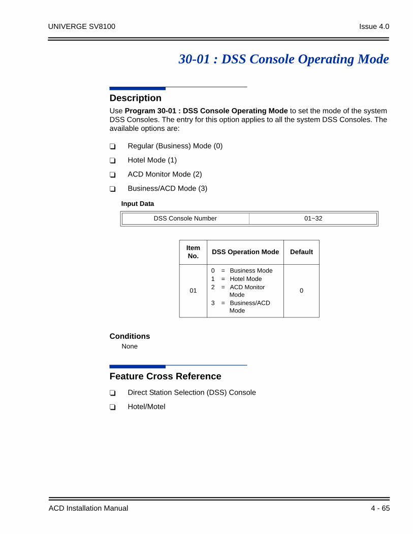
UNIVERGE SV8100 Issue 4.0
30-01 : DSS Console Operating Mode
DescriptionUse Program 30-01 : DSS Console Operating Mode to set the mode of the system DSS Consoles. The entry for this option applies to all the system DSS Consoles. The available options are:
Regular (Business) Mode (0)
Hotel Mode (1)
ACD Monitor Mode (2)
Business/ACD Mode (3)
ConditionsNone
Feature Cross Reference
Direct Station Selection (DSS) Console
Hotel/Motel
Input Data
DSS Console Number 01~32
Item No.
DSS Operation Mode Default
01
0 = Business Mode1 = Hotel Mode2 = ACD Monitor
Mode3 = Business/ACD
Mode
0
ACD Installation Manual 4 - 65

Issue 4.0 UNIVERGE SV8100
Telephone Programming Instructions
To enter data for Program 30-01 (DSS Console Operating Mode):
1. Enter the programming mode.
2. 30 01
3. Enter the number of the item you want to program.
4. Enter data for the item you selected + Hold.
5. Enter data for the next item in the program.
- OR -
Press MSG once to enter a new item number.
- OR -
Press MSG until you exit that series programming section.
30-01-01
Operation_Mode0:Business
back select
30-01-nn
nnnnn
4 - 66

UNIVERGE SV8100 Issue 4.0
30-02 : DSS Console Extension Assignment
DescriptionUse Program 30-02 : DSS Console Extension Assignment to identify which extensions have DSS Consoles connected.
Up to 32 different extensions with DSS Consoles can be set up. A single extension can have up to four 60-button DSS Consoles (32 is the maximum allowed per system).
When programming, each extension/DSS Console(s) combination is called a Console Number. There are 32 Console Numbers (1~32). Console Numbers can be assigned to extensions. When entering data, the assignment for Console Number 1 is normally made first.
ConditionsNone
Feature Cross Reference
Direct Station Selection (DSS) Console
Input Data
60-button DSS Console Number 01~32
Item No.
Item Description Default
01Extension Number The extension number for the multiline terminal
connected with the DSS console (up to eight digits)No
Setting
ACD Installation Manual 4 - 67

Issue 4.0 UNIVERGE SV8100
Telephone Programming Instructions
To enter data for Program 30-02 (DSS Console Extension Assignment):
1. Enter the programming mode.
2. 30 02
3. Enter the number of the item you want to program.
4. To select the DSS number to be programmed, press the FLASH or the volume or keys.
5. Enter data for the item you selected + Hold.
6. Enter data for the next item in the program.
- OR -
Press MSG once to enter a new item number.
- OR -
Press MSG until you exit that series programming section.
30-02-01 DSS1
Ext.Number
back select
30-02-nn DSSnn
nnnnn
4 - 68

UNIVERGE SV8100 Issue 4.0
30-03 : DSS Console Key Assignment
DescriptionUse Program 30-03 : DSS Console Key Assignments to customize the key assignments for 60-button DSS Consoles. A DSS Console key can have any function up to four digits long (e.g., extension number or Service Code).
To prevent lamp problems when reassigning DSS Console keys, clearing an extension programmed key before reassigning it is recommended [Enter key to be cleared + 00 or 00 (If using WebPro or PC Programming, delete the key assignments and upload the change to the system before proceeding.)] Without clearing an extension key first, the DSS Console may not show the correct lamp display, although the DSS function works correctly.
If you are programming the system from the extension to which the DSS Console is connected, either by phone or using the WebPro or PC Program, you may need to unplug the DSS and plug it back in to reset the console's lamping.
Input Data
Index 1
DSS Console Number 01~32
Index 2
Item No.
Key Number Function Number Additional Data
01 001~114
0~99 (General Functional Level)
97 = Door Box Access key (additional data: 1~8 Door Box No.)
00 ~ 99 (Appearance Functional Level)
Refer to Function Number List on the following pages.
ACD Installation Manual 4 - 69

Issue 4.0 UNIVERGE SV8100
Function Number List[1] General functional level (00~99)
Function Number
Function Additional Data LED Indication
00 --- Not Used ---
01
DSS / One-Touch Extension Number or any Numbers (up to 24 digits)
Red On: Extension BusyOff: Extension IdleRapid Blink (Red): DND or Call Forward
02Microphone Key (ON/OFF) Red On: Mic On
Off: Mic Off
03 DND Key Red On: DND
04BGM (ON/OFF) Red On: BGM On
Off: BGM Off
05 Headset Red On: Under Headset Operation
06 Transfer Key None
07 Conference Key Red On: Under Conference Operation
08Incoming Call Log Rapid Blink (Red): New Call Log
Red On: Call LogOff: No Call Log
09 Day/Night Mode Switch Mode Number (1~8) Red On: On mode
10Call Forward – Immediate Slow Blink (Red): Forwarding State
Rapid Blink (Red): Forwarded State
11Call Forward – Busy Slow Blink (Red): Forwarding State
Rapid Blink (Red): Forwarded State
12Call Forward – No Answer Slow Blink (Red): Forwarding State
Rapid Blink (Red): Forwarded State
13Call Forward – Busy/No Answer
Slow Blink (Red): Forwarding StateRapid Blink (Red): Forwarded State
14Call Forward – Both Ring Slow Blink (Red): Forwarding State
Rapid Blink (Red): Forwarded State
15Follow Me Slow Blink (Red): Forwarding State
Rapid Blink (Red): Forwarded State
18 Text Message Setup Message Numbers (01~20) Red On: Feature active by Function Key
19 External Group Paging External Paging Number(1~8)
Red On: Active
4 - 70
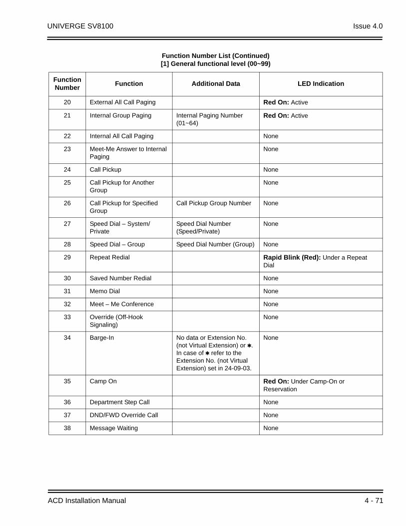
UNIVERGE SV8100 Issue 4.0
20 External All Call Paging Red On: Active
21 Internal Group Paging Internal Paging Number(01~64)
Red On: Active
22 Internal All Call Paging None
23 Meet-Me Answer to Internal Paging
None
24 Call Pickup None
25 Call Pickup for Another Group
None
26 Call Pickup for Specified Group
Call Pickup Group Number None
27 Speed Dial – System/Private
Speed Dial Number (Speed/Private)
None
28 Speed Dial – Group Speed Dial Number (Group) None
29 Repeat Redial Rapid Blink (Red): Under a RepeatDial
30 Saved Number Redial None
31 Memo Dial None
32 Meet – Me Conference None
33 Override (Off-Hook Signaling)
None
34 Barge-In No data or Extension No. (not Virtual Extension) or . In case of refer to the Extension No. (not Virtual Extension) set in 24-09-03.
None
35 Camp On Red On: Under Camp-On or Reservation
36 Department Step Call None
37 DND/FWD Override Call None
38 Message Waiting None
Function Number List (Continued)[1] General functional level (00~99)
Function Number
Function Additional Data LED Indication
ACD Installation Manual 4 - 71
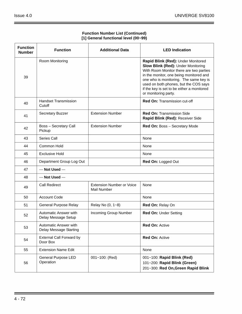
Issue 4.0 UNIVERGE SV8100
39
Room Monitoring Rapid Blink (Red): Under MonitoredSlow Blink (Red): Under Monitoring With Room Monitor there are two parties in the monitor, one being monitored and one who is monitoring. The same key is used on both phones, but the COS says if the key is set to be either a monitored or monitoring party.
40Handset Transmission Cutoff
Red On: Transmission cut-off
41Secretary Buzzer Extension Number Red On: Transmission Side
Rapid Blink (Red): Receiver Side
42Boss – Secretary Call Pickup
Extension Number Red On: Boss – Secretary Mode
43 Series Call None
44 Common Hold None
45 Exclusive Hold None
46 Department Group Log Out Red On: Logged Out
47 --- Not Used ---
48 --- Not Used ---
49Call Redirect Extension Number or Voice
Mail NumberNone
50 Account Code None
51 General Purpose Relay Relay No (0, 1~8) Red On: Relay On
52Automatic Answer with Delay Message Setup
Incoming Group Number Red On: Under Setting
53Automatic Answer with Delay Message Starting
Red On: Active
54External Call Forward by Door Box
Red On: Active
55 Extension Name Edit None
56
General Purpose LED Operation
001~100: (Red) 001~100: Rapid Blink (Red)101~200: Rapid Blink (Green)201~300: Red On,Green Rapid Blink
Function Number List (Continued)[1] General functional level (00~99)
Function Number
Function Additional Data LED Indication
4 - 72
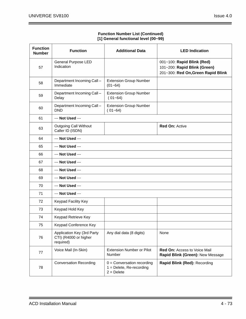
UNIVERGE SV8100 Issue 4.0
57
General Purpose LED Indication
001~100: Rapid Blink (Red)101~200: Rapid Blink (Green)201~300: Red On,Green Rapid Blink
58Department Incoming Call – Immediate
Extension Group Number (01~64)
59Department Incoming Call – Delay
Extension Group Number ( 01~64)
60Department Incoming Call – DND
Extension Group Number ( 01~64)
61 --- Not Used ---
63Outgoing Call Without Caller ID (ISDN)
Red On: Active
64 --- Not Used ---
65 --- Not Used ---
66 --- Not Used ---
67 --- Not Used ---
68 --- Not Used ---
69 --- Not Used ---
70 --- Not Used ---
71 --- Not Used ---
72 Keypad Facility Key
73 Keypad Hold Key
74 Keypad Retrieve Key
75 Keypad Conference Key
76Application Key (3rd Party CTI) (R4000 or higher required)
Any dial data (8 digits) None
77Voice Mail (In-Skin) Extension Number or Pilot
NumberRed On: Access to Voice MailRapid Blink (Green): New Message
78Conversation Recording 0 = Conversation recording
1 = Delete, Re-recording2 = Delete
Rapid Blink (Red): Recording
Function Number List (Continued)[1] General functional level (00~99)
Function Number
Function Additional Data LED Indication
ACD Installation Manual 4 - 73
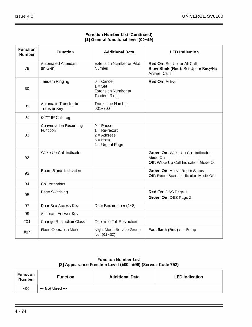
Issue 4.0 UNIVERGE SV8100
79Automated Attendant (In-Skin)
Extension Number or Pilot Number
Red On: Set Up for All CallsSlow Blink (Red): Set Up for Busy/No Answer Calls
80
Tandem Ringing 0 = Cancel1 = SetExtension Number to Tandem Ring
Red On: Active
81Automatic Transfer to Transfer Key
Trunk Line Number 001~200
82 Dterm IP Call Log
83
Conversation Recording Function
0 = Pause1 = Re-record2 = Address3 = Erase4 = Urgent Page
92Wake Up Call Indication Green On: Wake Up Call Indication
Mode OnOff: Wake Up Call Indication Mode Off
93Room Status Indication Green On: Active Room Status
Off: Room Status Indication Mode Off
94 Call Attendant
95Page Switching Red On: DSS Page 1
Green On: DSS Page 2
97 Door Box Access Key Door Box number (1~8)
99 Alternate Answer Key
#04 Change Restriction Class One-time Toll Restriction
#07Fixed Operation Mode Night Mode Service Group
No. (01~32)Fast flash (Red) : – Setup
Function Number List (Continued)[1] General functional level (00~99)
Function Number
Function Additional Data LED Indication
Function Number List[2] Appearance Function Level (00 - 99) (Service Code 752)
Function Number
Function Additional Data LED Indication
00 --- Not Used ---
4 - 74

UNIVERGE SV8100 Issue 4.0
Default
The DSS keys 01~60 of all DSS consoles = DSS/One-Touch key 101~160.
The DSS keys 61~114 of all DSS consoles = None
ConditionsNone
Feature Cross Reference
Direct Station Selection (DSS) Console
01 Trunk Key Trunk Number (001~200)
02 --- Not Used ---
03 --- Not Used ---
04 Park Key Park Number (01~64)
05 --- Not Used ---
06 Trunk Access Via Networking Network System Number (01~50)
07 Station Park Hold None
08 --- Not Used ---
10 --- Not Used ---
11 --- Not Used ---
12 --- Not Used ---
13 --- Not Used ---
14 --- Not Used ---
15 --- Not Used ---
16 --- Not Used ---
17 --- Not Used ---
18 --- Not Used ---
19 --- Not Used ---
Function Number List (Continued)[2] Appearance Function Level (00 - 99) (Service Code 752)
ACD Installation Manual 4 - 75

Issue 4.0 UNIVERGE SV8100
Telephone Programming Instructions
To enter data for Program 30-03 (DSS Console Key Assignment):
1. Enter the programming mode.
2. 30 03
3. Enter the number of the item you want to program.
4. To select the DSS number to be programmed, press the FLASH or the volume or keys.
5. Enter data for the item you selected + Hold.
6. Enter data for the next item in the program.
- OR -
Press MSG once to enter a new item number.
- OR -
Press MSG until you exit that series programming section.
30-03-01 DSS1
KY01 = 01
back select
30-03-nn DSSnn
nnnnn
4 - 76
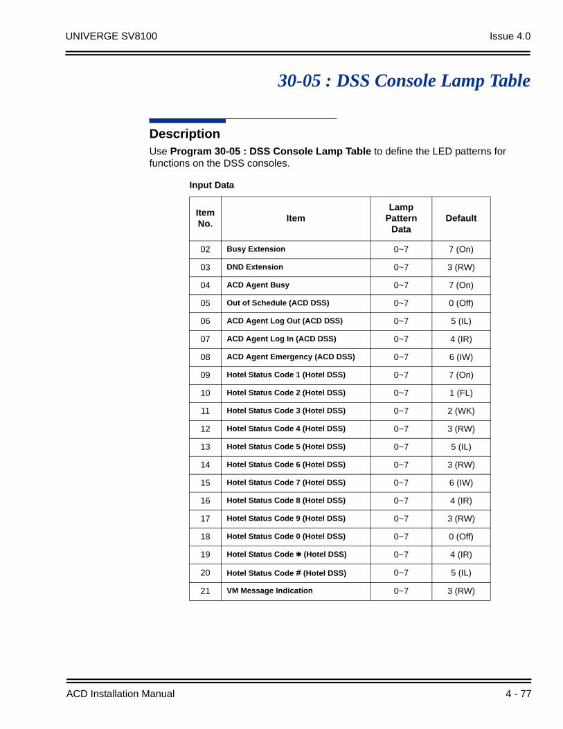
UNIVERGE SV8100 Issue 4.0
30-05 : DSS Console Lamp Table
DescriptionUse Program 30-05 : DSS Console Lamp Table to define the LED patterns for functions on the DSS consoles.
Input Data
Item No.
ItemLamp
Pattern Data
Default
02 Busy Extension 0~7 7 (On)
03 DND Extension 0~7 3 (RW)
04 ACD Agent Busy 0~7 7 (On)
05 Out of Schedule (ACD DSS) 0~7 0 (Off)
06 ACD Agent Log Out (ACD DSS) 0~7 5 (IL)
07 ACD Agent Log In (ACD DSS) 0~7 4 (IR)
08 ACD Agent Emergency (ACD DSS) 0~7 6 (IW)
09 Hotel Status Code 1 (Hotel DSS) 0~7 7 (On)
10 Hotel Status Code 2 (Hotel DSS) 0~7 1 (FL)
11 Hotel Status Code 3 (Hotel DSS) 0~7 2 (WK)
12 Hotel Status Code 4 (Hotel DSS) 0~7 3 (RW)
13 Hotel Status Code 5 (Hotel DSS) 0~7 5 (IL)
14 Hotel Status Code 6 (Hotel DSS) 0~7 3 (RW)
15 Hotel Status Code 7 (Hotel DSS) 0~7 6 (IW)
16 Hotel Status Code 8 (Hotel DSS) 0~7 4 (IR)
17 Hotel Status Code 9 (Hotel DSS) 0~7 3 (RW)
18 Hotel Status Code 0 (Hotel DSS) 0~7 0 (Off)
19 Hotel Status Code (Hotel DSS) 0~7 4 (IR)
20 Hotel Status Code # (Hotel DSS) 0~7 5 (IL)
21 VM Message Indication 0~7 3 (RW)
ACD Installation Manual 4 - 77
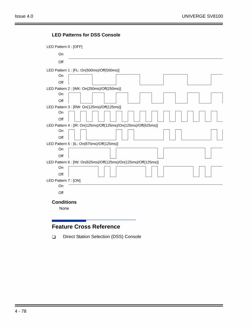
Issue 4.0 UNIVERGE SV8100
LED Patterns for DSS Console
ConditionsNone
Feature Cross Reference
Direct Station Selection (DSS) Console
LED Pattern 0 : [OFF]
On
Off
LED Pattern 1 : [FL: On(500ms)/Off(500ms)]
On
Off
LED Pattern 2 : [WK: On(250ms)/Off(250ms)]
On
Off
LED Pattern 3 : [RW: On(125ms)/Off(125ms)]
On
Off
LED Pattern 4 : [IR: On(125ms)/Off(125ms)/On(125ms)/Off(625ms)]
On
Off
LED Pattern 5 : [IL: On(875ms)/Off(125ms)]
On
Off
LED Pattern 6 : [IW: On(625ms)/Off(125ms)/On(125ms)/Off(125ms)]
On
Off
LED Pattern 7 : [ON]
On
Off
4 - 78
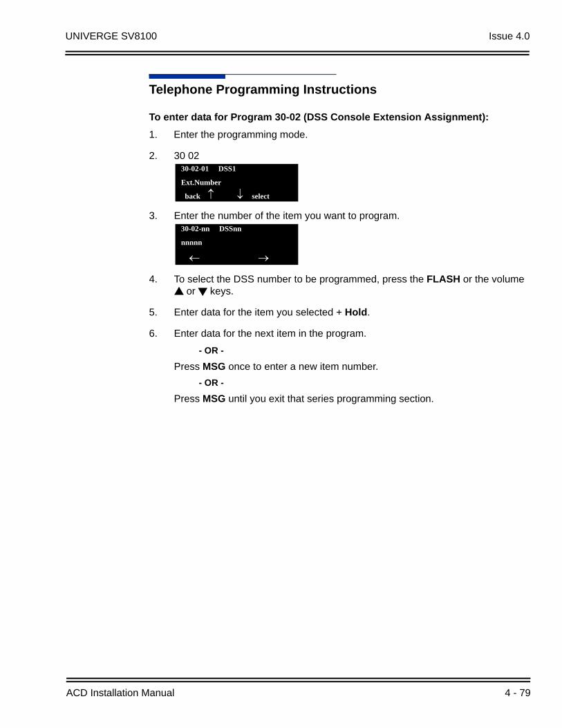
UNIVERGE SV8100 Issue 4.0
Telephone Programming Instructions
To enter data for Program 30-02 (DSS Console Extension Assignment):
1. Enter the programming mode.
2. 30 02
3. Enter the number of the item you want to program.
4. To select the DSS number to be programmed, press the FLASH or the volume or keys.
5. Enter data for the item you selected + Hold.
6. Enter data for the next item in the program.
- OR -
Press MSG once to enter a new item number.
- OR -
Press MSG until you exit that series programming section.
30-02-01 DSS1
Ext.Number
back select
30-02-nn DSSnn
nnnnn
ACD Installation Manual 4 - 79

Issue 4.0 UNIVERGE SV8100
THIS PAGE INTENTIONALLY LEFT BLANK
4 - 80
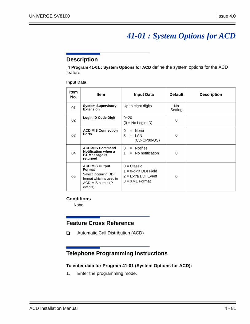
UNIVERGE SV8100 Issue 4.0
41-01 : System Options for ACD
DescriptionIn Program 41-01 : System Options for ACD define the system options for the ACD feature.
ConditionsNone
Feature Cross Reference
Automatic Call Distribution (ACD)
Telephone Programming Instructions
To enter data for Program 41-01 (System Options for ACD):
1. Enter the programming mode.
Input Data
Item No.
Item Input Data Default Description
01System Supervisory Extension
Up to eight digits No Setting
02Login ID Code Digit 0~20
(0 = No Login ID)0
03ACD MIS Connection Ports
0 = None3 = LAN
(CD-CP00-US)0
04ACD-MIS Command Notification when a BT Message is returned
0 = Notifies1 = No notification 0
05
ACD MIS Output FormatSelect incoming DDI format which is used in ACD-MIS output (P events).
0 = Classic1 = 8-digit DDI Field2 = Extra DDI Event3 = XML Format
0
ACD Installation Manual 4 - 81
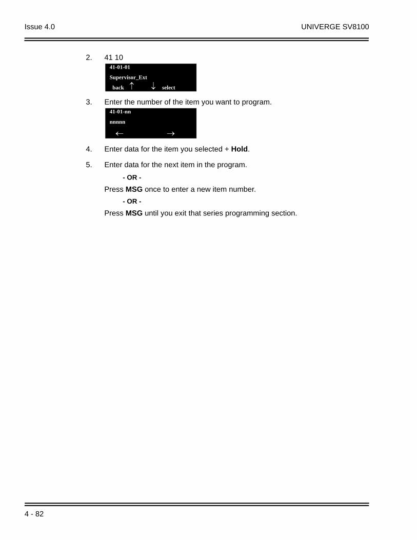
Issue 4.0 UNIVERGE SV8100
2. 41 10
3. Enter the number of the item you want to program.
4. Enter data for the item you selected + Hold.
5. Enter data for the next item in the program.
- OR -
Press MSG once to enter a new item number.
- OR -
Press MSG until you exit that series programming section.
41-01-01
Supervisor_Ext
back select
41-01-nn
nnnnn
4 - 82
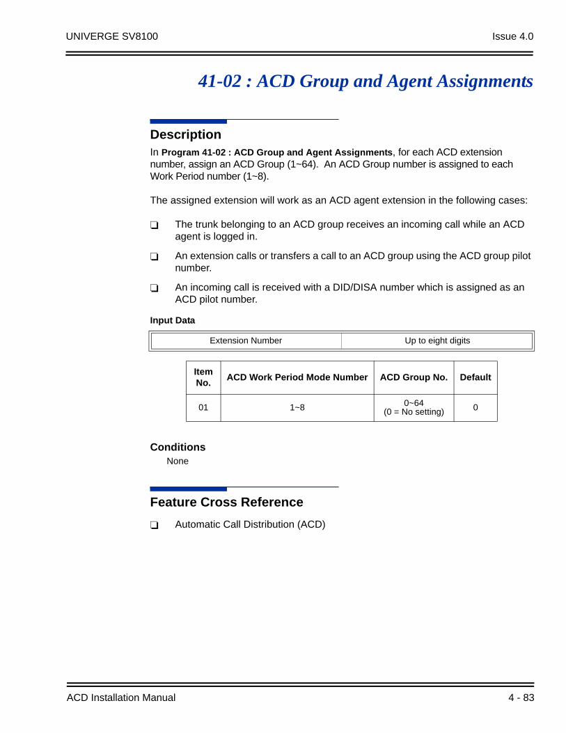
UNIVERGE SV8100 Issue 4.0
41-02 : ACD Group and Agent Assignments
DescriptionIn Program 41-02 : ACD Group and Agent Assignments, for each ACD extension number, assign an ACD Group (1~64). An ACD Group number is assigned to each Work Period number (1~8).
The assigned extension will work as an ACD agent extension in the following cases:
The trunk belonging to an ACD group receives an incoming call while an ACD agent is logged in.
An extension calls or transfers a call to an ACD group using the ACD group pilot number.
An incoming call is received with a DID/DISA number which is assigned as an ACD pilot number.
ConditionsNone
Feature Cross Reference
Automatic Call Distribution (ACD)
Input Data
Extension Number Up to eight digits
Item No.
ACD Work Period Mode Number ACD Group No. Default
01 1~8 0~64(0 = No setting) 0
ACD Installation Manual 4 - 83

Issue 4.0 UNIVERGE SV8100
Telephone Programming Instructions
To enter data for Program 41-02 (ACD Group and Agent Assignments):
1. Enter the programming mode.
2. 41 02
3. Enter the number of the item you want to program.
4. To select the telephone number to be programmed, press the FLASH or the volume or keys.
5. Enter data for the item you selected + Hold.
6. Enter data for the next item in the program.
- OR -
Press MSG once to enter a new item number.
- OR -
Press MSG until you exit that series programming section.
41-02-01 TEL301
Mode1 Group 0
back select
41-02-nn TELnnn
nnnnn
4 - 84

UNIVERGE SV8100 Issue 4.0
41-03 : Incoming Ring Group Assignment for ACD Group
DescriptionIn Program 41-03 : Incoming Ring Group Assignments for ACD Group, for each incoming trunk group set up in Program 22-05, designate which ACD Group (1~64) the trunks should ring for each of the eight Work Periods. Also use this program to assign an Incoming Trunk Ring Group as priority or normal. Use Program 41-06 to set up the Work Schedules and Work Periods for trunks. Use Program 41-07 to assign the Work Schedules to the days of the week.
ConditionsNone
Feature Cross Reference
Automatic Call Distribution (ACD)
Ring Groups
Input Data
Incoming Ring Group Number 1~100
ACD Work Period Mode Number 1~8
Item No.
Item Input Data Default
01 ACD Group Number 0~64 (0 = No Setting) 0
02Night Announcement Service 0 = No
1 = Yes0
03
PriorityDetermine whether an incoming call to a trunk ring group should follow a priority assignment.
0 = No Priority
1~7: 1 = Highest Priority
7 = Lowest Priority
0, 1~7(0 = No Priority)(1 = Highest Priority)(7 = Lowest Priority) 0
ACD Installation Manual 4 - 85

Issue 4.0 UNIVERGE SV8100
Telephone Programming Instructions
To enter data for Program 41-03 (Incoming Ring Group Assignment for ACD Group):
1. Enter the programming mode.
2. 41 03
3. Enter the number of the item you want to program.
4. To select the Incoming Ring Group number to be programmed, press the FLASH or the volume or keys.
5. Enter data for the item you selected + Hold.
6. Enter data for the next item in the program.
- OR -
Press MSG once to enter a new item number.
- OR -
Press MSG until you exit that series programming section.
41-03-01 INC Group1
Mode1 Group 0
back select
41-03-nn INC Groupnnn
nnnnn
4 - 86
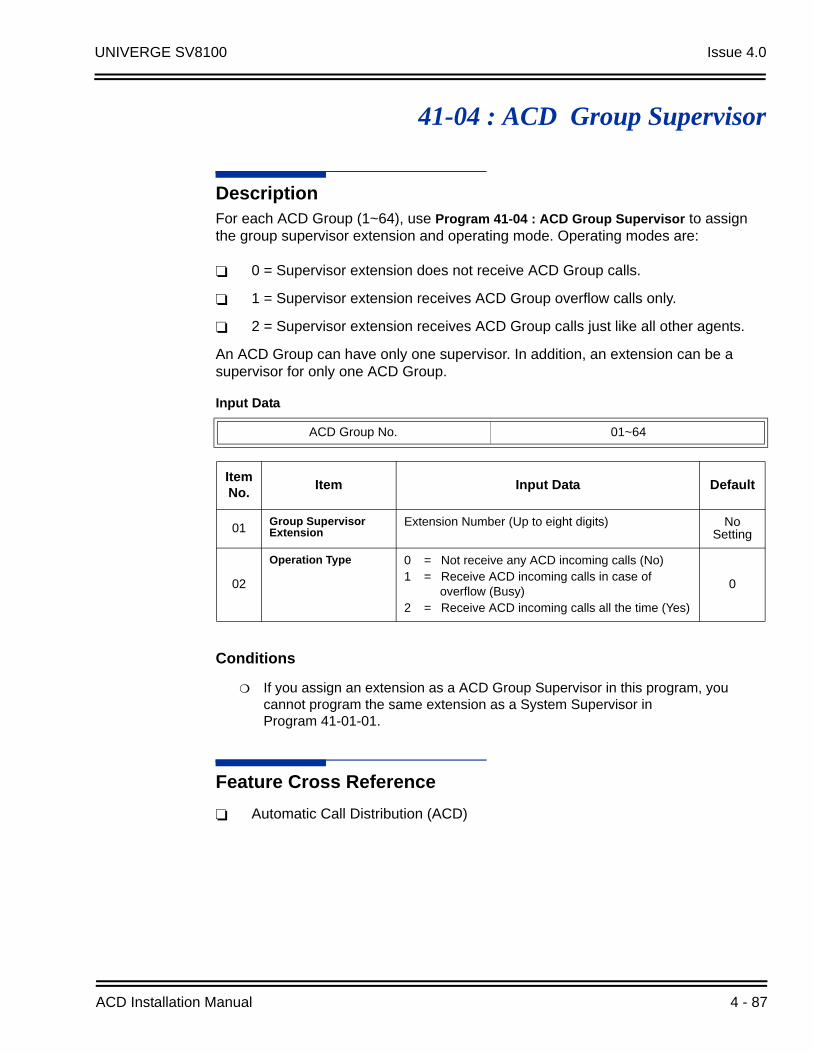
UNIVERGE SV8100 Issue 4.0
41-04 : ACD Group Supervisor
DescriptionFor each ACD Group (1~64), use Program 41-04 : ACD Group Supervisor to assign the group supervisor extension and operating mode. Operating modes are:
0 = Supervisor extension does not receive ACD Group calls.
1 = Supervisor extension receives ACD Group overflow calls only.
2 = Supervisor extension receives ACD Group calls just like all other agents.
An ACD Group can have only one supervisor. In addition, an extension can be a supervisor for only one ACD Group.
Conditions
If you assign an extension as a ACD Group Supervisor in this program, you cannot program the same extension as a System Supervisor in Program 41-01-01.
Feature Cross Reference
Automatic Call Distribution (ACD)
Input Data
ACD Group No. 01~64
Item No.
Item Input Data Default
01Group Supervisor Extension
Extension Number (Up to eight digits) No Setting
02
Operation Type 0 = Not receive any ACD incoming calls (No)1 = Receive ACD incoming calls in case of
overflow (Busy)2 = Receive ACD incoming calls all the time (Yes)
0
ACD Installation Manual 4 - 87

Issue 4.0 UNIVERGE SV8100
Telephone Programming Instructions
To enter data for Program 41-04 (ACD Group Supervisor):
1. Enter the programming mode.
2. 41 04
3. Enter the number of the item you want to program.
4. To select the ACD Group number to be programmed, press the FLASH or the volume or keys.
5. Enter data for the item you selected + Hold.
6. Enter data for the next item in the program.
- OR -
Press MSG once to enter a new item number.
- OR -
Press MSG until you exit that series programming section.
41-04-01 ACD Group1
GP_Supervisor
back select
41-04-nn ACD Groupnn
nnnnn
4 - 88

UNIVERGE SV8100 Issue 4.0
41-05 : ACD Agent Work Schedules
DescriptionUse Program 41-05 : ACD Agent Work Schedules to set up the Work Schedules for ACD Agents and Groups. For each ACD Work Schedule (1~4), designate the start and stop times for each of the eight Work Periods. After you set up the schedules in this program, assign them to days of the week in Program 41-07. (This is the same program used by the Trunk Work Schedules.)
ACD extensions can log in only during their work period. ACD extensions receive the following calls when they are logged in.
ACD Call on a TrunkWhen the incoming ring group is assigned in the operating time (Program 41-03 and 41-06)
ACD Pilot Number CallAny time – if ACD extensions are available
ConditionsNone
Feature Cross Reference
Automatic Call Distribution (ACD)
Input Data
ACD Work Schedule Time Pattern 1~4
Item No.
Work Period Mode
NumberStart Time End Time Default
01 1~8 0000~2359 0000~2359 (Start) 0000(End) 0000
ACD Installation Manual 4 - 89

Issue 4.0 UNIVERGE SV8100
Telephone Programming Instructions
To enter data for Program 41-05 (ACD Agent Work Schedules):
1. Enter the programming mode.
2. 41 05
3. Enter the number of the item you want to program.
4. To select the Time Pattern number to be programmed, press the FLASH or the volume or keys.
5. Enter data for the item you selected + Hold.
6. Enter data for the next item in the program.
- OR -
Press MSG once to enter a new item number.
- OR -
Press MSG until you exit that series programming section.
41-05-01 Time Pttn 1
Mode1 Start_Time=00:00
back select
41-05-nn Time Pttn n
nnnnn
4 - 90

UNIVERGE SV8100 Issue 4.0
41-06 : Trunk Work Schedules
DescriptionUse Program 41-06 : Trunk Work Schedules to set up the Work Schedules for trunks. For each Work Schedule (1~4), designate the start and stop times for each of the eight Work Periods. After you set up the schedules, assign them to days of the week in Program 41-07. (This is the same program used by the ACD Agent Work Schedules.)
ConditionsNone
Feature Cross Reference
Automatic Call Distribution (ACD)
Telephone Programming Instructions
To enter data for Program 41-06 (Trunk Work Schedules):
1. Enter the programming mode.
2. 41 06
3. Enter the number of the item you want to program.
Input Data
ACD Work Schedule Time Pattern Number 1~4
Item No.
Work Period Mode Number
Start Time End Time Default
01 1~8 0000~2359 0000~2359 (Start) 0000(End) 0000
41-06-01 Time Pttn 1
Mode1 Start_Time=00:00
back select
41-06-nn Time Pttn n
nnnnn
ACD Installation Manual 4 - 91

Issue 4.0 UNIVERGE SV8100
4. To select the Time Pattern number to be programmed, press the FLASH or the volume or keys.
5. Enter data for the item you selected + Hold.
6. Enter data for the next item in the program.
- OR -
Press MSG once to enter a new item number.
- OR -
Press MSG until you exit that series programming section.
4 - 92
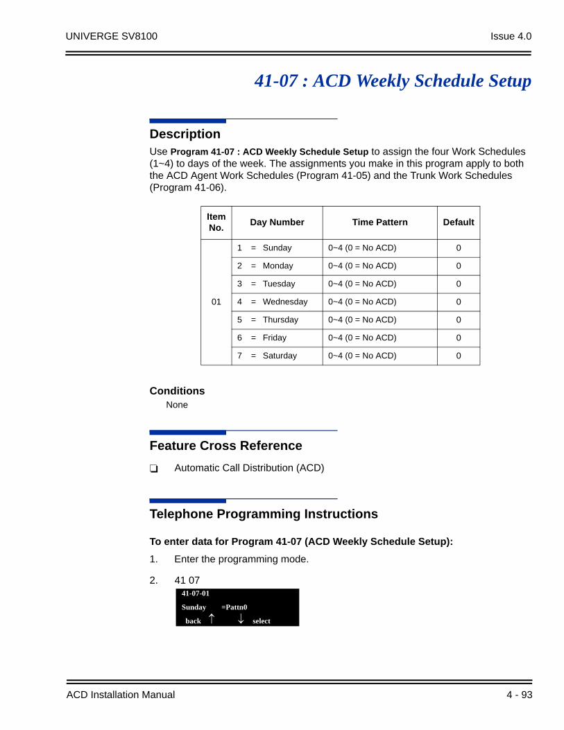
UNIVERGE SV8100 Issue 4.0
41-07 : ACD Weekly Schedule Setup
DescriptionUse Program 41-07 : ACD Weekly Schedule Setup to assign the four Work Schedules (1~4) to days of the week. The assignments you make in this program apply to both the ACD Agent Work Schedules (Program 41-05) and the Trunk Work Schedules (Program 41-06).
ConditionsNone
Feature Cross Reference
Automatic Call Distribution (ACD)
Telephone Programming Instructions
To enter data for Program 41-07 (ACD Weekly Schedule Setup):
1. Enter the programming mode.
2. 41 07
Item No.
Day Number Time Pattern Default
01
1 = Sunday 0~4 (0 = No ACD) 0
2 = Monday 0~4 (0 = No ACD) 0
3 = Tuesday 0~4 (0 = No ACD) 0
4 = Wednesday 0~4 (0 = No ACD) 0
5 = Thursday 0~4 (0 = No ACD) 0
6 = Friday 0~4 (0 = No ACD) 0
7 = Saturday 0~4 (0 = No ACD) 0
41-07-01
Sunday =Pattn0
back select
ACD Installation Manual 4 - 93
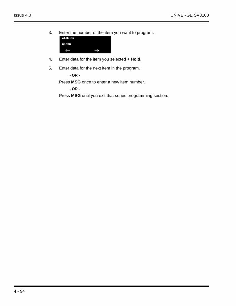
Issue 4.0 UNIVERGE SV8100
3. Enter the number of the item you want to program.
4. Enter data for the item you selected + Hold.
5. Enter data for the next item in the program.
- OR -
Press MSG once to enter a new item number.
- OR -
Press MSG until you exit that series programming section.
41-07-nn
nnnnn
4 - 94

UNIVERGE SV8100 Issue 4.0
41-08 : ACD Overflow Options
DescriptionFor each ACD Group (1~64), use Program 41-08 : ACD Overflow Options to assign the overflow mode (0~9), destination and announcement message types. Delay announcement functions are not available for ACD pilot number calls. Each ACD Group can have unique overflow options. The table below outlines the entry options.
Input Data
ACD Group No. 01~64
Item No.
Item Input Data Default
01
Overflow Operation Mode
0 = No overflow (None)1 = Overflow with No Announcement2 = No Overflow with First Announcement Only3 = No Overflow with First & Second
Announcements4 = Overflow with First Announcement Only5 = Overflow with First & Second Announcement6 = --- Not Used ---7 = --- Not Used ---8 = No Overflow with Second Announcement Only9 = Overflow with Second Announcement Only
0
02
ACD Overflow Destination
0 = No Setting1~64 = ACD Group65 = Overflow Table (Program 41-09)66 = Voice Mail Integration67 = System Speed (Program 41-08-05)68 = Incoming Ring Group (Program 41-08-06)
0
03Delay Announcement Source Type
0 = ACI1 = VRS2 = VM8000 InMail
0
04 ACD Overflow Transfer Time
0~64800 (sec) 30
05System Speed Dial Bin
0~1999(Used when 41-08-02 is set to 67)
1999
06Incoming Ring Group when Overflow
1~100(Used when 41-08-02 is set to 68) 1
ACD Installation Manual 4 - 95

Issue 4.0 UNIVERGE SV8100
Conditions
None
Feature Cross Reference
Automatic Call Distribution (ACD)
Telephone Programming Instructions
To enter data for Program 41-08 (ACD Overflow Options):
1. Enter the programming mode.
2. 41 08
3. Enter the number of the item you want to program.
4. To select the ACD Group number to be programmed, press the FLASH or the volume or keys.
5. Enter data for the item you selected + Hold.
6. Enter data for the next item in the program.
- OR -
Press MSG once to enter a new item number.
- OR -
Press MSG until you exit that series programming section.
41-08-01 ACD Group1
O-Flow_Mode 0:None |1
back select
41-08-nn ACD Groupnn
nnnnn
4 - 96
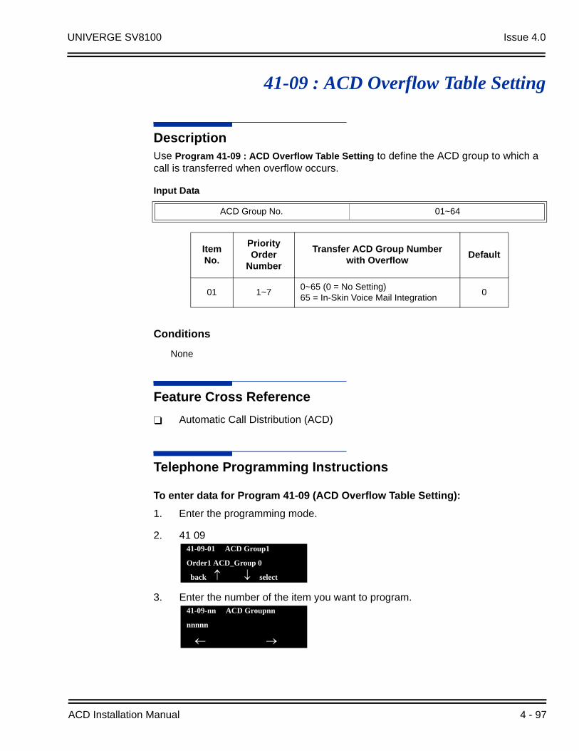
UNIVERGE SV8100 Issue 4.0
41-09 : ACD Overflow Table Setting
DescriptionUse Program 41-09 : ACD Overflow Table Setting to define the ACD group to which a call is transferred when overflow occurs.
Conditions
None
Feature Cross Reference
Automatic Call Distribution (ACD)
Telephone Programming Instructions
To enter data for Program 41-09 (ACD Overflow Table Setting):
1. Enter the programming mode.
2. 41 09
3. Enter the number of the item you want to program.
Input Data
ACD Group No. 01~64
Item No.
Priority Order
Number
Transfer ACD Group Numberwith Overflow
Default
01 1~70~65 (0 = No Setting)65 = In-Skin Voice Mail Integration
0
41-09-01 ACD Group1
Order1 ACD_Group 0
back select
41-09-nn ACD Groupnn
nnnnn
ACD Installation Manual 4 - 97

Issue 4.0 UNIVERGE SV8100
4. To select the ACD Group number to be programmed, press the FLASH or the volume or keys.
5. Enter data for the item you selected + Hold.
6. Enter data for the next item in the program.
- OR -
Press MSG once to enter a new item number.
- OR -
Press MSG until you exit that series programming section.
4 - 98

UNIVERGE SV8100 Issue 4.0
41-10 : ACI Delay Announcement
DescriptionUse Program 41-10 : ACI Delay Announcement to define the ACI port number to be used for the delay announcement.
This program is activated when the delay announcement source and options are assigned as ACI in Program 41-08-03.
ConditionsNone
Feature Cross Reference
Automatic Call Distribution (ACD)
Input Data
ACD Group No 01~64
Item No.
Item Input Data Default
011st Delay Announcement ACI Port Number 0~96
0 = No Setting0
022nd Delay Announcement ACI Port Number 0~96
0 = No Setting0
031st Delay Announcement Connection TimerSet the time before the 1st Delay Announcement is played.
0~64800 (sec)4
042nd Delay Announcement Connection TimerSet the time the 1st Delay Announcement plays before the 2nd Delay Announcement starts to play.
0~64800 (sec)60
05
2nd Delay Announcement Sending DurationSet the timer for how long the 2nd Delay Announcement plays. After this timer expires, the call disconnects. To keep the call in queue, set this timer to 0.
0~64800 (sec)
0
ACD Installation Manual 4 - 99

Issue 4.0 UNIVERGE SV8100
THIS PAGE INTENTIONALLY LEFT BLANK
4 - 100

UNIVERGE SV8100 Issue 4.0
41-11 : VRS Delay Announcement
DescriptionUse Program 41-11 : VRS Delay Announcement to assign the VRS message number to be used as the message source for the 1st and 2nd Delay Announcement Messages. Refer to Program 41-08 for more on setting up the ACD overflow options.
This program is activated when the delay announcement source and options are assigned as VRS in Program 41-08-03.
Input Data
ACD Group No. 01~64
Item No.
Item Input Data Default
01Delay Message Start TimerInput the time before the 1st Delay Message Starts.
0~64800 (sec)0
021st Delay Message NumberInput the VRS Message to be played as the 1st Delay Message.
0~1010 = No Message101 = Fixed Message
0
03
1st Delay Message Sending CountInput the number of times the 1st Delay Message is sent. If set to 0, the message is not played.
0~255
0
042nd Delay Message NumberInput the VRS Message to be played as the 2nd Delay Message.
0~1010 = No Message101 = Fixed Message
0
05
2nd Waiting Message Sending CountInput the number of times the 2nd Delay Message is sent. If set to 0, the message is not played.
0~255
0
06Tone Kind at Message IntervalInput what is heard between the Delay messages.
0 = Ring Back Tone1 = MOH Tone2 = BGM Source
0
07
ACD Forced Disconnect Time after the 2nd Delay MessageSet the time, after the last 2nd Delay Message is played, before the call is disconnected.
0~64800 (sec)(0 = No Disconnect)
60
ACD Installation Manual 4 - 101

Issue 4.0 UNIVERGE SV8100
ConditionsNone
Feature Cross Reference
Automatic Call Distribution (ACD)
Telephone Programming Instructions
To enter data for Program 41-11 (VRS Delay Announcement):
1. Enter the programming mode.
2. 41 11
3. Enter the number of the item you want to program.
4. To select the ACD Group number to be programmed, press the FLASH or the volume or keys.
5. Enter data for the item you selected + Hold.
6. Enter data for the next item in the program.
- OR -
Press MSG once to enter a new item number.
- OR -
Press MSG until you exit that series programming section.
08
Queue Depth AnnouncementInput when the Queue Depth Announcement will be played.
0 = Disable1 = After 1st (1st)2 = After 2nd (2nd)3 = After 1st and 2nd
(1st and 2nd)
0
41-11-01 ACD Group1
Delay_Msg_Strt0 Sec.
back select
41-11-nn ACD Groupnn
nnnnn
4 - 102

UNIVERGE SV8100 Issue 4.0
41-12 : Night Announcement Setup
DescriptionUse Program 41-12 : Night Announcement Setup to define the night announce voice resource and sending time for each ACD group. Night announcement availability depends on the setting in Program 41-03-02. The night announcement function is not available for ACD pilot number calls.
Conditions
The night announcement function is not available for ACD pilot number call.
Feature Cross Reference
Automatic Call Distribution (ACD)
Telephone Programming Instructions
To enter data for Program 41-12 (Night Announcement Setup):
1. Enter the programming mode.
Input Data
ACD Group Number 01~64
Item No.
Item Input Data Default
01Night Announcement Source Type 0 = ACI
1 = VRS0
02Night Announcement ACI Port NumberOnly used when Program 41-12-01 is set to 0.
0~960 = No Setting 0
03ACD Night Announce Sending TimeOnly used when Program 41-12-01 is set to 0.
0~64800 (sec)30
ACD Installation Manual 4 - 103

Issue 4.0 UNIVERGE SV8100
2. 41 12
1. Enter the number of the item you want to program.
2. To select the ACD Group number to be programmed, press the FLASH or the volume or keys.
3. Enter data for the item you selected + Hold.
4. Enter data for the next item in the program.
- OR -
Press MSG once to enter a new item number.
- OR -
Press MSG until you exit that series programming section.
41-12-01 ACD Group1
NT Source 0:ACI
back select
41-12-nn ACD Groupnn
nnnnn
4 - 104

UNIVERGE SV8100 Issue 4.0
41-13 : VRS Message Number for Night Announcement
DescriptionUse Program 41-13 : VRS Message Number for Night Announcement to define the VRS message number to be used as the night announcement. This program is activated when the night announcement source is assigned as VRS in Program 41-12.
ConditionsNone
Feature Cross Reference
Automatic Call Distribution (ACD)
Telephone Programming Instructions
To enter data for Program 41-13 (VRS Night Announcement):
1. Enter the programming mode.
2. 41 13
Input Data
ACD Group No. 01~64
Item No.
Item Input Data Default
01
VRS Message NumberInput the VRS Message to be used for the Night Announcement.
0~1000 = No Message 0
02Tone Kind at Message IntervalInput what is heard between the Night Announcements.
0 = Ring Back Tone1 = MOH Tone2 = BGM Source
0
41-13-01 ACD Group1
VRS Msg No 0
back select
ACD Installation Manual 4 - 105

Issue 4.0 UNIVERGE SV8100
3. Enter the number of the item you want to program.
4. To select the ACD Group number to be programmed, press the FLASH or the volume or keys.
5. Enter data for the item you selected + Hold.
6. Enter data for the next item in the program.
- OR -
Press MSG once to enter a new item number.
- OR -
Press MSG until you exit that series programming section.
41-13-nn ACD Groupnn
nnnnn
4 - 106
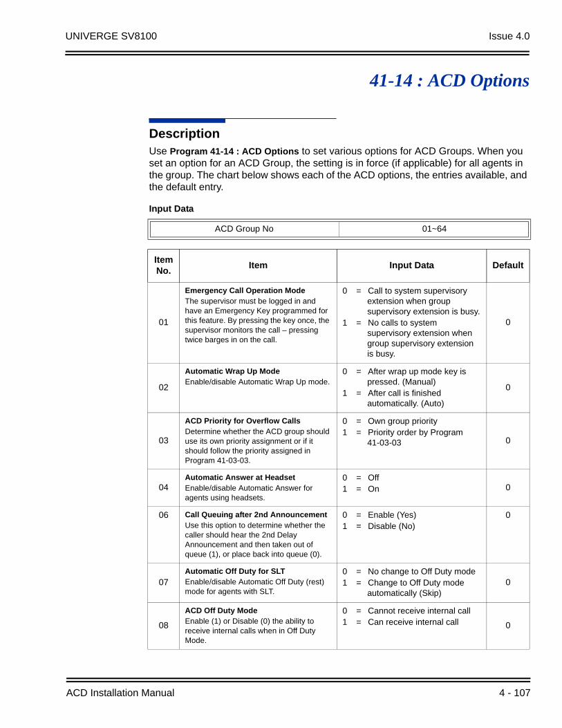
UNIVERGE SV8100 Issue 4.0
41-14 : ACD Options
DescriptionUse Program 41-14 : ACD Options to set various options for ACD Groups. When you set an option for an ACD Group, the setting is in force (if applicable) for all agents in the group. The chart below shows each of the ACD options, the entries available, and the default entry.
Input Data
ACD Group No 01~64
Item No.
Item Input Data Default
01
Emergency Call Operation ModeThe supervisor must be logged in and have an Emergency Key programmed for this feature. By pressing the key once, the supervisor monitors the call – pressing twice barges in on the call.
0 = Call to system supervisory extension when group supervisory extension is busy.
1 = No calls to system supervisory extension when group supervisory extension is busy.
0
02
Automatic Wrap Up ModeEnable/disable Automatic Wrap Up mode.
0 = After wrap up mode key is pressed. (Manual)
1 = After call is finished automatically. (Auto)
0
03
ACD Priority for Overflow CallsDetermine whether the ACD group should use its own priority assignment or if it should follow the priority assigned in Program 41-03-03.
0 = Own group priority1 = Priority order by Program
41-03-03 0
04Automatic Answer at HeadsetEnable/disable Automatic Answer for agents using headsets.
0 = Off1 = On 0
06 Call Queuing after 2nd Announcement Use this option to determine whether the caller should hear the 2nd Delay Announcement and then taken out of queue (1), or place back into queue (0).
0 = Enable (Yes)1 = Disable (No)
0
07Automatic Off Duty for SLTEnable/disable Automatic Off Duty (rest) mode for agents with SLT.
0 = No change to Off Duty mode 1 = Change to Off Duty mode
automatically (Skip)0
08
ACD Off Duty ModeEnable (1) or Disable (0) the ability to receive internal calls when in Off Duty Mode.
0 = Cannot receive internal call1 = Can receive internal call 0
ACD Installation Manual 4 - 107
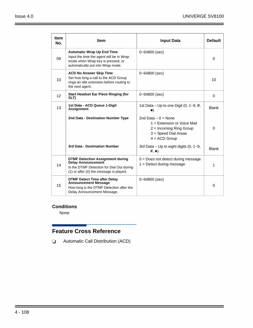
Issue 4.0 UNIVERGE SV8100
ConditionsNone
Feature Cross Reference
Automatic Call Distribution (ACD)
09
Automatic Wrap Up End TimeInput the time the agent will be in Wrap mode when Wrap key is pressed, or automatically put into Wrap mode.
0~64800 (sec)
0
10
ACD No Answer Skip TimeSet how long a call to the ACD Group rings an idle extension before routing to the next agent.
0~64800 (sec)
10
12 Start Headset Ear Piece Ringing (for SLT)
0~64800 (sec) 0
131st Data - ACD Queue 1-Digit Assignment
1st Data – Up to one Digit (0, 1~9, #, )
Blank
2nd Data - Destination Number Type 2nd Data – 0 = None 1 = Extension or Voice Mail 2 = Incoming Ring Group 3 = Speed Dial Areas 4 = ACD Group
0
3rd Data - Destination Number 3rd Data – Up to eight digits (0, 1~9, #, )
Blank
14
DTMF Detection Assignment during Delay AnnouncementIs the DTMF Detection for Dial Out during (1) or after (0) the message is played.
0 = Does not detect during message1 = Detect during message 1
15
DTMF Detect Time after Delay Announcement MessageHow long is the DTMF Detection after the Delay Announcement Message.
0~64800 (sec)
0
Item No.
Item Input Data Default
4 - 108

UNIVERGE SV8100 Issue 4.0
Telephone Programming Instructions
To enter data for Program 41-14 (ACD Options):
1. Enter the programming mode.
2. 41 14
3. Enter the number of the item you want to program.
4. To select the ACD Group number to be programmed, press the FLASH or the volume or keys.
5. Enter data for the item you selected + Hold.
6. Enter data for the next item in the program.
- OR -
Press MSG once to enter a new item number.
- OR -
Press MSG until you exit that series programming section.
41-14-01 ACD Group1
EMG Call Mode 0:On
back select
41-14-nn ACD Groupnn
nnnnn
ACD Installation Manual 4 - 109

Issue 4.0 UNIVERGE SV8100
THIS PAGE INTENTIONALLY LEFT BLANK
4 - 110

UNIVERGE SV8100 Issue 4.0
41-15 : ACD Queue Alarm Information
DescriptionUse Program 41-15 : ACD Queue Alarm Information to assign the options for Audible Indication for Log Out / Off Duty mode for each ACD group.
These program settings provide an alarm to the agents, but no Queue Status Display is indicated. Do not use these programs if the alarm options are defined in Program 41-20-01 through 41-20-05.
ConditionsNone
Feature Available in Program 41-15 Available in Program 41-20
Queue Status Display --- Yes
Queue Status Display Time
--- Yes
Alarm Yes Yes
Alarm Send TimeProgram 41-15-02 determines the length/interval of the alarm.
Yes
Interval Time of Queue Status Display
Yes
Class of Service --- Yes
Timing of Alarm and Display Queue Status
Alarm triggered after the number of calls in Program 41-15-01 is exceeded.
Alarm triggered after the number of calls in Program 41-20-01 is exceeded. Then follows Program 41-20-03 timing for displaying status.
Input Data
ACD Group No. 01~64
Item No.
Item Input Data Default
01Number of Calls in ACD Queue to Activate Alarm Information
0~2000 = No Alarm 0
02Interval time of Alarm InformationInput the alarm sound time.
0~64800 (sec) 0
ACD Installation Manual 4 - 111

Issue 4.0 UNIVERGE SV8100
Feature Cross Reference
Automatic Call Distribution (ACD)
Telephone Programming Instructions
To enter data for Program 41-15 (ACD Queue Alarm Information):
1. Enter the programming mode.
2. 41 15
3. Enter the number of the item you want to program.
4. To select the ACD Group number to be programmed, press the FLASH or the volume or keys.
5. Enter data for the item you selected + Hold.
6. Enter data for the next item in the program.
- OR -
Press MSG once to enter a new item number.
- OR -
Press MSG until you exit that series programming section.
41-15-01 ACD Group1
ACD Alarm 0
back select
41-15-nn ACD Groupnn
nnnnn
4 - 112
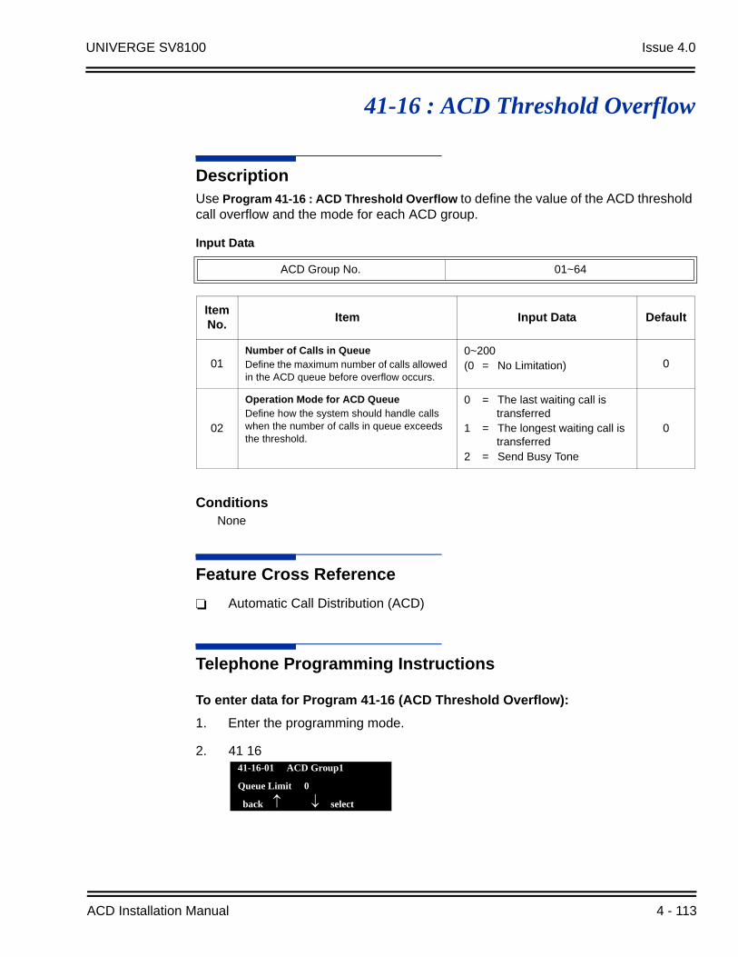
UNIVERGE SV8100 Issue 4.0
41-16 : ACD Threshold Overflow
DescriptionUse Program 41-16 : ACD Threshold Overflow to define the value of the ACD threshold call overflow and the mode for each ACD group.
ConditionsNone
Feature Cross Reference
Automatic Call Distribution (ACD)
Telephone Programming Instructions
To enter data for Program 41-16 (ACD Threshold Overflow):
1. Enter the programming mode.
2. 41 16
Input Data
ACD Group No. 01~64
Item No.
Item Input Data Default
01Number of Calls in QueueDefine the maximum number of calls allowed in the ACD queue before overflow occurs.
0~200(0 = No Limitation) 0
02
Operation Mode for ACD QueueDefine how the system should handle calls when the number of calls in queue exceeds the threshold.
0 = The last waiting call is transferred
1 = The longest waiting call is transferred
2 = Send Busy Tone
0
41-16-01 ACD Group1
Queue Limit 0
back select
ACD Installation Manual 4 - 113

Issue 4.0 UNIVERGE SV8100
3. Enter the number of the item you want to program.
4. To select the ACD Group number to be programmed, press the FLASH or the volume or keys.
5. Enter data for the item you selected + Hold.
6. Enter data for the next item in the program.
- OR -
Press MSG once to enter a new item number.
- OR -
Press MSG until you exit that series programming section.
41-16-nn ACD Groupnn
nnnnn
4 - 114
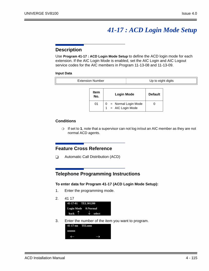
UNIVERGE SV8100 Issue 4.0
41-17 : ACD Login Mode Setup
DescriptionUse Program 41-17 : ACD Login Mode Setup to define the ACD login mode for each extension. If the AIC Login Mode is enabled, set the AIC Login and AIC Logout service codes for the AIC members in Program 11-13-08 and 11-13-09.
Conditions
If set to 1, note that a supervisor can not log in/out an AIC member as they are not normal ACD agents.
Feature Cross Reference
Automatic Call Distribution (ACD)
Telephone Programming Instructions
To enter data for Program 41-17 (ACD Login Mode Setup):
1. Enter the programming mode.
2. 41 17
3. Enter the number of the item you want to program.
Input Data
Extension Number Up to eight digits
Item No.
Login Mode Default
01 0 = Normal Login Mode1 = AIC Login Mode
0
41-17-01 TEL301200
Login Mode 0:Normal
back select
41-17-nn TELnnn
nnnnn
ACD Installation Manual 4 - 115

Issue 4.0 UNIVERGE SV8100
4. To select the telephone number to be programmed, press the FLASH or the volume or keys.
5. Enter data for the item you selected + Hold.
6. Enter data for the next item in the program.
- OR -
Press MSG once to enter a new item number.
- OR -
Press MSG until you exit that series programming section.
4 - 116

UNIVERGE SV8100 Issue 4.0
41-18 : ACD Agent Identity Code Setup
DescriptionUse Program 41-18 : ACD Agent Identity Code Setup to define the ACD Agent Identity Code Table.
ConditionsNone
Feature Cross ReferenceNone
Input Data
AIC Table No. 001~512
Item No.
Item Input Data Default
01 ACD Agent Identity Code Up to four digits No Setting
02Default ACD Group Number 0~64
0 = No Setting 0
03ACD Group Number in Mode 1 0~64
0 = No Setting 0
04ACD Group Number in Mode 2 0~64
0 = No Setting 0
05ACD Group Number in Mode 3 0~64
0 = No Setting 0
06ACD Group Number in Mode 4 0~64
0 = No Setting 0
07ACD Group Number in Mode 5 0~64
0 = No Setting 0
08ACD Group Number in Mode 6 0~64
0 = No Setting 0
09ACD Group Number in Mode 7 0~64
0 = No Setting 0
10ACD Group Number in Mode 8 0~64
0 = No Setting 0
ACD Installation Manual 4 - 117

Issue 4.0 UNIVERGE SV8100
Telephone Programming Instructions
To enter data for Program 41-18 (ACD Agent Identity Code Setup):
1. Enter the programming mode.
2. 41 18
3. Enter the number of the item you want to program.
4. To select the Agent Identity Code (AIC) number to be programmed, press the FLASH or the volume or keys.
5. Enter data for the item you selected + Hold.
6. Enter data for the next item in the program.
- OR -
Press MSG once to enter a new item number.
- OR -
Press MSG until you exit that series programming section.
41-18-01 AIC TBL 1
AIC Code
back select
41-18-nn AIC TBL nnn
nnnnn
4 - 118

UNIVERGE SV8100 Issue 4.0
41-19 : ACD Voice Mail Delay Announcement
DescriptionUse Program 41-19 : ACD Voice Mail Delay Announcement to assign In-Mail Master Mailboxes (PRG 47-03) as ACD Delay “Announcement” Mailboxes.
Input Data
ACD Group Number 1 ~ 64
Item No.
Item Input Data Default
01Delay Message Start TimerDetermines how long the system waits before playing the Delay Message.
0 ~ 64800 (sec)0
02
Mailbox Number for 1st Announcement MessageAssigns the Voice Mail ACD Announcement Mailbox as the message source for the 1st Announcement Message.
Dial(up to eight digits) No
Setting
03
1st Delay Message Sending CountDetermines the 1st Delay Message Sending Count. This entry must be set to 1 or higher in order for the message to play.
0 = No message is played.
1 ~ 2550
04
Mailbox Number for 2nd Announcement MessageAssigns the Voice Mail ACD Announcement Mailboxes as the message source for the 2nd Announcement Message.
Dial(up to eight digits) No
Setting
05
2nd Delay Message Sending CountDetermines the 2nd Delay Message Sending Count. This entry must be set to 1 or higher in order for the message to play.
0 = No message is played.
1 ~ 2550
06
Wait Tone Type at Message IntervalDetermines what the caller will hear between the messages.
0 = Ring Back Tone
1 = Music On Hold Tone
2 = Background Music Source
0
07
ACD Forced Disconnect Time after 2nd AnnouncementAssigns how long the system should wait after the end of the ACD Delay Message before disconnecting.
0 ~ 64800 (sec)
0
08Delay Message Interval TimeSets the timer for the interval between the Delay Messages.
0 ~ 64800 (sec) 20
ACD Installation Manual 4 - 119

Issue 4.0 UNIVERGE SV8100
ConditionsNone
Feature Cross ReferenceNone
4 - 120

UNIVERGE SV8100 Issue 4.0
41-21 : ACD Login ID Setup
DescriptionUse Program 41-21 : ACD Login ID Setup to assign the Login ID code to Skill Table used for ACD Skill Based Routing.
Conditions
None
Feature Cross Reference
Automatic Call Distribution (ACD)
Input Data
ACD Group No. 01~64
Item No. Item Input Data Default
01Login ID Code
Input the Login ID(s) to be used.
Up to 20 digits No Setting
02Skill Table Number
Input the Skill Table number to be used for each Login ID.
0, 1~5120
ACD Installation Manual 4 - 121

Issue 4.0 UNIVERGE SV8100
41-22 : ACD Skill Base Routing Setup
DescriptionUse Program 41-22 : ACD Skill Base Routing Setup to assign if the ACD Group can use or not use Skill Based Routing.
Conditions
None
Feature Cross Reference
Automatic Call Distribution (ACD)
Input Data
ACD Group No. 01~64
Item No. Item Input Data Default
01Skill Base Routing
This option determines if the Skill Based Routing is Used (1), or Not Used (0).
0 = Off1 = On 0
4 - 122
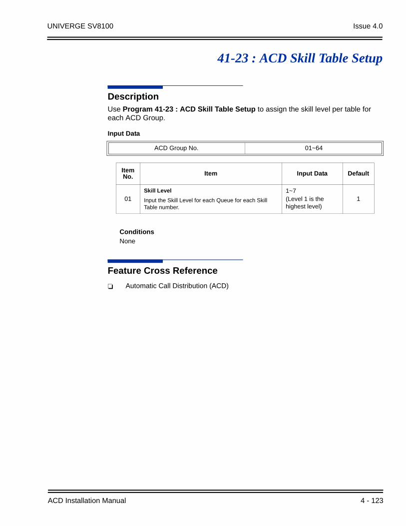
UNIVERGE SV8100 Issue 4.0
41-23 : ACD Skill Table Setup
DescriptionUse Program 41-23 : ACD Skill Table Setup to assign the skill level per table for each ACD Group.
Conditions
None
Feature Cross Reference
Automatic Call Distribution (ACD)
Input Data
ACD Group No. 01~64
Item No. Item Input Data Default
01Skill Level
Input the Skill Level for each Queue for each Skill Table number.
1~7 (Level 1 is the highest level)
1
ACD Installation Manual 4 - 123
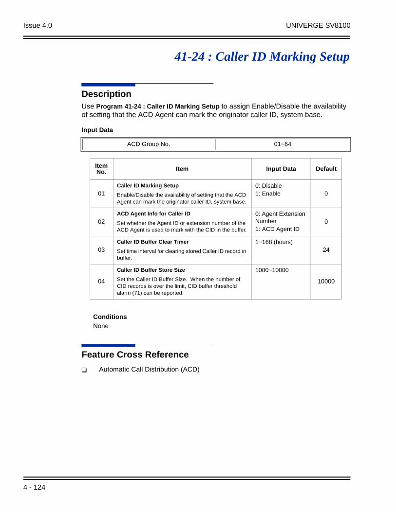
Issue 4.0 UNIVERGE SV8100
41-24 : Caller ID Marking Setup
DescriptionUse Program 41-24 : Caller ID Marking Setup to assign Enable/Disable the availability of setting that the ACD Agent can mark the originator caller ID, system base.
Conditions
None
Feature Cross Reference
Automatic Call Distribution (ACD)
Input Data
ACD Group No. 01~64
Item No. Item Input Data Default
01Caller ID Marking Setup
Enable/Disable the availability of setting that the ACD Agent can mark the originator caller ID, system base.
0: Disable1: Enable 0
02ACD Agent Info for Caller ID
Set whether the Agent ID or extension number of the ACD Agent is used to mark with the CID in the buffer.
0: Agent Extension Number1: ACD Agent ID
0
03Caller ID Buffer Clear Timer
Set time interval for clearing stored Caller ID record in buffer.
1~168 (hours)24
04
Caller ID Buffer Store Size
Set the Caller ID Buffer Size. When the number of CID records is over the limit, CID buffer threshold alarm (71) can be reported.
1000~10000
10000
4 - 124

UNIVERGE SV8100 Issue 4.0
47-03 : UNIVERGE SV8100 InMail Master Mailbox Options
DescriptionUse 47-03 : SV8100 InMail Master Mailbox Options to set up the 32 Group Mailboxes (01~32). A Group Mailbox is used for Department Group overflow and can be a Subscriber or Call Routing.
ConditionsNone
Feature Cross ReferenceNone
Item No. Item Input Data Default
02
Mailbox Number(Mailbox Number)
The Group Mailbox Number is the same as the Department Group master (pilot) number. Use this option to select the Department Group master (pilot) number associated with the Group Mailbox you are programming.
Digits (eight maximum, using 0~9)No Setting (entered by pressing Hold)
No Setting
03
Mailbox Type(Mailbox Type)
Use this option to set the Group Mailbox type. There are three types of SV8100 InMail mailboxes: None (0), Subscriber (1) and Routing (2).
0 = None1 = Subscriber2 = Routing 1
Routing Mailbox NumberIf 47-03-03: Group Mailbox Type is set to 2 (Routing), use this option to specify the Routing Mailbox InMail uses for the Group Mailbox.
1~32
1
ACD Installation Manual 4 - 125

Issue 4.0 UNIVERGE SV8100
THIS PAGE INTENTIONALLY LEFT BLANK
4 - 126
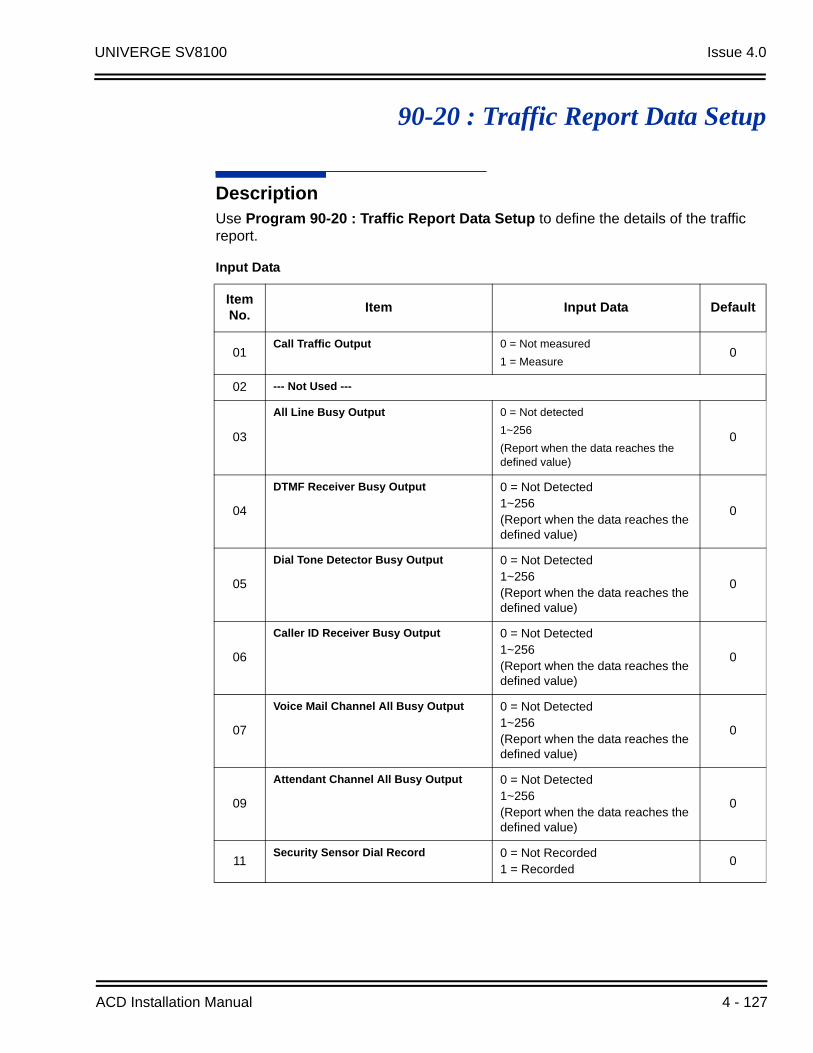
UNIVERGE SV8100 Issue 4.0
90-20 : Traffic Report Data Setup
DescriptionUse Program 90-20 : Traffic Report Data Setup to define the details of the traffic report.
Input Data
Item No.
Item Input Data Default
01Call Traffic Output 0 = Not measured
1 = Measure0
02 --- Not Used ---
03
All Line Busy Output 0 = Not detected
1~256
(Report when the data reaches the defined value)
0
04
DTMF Receiver Busy Output 0 = Not Detected1~256(Report when the data reaches the defined value)
0
05
Dial Tone Detector Busy Output 0 = Not Detected1~256(Report when the data reaches the defined value)
0
06
Caller ID Receiver Busy Output 0 = Not Detected1~256(Report when the data reaches the defined value)
0
07
Voice Mail Channel All Busy Output 0 = Not Detected1~256(Report when the data reaches the defined value)
0
09
Attendant Channel All Busy Output 0 = Not Detected1~256(Report when the data reaches the defined value)
0
11Security Sensor Dial Record 0 = Not Recorded
1 = Recorded0
ACD Installation Manual 4 - 127
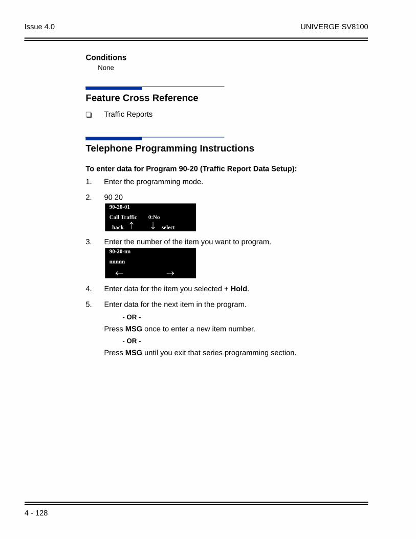
Issue 4.0 UNIVERGE SV8100
ConditionsNone
Feature Cross Reference
Traffic Reports
Telephone Programming Instructions
To enter data for Program 90-20 (Traffic Report Data Setup):
1. Enter the programming mode.
2. 90 20
3. Enter the number of the item you want to program.
4. Enter data for the item you selected + Hold.
5. Enter data for the next item in the program.
- OR -
Press MSG once to enter a new item number.
- OR -
Press MSG until you exit that series programming section.
90-20-01
Call Traffic 0:No
back select
90-20-nn
nnnnn
4 - 128
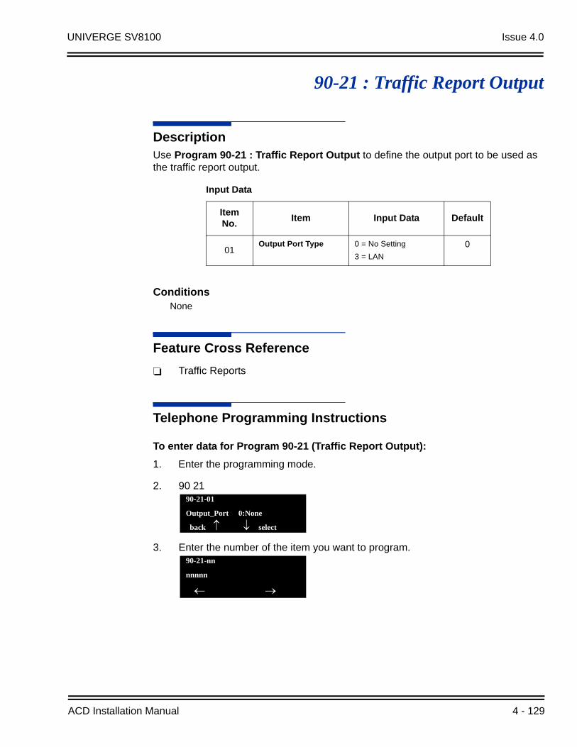
UNIVERGE SV8100 Issue 4.0
90-21 : Traffic Report Output
DescriptionUse Program 90-21 : Traffic Report Output to define the output port to be used as the traffic report output.
ConditionsNone
Feature Cross Reference
Traffic Reports
Telephone Programming Instructions
To enter data for Program 90-21 (Traffic Report Output):
1. Enter the programming mode.
2. 90 21
3. Enter the number of the item you want to program.
Input Data
Item No.
Item Input Data Default
01Output Port Type 0 = No Setting
3 = LAN
0
90-21-01
Output_Port 0:None
back select
90-21-nn
nnnnn
ACD Installation Manual 4 - 129
Issue 4.0 UNIVERGE SV8100
4. Enter data for the item you selected + Hold.
5. Enter data for the next item in the program.
- OR -
Press MSG once to enter a new item number.
- OR -
Press MSG until you exit that series programming section.
4 - 130


AUTOMATIC CALL DISTRIBUTION (ACD) INSTALLATION MANUAL
NEC Corporation of America
Issue 4.0


