+ All Categories
Home > Documents > Automatic Interface Synthesis based on the … Interface Synthesis based on the Classification of...

Automatic Interface Synthesis based on the … Interface Synthesis based on the Classification of...

Date post: 22-May-2018
Category:
Upload: phamdat
View: 215 times
Download: 0 times
Share this document with a friend
26
Automatic Interface Synthesis based on the Classification of Interface Protocols of IPs ChangRyul Yun 1 , DongSu Kang 2 , YoungHwan Bae 3 , HanJin Cho 3 , KyoungSon Jhang 2 1 Agency for Defense Development, KOREA 2 Dept. of Computer Engineering, ChungNam National University, KOREA 3 Multimedia SoC Design Team, ETRI, KOREA
Transcript

Automatic Interface Synthesis based on the Classification of Interface

Protocols of IPs

ChangRyul Yun1, DongSu Kang2, YoungHwan Bae3, HanJin Cho3, KyoungSon Jhang2

1Agency for Defense Development, KOREA2Dept. of Computer Engineering, ChungNam National University, KOREA

3Multimedia SoC Design Team, ETRI, KOREA

2

Outline• Introduction & Motivation

– Interface circuit structures• Proposed Interface Synthesis Method

– Interface Synthesis Flow– SIMPLE (Simplified Interface Protocol Description

Language)– Classification of Interface Protocols of IPs– The Structures of interface Circuits– Interface Synthesis Algorithm

• Experiments• Conclusion

3

Introduction

• IP-based Design Methodology in SoC– A methodology to respond to the demands of high

performance, complex functionality, short time-to-market

– One of key issues: The difficulty of IPs integration• IPs use various interface protocols

– Interface circuits between IPs are necessary.• Interface circuits

– Time-consuming and error-prone task– Automatic interface circuit generation method is

necessary.

4

Introduction• Automatic Interface Synthesis Flow based on

interface FSMs

IP(Master)

IP(Slave)

Interfacecircuits

Protocol SpecificationProtocol Specification Protocol SpecificationProtocol Specification

InterfaceFSM

InterfaceFSM

InterfaceFSM

InterfaceFSM

The Subset of Product

FSM

The Subset of Product

FSMMatching

Information

5

Motivation

IP(Master)

IP(Slave)

Interfacecircuits

Protocol SpecificationProtocol Specification Protocol SpecificationProtocol Specification

InterfaceFSM

InterfaceFSM

InterfaceFSM

InterfaceFSM

The Subset of Product

FSM

The Subset of Product

FSM

A synthesis algorithm should consider various characteristics on generation of interface circuits.

Flexible and highly appropriate structure depending on IP characteristics and system level requirements.

Easy and efficient interface protocol description method of IPs.
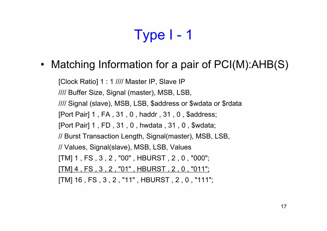
MatchingInformation

User constraints

6

Motivation

• The various characteristics of interface protocols of IPs– Address and data transfer characteristics

• The number of addresses on burst • Shared signal or different signals for an address and data

– No Address– Different clock frequencies– Different data widths

• These differences should be considered on an interface synthesis algorithm.

7

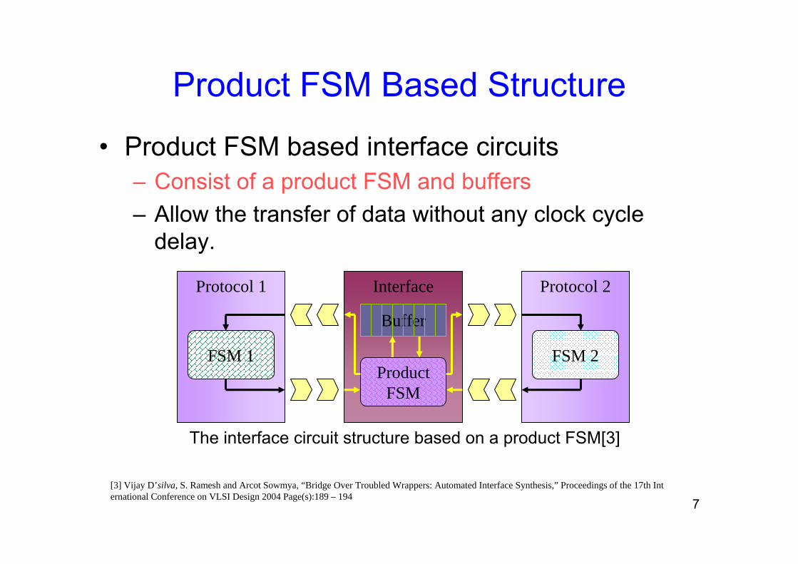
Product FSM Based Structure

• Product FSM based interface circuits– Consist of a product FSM and buffers– Allow the transfer of data without any clock cycle

delay.

Protocol 1

FSM 1

Interface Protocol 2

FSM 2Product

FSM

Buffer

The interface circuit structure based on a product FSM[3]

[3] Vijay D’silva, S. Ramesh and Arcot Sowmya, “Bridge Over Troubled Wrappers: Automated Interface Synthesis,” Proceedings of the 17th International Conference on VLSI Design 2004 Page(s):189 – 194

8

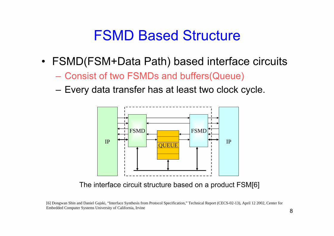
FSMD Based Structure

• FSMD(FSM+Data Path) based interface circuits– Consist of two FSMDs and buffers(Queue)– Every data transfer has at least two clock cycle.

IP IP

FSMD FSMD

QUEUEQUEUE

The interface circuit structure based on a product FSM[6]

[6] Dongwan Shin and Daniel Gajski, “Interface Synthesis from Protocol Specification,” Technical Report (CECS-02-13), April 12 2002, Center for Embedded Computer Systems University of California, Irvine

9

IPC Based Structure

• IPC (Interface Protocol Component) [10]– Protocol Convert

• From transaction level to cycle level vice versa.

– No internal buffers

COREMasterIPC

CORETransaction code

Transaction arguments

Interface ports with IP

Interface ports with IP

SlaveIPC

Transaction code

Transaction arguments

Execute transaction by transaction code Recognize transaction by signals

[10] ChangRyul Yun, KyoungSon Jhang, “An Interface Protocol Component Modeling Language,” Proceedings of the 15th ASIC/SOC Conference, Sept. 2002, Page(s): 456-460

10

Proposed Interface Synthesis Flow

ProtocolDescription

(Master)

ProtocolDescription

(Master)

ProtocolDescription

(Slave)

ProtocolDescription

(Slave)

Parsing & Build

interfaceFSMs

InterfaceFSM

(Master)

InterfaceFSM

(Master)

InterfaceFSM

(Slave)

InterfaceFSM

(Slave)

Protocol

Analysis

Protocol

Analysis

Type IInterfaceCircuits

Type IInterfaceCircuits

MatchingInformationMatching

InformationBuild

a ProductFSM

Builda Product

FSM

BuildIPCs

BuildIPCs

Type IIInterfaceCircuits

Type IIInterfaceCircuits

• Classify Interface Protocols• Select a synthesis algorithm for interface structuredepending on analysis results or user constraints

11

Interface FSM

• Protocol Description Methods– Waveform or timing diagram– Formal language

• SIMPLE (Proposed Description Method)– Simplified Interface Protocol Description Language[10]– Interface Protocol: Transfers + Parameters

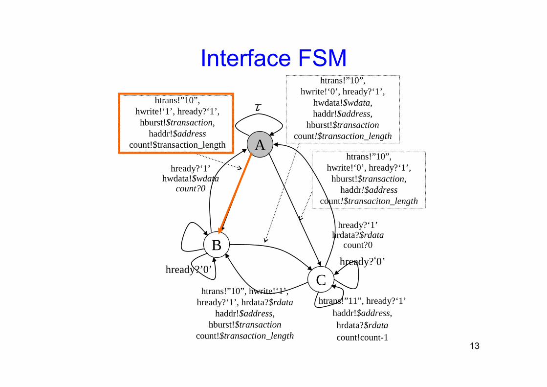
• Transfer: the behavior of ports on a cycle• Parameter

– Address, data, transaction information and etc.– Used to match the different feature of IPs

[7] ChangRyul Yun, YoungHwan Bae, HanJin Cho, KyoungSon Jhang, “Automatic Synthesis of Interface Circuits from Simplified IP Interface Protocols,” Proceedings of the Eleventh Asia-Pacific Computer Systems Architecture Conference (ACSAC 2006), September 6-8th, Page(s):581-587

12

Interface FSM• SIMPLEDefine $new_transaction, $write; /* ⑤, ⑥ */Interface AHB_Master {

in bit HREADY; /* Ports List */:

initial A; /* ① Initial State */ AMBA_MASTER: behavior {

int count; // User Defined Variable A: if ( $new_transaction == 1 ) /* ⑤ */ {

HTRANS = "10"; // NONSEQHADDR = $address; /* ④ */HBURST = $transaction; /* ② */count = $transaction_length; /* ③ */if ($write == '1') /* ⑥ */ {

HWRITE = '1';if ( HREADY == '1')

goto B; :

} else

goto A;}

• Reserved Parameter②: transaction type③: transaction length④: address

• User Defined Parameter⑤, ⑥

AHB Master interface ProtocolA part of the description

13

A

B

C

htrans!”10”,hwrite!‘1’, hready?‘1’, hburst!$transaction,

haddr!$addresscount!$transaction_length

hready?‘0’hready?’0’

htrans!”10”,hwrite!‘0’, hready?‘1’,

hburst!$transaction,haddr!$address

count!$transaciton_length

htrans!”11”, hready?‘1’haddr!$address,hrdata?$rdatacount!count-1

htrans!”10”,hwrite!‘0’, hready?‘1’,

hwdata!$wdata,haddr!$address,

hburst!$transactioncount!$transaction_length

htrans!”10”, hwrite!‘1’,hready?‘1’, hrdata?$rdata

haddr!$address,hburst!$transaction

count!$transaction_length

hready?‘1’hrdata?$rdata

count?0

τ

hready?‘1’hwdata!$wdata

count?0

Interface FSM

14

The categorization of Interface protocols

• Address & data Transfer Characteristics

DES, AES, Color converter, etcNo addressC

PCI, PCI-X, etc.Shared one port for addresses, write data, and read data

B

AHB, OCN, VCI, OCP,PLB, etc.

Separated ports for addresses, write data, and read data

A

ExamplesFeatureCategory

15

Selection of Interface Circuit Structure

•Type I

Product FSM-Based Structure

•Type II

IPC-Based Structure

Use differentClock?

TYPE II-1TYPE II-2

YES

NO

TYPE I-1

YESNO

A:A

NO

Use differentdata width?

Use differentdata width?

A:BB:A A:C B:B B:C

TYPE I-2 TYPE II-4 TYPE I-1 TYPE II-4

TYPE II-3

InterfaceFSM 1

MatchingInformation

ProtocolAnalysisInterface

FSM 2

YES

A pair of Protocol Category

16

Type I• Type I – 1 • Type I – 2

MasterMaster SlaveSlave

Address

Read Data

Write Data

Address

Read Data

Write DataBuffer

Buffer

ProductFSM

Buffer

Control signals

Control signals

− For a pair of Category A IP− A buffer can be employed for

each port pair.− Data can be stored or bypassed

to reduce transmission delay.

−For a pair of Category A : Category B−Generate or ignore addresses

SlaveSlaveMasterMaster

Address

Read Data

Write DataAD

Buffer

Buffer

ProductFSM

Buffer

Control signals

Control signals

17

Type I - 1

• Matching Information for a pair of PCI(M):AHB(S)[Clock Ratio] 1 : 1 //// Master IP, Slave IP//// Buffer Size, Signal (master), MSB, LSB, //// Signal (slave), MSB, LSB, $address or $wdata or $rdata[Port Pair] 1 , FA , 31 , 0 , haddr , 31 , 0 , $address; [Port Pair] 1 , FD , 31 , 0 , hwdata , 31 , 0 , $wdata;// Burst Transaction Length, Signal(master), MSB, LSB, // Values, Signal(slave), MSB, LSB, Values[TM] 1 , FS , 3 , 2 , "00" , HBURST , 2 , 0 , "000";[TM] 4 , FS , 3 , 2 , "01" , HBURST , 2 , 0 , "011"; [TM] 16 , FS , 3 , 2 , "11" , HBURST , 2 , 0 , "111";

18

Type - II

• IPC Based Structure

SlaveIPC

MasterIPC

Write buffer

Read buffer

Load

Empty

Request

Empty

FullRequest Load

Full

Address Buffer

Load

Empty

Request

Full

address

Write data

Read data

Control signals

Control signals

address

Write data

Read data

Master IP

Slave IP

19

Type - II

• Type II - 4

0x080x0C

0x2C

IPC(DES)

Decoder

AHB DESIPC

(AHB M)Control signals

HADDR

HWDDR

HRDDR

Key

Plain

Cipher

0x000x04

0x28

32

3232

64

64

64

32

3232

3232

busy

done

startenc_dec

0x140x10

Buffer Address

20

Type II - 3

• Matching Information for a pair of AHB(M):DES(S)

– Graphical User Interface (GUI) or a script file can be used to construct the matching description.

// Buffer Size, Master Port Name, MSB, LSB, Slave Port Name, MSB, LSB,// Address Port, MSB, LSB, address value, $Data or $Control ;[Port Mapping] 1, HWDATA, 31, 0, KEY, 63, 32, HADDR, 7, 0, 0x00, $Data;[Port Mapping] 1, HWDATA, 31, 0, KEY, 31, 0, HADDR, 7, 0, 0x04, $Data;[Port Mapping] 1, HWDATA, 31, 0, Plain, 63, 32, HADDR, 7, 0, 0x08, $Data;[Port Mapping] 1, HWDATA, 31, 0, Plain, 31, 0, HADDR, 7, 0, 0x0C, $Data;[Port Mapping] 1, HWDATA, 31, 0, Cipher, 63, 32, HADDR, 7, 0, 0x28, $Data;[Port Mapping] 1, HWDATA, 31, 0, Cipher, 31, 0, HADDR, 7, 0, 0x2C, $Data;[Port Mapping] 1, HWDATA, 0, 0, START, 0, 0, HADDR, 7, 0, 0x14, $Control; [Port Mapping] 1, HWDATA, 0, 0, enc_dec, 0, 0, HADDR, 7, 0, 0x14, $Control;

21

Experiments• The comparison between manual and automatic design

0.91.1197225145134AHB:DESII-4

1.01.3204204316237AHB:PVCI(12.5Mhz, 32bit: 50Mhz, 8bit)II–3

0.91.3208225316244AHB:PVCI(50Mhz, 32bit: 50Mhz, 8bit)II–2

0.91.1191214356310AHB:PVCI(50Mhz, 32bit: 12.5Mhz, 32bit)II–1

0.62.614425821282PCI:AHB

0.91.42383157250AHB:PCII–2

0.91.824926812166AHB:APB

0.61.43565806144BVCI:AHB

0.53.3105197374112OCN:AHB

0.81.818123410357AHB:OCN

I–1

fmaxAreaAMAM

A / MfmaxArea (Slices)Master : SlaveType

22

Experiments• Compare product FSM-based with IPC-based Structure

1.00.9105212267196852042523910AHB:PVCI

0.91.2104217205217842012494210BVCI:AHB

1.01.2105228276206852193244818AHB:BVCI

0.91.51441212563561241053748912OCN:AHB

0.91.2145198174346125181203539AHB:OCN

fmaxAreaRWfmaxArea# T# SRWfmaxArea# T# S

Type I /Type IIType II (IPC Based)Type I (Product FSM Based)Master

:Slave

23

Experiments

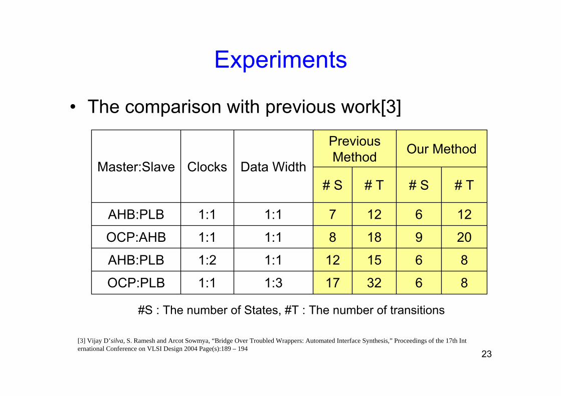
• The comparison with previous work[3]

8632171:31:1OCP:PLB

8615121:11:2AHB:PLB

2091881:11:1OCP:AHB

1261271:11:1AHB:PLB

# T# S# T# S

Our MethodPrevious Method

Data WidthClocksMaster:Slave

#S : The number of States, #T : The number of transitions

[3] Vijay D’silva, S. Ramesh and Arcot Sowmya, “Bridge Over Troubled Wrappers: Automated Interface Synthesis,” Proceedings of the 17th International Conference on VLSI Design 2004 Page(s):189 – 194

24

Conclusion

• Automatic Interface Synthesis based on protocol categorization– Chose an appropriate structure of interface circuits

based on• Interface protocol category• Clock frequency• Data width• System level requirements (by user constraints)

– Protocol Classification• Our Synthesis algorithm selects an interface circuit structure

depending on the classification of interface protocols

25

Conclusion

• Product FSM-based structure– Less data transmission latency– Somewhat larger area and slower maximum

operating frequency• IPC-based structure

– Less states and transitions than product FSM-based in case that IPs use different frequencies and/or data widths.

• The Performance– Comparable with performance of the manual designs

Thank You!


Recommended