Page 1
UNIVERSITY OF SOUTHERN QUEENSLAND
FACULTY OF ENGINEERING AND SURVEYING
AUTOMATIC SPLINT TO PREVENT
SELF-HARM IN AUTISTIC AND BRAIN
INJURED PEOPLE.
DISSERTATION BY
MARK RICHARDSON
IN FULFILMENT OF THE REQUIREMENTS OF A
BACHELOR OF ENGINEERING
(INSTRUMENTATION AND CONTROLS SYSTEMS)
FINAL REPORT DUE
NOVEMBER 29 2015
Page 2
i
Abstract
This dissertation is aimed at providing a less restrictive alternative to applying
restrictive splints to people who display self-injurious behaviour often seen in
people with severe autism or brain injuries.
An electronic method of controlling an elbow jointed splint is explored, designed,
built and tested. The final product, the Dynamic Splint Device (DSD) is a self-
contained electronic joint that utilises an electromagnetic brake controlled by an
Arduino microcontroller electronics board. Sensors measuring elbow joint
rotational velocity, total fist acceleration and bending moments are used to predict
potential impact forces. The device will reduce injury by applying a braking force
to the joint when the predicted impact is greater than an adjustable set-point.
The electronic ratchet developed as part of the braking system has allowed a sense
of not being restrained, as the arm is not restricted from moving to a more open
position. The ratchet has also increased the battery life of the DSD.
Legally, restraints are required to be the least restrictive available. The DSD has
the potential to revolutionise the care of people displaying Self Injurious
Behaviour (SIB) by reducing the need for full restraint. It allows movement in a
safe manner, restores civil liberties, and allows better therapy when compared to
full restraint devices currently available on the market.
Allowing health professionals and carers to build this device is integral to the
design. Open source coding, 3D printable parts and off the shelf components
allows anyone with a computer and a 3D printer to make the DSD, with the only
limitation being that profit is not made.
Page 3
ii
Limitations of Use
University of Southern Queensland
Faculty of Health, Engineering and Sciences
ENG4111/ENG4112 Research Project
The Council of the University of Southern Queensland, its Faculty of Health,
Engineering & Sciences, and the staff of the University of Southern Queensland,
do not accept any responsibility for the truth, accuracy or completeness of
material contained within or associated with this dissertation.
Persons using all or any part of this material do so at their own risk, and not at the
risk of the Council of the University of Southern Queensland, its Faculty of
Health, Engineering & Sciences or the staff of the University of Southern
Queensland.
This dissertation reports an educational exercise and has no purpose or validity
beyond this exercise. The sole purpose of the course pair entitled “Research
Project” is to contribute to the overall education within the student’s chosen
degree program. This document, the associated hardware, software, drawings, and
other material set out in the associated appendices should not be used for any
other purpose: if they are so used, it is entirely at the risk of the user.
© 2014, Mark Richardson. This work is licensed under the Creative Commons Attribution-
NonCommercial-ShareAlike 4.0 International License. To view a copy of this license, visit
http://creativecommons.org/licenses/by-nc-sa/4.0/ or send a letter to Creative Commons, PO Box
1866, Mountain View, CA 94042, USA.
Page 5
iv
Acknowledgements
I would firstly like to acknowledge Evan Williams for providing me with the
initial idea to develop this device, my wife and children for putting up with me
and supporting me throughout this final dissertation, and also throughout the last
10 years of part time study.
Acknowledgement also goes to my friends and extended family who have
contributed more to this dissertation than they realise. Without support from
family and friends, I would have found it difficult to keep focus like I have.
Friends and family have also been used as an essential sounding board on many
occasions.
I would also like to thank Andrew Maxwell, my dissertation supervisor, for
providing me with the guidance required, and for giving me ideas which led to
better outcomes.
Page 6
v
Table of Contents
Contents Page
Abstract........................................................................................................................................ i
Limitations of Use ...................................................................................................................... ii
Certification of Dissertation ..................................................................................................... iii
Acknowledgements ................................................................................................................... iv
Table of Contents ........................................................................................................................ v
List of Figures ............................................................................................................................ xi
List of Tables ............................................................................................................................. xv
Nomenclature ...........................................................................................................................xvi
Glossary of Terms .................................................................................................................. xvii
Chapter 1. – Introduction ...................................................................................................... 1
1.1 Background ............................................................................................................................. 1
1.2 Motivation .............................................................................................................................. 2
1.3 Aims ....................................................................................................................................... 2
1.4 Objectives ............................................................................................................................... 2
1.5 Summary ................................................................................................................................. 3
Chapter 2. - Literature Review ............................................................................................. 4
2.1 Self-injurious Behaviour (SIB) ............................................................................................... 4
2.2 Existing Standards/Best Practices/Ethical Issues .................................................................... 4
2.3 Existing technologies .............................................................................................................. 6
2.3.1 Self –injurious Behaviour (SIB) treatments ....................................................................... 6
2.3.2 Elbow joint movement technology ..................................................................................... 8
Page 7
vi
2.4 Velocity Sensor ....................................................................................................................... 9
2.4.1 Rotational velocity ............................................................................................................. 9
2.4.2 Total Velocity ................................................................................................................... 11
2.5 Speed Control/Brake ............................................................................................................. 11
2.5.1 Active Drive Elements ..................................................................................................... 11
2.5.2 Resistive Elements ........................................................................................................... 12
2.6 Controller .............................................................................................................................. 14
2.7 Forces Causing Harm ........................................................................................................... 17
2.8 Licensing .............................................................................................................................. 19
2.8.1 Copyright .......................................................................................................................... 19
2.8.2 Creative Commons ........................................................................................................... 19
Chapter 3. – Enabling Technologies and Rapid Prototyping .......................................... 21
3.1 Enabling technologies ........................................................................................................... 21
3.2 Rapid Prototyping ................................................................................................................. 22
3.3 Changing Design – Build cycle ............................................................................................ 22
3.4 Low cost Microprocessor ..................................................................................................... 22
Chapter 4. - Methodology .................................................................................................... 24
4.1 Planned Tasks ....................................................................................................................... 24
4.1.1 Research ........................................................................................................................... 24
4.1.2 Research/Theory ............................................................................................................... 25
4.1.3 Design .............................................................................................................................. 25
4.1.4 Build ................................................................................................................................. 26
4.1.5 Evaluate ............................................................................................................................ 26
4.2 Resource Requirements ........................................................................................................ 27
Page 8
vii
4.3 Timelines .............................................................................................................................. 29
4.4 Consequential effects ............................................................................................................ 36
4.4.1 Safety Issues (analysis) .................................................................................................... 36
4.4.2 Environmental Issues ....................................................................................................... 40
4.4.3 Legal Issues ...................................................................................................................... 40
4.4.4 Ethical issues .................................................................................................................... 40
Chapter 5. – Design .............................................................................................................. 42
5.1 Requirements ........................................................................................................................ 42
5.2 Determination of Maximum Speed ....................................................................................... 43
5.2.1 Kinetic Energy Method .................................................................................................... 44
5.2.2 Impulse Momentum Method ............................................................................................ 44
5.3 Determination of braking power ........................................................................................... 45
5.3.1 Confirmation of braking power ........................................................................................ 47
5.4 Determination of Braking Speed Required ........................................................................... 47
5.4.1 Determination of angular acceleration ............................................................................. 48
5.4.2 Determination of time to reach maximum speed of 3 m/s ................................................ 48
5.4.3 Determination of time to reach the face from an arm open position ................................ 49
5.5 Specifications and Rationale for components ....................................................................... 51
5.5.1 Microprocessor ................................................................................................................. 51
5.5.2 Position and Speed detection ............................................................................................ 52
5.5.3 Measurement of Acceleration ........................................................................................... 53
5.6 Electronic Ratchet ................................................................................................................. 54
5.6.1 Analogue-to-Digital Conversion ...................................................................................... 55
5.6.2 Design of strain gauge circuit: .......................................................................................... 57
Page 9
viii
5.7 Interface ................................................................................................................................ 62
5.7.1 Changing design ............................................................................................................... 65
5.7.2 LCD Design...................................................................................................................... 65
5.7.3 Phone Graphics ................................................................................................................ 66
5.8 Arduino Code Design ........................................................................................................... 69
5.8.1 Initial Setup ...................................................................................................................... 69
5.8.2 Phone requests .................................................................................................................. 70
5.8.3 Sensors ............................................................................................................................. 71
5.8.4 Output data to brake ......................................................................................................... 77
5.8.5 Data transfer to phone ...................................................................................................... 79
5.9 Brake Output ......................................................................................................................... 80
5.9.1 Driver circuit .................................................................................................................... 80
5.9.2 Batteries ............................................................................................................................ 81
5.10 Design of Splint .................................................................................................................... 82
5.10.1 Initial design of Parts ........................................................................................................ 83
Chapter 6. – Build and Testing ........................................................................................... 88
6.1 Electromagnetic Brake Testing ............................................................................................. 88
6.1.1 Brake torque test ............................................................................................................... 88
6.2 Arduino Coding and circuit development ............................................................................. 90
6.2.1 Testing inputs ................................................................................................................... 93
6.3 Driver Circuit ........................................................................................................................ 97
6.4 Phone Coding ..................................................................................................................... 105
6.4.1 Local Variables .............................................................................................................. 107
6.4.2 Initialisation of global variables ..................................................................................... 108
Page 10
ix
6.4.3 Connection to Bluetooth ................................................................................................. 108
6.4.4 Exiting the Application .................................................................................................. 111
6.4.5 Brake On Override ......................................................................................................... 112
6.4.6 Speed Control Mode ....................................................................................................... 114
6.4.7 Manual Control Mode .................................................................................................... 116
6.4.8 Reset Functionality ......................................................................................................... 118
6.4.9 Calibration Functionality ................................................................................................ 120
6.4.10 Updates every second ..................................................................................................... 121
6.5 3D Printing ......................................................................................................................... 122
6.5.1 Position Sensor ............................................................................................................... 122
6.5.2 Accelerometer ................................................................................................................ 124
6.5.3 Strain Gauge fitment to forearm piece ........................................................................... 125
6.5.4 Arm Splints .................................................................................................................... 127
6.5.5 Electronics Box .............................................................................................................. 130
6.6 Combined Component Testing ........................................................................................... 132
6.6.1 Torque Strain Gauge ...................................................................................................... 132
6.6.2 Speed Control Testing .................................................................................................... 135
Chapter 7. – Conclusions ................................................................................................... 137
7.1 Overall Results ................................................................................................................... 137
7.2 Learning Curve ................................................................................................................... 137
7.3 The DSD ............................................................................................................................. 138
7.4 Further Research and Recommendations ............................................................................ 139
7.5 Further Work ...................................................................................................................... 139
7.6 Other Potential Uses ........................................................................................................... 140
Page 11
x
List of References .................................................................................................................... 141
Appendix A – Project Specification ....................................................................................... 151
Appendix B – Design Drawings ............................................................................................. 153
Appendix C – 3D Modelling Code ......................................................................................... 159
C.1: Brake Bearing Source Code ..................................................................................................... 159
C.2: Forearm Piece .......................................................................................................................... 164
C.3: Upper Arm Piece ...................................................................................................................... 166
C.4: Lower Arm Backing Plate ........................................................................................................ 167
C.5: Upper Arm Backing Plate ........................................................................................................ 168
C.6: Lower Arm Brace ..................................................................................................................... 169
C.7: Arduino Box ............................................................................................................................. 169
C.8: Potentiometer Bracket .............................................................................................................. 171
Appendix D - Arduino Code .................................................................................................. 172
Main Code ....................................................................................................................................... 172
LCD Display .................................................................................................................................... 180
Appendix E- Arduino Arm Movement Raw Data ................................................................ 185
Appendix F- Phone Application Variables ........................................................................... 192
Page 12
xi
List of Figures
Number Title Page
Figure 2-1: Prime Elbow Splint by Orthomerica ................................................................... 7
Figure 2-2: Cranial Bones .................................................................................................... 18
Figure 2-3: Creative Commons Licencing ........................................................................... 20
Figure 4-1: Project Cycle ..................................................................................................... 26
Figure 5-1: Braking power achieved with 10 Nm brake ...................................................... 46
Figure 5-2: Front Impact Angle ........................................................................................... 50
Figure 5-3: Side Impact Angle ............................................................................................. 50
Figure 5-4: Android Accelerometer Response to Rapid Movement .................................... 53
Figure 5-5: Punches permitted when locked in this position ............................................... 54
Figure 5-6: Strain Gauge forces ........................................................................................... 55
Figure 5-7: HX711 Circuit Diagram (Source: Hobby Components, 2013) ......................... 57
Figure 5-8: Half Wheatstone Bridge Arrangement .............................................................. 58
Figure 5-9: 3d Printed Forearm Dimension Labels .............................................................. 60
Figure 5-10: LCD Menu Structure ....................................................................................... 66
Figure 5-11: Phone Application Layout ............................................................................... 67
Figure 5-12: Filter response to step input ............................................................................ 73
Figure 5-13: Speed PID Controller ...................................................................................... 77
Figure 5-14: Brake Control Driver Circuit ........................................................................... 81
Figure 5-15: Electromagnetic Brake Pictured Apart ............................................................ 83
Figure 5-16: Electromagnetic Brake Parts Pictured Together .............................................. 84
Figure 5-17: Gear Bearing by Emmett. Source: www.thingiverse.com/thing:53451 .......... 85
Figure 5-18: Bearing modifications ..................................................................................... 85
Page 13
xii
Figure 5-19: 3D Model, Upper Arm .................................................................................... 86
Figure 5-20: 3D Model, Forearm ......................................................................................... 86
Figure 5-21: Exploded View of initial 3D Parts Design ...................................................... 87
Figure 6-1: Testing the Electromagnetic Torque ................................................................. 89
Figure 6-2: Chart of Brake Torque/Voltage ......................................................................... 89
Figure 6-3: Brake Temperature with 24 V Applied ............................................................. 90
Figure 6-4: Arduino Circuit Diagram .................................................................................. 91
Figure 6-5: Electronic Wiring Information .......................................................................... 91
Figure 6-6: Veroboard without external equipment ............................................................. 92
Figure 6-7: Veroboard with Components Connected........................................................... 92
Figure 6-8: Accelerometer Graph ........................................................................................ 95
Figure 6-9: Accelerometer Vs Calculation from Position Sensor ........................................ 96
Figure 6-10: Driver Circuit Board........................................................................................ 97
Figure 6-11: Driver Circuit with Batteries in Box ............................................................... 98
Figure 6-12: PWM trace with faulty diode connection ........................................................ 99
Figure 6-13: 490 Hz 25 % Output Trace ............................................................................ 100
Figure 6-14: PWM 32 kHz ringing .................................................................................... 102
Figure 6-15: Addition of 332 nF Capacitor ........................................................................ 103
Figure 6-16: Addition of 470 Ohm Resistor in Gate circuit ............................................... 104
Figure 6-17: PWM 32 kHz with Filtering .......................................................................... 105
Figure 6-18: App Inventor Designer View ........................................................................ 106
Figure 6-19: App Inventor Blocks View ............................................................................ 106
Figure 6-20: Phone Application User Interface with Variables ......................................... 107
Figure 6-21: Global Variables ............................................................................................ 108
Page 14
xiii
Figure 6-22: Opening Screen and List Picker for Bluetooth .............................................. 109
Figure 6-23: Bluetooth Connection Prior to Picking.......................................................... 110
Figure 6-24: Bluetooth Connection After Picking ............................................................. 110
Figure 6-25: Display once connected ................................................................................. 110
Figure 6-26: Exit Button .................................................................................................... 111
Figure 6-27: Exit Application Pop-up ................................................................................ 112
Figure 6-28: Brake On Button ........................................................................................... 113
Figure 6-29: Brake On Display .......................................................................................... 114
Figure 6-30: Speed Control Blocks .................................................................................... 115
Figure 6-31: Speed Control Display .................................................................................. 116
Figure 6-32: Manual Control Blocks ................................................................................. 117
Figure 6-33: Manual Control Display ................................................................................ 118
Figure 6-34: Reset Button .................................................................................................. 119
Figure 6-35: Reset Button Display ..................................................................................... 119
Figure 6-36: Calibration Button ......................................................................................... 120
Figure 6-37: Calibration Button Display ............................................................................ 121
Figure 6-38: 1 Second Block ............................................................................................. 122
Figure 6-39: Potentiometer ................................................................................................ 123
Figure 6-40: Bearing Potentiometer Insert ......................................................................... 123
Figure 6-41: Potentiometer Bracket ................................................................................... 123
Figure 6-42: Potentiometer Fitted to Bearing Unit ............................................................ 124
Figure 6-43: Accelerometer Fitment in Forearm Piece ...................................................... 124
Figure 6-44: Forearm Piece with items fitted..................................................................... 125
Figure 6-45: Strain Gauge Placement ................................................................................ 126
Page 15
xiv
Figure 6-46: Side view of Strain Gauge ............................................................................. 126
Figure 6-47: Initial PVC Splint .......................................................................................... 127
Figure 6-48: Splint Material before and after Forming ...................................................... 128
Figure 6-49: Formed Splints Mounted on DSD ................................................................. 129
Figure 6-50: DSD with Electronic Box Secured with Velcro ............................................ 130
Figure 6-51: Electronic Box ............................................................................................... 131
Figure 6-52: Final DSD Fitted to Arm ............................................................................... 131
Figure 6-53: HX711 Clock pulse and Data trace ............................................................... 132
Figure 6-54: Thickness (t) from edge to cable hole ........................................................... 134
Figure B-1: Brake Bearing Top View ................................................................................ 153
Figure B-2: Brake Bearing Bottom View .......................................................................... 153
Figure B-3: Forearm Piece Bottom View .......................................................................... 154
Figure B-4: Forearm Piece Top View ................................................................................ 154
Figure B-5: Upper Arm Piece Top View ........................................................................... 155
Figure B-6: Upper Arm Piece Bottom View ...................................................................... 155
Figure B-7: Lower Arm Backing Plate .............................................................................. 156
Figure B-8: Upper Arm Backing Plate............................................................................... 156
Figure B-9: Lower Arm Brace (for box) ............................................................................ 157
Figure B-10: Arduino Box ................................................................................................. 157
Figure B-11: Potentiometer Bracket .................................................................................. 158
Page 16
xv
List of Tables
Number Title ................................................................................................................. Page
Table 2-1: Arduino Vs Raspberry Pi .................................................................................... 16
Table 4-1: Parts Funding ...................................................................................................... 27
Table 4-2: Equipment Required ........................................................................................... 28
Table 4-3: Gantt Chart ......................................................................................................... 30
Table 4-4: Risk Matrix ......................................................................................................... 37
Table 4-5: Hazard Analysis.................................................................................................. 38
Table 5-1: Interface Display Decision Matrix...................................................................... 64
Table 5-2: Arduino Digital Data .......................................................................................... 71
Table 6-1: Confirmation of Speed Readings ........................................................................ 93
Table 6-2: Arduino PWM Pre-scaler Values ..................................................................... 101
Table 6-3: Variable Naming Convention ........................................................................... 108
Table F-1: Phone Application Variables ............................................................................ 192
Page 17
xvi
Nomenclature
α Acceleration
Δ Difference
σ Stress (Force/Area)
ε Strain
Ω Resistance in Ohms
θ Angle in Radians (unless degrees is specified)
τ Torque
ω Angular Velocity in m/s
A Current in Amperes
Ax Acceleration in the x direction (x, y and z directions are used)
E Elastic Modulus (Stress / Strain)
F Force
F Capacitance in Farads
g G-Force. Equivalent to 9.81 m/s2
GF Gauge Factor (Ratio of resistance change / Strain)
Hz Hertz in Cycles per Second
I Moment of Inertia
J Kinetic Energy
kg Kilograms
L Length
m Mass
N Newton Force. Equivalent to 1 kg·m/s2
P Impulse. Units in N·s
rad Radians
s Seconds
t Time
v Velocity
V Voltage
W Watts
Page 18
xvii
Glossary of Terms
bps Bits per second
CAD Computer Aided Design
CC Creative Commons
DC Direct Current
DSD Dynamic Splint Device (This project)
ERF Electrorheological Fluid
ET Essential Tremor
IDE Integrated Development Environment
IMU Inertial Measurement Unit
JHA Job Hazard Analysis
MOSFET Metal Oxide Semiconductor Field Effect
MRF Magnetorheological Fluid
MSDS Material Safety Data Sheet
PID Proportional, Integral and Derivative Control Algorithm
PLA Polylactic Acid. This is the 3D printable polymer used.
PWM Pulse Width Modulation
SIB Self-Injurious Behaviour
SMA Shape Memory Alloys
SSI Synchronous Serial Interface
TSD Therapeutic Shock Device
USB Universal Serial Bus
WHS act Work Health and Safety Act
Page 19
1
Chapter 1. – Introduction
Self-injurious behaviour (SIB) is a devastating condition that typically affects
people with severe autism and brain injury. SIB involves multiple self-harm
behaviours, including sufferers inflicting head injuries, which can lead to broken
cranial bones and even acquired brain injuries in severe cases. Many forms of
treatment are available for this condition, however in extreme cases where other
therapies are not working, it is necessary to apply restraint type splints to prevent
injury.
This project explores the ways in which we currently attempt to reduce injury,
brainstorms ways in which we can do this better and then develops a Dynamic
Splint Device (DSD) which restrains the wearer when impact is being attempted
and allows free movement at all other times. From this point on ‘the device’ will
be referred to as ‘the DSD’.
1.1 Background
Studies show that Self-Injurious Behaviour (SIB) Affects between 4% and 12% of
children with severe intellectual disabilities (Matson, Andrasik & Matson 2010).
Research has also shown that there is currently nothing available to help people
with this condition that does not include tying body parts down as a form of
mechanical restraint, ingesting drugs to change the behaviour, or the use of
aversive behaviour therapies including electrical shock.
In Western Australia, the Code of Practice for the Elimination of Restrictive
Practices (Commission, Disability Services 2014) states that restraints should be a
last resort and it must be proven that all less restrictive practices have been
evaluated and cannot be applied.
There are limited choices for a using a least restrictive option when a restrictive
device is required, therefore this project addresses the gap and aims to develop a
restrictive splint that is only restrictive when required and will therefore become
the least restrictive option available.
Page 20
2
1.2 Motivation
The motivation for this project comes from the dilemma faced with carers on how
to prevent people with self-injurious behaviour harming themselves or others.
When a patient exhibits challenging behaviours, as a last resort the people are put
in restraint, however if complete immobilisation is used, once in restraint the arms
cannot be moved at all, which limits development, limits the progression of
behaviour therapies and removes the dignity and freedom during this period.
Another motivation has been that restraint devices available range from complete
immobilisation using beds or chairs, to slightly restrictive cuffs that can reduce
the SIB under control without restricting movement (Federal Drug Administration
Board (FDA) 2014). The problem that carers face is that each of these devices are
only effective for certain conditions and if conditions change, then either the
device is ineffective, or the device is too restrictive, neither of which are in the
best interests of the client (Williams 2015).
1.3 Aims
The aims of this project are to;
Research available devices and technologies to find what is used currently
to prevent harm in people with challenging behaviours such as SIB and
also research technologies that may be utilised to help prevent harm.
Design, build and test a splint device that can electronically controls a
device to minimise harm by detecting when harm is about to occur or has
occurred and only restrict movement during these times.
1.4 Objectives
1. Complete research on self-harm to gain insight to help develop the DSD.
2. Determine the amount of force/velocity required to cause harm, versus the speed
required to use an arm normally for every-day tasks.
3. Research methods to detect acceleration and methods to slow down the
acceleration to determine the most practical methods to detect and control the
elbow joint speed.
Page 21
3
4. Model the forces involved in the elbow joint of the arm and develop a model to
control the forces via a braking mechanism.
5. Develop electronics to amplify the velocity sensor so that the sensor can be used
by a microprocessor circuit.
6. Either program a microprocessor system, or electronically create a control
scheme to control the braking of the arm proportionally dependent upon speed
via an adjustable setting, with the input being the velocity sensor and the output
being a braking mechanism.
7. Create a mechanical system to house the elbow joint and electronics.
8. Test and evaluate the DSD.
9. Submit an academic dissertation on the development of the DSD.
1.5 Summary
This dissertation aims to develop a device which can be used instead of a fixed
mechanical restraint for people with SIB. The device will only restrain someone
when it detects that they are trying to harm themselves and is free to move
otherwise.
The research and development of a device is expected to change the way that
restraint is used to treat people with SIB and a great outcome would ensure that
dynamic devices be the first choice for people needing to be put in restraints.
The outcomes of this project will be used to further develop effective devices
along the same principles which can be made accessible to anyone who requires
it.
Page 22
4
Chapter 2. - Literature Review
The following literature review covers the topics that affect the development of
the DSD. Firstly existing technologies are explored to determine what else is
being designed to address the issue, followed by a review of component
technologies that are required in the device.
2.1 Self-injurious Behaviour (SIB)
Self-injurious behaviour describes non-accidental behaviour which inflicts
damage or destruction of body tissue, which is carried out without suicidal
intentions. Between 4 % and 12 % of children with severe intellectual disabilities
(Matson, Andrasik & Matson 2010) exhibit self-injurious behaviour which may
present as face slapping, head punching, head banging, or other behaviours which
cause harm. In most cases behavioural therapies or treatment of underlying
physical illness stops the self-injurious behaviour.
As explained by Matson (2010), the treatment of SIB behaviour is complex and
should be individual for each patient. There is no single solution which cures the
behaviour and the use of drugs or mechanical restraints is not a solution to the SIB
behaviour, but when other treatment fails to stop the SIB behaviour, restraint may
be used to protect the person. It is important that patient protection is the aim and
not as a solution to stop the behaviour.
This highlights the fact that using restraint is not a treatment for SIB, but a
protective device when all other treatment has proven to not stop the behaviour.
Therefore the DSD should only be used in conjunction with health professionals
as part of a holistic treatment plan.
2.2 Existing Standards/Best Practices/Ethical Issues
A key principle of medical ethics is that a patient’s autonomy should be respected,
therefore there are ethical issues surrounding the use of restrictive splints for
restraint purposes, as it often takes away a person’s autonomy.
In Australia the use of restraints is legislated. In Western Australia, the following
are some of the acts and standards that apply;
Page 23
5
Mental Health Act 2014,
National Standards for Disability Services 2013
Charter of Human Rights and Responsibilities Act 2006
Disability Discrimination Act 1992
National Framework for Reducing and Eliminating the use of Restrictive
Practices in the Disability Services Sector 2014
Disabilities services Act 1993
Children and Community Services Act 2004
Equal Opportunity Act 1984 (WA)
These acts, charters and standards should all be consulted in the use of restraint.
The Western Australian Government’s Office of the Public Advocate has put out
a position statement with regards to protecting the human rights of adults with
decision-making disabilities (Office of the Public Advocate, Governemnet of
Western Australia, Department of the Attorney General 2013). This position
statement explains that because the use of restraint is a major infringement on a
person’s civil liberty, it should only be used as a last resort and all alternative
methods should have been either explored and failed, or inappropriate. Also,
restraint can only be used as part of a holistic intervention plan developed and
approved by a treating team in consultation with the family with the consent of a
guardian. The position statement also states that restraints can only be used if less
restrictive alternatives have been tried and the proposed restraint is the least
restrictive form available.
Legislation also exists in Western Australia in the Health Act 2014 (Government
2014), which states under clause 228, that the degree of force must be the
minimum that is required and the person must be treated with dignity and respect.
The act also states in clause 229 that bodily restraint must only be used in
accordance with an oral authorisation, or a bodily restraint order, with a current
penalty of $6000. Oral authorisation may only be given by a medical practitioner,
mental health practitioner or the person in charge of a ward at an authorised
hospital and is only an emergency measure prior to obtaining a bodily restraint
order (a bodily restraint order must be obtained within 30 minutes of an oral
authorisation, otherwise restraints must be removed). This legislation does not
cover the ongoing use of restraints, which seems to be managed by Disabilities
Services in Western Australia by a code of practice.
Page 24
6
The Code of Practice for the Elimination of Restrictive Practices (Commission,
Disability Services 2014), is part of a Positive Behaviour Framework set out by
the disabilities commission and provides a basis to develop operational policy and
guidelines to eliminate the use of restrictive practices for people with SIB. This
code aligns with the new Standards for Disability Services which has been
adopted by all states. The purpose of this code is to raise the awareness of the
human rights of people with a disability and the eventual elimination of restrictive
practices for people with challenging behaviours. It also provides a framework for
ensuring that restraints are used as a last resort and only if approved by the service
providers Positive Behaviour Support Panel. This panel must be convinced that all
less restrictive practices have been evaluated, cannot be applied and that the
restrictive practice is considered in the context of a positive behaviour support
plan and a person-centred plan.
The development and usage of an electronically controlled device will ensure that
in the instances where there is a requirement for a restrictive device, that the
freedom of movement is maximised. Therefore the ESD will be the least
restrictive device available that adapts to the behaviour of the wearer. If successful
in the treatment of people with challenging behaviours, then the use of this device
will guarantee that restraint is only applied when required and allows complete
freedom of movement otherwise.
2.3 Existing technologies
There are two different areas where existing technologies are relevant. Firstly
technologies that address restricting self-harm and secondly the technologies for
elbow joints to restrict movement.
2.3.1 Self –injurious Behaviour (SIB) treatments
Over the years, SIB has had many treatments. The basis of most treatment is
psychological. Included in the treatments has been the use of adverse stimuli such
as electric shock, water misting, exposure to aromatic ammonia and physical
restraint (Matson, Andrasik & Matson 2009). This adverse stimuli is used as part
of the treatment, however the treatment of SIB is complex and not all treatments
work on all people.
Page 25
7
The only automated device found for the treatment of SIB has been adverse
stimuli devices such as an electric shock device that is applied when impact has
been detected (Salvy et al. 2004). The device applies an ‘adverse stimuli’ and
although controversial, has had some success in reducing SIB frequency.
Many other treatments exist and this review does not attempt to fully explore all
of the treatments available, but attempts to explore the technologies used when
mechanical restraints are required. Nothing could be found that resembled a smart
restraint. There have been many studies completed (Oliver et al. 1998) where an
adjustable style splint has been used which allows varying degrees of freedom.
The Prime(TM)
Elbow splint by Orthomerica has been used to allow the degree of
restraint to be systematically and easily reduced as the SIB behaviour improves.
This splint is designed for limiting postsurgical or post-injury arm motion and
rotation. Movement at the elbow can be increased or decreased in 30 degree
increments allowing for no flexion to full flexion movement. The trials that Oliver
completed showed better results than fixed splints in most cases, even when the
full movement was allowed. Therefore in some cases, a splint with full movement
works, even though it is not restricted in movement. Something else clear in this
study is that not all patients respond the same, so each case must be assessed
individually.
Figure 2-1: Prime Elbow Splint by Orthomerica
After extensive research, as well as conversations with health professionals
working for the Disabilities Services in Western Australia (Williams 2015), it has
proven difficult to find any splint device which is designed to automatically adjust
Page 26
8
to reduce the harm when an impact was imminent and gave free movement
otherwise.
2.3.2 Elbow joint movement technology
Research was completed to find an elbow joint that existed which would brake the
arm and could be easily worn.
The devices found utilised motors, hydraulics or pneumatics for the purpose of
rehabilitation, assisting and human amplification (Gopura, Kazuo & Bandara
2011). These devices are all designed to give more control and strength to the
human body, or are designed to assist in rehabilitation.
At a recent robotics conference, a study was published (Matsumoto et al. 2014) on
a passive exoskeleton device to assist people with essential tremor (ET). The
movement of ET patients could become debilitating while trying to accomplish
basic tasks like eating. The device was designed to reduce compensatory
movement during simple tasks. The device is used to constrain the tremors
passively without the need for motors. This is performed by only allowing a
movement along a certain track, with the forearm rotating when the elbow joint is
bent and is designed to allow the wearer to eat while reducing the effects of the
tremors by restricting all movements other than those required along the path for
eating. This device was one of the few passive devices found, however has a
specific use and therefore found to be not applicable to the DSD.
In a study of resistive torque mechanisms for rehabilitation exoskeletons (Chetran
et al. 2014), rotational Electrorheological Fluid (ERF) and Magnetorheological
Fluid (MRF) brakes were studied with respect to the elbow joint to determine
torques developed and explores the advantages and disadvantages of using rotary
ERF brakes. ERF behaves as a Non-Newtonian fluid when an electric current is
passed through the liquid. Mechanical systems have been developed which
develop torques utilising this technology. These devices can be placed directly on
the elbow joint, however this study concluded that although these ERF devices
have the advantage of developing the torque directly into a resistive joint, they are
not commercially available and must be designed especially for a maximum
required torque. The study also showed that at the moment, the cost is making
Page 27
9
these unaffordable for a viable implementation into the structure of an upper limb
exoskeleton.
The research completed has found no devices that dynamically brake for the
intention of reducing harm from SIB. The research did find resistive torque
mechanisms that could be utilised, however most of these devices are either
expensive, not of the wearable size, or are inappropriate. ERF and MRF fluid
brakes would be ideal to use as the braking mechanism of the DSD due to
lightweight size for the amount of torque, however after extensive research and
many phone calls, only one device suitable was found in the United States which
was a demonstration unit that had not been commercialised. Therefore with the
premise of the DSD being made form off the shelf components, the ERF brake is
not suitable at this time. A request has been made to obtain this demonstration
ERF unit so that it can be evaluated; however it is not clear whether the unit will
be made available at the time this preliminary report was written.
2.4 Velocity Sensor
The measurement to determine impeding impact will be arm velocity. The impact
will be inferred from the rotational velocity of the elbow joint, as the DSD is only
for the elbow joint. It is also understood that impact from a fist is an accumulation
of speed of the elbow joint as well as the shoulder joint. Therefore as well as
velocity measured at the elbow joint, the total linear velocity will also be
measured.
2.4.1 Rotational velocity
In exoskeleton design, encoders are commonly used for rotary speed
measurement; with direction and speed being able to be determined, usually from
a Synchronous Serial Interface (SSI) output for a binary coded absolute precision
data (Avago Technologies 2015). A search was completed at on online store (RS-
ONLINE 2015) for ‘Rotary Encoder’ where 532 rotary encoders were found with
Page 28
10
minimum pulses per revolution of 4001. Low profile encoders all were either
greater than $200, or did not have the required resolution. This renders them
unsuitable for this project and will not be considered further.
Hall Effect sensors, capacitive and inductive sensors can all be used to measure
speed when used with a toothed gear and can determine speed by counting the
number of times a tooth is detected on a toothed wheel. These sensors can be used
if a metal toothed rotating element is utilised such as the devices from Honeywell
(Honeywell 2014) which can come in sizes from surface mount to stainless steel
threaded sensors.
Optical encoders are used throughout the computing industry to read the position
of disk drives, in robotics and elsewhere. The advantage of optical devices is that
there is no requirement for ferrous parts. An encoder disk can be created with
dark/light lines that are picked up by the optical encoder. With this type of
encoder, the distance between the stripes determines the resolution and can be
made to suit the application. Optical encoders do have sensitivity to dirt and dust
so must be kept clean.
Each of the above speed detection devices have either poor resolution, are
expensive, or they are too bulky. Another two options are either using a precision
rotary potentiometer which can be obtained for under $10, or using an electronic
gyrometer. The problem with a gyrometer is that it will measure the total angular
velocity rather than just the angular velocity of the elbow joint and is therefore not
suitable for the elbow joint only. This then leaves the potentiometers which can
give a linear output for position. A precision potentiometer should be used which
has better resolution than a typical wire wound potentiometer.
Therefore for simplicity, a high precision potentiometer will be used and
integrated into the elbow joint.
1 Since we are only measuring around 90 degrees and with a minimum of 1% resolution, we would
need 100 pulses per 90 degrees, which is 400 pulses per revolution.
Page 29
11
2.4.2 Total Velocity
In the last few years, sensing hardware developments have made available
miniaturised inertial and magnetic sensors such as accelerometers and gyroscopes.
These sensors are not only common in robotics and biomechanics, but have also
been used extensively in mobile phones and cameras due to their low cost, small
weight, ease of use and low power consumption. The only downside is that we are
now required to estimate position from acceleration rather than measuring it
directly, however the advantages are that the sensors are no longer required to be
mounted on the pivot point. It can also be difficult to interpret the components due
to gravity compared to the component related to the motion of the object
(Caroselli, Bagala & Capello 2013).
Accelerometers measure the acceleration caused by motion, as well as gravity.
When the sensors are standing still, they measure gravity pulling down on it and
can therefore measure tilt angles by using the 3 degrees of motion in the X, Y and
Z planes.
A gyroscope will allow three-axis angular rate of angular change. An example is
the ST Microelectronics L3G4200D which is a low power (ST Microelectronics
2010) stable device capable of providing a real-time measured angular velocity
through a digital interface (I2C/SPI) capable of measuring rates at a minimum of
+- 250 degrees per second (dps) up to +-2000 dps (user configurable). EBay
currently has these units selling for under $10.
2.5 Speed Control/Brake
Speed control of robotic joints can be achieved either from active drive elements
such as motors, or from resistive elements such as a friction brake. The DSD only
requires the braking force, however both active drive and resistive elements have
been reviewed and they can both provide a braking torque.
2.5.1 Active Drive Elements
Active drive elements include electric motors, pneumatic cylinders, hydraulics
and hybrids of these. One such hybrid found uses pneumatic electric hybrid
actuators with Bowden cables which mimics the way muscles work together to
Page 30
12
rotate an arm (Tomoyuki Noda, Ugurlu & Morimoto 2014). This device has many
elements incorporated to drive the joint. This has been seen as too many moving
parts to be durable in a device which will take some impacts.
Robotics usually favours servo motor drives (Tar, Veres & Cserey 2006) for
robotics due to the ease of controllability and immediate feedback. The servo
motor tries to move to the intended position until it is reached, however there is no
information about the actual position. On the other hand, stepper motors have
constant moment and excellent tuning moment/weight rate. Stepper motors are
used for the low speed high accuracy movements, however are much more
complex to control (Melkote et al. 1999).
Even though the DSD only requires braking torque, the stepper motor was still
considered due to its controllability. One downside to using a stepper motor is that
to have the holding torque to stop or impede a grown person’s strength would
mean that the device could also have the potential to overpower and drive the arm
against someone’s will. This is seen as a safety issue in case of malfunction. It
also required a much larger motor than for one used to simply assist movement.
For instance, an online store (RS-ONLINE 2015) has stepper motors capable of
around 5 N·m which cost between $300 - $400, with a weight starting from
2.8 kg. This is too heavy to be wearable and is also too expensive to incorporate
into the DSD.
2.5.2 Resistive Elements
Conventional Braking system which include drum brakes and disk brakes were
considered, however due to the speed of response, increase in weight and brake
pad wear, these were excluded from the decision.
Eddy current braking is being used within the automotive and locomotive
industries to assist in braking; however they cannot be used alone due to their low
braking torque generation in the low speed region (E Simeu 1996). Studies into
the improvement of low braking torque at low speeds have shown that this can be
improved by the use of different AC waveforms rather than DC (Karako, Afzal. &
Park 2014), however the research is in its infancy and also requires the addittion
of extra electronics to create AC waveforms and so has been disregarded for use
in the DSD.
Page 31
13
A recent review into locking mechanisms for robots published in the IEEE
Robotics & Automation Magazine (Plooij, Mathijssen & Cherelle 2015) compares
the locking devices that have been used in robots. It compares mechanical locking
devices, friction locking devices and singularity locking devices. The review
discusses each device category and uses many categories for comparison. The
comparison highlighted that of the braking devices used to control braking torque,
electromagnetic brakes are one of the better conventional locking devices. This
review also regards piezo actuators as one of the better mechanism if low power
and size is important.
Piezo actuators use the piezo effect of a force creating a voltage, in reverse. A
voltage can create a force in a piezo actuator. These actuators are stacked to drive
a braking mechanism (Plooij, Mathijssen & Cherelle 2015). After trying to find
piezo braking mechanisms in industry, it is clear that these devices are yet to be
commercialised. Piezo actuators could be found (KC Kinetic Ceramics, inc 2015)
(PiezoSystem Jena 2015), however actuators integrated into a brake mechanism
could not be found other than in academic papers (Toyama & Yonetake 2007).
Other searches revealed ultrasonic motors within the hands of robots in low power
situations only (Tang, Sugano & Iwata 2011).
Magnetic Particle brakes were also investigated. These offer good torque control,
simple design and available commercially, however an 8 N·m device weighted
over 3 kg (Sterling Instruments 2015) and a 7 N·m device weighed 3.2 kg (Placid
Industries 2015) which is not a wearable weight.
Shape memory alloys (SMA) such as FlexinolTM
have been used for assisting
muscles (Ammar et al. 2010), in which an alloy is used which experiences change
in shape and hardness when heated, generating a force in the process. These
devices can generate large forces when resistance to its movement is encountered
and can recover large strains. These have been successfully used to mimic muscle
contraction (Ammar et al. 2010), however the articles reviewed have used these
metals to help the contraction rather than impede contraction. Tests on FlexinolTM
(Ali, Wahied & Gihan 2014) show that the alloy has excellent properties for use
in robotics, in that the actuation is silent, no electromagnetic interference, high
power to weight ratio, small physical size and lightweight. The wire temperature
needed to get to around 90 degrees and the phase transformation took
Page 32
14
approximately 0.5 seconds to respond mechanically to the change in temperature.
A paper which discussed the theory, performance curves and design problems of
SMA actuators concluded (Kluszczyn´ski & Kciuk 2013) that SMA actuators
could be used as a special non-standard drive when ultra-light mass and simple
mechanical construction of power feed system is required.
Electro-Magnetic brakes are common in robotics, have good linearity, are simple
devices and are commonly available. Electromagnetic brakes build up a magnetic
field when DC voltage is applied. The field attracts an armature disk to a brake
coil carrier with a friction lining, which creates the braking torque. When the coil
is de-energised, the shaft is free to spin. An internet search on commercial
electromagnetic brakes, found an 8.5 N·m version weighing 0.42 kg (Mayr 2015)
and is typical of the figures found. These electromagnetic breaks are therefore
lighter than all other suitable brakes.
2.6 Controller
Controllers for the DSD were investigated, with the requirement to purchase an
off the shelf controller/processor that is fully customisable with off the shelf
components. The amount off custom electronics is to be kept to a minimum, as the
intent for the project is for it to be easily made by anyone without electronic skills.
The two most popular open source customisable devices found are Raspberry Pi
and Arduino. The Arduino has an 8-bit ATmega series microcontroller with a
clock rate of between 8-16 MHz and 2-8 kB of RAM available. In contrast, the
Raspberry Pi uses a 32 bit ARM processor, with a clock rate up to 1 GHz, with up
to 512 MB of RAM. The main difference between the two being that Raspberry Pi
is a micro-processor which runs LINUX, has a graphics driver, can plug
keyboard, monitor and mouse straight in and therefore resembles a little
computer, while the Arduino is a micro-controller and designed for embedded
applications. The Arduino cannot run an operating system like the Raspberry Pi,
but simply executes code as the firmware interprets it.
The advantages of the Arduino are that it has precise timing unlike the raspberry
Pi, so better for real-time application. It also uses a lot less power (microwatts
compared to watts in standby mode). The Arduino also has many “shields”, which
are plug in devices. There are hundreds of shields available and include motor
Page 33
15
controllers, accelerometers, relay boards, Bluetooth modules, touch screens, as
well as many others. Both of these controllers have a very large community of
users that can be leveraged from and many websites are dedicated to the users of
both of these devices.
A table below compares the main differences between the two. Sources are
element 14 Raspberry Pi datasheet (Element 14 2015) and the Arduino datasheet
(Arduino 2015).
Page 34
16
Table 2-1: Arduino Vs Raspberry Pi
Feature Arduino Uno Raspberry
Pi
Comment
Model R3 Model B
Processor ATMega 328 ARM11
Clock Speed 16 MHz 700 MHz
16 MHz processes 1
scan every 0.625
microseconds. Even if
a command takes 8
clock pulses to
execute, the speeds
are much faster than
the input and output
devices which are
being interfaced with
Flash 32 KB External SD
card
RAM 2 KB
512 MB
(shared with
GPU)
EEPROM 1 KB N/a
Minimum Power 42 mA (0.3W) 700 mA
(3.5 W)
This is a significant
difference for a
battery powered
device.
Input Voltage 7 to 12 volts 5 volts
Analog Input 6 10-bit inputs None
On board analogue
inputs mean Arduino
doesn’t require extra
circuitry for analogue
interfacing
Digital GPIO 14 8
PWM 6 None
This PWM can be
used for the brake
actuation
TWI/I2C 2 1
UART 1 1
SPI 1 1
Dev IDE Arduino Tool
Linux,
Squeak,
IDLE,
Scratch
Ethernet N/a 10/100 Not required
Audio Out N/a HDMI,
analogue
Not required
Video Out N/a HDMI,
composite
Not required
Page 35
17
For the DSD, a full operating system that resides in the Raspberry Pi is not
necessary, as the DSD controller just needs to read inputs and execute outputs,
with addition of an optional Bluetooth interface to communicate to a phone
interface. The low power, on-board input/output, ease of extra input/output
interfacing via shields and application for real time processing along with the ease
of use makes the Arduino the most suitable micro-controller to use.
2.7 Forces Causing Harm
To create a device which limits harm, research was completed in forensic science
and biomechanics to find existing research which indicated the amount of force
which would cause harm.
A study into the mechanics of bruising in living human objects found that they
could determine the mechanical parameters required to cause contusions in a
particular individual by using a striking implement (Geoffrey, Desmoulin &
Anderson 2011). Many studies have been published which involve studies of
contusions post mortem; however few of them study the mechanics of contusions
in the living. This study was on contusions on the lower limbs and concluded that
the Energy absorbed by the limb was a good correlation of whether the victim
bruised or not and energy above 7 Joules caused contusion in most cases.
In another study completed on injury biomechanics (Hayes, Erickson & Power
2007), the impulse-momentum-principle with a factor which accounts for rebound
effects at impact was used. The study shows that using this momentum principle
and using impact duration from other published studies, the impact force can be
calculated. The impulse equation is:
vmtFP ................................................................................................. (2-1)
A study of head injuries caused by blunt force trauma (Sharky et al. 2012) in
which an experimental model was used to assess the force required to cause
damage to the head, revealed that the minimum force for the occurrence of a
laceration was 4 kN.
In another study head impacts from robots were completed on dummies
(Haddadin, Albu-Scha¨ffer & Hirzinger 2008), with forces that would fracture
Page 36
18
bone. The different parts of the head had differing forces to fracture, with the
Maxilla being the least at 0.66 kN The other impact tolerances were Mandible =
1.78 kN, Zygoma 0.89 kN and the cranial bones (Frontal, temporal-parietal and
occipital) at between 3.12 and 6.41 kN. Also, the average contact duration for the
head impact was 0.01 seconds.
Figure 2-2: Cranial Bones
In a study of boxers (Walilko, Viano & Bir 2005), the average punch impact
durations were again measured at 10 ms and with the effective mass of hand at
2.86 kg with a standard deviation of 2.03 kg. The effective mass of the hand was
calculated using the conservation of momentum equation, where mh is the
effective mass of the hand, vp is the hand velocity measured, while vh and m are
the velocity and mass of the test head;
hhph vmmvm ....................................................................................... Equation 2-2
Since this study was investigating the punching force of athletes, with the punch
allowing upper body rotation to increase the punch velocity and hence effective
mass, 2 kg has been chosen as the maximum effective mass that could occur with
self-injurious behaviour and is seen as conservative for the circumstances.
From a study into exoskeletons (Gupta & O'Malley 2008), the maximum elbow
strength was reported as being 72 N·m, however this value was a maximum value
of an athletic adult male. In a study determining the strength of the elbow
(Gallagher et al. 1997), it was shown that the peak torque values for flexion in a
young person was 40 N·m. The mean values for extension were 58.9 N·m in a
young age group (average age 25.6 with a standard deviation of 3.2).
Page 37
19
Therefore to reduce the impact so as not to break a bone, the design will use a fist
mass of 2 kg, an impulse time of impact of 0.01 seconds and will use a figure of
0.66 kN as the force that may break a cranial bone and the energy will need to be
reduced to below 7 Joules.
2.8 Licensing
A decision was made to not Patent the DSD so that it could be available to anyone
who could benefit from it. Patenting the DSD would cost tens of thousands of
dollars and since profit will not be sought, patenting would not be beneficial.
Research was completed to determine if protection at a low cost could be sought
to ensure that no-one else could patent the DSD and also to ensure that everyone
could make the DSD for free and distribute as needed, but not be able to make a
profit from doing so.
2.8.1 Copyright
Copyright is automatically applied and protects the source code of a computer
program; however it only protects the code and does not protect the idea within
the program. Therefore if someone develops code that does exactly the same task
with a different way of coding, then that will not be breaking the copyright (IP
Australia 2015). Therefore copyright will automatically apply to the source code
for the DSD and the 3D printed code which are the most important parts of the
device.
2.8.2 Creative Commons
The creative commons license forms part of copyright law and is a way of
formally allowing people to use copyright information with various restrictions.
This is so that the public can have open access to the information and can also
limit the way the information is disseminated. The intent of the DSD is to allow
public access to the DSD, without someone else being able to profit from it.
Having the DSD in the public domain also means that anyone wishing to improve
on the source codes can, as long as they abide by the licence conditions. CC
licencing can form part of licensing the computer code and the 3D modelling
design, as well as this thesis.
Page 38
20
Creative Commons licences are in effect ready-made contracts for the use of
copyright material. There are 6 Creative Commons licences available, all with
different protection. The licences are irrevocable, so the copyright owner cannot
withdraw the license until the copyright expires.
The Attribution-Non Commercial-Share Alike 4.0 international licence (CC-BY-
NC-SA) allows someone to freely copy, or redistribute the copyright material and
they can remix, transform and build upon the material, as long as they give
appropriate credit to the owner, provide a link to the licence and indicate if
changes were made. Also, anyone wanting to remix, or transform the material
must do so under the same licence and no profit can be made from the use, or it
cannot be for commercial purposes (Creative Commons Organisation 2015).
These licences are completely free and all that needs to happen is for the
following information to be displayed with the material.
© 2014, Mark Richardson. This work is licensed under the Creative Commons Attribution-
NonCommercial-ShareAlike 4.0 International License. To view a copy of this license, visit
http://creativecommons.org/licenses/by-nc-sa/4.0/ or send a letter to Creative Commons,
PO Box 1866, Mountain View, CA 94042, USA.
Figure 2-3: Creative Commons Licencing
The above logo and text will be placed on the ‘Limitations of Use’ page at the
front of this dissertation.
Page 39
21
Chapter 3. – Enabling Technologies and
Rapid Prototyping
The advent of new technologies has allowed society, including engineers, to
develop devices like the DSD which have previously been either not technically
achievable, or not viable due to costs. Technologies such as open source
microprocessors, 3d printing technology, cheap sensors such as accelerometers,
and mobile phone technology are all examples that have enabled devices such as
the DSD to become viable by either costing less, or becoming technically
achievable.
Haptic control of robots for under $200 (Ebay 2015), drones with high resolution
cameras available at low cost, and mobile phones with the capabilities to monitor
sleep patterns, GPS track, or control other devices through either wireless or
Bluetooth technology.
These technologies have allowed the DSD to become a viable low cost device
which can be replicated by anyone in the world who has access to a 3d printer, an
Arduino, other basic components and the internet.
3.1 Enabling technologies
The literature review has demonstrated that there are no devices available which
can dynamically control arm movements to ensure that people displaying SIB
behaviour are prevented from harming themselves or others when required, while
allowing freedom of movement at all other times.
Specific technologies that have enabled this project which would have rendered a
low cost device unviable previously are;
Rapid prototyping made available through low cost 3d printing
equipment
Open Source microprocessors such as the Arduino which can be bought
for under $20 with the capability to process analogue, digital and serial
signals at fast processing speeds.
Sensors such as 3 Axis Accelerometers for under $20 which can be
integrated into microprocessors.
Page 40
22
Cheap user interfaces such as LCD displays (under $20) and Mobile
phones which can easily interface with microprocessors via serial
communications.
Online Community of people using open source technologies which have
enabled both accelerated advancement and online help for users who are
helped by other users.
3.2 Rapid Prototyping
Rapid Prototyping includes a range of techniques which have enabled physical
parts to be quickly fabricated using three-dimensional computer aided design data.
Stereo lithography (STL) is a de facto standard for additive manufacturing in
which the three-dimensional print is built up layer by layer. This is commonly
known as 3D printing and has allowed easy and cost effective manufacture of
plastic parts at low cost.
The cost of 3D printing machines has decreased dramatically in the past 5 years
and has now reached the point where a 3d printer can be bought for under $1000
(3D Printer Superstore 2015).
3.3 Changing Design – Build cycle
The onset of available cost effective 3D printers has allowed the design – build –
evaluate cycle to be modified. Traditionally due to the high cost of manufacturing
one off prototypes, the design phase of equipment is important to get right, as
modifying the design can be expensive. With 3D printers, other than purchasing
the printer, there are no setup costs, therefore the cost of changing the design and
printing another part is inexpensive, as once the 3d design can be modified with
the only cost being the cost of material.
3.4 Low cost Microprocessor
Low cost microprocessors such as Arduino’s have allowed the hobbyist to be able
to program a microprocessor which has on-board inputs and outputs on a single
device. The Arduino Nano has 8 analogue inputs/outputs, 12 digital
inputs/outputs, a programmable serial USART, a 20MHz processor and USB
connectivity with on-board bootloader.
Page 41
23
These devices have allowed flexible programming by allowing modifications to
the code easily without the need for extra components. The only components
required are to protect inputs, or if extra power is required for outputs. Once the
inputs and outputs are designed, changes to the code can be made easily as
required.
As with rapid prototyping, this flexibility in programming has allowed the design
of code to be easily changed without modifying electronics. For example, basic
code can be written and then evaluated early to prove theories and ensure that the
initial design is possible. Once this basic design phase has been tested, either
modifications or additions can be made and further testing completed.
Page 42
24
Chapter 4. - Methodology
This chapter explains how the project is intended to be planned, including the
identification off tasks, resources and the development of a timeline through to
project completion.
The consequential effects are also discussed, including safety issues, sustainability
and ethical issues.
Central to this project is the idea that the Dynamic Splint Device (DSD) must be
affordable and available to anyone who would benefit from it.
4.1 Planned Tasks
4.1.1 Research
The research for the project will need to be across many topic areas;
The technical side of the project needs to be researched to ensure that
the wheel is not re-invented. Existing technologies will be required to be
researched to ensure that the project is unique. The technologies used
will also need to be researched, ensuring that the components chosen are
the most suitable for the task.
Information on self-injurious behaviour will be sought to ensure that the
design of the project is as beneficial as it can be and to remove any
assumptions made regarding the condition.
The building of an adjustable splint mechanically is not the focus of this
project, however is key to the success of making it work. Therefore
research will be undertaken to determine the best way to make the
splint.
Laws and ethics are important factors with the design of a device that
has the intention of restraining people. Therefore the laws and ethics of
using a device like this are researched, as well as exploring how this
device could change governmental policy.
Page 43
25
Since the project is to trying to prevent harm, the damage caused by
impact is researched to try and determine the amount of force that
causes harm so that it can be prevented.
4.1.2 Research/Theory
Research of the forces in the elbow will be completed and control theory used to
control these forces via a braking mechanism and theory will be derived to
determine the right components, including to;
Determine braking force required to slow an arm down (to correctly size
the braking mechanism).
Determine the maximum velocity required to be detected (to purchase
accelerometer)
Determine actuation power required (to determine actuation
voltage/current required to be generated and battery requirements)
Apply control theory to control the arm velocity
Determine the torques involved and consider using a strain gauge to
determine the forces involved while the DSD is locked.
4.1.3 Design
A full risk review will be completed as part of the design phase to ensure that all
safety, environmental and sustainability risks are addressed and mitigated where
required.
The design phase will bring together the information from the literature review
and the theory sections to begin deciding on how the DSD will be put together.
Specifically;
Design of mechanical joint utilising a 3d printer, with the 3D software
code being integral to the design.
Design the electronics to drive the braking mechanism.
Design inputs to the electronics to determine arm speeds and forces.
Design the functionality required.
Design the control, using the inputs to control the braking mechanism.
Page 44
26
Design of an interface for a caregiver or health professional to control the
DSD.
4.1.4 Build
The build phase will involve building to the design safely. Both the electronics
and the mechanical device will be built and integrated. The build phase will revert
back to a design phase wherever problems are encountered which needs redesign.
4.1.5 Evaluate
Evaluation will form each part of the build phase and at the completion of the
build. The evaluation phases will be;
Build DSD to test the strength of the brakes and confirm brake torque.
Evaluate the sensors to ensure the readings are as expected.
Evaluate the brake actuation to ensure the correct braking torque is applied
when requested.
Evaluate the control scheme against the design.
Evaluate the comfort and safety of the DSD
Figure 4-1: Project Cycle
Page 45
27
4.2 Resource Requirements
Funds
This is a self-funded project with an extended budget of $5000. Below is a list of
parts required, noting that the 3D printer and software are not solely for this
project.
Table 4-1: Parts Funding
Parts Price
3D printer $1,600.00
Filament $120.00
Electromagnetic Brake $100.00
ERF Brake $100.00
Arduino Uno $30.00
Bluetooth electronics $20.00
Accelerometer $15.00
Miscellaneous parts $100.00
High Density Foam $40.00
Simplify3D Software $150.00
Hardware $50.00
Strain Gauges $50.00
HX711 instrument amplifier $20.00
Consumables $100.00
Total $2,495.00
Page 46
28
Equipment
The equipment required to complete this project has already been purchased and
no extra equipment is expected to be purchased. A list of equipment that will be
utilised follows.
Table 4-2: Equipment Required
Equipment
3D printer
DC Regulated Power Supply
True RMS Multimeter
Temperature controlled Soldering Iron
Laptop Computer
Workshop with tools
Camera
Digital Oscilloscope
Purchasing Lead Times
Purchasing of parts has been identified as a potential issue. I have therefore
identified all parts that are required and there lead times and purchased them
upfront. At the writing of the preliminary report, the long lead time item
equipment has been purchased and arrived. This included the electromagnetic
brake and the 3D printer.
All other equipment purchased either has a short lead time, or can be purchased at
extra cost with next day delivery from a local on line electronics store that has a
large variety in in stock supplies (RS Components).
Facilities
A Private workshop has been utilised for the development of this project, which
includes a full set of workshop tools and equipment. This workshop is accessible
all hours, so will not be a limitation.
Software
The software utilised for this project is either free software, or has already been
purchased and therefore has not time constraints in obtaining the software.
Page 47
29
The biggest resource requirement issue for the software is the time that it takes to
learn new software packages. The software packages used include 3D printing
software, oscilloscope software, Arduino software and Matlab.
4.3 Timelines
A Gantt chart has been developed for this project and can be seen on the
following pages.
Page 48
30
Table 4-3: Gantt Chart
Page 54
36
4.4 Consequential effects
This project has potential consequential effects that have been identified. Issues
involving safety, the environmental and ethics have been addressed.
Safety issues are addressed by the development of a risk matrix which has been
developed from experience within industry and from this risk matrix a Job Hazard
Analysis (JHA) has been developed to determine mitigations for hazardous tasks.
Environmental issues are addressed within the risk assessment.
There are also legal issues relating to the manufacture of this device. Legal issues
surround the safety of the DSD and also the use of the DSD for restraint.
The ethics of placing a device that is designed to restrain someone against their
will is complex. The following sections discuss an overview of the issues, along
with the legalities and best practices within the health care industry.
4.4.1 Safety Issues (analysis)
On the following page a risk matrix has been developed and applied to a hazard
analysis. The risks reviewed are within the fabrication, testing and ongoing use
phases.
The hazard analysis is task based and analyses the task initially with no controls in
place and then mitigation is put in place, then a second risk assessment is
completed with the mitigation in place to ensure that the risk is reduced to an
acceptable level.
There is a risk that the DSD could be used other than intended and cause harm.
This safety risk has been seen as low, since there are no parts that are driven, the
DSD is seen to be no different to any hinged device. The risks associated with the
device being used on people against their will are seen as an ethical issue and has
been addressed in a later section.
Page 55
37
Table 4-4: Risk Matrix
Page 56
38
Table 4-5: Hazard Analysis
Fabrication Hazard Analysis
POSSIBLE HAZARD CATEGORIES: Gravity, Motion, Mechanical, Electrical, Temperature, Chemical, Radiation, Sound, Environmental
Description of Task Hazard Initial
Risk Level Control Measure to make job safer
Residual
Risk Level
Using Epoxy Glue
Chemical: Epoxy glue is a sensitiser and fumes may
cause appropriate discomfort. Moderate
Wear safety glasses with side shields, appropriate
gloves and use in a well ventilated area. Ensure the
MSDS is available and read.
Low
Environment: Toxic to aquatic organisms Moderate Ensure leftover glue is disposed of in a safe way Low
Working with
240VAC equipment
Electrical: 240VAC equipment poses an electrical
risk High
Ensure that 240VAC equipment is inspected by an
electrician prior to use. Ensure that earth leakage
circuit breakers are fitted and tested.
Low
Prolonged sitting at a
computer
Motion: Prolonged sitting if not managed can cause
strains Moderate
Get up once per hour to stretch. Ensure that the
height of the chair, monitor and keyboard are correct. Low
Creating 3D Prints
Temperature: The temperature of the extruders can
reach over 200 degrees and the bed temperature can
be over 100 degrees
Moderate
Either wear high temperature gloves, or keep away
from the hot extruder and bed when the machine is
turned on
Low
Chemical: ABS and PLA fumes may cause
respiratory Irritation Moderate
Use in well ventilated area. Read the MSDS available
and read prior to use. Low
Chemical: Acetone dissolves ABS, so is used for
creating ABS glue and for cleaning Vapours are
highly flammable and can cause drowsiness. Skin
contact may cause irritation and redness
Moderate Use in well ventilated area. Avoid contact with skin.
Read the MSDS available and read prior to use. Low
Environment: ABS and PLA are not toxic to the
environment, however ABS will not degrade, where
PLA is biodegradable.
Low
Ensure waste is kept to a minimum to reduce landfill.
Re-use ABS where possible to create glues ny mixing
with acetone.
Low
Using workshop
tools and equipment
Mechanical: Workshop tools can cause impact
injuries, eye injuries, cuts and abrasions Moderate
Wear safety glasses with side shields, gloves
appropriate to the task Low
Sound: Workshop tools can be noisy and long term
exposure can cause permanent hearing loss High
Ensure ear plugs are worn when completing noisy
tasks Low
Using workshop
rotating equipment
Motion: Rotating equipment can cause swarf to
become airborne, as well as the added risk of
entanglement
High
Ensure safety glasses are worn, however DO NOT
wear gloves when using rotating equipment due to
the risk of getting the gloves caught in the rotating
equipment. Secure all loose clothing, tie up loose hair
and remove jewellery
Low
Page 57
39
Testing Hazard Analysis
POSSIBLE HAZARD CATEGORIES: Gravity, Motion, Mechanical, Electrical, Temperature, Chemical, Radiation, Sound, Environmental
Description of Task Hazard Initial
Risk Level Control Measure to make job safer
Residual
Risk Level
Working with
240VAC equipment
Electrical: 240VAC equipment poses an electrical
risk High
Ensure that 240VAC equipment is inspected by an
electrician prior to use. Ensure that earth leakage
circuit breakers are fitted and tested.
Low
Fit testing splint
device
Motion: Pinch points in the splint Moderate
Ensure that pinch points are designed out of the
splint.
Wear a long sleeved shirt, or place protective
material over the arm prior to fitment
Low
Mechanical: With the forces involved, the DSD can
break and cause injury. Moderate
Wear safety glasses with side shields and gloves.
Inspect splint before and after every use for damage Low
Ongoing Use Hazard Analysis
POSSIBLE HAZARD CATEGORIES: Gravity, Motion, Mechanical, Electrical, Temperature, Chemical, Radiation, Sound, Environmental
Description of Task Hazard Initial
Risk Level Control Measure to make job safer
Residual
Risk Level
Fitting splint device Motion: Pinch points in the splint Moderate
Ensure that pinch points are designed out of the
splint.
Wear a long sleeved shirt, or place protective
material over the arm prior to fitment
Low
Creating 3D Prints
Temperature: The temperature of the extruders can
reach over 200 degrees and the bed temperature can
be over 100 degrees and therefore can cause burns
Moderate
Either wear high temperature gloves, or keep away
from the hot extruder and bed when the machine is
turned on
Low
Chemical: ABS and PLA fumes may cause
respiratory Irritation Moderate
Use in well ventilated area. Read the MSDS available
and read prior to use. Low
Chemical: Acetone dissolves ABS, so is used for
creating ABS glue and for cleaning Vapours are
highly flammable and can cause drowsiness. Skin
contact may cause irritation and redness
Moderate Use in well ventilated area. Avoid contact with skin.
Read the MSDS available and read prior to use. Low
Environment: ABS and PLA are not toxic to the
environment, however ABS will not degrade, where
PLA is biodegradable.
Low
Ensure waste is kept to a minimum to reduce landfill.
Re-use ABS where possible to create glues ny mixing
with acetone.
Low
Page 58
40
4.4.2 Environmental Issues
Environmental issues are addressed in the hazard analysis above. The materials
used are not harmful to the environment; but will contribute to landfill, however
the design will be for the DSD to last and is therefore not a consumable item, so
landfill contribution will be minimal.
The use of rechargeable batteries in the design will reduce the requirement for
new batteries, and nickel metal hydride batteries are also chosen for
environmental reasons (Ying et al. 2006).
4.4.3 Legal Issues
Under section 23 of the Work Health and Safety Act 2010 (Australian
Commonwealth Government 2014), there is a duty of care to ensure that the DSD
is without risks to the health and safety of people. This clause refers to businesses
and is excluded for volunteer work, of which this is intended to be, however there
is an intention to ensure that we abide by the act as best practice and ensure that
the product is safe for use.
In 2014, a national standard for disabilities services was introduced into the
Disability Services Act as the ‘Disability Services Act (National Standards for
Disability Services) Determination 2014’. In schedule 1 of the these national
standards (Australian Government 2014) it states that service strategies must be
based on minimal restrictive options and are contemporary, evidence based,
transparent and capable of review. To help service providers follow the new
standard and national Code of Practice for the Elimination of Restrictive Practices
(Commission, Disability Services 2014) has been developed and therefore should
be used.
4.4.4 Ethical issues
The aim of the DSD is to better the life of people who are currently being treated
with restraint devices to control challenging behaviour. Ethically, the values of
Page 59
41
this aim is sound, however there are still ethical issues surrounding the use of
these devices at all.
Therefore the use of the DSD shall only be used on people, who have given full
consent for the purposes of testing, or used by a health professional on a person as
part of a holistic intervention program and approved by a treating team in
consultation with the consent of a guardian. The health professional must also
abide by the Code of Practice for the Elimination of Restrictive Practices
(Commission, Disability Services 2014) which provides a framework to ensure
that restrictive practices are a last resort. The use of restraint must also be
approved by the service providers Positive Behaviour Support Panel and it must
be proven that less restrictive practices have been evaluated and proven to not be
applicable, or not to have worked.
In Western Australia where trials are likely to occur, permission to use a restraint
device must be obtained through the Disabilities Services of Western Australia,
sighted and records kept ensuring that all relevant laws and standards are
complied with.
Page 60
42
Chapter 5. – Design
This section describes the design process of the DSD. The requirements are first
outlined and then each part of the DSD design is explored. The sections include;
Determination of the maximum speed of the arm to minimise harm
Calculation of braking power for a 10 N·m brake
Calculations of speed to determine time required to activate braking
Rationale for choosing components
Development of the ‘Electronic Ratchet’ concept
Design of the DSD interface
Design of the Code
Design of the output electronics to the electromagnetic brake
Initial design of the 3D printed splint
5.1 Requirements
Safety. As the device is intended to minimise harm, it is essential that the device
does not cause any harm. The device also has to be perceived as safe by the
carer.
Light with low mass/inertia. The mass of the device must be kept to a minimum
so as not to cause fatigue.
Comfort. As the extended use of this device is probable, the device must be
comfortable to wear and not cause fatigue in the wearer.
Ease of fitment. The device must be easy to apply and remove from the carers
perspective, however must be difficult to remove for the wearer.
DSD response speed. The DSD must respond fast enough to impede any
attempted impact.
Accurate speed sensing feedback. The feedback needs to be accurate enough to
ensure that the DSD can respond in time and accurately.
Reliability. To gain user acceptance for this device, the device needs to be
reliable, with minimum requirement for maintenance.
Page 61
43
Simplicity. The requirement of simplicity of this device is driven from reliability,
a reduction in cost and ease of repair. If the device is kept simple then these
other requirements should be easy to comply with.
5.2 Determination of Maximum Speed
This section determines the absolute maximum speed that the elbow joint should
be limited to. This maximum speed will be derived from calculations of the
maximum forces allowable to minimise harm to the wearer. The area of impact,
mass of fist, velocity and acceleration of the punch, the amount the head moves,
amount fist gives and the condition of the person are all factors that affect the
impact energy transferred to the head. Some assumptions are required, as the
mass, force, speed and duration of impact will be different for each individual and
most of these parameters will be different with each impact attempted.
Assumptions made to allow for a conservative starting point for the calculations
are:
Impact time is 10ms. Previous studies have shown this to be the average
contact duration for head impacts (Walilko, Viano & Bir 2005) and (Haddadin,
Albu-Scha¨ffer & Hirzinger 2008)
The mass of the hand is 2kg. The literature review determined that the
effective mass of a boxers hand when punching was an average of 2.86 kg with
a standard deviation of 2.03 kg (Walilko, Viano & Bir 2005). The effective
mass used was2 kg. The decision was based on:
o People with SIB would typically not be trained athletes
o Punching would not use upper body rotation when self-inflicted
o With a standard deviation of 2.03 kg, people with SIB could be expected
to be at the lower end of the distribution.
o Furthermore, the evaluation of effective hand mass will be different with
each person and the accuracy of the calculations for the design of the
DSD is not imperative, as the carers will have access to adjust the speed
set-point to what is most effective.
Reduction of impact energy below 7 J will not cause contusions (Geoffrey,
Desmoulin & Anderson 2011).
Page 62
44
0.66 kN force may break a cranial bone (Haddadin, Albu-Scha¨ffer &
Hirzinger 2008).
Two methods were used to determine the maximum speed to reduce the harm to
below acceptable levels. The first method uses the kinetic energy equation to
reduce the available kinetic energy below 7 J to prevent contusions, while the
second method uses the impulse momentum principle to reduce the force below
0.66 kN to prevent the breaking of any cranial bones.
5.2.1 Kinetic Energy Method
The equation for kinetic energy is;
2
2
1vmJ ............................................................................................................ (5-1)
Re-arranging this equation determine the velocity from a mass and energy limit;
m
Jv
2 ...................................................................................................................... (5-2)
Therefore using the conservation of energy principles, with a mass of 2 kg and a
force of 7 Joules;
smv /646.22
14
Therefore if the velocity is limited to 2.646 m/s, the energy available will be
limited to 7 J.
5.2.2 Impulse Momentum Method
The impulse momentum principle is used, which is derived from the Force
equation;
amF ..................................................................................................................... (5-3)
Page 63
45
And since acceleration is the change in velocity;
t
vmF
................................................................................................................. (5-4)
Therefore re-arranging to form the impulse equation, which is
vmtFP ................................................................................................. (5-5)
Where P is the impulse in (N·s) and the change of momentum is in Kg·m/s.
Since the mass is constant and the change in velocity is from the velocity to zero
velocity, the determination of the force for a given velocity is changed by the
contact duration time. Therefore the velocity required to limit the force to
0.66 kN, with a fist weight of 2 kg and impulse time length of 10 ms is
determined by first re-arranging equation 1-5 to solve for velocity;
vm
tF
................................................................................................................ (5-6)
Therefore;
smkg
skN/3.3
2
01.066.0
Therefore the velocity would need to be reduced to 3.3 m/s to limit the energy to
0.66 kN.
5.3 Determination of braking power
Braking power is required to reduce the force of the arm and therefore reducing
the velocity and subsequent magnitude of impact. Ideally the braking power is to
be greater than what can be produced by the arm. The aim was to find a brake
with greater than 40 N·m force, which is the force that the average 26 year old
young person can develop (Gallagher et al. 1997).
Research has revealed that the lightest brake available commercially is the
electromagnet, or powder brake. Braking torques of around 40 N·m weigh in
Page 64
46
around 2 kg (Steki 2015), which is too heavy for a long term wearable device,
especially when a splint, batteries and electronics are added to this weight.
Since 2 kg has been considered as too heavy to wear, practical consideration of
the forces required was undertaken. A 10 N·m brake is available at a weight of
0.5 kg (Steki 2015). This 10 N·m was then converted to an equivalent weight
being held in the hand and lifted by moving the elbow joint.
Therefore with Torque being equal to the Force multiplied by the distance;
dF ...................................................................................................................... (5-7)
Therefore the Force is determined by;
dF
Since the distance between the fist and elbow is 0.3 m on an average adult, then
the mass required to cause 10 N·m is;
Nm
Nm33.33
3.0
10
Figure 5-1: Braking power achieved with 10 Nm brake
Therefore 33.33 N which is equivalent to 3.4 kg, is the force that can be added
instantaneously to the arm to reduce the speed, reducing the force available to
cause injury.
Page 65
47
5.3.1 Confirmation of braking power
The biomechanics of the arm is complex and not analogous to a simple torque
rotating an arm, as the torque applied to the muscle is varying and often not
sustained, while the opposing elements are also varying including the friction
caused by opposing muscles, tendons, connective tissue and ligaments are also
varying.
Due to the reduced braking torque available within an acceptable weight limit,
further experimentation was completed to determine if the addition of a 10 N·m
force to the elbow joint would reduce the speed. An electromagnetic brake was
purchased which was capable of providing 10 N·m and strapped to the arm. The
brake was then supplied with power (24 Volts DC) while attempting impact to the
chest area.
This experiment showed that the even though 40 N·m can be generated, a 10 N·m
braking force was sufficient to stop the movement. At 10 N·m the brake could be
overcome. However, it was found that the maximum speed achievable was not
enough to cause injury and the energy required to overcome this torque also
fatigued the wearer.
This experiment showed that punching seemed to be a quick sudden release of
energy rather than a sustained energy release and therefore the constant 10 N·m of
energy release by the brake was sufficient to stop the arm.
5.4 Determination of Braking Speed Required
It is necessary to find the speed the arm can accelerate, so that the speed that a
device will need to react to stop the acceleration of the arm can be determined.
This is determined by calculating the moment of inertia to find the acceleration of
the arm with an applied torque. Once the acceleration is known the time in which
a certain velocity can be achieved can be determined.
Page 66
48
5.4.1 Determination of angular acceleration
If the moment of inertia of the arm is simplified to a cylinder with the 2 kg weight
evenly distributed along the arm, then the moment of inertia (I) equation is:
2
3
1rmI ................................................................................................................... (5-8)
Therefore; 2
2
.06.0
3.023
1
mkgI
I
To determine the angular acceleration from torque and moment of inertia,
Newton’s second law for rotation is used:
I ........................................................................................................................ (5-9)
Therefore; I
So a torque of 40 N·m applied to the elbow joint would accelerate the arm at;
2
2
22
2
/.667
.06.0
.40
.06.0
.40
sradians
mkg
smkg
mkg
mN
5.4.2 Determination of time to reach maximum speed of 3 m/s
The time to reach 3 m/s is then calculated by first converting 3 m/s to radians per
second where;
r
v
.......................................................................................................................... (5-10)
sradm
sm/.10
3.0
3
Page 67
49
Next to determine the time taken to reach the angular velocity of 10 rad/s. The
equation for angular acceleration ( ) is the change in angular velocity ( ) over
the change in time ( t );
t
...................................................................................................................... (5-11)
Rearranging to determine the time taken to reach a given velocity;
t
Assuming that the arm is at rest before the movement, then the time to accelerate
to 10 rad/s is;
ssrad
sradt 015.0
/667
/102
Therefore the time to reach 10 rad/s is 15 ms.
A final check is completed on the distance travelled while accelerating to this
speed, which is calculated by the equation;
2
2
1t ................................................................................................................ (5-12)
Therefore, the angular rotation achieved in 0.015 s under constant acceleration of
667 rad/s2 using equation (5-12) is;
3.4
.075.0
015.0/6672
1 22
radians
ssrad
5.4.3 Determination of time to reach the face from an arm open position
The time taken for the acceleration to reach the face is now determined. These
calculations take into account the time from open to impact. The arm will not
always be in the fully open position, however this is the worst case, as higher
speeds are achievable from a further distance away.
Page 68
50
The below figure shows the likely movement from extended to facial impact and
shows that the angle is approximately 90 ⁰ for impact. This was measured from a
front punching position as well as a side punching position, 90 degrees was
measured in each scenario.
Figure 5-2: Front Impact Angle
Figure 5-3: Side Impact Angle
Therefore, to determine the time of impact if the arm was to continue acceleration
until 90 ⁰ was achieved, we use a form of equation 5-12;
st
t
069.0667
2
Therefore impact is achieved after 69 ms.
Page 69
51
5.5 Specifications and Rationale for components
Following, are specifications and decisions made for the components of the DSD.
The DSD is required to measure inputs to determine position and speed and
control that speed via a braking mechanism.
5.5.1 Microprocessor
The microprocessor is required to;
Scan at a speed faster than 0.015 s, in order to be able to apply an output
before the velocity exceeds the maximum value of 3 m/s. NOTE that
0.005 ms is the minimum acceptable value of scan to ensure sufficient
time to brake.
Be able to brake at least 10 N·m, with an analogue style control
Allow easy programming for modifications
Allow serial communications to interface with external components
Open source coding to allow users to modify as required
Allow at least 4 analogue inputs, 1 analogue output and 6 digital
input/outputs. This will allow for speed, position, acceleration and a spare
analogue, as well as an analogue output for brake control and digital inputs
and outputs for buttons and alarms.
The outcome of research completed favoured the Android family of
microprocessors, however it needs to be determined if these processors are
suitable. The Arduino investigated is the Arduino Nano. The Arduino Nano
utilises the ATmega328 processor. This processor runs at 20 MHz, contains an on
board oscillator, has 6 outputs which can be analogue via pulse width modulation
and active power consumption at 0.2 mA (Atmel 2009). The ATmega328 on
board the Arduino Nano has 12 inputs/outputs, 8 analogue inputs, serial
communication and includes a bootloader to enable easy programming via USB.
The Arduino development environment is free and will run on any computer that
supports Java. All that is required to start programming is a computer with a USB
cable. The open source design of the Arduino allows modification, re-use of code
and will allow a community of ‘Makers’ to modify the code to meet their own
Page 70
52
requirements. This will enable anyone to improve the design from anywhere
around the globe, with the intent that the improvements can be incorporated into
the design.
All of the requirements are met except for the processing speed which needs to be
assessed. The ATmega328 has 20 MHz processing however the potential scan
time needs to be determined.
Scan times are dependent upon the total amount of clock cycles and it is difficult
to determine the final scan time. What can be found is the maximum amount of
clock cycles and the average amount of code that would be allowed. Following
are some facts and assumptions to determine of the ATmega328 is sufficient for
the purposes of controlling the DSD;
20 million clock cycles occur every second.
Most Instructions take between 1 and 3 clock cycles to execute, with an
overage of 1.69 clock cycles, which we can round up to 2 clock cycles per
second for this evaluation.
At 2 clock cycles per instruction, 10 million instructions can be executed
every second
To ensure a 5 ms scan rate (200 Hz), 50,000 instructions can be executed
within the code per scan if run at 10 MHz (10 MHz / 200 Hz).
Allowing 200 lines of code, this allows an average of 250 instructions per
line of code. Note that some lines of code will refer to library functions
which add to this value.
These figures seem feasible. During development, the scan rate will need to be
tested to ensure it is within 5 ms scan rate. This means that the device can react
prior to reaching the maximum speed of 3 m/s and is fast enough to help arrest the
arm before impact.
5.5.2 Position and Speed detection
To keep costs low, a potentiometer has been chosen to measure the position of the
elbow joint. This enables both position and speed via calculation of the change of
Page 71
53
speed over time. The potentiometer is required to be mounted in the centre of the
joint due to its rotating nature.
Acceleration can also be detected with the potentiometer by measuring the rate of
change of speed. However, a decision was made to use an accelerometer to detect
acceleration because, if an accelerometer is mounted close to the fist, then it could
measure total acceleration rather than just the elbow acceleration.
5.5.3 Measurement of Acceleration
The requirement of the accelerometer is to measure acceleration in the arm to
detect potential impact, as well as to detect if impact has occurred.
The accelerometer from an Android phone was used to get empirical data of rapid
elbow flexion movements. The data is below;
Figure 5-4: Android Accelerometer Response to Rapid Movement
This data shows that the acceleration of the arm reaches up to 6 g when the phone
is held in the hand. Note that the individual sensors reached a force of around 4 g
while the total acceleration is measured at 6 g. The total magnitude of acceleration
was calculated by the equation;
222
zyxTotal AAAA .............................................................................. (5-13)
-6
-4
-2
0
2
4
6
8
0 5 10 15 20 25 30
Acc
ele
rati
on
(g)
Time (s)
Accelerometer Response to Rapid Movement
x
y
z
gforce
Page 72
54
The total magnitude measured of 6 g is greater than the magnitude required, as the
data was collected with the phone held in the hand. The accelerometer position
will not be mounted in the hand, but closer to the wrist where it will be convenient
to mount. If the position of the accelerometer is 0.2 m from the elbow instead of
0.3 m where the fist is located, then the acceleration will also be reduced by the
same amount. Therefore an accelerometer with a range of 6 g can measure an
equivalent g-force of 9 g referred to the fist.
The accelerometer is to be used for two purposes;
To record the amount of acceleration achieved to display to the carer
To contribute to the speed control algorithm (derivative action)
5.6 Electronic Ratchet
While brainstorming the control of the DSD, a scenario was discovered which
would allow harm to continue. If the arm was locked in a semi closed position,
even though the elbow joint would be locked, the shoulder movement could still
allow impact to take place, as seen in the below photo.
Figure 5-5: Punches permitted when locked in this position
To prevent this from occurring, it was seen as important to allow the arm to open
when in this position, but not close again. Since motors have already been ruled
out of the design due to weight, a method had to be devised which would allow
Page 73
55
this to happen. The solution to this problem is what will be referred to as the
‘Electronic Ratchet’.
The Electronic Ratchet uses strain gauges embodied into the splint of the forearm.
When the brake is applied, it will detect if the arm is trying to open, or close.
Using the combination of the strain gauge and position sensor, the brake can be
released when the arm is trying to open and applied again if the arm is moving
towards the head.
Two strain gauges are to be installed with epoxy adhesive within the forearm
piece, installed in a cantilever arrangement. The top strain gauge has a
compressive strain ( ) while the lower strain gauge has a tensile strain (+ ).
Figure 5-6: Strain Gauge forces
5.6.1 Analogue-to-Digital Conversion
The HX711 is a 24 bit Analogue to Digital (ADC) converter designed to be used
directly with a Wheatstone bridge strain gauge arrangement (Avia Semiconductor
2014) and can be purchased for around $2 (ebay 2015). Reasons why the HX711
is suitable for this application include;
It keep the design for the strain gauge amplification simple, as it is all
contained on the chip
Allows for flexibility in design since the HX711 is programmable
Low cost
Page 74
56
Can be connected directly to an Arduino device without external circuitry.
Readily available
HX711 has a programmable gain, a full-scale differential voltage of ± 20 mV or
± 40 mV depending upon the gain chosen and a digital serial output. An Arduino
library also exists which is sourced from GITHUB (Bodge 2014). GITHUB is an
online version control hub for software developers and also a place where open
source code can be obtained from. This library function allows a calibration factor
to be set, tares the device and controls the data signals to the HX711, which uses a
software style serial communication to create a clock pulse on one digital pin and
receive transmitted data on another digital pin.
The functions form the library to be utilised are;
set_scale(LC_Cal_Factor): This command sets the gain of the scale to the
value within the brackets.
tare(): This command adjusts the offset to set the scale to zero.
get_units(): This command gets the raw data from the HX711, applies the
offset and scale factor by the equation
get_units = (read_average(times) – offset)/scale
The byte gain can be selected to 64, or 128. The gain was set to 128 to ensure that
the module has high sensitivity. The gain can be reduced within the Arduino code
if required.
A serial interface on board the chip provides a 24 bit output in 2’s complement.
Only two data pins are required. One for the clock pulses (PD_SCK) and one for
the serial output (DOUT). These pins are used for input selection, gain and data
retrieval. The DOUT pin goes low when the module is ready for data retrieval.
The gain is set by the number of clock pulses set;
PD_SCK pulses Input
Channel Gain
25 A 128
26 B 32
27 A 64
Page 75
57
On each positive clock pulse, data is shifted out from the DOUT pin, starting with
the most significant bit first until all 24 bits have been shifted out. Following the
24th
bit the, the DOUT pin goes high and the number of following pulses on
PD_SCK signify the gain used. This functionality is taken care of by the HX711
Arduino library function.
The full scale input range as per the HX711 datasheet (Avia Semiconductor 2014)
is:
GAINAVDDV 5.0 ......................................................................................... (5-14)
Figure 5-7: HX711 Circuit Diagram (Source: Hobby Components, 2013)
The above figure (Hobby Components 2013) shows the circuit that is supplied on
the HX711 module.
5.6.2 Design of strain gauge circuit:
The most common strain gauge values commercially available are 120 Ω and
350 Ω. The 120 Ω strain gauge was chosen to complete design calculations with,
because they are readily available and are also a common resistor value which can
be used to balance the bridge.
A 120 Ω strain gauge was found from the RS ONLINE website (RS-Online
2015). The strain gauge has the following specifications;
Gauge Length 5 mm
Gauge Factor 2.1
Gauge Resistance 120 Ω
Length 9.5 mm
Width 3.5 mm
Page 76
58
To measure the strain of the forearm piece as per Figure 5-8, a half Wheatstone
bridge with two active strain gauges on opposite sides of the forearm piece is
used. When one strain gauge is in compression, the other is in tension and visa-
versa. This amplifies the voltage difference, as well as opposing axial forces.
The resisters and strain gauges form two parallel voltage divider circuits as
follows, where;
= Strain. (Change in length divided by the original length)
= Stress (Force divided by Area)
Rg = Strain Gauge Resistance (R3 and R4)
VEX = Excitation Voltage (Measured between E+ and E-)
VCH = Measured Signal Voltage (Between A+ and A-)
E = Stress ( ) divided by the strain ( )
GF = Gauge Factor (Fractional change in resistance, divided by
the strain)
Figure 5-8: Half Wheatstone Bridge Arrangement
The Wheatstone bridge forms two voltage dividers, one with the resisters R1 and
R2 (A+) and one with the two strain gauges R3 and R4 (A-). The equations for A_
and A- are therefore;
21
2
RR
RVA EX
................................................................................................... (5-15)
43
4
RR
RVA EX
................................................................................................... (5-16)
Page 77
59
Since the measured signal voltage is the difference between A= and A-;
AAVCH ....................................................................................................... (5-17)
Due to R1 and R2 being fixed resisters, A+ should always be;
2
1EXVA ............................................................................................................... (5-18)
Also, with the assumption that the tensile and compressive forces are the same
magnitude, then A equation is
0
0
2R
RRVA EX
................................................................................................... (5-19)
Therefore combining equations (5-20) and (5-21), the measured signal voltage
will be;
0
0
22
1
R
RRVV EXCH ..................................................................................... (5-20)
5.6.2.1 Calculation of strain
The magnitude of strain is given by the following equation (Bentley 2005);
FEtw
xl
2
)(6
........................................................................................................ (5-21)
Where tandwl .,, are shown in the diagram below and x is the distance to the
strain gauge from the pivot point;
Page 78
60
Figure 5-9: 3d Printed Forearm Dimension Labels
The Elastic Modulus (E) of PLA plastic printed from a 3d printer is 3368 MPa
(B.M. Tymrak 2014). With a force of 40 N·m (Gupta & O'Malley 2008) being the
maximum force, the following is an estimation of the build size:
l = 200 mm
x = 60 mm
w = 15 mm
t = 35 mm
NmmNMmm
mmMAX 40
3368035.0015.0
)06.02.0(622
610543 MAX
5.6.2.2 Calculating Change in Resistance and Voltage
The expected change in resistance is calculated as follows:
The calculation for strain is:
1.20
R
RGF (National Instruments 2014) ....................................... (5-22)
Re-arranging equation (5-24) gives
Page 79
61
0RGFR ........................................................................................................ (5-23)
Substituting known values gives the result;
136.0R
To calculate the voltage, ΔR is substituted back into equation (1-20);
mVV
V
MAXCH
MAXCH
83.2
240
136.0120
2
15
_
_
To keep within the limits of the HX711, the next calculation determines the
maximum gain to amplify this 2.8 mV to the maximum of the HX711. The
HX711 datasheet (Avia Semiconductor 2014) states the full scale differential
input range as;
GAIN
VAA SUPPLY
MAX 5.0 ............................................................................... (5-24)
Therefore the maximum gain is determined to be
mV
VGAINMAX
83.2
55.0
883MAXGAIN
Therefore, any gain below 883 will not exceed the requirements of the HX711.
Using the same equation (1-26) and re-arranging to determine the mV range from
a gain of 128:
mVV
GAIN
VV
MAX
MAX
53.19
55.0
5.6.2.3 Calculated digital value range from HX711
Since the HX711 outputs a 2’s compliment number, the maximum max of 223
(one bit for the negative) is 8,388,608.
Page 80
62
Since 40 N·m gives a voltage of 2.83 mV, the sensitivity becomes;
mVNmmV
Nm/13.14
83.2
40 ...................................................................................... (5-25)
To equate this to a digital value from the 24 bit HX711;
The data value per mV is;
mVmV
/20970540
223
............................................................................................ (5-26)
Finally, to determine the data value per Nm, equation (5-28) is divided by
equation (5-27)
Nm/1484113.14
209705
This value will be used as the calibration factor in the Arduino. Note that the
value will be determined empirically. The value is not expected to be exact due to
variability in the young’s modulus, differences in the 3D print and differences in
the strain gauge GF.
5.7 Interface
A requirement to interface with the DSD was identified to;
Adjust the speed set-point depending upon situation
Turn the device on/off
Apply the brake manually if required
Calibrate the sensors (tare the strain gauge and calibrate the
accelerometer)
Turn the ratchet mode on or off
Different methods of interfacing considered were
Local potentiometers to adjust settings and switches to adjust modes,
LCD display with local buttons, with a menu style approach for adjusting
settings
Page 81
63
Infrared Remote control
Android application with Bluetooth connectivity
Advantages and disadvantages of each option were considered. The cost, ease of
use, safety and simplicity were all weighted. The best option is the Android
application with Bluetooth connectivity, because the only hardware required is a
Bluetooth module, the phone application is customisable and can be modified
without any additional hardware.
Page 82
64
Table 5-1: Interface Display Decision Matrix
Page 83
65
5.7.1 Changing design
The above matrix table shows the basis for the final decision. The interface went
through a fluid design process in the early stages of development. The interface
was initially the Arduino environment’s built in serial monitor to both read and
write values. This allowed early coding to take place prior to fully developing the
permanent interface.
The next stage was the design of an LCD. The advantages of the LCD include that
interfacing to the DSD can be done without the need to connect to a computer, not
spending project time learning how to create a phone application, and it gives a
simple user interface to complete most tasks. Disadvantages include the
requirement to scroll through menu items to get to the setting required, and the
inflexibility of being limited to 2 lines of display.
The decision to create a phone application was late in development and a difficult
decision. This project attempts to prove the concept that an electronic device can
stop people with SIB harming themselves. The addition of creating a phone
application does not help prove the concept of the hardware, however following
the completion of this dissertation, the DSD is intended to be further refined for
use in society. Therefore, a phone application made the device safer and more user
friendly. The phone application also enables the design to be easily changed, adds
the advantage of modern phone colour touchscreens and also significantly reduces
the cost and size of the electronic component of the DSD.
5.7.2 LCD Design
The LCD was connected to the Arduino and allowed access to menu style options
which the user can change settings with. The display was organised with the
following menu:
Page 84
66
Figure 5-10: LCD Menu Structure
The LCD light off saves power and forms the start of the menu. Once the
button is pressed, the menu went to the upper menu of “DSD on/off?”. From here,
the or buttons will scroll between settings, the ‘Select’ button will enter the
sub-menu for the setting and the button will return to the main menu. If there is
inactivity for longer than 10 seconds, then the light will automatically be turned
off.
The calibration of the accelerometer is completed by pressing the button while
in the upper main menu.
The Arduino code which drives the LCD display can be seen in Appendix D.
5.7.3 Phone Graphics
To develop the graphics, the functions and interfaces required were first listed.
The main requirement is to be able to request the DSD to:
Brake immediately when required
Put into speed control mode and request a set-point from 0 % to 100 %
Put into manual control mode to adjust the brake output from 0 % to
100 %
Turn the ratchet mode on and off
Secondary requirements of the DSD are to
Calibrate the accelerometer
Calibrate the strain gauge
Page 85
67
Display the maximum speed and force
Reset the maximum speed and force
Display the current strain
Display clearly what mode the DSD is in
Graphics were developed to meet these requirements. Buttons which cannot be
pressed in the current mode are either greyed out or not made visible. Below is a
figure of the screen layout, with all buttons showing. Each button has a name
which is shown in brackets (to be used in the coding) and the horizontal lines
indicate horizontal groups of components with the horizontal label indicated to the
right hand side.
Figure 5-11: Phone Application Layout
To ensure that only relevant information is displayed to the user, the following
rules were used for the display of graphics:
Specific Rules
Page 86
68
Until Bluetooth connected:
Only display the ‘Connect to Bluetooth’ and ‘Exit DSD App’ buttons.
Once Bluetooth Connected Screen;
Remove the ‘Connect to Bluetooth’ button
When Speed Control is off
Do not display the Slider or text box input display related to the speed
control
When Manual Control is off
Do not display the slider or text box input display related to the Manual
control
When the Speed Control is on;
Hide the manual control slider and text input controls.
When Manual Control is on;
Hide the Speed Control slider and text input controls.
When the ‘Force Brake On?’ button is pressed;
Hide the manual and speed control input controls
Grey out the manual and speed control on/off buttons
Generic Rules
Rather than display on and off buttons separately, change the text of the
buttons depending upon the state. For example, change an ‘ON’ to an
‘OFF’ when the button has been switched on.
When the ‘FORCE BRAKE ON?’ button has been activated, change the
background to a red and yellow symbol to signify that braking is in place.
Page 87
69
5.8 Arduino Code Design
The Arduino code is where most of the processing takes place. The code is broken
up into sections that complete the following tasks;
Initial setup of variables, communications and sensors
Accept analogue and digital data from the phone’s Bluetooth serial
connection
Send sensor data and status to the phone for display
Allow calibration of sensors
Use accelerometer, strain gauges and position sensor to calculate position,
speed, acceleration
Process sensors data for PID control of the brake
Output an analogue output to the brake unit
See Appendix D for a full listing of the code.
5.8.1 Initial Setup
The initial setup of the Arduino needs to take into consideration the inclusion of
libraries, variable declarations and the ‘setup()’ function which is the first code to
be executed.
There are two libraries used. One for the HX711 strain gauge amplifier (Bodge
2014), and another for the MMA7361 Accelerometer (jeroendoggen 2012). These
libraries allow for standard library functions to be used.
Data types declared include Boolean, Character, integer, Long and Floating. The
full list can be seen in Appendix D.
The setup function must complete the following tasks:
Begin the serial communications
Set up the accelerometer chip (via library commands)
Set the mode of the digital pins
Call the main function
Page 88
70
5.8.2 Phone requests
The Bluetooth adapter used is a HC-06 Bluetooth to UART serial wireless adaptor
which can be obtained for under $10. The BAUD rate is 9600 bps and the HC-06
connects directly to the hardware serial connection on pins 0 (receive) and 1
(transmit). The default is used with 8 data bits, no parity and one stop bit.
The code to setup communications to receive serial data from the Bluetooth
module is:
Serial.begin(9600);
If the serial is available to read, then the characters are stored into the “recd_data”
variable.
5.8.2.1 Analogue Signals from Phone
Two analogue values are sent from the phone to the DSD. Speed set-point and
Manual output set-point. To differentiate between the two, a leading character is
sent prior to the analogue and a trailing ‘/’ is sent to indicate the end of the
analogue value.
The analogue values sent from the phone are characters, conversion from ASCII
to decimal is required. This is achieved by subtracting the character ‘0’ from the
receiving character. For example, the decimal values for ASCII characters 0-9 are
48-57 (www.AsciiTable.com 2010). Therefore the ASCII character ‘8’ has a
decimal value of 56. Subtracting the ASCII ‘0’ (which is 48) leaves the decimal
value 8.
The speed set point has a leading ‘1’ and the manual set point a leading ‘2’.
Characters are sent one at a time so code is required to decipher the characters and
place them into the correct variables.
The code stores all analogue values in a temporary variable called ‘DigitValue’.
In pseudo code:
If there a digit, then
Page 89
71
Multiply last ‘DigitValue’ by 10, then add the new decimal value of the
digit to the new DigitValue.
Keep doing this with each new digit until a ‘/’ is detected.
After the ‘/’ is detected, determine if there is a leading 1 or a leading 2. Extract the
value by removing the leading 1 or 2 and store the value into either the speed set-
point or manual set-point respectively, ensuring that the variable ‘DigitValue’ is
returned to 0 ready for the next analogue value.
5.8.2.2 Digital Signals from Phone
The digital values sent from the phone have been all chosen as alphabet
characters. This decision was made to ensure that digits sent are for analogues and
digital signals are for digitals. An upper case character will make a Boolean
variable ‘true’, while the lower case character will make the same Boolean
variable ‘false’.
Table 5-2: Arduino Digital Data
Type Character Function
Digital values being turned On and Off
B(on)
b(off) Brake
R(on)
r(off) Ratchet Mode
M(on)
m(off) Manual Output
C (on)
c (off) Speed Control Mode
Digital values as a one shot signal
A Calibrate Accelerometer
L Tare Load Strain Gauge
S Reset Max Speed
F Reset Max Force
5.8.3 Sensors
5.8.3.1 Accelerometer
The accelerometer is an MMA7361 accelerometer that is powered by 5 volts and
generates three analogue outputs representing each axis. Two sensitivities can be
selected, 1.5 g and 6 g via software or a selectable switch. This application uses
the 6g sensitivity and therefore has a sensitivity of 206 mV/g +- 15.5 mV
(Freescale Semiconductor 2008).
Page 90
72
The 3.3 V output from the voltage regulator on-board the Arduino supplies the
accelerometer. The analogue reference pin (AREF) is also supplied by the same
3.3 V supply.
An Arduino library was sourced online (jeroendoggen 2012) which allows for
calibration, as well as retrieval of the axis accelerometer readings.
The total acceleration force is determined by the equation:
222
zyxtotal aaaa ........................................................................................ (5-27)
Note that the total acceleration should always be 1 for a non-moving object due
to the acceleration of gravity.
A first order lag digital filter is used to remove any unwanted noise from the
accelerometer. To determine the filter settings, the maximum response time,
sampling period and amount of change required were determined.
The scan rate of the code is determined to be 5 ms on average. Therefore the
sampling period sT is 5 ms. The maximum response time is experimentally
determined to be half of the time it takes for the arm to reach a distance of
200 mm at 3 m/s and is determined to be 66 ms.
mssm
m
Speed
ceDisT 6.66
3
2.0tan200 ................................................................... (5-28)
To allow an adequate response time, the response time was decided to be 1/3 of
the time required and therefore:
msT
Tr 223
200
With a desired final value of 90 % real value within 66 ms, the following formula
was used to determine the filter coefficient k. With Fr = 0.9. The filter factor is
determined by.
With a first order filter, the time to reach 63.2 % 11 e is in the equation:
Page 91
73
sT
e
1 ....................................................................................................................... (5-29)
where sT is the scan period. To allow the equation to account for times other than
the time constant of 63.2 %, the natural logarithm of the final ratio is equated by
the following equation:
Fr1ln ...................................................................................................................... (5-30)
Therefore to equate the filter constant (k) with inputs of the scan period sT , the
response time sT and the % of final value to be reached within the response time
is:
rs TTFrek
1ln1 .................................................................................................. (5-31)
Therefore, the filter coefficient to reach 90 % within 22 ms with a scan time of
5 ms is;
407.01 022.0005.09.01ln ek
To implement, the following code was used (only x axis shown);
Ax = Ax * (1.00 - FilterAcc) + AxRaw * FilterAcc;
Figure 5-12: Filter response to step input
0123456789
10
0 10 20 30 40 50
A
m
p
l
i
t
u
d
e
ms
k=0.407 (90% within 22ms @5ms scan) Step response 0 to 10
Page 92
74
To calculate the overall force from 3 axis, the equation (5-27) was used;
222
zyxtotal aaaa
TotalAccel = sqrt(sq(float(Ax))+ sq(float(Ay))+ sq(float(Az)));
These equations then form the code which is used in two other areas. The
acceleration is used in the PID controller and also used to record the highest
impact recording on the android application.
5.8.3.2 Speed Sensor
The speed sensor is used for the PID control and to display the highest speed
measurement on the android application.
The elbow joint speed sensor used is a potentiometer connected to the centre of
the shaft. The resistance equates to position and the change in resistance
determines the speed. All angles are in degrees.
Angular Position ( ) is proportional to resistance ( ).
Position = (float(Pot) * 360 / 1023) + Pos_Offset;
Angular Velocity ( ) = dt
d ....................................................................................... (5-32)
Fist Velocity = 360
)2( r ........................................................................................ 5-33)
Where r is the radius from the joint to the centre of the fist (default = 300mm or
0.3m).
The resistance of the POT is 10 kΩ, which is converted as an analogue to 0-1023.
To convert the analogue input to degrees, an Arduino mapping function is used.
The offset is determined when the potentiometer is first installed and should not
require calibration. The offset is designed to allow the extended arm to be 0
degrees and measures a positive value when the arm is in flexion.
The below code segment only executes if the time between the last scan and this
scan (dt) is greater than 5 ms. This is to prevent small numbers causing errors in
Page 93
75
the calculation. The change in time and position are both approximated by the
difference between a previous value and the current value.
currentPotMilli = millis();
if (currentPotMilli - previousPotMilli > 5)
Speed = -(((Position - PositionOld) * 2.00 * PI * Radius / 360.00)
/ max(1, (currentPotMilli - previousPotMilli)));
PositionOld = Position;
previousPotMilli = currentPotMilli;
5.8.3.3 Strain Gauge
The strain gauge is setup via library functions. The functions are to set the scale
and tare the sensor to zero. Note that the calibration factor will be determined
during the initial build.
scale.set_scale(LC_Cal_Factor);//Adjust to calibration factor
scale.tare(); // Tare the load cell to zero
Following the initial setup, the strain gauge is to be calibrated by sending an ‘L’
character via serial communication.
else if (recd_dat == 'L') //*****CALIBRATE LOAD CELL
scale.tare();
recd_dat = 0;
The strain gauge value is returned with the calibration factor and offset from the
tare applied with the following line of code.
StrainGauge = scale.get_units();
The strain gauge is used in the ratchet mode of operation, so further code design is
within the ratchet mode section.
Page 94
76
5.8.3.4 Position Sensor
The position sensor is a simple potentiometer. The potentiometer value is 10 kΩ
and is a 1 resolution potentiometer. The 10 kΩ was chosen to ensure that the
current into the Arduino was safe and also limits the power consumption.
I=5/10 kΩ = 0.5 mA
The datasheet application notes for the ATmega328 (Atmel 2009) states in section
23.6.1 that the ADC is optimised for analogue signals with an impedance of 10 k
or less for the sampling time to be negligible. If greater impedances are used,
then the sampling time will depend on how long the source takes to charge a
14 pF capacitor in the ATmega circuit.
The following code maps the 0-1023 Arduino signal (representing 0-5V) and
converts it to degrees by dividing the value by 1023 and multiplying by
360 degrees.
Pot = (analogRead(SpeedSens)); //Input A4 0-1023 = 360 degrees
Position = (float(Pot) * 360 / 1023) + Pos_Offset;
currentPotMilli = millis();
The following code then converts the position into speed by the
taking the derivative of speed;
dt
d ....................................................................................................................... (5-34)
and;
360
2tan 12 r
cedis
.................................................................................... (5-35)
Therefore;
dt
rdSpeed
360
212 ..................................................................................... (5-36)
Page 95
77
if (currentPotMilli - previousPotMilli > 5)
Speed = -( ((Position - PositionOld)/360 * 2.00 * PI * Radius) /
max(1, (currentPotMilli - previousPotMilli))); //mm/ms, or m/s
PositionOld = Position;
previousPotMilli = currentPotMilli;
5.8.4 Output data to brake
5.8.4.1 PID algorithm
The PID algorithm includes a proportional gain, integral action and derivative
action. The control is a modified traditional PID control, in that the derivative
action comes from an accelerometer, which is inherently the derivative of the
speed for speed control.
The error is first calculated between the speed set-point from the Arduino (with a
set-point range of 0-100 %) and the actual speed. The set-point range has been
converted to 3 m/s to ensure that the maximum value of 3.3 m/s as determined in
section 4.2. Therefore the equation is;
SpeedSPSpeedError 3.33 ...................................................................... (5-37)
Figure 5-13: Speed PID Controller
Page 96
78
if(Auto == true)
Error = max(0, (Speed*33.3) - SpeedSP); //50 is the conversion to
100% where 3 m/s = 100%
GainOut = Error*P_Val;
if (Error > 0)
IntegralOut = IntegralOut + Error * I_Val;
elseIntegralOut=0;
DerivativeOut = Error*max(0,(TotalAccel-100))*D_Val;
PIDOut = DerivativeOut+IntegralOut+GainOut;
BrakeCntrl = round(PIDOut*2.55);
analogWrite(BrakePwm, BrakeCntrl); //Writes the analogue to the
output pin (11).
5.8.4.2 Brake on
Analogue brake control is achieved by using the Pulse Width Modulation (PWM)
output functionality of the Arduino. The analogue output ranges from 0 to 255.
The default frequency is 490 Hz, which does not change during analogue output.
What changes is the duty cycle, or the ratio of on and off, with 0 being at a
constant 0 volts, 255 being at a constant 5 volts and 127 being at 5 volts for half
the time and 0 volts for the other half. This output then drives the magnetic brake
driver circuit.
5.8.4.3 Electronic Ratchet Braking
The electronic ratchet design not only allows the DSD to extend the arm into a
straightened position. With the arm extended to the 90 degree mark no damage
can be done to the face (almost fully extended).
In pseudo code, the idea is;
If Ratchet mode is on then:
If the strain gauge is measuring force towards the face or the speed is
moving towards the face and the position is less than 90 degrees then fully
apply the brake.
If the force is away from the face, then release the brake.
If the ratchet mode is not on then just brake!
Page 97
79
void Braking()
if (Ratchet == true) //If the ratchet is on, then allow
only forward movement until 90 degrees is reached (which is seen
as a safe distance)
if ((StrainGauge > 0.15 || Speed > 1) && Position < 90)
//!!!!!!!!!!!!!!determine from demo trials
// Serial.println("RATCHET on");For debugging
analogWrite(BrakePwm, 255);
if (StrainGauge < -0.15)
analogWrite(BrakePwm, 0);
else
analogWrite(BrakePwm, 255);
// Serial.println("No Rat Brake");
//digitalWrite(BrakeCntrl, HIGH);
5.8.5 Data transfer to phone
The phone accepts data ‘printed’ onto the Bluetooth serial signal from the
Arduino. This is used by the ‘Serial.print’ command. Three items are to be
displayed on the phone, being maximum speed, maximum force and the output
from the strain gauge.
To let the phone know that there are 3 analogue values that need to be stored in
different variables, an ‘An,’ is sent as leading characters. The phone then detects
this and separates the analogues by a comma. Therefore the print command is;
Serial.print("An,");Serial.print(MaxSpeed,1);Serial.print(",");
Serial.print(MaxForce,2);Serial.print(",");Serial.println(StrainGa
uge);
Page 98
80
5.9 Brake Output
There are many braking devices available on the market, however with the
research completed, the simple electromagnetic brake was the device which had
the advantage of being an off the shelf device, comparatively light, simple to drive
and easy to integrate into a wearable device.
To drive the electromagnetic brake, a 24 VDC supply is switched via MOSFET
transistor which is driven from the Arduino Pulse Width Modulated output.
A conventional transistor was considered, however low power usage is a
requirement. The MOSFET is either fully off or fully on, so there is very little volt
drop across the MOSFET when conducting and no current when not conducting
and therefore has very little power loss when compared to driving a transistor
under its saturation limit.
5.9.1 Driver circuit
The driver circuit receives a 490 Hz PWM input from the Arduino and outputs a
PWM 24 VDC signal to the brake. The brake is rated at 15 W at 24 V and
therefore will draw a maximum 0.625 A.
The Harris Semiconductor HUF75339P3 N-channel MOSFET (Harris
Semiconductor 2015) has been used. This was chosen due to the 75 A and 55 V
maximum rating. It has a maximum Drain to Gate Voltage (RGS) of ±20 V, with a
maximum power dissipation of 200 W. It also has a rise time of 100 ns and a fall
time of 70 ns. At 490 Hz, these speeds are more than adequate and the faster the
speed, the less power is consumed.
Figure 5-14 shows the electronic brake driver circuit. D1 is used as a freewheeling
diode to supress any voltage spikes that occur when the voltage is removed from
the brakes inductive load. An IN4004 diode has been used with a 1 volt forward
voltage and is rated to peak surge of 30 A at 400 VDC (Diodes Incorporated
2015). As soon as a spike reaches greater than 1 V it will be supressed.
D2 is a 1N4742A Zener diode which has been sized to protect the MOSFET gate
from higher voltages than designed. The maximum rating is ±20 V, with the
expected voltage from the Arduino being 5 V. The Zener will conduct at 9.1 V.
Page 99
81
Figure 5-14: Brake Control Driver Circuit
R1 is designed for two purposes. Firstly to reduce the current that can be sourced
from the Arduino to the maximum allowed by the Arduino of 40 mA (Atmel
2009). This is calculated by:
12540
5min
mA
V
I
VR
Another reason for the resister is to eliminate any ringing in the MOSFET due to
the gate capacitance.
A 150 Ω resister is used which reduces the current that can be sourced by the
Arduino to 33.3 mA.
C1 is there to reduce any ringing that may be induced from the square wave
PWM. This ringing is caused by parasitic inductances and capacitance in the
circuitry. As the parasitic inductances and capacitances are unknown, C1 will be
determined during the testing of the DSD.
5.9.2 Batteries
The batteries for the DSD will be Nickel-Metal Hydride (NiMH). These batteries
were partly chosen to achieve a target 24 VDC, as three ‘9 V’ batteries can be
used in series to give a total of 25.2 V (each battery has a true voltage of 8.4 VDC
(7 cells at 1.2 V per cell)). NiMH have a high energy density compared to Nickel
Cadmium (NiCad) batteries and have no charging problems like Lithium Ion
Page 100
82
batteries. They are also more environmentally friendly than NiCad and lead acid
batteries (Ying et al. 2006).
The 9 V NiMH battery is commonly sold with a capacity of around 200 mA·h
(Ebay.com.au 2015). Since the majority of the load is from the electromagnetic
brake, with the driving circuit being negligible, the battery should last at the full
load current of 0.625 A;
min2.191
min60
625
200
hmA
hmAt
Under full braking, the brake will last 19.2 minutes, however due to the analogue
style control and the electronic ratchet, the brake is expected to last much longer.
The length of time the battery will last will be subject to rigorous testing in the
future.
5.10 Design of Splint
The splint supports will be designed using 3D Solid Computer Aided Design
(CAD) Modeller and subsequently printed with a 3D printer. The decision for
printing the splint with a 3D printer was for a number of reasons;
Integral to the design of the DSD is ease of reproduction by anyone with a
3D printer and access to simple tools. All parts are designed to be either
off the shelf, or 3D printed, which brings the cost down and allows easy
customisation.
3D printing allows rapid prototyping: This has allowed a ‘print and try’
design style to ensure throughout the design phase any issues are solved
early.
Easy reproduction: If a part breaks, or another part is required, then little
time is wasted in reproducing another part.
Customisable: If parts break, or need adjustments for different people, then
the 3D models can be adjusted easily and further parts printed.
Note that for this dissertation, the 3D printed splint is designed to hold the
components together so that testing can be completed and to prove the concept of
Page 101
83
3D printing the parts. Testing has not been completed on the breaking points of
the pieces and further improvement to the ergonomics of the DSD is required.
The CAD modelling program used will be OpenSCAD which is an open source
free program that is written in a script file that renders the 3D model from the
script. The scripting style makes customising objects easy, as shapes can be
programmed as parameters in source code.
The complete set of parts drawings will be displayed in appendix B while the
OpenSCAD source code for each of these parts is shown in Appendix C.
5.10.1 Initial design of Parts
This section describes the design of the first 3D print for the DSD. As discussed in
previous sections, rapid prototyping is an advantage of 3D printers, so this initial
design does not incorporate the intrinsic mounting of instrumentation, as the
function of the main design is to be proven first.
The function of the 3D print is to house the electromagnetic brake, to allow free
movement of the joint when the brake is not powered and allow the DSD to be
strapped to the arm.
Below is picture of the brake. The rotating part is on the left, the fixed part on the
right and the braking faces are shown;
Figure 5-15: Electromagnetic Brake Pictured Apart
Page 102
84
The next photo is the brake together, showing the position that they need to be
held in for the splint;
Figure 5-16: Electromagnetic Brake Parts Pictured Together
There are 3 main parts to the splint design, the bearing, the upper arm piece and
the lower arm piece.
The bearing is based on a planetary gear set. It has herringbone splines on the
gears, which stops the gears falling out and can handle axial loads. The bearing
design was sourced from Thingiverse.com which is a website for the 3D printing
community to share designs. Emmett Lalish is the author of this part and has
given permission for others to modify his designs (Lalish 2013). Below is a
picture of Emmett Lalish’s original design.
Page 103
85
Figure 5-17: Gear Bearing by Emmett. Source: www.thingiverse.com/thing:53451
The bearing was modified to incorporate a base plate which can be bolted onto the
fixed part on the bottom of the brake. The keyed shaft is designed to fit into the
rotating part which connects to the forearm.
Figure 5-18: Bearing modifications
The upper arm piece bolts onto the top of the fixed part of the brake and has some
slots to allow the splint to be secured to the upper arm.
Page 104
86
Figure 5-19: 3D Model, Upper Arm
The forearm piece has been designed to attach to the centre of the rotating part of
the brake via the keyway and shaft. As with the upper-arm piece, slots exist to
allow it to be strapped to the arm.
Figure 5-20: 3D Model, Forearm
The pieces fit together as per the diagram below. The bottom two parts sandwich
the flange of the fixed part of the brake and bolt together, while the top part for
the forearm will be screwed through the centre to hold it together.
Page 105
87
Figure 5-21: Exploded View of initial 3D Parts Design
The design of the 3d printed parts is continued in the build chapter.
Page 106
88
Chapter 6. – Build and Testing
The build of the DSD had six stages, with the design altering slightly along the
way:
1. Testing of the electronic brake to ensure that the brake performed as per
the datasheet
2. Arduino coding
3. Build and testing of the brake driving circuit
4. Development of the Phone application to communicate with the DSD
5. 3D Printing of the splint material and modification to fit all the
components into the DSD
6. Combining each element together to test the unit as a whole
6.1 Electromagnetic Brake Testing
The brake was tested to ensure that the braking torque was as per the datasheet. A
temperature rise test was also completed to ensure that the brake did not get
dangerously hot.
6.1.1 Brake torque test
To be able to test the brake for torque, the 3D modelled design was printed. The
slots in the forearm piece intended for the straps were used to move a known
weight along the length to determine the N·m torque that the brake would hold.
The results were plotted.
Page 107
89
Figure 6-1: Testing the Electromagnetic Torque
The upper arm piece of the brake was held still while the forearm piece was
positioned horizontal to the ground. A known weight was then suspended from
the brake and the weight moved along until the brake started slipping. This was
completed in 30 mA increments of current while recording the voltage and torque
required to move the brake, and the weight and distance that would cause the
brake to slip. The torque in N·m could then be determined and plotted. Below is a
plot of the torque against voltage.
Figure 6-2: Chart of Brake Torque/Voltage
The above chart shows that the brake is fairly linear, however it does not reach the
10 N·m torque specified on the datasheet, however will still be satisfactory for the
DSD.
0
2
4
6
8
0 5 10 15 20 25
T
o
r
q
u
e(
N
m)
Voltage(V)
Torque Vs Voltage Curve
Page 108
90
The temperature of the brake was measured with an infrared temperature sensor.
The temperature was taken every two minutes for 20 minutes, which is when the
batteries will be depleted.
Figure 6-3: Brake Temperature with 24 V Applied
The temperature did rise, however the temperature reached an acceptable
temperature of just over 30 degrees. The 3D printed plastic used is polylactic Acid
(PLA) which has a glass transition temperature of between 60-65 ⁰C (RepRap
2015), so there are no concerns with the temperatures reached by the brake.
6.2 Arduino Coding and circuit development
The code was written and downloaded to the Arduino. Initially the Arduino was
wired up to a bread board to enable initial testing and debugging. Once the
debugging was completed, a veroboard was used, which is an insulated board with
copper strips on the back. The copper strips were cut to enable the below circuit to
be wired:
20
22
24
26
28
30
32
0 5 10 15 20
Tem
pe
ratu
re (
De
gC)
Time (Minutes)
Brake Temperature with 24 VDC Applied
Brake Temp
Page 109
91
Figure 6-4: Arduino Circuit Diagram
Below is a diagram showing how the veroboard was wired. Chip sockets were
used for the Arduino and Hx711 boards to allow removal of chips and
replacement if required. The chip sockets are shown in the below figure with a
bold black border. The other coloured squares in the grid are male connectors,
which allow the external components to be plugged into the board. The colours
indicated below and right of the main grid are wire colours used which are
externally plugged to the board from the inputs and outputs. Internal wiring is
shown as lines.
Figure 6-5: Electronic Wiring Information
Page 110
92
Below is a photo of the board wired up without the chips or plugs inserted,
followed by a photo of the board with all plugs and chips connected.
Figure 6-6: Veroboard without external equipment
Figure 6-7: Veroboard with Components Connected
Once the circuits were connected, a 9 V Battery was used to power the device. Once
powered, testing was completed to ensure that the sensors were connected correctly. A
USB cable was connected to the Arduino to be able to modify the program if required
and to allow the serial connection to display on the IDE’s serial monitor.
The code was downloaded to the Arduino and the IDE serial monitor connected.
Inserted into the code is commented out ‘Serial Print’ commands to print to the serial
monitor screen parts of the code to test.
Page 111
93
6.2.1 Testing inputs
The inputs were tested first. The raw input was printed to the serial monitor along
with the calculated engineering values.
6.2.1.1 Potentiometer
The potentiometer value was tested, confirming that the position is converted to
an accurate angle. This was tested as correct. Note that once placed into the DSD,
the ‘Pos_Offset’ parameter will need to be adjusted to ensure that the open arm
position is set at 0 ⁰.
The speed value was tested to confirm that the speed value represented the change
in position correctly.
The following table shows the calculated position, with a millisecond value and
the speed value calculated. The calculated speed is confirmed to be correct with
an insignificant difference due to the filter used.
Table 6-1: Confirmation of Speed Readings
Arduino Milliseconds
Calculated Δ time (ms)
Arduino Position
(deg)
Calculated Δ Position
(deg)
Arduino Speed (m/s)
Calculated Speed
1664 133.06 0
1818 154 133.42 0.36 -0.01 -0.012
1972 154 133.42 0 0 0.000
2126 154 133.06 -0.36 0.01 0.012
2281 155 127.43 -5.63 0.19 0.190
2434 153 81.69 -45.74 1.55 1.565
2587 153 49.66 -32.03 1.09 1.096
2740 153 48.26 -1.4 0.05 0.048
2893 153 65.85 17.59 -0.6 -0.602
3048 155 84.15 18.3 -0.62 -0.618
3203 155 101.74 17.59 -0.6 -0.594
3357 154 117.58 15.84 -0.53 -0.539
3513 156 124.27 6.69 -0.23 -0.225
3666 153 122.86 -1.41 0.05 0.048
3819 153 81.33 -41.53 1.41 1.421
3972 153 32.77 -48.56 1.67 1.662
4126 154 41.22 8.45 -0.29 -0.287
4280 154 66.55 25.33 -0.87 -0.861
4433 153 92.6 26.05 -0.89 -0.891
4589 156 112.3 19.7 -0.67 -0.661
Page 112
94
6.2.1.2 Accelerometer
The accelerometer was tested, with the x, y and z axis. Once calibrated, the values
of the accelerometer were observed while the z axis was facing upwards. The
reading was 100 on the z axis and around 0 on the x and y axis. The accelerometer
was then moved in each direction (x y and z) and the measurements corresponded
to the direction of movements.
On the following page is a graph showing the position and speed, as well as the
accelerometer readings. Note that the accelerometer reading is 100 for 1 g and the
speed has been multiplied by 100 so that it is represented with the same scale.
Page 113
95
Figure 6-8: Accelerometer Graph
-300
-200
-100
0
100
200
300
400
10
69
16
44
22
17
27
94
33
74
39
52
45
33
51
13
56
85
62
53
68
31
73
99
79
74
85
45
91
15
96
90
10
26
2
10
84
0
11
42
1
11
99
4
12
57
0
13
14
6
13
72
2
14
30
3
14
88
6
15
46
8
16
05
3
16
63
1
17
20
7
17
79
4
18
36
8
18
94
5
19
51
7
20
09
7
20
67
6
21
25
1
21
82
2
22
39
0
22
95
9
23
52
6
24
10
4
24
71
1
g
(10
0 =
1g)
Milliseconds
Accelerometer Readings: 4 slow movements followed by 4 hard impacts
Speed
Position
Ax
Ay
Az
TotalAcc
Page 114
96
The above graph shows that the speed changes show corresponding
accelerometer changes.
To ensure the accelerometer figure is correct, acceleration has been calculated
from the change in speed and compared on the same graph with the
accelerometer. Note that the accelerometer is total acceleration and therefore
will always be positive. The equation for the calculated value is;
8.9
dt
dv
gCALC
Where dt
dv is estimated by new values and previous values of speed and time;
OLDNEW
OLDNEW
TimeTime
vv
dt
dv
The accelerometer detects the acceleration of gravity, so the graph below has
removed 1 g so that the calculated and accelerometer values can be compared.
The raw data can be seen in Appendix E
Figure 6-9: Accelerometer Vs Calculation from Position Sensor
-1
-0.5
0
0.5
1
1.5
2
2.5
3
0 5 10 15 20 25
g
Time (s)
Total Accelerometer vs Calculated from Position Sensor
Total Acc
CalcAcc
Page 115
97
The figure shows that there is a correlation between the two, however they are not
exactly the same which is what was expected. The four slow movements were not
detected as accurately as the calculated value form the position sensor. The
decision was made to use the accelerometer, due to the advantage of measuring
acceleration when the shoulder is being used for movement and also, the
advantage of being able to measure impact more accurately.
6.3 Driver Circuit
Below is a picture of the brake circuit which has been soldered to a veroboard.
Figure 6-10: Driver Circuit Board
Once soldered, the brake unit was connected to the 3 batteries and inserted into a
plastic box which was bought for the braking drive unit.
Page 116
98
Figure 6-11: Driver Circuit with Batteries in Box
The brake drive unit was then connected to the Arduino and the brake. To test the
brake drive circuitry and the manual control of the brake, the Arduino was put
into manual mode via the IDE serial interface and the brake output was put to
25% (output of 64). Below is a figure of the initial scope trace
Page 117
99
Figure 6-12: PWM trace with faulty diode connection
The blue channel A is the PWM output from the Arduino, while the red channel B
is output from the brake controller to the brake. The signal is inverted due to
measurement being taken from the drain of the MOSFET so when the voltage is at
0 V it is conducting.
The red peaks have amplitude of around 67 V, which could not be sourced from
the batteries, so exceeds the 55 V MOSFET rating. This is from back-EMF caused
by the collapsing magnetic field from the brake which is as an inductor. D1 in the
circuit is designed to stop this behaviour. On inspection, the diode was not
connected properly. Once connected properly, the following trace was recorded
on the scope:
Page 118
100
Figure 6-13: 490 Hz 25 % Output Trace
It now displays a nice square-wave, however the brake behaved like a speaker,
amplifying a sound. The default PWM frequency of 490 Hz was used, which is
within the audible range.
Options to solve this issue included using a capacitor on the input to the
MOSFET, however the MOSFET would be controlled in the active linear region
and would waste power. Another option is to avoid the audible range by
increasing the frequency of the brake to something above 20 kHz (Loisiana State
University 2015). This solution was explored.
6.3.1.1 Increasing the Frequency of the Brake Driver
Within the Arduino, the analogue write value is compared against the value of an
8-bit counter. Timer/counter Control Registers (TCCRnA and TCCRnB) are the
main control bits that control the PWM outputs. The clock set bits (CS) of these
control registers determine the pre-scaler which control the frequency of the
PWM.
Page 119
101
The frequency of the PWM is calculated by the clock set bits of this prescaler, of
which the channel used for the brake uses the Control Register TCCR2B and the
CS bits are stored in the three least significant bits of this register. The calculation
for frequency is;
510
.
N
ff clk
PWM
........................................................................................................ (6-1)
N is the pre-scaler factor with the CS bits as shown in the below table
Table 6-2: Arduino PWM Pre-scaler Values
CS Bits N (Pre-scaler) Frequency
001 1 31372.55
010 8 3921.57
011 32 980.39
100 64 490.20
101 128 245.10
110 256 122.55
111 1024 30.64
To achieve 31,372 Hz, the prescaler bits for TCCR2B is changed to 001.
This is achieved by the following code.
TCCR2B = TCCR2B & B11111000 | B00000001
The bitwise and (&) is to ensure that we keep the existing values of the register
for the 5 most significant bits while the bitwise or (|) is used to enter the new CS
bits.
Once this change was completed, the brake was tested again. The audible noise
had completely disappeared, however when the scope was placed on the circuit,
ringing was observed.
Page 120
102
Figure 6-14: PWM 32 kHz ringing
The ringing only occurred during a small period of time (about 2 μs), however the
concern was that the voltage spiked up to over 50 V.
C1 is a placeholder capacitor to reduce any ringing that may be induced from the
square wave PWM. This ringing was caused by parasitic inductances and
capacitance in the circuitry. The addition of a capacitor dampened the response by
becoming an RC snubber.
To reduce the ringing in the circuit at high frequencies, a number of techniques
were used. These included;
A capacitor across the load to smooth the output
Increasing resistor size into the gate to reduce the gate ringing
Shortening of the component leads to reduce circuit capacitance and
inductances
Page 121
103
Note that the output is not affected by the ringing. The objective of reducing the
ringing is to minimise the voltage peaks that the circuitry has to deal with,
ensuring long lasting componentry.
Trial and error was used for C1 and a value of 332 nF reduced the ringing. The
reduction in peak voltage is from 51 V to 37 V, a reduction of 27.45 % and within
allowable limits of the circuit.
Figure 6-15: Addition of 332 nF Capacitor
The resistance on the gate was also increased. With a resistance increased to
470 Ω the MOSFET drive circuit essentially swamped the drive circuit. A further
reduction in ringing was obtained, however the response was slowed.
Page 122
104
. Figure 6-16: Addition of 470 Ohm Resistor in Gate circuit
The compromise from adding circuitry to smooth the ringing, is that a slower rise
time means that the MOSFET will now spend less time in saturation. It will cause
I2·
R losses and produce heat, however the temperature of the MOSFET was
measured and there was no considerable temperature rise.
The PWM in perspective at 27 % duty cycle has the following image on the
scope;
Page 123
105
Figure 6-17: PWM 32 kHz with Filtering
6.4 Phone Coding
The Massachusetts Institute of Technology’s (MIT) App Inventor was utilised to
develop the Android phone application. MIT administer the web based application
originally developed by Google’s Mark Friedman (MIT App Inventor 2015). App
Inventor allows development of Android applications without text based coding.
The coding is a visual based, drag-and-drop method where building blocks are
used to develop the code.
The visual side of the application was developed within the ‘Designer’ tab, while
the code side of the application was developed with the ‘Blocks’ tab.
Page 124
106
Figure 6-18: App Inventor Designer View
The previous figure shows the designer layout, which has been built as per the
design in chapter 5.
Following is an image of the blocks view:
Figure 6-19: App Inventor Blocks View
Page 125
107
In the following sections, the code will be described first, followed by an image of
the relevant code.
6.4.1 Local Variables
All local variables have been declared in the ‘Designer’ view and are shown in
brackets within the below figure.
Figure 6-20: Phone Application User Interface with Variables
Page 126
108
Table 6-3: Variable Naming Convention
Variable Type Description 1 Description 2
Text Comment Text Comment Text Comment
Picker List Picker Dis Display On On/Off
Sl Slider Ratchet Ratchet Sp Setpoint
Bn Button Exit Exit Set Set Value
Tx Text Box Bt BlueTooth Fc Force
TxInput Text Box for User Input Sp Speed Tor Torque
TxDis Text Box for Displaying Input Input Cb Check Box Man Manual Mode
Hz Horizontal Group Max Maximum
Value
Rs Reset
Cal Calibrate
Tor Torque
The variables follow the following naming convention. Note that the middle or
end parts of the tags are not always present. Refer to Appendix F for a complete
local variable listing.
6.4.2 Initialisation of global variables
The three global variables declared in the ‘blocks’ builder is shown below. They
will be explained further in the code explanations.
Figure 6-21: Global Variables
6.4.3 Connection to Bluetooth
The only buttons displayed prior to Bluetooth being connected are ‘Exit DSD app’
and ‘Connect to Bluetooth’:
Page 127
109
Figure 6-22: Opening Screen and List Picker for Bluetooth
A list picker is used to enable a choice of Bluetooth paired devices to be chosen.
The Bluetooth device must have previously been paired for it to appear in the list.
Once the button is pressed, if the Bluetooth on the phone is enabled, then the
phone will display the addresses and names of Bluetooth paired devices. A
notifier is also displayed stating “If Bluetooth NOT seen, Press BACK and pair
with Device First”. This is a reminder that Bluetooth devices need to be paired
prior to connection.
If Bluetooth connection is not available, then an alert states “Bluetooth NOT
available on Phone”.
The final else statement means that the Bluetooth is installed on the phone,
however not enabled, so the alert states “Press BACK Button and Turn ON
Bluetooth”.
Page 128
110
Figure 6-23: Bluetooth Connection Prior to Picking
Once the Bluetooth item is selected, the Bluetooth Client is connected to the DSD
Bluetooth address.
Figure 6-24: Bluetooth Connection After Picking
Figure 6-25: Display once connected
Page 129
111
6.4.4 Exiting the Application
The exit button stops the application. The back button has been disabled because
if pressed it closes the application and disconnects the Bluetooth. The exit button
is the only way to stop the application. Bluetooth is also disconnected on exit and
an option to not exit can also be selected.
The below figure shows the code for when the exit button is clicked, and the
actions taken. The lower code either exits the application and closes the Bluetooth
connection, or does nothing depending upon which button is pressed.
Figure 6-26: Exit Button
The phone application notification is displayed below
Page 130
112
Figure 6-27: Exit Application Pop-up
6.4.5 Brake On Override
Once a connection is made, the brake can be manually overridden any time via the
‘Force Brake On?’ button. Pressing it will play the alert beep, change the
background image to a red and yellow image and vibrate the phone to alert the
user that they have just manually overridden the brake. The text is then changed to
‘Force Brake Off?’ and a ‘B’ is sent via Bluetooth to tell the Arduino to turn the
brake on.
The code then looks at the text to see if the brake is on or off, as the button text is
changed depending upon the state. If the brake is on and the button is pressed,
then a lower case ‘b’ is sent to the phone to tell the Arduino to turn the brake off
(go back to the last state it was in).
When the ‘Force Brake On?’ button is pressed all the other input boxes become
invisible and the Speed and Manual mode selection buttons become light grey.
Page 131
113
Figure 6-28: Brake On Button
Following is the phones display while the brake is pressed
Page 132
114
Figure 6-29: Brake On Display
6.4.6 Speed Control Mode
Speed control mode is the automatic control. In this mode, whenever the speed is
exceeded, the brake will control the braking via PID control to reduce the speed to
below the set-point. The set-point of 0-100 % corresponds to 0-3 m/s.
If the brake is not in override mode, then the speed control can be switched on. If
the manual control is on at the time then it will get turned off.
Once the speed control is switched on, then the speed set-point automatically gets
set to a 50 % default position. This is a safe start position and ensures that braking
does not occur immediately due to a zero speed set-point A ‘C’ is sent to the
Arduino to tell the Arduino that the Speed control is on and the set-point entry
components are made visible. The slider bar allows an easy touch screen
adjustment, while the text entry allows an exact set-point to be entered. Once the
data is entered into the text box, the ‘Set’ button writes the data to the slider
position to ensure that the slider reflects the set-point entered.
Page 133
115
The set-point data is then sent to the Arduino via Bluetooth, the code puts a
leading 1 on the data and also places a ‘/’ at the end of the text string. The ‘1’
signifies to the Arduino that the data is for the Speed Set-point and the ‘/’ signifies
the end of the speed set-point.
Figure 6-30: Speed Control Blocks
Below is the phone application view when the Speed Control is turned on.
Page 134
116
Figure 6-31: Speed Control Display
6.4.7 Manual Control Mode
The Manual control mode has the same interface functionality as the Speed
Control. The difference being that an ‘M’ is sent to the Arduino rather than a ‘C’
to indicate that the manual mode is on. Other differences are that the set-point
default is 0 and the analogue value sent has a leading ‘2’ rather than a ‘1’.
Manual mode is used to send a manual set-point which drives the brake output. 0
is no output and 100 is full output.
Page 135
117
Figure 6-32: Manual Control Blocks
Below is the phone application view when the Manual Control is turned on.
Page 136
118
Figure 6-33: Manual Control Display
6.4.8 Reset Functionality
The reset button allows resetting of the maximum G-Force and maximum speed
recorded. These maximums are recorded by the Arduino and sent to the phone to
allow the carer to observe the maximum figures.
The resets trigger a notification which allows a selection of either ‘Max Speed’,
‘Max Force’ or to ‘Cancel’. Once a selection is made, either a ‘S’ or ‘F’ is sent via
Bluetooth to the Arduino to request a reset of the maximum speed or force
recorded.
Page 137
119
Figure 6-34: Reset Button
The phone display shows the following notification when the button is pressed.
Figure 6-35: Reset Button Display
Page 138
120
6.4.9 Calibration Functionality
Calibration of both the accelerometer and the strain gauge may be necessary. The
calibrate function on both of these sensors is really a zero offset adjustment rather
than a calibration, as no span is adjusted for. This calibration is acceptable,
because they should read either 1.0 g for the accelerometer when still, or 0 N·m
for the strain gauge when under no strain.
Figure 6-36: Calibration Button
The phone display shows the following notification when the button is pressed.
Page 139
121
Figure 6-37: Calibration Button Display
6.4.10 Updates every second
A one second clock triggers the phone to look for data over the Bluetooth link.
The data being received by the phone is a set of analogue values representing the
maximum speed, maximum force and the torque. These values are sent over in a
specific format. The format begins with a ‘An,’ followed by the 3 analogue values
separated by comma’s.
The code looks to see if the Bluetooth connection is on and if so, stores the bytes
from the Bluetooth in the global variable ‘IncomingData’. This incoming data is
stored in separate bytes split by the commas and stored in ‘IncomingDataSplit’
global variable. A check is completed prior to placing the variables in their
respective positions. If the length of the list is 4 and the first item in the list is
‘An’, then the last three items in the list are stored in the appropriate variables.
From the display, a check is made of the Bluetooth connection and if connected,
ensures that all the buttons are displayed except for the Bluetooth connection
button. If the Bluetooth connection is lost, then these buttons are made invisible.
Page 140
122
Figure 6-38: 1 Second Block
6.5 3D Printing
The initial design was printed and the central part of the splint, being the bearing
and rotating system worked well.
The aspects that needed modifying included:
Addition of places to mount the instruments
The splint would slip. Modifications were made to allow bolting
Design a box to mount the controller
Strengthen the forearm piece
6.5.1 Position Sensor
The potentiometer needed to be mounted on the base of the bearing, with the shaft
inside the bearing and the head of the potentiometer kept in a static position. The
centre of the plastic bearing was modified to include a tolerance fit hole for the
shaft and a slot was inserted which accepts a 1 mm strip of metal to ensure the
shaft does not slip.
Page 141
123
Figure 6-39: Potentiometer
Figure 6-40: Bearing Potentiometer Insert
To ensure the head does not move, a brace was made which spans the base of the
brake.
Figure 6-41: Potentiometer Bracket
Page 142
124
Figure 6-42: Potentiometer Fitted to Bearing Unit
6.5.2 Accelerometer
The accelerometer was mounted as far forward within the forearm piece as
possible, within a recessed area. To recess the accelerometer the wires were
soldered directly to the accelerometer rather utilising the plug.
Figure 6-43: Accelerometer Fitment in Forearm Piece
The below figure shows the placement of the accelerometer electronics, the bolt
addition and how the rotating part of the brake is fitted.
Page 143
125
Figure 6-44: Forearm Piece with items fitted
6.5.3 Strain Gauge fitment to forearm piece
The strain gauges need to be bonded to the forearm piece. Epoxy Resin has been
used as the bonding agent. Considerations in the design were to ensure:
There was enough room for the strain gauges and the passive resistors. For
the resistors to allow temperature compensation they need to be mounted
with the strain gauges
Allow wiring of the strain gauges
The figure shown below shows the design and the strain gauges assembled within
the forearm piece
Page 144
126
Figure 6-45: Strain Gauge Placement
The strain gauges along with the resistors and cables were glued into position. The
photo above shows the strain gauges glued, however the resisters were yet to be
glued in place.
The next figure shows the side view of the strain gauge epoxied in place.
Figure 6-46: Side view of Strain Gauge
Page 145
127
6.5.4 Arm Splints
Note that this project is not about the mechanical design but the electronic and
controls of the unit. Therefore the splint component built into the unit is for the
prototype to be tested and will not form part of the final design. Without it, testing
could not be completed.
The images below show the initial attempt at a splint. This used PVC which was
formed to the shape of the arm. This design impeded testing, as the splint slid
down when the arm was attempting impact with the brake locked.
Figure 6-47: Initial PVC Splint
Page 146
128
A better splint was created from a mesh material purchased from a splint making
supplier. The material can be formed into shape after being placed in boiling
water.
Figure 6-48: Splint Material before and after Forming
The formed splints were bolted onto the upper arm and forearm pieces. Extra 3D
printed parts were designed to spread the load of the bolts and to allow a more
comfortable splint.
Page 147
129
Figure 6-49: Formed Splints Mounted on DSD
The electronics were secured with Velcro to the splint, however this did not work
well as the box was not secured well enough and would slip.
Page 148
130
Figure 6-50: DSD with Electronic Box Secured with Velcro
6.5.5 Electronics Box
The electronics box was designed to house the battery and electronics in a
separate section. Designing a box allowed the size to be customised and also
allow for all securing holes to be specific for the application. Other customisations
included:
Bolt holes to line up with the splint bolts
Built up area on lid to allow screwing of the brake drive electronics box to
the lid
Slot wide enough for all wires
Hole for on/off switch on the side
Page 149
131
Figure 6-51: Electronic Box
The below image shows the DSD with the new electronic box fitted to the arm.
Figure 6-52: Final DSD Fitted to Arm
Page 150
132
6.6 Combined Component Testing
Once the 3D components were complete, the device was mounted on the arm and
trialled. This is the first time that the strain gauge Electronic Ratchet and speed
control could be tested.
6.6.1 Torque Strain Gauge
The first test completed on the torque strain gauge was to measure the clock
(PD_CLK) and data (DOUT) pulses from the HX711 strain gauge amplifier board
to confirm the gain of 128 and that it was transmitting data.
Figure 6-53: HX711 Clock pulse and Data trace
The data above was completed using an oscilloscope and shows the PD_SCK
clock cycle in blue (upper trace) and the DOUT data in red (lower trace). This
signal is 2’s compliment with the MSB on the left hand side (Avia Semiconductor
2014).
The 25th
clock cycle confirms that the HX711 gain is set to 128 and the initial data
pin going low signifies to the HX711 that the data is ready to be transmitted. The
24 bit 2’s compliment data has a decimal range of -8388608 to 8388607.
The data in the above figure converts to – 65537, which is equivalent to -0.78 %
in a range of -100 % to 100 %.
Page 151
133
To compare the strain gauge against the designed values, a 1 Kg mass was placed
at a known distance of 150 mm from the strain gauge to give a known torque.
dF ...................................................................................................................... (6-2)
Therefore:
mN
msmkg
47.1
15.0/81.91 2
The calculated calibration factor from the design is 14,841 / N·m. This would
result in a number of:
816,2147.1841,14
A value of 742,050 was received rather than the calculated 21,816. This value was
incorrect by a factor of about 34.
6.6.1.1 Investigating strain Error
Note that the accuracy of the strain gauge is unimportant for the success of the
electronic ratchet, however an investigation took place to understand where the
error may have come from. This investigation found a number of ways in which
an error of such magnitude could have occurred.
The study researched (B.M. Tymrak 2014) which revealed the Elastic
Modulus of 3368 MPa was tested on material printed with a 100 % infill.
The DSD was printed at 15% infill and therefore the value could be much
lower. Two studies subsequently reviewed have measured the Elastic
Modulus as low as 1000 MPa for a 10% infill (Antonio Lanzotti 2015) and
(3D Matter 2015).
The PLA has a clearance through the centre for the sensor cables to go
through and therefore the effective thickness (t) and width will be less than
measured. The measured thickness (t) value to the cable whole is 15 mm
and the width (w) is 10 mm.
Page 152
134
Figure 6-54: Thickness (t) from edge to cable hole
The strain equation can increase by a large amount if the new thickness, width and
elastic modulus figures are used in equation (5-21)
FEtw
xl
2
)(6
Determining the factors that Eandtw ., 2 increase by:
w t E
Original 15 0.035 3368
New 10 0.015 1000
Factor (1/(Original/New)) 1.5 2.33 3.37
Total Factors ( Etw 2 ) 27.51
These calculations have shown that if an error by a factor of 27 is feasible, then
the measured error factor of 34 is also plausible.
6.6.1.2 Adjusting strain gauge calibration factor
To determine the new calibration figure, the old calibration figure is multiplied
50/1.47, which is 34.01.
Page 153
135
646,520.
01.345307.
ValuenCalibratio
ValuenCalibratio
This calibration factor was then used in the Arduino code in the ‘LC_Cal_Factor’
variable.
6.6.1.3 Testing the Electronic Ratchet
The Electronic ratchet control was tested by pressing the ‘Brake On’ button while
the ‘Ratchet Mode’ check box was selected.
The ratchet worked, however a couple of issues were encountered.
The speed threshold which turns the brake on when movement towards the
face is attempted was set at 1 m/s which was too high. This allowed the
arm to easily keep in a closed position rather than forcing the arm straight.
The force required to keep the brake on when moving towards the face
was slightly too high, allowing the brake to be released too early.
The speed threshold and the strain gauge value was reduced from 1 m/s to 0.2 m/s
and from 0.15 N·m to 0.10 N·m respectively. Once completed, another test was
completed.
The ratchet worked better than expected. Any attempt to move the arm towards
the head would secure the brake, while only a slight force trying to open the arm
was required to completely release the brake allowing the arm to freely extend.
The ratchet was tested with multiple attempts open then quickly attempt impact,
as well as slower attempts, however the ratchet would stop the action every time
prior to impact. The ratchet also gave a feeling that the arm was not restrained, as
it could easily be moved in the open direction, and while in a mostly open state
(greater the 90 ⁰ from closed position) the brake was completely free.
6.6.2 Speed Control Testing
The testing of speed control was completed by entering in a set-point and trying to
attempt impact. When the set-point was raised, the speed that could be reached
without braking increased. The output was quite bumpy initially due to an
overactive controller. As soon as the speed set-point was exceeded the brake came
Page 154
136
on hard enough to slow the speed instantly, which allowed the brake to be
released (as the speed was now below set-point).
When impact was attempted, the brake output would increase which reduces the
speed of the elbow joint to below the set-point at times, which would cause the
controller to reduce the output. This reduction in output allowed impact a few
times during testing.
A modification was made to the speed controller, so that if 1 N·m of force was
acting on the strain gauge during speed control braking, then braking would be
increased to 100 % and will not release while the torque is greater than 1 N·m.
// If while breaking the strain gauge measures an increase in
force which may cause impact, then apply brake fully
if (StrainGauge > 1.0)
BrakeCntrl = 255;
This worked very well. Attempted impact while in speed control was impeded.
The following code addition was placed within the PID speed control code and
can be seen in context in appendix D.
Page 155
137
Chapter 7. – Conclusions
7.1 Overall Results
The project aim was to develop a splint device that electronically restricts the
speed of rotation of the elbow joint to minimise harm in people who self-harm.
This has been accomplished, with a device that can be used with people living
with SIB.
The research has shown that there is nothing available to restrict movement and
minimise harm when required, while giving freedom of movement when not
required, for people living with severe autism or brain injuries who display self-
injurious behaviour. The DSD will give an alternative to current methods which
either totally restrain arm movement, involve aversive therapies such as shocking
after impact is detected, or protect the head impact by using boxing head guards
and boxing gloves.
Each of the program items within the original specification has been met, with
many items being exceeded, including:
3D printing the device has allowed rapid prototyping to improve the
design quickly, and will allow subsequent models to be easily reproduced.
3D printing also allows the components to be parameterised allowing
modifications to be made to suit different people
The Electronic Ratchet was not a part of the initial specification, however
has become one of the key features of the device to allow a feeling of not
being restrained, as well as improving the battery consumption of the DSD
Developing an Android phone application has become integral to the
success of the DSD. Being able to remotely control, monitor and calibrate
the device has increased the safety, decreased the cost and has made
interfacing to the device easy.
7.2 Learning Curve
The amount of learning required to complete the DSD was large. New skills learnt
were;
Arduino microcontroller integrated Development Environment (IDE)
Page 156
138
3D Computer Aided Drafting Packages including OpenSCAD
3D printing software
3D printing
MIT’s App Inventor Android phone development software
These skills took many hours to learn which are not evident when reviewing the
device.
An important part of the engineering trade is to have the ability to quickly learn
new skills and be able to apply those skills to develop existing and new
technologies. The DSD is an example of learning multiple new technologies and
integrating them to develop a device which is unique and performs a function
which will return freedom and dignity to many.
7.3 The DSD
This project has successfully proven the concept that a device can restrict the arm
movement dynamically only when required to prevent injury while maintaining
movement and dignity when not required.
A Bluetooth Android application was developed to control the speed of the arm
dynamically to a carer entered speed set-point, allow a carer to override the brake
when required, allow calibration of sensors, and transmit data to the phone
allowing monitoring of maximum impact force, maximum speed and current
torque.
The electronic ratchet developed to solve the problem encountered when the arm
was secured in a bent position allowing shoulder movement to continue impact
has been a major success. This has allowed a sense of freedom when the arm is
being stopped by always allowing movement in one direction (extending the arm),
has saved battery life due to not braking constantly and has allowed the arm to be
extended into a safe extended position without requiring heavy motors. With the
torque being directly measureable for the ratchet, the strain gauge measurement
also ensures that the brake is not released when there is force in the direction of
the body.
Page 157
139
To improve the feeling of freedom, the decision was also made to not brake for
the last 15 ⁰ from the fully open position while in ratchet mode. Once the arm
goes past the 15 ⁰ freedom position, the brake is again activated.
The DSD was designed and built utilising 3D printing technology, off the shelf
microcontrollers, inexpensive sensors, an electromagnetic brake and a mobile
phone application. The utilisation of these inexpensive open source technologies
will allow health professionals and carers worldwide access to build, or have built,
modify and improve the DSD inexpensively.
The DSD has the potential to revolutionise the care of people displaying Self
Injurious Behaviour (SIB) by reducing the need for full mechanical restraint. It
allows movement in a safe manner, restores civil liberties, restores dignity, and
allows better therapy when compared to full restraint devices currently available
on the market.
7.4 Further Research and Recommendations
The next stage of the DSD’s development will be to:
Customise the 3d coding so that the device can be customised to suit any
arm measurements.
Reduce the weight of the device to make it more user-friendly. Therefore
using ERF fluids or make the electromagnetic component of the device
with lighter materials.
Trials also need to be completed to measure the success of the device for
people with self-injurious behaviours.
7.5 Further Work
Design and build a circuit board for both the brake driver and the main
control board. This could then be sent out as part of a kit to people who
want to build a DSD.
Further work needs to be completed on the mechanical parts of the device,
and then subsequent mechanical testing needs to be completed to ensure
that the device will not break
Have research completed by a local university on the effectiveness of the
device on people living with SIB
Page 158
140
Approach an electromagnetic brake manufacturer to develop a brake
designed specifically for the DSD, with weight saving a priority
Develop the electronic box to enable external programming and battery
charging
Further improvements to the code need to be considered during the next phase of
the DSD. These include:
When impact is detected, then brake for a fixed period of time rather than
utilising a PID style control. A time period would be in the order of one to
2 seconds of braking.
Implement low battery warning alerts for the main controller battery and
the brake drive battery.
Consider using a customised electronics board using the same
ATMEGA328 processor that the Arduino uses to reduce the size of the
electronics.
7.6 Other Potential Uses
The DSD may have many other uses other than that intended. The DSD may be
used for:
Rehabilitation or exercise purposes: The speed control can easily be
changed to a torque control, which makes the user apply a torque to
overcome the brake. This could then be used for strengthening of muscles,
with different set-points for extension and flexion, and also the ability to
modify torque depending upon position.
The DSD may be modified for use on Prisoners to ensure they do not harm
others.
The Electronic Ratchet may have other applications which need to be
explored.
Page 159
141
List of References
3D Matter 2015, What is the influence of infill %, layer height and infill pattern
on my 3D prints?, viewed 01 October 2015, <http://my3dmatter.com/influence-
infill-layer-height-pattern/>.
3D Printer Superstore 2015, Personal 3D Printers, viewed 01 Oct 2015,
<http://3dprintersuperstore.com.au/collections/frontpage>.
Ali, A, Wahied, G & Gihan, N 2014, 'Modeling and simulation of SMA actuator
wire', 2014 9th International Conference on Computer Engineering & Systems
(ICCES), viewed 30 March 2015,
<http://ieeexplore.ieee.org.ezproxy.usq.edu.au/stamp/stamp.jsp?tp=&arnumber=7
030993>.
Ammar, LI, Kaddouh, BY, Mohanna, MK & Elhajj, IH 2010, 'SAS: SMA Aiding
Sleeve', 2010 IEEE International Conference on Robotics and Biomimetics
(ROBIO), IEEE, China, viewed 30 March 2015,
<ieeexplore.ieee.org.ezproxy.usq.edu.au/stamp/stamp.jsp?tp=&arnumber=572356
8>.
Antonio Lanzotti, MGGSAMM 2015, 'The Impact of Process Parameters on
Mechanical Properties of Part Fabricated in PLA with an Open-Source 3-D
Printer', Rapid Prototyping Journal, vol 21, no. 5, pp. 604-617,
<http://dx.doi.org/10.1108/RPJ-09-2014-0135>.
Ardiono 2015, Arduino Uno, viewed 20 July 2015,
<https://www.arduino.cc/en/Main/arduinoBoardUno>.
Arduino 2015, Arduino Uno, viewed 28 May 2015,
<http://www.datasheetarchive.com/dl/Datasheets-UD9/DSARS0044624.pdf>.
Atmel 2009, Atmega48PA/88PA/168PA/328P Microcontroller Application Notes.
Australian Commonwealth Government 2014, Work Health and Saftey Act 2014,
Western Australia, Australia, viewed 15 July 2015,
Page 160
142
<https://www.commerce.wa.gov.au/sites/default/files/atoms/files/work_health_an
d_safety_bill_2014.pdf>.
Australian Government 2014, National Standards for Disability Sevrices, viewed
20 May 2015,
<https://www.dss.gov.au/sites/default/files/documents/12_2013/nsds_web.pdf>.
Avago Technologies 2015, data-sheet: AEAT-6010/6012 Magnetic Encoder,
viewed 29 March 2015, <http://docs-
asia.electrocomponents.com/webdocs/0e8d/0900766b80e8dd0c.pdf>.
Avia Semiconductor 2014, Data Sheet: HX711 24-Bit Analog-to-Digital
Converter (ADC) for Weigh Scales, viewed 05 June 2015,
<https://cdn.sparkfun.com/datasheets/Sensors/ForceFlex/hx711_english.pdf>.
B.M. Tymrak, MKJMP 2014, 'Mechanical properties of components fabricated
with open-source 3-D printers under realistic environmental con-ditions',
Materials & Design, vol 58, pp. 242-246, viewed 08 August 2015,
<http://www.sciencedirect.com/science/article/pii/S0261306914001538>.
Bentley, JP 2005, Principles of Measurement Systems. Fourth Edition, Pearson
Education Limited, Essex.
Bodge 2014, Bodge/HX711, viewed 2 May 2015,
<https://github.com/bogde/HX711/blob/master/HX711.cpp>.
Caroselli, A, Bagala, F & Capello, A 2013, 'Quasi-Real Time Estimation of
Angualar Kinematics Using Single-Axis Accelerometers', Sensors, vol 13, pp.
918-937, viewed 29 March 2015,
<http://lq6tx6lb4h.search.serialssolutions.com/?ctx_ver=Z39.88-
2004&ctx_enc=info%3Aofi%2Fenc%3AUTF-
8&rfr_id=info:sid/summon.serialssolutions.com&rft_val_fmt=info:ofi/fmt:kev:mt
x:journal&rft.genre=article&rft.atitle=Quasi-
real+time+estimation+of+angular+kin>.
Chetran, B, Noveanu, S, Tatar, O & Mandru, D 2014, 'A study of suitable
resistive torque mechanisms for rehabilitation exoskeletons', 2014 International
Page 161
143
Conference and Exposition on Electrical and Power Engineering (EPE), Iasi,
Romania, viewed 30 March 2015,
<http://ieeexplore.ieee.org.ezproxy.usq.edu.au/stamp/stamp.jsp?tp=&arnumber=6
969892>.
Commission, Disability Services 2014, Code of Practice for the Elimination if
Restrictive Practices, viewed 25 April 2015,
<http://www.disability.wa.gov.au/Global/Publications/For%20disability%20servi
ce%20providers/Guidelines%20and%20policies/Behaviour%20Support/Code-of-
Practice-for-the-Elimination-of-Restrictive-Practices-
2014.pdf#xml=http://www.disability.wa.gov.au/Search10/>.
Creative Commons Organisation 2015, Creative Commons Licences, viewed 28
May 2015, <http://creativecommons.org/licenses/by-nc-sa/4.0/>.
Diodes Incorporated 2015, Datasheet: 1N4004, viewed 2015,
<http://www.diodes.com/_files/datasheets/ds28002.pdf>.
E Simeu, DG 1996, 'Modelling and Control of an Eddy Current Brake', Control
Engineering Practice, pp. 19-26, viewed 2015, <http://ac.els-
cdn.com.ezproxy.usq.edu.au/0967066195002024/1-s2.0-0967066195002024-
main.pdf?_tid=f935c580-0440-11e5-84f5-
00000aab0f6b&acdnat=1432711461_2b79ea3a361bb1372df2a5b6b696e520>.
Ebay 2015, MYO Armband - Gesture control - black, viewed 09 Sep 2015,
<http://www.ebay.com.au/itm/MYO-Armband-Gesture-control-Black-
/181906882262?hash=item2a5a7ebed6:g:iiMAAOSw~bFWGuYU>.
ebay 2015, Weighing Sensor 24 bit HX711, viewed 18 September 2015,
<http://www.ebay.com.au/itm/like/281678202187?limghlpsr=true&hlpht=true&ul
_noapp=true&hlpv=2&chn=ps&lpid=107&ops=true&viphx=1>.
Ebay.com.au 2015, Search: 9V NiMH, viewed 5 Sep 2015,
<http://www.ebay.com.au/sch/i.html?_from=R40&_trksid=p2050601.m570.l1313
.TR0.TRC0.H0.X9V+nimh.TRS0&_nkw=9V+nimh&_sacat=0>.
Page 162
144
Element 14 2015, Raspberry Pi Quick start guide, viewed 24 May 2015,
<http://www.farnell.com/datasheets/1524403.pdf>.
Federal Drug Administration Board (FDA) 2014, FDA Executive Summary,
viewed 01 September 2015,
<http://www.fda.gov/downloads/advisorycommittees/committeesmeetingmaterial
s/medicaldevices/medicaldevicesadvisorycommittee/neurologicaldevicespanel/uc
m394256.pdf>.
Freescale Semiconductor 2008, MMA7361L +-1.5g, +-6g Three Axis Low-g
Micromachined Accelerometer.
Gallagher, MA, Cuomo, F, Berliner, LK & Zuckerman, JD 1997, 'Effects of age,
testing speed, and arm the elbow dominance on isokinetic strength of the elbow',
Journal of Shoulder and Elbow Surgery, vol 6, no. 4, pp. 340-346,
<http://www.sciencedirect.com.ezproxy.usq.edu.au/science/article/pii/S10582746
9790001X>.
Geoffrey, T, Desmoulin, G & Anderson, S 2011, 'Method to Investigate
Contusion Mechanics in Living Humans', Journal of Forensic Biomechanics, vol
2, pp. 1-10, viewed 01 April 2015, <http://omicsonline.com/open-access/2090-
2697/2090-2697-2-107.pdf>.
Gopura, RARC, Kazuo, K & Bandara, DSV 2011, 'A brief review on upper
extremity robotic exoskeleton systems', 2011 6th International Conference on
Industrial and Information Systems, IEEE, Sri-Lanka, viewed 30 March 2015,
<http://ieeexplore.ieee.org.ezproxy.usq.edu.au/stamp/stamp.jsp?tp=&arnumber=6
038092>.
Government, WA 2014, Mental Healt Act 2014, viewed 25 April 2015,
<http://www.mentalhealth.wa.gov.au/Libraries/pdf_docs/MentalHealthAct2014.sf
lb.ashx>.
Gupta, A & O'Malley, MK 2008, Robotic Exoskeletons for Upper Extremity
Rehabilitation, Rice University, viewed 14 Jun 2015,
<http://mahilab.rice.edu/sites/mahilab.rice.edu/files/publications/106-
robotic_exoskeletons_Gupta_O'Malley.pdf>.
Page 163
145
Haddadin, S, Albu-Scha¨ffer, A & Hirzinger, G 2008, 'The Role of the Robot
Mass and Velocity in Physical Human-Robot Interaction - Part I: Non-constrained
Blunt Impacts', 2008 IEEE International Conference on Robotics and Automation,
IEEE, Pasadena, viewed 13 April 2015,
<http://ieeexplore.ieee.org.ezproxy.usq.edu.au/xpls/abs_all.jsp?arnumber=454338
8&tag=1>.
Harris Semiconductor 2015, DataSheet: HUF75339P3 N-Channel Mosfet, viewed
6 Sep 2015, <http://pdf1.alldatasheet.com/datasheet-
pdf/view/52823/FAIRCHILD/HUF75339P3.html>.
Hayes, WC, Erickson, MS & Power, ED 2007, 'Forensic Injury Biomechanics',
Annual Review of Biomedical Engineering, 2007, pp. 55-86, viewed 21 April
2015,
<http://www.annualreviews.org.ezproxy.usq.edu.au/doi/abs/10.1146/annurev.bioe
ng.9.060906.151946>.
Hobby Components 2013, HX711 Bridge Sensor Digital Interface Module,
viewed 21 August 2015,
<http://forum.hobbycomponents.com/viewtopic.php?f=73&t=1763>.
Honeywell 2014, Magnetic Sensors Line Guide, Golden Valley, MN, USA,
viewed 29 March 2015, <http://sensing.honeywell.com/honeywell-sensing-
magnetic-sensor-line-guide-005894-16-en.pdf>.
IP Australia 2015, Patents for Computer related inventions, viewed 28 May 2015,
<http://www.ipaustralia.gov.au/get-the-right-ip/patents/about-patents/what-can-
be-patented/patents-for-computer-related-inventions/>.
jeroendoggen 2012, Arduino-MMA7361-library, viewed 01 June 2015,
<https://github.com/jeroendoggen/Arduino-MMA7361-library>.
Karako, K, Afzal., S & Park, EJ 2014, 'Optimized Braking Torque Generation
Capacity of', Vehicular Technology, vol 63, no. 4, pp. 1530-1538, viewed 10 May
2015,
<http://ieeexplore.ieee.org.ezproxy.usq.edu.au/stamp/stamp.jsp?tp=&arnumber=6
636078>.
Page 164
146
KC Kinetic Ceramics, inc 2015, Piezoelectric Actuators, viewed 28 April 2015,
<http://kineticceramics.com/piezomotor_act.html?gclid=CP_S5q_U4cUCFdgRvQ
odCB8Anw>.
Kluszczyn´ski, K & Kciuk, M 2013, 'SMA actuators: theory,', COMPEL - The
international journal for computation and mathematics in electrical and, vol 32,
no. 4, pp. 1417-1427, viewed 30 March 2015,
<http://dx.doi.org/10.1108/03321641311317211>.
Lalish, E 2013, Gear Bearing by Emmett, viewed 24 Mar 2015,
<http://www.thingiverse.com/thing:53451/#comments>.
Loisiana State University 2015, How Well Do Dogs and Other Animal Hear,
viewed 22 August 2015, <http://www.lsu.edu//deafness/HearingRange.html>.
Matson, JL, Andrasik, F & Matson, ML 2009, Treating Childhood
Psychopathology and Developmental Disabilities, Springer, New York, viewed
22 April 2015,
<http://link.springer.com.ezproxy.usq.edu.au/book/10.1007%2F978-0-387-09530-
1>.
Matson, JL, Andrasik, F & Matson, ML 2010, Treating Childhood
Psychopathology and Developmental Disabilities, Springer, L.A, viewed 01
February 2015,
<http://link.springer.com.ezproxy.usq.edu.au/book/10.1007%2F978-0-387-09530-
1>.
Matsumoto, Y, Amemiya, M, Kaneishi, D, Nakashima, Y, Seki, M, Ando, T,
Kobayashi, Y, Iijima, H, Nagaoka, M & Fujie, MG 2014, 'Development of an
elbow-forearm interlock joint mechanism toward an exoskeleton for patients with
essential tremor', Intelligent Robots and Systems (IROS 2014), 2014 IEEE/RSJ
International Conference on, IEEE, Chicago, IL, USA, viewed 28 March 2015,
<http://ieeexplore.ieee.org.ezproxy.usq.edu.au/stamp/stamp.jsp?tp=&arnumber=6
942837&isnumber=6942370>.
Page 165
147
Mayr 2015, Roba Quick Electromagnetic Brake Data Sheet, viewed 23 May 2015,
<http://www.mayr.com/fileadmin/user_upload/Dokumentationen/englisch/ROBA
TIC-quick-takt/ROBATIC-quick-takt_general_catalogue.pdf>.
Melkote, H, Khorrami, F, Jam, S & Mattice, MS 1999, 'Robust Adaptive Control
of Variable Reluctance Stepper Motors', IEEE Transactions on Control Systems
Technology, vol 7, no. 2, pp. 212-221, viewed 25 Aug 2015,
<http://ieeexplore.ieee.org.ezproxy.usq.edu.au/xpls/abs_all.jsp?arnumber=748147
&tag=1>.
MIT App Inventor 2015, About Us, viewed 3 July 2015,
<http://appinventor.mit.edu/explore/about-us.html>.
National Instruments 2014, Measuring Strain with Strain Gauges, viewed 5 17
2015, <http://www.ni.com/white-paper/3642/en/>.
Office of the Public Advocate, Governemnet of Western Australia, Department of
the Attorney General 2013, Position Statement (Protecting the human rights of
adults with decision-making disailties), viewed 25 April 2015,
<http://www.publicadvocate.wa.gov.au/_manifest/position_statement_2.jmf>.
Oliver, C, Hall, S, Hales, J, Murphy, G & Watts, D 1998, 'The treatment of severe
self-injurious behaviour by the systematic fading of restraints: Effects on Self-
injury, self-restraint, adaptive behaviour, and behavioural correlates of affect.',
Research in Developmental Disabilities, vol 19, pp. 143-165, viewed 25 April
2015,
<http://eprints.bham.ac.uk/1128/1/Oliver_et_al_%281998%29_RIDD_splints_pap
er.pdf>.
PiezoSystem Jena 2015, Multilayer Stack type Actuators, viewed 21 May 2015,
<http://www.piezosystem.com/nanopositioning/piezo_actuators/?gclid=COjb3bfV
4cUCFQxwvAodeRUArw>.
Placid Industries 2015, Brake Specs, viewed 22 May 2015,
<http://www.placidindustries.com/brakespecs.html>.
Page 166
148
Plooij, M, Mathijssen, G & Cherelle, P 2015, 'Lock Your Robot', IEEE Robotics
& Automation Magazine, March 2015, pp. 106-117, viewed 2015 March 2015,
<http://ieeexplore.ieee.org.ezproxy.usq.edu.au/stamp/stamp.jsp?tp=&arnumber=7
059366>.
RepRap 2015, PLA, viewed 6 August 2015, <http://reprap.org/wiki/PLA>.
RS-ONLINE 2015, viewed 21 April 2015, <http://au.rs-online.com/web/>.
RS-Online 2015, Strain Gauges, viewed 5 August 2015, <http://au.rs-
online.com/web/c/automation-control-gear/sensors-transducers/strain-
gauges/?searchTerm=strain+gauge>.
Salvy, S-J, Butter, E, Mulick, JA, Bartlett, RK & Linscheild, TR 2004,
'Contingent Electric Shock (SIBIS) and a conditioned Punisher Eliminate Severe
Head Banging in a Preschool Child', Behavioural Interventions, vol 19, pp. 59-72,
viewed 26 May 2015, <http://www.cbsnews.com/htdocs/pdf/00_2014/08-
2014/JRC-Documents.pdf>.
Sharky, EJ, Cassidy, M, Brady, J, Gilchrist, M & NicDaeid, N 2012,
'Investigation of the force associated with the formation of lacerations and skull
fractures', International Journal of Legal Medicine, vol 126, no. 6, pp. 835-844,
viewed 15 April 2015,
<http://link.springer.com.ezproxy.usq.edu.au/article/10.1007%2Fs00414-011-
0608-z>.
ST Microelectronics 2010, Data-Sheet: L3G4200D, Worldwide, viewed 30 March
2015, <http://www.st.com/st-web-
ui/static/active/en/resource/technical/document/datasheet/CD00265057.pdf>.
Steki 2015, FBN Dry Single-Plate Magnetic Brake, viewed 01 August 2015,
<http://www.stekitw.com/en/ShowProduct.asp?id=154>.
Sterling Instruments 2015, Magnetic Particle Brakes, viewed 24 March 2015,
<https://sdp-si.com/eStore/Catalog/Group/429>.
Tang, ZJ, Sugano, S & Iwata, H 2011, 'A novel, MRI compatible hand
exoskeleton for finger rehabilitation', IEEE/SICE International Symposium on
Page 167
149
System Integration (SII), IEEE, Kyoto, viewed 01 April 2015,
<http://ieeexplore.ieee.org.ezproxy.usq.edu.au/xpls/abs_all.jsp?arnumber=614743
0&tag=1>.
Tar, A, Veres, J & Cserey, G 2006, 'Design and Realization of a Biped Robot
Using', 2006 IEEE International Conference on Mechatronics, IEEE, viewed 30
March 2015,
<http://ieeexplore.ieee.org.ezproxy.usq.edu.au/stamp/stamp.jsp?tp=&arnumber=4
018412>.
Tomoyuki Noda, TT, Ugurlu, B & Morimoto, J 2014, 'Development of an Upper
Limb Exoskeleton Powered via Pneumatic', IEEE/RSJ International Conference
on Intelligent Robots and Systems, Chicago, viewed 30 March 2015,
<http://ieeexplore.ieee.org.ezproxy.usq.edu.au/stamp/stamp.jsp?tp=&arnumber=6
943062>.
Toyama, S & Yonetake, J 2007, 'Development of the Ultrasonic Motor-Powered
Assisted Suit System', 2007 IEEE/ICME International Conference on Complex
Medical Engineering, IEEE, viewed 01 April 2015,
<http://ieeexplore.ieee.org.ezproxy.usq.edu.au/stamp/stamp.jsp?tp=&arnumber=4
381966>.
Walilko, TJ, Viano, D & Bir, CA 2005, 'Biomechanics of the head for Olympic
boxer punches to the face.', British Nournal of Sports Medicine, pp. 710-720,
<http://lq6tx6lb4h.search.serialssolutions.com/?ctx_ver=Z39.88-
2004&ctx_enc=info%3Aofi%2Fenc%3AUTF-
8&rfr_id=info:sid/summon.serialssolutions.com&rft_val_fmt=info:ofi/fmt:kev:mt
x:journal&rft.genre=article&rft.atitle=Biomechanics+of+the+head+for+Olympic+
boxe>.
Williams, E 2015, 'Personal Communications (Occupational Therapist)', viewed 2
Aug 2015.
www.AsciiTable.com 2010, ASCII Table and Description, viewed 15 June 2015,
<www.AsciiTable.com>.
Page 168
150
Ying, TK, Gao, XP, Hu, WK & Noreus, D 2006, 'Studies on rechargeable NiMH
batteries', International Journal of Hydrogen Energy, vol 31, no. 4, pp. 525-530,
<http://www.sciencedirect.com.ezproxy.usq.edu.au/science/article/pii/S03603199
05001205>.
Page 169
151
Appendix A – Project Specification
For: M. Richardson
Topic: AUTOMATIC SPLINT TO PREVENT SELF-HARM IN AUTISTIC
AND BRAIN INURED PEOPLE.
Supervisor: A. Maxwell
Sponsorship: Own Project
Project Aim: To develop a splint device that electronically restricts the speed of
rotation of the elbow joint to minimise harm in people who self-harm
(reduce speed when the person is trying to strike themselves, and allow
free movement at all other times).
Program:
1. Complete research on self-harm to gain insight to help develop the device.
2. Determine the amount of force/velocity required to cause harm, versus the speed
required to use an arm normally for every-day tasks.
3. Research methods to detect acceleration and methods to slow down the
acceleration to determine the most practical methods to detect and control the
elbow joint speed.
4. Model the forces involved in the elbow joint of the arm, and develop a model to
control the forces via a braking mechanism.
5. Develop electronics to amplify the velocity sensor so that the sensor can be used
by a microprocessor circuit.
6. Either program a microprocessor system, or electronically create a control
scheme to control the braking of the arm proportionally dependent upon speed
via an adjustable setting, with the input being the velocity sensor, and the output
being a braking mechanism.
7. Create a mechanical system to house the elbow joint and electronics.
8. Test and evaluate the device.
9. Submit an academic dissertation on the development of the device.
Page 170
152
As time and resources permit:
1. Rather than a proportional style controller, create a controller that will allow the
arm to travel maximum speed, and only breaking enough to reduce the speed to
the speed set-point via a closed feedback loop.
2. Develop a remote control so that a carer can adjust the settings of the device
from a distance.
Page 171
153
Appendix B – Design Drawings
Figure B-1: Brake Bearing Top View
Figure B-2: Brake Bearing Bottom View
Page 172
154
Figure B-3: Forearm Piece Bottom View
Figure B-4: Forearm Piece Top View
Page 173
155
Figure B-5: Upper Arm Piece Top View
Figure B-6: Upper Arm Piece Bottom View
Page 174
156
Figure B-7: Lower Arm Backing Plate
Figure B-8: Upper Arm Backing Plate
Page 175
157
Figure B-9: Lower Arm Brace (for box)
Figure B-10: Arduino Box
Page 176
158
Figure B-11: Potentiometer Bracket
Page 177
159
Appendix C – 3D Modelling Code
C.1: Brake Bearing Source Code
// Planetary gear bearing (customizable)
// Modified from Gear Bearing by Emmett found at
http://www.thingiverse.com/thing:53451. Sizing, flange, and keyed
shaft has been added, and more customising has been added to the
source code.
// Copyright 2014, Mark Richardson. This work is licensed under
the Creative Commons Attribution-NonCommercial-ShareAlike 4.0
International License. To view a copy of this license, visit
http://creativecommons.org/licenses/by-sa/4.0/ or send a letter to
Creative Commons, PO Box 1866, Mountain View, CA 94042, USA.
D =42;// outer diameter of ring
T =12;// thickness
tol =0.1;// clearance
number_of_planets =7;
number_of_teeth_on_planets =8;
approximate_number_of_teeth_on_sun =13;
P =45;// pressure angle[30:60]
nTwist =1;// number of teeth to twist
across
w =20;// width of hexagonal hole
ad =34; // aditional radius of support
lip
st =3;// thickness of support lip
shaft = 21;// Length of internal shaft
extruding from inside
kw = 4.9;//Keyway Width
kd = 2.7;// Keyway depth
hr =45;//Securing hole radius
sc =3;//brim holes
DR =0.5*1;// maximum depth ratio of
teeth
//TO FIT POT!
Pot_D = 15;
Pot_R = 3.25;
Pot_Cl = 4;
Page 178
160
Cl_D = 5;
Sl_W = Pot_Cl + 1;
Sl_T = 1;
Sl_D = Cl_D;
m=round(number_of_planets);
np=round(number_of_teeth_on_planets);
ns1=approximate_number_of_teeth_on_sun;
k1=round(2/m*(ns1+np));
k= k1*m%2!=0 ? k1+1 : k1;
ns=k*m/2-np;
echo(ns);
nr=ns+2*np;
pitchD=0.94*D/(1+min(PI/(2*nr*tan(P)),PI*DR/nr));
pitch=pitchD*PI/nr;
echo(pitch);
helix_angle=atan(2*nTwist*pitch/T);
echo(helix_angle);
phi=$t*360/m;
difference()
translate([0,0,T/2])
difference()
union()
cylinder(r=D/2,h=T,center=true,$fn=100);
//Brim
translate([0,0,-
(T/2)+(st/2)])cylinder(r=D/2+ad,h=st,center=true,$fn=100);
//Outer face gear
herringbone(nr,pitch,P,DR,-tol,helix_angle,T+0.2);
rotate([0,0,(np+1)*180/ns+phi*(ns+np)*2/ns])
difference()
mirror([0,1,0])
//Inner Sun Gear
herringbone(ns,pitch,P,DR,tol,helix_angle,T+3);
for(i=[1:m])rotate([0,0,i*360/m+phi])translate([pitchD/2*(ns+np)/n
r,0,0])
rotate([0,0,i*ns/m*360/np-phi*(ns+np)/np-phi])
herringbone(np,pitch,P,DR,tol,helix_angle,T);
//Just to remove stuff sticking out the bottom, as herringbone is
symetrical
translate([-100,-100,-4])
cube([200,200,4]);
//holes
translate([hr*sin( 45),hr*sin
(45),0])cylinder(5,sc,sc) ;
translate([hr*sin(-45),hr*sin
(45),0])cylinder(5,sc,sc) ;
translate([hr*sin( 45),hr*sin(-
45),0])cylinder(5,sc,sc) ;
translate([hr*sin(-45),hr*sin(-
45),0])cylinder(5,sc,sc) ;
//To Fit Potentiometer
cylinder(h=Pot_D,r=Pot_R);
cylinder(h=Cl_D,r=Pot_Cl,$fn=20);
Page 179
161
translate([0,-Pot_Cl,0])
cube([Sl_T,Pot_Cl*2,Pot_D]);
//The centre shaft to fit inside
difference()
translate([0,0,T+1])cylinder(r=w/2,h=(shaft-1)/2,$fn=100);
translate([0,0,T+2])cylinder(r=2,h=T+1,$fn=100);
//Keyway
translate([-kw/2,w/2-0.5,T+1])
cube([kw,kd,(shaft-1)/2]);
module rack(
number_of_teeth=15,
circular_pitch=10,
pressure_angle=28,
helix_angle=0,
clearance=0,
gear_thickness=5,
flat=false)
addendum=circular_pitch/(4*tan(pressure_angle));
flat_extrude(h=gear_thickness,flat=flat)translate([0,-
clearance*cos(pressure_angle)/2])
union()
translate([0,-0.5-
addendum])square([number_of_teeth*circular_pitch,1],center=true);
for(i=[1:number_of_teeth])
translate([circular_pitch*(i-number_of_teeth/2-
0.5),0])
polygon(points=[[-circular_pitch/2,-
addendum],[circular_pitch/2,-addendum],[0,addendum]]);
module herringbone(
number_of_teeth=15,
circular_pitch=10,
pressure_angle=28,
depth_ratio=1,
clearance=0,
helix_angle=0,
gear_thickness=5)
union()
gear(number_of_teeth,
circular_pitch,
pressure_angle,
depth_ratio,
clearance,
helix_angle,
gear_thickness/2);
mirror([0,0,1])
gear(number_of_teeth,
circular_pitch,
pressure_angle,
depth_ratio,
clearance,
helix_angle,
gear_thickness/2);
Page 180
162
module gear (
number_of_teeth=15,
circular_pitch=10,
pressure_angle=28,
depth_ratio=1,
clearance=0,
helix_angle=0,
gear_thickness=5,
flat=false)
pitch_radius = number_of_teeth*circular_pitch/(2*PI);
twist=tan(helix_angle)*gear_thickness/pitch_radius*180/PI;
flat_extrude(h=gear_thickness,twist=twist,flat=flat)
gear2D (
number_of_teeth,
circular_pitch,
pressure_angle,
depth_ratio,
clearance);
module flat_extrude(h,twist,flat)
if(flat==false)
linear_extrude(height=h,twist=twist,slices=twist/6)children(0);
else
children(0);
module gear2D (
number_of_teeth,
circular_pitch,
pressure_angle,
depth_ratio,
clearance)
pitch_radius = number_of_teeth*circular_pitch/(2*PI);
base_radius = pitch_radius*cos(pressure_angle);
depth=circular_pitch/(2*tan(pressure_angle));
outer_radius = clearance<0 ? pitch_radius+depth/2-clearance :
pitch_radius+depth/2;
root_radius1 = pitch_radius-depth/2-clearance/2;
root_radius = (clearance<0 && root_radius1<base_radius) ?
base_radius : root_radius1;
backlash_angle = clearance/(pitch_radius*cos(pressure_angle)) *
180 / PI;
half_thick_angle = 90/number_of_teeth - backlash_angle/2;
pitch_point = involute (base_radius, involute_intersect_angle
(base_radius, pitch_radius));
pitch_angle = atan2 (pitch_point[1], pitch_point[0]);
min_radius = max (base_radius,root_radius);
intersection()
rotate(90/number_of_teeth)
circle($fn=number_of_teeth*3,r=pitch_radius+depth_ratio*circular_p
itch/2-clearance/2);
union()
rotate(90/number_of_teeth)
circle($fn=number_of_teeth*2,r=max(root_radius,pitch_radius-
depth_ratio*circular_pitch/2-clearance/2));
Page 181
163
for (i =
[1:number_of_teeth])rotate(i*360/number_of_teeth)
halftooth (
pitch_angle,
base_radius,
min_radius,
outer_radius,
half_thick_angle);
mirror([0,1])halftooth (
pitch_angle,
base_radius,
min_radius,
outer_radius,
half_thick_angle);
module halftooth (
pitch_angle,
base_radius,
min_radius,
outer_radius,
half_thick_angle)
index=[0,1,2,3,4,5];
start_angle = max(involute_intersect_angle (base_radius,
min_radius)-5,0);
stop_angle = involute_intersect_angle (base_radius, outer_radius);
angle=index*(stop_angle-start_angle)/index[len(index)-1];
p=[[0,0],
involute(base_radius,angle[0]+start_angle),
involute(base_radius,angle[1]+start_angle),
involute(base_radius,angle[2]+start_angle),
involute(base_radius,angle[3]+start_angle),
involute(base_radius,angle[4]+start_angle),
involute(base_radius,angle[5]+start_angle)];
difference()
rotate(-pitch_angle-half_thick_angle)polygon(points=p);
square(2*outer_radius);
// Mathematical Functions
//===============
// Finds the angle of the involute about the base radius at the
given distance (radius) from it's center.
function involute_intersect_angle (base_radius, radius) = sqrt
(pow (radius/base_radius, 2) - 1) * 180 / PI;
// Calculate the involute position for a given base radius and
involute angle.
function involute (base_radius, involute_angle) =
[
base_radius*(cos (involute_angle) + involute_angle*PI/180*sin
(involute_angle)),
base_radius*(sin (involute_angle) - involute_angle*PI/180*cos
(involute_angle))
];
Page 182
164
C.2: Forearm Piece
// Forearm Piece for DSD
R = 82.5; // Recess for top of brake Diameter
T = 3; // Material Thickness
w = 3; // Width of Centre Hole
d= 10; // Depth of recess
sl = 180; //Splint Support Length
st = 15; //Splint Support Thickness
sw = 35; //Splint Support Width
Ph = 1.5; //Peg Height
Pw = 5; //Peg Width
Pr = 30; //Peg Radius from Centre
Pa = 25.4; // Peg Angle from bottom
sc=3; //Centre Securing Hole Radius
Sr=10; //Shaft Radius
Sl=21; //Shaft Length
kw = 4.9; //Keyway Width
kd = 2.7; // Keyway depth
HL = 29.8; //Hole Centre Length
HW = 10.4; //Hole Centre Width
difference()
union()
//The centre shaft to fit inside
translate([0,0,T])cylinder(r=Sr,h=(Sl-1)/2,$fn=100);
//Keyway
translate([-kw/2,Sr-0.5,T])
cube([kw,kd,(Sl-1)/2]);
//3 Pegs;
translate([Pr*sin(Pa-90),Pr*sin(Pa),T])cylinder(r=Pw,h=Ph) ;
translate([Pr*sin(Pa-90+120),Pr*sin(Pa+120),T])cylinder(r=Pw,h=Ph)
;
translate([Pr*sin(Pa-90+240),Pr*sin(Pa+240),T])cylinder(r=Pw,h=Ph)
;
//
difference()
union()
//Main Cylinder Outside
cylinder(r=R/2+2*T,h=d+T,$fn=100);
//Strengthener main beam
Page 183
165
translate([-w,-sw/2,-2*T])rotate([10,0,90])
difference()
cube([sw,sl,st]);
//Strain Gauge Insert
translate([-2,55,0])cylinder(h=10,r=4);
translate([sw+2,55,0])cylinder(h=10,r=4);
translate([0,58,3])cube([1,14,6]);
translate([sw-1,58,3])cube([1,12,6]);
//Delete Holes
for(p = [[HW,HL],[-HW,HL],[HW,-HL],[-HW,-HL]])
translate([p[0]+17,p[1]+100,6])
cylinder(20,sc,sc,center=true,$fn=60);
//Cable holes
translate([sw,55,0])rotate([-90,0,90])cylinder(h=sw,r=3);
translate([sw/2,40,1])rotate([-90,0,0])cylinder(h=102,r=4.5);
//Accelerometer Gap
translate([3,140,3])cube([28,38,20]);
//end difference
//Cylinder Centre Cleanout
translate([0,0,T])
cylinder(r=R/2,h=d+20,$fn=100);
//Centre Securing Hole
translate([0,0,-3])cylinder(r=2,h=T+20,$fn=100);
//Flat Bottom for Printing
rotate([90,0,0])translate([-120,-20,-50])cube([200,20,100]);
//DSD Embossing
linear_extrude(1)rotate([0,180,0])translate([-
27,15,0])text("DSD",18);
translate([-27,-30,0])text("DSD",18);
Page 184
166
C.3: Upper Arm Piece
// Upper Arm Piece for DSD
R = 110; // Recess for top of brake Diameter
d =12; // Depth of recess
sl = 170; //Splint Length
st = 4; //Splint Thickness;
sw = 30; //Splint Width
ir =41; // Inside Hole Radius
hr =45; //Hole Radius
sc =3.2; //Securing Hole Radius
HW =8; //Hole Width
HL =30; //Hole Length
union()
difference()
union()
cylinder(r=R/2,h=5,$fn=100);
//Main Shaft
rotate([0,270,0])cylinder(h=sl,r=12);
translate([0,-15,0])rotate([0,0,90]) cube([sw,sl,st]);
//Remove Centre radius
cylinder(r=ir,h=d,$fn=100);
//Flatten Bottom
rotate([90,0,0])translate([-200,-20,-
50])cube([200,20,100]);
//Flatten top
translate([-130,0,11])cube([160,20,5],true);
//holes
translate([hr*sin(45),hr*sin(45),0])cylinder(5,sc,sc) ;
translate([hr*sin(-
45),hr*sin(45),0])cylinder(18,sc,sc) ;
translate([hr*sin(45),hr*sin(-
45),0])cylinder(5,sc,sc) ;
translate([hr*sin(-45),hr*sin(-
45),0])cylinder(6,sc,sc) ;
// Cable Tunnel
translate([-ir,0,0])rotate([0,270,0])cylinder(21,6,1) ;
cylinder(h=sl,r=4);
translate([-ir-10,0,15])rotate([0,240,0])cylinder(25,3,3);
// splint connection holes
for(p = [[HL,HW],[-HL,HW],[HL,-HW],[-HL,-HW]])
Page 185
167
translate([p[0]-130,p[1],0])
cylinder(20,sc,sc,center=true,$fn=60);
C.4: Lower Arm Backing Plate
// Lower Arm Backing Plate for DSD
rad = 50;
length=110;
sc=3.2;
st=4;
offset=24;
nut_rec=5;
difference()
translate([3,-offset,0])cylinder(length, rad,rad,$fn=50);
cylinder(h=length,r=rad*1.4,$fn=50 );
translate([-rad,0,0])
cube([rad*2,rad*2,length]);
translate([-8,-
rad*1.4+4,25])rotate([90,0,0])cylinder(h=nut_rec,r=6,$fn=6);
translate([-8,-
rad*1.4,25])rotate([90,0,0])cylinder(h=20,r=sc);
translate([8,-
rad*1.4+4,25])rotate([90,0,0])cylinder(h=nut_rec,r=6,$fn=6);
translate([8,-rad*1.4,85])rotate([90,0,0])cylinder(h=20,r=sc);
translate([-8,-
rad*1.4+4,85])rotate([90,0,0])cylinder(h=nut_rec,r=6,$fn=6);
translate([-8,-
rad*1.4,85])rotate([90,0,0])cylinder(h=20,r=sc);
translate([8,-
rad*1.4+4,85])rotate([90,0,0])cylinder(h=nut_rec,r=6,$fn=6);
translate([8,-rad*1.4,25])rotate([90,0,0])cylinder(h=20,r=sc);
Page 186
168
C.5: Upper Arm Backing Plate
//Upper Arm Insert for DSD
rad = 50;
length=110;
sc=3.2;
st=4;
offset=16;
nut_rec=7;
difference()
translate([0,-offset,0])cylinder(h=length, r=rad);
cylinder(h=length,r=rad*1.1 );
translate([-rad,0,0])
cube([rad*2,rad*2,length]);
#translate([-8,-rad-
2,25])rotate([90,0,0])cylinder(h=nut_rec,r=6,$fn=6);
translate([-8,-rad-2,25])rotate([90,0,0])cylinder(h=20,r=sc);
#translate([8,-rad-
2,25])rotate([90,0,0])cylinder(h=nut_rec,r=6,$fn=6);
translate([8,-rad-2,85])rotate([90,0,0])cylinder(h=20,r=sc);
#translate([-8,-rad-
2,85])rotate([90,0,0])cylinder(h=nut_rec,r=6,$fn=6);
translate([-8,-rad-2,85])rotate([90,0,0])cylinder(h=20,r=sc);
#translate([8,-rad-
2,85])rotate([90,0,0])cylinder(h=nut_rec,r=6,$fn=6);
translate([8,-rad-2,25])rotate([90,0,0])cylinder(h=20,r=sc);
Page 187
169
C.6: Lower Arm Brace
// Lower Arm Brace for DSD
rad = 50;
length=120;
sc=3.2;
st=4;
offset=24;
nut_rec=5;
rotate([90,0,0])
difference()
translate([-15,-78,17])
cube([30,10,length]);
cylinder(h=length+18,r=rad*1.4,$fn=50 );
translate([-10.5,-
rad*1.3,25])rotate([90,0,0])cylinder(h=40,r=sc);
translate([10.5,-
rad*1.3,85])rotate([90,0,0])cylinder(h=40,r=sc);
translate([-10.5,-
rad*1.3,85])rotate([90,0,0])cylinder(h=40,r=sc);
translate([10.5,-
rad*1.3,25])rotate([90,0,0])cylinder(h=40,r=sc);
C.7: Arduino Box
//Arduino Box for DSD device
encl();
r = 1.5; // Hole radius
// box parameters
t = 3; // Box wall thickness
Page 188
170
h = 30; // Box Height
BL = 120; // Box Length
BW = 70; // Box Width
HL = 54; // Hole Length (From centre)
HW = 25; // Hole Width(from centre)
BHL = 30; // Bottom Hole Length (From centre)
BHW = 8; // Bottom Hole Width(from centre)
module encl()
rotate([180,0,0]) translate([0,BW+4,-t/2]) lid();
rotate([ 0,0,0]) translate([0,0,h/2]) box();
module lid()
union()
difference()
union()
translate([0,0,0]) cube([BL,BW,t],center=true);
for(p = [[46.5,0],[-46.5,0]])
translate([p[0],p[1],-2.5])
cylinder(t+4,6,6,center=true,$fn=60);
for(p = [[HL,HW],[-HL,HW],[HL,-HW],[-HL,-HW],[46.5,0],[-
46.5,0]])
translate([p[0],p[1],0])
cylinder(20,2,2,center=true,$fn=60);
//---------------------------------------------------------|
module box()
difference()
union()
difference()
translate([0,0,0]) cube([BL,BW,h],center=true);
translate([0,0,t]) cube([BL-t*2,BW-
t*2,h],center=true);
for(p = [[HL,HW],[-HL,HW],[HL,-HW],[-HL,-HW]])
translate([p[0],p[1],0])
cylinder(h,4,4,center=true,$fn=60);
translate([30,0,-4]) cube ([t,BW,h-8],center=true);
//Divider
translate([-BL/2,0,0]) cube ([t,6,h]); //Solt for cables
Page 189
171
translate([22,0,0])rotate ([90,0,0]) cylinder
(50,2.5,2.5,$fn=20);
//Switch Hole
for(p = [[HL,HW],[-HL,HW],[HL,-HW],[-HL,-HW]])
translate([p[0],p[1],0])
cylinder(h+0.2,1.5,1.5,center=true,$fn=50);
for(p = [[BHL,BHW],[-BHL,BHW],[BHL,-BHW],[-BHL,-BHW]])
translate([p[0]-10,p[1],-13])
cylinder(5,2,2,center=true,$fn=60);
C.8: Potentiometer Bracket
//Securing hole radius
hr=45;
//brim holes
sc=3.2;
//Bracket Width
pw=10; //Pot Width
pl=15; //Pot Length
bw=pw+8; //Bracket Width
bt=3;//Bracket Thickness
translate([0,0,bt/2])
difference()
union()cube([bw,hr*2.2,bt],true);
cylinder(bt,bw/1.5,bw/1.5, true);
translate([0, hr,bt/2]) cube([bw,bw,6],true);
translate([0,-hr,bt/2]) cube([bw,bw,6],true);
rotate([0,0,45])cube([10,12,bt],true);
translate([0,hr,0])cylinder(10,sc,sc,true) ;
translate([0,-hr,0])cylinder(10,sc,sc,true);
Page 190
172
Appendix D - Arduino Code
Main Code
/*
* 2015 Arduino code for the Dynamic Splint Device (DSD). This is
a USQ final year project
* Written by Mark Richardson, University of Southern Queensland
(USQ) Student Number 003124006
*
* // Copyright 2014, Mark Richardson. This work is licensed under
the Creative Commons Attribution-NonCommercial-ShareAlike 4.0
International License. To view
* a copy of this license, visit
http://creativecommons.org/licenses/by-sa/4.0/ send a letter to
Creative Commons, PO Box 1866, Mountain View, CA 94042, USA.
*
*
*/
#include <Hx711.h> // Hx711 file sourced at GITHUB
(Bodge, 2014)
#include <AcceleroMMA7361.h> // Accelerometer Include File
sourced at GITHUB (jeroendoggen, 2012)
//*********************Declarations********************
#define DT 5 // Data pin for Load cell amplifier (Hx711)
serial data.
#define SCK 6 // Clock data pin for Load cell amplifier serial
data timing
#define LC_Cal_Factor -520646 //Calculated 15307 gives 1 Nm
(Theoretical value)
HX711 scale(DT, SCK);//Serial data and clock pulses terminals 5
and 6.
AcceleroMMA7361 ThreeAxisA;
boolean Auto = false; //Auto Speed Control
boolean RS = false; //Reset Speed Sensor
boolean RF = false; //Reset Force Sensor
boolean BrakeOn = false; //Digital from phone to apply
Brake
boolean Manual = false;
boolean Ratchet = true; //Digital from phone to put
Ratchet ON
char recd_dat; // variable for receiving data
from blue-tooth serial port
int AxRaw;
int AyRaw;
int AzRaw;
int BrakeCntrl = 0; // Brake control bit
Page 191
173
int BrakePwm = 11; //analogue output PIN for brake
(11)
int DigitValue = 0; //Stored Analogue Value from Phone
int ManSP = 0;
int on_brd_led = 13; // On-board LED pin detail
int SpeedSens = 4; //Speed Sensor Pin 4
int SpeedSP = 0;
long previousMillis3 = 0; //Used for getting strain data
every 100ms
long currentMillis3; //" "
long previousMillis2 = 0; //Used for printing data to phone
app
long currentMillis2; //" "
long currentPotMilli = 0; // For elbow speed calculation
long previousPotMilli = 0; //" "
long Pot = 0;
long TimingMilli1 = 0;
long TimingMilli2 = 0;
float Ax;
float Ay;
float Az;
float FilterAcc = 1; //Accelerometer filter coefficient
float FilterSp = 0.3; // Speed Filter Coefficcient
float Force = 0;
float D_Val = 1; //Derivative value for speed
control
float DerivativeOut = 0; //Output from Derivative Control
float Error = 0; //Speed Control Error
float GainOut = 0; //Output from Proportional control
float I_Val = 0.1; // Integral for Speed Control
float IntegralOut = 0; //Output from Integral Control
float MaxSpeed = 0;
float MaxForce = 0;
float NewAccel = 0;
float P_Val = 1; // Gain for speed control
float PIDOut = 0; // Addition of P, I and D actions
float Position = 0; //Position in degrees from
straight arm
float PositionOld = 0;
float Pos_Offset = -45; //The offset for position to make
contracted position = -45 (dependent upon potentiometer (one time
setup!))
float Radius = 300.00; //This is the mm between elbow
pivot and middle of fist
float Speed = 0;
float SpeedRaw = 0;
float StrainGauge = 0; //Raw Value from Strain Gauge
float TotalAccel = 0;
float TotalSpeed = 0;
float XSpeed = 0;
float YSpeed = 0;
float ZSpeed = 0;
//************************ INITIAL SETUP *************************
void setup()
// Setup the Serial Communications:
Page 192
174
// Used to receive the data from Blue-tooth module
// and to send to serial monitor when debugging
Serial.begin(9600);
//***** Brake Control Frequency Setup *******
TCCR2B = TCCR2B & B11111000 | B00000001; // Timer two divide
by set to 1 for 31.3 KHz
scale.set_scale(LC_Cal_Factor); //Adjust to this calibration
factor
scale.tare(); // Tare the load cell to zero
//NOTE: Sleep/self-test/zeroGPin not used. Pin 2 is a spare pin
chosen.
ThreeAxisA.begin(2, 2, 2, 2, A1, A2, A3); //(Sleep pin,
SelfTestPin, ZeroGPin, GravitySelect, X, Y, Z)
ThreeAxisA.setARefVoltage(3.3); //The Analogue reference voltage
for the accelerometer is 3.3V
ThreeAxisA.setSensitivity(LOW); //HIGH = +-1.5g, LOW = +-6g
ThreeAxisA.setAveraging(10); //average of 10 samples ()
ThreeAxisA.setOffSets(-12 * 8, 10 * 8, 43 * 8); //Set
experimentally as a start figure.
// Digital Pin Mode Setup
pinMode(on_brd_led, OUTPUT);
digitalWrite(on_brd_led, LOW);
pinMode(BrakePwm, OUTPUT);
void loop()
//Call the main menu.
mainMenu();
//************************ MAIN PROGRAM **********************
void mainMenu()
TimingMilli1 = millis();
//***** READING BLUETOOTH ******
if ( Serial.available() ) // if serial data is available to read
recd_dat = Serial.read(); //read data & store it in Ҳecd_datҍ
//*****ANALOGUES FROM PHONE *********
/* Analogues from phone are sent with a leading 1 for speed, a
leading 2 for manual output.
Therefore this code determines which, and decodes the
values;
Values are decoded by multiplying each subsequent digit by
10 to account for the order of digits.
i.e: first digit received, then first digit multiplied by
10, and second digit added, then total
divided by 10 and next digit added etc until the end of
number character (/) is received.
*/
if ( isdigit(recd_dat)) // || recd_dat == ',' ) // if serial
data is available to read, and it is a digit
Page 193
175
DigitValue = (DigitValue * 10) + (recd_dat - '0'); //'-0'
turns ASCII into numeral 1-9
else if (recd_dat == '/') //ALL sets of analogues ens in "/"
if (DigitValue >= 0 && DigitValue < 200 || DigitValue ==
1100) //If a 1 is seen as a leading digit, then Speed SP
if (DigitValue == 1100)
SpeedSP = DigitValue - 1000;
else
SpeedSP = DigitValue - 100;
DigitValue = 0;
else if (DigitValue >= 200 && DigitValue < 300 || DigitValue
== 2100) //If a 2 is seen as a leading digit then Force SP
if (DigitValue == 2100)
ManSP = DigitValue - 2000;
else
ManSP = DigitValue - 200;
DigitValue = 0;
//******* DIGITALS FROM PHONE ********
if (recd_dat == 'B' ) // if 'B' was received
//JY-MCU Blue-tooth to UART Wireless Serial Port Module (SKU:
010-JYMCUBLUETOOTH)
//7
digitalWrite(on_brd_led, HIGH); // turn ON LED (THIS WILL BE
BRAKE)
BrakeOn = HIGH;
recd_dat = 0;
else if (recd_dat == 'b')
digitalWrite(on_brd_led, LOW); // otherwise switch OFF
(Dynamic?)
BrakeOn = LOW;
recd_dat = 0;
Serial.println("BRAKE OFF!!!");
else if (recd_dat == 'R')
Ratchet = HIGH;
recd_dat = 0;
else if (recd_dat == 'r')
Ratchet = LOW;
recd_dat = 0;
else if (recd_dat == 'M') //Manual means that the force is
applied dependant upon the manual set-point
Manual = HIGH;
Auto = LOW;
ManSP = 0;
recd_dat = 0;
else if (recd_dat == 'm')
Page 194
176
Manual = LOW;
ManSP = 0;
recd_dat = 0;
else if (recd_dat == 'C') //Automatic Speed Control
Auto = HIGH;
Manual = LOW;
recd_dat = 0;
else if (recd_dat == 'c')
Auto = LOW;
recd_dat = 0;
if (recd_dat == 'A') //*CALIBRATE ACCELEROMETER*
ThreeAxisA.calibrate();
recd_dat = 0;
else if (recd_dat == 'L') //*****CALIBRATE LOAD CELL
scale.tare();
recd_dat = 0;
else if (recd_dat == 'S' && RS == false)
RS = HIGH;
recd_dat = 0;
else if (recd_dat == 'F')
RF = HIGH;
recd_dat = 0;
//******** Elbow Speed calculation *********
//The following is the speed from the potentiometer
Pot = (analogRead(SpeedSens)); //Input A4 0-1024 = 360 degrees
Position = (float(Pot) * 360 / 1023) + Pos_Offset;
currentPotMilli = millis();
if (currentPotMilli - previousPotMilli > 5)
SpeedRaw = -( (( (Position - PositionOld) / 360) * 2.00 * PI *
Radius) / max(1, (currentPotMilli - previousPotMilli))); //mm/ms,
or m/s
Speed = Speed * (1.00 - FilterSp) + SpeedRaw * FilterSp;
PositionOld = Position; //for maximum delay, this is
calculated prior to collecting new pot value
previousPotMilli = currentPotMilli;
//********* Maximum Speed Reading *********
MaxSpeed = max(Speed, MaxSpeed);
if (RS == true)
MaxSpeed = 0;
Page 195
177
//******* Accelerometer Force Calculation **********
AxRaw = ThreeAxisA.getXAccel();
AyRaw = ThreeAxisA.getYAccel();
AzRaw = ThreeAxisA.getZAccel();
Ax = Ax * (1.00 - FilterAcc) + AxRaw * FilterAcc;
Ay = Ay * (1.00 - FilterAcc) + AyRaw * FilterAcc;
Az = Az * (1.00 - FilterAcc) + AzRaw * FilterAcc;
TotalAccel = sqrt(sq(float(Ax)) + sq(float(Ay)) +
sq(float(Az)));
Force = TotalAccel / 100.0; // Force in g's
//******** Strain Gauge sensor collection **********
//USE TIMER TO ONLY SEND SERIAL EVERY
100ms!!!!!!!!!!!!!!!!!!!!!!!!!!!
currentMillis3 = millis();
if (currentMillis3 - previousMillis3 > 100)
previousMillis3 = currentMillis3;
StrainGauge = scale.get_units();
//********* Maximum Force Reading *********
MaxForce = max(Force, MaxForce);
if (RF == true)
MaxForce = 0;
RS = LOW;//"" ""
RF = LOW;//Resetting the reset bits to low
//********Send Analogues To Phone *********
char buffer[15] = "";
//USE TIMER TO ONLY SEND SERIAL EVERY TWO SECONDS!
currentMillis2 = millis();
if (currentMillis2 - previousMillis2 > 2000)
previousMillis2 = currentMillis2;
Serial.print("An,");//To print to Android App, it accepts 3
comma separated values following "An"
Serial.print(MaxSpeed, 1); Serial.print(",");
Serial.print(MaxForce, 2); Serial.print(",");
Serial.println(StrainGauge);
//!!!!!!!!!!!!!!!!!!!!!!!!!!!!Uncomment for
debugging!!!!!!!!!!!!!!!!!!!!
//Serial.print(" strain:");Serial.print(StrainGauge,1);
//Serial.print(", Speed:");Serial.println(Speed);
//Serial.print(", Position:");Serial.print(Position);
//Serial.print(", Ax:");Serial.print(Ax);
//Serial.print(", Ay:");Serial.print(Ay);
//Serial.print(", Az:");Serial.print(Az);
//Serial.print(", Total_Accel:");Serial.print(TotalAccel);
//Serial.print(", AxRaw:");Serial.print(AxRaw);
//Serial.print(", AyRaw:");Serial.print(AyRaw);
//Serial.print(", AzRaw:");Serial.print(AzRaw);
Page 196
178
//Serial.print(", Speed SP:");Serial.print(SpeedSP);
//Serial.print(", Error:");Serial.print(Error);
//Serial.print(", P Action:");Serial.print(GainOut);
//Serial.print(", I Action:");Serial.print(IntegralOut);
//Serial.print(", D Action:");Serial.print(DerivativeOut);
//Serial.print(", Brake Output:");Serial.print(BrakeCntrl);
//Serial.println (", Millis:");Serial.println(millis());
//!!!!!!!!!!!!!!!!!!!!!!!!!!!!!!!!!!!!!!!!!!!!!!!!!!!!!!!!!!!!!!!!
!!!!!!!
//********* PID Control *********
if (Auto == true)
Error = max(0, (Speed * 33.3) - SpeedSP); //50 is the
conversion to 100% where 2m/s = 100%
GainOut = Error * P_Val;
if (Error > 0)
IntegralOut = IntegralOut + Error * I_Val;
else
IntegralOut = 0;
DerivativeOut = Error * max(0, (TotalAccel - 100)) * D_Val;
PIDOut = DerivativeOut + IntegralOut + GainOut;
BrakeCntrl = round(PIDOut * 2.55);
// If while breaking the strain gauge measures an increase in
force which may cause impact, then apply brake fully
if (StrainGauge > 1.0)
BrakeCntrl = 255;
analogWrite(BrakePwm, BrakeCntrl); //Writes the analogue to
the output pin (11).
if (BrakeOn == true)
Braking(); //goto braking function (applies brake/ratchet)
else if (BrakeOn == false && Manual == false && Auto == false)
analogWrite(BrakePwm, 0); //This ensures that brake is turned
off!!!
else if (Manual == true)
//!!!!!!!Manual Control
BrakeCntrl = round(ManSP * 2.55); // Could be used for manual
torque control.!!!!!!!!!!NOTE ManSP ALWAYS 0 UNTIL WRITTEN
FROM~~~~~~~~~~~!!!!!!!!!!!!!!!
analogWrite(BrakePwm, BrakeCntrl); //Writes the analogue to
the output pin (11).
else if (Manual == false && Auto == false && BrakeOn == false)
BrakeCntrl = 0;
TimingMilli2 = millis();
//Serial.print(StrainGauge);Serial.println(TimingMilli2-
TimingMilli1);//Uncomment to have the scan time printed on the
serial monitor
Page 197
179
//*********************** END OF MAIN **********************
//********************BRAKE RATCHET FUNCTION *********************
/*
* While the brake is on, if in ratchet mode, if the arm is moving
towards to head, then brake. If while braking the
* strain gauge reads a force away from head, then release the
brake (otherwise brake).
*
* POSITION MAXIMUM ON THE RATCHET SO THAT IT DOESN'T LOCK THEM IN
TOO OPEN A POSITION
*/
void Braking()
if (Ratchet == true) //If the ratchet is on, then allow only
forward movement until 90 degrees is reached (which is seen as a
safe distance)
if ((StrainGauge > 0.10 || Speed > 0.2) && Position < 90)
//!!!!!!!!!!!!!!determine from demo trials
analogWrite(BrakePwm, 255);
else if (StrainGauge < -0.15)
analogWrite(BrakePwm, 0);
else if (Position < 50)
analogWrite(BrakePwm, 255);
else
analogWrite(BrakePwm, 255);
Page 198
180
LCD Display
//*******************LCD Display Buttons
************************
//***** The following code is for the plugin LCD backup display
used as a backup to the bluetooth Phone connection
******************************************************************
***
//A0 is the analogue value for the buttons. Different resisters
for each button gives a different analogue value
int x = analogRead (0);
//Set the Row 0, Col 0 position.
lcd.setCursor(0, 0);
//Check analog values from LCD Keypad Shield
if (x < 100)
//Right (Actual ~ 002)
state = 4;
else if (x < 300)
//Up (Actual ~ 207)
state = 1;
else if (x < 500)
//Down (Actual ~ 409)
state = 2;
else if (x < 700)
//Left (Actual ~ 631)
state = 5;
else if (x < 900)
//Select (Actual ~ 828)
state = 3;
else
//
state = 0;
//********************** SUBMENU SETTINGS **********************
//******************LCD SPEED SETTING *********************
if (state != lastState && currentMenuItem == 1 && subMenu ==
true) //when in submenu 1
lcd.setCursor(10, 1); //second line
lcd.print(speedSP);
if (state == 1)
//If Up
speedSP = speedSP + 1;
else if (state == 2)
//If Down
speedSP = speedSP - 1;
else if (state == 5)
//If back
subMenu = false;//go back to Main menu
displayMenu(currentMenuItem);
//Save the last state to compare.
lastState = state;
//******************* FORCE SETTING ************************
Page 199
181
if (state != lastState && currentMenuItem == 2 && subMenu ==
true) //When in submenu 2
lcd.setCursor(10, 1);
lcd.print(forceSP);
if (state == 1)
//If Up
forceSP = forceSP + 1;
else if (state == 2)
//If Down
forceSP = forceSP - 1;
else if (state == 5)
//If back
subMenu = false;//submenu refers to the inner level
displayMenu(currentMenuItem);
//Save the last state to compare.
lastState = state;
//******************* LOCK OPEN SETTING? *******************
if (state != lastState && currentMenuItem == 3 && subMenu ==
true) //When in sub Menu 3
lcd.setCursor(11, 1);
if (lockOpen == true)
lcd.print("Yes");
else if (lockOpen == false)
lcd.print("No ");
if (state == 1 || state == 2)
//If Up OR Down
lockOpen = !lockOpen;
else if (state == 5)
//If back
subMenu = false;// Go back to Main Menu
displayMenu(currentMenuItem);
//Save the last state to compare.
lastState = state;
//******************* TURN OFF SETTING *******************
if (state != lastState && currentMenuItem == 4 && subMenu ==
true) //When in Sub Menu 4
lcd.setCursor(11, 1);
if (DSDOff == true)
lcd.print("Yes");
else if (DSDOff == false)
lcd.print("No ");
if (state == 1 || state == 2)
//If Up OR down
DSDOff = !DSDOff;
else if (state == 5)
Page 200
182
//If back
subMenu = false;//submenu refers to the inner level
displayMenu(currentMenuItem);
//Save the last state to compare.
lastState = state;
//****** FOR BATTERY SAVING, ONLY TURN LIGHT ON FOR 10 SEC ON
KEY PRESS*****
if (state != 0)
pinMode(10, INPUT); //PIN 10 is the LCD light. Changing to
input turns off and grounds !!CHECK!!!!!!
light = true;
currentMillis = millis();
if (currentMillis - previousMillis > 10000)
previousMillis = currentMillis;
pinMode(10, OUTPUT); //Changing to output turns light on.
light = false;
//******************* LCD MAIN MENU
*******************************
//If we have changed Index, saves re-draws.
if (state != lastState && subMenu == false)
if (state == 1)
//If Up
currentMenuItem = currentMenuItem + 1;
displayMenu(currentMenuItem);
else if (state == 2)
//If Down
currentMenuItem = currentMenuItem - 1;
displayMenu(currentMenuItem);
else if (state == 3)
//If Selected
subMenu = true;//submenu refers to the inner level
selectMenu(currentMenuItem);
else if (state == 4 || (recd_dat == 'CA' ))
//*******************CALIBRATE****************
//If right Selected
currentMenuItem = 0;
subMenu = false;
accelero.calibrate();
//Save the last state to compare.
lastState = state;
//If we are out of bounds on the menu then rotate it through.
if (currentMenuItem < 1)
currentMenuItem = 4;
displayMenu(currentMenuItem);
if (currentMenuItem > 4)
currentMenuItem = 1;
Page 201
183
displayMenu(currentMenuItem);
//*************************** END OF MAIN!!!!!! FUNCTIONS
BELOW
//Display Menu Option based on Index.
void displayMenu(int dispNum)
switch (dispNum)
case 1:
clearPrintTitle();
lcd.print ("-> Speed Control");
break;
case 2:
clearPrintTitle();
lcd.print ("-> Force Control");
break;
case 3:
clearPrintTitle();
lcd.print ("-> Lock OPEN");
break;
case 4:
clearPrintTitle();
lcd.print ("-> OFF");
break;
//Print a basic header on Row 1.
void clearPrintTitle()
lcd.clear();
lcd.setCursor(0, 0);
lcd.print("USQ PROJECT: DSD");
lcd.setCursor(0, 1);
//Show the selection on Screen.
void selectMenu(int SelectNum)
switch (SelectNum)
case 1:
clearPrintTitle();
lcd.print ("Speed SP:");
//Call the function that belongs to speed SP
break;
case 2:
clearPrintTitle();
lcd.print ("Force SP:");
//Call the function that belongs to Force SP
break;
case 3:
clearPrintTitle();
lcd.print ("Lock Open?");
//Call the function that belongs to Lock Open
break;
case 4:
Page 202
184
clearPrintTitle();
lcd.print ("Turn OFF?");
//Call the function that belongs to Turn Off
break;
Page 203
185
Appendix E- Arduino Arm Movement Raw Data
The following is 4 slow movements, then 4 impacts (with the last being the hardest) using NO FILTER
Strain Speed Position CalcAcc Ax Ay Az Total Acc /10 AxRaw AyRaw AzRaw Millis
9.2 -77 137.29 -35 -88 0 94.7 14.7 -35 -88 0 1069
11.6 -27 144.68 34.48276 -38 -85 -1 93.11 13.11 -38 -85 -1 1214
13.7 -8 146.79 13.28671 -39 -77 4 86.41 6.41 -39 -77 4 1357
11.6 8 144.68 11.18881 -36 -70 3 78.77 -1.23 -36 -70 3 1500
21.7 -5 146.09 9.027778 -38 -81 5 89.61 9.61 -38 -81 5 1644
16.6 -18 151.01 8.965517 -47 -72 -6 86.19 6.19 -47 -72 -6 1789
16.4 -5 152.42 9.027778 -41 -74 2 84.62 4.62 -41 -74 2 1933
14 8 150.31 9.15493 -40 -82 7 91.5 11.5 -40 -82 7 2075
28.6 4 149.25 2.816901 -38 -78 4 86.86 6.86 -38 -78 4 2217
32.5 -8 151.36 8.333333 -42 -81 3 91.29 11.29 -42 -81 3 2361
28.6 4 150.31 8.275862 -40 -81 10 90.89 10.89 -40 -81 10 2506
23 -5 151.72 6.25 -40 -83 9 92.57 12.57 -40 -83 9 2650
25.3 9 149.25 9.722222 -37 -79 11 87.93 7.93 -37 -79 11 2794
28.9 0 149.25 6.25 -37 -79 12 88.06 8.06 -37 -79 12 2938
32 -3 149.96 2.054795 -37 -78 12 87.16 7.16 -37 -78 12 3084
32.5 3 149.25 4.166667 -34 -80 11 87.62 7.62 -34 -80 11 3228
32.8 13 145.73 6.849315 -32 -83 17 90.56 10.56 -32 -83 17 3374
33.5 0 145.73 9.027778 -33 -80 18 88.39 8.39 -33 -80 18 3518
30.6 -10 148.55 6.896552 -32 -78 17 86.01 6.01 -32 -78 17 3663
26.5 1 148.2 7.586207 -33 -80 17 88.19 8.19 -33 -80 17 3808
31.8 8 146.09 4.861111 -34 -79 16 87.48 7.48 -34 -79 16 3952
34.1 4 145.03 2.758621 -35 -79 17 88.06 8.06 -35 -79 17 4097
36.3 -1 145.38 3.424658 -33 -81 17 89.1 9.1 -33 -81 17 4243
34.3 -9 147.84 5.517241 -36 -78 13 86.88 6.88 -36 -78 13 4388
Page 204
186
Strain Speed Position CalcAcc Ax Ay Az Total Acc /10 AxRaw AyRaw AzRaw Millis
28.8 0 147.84 6.206897 -38 -77 15 87.17 7.17 -38 -77 15 4533
23.7 5 146.44 3.472222 -39 -77 13 87.29 7.29 -39 -77 13 4677
23.4 -1 146.79 4.109589 -39 -78 14 88.32 8.32 -39 -78 14 4823
22.6 -8 148.9 4.794521 -40 -78 13 88.62 8.62 -40 -78 13 4969
27.2 0 148.9 5.555556 -39 -79 14 89.21 9.21 -39 -79 14 5113
32 9 146.44 6.206897 -37 -79 14 88.35 8.35 -37 -79 14 5258
33.9 15 142.21 4.166667 -33 -87 13 93.95 13.95 -33 -87 13 5402
38 58 126.38 29.65517 -21 -94 13 97.19 17.19 -21 -94 13 5547
46.1 89 101.74 22.46377 0 -88 3 88.05 8.05 0 -88 3 5685
50.4 105 73.94 11.34752 20 -66 -7 69.32 -10.68 20 -66 -7 5826
58.4 86 50.72 13.38028 40 -61 -7 73.28 -6.72 40 -61 -7 5968
67.6 54 35.94 22.53521 54 -53 -8 76.09 -3.91 54 -53 -8 6110
73 30 27.84 16.78322 57 -51 -10 77.14 -2.86 57 -51 -10 6253
79.8 3 27.14 18.88112 61 -54 -13 82.5 2.5 61 -54 -13 6396
50.8 -5 28.55 5.517241 52 -50 -10 72.83 -7.17 52 -50 -10 6541
28.8 -59 44.74 37.5 40 -65 -11 77.11 -2.89 40 -65 -11 6685
21.1 -79 66.55 13.69863 24 -69 -12 74.03 -5.97 24 -69 -12 6831
18.1 -70 85.91 6.428571 9 -86 -5 86.61 6.61 9 -86 -5 6971
16.3 -74 105.62 2.836879 -8 -85 0 85.38 5.38 -8 -85 0 7112
18.5 -56 120.75 12.5 -17 -84 4 85.8 5.8 -17 -84 4 7256
15.2 -33 129.9 16.08392 -29 -86 7 91.03 11.03 -29 -86 7 7399
14 -28 137.64 3.496503 -31 -90 7 95.45 15.45 -31 -90 7 7542
14 17 133.06 30.82192 -24 -103 3 105.8 25.8 -24 -103 3 7688
35.9 115 100.69 68.53147 -2 -88 -1 88.03 8.03 -2 -88 -1 7831
48.1 141 62.33 18.18182 26 -62 -11 68.12 -11.88 26 -62 -11 7974
59.5 87 38.4 38.02817 50 -48 -8 69.77 -10.23 50 -48 -8 8116
67.4 46 26.09 29.07801 58 -27 -8 64.47 -15.53 58 -27 -8 8257
72.4 3 25.38 30.06993 59 -45 -14 75.51 -4.49 59 -45 -14 8400
Page 205
187
Strain Speed Position CalcAcc Ax Ay Az Total Acc /10 AxRaw AyRaw AzRaw Millis
52.7 -13 28.9 11.03448 54 -53 -10 76.32 -3.68 54 -53 -10 8545
23.2 -86 52.83 51.40845 32 -61 -8 69.35 -10.65 32 -61 -8 8687
21.8 -118 84.85 22.69504 1 -85 -4 85.1 5.1 1 -85 -4 8828
19.1 -107 113.71 7.638889 -21 -88 0 90.47 10.47 -21 -88 0 8972
16.7 -64 131.3 30.06993 -29 -85 8 90.17 10.17 -29 -85 8 9115
14.3 -44 143.27 13.88889 -40 -86 9 95.27 15.27 -40 -86 9 9259
12.2 -1 143.62 30.06993 -40 -81 9 90.79 10.79 -40 -81 9 9402
12.2 6 141.86 4.827586 -36 -104 6 110.22 30.22 -36 -104 6 9547
23.4 117 109.13 77.62238 -14 -85 2 86.17 6.17 -14 -85 2 9690
46.6 142 70.43 17.60563 19 -70 -7 72.87 -7.13 19 -70 -7 9832
57.8 108 41.22 24.11348 46 -51 -8 69.14 -10.86 46 -51 -8 9973
61.8 41 30.31 46.52778 54 -37 -11 66.38 -13.62 54 -37 -11 10117
68.9 -3 31.01 30.34483 54 -51 -12 75.24 -4.76 54 -51 -12 10262
31.5 -38 41.57 24.13793 45 -67 -11 81.46 1.46 45 -67 -11 10407
22.7 -84 65.15 31.94444 20 -68 -5 71.06 -8.94 20 -68 -5 10551
20.6 -98 91.89 9.722222 -3 -86 -3 86.1 6.1 -3 -86 -3 10695
19.6 -73 111.95 17.24138 -15 -86 3 87.35 7.35 -15 -86 3 10840
19.2 -62 129.19 7.638889 -33 -86 7 92.38 12.38 -33 -86 7 10984
14.5 -28 136.94 23.28767 -38 -83 10 91.83 11.83 -38 -83 10 11130
12.2 -20 142.57 5.517241 -43 -77 9 88.65 8.65 -43 -77 9 11275
12.1 -3 143.27 11.64384 -46 -82 13 94.92 14.92 -46 -82 13 11421
12.6 15 139.05 12.41379 -35 -91 5 97.63 17.63 -35 -91 5 11566
33.7 86 115.47 49.65035 -20 -92 2 94.17 14.17 -20 -92 2 11709
42.2 135 78.52 34.50704 15 -72 -4 73.65 -6.35 15 -72 -4 11851
51.3 108 49.31 18.88112 42 -59 -8 72.86 -7.14 42 -59 -8 11994
59.1 62 32.42 31.94444 46 -50 -11 68.83 -11.17 46 -50 -11 12138
63.8 33 23.27 20.13889 64 -58 -13 87.34 7.34 64 -58 -13 12282
79.5 41 12.01 5.555556 71 -33 -5 78.45 -1.55 71 -33 -5 12426
Page 206
188
Strain Speed Position CalcAcc Ax Ay Az Total Acc /10 AxRaw AyRaw AzRaw Millis
90.2 3 11.3 26.38889 62 -44 -12 76.97 -3.03 62 -44 -12 12570
84.4 5 9.9 1.398601 65 -46 -12 80.53 0.53 65 -46 -12 12713
85.8 1 9.55 2.816901 65 -39 -6 76.04 -3.96 65 -39 -6 12855
59.5 -29 17.29 20.68966 56 -46 -10 73.16 -6.84 56 -46 -10 13000
34.7 -99 44.74 47.94521 33 -61 -11 70.22 -9.78 33 -61 -11 13146
24.5 -115 77.11 11.11111 8 -87 -10 87.94 7.94 8 -87 -10 13290
20.3 -76 97.87 27.27273 -2 -87 -5 87.17 7.17 -2 -87 -5 13433
17.5 -65 115.82 7.586207 -19 -83 3 85.2 5.2 -19 -83 3 13578
16.1 -69 134.82 2.777778 -33 -88 8 94.32 14.32 -33 -88 8 13722
15.2 -40 145.73 20 -41 -83 8 92.92 12.92 -41 -83 8 13867
13.3 -18 150.66 15.06849 -49 -75 10 90.14 10.14 -49 -75 10 14013
9.4 -11 153.83 4.794521 -49 -75 13 90.53 10.53 -49 -75 13 14159
7.2 -13 157.35 1.388889 -51 -75 9 91.14 11.14 -51 -75 9 14303
8.4 4 156.29 11.72414 -53 -97 12 111.18 31.18 -53 -97 12 14448
25.5 119 123.21 78.23129 -34 -133 7 137.46 57.46 -34 -133 7 14595
43.8 323 32.42 140.6897 26 212 233 316.08 236.08 26 212 233 14740
51 -6 34.18 225.3425 29 -12 -14 34.37 -45.63 29 -12 -14 14886
18.2 -134 71.48 87.67123 11 -87 -13 88.65 8.65 11 -87 -13 15032
19.3 -109 101.74 17.36111 -10 -87 1 87.58 7.58 -10 -87 1 15176
19.1 -79 123.56 20.68966 -33 -91 2 96.82 16.82 -33 -91 2 15321
17.8 -50 137.29 19.72789 -42 -90 15 100.44 20.44 -42 -90 15 15468
16.7 7 135.18 38 -39 -114 11 120.99 40.99 -39 -114 11 15618
36.1 277 56.35 187.5 14 -71 -15 73.91 -6.09 14 -71 -15 15762
47.1 113 25.38 111.5646 42 -105 -33 117.8 37.8 42 -105 -33 15909
19.2 -67 44.38 125 28 -65 -5 70.95 -9.05 28 -65 -5 16053
10.8 -126 78.87 41.84397 3 -89 -8 89.41 9.41 3 -89 -8 16194
16.6 -99 105.62 18.75 -19 -89 3 91.05 11.05 -19 -89 3 16338
22.3 -49 119.34 34.24658 -28 -93 5 97.25 17.25 -28 -93 5 16484
Page 207
189
Strain Speed Position CalcAcc Ax Ay Az Total Acc /10 AxRaw AyRaw AzRaw Millis
21.6 -9 121.8 27.21088 -30 -100 7 104.64 24.64 -30 -100 7 16631
21.3 125 86.61 89.33333 -66 -192 -11 203.32 123.32 -66 -192 -11 16781
39.2 210 26.44 60.28369 95 47 34 111.31 31.31 95 47 34 16922
21.3 -71 45.44 199.2908 32 -75 0 81.54 1.54 32 -75 0 17063
11 -125 79.57 37.5 -2 -82 -1 82.03 2.03 -2 -82 -1 17207
16.8 -101 107.02 16.55172 -18 -98 7 99.88 19.88 -18 -98 7 17352
20.6 -63 124.27 26.0274 -35 -97 9 103.51 23.51 -35 -97 9 17498
19.2 4 123.21 45.27027 -33 -122 11 126.86 46.86 -33 -122 11 17646
26.4 329 30.31 219.5946 14 196 -163 255.31 175.31 14 196 -163 17794
41.2 0 30.31 228.4722 27 -32 -17 45.19 -34.81 27 -32 -17 17938
1.7 -109 60.57 74.65753 8 -101 -15 102.42 22.42 8 -101 -15 18084
5.9 -82 83.45 19.14894 -7 -80 0 80.31 0.31 -7 -80 0 18225
14.7 -61 99.63 14.68531 -11 -77 6 78.01 -1.99 -11 -77 6 18368
5.6 -34 108.78 18.88112 -27 -96 7 99.97 19.97 -27 -96 7 18511
1.1 -6 110.54 19.44444 -28 -83 7 87.87 7.87 -28 -83 7 18655
-2.5 -9 113.01 2.054795 -27 -82 11 87.03 7.03 -27 -82 11 18801
6.6 4 111.95 9.027778 -26 -88 7 92.03 12.03 -26 -88 7 18945
14.5 15 107.73 7.692308 -23 -77 1 80.37 0.37 -23 -77 1 19088
22.2 39 97.17 16.90141 -16 -78 9 80.13 0.13 -16 -78 9 19230
26.2 21 91.54 12.58741 -11 -86 9 87.17 7.17 -11 -86 9 19373
25.5 17 86.96 2.777778 -15 -84 12 86.17 6.17 -15 -84 12 19517
35.3 15 82.74 1.388889 -15 -84 11 86.03 6.03 -15 -84 11 19661
36.7 6 80.98 6.206897 -18 -82 12 84.81 4.81 -18 -82 12 19806
36.7 0 80.98 4.137931 -18 -84 13 86.88 6.88 -18 -84 13 19951
35.2 -4 82.04 2.739726 -16 -85 13 87.46 7.46 -16 -85 13 20097
33.2 0 82.04 2.777778 -16 -83 11 85.24 5.24 -16 -83 11 20241
32.7 5 80.63 3.472222 -16 -83 13 85.52 5.52 -16 -83 13 20385
30.2 0 80.63 3.448276 -16 -84 13 86.49 6.49 -16 -84 13 20530
Page 208
190
Strain Speed Position CalcAcc Ax Ay Az Total Acc /10 AxRaw AyRaw AzRaw Millis
27.4 -6 82.39 4.109589 -19 -83 14 86.29 6.29 -19 -83 14 20676
27.1 0 82.39 4.166667 -19 -86 10 88.64 8.64 -19 -86 10 20820
25 6 80.63 4.137931 -19 -84 11 86.82 6.82 -19 -84 11 20965
22.3 -1 80.98 4.895105 -14 -82 9 83.67 3.67 -14 -82 9 21108
19.5 1 80.63 1.398601 -15 -86 7 87.58 7.58 -15 -86 7 21251
13 -6 82.39 4.895105 -15 -82 7 83.65 3.65 -15 -82 7 21394
11.1 0 82.39 4.225352 -17 -84 7 85.99 5.99 -17 -84 7 21536
10.9 6 80.63 4.166667 -16 -84 6 85.72 5.72 -16 -84 6 21680
11.5 0 80.63 4.225352 -15 -84 7 85.62 5.62 -15 -84 7 21822
10.5 -5 82.04 3.496503 -17 -83 6 84.94 4.94 -17 -83 6 21965
10.4 0 82.04 3.496503 -16 -85 6 86.7 6.7 -16 -85 6 22108
6.2 5 80.63 3.546099 -19 -85 7 87.38 7.38 -19 -85 7 22249
6.7 0 80.63 3.546099 -16 -82 4 83.64 3.64 -16 -82 4 22390
6.2 0 80.63 0 -16 -83 6 84.74 4.74 -16 -83 6 22532
6 -5 82.04 3.496503 -15 -84 4 85.42 5.42 -15 -84 4 22675
2.9 -1 82.39 2.816901 -16 -84 5 85.66 5.66 -16 -84 5 22817
3.1 5 80.98 4.225352 -14 -84 5 85.31 5.31 -14 -84 5 22959
1.1 0 80.98 3.546099 -17 -83 3 84.78 4.78 -17 -83 3 23100
3.7 -5 82.39 3.521127 -15 -76 5 77.63 -2.37 -15 -76 5 23242
6.2 0 82.39 3.521127 -16 -81 0 82.57 2.57 -16 -81 0 23384
11.5 4 81.33 2.816901 -17 -82 2 83.77 3.77 -17 -82 2 23526
11.9 1 80.98 2.068966 -16 -84 11 86.21 6.21 -16 -84 11 23671
19.4 -5 82.39 4.109589 -15 -85 11 87.01 7.01 -15 -85 11 23817
26.4 -1 82.74 2.797203 -16 -83 9 85.01 5.01 -16 -83 9 23960
26.1 0 82.74 0.694444 -16 -83 10 85.12 5.12 -16 -83 10 24104
18.7 6 80.98 4.137931 -17 -81 10 83.37 3.37 -17 -81 10 24249
10.9 -4 82.04 6.993007 -19 -80 6 82.44 2.44 -19 -80 6 24392
4.2 -5 83.45 0.684932 -18 -84 14 87.04 7.04 -18 -84 14 24538
Page 209
191
0.8 -5 89.43 0 -17.65 -83.5 12.82 86.31 6.31 -18 -83 13 24711
Page 210
192
Appendix F- Phone Application Variables
Table F-1: Phone Application Variables
Graphic Group Name
Variable Name
Variable Type
HzBt BtPicker
List Picker
BnExit Button
HzBrakeOn BnBrakeOn Button
CbRatchet Check
Box
HzSpOn TxSpOn Label
BnSpOn Button
HzSpSp TxSpSp Label
SlSc Slider
HzSpInput TxInputSp Text Box
BnSpSet Button
HzFcOn TxFcOn Label
BnFcOn Button
HzFcSp TxFcSp Label
SlFc Slider
HzFcInput TxInputFc Text Box
BnFcSet Button
HzRs
TxMaxSp Label
TxMaxFc Label
TxPos Label
BnRs Button
HzCal
TxDisMaxSp Label
TxDispMaxFc Label
TxDisPos Label
BnCal Button
BluetoothClient1 Bluetooth
Client
Clock1 Clock
NotCal Notifier
NotReset Notifier
Vibrate Sound
(Vibrate)
Notifier_General Notifier
NotExit Notifier
Alert Sound


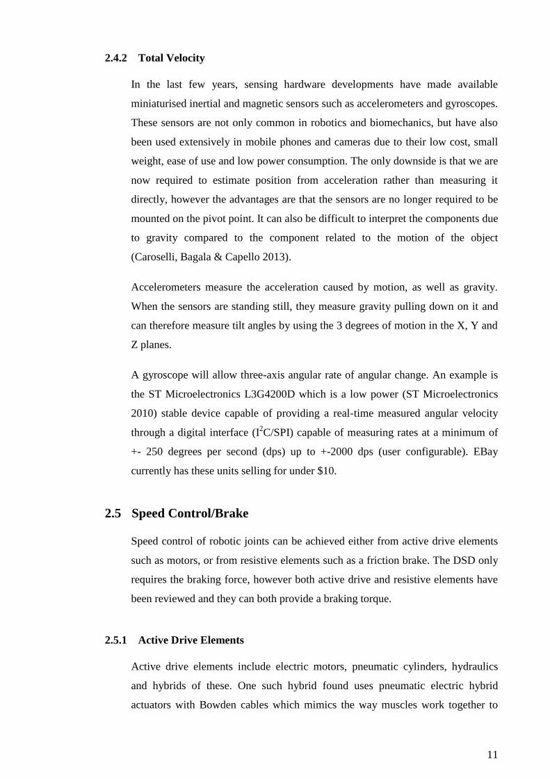
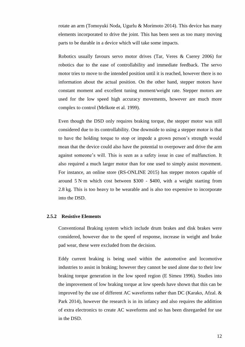

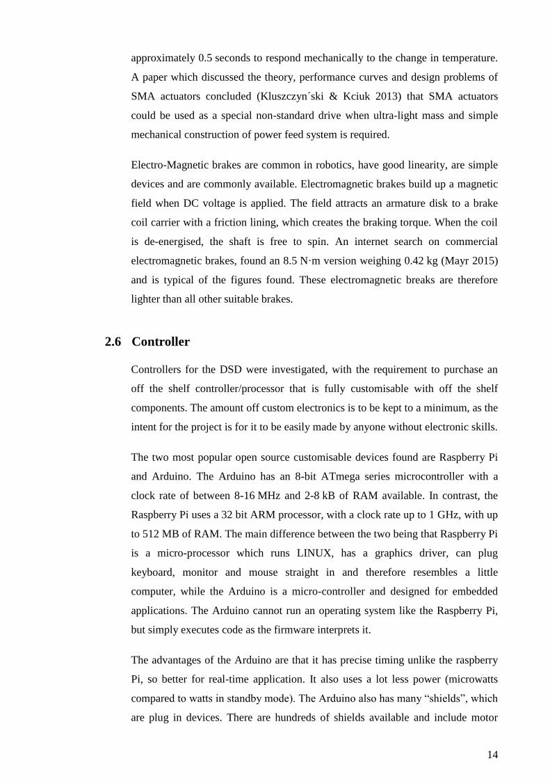


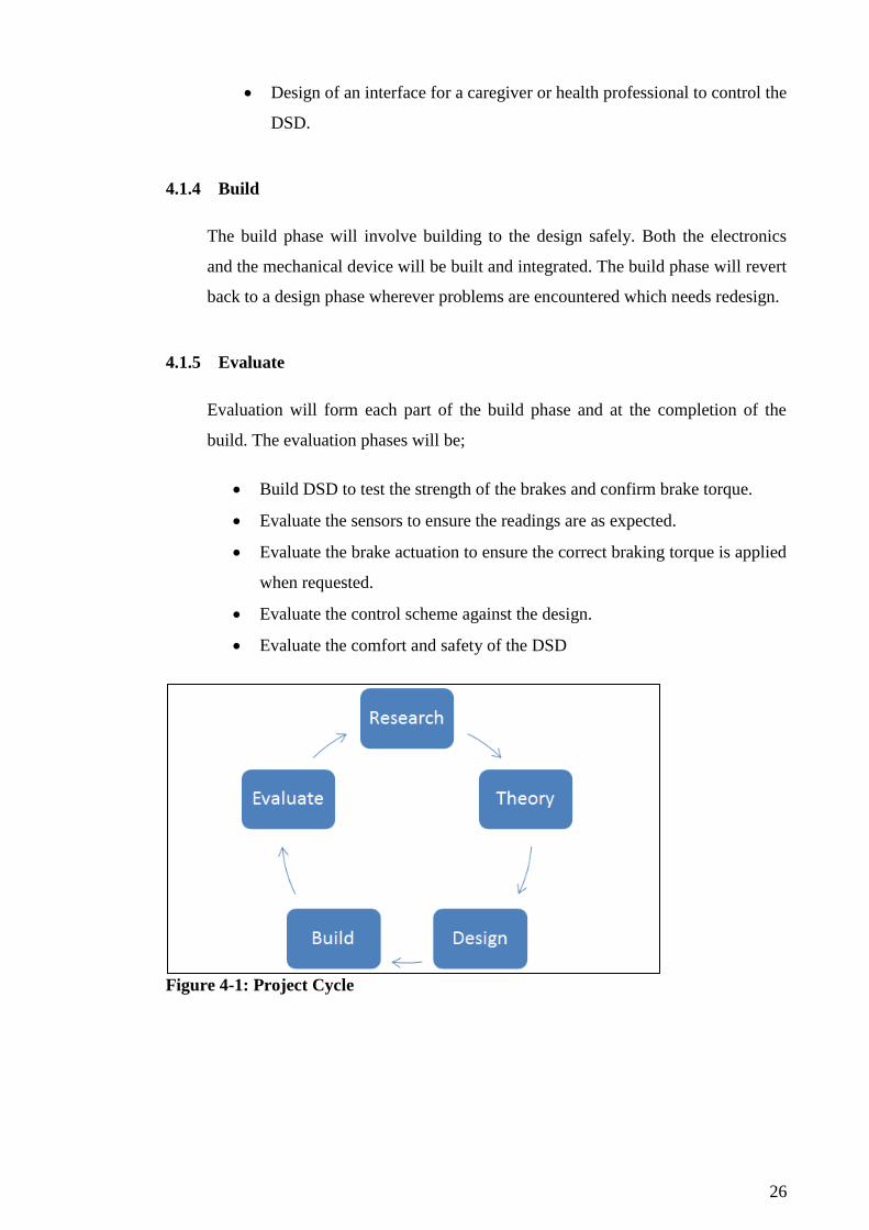

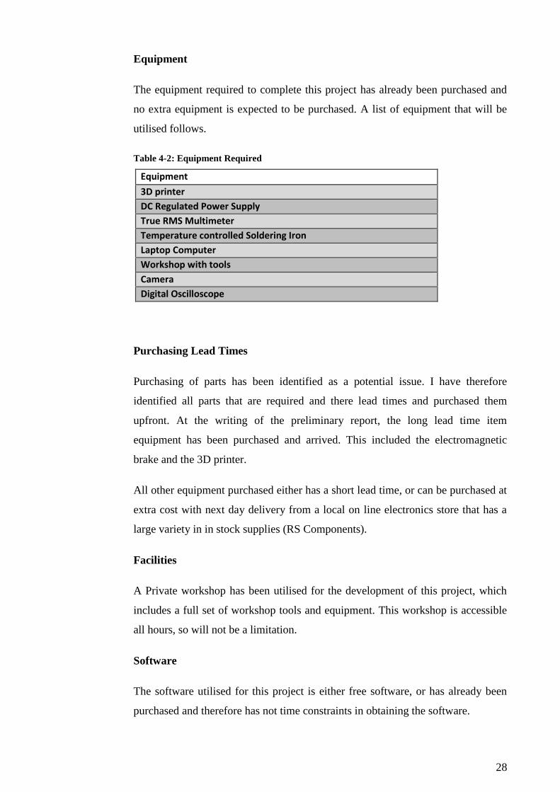


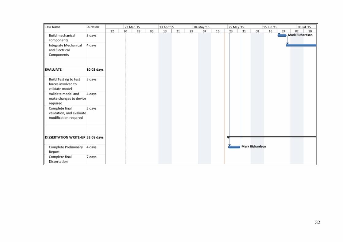

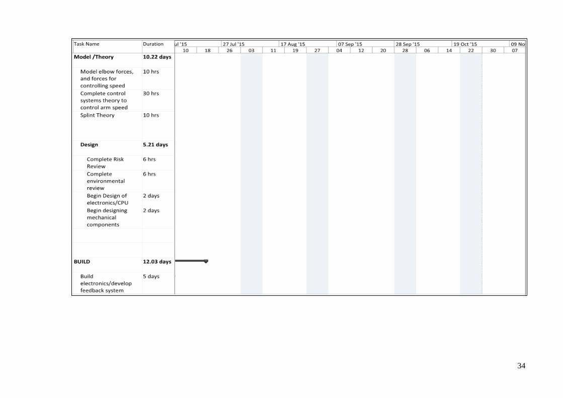


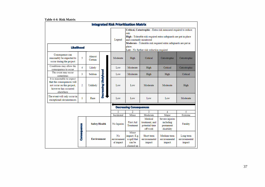


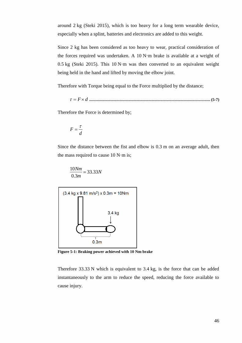


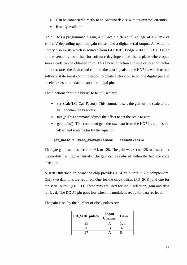


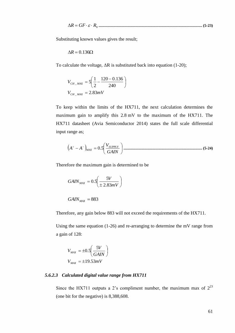


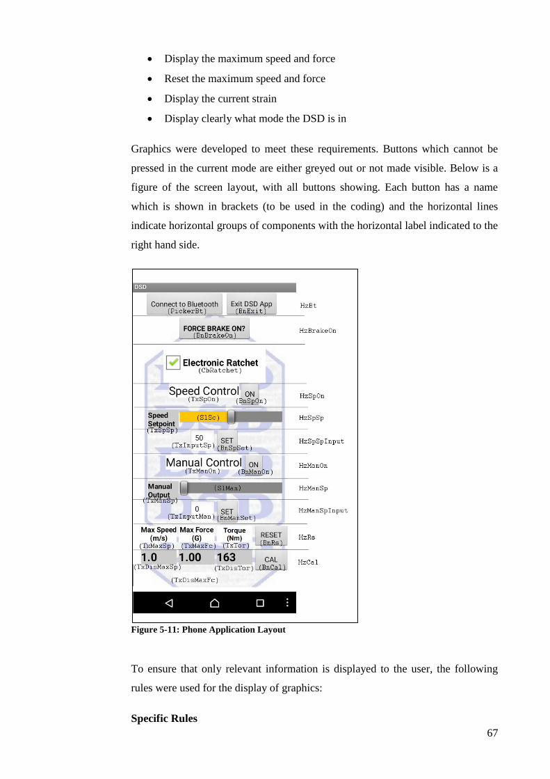


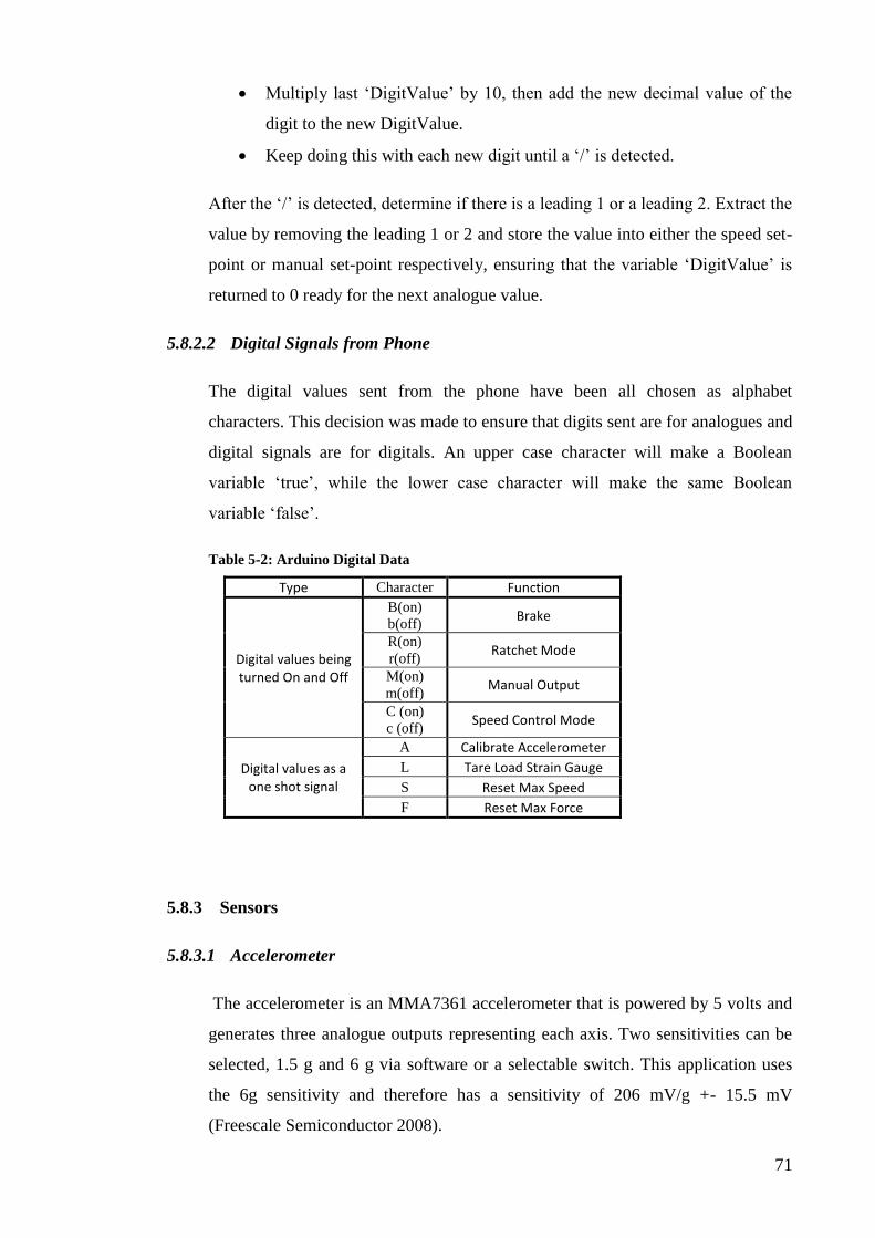


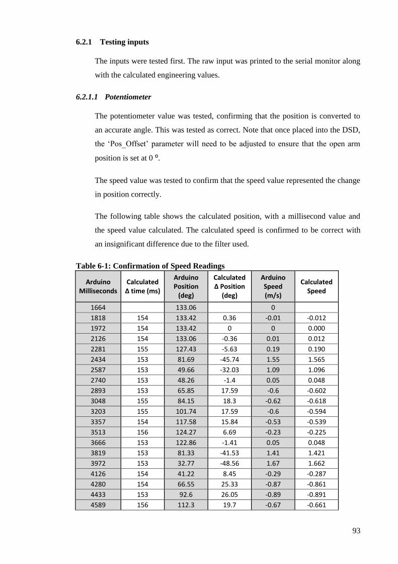


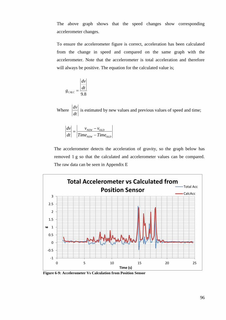
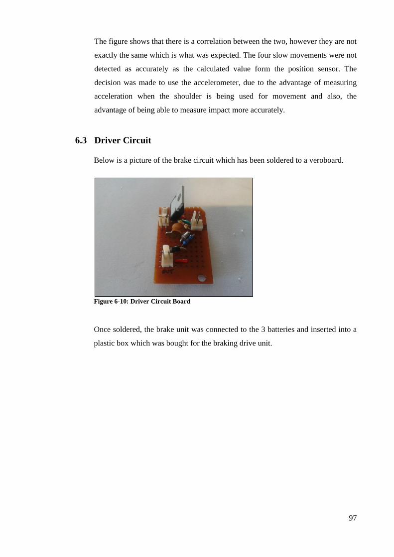


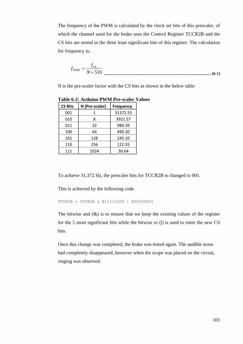

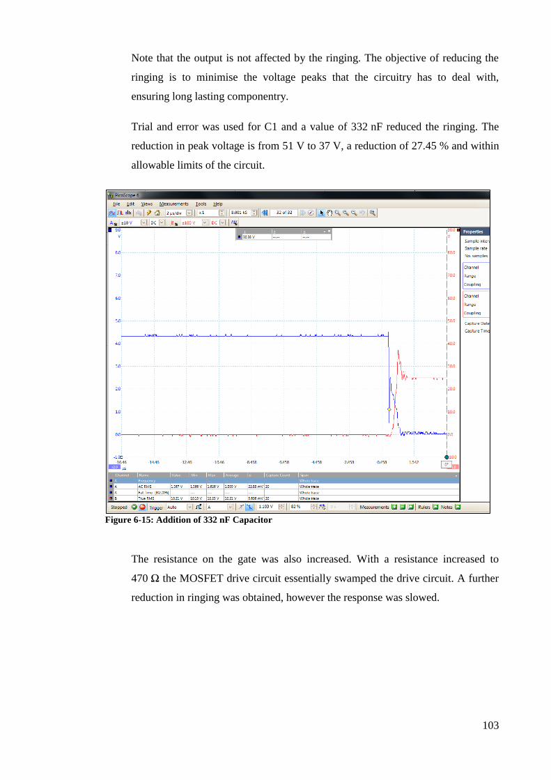


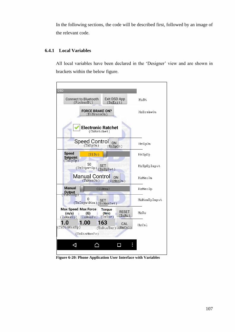

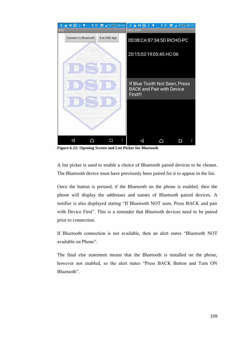


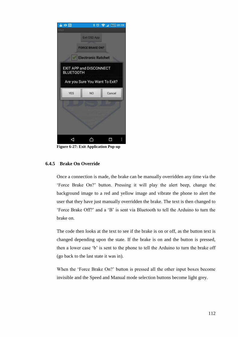


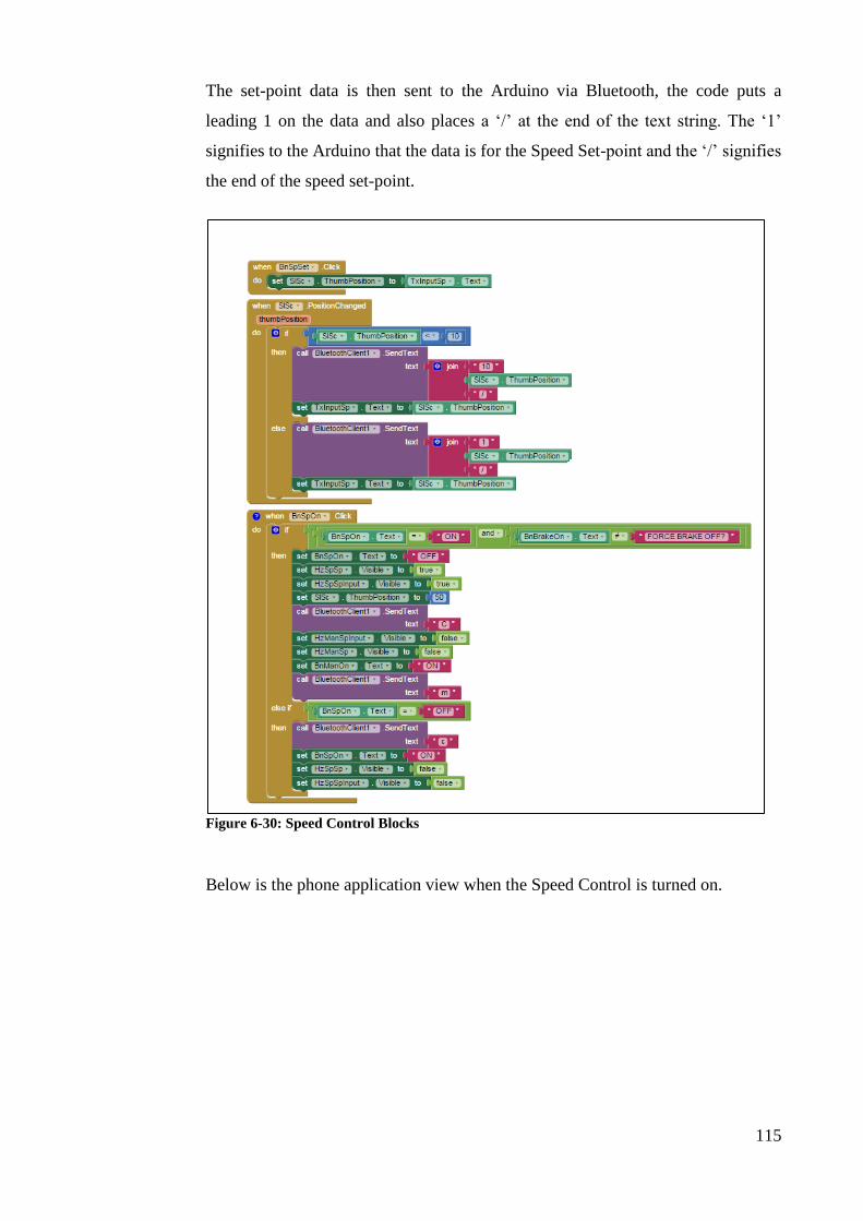
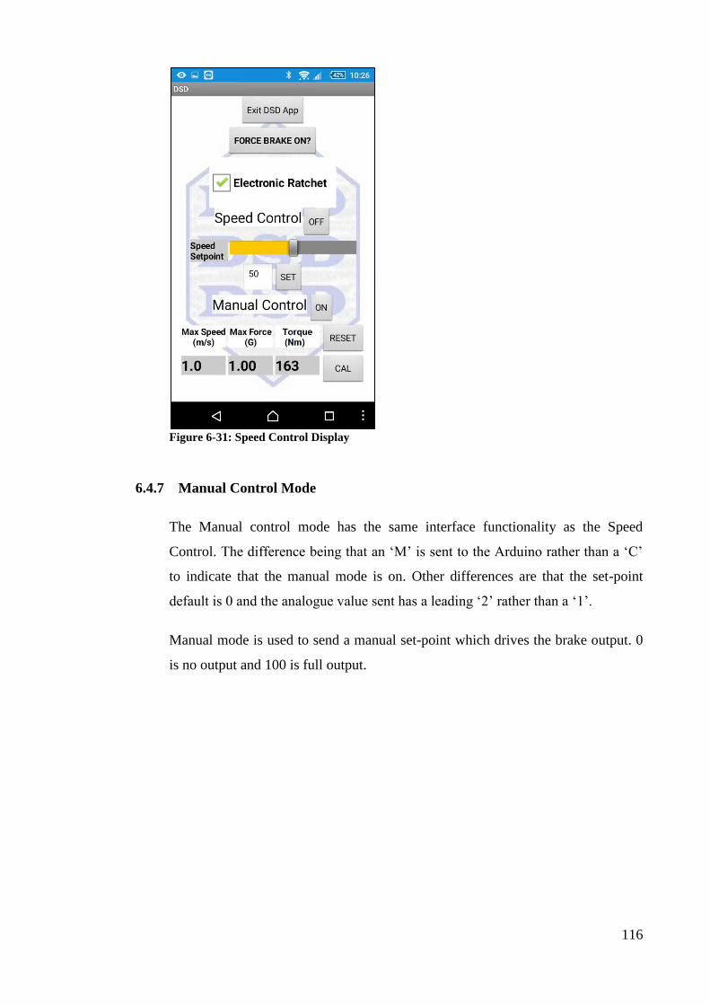


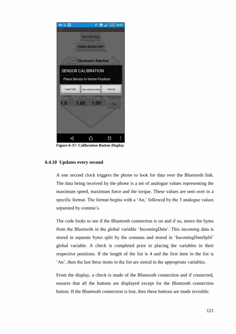


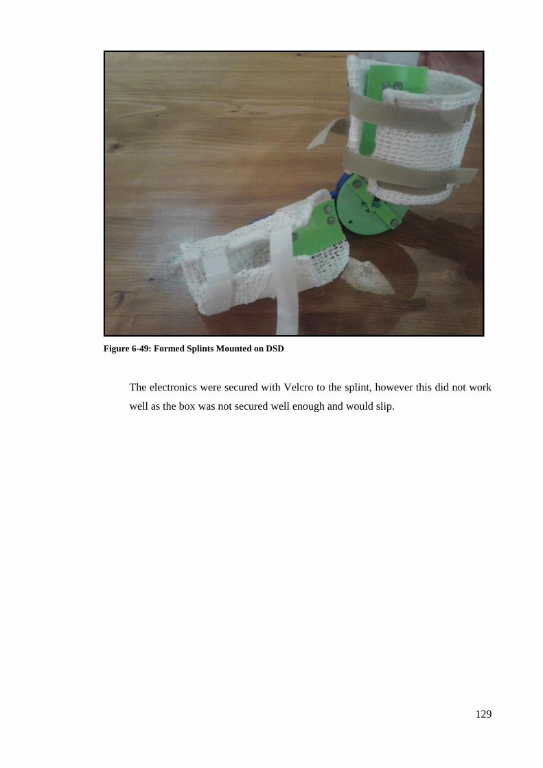

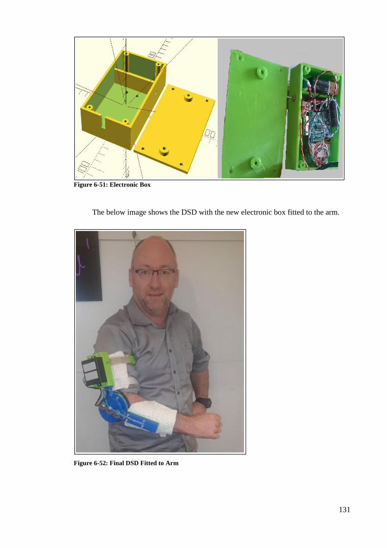


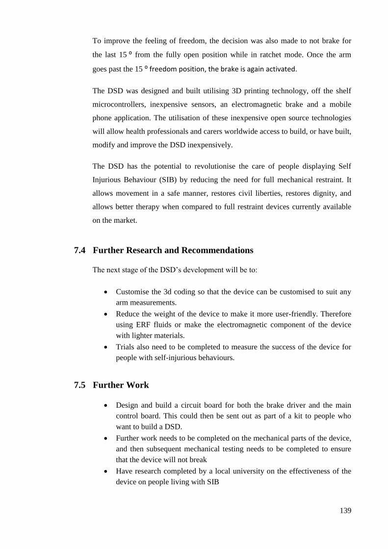


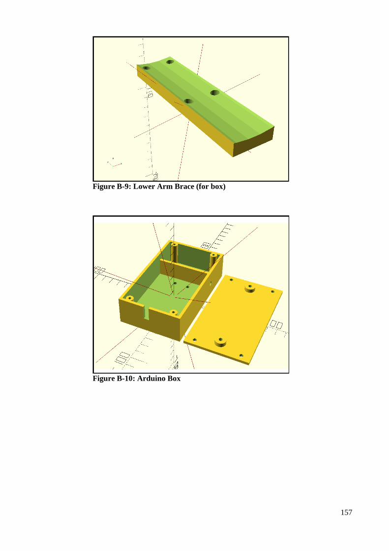


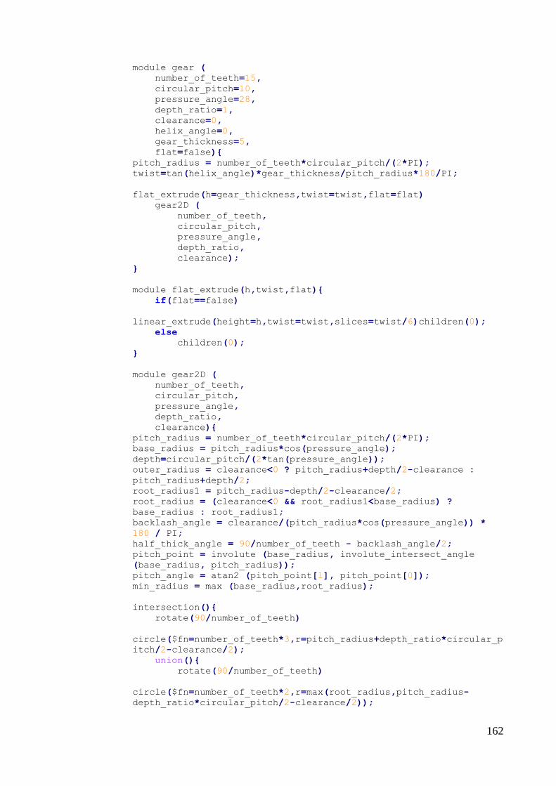
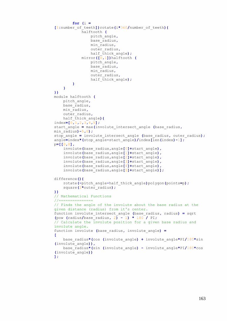


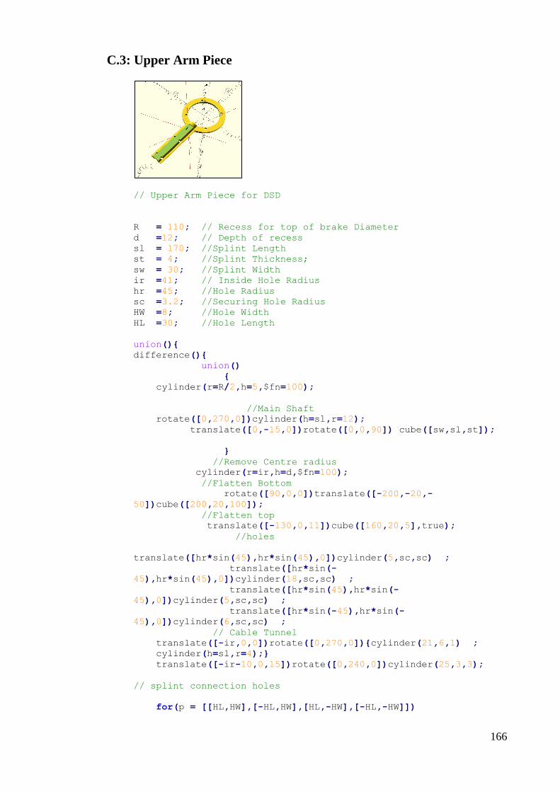

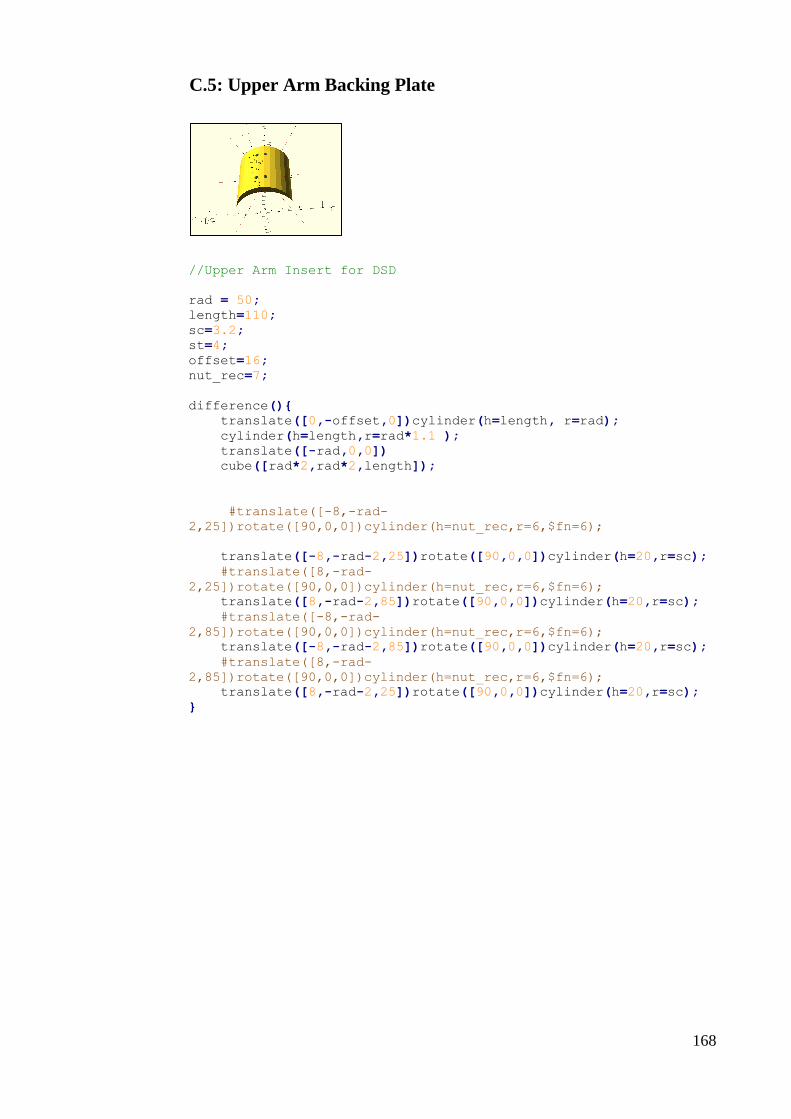

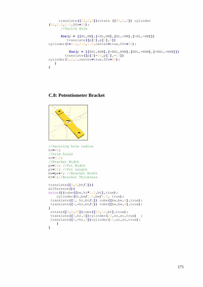


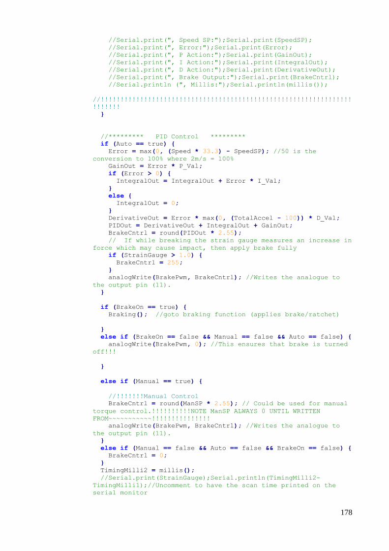
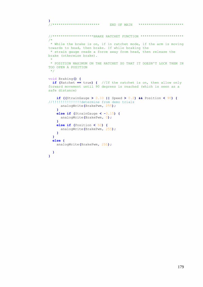


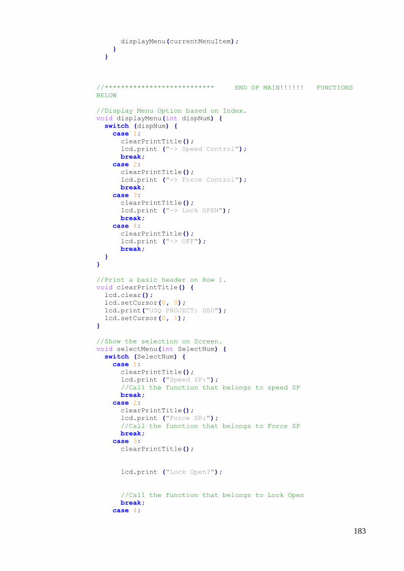


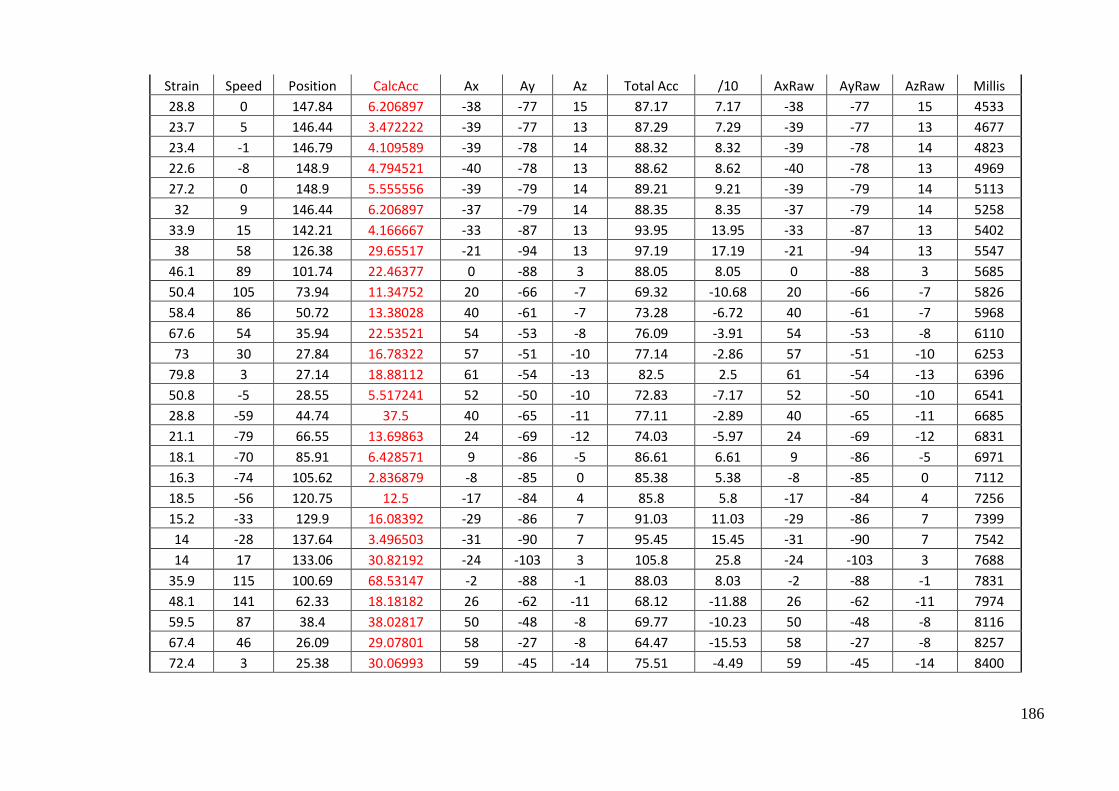


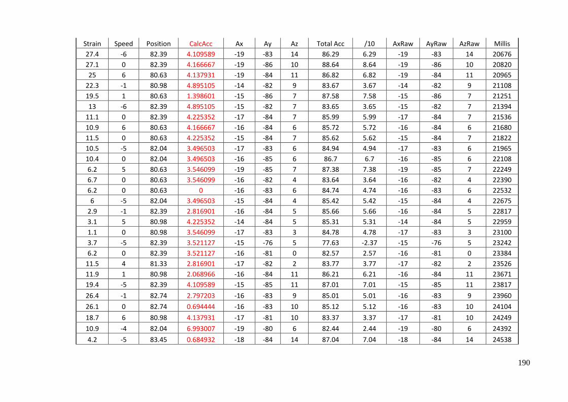
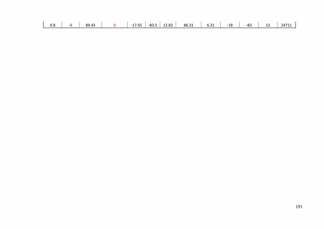
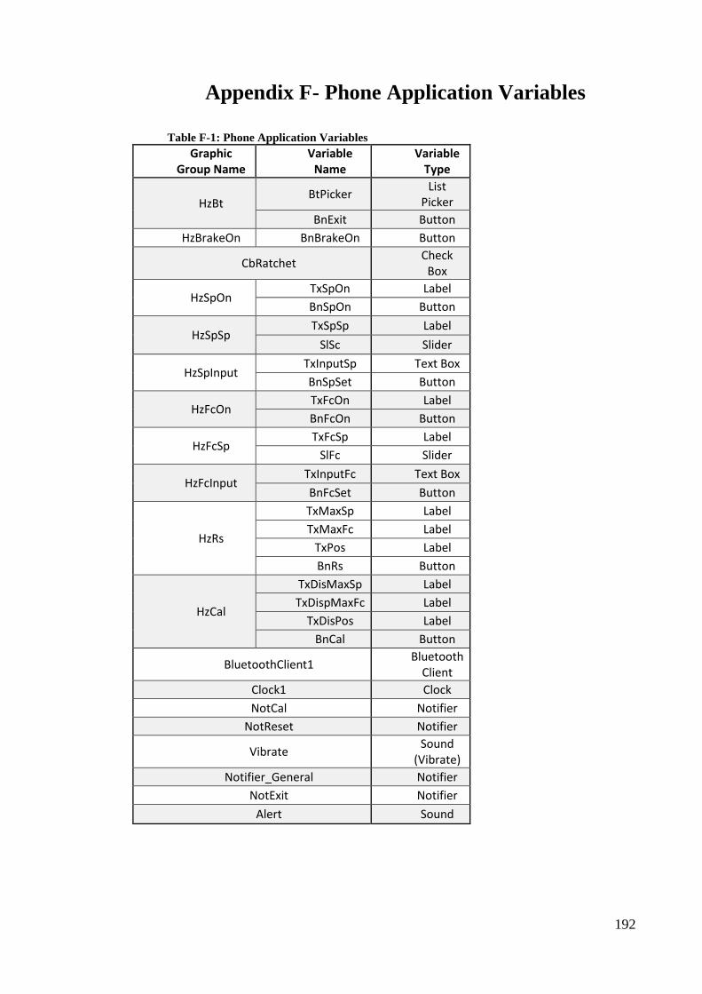


![There and back again - USQ ePrintseprints.usq.edu.au/8331/1/Moffatt_Joomla_History_Slides.pdfA history of access control 2 About Me Sam Moffatt [ pasamio ] Development Co-ordinator,](https://static.documents.pub/doc/80x56/5f3d01e6f8652946ba785c2a/there-and-back-again-usq-a-history-of-access-control-2-about-me-sam-moffatt-.jpg)


![2014 OPEN ACCESS energies - USQ ePrintseprints.usq.edu.au/25172/1/Al-lwayzy_Yusaf_Al-Juboori_Energies_v7… · fuel demand [1]. Therefore, exploring other potential sources for alternative](https://static.documents.pub/doc/80x56/5eb7e7791205a14136184b8f/2014-open-access-energies-usq-fuel-demand-1-therefore-exploring-other-potential.jpg)