194
Automatic Test System Critical Interfaces Report Release 1 9/30/96

Automatic Test SystemCritical Interfaces Report
Release 19/30/96

ATS Critical Interfaces Report
TABLE OF CONTENTS1. Executive Summary................................................................................................................................1.1 Statement of the Problem........................................................................................................................1.2 The Critical Interfaces Project.................................................................................................................1.3 The Critical Interfaces.............................................................................................................................
1.3.1 Hardware.........................................................................................................................................1.3.2 Software..........................................................................................................................................
1.4 Selected Critical Interface Candidates.....................................................................................................1.4.1 Hardware.........................................................................................................................................1.4.2 Software..........................................................................................................................................
1.5 Recommendations for Further Research..................................................................................................1.5.1 Hardware.........................................................................................................................................1.5.2 Software..........................................................................................................................................
2. Introduction.............................................................................................................................................2.1 Purpose...................................................................................................................................................2.2 Background.............................................................................................................................................3. Programmatics........................................................................................................................................3.1 Organization...........................................................................................................................................3.2 Objectives...............................................................................................................................................3.3 Process....................................................................................................................................................3.4 Scope......................................................................................................................................................3.5 Technical Approach................................................................................................................................4. Hardware.................................................................................................................................................4.1 Hardware Interfaces................................................................................................................................4.2 Hardware Decomposition........................................................................................................................4.3 Definitions of Potentially Critical Hardware Interfaces............................................................................
4.3.1 Computer Asset Controller Interface................................................................................................4.3.2 Computer to External Environments Interface.................................................................................4.3.3 Host Computer Interface..................................................................................................................4.3.4 Instrument Control Bus Interface.....................................................................................................4.3.5 Receiver/Fixture Interface...............................................................................................................4.3.6 Switching Matrix Interface..............................................................................................................4.3.7 Hardware Interface Criticality Evaluation........................................................................................
4.4 Recommended Hardware Critical Interfaces............................................................................................4.4.1 Computer to External Environments Interface.................................................................................
4.4.1.1 Computer to External Environments Candidates.......................................................................4.4.1.2 Computer to External Environments Recommendations and Rationale.....................................
4.4.2 Switching Matrix Interface..............................................................................................................4.4.2.1 Decomposition.........................................................................................................................4.4.2.2 Requirements and Issues Considered........................................................................................4.4.2.3 General Requirements..............................................................................................................4.4.2.4 Current Government ATE Requirements..................................................................................
4.4.2.4.1 Programmable DC Power Supplies....................................................................................4.4.2.4.2 Programmable DC Loads..................................................................................................4.4.2.4.3 AC Power Supply Requirements.......................................................................................4.4.2.4.4 Summary Power Supply Requirements..............................................................................4.4.2.4.5 Digital I/O Capabilities.....................................................................................................4.4.2.4.6 Analog Instrumentation Requirements..............................................................................4.4.2.4.7 Analog Instrumentation Requirements Summary...............................................................4.4.2.4.8 Power Switch Matrix Requirements..................................................................................
Page i

ATS Critical Interfaces Report
4.4.2.4.9 Low Frequency Switch Matrix Requirements....................................................................4.4.2.4.10 Performance Switch Matrix Requirements......................................................................4.4.2.4.11 ATS Summary Core Capability.......................................................................................4.4.2.4.12 Connector Module Requirements Summary....................................................................
4.4.2.5 Switching Matrix Recommendations and Rationale..................................................................4.4.2.5.1 General.............................................................................................................................4.4.2.5.2 Switching Matrix Building Block Configuration...............................................................
4.4.3 Receiver/Fixture Interface...............................................................................................................4.4.3.1 Decomposition.........................................................................................................................4.4.3.2 Subelement Review..................................................................................................................4.4.3.3 Requirements and Alternatives Considered...............................................................................
4.4.3.3.1 Receiver Trade-Offs..........................................................................................................4.4.3.3.2 Receiver - Resource Interface Alternatives........................................................................
4.4.3.3.2.1 Receiver Mechanisms................................................................................................4.4.3.3.2.2 Receiver Framework Design......................................................................................4.4.3.3.2.3 Receiver Mechanical Advantage................................................................................
4.4.3.3.3 Fixture Product Design Alternatives..................................................................................4.4.3.3.4 General Requirements.......................................................................................................
4.4.3.3.4.1 Design General Objectives........................................................................................4.4.3.3.4.2 Design Performance Objectives.................................................................................4.4.3.3.4.3 Receiver/Fixture Building Block I/O Requirements...................................................4.4.3.3.4.4 Receiver/Fixture Connector Requirements.................................................................
4.4.3.4 Receiver/Fixture Recommendations and Rationale...................................................................4.4.3.4.1 Subelement Review..........................................................................................................4.4.3.4.2 Connector Review and Weighting Process........................................................................
4.4.3.4.2.1 Connector/Module Review Candidates......................................................................4.4.3.4.2.2 Connector and Contacts.............................................................................................4.4.3.4.2.3 Eurocard DIN Standard.............................................................................................4.4.3.4.2.4 Mixed Low/High Power Contacts and Connector Module..........................................4.4.3.4.2.5 Low RF Coax Commercial Contacts and Connector Module.....................................4.4.3.4.2.6 High Performance RF Coax Contacts and Connector Module....................................
4.4.3.5 Receiver/Fixture Mechanism Review and Weighting Process...................................................4.4.3.5.1 Introduction......................................................................................................................4.4.3.5.2 Receiver/Fixture Mechanism Candidates..........................................................................
4.4.3.5.2.1 Critical Issues of the Selection Process......................................................................4.4.3.5.2.2 Level of Applicability................................................................................................4.4.3.5.2.3 Open System Architecture.........................................................................................4.4.3.5.2.4 Scaleability................................................................................................................
4.4.3.5.3 Receiver/Fixture Mechanism Results................................................................................4.4.3.5.4 Receiver/Fixture Mechanisms Long Term Solution...........................................................4.4.3.5.5 Receiver/Fixture Mechanisms Short Term Solution...........................................................
4.4.3.6 Fixture Enclosures Review and Weighting Process...................................................................4.4.3.6.1 Fixture Enclosure and Internal Packaging Structure Review Candidates............................4.4.3.6.2 Fixture Enclosures............................................................................................................4.4.3.6.3 Internal Packaging Review and Weighting Process...........................................................
4.4.3.7 Receiver/Fixture Pin Map Evaluation.......................................................................................5. Software...................................................................................................................................................5.1 Software Decomposition.........................................................................................................................5.2 Run Time Interfaces................................................................................................................................
5.2.1 Data Networking.............................................................................................................................5.2.1.1 Data Networking Candidates....................................................................................................5.2.1.2 Data Networking Recommendations and Rationale..................................................................
5.2.2 Instrument Communication..............................................................................................................5.2.2.1 Generic Instrument Classes......................................................................................................
Page ii

ATS Critical Interfaces Report
5.2.2.1.1 Generic Instrument Classes Candidates.............................................................................5.2.2.1.2 Generic Instrument Classes Recommendations and Rationale...........................................
5.2.2.2 Instrument Command Language...............................................................................................5.2.2.2.1 Instrument Command Language Candidates......................................................................
5.2.2.2.1.1 Control Interface Intermediate Language...................................................................5.2.2.2.1.2 Standard Commands for Programmable Instruments..................................................
5.2.2.2.2 Instrument Command Language Recommendations and Rationale....................................5.2.2.3 Instrument Communication Manager........................................................................................
5.2.2.3.1 Instrument Communication Manager Candidates..............................................................5.2.2.3.1.1 Virtual Instrument Software Architecture..................................................................5.2.2.3.1.2 IEEE P1226.5............................................................................................................
5.2.2.3.2 Instrument Communication Manager Recommendations and Rationale............................5.2.2.4 Instrument Driver API..............................................................................................................
5.2.2.4.1 Instrument Driver API Candidates.....................................................................................5.2.2.4.1.1 VPP-3........................................................................................................................5.2.2.4.1.2 IEEE P1226.4............................................................................................................5.2.2.4.1.3 ATLAS Intermediate Language.................................................................................5.2.2.4.1.4 Test Resource Information Model..............................................................................5.2.2.4.1.5 Instrument Command Languages...............................................................................5.2.2.4.1.6 Driver API plus Instrument Command Languages Hybrids........................................
5.2.2.4.2 Instrument Driver API Recommendations and Rationale...................................................5.2.3 Software and Software Coordination Interfaces................................................................................
5.2.3.1 Diagnostic Processing...............................................................................................................5.2.3.1.1 Diagnostic Processing Candidates.....................................................................................5.2.3.1.2 Diagnostic Processing Recommendations and Rationale...................................................
5.2.3.2 Framework...............................................................................................................................5.2.3.2.1 Framework Candidates......................................................................................................5.2.3.2.2 Framework Recommendations and Rationale....................................................................
5.2.3.3 Multimedia Formats.................................................................................................................5.2.3.3.1 Multimedia Formats Candidates........................................................................................
5.2.3.3.1.1 Commercial and Proprietary Formats.........................................................................5.2.3.3.1.2 World Wide Web Formats.........................................................................................5.2.3.3.1.3 Standards Based Formats...........................................................................................
5.2.3.3.2 Multimedia Formats Recommendations and Rationale......................................................5.2.3.4 Run Time Services...................................................................................................................
5.2.3.4.1 Run Time Services Candidates..........................................................................................5.2.3.4.1.1 ATLAS Intermediate Language.................................................................................5.2.3.4.1.2 ABBET Standards Related to Run Time Services......................................................
5.2.3.4.2 Run Time Services Recommendations and Rationale........................................................5.2.3.5 Test Program to Operating System...........................................................................................
5.2.3.5.1 Test Program to Operating System Candidates..................................................................5.2.3.5.2 Test Program to Operating System Recommendations and Rationale................................
5.3 Development Interfaces...........................................................................................................................5.3.1 Application Development Environments..........................................................................................
5.3.1.1 Text-based Application Development Environments................................................................5.3.1.2 Graphical Application Development Environments..................................................................5.3.1.3 Hybrid Application Development Environments.......................................................................5.3.1.4 Desirable Characteristics in an Application Development Environments..................................5.3.1.5 Application Development Environments Candidates................................................................5.3.1.6 Application Development Environments Recommendations and Rationale...............................
5.3.2 Digital Test Data Formats................................................................................................................5.3.2.1 Logic Values............................................................................................................................5.3.2.2 Patterns....................................................................................................................................5.3.2.3 Relevancy................................................................................................................................
Page iii
ATS Critical Interfaces Report
5.3.2.4 Timing.....................................................................................................................................5.3.2.5 Levels......................................................................................................................................5.3.2.6 Compression............................................................................................................................5.3.2.7 Diagnostics...............................................................................................................................5.3.2.8 Models.....................................................................................................................................5.3.2.9 Digital Test Data Format Candidates........................................................................................
5.3.2.9.1 Commercial Formats.........................................................................................................5.3.2.9.1.1 Standard Event Format..............................................................................................5.3.2.9.1.2 Waveform Generation Language...............................................................................5.3.2.9.1.3 LSRTAP (SDF).........................................................................................................
5.3.2.9.2 Standards-based Formats...................................................................................................5.3.2.9.2.1 IEEE Std 1029.1-1989...............................................................................................5.3.2.9.2.2 IEEE P1445 Digital Test Interchange Format............................................................5.3.2.9.2.3 IEEE P1450 Standard Test Interchange Language.....................................................
5.3.2.10 Digital Test Data Format Recommendations and Rationale....................................................5.3.3 ATE and UUT Information Interfaces..............................................................................................
5.3.3.1 Adapter Function and Parametric Data.....................................................................................5.3.3.2 ATE Instrument Function and Parametric Data.........................................................................5.3.3.3 ATE Switching Function and Parametric Data..........................................................................5.3.3.4 UUT Test Requirements...........................................................................................................5.3.3.5 Information Interface Candidates..............................................................................................
5.3.3.5.1 Documentation..................................................................................................................5.3.3.5.2 ATLAS Compiler (e.g., TYX, ARINC SMART) Databases..............................................5.3.3.5.3 ATLAS Language.............................................................................................................5.3.3.5.4 CAD/CAM Formats..........................................................................................................5.3.3.5.5 Test Resource Information Model.....................................................................................5.3.3.5.6 VPP-5 Expanded to Include Parametric Data....................................................................
5.3.3.6 Information Interface Recommendations and Rationale............................................................5.3.4 TPS Documentation.........................................................................................................................
5.3.4.1 TPS Documentation Candidates...............................................................................................5.3.4.2 TPS Documentation Recommendations and Rationale..............................................................
6. Recommendations for Further Research................................................................................................6.1 Hardware Issues......................................................................................................................................6.2 Software Issues.......................................................................................................................................
6.2.1 AFP, IFP, and SFP Interfaces...........................................................................................................6.2.2 Diagnostic Processing......................................................................................................................6.2.3 Generic Instrument Classes..............................................................................................................6.2.4 Run Time Services..........................................................................................................................6.2.5 Test Program Documentation...........................................................................................................6.2.6 UUT Test Requirements..................................................................................................................6.2.7 Convergence of Information Interfaces............................................................................................
7. Summary.................................................................................................................................................7.1 Conclusions Dealing with Hardware Interfaces........................................................................................7.2 Conclusions Dealing with Software Interfaces.........................................................................................8. Perry Memorandum...............................................................................................................................9. Glossary...................................................................................................................................................10. Acronyms and Abbreviations................................................................................................................11. Critical Interfaces Working Group Members......................................................................................
Page iv
ATS Critical Interfaces Report
LIST OF TABLESTable 1 Hardware Critical Interfaces............................................................................................................Table 2 Software Critical Interfaces.............................................................................................................Table 3 Hardware Critical Interface Candidates...........................................................................................Table 4 Software Critical Interface Candidates.............................................................................................Table 5 Critical Interfaces Standardization Guidelines.................................................................................Table 6 Hardware Interfaces Summary Matrix.............................................................................................Table 7 DoD ATS Programmable DC Power Supply Configurations............................................................Table 8 DoD ATS Programmable DC Load Configurations..........................................................................Table 9 DoD ATS AC Power Supply Configurations...................................................................................Table 10 DoD ATS Digital I/O Capabilities.................................................................................................Table 11 DoD ATS Analog Instrumentation Descriptions............................................................................Table 12 DoD ATS Analog Instrumentation Requirements..........................................................................Table 13 DoD ATS Power Switch Matrix Requirements..............................................................................Table 14 DoD ATS Low Frequency Switch Matrix Requirements................................................................Table 15 Performance Switch Matrix Requirements.....................................................................................Table 16 DoD ATS Connector Module Requirements..................................................................................Table 17 Worst Case - High End Requirements............................................................................................Table 18 Typical - Mid Range Requirements...............................................................................................Table 19 Basic - Low End Requirements.....................................................................................................Table 20 Signal Contact Requirement..........................................................................................................Table 21 High Power Contact Requirement..................................................................................................Table 22 Low Power Contact Requirement..................................................................................................Table 23 Low RF Coax Contact Requirement..............................................................................................Table 24 High RF Coax Contact Requirement..............................................................................................Table 25 Receiver/Fixture Connector Product Design Comparison...............................................................Table 26 Eurocard DIN Comparison - Part 1................................................................................................Table 27 Eurocard DIN Comparison - Part 2................................................................................................Table 28 Receiver/Fixture Mechanism Product Design Review....................................................................Table 29 Fixture Internal Packaging Product Review Comparison Chart......................................................Table 30 Possible Pin Map Configuration and Related Test Requirements for DoD ATS.............................Table 31 Critical Interfaces Standardization Guidelines...............................................................................Table 32 Hardware Critical Interfaces (Summary)........................................................................................Table 33 Software Critical Interfaces (Summary).........................................................................................
Page v
ATS Critical Interfaces Report
LIST OF FIGURESFigure 1 ATS Hardware Interfaces...............................................................................................................Figure 2 TPS Development Interfaces..........................................................................................................Figure 3 TPS Run Time Interfaces...............................................................................................................Figure 4 Example ATS Interfaces................................................................................................................Figure 5 CIWG Organization.......................................................................................................................Figure 6 CIWG Process................................................................................................................................Figure 7 Generic ATS Architecture..............................................................................................................Figure 8 CASS Hardware Architecture.........................................................................................................Figure 9 CASS Software Architecture..........................................................................................................Figure 10 IFTE Hardware Interfaces............................................................................................................Figure 11 IFTE Software Interfaces..............................................................................................................Figure 12 ATS Generic Hardware Interfaces................................................................................................Figure 13 Test Program Isolation From Host Computer................................................................................Figure 14 Re-host of a TPS..........................................................................................................................Figure 15 Switching Matrix Product Designs................................................................................................Figure 16 Sample Switch Matrix Configuration #1.......................................................................................Figure 17 Sample Switch Matrix Configuration #2.......................................................................................Figure 18 Example Receiver/Fixture ATS Interfaces....................................................................................Figure 19 Receiver/Fixture Basic Elements..................................................................................................Figure 20 Receiver/Fixture Subcomponents.................................................................................................Figure 21 Receiver Interfacing Approaches..................................................................................................Figure 22 Receiver Subelements..................................................................................................................Figure 23 Example Mechanical Interface Receivers.....................................................................................Figure 24 Fixture Basic Design....................................................................................................................Figure 25 Connector/Module Configurations................................................................................................Figure 26 Signal Connector/Module Detail..................................................................................................Figure 27 Eurocard DIN Receiver Connector/Module Design Specification.................................................Figure 28 Eurocard DIN Fixture Connector/Module Design Specification....................................................Figure 29 Mixed Low/High Power Contacts and Connector Module Design.................................................Figure 30 Low Performance RF Coax Commercial Connector Module and Contacts....................................Figure 31 High RF Coax Contacts and Connector Module...........................................................................Figure 32 Receiver/Fixture Mechanism Design Specification Configuration................................................Figure 33 Possible Receiver/Fixture Pin Map Configuration.........................................................................Figure 34 TPS Run Time View of Potential Critical Interfaces.....................................................................Figure 35 TPS Development Potential Critical Interfaces.............................................................................Figure 36 VXIplug&play Instrument Driver Diagram..................................................................................Figure 37 System Communication Interfaces...............................................................................................Figure 38 Product Test Information Flow.....................................................................................................
Page vi

1Executive Summary
1.1Statement of the ProblemFrom 1980 to 1992, the U.S. Department of Defense (DoD) investment in depot and factory Automatic Test Systems (ATS) exceeded $35 billion with an additional $15 billion for associated support. Most of this test capability was acquired as part of individual weapon system procurements. This led to a proliferation of different custom equipment types with unique interfaces and made the DoD appear to be a variety of separate customers.Recent policy decisions have changed the direction of the DoD on the purchase of test equipment.
· DoD ATS Policy, USD (A&T) - 15 March 1996, and DoD Regulation 5000.2-R1 bring a cost effective approach to the acquisition of Automatic Test Equipment (ATE). This policy requires hardware and software needs for depot and intermediate-level applications to be met using DoD designated families and commercial equipment with defined interfaces and requires the management of ATS as a separate commodity through a DoD Executive Agent Office (EAO)
· Secretary of Defense Memorandum on Specifications and Standards - 29 June 1994, directs that DoD procurements will be made first by performance definition, second by commercial standards, and finally (and only with waiver) by military standards
The DoD Regulation 5000.2-R ATS Policy states: “ATS capabilities shall be defined through critical hardware and software elements.” The policy does not currently define these critical elements. The Critical Interfaces Project was created to define critical ATS elements.
1.2The Critical Interfaces ProjectThe Factory-to-Field Integration of Defense Test Systems Project (commonly referred to as the Critical Interfaces Project) was started in the latter part of 1995. The Critical Interfaces Working Group (CIWG) within the Joint-Service ATS Research and Development Integrated Product Team (ARI) was established to perform the project. The ATS EAO has provided project management and coordination among the Air Force, Army, Marine Corps, and Navy participants. In addition, many industry representatives have participated.The objective of the Critical Interfaces Project is to demonstrate the feasibility of reducing the cost to re-host Test Program Sets (TPSs) and increase the interoperability of TPS software among the military services by using standardized interfaces. Interfaces that
1 DoD Regulation 5000.2-R, dated 15 March 1996. “DoD Automated Test System (ATS) families or COTS components that meet defined ATS capabilities shall be used to meet all acquisition needs for automatic test equipment hardware and software. ATS capabilities shall be defined through critical hardware and software elements. The introduction of unique types of ATS into the DoD field, depot, and manufacturing operations shall be minimized.”
Page 1
offer the potential to achieve this objective are deemed critical. Potential savings will be quantified through demonstration.The CIWG developed a list of Critical Interfaces (CIs) and will demonstrate the use of these defined CIs on common testers. The three testers selected for demonstration purposes are the defense-designated tester families, the Consolidated Automated Support System (CASS) and the Integrated Family of Test Equipment (IFTE), and a commercial tester, the L300-Series from Teradyne. The interfaces considered are based upon open commercial standards, defacto standards, and DoD tester architectures including the CASS, IFTE, and the Marine Corps Automatic Test Equipment System (MCATES).A primary deliverable product from the CI project is this document setting forth the CI definitions. This document is intended to be used by DoD acquisition programs and maintained by the ATS EAO. This document will aid in satisfying the requirements of DoD Regulation 5000.2-R and assist convergence in migration plans for the DoD designated tester families.
1.3The Critical Interfaces
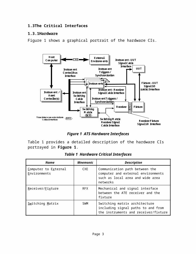
1.3.1HardwareFigure 1 shows a graphical portrait of the hardware CIs.
Hardware Interfaces
Receiver Fixture
Instruments
Switching MatrixReceiver SignalCable Interface
Receiver-FixtureSignal I/O Interface
Instrument - UUTSignal Cable
InterfaceInstrumentTriggers /
Synchronization
InstrumentControl Bus
Interface
Fixture - UUTSignal I/O
(cable) Interface
UUT
ExternalEnvironments
Instrument - ReceiverSignal Cable Interface
RFX
SWM
SwitchingMatrix
Instrument Triggers /Synchronization
Instrument /Asset
Controller(s)
HostComputer CXE
RFXThree letter mnemonics indicateCritical Interfaces
InstrumentSwitching
CableInterface
ATS_HW_I Figure 1Figure 1 ATS Hardware Interfaces
Table 1 provides a detailed description of the hardware CIs portrayed in Figure 1.
Table 1 Hardware Critical Interfaces
Page 2

Name Mnemonic Description
Computer to External Environments
CXE Communication path between the computer and external environments such as local area and wide area networks
Receiver/Fixture RFX Mechanical and signal interface between the ATE receiver and the fixture
Switching Matrix SWM Switching matrix architecture including signal paths to and from the instruments and receiver/fixture
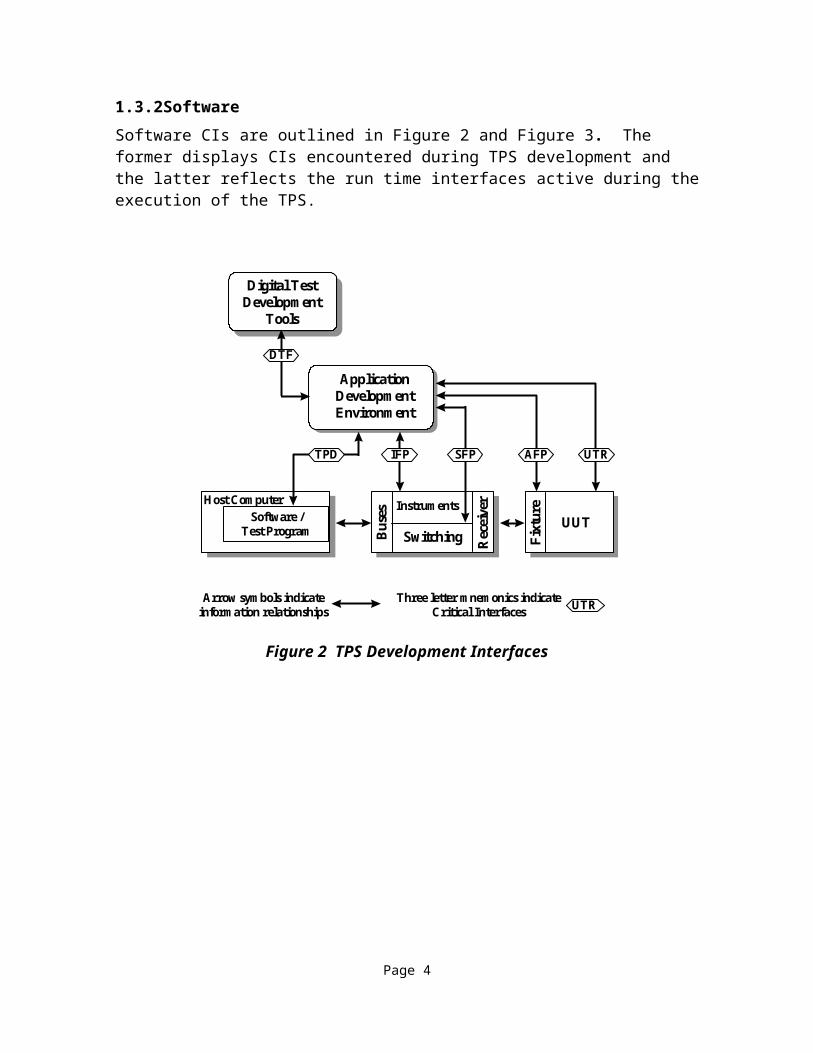
1.3.2SoftwareSoftware CIs are outlined in Figure 2 and Figure 3. The former displays CIs encountered during TPS development and the latter reflects the run time interfaces active during the execution of the TPS. TPS Development Interfaces
ApplicationDevelopmentEnvironment
Digital TestDevelopment
Tools
DTF
IFP SFP UTRAFP
Host ComputerSoftware /
Test Program Bus
es
Switching
Instruments
Rec
eive
r
Fixt
ure
UUT
Arrow symbols indicateinformation relationships UTRThree letter mnemonics indicate
Critical Interfaces
TPD
tps_dev_i Figure 2
Figure 2 TPS Development Interfaces
Page 3
TPS Run Time Interfaces
Application ExecutionEnvironment
InstrumentCommunication Stack
Inst
rum
ent
Dri
vers
Com
mun
icat
ion
Man
ager
Bus
Dri
versT
est
Proc
edur
eRun Time Services
Dia
gnos
ticPr
oces
sing
Fra
mew
ork
Operating System(s)
Computer(s)
MM
F
DIA
RTS
ICM
NE
T
FRM
Three letter mnemonics indicateCritical Interfaces
Host ComputerSoftware /
Test Program Bus
es
Switching
Instruments
Rec
eive
r
Fixt
ure
UUT
run_time_i Figure 3
DRV
TOS Gen
eric
Inst
rum
ent
Cla
sses
GIC
DR
V
Figure 3 TPS Run Time Interfaces
A description of the software CIs as shown in Figure 2 and Figure 3 are presented in Table2.
Table 2 Software Critical Interfaces
Name Mnemonic Description
Adapter Function and Parametric Data
AFP The information and formats used to define to the Application Development Environments the capabilities of the test fixture, how the capabilities are accessed, and the associated performance parameters
Diagnostic Processing DIA The interface protocol linking execution of a test with software diagnostic processes that analyze the significance of test results and suggest conclusions or additional actions that are required
Instrument Driver API DRV The Applications Programming Interface (API) through which instrument drivers accepts commands from and return results to Generic Instrument Classes (GIC).
Digital Test Format DTF The data formats used to convey the information used in conjunction with digital tests (e.g., vectors, fault dictionaries) from Digital Test Development Tools to the Application Development Environments.
Framework FRM A collection of system requirements, software protocols, and business rules (e.g., software installation) affecting the operation of test software with the underlying Host Computer and Host Operating System.
Page 4
Name Mnemonic Description
Generic Instrument Classes GIC The Applications Programming Interface (API) through which instrument drivers accept commands from and return results to the test procedure or run time services serving the Test Program.
Instrument Communication Manager
ICM The interface between the instrument drivers and the Communication Manager that supports communication with instruments independent of the bus or other protocol used (e.g., VXI, IEEE-488.2, RS-232).
Instrument Function and Parametric Data
IFP The information and formats used to define to the Application Development Environments the load, sense, and drive capabilities of the Instruments, how these capabilities are accessed, and the associated performance parameters.
Multimedia Formats MMF The formats used to convey hyperlinked text, audio, video and three-dimensional physical model information from Multimedia Authoring Tools to the Application Development Environments, Application Execution Environment, and Host Framework.
Network Protocols NET The protocol used to communicate with external environments over a local area or wide area network.
Run Time Services RTS The run time services needed by Test Programs not handled by the services supplied by the DRV, FRM, GIC and NET interfaces (e.g., error reporting, data logging).
Switch Function and Parametric Data
SFP The information and formats used to define to the Application Development Environments the interconnect capabilities of the Switch Matrix, how these capabilities are accessed, and the associated performance parameters.
Test Program to Operating System
TOS Calls to the Host Operating System made directly from the Test Program.
Test ProgramDocumentation
TPD Human-understandable representations of information about the TPS for use by the TPS maintainer.
UUT Test Requirements UTR The information and formats used to define to the Application Development Environments the load, sense, and drive capabilities that must be applied to the UUT to test it, including the minimum performance required for a successful test.
1.4Selected Critical Interface CandidatesPriority was given to formal or defacto commercial standards in selecting candidates for CIs. The effectiveness of these candidates will be evaluated during the demonstration phase. If the demonstration concludes that these candidates are effective at reducing the cost of a TPS re-host and increasing the interoperability of TPSs among the military services, they will be recommended by the ARI to the ATS EAO for inclusion into DoD acquisition guidelines.
Page 5

1.4.1HardwareThe hardware CIs and the selected candidates are presented in Table 3.
Table 3 Hardware Critical Interface Candidates
Critical Interface Mnemonic Candidate1. C omputer to External Environments CXE Any hardware capable of supporting TCP/IP2. R eceiver/Fixture RFX
3. Fixture Frame Mechanisms None4. Receiver Mechanisms None5. Contacts and Connector Module
6. Signal 200 position Eurocard DIN standard7. Low power None8. High power None9. Low RF None10. High RF None
11. Pin Map and connector/slot definition
None
12. Sw itching Matrix SWM13. Switch Module None
1.4.2SoftwareThe software CIs for which available candidates were selected are presented in Table 4.
Table 4 Software Critical Interface Candidates
Critical Interface Mnemonic CandidateAdapter Function and Parametric Data AFP NoneDiagnostic Processing DIA NoneInstrument Driver ADE
DRV VPP-32
The ADE shall communicate with instruments through VPP-3 instrument drivers
Digital Test Format DTF LSRTAP (SDF)Framework ADE
FRM VPP-22
The ADE shall be compatible with at least one framework in VPP-2. Cross platform compatibility is preferred.
Generic Instrument Classes GIC NoneInstrument Communication Manager ICM VPP-42
Instrument Function and Parametric Data IFP None
2 Candidates for three of the software critical interfaces (VPP-2, VPP-3, and VPP-4) are specifications from the VXIplug&play Systems Alliance, a widely supported industry group.
Page 6

Critical Interface Mnemonic CandidateMultimedia Formats MMF NoneNetwork Protocols NET TCP/IP (IAB STD 1)Run Time Services RTS NoneSwitch Function and Parametric Data SFP NoneTest Program to Operating System TOS Calls to the Host Operating System
prohibitedTest Program Documentation TPD DI-ATTS-80284A and DI-ATTS-80285A
(and DI-ATTS-80285 if need for CFAT exists) in HTML 3.0 format
UUT Test Requirements UTR None
1.5Recommendations for Further ResearchSatisfactory standards are not available for several of the CIs. These CIs are described in the following sections. The CIWG recommends these be given high priority for future ARI efforts.
1.5.1HardwareThe discussions and analysis of the hardware interfaces identified two areas needing additional research: portions of the RFX and portions of the SWM architecture. The CIWG developed partial specifications for both of these areas. These specifications should be refined by the ARI in concert with industry alliances.
1.5.2SoftwareThe CIWG recommends that the ARI pursue standardization efforts for the CIs shown in Table 5. Standards in these areas are important because they offer the potential to increase the effectiveness of these CIs and reduce the cost of re-hosting TPSs.
Page 7

Table 5 Critical Interfaces Standardization Guidelines
Name Mnemonic Related Standards Activities
Adapter Function and Parametric Data AFP IEEE P1226.11 ABBET TRIM
Diagnostic Processing DIA IEEE P1232.x AI-ESTATE
Digital Test Format DTF IEEE P1445 DTIF
Generic Instrument Classes GIC IEEE P1226.9
Instrument Function and Parametric Data IFP IEEE P1226.11 ABBET TRIM
Run Time Services RTS IEEE P1226.10
Switch Function and Parametric Data SFP IEEE P1226.11 ABBET TRIM
Test Program Documentation TPD TPS Standardization IPT
UUT Test Requirements UTR IEEE P1029.3 TRSL, EIA EDIF/Test
Page 8

2Introduction
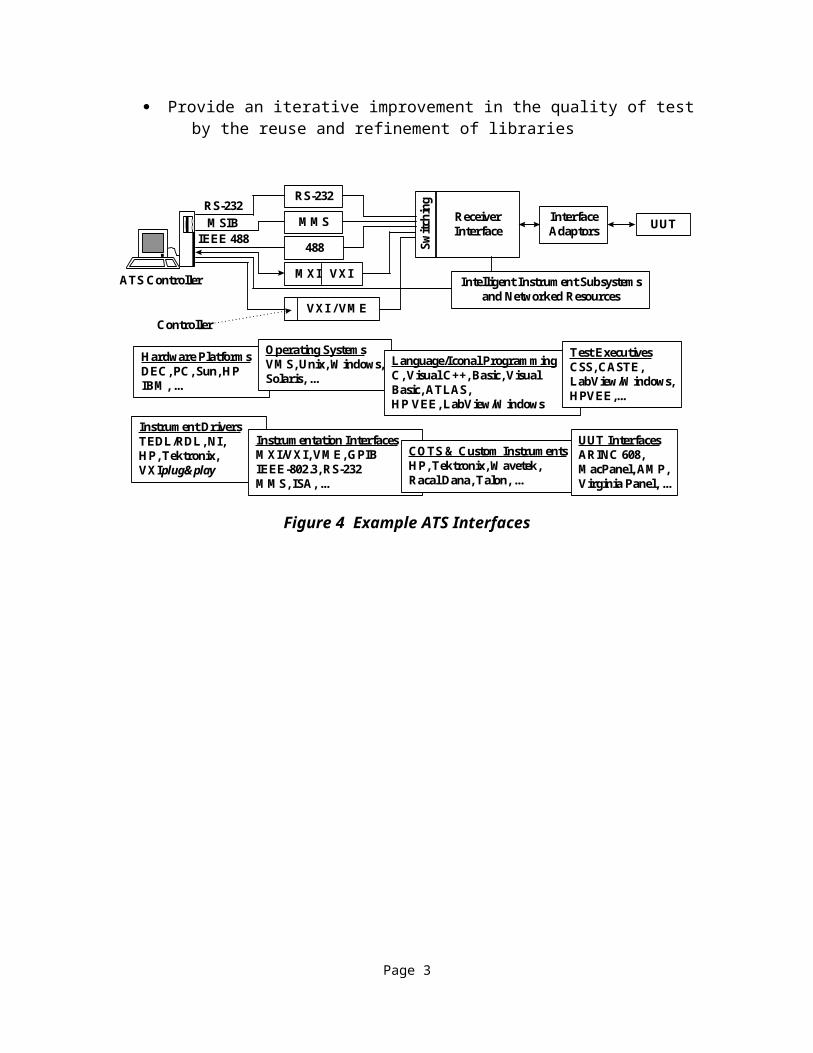
2.1PurposeRecent DoD policy changes require that “Automatic Test System capabilities be defined through critical hardware and software elements”. The purpose of this document is to define these critical hardware and software elements through Critical Interfaces (CIs). This document will aid in satisfying the requirements of DoD Regulation 5000.2-R and assist convergence in migration plans for the DoD designated tester families. Within the Joint-Service ATS Research and Development Integrated Product Team (ARI), the Critical Interfaces Working Group (CIWG) was established. The CIWG identified interfaces as critical if they offered the potential to lower the cost to re-host Test Program Sets (TPSs) and increase the interoperability among DoD test equipment. Interfaces with significant impact on Automatic Test Equipment (ATE) interoperability and TPS re-hostability, but without the ability to be implemented in the short term due to lack of commercial standards or products that support them, are recommended for further study.This document provides the requirements for each interface recommended for control along with the rationale utilized in determining its criticality. In general, criticality for each interface is based upon its ability to reduce the cost of transporting TPSs among ATE horizontally and vertically within DoD maintenance organizations and to reduce the cost of re-hosting TPSs to DoD testers and commercial testers that contain the controlled interfaces. Figure 4 illustrates some interfaces in a typical tester architecture.
2.2BackgroundFrom 1980 to 1992, the U.S. Department of Defense (DoD) investment in depot and factory Automatic Test Systems (ATSs) exceeded $35 billion with an additional $15 billion for associated support. Often, application specific test capability was procured by weapon system acquisition offices with little coordination between DoD offices. This resulted in a proliferation of different custom equipment types with unique interfaces that made the DoD appear to be a variety of separate customers. The policy changes listed below require DoD offices to take a unified corporate approach to purchases of ATE.
· DoD ATS Policy, USD (A&T) - 15 March 1996, and DoD Regulation 5000.2-R3 bring a cost effective approach to the acquisition of ATE. This policy requires hardware and software needs for depot and intermediate-level applications to be met using DoD designated families and commercial equipment with defined interfaces and requires the management of Automatic Test Systems (ATS) as a separate commodity through a DoD EAO
· Secretary of Defense Memorandum on Specifications and Standards - 29 June 1994, directs that DoD procurements will be made first by performance
3 DoD Regulation 5000.2-R, dated 15 March 1996. “DoD Automated Test System (ATS) families or COTS components that meet defined ATS capabilities shall be used to meet all acquisition needs for automatic test equipment hardware and software. ATS capabilities shall be defined through critical hardware and software elements. The introduction of unique types of ATS into the DoD field, depot, and manufacturing operations shall be minimized.”
Page 1

definition, second by commercial standards, and finally (and only with waiver) by military standards
The use of open standards in ATE has been projected to provide the following five benefits.4
· Improve the test acquisition process by creating an ATS framework that can meet functional and technological needs, promote automation in software development, re-hostability and portability of TPSs
· Decrease the use of custom hardware from approximately 70% today to 30% by the year 2000
· Reduce TPS engineering costs 70% by the year 2000· Reduce TPS integration time and cost 50-75% by the year 2000· Provide an iterative improvement in the quality of test by the reuse and refinement
of libraries
Hardware PlatformsDEC, PC, Sun, HPIBM, ...
Example ATS Interfaces
Instrument DriversTEDL/RDL, NI,HP, Tektronix,VXIplug&play
Instrumentation InterfacesMXI/VXI, VME, GPIBIEEE-802.3, RS-232MMS, ISA, ...
COTS & Custom InstrumentsHP, Tektronix, Wavetek,Racal Dana, Talon, ...
UUT InterfacesARINC 608,MacPanel, AMP,Virginia Panel, ...
RS-232
MMS
488
MXI VXI
VXI / VME
RS-232MSIB
IEEE 488 Switc
hing
ReceiverInterface
InterfaceAdaptors UUT
ATS Controller
Controller
Intelligent Instrument Subsystemsand Networked Resources
Operating SystemsVMS, Unix, Windows,Solaris, ...
Language/Iconal ProgrammingC, Visual C++, Basic, VisualBasic, ATLAS,HP VEE, LabView/Windows
Test ExecutivesCSS, CASTE,LabView/Windows,HPVEE,...
ex_ats_i Figure 4 Figure 4 Example ATS Interfaces
4Institute for Defense Analysis (IDA) Investment Strategy Study 1993
Page 2

3Programmatics
3.1OrganizationThe CIs were developed within a joint Government/Industry working group to aid in promoting commercial compatibility and vendor acceptance. The CIWG consists of representatives from the Air Force, Army, Navy, Marine Corps, engineering support contractors, vendors, and consultants with expertise in ATS. Overall guidance for CIWG activities was provided by representatives of the DoD EAO.The CIWG, funded under the title Factory-to-Field Integration of Defense Test Systems, was chartered as a working group under the ARI. Prior to the inception of the CIWG, the Air Force initiated an activity known as the Open Architectures Integrated Product Team (OA-IPT) that had similar goals to the CIWG. Given the similarity in goals and the fact that the OA-IPT had collected data needed by the CIWG, the two teams merged. Figure 5 shows the organization of the CIWG.
CIWG Organization
Critical InterfacesWorking Group
Planning
IndustryReview
DemonstrationPlanning
SoftwareInterfaces
HardwareInterfaces
NSIAATC
org4irb_a Figure 5
Figure 5 CIWG Organization
3.2ObjectivesThe CIWG was chartered to define interfaces which could be validated through demonstration and used today. In addition, the CIWG was chartered to identify interfaces worthy of further research for the long term.The primary objectives of the Critical Interfaces Project are summarized below.
· To develop critical test interface definitions from among selected and existing CIs in conjunction with commercial and defense test industries. CIs are either hardware or software, or a combination of hardware and software, which promote TPS reuse and interoperability among testers that contain those interfaces.
· To demonstrate critical test interfaces on Consolidated Automated Support System (CASS) and Integrated Family of Test Equipment (IFTE) at a minimum, and

on a commercial tester if cost and schedule can be met. The purpose of the demonstration is to evaluate the benefits of the CIs.
· To contribute to test system migration plans to evolve current DoD tester families to common test interfaces and open test environments through Preplanned Product Improvement (P3I) programs where feasible and cost effective
· To develop investment and benefit parameters needed for implementation assessments
3.3ProcessThe CIWG is utilizing a spiral process for defining and recommending CIs. Figure 6 shows the process flow and feedback loops for iteratively defining the CIs and migrating to an open systems architecture. The Open Systems Joint Task Force (OSJTF) is providing Office of the Secretary of Defense (OSD) and the EAO with the policies and procedures that are necessary to adequately define an open systems architecture. These policies and procedures are then made available to the CIWG through the ARI for further definition and refinement of the CIs. Recommendations from the OSJTF and the CIWG provide the EAO and (OSD) with data necessary for making acquisition policy and guidance decisions.This report represents the initial recommendations of the CIWG to the EAO. The interfaces recommended for Release 1 have been reviewed by industry via an Industry Review Board (IRB) process. The initial recommendations will be further refined via demonstrations, producing a Release 2 report. The report recommendations will continue to be revised as commercial and defacto standards are developed to satisfy CIs that currently have no viable candidate.
Acquisition Guidance
Release 1
Demo
Release 2
Acquisition Policy
OpenSystems
Architecture
Open SystemsJoint Task
Force
OSD
EAO
ARI
CIWG
Draft Release 1
IRB
CIWG Process
Figure 6 CIWG Process

3.4ScopeThe following factors guided the CIWG in defining CIs.
· Criticality - Only those interfaces that offered a potential to reduce TPS re-host costs and increase transportability among DoD and commercial testers were considered.
· Hardware and Software - Hardware and software associated with the supported test domains and software interfaces required to build ATSs were considered. The definition of software interfaces includes the test information and electronic information exchange of all types (e.g., digital vectors, test strategy reports, netlists).
· Open Architectures IPT - The responses to the OA-IPT Request For Information as well as interfaces identified in the responses were considered.
· Preference - Both commercial and DoD specific interfaces were considered. Preference was given to interfaces used in commercial test systems over those employed in DoD test systems.
· Signals and Testing Levels - The scope was limited to digital, analog, Radio Frequency (RF), and microwave electrical signals and to factory, depot, and intermediate (I-level) test environments.
The following factors guided the CIWG in selecting candidates for each CI.· Availability - Preference was given to candidates that are currently available or
expected to be available for the demonstration.· Commercial Acceptance - Preference was given to candidates that are available
from multiple sources and are widely accepted.· Efficacy - Preference was given to those candidates that are perceived to be more
effective in reducing TPS re-host costs and promoting TPS/ATE interoperability.
· Openness - Preference was given to candidates for which there are open, commercial standards and specifications.
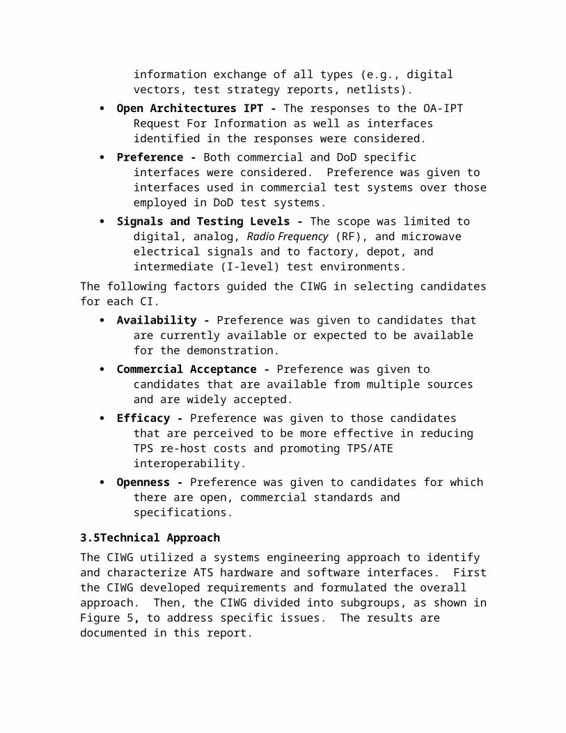
3.5Technical ApproachThe CIWG utilized a systems engineering approach to identify and characterize ATS hardware and software interfaces. First the CIWG developed requirements and formulated the overall approach. Then, the CIWG divided into subgroups, as shown in Figure 5, to address specific issues. The results are documented in this report.Each subgroup used the following process to identify and characterize interfaces and candidates.
· Develop a reference architecture diagram to allow identification and description of interfaces
· Identify interfaces· Develop criteria for evaluating the criticality of identified interfaces

· Apply criteria to interfaces and identify the CIs· Select candidates for the CIs· Provide the results for review by the full CIWG
Periodic meetings assured coordination and provided mutual review of interim results. Electronic mail was used extensively between meetings. A World Wide Web (WWW) page made working material available to CIWG members.Figure 7 presents a high-level overview of a typical ATS structure. The ATS structure shown portrays the major ATS system segments that play roles in the transportability and re-hostability of TPSs across ATE. The UUT is isolated in the box on the right. The TPS includes the fixture and the test program software. The ATE is comprised of the host computer, system software, instruments, switching, receiver and supporting communication buses. This ATS architecture is further subdivided in the generic hardware and software diagrams discussed in Sections 4 and 5.
Software / Test Program
Host Computer
Rec
eive
r
Bus
es
Switching
Instruments
UUT
Fixt
ure
General ATS Architecture
genatsar Figure 6
Figure 7 Generic ATS Architecture
A variety of diagrams in the hardware and software sections of the report relate to the architecture shown in Figure 7. The critical hardware and software interfaces are analyzed by expanding the boxes shown.The group reviewed architectural diagrams of the current DoD designated families of testers. Figure 8 shows the CASS hardware architecture while Figure 9 shows the CASS software architecture. Figure 10 shows the IFTE hardware architecture while Figure 11 outlines the IFTE software architecture. These architectural diagrams were used as a baseline to develop a generic view of hardware and software elements that are common to most tester architectures.
ATS Critical Interfaces Report
Switching-Receiver SignalCable Interface
488.2
VME488488.2
VME
488.2
VME
VAX or ALPHA Computer
68000 BasedAsset Controllers
VirginiaPanel
Receiver
InterfaceDevice
(ID)
UUT
Instrument-Receiver SignalCable InterfaceSwitching
(Internal and UUT)
Fixture-UUT SignalI/O (Cable)Interface
Receiver-Fixture SignalI/O Interface
InstrumentTriggers/ UUT
Synchronization
Instrument/SwitchingCable Interface
Instrument- UUTSignal Cable
Interface
VAX 488InstrumentInterface
QBUS orPCI/MXI 2
Digital Test Unit (DTU)
MSIB Gateway
488
488MMS
VME basedInstruments
RF
Station I/F
Station I/F
CASS Hardware Interfaces
ExternalEnvironments
InternalEthernet
ExternalEthernet
cass_hw_i Figure 7 Figure 8 CASS Hardware Architecture
Page 5

ATS Critical Interfaces ReportCass Software Interfaces
VAX or ALPHA Computer
Software /Test Program
Ass
etC
ontr
olle
rs
Stat
ion
Inte
rfac
es
Switching
InstrumentsUUT
Fixt
ure
CASS Runtime Services (IMOM, AA, ATI)
TestProgram
ATLASTest
Executive
Virtual
InstrumentHandlers
CommunicationsHandler
488
Commands
VAX Framework
488
DTU
Motorola 68000 Framework
Instrument PersonalityInterfaces (IPI)
(Instrument Drivers)
RegisterBased
Commands VME
Motorola 68000 Framework
Motorola 68000 Framework
GAM/KAM
GAM/KAM
GAM/KAM
E/OInstrument Personality
Interfaces (IPI)(Instrument Drivers)
488Commands
MMSInstrument Personality
Interfaces (IPI)(Instrument Drivers)
SCPICommands
SICLDrivers
VMS OS
488Translator
488Commands
VAX Framework
VMS OS
DigitalFEPS
[VXI/MXI2]Driver
Teradyne Test Executive
cass software Figure 8Figure 9 CASS Software Architecture
Page 6

ATS Critical Interfaces Report
IFTE Hardware Interfaces
Gold DotReceiver
Fixture
VME Instruments
Switching MatrixReceiver SignalCable Interface
Receiver-Fixture SignalI/O Interface
Instrument Triggers /Synchronization
Fixture - UUTSignal I/O
(cable) Interface
UUT
ExternalEnvironments
Instrument - ReceiverSignal Cable Interface
SignalDistribution
Center
VIC ResourceController (Sparc 5 )
Peripheral InterfaceController (Sparc 20)
InstrumentSwitching Cable
Interface
ExternalEthernet
EthernetGPIB Instruments
GPIB Instruments
VME
IEEE-488
IEEE-488
ifte_hw_i Figure 9 Figure 10 IFTE Hardware Interfaces
Page 7

ATS Critical Interfaces Report
IFTE Software Interfaces
ATLAS Run Time System
Sun Framework
Unix OS
Software ConfigurationManager
Parameter Bufferand I/O Buffer (Driver I/F)
Remote Process Calls(Instrument Drivers)
Note: RPC’s combine functionof Driver I/F, Driver,
Instrument Communication
Host Computer
Software /Test Program
Bus
es
Rec
eive
r
Switching
InstrumentsUUT
Fixt
ure
ifte_sw Figure 10
Figure 11 IFTE Software Interfaces
Page 8
ATS Critical Interfaces Report
4Hardware
4.1Hardware InterfacesIn this section the generic ATS architecture is decomposed into hardware elements and the interconnects between them. Each interface is evaluated against its ability to reduce the cost of transporting and re-hosting a TPS to determine its relative criticality.
4.2Hardware DecompositionFigure 12 provides a view of the top-level hardware elements and interconnects in a generic ATS architecture. This diagram was developed for the purpose of representing all generic hardware interface categories which might be considered CIs. The diagram is meant as a starting point for discussions on particular interfaces and their pertinence to TPS transportability and re-hostability. The diagram is not a representation of a test system architecture, but does have resemblance of such since there is a close relationship. The following is a discussion of the diagram and some of the implications and outcomes concerning the diagram which have resulted from the CIWG hardware group.The diagram is composed of hardware elements and the interconnects existing between them. A named data flow arrow connecting two elements represents an interconnect. The elements represent general ATS system hardware components. Elements and interconnects were considered as interface candidates during the hardware group deliberations.The hardware subgroup used the ATS Generic Hardware Interfaces to visualize each interface category and how information might flow between elements. This is important since there are many test architectures and the diagram must incorporate the important interfaces for transportability and re-hostability for all of them. For instance, a test system may incorporate a distributed computing architecture like that found in the CASS. Although the diagram does not explicitly exhibit a distributed computing architecture, the interfaces that would be critical are represented. In the CASS, the host computer Central Processing Unit (CPU) communicates with asset controllers through Ethernet connections. The host CPU is represented in the diagram by the Host Computer element. The Ethernet connection is represented as a Computer to Asset Controller (CAC) interconnect. Each asset controller is represented by the Instrument/Asset Controller element.Table 6 summarizes the six primary interfaces delineated in Figure 12. It also lists the corresponding elements for the CASS, IFTE, and Teradyne architectures correlated to a listing of candidate standards and products considered for satisfying the interface.
Page 1

ATS Critical Interfaces ReportATS Generic Hardware Interfaces
Receiver Fixture
Instruments
Switching MatrixReceiver SignalCable Interface
Instrument - UUTSignal Cable
Interface
Instrument Triggers /Synchronization
Instrument ControlBus Interface
Fixture - UUTSignal I/O
(cable) Interface
UUT
ExternalEnvironments
Instrument -Receiver SignalCable Interface
RFX
SWM
SwitchingMatrix
Instrument / AssetController(s)
HostComputer CXE
InstrumentSwitching Cable
Interface
CAC
HST
atsgenhw Figure 12
RFXThree letter mnemonics indicatePotential Critical Interfaces
ICB
Figure 12 ATS Generic Hardware Interfaces
Table 6 Hardware Interfaces Summary Matrix
Interface CASS IFTE Teradyne Candidate Standards/Products
Host Computer Asset Controller interface (CAC)
QBUS, PCI, MXI, Ethernet, IEEE-488
S-BUS, Ethernet
PCI, MXI, Ethernet, IEEE-488
EISA, ISA, PCI, Ethernet, QBUS, Unibus, SCSI, S-BUS, IEEE-488, MXI
Computer to External Environments Interface (CXE)
RS-232, Ethernet
RS-432, Ethernet
RS-232, Ethernet
Ethernet, RS-232/432, IEEE-488
Host Computer (HST)
VAX / ALPHA
Sparc 20 Sparc 20 Sparc, VAX, DEC ALPHA, Intel: 80x86, Motorola: 68xxx
Instrument Control Bus interface (ICB)
IEEE-488, VME, MSIB
IEEE-488, VME
IEEE-488, VME
IEEE-488, VXI / MXI, VME, RS-232/432
Receiver / Fixture interface (RFX)
Virginia Panel Gold Dot ZIF Virginia Panel, MAC Panel, Gold Dot, AMP
Switching Matrix interface (SWM)
Internal with loopback wiring from ITA to access
Internal and software controlled. No wiring necessary on ITA
Internal and software controlled. No wiring necessary on ITA
IFTE Signal Distribution System
Page 2

ATS Critical Interfaces Report
4.3Definitions of Potentially Critical Hardware Interfaces
4.3.1Computer Asset Controller InterfaceThis interface describes the communication paths between the HST and instrument controllers or other slave processors in a distributed system. These interfaces may be internal or external to the HST. Examples of internal interfaces are Industry Standard Architecture (ISA) and Peripheral Component Interface (PCI). Examples of external interfaces are IEEE-488, RS-232, Ethernet, MXI, and MSIB.
4.3.2Computer to External Environments InterfaceThis interface describes the communication methods between a host ATS and remote systems. This includes paths between the target ATE host computer and other ATE systems as well as development stations. This interface supports transporting TPS software and supporting documentation between organizations and re-host of legacy TPSs. Examples include Ethernet for Local Area Networks (LAN) and Wide Area Networks (WAN), RS-232, IEEE-488, and Ethernet for point-to-point connections, as well as modem links.
4.3.3Host Computer InterfaceThis interface describes the processing architecture of the primary control computer where the TPS is executed and through which the operator interfaces.
4.3.4Instrument Control Bus InterfaceThese are interfaces from the instrument controller to test instrumentation such as Programmable Power Supplies, Arbitrary Waveform Generators, Spectrum Analyzers, Digital Test Units (DTUs), and Power Meters. Examples of these interfaces are IEEE-488, VME, and VME Extensions for Instrumentation (VXI).
4.3.5Receiver/Fixture InterfaceThis interface describes the hardware necessary to accomplish the mechanical and functional connections between the UUT stimulus/response signals passing through the UUT’s unique ITA and the signals to and from the test instrumentation. These signals are passed either directly to or through the test instrument or through a hardware switch.
4.3.6Switching Matrix InterfaceThese interfaces describe the hardware switching requirements necessary to switch stimulus, response, and power signals between the UUT and the test instrumentation. The switching may be implemented in various ways such as internal to the tester or external in the fixture.
4.3.7Hardware Interface Criticality EvaluationA large number of tradeoffs between hardware and software exist. Whenever such tradeoffs were encountered, the general decision was made to implement the software interface instead of the hardware interface. Software interfaces allow a wide variety of hardware and provide a more “open” system. Thus, the specification of the VPP-2
Page 3

ATS Critical Interfaces Report
frameworks in the software section (Section 5) provides a reason that the Host Computer is not a CI. The VPP-2 specification places minimum requirements on the Host Computer, peripherals, operating systems, and ADEs, without specifying particular products. Under these ground rules, the majority of hardware elements were not considered critical because the software elements that isolate or limit them were considered critical.The group concluded that interfaces touched by the TPS through its life cycle are prime candidates for CIs (refer to Figure 13). That is, if an interface directly supports the design, development, production, use, or re-host of a TPS then it has the potential to be a CI.
.1
CPUOS
TPS
Any Point in TPS Life Cycle
TPS Life Cycle
tps_life Figure 12
Figure 13 Test Program Isolation From Host Computer
Figure 13 demonstrates that the TPS is isolated from the CPU by the Operating System (OS). Since the TPS does not directly touch the CPU, the host computer is not a CI. Following this logic, the CAC and ICB interfaces were eliminated.An example of a situation where an interface is deemed critical follows. Figure 14 shows a TPS contacting the CXE interface during a re-host. In this example the Ethernet is an implementation of the CXE interface. Since the two OS communicate via the same network protocol, the TPS can be transferred regardless of the OS type.
TPS Re-Host
Ethernet
CXE
rehost Figure 13
Source ATE System Target ATE System
OS TPS OSTPS
Figure 14 Re-host of a TPS
Several hardware elements not recommended as CIs, for the reasons discussed in the preceding paragraphs, became required as a result of software interfaces. These hardware elements are necessary to support certain software interfaces described in Section 5. The elements include, but are not limited to, the CPU, memory requirements, peripheral support and others.
Page 4

ATS Critical Interfaces Report
4.4Recommended Hardware Critical InterfacesUsing the concepts in the previous section, the following hardware interfaces are critical.
· Computer to External Environments· Receiver/Fixture Interface· Switching Matrix
Each of these CIs is discussed in the subsequent sections.
4.4.1Computer to External Environments Interface
4.4.1.1Computer to External Environments CandidatesThe CXE interface defines hardware that allows communication between an ATS and remote systems. This interface supports transporting test program software and supporting documentation between organizations. The candidates considered include Ethernet, RS-232, and IEEE-488.
4.4.1.2Computer to External Environments Recommendations and RationaleThe CXE interface was selected as a CI because standardizing it is expected to reduce the cost of transferring information during re-host of a TPS. Analysis of software issues concluded that data networking using TCP/IP should be required. It was not necessary to specify a particular hardware interface candidate such as Ethernet, RS-232, or IEEE-488, because TCP/IP implementations can be used in conjunction with a number of hardware solutions. The CIWG recommends that any hardware used in this interface be required to support the TCP/IP software protocol.
4.4.2Switching Matrix Interface
4.4.2.1DecompositionThe SWM interface and ATS receiver/fixture pin map represents a central element of the ATS for connecting ATE instrumentation to the UUT through a switch matrix. The SWM allows a variety of instruments to be connected to multifunction terminals identified by a standard receiver/fixture pin map. The pin map is described in the section for the RFX interface. The combination of standardizing the SWM interface and a common receiver/fixture pin map gives the ATE the capability to accommodate any fixture that conforms to the pin map. The SWM and receiver/fixture pin map interface have the greatest impact by permitting the ATS developer to select various signal paths between the instrument and UUT. A description of the SWM interface, selection criteria, and recommendations follow.A variety of switch matrix designs can be interfaced to and from instruments and the related UUT. Examples of switch matrices are shown in Figure 15 as:
· Benchtop units· Integrated switch cards to fixturing or directly coupled to receiver interfaces· Rack mounted units· VXI Switch Modules
Page 5

ATS Critical Interfaces Report
.2
orPC/AT/XTInterfaceModule
COAXIAL
MULTIPLEXER
MATRIX
or Bench Top Units
VME/VXI Mainframeor PC Bus Modules
Computer
VME/VXI Switch Module
Controller /Command
Module
COMPUTER CONTROL VIA
IEEE 488 BUS
RS 232 Serial
RACK & STACK Matrices,Multiplexers and Coaxial
Switches
Switching Matrix Product Designs
swm_dsgn Figure 14Figure 15 Switching Matrix Product Designs
4.4.2.2Requirements and Issues ConsideredGeneral requirements for the SWM CI were derived from many sources representing general industry needs, Government and commercial interests, Government Open-System directives, industry technology trends, NSIA recommendations, Government/Aerospace test requirements previously described (functional test requirements), and Test Industry SWM defacto standards. The CIWG reviewed the widest spectrum of requirements and interests to assure worst case needs were addressed. These requirements were extracted from the envelope of the cases reviewed. This is expected to provide capability for almost every requirement the solution will encounter. During the review process standards or products that could meet these requirements were sought. The switching philosophies considered in the analysis are as follows.
· Switching in the Test Fixture - This approach incorporates switching into the test fixture based on the UUT requirements. This places financial burden on the end user since switching needs to be incorporated in many test fixtures. This is a significant recurring cost.
· Switching in the ATE - This approach integrates the switching capability into the ATE and treats it as additional instrumentation. This simplifies test fixture
Page 6

ATS Critical Interfaces Report
design, reduces TPS cost, and places the switching under control of the ATE system software. This can be accomplished in one of two ways.
1. “Internal hardwiring” of instrumentation to ATE switching. The internal approach simplifies test fixture design and implementation; however, a performance tradeoff may be incurred.
2. “External hardwiring” of instrumentation to ATE switching in the test fixture. The external approach will greatly increase test fixture complexity, however; the TPS developer has greater flexibility, should higher performance instrumentation require uncompromised access at the tester interface.
4.4.2.3General RequirementsThe SWM CI includes all of the needs that address hardware/software requirements. These lead to a system that can support commercial architectures and preserve the needs of the Government and commercial industry. The following goals directed the review of switching matrix candidates.
· Select an open commercial switch matrix standard that:3. Is widely accepted by industry with multi-vendor sources.4. Has established design definitions.5. Offers a full range of options to meet signal, power, and coax
requirements.6. Supports high life cycle performance and maintainability.7. Is available today in volume production, and is in its early product life-
cycle phase.· Provide a scaleable switch matrix with a modular framework design that permits
ATS integrators to incrementally augment their systems through add-on/duplicative features. This will enable them to meet worst case requirements while maintaining downward compatibility with any smaller Input/Output (I/O) increment.
· Establish a common switch matrix specification that offers multi-vendor sources, is flexible enough to support a wide variety of signal performance/reconfigurability, and can evolve with changing test needs.
· Minimize pin out configuration to the extent that transportability is effective and reconfigurability is not impaired.
· Reduce the proliferation of switch matrix designs.· Define a minimum set of performance requirements that will meet the
Government I/O basic switch matrix envelope.The integrator determines switch requirements based on the number of instruments and the flexibility with which they must be applied. Switch matrix designs require a compromise between direct wire performance and switch flexibility.
Page 7

ATS Critical Interfaces Report
The CIWG concluded that switching in the ATE with internal hard wiring should be required to achieve greater cost-effectiveness and minimize fixture complexity. Extended performance paths should be included to address high performance requirements.The CIWG also concluded that the SWM must meet the following requirements.
· IEEE-488.2 protocol· VPP-3 instrument drivers and VPP-4 I/O libraries
Packaging of the switches should be in one of two forms.· 19Ó rack mounted unit· VXI bus standard B or C module form factor
4.4.2.4Current Government ATE RequirementsBased upon the general requirements of the Government and existing ATS requirements of the Teradyne L300-Series system, CASS, IFTE, and Marine Corps Automatic Test Equipment System (MCATES); a composite I/O interface matrix capability envelope was developed to define current/worst case requirements. This was divided into several I/O categories to permit signal mapping to pin type of the RFX.
· Digital (DTU/DWG)· General Purpose Analog Instrumentation· Programmable DC Load (High Power)· Programmable Power Supplies (AC/DC)· Serial Communication for UUTs (e.g., 1553, RS-232, RS-423)· Utility Switching I/O
Applying the modular and scaleable concepts offered by commercial switch matrices, a minimum set of switch assets should be defined that can be duplicated to support worst case requirements.It was determined that the following capabilities would not form part of the core capability, and that they should not be addressed by this report: Electro-Optics (E/O), Pneumatics, RF, Spread Spectrum, Video and unique ATE configurations including instrumentation of this type.
4.4.2.4.1Programmable DC Power SuppliesTable 7 compares the programmable DC power supply capabilities of selected ATE including pin count per instrument, voltage and current ratings. The pin count was based upon three pin types covering overlapping voltage bandwidths of the CASS low power5 10A contact and the CASS high power6 20A contact. Use of these pins is driven by TPS requirements and can only be estimated.
5The CASS low power (10A) connector is an open specification designed around Virginia Panel P/N 610 115 112 and P/N 610 116 112.6 The CASS high power (20A) connector is an open specification designed around Virginia Panel P/N 610 110 129 and P/N 610 110 128.
Page 8

ATS Critical Interfaces Report
Table 7 DoD ATS Programmable DC Power Supply Configurations
ATS Power Supply Description Voltage / Current Rating # High Contacts
# Low Contacts
L300-Series DCPS 1DCPS 2DCPS 3DCPS 4DCPS 5DCPS 6DCPS 7DCPS 8
0-20V, 30A0-60V, 10A0-200V, 17A0-10V, 6A0-20V, 50A0-60V, 12A0-360V, 17A0-32V, 32A
Total:
2222222216
2222222216
CASS DCPS 1 - DCPS 5DCPS 6 - DCPS 8DCPS 9DCPS 10, DCPS 11(all) 1
0-32V, 25A0-32V, 25A0-100V, 8A50-450V, 2A
Total:
2012
32
1064828
IFTE DCPS 1, DCPS 2DCPS 3, DCPS 4DCPS 5DCPS 6, DCPS 7DCPS 8Fixed Power Supply4
(all) 2
0-7V, 20.5A0-15V, 9.1A0-36V, 4.1A0-55V, 2.5A0-100V, 1.5A+28V, 22.5A
Total:
84242626
16168168-
64 3
MCATES DCPS 1, DCPS 2, DCPS 8DCPS 3DCPS 4, DCPS 5DCPS 6, DCPS 7(all) 1
0-16V, 2A0-150V, 0.7A0-55V, 8A0-36V, 8A
Total:
624416
624416
Note 1. Each supply requires two high power pins (Hi, Lo) and two low power pins (Sense Hi, Sense Lo).
Note 2. Each supply requires two high power pins (Hi, Lo) and eight low power pins (SW1+, SW1-, SW2+, SW2-, SW3+, SW3-, SW4+, SW4-).
Note 3. Spare medium power or signal pins could be used to support Sense contact requirements.
Note 4. IFTE contains an additional fixed DC power supply as follows: + 28V, 22.5A accessible at the Auxiliary Interface Panel, enabled by shorting two pins on the Gold Dot Interface panel together.
4.4.2.4.2Programmable DC LoadsTable 8 compares the programmable DC load capabilities of selected ATE including pin count per instrument, voltage and current ratings. The pin count was based upon three pin types covering overlapping voltage bandwidths of the CASS low power 10A contact and the CASS high power 20A contact. Use of these pins is driven by TPS requirements and can only be estimated. Further research in Phase II should provide greater definition on
Page 9

ATS Critical Interfaces Report
the number of pins by pin type. Where requirements exceed the amperage rating of the CASS high power contact, parallel path wiring (doubling) is recommended.
Table 8 DoD ATS Programmable DC Load Configurations
ATS Programmable Load Description # High Contacts
# Low Contacts
L300-Series 3 Loads, 150W, 250W, and 600W (available at external panel only, they do not go through the switch matrix)
Total:
14
14
6
6CASS High Power Load (500W, 20A) = 2 High Power and 3
Sense Low Power pins.Low Power(0.5A) = 2 low power pins, 8 more low power in future needs 16 additional low power.
Total:
2
-
2
3
26
29IFTE 8 Channels, 2x300W, 6x750W (avail. at AUX panel only)
Total: 1616
3535
.3MCATES .4none .5 .6
4.4.2.4.3AC Power Supply RequirementsData in Table 9 compares the AC power supply capabilities of selected ATE after an analysis of:
· Current· Pin Count· Voltage
Page 10

ATS Critical Interfaces Report
Table 9 DoD ATS AC Power Supply Configurations
ATS Phase Voltage(VRMS)
Frequency(Hz)
Current(Amps)
Power Config. Access
L300-Series Single or Three
0 - 200 60 - 1600 0 - 10 3.5 KVA Delta,Wye
ExternalPanel
CASS Single or Three
0 - 135 55 - 1200 0 - 13.5 675 Watts/Phase
Delta AC PowerPanel
IFTE Single or Three
0 - 270 45 - 5000 0 - 135 V @ 10 A0 - 270 V @ 5 A
750 Watts/Phase
Delta,Wye
AuxiliaryInterfacePanel
MCATES none none none none none none none
The AC power capabilities of these systems are not accessible at the receiver interface; therefore, they do not affect pin mapping at this interface. For personnel safety and Electromagnetic Interference (EMI) noise restrictions, the AC power lines connect through an auxiliary AC power panel to the UUT or fixture assembly.
4.4.2.4.4Summary Power Supply RequirementsTo support the power I/O requirements of the RFX CI for the selected ATE families, it is desirable to map the I/O contact requirements against the CASS power contacts having varying levels of performance that is primarily segmented by its amperage rating. The recommended contacts are:
· High Power - 20 Amp CASS power contact· Low Power - 10 Amp CASS power contact
Based upon current CASS contact densities, a mixed power connector module is required to support the same footprint as the 200 pin DIN signal module. Assuming the present pin cavity and spacing used by CASS and a DIN footprint, it is possible to pack sixteen high power contacts; and twenty-nine low power/sense pins in one mixed power connector module.The analysis concluded that current ATS requirements can be met with four mixed power connector modules. Two of the power modules would be dedicated for direct interface to the programmable DC power supplies and two would be devoted to the power switch matrix.
Page 11

ATS Critical Interfaces Report
4.4.2.4.5Digital I/O CapabilitiesTable 10 compares the digital I/O capabilities after the analysis of:
· Bandwidth· Crosstalk· Pin Count
A commercial DIN format 200 position signal connector module connected to precision point-to-point 50 ohm impedance matched wiring having a bandwidth up to 250 MHz was evaluated and found acceptable for use with the selected ATE digital requirements.
Table 10 DoD ATS Digital I/O Capabilities
ATS # of I/O Pins Pin Description (Voltage)L300-Series 532 -2.56 to +10.23 VCASS 336 -5.0 to +15.0 VIFTE 160
32-10.0 to +10.0 V-10.0 TO +30.0V
MCATES 25664
-2.0 to +5.0 V-28.0 to +28.0 V
Each 200 pin DIN signal connector module could support 64 digital I/O pins and their associated control lines. Nine DIN signal connector modules would be required to support the 532 pin L300-Series requirement.
4.4.2.4.6Analog Instrumentation RequirementsData in Table 11 compares analog instrumentation capabilities of selected ATE including:
· Bandwidth· Maximum Voltage· Pin count
The pin count was based upon three pin types covering overlapping frequency bandwidths:· Low - commercial DIN signal DC to 250 MHz contact· Low RF - CASS Low RF < 1.2 GHz coax contact· High RF - commercial High RF < 26.5 GHz coax contact
Use of these pins is driven by TPS requirements and could only be estimated. Further research will provide greater definition on the number of pins by pin type.
Page 12

ATS Critical Interfaces Report
Table 11 DoD ATS Analog Instrumentation Descriptions
Instrument L300-Series IFTE CASS MCATES
Mil-Std -1553/BUS TEST UNIT
1553 Bus Emulator Bus Test Unit, 2 channels requires 26 pins. Future is 1553 Bus Emulator.
1553 Bus Emulator also requires 2 Coax ports. Future is more General Purpose Serial Interface
None
DMM High, Low, Sense High, Sense Low, GND
High, Low, Ohms Sense Hi, Ohms Sense Lo
High, Low, Ohms Sense Hi, Ohms Sense Lo, Current Measurement pin
2 Channels of High, Low, Ohms Sense Hi, Ohms Sense Lo, also Trig and Current measurement pin.
COUNTER / TIMER
CH1, CH2 CHA, CHB, EXT TRIG
CHA, CHB, EXT TRIG
CHA, CHB, CHC, CHD, REF OUT
DIGITIZER / WAVEFORM ANALYSIS
CH1, CH2, EXT TRIG
CHA, CHB, EXT TRIG
CHA, CHB, CHC, CHD
CHA, CHB, EXT TRIG, CHB OUT, Audio Analyzer
ARBITRARY FREQUENCY WAVEFORM GENERATOR (AFG/AWG)
CH1, CH2, EXT TRIG,
AC Signal: CH1, CH2 Video Signal: VIDEO
CHA, CHB, CHC, CHD, All Channels have EXT TRIG; CHA, CHB, CHC have EXT SYNC
CHA, CHB, EXT TRIG, EXT SYNC, 12 Channel ECL Pulsed Out (not used with AFG)
Two (2) Pulse-Function Generators, each with EXT TRIG IN, OUT, Control MOD IN
PRECISION DC REFERENCE DIGITAL TO ANALOG CONVERTER (DAC)
None 8 Channels presently, 12 in the future with EXT SENSE for each channel
None. Study in progress for future enhancements.
None
PULSE GENERATOR
CH1A, CH1B, CH2A, CH2B, EXT TRIG 1, EXT TRIG 2
AFG CHA, CHB, CHC, CHD (25 MHz), Each with EXT TRIG; CHA, CHB, CHC, have EXT SYNC
CHA, CHB (250 MHz), Plus one Trigger
CHA, CHB, EXT GATE IN, TRIG OUT
SYNCHRO RESOLVER SIMULATOR / INDICATOR
None 1 Channel SRSI, 3 Channels SRSI in Future
3 Channel SRSI None
10 MHz REFERENCE
None 10 MHz Reference available at receiver
10 MHz Reference available at receiver
10 MHz Reference available at receiver
SYNCHRONIZATION AND TIMING
Various signals available at UUT Interface, Optional
None None. Coax IN, two twisted pair OUT
Coax IN, Coax OUT
Page 13

ATS Critical Interfaces Report
Instrument L300-Series IFTE CASS MCATES
external clock input
CALIBRATOR None None None. Low Frequency Calibrator accessible at receiver
None
SERIAL COMMUNICATIONS FOR UUT
ARINC 429, RS-232 (at external interface only, not available through switch matrix)
RS-423, RS-232 (AT MASS INTERFACE), IEEE-488, Ethernet VIA AUX PANEL
RS-232, RS-422, IEEE-488, IEEE 802.3, ARINC 429
RS-232 AND IEEE-488 AT AUX PANEL, MXI via TESTHEAD
GROUND Chassis, single-point ground
Chassis, single-point ground
Chassis, single-point ground
Chassis, single-point ground
INTERLOCKS DC Power Supply interlocks at external interface, fixture disconnect interlock
None One deals with ID being open (2 pins), the other with UUT cabling (3 pins). If there is a fault, the station will not run the TPS. In 1995 P3I added 11 additional lines to allow the TPS developer to monitor conditions at the UUT, (i.e. overtemp would shut down the station).
Receiver provides interlock which, when opened prohibits closing of any switch or application of any stimulus. The TESTHEAD also provides a sense capability for an ID safety cover.
PROBE CAPABILITY
DTU Guided Probe (probe in 18 different detect states), PROBE CAL, ANALOG PROBE PORT (provides access to all switch MATRIX assets)
DWG Guided Probes (stimulus, response (level, pulse, etc.), and current detect), 2 ANALOG PROBE PORTS (provide access to all MATRIX switch assets), HIGH FREQ PROBE (100 KHz-5OO MHz) and HIGH VOLTAGE PROBE (40 KV DC Max) used with the DMM
DTU Guided Probe (probe in 18 different detect states), PROBE CAL, DMM HV PROBE, AND DIGITIZER CAL PROBE
Digital Guided Probe, Level, Pulse, Glitch Detect
Page 14

ATS Critical Interfaces Report
4.4.2.4.7Analog Instrumentation Requirements SummaryUsing a worst case analysis, the number of pins required for analog instrumentation on selected ATE are shown in Table 12. It is assumed that no switch matrix is present in deriving these numbers.
Table 12 DoD ATS Analog Instrumentation Requirements
Instrument Contact Requirements Signal Low RF High RF1553/BTU 30 signal pins 30DMM 10 signal pins 10Counter/Timer 4 coax pins 2 2Digitizer 12 coax pins 10 2AFG/AWG 13 coax + 25 signal pins 24 12 2DAC 60 signal pins (includes expansion) 60Pulse Generator 7 coax pins 5 2Synchro/Resolver 50 signal pins 50Sync/Timing 1 coax + 6 signal pins 6 2Calibrator 5 signal pins 510 MHz Ref. 1 coax pin 1Audio Analyzer 4 signal pins 4
Totals: 189 30 10
To support the analog I/O requirements of selected ATE, three types of contacts were recommended:
· Low frequency analog, DC to 250 MHz· Low RF analog, 100 MHz to 1.2 GHz· High RF analog, 500 MHz to 26.5 GHz
It is desired to have as a minimum, the following:· One 200 position low frequency signal module· Two 24 position low analog/RF coax modules· One 12 position high analog/RF coax module
Page 15
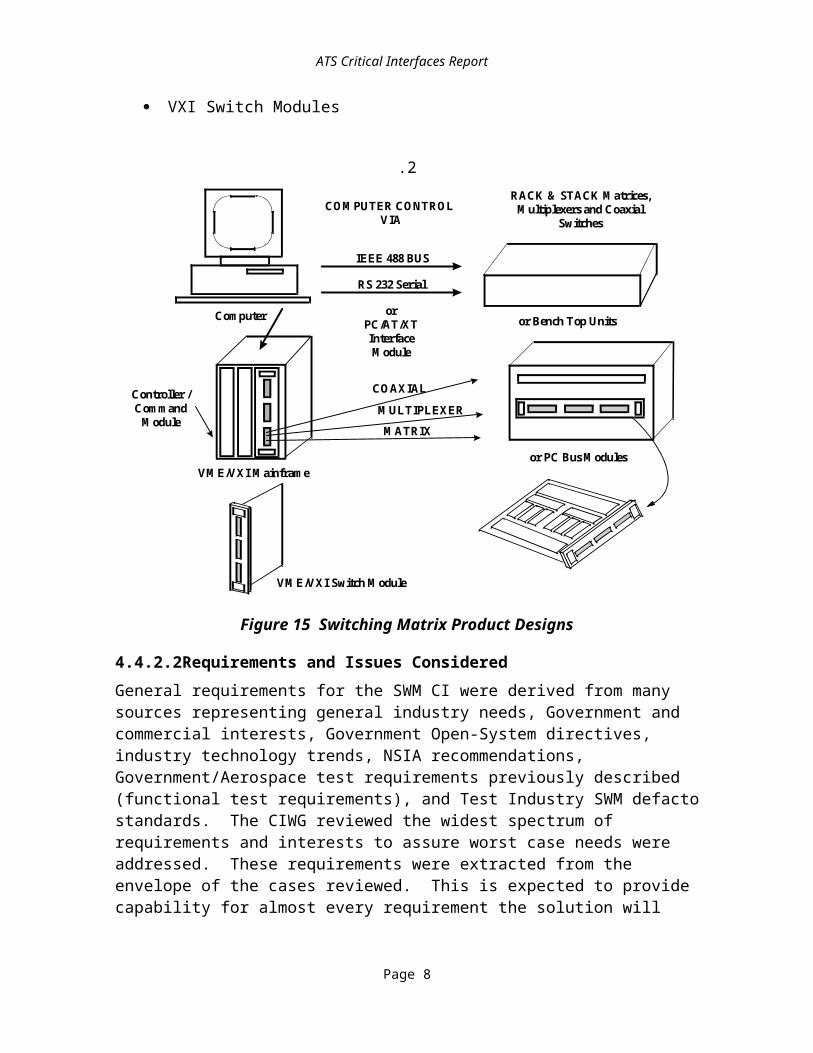
ATS Critical Interfaces Report
4.4.2.4.8Power Switch Matrix RequirementsThe present power switching capabilities of selected ATE are summarized in Table 13.
Table 13 DoD ATS Power Switch Matrix Requirements
ATS Power Requirements # High PWR Pins # Low PWR PinsL300-Series NoneCASS 5 x (1x4) @ 18.75 Amp
3 x (1x2) @ 18.75 Amp6 x (1x2) @ 9 Amp
Totals:
259
341818
IFTE1
MCATES None
Note 5. Switching is built-in to DC Supplies, pins were accounted for in programmable DCPS section.
Assuming a 16/29 position High/Low mixed power connector module, two power modules are required to support worst case needs of the CASS power switch. It is unclear whether use of the current discrete DC power supplies connector modules could be used for the power supply switch outputs.
4.4.2.4.9Low Frequency Switch Matrix RequirementsThe current low frequency utility switch matrix requirements of the selected ATE are summarized in Table 14.
Table 14 DoD ATS Low Frequency Switch Matrix Requirements
ATS Switch Requirements # Signal Pins
L300-Series 16 x (1x2) @ 20 MHz16 x (1x2) @ 100 KHz16 x (1x2) @ 1600 Hz
Total:
484848144
CASS 70 x (1x2) @ 1 MHz42 x (1x4) @ 1 MHz
Total:
210210420
IFTE 32 x (1x2) @ 10 MHzTotal:
9696
MCATES 12 x (2x8) @ 10 MHz14 x (1x2) @ 10 MHz6 x (1x4) @ 10 MHz
Total:
1204230192
Page 16
ATS Critical Interfaces Report
The requirement for a utility switch matrix is needed for any general purpose ATE system. One 200 pin DIN connector module would support the current configurations of L300-Series, IFTE and MCATES, as well as a scaled down CASS requirement. Access to utility switching by the TPS developer can simplify test fixture design, increase transportability, and reduce TPS cost. Utility switching is being defined as low bandwidth (1-10 MHz) switching with accessibility by the TPS at the system interface. Form C relays (1x2) constitute the basic and most versatile building block of all switching architectures.
4.4.2.4.10Performance Switch Matrix RequirementsThe present performance switch matrix requirements of selected ATE are summarized in Table 15.
Table 15 Performance Switch Matrix Requirements
ATS Power Requirements Power Pin TypeL300-Series 64 Ports @ 208 MHz 64 Signal, 64 Returns
400 Hybrid Signals @ 10 MHz 400 Signal, 400 Returns16 x (1x2) @ 500 MHz 48 Coax
CASS 33 x (1x4) @ 1 GHz 165 Coax9 x (1x2) @ 1 GHz 27 Coax
IFTE 48 x 3 @ 100 MHz 144 Signal, 144 Returns144 Ports @ 40 MHz 144 Signal, 144 Returns
MCATES 6 x (1x4) @ 500 MHz 30 Coax4 x (1x8) @ 500 MHz 36 Coax10 x (1x4) @ 18 GHz 50 HF Coax12 x (1x2) @ 18 GHz 36 HF Coax2 x (1x20) dedicated to DMM 42 Signal2 x (5x25) dedicated to Audio Analyzer 60 Signal
The requirement for a high performance analog switch matrix is needed for any general purpose ATE system. Four 200 pin signal connector modules would be required to support the signal pin current configurations of IFTE and L300-Series. Three low RF/analog coax 24 position modules would be required to support worst case CASS switch requirements. Eight high RF coax 12 position modules would be required to meet the MCATES worst case 18 GHz switch requirements. This would require a second tier system and a dedicated set of unassigned modules would be identified. One 12 position high RF coax module is provisioned in the first tier of the receiver to support high RF requirements.
Page 17

ATS Critical Interfaces Report
4.4.2.4.11ATS Summary Core CapabilityThe following functional capabilities are common to the L300-Series, CASS, IFTE, and MCATES testers.
· Counter/Timer: Two Channel, External Gate/Trigger· Digital I/O Pins: 192· Digital Multimeter: AC/DC Volts, Ohms· Digitizer: Two Channels, External Trigger· Function Generator: Two Channels· Probing: Digital Guided Probe· Programmable DC Power Supplies: 8 · Pulse Generator: One Channel· Utility Switching: 32x (1x2) @ 1 MHz
4.4.2.4.12Connector Module Requirements SummaryThe number of connector modules required for the selected ATE are shown in Table 16.
· Worst Case: Total number of modules required 324
· (48 Available under two tier receiver)· Expected Case: Total number of modules required 24
· (24 Available under single tier receiver)
Table 16 DoD ATS Connector Module Requirements
Function Signal Low RF High RF Mix Power
Digital 9
DCPS Programmable Load 2
Power Switch 2
Utility Analog Instrument / Switch 2
DAC / Synchro-Resolver 2
Performance RF/Analog Instrument / Switch 4 1 3 8 3
Ground, Interlock 11
Total Each Module: 171 3 8 3 4 2
Note 6. Utilize spare pins from existing DIN Signal connector modules/ utilize utility analog DIN Module where a switch is applied.
Note 7. Utilize existing dedicated power pins in lieu of, or spare power pins.Note 8. Unsure of its application given limited instrumentation available and
configuration matrix involved.Note 9. Does not include sharing of spare pins or substitute of discrete pins for switch
matrix pins/utility pins.
Page 18
ATS Critical Interfaces Report
4.4.2.5Switching Matrix Recommendations and Rationale
4.4.2.5.1GeneralThe analysis of the selected ATE strongly supports that all ATS designs employ a switch matrix configured to a known pin map. The receiver/fixture pin map interface is defined in the section covering the RFX interface. It was also indicated that the switch matrix and receiver/fixture pin map be defined as a functional building block that supports the scaleability of the interface and modularity of the ATS. The specification would also reflect designs that can be met by multiple vendors to assure competition and availability of solutions to the Government.The ATS switch matrix and receiver/fixture pin map specifications should be based upon a minimum building block described by the design performance requirements. These building blocks can be scaled up by replicating resources (e.g., digital I/O, switch matrix I/O, and power) to meet the higher I/O requirements.Emphasis is placed on the efficiencies of universal cascaded switch matrix solutions and high density connector modules to achieve higher interconnect means with minimum resources and costs. A sample configuration of this switch matrix design is provided in Figure 16 and Figure 17. Sample Switching Matrix
6 Instrument Ports(minimum) Coaxial
16 UI/Os (minimum)with returns
12 E/Ps (minimum)with returns
Inter-Swtich SignalBus - Coaxial
VXI VXI VXI VXI VXI VXI
swm_1 Figure 15
Figure 16 Sample Switch Matrix Configuration #1
Page 19

ATS Critical Interfaces Report
Sample Switching Matrix
InstrumentPort (6 perswitch card,minimum)
Extended Performance Pin - EPP#1
Extended Performance Pin - EPP#2
To Interface
UI/O UI/O UI/O
UI/O UI/O Typical Universal Input-OutputPin (UI/O) To Interface
INTER-SDS CardSignal Bus (1-10)
Pull - up/down ResistorsPull - up/down Resistors
Figure 17 Sample Switch Matrix Configuration #2
Page 20

ATS Critical Interfaces Report
4.4.2.5.2Switching Matrix Building Block ConfigurationTo remain upward compatible, the switch matrix must be designed in building blocks that can be duplicated to meet worst case requirements. Recommended design performance objectives for this minimum subset are as follows.
· SWM hardware and I/O minimum requirements- 6 dedicated low RF coaxial instrument ports- 16 Universal I/O Pins (UI/Os) available at receiver- 12 Extended Performance Pins (EPP) available at receiver
· Minimum characteristics- Maximum Current: 1 Amp- Maximum Voltage: 200 Vpeak- Bandwidth
UI/O: 40 MHz, minimumEPP: 100 MHz, minimum
· Switch matrix building block minimum features per card- 6 instrument ports per switch card (minimum); Number of switch cards =
number of ATE instrument ports / 6 (maximum)- 2 EPP per instrument port, therefore 12 per card (minimum) with a minimum
bandwidth of 100 MHz- Each EPP can only access its associated instrument port- 16 Universal Pins per card (minimum) with a minimum bandwidth of 40 MHz.
Total UI/O = number of cards x 16 (minimum) - Each UI/O can access any instrument port on any switch card. Examples of an
instrument port: DMM HI, DMM LO, etc.
4.4.3Receiver/Fixture Interface
4.4.3.1DecompositionThe RFX and generic pin map interface represents a central element of the ATS through which the majority of stimulus and measurement reach the UUT. Standardization of the RFX and pin map allows the same fixture to be used on multiple ATE. A standard pin map restricts the types of signals present at different positions on the receiver. Figure 18 depicts example elements involved and the respective interface points coming to the receiver and going to the UUT and within the fixture. These elements serve to connect the UUT with the ATS and function also to manipulate signals through passive switching, active termination and adjustment to assure proper signal stimulus and measurement.
Page 21
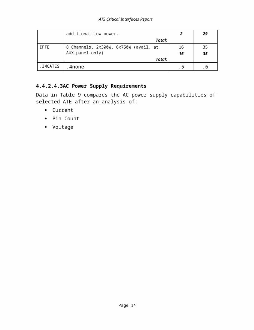
•
ATS Receiver / Fixture Diagram
Rack-Mounted Instruments and BenchtopEquipment* Power Supplies * Data Comm.* Electronic Leads * Controllers* Frequency Standards * Monitors* Synthesizer * Keyboard* Spectrum Analyzers
Rack-Mounted Instruments and BenchtopEquipment* Power Supplies * Data Comm.* Electronic Leads * Controllers* Frequency Standards * Monitors* Synthesizer * Keyboard* Spectrum Analyzers
Interface Planes1 VXI Instrument Front Panels2 Receiver/ITA Mass Quick Disconnect3 ITA/UUT Cable or Edge-Card Interface4 Mainframe Rear Bulkhead5 Rack-and-Stack Instrument Front/Rear Panels
Interface Planes1 VXI Instrument Front Panels2 Receiver/ITA Mass Quick Disconnect3 ITA/UUT Cable or Edge-Card Interface4 Mainframe Rear Bulkhead5 Rack-and-Stack Instrument Front/Rear Panels
Cable AssembliesA VXI Instrument to VXI Instrument JumperB VXI Instrument to ReceiverC Mainframe Rear Bulkhead to VXI InstrumentD Mainframe Rear Bulkhead to ReceiverE Fixture Jumper To/From Test SystemF Fixture Jumper To/From UUTG Fixture Interface to UUT InterfaceH UUT Interface of the Fixture to UUT InterfaceI Rack-and-Stack Instrument to Rack-and-Stack InstrumentJ Mainframe Rear Bulkhead to Rack-and-Stack Instrument
Cable AssembliesA VXI Instrument to VXI Instrument JumperB VXI Instrument to ReceiverC Mainframe Rear Bulkhead to VXI InstrumentD Mainframe Rear Bulkhead to ReceiverE Fixture Jumper To/From Test SystemF Fixture Jumper To/From UUTG Fixture Interface to UUT InterfaceH UUT Interface of the Fixture to UUT InterfaceI Rack-and-Stack Instrument to Rack-and-Stack InstrumentJ Mainframe Rear Bulkhead to Rack-and-Stack Instrument
FixtureFixture
Unit Under Test
Fixture Test InterfaceEngagement Assembly
Receiver
VXI MainframeVXI Mainframe
Power Supply
Backplane
Cooling System
Cable Tray
VXI InstrumentModules
Embedded PCMCIA Modules, Active Eurocard Modules, or ActiveCircuitry (e.g., switching, termination, filtering, buffering)
A
B
C D
E F
1
2
3
4
I
G
H H
J
ats_rf_i Figure 18Figure 18 Example Receiver/Fixture ATS Interfaces
Page 22
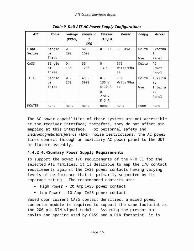
ATS Critical Interfaces Report
4.4.3.2Subelement ReviewIn order to address the receiver/fixture requirements, the interface was partitioned into subelements that were manageable for our review and selection process. These subelements are shown in Figure 19 and in Figure 20 as follows:
· Fixture Connector/UUT Cabling· Fixture Enclosures/Internal Structures· Fixture Frame Mechanisms· Receiver/Fixture Connector Contacts and Modules· Receiver Mechanisms· Receiver/Fixture Pin Map
The receiver/fixture is the overall assembly that connects the test system with the UUT. It is assembled from two major subassemblies as shown in Figure 19; the receiver (which is part of the ATS and is typically mounted to the front of the test system), and the fixture, that is uniquely designed as part of a specific TPS to adapt a UUT to the ATS.
Receiver/Fixture CriticalInterface System
Fixture
Test System Chassis& Instrumentation
Receiver
Fixture Frame
Fixture Enclosure and UnitUnder Test (UUT) Interface
Receiver / Fixture Basic Structure
rf_basic Figure 19 Figure 19 Receiver/Fixture Basic Elements
Both the receiver and the fixture are modularized further into a fixture frame, contact module, and contacts, as shown in Figure 20, to support the mechanical and electrical connection. Typically, the test system requires the use of three types of electrical connections:
Page 23

ATS Critical Interfaces Report
· Signal connections for digital and general low level signal applications· Power connections to interface high amperage/voltage (20-50A) level signals· Coax connections for RF signals. To support and house the RF coax contact pins,
a variety of receiver/fixture contact modules are employed
4.4.3.3Requirements and Alternatives Considered
4.4.3.3.1Receiver Trade-OffsThe importance of the RFX begins at the measurement instrument input or output connector. From this point, signals must be connected to the receiver through various means. This constitutes the front-end of the ATS.The architecture of the RFX varies with the application of wiring techniques, electrical switches, the signal type, the functional needs of the UUT, and the mechanical fixture interface requirements. This may be further driven by the user’s desire to have greater flexibility and capabilities to support multiple UUT requirements. In contrast, economics has forced the wide majority of users to choose the lowest cost solution, one that employs no interface at all. This option connects the UUT directly to the Resource by means of electrical wiring. For many, and specifically Government support agencies, this is not practical given certain production or repair environments that demand numerous set-ups, consistent signal integrity, and high volume interface cycling.
Receiver ConnectorContact Pin
Receiver ContactModule
Receiver Alignment &Closure Subassembly
ReceiverFixture Frame withFixture Modules and Contacts
Fixture Connector Contact Pin
Fixture ContactModule
R/F Sub Components
rf_sub Figure 20 Figure 20 Receiver/Fixture Subcomponents
After establishing a need for an interface, the test engineer must further assess what type of interface is best. This may include consideration of a switch matrix and the wire length between the elements. Switch matrices are applied to redirect signals to and from the
Page 24
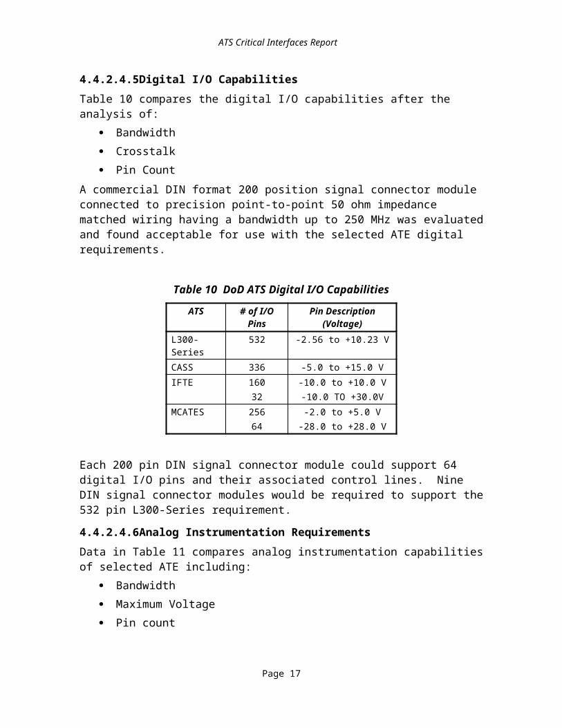
ATS Critical Interfaces Report
UUT and Test Resources being used. This optimizes the instrument use and reduces the number of pin connections to the UUT. Wire length is a more predominate factor in digital applications in which propagation delays can limit the bandwidth of digital measurements. Special impedance matched cabling is available to counteract these concerns.
4.4.3.3.2Receiver - Resource Interface AlternativesAssuming the test engineer integrates a commercial test system and the need for an interface is established, Figure 21 details a number of interface approaches that can be used.
.7
Receiver Approaches
3. Typical Integrated Approach1. Current or Typical Interface
Instruments
ReceiverModule
FixtureModule
2. Dedicated Connector Interface
Instruments
FixtureModule
ReceiverModule
Dedicated Connector
Note The ReceiverModule is attached
directly to theinstrument module as
the edge cardconnector.
InstrumentModule
ReceiverModule
SwitchModule Fixture
Module
4. Integrated Switch-Receiver Approach
ReceiverModule
FixtureModule
Instruments
Switching
rcv_app Figure 21Figure 21 Receiver Interfacing Approaches
The approaches identified in Figure 21 provide advantages and disadvantages that can be traded-off by the user. The following paragraphs outline these aspects.
8. The Current or Typical Interface approach represents the lowest cost solution and is the most flexible. Although the receiver configuration is fixed, the instrumentation and wiring can be adjusted easily by the user to the application. This recognizes that any change or substitution may affect the TPS application.
9. A Dedicated Connector Interface is similar to the current approach but applies a shortened wire length and EMI shielding scheme. This primarily benefits users who demand high signal integrity and are not pin limited. Because of its dedicated instrument to receiver contact module interface, it is one of the most
Page 25

ATS Critical Interfaces Report
inflexible approaches offered. This constrains the user to define a fixed configuration at the start and stay with that approach through the test system’s life. The receiver must be a special design to accommodate the connector interface and act as an alignment fixture for the connector.
10. The Typical Integrated Approach employs a switch module to facilitate switching between the instrument and receiver. This enhances the flexibility of the test system in routing signals to and from the UUT with a minimum number of pin interfaces. Although more expensive than the previous approaches, it affords more capability to the user than any other approach.
11. The Integrated Switch-Receiver Approach combines instrumentation, switching and a receiver module on a single card assembly. This approach is often applied by digital ATE test systems that require a full signal pin map of the receiver and which benefit from the dedicated switch and minimum wire length. However, like the Dedicated Interface Connector approach, it is inflexible to change without disrupting the receiver configuration. In addition, the receiver must now serve as a support rack for the card assembly.
The receiver is the common element of any ATS approach, that accepts a wide variety of connector designs in support of unique UUTs. Because of its commonality with the fixture, the receiver must be capable of accepting the highest pin configuration of any of the fixtures being supported. Specific elements of the receiver, as shown in Figure 22, include:
· Receiver Alignment / Fixture Holding / Operating Mechanism· Receiver Contact Module· Manual Operating Handle
Receiver Contact Module
Manual Operating Handle
Alignment / Fixture Holding / Operating Mechanism
Receiver Sub-Element
rcv_sub Figure 22 Figure 22 Receiver Subelements
Page 26
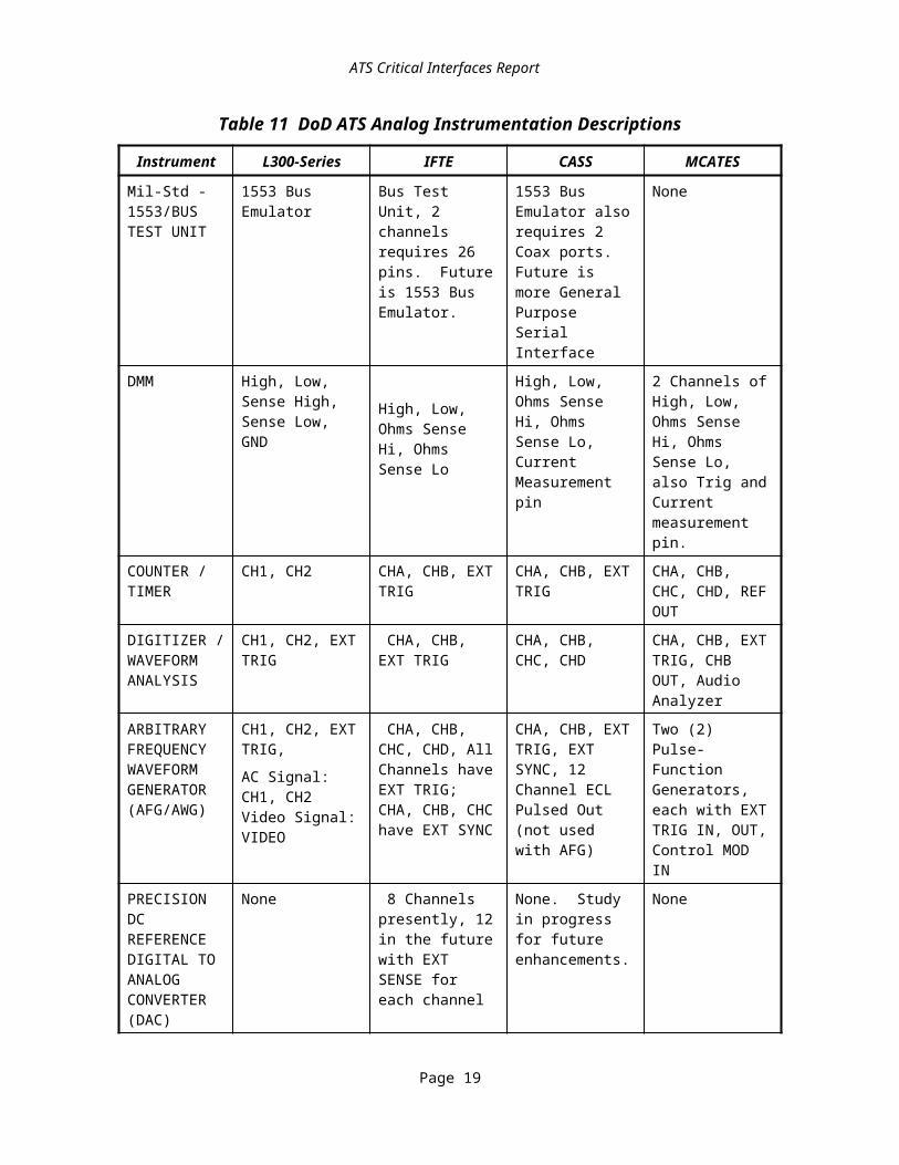
ATS Critical Interfaces Report
4.4.3.3.2.1Receiver MechanismsThe Receiver is offered in various sizes to accommodate the needs of the user and associated test system. Although this drives the dimensions of the receiver, as well as the number of contact modules and pins that can be accommodated, it does not change the basic mechanical concept used.The various concepts for mechanically mating the fixture connectors to the receiver connectors are shown in Figure 23.The differences shown involve either the pin contact methods or the mechanical alignment and closure subassembly. The MAC Panel Series 157 receiver (Figure 23 (A)) uses a CAM action to move the fixture vertically until contact is made by the pin with the spring-loaded tab connector. This permits zero-insertion force of the fixture into the receiver and a minimum amount of CAM action force to press the contact pins of the fixture against the receiver connector tabs. These types of assemblies were used heavily in an earlier period of interface development.
(B) MAC Panel 120 Series Claw Action Receiver
(A) MAC Panel 157 Series CAM Receiver
(C) Virginia Panel 90 Series Inclined Plane/CAM
CamActuator
Receiver FixtureFixture Receiver
Claw
(D) AMP MTI Series Ball Lock/Gear Receiver
Receiver
Disengaged Cam Actuator
Fixture
Engaged
Fixture
Receiver
Ball-lockPiston Actuator
Comparison of Mechanical Interfaces
rcv_comp Figure 23Figure 23 Example Mechanical Interface Receivers
The typical receiver used today implements either the Claw Lever Linkage identified in Figure 23 (B) or the Inclined Plane/CAM actuator design shown in Figure 23 (C). Both apply a picture frame fixture design with a perimeter roller assembly, shown in Figure 23 (D). This approach utilizes a mechanical linkage assembly to apply lever action of the operator handle to the CAM or receiver claw of the alignment and closure assembly.
Page 27

ATS Critical Interfaces Report
Either the two slide plates of the VPC 90 series or the four receiver claws of the MPC 120 series are used to engage four rollers of the fixture frame. This engagement initially aligns and holds the fixture onto the receiver until the handle is actuated to pull or push the fixture from the receiver. Other mechanisms are employed to lock the fixture into position and electrically indicate the existence or absence of a fixture in the receiver. The latter serves as a safety feature.Five other designs offered by the industry are the IFTE Hughes Gold Dotª Interface, Virginia Panel Company Modular Interface Technology (MIT) Connecting System, TTI Testron VG Series, GDE and AMP HDZª Compression Interface, and the AMP Inc. Modular Test Interface System (MTIS). These unique approaches to a receiver/fixture design accommodate certain features that enhance either cycle life, cost effectiveness, or performance. The following provides further description of the designs.
4.4.3.3.2.2Receiver Framework DesignOne aspect of receiver design that impacts life-cycle durability and dictates the scaleability of the fixture is the framework loading concept. A traditional receiver design, that is implemented more widely (e.g., VP 90 Series, MPC 120 Series, and TTI Testron VG Series), utilizes a perimeter framework to engage the fixture to the receiver. This transfers the load of the pull or push from the mechanism on the outside framework to the modules and in turn to the contacts that are encountering the force as resistance. Whereas the scaleable architecture used by the VPC MIT and AMP MTI receiver designs distribute the load over segmented pull/push points, the latter primarily applies this concept to allow smaller footprint fixtures to be attached to a wider footprint receiver, thus the term scaleability. As an added benefit, the load is distributed more evenly over the fixture frame. This reduces bowing, a fundamental problem for receivers. Bowing occurs when the fixture Frame or Modules flex under the force caused by engagement resistance of the contacts. The greater the separation the more acute the problem.The impact of bowing on the interface is degraded signal transmission performance. This occurs when there is a reduced amount of contact surface area between adjoining pins. Long term problems include accelerated surface area wear, added resistance to signal path, and a reduced fixture life cycle. To counteract this effect, traditional receivers have included a robust metal structure to reduce bowing under significant force and have proved viable for programs such ARINC 608A, CASS, and Modular Automatic Test Equipment (MATE).
4.4.3.3.2.3Receiver Mechanical AdvantageThe lever action converts the force applied at the operator handle to the actuator and then to the fixture frame. This is defined as mechanical advantage of the receiver, which represents the ratio of force at the fixture to that placed on the operator handle. This factor is important given the pressure needed to mate a large number of connectors, where each contact (e.g., Power - 2 lbs.; or Signal - 1 ounce) requires mechanical force to engage and disengage the contact. As an example, the MAC Panel Series 75 receiver offers a mechanical advantage of 43:1. Assuming a 1000 signal pin interface that requires 4 ounces per contact, a 250 pound force must be exerted on the fixture to close all contacts.
Page 28

ATS Critical Interfaces Report
This receiver will only necessitate 6 pounds of force to be applied to the operator's handle. The VPC 90 series receiver on the other hand has an 8:1 mechanical advantage that dictates 31 pounds of force be applied.Where coax and power pins are employed demanding as much as 6-12 ounces of pressure per connector, this force can dramatically increase. In some military programs, the force required on a single tier receiver is 1200 pounds, which requires an operator using those same systems, to apply 28 to 150 pounds of force at the handle. To increase mechanical advantage, suppliers usually apply handle extensions as is done on the CASS program to reduce the force within the ability of an operator to perform the effort.Over the years, manufacturers of connectors have continued to reduce the mechanical resistance incurred in closing each contact. This is complemented by the improvement in reliability and signal integrity over a higher number of cycles. More detailed discussion of the connector contact pin will follow in subsequent paragraphs.
4.4.3.3.3Fixture Product Design AlternativesThe fixture, shown in Figure 24, serves as a mechanical and electrical link between the UUT and the receiver of the test system. It is composed of the:
· Connector Contact Pins· Contact Modules· Enclosure· Fixture Frame· UUT Interface
Fixtures, much like the receiver, accommodate a variety of adaptations to interface the UUT to the test system. In general, the industry has identified four basic types used that are characterized by how they connect to the UUT. They are:
· Bed of Nails Fixture· Box/System Cable Interface Fixture· Device Adapter Board (DAB)· Printed Circuit Plug-in Fixture
Page 29

ATS Critical Interfaces Report
Fixture Frame
Fixture Connector Module
Enclosure
UUT CableConnector
UUT PCBConnector
Basic Fixture Design
fix_basic Figure 24
Figure 24 Fixture Basic Design
4.4.3.3.4General RequirementsGeneral requirements for the receiver/fixture were derived from many sources representing both general industry needs, Government-commercial interests, Government open-system directives, industry technology trends, NSIA recommendations, Government/Aerospace test requirements (functional test requirements), and Test Industry/Connector/Packaging Standards. The CIWG reviewed the widest spectrum of requirements and interest to assure that worst case needs were understood. These requirements were used to define an extreme envelope that the solution may encounter. The review process determined whether standards or products could meet those envelopes or were limited in their respective application.
4.4.3.3.4.1Design General ObjectivesThe following design objectives were employed to stimulate and direct the CIWG’s goal towards defining a more detailed specification. These objectives reinforce what has been advocated previously.
· Develop an open system commercial connector/mechanism standard that: 12. Is widely accepted by industry with multi-vendor sources.13. Has established footprint/design definitions.14. Offers a full range of options to meet signal, power, and coax
requirements.
Page 30

ATS Critical Interfaces Report
15. Supports high cycle life performance and maintainability.16. Is available today in volume production, and in its early product life-
cycle phase.· Provide a scaleable receiver/fixture with a modular framework design that permits
the receiver to be incrementally augmented through bolt-on features for expandability while maintaining downward compatibility with any smaller fixture increment.
· Establish a common connector footprint (slot) specification that offers multi-vendor sources but flexible enough to support a wide variation of contacts and evolve with changing test needs.
· Define a minimum standard I/O configuration that supports fixture transportability, but does not hinder flexibility or expansion.
· Define a minimum standard fixture family, kit designs, and common component/wiring.
· Supports portable and 19Ó rack integration employing hinged down rear access and standard mounting/footprint/extension standards.
4.4.3.3.4.2Design Performance ObjectivesPerformance specifications were also applied. These specifications were developed from the IFTE, CASS, and CASS missile test system requirements. These parameters were defined as worst case needs that the RFX must meet in its full configuration. Although these requirements must be ultimately addressed, it was desirable that these capabilities be modular in their implementation, thereby permitting a minimum subset to be applied, while maintaining upward compatibility on receivers dictating greater requirements. Further discussions of the design performance objectives follow.
4.4.3.3.4.3Receiver/Fixture Building Block I/O RequirementsThe varying minimum to maximum needs of the Government have dictated that the architecture of the receiver support three levels of integration support. To facilitate this requirement, the receiver/fixture design must not only be expandable in its size to accommodate a larger number of I/O, but must also support direct migration of the smaller size fixture. A third factor affecting the connector definition is the pin map requirements that may further impose a pin position within the RFX. To permit scaleability of the interface a minimum building block pin map must also be defined. This pin map design is further impacted where digital channel cards and switch/matrices are employed. In effect, the building block pin map must support both pin performance/density requirements and be upward pin map compatible to support direct migration of the smaller size fixture onto a fully populated receiver (e.g., a four slot fixture would directly plug into a 24 slot receiver without modification). The building block of I/O performance that must remain upward compatible with connector configuration and contact performance must be identified against current Government ATS needs and address the three levels of capability. The three levels and their respective I/O definitions are described in Table 17, Table 18, and Table 19.
Page 31

ATS Critical Interfaces Report
Table 17 Worst Case - High End Requirements
Connector Configuration
Signal Contacts 2400 Contacts, 0 - 2 Amp
Power Contacts 96 Contacts, 2-20 Amp
Coax Contacts Low RF 144 Contacts, DC - 1.2 GHz
Coax Contacts High RF 24 Contacts, DC - 26.5 GHz
Table 18 Typical - Mid Range Requirements
Connector Configuration
Signal Contacts 1200 Contacts, 0 - 2 Amp
Power Contacts 48 Contacts, 2-30 Amp
Coax Contacts Low RF 72 Contacts, DC - 1.2 GHz
Coax Contacts High RF 12 Contacts, DC - 26.5 GHz
Table 19 Basic - Low End Requirements
Connector Configuration
Signal Contacts 600 Contacts, 0 - 2 Amp
Power Contacts 24 Contacts, 2-30 Amp
Coax Contacts Low RF 48 Contacts, DC - 1.2 GHz
Coax Contacts High RF 12 Contacts, DC - 26.5 GHz
4.4.3.3.4.4Receiver/Fixture Connector RequirementsThe electrical I/O requirements of the Government ATS demand scaleable, overlapping connector pin performance characteristics, that trade-off pin performance against I/O bandwidths (e.g., low power of 10 amps for 30% more density versus high power for 20 amps). To facilitate this requirement the receiver/fixture connector module design must address the overall I/O connector pin electrical characteristic's bandwidth and then relate that to the quantity of pins. The following tables summarize the contact types required to span the performance envelope of the four ATE families reviewed. A third factor affecting the connector definition is the pin map requirements that further impose a pin type/position on the RFX. To permit scaleability of the interface, a minimum building block pin map has to be defined. Tables 20-24 contain the overall DoD contact requirements.
Page 32

ATS Critical Interfaces Report
Table 20 Signal Contact Requirement
Characteristic Requirement
Operating Voltage 300 VDC Max
Operating Current 2.0 Amps DC Continuous
Contact Resistance 10 milliohms Max
VSWR 1:1.09 - 1:1.10 @ 200 MHz
Frequency Response LE +/- 1.0 dB to 100 MHz
LE +/- 3.0 dB to 500 MHz
Characteristic Impedance 75 +/- 5 Ohms
Insulation Resistance 5.0 x 10⁹ Ohms Min
Capacitance 10 picofarads Max
Reliability 25,000 Engagement Cycles
Footprint 0.025" square pins on 0.1" centers arranged
in two row by 25 pin multiples (e.g., 2x25,4x25,
2x50,4x50,etc) and supports mass terminated
ribbon type cables.
Mating Force 2.0 ounces max
Table 21 High Power Contact Requirement
Characteristic Requirement
Operating Voltage 250 VDC Max
Operating Current 20 amps DC Continuous
Contact Resistance 6 milliohms Max
Insulation Resistance 5.0 x 10⁹ Ohms Min
Capacitance 10 picofarads Max
Reliability 25,000 Engagement Cycles
Footprint 0.144" round pins on 0.255" centers
arranged in a staggered two row arrangement
Mating Force 24 ounces max
Page 33

ATS Critical Interfaces Report
Table 22 Low Power Contact Requirement
Characteristic Requirement
Operating Voltage 250 VDC Max
Operating Current 10 amps DC Continuous
Contact Resistance 8 milliohms Max
Insulation Resistance 5.0 x 10⁹ Ohms Min
Capacitance 6 picofarads Max
Reliability 25,000 Engagement Cycles
Footprint 0.053" diameter pins on 0.150" centers arranged
in staggered three row arrangement
Mating Force 16 ounces max
Table 23 Low RF Coax Contact Requirement
Characteristic Requirement
Frequency Bandwidth DC - 1.2 GHz
Operating Voltage 150 VAC, RMS
Contact Resistance 10 milliohms max
VSWR 1:0.70 - 1:1.74 (GHz)
RF Insertion Loss 0.03Ãf GHz
RF Leakage -90 dB @ 2.5 GHz
Contact Resistance Center contact; straight 6.0 milliohms max
Characteristic Impedance 50 +/- 2 ohms
Insulation Resistance 1000 Mohms min
Capacitance 15 picofarads max
Material/Plating Outer 360 Brass 30µ inches Gold over 50µ inches Nickel
Center 360 Brass 30µ inches Gold over 50µ inches Nickel
Footprint Sockets/ pins on 0.255" centers arranged in a staggered
two row arrangement
Reliability 5,000 Engagement Cycles
Mating Force 2 lbs. max
Page 34

ATS Critical Interfaces Report
Table 24 High RF Coax Contact Requirement
Characteristic Requirement
Frequency Bandwidth DC - 26.5 GHz
Operating Voltage 250 VAC, RMS
Contact Resistance 10 milliohms max
VSWR 1:1.04 - 1:1.06 (GHz)
RF Insertion Loss .03Ãf GHz
RF Leakage -90 dB @ 2.5 GHz
Contact Resistance Center contact; straight 3.0 milliohms
Characteristic Impedance 50 +/- 2 ohms
Insulation Resistance 5000 Mohms min
Capacitance 10 picofarads max
Reliability 5,000 Engagement Cycles
Mating Force 3 lbs. max
4.4.3.4Receiver/Fixture Recommendations and Rationale
4.4.3.4.1Subelement ReviewThe RFX task group identified, reviewed and weighed various Government and commercial architectures. The group was made up of industry and Government representatives involved in the manufacturing, integration, and use of the RFX.In order to address the receiver/fixture requirements, the interface was partitioned into five previously described subelements that were manageable for our review and selection process. These subelements are as follows:
· Fixture Connector/UUT Cabling· Fixture Enclosures/Internal Structures· Fixture Frame Mechanisms· Receiver Mechanisms· Receiver/Fixture Connector Contacts and Modules· Receiver/Fixture Pin Map
To review each subelement and weigh the available candidates, a weighting process was established. A list of attributes was developed as follows:
· Actuation - This factor is used to measure the relative mechanical performance of the receiver/fixture mechanism; i.e., its ability to mate effectively while handling a large number of contacts.
Page 35

ATS Critical Interfaces Report
· Backward Compatibility - This factor is the consideration of how well the interface supports previous versions of itself or of other interfaces of the same category.
· Commercial Acceptance - This factor indicates whether items that meet the interface type are available as a commercial item. It could include delivery time, how many products currently meet the interface, and the stability of the item in its present configuration.
· Cost - This factor considers the cost in both time and dollars to procure and support the product relative to alternatives.
· Ease of implementation - This factor considers the level of difficulty to provide the interface for the general ATS architecture.
· Implementation Status (Availability) - This factor weighs the maturity of the interface element and the number of commercial sources or custom sources that supply and will continue to supply the interface. Considered in this factor is the issue of obsolescence.
· Insertion Force - This factor is used to compare the relative insertion force required to mate connector modules.
· Level of Applicability (i.e., factory/depot/field) - Direct relationship of the interface to reducing TPS re-host costs and increasing interoperability within the scope defined by this effort.
· Maintainability/Supportability - These are the relative costs associated with keeping the product functional. They include product life cycle maintenance costs, calibration costs, repair, and replacement costs.
· Mass Termination - This factor is used to compare connector module support for mass termination.
· Modularity - This factor is used to compare the relative modularity of mechanism candidates.
· Open/Closed Product - Level of openness of a product to allow support by multiple vendors. For example, is the product supported by an open commercial standard that anyone with the capability can develop products to, or is it proprietary?
· Performance - This is a measure of functional ability of the interface. Attributes such as throughput, rates, accuracy and error correction are considered.
· Producibility - This factor measures the relative time and cost associated with manufacturing the interface.
· Reconfigurability - This factor considers the potential for the interface to evolve with changing test needs.
· Reliability - This is a relative measure of how often the product fails either by actual physical break down or functional failures.
Page 36

ATS Critical Interfaces Report
· Scaleing - This factor is used to compare the ease of scaling the mechanism candidates up or down depending on TPS requirements to keep fixturing cost to a minimum.
· Weighting Factor - This factor measures the relative importance of the mechanism attributes.
Each candidate for a subelement is judged against each ranking factor and given a score from 0 to 10 with 0 meaning not applicable and 10 meaning the most applicable. Each ranking factor is also assigned a weight from 1 to 100 percent that describes its relative importance to the TPS transportability and re-hostability problem. The final ranking value for each candidate is obtained by multiplying the score for each ranking factor by its assigned weight and then summing the ranking factors. From these rankings, recommendations are made for implementation. Note that each subelement does not utilize the complete list of weighting factors presented above, but only those deemed relevant to that subelement.
4.4.3.4.2Connector Review and Weighting ProcessThe connector/module subelement of the RFX is the most important of the subelements. The connector/module houses and electrically mates the signal paths between the ATS and UUT. It must also identify with many of the design performance requirements previously defined. The specific parameters that were used to evaluate each connector were discussed in an earlier section. From this an outcome and selections were made.
4.4.3.4.2.1Connector/Module Review CandidatesThe review considered all existing Government and commercial receiver/fixture connector and module candidates. These included:
· AMP HDZ Product· ARINC 608A· CASS· Commercial Available Spring
Probe· Eurocard DIN/ MIL-C-179/180
· GDE Systems· IFTE· MAC Panel 120/64 Series· MATE· Test Technology Inc.· Virginia Panel 90 Series
describes various connector/modules reviewed for RFX. Weighting factors for each parameter were established based upon their relative importance to the solution. These values are shown at the bottom of the chart and factored into the total outcome for each connector/module product design.
Page 37

ATS Critical Interfaces Report
Table 25 Receiver/Fixture Connector Product Design Comparison
.8 .9 .10 .11 .12 .13 .14 .15 .16 .17 .18 .19 .20 .21 .22
.23CASS .24 .25 .26 .27 .28 .29 .30 .31 .32 .33 .34 .35 .36 .37.38Signal .395 .405 .415 .429 .437 .442 .451
0.467 .478 .487 .495 .507 .513 .526.
08.53Power .545 .555 .565 .579 .587 .592 .609 .617 .628 .637 .641
0.657 .665 .676.
40.68Coax .695 .705 .715 .729 .737 .742 .751
0.767 .775 .787 .791
0.8010
.815 .826.40
.83IFTE .84 .85 .86 .87 .88 .89 .90 .91 .92 .93 .94 .95 .96 .97.98Signal .991 .100
1.1011
.1028
.1033
.1042
.1056
.1062
.1071
.1089
.1091
.1102
.11110
.1123.22
.113608 .114 .115 .116 .117 .118 .119 .120 .121 .122 .123 .124 .125 .126 .127.128Signal .129
4.130
4.1311
.13210
.1337
.13410
.13510
.1367
.1378
.13810
.1394
.1409
.1413
.1426.38
.143Power .1444
.1455
.1466
.14710
.1487
.14910
.15010
.1517
.1525
.15310
.15410
.1559
.1565
.1577.26
.158Coax .1594
.1605
.1616
.1628
.1637
.16410
.16510
.1667
.1675
.1687
.16910
.17010
.1715
.1726.92
.173MATE .174 .175 .176 .177 .178 .179 .180 .181 .182 .183 .184 .185 .186 .187.188Signal .189
4.190
5.1918
.1927
.1937
.1942
.19510
.1968
.1978
.1987
.1995
.2005
.2013
.2026.04
.203Power .2044
.2055
.2068
.2077
.2087
.2092
.21010
.2118
.2125
.2137
.21410
.2156
.2165
.2176.28
.218Coax .2194
.2205
.2218
.2228
.2237
.2242
.22510
.2268
.2275
.2287
.22910
.2309
.2315
.2326.50
.233DIN .234 .235 .236 .237 .238 .239 .240 .241 .242 .243 .244 .245 .246 .247.248Signal .249
10.25010
.25110
.2529
.2537
.25410
.25510
.25610
.2579
.2589
.25910
.2608
.2619
.2629.36
.263Power .26410
.26510
.26610
.2678
.2687
.26910
.27010
.27110
.2729
.2739
.27410
.2756
.2765
.2779.02
.278Coax .27910
.28010
.28110
.2829
.2837
.28410
.28510
.28610
.2879
.2889
.28910
.2908
.2915
.2929.20
.293TTI .294 .295 .296 .297 .298 .299 .300 .301 .302 .303 .304 .305 .306 .307.308Signal .309
6.310
6.3113
.3126
.3134
.3144
.31510
.3168
.3178
.3186
.3195
.3205
.3213
.3225.60
Page 38

ATS Critical Interfaces Report
.323Power .3246
.3256
.3263
.3276
.3284
.3294
.33010
.3318
.3325
.3336
.33410
.3356
.3365
.3375.84
.338Coax .3396
.3406
.3413
.3429
.3434
.3444
.34510
.3468
.3475
.3486
.34910
.35010
.3515
.3526.30
.353VPC90/MPC64
.354 .355 .356 .357 .358 .359 .360 .361 .362 .363 .364 .365 .366 .367
.368Signal .3696
.3706
.3712
.3727
.3737
.3748
.37510
.3768
.3778
.3787
.3795
.3807
.3813
.3826.36
.383Power .3846
.3856
.3866
.3877
.3887
.3898
.39010
.3918
.3925
.3937
.39410
.3957
.3965
.3976.96
.398Coax .3996
.4006
.4016
.4027
.4037
.4048
.40510
.4068
.4075
.4087
.40910
.41010
.4115
.4127.08
.413GDE “Pinless”
.4144
.4153
.4162
.4178
.4186
.4195
.4207
.4215
.42210
.4238
.4247
.42510
.42610
.4275.86
.428Spring Probe
.4298
.4304
.4318
.4326
.4337
.4345
.4356
.4369
.43710
.4388
.4395
.4405
.4419
.4426.78
.443Compression
.4449
.4453
.4467
.4478
.4485
.4494
.4507
.4515
.4525
.4538
.4547
.4559
.4569
.4576.40
.458Weighting (%)
.45912
.46012
.46110
.46210
.46310
.4648
.4656
.4666
.4676
.4686
.4696
.4704
.4714
.472100
4.4.3.4.2.2Connector and ContactsFor the signal connector, the CIWG selected a ruggedized 200 position signal connector, that represents a Eurocard DIN standard derivative which has received MIL-C-179/180 certification under the broader MIL-C-55302 specification.There is no open specification for the contacts. The CIWG made no selection in this area. However, the following parts have characteristics that could satisfy Government test interface needs.
· Commercial Low Power Contact - 10 Amp (e.g., Virginia Panel P/N 610 115 112 and P/N 610 116 112).
· Commercial High Power Contact - 20 Amp (e.g., Virginia Panel P/N 610 110 129 and P/N 610 110 128).
· Commercial Low RF Contact - 1.2 GHz coax contacts (e.g., Virginia Panel P/N 610 103 115 and P/N 610 104 114).
· Commercial High RF Contact 26.5 GHz coax contacts.In Figure 25, there are illustrations of different connector module configurations.
Page 39

ATS Critical Interfaces Report
Low RF Module24 Position
Mixed Power Module16/28 Position
High RF Module12 Position
Signal Module200 Position
Selected Connectors
connectors Figure 25Figure 25 Connector/Module Configurations
These parts have a common footprint established around the signal DIN connector. New connector modules will be developed to house the high/low RF and power contacts. Commercial suppliers that currently provide similar connector modules have indicated they can meet the new common footprint requirements. A full description of each connector module is provided in the following paragraphs.
4.4.3.4.2.3Eurocard DIN StandardThe Eurocard DIN standard serves primarily to establish a signal pin contact definition and footprint standard for mechanical and performance requirements. The selected design is a ruggedized connector that has been qualified under MIL-C-179-20, 22, and 24 for the 96-200 pin, four row fixture connector; and under MIL-C-180-9 and -10, for the 96-200 pin, four row receiver connector. Figure 26 show details of this connector. The performance of the signal module permits high speed digital and low frequency analog to 250 MHz when used with 50 ohm impedance matched cabling. It is also used by two of the three interface suppliers extensively. It met the highest levels for open system, low cost, performance, commercial acceptance, and level of applicability, receiving more than 25% higher grade over any of the other connectors reviewed.Figure 27 and Figure 28 illustrate the design for the Eurocard DIN standard connector/modules for the receiver side and fixture side respectively. Further analysis is included in Table 26 and Table 27 to reflect companies offering equivalent or less durable products for the signal connector.
Page 40

ATS Critical Interfaces Report
.473
Connector Detail
SIGNAL
conn_dtl Figure 26
Figure 26 Signal Connector/Module Detail
Page 41

ATS Critical Interfaces Report200 Pin Receiver
200pinrv Figure 27
Action Pin Post Solder Post
Figure 27 Eurocard DIN Receiver Connector/Module Design Specification200 Pin Fixture
Solder PostsAction Pin Posts
200pinfx Figure 28Figure 28 Eurocard DIN Fixture Connector/Module Design Specification
Page 42

ATS Critical Interfaces Report
Table 26 Eurocard DIN Comparison - Part 1
General Pin AssembliesManufacturer # of
rows# of
positionsHousing Material UL Flammability
Classification
Operating Temperature
‘C
Material Plating Note 1 Note 2 Note 3 Pin Replaceability
AMP - HDI Connectors 2
3
4
20 - 150
75 - 405
100 - 684
Glass - filled Polyphenyles Sulfide 94V - 0
-65 to 125 Phosphor Nkl overall, Gold on contact areas, Tin or Gold on post
0.73
0.53
0.250
0.190
0.120
0.180
Vertical Pin Contact can be replaced w/o removing connectors from board
Berg Electronic Division
High Pin Count
3
4
96 - 450
160 - 588
Polyetherimide 94V-0
-65 to 105
(note 6)
Phosphor Bronze
Nkl overall, Gold on contact areas, Tin or Gold on Post
0.73
0.68
0.51
0.33
0.73
0.68
0.51
0.33
None Vertical Pin Contact can be replaced w/o removing connectors from board
Burndy HD 2
3
4
20 - 200
75 - 540
100 - 720
Polyphenylene Sulfide 94V-0
-65 to 125 Phosphor Bronze
Gold over Nkl with Tin or Gold on Post
0.73
0.53
0.68
0.40
0.20
Not Known
None Not Known
ELCO HD 2
3
4
60 - 200
96 - 405
100 - 684
Polyphenylene Sulfide 94V-0
-65 to 125 Copper Alloy
Gold over Nkl with Tin or Gold Flash on Post
0.73
0.53
0.25
0.73
0.61
0.53
0.18
0.13
None Vertical Pin Contact can Be Replaced without Removing Connectors from Board
ITT Cannon CHD 3
4
up to 225
up to 300
Not Known -65 to 125 Not Known
Not Known Not Known
Not Known
Not Known
Not Known
Teradyne High Density Plus
3
3
Modular
Modular
Polyester 94V-0 -55 to 105 Phosphor Bronze
Gold over Nkl with Gold Flash on Post
0.57 0.06 None Not Known
TRW, Inc. 2
3
60 - 180
105 - 300
Polyester Pin Assy; Polyphenylene Sulfide Rcpt Assy,
-65 to 125 Phosphor Bronze
Gold over Nkl with Tin on Post
0.53 Not Known
None Not Known
Page 43

ATS Critical Interfaces Report
4 128 - 400 both 94V-0
Table 27 Eurocard DIN Comparison - Part 2
Manufacturer Material Plating Contact Style Solder Tail Length
Pin Replaceability General Comments
AMP - HDI Beryllium Copper Gold over Nkl with Tin on Tails
Four Beams with large Radii for Maximum Contact
0.180
0.120
0.145
Contacts can be replaced without removing connector from board.
Connectors can be soldered using Vapor Phase re-flow technology.
Berg Electronics Division High Pin Count
Phosphor Bronze (note 7)
Gold over Nkl with Tin on Tails
Two Beams, two small dimples make contact
0.145
0.120
Contacts cannot be replaced without removing connector from board.
Connectors suspect to Vapor Phase re-flow soldering techniques, (note 4).
Burndy HD Phosphor Bronze Gold over Nkl with Tin on Tails
Two Beams staggered Tulip
0.180
0.135
staggered tails
Contact replacement ability doubtful.
Connectors can be soldered using Vapor Phase re-flow soldering techniques (note 4).
ELCO HD Copper Alloy Gold over Nkl with Tin or Gold Flash on Tails
Two Beams with Large Radii
0.180 Contacts cannot be replaced without removing connector from board.
Connectors can be soldered using Vapor Phase re-flow soldering techniques, (note 4).
ITT Canon CHD Not Known Not Known Not Known Not Known Contacts cannot be replaced without removing connector from board.
Connectors can be soldered using Vapor Phase re-flow soldering techniques (note 4).
Teradyne High Density Plus
Copper Alloy with Tri-metal Inlay
Gold inlay over Nkl
Two Beams Not Known Contacts cannot be replaced without removing connector
Receptacle requires Aluminum stiff every Fifth row for
Page 44

ATS Critical Interfaces Report
Manufacturer Material Plating Contact Style Solder Tail Length
Pin Replaceability General Comments
from board. Power (note 5).
TRW, Inc. Beryllium Copper Gold over Nkl with Tin Solder Tails
Not Known 0.180 Not Known Receptacles can be soldered using Vapor Phase re-flow soldering techniques (note 4).
Note 10.Compliant Pin Post LengthNote 11.Solder Post LengthNote 12.Right-Angle Solder Post LengthNote 13.Connectors are intermateable and interchangeable with AMP - HDI connectorsNote 14.Connectors are not intermateable and are not interchangeable with AMP - HDI connectors.Note 15.As of mid 1986, Berg listed a temperature range from -65 to 125 C in their advertising literature.Note 16.As of mid 1986, Berg listed Beryllium Copper 17410 Alloy as the material for their receptacle contacts.
Page 45
ATS Critical Interfaces Report
4.4.3.4.2.4Mixed Low/High Power Contacts and Connector ModuleThe use of the commercial Low/High power contacts and the connector module permit direct integration of existing CASS qualified contact technology to achieve maximum versatility and limited risk to meeting the Government ATS requirements. The CASS contact specification has been applied by multiple vendors to meet Government and commercial requirements. To facilitate use of the CASS power and coax contacts in the same footprint of the DIN 200 position connector module, the industry has offered to develop modules to support this requirement, as shown in Figure 29. The connector contacts are currently offered by Virginia Panel and MAC Panel. Other companies, such as HyperTac, TTI and AMP have expressed interest to do the same.
.474
20 AMP Power Pins
10 AMP Power Pins
Fixture Module
Receiver Module
Mixed Low/High Power Contacts
m200pwr Figure 29
Figure 29 Mixed Low/High Power Contacts and Connector Module Design
4.4.3.4.2.5Low RF Coax Commercial Contacts and Connector ModuleThe use of commercial Low RF coax contacts and the 24 position connector module permits direct migration of existing CASS qualified contact technology. The CASS contact specification has been applied by multiple vendors to meet Government and commercial requirements. To facilitate use of the CASS Low RF coax contacts in the same footprint of the DIN 200 position connector module, industry has offered to develop modules to support this requirement, as shown in Figure 30. The contacts are currently offered by Virginia Panel and MAC Panel. Other companies, such as HyperTac, M/A-COM and AMP have expressed interest.
Page 46
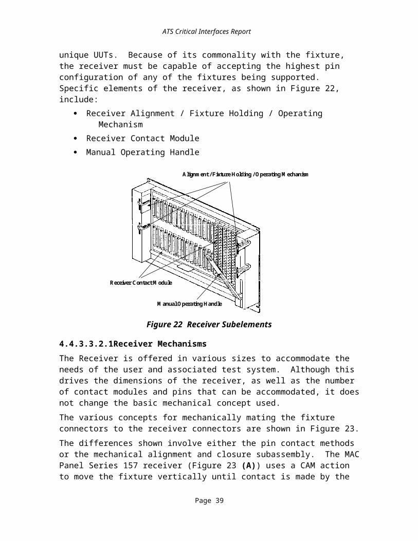
ATS Critical Interfaces Report
Low RF Coax Pins
Fixture Module
Receiver Module
Low RF Connector
m200amc Figure 30
Figure 30 Low Performance RF Coax Commercial Connector Module and Contacts
4.4.3.4.2.6High Performance RF Coax Contacts and Connector ModuleA commercial high performance RF blind-mate 26.5 GHz coax contact and a 12 position connector module extends the RF bandwidth capability of the interface. To facilitate use of the high performance RF coax contacts in the same footprint of the DIN 200 position connector module, industry has offered to develop modules to support this requirement, as shown in Figure 31. The contacts are currently offered by AMP and M/A-COM to meet the high end coax requirements.
.475
High RF Coax Pins
Fixture Module
Receiver Module
HIGH RF 200
h_rf200 Figure 31
Figure 31 High RF Coax Contacts and Connector Module
Page 47
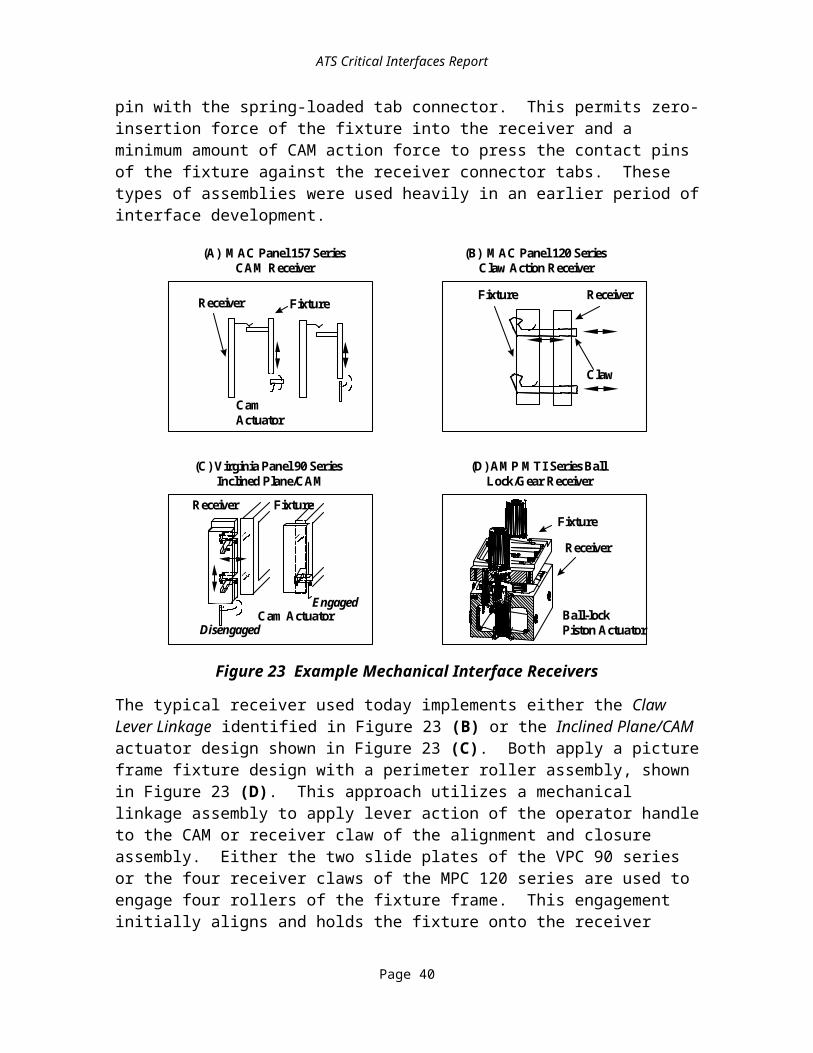
ATS Critical Interfaces Report
4.4.3.5Receiver/Fixture Mechanism Review and Weighting Process
4.4.3.5.1IntroductionThe receiver/fixture mechanism subelement of the RFX serves as the engagement system for pushing the connectors together to electrically connect the signal paths and then pulls them apart to break the contact. The mechanism houses/aligns the connector modules and their respective contacts. It also supports the fixture and identifies with many of the design performance requirements previously defined. Data in Table 28 represents the outcome of the review conducted and weighting process applied. The comparison chart reflects those receiver/fixture mechanism designs that were reviewed. The parameters used have been previously described.
4.4.3.5.2Receiver/Fixture Mechanism CandidatesThe review considered all existing Government and commercial receiver/fixture mechanisms and existing commercial candidates. These included:
· AMP HDZ Product· AMP Modular Test System· ARINC 608A· CASS· GenRad/Teradyne Electromechanical Systems· Hypertronics· IFTE· MAC Panel 64 Series· MAC Panel Intercoupler· MAC Panel Rotary· MATE· Test Technology Inc.· Virginia Panel 90 Series· Virginia Panel MIT Series
4.4.3.5.2.1Critical Issues of the Selection ProcessOf all the subelements of the RFX, the receiver/fixture mechanism proved to be the most difficult to review. This is primarily due to the competitive nature of the designs that reflect a specific companyÕs product advantages over a competitor’s. In some cases, this advantage extends to various patent rights. Design of a mechanism also requires a close relationship with the application and the connector design employed. Fifteen parameters were applied to the mechanism review of which three played a very significant role in determining the results. The three parameters were:
· Level of Applicability· Open System Design
Page 48

ATS Critical Interfaces Report
· Scaleability
4.4.3.5.2.2Level of ApplicabilityThe Level of Applicability is the degree of influence of the interface in reducing TPS re-host costs and increasing interoperability. In our review it appears only the commercial systems were able to reduce costs, primarily through advanced technology and use of available commercial technology, particularly as it applies to low-cost fixture wiring, assembly and production of the connector interfaces.
4.4.3.5.2.3Open System ArchitectureThe most critical factor affecting the selection of a system is the need to have a standard interface specification that represents an ÒOpen System ArchitectureÓ for the Government acquisition process. All of the designs including the Government agency systems, CASS, IFTE, MATE, and ARINC 608 mechanisms, are proprietary to the companies that supply the units. As such, all represent sole-source positions that counteract Government competition advocate policy. The task group has attempted to make this requirement essential for any selection. During the Phase I review each company involved was requested to consider opening its respective architecture to industry standardization. To date AMP and GDE have been the only companies informally expressing interest to do so. We have requested that those companies formally present their position in a letter to the subtask group.
4.4.3.5.2.4ScaleabilityTo support factory-to-field and down-sized requirements, it is essential that the ATS receiver/fixture solution provide a scaleable architecture. This serves to minimize costs of fixturing by scaling the fixture to meet only what is necessary to interface the UUT to the ATS (e.g., a cable assembly can be directly plugged-into the receiver without any fixture box being applied). This also permits an avionics board subcontractor to develop a compatible TPS for factory test and allow the Government to utilize that same fixture on the high-end depot tester without a full size configuration RFX. Such capability demands that the mechanism support engagement actuators at incremental points to pull smaller footprint fixtures into the receiver.
4.4.3.5.3Receiver/Fixture Mechanism ResultsThe outcome of the review indicated that although existing Government receiver/fixture mechanism supported the Government adequately, none provided the features that several of the commercial systems offered and none of the systems, Government or commercial, represented an Open System architecture. There is no open specification for the receiver/fixture mechanism, and so the CIWG made no selection in this area.Of the thirteen designs reviewed, the three most effective solutions were found to be commercial products, including:AMP MTIS..............................................................................Weighted average: 7.07
AMP MTIS received greater marks on performance, scaleability, and robust nature of the design, but did present higher relative costs and weight penalties.
Page 49

ATS Critical Interfaces Report
Hypertronics High Performance Connector System.................Weighted average: 6.55Hypertronics HPCS offers high density, lightweight and low costs, while suffering limitations to expand its architecture above 1000 pins.
Virginia Panel MIT..................................................................Weighted average: 6.13Virginia Panel MIT is similar to the Hypertronics system having the same pros and cons.
Weighting factors for each parameter were established based upon their relative importance to the solution. These factors are shown also at the bottom of the chart and factored into the total outcome for each product design.
Table 28 Receiver/Fixture Mechanism Product Design Review
AMP HDZ 9 3 1 7 7 8 5 8 5 5 10 4 10 3 5.70
AMP MTIS 6 10 1 8 9 8 8 8 10 10 8 10 6 10 7.07
GDE/VPC/MPC
CASS MATE 608A
5 4 1 7 4 8 10 8 10 8 8 4 5 10 5.45
Hypertronics 10 4 1 8 9 9 8 8 5 6 10 7 8 3 6.55
IFTE 1 2 1 3 1 3 4 8 10 1 8 4 1 10 3.09
MPC 64/VPC 90 6 6 1 7 6 9 10 8 10 9 8 4 6 10 3.09
MPC Intercouple 5 6 1 5 4 4 5 8 8 9 8 6 6 10 6.12
MPC Rotary 8 4 1 7 8 8 8 8 9 4 10 4 9 5 5.02
Teradyne/GenRad 3 4 1 4 3 3 5 8 10 3 8 3 1 10 6.08
TTI 6 6 1 7 9 9 8 8 8 7 8 4 7 10 3.93
VPC MIT 8 4 1 7 8 8 8 8 9 6 10 7 9 6 6.13
Weighting (%) 12 12 12 9 9 7 5 5 7 5 4 7 4 2 100
4.4.3.5.4Receiver/Fixture Mechanisms Long Term SolutionThe long term view of the subtask group is to establish an industry standard that provided an Open System architecture. This would necessitate either a one year period of industry
Page 50

ATS Critical Interfaces Report
meetings and consensus that would facilitate a design that multiple vendors could offer, or a willingness of one company to offer a design to the industry for adoption as a standard.To fully support the needs outlined earlier, we have provided a straw man design that is currently being reviewed by several vendors for commercial development and standardization. The design provides answers to standardization, TPS transportability from factory-to-field, scaleability, modularity, performance, and low-costs. It is the intent to encourage suppliers to consider development of this product that embraces features of the DIN Standard and AMP MTIS.Figure 32 is offered to illustrate the design. The architecture shown is a building block design that expands from a basic four slot fixture building block and twelve slot receiver footprint approach that can be easily assembled to facilitate larger footprints and connector requirements. The receiver building block that supports twelve connector modules can be scaled upward to a maximum of four blocks or 48 slots that can accommodate in two tiers 48 DIN connectors (9600 pins). The design can also accommodate various fixture sizes from the maximum of 48 slots to the smallest footprint of a four slot fixture. The smaller fixtures can be independently supported at any of 12 different positions on the receiver.The recommended configuration correlates to the three levels of ATS integration and pin-out requirements, as well as the modularity of the switch matrix. Although some analysis has gone into the definition of this configuration, it is desirable to further study these issues and include a more detailed design approach during the demonstration phases.
4.4.3.5.5Receiver/Fixture Mechanisms Short Term SolutionThe recommendation of the subtask group for the short term needs of the Demonstration Program is based upon results of the review and conformance of the products to the requirements of the Government. The AMP MTIS appears to possess the best features for supporting the RFX in the short term. Should AMP elect to make the system an Open System architecture it would remove any remaining issue that detracts from its selection. The primary features the MTIS offers are:
· Current compatibility with the DIN connector standard· Scaleability and modularity of its architecture· High performance connector modules
Page 51

ATS Critical Interfaces Report
.476
12 Slot Receiver
12 Slot Fixture
8 Slot Receiver
8 Slot Fixture4 Slot Fixture
24 Slot Receiver
24 Slot Fixture
Receiver / Fixture Design Specification
rf_design Figue 32
Figure 32 Receiver/Fixture Mechanism Design Specification Configuration
4.4.3.6Fixture Enclosures Review and Weighting ProcessThe fixture enclosure and Internal Packaging Structure subelement of the RFX serve as the structural/housing system for fixture connectors/modules and the supporting interfaces to the UUT. The fixture enclosure and Internal Packaging Structure provide direct wiring signal paths between the receiver of the ATS and the UUT. It typically supports any cable interfaces or printed circuit board mounting and secondary connectors necessary to interface to the UUT. In many instances the fixture is also used to house active and passive components that buffer, terminate, adjust, and/or any other support function that the ATS could not perform to test the UUT.The review considered how fixture designs are derived and what generally drove the design. Three basic applications were identified that are typically used in the field, including:
· A standard rectangular box for cable interfacing· A shelf design or standard rectangular box that supports printed circuit board
testing
Page 52

ATS Critical Interfaces Report
· A shelf support that supports direct plug-in of avionic modules or boxes. In some depot applications, vacuum fixtures are used to pull down boards on to a bed of nails (spring probes)
.477Data in Table 29 represents a comparison of candidate designs against the specific parameters that each fixture enclosure and Internal Packaging Structure design must meet. The parameters used were described in a previous section.
Weighting factors for each parameter were established based upon their relative importance to the solution. These factors are shown at the bottom of the table and factored into the total outcome for each product design.
Table 29 Fixture Internal Packaging Product Review Comparison Chart
Eurocard
VXI 6 10 10 6 9 10 8 8 10 8 9 8.48
VME 6 10 10 6 9 10 8 8 10 8 9 8.48
PC-104 3 4 10 6 5 3 3 6 5 6 3 5.04
Industry Pak 3 4 10 6 5 3 3 6 5 6 3 5.04
PCMCIA 3 6 10 6 8 8 4 6 3 6 1 6.02
Mil-Std
Type A 1 7 10 10 4 1 1 9 7 10 9 5.94
Type B 1 7 10 10 4 1 1 9 7 10 9 5.94
Weighting (%) 12 12 12 12 12 10 8 6 6 6 4 100
4.4.3.6.1Fixture Enclosure and Internal Packaging Structure Review CandidatesThe review considered all existing Government and commercial receiver/fixture mechanisms and existing commercial candidates. The internal packaging of fixtures were reviewed to build standardization within the fixture as well as external. This was intended to reduce proliferation, simplify design, assembly, sparing, and replacement parts of internal wiring and active component packaging/mounting. The specific designs reviewed by the group for fixture packaging were:
· Eurocard VXI and VME packaging
Page 53

ATS Critical Interfaces Report
· Industry-Pak· Mil-Std Type A and B packaging· PC-104· PCMCIA
4.4.3.6.2Fixture EnclosuresThe consensus of the group was that fixture enclosure designs can be standardized within certain restrictions of size and pin configurations, but required greater definition of whether active components were required and to what degree. Also, the footprint of the fixture enclosure is currently driven by the receiver footprint. If scaleability can be employed, then alternatives could be used, e.g., cabling that directly plugs onto the receiver without a fixture or a card adapter that converts Printed Circuit Board (PCB) edge to receiver mating interface that can be directly plugged into the receiver.
4.4.3.6.3Internal Packaging Review and Weighting Process.The outcome of the structural review indicated considerable benefits to the ruggedized Eurocard packaging architecture, employing the VXI/VME form factors. It is a well recognized packaging standard worldwide offering extensive products and vendor support. It met the highest levels for open system, low cost, performance, commercial acceptance, and level of applicability, receiving more than a 25% higher grade over any of the other products reviewed.The PC-104 and Industry Pak were reviewed, but were recognized to be limited to component packing on a board. The PCMCIA approach could be considered, but requires surface mount technology.
4.4.3.7Receiver/Fixture Pin Map EvaluationThe CIWG examined signal requirements of a variety of ATEs and compared these requirements to the capabilities of the connectors and contacts discussed in Section 4.4.3.4.2.2. Table 30 shows one possible configuration that could satisfy these requirements.To facilitate integrating ATEs with different levels of capabilities, the RFX must have a clearly defined connector module and contact configuration or pin map. The pin map configuration must also support a building block approach that can satisfy the low end requirements. The worst case requirements can be met by means of duplication. Figure 33 describes a possible receiver/fixture pin map. This pin map specification is preliminary and is expected to be reviewed as part of the Demonstration to verify performance and configuration needs. As shown, it reflects a basic building block structure that is incremented in four slot stages:
· Digital I/O, part A· Digital I/O, part B· Low frequency switch matrix I/O· Power
Page 54

ATS Critical Interfaces Report
P
O
W
E
R
SYN
RSL/DAC
P
O
W
E
R
24 23 22 21 20 19 18 17 16 15 14 13 12 11 10 9 8 7 6 5 4 3 2 1
DIGITAL
I/O
DIGITAL
I/O
DIGITAL
I/
O
DIGITAL
I/O
DIGITAL
I/O
DIGITAL
I/O
DIGITAL
I/
O
DIGITAL
I/O
RF
SWT
I/
O
1 - Fixed routing DC Power 1-6, Sense 1-6 (16 High, 29 Low power pins)2 - Matrix Universal I/O (96 low frequency signal pins)3 - Digital I/O 1-64 Channels (128-192 signal pins)4 - Digital I/O 65-128 Channels (128-192 signal pins)5 - Switched DC Power, Sense (16 High, 29 Low power pins)6 - Matrix I/O (24 low RF coax pins)7- RF Switch I/O (12 high RF coax pins)8 - Digital I/O 129-192 Channels (128-192 signal pins)9 - Synchro Resolver Simulator/ Indicator and Digital to Analog (DAC) Converters 1-12 (50-200 signal pins)10 - Matrix I/O (24 low RF coax pins)11 - Low Frequency Utility Switching (128-192 signal pins)12 - Digital I/O 193-256 Channels (128-192 signal pins)
13 - Fixed routing DC Power 1-6, Sense 1-6 (16 High, 29 Low power pins)14 - Matrix Universal I/O (96 low frequency signal pins)15 - Digital I/O 257-320 Channels (128-192 signal pins)16 - Digital I/O 321-384 Channels (128-192 signal pins)17 - Switched DC Power, Sense (16 High, 29 Low power pins)18 - Matrix Universal I/O (96 low frequency signal pins)19 - Digital I/O 385 - 448 Channels (128-192 signal pins)20 - Digital I/O 449-512 Channels (128-192 signal pins)21 - Matrix Universal I/O (96 low frequency signal pins)22 - Matrix I/O (24 low RF coax pins)23 - High Voltage Digital I/O 1-64 Channels (128-192 signal pins)24 - Digital I/O 513-536 Channels (128-192 signal pins)
UTIL
SWTCH
HVDIGITALI/
O
DIGITAL
I/
O
MTRXEPSI/O
MTRXEPSI/O
MTRXEPSI/O
MTRX
UI/O
MTRX
UI/O
MTRX
UI/O
MTRX
UI/O
Miscellaneous: (e.g. Serial, Interlocks) signal pins utilize spare pins in Digital I/O, DAC, Synchro, and UtilitySwitch modules.Pin Map view is as seen from the front of the receiver.
SWT
PWR
SWT
PWR
Pin Map
pin_map Figure 17Figure 33 Possible Receiver/Fixture Pin Map Configuration
Page 55

ATS Critical Interfaces Report
This same configuration is reiterated in Slots 5-8, 9-12, 13-16, 17-20, and 21-24, with exception that the first and third module of each set may vary based upon requirements. Two of the slots are spares and may be defined later or used on certain dedicated ATE for unique functionality.Based on the review of the L300-Series, CASS, IFTE, and MCATES capabilities, the pin map in Figure 33 should fully support all current Government ATS requirements in a single tier. Should additional capability be required beyond this level, a second tier providing 24 more slots can be accommodated as shown in Table 30. Because of the scaleability of the system, TPS developers may elect to use any of the four-slot increments to support their needs. For example, a requirement dictating a cable assembly with 4 high power pins, universal switch support of 40 signal pins, and 128 channels or 256 signal pins of digital could be accommodated with a four-slot fixture installed at the fifth increment of the receiver (slots 17-20). This approach facilitates multiple scenarios at the level necessary to support the TPS.
Table 30 Possible Pin Map Configuration and Related Test Requirements for DoD ATS
Slot Connector Type Function L300-Series CASS IFTE MCATES
1 16/29 Pin Power/Sense Prog. DC Power (1-6/12) DC1-DC6 DC1-DC6 DC1-DC6 DC1-DC6
2 200 Pin Signal Block Matrix I/O (UI/O 1-96) note 1 note 1 note 1 note 1
3 200 Pin Signal Block Digital I/O (1-64) Digital I/O (1-64)
Digital I/O (1-64)
Digital I/O (1-64)
Digital I/O (1-64)
4 200 Pin Signal Block Digital I/O (65-128) Digital I/O (65-128)
Digital I/O (65-128)
Digital I/O (65-128)
Digital I/O (65-128)
5 16/29 Pin Power/Sense Switch DC Power note 1 Power Switching
Power Switching
note 1
6 24 Pin Low RF Coax Matrix I/O (EPP 1-24) note 1 note 1 note 1 note 1
7 12 Pin High RF Coax High Analog/RF Swt/Disc
Hi RF Swt/Discreet
Hi RF Swt/Discreet
Hi RF Swt/Discreet
Hi RF Swt/Discreet
8 200 Pin Signal Block Digital I/O (129-192) Digital I/O (129-192)
Digital I/O (129-192)
Digital I/O (129-192)
Digital I/O (129-192)
9 200 Pin Signal Block Synchro Resolver (50 pins)
note 1 note 1 note 1 note 1
10 24 Pin Low RF Coax Matrix I/O (EPP 25-48) note 1 note 1 note 1 note 1
11 200 Pin Signal Block Low Freq. Utility Switch (1-96)
note 1 32(1x2)=96 Pins
32(1x2)=96 Pins
12 (2x8)
14 (1x2)
6 (1x4)
12 200 Pin Signal Block Digital I/O (193-256) Digital I/O (193-256)
Digital I/O (193-256)
Digital I/O (193-256)
Digital I/O (193-256)
13 16/29 Pin Power/Sense Prog. DC Power (7-12) DC7-DC8 DC7-DC11 DC7-DC8 DC7
14 200 Pin Signal Block Matrix I/O (UI/O 97-192)
note 1 note 1 note 1 note 1
15 200 Pin Signal Block Digital I/O (257-320) Digital I/O (257-320)
Digital I/O (257-320)
Digital I/O (257-320)
Digital I/O (257-320)
Page 56

ATS Critical Interfaces Report
Slot Connector Type Function L300-Series CASS IFTE MCATES
16 200 Pin Signal Block Digital I/O (321-384) Digital I/O (321-384)
Digital I/O (321-384)
Digital I/O (321-384)
Digital I/O (321-384)
17 16/29 Pin Power/Sense Switch DC Power note 1 Power Switching
Power Switching
note 1
18 200 Pin Signal Block Matrix I/O (UI/O 193-288)
note 1 note 1 note 1 note 1
19 200 Pin Signal Block Digital I/O (385-448) Digital I/O (385-448)
Digital I/O (385-448)
Digital I/O (385-448)
Digital I/O (385-448)
20 200 Pin Signal Block Digital I/O (449-512) Digital I/O (449-512)
Digital I/O (449-512)
Digital I/O (449-512)
Digital I/O (449-512)
21 200 Pin Signal Block Matrix I/O (UI/O 193-288)
note 1 note 1 note 1 note 1
22 24 Pin Low RF Coax Matrix I/O (EPP 49-72) note 1 note 1 note 1 note 1
23 200 Pin Signal Block HV Digital 1-64 note 1 note 1 note 1 note 1
24 200 Pin Signal Block Digital I/O (513-536) Digital I/O (513-536)
Digital I/O (513-536)
Digital I/O (513-536)
Digital I/O (513-536)
25 Digital I/O (513-536) Prog. DC Power (13-18) note 1 note 1 note 1 note 1
26 200 Pin Signal Block Matrix I/O (UI/O 289-384)
note 1 note 1 note 1 note 1
27 200 Pin Signal Block Digital I/O (577-640) note 1 note 1 note 1 note 1
28 200 Pin Signal Block Digital I/O (641-704) note 1 note 1 note 1 note 1
29 200 Pin Signal Block DAC 1-12 (60 Pins) note 1 note 1 note 1 note 1
30 24 Pin Low RF Coax Matrix I/O (EPP 72-96) note 1 note 1 note 1 note 1
31 12 Pin High RF Coax High Analog/RF Swt/Disc
note 1 note 1 note 1 note 1
32 200 Pin Signal Block Digital I/O (705-768) note 1 note 1 note 1 note 1
33 200 Pin Signal Block Synchro Resolver (50 pins)
note 1 note 1 note 1 note 1
34 24 Pin Low RF Coax Matrix I/O (EPP 96-120) note 1 note 1 note 1 note 1
35 200 Pin Signal Block Low Freq. Utility Switch (97-192)
note 1 note 1 note 1 note 1
36 200 Pin Signal Block Digital I/O (769-832) note 1 note 1 note 1 note 1
37 unassigned
38 unassigned
39 unassigned
40 200 Pin Signal Block note 1 note 1 note 1 note 1
41 unassigned
42 unassigned
43 unassigned
44 200 Pin Signal Block note 1 note 1 note 1 note 1
45 unassigned
Page 57

ATS Critical Interfaces Report
Slot Connector Type Function L300-Series CASS IFTE MCATES
46 unassigned
47 unassigned
48 200 Pin Signal Block note 1 note 1 note 1 note 1
Note 17.Unsure of its application given limited instrumentation availability and the involvement of a configuration matrix.
Page 58

5SoftwareIn this section software CIs are examined.
5.1Software DecompositionThis section provides an introduction to the various interfaces which have been considered. The interfaces are introduced using two diagrams. The first diagram is a run time view which describes the information processing involved as the TPS is used to test a UUT. The second centers around the development of the TPS. Figure 34 depicts the run time view of the executing software as the TPS is used to test a UUT.
.478run_time_i Figure 34
TPS Run Time Interfaces
Application ExecutionEnvironment
InstrumentCommunication Stack
Inst
rum
ent
Dri
vers
Com
mun
icat
ion
Man
ager
Bus
Dri
versT
est
Proc
edur
e
Run Time Services
Dia
gnos
ticPr
oces
sing
Fra
mew
ork
Operating System(s)
Computer(s)
MM
F
DIA
RTS
ICM
NET
FRM
Three letter mnemonics indicatePotential Critical Interfaces
Host ComputerSoftware /
Test Program Bus
es
Switching
Instruments
Rec
eive
r
Fixt
ure
UUT
DRV
TOS Gen
eric
Inst
rum
ent
Cla
sses
GIC
DR
V
ICL
Figure 34 TPS Run Time View of Potential Critical Interfaces
In these diagrams, “Computer(s)” refers to both the host computer that runs the whole ATE and any instrument (asset) controllers subordinate to the host. The run time diagram presents a generic template for the functional organization of software processes. Subsets of this structure will appear on individual processors in a distributed-processing architecture. On any processor, if components shown on this diagram are present and interact, their interactions must obey the interface requirements identified in this report. The interfaces depicted in this view are the following (alphabetically by mnemonic).
· Diagnostic Processing (DIA) is the interface protocol linking execution of a test with software diagnostic processes that analyze the significance of the test results and suggest conclusions or additional actions required.
Page 1

· Instrument Driver API (DRV) is the Application Programming Interface (API) through which the instrument drivers accept commands from and return results to the Generic Instrument Classes.
· Framework (FRM) is a collection of system requirements, software protocols, and business rules (e.g., software installation) affecting the operation of test software with its host computer and OS.
· Generic Instrument Classes (GIC) is the interface through which instrument drivers accept commands from and return results to test procedures or run time serves serving the Test Program.
· Instrument Command Language (ICL) is the language in which instrument commands and results are expressed as they enter or leave the instrument.
· Instrument Communication Manager (ICM) is the interface between the instrument drivers and the Communication Manager that supports communication with instruments independent of the bus or other protocol used (e.g., VXI, IEEE-488.2, RS-232).
· Multimedia Formats (MMF) denotes the formats used to convey hyperlinked text, audio, video and three-dimensional physical model information from multimedia authoring tools to the ADE, Application Execution Environment, and host framework.
· Network Protocol (NET) is the protocol used to communicate with external environments, possibly over a Local or Wide Area Network. The software protocol used on the CXE hardware interface is represented by the NET software interface.
· Run Time Services (RTS) denotes the services needed by a TPS not handled by the services supplied by the DRV, FRM, GIC, and NET, (e.g., error reporting, data logging).
· Test Program to Operating System (TOS) denotes system calls to the host OS made directly from the TPS.
The second group of interfaces is presented in a development-oriented perspective in Figure 35. The interfaces visible in this diagram follow.
· Application Development Environments (ADE) is the interface by which the test engineer creates and maintains a TPS, whether captured in the form of a text or graphical language.
· Adapter Function and Parametric Data (AFP) is the information and formats used to define to the ADE the capabilities of the test fixture, how the capabilities are accessed, and the associated performance parameters.
· Instrument Function and Parametric Data (IFP) is the information and formats used to define to the ADE the load, sense, and drive capabilities of the instruments, how these capabilities are accessed, and the associated performance parameters.
Page 2

· Switch Function and Parametric Data (SFP) is the information and formats used to define to the ADE the interconnect capabilities of the switch matrix, how these capabilities are accessed, and associated performance parameters.
· Test Program Documentation (TPD) is human-understandable representations of information about the TPS for use by the TPS maintainer.
· UUT Test Requirements (UTR) is the information and formats used to define to the ADE the load, sense, and drive capabilities that must be applied to the UUT to test it, including the minimum performance required for a successful test.
.479
TPS Development Interfaces
ApplicationDevelopmentEnvironment
Digital TestDevelopment
Tools
IFP UTRAFP
Host ComputerSoftware /
Test Program Bus
es
Switching
Instruments
Rec
eive
r
Fixt
ure
UUT
Arrow symbols indicateinformation relationships UTRThree letter mnemonics indicate
Potential Critical Interfaces
TPD
tps_dev_i Figure 35
ADE
SFP
DTF
Figure 35 TPS Development Potential Critical Interfaces
5.2Run Time InterfacesThis section examines the interfaces introduced in Figure 34.
5.2.1Data NetworkingIn an ATS that has either internal (controller to controller) or external (controller to external host) networking, standardizing on a networking protocol should reduce the amount of time spent re-hosting a TPS between two organizations. This problem becomes more serious if the ADE that is controlling the ATS has built-in applications that are network objects (either clients, servers, routers, or other). In those instances, the porting of the ADE between platforms becomes more difficult since it may support different network protocols in addition to different operating environments. By defining a specific protocol as the choice for the data communications protocol, these problems will be significantly reduced.
Page 3

Networking accelerates the distribution of updates for TPSs that are operational on a large number of widely distributed ATEs. Often the best way to solve integration problems for a TPS being ported is to communicate with a location where the TPS is already executing properly.
5.2.1.1Data Networking CandidatesThere are a variety of networking protocols in widespread use for local area networking. In the area of WANs, the TCP/IP based Internet protocols enjoy a dominant position. Through the DoD sponsored ARPANET and Defense Information Systems Agency (DISA) architecture, the DoD has embraced the TCP/IP protocol standard.
5.2.1.2Data Networking Recommendations and RationaleATE and development systems which are elements of ATS subject to this set of CIs shall maintain networking capability conforming with current Internet standards. Current Internet standards are identified in Internet Official Protocol Standards (Std 1) as released by the Internet Architecture Board (IAB). This index of the status of protocol standards in the Internet community is revised quarterly.ATE to be operated by DoD components or services or which will be connected with military networks are subject to additional requirements. Consult DISA publications for guidance.TCP/IP is one of the most popular choices for networking today and is the most widely used WAN protocol. Nearly every system supports it (Windows, UNIX, Mac, VMS, etc.). TCP/IP is the most predominant enterprise-wide network protocol used today, based on open specifications with competitive commercial implementations. It is endorsed by the Internet Engineering Task Force (IETF) as appropriate for server, client and inter-networking applications. Because of these reasons, the CIWG recommends that TCP/IP be the selected candidate for the NET interface.
5.2.2Instrument CommunicationIn this section four interfaces which carry communications between the TPS and the instruments of the ATE are discussed.
5.2.2.1Generic Instrument ClassesThe GIC is the interface between the generic instrument classes serving the test procedure or run time services and the instrument driver. The service requests crossing this interface are communications between the TPS requirements (e.g., measure voltage of a sine wave) and generic ATE assets, (e.g., DMMs, Waveform Generators, Power Supplies).
5.2.2.1.1Generic Instrument Classes CandidatesThe ABBET subcommittee of the IEEE SCC20 is considering developing a component standard, P1226.9, which would be relevant to this interface.
5.2.2.1.2Generic Instrument Classes Recommendations and RationaleThis interface is a potential long term CI for TPS re-host/transportability. No short term requirement has been imposed on this interface because there is no standard available that
Page 4

satisfies the requirements of this interface. The ABBET Standard named under this interface cannot be regarded as available technology at this time.
5.2.2.2Instrument Command LanguageThis interface is the form instrument commands take as they travel the bus to the instrument. This interface is between the instrument driver and/or bus driver and the instrument, as opposed to the DRV which is between the instrument driver and the software calling the instrument driver. The ICL interface has been the subject of a variety of standardization efforts.Standardizing this interface can enhance TPS portability in ways similar to the influence of the DRV and GIC. The ICL captures what the instrument is to do and what it reports it has done. This information corresponds to the action requirements of the TPS.
5.2.2.2.1Instrument Command Language Candidates
5.2.2.2.1.1Control Interface Intermediate Language (CIIL)The Air Force MATE program promoted the use of CIIL. It was used on Air Force programs for a number of years, but instrument requirements expanded quickly, and the method of modifying the CIIL standard was very cumbersome. The standard was a moving target that never fulfilled its promise of instrument interchangeability. The Air Force withdrew funding some years ago, and it is no longer considered a viable standard.
5.2.2.2.1.2Standard Commands for Programmable Instruments (SCPI)The SCPI representation was introduced in 1990. It brings an orderly pattern to the way different commands are expressed across instruments and manufacturers. It was systematically applied by some major instrument vendors (Hewlett-Packard, Wavetek, Interface Technology) and partially by others (Tektronix, Racal Instruments, EIP Microwave, etc.). It had enthusiastic industry support a few years ago, but recently the emphasis has shifted from instrument interchangeability to delivering instrument drivers that can be moved to a variety of programming environments. The vendors’ priority has shifted to an attempt to remove cross-platform incompatibilities in housekeeping functions, as opposed to tackling the full content of instrument commands which are growing in variety and complexity as instruments incorporate more and more intelligence.SCPI has multi-vendor support but is not universally accepted by the commercial test and measurement industry. However an industry consortium actively maintains the standard and has a mechanism in place to rapidly approve additions.
5.2.2.2.2Instrument Command Language Recommendations and RationaleIt is recommended that the instrument commands as they pass over the bus not be subjected to standardization. Constraining the representation of this information at this low level conflicts with a strategy of using the VISA abstraction to hide the bus variety from the TPS. Extending the standardization of the DRV to include standard ways to express signal-oriented actions through the GIC, takes better advantage of the VISA benefits than addressing this issue at the ICL interface.
Page 5

5.2.2.3Instrument Communication ManagerThe ICM interface includes bus-specific options for communicating from the instrument driver to a supporting I/O library. Until recently, vendors of GPIB and VXI bus hardware provided software drivers for their buses that were different according to the hardware bus protocol being used and also different between OS environments. This situation interfered with the plug and play capabilities that users thought they were going to get from buying different instruments that all communicated by common hardware protocols.The same functions of the same instruments were not accessed through software in the same way across buses and host platforms. Different manufacturers of GPIB cards had proprietary and unique software calls. Furthermore, Hewlett-Packard and National Instruments, the two leading vendors of VXI slot0 cards and embedded controllers, used different I/O calls to access instruments. This impeded the transporting of programs from one set of hardware to another.A standardized ICM interface enables higher level software to be interoperable and portable between vendors and across different platforms. Without a standard ICM interface, vendors cannot provide interoperable or portable instrument drivers because different vendors would use different I/O drivers at the very lowest layer of the software. This forces instrument drivers to be tailored to the specific I/O calls of each test station and lowers the likelihood that instrument drivers will be commercially available for each configuration. In addition, standard I/O software allows one to place parameters such as bus addresses and instrument addresses in the instrument driver instead of the test program. Finally, because a standard ICM interface allows instrument drivers to be ported across test systems, instruments can be moved with the test program if the instrument’s capability does not exist on the target system. Each of these items improves the interoperability of test software and the ability to re-host test software from one test system to another.
5.2.2.3.1Instrument Communication Manager CandidatesUntil recently, there were many I/O libraries offering incompatible calling profiles. Hewlett-Packard developed a technology called Standard Instrument Control Library (SICL) which unified their VXI and GPIB calls. SICL was adopted by several vendors, but it was not compatible with equipment from National Instruments.National Instruments proposed a unifying scheme called Virtual Instrument Software Architecture (VISA) which led to the formation of the VXIplug&play Systems Alliance. VISA is the general name given to the commercial specification and the associated architecture. The architecture consists of two main components: the VISA Resource Manager and the VISA Instrument Control Resources.
5.2.2.3.1.1Virtual Instrument Software Architecture (VISA)VISA provides a unified software foundation for the entire industry. With a common I/O library, software from different vendors can run together on the same platform. The VISA specification (VPP-4) has been approved and a number of vendors have released VISA compatible products.
Page 6
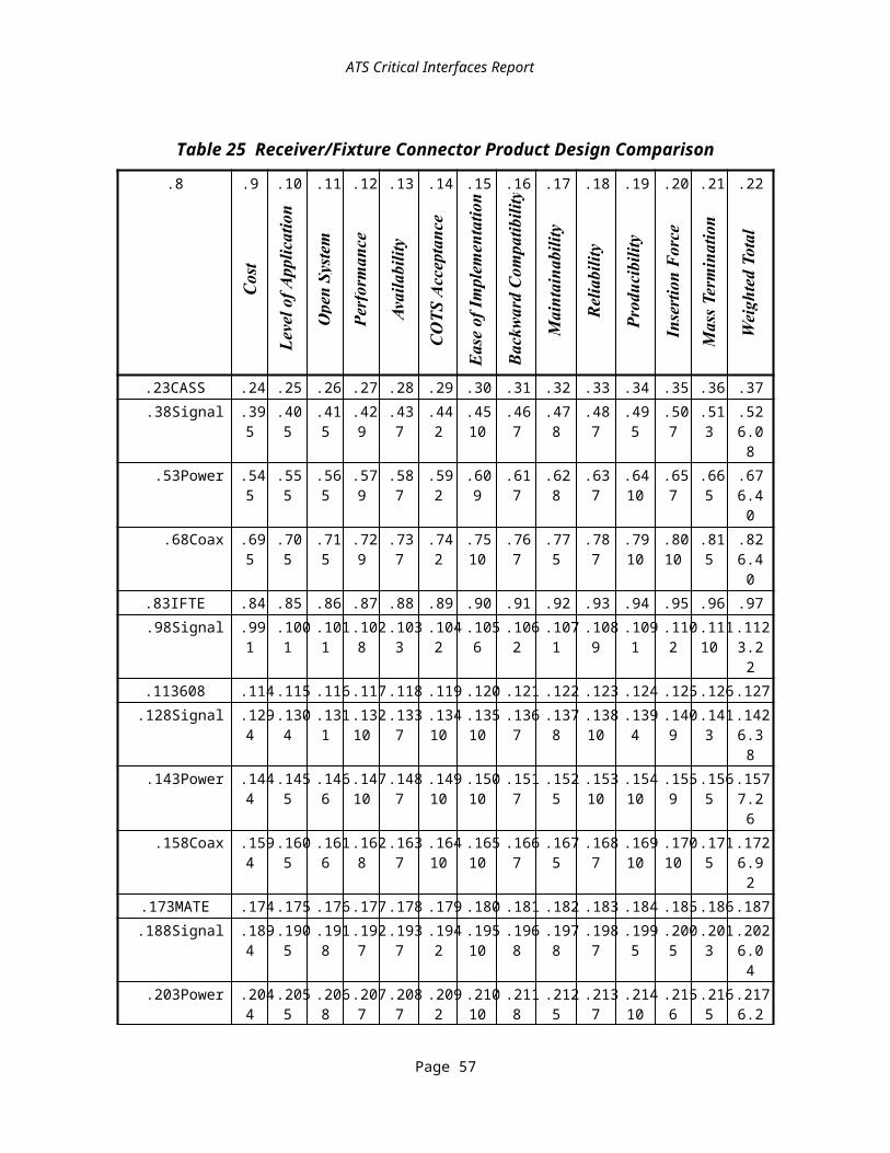
Note that the VPP-3 Instrument Driver specification requires that drivers communicate with the instruments through VPP-4 compatible drivers.
5.2.2.3.1.2IEEE P1226.5IEEE P1226.5, software interface to communication buses for ABBET, is derived from the VISA specification. The IEEE standards group (SCC20) is working closely with the VXIplug&play Systems Alliance to maintain compatibility between P1226.5 and VISA. The primary extensions included in P1226.5 are expected to support additional bus types.
5.2.2.3.2Instrument Communication Manager Recommendations and RationaleThe group concluded the candidate solution for the ICM interface is the VPP-4 (VISA) specification. There is strong acceptance throughout the industry for the VISA technology. Implementation and interoperability testing has been ongoing, and many companies have released products. The specification has an implementation history preserving upward compatibility and an organization to host further development.
5.2.2.4Instrument Driver APIThe DRV is the interface between the generic instrument classes serving the test procedure and the instrument driver. The calls made available at this interface include calls oriented to software housekeeping, such as initializing the driver itself, along with calls that cause the instrument to perform a function, such as arm and measure commands.The DRV interface is a potential CI for a variety of reasons. The service requests crossing this interface are communications between generic ATE assets (e.g., DMM) and specific ATE assets (e.g., HP model xxx DMM). The instruments are ATE assets, but the calls to the driver are either direct or close-to-direct consequences of action requests in the Test Procedure which is a TPS asset.Some instrument functions are available from a variety of instruments. However, the driver calls to access these functions vary from instrument to instrument. This interferes with TPS portability.Historically, cross-platform incompatibilities in the way drivers for the same instrument implement the same function have been a recurring ATE integration problem. In common commercial practice, the driver is acquired with the instrument from the instrument’s Original Equipment Manufacturer (OEM). This API is an interface where software developed by different organizations must work together. For these reasons, the DRV is a potential CI.
5.2.2.4.1Instrument Driver API CandidatesA variety of technologies address standardization of this interface.
· VXIplug&play (VPP) specification VPP-3 addresses this interface specifically.· IEEE P1226.4 also addresses this interface.· The ATLAS Intermediate Language (AIL) such as defined within the MATE
program gives definition to the functional content of instrument commands that is not covered by either of the above two documents.
Page 7

· The Test Resources Information Model (TRIM, IEEE P1226.11), addresses the functional specification of test equipment.
· Various forms of Instrument Command Languages such as the MATE Control Interface Intermediate Language (CIIL) format and the Standard Commands for Programmable Instruments (SCPI) language developed by industry groups also provide an approach to defining instrument command content.
· Hybrids combining elements of the above technologies.The following paragraphs summarize salient characteristics of these candidates.
5.2.2.4.1.1VPP-3VPP-3 is the VXIplug&play Systems Alliance specification for this interface. It is a defacto standard that defines a variety of calls from instrument drivers. There is broad industry support in the form of vendors developing compatible drivers.VXIplug&play instrument drivers are conceptually one layer above the traditional command set instrument programming methodology of the past. Rather than not delivering software with an instrument and requiring a user to include individual I/O statements throughout their application program, a VXIplug&play instrument driver includes all the communication details of a particular instrument in high-level software functions that are directly usable by end users as part of their application programs. The VXIplug&play instrument driver architecture accommodates traditional message-based instruments, both SCPI and non-SCPI, as well as direct control of register-based modules.VXIplug&play instrument drivers provide comprehensive access to the test and measurement capabilities of instruments. To develop a standard for multi-vendor instrument drivers, it is important to identify the fundamental requirements. The first fundamental requirement is that instrument drivers should provide turn-key, ready-to-go software modules that the user can employ directly in his or her own application program. Other areas of interest include the scope of functionality of the instrument driver, modularity and hierarchy, consistency in design and implementation, source code distribution, error handling, help information, documentation, revision control, distribution media, and installation. Figure 36 depicts a functional representation of a VXIplug&play instrument driver.
Page 8

Functional Body
COMPONENT FUNCTIONS
INITIALIZEFunction
CONFIGUREFunctions
ACTION / STATUSFunctions
INTERACTIVEDEVELOPER INTERFACE
PROGRAMMATICDEVELOPER INTERFACE
USER PROGRAM
APPLICATION FUNCTIONS
SUBROUTINE INTERFACE
DATAFunctions
VTL or VISA I/O Interface
UTILITYFunctions
CLOSEFunction
VPP Functional Diagram
vpp Figure 35 Figure 36 VXIplug&play Instrument Driver Diagram
One of the benefits of software is flexibility in presenting an instrument’s functionality to a user. With software, a single hardware instrument can have multiple panels and function calls targeted for particular applications. For these reasons, the VPP-3 specification does not define the specific requirements for each type of generic instrument, such as a multimeter, digitizer, spectrum analyzer, and so on. Rather, the specification defines consistent standards for architecture and packaging so that users get the unique benefits of individual instruments, yet in a consistent manner that promotes ease of use and is inter-operational between vendors.VXIplug&play instrument drivers have a well-defined modular design that is hierarchical in nature. If a user wants a simple, single-function interface to an instrument, such an interface is provided by application functions. If, however, the user wants more flexibility and access to more of the instrument’s functionality, the lower-level subsystem components of the driver are also available as modular pieces that can be used individually.
5.2.2.4.1.2IEEE P1226.4A draft IEEE P1226.4 has recently been balloted within the IEEE. This IEEE document is derived from the VPP-3 document discussed in Section 5.2.2.4.1.1.
5.2.2.4.1.3ATLAS Intermediate LanguageOne of the test programming languages used by the DoD is Abbreviated Test Language for All Systems (ATLAS). In a typical ATLAS system, the source code is compiled into an intermediate form called AIL and the latter is interpreted as the test is executed. During resource allocation, whether this is performed statically along with the AIL generation or at run time on a dynamic basis, test requirements are matched to available station assets.
Page 9

In either case, at run time, the test executive (AIL interpreter) concatenates the functional command information in the intermediate language representation with allocation-dependent addressing information for the specific allocated ATE asset. The AIL contains pre-allocation information semantically equivalent to the signal-oriented verb clauses of the ATLAS source, independent of the bus particulars.
5.2.2.4.1.4Test Resource Information ModelA Broad Based Environment for Test (ABBET) documents include the specification of what an ATE system should know about the presence and capabilities of the test resources in the ATE, including switching and instrumentation. The TRIM is presently being worked within the ABBET subcommittee of SCC20 as IEEE project 1226.11. The model is stated as an EXPRESS Information Model. It includes EXPRESS text representation as well as EXPRESS-G graphical representation (see ISO 10303-11).
5.2.2.4.1.5Instrument Command LanguagesThese technologies are described under interface ICL in Section 5.2.2.2. They provide an existing structure for stating what an instrument is to do.
5.2.2.4.1.6Driver API plus Instrument Command Languages HybridsAlthough SCPI was designed as a bus instrument command language, drivers for SCPI-implementing instruments are likely to make available signal-oriented services as calls that pass a SCPI string as an input parameter to the instrument driver. Standardizing this practice would not require the instruments themselves to be SCPI-driven, as this string could be interpreted and the information reformatted in the driver for non-SCPI instruments. While this approach does not have broad industry support, it can be achieved in the short term, even for non-SCPI instruments.
5.2.2.4.2Instrument Driver API Recommendations and RationaleThe CIWG recommends that instrument communication be handled by drivers conforming to the VPP-3 specification.The VPP-3 specification for this interface has been released and is being supported by commercial products. The IEEE specification (P1226.4) is not regarded as available technology at this time.Initially the group considered trying to meet the requirements for Generic Instrument Classes with a re-engineered DRV interface hybridizing VPP-3 and SCPI. Following review of this proposal with industry, it was decided to address the GIC as a separate layer (refer to Section 5.2.2.1). The VPP-3 specification is in use with commercial drivers shipping that meet this specification. It is believed that meeting GIC requirements at the DRV interface would force changes to the VPP-3 specification that are not upward compatible. To protect the upward compatibility of the VPP-3 specification the GIC has been designated as a separate interface. The group also concluded that the ADE must communicate with instruments through VPP-3 compatible instrument drivers and that the instrument drivers must be compatible with one of the frameworks supported by the FRM interface.
Page 10

5.2.3Software and Software Coordination InterfacesIn this section a variety of interfaces that organize the test procedure and related software running on the host computer are discussed.
5.2.3.1Diagnostic ProcessingThis is the interface from the Test Procedure or run time services supporting the TPS to an associated diagnostic reasoner, diagnostic controller, or other diagnostic process. Diagnostic tools are most frequently encountered in one of three forms: expert systems, decision-tree systems and model-based reasoners. Examples of such diagnostic tools that might be interfaced to the test procedure include the Diagnostic Reasoner from Hewlett-Packard and the Diagnostician from Giordano Associates. Other diagnostic tools are expert systems known as Fault Isolation System (FIS) and Expert Missile Maintenance Advisor (EMMA); decision-tree systems including Weapon System Testability Analyzer (WSTA), System Testability And Maintenance Program (STAMP), STAT and AUTOTEST; and model-based reasoners including I-CAT, POINTER, AI-TEST and ADS.Standardization in this area would allow tools to be written that could translate test strategy information to various test programming languages. Additionally, the tools would be interchangeable since one could use any tool to obtain the same output source code.
5.2.3.1.1Diagnostic Processing CandidatesThe Artificial Intelligence Exchange and Services Tie to All Test Environments (AI-ESTATE) committee within IEEE SCC20 is developing a framework of standards, P1232.x, which would be relevant to this interface.
5.2.3.1.2Diagnostic Processing Recommendations and RationaleThe present recommendation is to hold this interface as critical for the long term, but not to impose any requirements on this interface in the short term.The low incidence of auxiliary diagnostic processing in current DoD TPSs was regarded as reducing the potential re-host savings for the immediate future to a small amount.
5.2.3.2FrameworkFrameworks provide a common interface for developers of software modules, ensuring that they are portable to other computers that conform to the specified framework. By defining frameworks, suppliers can focus on developing programming tools and instrument drivers that can be used with any ADE that is compliant with the framework.The DRV interface, the ICM interface, and the instrument interface work together to provide communications in ATS as shown in Figure 37. Each of these interfaces are dependent on the computer and OS for which they have been designed. To ensure that the interfaces are compatible and interoperable with each other, the hardware and software environment in which they are developed and executed must be defined.
Page 11

The framework's specification accommodates this requirement by defining the hardware and software environment for developing and executing software modules. Examples of software modules are OSs, ADEs, instrument drivers, and I/O bus driver libraries.A VXIplug&play system framework is a well-defined set of components. This set contains all the software components that are necessary to build a complete test system. The framework definition contains rules, recommendations, and permissions, all of which define the required compatibility and interoperability of each component in the set.
Instrument Driver Interface
Communication Interface
Instrument Interface
Components of a Framework
sys_comm Figure 36
Operating System
Host Computer
ApplicationDevelopmentEnvironment
InstrumentDrivers
CommunicationManagement
VXI OtherIEEE488 &MMS
Figure 37 System Communication Interfaces
Specifically, each framework contains, but is not limited to, the following components:· Compatible ADEs· Instrument Drivers· Operating System· Required Documentation and Installation Support· Requirements for the Control Computer Hardware· Soft Front Panel· VISA Interface and I/O Software· VXI Instruments, VXI slot0, System Controller, VXI Mainframe
A system designed using a VXIplug&play system framework ensures that the ADE, DRV, GIC, ICM, and other FRM components are compatible and interoperable with each other.
Page 12
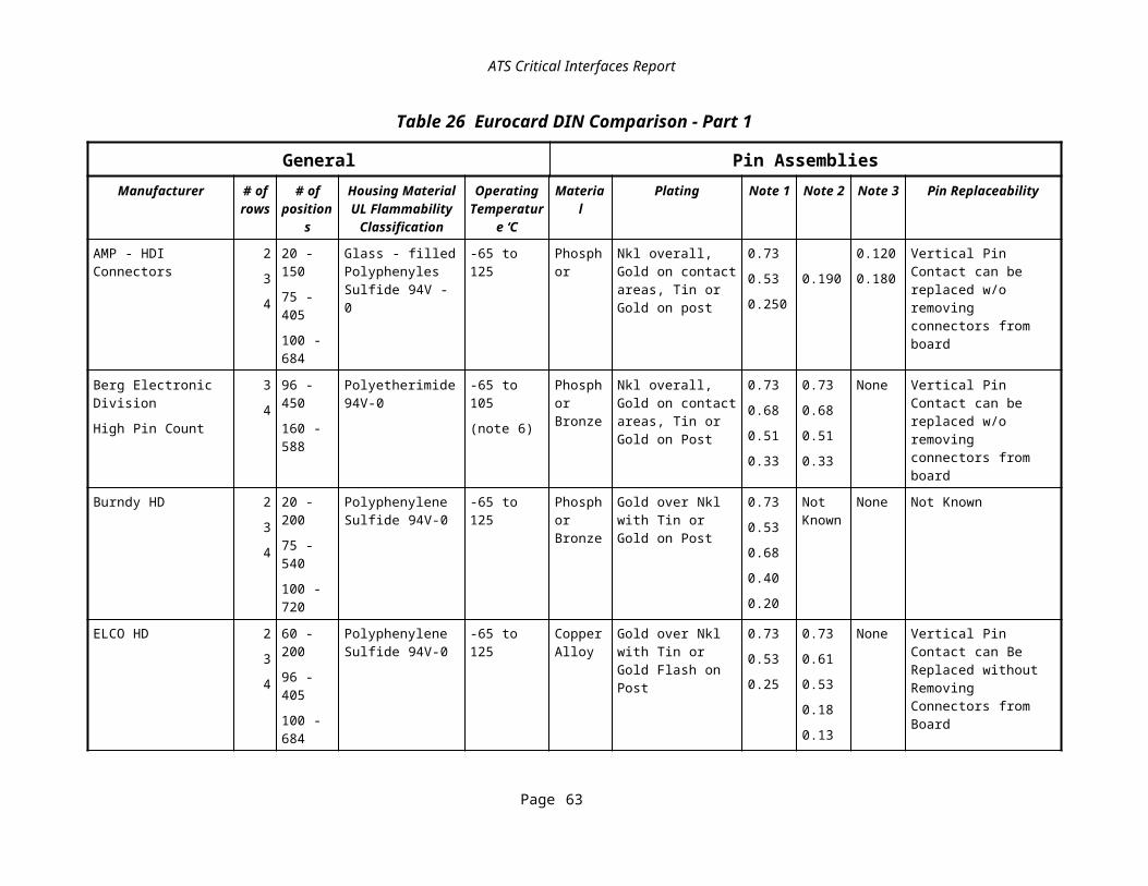
Following the framework requirements also ensures that all necessary system components have been included, resulting in a complete and operational system.Frameworks increase the likelihood that ADEs will be available on multiple platforms. National Instruments’ LabVIEW and LabWindows, and Hewlett-Packard’s HP VEE are supported on multiple platforms and are examples of this tendency. This greatly enhances one’s ability to move test software between platforms. While this does not ensure total portability of TPSs, it does eliminate the need to translate or rewrite the source code when it is ported. TPSs written in ANSI C, HP VEE, LabVIEW, LabWindows, or other VPP-2 compliant languages, can be read, edited, and executed on multiple platforms without making changes to the source code. This offers tremendous benefits to TPS re-host efforts. At the time this report was published, TYX Corporation was actively developing an ATLAS software package that is compliant with the WINNT framework. This is a tremendous breakthrough, as it marks the first time that an ATLAS software package will be able to communicate with the same instrument drivers as competing software packages.Frameworks also lower the cost to port a TPS because of the standardized manner in which subroutines are written. For example, the VXIplug&play WIN framework specifies how subroutines are called and formatted, ensuring that any application development environment that is WIN compatible can call the same Dynamic Link Library.Frameworks define the foundation upon which vendors supply ADEs, instrument drivers, and I/O bus software. Market pressures require instrument manufacturers to supply instrument drivers and I/O bus software for the most popular environments. This makes it less expensive and easier to develop a TPS. One reason is that instrument drivers are provided at no cost in many cases. More importantly, all the system software components are designed to be interoperable and compatible with each other. The VXIplug&play Systems Alliance conducts interoperability workshops to help vendors identify and eliminate problems.
5.2.3.2.1Framework CandidatesThe framework specification of the VXIplug&play Systems Alliance, VPP-2, has been developed specifically to address cross-platform standardization issues in the test domain, and is significantly more appropriate than other possibilities such as the CAD Framework Initiative or POSIX interface profile.As of the publication date of this document, the VXIplug&play Systems Alliance has defined ten frameworks. They are WIN, WIN95, WINNT, HP-UX, SUN, GWIN, GWIN95, GWINNT, GHPUX, and GSUN. The WIN framework supports text-based programming under the Microsoft Windows 3.1 OS and the GWIN framework supports graphical programming under the Windows 3.1 OS. The list below provides examples of application development environments that are available for use with three of the frameworks. As stated in the previous section, TYX Corporation is currently working on an ADE that is compliant with the WINNT frameworkExamples of ADEs that are certified for use with the HP-UX framework include:
· HP cc/c89 revision A.10.10· HP cc revision A.03.68
Page 13
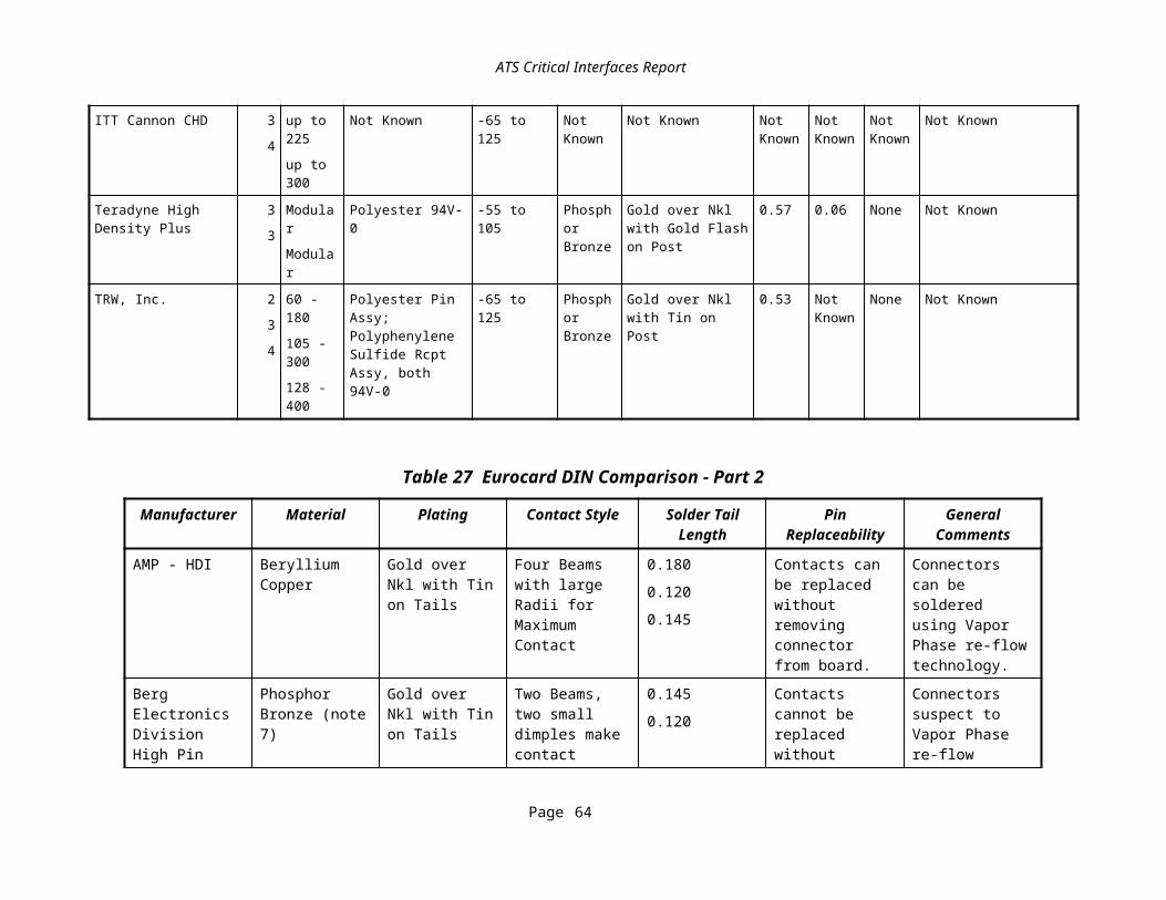
· HP VEE revision 3.1· National Instruments’ LabVIEW revision 3.1
Examples of ADEs that are certified for use with the WIN framework include:· Borland Turbo C/C++ revision 3.2· HP VEE for Windows revision 3.1· Microsoft Visual BASIC revision 3.0· Microsoft Visual C/C++ revision 1.0· National Instruments LabWindows/CVI revision 3.0· National Instruments LabVIEW Revision 3.1
Examples of ADEs that are certified for use with the SUN framework include:· HP VEE revision 3.1· National Instruments LabWindows/CVI revision 3.1· National Instruments LabVIEW revision 3.1· Sunsoft cc current revision· Sunsoft CC current revision
The cost of implementing VPP-2 is very low since it addresses the most popular OSs and application development environments available to the worldwide marketplace. The risk of implementing VPP-2 is very low since many companies supply ADEs and instrument drivers that are compatible with the specification. Some of the companies that provide VPP-2 compatible products are Microsoft, National Instruments, Hewlett-Packard, Tektronix, Wavetek, Racal Instruments, and GenRad. Given the widespread use of VPP-2, there is a tremendous amount of support available for compatible products, ensuring that implementation questions are rapidly answered.The Government’s cost to sustain VPP-2 is negligible since the standard is widely used in the commercial sector and is maintained by the VXIplug&play Systems Alliance. Additionally, the DoD can be assured of continual technological improvements because the VXIplug&play Systems Alliance has vowed to create new frameworks as hardware and software environments become popular. More importantly, one of the guiding principles of the VXIplug&play Systems Alliance is to make applications backwards compatible so users do not lose their investment in software.The primary risk associated with sustaining VPP-2 is whether the vendors who make up the VXIplug&play Systems Alliance will continue to support the frameworks. Some vendors may choose to support VPP-2 longer than others. However, when one compares the benefits of portability offered by VPP-2 to the status quo, this risk is well worth accepting.
5.2.3.2.2Framework Recommendations and RationaleThe CIWG recommends that to satisfy this CI, an ATS shall have a host computer with an OS and related infrastructure meeting the conditions of VXIplug&play System Alliance specification VPP-2. In addition, the ADE that is used must be compliant with one of the
Page 14

frameworks supported by VPP-2 as well as communicate with instruments through VPP-3 compliant instrument drivers.The cost and risk considerations reviewed above are favorable. The VPP-3 and VPP-4 technologies that are desired in the instrument communication stack depend, in their commercially available implementations, on the system characteristics laid out in this VPP framework document. Using commercial products for those layers will reduce the cost and risk of the total package, but requires a VPP-2 foundation.
5.2.3.3Multimedia FormatsTPSs include technical data and documentation. Test station maintenance requires extensive documentation. Presently, much of this information comes as text with some graphics and is usually delivered only on paper.To improve the usefulness of this information to test technicians and TPS maintainers, many TPS development and acquisition organizations are examining more extensive use of graphics and inclusion of video and audio clips. Applications include narrated video of test and repair operations (e.g., probing, component replacement) and hypertext linked test station, TPS, fixture, and UUT documentation. Providing this information on-line at the test station or at the TPS development station offers the potential to greatly increase test personnel productivity. The importance for re-host/transportability is that the data may be needed as part of the execution of the TPS. While this is not a big cost driver based on current DoD TPS purchases, it is likely to become more important in the future.Multimedia information has complex temporal relationships, multiple media data types, and dynamic and interactive behaviors. The interchange and communication of such information require specially designed multimedia data formats. Solutions in this area impact a wide variety of other areas including TPS acquisition, ATE data packages, UUT functional and parametric data, test station and TPS development frameworks, operator interface, application development environment, run time services, and data communication protocols.Commercial industry is very actively pursuing desktop and networked solutions in this area. Current desktop approaches tend to be framework dependent (e.g., Windows vs. Macintosh). However, delivery of multimedia over the World Wide Web (WWW) is stimulating considerable interest and investment. The formats used for the Web offer the potential for framework independence.The cost of implementation into test systems is heavily dependent on the framework selected. Commercial industry is making large investments in development for some frameworks such as Windows. Assuming such a framework is selected, the cost of implementation of the interface into the test system will be low.The cost of implementation into TPS and test system documentation will be high. Even using powerful authoring tools, multimedia on-line documentation of UUTs, fixtures, TPSs, test and repair operations, and test systems will be expensive to develop.The risk of implementation into common frameworks is being borne by commercial industry and therefore is low.
Page 15

The risk of implementation into TPSs and test systems is that the multimedia on-line documentation will be developed but will not significantly improve test personnel productivity. Based on studies of the advantages of on-line, paperless documentation this risk is low.The cost of sustaining a MMF interface should be fairly low. If widely supported frameworks and formats are selected, commercial industry will likely develop an abundance of tools to aid transport and conversion of multimedia information. Due to widespread commercial investment in this area, the sustainment risk should be fairly low.The availability of on-line, interactive, multimedia documentation of UUTs, fixtures, TPSs, test and repair operations, and test systems would be a great benefit during TPS porting and TPS development.
5.2.3.3.1Multimedia Formats CandidatesAlthough this area is rapidly changing, there are some candidates. The proprietary and/or framework dependent formats have the greatest immediate commercial support. The WWW formats are likely framework-independent formats for the near future. The standards-based formats are potentially more stable and vendor-neutral, but require a long time to develop and may never gain widespread commercial acceptance.
5.2.3.3.1.1Commercial and Proprietary FormatsThese have the widest immediate commercial tool support including translators to convert between formats. Many of the formats are dependent on the playback framework and, in some cases, are dependent on the delivery medium such as laser disk or CD-ROM (e.g., CD-I, CD-ROM XA, Kodak Photo CD). Most are proprietary and subject to rapid change as the vendors revise their products to meet market demands. Furthermore, the formats for storing information for authoring may be different from the delivery formats. Maintenance of the information requires acquisition of the authoring tools and data as well as the final data in delivery format. Candidate formats include:
· Audio: WAV (Microsoft audio file format)· Graphics: Vector formats (e.g., Microsoft’s PowerPoint, Corel), Bitmap formats
(e.g., PCX, BMP, TIFF), Page Formatting Languages (e.g., Adobe Postscript and Portable Document Format)
· Scripting: Macromedia Authorware, Microsoft’s Visual Basic· Text: Word Processor (e.g., WordPerfect, Microsoft’s Word), Page Formatting
Languages (e.g., Adobe Postscript and Portable Document Format)· Video: AVI (Microsoft video file format), Digital Video Interactive (DVI, Intel
compressed digital video format)
5.2.3.3.1.2World Wide Web FormatsWith the incredible growth of the WWW and the availability of web browsers for a wide variety of frameworks, the potential exists to use web authoring tools to develop multimedia applications. In fact, multimedia catalogs (e.g., clothing, cars) are already available on the Web. Some of the candidate formats include:
Page 16

· Animation: JavaScript (Sun proprietary language widely licensed)· Audio: WAV, Internet Phone/Internet Wave (proprietary to VocalTec),
Streamworks (proprietary to Xing Technologies)· Graphics: Graphics Interchange Format (GIF, CompuServe proprietary format)· Text: Hypertext Markup Language (HTML, open IETF application of ISO
SGML)· Three-dimensional scene models: VRML (Virtual Reality Modeling Language)· Video: AVI, Apple Quicktime, Streamworks (proprietary to Xing Technologies)
5.2.3.3.1.3Standards Based FormatsLong term, the WWW and proprietary or framework dependent formats may migrate into commercial specifications, national or international standards. As an example, the Interactive Multimedia Association (IMA) was formed to develop framework- and platform-independent recommended practices for multimedia framework services and data exchange formats. Some current candidate international standards in this area include:
· Audio: ISO/IEC 11172 Motion Picture Experts Group (MPEG-1, MPEG-2)· Graphics: ISO 8632 Computer Graphics Metafile (CGM)· Scripting: ISO Standard Multimedia Scripting Language (in development)· Text: ISO 8879 Standard Generalized Markup Language (SGML), ISO HyTime
(Hypermedia Time-based Structuring Language)· Video: ISO/IEC 11172 MPEG-1, MPEG-2
5.2.3.3.2Multimedia Formats Recommendations and RationaleThis interface is a potential long term CI for TPS re-host/transportability. No short term requirement has been placed against this interface because of the rapid growth driven by technology. If TPSs are developed that take advantage of the power of on-line, multimedia documentation, it is likely that the productivity of industry and Government test personnel would be greatly improved. At present, the large investment required to include this technology in TPSs and test systems is not being made. As a result, advances in this area and selection from among the candidates for this potential CI must await developments in commercial industry.
5.2.3.4Run Time ServicesThis interface is indicated by the mnemonic RTS on the run time interfaces diagram. This interface includes data logging services, operator I/O, timing and tasking control, and resource allocation performed at execution.This interface involves the means by which run time services are called during TPS execution. Although standards do not exist, various implementations do. Standardization in this area would allow the use of various test executives with any language that they support. Currently, a standard interface between TPS and Test Executive functions exist for ATLAS driven functions. However, the means by which various run time services are called vary depending upon the version of ATLAS implemented. Direct transportability
Page 17
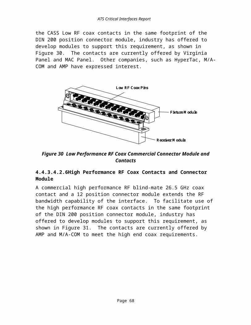
of a TPS across platforms will be compromised if the TPS requires run time services that are not supported on both systems, or if the implementation or calling methodology differs between host and target platforms.
5.2.3.4.1Run Time Services CandidatesThe following candidates were considered.
5.2.3.4.1.1ATLAS Intermediate LanguageTPS calls to run time services may be represented by the intermediate language to which ATLAS code is compiled. The implementations of TYX Programmer’s ATLAS Workbench System (PAWS), CASS ATLAS, IFTE ATLAS, MATE ATLAS, ARINC SMART ATLAS, and Boeing F-22 ATLAS all represent the intermediate language in different formats.
5.2.3.4.1.2ABBET Standards Related to Run Time ServicesP1226.10 is a recently started standardization effort to define run time services usable by a variety of TPS development scenarios. Services for resource allocation are being addressed in P1226.3.
5.2.3.4.2Run Time Services Recommendations and RationaleThe IEEE P1226.10 and P1226.3 Standards are under development and cannot be regarded as available technology. While there is a general pattern across ATLAS systems of reducing the language to an intermediate language for real-time processing, there is no agreement on the definition of the RTS interface or what functions are supported. This interface is considered critical, but no viable short term standardization strategy for this interface was identified. Therefore, it remains as a long term CI, but without any special requirements at this time.Various emerging technologies, such as middleware standards like Microsoft’s COM/OLE (Component Object Model/Object Linking and Embedding) and Object Management Group’s CORBA (Common Object Request Broker Architecture), are potentially relevant for the future of the development of distributed run time services.
5.2.3.5Test Program to Operating SystemThe TOS interface defines calls to host OS functions from the TPS. Some TPSs are highly dependent upon system calls unique to the initial TPS development system OS. A common use of calls to the OS in a TPS is in the area of file I/O. At the time of re-host, the OS calls may not be supported on the target ATE. OS calls are a chronic cause of non-portability in software.
5.2.3.5.1Test Program to Operating System CandidatesThe POSIX effort was considered as a candidate specification for this interface. Also considered was the role of an alternative framework definition (refer to Section 5.2.3.2). While there is an available POSIX-compliant add-on library for the Windows NT OS, POSIX compliance is not built into the frameworks that the test industry is supporting through the VXIplug&play efforts.
Page 18

Some framework standards, such as the GROW project in the GNU community, provide a framework-wide extension language.The simplest measure that will alleviate the transportability and re-hostability problems associated with OS calls is to ban them so as to ensure that the TPS is developed with an ADE which provides enough encapsulated run time services that direct calls to the OS are not required.
5.2.3.5.2Test Program to Operating System Recommendations and RationaleWhile generic extension mechanisms may be available in the future, for the short term it was deemed best to facilitate transportability by imposing the rule:
The TPS shall not make direct calls to any Operating System.OS calls are a persistent problem, and ADEs exist which obviate their use.
5.3Development InterfacesThis section examines the interfaces introduced in Figure 35.
5.3.1Application Development EnvironmentsAn ADE is a set of tools for developing applications, or the set of services provided to the programmer or test engineer by this collection of tools. In this report, the latter meaning has been employed -- the ADE is the set of services used by the test engineer as he/she creates or maintains a TPS. This section discusses the issues associated with the standardization of the ADE. There are three categories of these environments:
· Text-based· Graphical· Hybrid (text and graphics)
5.3.1.1Text-based Application Development EnvironmentsThese are environments where TPSs are written as a language composed of American Standard Code for Information Interchange (ASCII) text. Such languages for which standards exist include ATLAS, Ada, C, C++, and FORTRAN. In theory, any of these languages can be used to write TPSs (and most of them have been so used). ATLAS is the only language in this list that has been specifically designed for writing TPSs.
5.3.1.2Graphical Application Development EnvironmentsA graphical ADE is one in which two-dimensional constructs are used to define TPSs and other required entities. Examples of such are National Instruments’ LabVIEW and Hewlett-Packard’s HP VEE. These ADEs provide the ability to construct virtual instruments by selecting functional blocks from palette menus and connecting them with lines (wires) to pass data from one block to the next. Hierarchies of virtual instruments can be constructed. Programming structures such as for loops, while loops, and case statements for sequential, repetitive, and branching operations are also typically available.
Page 19

5.3.1.3Hybrid Application Development EnvironmentsThese combine text-based and graphical communication with the user. Icons and other diagrammatic structures are used for some parts of the program specification, while a textual language is used to specify other parts. A typical example would be the use of graphical techniques to specify the contents of a window while the text language specifies the operations to be performed when the user takes an action (such as pushing a button). The text language may or may not conform to a standard. There is no formal standard for the graphical elements. Microsoft’s Visual Basic is an example of a Hybrid ADE.
5.3.1.4Desirable Characteristics in an Application Development EnvironmentsThis section contains a list of suggestions or an initial set of requirements to be met by an ADE.
· Development - The ADE should include tools to aid the development of a TPS. If the ADE supports the development of a TPS on platforms other than the target platform, it is useful if a target platform simulator is available.
· Requirements - The ADE should support the development of test requirements documents and any other related requirements documentation. The documents produced should be in a readily accessible machine-readable form. Such a form includes ASCII text or that of commonly accessible word processing software.
· Strategy and Design - The ADE should support the development of test strategy, test flow, and other related design documentation. The documents produced should be in a readily accessible machine-readable form. Such a form includes ASCII text or that of commonly accessible word processing software.
· Version Control - The ADE should provide (or be compatible with the use of) version control software to allow the controlled production and release of initial versions and updates of the TPS and related documents.
· Multi-platform Availability - Languages or ADEs available or portable across many computing environments are preferable.
· Modules and Libraries - The ADE should support development of libraries of reusable modules. A method of self-documentation of these modules should be provided that links descriptions of all module interfaces and functions to the module itself. A programmer should require no further documentation to successfully reuse the modules in another application.
An ADE that supports the development and use of the full range of TPS documentation can vastly simplify the porting of a TPS. It will reduce the need to reverse engineer the TPS to obtain the information necessary for the re-host operation.An ADE that supports and/or automates the full range of TPS development activities can provide an environment for the orderly, disciplined, and efficient development of requirements, strategies and designs, and products. This leads to predictable (and reduced) cost and improved schedule performance.
Page 20

5.3.1.5Application Development Environments CandidatesIn the text-based category, a variety of languages are used for the development of test software. This includes FORTRAN, BASIC, C, C++, Ada, and ATLAS. There are public standards for all of these languages. Graphical “languages” on the other hand are not standardized but are proprietary and peculiar to a particular ADE product. Examples include Microsoft’s Visual Basic and National Instruments’ LabVIEW. Some ADEs combine proprietary GUI features and a standard language. Examples of this include TYX PAWS, National Instruments’ Lab Windows/CVI, and Hewlett-Packard’s HP VEE.
5.3.1.6Application Development Environments Recommendations and RationaleThe working group decided that this interface is not critical. This decision was reached after balancing a variety of considerations. Significant factors in this decision include the following.
· There are two approaches for standardizing in this area: one is to standardize on the ADE and the other is to standardize on the DRV, FRM, GIC, and ICM interfaces. The commercial marketplace is moving to standardize on the DRV, FRM, and ICM interfaces instead of ADEs. A few examples include TYX ATLAS, Hewlett Packard’s HP VEE, National Instruments’ LabVIEW, and Microsoft’s Visual Basic. This factor favors excluding the ADE from the CI set.
· The adoption of the DRV, FRM, GIC, and ICM interfaces allows one to use a variety of compatible ADEs on a single ATE. This simplifies the task of moving a TPS to another test system within the same framework because the ADE can be installed on the target system. This reduces the potential payoff of standardizing on a particular ADE. Some ADEs are multi-framework compatible, allowing a TPS to be moved to an ATE using a different framework. This factor favors excluding the ADE from the CI set.
· There is appreciable re-host cost leverage in staying with the same ADE, beyond the savings afforded by having a VPP-2 compatible framework on source and destination ATEs. This factor favors including the ADE in the CI set.
· Commercial vendors are under strong competitive pressure to continuously introduce improvements in this interface. Since standardization in this area shows no signs of being embraced by the commercial marketplace, the DoD would not be able to take advantage of the improvements in commercial products that choose not to support the standard. This factor favors excluding the ADE from the CI set.
On balance, the factors favoring excluding the ADE from the CI set were felt to outweigh the factors favoring the inclusion of this interface. While the ADE is not recommended as a CI, it must communicate with instruments through VPP-3 compatible instrument drivers and it must adhere to all restrictions placed on it by the FRM interface.
Page 21
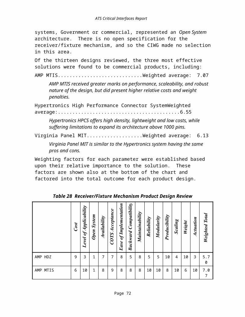
5.3.2Digital Test Data FormatsDTF describes the sequence of logic-1's and logic-0's necessary to test a digital UUT. Digital test data is generally divided into three parts: patterns, timing, and levels. In addition, there may exist certain diagnostic data that is closely associated with the digital test data.
5.3.2.1Logic ValuesThe logic values normally used in test are logic-1, logic-0, and between (neither logic-1 nor logic-0). Each logic value must also have a direction associated with it, where the direction is either stimulus or response (or both). A stimulus logic value is applied to the UUT and a response value is sensed from the UUT.
5.3.2.2PatternsThe patterns contain the logic values that are used to test the UUT. The pattern is generally represented as a two-dimensional table of logic values, where each column of the table represents activity on some pin or test point of a UUT and each row represents the activity at a certain time (increasing rows correspond to increasing time).
5.3.2.3RelevancyEach logic value must be annotated with a relevancy flag. If the flag is "care", then the logic value must appear exactly as specified in the TPS. If the flag is "don't care", then the logic value is just a place holder and imposes no requirements on the TPS. Relevancy information is most often associated with response information ("masked" outputs) but can be usefully applied to stimulus information as well.
5.3.2.4TimingThe pattern supplies a list of logic values to be driven to or sensed from the UUT. The timing information states when the TPS should drive and sense. To be precise, the digital test data must explicitly state the time that every edge should occur.Some digital test sets omit certain timing information, assuming that the tester will provide it. A common example is to omit sense timing, expecting that the tester will sense at the end of the period. Basing a TPS on assumed data is poor engineering and is not recommended.The other aspect of digital test timing is that it may be either "high fidelity" or it may be filtered. High fidelity tests record the timing as it appears at the interface to the UUT. Filtered tests record the timing as it might be programmed in a tester, after guard-banding and accounting for ITA delays. It is impossible to recover high fidelity timing from filtered tests, although it is simple to convert in the other direction.Timing complexity is the single biggest hurdle in implementing a digital test set on a tester. Normally, an individual edge can occur anywhere within a range of times. This is represented as a tolerance on the edge timing, for example, 10 ns +2 ns. The presence of correct timing tolerances makes accurate translation to a new tester far simpler.
Page 22
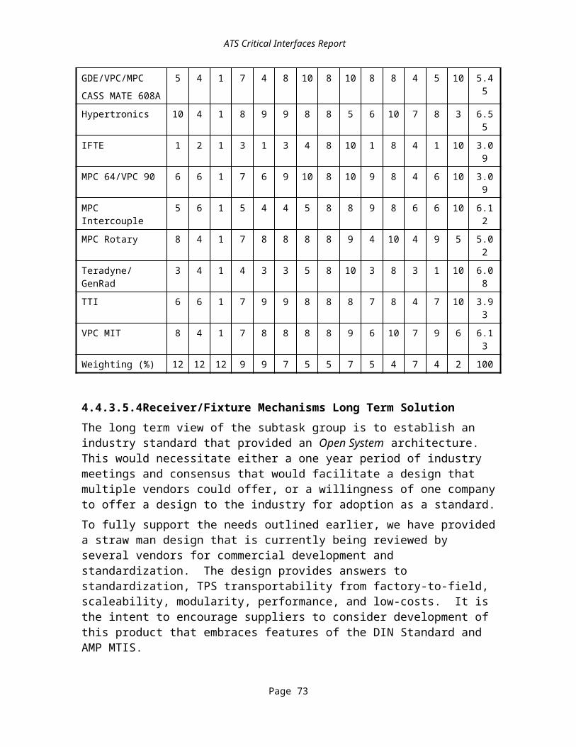
Patterns sometimes include format information, which allows the pattern to represent common sequences of logic values with a single character code.
5.3.2.5LevelsThe final aspect of digital test data is the electrical values assigned to the various logic values. These are the voltage levels and current levels that are assigned to logic-1 and logic-0. These levels may be different for different pins on the UUT. Levels include, for the purposes of this interface, the proper load conditions for each pin, such as capacitive load or input impedance.Levels are often derived by a test engineer from the logic threshold specifications for the UUT. However, it is better practice if the TPS states the levels explicitly. Like timing, levels can be high fidelity or can be filtered. Only high fidelity levels should be recorded as the transportable test data. Levels should also be stated with tolerances, to quantify allowable errors in the tester pin electronics.
5.3.2.6CompressionThe patterns for certain classes of UUT can be highly compressed. This is desirable since the raw patterns are often quite large and can require more digital storage than any other component of the TPS. Examples of compression are:
· Scan tests are characterized by long sequences of activity on a few pins with all other pins being held steady. 1149.1 (boundary scan) tests are a special type of scan
· Self tests are characterized by extremely long sequences of no activity except for a clock. The self test starts with a short initialization sequence and ends with a readout of the test result. Scan is often used for the initialization and readout portions of the test
· Memory tests are characterized by simple counting algorithms to generate the tests. The size of a memory test description is generally independent of the size of the memory. A memory test can often be described in just a few lines of code. The corresponding parallel vectors can number in the hundreds of millions
· Signature analysis tests are characterized by algorithmically generated input test vectors and a compression algorithm that compacts the output vectors into a single, short (usually less than 1K bits) word
Compression in the patterns is acceptable provided the compression algorithm is well specified. In the case of boundary scan, for instance, the Boundary Scan Description Language (BSDL) description of the UUT may suffice.
5.3.2.7DiagnosticsJust as digital tests have special formats for specifying stimulus and response, so they have special formats for diagnostics. There are two main diagnostic techniques, for digital UUTs, that have special formats.
Page 23

· Fault dictionaries are lookup tables that relate failures on the outputs to replaceable/repairable units in the UUT. A fault dictionary is associated with a particular vector set.
· Backtracing attempts to locate the first failed component by following failure indications from the UUT outputs where they are first detected back toward the UUT inputs. Backtracing requires a vector set that includes response data for nodes internal to the UUT. Full fidelity timing for these internal nodes is quite often ignored in backtrace vector sets, but is absolutely critical to transportability.
Executing a backtrace diagnostic generally requires information on the physical layout of the UUT for probe placement. For automatic probing this must take the form of actual X,Y coordinates. For manual probing this takes the form of a picture that can be presented to an operator. Finally, backtracing almost always takes advantage of "dependency models", which are models of the components on the UUT. These models record which outputs of the component are affected by which inputs. The models are used to optimize the backtrace diagnostic by limiting the probing choices. Backtracing is often built in to a test system, and the dependency models are often tester-specific.
5.3.2.8ModelsSimulation models are often requested as part of the digital test data. However, simulation models are not needed for TPS transportability. In a transportability scenario, simulation models would only be used to regenerate expected data for a given set of stimuli. The regenerated data, will be a full fidelity vector set. Had the full fidelity vectors been provided in the first place, the simulation models would not be needed.Models are sometimes used to create a new TPS through ATPG. This is incompatible with the transportability scenario, however, since it is based on the premise that the original test data was inaccurate or incomplete. If the original test data were accurate and complete then there would be no value in regenerating tests through ATPG. In fact, the regenerated test may well be of lower quality than the original test, since not all of the assumptions made during the original TPS development are usually known during TPS porting.Simulation models are very valuable for TPS maintenance. Models are required to determine the correct expected data when the test (stimuli) changes or there are changes in the components used in the UUT.
5.3.2.9Digital Test Data Format CandidatesThere are a number of candidates for transmitting digital test information. Commercial formats that are defacto standards include the SEF and WGL from Summit and LSRTAP (SDF) from Teradyne. Formal standards include IEEE Std 1029.1 Waveform And Vector Exchange Specification (WAVES). Simulator output files are often used to transfer digital patterns; these generally exhibit high fidelity timing, but omit direction and relevance information, and are therefore unacceptable.
Page 24

5.3.2.9.1Commercial Formats
5.3.2.9.1.1Standard Event FormatThis is a widely used proprietary format owned by Summit Design, Inc. It provides patterns with logic-values, direction, and relevance and allows full-fidelity timing. It does not include levels or timing tolerances.
5.3.2.9.1.2Waveform Generation LanguageThis is a widely used proprietary format owned by Summit Design, Inc. It is more compact than SEF and provides a higher-level view of the behavior of the test vectors. It does not include levels or timing tolerances.
5.3.2.9.1.3LSRTAP (SDF)This is another widely used format, created by Teradyne. It communicates all of the pattern, timing, levels and diagnostics for a vector set, except that it does not provide timing tolerances. Because it is an open data format, many post-processors exist to translate the digital data into whatever format is required by the target tester. The LSRTAP format has been recently placed into the Navy specification, NAWCADLKE-MISC-05-PD-003 entitled Navy Standard Digital Simulation Data Format (SDF).
5.3.2.9.2Standards-based Formats
5.3.2.9.2.1IEEE Std 1029.1-1989IEEE Std 1029.1-1989 provides all of the pattern, timing and compression capabilities to express a vector set. It does not provide information on levels. It is designed to get levels from IEEE P1029.3 Test Requirements Specification Language (TRSL) and to get fault dictionary information from IEEE P1029.2 Fault Detection and Localization (FDL), two standards under development.
5.3.2.9.2.2IEEE P1445 Digital Test Interchange FormatThere is a project within the IEEE to define the DTIF standard. That effort has been assigned project number 1445. The requirements document for this project calls for all the capabilities of LSRTAP (SDF).
5.3.2.9.2.3IEEE P1450 Standard Test Interchange LanguageA proposed IEEE standard that appears to provide approximately the same functionality as SEF or WGL. It is focusing on “the giga-bit problem” of testing large Integrated Circuits, such as microprocessors. Optimizing pattern compression is an important objective of STIL.
5.3.2.10Digital Test Data Format Recommendations and RationaleThis interface is intended to be used for capturing the output of digital automatic test pattern generators. The recommended requirement for this interface is that LSRTAP (SDF) be used as the format for patterns, timing, and levels, and that the digital test data should use high fidelity timing and levels. The timing is especially important.
Page 25

Test which can be effectively expressed in the native language of the ADE used to develop the main test procedure need not use LSRTAP (SDF) format. This format is for the use of test implementers who, because of the size of their digital test data sets, wish to transport them separately from the native language of the ADE.LSRTAP (SDF) is selected over other alternative formats because it is widely used in industry and it is already part of the DoD TPS development process. Therefore, LSRTAP (SDF) has the lowest short term insertion cost and the lowest short term risk.The short term cost of implementation is very low, since the selected candidate is already in use within the CASS and IFTE DoD ATS families.The risk of implementation is very low since the candidate has experienced widespread use in industry and within the DoD. The cost of sustainment is relatively low, since the candidate is supported by a variety of commercial and DoD tools. Because of its use within industry, it is expected that the DoD investment to maintain this interface will be minimal. Current industry acceptance and experience with this candidate reduces the risk of sustainment.The principal effort in porting a digital TPS is focused around the timing. The support of full-fidelity timing by LSRTAP (SDF) could reduce TPS porting time by an order of magnitude.
5.3.3ATE and UUT Information InterfacesThis section addresses four information-related interfaces included in Figure 35. Information interfaces are critical to allocation and personalization of the TPS to the ATE.
· Adapter Function and Parametric Data address active circuits on the fixture and electrical characteristics
· Instrument Function and Parametric Data characterize the capabilities of the instruments
· Switching Function and Parametric Data describe the possible states of the switching, how to command the switch to obtain these states, and the electrical characteristics of the paths connected
· UUT Test Requirements describe what is required to test the UUT. These must be distinguished from the capabilities available on a particular ATE in order to facilitate the use of the TPS with a variety of ATEs
Definitions, candidate solutions, and decisions regarding these four interfaces are discussed in the following paragraphs.
5.3.3.1Adapter Function and Parametric DataThis information is similar to the IFP and SFP interfaces, but it addresses the electrical behavior of the fixture which connects the UUT to the ATE. Function description is included to allow for the case of active fixtures. Describing the function of the fixture begins with a statement of the wirelist association between receiver terminals and UUT terminals. Performance parameters are required to complete the characterization of the path between the instrument and the UUT, so as to be able to construct a model of the
Page 26

effective instrument applied to the UUT signals (characterized with reference to the UUT interface).
5.3.3.2ATE Instrument Function and Parametric DataThis is the description of the capabilities of the ATE stimulus and measurement devices, how they are controlled, and how they are connected within the ATE. This information includes the following.
· Instrument Capabilities - This defines what the instrument can measure, stimulate, and/or load the circuits to which it is attached. This includes identifying the function, such as measure volts, and quantitative performance characteristics including the range over which a voltage can be measured and the resolution and accuracy (as a function of choice of range) to be expected from the measured value.
· Instrument Control - The command vocabulary by which the instrument can be controlled to apply these behaviors.
· Instrument Limits - Limits are associated both with the safety of the instrument and surety of resolution performance. For example: “Do not expose this instrument to more than 1 KV across the sensing terminals” or “Accuracy of voltage stimulus guaranteed with the instrument sourcing up to 100 mA.”
5.3.3.3ATE Switching Function and Parametric DataThis interface refers to the description of the capabilities of the ATE switching devices, how they are controlled, and how they are interconnected with other ATE devices. This includes the possible states of the separately-settable switch elements, the connectivity through the switch in each such state, and electrical performance characteristics of the paths connected as a result of the switch state. For an extended example of this kind of information, see the section on switching under hardware interfaces on basic switching requirements for a DoD ATE. The receiver is shown as a separate block in the decomposition diagrams, but the contribution of fixed wiring and the connectors in the receiver are to be covered in this information for the purposes of satisfying this paragraph. The switching parametric information includes as-installed electrical path performance from the point to which the instrument characteristics are referenced out to the receiver/fixture disconnect surface.
5.3.3.4UUT Test RequirementsRe-hostability of TPSs requires isolating this information from the implemented capability that depends on the particular resources allocated on a specific ATE. This information takes the form of specification of loads, measurements and stimuli which must appear at the UUT interface in order to accomplish the required test. High re-host costs in the past have been associated with a failure to record and/or preserve the signal-oriented action capabilities as required as opposed to as used. This problem is most visible in the allocation phase of TPS development. When a TPS is ported or re-hosted, a fresh allocation is performed. The starting point for allocation must be available for this to be
Page 27

done economically. If only the allocated version of the test procedure is available, much effort is wasted reverse engineering the test requirements from the test procedure.
5.3.3.5Information Interface CandidatesThere are a variety of ways to meet the needs in this area, including documentation, ATLAS compiler databases, ATLAS language, CAD/CAM formats, the TRIM and/or VPP-5 expanded to include parametric data. The following sections expand on these alternatives.
5.3.3.5.1DocumentationThis refers to data items which are organized and presented for human interpretation without any special provisions for machine comprehension of the content as would be desired for fully automatic allocation processing.Several commercial products exist that create Test Requirement Documents (TRDs). TYX and LCTI, among others, offer tools for creation of TRDs. These are documents that address the UUT test requirements. In most cases, detailed Data Item Description (DID) information must be entered manually to create a TRD. Additional tools exist by which similar forms-mode input information is also used to automatically generate TPSs.It should be noted that the correctness of this information is essential. The most exhaustive form of instrument capability description in current practice is the product documentation provided by the instrument OEM and system integrator. Calibration records, where available, offer a measure of enhanced reliability.There are various forms of documentation; clickable hyperlinked electronic form, non-hyperlinked electronic form, Red Team Package (e.g., paper with a standardized content and organization), and paper in vendor-format.On-line electronic documentation may be regarded as an available technology in the short term because:
· For any new documentation, the documents are developed on-line using document tools with at least an HTML output filter.
· For existing paper documentation there are commercial records-management systems that would put scanned images of the documents on-line under some form of library management.
The biggest problem is that current documentation practices do not identify the information items adequately for automated processing (e.g., automatic allocation, station configuration).
5.3.3.5.2ATLAS Compiler (e.g., TYX, ARINC SMART) DatabasesTPS source code is compiled by ATLAS compilers using the syntax and semantics defined by the ATLAS language. Additionally, many compilers use databases in conjunction with the compiler.The schema for one of these databases can be considered available because each version is supported by a working implementation. On the other hand, selecting one of these
Page 28

incompatible implementations over the others has disadvantages as a convergence plan because of competition and openness issues.
5.3.3.5.3ATLAS LanguageThe ATLAS language was initially conceived as a medium for human/human communication of test requirements. Its adoption of formal syntax was for precision. The economic pressures to make it function as a high-order programming language for programming ATE has proven irresistible in most cases. The SMART system (which is used widely in commercial aviation) is the only major example where ATLAS is written strictly at the UUT-oriented level. In most other cases, escapes to lower levels of test description where the particulars of the ATE at hand get inextricably intertwined with the UUT requirements are commonly used, resulting in test procedures with little portability. However, as the format in which to capture UTRs, ATLAS is a competent medium of expression. It is a viable short term option for that area of portability enhancing information.
5.3.3.5.4CAD/CAM FormatsA variety of commercial and standard formats used in the design and manufacture of electronics contain portions of the kind of information addressed here. These include simulation model formats such as VHSIC Hardware Description Language (VHDL)-IEEE 1076 and Spice; design data formats such as Electronic Data Interchange Format (EDIF), and manufacturing interface formats such as the IPC D-350 family of formats and Standard for Exchange of Product data (STEP) (ISO 10303). The PDES Application Protocol - Electronics (PAP-E) program sponsored by the Air Force Manufacturing Technology (ManTech) Directorate has experimented with creating bundled folders of information using multiple currently used formats to create a sufficient representation for test purposes.For many active circuits, the most readily available form of functional description is in the form of simulation models. Simulation can be used to assess the expected success of test equipment configurations when the complexity of the test strategy exceeds what can be verified with a simple rule check. Ongoing programs, such as the Air Force ManTech Virtual Test Program, are pursuing environments in which simulation is used to check allocation decisions. The DANTES system from Cadence is an existing commercial example. This information representation is applicable to switch and instrument functions as well as to active elements on the fixture.This technology cannot be regarded as available now, although partial solutions such as asking for VHDL descriptions of logic circuits used in an active fixture, or standard format programming files for PROMs, would qualify as having high present-day availability.
5.3.3.5.5Test Resource Information ModelThe P1226.11 TRIM is an EXPRESS information model, developed in the context of the IEEE ABBET architecture, that identifies the information necessary to describe or characterize test components and systems. The TRIM identifies all the categories of information, the interrelationships between the categories of information, rules associated
Page 29
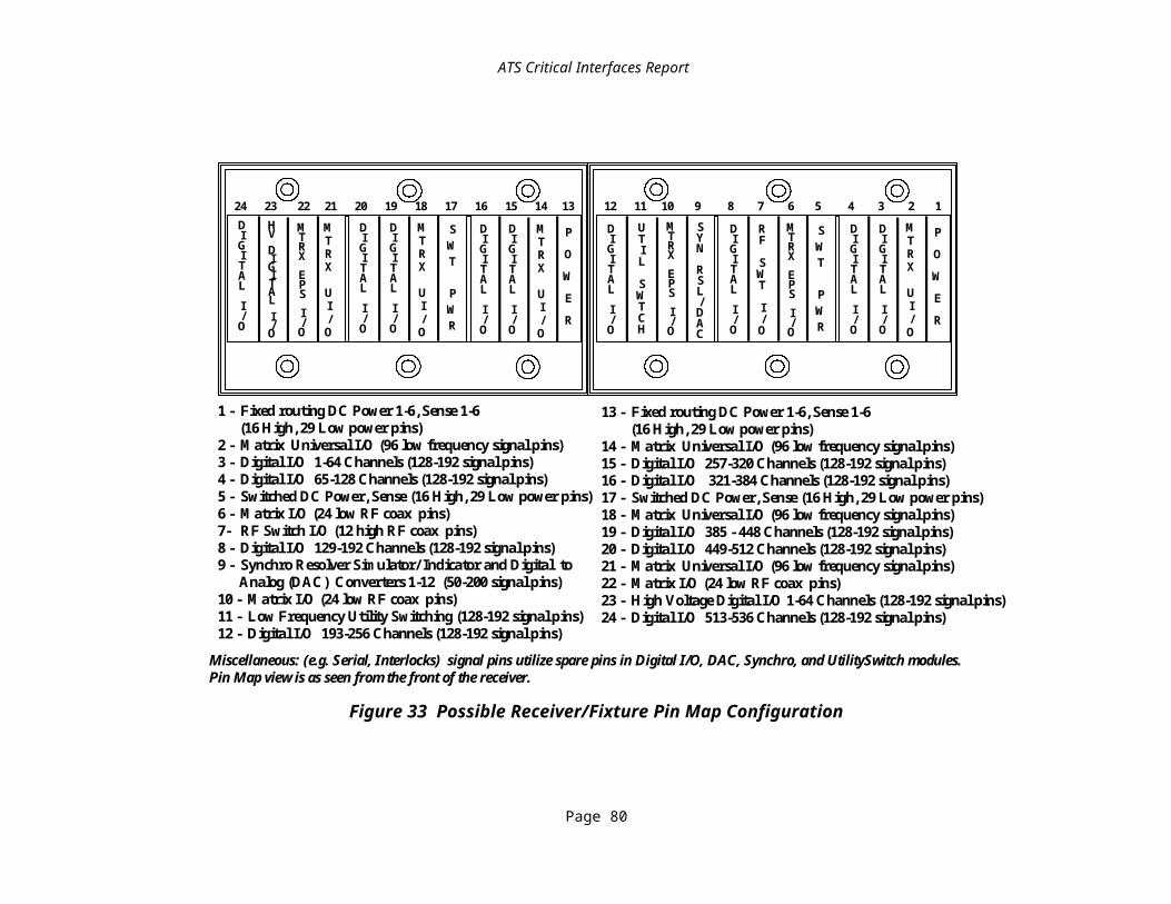
with the information, and the form of each category of information. Any particular test system will be described by an instantiation of this information model.
5.3.3.5.6VPP-5 Expanded to Include Parametric DataVPP-5 is the VXI Component Knowledge Base Specification. It is intended to ensure that VXIplug&play hardware components can be sufficiently described to allow software tools to be created to aid system design, system integration and system verification. A system design tool would allow the user to design a system prior to ordering components. A system integration tool would allow the user to take a new component and install it correctly. A system verification tool would allow the user to verify that an existing configuration is correct.VPP-5 could be a solution in the long term provided that it gives adequate parametric coverage of performance issues. This solution is not regarded as immediately available because the specification does not currently address parametric data.
5.3.3.6Information Interface Recommendations and RationaleThe CIWG found no adequate solutions for these information requirements that were capable of being implemented immediately. The CIWG recommends that the ARI pursue standardization of these interfaces in the future. For the short term, the recommendation is to be more thorough in the acquisition of TPS documentation.Both the P1226.11 and the VPP-5 specification are attempts to develop a standard to replace the vendor-peculiar schemas used in applications such as the ATLAS compiler databases cited above.
5.3.4TPS DocumentationThis category consists of the supporting documentation, provided by the TPS developer, whose purpose is to convey an understanding of the design philosophies incorporated into the various elements of the TPS hardware and software, along with detailed instructions for selected processes such as how to regenerate the executable program from the source libraries provided. These documents may include the Test Strategy Report (TSR), Diagnostic Flow Charts (DFC), Test Requirements Document (TRD), Test Diagrams, Test Program Instruction (TPI), and Automatic Test Program Generator (ATPG) Support Data. These data are bundled together in the Test Program Documentation (TPD) interface.
5.3.4.1TPS Documentation CandidatesThe following represent candidate specifications for TPS Documentation:
· DI-ATTS-80284A Test Program Set Document· DI-ATTS-80285 Engineering Support Data· DI-ATTS-80285A Engineering Support Data· MIL-STD-1345B Test Requirements Document· MIL-STD-1519 Test Requirements Document
Page 30

DI-ATTS-80284A establishes the criteria to ensure uniformity for the submittal of the Operational Test Program Set (OTPS) documentation. This documentation consists of the Operational Test Program Instruction (OTPI)/Test Program Instruction (TPI) and the Master Test Program Set Index cards (MTPSI). The documentation supports the delivery of the OTPS and is used in conjunction with appropriate ATE to test a UUT.The OTPI is the result of merging one or more TPIs into a group to support an OTPS. The TPI shall consist of information needed to support the TPS software; e.g., test set-up and probe point locations. The MTPSI is the OTPS element that contains a list of all TPS items required to test a UUT on a specific ATE system.DI-ATTS-80285A is the Engineering Support Data (ESD) that consists of a test strategy report, ATPG outputs, TPS source files, and information created during the development of TPSs.The TSR specifies that TPS design and performance characteristics as well as the rationale for the test method used for developing the TPS.The ATPG data consists of the data sets that are necessary and sufficient for post processing and merging the final results of an ATPG system execution into a test program that will be utilized on a designated ATE system. It also contains all the final command and data files that are necessary and sufficient to maintain and generate the final ATPG data. Examples of ATPG data contents are: model files, stimulus files, fault files, and ATE specific files. Examples of command and data files are: probe commands and utility commands.The TPS source data consists of data or text files generated during TPS development, including CAD files, databases, spreadsheets, and word processing files.MIL-STD-1519 establishes the requirements for the preparation and control of the Test Requirements Documents (TRD) used in specifying testing requirements for testing UUTs. The test requirement is supposed to be independent of any specific test apparatus.
5.3.4.2TPS Documentation Recommendations and RationaleIn all cases, a TPS shall contain a full set of source code for the test program. This includes embedded and downloaded elements. Other documentation shall be at the discretion of the acquiring program, but those documents acquired shall conform to the following documents, as applicable:
· DI-ATTS-80284A Test Program Set Document· DI-ATTS-80285A Engineering Support Data
In addition, it is recommended that future document be acquired in HTML 3.0 format. HTML 3.0 is the latest version of the HTML standard. HTML is an SGML based format that is the current standard used for WWW pages. HTML 3.0 documents can be read by document viewers on many computer hardware platforms and operating systems. The HTML 3.0 format is also an electronic format that can be communicated via the NET interface.DI-ATTS-80284A and DI-ATTS-80285A are currently enforced on both Navy and Air Force TPS acquisitions and should be considered as “standard” requirements. The Army’s
Page 31

requirement for a Component Fault Accountability Table (CFAT) is not addressed by either DI-ATTS-80284A or DI-ATTS-80285A. Paragraph 10.4.9.4 in DI-ATTS-80285 addresses the CFAT and should be enforced if the requirement for a CFAT exists. The documents referenced above can be “tailored” by each OTPS SOW based upon the particular requirements of each program.
Page 32

6Recommendations for Further ResearchThis section collects some questions and issues where the CIWG felt hampered by limitations in current technology or available information about the performance of that technology. Research into these issues will not only benefit DoD ATS effectiveness, it specifically will benefit the DoD management of ATSs by CIs.
6.1Hardware IssuesThe discussions and analysis of the hardware interfaces identified two areas needing additional research: parts of the RFX and the SWM architecture. The CIWG developed partial specifications for both of these areas. These specifications will undergo further development during the demonstration phase of the Critical Interfaces Project, but should also be a focus for further study and refinement by the ARI in concert with industry with a goal of future commercial standardization.
6.2Software IssuesResearch recommendations are presented here on an interface-by-interface basis. Eventually the research should be performed based on functional threads, such as the instrument communication stack, rather than on an interface-by-interface basis. Integration of these research questions into a structured plan is left to the CIWG demonstration planning subgroup and ARI Steering Committee, as appropriate.Table 31 summarizes the CIWG recommendations which are detailed in the paragraphs that follow.
Table 31 Critical Interfaces Standardization Guidelines
Name Mnemonic Related Standards Activities
Adapter Function and Parametric Data AFP IEEE P1226.11 ABBET TRIM
Diagnostic Processing DIA IEEE P1232.x AI-ESTATE
Digital Test Format DTF IEEE P1445 DTIF
Generic Instrument Classes GIC IEEE P1226.9
Instrument Function and Parametric Data IFP IEEE P1226.11 ABBET TRIM
Run Time Services RTS IEEE P1226.10
Switch Function and Parametric Data SFP IEEE P1226.11 ABBET TRIM
Test Program Documentation TPD TPS Standardization IPT
UUT Test Requirements UTR IEEE P1029.3 TRSL, EIA EDIF/Test
6.2.1AFP, IFP, and SFP InterfacesThis area covers the AFP, IFP, and SFP interfaces. The IEEE P126.11 TRIM is planned to address these areas. The ARI should participate in the development of the TRIM. In addition, the ARI should work with the VXIplug&play System Alliance to gain instrument

and switching vendor support for the instrument related aspects of the TRIM. Ideally this would result in a VPP requirement that TRIM compatible information would be delivered with instruments and switches.
6.2.2Diagnostic ProcessingEfforts should be made to evaluate the combined use of structured approaches to diagnostics such as those under development by the IEEE AI-ESTATE activity with the CIs identified by this activity.
6.2.3Generic Instrument ClassesThe ARI should work with and encourage the VXIplug&play System Alliance to develop a GIC specification. This should also be coordinated with the P1226.9 effort.
6.2.4Run Time ServicesThe IEEE SCC20 ABBET subcommittee has started working on project 1226.10, to address run time service issues. It is important that this effort address a variety of ADEs.
6.2.5Test Program DocumentationThe ARI should work with the TPS Standardization IPT to ensure that future TPS acquisition guidance requires specific and adequate documents be delivered with TPSs.
6.2.6UUT Test RequirementsThe ARI should work with the EIA EDIF/Test Committee in developing the Test Requirement Model (TeRM). This model is intended to form the basis for the EDIF and TRSL representations for test requirements.
6.2.7Convergence of Information InterfacesThe CIWG recognizes that the test development paradigm may shift to design information-driven approaches and that information interfaces, content, and format may be critical in the long term. Several programs including A Broad-Based Environment for Test (ABBET), Rapid Application Specific Signal Processing (RASSP), Virtual Test (VTest), Continuous Electronics Enhancements using Simulatable Specifications (CEENSS), and EDIF Test are developing these methodologies along with accompanying procedures and tools that may satisfy the information CIs in the long term.A possible test development process information flow is shown in Figure 38. Optional flows are shown as dotted arrows. Optional or future process steps are shown as dotted boxes. The figure depicts the current practice of test development as well as future approaches. In the current practice, the UUT Test Information may only consist of digital test vector simulations and paper test documentation such as TSRs and TRDs. The ATE Resource Information presently consists of tester documentation and instrument manuals. Some of the cost incurred during a re-host process is from manually extracting the relevant test information from this documentation. Often, the existing TPS documentation does not match the source code data and effort must be spent determining which data is correct.

.480
ProductDesign UUT
Test Information
TestDevelopment
ATEResource
Information
VirtualTest Rehost
TPS ChangeMaintenance
TestProgram
Process Information Flow
figure 38: PIF
Figure 38 Product Test Information Flow
The emerging future methodologies define the design information content and format that is required to drive the test development process. They also define the information content and format for describing ATE resources. Well defined, machine-readable formats for the UUT and tester information facilitate the development of tools to support the simulation of tests against virtual resource descriptions during design to support testability constraints, tools to support the automation of the test development process, and tools to support configuration management of the test information throughout its life cycle. They also support tools to dynamically allocate test resources against test requirements during run time.The CIWG has attempted to define where information-related interfaces exist in the process, but have not attempted to define the content or the format of these interfaces. These issues along with those described in the paragraphs that follow are left to other activities. As new methodologies and products emerge in the future to satisfy CIs for which viable candidates are not currently available, this report will be updated to include them.

7Summary
7.1Conclusions Dealing with Hardware InterfacesThe CIWG determined that the hardware interfaces in Table 32 are critical.
Table 32 Hardware Critical Interfaces (Summary)
Critical Interface Mnemonic Candidate14. C omputer to External Environments CXE Any hardware capable of supporting TCP/IP15. R eceiver/Fixture RFX
16. Fixture Frame Mechanisms None17. Receiver Mechanisms None18. Contacts and Connector Module
19. Signal 200 position Eurocard DIN standard20. Low power None21. High power None22. Low RF None23. High RF None
24. Pin Map and connector/slot definition
None
25. Sw itching Matrix SWM26. Switch Module None
These interfaces were selected because it is projected that they will reduce re-host costs and improve interoperability of TPSs.
· The CXE interface was selected as a CI because standardizing it is expected to reduce the cost of transferring information during a TPS re-host.
· A standardized SWM allows various instruments to be routed to various receiver contacts. This allows the flexibility to apply signals to various receiver locations and reduces the need to alter fixture wiring during a TPS re-host.
· A standardized RFX interface allows interchangeability of one of the main components of a TPS, the fixture. This reduces or eliminates the need to rework, rebuild, or rewire the fixture during a TPS re-host. Interoperability should be greatly enhanced.
For the CXE interface, the CIWG recommends hardware that supports TCP/IP.For the SWM interface, the CIWG developed a partial specification based on available industry solutions. Although not completely specified at the end of the CIWG Phase I, It is expected the SWM will be further defined during Phase II. At the end of Phase II, parts or all of the specifications will be recommended for ATS acquisition policy decisions if successfully demonstrated. Portions that remain unspecified at that time will be recommended for further research.

For the RFX interface, the CIWG developed a partial specification based on available industry solutions. If successfully demonstrated, parts or all of the functional specification developed will be recommended for ATS acquisition policy decisions. Portions that remain unspecified at that time will be recommended for further research.For both the SWM and RFX interfaces, the CIWG developed partial specifications because of a lack of standardization in this area. This encouraged industry to form an alliance to develop an open standard for the RFX interface.
7.2Conclusions Dealing with Software InterfacesThis section recapitulates the software CIs and short term standardization strategies as identified by the software subgroup. Table 33 summarizes the group’s conclusions regarding the CIs identified and the selected candidates. These interfaces will be further evaluated in the demonstration before this interface profile is applied as acquisition policy.
Table 33 Software Critical Interfaces (Summary)
Critical Interface Mnemonic Candidate
Adapter Function and Parametric Data AFP NoneDiagnostic Processing DIA NoneInstrument Driver ADE
DRV VPP-37
The ADE shall communicate with instruments through VPP-3 instrument drivers
Digital Test Format DTF LSRTAP (SDF)Framework ADE
FRM VPP-27
The ADE shall be compatible with at least one framework in VPP-2. Cross platform compatibility is preferred.
General Instrument Classes GIC NoneInstrument Communication Manager ICM VPP-47
Instrument Function and Parametric Data IFP NoneMultimedia Formats MMF NoneNetwork Protocols NET TCP/IP (IAB STD 1)Run Time Services RTS NoneSwitch Function and Parametric Data SFP NoneTest Program to Operating System TOS Calls to the Host Operating System
prohibitedTest Program Documentation TPD DI-ATTS-80284A and DI-ATTS-80285A
(and DI-ATTS-80285 if need for CFAT exists) in HTML 3.0 format
UUT Test Requirements UTR None
7 Candidates for three of the software critical interfaces (VPP-2, VPP-3, and VPP-4) are specifications from the VXIplug&play Systems Alliance, a widely supported industry group.

Key points of interpretation and rationale behind this profile of interface requirements are as follows:
· The CIWG concluded the DRV, FRM, GIC, and ICM interfaces are critical. Standardizing at these interfaces allows one to use a variety of ADEs on a single ATE, simplifying the task of re-hosting TPSs.
· The ICL is regarded as hidden from the TPS and hence not a CI so long as steps are taken to regularize the representation of instrument functions via the GIC interface.
· The interface from the TOS is critical because calls directly to the OS are not portable across frameworks.
· The RTS provides the TPS with portability and re-host consequences, but no viable short term standardization approach was identified.
· The MMF and DIA interfaces have a low enough incidence in current TPS practice that their short term leverage over re-host cost was thought too small to justify standardizing at this time.
· The group concluded the ADE should not be considered a CI, even for the long term. While there is some potential to reduce re-host cost through standardization of the ADE, the CIWG concluded that there were more benefits to standardizing on the DRV, FRM, GIC, and ICM interfaces.
· The information interfaces, AFP, IFP, SFP, and UTR are critical to achieve a correctly functioning test after transporting the TPS. This information is needed to characterize a full engineering specification of what the test does and what the instruments, switching and adapter contribute to accomplishing this. There is no commercially supported standard available at this time, and these interfaces have been recommended for further research.
· TPS Documentation is addressed by the DoD TPS Standardization IPT. The CIWG recommends that the ARI work with the TPS Standardization IPT to ensure that future TPS acquisition guidance require specific and adequate documents be delivered with TPSs.
· Data Networking makes it easier to move TPS information. The prevailing defacto standard is TCP/IP and is the candidate selected for this interface.

8Perry MemorandumDoD Policy Memorandum - 29 Jun 94 From William PerryMEMORANDUM FOR SECRETARIES OF THE MILITARY DEPARTMENTS
· CHAIRMAN OF THE JOINT CHIEFS OF STAFF· UNDER SECRETARIES OF DEFENSE· COMPTROLLER· ASSISTANT SECRETARY OF DEFENSE (COMMAND, CONTROL,
COMMUNICATIONS, AND INTELLIGENCE)· GENERAL COUNSEL· INSPECTOR GENERAL· DIRECTOR OF OPERATIONAL TEST AND EVALUATION· DIRECTORS OF THE DEFENSE AGENCIES· COMMANDER-IN-CHIEF, U.S. SPECIAL OPERATIONS COMMAND
SUBJECT: Specifications and Standards - A New Way of Doing BusinessTo meet future needs, the DoD must increase access to commercial state-of-the-art technology and must facilitate the adoption by its suppliers of business military development and manufacturing facilitates the development of dual-use processes and products and contributes to an expanded industrial base that is capable of meeting defense needs at lower costs.I have repeatedly stated that moving to greater use of performance and commercial specifications and standards is one of the most important actions that DoD must take to ensure we are able to meet our military, economic, and policy objectives in the future. Moreover, the Vice President’s National Performance Review recommends that agencies avoid Government-unique requirements and rely more on the commercial marketplace.To accomplish this objective, the Deputy Under Secretary of Defense (Acquisition Reform) chartered a Process Action Team to develop a strategy and a specific plan of action to decrease reliance, to the maximum extent practicable, on military specifications and standards. The Process Action Team report, “Blueprint for Change,” identifies the tasks necessary to achieve this objective. I wholeheartedly accept the Team’s report and approve the report’s primary recommendation to use performance and commercial specifications and standards in lieu of military specifications and standards, unless no practical alternative exists to meet the user’s needs. I also accept the report of the Industry Review Panel on Specifications and Standards and direct the Under Secretary of Defense (Acquisition and Technology) to appropriately implement the Panel’s recommendations.I direct the addressees to take immediate action to Implement the Team’s recommendations and assign the Under Secretary of Defense (Acquisition and Technology) overall implementation responsibility. I direct the Under Secretary of Defense (Acquisition and Technology) to immediately arrange for reprogramming the funds needed in FY94 and FY95
1

to efficiently implement the recommendations. I direct the Secretaries of the Military Departments and the Directors of the Defense Agencies to program funding for FY96 and beyond in accordance with the Defense Planning Guidance.
Policy ChangesListed below are a number of the most critical changes to current policy that are needed to implement the Process Action Team’s recommendations. These changes are effective immediately. However, it is not my intent to disrupt on-going solicitations or contract negotiations. Therefore, the component acquisition executive (as defined in Part 15 of DoD Regulation 5000.2-R), or a designee, may waive the implementation of these changes for on-going solicitations or contracts during the next 180 days following the date of this memorandum. The Under Secretary of Defense (Acquisition and Technology) shall implement these policy changes in DoD Regulation 5000.2-R, the Defense Federal Acquisition Regulation Supplement (DFARS), and any other instructions, manuals, regulations, or policy documents, as appropriate.Military Specifications and Standards: Performance specifications shall be used when purchasing new systems, major modifications, upgrades to current systems, and non-developmental and commercial items, for programs in any acquisition category. If it is not practicable to use a performance specification, a non-Government standard shall be used. Since there will be cases when military specifications are needed to define an exact design solution because there is no acceptable non-Governmental standard or because the use of a performance specification or non-Government standard is not cost effective, the use of military specifications and standards is authorized as a last resort, with an appropriate waiver.Waivers for the use of military specifications and standards must be approved by the Milestone Decision Authority (as defined in Part 2 of DoD Regulation 5000.2-R). In the case of acquisition category I D programs, waivers may be granted by the Component Acquisition Executive, or a designee. The Director, Naval Nuclear Propulsion shall determine the specifications and standards to be used for naval nuclear propulsion plants in accordance with Pub. L 98-525 (42 U.S.C. 7158 note). Waivers for reprocurement of items already in the inventory are not required. Waivers may be made on a “class” or item basis for a period of time not to exceed two years.Innovative Contract Management: The Under Secretary of Defense (Acquisition and Technology) shall develop, within 60 days of the date of this memorandum, Defense Federal Acquisition Regulation Supplement (DFARS) language to encourage contractors to propose non-Government standards and industry-wide practices that meet the intent of the military specifications and standards. The Under Secretary will make this language effective 180 days after the date of this memorandum. This language will be developed for inclusion in both requests for proposal and in on-going contracts. These standards and practices shall be considered as alternative to those military specifications and standards cited in all new contracts expected to have a value of $100,000 or more, and in existing contracts of $500,000 or more having a substantial contract effort remaining to be performed.Pending completion of the language, I encourage the Secretaries of the Military Departments and the Directors of the Defense Agencies to exercise their existing authority to use
2
solicitation and contract clause language such as the language proposed in the Process Action Team’s report. Government contracting officers shall expedite the processing of proposed alternatives to military specifications and standards and are encouraged to use the Value Engineering no-cost settlement method (permitted by FAR 48,104-3) in existing contracts.Program Use of Specifications and Standards: Use of specifications and standards listed in DoD Regulation 5000.2-R is not mandatory for Program Managers. These specifications and standards are tools available to the Program Manager, who shall view them as guidance, as stated in Section 6-Q of DoD Regulation 5000.2-R.Tiering of Specifications and Standards: During productions, those system specifications, subsystem specifications and equipment/product specifications (through and including the first-tier references in the equipment/product specifications) cited in the contract shall be mandatory for use. Lower tier references will be for guidance only, and will not be contractually binding unless they are directly cited in the contract. Specifications and standards listed on engineering drawings are to be considered as first-tier references. Approval of exceptions to this policy may only be made by the Head of the Departmental or Agency Standards Improvement Office and the Director, Naval Nuclear Propulsion for specifications and drawings used in nuclear propulsion plants in accordance with Pub. L 98-525 (42 U.S.C. 7158 Note)
New DirectionsManagement and Manufacturing Specifications and Standards: Program Managers shall use management and manufacturing specifications and standards for guidance only. The Under Secretary of Defense (acquisition and Technology) shall develop a plan for canceling these specifications and standards, inactivating them for new designs, transferring the specifications and standards to non-Government standards, converting them to performance-based specifications, or justifying their retention as military specifications and standards. The plan shall begin with the ten management and manufacturing standards identified in the Report of the Industry Review Panel on Specifications and Standards and shall require completion of the appropriate action, to the maximum extent practicable, within two years.Configuration Control: to the extent practicable, the Government should maintain configuration control of the functional and performance requirements only, giving contractors responsibility for the detailed design.Obsolete Specifications: The “DoD index of Specifications and Standards” and the “Acquisition Management System and Data Requirements Control List” contain outdated military specifications and standards and data requirements that should not be used for new development efforts. The Under Secretary of Defense (Acquisition and Technology) shall develop a procedure for identifying and removing these obsolete requirements.Use of Non-Government Standards: I encourage the Under Secretary of Defense (Acquisition and Technology) to form partnerships with Industry associations to develop non-Government standards for replacement of military standards where practicable. The Under Secretary shall adopt and list in the “Department of Defense Index of Specifications and Standards” (DoD ISS) non-Government standards currently being used by DoD. The Under
3

Secretary shall also establish teams to review the federal supply classes and standardization areas to identify candidates for conversion or replacement.Reducing Oversight: I direct the Secretaries of the Military Departments and the Directors of the Defense Agencies to reduce direct Government oversight by substituting process controls and non-Government standards in place of development and/or production testing and inspection and military-unique quality assurance systems.
Cultural ChangesChallenge Acquisition Requirements: Program Managers and acquisition decision makers at all levels shall challenge requirements because the problem of unique military systems does not begin with the standards. The problem is rooted in the requirements determination phase of the acquisition cycle.Enhance Pollution Controls: The Secretaries of the Military Departments and Directors of the Defense Agencies shall establish and execute an aggressive program to identify and reduce or eliminate toxic pollutants procured or generated through the use of specifications and standards.Education and Training: The Under Secretary of Defense( Acquisition and Technology) shall ensure that training and education programs throughout the Department are revised to incorporate specifications and standards reform.Program Reviews: Milestone Decision Authority (MDA) review of programs at all levels shall include consideration of the extent streamlining, both in the contract and in the oversight process, is being pursued.The MDA (i.e., the Component Acquisition Executive or his/her designee, for all but ACAT 1D programs) will be responsible for ensuring that progress is being made with respect to programs under his/her cognizance.Standards Improvement Executives: The Under Secretary, the Secretaries of the Military Departments, and the Director of the Defense Logistics Agency shall appoint Standards Improvement Executives within 30 days. The Standards Improvement Executives shall assume the responsibilities of the current Standardization Executives, support those carrying out acquisition reform, direct implementation of the military specifications and standards reform program, and participate on the Defense Standards Improvement Council. The Defense Standards Improvement Council shall be the primary coordinating body for the specification and standards program within the DoD and shall report directly to the Assistant Secretary of Defense (Economic Security). The Council shall coordinate with the Deputy Under Secretary of Defense (Acquisition Reform) regarding specification and standards reform matters, and shall provide periodic progress reports to the Acquisition Reform Senior Steering Group, who will monitor overall implementation progress.
Management CommitmentThis Process Action Team tackled one of the most difficult issues we will face in reforming the acquisition process. I would like to commend the team, composed of representatives from all of the Military Departments and appropriate Defense Agencies, and its leader, Mr. Darold
4

Griffin, for a job well done. In addition, I would like to thank the Army, and in particular, Army Materiel Command, for its administrative support of the team.The process Action Team’s report and the policies contained in this memorandum are not a total solution to the problems inherent in the use of military specifications and standards; however, they are a solid beginning that will increase the use of performance and commercial specifications and standards. Your leadership and good judgment will be critical to successful implementation of this reform. I encourage you and your leadership teams to be active participants in establishing the environment essential for implementing this cultural change.This memorandum is intended only to improve the internal management of the DoD and does not create any right or benefit, substantive or procedural, enforceable at law or equity by a party against the DoD or its officers and employees.
William J. Perry
5

9GlossaryApplication Development Environments (ADE)The interface by which the test engineer creates and maintains a TPS, whether captured in the form of a text or graphical language.Automatic Test Equipment (ATE)An integrated assembly of stimulus, measurement, and switching components under computer control that is capable of processing software routines designed specifically to test a particular item or group of items, including operation and maintenance. ATE software includes OS software, test executive software, and instrument control software.Automatic Test System (ATS) A fully-integrated, computer-controlled suite of electronic test equipment hardware, software, documentation, and ancillary items designed to verify the functionality of UUT assemblies. ATS combines the elements of ATE, TPS, and Test Software Interfaces.ATS FamilyAn ATS Family consists of ATS that have the capability to support a variety of weapon system test requirements through flexible hardware and software architectures that permit addition or expansion of testing capability with minimal impact to the ATS logistics support profile, system software, and TPSs. Examples are CASS and IFTE.Commercial StandardA standard that has been developed and accepted by an industry standardization board or consortium, or a defacto industry standard that has been, or is planned to be, implemented in products sold to the general public.Consolidated Automated Support System (CASS)Navy’s designated ATS family.Critical InterfaceAn interface that when standardized on will increase the interoperability of the TPS and lower the cost of re-hosting a TPS among Automatic Test Equipment.Critical ElementA specific standard or product that fills the need of a CI.Data SignalsThe TPS, through instrument drivers located on the computer, sends commands to instruments in the test system via data signals. The instruments convert those commands to UUT signals.Digital Test Unit (DTU)Digital tests are frequently applied to the UUT by means of a largely independent subsystem which may be called a DTU. There are three classes of UUT signals that are treated differently in the current consensus architecture for ATSs: the high end, which
Page 1

requires the extra Electromagnetic Compatibility (EMC), etc. performance of a Modular Measurement System (MMS) architecture, the general class addressed via a VXI architecture, and digital tests handled in a monolithic integrated subsystem sometimes known as a DTU.Information ModelA formal process for describing the properties (attributes) and behavior of things (entities) and how they interact together (relationships). An information model captures the semantic representation of entities and their attributes, rules, and constraints within the problem domain. For test software interfaces, information modeling is useful for capturing and using design requirements information, product information, and test strategy information in the generation and maintenance of TPS software.Integrated Family of Test Equipment (IFTE)Army’s designated ATS Family.InterfaceA shared boundary that specifies the interconnection between two units or systems, hardware or software.Interface Connector Assembly (ICA)The ICA is the substructure within the ATS which mates with the ITA which connects test signals to the UUT.Interface Test Adapter (ITA)The ITA provides mechanical support for the UUT while it is being tested, and signal connectivity between the UUT and other test resources in the test environment.L300-SeriesTeradyne’s commercial ATS family.Marine Corps Automatic Test Equipment System (MCATES)A collection of test systems used by the Marine Corps ground.Modular Measurement System (MMS)An open architecture instrumentation platform that that has been optimized for sensitive RF and microwave test measurements.Simple UUT SignalA type of UUT signal where a single input to the UUT is propagated to, or may be traced to, a single output from the UUT.Test Program Set (TPS) ATE interface hardware, TPS software, documentation and other ancillary equipment that connects the ATE to the UUT. Ancillary hardware consists of probes, holding fixtures and peculiar instrumentation.Test Software Interfaces
Page 2

The test software interfaces include a description of the ATS architecture, programming and test specification languages, compiler, development tools, and provisions for capturing and using design requirements information, product information, and test strategy information in the generation and maintenance of TPS software.Unit Under Test (UUT)The test subject for which a TPS is developed and maintained for one or more ATS configurations.UUT SignalThe type of signal that the UUT understands. All signals flowing across interfaces within an ATS will eventually be converted to or from UUT signals. UUT signals may be further classified as simple, complex, or composite.VXIplug&playAn alliance that is defining an open architecture for test instrumentation based on standards.VPP-2 Frameworks SpecificationA VXIplug&play specification that defines frameworks that allow systems to be assembled without concern for the interoperability of the selected components. The frameworks that have been identified to date are Windows, DOS, Solaris, HP-UX, and ATLAS/Ada.VPP-3 Family of Instrument Driver SpecificationsA collection of VXIplug&play Systems Alliance specifications that provide an overview of the design, scope, and use of instrument drivers. These specifications allow developers to create instrument drivers that can be used with any ADE on a single framework.VPP-3.1 Instrument Drivers Architecture and Design SpecificationA VXIplug&play Systems Alliance specification that provides a general overview of the design, development, and distribution of multi-vendor instrument drivers. The specification describes a single model for the architecture of VXIplug&play instrument drivers.VPP-3.2 Instrument Driver Functional Body SpecificationA VXIplug&play Systems Alliance specification that provides a general overview of the development of multi-vendor VXIplug&play drivers. The specification describes the instrument drivers functional body and defines how the required instrument driver functions are implemented.VPP-3.3 Instrument Driver Interactive Developer Interface SpecificationA VXIplug&play Systems Alliance specification that defines the interactive developer interface as well as the implementation of the required instrument driver functions.VPP-3.4 Instrument Driver Programmatic Developer Interface Specification
Page 3

A VXIplug&play Systems Alliance specification that provides a set of standards for specifying the programmatic interface to an instrument driver such that applications written in different ADEs can interface with VXIplug&play instrument drivers.VPP-4 Virtual Instrument Software Architecture (VISA)The VISA specification is a VXIplug&play standard that defines the I/O software. This standard defines a unified architecture for controlling VXI, IEEE-488, and RS-232 instruments. This standard supports the three major I/O libraries that currently exist (NI-VXI, NI-488, and SICL). The VPP-4 standard is the core on top of which all other VXIplug&play specifications are designed.VPP-5 VXI Component Knowledge Base SpecificationA VXIplug&play specification that defines the contents and structure of the Knowledge Base data file. This file contains information about VXI hardware components and is intended to allow developers to create software tools that aid in systems design, integration, and verification.
Page 4

10Acronyms and Abbreviations
Acronym Definition
ABBET A Broad Based Environment for Test
AC Alternating Current
ADE Application Development Environments
AFP Adapter Function and Parametric Data
AI-ESTATE Artificial Intelligence Exchange and Services Tie to All Test Environments
AIL ATLAS Intermediate Language
API Applications Programming Interface
ARI Automatic Test Systems Research and Development Integrated Product Team
ASCII American Standard Code for Information Interchange
ATE Automatic Test Equipment
ATLAS Abbreviated Test Language for All Systems
ATPG Automatic Test Program Generation
ATS Automatic Test Systems
BSDL Boundary Scan Description Language
CAC Computer Asset Controller
CASS Consolidated Automated Support System
CFAT Component Fault Accountability Table
CI Critical Interface
CIIL Control Interface Intermediate Language
CIWG Critical Interfaces Working Group
COM Component Object Model
COTS Commercial-Off-The-Shelf
CPU Central Processing Unit
CXE Computer to External Environments
DC Direct Current
DCE Distributed Computing Environment
DFC Diagnostic Flow Charts
DIA Diagnostic Processing
DID Data Item Description
DISA Defense Information Systems Agency
DoD Department of Defense
DRV Instrument Driver API
DTF Digital Test Data Format
DTU Digital Test Unit
DVI Digital Video Interactive
Page 1

Acronym Definition
E/O Electro / Optics
EAO Executive Agent Office
EDIF Electronic Design Interchange Format
EIA Electronic Industries Association
EISA Extended Industry Standard Architecture
EMC Electromagnetic Compatibility
EMI Electromagnetic Interference
FDL Fault Detection and Localization
FRM Framework
GIC Generic Instrument Classes
GIF Graphics Interchange Format
H/W Hardware
HST Host Computer Interface
HTML HyperText Markup Language
I/O Input/Output
IAB Internet Architecture Board
ICA Interface Connector Assembly
ICB Instrument Control Bus
ICM Instrument Communication Manager Interface
IDA Institute for Defense Analysis
IEEE Institute of Electrical and Electronics Engineers
IETF Internet Engineering Task Force
IFP Instrument Function and Parametric Data
IFTE Integrated Family of Test Equipment
IPC Institute for Interconnecting and Packaging Electronic Circuits
IPT Integrated Product Team
ISA Industry Standard Architecture
ISO International Organization for Standardization
ITA Interface Test Adapter
LAN Local Area Network
MATE Modular Automatic Test Equipment
MCATES Marine Corps Automatic Test Equipment System
MIT Modular Interface Technology
MMF Multimedia Formats
MMS Modular Measurement System
MTIS Modular Test Interface System
MXI Multi-system Extension Interface
NET Network Protocols
Page 2

Acronym Definition
NSIA National Security Industrial Association
OA Open Architecture
OEM Original Equipment Manufacturer
OLE Object Linking and Embedding
OS Operating System
OSF Open System Foundation
OSJTF Open Systems Joint Task Force
P3I Preplanned Product Improvement
PAP-E PDES Application Protocol - Electronics
PCI Peripheral Component Interface
PCMCIA Personal Computer Memory Card International Association
PDES Product Data Exchange using STEP
R&D Research and Development
RFX Receiver/Fixture Interface
RPC Remote Process Calls
RTS Run Time Services
S/SEE Systems/Software Engineering Environments
S/W Software
SCPI Standard Commands for Programmable Instruments
SCSI Small Computer System Interface
SDF Simulation Digital Format
SFP Switch Function and Parametric Data
STEP Standard for the Exchange of Product Data
SWM Switching Matrix Interface
TCP/IP Transport Control Protocol / Internet Protocol
TOS Test Program to Operating System
TPD Test Program Documentation
TPI Test Program Instruction
TPS Test Program Set
TRD Test Requirements Document
TRIM Test Resource Information Model
TRSL Test Requirements Specification Language
TSR Test Strategy Report
UTR UUT Test Requirements
UUT Unit Under Test
VHDL VHSIC Hardware Description Language
VHSIC Very High Speed Integrated Circuit
VI Virtual Instrument
Page 3

Acronym Definition
VME Versa Module Eurocard
VPP VXIplug&play
VXI VME Extensions for Instrumentation
WAN Wide Area Network
WAVES Waveform And Vector Exchange Specification
WGL Waveform Generation Language
Page 4

ATS Critical Interfaces Report
11Critical Interfaces Working Group MembersName Organization Phone FAX E-mail
Fred Bode Bode Enterprises (619) 697-8790 (619) 697-5955 [email protected] Bolen Virginia Panel (619) 591-7669 (619) 591-4557Maria Bostic USATA (205) 876-1907 (205) 955-8816 [email protected] Bui MICOM SED (205) 876-0456 (205) 876-0551 [email protected] Burns Teradyne (617) 890-2080 [email protected] Cadogan Teradyne (617) 422-3837 (617) 422-3440 [email protected] Carter Lockheed Martin (407) 826-7081 [email protected] Chapman MAC Panel (910) 861-3100 (910) 861-6280 [email protected] Craycroft MAC Panel (910) 861-3100 (910) 861-6280 [email protected] Davis Intermetrics (703) 827-2606 (703) 827-5560 [email protected]. Jake Dawson WPAFB ASC/LDA (513) 255-6145 x3620 (513) 476-7274 [email protected] Dlugolecki AMP Inc. (717) 986-3184 (717) 986-5987 [email protected] Dupaix OO-ALC (801) 775-5555 x3088 [email protected] Ennis TTI Testtron (508) 975-1552Stephen Fortier Intermetrics (703) 827-2606 (703) 827-5560 [email protected] Frank USATA (205) 842-8781
DSN 788-8781(205) 955-8816DSN 645-8816
Roger German USMC (912) 439-5395DSN 567-5394
(912) 439-6157DSN 567-6157
Alfred Gilman Independent (703) 271-8876 [email protected] Gottlieb SSAI (516) 231-8998 (516) 231-1140 [email protected] Harwood Hewlett-Packard (970) 679-3521 [email protected] Hawkins Virginia Panel (540) 932-3300 (540) 932-3369 [email protected] Healey AMP Inc. (717) 986-7838 (717) 986-3273John Heiser JEH Consulting (719) 488-3454 (719) 488-3455 [email protected] Hilton Northrop Grumman (516) 224-8354 (516) 224-8398 [email protected]

ATS Critical Interfaces Report
Name Organization Phone FAX E-mailWillis Horth USAF Rome Laboratory (315) 330-2241 (315) 330-2885 [email protected] Hurley SSAI (516) 231-8998 x203 (516) 231-1140 [email protected] Kidd USAF SA-ALC/ADTIC (210) 925-4401 x3076 (210) 925-0616 [email protected] Kirker AMP Inc. (717) 986-3329 (717) 986- 3273Mike Louque USATA (205) 842-8782
DSN 788-8782(205) 955-8816DSN 645-8816
Tom McGrath NAWCADLKE (908) 323-5058 (908) 323-7445 [email protected] McGuckin NAWCADLKE (908) 657-2300
Voice mail:(908) 323-2188
(908) 657-2332 [email protected]
Mukund Modi NAWCADLKE (908) 323-7002 (908) 323-7445 [email protected] Morris Sanders (603) 885-5303 (603) 885-9512 [email protected] Mulato Lockheed Martin (210) 366-3971 (210) 366-4747Dan Nash USMC (909) 439-5385
DSN 567-5385(912) 439-6157DSN 567-6157
Dennis Peterson GDE Systems (619) 675-5711 (619) 675-1901 [email protected] Petty TYX (703) 264-1080 (703) 264-1090 [email protected] Pritchett USAF WR-ALC LNPCB (912) 926-1891
DSN 468-1891(913) 926-2160 DSN 468-2160
Mike Richards MAC Panel (910) 861-3100 (910) 861-6280 [email protected] Roberts Premier Professionals (205) 876-5694 (205) 842-9711 [email protected] Rosenblatt Teradyne (617) 422-3002 (617) 422-3100 [email protected] Sandlin Lockheed Martin (407) 826-1801 (407) 826-7012 [email protected] Savage IDA (910) 360-7497
(703) 845-6670(516) 366-4824 [email protected]
Chris Schuhmacher Frontline Computer Systems (210) 822-0494 (210) 822-2883 [email protected] Scott Lockheed Martin (407) 826-3223 (407) 826-7012 [email protected] Seavey Lockheed Martin (407) 306-2878 (407) 826-7012 [email protected] Shepard National Instruments (512) 794-0100 (512) 794-8411 [email protected]

ATS Critical Interfaces Report
Name Organization Phone FAX E-mailRick Schippang USMC (912) 439-6307
DSN 567-6337(912) 439-6157DSN 567-6157
Lee Shombert Intermetrics (703) 827-2606 (703) 827-5560 [email protected]. Simpson IDA (703) 845-6637 (703) 845-6788 [email protected] Smith Lockheed Martin (407) 826-7059 (407) 826-7012 [email protected] Sneade NAWCADLKE (908) 323-4137 (908) 323-7386 [email protected] Stora VXI Associates (201) 299-8321 (201) 299-9757 [email protected] Swint USMC (912) 439-5385
DSN 567-5385(914) 439-6157 DSN 567-6157
Walt Vahey Teradyne (617) 422-3169 (617) 422-3440 [email protected] Wallace USMC (912) 439-5396
DSN 567-5396(912) 439-6157DSN 567-6157
Tom Williams SAIC / USATA (205) 313-6036 (205) 650-0554 [email protected] Wolfe National Instruments (512) 794-5466 (512) 794-8411 [email protected] Wood Virginia Panel (770) 657-7074 (770) 657-7432Will Young SSAI (908) 657-2300 (908) 657-2332 [email protected] Zimbardi Northrop Grumman (516) 224-8308 (516) 224-8398 [email protected] Zimmermann USAF SA-ALC/ADTIC (210) 925-4401 x3092 (210) 925-0616 [email protected]


