332 AUTOSAW SYSTEM FOR SAWING SIMULATION C. L. TODOROKI Ministry of Forestry, Forest Research Institute, Private Bag 3020, Rotorua, New Zealand (Received for publication 20 November 1990; revision 19 December 1990) ABSTRACT A PC-based system, comprising three programs, has been developed to simulate the sawing ofpruned logs. Timber grades, conversions, and values may be produced for both individual logs and batches of logs. The number of logs which may be processed in any given batch is unrestricted. Simulations may be performed either interactively or as part of an automated process. Automated sessions require 8 to 16 seconds to process each log whilst interactive sessions, which provide graphic images of the log at each stage of the simulation, may be interrupted at any stage. Keywords: computer simulation; simulated sawing; automated sawing; pruned logs; sawing pattern. INTRODUCTION Computer programs for simulating sawing have been available since the early 1970s. The prominent Best Opening Face (BOF) system of the USDA Forest Service (Lewis 1985) produces dimensioned timber at the headrig, whilst incorporating a large number of sawmill variables. SIMQUA (Leban & Duchanois 1990), a model for simulating wood quality, can simulate the sawing of boards to produce a detailed visual analysis of wood quality. A common feature of these two models (and many more) is that the log profile is represented by a series of circular cross-sections. Such idealised logs, Le., cylindrical logs with a given taper, crook, and other characteristics, rarely exist in the real world. This problem was addressed in part by Lewis (1986) when modifications were made to the BOF system to enable simulation of irregular logs with sweep and elliptical cross- sections, with a constraint that the axes of each ellipse be oriented either horizontally or vertically. The modifications enabled many different log shapes to be simulated but logs were still "idealised". Actual log shapes, or very close approximations to them, had been implemented earlier by Singmin (1978) in his program SIMSAW, which had been developed to evaluate the effect of sawing patterns on timber recovery from logs. Unfortunately, this was restricted to a limited number of sawing patterns. Occena & Tanchoco (1988) also approximated actual log shapes in their graphic log sawing simulator by using polygons to represent the log and defect profiles although they did not address the problem of variations in many sawmill parameters. New Zealand Journal of Forestry Science 20(3): 332-48 (1990)
Transcript
332
AUTOSAW SYSTEM FOR SAWING SIMULATION
C. L. TODOROKI
Ministry of Forestry, Forest Research Institute, Private Bag 3020, Rotorua, New Zealand
(Received for publication 20 November 1990; revision 19 December 1990)
ABSTRACT
A PC-based system, comprising three programs, has been developed to simulate the sawing of pruned logs. Timber grades, conversions, and values may be produced for both individual logs and batches of logs. The number of logs which may be processed in any given batch is unrestricted. Simulations may be performed either interactively or as part of an automated process. Automated sessions require 8 to 16 seconds to process each log whilst interactive sessions, which provide graphic images of the log at each stage of the simulation, may be interrupted at any stage. Keywords: computer simulation; simulated sawing; automated sawing; pruned logs;
sawing pattern.
INTRODUCTION Computer programs for simulating sawing have been available since the early 1970s. The
prominent Best Opening Face (BOF) system of the USDA Forest Service (Lewis 1985) produces dimensioned timber at the headrig, whilst incorporating a large number of sawmill variables. SIMQUA (Leban & Duchanois 1990), a model for simulating wood quality, can simulate the sawing of boards to produce a detailed visual analysis of wood quality.
A common feature of these two models (and many more) is that the log profile is represented by a series of circular cross-sections. Such idealised logs, Le., cylindrical logs with a given taper, crook, and other characteristics, rarely exist in the real world.
This problem was addressed in part by Lewis (1986) when modifications were made to the BOF system to enable simulation of irregular logs with sweep and elliptical cross-sections, with a constraint that the axes of each ellipse be oriented either horizontally or vertically. The modifications enabled many different log shapes to be simulated but logs were still "idealised".
Actual log shapes, or very close approximations to them, had been implemented earlier by Singmin (1978) in his program SIMSAW, which had been developed to evaluate the effect of sawing patterns on timber recovery from logs. Unfortunately, this was restricted to a limited number of sawing patterns.
Occena & Tanchoco (1988) also approximated actual log shapes in their graphic log sawing simulator by using polygons to represent the log and defect profiles although they did not address the problem of variations in many sawmill parameters.
New Zealand Journal of Forestry Science 20(3): 332-48 (1990)
Todoroki—AUTOSAW system for sawing simulation 333
Garcia (1987) addressed this problem with the implementation of SEES AW, an interactive graphic simulator providing detailed visual log analysis and, like BOF, incorporating many sawmill variables whilst using data obtained from the physical sawing of real logs. Each section of the log was still, however, represented by circular cross-sections and so it was a natural development to extend the model to incorporate elliptical cross-sections (Todoroki 1988).
SEESAW proved to be a useful tool for evaluating pruned sawlogs (Park 1987) and pruned resources (Park 1989a) and could also be used to analyse the effect of different sawmill variables. Being an entirely interactive tool, decisions made in a real mill could be imitated at the terminal to simulate the sawing of individual logs. Processing large numbers of logs to one ormore specifically designed sawsystems (e.g., Park 1989b), however, proved to be a very time-consuming task and required a high level of skill and experience from the operator. Even so, initial results often suffered from errors and inconsistencies which required more time and further simulations to provide corrections.
Thus, the need for an automated sawing simulator was recognised and development of the system initiated.
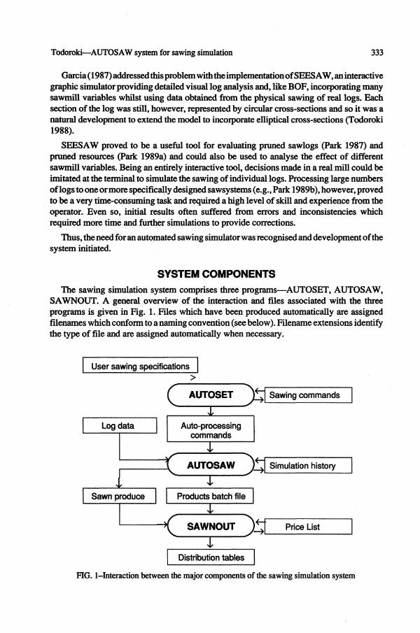
SYSTEM COMPONENTS The sawing simulation system comprises three programs—AUTOSET, AUTOSAW,
SAWNOUT. A general overview of the interaction and files associated with the three programs is given in Fig. 1. Files which have been produced automatically are assigned filenames which conform to a naming convention (see below). Filename extensions identify the type of file and are assigned automatically when necessary.
User sawing specifications
Sawing commands
Simulation history
Price List
j Distribution tables |
FIG. 1-Interaction between the major components of the sawing simulation system
Log data
i Sawn produce
c AUTOSET
x >
Auto-processing commands
c AUTOSAW y Products batch file
<
A. SAWNOUT J3
334 New Zealand Journal of Forestry Science 20(3)
The first of the three programs, AUTOSET, allows for the creation and/or modification of command files which contain the specifications for the sawing strategy and sawing pattern. These command files, together with one or more log data files, can be used directly as input to AUTOSAW, providing automated sawing simulation on the specified logs.
The primary output of AUTOSAW is a timber list of dimensioned and graded boards which are identified by the sequence in which they were produced and by the log of origin. This timber list is linked to any nominated pricelist and processed in SAWNOUT (Sawn Outturn) to produce tables of conversions, grades, and values for both individual logs and log batches.
The three programs are described in more detail below.
AUTOSET Program AUTOSET provides user directives for the selection of sawing patterns and for the
specification of sawing strategies. It also covers sawmill variables, some timber grading variables, log positioning, board dimensions, edging, and docking options.
Sawmill variables The sawmill variables are the carriage configuration, sawkerfs of the headrig and edger,
Timber grades At present the system recognises six timber grades. These, in order of priority, are: Clear
(denotedby"c"inFig. 2,3,4,5),Clear 1 Face("x"),No. 1 Cuttings("s"),No.2Cuttings("f"), Knotty ("k"), and Knotty With Pith ("p"). Either, or both, of the clearcutting grades may be redefined by the user. The number of clearcutting grades may be extended in future if the need arises.
Log positioning The log may be positioned with either the small end or the large end presented to the saw.
It may be either centred on the carriage or positioned at a user-specified distance from the front knee. Positioning for either half-taper or offset sawing is also catered for, as is positioning for sweep. Five basic options are provided for positioning for sweep—horns up, horns down, horns in, horns out, and rotation from horns down. The last option uses a user-specified angle to rotate the log from the horns down position. For example, with an angle of 0° the log will be in the same position as had the horns down option been selected; with an angle of 45° the log will be positioned such that it is halfway between the horns down and horns in positions.
Board dimensions There may be up to 10 width classes and four thickness classes specified for each sawing
pattern. Each thickness/width class requires an actual and a nominal thickness/width to be specified to accommodate overcutting.
Todoroki—AUTOS AW system for sawing simulation 335
FIG. 2-Example of "live" sawing. Grades are FIG. 3-Example of "cant" sawing (three sides), "c" Clear; "x" Clear 1 Face; "s" No.l Grades as for Fig. 2. Cuttings; "f" No.2 Cuttings; "k" Knotty; "p" Knotty With Pith.
LOG : TAS10 TK14.DAT automatically sawn with demo.AUT
FIG. 4-Example of "cant" sawing (four sides). FIG. 5-Example of "free cant" sawing. Grades Grades as for Fig. 2. as for Fig. 2.
Edging options At the time of writing, two possibilities for automated edging exist. These are edging for
length and edging for width. Both options make use of the above width classes. (With the former option selected, the AUTOS AW program maximises volume under a length constraint whilst the latter maximises volume under a width constraint.)
Sawing patterns The AUTOSET program has provision for both "cant" sawing and "live" sawing patterns.
Many variations on these sawing patterns are possible. In addition, cant sawing patterns can
336 New Zealand Journal of Forestry Science 20(3)
also be set up to enable the simulation of both automatically centred cants and free cants. Free cants require the seeking out of the position of the defect core. This is accommodated in the AUTOSET program by specifying a grade for each of the two sides of the cant. After the grade for each of the sides has been encountered (or exceeded) during the sawing simulation the appropriate cant size is selected and any necessary sizing cuts made. Results after simulation using various sawing patterns are demonstrated in Fig. 2-5—a "live" sawn log in Fig. 2, "free cant" sawing in Fig. 5, and "centred cant" sawing in Fig. 3 and 4. Some of the variations possible in the number of log faces are also indicated, with the sawing sequence and direction indicated by the flitch numbers.
Cant sizes There may be up to five cant thickness classes specified. Each thickness class requires an
actual and a nominal thickness to be specified, as for board dimensions. If the cant size is to be determined by the small-end diameter of the log, then small-end diameters corresponding to those cant sizes must be entered.
Sawing strategies Separate sawing strategies can be defined for each side of the sawing pattern encompassing
such considerations as selection of the opening cut, board thicknesses, incremental thickness changes, minimisation of wastage, and the criteria for turning the log to the next face. In addition, the following variations are possible.
Opening cuts: The opening cut can be specified at a certain position (determined by the dimensions of the face exposed to the saw) or at a position relative to the opposite face. The latter option makes provision for emulating the sawing of the opposite face, or for sawing boards of specific thicknesses upon meeting a dimensions constraint, or for maximising the boards' volume, or for maximising recovery for boards from the cant.
Board thicknesses and incremental changes: Any or all of the board thicknesses included in the board dimensions specifications may be used for sawing on each face. Incremental thickness changes may be specified to occur at a position determined by either the dimensions or the grade of the face exposed to the saw.
Sizing cuts I minimisation of wastage: The combination of sawing pattern and sawing strategy may create wastage on some faces. For each of these faces it is possible to elect to have wasteage minimised by allowing for alternative board thicknesses to be substituted.
Turning the log: Criteria for turning the log can be specified such that sawing of the exposed face is to cease if a specified dimension of face or grade is encountered, or exceeded, or after a specified number of flitches have been recovered.
Auto-processing Commands File This small but significant program module provides for the creation of new Auto-
processing Commands Files, or the modification of previous ones. The Auto-processing Commands File (Fig. 1) contains reference to the Sawing Commands File and also contains the number and filename of each of the logs to be processed by the sawing simulator, AUTOSAW.
Todoroki—AUTOSAW system for sawing simulation 337
AUTOSET summary The previous subsections describe the Sawing Commands File. These files may be saved,
or manipulated to imitate different sawing strategies, sawing patterns, and variations in mill parameters. Reference to the Sawing Commands File and to each of the log data files is stored in the Auto-processing Commands File.
AUTOSAW Program AUTOSAW may be used for both automated and interactive sawing simulations. An
overview of the AUTOSAW program is given in Fig. 6 in more detail than was given in Fig. 1.
For automated sawing simulations, an Auto-processing Command File contains directives to the appropriate sawing strategy specifications file and log data files. On the other hand, interactive sawing simulations require interactive use of function keys, with the user making decisions at each stage of the simulation, similar to those decisions made in a real mill. Both modes of operation provide sawing, edging, docking, and grading capabilities.
Log description Log data files contain descriptions of the log profile and defect core measured in two
planes. The external log profile is represented by elliptical cross-sections (Todoroki 1988) whilst whorls are represented as polygons (Garcia 1987).
fAUTOSAVlT
Log data
1
Simulation history
1 / \ 1 i / \
1 1 , f ^ ~
4, < * ,
Interactive processing
)
Auto-processing commands
I Ii Automated processing
i
1 1 I
Sawn produce
I Simulation
history
| L
I Log1 I data
1 Log n data
^ Products
batch
i Sawn 1 I produce j
» >
Simulation 1 history 1
y
I Sawn n T produce
t
J Simulation j history n
FIG. 6-An overview of the AUTOSAW program.
338 New Zealand Journal of Forestry Science 20(3)
Data were acquired from the physical sawing of real logs, described in more detail by Park (1987).
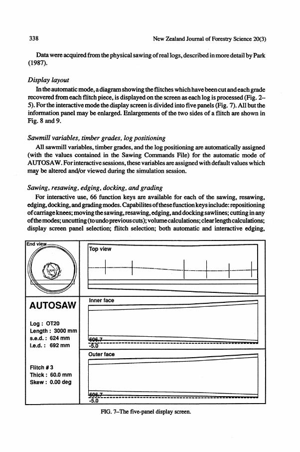
Display layout In the automatic mode, a diagram showing the flitches which have been cut and each grade
recovered from each flitch piece, is displayed on the screen as each log is processed (Fig. 2 -5). For the interactive mode the display screen is divided into five panels (Fig. 7). All but the information panel may be enlarged. Enlargements of the two sides of a flitch are shown in Fig. 8 and 9.
Sawmill variables, timber grades, log positioning All sawmill variables, timber grades, and the log positioning are automatically assigned
(with the values contained in the Sawing Commands File) for the automatic mode of AUTOS AW. For interactive sessions, these variables are assigned with default values which may be altered and/or viewed during the simulation session.
Sawing, resawing, edging, docking, and grading For interactive use, 66 function keys are available for each of the sawing, resawing,
edging, docking, and grading modes. Capabilites of these function keys include: repositioning of carriage knees; moving the sawing, resawing, edging, and docking sawlines; cutting in any of the modes; uncutting (to undo previous cuts); volume calculations; clear length calculations; display screen panel selection; flitch selection; both automatic and interactive edging,
Top view
AUTOSAW
Log : OT20 Length: 3000 mm s.e.d.: 624 mm l.e.d.: 692 mm
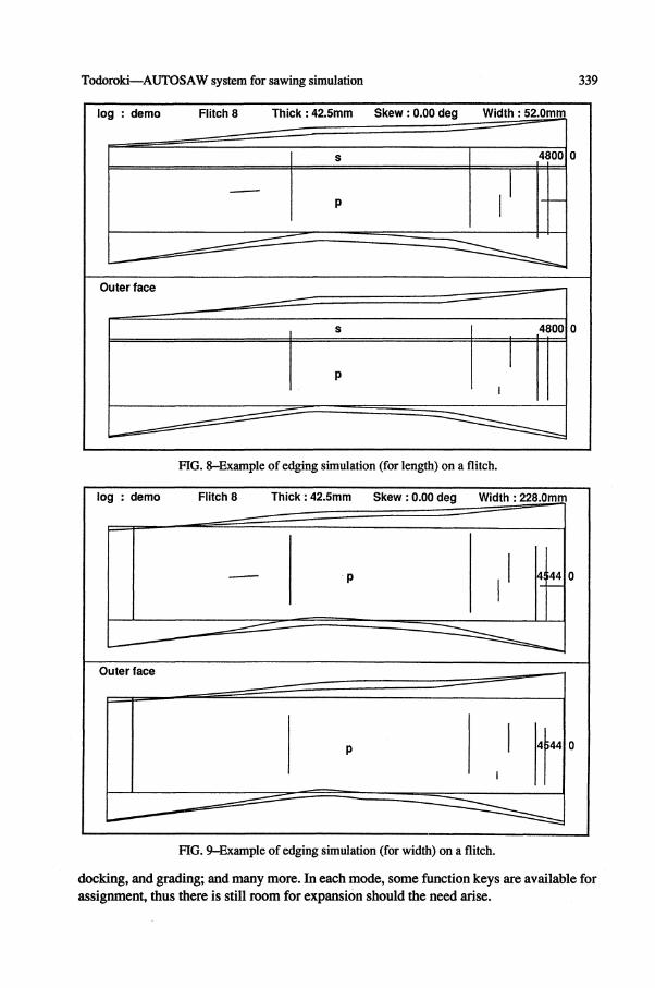
FIG. 9-Example of edging simulation (for width) on a flitch.
docking, and grading; and many more. In each mode, some function keys are available for assignment, thus there is still room for expansion should the need arise.
340 New Zealand Journal of Forestry Science 20(3)
Some of the function keys are described in more detail below.
Automatic edging: The complexity and number of iterations required to perform the automatic edging routine is, to a degree, dependent on the shape of the flitch. Ten routines (for each of the two types of edging as described in the AUTOSET program) are used to edge a flitch with up to seven routines being used on an "irregular" shaped flitch and up to three routines for a "regular" shaped flitch. For simplicity, a "regular" flitch is one for which 66% or more of one of the edges is straight. After the flitch has been automatically edged, the program automatically performs the docking and grading routines using the specified variables. An example of a flitch which has been automatically edged (for length), docked, and graded is shown in Fig. 8. For comparison, the same flitch automatically edged for width is shown in Fig. 9.
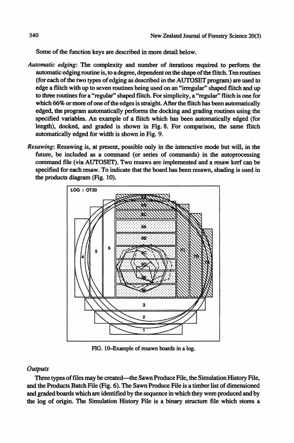
Resawing: Resawing is, at present, possible only in the interactive mode but will, in the future, be included as a command (or series of commands) in the autoprocessing command file (via AUTOSET). Two resaws are implemented and a resaw kerf can be specified for each resaw. To indicate that the board has been resawn, shading is used in the products diagram (Fig. 10).
FIG. 10-Example of resawn boards in a log.
Outputs Three types of files may be created—the Sawn Produce File, the Simulation History File,
and the Products Batch File (Fig. 6). The Sawn Produce File is a timber list of dimensioned and graded boards which are identified by the sequence in which they were produced and by the log of origin. The Simulation History File is a binary structure file which stores a
Todoroki—AUTOSAW system for sawing simulation 341
complete record of the sawing simulation session. It is produced for each log which is automatically sawn and is optional for interactive simulations. When used as input to AUTOSAW (see Fig. 6), this file provides a complete visual record of the simulation. The log's sawpattern can be viewed (Fig. 2-5 and 10) as can individual flitches (Fig. 8and9)and, in fact, any panel of the display screen may be viewed. In addition to viewing the simulation's history, it is also possible to continue with the sawing simulation (had it not been completed during an interactive session) or even to completely alter the previous session by using the function keys.
The Products Batch File is created only for the automated simulation. This file can be used directly as input to the SAWNOUT program (described below) and includes a reference to each of the Sawn Produce Files. Also included is the volume for each log of origin. This is required for calculation of conversions, volume residues, and clearcut length ratios in the SAWNOUT program. Each log volume is calculated using truncated cones up to 1.4 m from the large end, and thereafter paraboloids.
Naming conventions
The files represented in Fig. 1 and 6 have the following extensions.
FILE TYPE EXTENSION Log Data Sawn Produce Simulation History Sawing Commands Auto-processing Commands Products Batch Price List Distribution Tables
.DAT
.OUT
.CON
.LIV/.CAN
.AUT
.SWN
.PCE
.LIS
For automated simulations the resultant output files are assigned names which identify the Auto-processing Commands File from which they were created and the log of origin (by sequence number). The number is restricted to two digits thus up to 100 unique filenames for each type of file and for each automated simulation are possible. This is more than sufficient for present purposes.
Operation time Because the logs to be sawn contain varying degrees of complexity, i.e., the number of
log sections and number of defects (pith and whorls) differ from log to log, in addition to the variation possible in the actual sawpattern, no one time can be representative for the model. However, trials of 50 logs have produced times of between 6:32 min (all 50 logs having four sections only) and 13:10 min (all 50 logs having 15 sections), Le., 7.8 and 15.8 s/log, respectively. Times can be reduced further (by 10% or more) by not having the map of the sawing pattern and board grades displayed on the screen for each log as it is sawn.
Sawn Outturn Program Program S AWNOUT analyses the results of the sawing studies. Individual log conversions
and/or accumulated log conversions can be calculated. The 14 tables available for analysis are shown in Appendix 1. Tables may also be further subdivided into thickness classes.
342 New Zealand Journal of Forestry Science 20(3)
The S AWNOUT program requires input of a Price List which may be created or edited within the body of the program. Other input files (e.g., the Products Batch file from the AUTOSAW program) or individual sawn produce files can also be edited within the program, and a further facility allows real mill data to be entered directly at the keyboard.
Hardware and Software Considerations AH three programs run on IBM-compatible PCs under the MS-DOS operating system, are
coded in Pascal, and compiled using the Microsoft Compiler. The AUTOSAW program is linked with the HALO graphics library, thus a graphics card is required. A printer is optional.
APPLICATION AND FUTURE DEVELOPMENT AUTOSAW, in conjunction with SAWNOUT, is already proving useful for rapid
evaluation of pruned sawlogs as affected by log positioning, sawpattern, and sawing, edging, and docking procedures. Any number of simulations may be applied to individual logs providing extensive facilities for evaluating the outcome of variations in sawing and sawmill parameters.
As well as the obvious advantage provided by greatly increased performance, the simulation package provides the user with a consistent, reproducible model whilst still giving the flexibility and control required in the specification of parameters.
It is envisaged that AUTOSAW will be developed further, expanding its range of capabilities and flexibilty, with particular emphasis on areas such as edging and grading. The automated edging routines are the present limitations of the program and this problem will be addressed by implementation of a routine which will edge for specific board dimensions based on order of priority for the given sizes. Options for edging for grade are also planned.
ACKNOWLEDGMENTS The development ideas of J. Park and his in-depth knowledge of milling practices have been central
to the development of the simulation package. The valuable contributions and program validation by S. Wakelin are also gratefully acknowledged.
REFERENCES GARCIA, 0.1987: SEESAW: A visual sawing simulator. Part II: The SEESAW computer program.
Pp. 107-16 in Kininmonth, J. A. (Comp.) "Proceedings of the Conversion Planning Conference". Ministry of Forestry, FRI Bulletin No. 128.
LEBAN J.M.; DUCHANOIS, G. 1990: SIMQUA: Un logiciel de simulation de Ia qualite" du bois. Annales des Sciences Foresteriires 47: 483-93.
LEWIS D.W. 1985: Sawmill simulation and the Best Opening Face system: A user's guide. USDA Forest Service, Forest Products Laboratory, General Technical Report FPL-48. 1986: Best Opening Face system for sweepy, eccentric logs: A user's guide. USDA Forest Service, Forest Products Laboratory, General Technical Report FPL-49.
PARK, J.C. 1987: SEESAW: A visual sawing simulator. Part I: Data, methods, and program evaluation. Pp. 97-106 in Kininmonth, J. A. (Comp.) "Proceedings of the Conversion Planning Conference". Ministry of Forestry, FRI Bulletin No. 128. 1989a: Applications of the SEESAW simulator and Pruned Log Index to pruned resource
evaluations—A case study. New Zealand Journal of Forestry Science 19: 68-82. 1989b: Comparison, via the SEESAW simulator, of three sawing systems for pruned logs. New Zealand Journal of Forestry Science 19: 83-96.
PARK, J.C; LEMAN, CS. 1983: A sawing study method for evaluating timber from pruned logs. New Zealand Forest Service, FRI Bulletin No. 47.
SIGMIN, M. 1978: SIMSAW—A simulation program to evaluate the effect of sawing patterns on log recovery. Council for Scientific and Industrial Research Pretoria, Special Report HOUT156.
TODOROKI, CL. 1988: SEESAW: A visual sawing simulator, as developed in Version 3.0. New Zealand Journal of Forestry Science 18:116-23.
344 New Zealand Journal of Forestry Science 20(3)
APPENDIX 1
PRICE LIST 3. WASTE CREDIT $ 40.00
Grade
Pith Knotty No.2 Cuttings No.l Cuttings C 1 Face Clear Clearcuts
50
110.00 172.00 204.00 315.00 315.00 429.00 429.00
75
150.00 172.00 204.00 297.00 297.00 429.00 429.00
100
150.00 172.00 204.00 297.00 297.00 429.00 429.00
Width (mm)
150
165.00 172.00 234.00 309.00 309.00 429.00 429.00
200
165.00 183.00 238.00 309.00 309.00 472.00 472.00
250
172.00 183.00 272.00 352.00 352.00 472.00 472.00
300
175.00 183.00 272.00 352.00 352.00 472.00 472.00
GRADES AND THEIR RESPECTIVE ZONES
Grade Code Zone
Pith Knotty No.2 Cuttings No.l Cuttings C 1 Face Clear
P k f s X c
a b b b c
AUTOSAW V2.0 — DEMA.AUT RUN WITH DEMA.CAN
THICKNESS : 25 + 40 + 50 mm
TABLE 1—Grade by sizes sawn, number, and volume (vol. = m3 x IO"2) for log No. 1
Grade
Pith
Knotty
No.2 Cutt's
No.l Cutt's
C 1 Face
Clear
Total
50
0 0.00 0 0.00 0 0.00 0 0.00 0 0.00 0 0.00 0 0.00
75
0 0.00 0 0.00 0 0.00 0 0.00 0 0.00
13 9.53
13 9.53
100
0 0.00 0 0.00 0 0.00 0 0.00 0 0.00 5 4.20 5 4.20
Width (mm)
150 200
0 0.00 0 0.00 0 0.00 0 0.00 0 0.00 4
10.02 4
10.02
0 0.00 0 0.00 0 0.00 0 0.00 0 0.00 5
18.06 5
18.06
250
2 9.45 2
10.50 1 5.25 0 0.00 5
21.00 6
25.20 6
71.40
300
0 0.00 0 0.00 0 0.00 0 0.00 0 0.00 0 0.00 0 0.00
Total
2 9.45 2
10.50 1 5.25 0 0.00 5
21.00 33 67.01 43
113.21
lututittt 0 4 > b o t o o \ 0 4 > b o t o o \
o o o o o o o o o o o
88883888388
p o o o S v o o t v o o o o l O O O Q Q W ^ V O H - Q Q Q