22
September 2008 AutoSketch 10 Create a Birdhouse Drawing ®
September 2008
AutoSketch 10Create a Birdhouse Drawing
®
© 2008 Autodesk, Inc. All rights reserved. Except as otherwise permitted by Autodesk, Inc., this publication, or parts thereof, maynot be reproduced in any form, by any method, for any purpose.
Certain materials included in this publication are reprinted with the permission of the copyright holder.
Trademarks
The following are registered trademarks or trademarks of Autodesk, Inc., in the USA and other countries: 3DEC (design/logo),3December, 3December.com, 3ds Max, ADI, Alias, Alias (swirl design/logo), AliasStudio, Alias|Wavefront (design/logo), ATC, AUGI,AutoCAD, AutoCAD Learning Assistance, AutoCAD LT, AutoCAD Simulator, AutoCAD SQL Extension, AutoCAD SQL Interface,Autodesk, Autodesk Envision, Autodesk Insight, Autodesk Intent, Autodesk Inventor, Autodesk Map, Autodesk MapGuide, AutodeskStreamline, AutoLISP, AutoSnap, AutoSketch, AutoTrack, Backdraft, Built with ObjectARX (logo), Burn, Buzzsaw, CAiCE, Can YouImagine, Character Studio, Cinestream, Civil 3D, Cleaner, Cleaner Central, ClearScale, Colour Warper, Combustion, CommunicationSpecification, Constructware, Content Explorer, Create>what's>Next> (design/logo), Dancing Baby (image), DesignCenter, DesignDoctor, Designer's Toolkit, DesignKids, DesignProf, DesignServer, DesignStudio, Design|Studio (design/logo), Design Web Format,DWF, DWG, DWG (logo), DWG Extreme, DWG TrueConvert, DWG TrueView, DXF, Ecotect, Exposure, Extending the Design Team,FBX, Filmbox, FMDesktop, Freewheel, GDX Driver, Gmax, Green Building Studio, Heads-up Design, Heidi, HumanIK, IDEA Server, i-drop, ImageModeler, iMOUT, Incinerator, Inventor, Inventor LT, Kaydara, Kaydara (design/logo), Kynapse, Kynogon, LandXplorer,LocationLogic, Lustre, Matchmover, Maya, Mechanical Desktop, MotionBuilder, Movimento, Mudbox, NavisWorks, ObjectARX,ObjectDBX, Open Reality, Opticore, Opticore Opus, PolarSnap, PortfolioWall, Powered with Autodesk Technology, Productstream,ProjectPoint, ProMaterials, RasterDWG, Reactor, RealDWG, Real-time Roto, REALVIZ, Recognize, Render Queue, Retimer,Reveal, Revit,Showcase, ShowMotion, SketchBook, SteeringWheels, Stitcher, StudioTools, Topobase, Toxik, TrustedDWG, ViewCube, Visual, VisualConstruction, Visual Drainage, Visual Landscape, Visual Survey, Visual Toolbox, Visual LISP, Voice Reality, Volo, Vtour, Wiretap, andWiretapCentral.
The following are registered trademarks or trademarks of Autodesk Canada Co. in the USA and/or Canada and other countries:Backburner, Discreet, Fire, Flame, Flint, Frost, Inferno, Multi-Master Editing, River, Smoke, Sparks, Stone, and Wire.
The following are registered trademarks or trademarks of Moldflow Corp. in the USA and/or other countries: Moldflow
MPA, MPA (design/logo), Moldflow Plastics Advisers, MPI, MPI (design/logo), Moldflow Plastics Insight, MPX, MPX (design/logo),Moldflow Plastics Xpert.
All other brand names, product names or trademarks belong to their respective holders.
Disclaimer
THIS PUBLICATION AND THE INFORMATION CONTAINED HEREIN IS MADE AVAILABLE BY AUTODESK, INC. "AS IS." AUTODESK, INC.,DISCLAIMS ALL WARRANTIES, EITHER EXPRESS OR IMPLIED, INCLUDING BUT NOT LIMITED TO ANY IMPLIED WARRANTIES OFMERCHANTABILITY OR FITNESS FOR A PARTICULAR PURPOSE REGARDING THESE MATERIALS.
Published by:
Autodesk, Inc. 111 Mclnnis Parkway San Rafael, CA 94903, USA
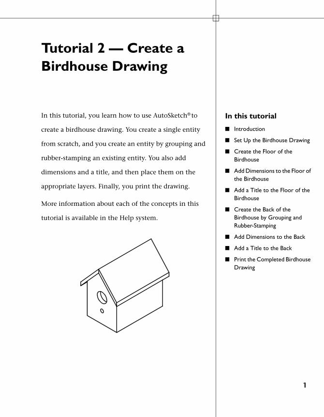
Tutorial 2 — Create a Birdhouse Drawing
In this tutorial
■ Introduction
■ Set Up the Birdhouse Drawing
■ Create the Floor of the Birdhouse
■ Add Dimensions to the Floor of the Birdhouse
■ Add a Title to the Floor of the Birdhouse
■ Create the Back of the Birdhouse by Grouping and Rubber-Stamping
■ Add Dimensions to the Back
■ Add a Title to the Back
■ Print the Completed Birdhouse Drawing
In this tutorial, you learn how to use AutoSketch® to
create a birdhouse drawing. You create a single entity
from scratch, and you create an entity by grouping and
rubber-stamping an existing entity. You also add
dimensions and a title, and then place them on the
appropriate layers. Finally, you print the drawing.
More information about each of the concepts in this
tutorial is available in the Help system.
1

Introduction
Before you start drawing, make sure the drawing setup works for your needs. Consider the page size, page layout, scale, grid, layers, and so on.
Once you set up your drawing, you can begin to draw entities, move them to fit the page, set dimensions, and enter annotations. By the time you have completed this exercise, you will have created a drawing that you can use to build an actual birdhouse.
Note At the end of each exercise, you can take a break or move to the next exercise. Be sure to save your work at the end of each exercise, because each subsequent exercise builds on the one before it.
Set Up the Birdhouse Drawing
Before you create the birdhouse, make sure your drawing is properly set up. You can set up the Birdhouse drawing by resetting the interface to its original state.
In this exercise, you learn to
❒ Open a drawing.❒ Reset the interface.
To set up the Birdhouse drawing
1 On the File menu, click Open.
2 In the Open dialog box, navigate to the following location:
C:\Program Files\Autodesk\AutoSketch10\Drawings
2 | Tutorial 2 — Create a Birdhouse Drawing
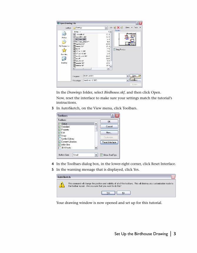
In the Drawings folder, select Birdhouse.skf, and then click Open.
Now, reset the interface to make sure your settings match the tutorial’s instructions.
3 In AutoSketch, on the View menu, click Toolbars.
4 In the Toolbars dialog box, in the lower-right corner, click Reset Interface.
5 In the warning message that is displayed, click Yes.
Your drawing window is now opened and set up for this tutorial.
Set Up the Birdhouse Drawing | 3
Create the Floor of the Birdhouse
In this exercise, you learn to
❒ Rename and save the drawing file. ❒ Zoom in to a section of a drawing.❒ Use the Absolute Coordinates dial to place an entity precisely.❒ Set line widths.
In the drawing for this tutorial, entities already exist for the back, roof, and sides of the birdhouse. In this exercise, save the drawing file, and then create a rectangular entity that represents the floor of the birdhouse.
To create the birdhouse floor
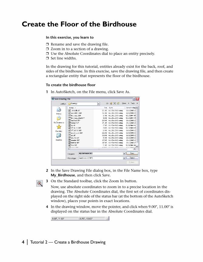
1 In AutoSketch, on the File menu, click Save As.
2 In the Save Drawing File dialog box, in the File Name box, type My_Birdhouse, and then click Save.
3 On the Standard toolbar, click the Zoom In button.
Now, use absolute coordinates to zoom in to a precise location in the drawing. The Absolute Coordinates dial, the first set of coordinates dis-played on the right side of the status bar (at the bottom of the AutoSketch window), places your points in exact locations.
4 In the drawing window, move the pointer, and click when 9.00", 11.00" is displayed on the status bar in the Absolute Coordinates dial.
4 | Tutorial 2 — Create a Birdhouse Drawing
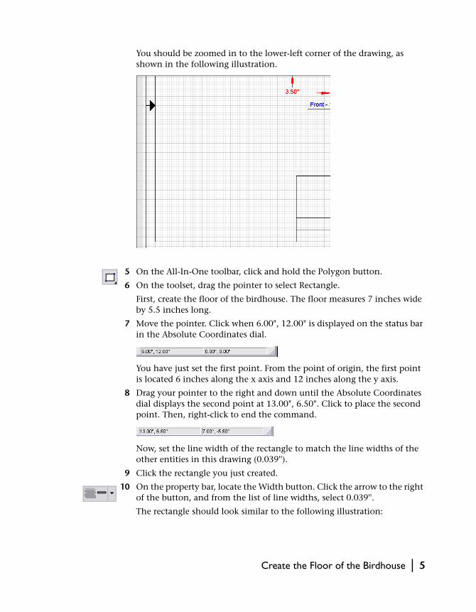
You should be zoomed in to the lower-left corner of the drawing, as shown in the following illustration.
5 On the All-In-One toolbar, click and hold the Polygon button.
6 On the toolset, drag the pointer to select Rectangle.
First, create the floor of the birdhouse. The floor measures 7 inches wide by 5.5 inches long.
7 Move the pointer. Click when 6.00", 12.00" is displayed on the status bar in the Absolute Coordinates dial.
You have just set the first point. From the point of origin, the first point is located 6 inches along the x axis and 12 inches along the y axis.
8 Drag your pointer to the right and down until the Absolute Coordinates dial displays the second point at 13.00", 6.50". Click to place the second point. Then, right-click to end the command.
Now, set the line width of the rectangle to match the line widths of the other entities in this drawing (0.039'').
9 Click the rectangle you just created.
10 On the property bar, locate the Width button. Click the arrow to the right of the button, and from the list of line widths, select 0.039''.
The rectangle should look similar to the following illustration:
Create the Floor of the Birdhouse | 5
11 On the File menu, click Save. Do not close the drawing.
Add Dimensions to the Floor of the Birdhouse
In this exercise, you learn to
❒ Add horizontal and vertical dimensions.❒ Move a dimension closer to its entity.❒ Place dimensions on the Dimensions layer.
You have just created the first entity for the birdhouse. Next, add dimensions to the drawing.
To add dimensions to the birdhouse floor
1 On the All-In-One toolbar, click and hold the Dimension button.
2 On the toolset, drag the pointer to select Horizontal Dimension.
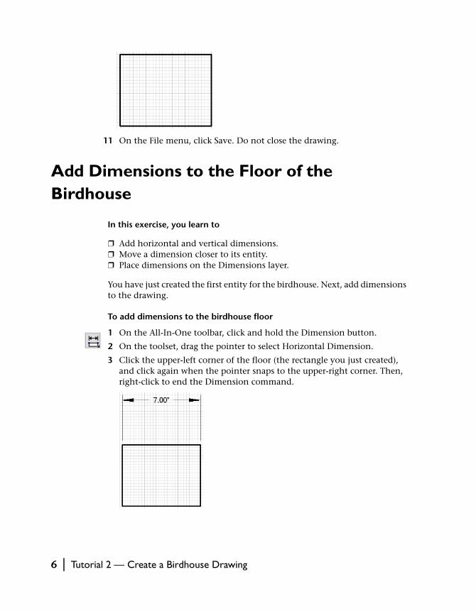
3 Click the upper-left corner of the floor (the rectangle you just created), and click again when the pointer snaps to the upper-right corner. Then, right-click to end the Dimension command.
6 | Tutorial 2 — Create a Birdhouse Drawing

You have just created the horizontal dimension. Now, move the dimen-sion closer to the rectangle.
4 Click the dimension you just created.
5 Click and hold the green triangle at the top of the selected dimension, and drag the pointer down until the dimension is closer to the rectangle. Then, release the mouse button.
The dimension placement should look similar to the following illustration:
The dimension should still be selected (you did not right-click to end the command). You can now place the dimension on the Dimensions layer.
6 On the property bar, locate the Layer button. Click the arrow to the right of the current layer, and then select Dimensions.
7 Click to the right of the dimension to deselect it.
Notice that the dimension is now red, the same color as the other dimen-sions in this drawing.
Note Now that the Dimensions layer is active, any entities you create are placed on the Dimensions layer until you change the layer. You learn more about how to change layers later.
Next, create the vertical dimension.
8 On the All-In-One toolbar, click and hold the Horizontal Dimension button.
9 On the toolset, drag the pointer to select Vertical Dimension.
Add Dimensions to the Floor of the Birdhouse | 7
10 Click the lower-left corner of the floor, and drag the pointer up until you snap to the upper-left corner. Click to set the vertical dimension. Then, right-click to end the command.
11 Click the dimension you just created. Then, click and hold the arrow to the left of the dimension, and drag the pointer to the right until you can place the dimension closer to the line you just dimensioned.
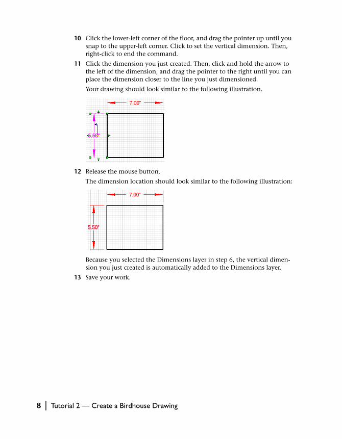
Your drawing should look similar to the following illustration.
12 Release the mouse button.
The dimension location should look similar to the following illustration:
Because you selected the Dimensions layer in step 6, the vertical dimen-sion you just created is automatically added to the Dimensions layer.
13 Save your work.
8 | Tutorial 2 — Create a Birdhouse Drawing
Add a Title to the Floor of the Birdhouse
In this exercise, you learn to
❒ Add a title to an entity.❒ Adjust the text height using the edit bar.❒ Add a line below the title.❒ Adjust the line width using the property bar.❒ Place the title on the Notes layer.
When you add a title to an entity, use the edit bar.
Add a title and place it on the Notes layer
1 On the All-In-One toolbar, click and hold the Text button.
2 On the toolset, drag the pointer to select Text Point.
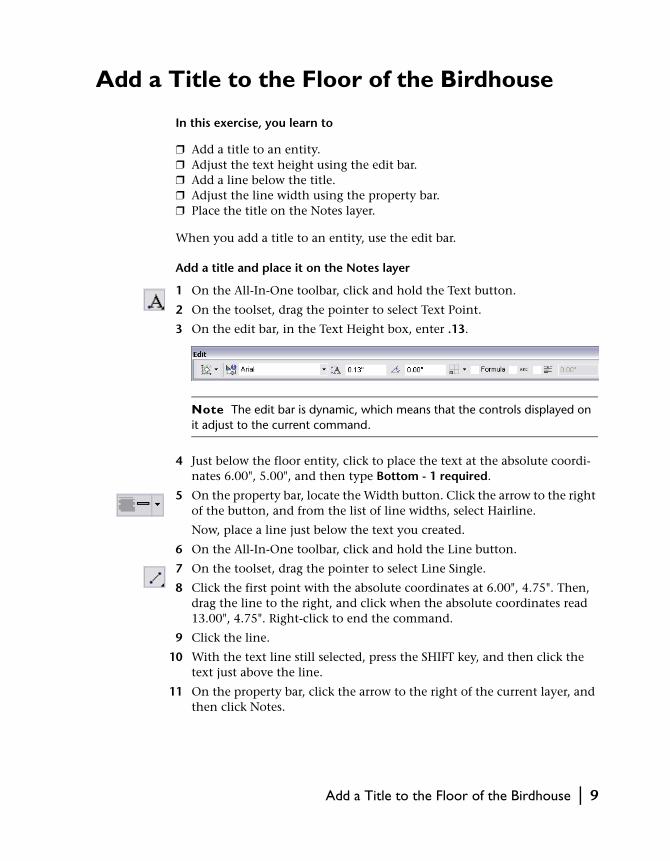
3 On the edit bar, in the Text Height box, enter .13.
Note The edit bar is dynamic, which means that the controls displayed on it adjust to the current command.
4 Just below the floor entity, click to place the text at the absolute coordi-nates 6.00", 5.00", and then type Bottom - 1 required.
5 On the property bar, locate the Width button. Click the arrow to the right of the button, and from the list of line widths, select Hairline.
Now, place a line just below the text you created.
6 On the All-In-One toolbar, click and hold the Line button.
7 On the toolset, drag the pointer to select Line Single.
8 Click the first point with the absolute coordinates at 6.00", 4.75". Then, drag the line to the right, and click when the absolute coordinates read 13.00", 4.75". Right-click to end the command.
9 Click the line.
10 With the text line still selected, press the SHIFT key, and then click the text just above the line.
11 On the property bar, click the arrow to the right of the current layer, and then click Notes.
Add a Title to the Floor of the Birdhouse | 9
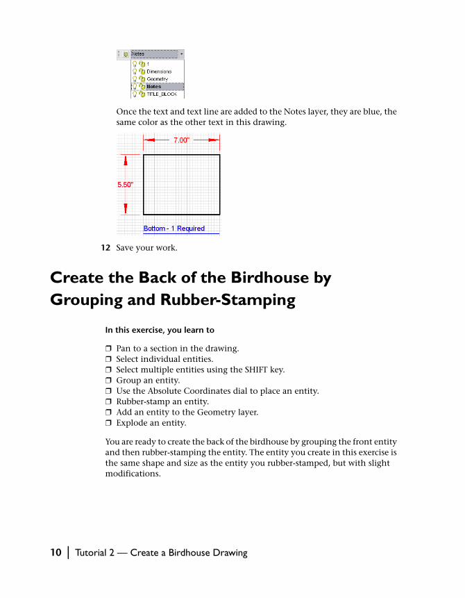
Once the text and text line are added to the Notes layer, they are blue, the same color as the other text in this drawing.
12 Save your work.
Create the Back of the Birdhouse by Grouping and Rubber-Stamping
In this exercise, you learn to
❒ Pan to a section in the drawing.❒ Select individual entities.❒ Select multiple entities using the SHIFT key.❒ Group an entity.❒ Use the Absolute Coordinates dial to place an entity.❒ Rubber-stamp an entity.❒ Add an entity to the Geometry layer.❒ Explode an entity.
You are ready to create the back of the birdhouse by grouping the front entity and then rubber-stamping the entity. The entity you create in this exercise is the same shape and size as the entity you rubber-stamped, but with slight modifications.
10 | Tutorial 2 — Create a Birdhouse Drawing
To group the front
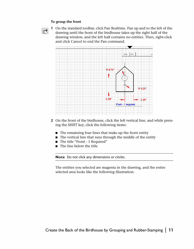
1 On the standard toolbar, click Pan Realtime. Pan up and to the left of the drawing until the front of the birdhouse takes up the right half of the drawing window, and the left half contains no entities. Then, right-click and click Cancel to end the Pan command.
2 On the front of the birdhouse, click the left vertical line, and while press-ing the SHIFT key, click the following items:
■ The remaining four lines that make up the front entity■ The vertical line that runs through the middle of the entity■ The title “Front - 1 Required” ■ The line below the title
Note Do not click any dimensions or circles.
The entities you selected are magenta in the drawing, and the entire selected area looks like the following illustration:
Create the Back of the Birdhouse by Grouping and Rubber-Stamping | 11

3 Right-click any of the selected entities, and then click Group.
The items you selected are grouped into a new, single entity. You can now duplicate the grouped entity by using a tool called the rubber stamp.
4 With the grouped entity still selected, on the All-In-One toolbar, click the Rubber Stamp button.
5 Move the pointer to the left of the entity you just selected. Click when 9.00", 22.00" is displayed in the Absolute Coordinates dial, and then right-click to end the Rubber Stamp command.
You have just created a new entity that has the same properties as the orig-inal entity. Place the entity on the Geometry layer.
6 Click the grouped entity.
7 On the property bar, click the arrow to the right of the current layer, and then select Geometry.
12 | Tutorial 2 — Create a Birdhouse Drawing
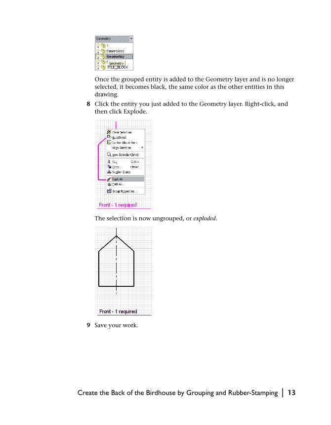
Once the grouped entity is added to the Geometry layer and is no longer selected, it becomes black, the same color as the other entities in this drawing.
8 Click the entity you just added to the Geometry layer. Right-click, and then click Explode.
The selection is now ungrouped, or exploded.
9 Save your work.
Create the Back of the Birdhouse by Grouping and Rubber-Stamping | 13
Add Dimensions to the Back
In this exercise, you learn to
❒ Add horizontal and vertical dimensions.❒ Move a dimension closer to its entity.❒ Add an angular dimension.❒ Select multiple entities using the SHIFT key.❒ Place dimensions on the Dimensions layer.
In an earlier exercise in this tutorial, you learned how to create dimensions and add them to the Dimensions layer. Now, in addition to horizontal and vertical dimensions, you create an angular dimension for the birdhouse roof.
To add dimensions to the back
1 On the All-In-One toolbar, click and hold the Dimension button.
2 On the toolset, drag the pointer to select Horizontal Dimension.
3 Click the lower-left corner of the entity.
4 Press and hold the CTRL key, and then move the pointer until it snaps to the lower-right corner.
5 Right-click to end the command.
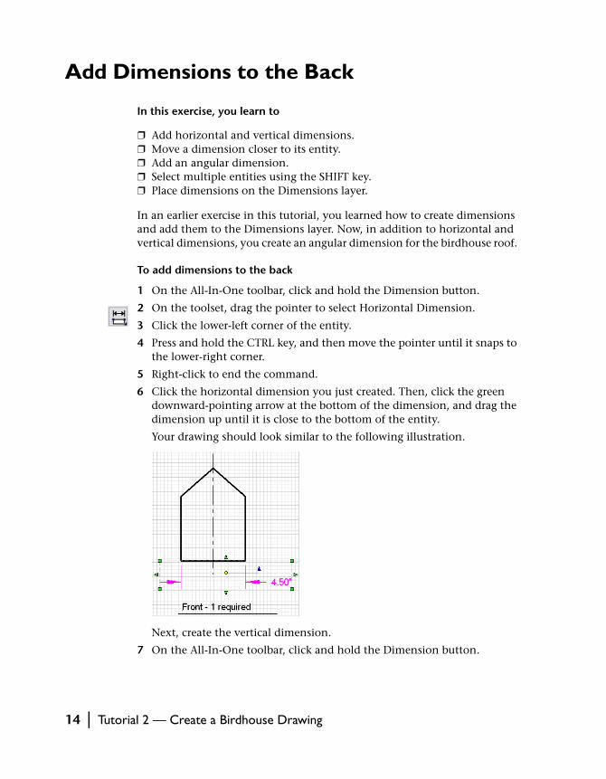
6 Click the horizontal dimension you just created. Then, click the green downward-pointing arrow at the bottom of the dimension, and drag the dimension up until it is close to the bottom of the entity.
Your drawing should look similar to the following illustration.
Next, create the vertical dimension.
7 On the All-In-One toolbar, click and hold the Dimension button.
14 | Tutorial 2 — Create a Birdhouse Drawing
8 On the toolset, drag the pointer to select Vertical Dimension.
9 Click the lower-left corner of the entity, and drag the pointer up until you snap to the upper-left corner. Click to set the vertical dimension.
You need to move the dimension closer to the entity.
Note You may need to pan to the left a little to see the dimension.
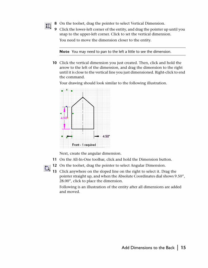
10 Click the vertical dimension you just created. Then, click and hold the arrow to the left of the dimension, and drag the dimension to the right until it is close to the vertical line you just dimensioned. Right-click to end the command.
Your drawing should look similar to the following illustration.
Next, create the angular dimension.
11 On the All-In-One toolbar, click and hold the Dimension button.
12 On the toolset, drag the pointer to select Angular Dimension.
13 Click anywhere on the sloped line on the right to select it. Drag the pointer straight up, and when the Absolute Coordinates dial shows 9.50”, 28.00”, click to place the dimension.
Following is an illustration of the entity after all dimensions are added and moved.
Add Dimensions to the Back | 15

Now, place the dimensions on the Dimensions layer.
14 While holding the SHIFT key, click all three dimensions.
15 On the property bar, locate the Layer button. Click the arrow to the right of the current layer, and then select Dimensions.
16 Click to the right of the entity.
Once the dimensions are added to the Dimensions layer, they are red, the same color as the other dimensions in this drawing.
17 Save your work.
16 | Tutorial 2 — Create a Birdhouse Drawing
Add a Title to the Back
In this exercise, you learn to
❒ Add a title to the back entity by editing an existing title.❒ Add the new title to the Notes layer.
Add a title to the back
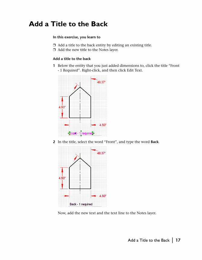
1 Below the entity that you just added dimensions to, click the title “Front - 1 Required”. Right-click, and then click Edit Text.
2 In the title, select the word “Front”, and type the word Back.
Now, add the new text and the text line to the Notes layer.
Add a Title to the Back | 17

3 Click the text line, press the SHIFT key, and then click the text just above the line.
4 On the property bar, click the arrow to the right of the current layer, and then select Notes.
5 Save your work.
You have completed the birdhouse drawing.
Print the Completed Birdhouse Drawing
In this exercise, you learn to
❒ Set up the drawing for printing.❒ Print the drawing.
In the final exercise of this tutorial, you can print the completed birdhouse drawing to see all the work that you’ve done.
To print a drawing
1 On the File menu, click Print.
2 In the Print dialog box, change the following settings:
■ In the View to Print drop-down list, click Page View.■ In the Sizing Method drop-down list, click Scaled.■ (Optional) To print the grid, click the check box next to Print Grid.
18 | Tutorial 2 — Create a Birdhouse Drawing
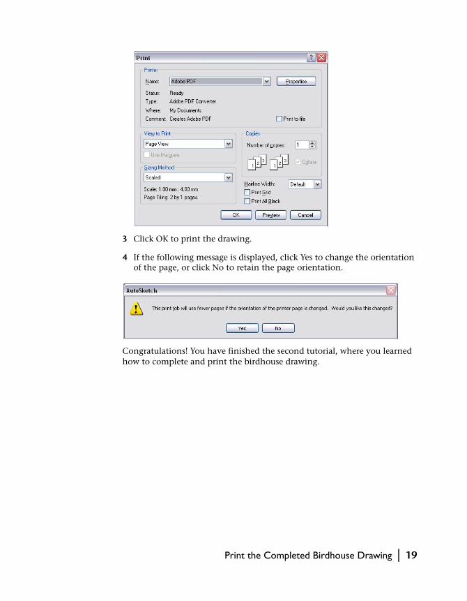
3 Click OK to print the drawing.
4 If the following message is displayed, click Yes to change the orientation of the page, or click No to retain the page orientation.
Congratulations! You have finished the second tutorial, where you learned how to complete and print the birdhouse drawing.
Print the Completed Birdhouse Drawing | 19

20


