248
Installation and Configuration for the Avaya C360 Converged Stackable Switches Software Version 4.5 10-300503 Issue 2 July 2005
Installation and Configuration for the Avaya C360 Converged Stackable SwitchesSoftware Version 4.5
10-300503Issue 2
July 2005
Copyright 2005, Avaya Inc.All Rights Reserved
NoticeEvery effort was made to ensure that the information in this document was complete and accurate at the time of printing. However, information is subject to change.
WarrantyAvaya Inc. provides a limited warranty on this product. Refer to your sales agreement to establish the terms of the limited warranty. In addition, Avaya’s standard warranty language as well as information regarding support for this product, while under warranty, is available through the following Web site: http://http://support.avaya.com.
DisclaimerAvaya is not responsible for any modifications, additions or deletions to the original published version of this documentation unless such modifications, additions or deletions were performed by Avaya. Customer and/or End User agree to indemnify and hold harmless Avaya, Avaya's agents, servants and employees against all claims, lawsuits, demands and judgments arising out of, or in connection with, subsequent modifications, additions or deletions to this documentation to the extent made by the Customer or End User.
How to Get HelpFor additional support telephone numbers, go to the Avaya support Web site: http://http://support.avaya.com. If you are:
• Within the United States, click the Escalation Management link. Then click the appropriate link for the type of support you need.
• Outside the United States, click the Escalation Management link. Then click the International Services link that includes telephone numbers for the international Centers of Excellence.
Standards ComplianceAvaya Inc. is not responsible for any radio or television interference caused by unauthorized modifications of this equipment or the substitution or attachment of connecting cables and equipment other than those specified by Avaya Inc. The correction of interference caused by such unauthorized modifications, substitution or attachment will be the responsibility of the user. Pursuant to Part 15 of the Federal Communications Commission (FCC) Rules, the user is cautioned that changes or modifications not expressly approved by Avaya Inc. could void the user’s authority to operate this equipment.
Product Safety StandardsThis product complies with and conforms to the following international Product Safety standards as applicable:Safety of Information Technology Equipment, IEC 60950, 3rd Edition, or IEC 60950-1, 1st Edition, including all relevant national deviations as listed in Compliance with IEC for Electrical Equipment (IECEE) CB-96A.Safety of Information Technology Equipment, CAN/CSA-C22.2No. 60950-00 / UL 60950, 3rd Edition, or CAN/CSA-C22.2 No. 60950-1-03 / UL 60950-1.One or more of the following Mexican national standards, as applicable: NOM 001 SCFI 1993, NOM SCFI 016 1993, NOM 019 SCFI 1998.The equipment described in this document may contain Class 1 LASER Device(s). These devices comply with the following standards:
• EN 60825-1, Edition 1.1, 1998-01• 21 CFR 1040.10 and CFR 1040.11.
The LASER devices used in Avaya equipment typically operate within the following parameters:
Luokan 1 LaserlaiteKlass 1 Laser ApparatUse of controls or adjustments or performance of procedures other than those specified herein may result in hazardous radiation exposures. Contact your Avaya representative for more laser product information.
Electromagnetic Compatibility (EMC) StandardsThis product complies with and conforms to the following international EMC standards and all relevant national deviations:Limits and Methods of Measurement of Radio Interference of Information Technology Equipment, CISPR 22:1997 and EN55022:1998.Information Technology Equipment – Immunity Characteristics – Limits and Methods of Measurement, CISPR 24:1997 and EN55024:1998, including:
• Electrostatic Discharge (ESD) IEC 61000-4-2• Radiated Immunity IEC 61000-4-3• Electrical Fast Transient IEC 61000-4-4• Lightning Effects IEC 61000-4-5• Conducted Immunity IEC 61000-4-6• Mains Frequency Magnetic Field IEC 61000-4-8• Voltage Dips and Variations IEC 61000-4-11
Power Line Emissions, IEC 61000-3-2: Electromagnetic compatibility (EMC) – Part 3-2: Limits – Limits for harmonic current emissions.Power Line Emissions, IEC 61000-3-3: Electromagnetic compatibility (EMC) – Part 3-3: Limits – Limitation of voltage changes, voltage fluctuations and flicker in public low-voltage supply systems.
Federal Communications Commission StatementPart 15:
Canadian Department of Communications (DOC) Interference InformationThis Class A digital apparatus complies with Canadian ICES-003.Cet appareil numérique de la classe A est conforme à la normeNMB-003 du Canada.
European Union Declarations of Conformity
Avaya Inc. declares that the equipment specified in this document bearing the “CE” (Conformité Europeénne) mark conforms to the European Union Electromagnetic Compatibility Directive (89/336/EEC) and Low Voltage Directive (73/23/EEC). Copies of these Declarations of Conformity (DoCs) can be obtained by contacting your local sales representative and are available on the following Web site: http://http://support.avaya.com.
JapanThis is a Class A product based on the standard of the Voluntary Control Council for Interference by Information Technology Equipment (VCCI). If this equipment is used in a domestic environment, radio disturbance may occur, in which case, the user may be required to take corrective actions.
To order copies of this and other documents:Call: Avaya Publications Center
Voice 1.800.457.1235 or 1.207.866.6701FAX 1.800.457.1764 or 1.207.626.7269
Write: Globalware Solutions200 Ward Hill AvenueHaverhill, MA 01835 USAAttention: Avaya Account Management
E-mail: [email protected] the most current versions of documentation, go to the Avaya support Web site: http://http://support.avaya.com.
Typical Center Wavelength Maximum Output Power830 nm - 860 nm -1.5 dBm1270 nm - 1360 nm -3.0 dBm1540 nm - 1570 nm 5.0 dBm
Note: This equipment has been tested and found to comply with the limits for a Class A digital device, pursuant to Part 15 of the FCC Rules. These limits are designed to provide reasonable protection against harmful interference when the equipment is operated in a commercial environment. This equipment generates, uses, and can radiate radio frequency energy and, if not installed and used in accordance with the instruction manual, may cause harmful interference to radio communications. Operation of this equipment in a residential area is likely to cause harmful interference in which case the user will be required to correct the interference at his own expense.
Issue 2 July 2005 3
Before you Install the Avaya C360 . . . . . . . . . . . . . . . . . . . . . 13Safety Information . . . . . . . . . . . . . . . . . . . . . . . . . . . . . . . . . . . 13Conventions Used in the Documentation . . . . . . . . . . . . . . . . . . . . . . 14
CLI Conventions . . . . . . . . . . . . . . . . . . . . . . . . . . . . . . . . . . 14Notes, Cautions, and Warnings. . . . . . . . . . . . . . . . . . . . . . . . . . 15
Section 1: Avaya C360 Overview . . . . . . . . . . . . . . . . . . . 17
Chapter 1: Avaya C360 Overview. . . . . . . . . . . . . . . . . . . . . . 19C360 Features and Benefits. . . . . . . . . . . . . . . . . . . . . . . . . . . . . . 20
Stacking . . . . . . . . . . . . . . . . . . . . . . . . . . . . . . . . . . . . . . 20Network Optimization . . . . . . . . . . . . . . . . . . . . . . . . . . . . . . . 20Manageability . . . . . . . . . . . . . . . . . . . . . . . . . . . . . . . . . . . 21Redundancy . . . . . . . . . . . . . . . . . . . . . . . . . . . . . . . . . . . . 21VLAN Support . . . . . . . . . . . . . . . . . . . . . . . . . . . . . . . . . . . 22Security. . . . . . . . . . . . . . . . . . . . . . . . . . . . . . . . . . . . . . . 23Quality of Service (QoS) . . . . . . . . . . . . . . . . . . . . . . . . . . . . . 23Monitoring . . . . . . . . . . . . . . . . . . . . . . . . . . . . . . . . . . . . . 24Power over Ethernet (PoE) Support on C360-PWR switches . . . . . . . . . . 24Layer 3 Support . . . . . . . . . . . . . . . . . . . . . . . . . . . . . . . . . . 25Management . . . . . . . . . . . . . . . . . . . . . . . . . . . . . . . . . . . . 25
Management Interface Options . . . . . . . . . . . . . . . . . . . . . . . . 26C360 Switch Configurations . . . . . . . . . . . . . . . . . . . . . . . . . . . . . 27
Section 2: Installing the C360 . . . . . . . . . . . . . . . . . . . . . 29
Chapter 2: Avaya C360 Front and Rear Panels . . . . . . . . . . . . . . 31C360 Front Panels . . . . . . . . . . . . . . . . . . . . . . . . . . . . . . . . . . . 32C360 Rear Panel . . . . . . . . . . . . . . . . . . . . . . . . . . . . . . . . . . . . 37
Chapter 3: Installation. . . . . . . . . . . . . . . . . . . . . . . . . . . . 39Preparing Needed Tools . . . . . . . . . . . . . . . . . . . . . . . . . . . . . . . . 39Site Preparation . . . . . . . . . . . . . . . . . . . . . . . . . . . . . . . . . . . . 40Rack Mounting (Optional) . . . . . . . . . . . . . . . . . . . . . . . . . . . . . . . 42
Before you Install the C360 in a Rack . . . . . . . . . . . . . . . . . . . . . . 42Wall Mounting (Optional) . . . . . . . . . . . . . . . . . . . . . . . . . . . . . . . 44Stacking (optional). . . . . . . . . . . . . . . . . . . . . . . . . . . . . . . . . . . 45
Installing the X360STK Stacking Module. . . . . . . . . . . . . . . . . . . . . 45
Contents
Contents
4 Installation and Configuration Guide Avaya C360 Multilayer Stackable Switches, version 4.5
Inter-Connecting Switches . . . . . . . . . . . . . . . . . . . . . . . . . . . . 46To connect stacked switches: . . . . . . . . . . . . . . . . . . . . . . . . 46
Making Connections to Network Equipment. . . . . . . . . . . . . . . . . . . . . 48Prerequisites . . . . . . . . . . . . . . . . . . . . . . . . . . . . . . . . . . . . 48Connecting Cables to Network Equipment . . . . . . . . . . . . . . . . . . . 48
Installing SFP GBIC Transceivers . . . . . . . . . . . . . . . . . . . . . . . . . . 49Safety Information . . . . . . . . . . . . . . . . . . . . . . . . . . . . . . . . . 49
Usage Restriction . . . . . . . . . . . . . . . . . . . . . . . . . . . . . . . 49Installing and Removing a SFP GBIC Transceiver . . . . . . . . . . . . . . . 50
Copper GBIC Transceiver Installation Notes . . . . . . . . . . . . . . . . 51
Chapter 4: Powering Up the Avaya C360 . . . . . . . . . . . . . . . . . 53Connecting to an AC Power Supply . . . . . . . . . . . . . . . . . . . . . . . . . 54
AC Power Cable . . . . . . . . . . . . . . . . . . . . . . . . . . . . . . . . . . 54Connecting a BUPS . . . . . . . . . . . . . . . . . . . . . . . . . . . . . . . . . . 55
Supplemental Earthing of the C360 (Optional) . . . . . . . . . . . . . . . . . 56Sample Backup Power Supply Scheme . . . . . . . . . . . . . . . . . . . . . 57Budgeting Power . . . . . . . . . . . . . . . . . . . . . . . . . . . . . . . . . 59
Post-Installation . . . . . . . . . . . . . . . . . . . . . . . . . . . . . . . . . . . . 60
Chapter 5: Establishing Switch Access . . . . . . . . . . . . . . . . . . 61CLI Architecture . . . . . . . . . . . . . . . . . . . . . . . . . . . . . . . . . . . . 62Security Levels. . . . . . . . . . . . . . . . . . . . . . . . . . . . . . . . . . . . . 62
Entering the Supervisor Level . . . . . . . . . . . . . . . . . . . . . . . . . . 63Defining new local users . . . . . . . . . . . . . . . . . . . . . . . . . . . 63Exiting the Supervisor Level . . . . . . . . . . . . . . . . . . . . . . . . . 63
Entering the CLI . . . . . . . . . . . . . . . . . . . . . . . . . . . . . . . . . . . . 64Establishing a Console Connection . . . . . . . . . . . . . . . . . . . . . . . . . 64Assigning C360 IP Stack Address . . . . . . . . . . . . . . . . . . . . . . . . . . 66Establishing a Telnet Connection. . . . . . . . . . . . . . . . . . . . . . . . . . . 67Establishing an SSH Connection . . . . . . . . . . . . . . . . . . . . . . . . . . . 68
Introduction to SSH . . . . . . . . . . . . . . . . . . . . . . . . . . . . . . . . 68SSH client connection: . . . . . . . . . . . . . . . . . . . . . . . . . . . . . . 68User Authentication . . . . . . . . . . . . . . . . . . . . . . . . . . . . . . . . 69Procedure for Establishing an SSH Connection. . . . . . . . . . . . . . . . . 70SSH Commands . . . . . . . . . . . . . . . . . . . . . . . . . . . . . . . . . . 71
Establishing Access to Other Entities in the Stack (C360 Sessions) . . . . . . . 72Establishing a Modem (PPP) Connection . . . . . . . . . . . . . . . . . . . . . . 73
Connecting a Modem to the Console Port . . . . . . . . . . . . . . . . . . . . 73
Contents
Issue 2 July 2005 5
SNMP Support . . . . . . . . . . . . . . . . . . . . . . . . . . . . . . . . . . . . . 75Introduction to SNMP . . . . . . . . . . . . . . . . . . . . . . . . . . . . . . . 75
SNMP Versions. . . . . . . . . . . . . . . . . . . . . . . . . . . . . . . . . 75Managers and Agents . . . . . . . . . . . . . . . . . . . . . . . . . . . . . 75Manager/Agent Communication . . . . . . . . . . . . . . . . . . . . . . . 75
SNMPv1. . . . . . . . . . . . . . . . . . . . . . . . . . . . . . . . . . . . . . . 76SNMPv2c . . . . . . . . . . . . . . . . . . . . . . . . . . . . . . . . . . . . . . 76SNMPv3. . . . . . . . . . . . . . . . . . . . . . . . . . . . . . . . . . . . . . . 77
Users . . . . . . . . . . . . . . . . . . . . . . . . . . . . . . . . . . . . . . 77Groups . . . . . . . . . . . . . . . . . . . . . . . . . . . . . . . . . . . . . 78Views . . . . . . . . . . . . . . . . . . . . . . . . . . . . . . . . . . . . . . 79
SNMP Commands . . . . . . . . . . . . . . . . . . . . . . . . . . . . . . . . . 79RADIUS . . . . . . . . . . . . . . . . . . . . . . . . . . . . . . . . . . . . . . . . . 82
Introduction to RADIUS . . . . . . . . . . . . . . . . . . . . . . . . . . . . . . 82RADIUS Commands . . . . . . . . . . . . . . . . . . . . . . . . . . . . . . . . 84
Recovery Password . . . . . . . . . . . . . . . . . . . . . . . . . . . . . . . . . . 85Introduction to Recovery Password . . . . . . . . . . . . . . . . . . . . . . . 85Recovery Password CLI Commands . . . . . . . . . . . . . . . . . . . . . . . 85
Allowed Managers . . . . . . . . . . . . . . . . . . . . . . . . . . . . . . . . . . . 86Allowed Managers Introduction . . . . . . . . . . . . . . . . . . . . . . . . . 86Allowed Managers CLI Commands . . . . . . . . . . . . . . . . . . . . . . . . 86
Allowed Protocols . . . . . . . . . . . . . . . . . . . . . . . . . . . . . . . . . . . 88Allowed Protocols Introduction. . . . . . . . . . . . . . . . . . . . . . . . . . 88Allowed Protocols CLI Commands . . . . . . . . . . . . . . . . . . . . . . . . 88
Section 3: Avaya C360 Configuration. . . . . . . . . . . . . . . . . 91
Chapter 6: Avaya C360 Default Settings . . . . . . . . . . . . . . . . . . 93Configuring the Switch . . . . . . . . . . . . . . . . . . . . . . . . . . . . . . . . 93
C360 Default Settings . . . . . . . . . . . . . . . . . . . . . . . . . . . . . . . 93
Chapter 7: Switch Configuration . . . . . . . . . . . . . . . . . . . . . . 97Introduction . . . . . . . . . . . . . . . . . . . . . . . . . . . . . . . . . . . . . . 97Basic Switch Configuration . . . . . . . . . . . . . . . . . . . . . . . . . . . . . . 97
System Parameter Configuration . . . . . . . . . . . . . . . . . . . . . . . . . 98Identifying the system . . . . . . . . . . . . . . . . . . . . . . . . . . . . . 98Operating parameters . . . . . . . . . . . . . . . . . . . . . . . . . . . . . 99
Network Time Acquiring Protocols Parameter Configuration . . . . . . . . . 99Uploading and Downloading Device Configurations and Images . . . . . . . . . 101
Contents
6 Installation and Configuration Guide Avaya C360 Multilayer Stackable Switches, version 4.5
Layer 2 Configuration File. . . . . . . . . . . . . . . . . . . . . . . . . . . . . 102Layer 3 Configuration File. . . . . . . . . . . . . . . . . . . . . . . . . . . . . 103
SCP Protocol Support . . . . . . . . . . . . . . . . . . . . . . . . . . . . . . . . . 105System Logging . . . . . . . . . . . . . . . . . . . . . . . . . . . . . . . . . . . . 106
System Logging Introduction . . . . . . . . . . . . . . . . . . . . . . . . . . . 106System Logging Messages . . . . . . . . . . . . . . . . . . . . . . . . . . 106Sinks . . . . . . . . . . . . . . . . . . . . . . . . . . . . . . . . . . . . . . 107Message Facilities . . . . . . . . . . . . . . . . . . . . . . . . . . . . . . . 107
Syslog Servers . . . . . . . . . . . . . . . . . . . . . . . . . . . . . . . . . . . 108Telnet Client Support . . . . . . . . . . . . . . . . . . . . . . . . . . . . . . . . . 111
Introduction to Telnet . . . . . . . . . . . . . . . . . . . . . . . . . . . . . . . 111Telnet Commands . . . . . . . . . . . . . . . . . . . . . . . . . . . . . . . . . 111
Monitoring CPU Utilization . . . . . . . . . . . . . . . . . . . . . . . . . . . . . . 112
Chapter 8: Avaya C360 Layer 2 Features . . . . . . . . . . . . . . . . . 113Ethernet . . . . . . . . . . . . . . . . . . . . . . . . . . . . . . . . . . . . . . . . 114
Fast Ethernet . . . . . . . . . . . . . . . . . . . . . . . . . . . . . . . . . . . . 114Gigabit Ethernet . . . . . . . . . . . . . . . . . . . . . . . . . . . . . . . . . . 114Configuring Ethernet Parameters . . . . . . . . . . . . . . . . . . . . . . . . 115
Auto-Negotiation . . . . . . . . . . . . . . . . . . . . . . . . . . . . . . . . 115Full-Duplex/Half-Duplex . . . . . . . . . . . . . . . . . . . . . . . . . . . . 115Speed . . . . . . . . . . . . . . . . . . . . . . . . . . . . . . . . . . . . . . 115MDI/MDI-X Detection . . . . . . . . . . . . . . . . . . . . . . . . . . . . . . 116Flow Control . . . . . . . . . . . . . . . . . . . . . . . . . . . . . . . . . . 116Priority . . . . . . . . . . . . . . . . . . . . . . . . . . . . . . . . . . . . . 116MAC Address. . . . . . . . . . . . . . . . . . . . . . . . . . . . . . . . . . 117CAM Table . . . . . . . . . . . . . . . . . . . . . . . . . . . . . . . . . . . 117MAC Aging . . . . . . . . . . . . . . . . . . . . . . . . . . . . . . . . . . . 117
Ethernet Configuration CLI Commands . . . . . . . . . . . . . . . . . . . . . 118VLANs . . . . . . . . . . . . . . . . . . . . . . . . . . . . . . . . . . . . . . . . . 120
VLAN Overview . . . . . . . . . . . . . . . . . . . . . . . . . . . . . . . . . . 120VLAN Tagging . . . . . . . . . . . . . . . . . . . . . . . . . . . . . . . . . . . 121Multi VLAN Binding . . . . . . . . . . . . . . . . . . . . . . . . . . . . . . . . 122Ingress VLAN Security . . . . . . . . . . . . . . . . . . . . . . . . . . . . . . 123VLAN CLI Commands . . . . . . . . . . . . . . . . . . . . . . . . . . . . . . . 124
IEEE 802.1x (Port Based Network Access Control) . . . . . . . . . . . . . . . . . 126How 802.1x Authentication Works . . . . . . . . . . . . . . . . . . . . . . . . 126IEEE 802.1x Implementation in the C360 . . . . . . . . . . . . . . . . . . . . . 127Configuring the C360 for 802.1x . . . . . . . . . . . . . . . . . . . . . . . . . 127802.1x CLI Commands. . . . . . . . . . . . . . . . . . . . . . . . . . . . . . . 128
Contents
Issue 2 July 2005 7
Spanning Tree Protocol . . . . . . . . . . . . . . . . . . . . . . . . . . . . . . . . 131Overview . . . . . . . . . . . . . . . . . . . . . . . . . . . . . . . . . . . . . . 131Spanning Tree Protocol . . . . . . . . . . . . . . . . . . . . . . . . . . . . . . 131Spanning Tree per Port . . . . . . . . . . . . . . . . . . . . . . . . . . . . . . 132Rapid Spanning Tree Protocol (RSTP) . . . . . . . . . . . . . . . . . . . . . . 132
About the 802.1w Standard . . . . . . . . . . . . . . . . . . . . . . . . . . 132Port Roles . . . . . . . . . . . . . . . . . . . . . . . . . . . . . . . . . . . 132
Spanning Tree Implementation in the C360 . . . . . . . . . . . . . . . . . . . 133Spanning Tree Protocol CLI Commands . . . . . . . . . . . . . . . . . . . . . 134
MAC Security. . . . . . . . . . . . . . . . . . . . . . . . . . . . . . . . . . . . . . 136MAC Security Implementation in the C360. . . . . . . . . . . . . . . . . . . . 136MAC Security CLI Commands . . . . . . . . . . . . . . . . . . . . . . . . . . 137
LAG (Link Aggregate Group) . . . . . . . . . . . . . . . . . . . . . . . . . . . . . 138LAG Overview . . . . . . . . . . . . . . . . . . . . . . . . . . . . . . . . . . . 138LAG CLI Commands . . . . . . . . . . . . . . . . . . . . . . . . . . . . . . . . 138LAG Implementation in the C360 . . . . . . . . . . . . . . . . . . . . . . . . . 139
Port Redundancy . . . . . . . . . . . . . . . . . . . . . . . . . . . . . . . . . . . 140Port Redundancy Operation . . . . . . . . . . . . . . . . . . . . . . . . . . . 140Intermodule Port Redundancy . . . . . . . . . . . . . . . . . . . . . . . . . . 141Port Redundancy CLI Commands . . . . . . . . . . . . . . . . . . . . . . . . 142Port Classification . . . . . . . . . . . . . . . . . . . . . . . . . . . . . . . . . 143
Overview . . . . . . . . . . . . . . . . . . . . . . . . . . . . . . . . . . . . 143Port Classification CLI Commands . . . . . . . . . . . . . . . . . . . . . . 143
IP Multicast Filtering. . . . . . . . . . . . . . . . . . . . . . . . . . . . . . . . . . 144Overview . . . . . . . . . . . . . . . . . . . . . . . . . . . . . . . . . . . . . . 144IP Multicast CLI Commands. . . . . . . . . . . . . . . . . . . . . . . . . . . . 146
RMON. . . . . . . . . . . . . . . . . . . . . . . . . . . . . . . . . . . . . . . . . . 147RMON Overview . . . . . . . . . . . . . . . . . . . . . . . . . . . . . . . . . . 147RMON CLI Commands. . . . . . . . . . . . . . . . . . . . . . . . . . . . . . . 147
SMON . . . . . . . . . . . . . . . . . . . . . . . . . . . . . . . . . . . . . . . . . . 149SMON Overview . . . . . . . . . . . . . . . . . . . . . . . . . . . . . . . . . . 149
SMON CLI Commands . . . . . . . . . . . . . . . . . . . . . . . . . . . . . 150Port Mirroring . . . . . . . . . . . . . . . . . . . . . . . . . . . . . . . . . . . . . 151
Port Mirroring Overview . . . . . . . . . . . . . . . . . . . . . . . . . . . . . . 151Port Mirroring CLI commands . . . . . . . . . . . . . . . . . . . . . . . . . . 151Port Mirroring Implementation in the C360 . . . . . . . . . . . . . . . . . . . 151
Weighted Queuing . . . . . . . . . . . . . . . . . . . . . . . . . . . . . . . . . . . 152Implementation of Weighted Queuing in the C360 . . . . . . . . . . . . . . . 152Weighted Queuing CLI Commands. . . . . . . . . . . . . . . . . . . . . . . . 152
Contents
8 Installation and Configuration Guide Avaya C360 Multilayer Stackable Switches, version 4.5
LLDP Agent . . . . . . . . . . . . . . . . . . . . . . . . . . . . . . . . . . . . . . 153LLDP Agent Overview . . . . . . . . . . . . . . . . . . . . . . . . . . . . . . . 153
Supported TLVs . . . . . . . . . . . . . . . . . . . . . . . . . . . . . . . . 153Configuring the LLDP Agent . . . . . . . . . . . . . . . . . . . . . . . . . . . 154LLDP Agent CLI Commands . . . . . . . . . . . . . . . . . . . . . . . . . . . 155
Chapter 9: Avaya C360 Layer 3 Features . . . . . . . . . . . . . . . . . 157Obtaining and Activating a License Key . . . . . . . . . . . . . . . . . . . . . . . 158
Obtaining a Routing License Key. . . . . . . . . . . . . . . . . . . . . . . . . 159Activating a Routing License Key . . . . . . . . . . . . . . . . . . . . . . . . 165
License Key CLI Commands . . . . . . . . . . . . . . . . . . . . . . . . . 165What is Routing? . . . . . . . . . . . . . . . . . . . . . . . . . . . . . . . . . . . 166Routing Configuration. . . . . . . . . . . . . . . . . . . . . . . . . . . . . . . . . 168
Forwarding . . . . . . . . . . . . . . . . . . . . . . . . . . . . . . . . . . . . . 168Multinetting (Multiple Subnets per VLAN) . . . . . . . . . . . . . . . . . . . . 168
IP Configuration . . . . . . . . . . . . . . . . . . . . . . . . . . . . . . . . . . . . 169IP Configuration CLI Commands . . . . . . . . . . . . . . . . . . . . . . . . . 169 Assigning Initial Router Parameters . . . . . . . . . . . . . . . . . . . . . . . 170
RIP (Routing Interchange Protocol) Configuration . . . . . . . . . . . . . . . . . 172RIP Overview . . . . . . . . . . . . . . . . . . . . . . . . . . . . . . . . . . . . 172RIP2 . . . . . . . . . . . . . . . . . . . . . . . . . . . . . . . . . . . . . . . . . 173RIP CLI Commands . . . . . . . . . . . . . . . . . . . . . . . . . . . . . . . . 173
OSPF (Open Shortest Path First) Configuration. . . . . . . . . . . . . . . . . . . 175OSPF Overview . . . . . . . . . . . . . . . . . . . . . . . . . . . . . . . . . . 175OSPF CLI Commands . . . . . . . . . . . . . . . . . . . . . . . . . . . . . . . 176
Static Routing Configuration . . . . . . . . . . . . . . . . . . . . . . . . . . . . . 177Static Routing Overview. . . . . . . . . . . . . . . . . . . . . . . . . . . . . . 177Static Routing Configuration CLI Commands . . . . . . . . . . . . . . . . . . 178Route Preferences . . . . . . . . . . . . . . . . . . . . . . . . . . . . . . . . . 178
Route Redistribution . . . . . . . . . . . . . . . . . . . . . . . . . . . . . . . . . 180Route Redistribution Commands. . . . . . . . . . . . . . . . . . . . . . . . . 180
ARP (Address Resolution Protocol) Table Configuration. . . . . . . . . . . . . . 181ARP Overview . . . . . . . . . . . . . . . . . . . . . . . . . . . . . . . . . . . 181
The ARP Table . . . . . . . . . . . . . . . . . . . . . . . . . . . . . . . . . 182ARP CLI Commands . . . . . . . . . . . . . . . . . . . . . . . . . . . . . . . . 182
BOOTP/DHCP (Dynamic Host Configuration Protocol) Relay Configuration . . . 183BOOTP/DHCP Overview . . . . . . . . . . . . . . . . . . . . . . . . . . . . . . 183
BOOTP . . . . . . . . . . . . . . . . . . . . . . . . . . . . . . . . . . . . . 183DHCP . . . . . . . . . . . . . . . . . . . . . . . . . . . . . . . . . . . . . . 183
Contents
Issue 2 July 2005 9
DHCP/BOOTP Relay . . . . . . . . . . . . . . . . . . . . . . . . . . . . . . 183BOOTP/DHCP CLI Commands . . . . . . . . . . . . . . . . . . . . . . . . . . 184
NetBIOS Re-broadcast Configuration . . . . . . . . . . . . . . . . . . . . . . . . 185NetBIOS Overview . . . . . . . . . . . . . . . . . . . . . . . . . . . . . . . . . 185NetBIOS Re-broadcast Configuration CLI Commands . . . . . . . . . . . . . 185
VRRP (Virtual Router Redundancy Protocol) Configuration . . . . . . . . . . . . 186VRRP Overview . . . . . . . . . . . . . . . . . . . . . . . . . . . . . . . . . . 186VRRP Configuration Example 1. . . . . . . . . . . . . . . . . . . . . . . . . . 187
Case#1 . . . . . . . . . . . . . . . . . . . . . . . . . . . . . . . . . . . . . 187Case #2 . . . . . . . . . . . . . . . . . . . . . . . . . . . . . . . . . . . . . 188
VRRP CLI Commands . . . . . . . . . . . . . . . . . . . . . . . . . . . . . . . 188Policy Configuration. . . . . . . . . . . . . . . . . . . . . . . . . . . . . . . . . . 190
Policy Configuration Overview . . . . . . . . . . . . . . . . . . . . . . . . . . 190Policy Configuration CLI Commands . . . . . . . . . . . . . . . . . . . . . . 191Policy Configuration Example . . . . . . . . . . . . . . . . . . . . . . . . . . 192Policy Configuration Example . . . . . . . . . . . . . . . . . . . . . . . . . . 193
IP Fragmentation and Reassembly . . . . . . . . . . . . . . . . . . . . . . . . . . 194IP Fragmentation and Reassembly Overview . . . . . . . . . . . . . . . . . . 194IP Fragmentation/Reassembly CLI Commands . . . . . . . . . . . . . . . . . 194
Chapter 10: Avaya C360 Power over Ethernet Features . . . . . . . . . 197Power Over Ethernet . . . . . . . . . . . . . . . . . . . . . . . . . . . . . . . . . 198
Load Detection . . . . . . . . . . . . . . . . . . . . . . . . . . . . . . . . . . . 198How the C360-PWR Switches Detect a Powered Device . . . . . . . . . . 198Specific Resistance Signature (IEEE 802.3af) . . . . . . . . . . . . . . . . 199PD Connected . . . . . . . . . . . . . . . . . . . . . . . . . . . . . . . . . 199
“Plug and Play" Operation . . . . . . . . . . . . . . . . . . . . . . . . . . . . 199Powering Devices . . . . . . . . . . . . . . . . . . . . . . . . . . . . . . . . . 200
Priority . . . . . . . . . . . . . . . . . . . . . . . . . . . . . . . . . . . . . 200Power over Ethernet in Converged Networks . . . . . . . . . . . . . . . . . . 201Power over Ethernet CLI Commands. . . . . . . . . . . . . . . . . . . . . . . 202
Chapter 11: C360 Device Manager . . . . . . . . . . . . . . . . . . . . . 203Overview . . . . . . . . . . . . . . . . . . . . . . . . . . . . . . . . . . . . . . . . 203System Requirements . . . . . . . . . . . . . . . . . . . . . . . . . . . . . . . . . 204Configuring the Device Manager . . . . . . . . . . . . . . . . . . . . . . . . . . . 204
Device Manager Commands . . . . . . . . . . . . . . . . . . . . . . . . . . . 204Running the Device Manager . . . . . . . . . . . . . . . . . . . . . . . . . . . . . 205Installing the Java Plug-in. . . . . . . . . . . . . . . . . . . . . . . . . . . . . . . 208
Contents
10 Installation and Configuration Guide Avaya C360 Multilayer Stackable Switches, version 4.5
Installing from the C360 Documentation and Utilities CD . . . . . . . . . . . 208Install from the Avaya Web Site . . . . . . . . . . . . . . . . . . . . . . . . . 208Install from your Local Web Site . . . . . . . . . . . . . . . . . . . . . . . . . 208
Installing the On-Line Help and Java Plug-In on your Web Site . . . . . . . . . . 209Documentation. . . . . . . . . . . . . . . . . . . . . . . . . . . . . . . . . . . . . 209
Section 4: Troubleshooting and Maintaining the Avaya C360 . . . 211
Chapter 12: Troubleshooting the Installation . . . . . . . . . . . . . . . 213Troubleshooting the Installation . . . . . . . . . . . . . . . . . . . . . . . . . . . 213Stack Health . . . . . . . . . . . . . . . . . . . . . . . . . . . . . . . . . . . . . . 216
Overview . . . . . . . . . . . . . . . . . . . . . . . . . . . . . . . . . . . . . . 216Implementation of Stack Health in the C360 . . . . . . . . . . . . . . . . . . . 216Stack Health CLI Commands . . . . . . . . . . . . . . . . . . . . . . . . . . . 217
Chapter 13: Maintenance . . . . . . . . . . . . . . . . . . . . . . . . . . 219Introduction . . . . . . . . . . . . . . . . . . . . . . . . . . . . . . . . . . . . . . 219Replacing the Stacking Module . . . . . . . . . . . . . . . . . . . . . . . . . . . . 219Hardware NVRAM Initialization . . . . . . . . . . . . . . . . . . . . . . . . . . . . 220
Chapter 14: Updating the Firmware . . . . . . . . . . . . . . . . . . . . 223Firmware Download . . . . . . . . . . . . . . . . . . . . . . . . . . . . . . . . . . 223
Obtain Software Online . . . . . . . . . . . . . . . . . . . . . . . . . . . . . . 223Downloading Firmware . . . . . . . . . . . . . . . . . . . . . . . . . . . . . . 223
Download New Version without Overwriting Existing Version . . . . . . . . . . . 224Firmware Banks . . . . . . . . . . . . . . . . . . . . . . . . . . . . . . . . . . 224
Appendix A: Mixed Stacks . . . . . . . . . . . . . . . . . . . . . . . . . 225Hardware Compatibility . . . . . . . . . . . . . . . . . . . . . . . . . . . . . . . . 226
Stacking . . . . . . . . . . . . . . . . . . . . . . . . . . . . . . . . . . . . . . 226BUPS . . . . . . . . . . . . . . . . . . . . . . . . . . . . . . . . . . . . . . . . 227
Feature Compatibility . . . . . . . . . . . . . . . . . . . . . . . . . . . . . . . . . 228QoS Mapping. . . . . . . . . . . . . . . . . . . . . . . . . . . . . . . . . . . . 229
Appendix B: Configuring C360 QoS for Avaya IP Telephones . . . . . . 231Introduction . . . . . . . . . . . . . . . . . . . . . . . . . . . . . . . . . . . . . . 231

Contents
Issue 2 July 2005 11
Appendix C: Standards and Compatibility. . . . . . . . . . . . . . . . . 233Avaya C360 Standards Supported . . . . . . . . . . . . . . . . . . . . . . . . . . 233
IEEE. . . . . . . . . . . . . . . . . . . . . . . . . . . . . . . . . . . . . . . . . 233IETF - Layer 2 . . . . . . . . . . . . . . . . . . . . . . . . . . . . . . . . . . . 233IETF - Layer 3 . . . . . . . . . . . . . . . . . . . . . . . . . . . . . . . . . . . 234
IETF - Network Monitoring . . . . . . . . . . . . . . . . . . . . . . . . . . . . . . 235
Appendix D: Specifications . . . . . . . . . . . . . . . . . . . . . . . . . 237Physical . . . . . . . . . . . . . . . . . . . . . . . . . . . . . . . . . . . . . . . . 237Power Requirements . . . . . . . . . . . . . . . . . . . . . . . . . . . . . . . . . 237Environmental . . . . . . . . . . . . . . . . . . . . . . . . . . . . . . . . . . . . . 238Safety . . . . . . . . . . . . . . . . . . . . . . . . . . . . . . . . . . . . . . . . . . 238MTBF . . . . . . . . . . . . . . . . . . . . . . . . . . . . . . . . . . . . . . . . . . 239Interfaces. . . . . . . . . . . . . . . . . . . . . . . . . . . . . . . . . . . . . . . . 239GBIC Transceivers . . . . . . . . . . . . . . . . . . . . . . . . . . . . . . . . . . . 239
LX Transceiver . . . . . . . . . . . . . . . . . . . . . . . . . . . . . . . . . . . 239SX Transceiver . . . . . . . . . . . . . . . . . . . . . . . . . . . . . . . . . . . 240ELX Transceiver . . . . . . . . . . . . . . . . . . . . . . . . . . . . . . . . . . 240Copper Transceiver . . . . . . . . . . . . . . . . . . . . . . . . . . . . . . . . 240
Console Pin Assignments. . . . . . . . . . . . . . . . . . . . . . . . . . . . . . . 241Ethernet . . . . . . . . . . . . . . . . . . . . . . . . . . . . . . . . . . . . . . . . 242
Index . . . . . . . . . . . . . . . . . . . . . . . . . . . . . . . . . . 243

Contents
12 Installation and Configuration Guide Avaya C360 Multilayer Stackable Switches, version 4.5
Issue 2 July 2005 13
Before you Install the Avaya C360
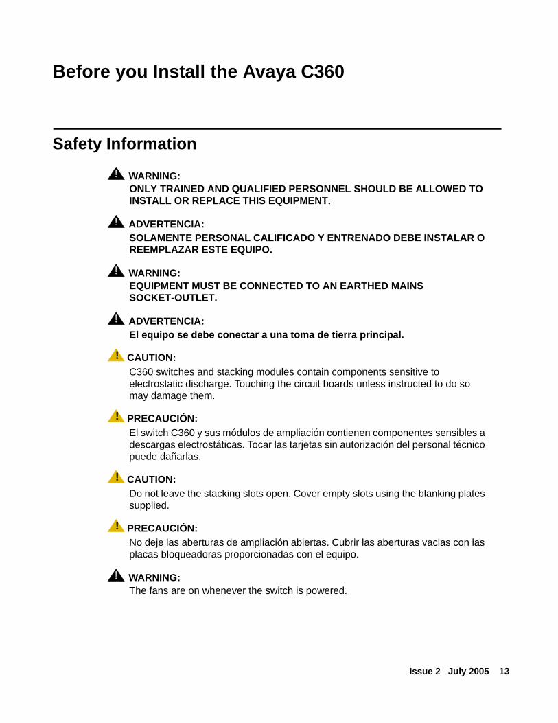
Safety Information! WARNING:
WARNING: ONLY TRAINED AND QUALIFIED PERSONNEL SHOULD BE ALLOWED TO INSTALL OR REPLACE THIS EQUIPMENT.
! ADVERTENCIA:ADVERTENCIA: SOLAMENTE PERSONAL CALIFICADO Y ENTRENADO DEBE INSTALAR O
REEMPLAZAR ESTE EQUIPO.
! WARNING:WARNING: EQUIPMENT MUST BE CONNECTED TO AN EARTHED MAINS
SOCKET-OUTLET.
! ADVERTENCIA:ADVERTENCIA: El equipo se debe conectar a una toma de tierra principal.
! CAUTION:CAUTION: C360 switches and stacking modules contain components sensitive to
electrostatic discharge. Touching the circuit boards unless instructed to do so may damage them.
! PRECAUCIÓN:PRECAUCION: El switch C360 y sus módulos de ampliación contienen componentes sensibles a
descargas electrostáticas. Tocar las tarjetas sin autorización del personal técnico puede dañarlas.
! CAUTION:CAUTION: Do not leave the stacking slots open. Cover empty slots using the blanking plates
supplied.
! PRECAUCIÓN:PRECAUCION: No deje las aberturas de ampliación abiertas. Cubrir las aberturas vacias con las
placas bloqueadoras proporcionadas con el equipo.
! WARNING:WARNING: The fans are on whenever the switch is powered.
Before you Install the Avaya C360
14 Installation and Configuration Guide Avaya C360 Multilayer Stackable Switches, version 4.5
! ADVERTENCIA:ADVERTENCIA: Los ventiladores están encendidos siempre que el equipo esté conectado
al suministro eléctrico.
Conventions Used in the DocumentationDocumentation for this product uses the following conventions to convey instructions and information:
CLI Conventions● Mandatory keywords are in the computer bold font.
● Information displayed on screen is displayed in computer font.
● Variables that you supply are in pointed brackets < >.
● Optional keywords are in square brackets [ ].
● Alternative but mandatory keywords are grouped in braces {} and separated by a vertical bar |.
● Lists of parameters from which you should choose are enclosed in square brackets [ ] and separated by a vertical bar |.
● If you enter an alphanumeric string of two words or more, enclose the string in “quotation marks”.
Conventions Used in the Documentation
Issue 2 July 2005 15
Notes, Cautions, and Warnings
! CAUTION:CAUTION: You should take care. You could do something that may damage equipment or
result in loss of data.
! PRECAUCIÓN:PRECAUCION: Debe tener cuidado. Usted podría hacer algo que puede dañar el equipo o
resultar en pérdida de datos.
! WARNING:WARNING: This means danger. Failure to follow the instructions or warnings may result in
bodily injury. You should ensure that you are qualified for this task and have read and understood all the instructions.
! ADVERTENCIA:ADVERTENCIA: Indica peligro. El no seguir las instrucciones o advertencias puede resultar
en lesión corporal. Asegúrese de estar preparado para esta tarea y de haber leído y entendido todas las instrucciones.

Before you Install the Avaya C360
16 Installation and Configuration Guide Avaya C360 Multilayer Stackable Switches, version 4.5

Issue 2 July 2005 17
Section 1: Avaya C360 Overview

18 Installation and Configuration Guide Avaya C360 Multilayer Stackable Switches, version 4.5
Issue 2 July 2005 19
Chapter 1: Avaya C360 Overview
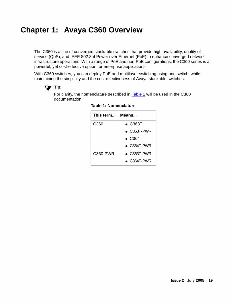
The C360 is a line of converged stackable switches that provide high availability, quality of service (QoS), and IEEE 802.3af Power over Ethernet (PoE) to enhance converged network infrastructure operations. With a range of PoE and non-PoE configurations, the C360 series is a powerful, yet cost-effective option for enterprise applications.
With C360 switches, you can deploy PoE and multilayer switching using one switch, while maintaining the simplicity and the cost effectiveness of Avaya stackable switches.
Tip:Tip: For clarity, the nomenclature described in Table 1 will be used in the C360
documentation:Table 1: Nomenclature
This term... Means...
C360 ● C363T
● C363T-PWR
● C364T
● C364T-PWR
C360-PWR ● C363T-PWR
● C364T-PWR
Avaya C360 Overview
20 Installation and Configuration Guide Avaya C360 Multilayer Stackable Switches, version 4.5
C360 Features and Benefits
Stacking● You may create logical stacks of up to ten switches that you manage and configure as a
single switch.
● Stacking is based on the Octaplane™ stacking system that provides eight Gbps stacking bandwidth to all switches in the stack.
● Each member of the stack is connected to the other members using a dedicated stacking module and cables.
● When the switches are stacked, the switches elect one switch as the master, while the other switches act as slaves. The master switch acts as the stack management agent reporting to the management system.
● Management redundancy - if the master unit fails, the remaining switches elect a new switch as the master, and the original stack configuration and IP address are maintained.
● You can add, remove and replace switches in the stack without disrupting operation.
● Auto-reconfiguration for replaced switch - the configuration of the units is distributed over the stack. When you replace a unit, you do not need to reconfigure stack-level parameters such as Spanning Tree, IP address and port redundancy.
Network Optimization● Autosensing of port speed and autonegotiation of duplex mode on all switch ports for
optimizing bandwidth.
● IEEE 802.3x flow control on all Ethernet ports.
● Auto MDI/MDI-X (cross-over cable) detection allows use of both straight and crossover cables without the need to configure ports individually.
● LAGs (Link Aggregate Group) provide enhanced fault tolerance and aggregated bandwidth of up to 800 Mbps (on 10/100BASE-T ports) or 2 Gbps (on 1000BASE-X ports).
- Ideal for high-bandwidth connections to servers, routers and switches.
- Refer to LAG (Link Aggregate Group) on page 138 for further information.
● IGMP (Internet Group Management Protocol) Snooping for limiting flooding of multicast traffic.
C360 Features and Benefits
Issue 2 July 2005 21
Manageability● SNTP (Simple Network Time Protocol) or TIME protocol for providing a consistent
timestamp to all switches from an external source. Refer to Network Time Acquiring Protocols Parameter Configuration on page 99.
● In-band management access:
- C360 Device Manager with intuitive Web-based access. Refer to C360 Device Manager on page 203 for further information.
- Up to five simultaneous Telnet connections for multiple CLI (Command Line Interface)-based sessions over the network. Refer to Establishing a Telnet Connection on page 67 for further information.
- Up to two simultaneous encrypted SSH (Secure Shell) connections for multiple CLI-based sessions over the network. Refer to Establishing an SSH Connection on page 68 for further information.
- SNMP (Simple Network Management Protocol) "get" and "set" requests (support for SNMPv1, SNMPv2 and SNMPv3). Refer to SNMP Support on page 75 for further information.
● Out-of-band management access through the switch console port to a directly attached terminal or remote terminal via a serial connection or modem. Refer to Establishing a Console Connection on page 64 and Establishing a Modem (PPP) Connection on page 73 for further information.
● Allowed managers to restrict access to a pre-defined list of IP addresses. Refer to Allowed Managers on page 86 for further information.
● Software upgrades by TFTP. Refer to Firmware Download on page 223 for further information.
● Configuration upload/download by TFTP and SCP. Refer to Uploading and Downloading Device Configurations and Images on page 101 for further information.
● "Allowed protocols" allows you to selectively enable and disable the IP protocols. Refer to Allowed Protocols on page 88 for further information.
Redundancy● IEEE 802.1w Rapid Spanning Tree Protocol (RSTP) for rapid convergence of the spanning
tree by immediately transitioning root and designated ports to the forwarding state.
- RSTP automatically detects switches that are configured as 802.1w Rapid Spanning Tree or 802.1D Spanning Tree and operates accordingly. Refer to Spanning Tree Protocol on page 131 for further information.
Avaya C360 Overview
22 Installation and Configuration Guide Avaya C360 Multilayer Stackable Switches, version 4.5
- Edge port for eliminating the forwarding delay by enabling a port to immediately transition from the blocking state to the forwarding state.
● Port redundancy provides a backup for important links. If one link fails, the backup link takes over, preventing disruption to network traffic. Refer to Port Redundancy on page 140 for further information.
● Inter-module redundancy is hardware-based and intended for important links that need to be maintained even if there are changes in the stack. Refer to Intermodule Port Redundancy on page 141 for further information.
● Port redundancy combined with 802.1w provides configuration flexibility in complex network configurations.
● LAG redundancy adds the reliability of port redundancy to LAGs, thus providing inter-port as well as intra-port redundancy.
● Stack redundancy - in the unlikely event that a C360 switch or Octaplane link should fail, stack integrity is maintained if the redundant cable is connected to the stack. The broken link is bypassed and data transmission continues uninterrupted.
● BUPS (Backup Power Supply) - you can connect an additional DC power supply to the BUPS connectors to ensure no disruption if the internal PSU fails. Refer to Connecting a BUPS on page 55 for further information.
VLAN Support● Support for up to 3,071 VLANs (in the range of 1-3071) according to the IEEE 802.1Q
standard for assigning VLANs associated with appropriate network resources, traffic patterns, and bandwidth. Refer to VLANs on page 120 for further information.
● IEEE 802.1Q lets a VLAN span multiple switches. This provides management and control of broadcast and multicast traffic and network security as well as all the other benefits of VLANs over the entire network.
● PVID - VLAN-per-port for maximum flexibility and security.
● Multi VLAN binding (Multiple VLANs per port) allows access to shared resources by stations that belong to different VLANs through the same port. Refer to Multi VLAN Binding on page 122 for further information.
● Ingress VLAN security accepts or rejects packets depending on their tagging and the VLAN binding mode on the port. Refer to Ingress VLAN Security on page 123 for further information.
C360 Features and Benefits
Issue 2 July 2005 23
Security● Password-protected access - three levels (read-only, read-write, and supervisor access) to
management interfaces for protection against unauthorized configuration changes. Refer to Security Levels on page 62 for further information.
● Access Control allows you to define which packets have access - based on the source or destination address information in the packet or on other information in Layer 3 and Layer 4 (on routed packets only). Refer to Policy Configuration on page 190 for further information.
● IEEE 802.1x port-based authentication to prevent unauthorized devices (clients) from gaining access to the network. Refer to IEEE 802.1x (Port Based Network Access Control) on page 126 for further information.
● 802.1x with attribute assignments allows you to set VLAN ID, priority or multi-vlan binding per user. Refer to IEEE 802.1x (Port Based Network Access Control) on page 126 for further information.
● Remote Authentication Dial-In User Service (RADIUS) provides flexible administrative control over authentication and authorization processes. Refer to RADIUS on page 82 for further information.
● SNMP v3 adds security features to the SNMP v1 and SNMP v2c feature set. Refer to SNMPv3 on page 77 for further information.
● SSH enables establishing a remote session over a secured tunnel, also called a remote shell. Refer to Establishing an SSH Connection on page 68 for further information.
● MAC Security is intended to filter incoming frames (from the line) with an unauthorized source MAC address (SA). Refer to MAC Security on page 136 for further information.
Quality of Service (QoS) ● Per-port 802.1p marking for untagged traffic ensures that time-sensitive packets receive
the appropriate priority. Refer to Priority on page 116 for further information.
● Four egress queues on all switch ports.
- You can configure these queues with either the WRR (Weighted Round Robin) scheduling algorithm or the strict priority scheduling algorithm.
● 802.1p and DSCP mapping. Refer to Policy Configuration Overview on page 190 for further information.
● Classification of traffic per L3/L4 attributes on routed traffic only (classification based on information in the IP and TCP/UDP headers)
● 802.1p QoS marking based on packet classification for high-performance quality of service at the network edge, allowing for differentiated service levels for different types of network
Avaya C360 Overview
24 Installation and Configuration Guide Avaya C360 Multilayer Stackable Switches, version 4.5
traffic and for prioritizing mission-critical traffic in the network. This applies to routed traffic only.
Monitoring● Front panel LEDs that provide at-a-glance port and switch status. Refer to Avaya C360
Front and Rear Panels on page 31 for further information.
● Port mirroring lets you transparently mirror traffic from one source port to a destination port to monitor traffic. Refer to Port Mirroring on page 151 for further information.
● Four groups (history, statistics, alarms, and events) of embedded remote monitoring (RMON) agents for network monitoring and traffic analysis. Refer to RMON on page 147 for further information.
● Syslog facility for logging system messages about events, errors and other important information. Refer to System Logging on page 106 for further information.
● Port classification to regular/valuable so in case of link failure notification is generated for valuable ports only. Refer to Port Classification on page 143 for further information.
● The C360 supports SMON switch monitoring which provides unprecedented top-down monitoring of switched network traffic at the following levels:
- Enterprise Monitoring
- Device Monitoring
- VLAN Monitoring
- Port-level Monitoring
This top-down approach gives you rapid troubleshooting and performance trending to keep the network running optimally. Refer to SMON on page 149 for further information.
Power over Ethernet (PoE) Support on C360-PWR switches● 802.3af support for PoE standard based to provide power to IP phones, wireless access
point and other standard based end points. Refer to VLANs on page 120 for further information.
● Autodetection and control of inline phone power on a per-port basis on all 10/100 ports for plug-and-play configuration. Refer to How the C360-PWR Switches Detect a Powered Device on page 198 for further information.
● Priority-based power management ensures that key devices, such as IP telephones, receive power.
● Up to 15.4W per powered device
C360 Features and Benefits
Issue 2 July 2005 25
● The C360-PWR switches can provide PoE on all 10/100BASE-T ports.
Layer 3 Support● Hardware-based Layer 3 switching for high performance.
● VRRP (Virtual Router Redundancy Protocol) for Layer 3 router redundancy. The Virtual Router Redundancy Protocol (VRRP) eliminates the single point of failure inherent in the static default routed environment. Refer to VRRP (Virtual Router Redundancy Protocol) Configuration on page 186 for further information.
● IP routing protocols for load balancing and for constructing scalable, routed backbones:
- Routing Information Protocol (RIP) versions 1 and 2. Refer to RIP (Routing Interchange Protocol) Configuration on page 172 for further information.
- Open Shortest Path First (OSPF). Refer to OSPF (Open Shortest Path First) Configuration on page 175 for further information.
● IP routing between VLANs (inter-VLAN routing) for full Layer 3 switching between two or more VLANs, allowing each VLAN to maintain its own autonomous data-link domain
● Address Resolution Protocol (ARP) for identifying a switch through its IP address and its corresponding Media Access Control (MAC) address. Refer to ARP (Address Resolution Protocol) Table Configuration on page 181 for further information.
● NetBIOS Re-broadcast for applications such as WINS that use broadcast but may need to communicate with stations on other subnets or VLANs. Refer to NetBIOS Re-broadcast Configuration on page 185 for further information.
● Static IP routing for manually building a routing table of network path information. Refer to Static Routing Configuration on page 177 for further information.
● ECMP (equal-cost routing) provides load balancing and redundancy by splitting traffic among several equivalent paths.
● Internet Control Message Protocol (ICMP) and ICMP Router Discovery Protocol (IRDP) are used by routers to notify the hosts on the data link that a better route is available for a particular destination.
● DHCP/ BootP relay for forwarding UDP broadcasts, including IP address requests, from DHCP/BootP clients. Refer to BOOTP/DHCP (Dynamic Host Configuration Protocol) Relay Configuration on page 183 for further information.
ManagementThe C360 switch is designed for plug-and-play operation: you need to configure only basic IP information for the switch and connect it to the other devices in your network. If you have
Avaya C360 Overview
26 Installation and Configuration Guide Avaya C360 Multilayer Stackable Switches, version 4.5
specific network needs, you can configure and monitor the switch - individually or as part of a stack - through its various management interfaces.
Management Interface Options
You can configure and monitor individual switches and the entire stack by using these interfaces:
● The built-in C360 Device Manager allows you to configure and manage a C360 stack using a Web browser without purchasing additional software.
This application works with the Microsoft Internet Explorer and Netscape Navigator web browsers and Sun Microsystems Java Plug-in.
● CLI - You can configure and monitor the switch or the stack from the CLI. You can access the CLI either by connecting your management station directly to the switch console port or by using Telnet, PPP or SSH from a remote management station.
● SNMP - provides a means to monitor and control the switch or the stack. You can manage switch configuration settings, performance, security, and collect statistics by using SNMP management applications such Avaya Integrated Management and HP OpenView.
● You can manage the switch from an SNMP-compatible management station that is running platform such as HP OpenView. The switch supports a comprehensive set of MIB extensions and four RMON groups.
● Avaya IM (Integrated Management) network management provides further control and allows you to manage other Avaya equipment in your network. It provides the ease-of-use and features necessary for optimal network utilization.
- Integrated Management is available for Microsoft Windows 2000, XP, and 2003 and Solaris 2.8.
- Integrated Management can operate in standalone mode with Microsoft Windows 2000, XP, and 2003 and Solaris 2.8.
- Integrated Management operates under HP OpenView for Microsoft Windows 2000, XP, and 2003.
C360 Switch Configurations
Issue 2 July 2005 27
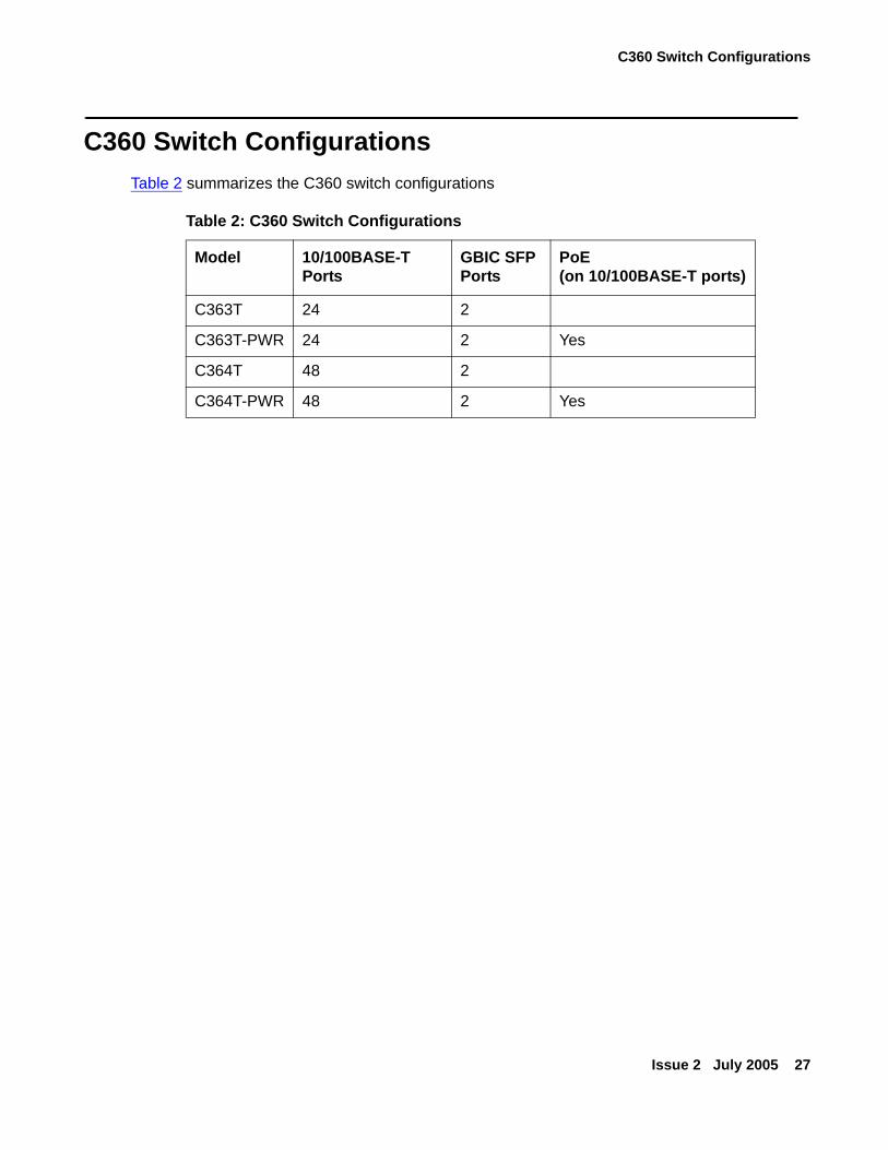
C360 Switch ConfigurationsTable 2 summarizes the C360 switch configurations
Table 2: C360 Switch Configurations
Model 10/100BASE-T Ports
GBIC SFP Ports
PoE (on 10/100BASE-T ports)
C363T 24 2
C363T-PWR 24 2 Yes
C364T 48 2
C364T-PWR 48 2 Yes

Avaya C360 Overview
28 Installation and Configuration Guide Avaya C360 Multilayer Stackable Switches, version 4.5

Issue 2 July 2005 29
Section 2: Installing the C360

30 Installation and Configuration Guide Avaya C360 Multilayer Stackable Switches, version 4.5

Issue 2 July 2005 31
Chapter 2: Avaya C360 Front and Rear Panels
This chapter describes the front and rear panels of the C360 switches, including the LEDs, buttons and power inlets:
● C360 Front Panels
● C360 Rear Panel
Avaya C360 Front and Rear Panels
32 Installation and Configuration Guide Avaya C360 Multilayer Stackable Switches, version 4.5
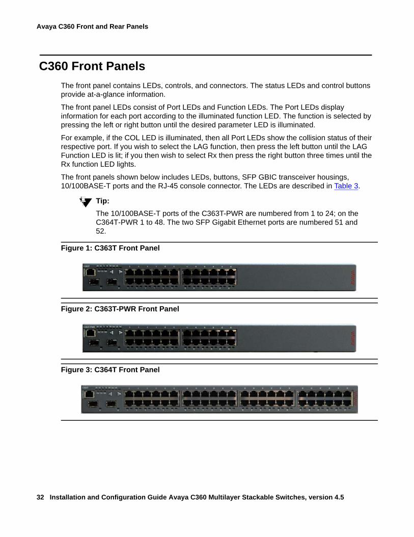
C360 Front PanelsThe front panel contains LEDs, controls, and connectors. The status LEDs and control buttons provide at-a-glance information.
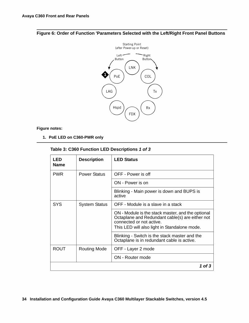
The front panel LEDs consist of Port LEDs and Function LEDs. The Port LEDs display information for each port according to the illuminated function LED. The function is selected by pressing the left or right button until the desired parameter LED is illuminated.
For example, if the COL LED is illuminated, then all Port LEDs show the collision status of their respective port. If you wish to select the LAG function, then press the left button until the LAG Function LED is lit; if you then wish to select Rx then press the right button three times until the Rx function LED lights.
The front panels shown below includes LEDs, buttons, SFP GBIC transceiver housings, 10/100BASE-T ports and the RJ-45 console connector. The LEDs are described in Table 3.
Tip:Tip: The 10/100BASE-T ports of the C363T-PWR are numbered from 1 to 24; on the
C364T-PWR 1 to 48. The two SFP Gigabit Ethernet ports are numbered 51 and 52.
Figure 1: C363T Front Panel
Figure 2: C363T-PWR Front Panel
Figure 3: C364T Front Panel
C360 Front Panels
Issue 2 July 2005 33
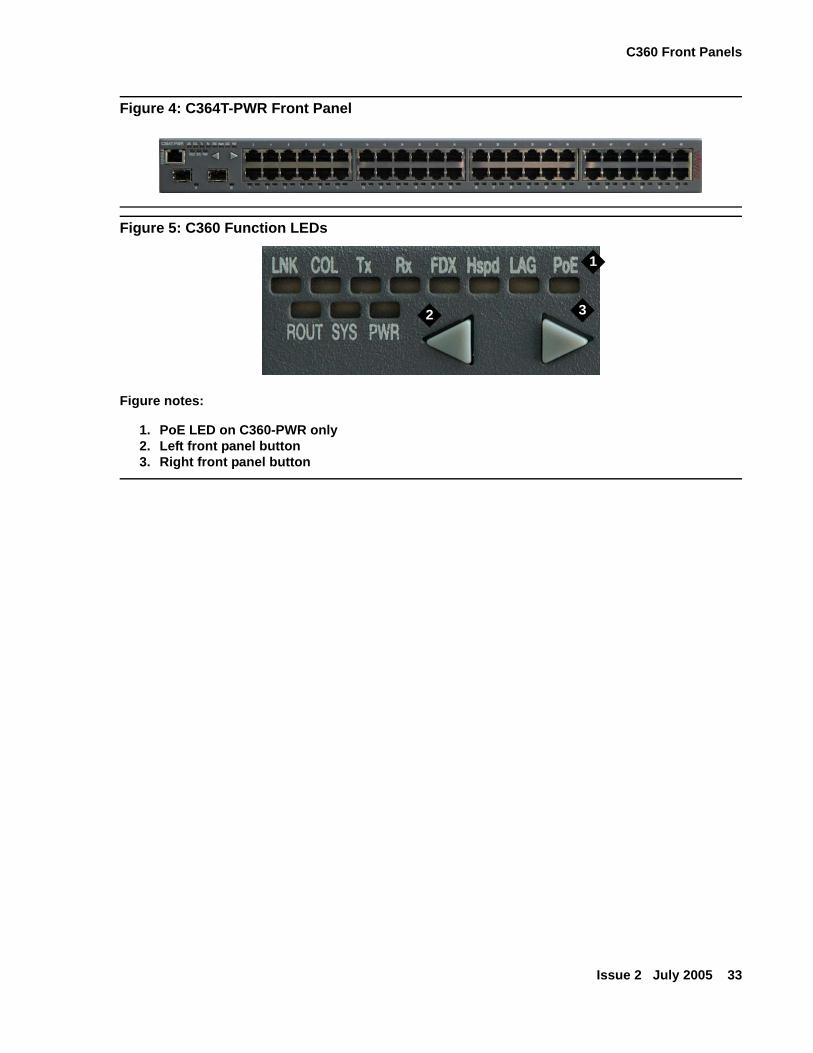
Figure 4: C364T-PWR Front Panel
Figure 5: C360 Function LEDs
Figure notes:
1. PoE LED on C360-PWR only2. Left front panel button3. Right front panel button
1
2 3
Avaya C360 Front and Rear Panels
34 Installation and Configuration Guide Avaya C360 Multilayer Stackable Switches, version 4.5
Figure 6: Order of Function 'Parameters Selected with the Left/Right Front Panel Buttons
Figure notes:
1. PoE LED on C360-PWR only
Table 3: C360 Function LED Descriptions 1 of 3
LED Name
Description LED Status
PWR Power Status OFF - Power is off
ON - Power is on
Blinking - Main power is down and BUPS is active
SYS System Status OFF - Module is a slave in a stack
ON - Module is the stack master, and the optional Octaplane and Redundant cable(s) are either not connected or not active.This LED will also light in Standalone mode.
Blinking - Switch is the stack master and the Octaplane is in redundant cable is active.
ROUT Routing Mode OFF - Layer 2 mode
ON - Router mode
1 of 3
LeftButton
RightButton
Starting Point (after Power-up or Reset)
COL
Tx
Rx
FDX
Hspd
LAG
PoE
LNK
1
C360 Front Panels
Issue 2 July 2005 35
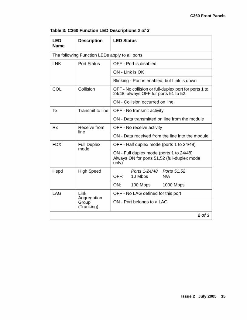
The following Function LEDs apply to all ports
LNK Port Status OFF - Port is disabled
ON - Link is OK
Blinking - Port is enabled, but Link is down
COL Collision OFF - No collision or full-duplex port for ports 1 to 24/48; always OFF for ports 51 to 52.
ON - Collision occurred on line.
Tx Transmit to line OFF - No transmit activity
ON - Data transmitted on line from the module
Rx Receive from line
OFF - No receive activity
ON - Data received from the line into the module
FDX Full Duplex mode
OFF - Half duplex mode (ports 1 to 24/48)
ON - Full duplex mode (ports 1 to 24/48)Always ON for ports 51,52 (full-duplex mode only)
Hspd High Speed Ports 1-24/48 Ports 51,52OFF: 10 Mbps N/A
ON: 100 Mbps 1000 Mbps
LAG Link Aggregation Group (Trunking)
OFF - No LAG defined for this port
ON - Port belongs to a LAG
Table 3: C360 Function LED Descriptions 2 of 3
LED Name
Description LED Status
2 of 3
Avaya C360 Front and Rear Panels
36 Installation and Configuration Guide Avaya C360 Multilayer Stackable Switches, version 4.5
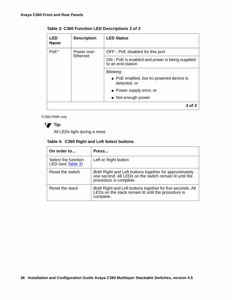
*C360-PWR only
Tip:Tip: All LEDs light during a reset.
PoE* Power over Ethernet.
OFF - PoE disabled for this port
ON - PoE is enabled and power is being supplied to an end-station
Blinking:● PoE enabled, but no powered device is
detected, or
● Power supply error, or
● Not enough power
Table 4: C360 Right and Left Select buttons
On order to... Press...
Select the function LED (see Table 3)
Left or Right button
Reset the switch Both Right and Left buttons together for approximately one second. All LEDs on the switch remain lit until the procedure is complete.
Reset the stack Both Right and Left buttons together for five seconds. All LEDs on the stack remain lit until the procedure is complete.
Table 3: C360 Function LED Descriptions 3 of 3
LED Name
Description LED Status
3 of 3
C360 Rear Panel
Issue 2 July 2005 37
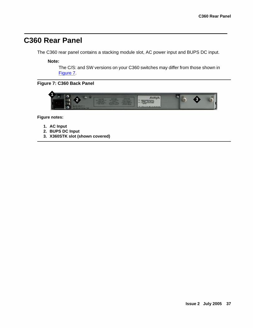
C360 Rear PanelThe C360 rear panel contains a stacking module slot, AC power input and BUPS DC input.
Note:Note: The C/S: and SW versions on your C360 switches may differ from those shown in
Figure 7.
Figure 7: C360 Back Panel
Figure notes:
1. AC Input2. BUPS DC Input3. X360STK slot (shown covered)
12 3

Avaya C360 Front and Rear Panels
38 Installation and Configuration Guide Avaya C360 Multilayer Stackable Switches, version 4.5
Issue 2 July 2005 39
Chapter 3: Installation
The C360 switch is ready to work after you complete the installation instructions described in this chapter. After you have completed the procedures in this chapter, proceed to Chapter 4: Powering Up the Avaya C360
The following steps are described in this chapter:
● Preparing Needed Tools
● Site Preparation
● Rack Mounting (Optional)
● Wall Mounting (Optional)
● Stacking (optional)
● Making Connections to Network Equipment
● Installing SFP GBIC Transceivers
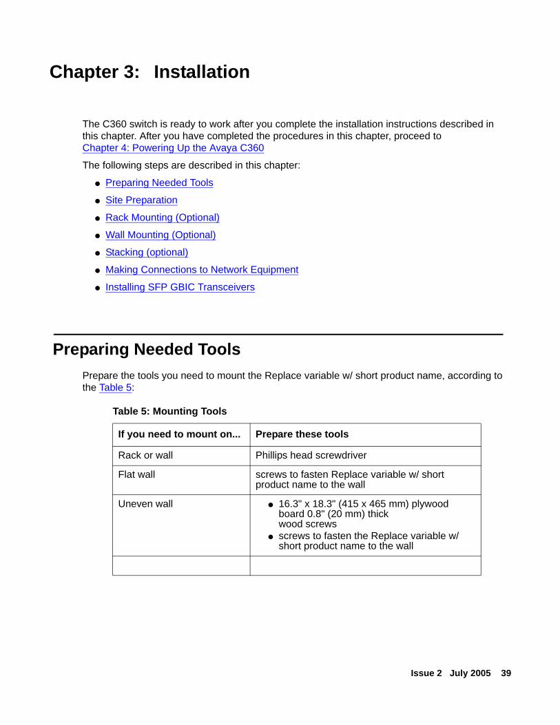
Preparing Needed ToolsPrepare the tools you need to mount the Replace variable w/ short product name, according to the Table 5:
Table 5: Mounting Tools
If you need to mount on... Prepare these tools
Rack or wall Phillips head screwdriver
Flat wall screws to fasten Replace variable w/ short product name to the wall
Uneven wall ● 16.3" x 18.3" (415 x 465 mm) plywood board 0.8" (20 mm) thickwood screws
● screws to fasten the Replace variable w/ short product name to the wall
Installation
40 Installation and Configuration Guide Avaya C360 Multilayer Stackable Switches, version 4.5
Site PreparationYou can mount the C360 alone or in a stack in a standard 19-inch equipment rack located in a wiring closet or equipment room. You can build a logical stack of up to ten C360 switches.
Ensure that the location where you install your Replace variable w/ short product name fulfills the following requirements:
● Cables are away from sources of electrical noise such as:
● radio transmitters
● broadcast amplifiers
● power lines
● fluorescent light fixtures
● Water or moisture cannot enter the chassis.
● Air can flow freely around all sides of the chassis.
● The vents on the sides of the chassis are not blocked.
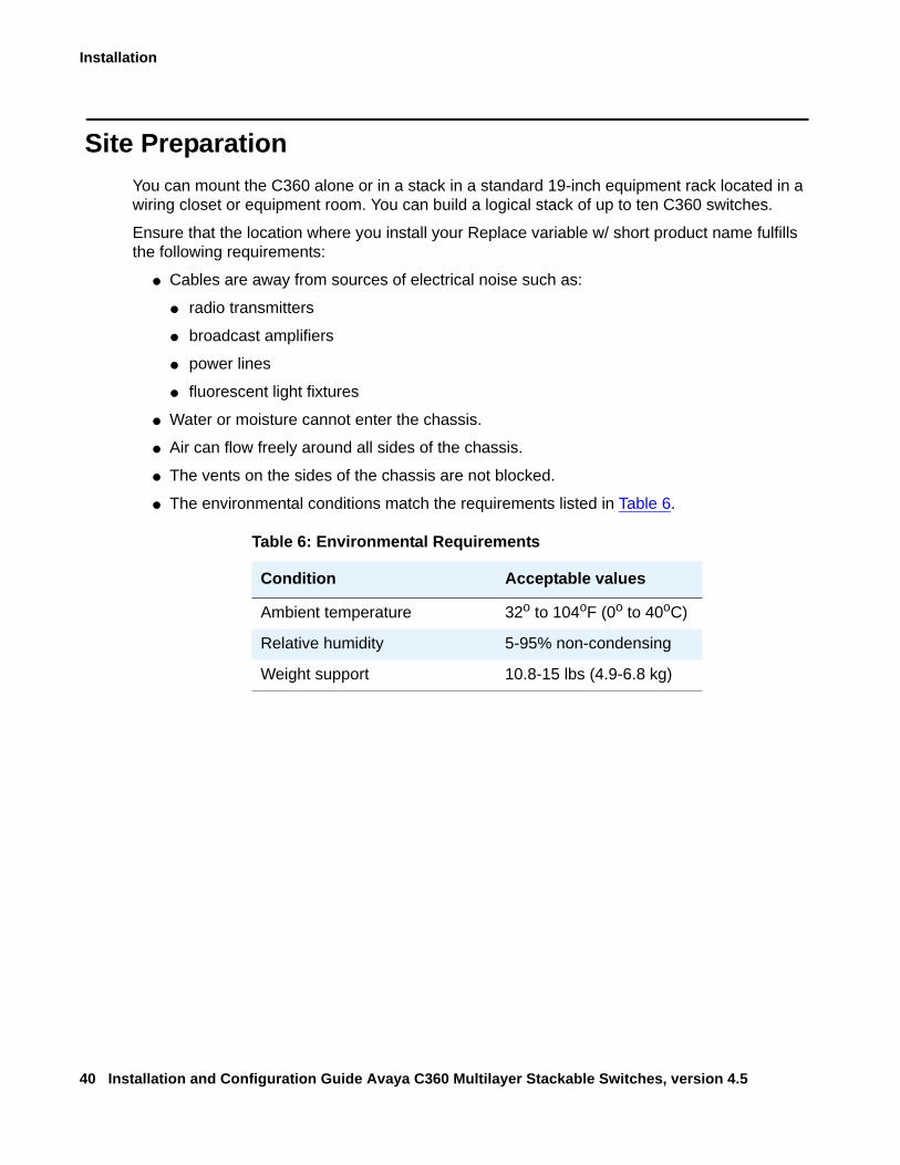
● The environmental conditions match the requirements listed in Table 6.
Table 6: Environmental Requirements
Condition Acceptable values
Ambient temperature 32o to 104oF (0o to 40oC)
Relative humidity 5-95% non-condensing
Weight support 10.8-15 lbs (4.9-6.8 kg)
Site Preparation
Issue 2 July 2005 41
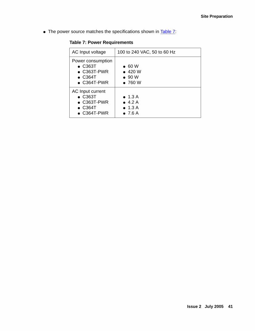
● The power source matches the specifications shown in Table 7:
Table 7: Power Requirements
AC Input voltage 100 to 240 VAC, 50 to 60 Hz
Power consumption● C363T● C363T-PWR● C364T● C364T-PWR
● 60 W● 420 W● 90 W● 760 W
AC Input current● C363T● C363T-PWR● C364T● C364T-PWR
● 1.3 A● 4.2 A● 1.3 A● 7.6 A
Installation
42 Installation and Configuration Guide Avaya C360 Multilayer Stackable Switches, version 4.5
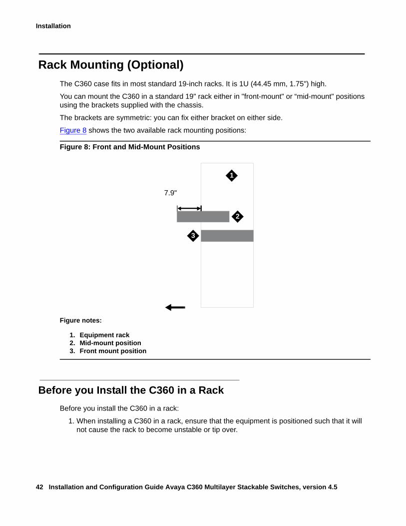
Rack Mounting (Optional)The C360 case fits in most standard 19-inch racks. It is 1U (44.45 mm, 1.75") high.
You can mount the C360 in a standard 19" rack either in "front-mount" or “mid-mount" positions using the brackets supplied with the chassis.
The brackets are symmetric: you can fix either bracket on either side.
Figure 8 shows the two available rack mounting positions:
Figure 8: Front and Mid-Mount Positions
Before you Install the C360 in a RackBefore you install the C360 in a rack:
1. When installing a C360 in a rack, ensure that the equipment is positioned such that it will not cause the rack to become unstable or tip over.
Figure notes:
1. Equipment rack2. Mid-mount position3. Front mount position
7.9"
1
2
3
Rack Mounting (Optional)
Issue 2 July 2005 43
2. Ensure that the combination of equipment in the rack will not cause an overload or overcurrent condition on the power strip being used and/or the customer's branch circuit.
3. A C360 switch weighs a maximum of 15 pounds (6.8 kg). Be careful when installing or removing the C360 switch from the rack.
4. If a power strip is being used in the rack, ensure that it has a reliable earth connection. If the C360 equipment will be plugged directly into a wall outlet, ensure that there is a reliable ground connection at the outlet.
5. Ensure that the internal rack ambient temperature is within the operating specification limits of the C360.
6. Ventilation for the C360 is from side to side. Ensure that there is adequate space on each side of the C360 equipment when installed in the rack to allow sufficient airflow.
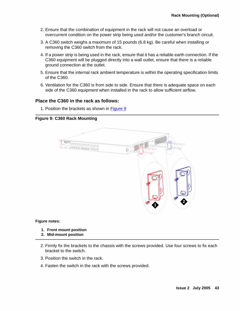
Place the C360 in the rack as follows:1. Position the brackets as shown in Figure 9
Figure 9: C360 Rack Mounting
2. Firmly fix the brackets to the chassis with the screws provided. Use four screws to fix each bracket to the switch.
3. Position the switch in the rack.
4. Fasten the switch in the rack with the screws provided.
Figure notes:
1. Front mount position2. Mid-mount position
C363TIn
12
Installation
44 Installation and Configuration Guide Avaya C360 Multilayer Stackable Switches, version 4.5
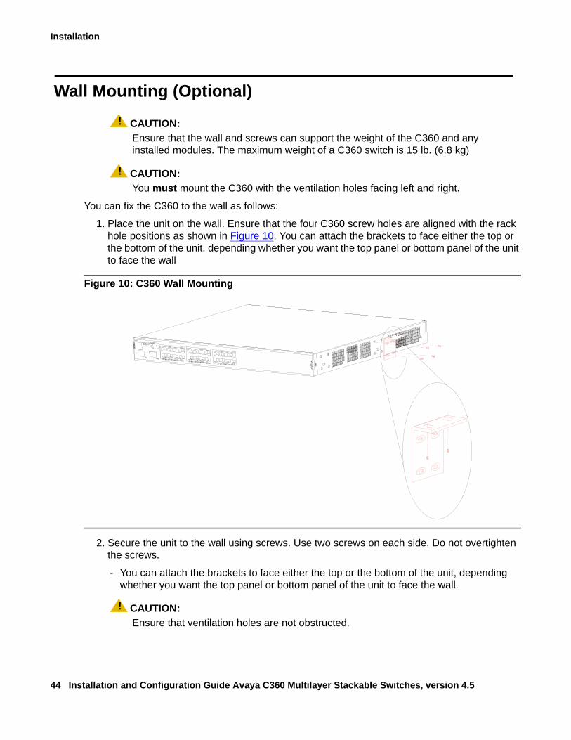
Wall Mounting (Optional)! CAUTION:
CAUTION: Ensure that the wall and screws can support the weight of the C360 and any installed modules. The maximum weight of a C360 switch is 15 lb. (6.8 kg)
! CAUTION:CAUTION: You must mount the C360 with the ventilation holes facing left and right.
You can fix the C360 to the wall as follows:
1. Place the unit on the wall. Ensure that the four C360 screw holes are aligned with the rack hole positions as shown in Figure 10. You can attach the brackets to face either the top or the bottom of the unit, depending whether you want the top panel or bottom panel of the unit to face the wall
Figure 10: C360 Wall Mounting
2. Secure the unit to the wall using screws. Use two screws on each side. Do not overtighten the screws.
- You can attach the brackets to face either the top or the bottom of the unit, depending whether you want the top panel or bottom panel of the unit to face the wall.
! CAUTION:CAUTION: Ensure that ventilation holes are not obstructed.
Stacking (optional)
Issue 2 July 2005 45
Stacking (optional)
There are two main steps for creating stacks:1. Installing the X360STK Stacking Module
2. Inter-Connecting Switches
Installing the X360STK Stacking Module
! CAUTION:CAUTION: C360 switches and stacking modules contain components sensitive to
electrostatic discharge. Touching the circuit boards unless instructed to do so may damage them.
! PRECAUCIÓN:PRECAUCION: El switch C360 y sus módulos de ampliación contienen componentes sensibles a
descargas electrostáticas. Tocar las tarjetas sin autorización del personal técnico puede dañarlas.
! CAUTION:CAUTION: Do not leave the stacking slots open. Cover empty slots using the blanking plates
supplied.
! PRECAUCIÓN:PRECAUCION: No deje las aberturas de ampliación abiertas. Cubrir las aberturas vacias con las
placas bloqueadoras proporcionadas con el equipo.
To install the stacking module in the C360:
1. Remove the existing stacking module or blanking plate from the back of the C360 switch.
2. Insert the stacking module gently into the slot, ensuring that the PCB (printed circuit board) is aligned with the guide rails.
3. Press the module in firmly until it is completely inserted into the Avaya C360.
Note:Note: Ensure that the screws on the module are properly aligned with the holes in the
chassis before tightening them.
4. Tighten the two screws on the side panel of the stacking module by turning the knurled knobs clockwise.
Installation
46 Installation and Configuration Guide Avaya C360 Multilayer Stackable Switches, version 4.5
Inter-Connecting Switches
Tip:Tip: You may stack the C360 with the G700, P333T-PWR, P332G-ML or P332GT-ML.
Please refer to Appendix A: Mixed Stacks for further information on mixed stacks.
Note:Note: The two ends of the Octaplane cable terminate with different connectors. Each
connector can only be connected to its matching port.
The following cables are used to connect stacked switches:
● Short Octaplane cable (X330SC) - ivory-colored, used to connect adjacent switches (Catalog No. CB0223) or switches separated by a BUPS unit. This cable is 30 cm. long.
● Long/Extra Long Octaplane cable (X330LC/X330L-LC) - ivory-colored, used to connect switches from two different physical stacks, or switches separated by a BUPS unit (Catalog No. CB0225/CB0270). The long cable is 2 m long; the extra-long cable is 8 m long.
● Redundant/Long Redundant Octaplane cable (X330RC/X330L-RC) - black, used to connect the top and bottom switches of a stack (Catalog No. CB0222/CB0269). This cable is 2 m long.
Tip:Tip: You may use the same cables with P330 and P330-ML switches.
To connect stacked switches:
Tip:Tip: When adding a switch to an existing stack, first connect the stacking cables and
then power up the module.
To connect stacked switches:
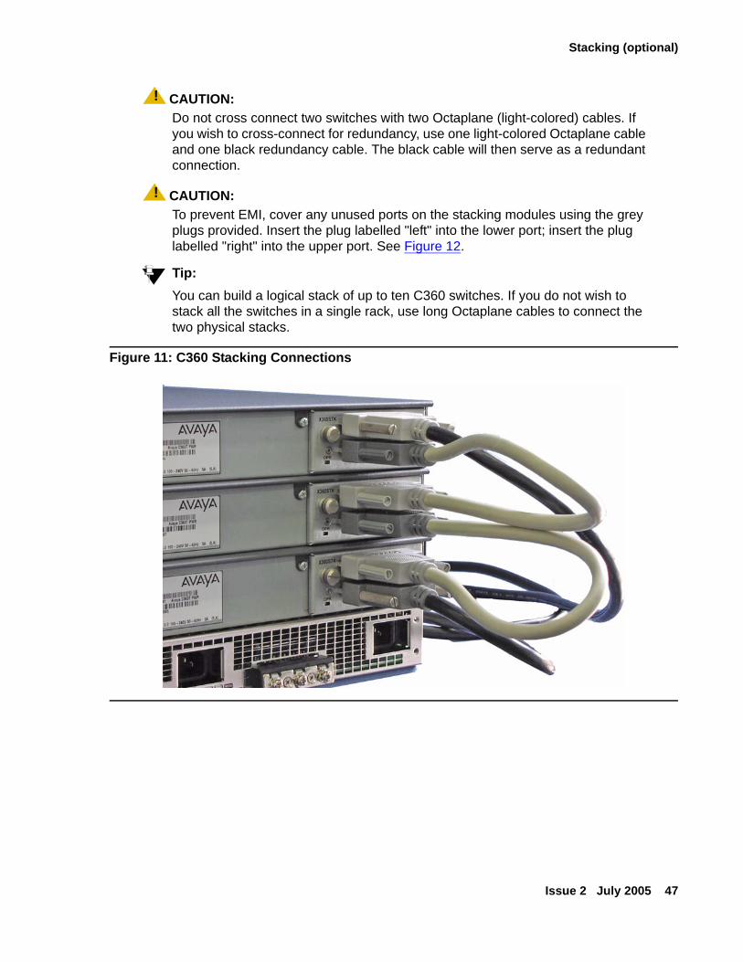
1. Plug the light grey connector of the Short Octaplane cable into the port marked “to upper unit" of the bottom C360 switch.
2. Plug dark grey connector of same Short Octaplane cable to the port marked “to lower unit" in the unit above. The connections are illustrated in Figure 11.
3. Repeat Step 1and Step 2 until you reach the top switch in the stack.
4. If you wish to implement stack redundancy, use the Redundant Cable to connect the port marked “to lower unit" on the bottom switch to the port marked “to upper unit"" on the top switch of the stack.
5. Power up the added modules.
Stacking (optional)
Issue 2 July 2005 47
! CAUTION:CAUTION: Do not cross connect two switches with two Octaplane (light-colored) cables. If
you wish to cross-connect for redundancy, use one light-colored Octaplane cable and one black redundancy cable. The black cable will then serve as a redundant connection.
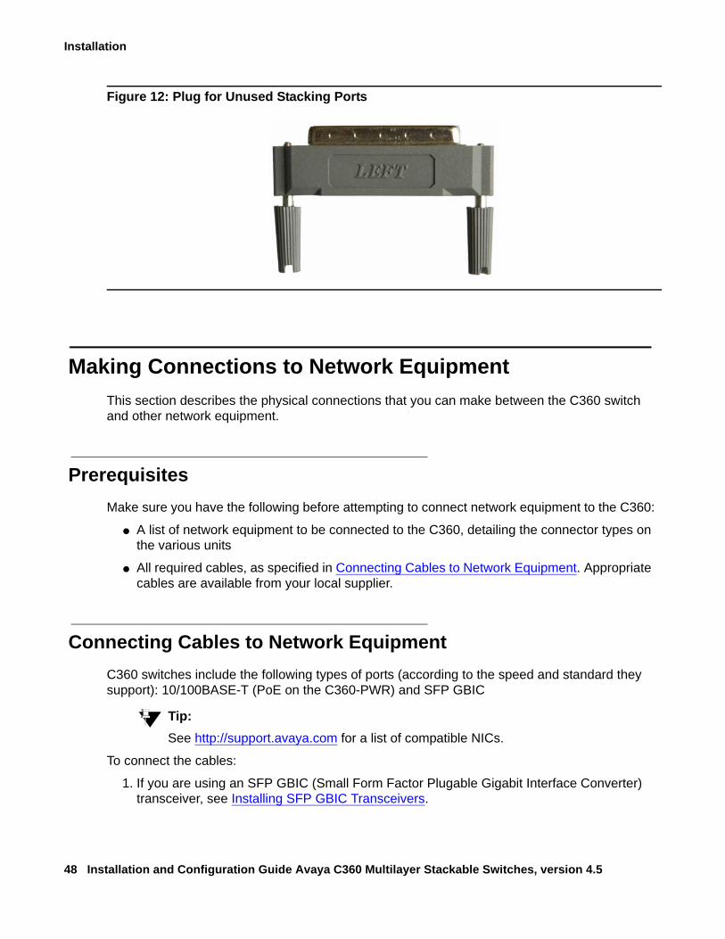
! CAUTION:CAUTION: To prevent EMI, cover any unused ports on the stacking modules using the grey
plugs provided. Insert the plug labelled "left" into the lower port; insert the plug labelled "right" into the upper port. See Figure 12.
Tip:Tip: You can build a logical stack of up to ten C360 switches. If you do not wish to
stack all the switches in a single rack, use long Octaplane cables to connect the two physical stacks.
Figure 11: C360 Stacking Connections
Installation
48 Installation and Configuration Guide Avaya C360 Multilayer Stackable Switches, version 4.5
Figure 12: Plug for Unused Stacking Ports
Making Connections to Network EquipmentThis section describes the physical connections that you can make between the C360 switch and other network equipment.
PrerequisitesMake sure you have the following before attempting to connect network equipment to the C360:
● A list of network equipment to be connected to the C360, detailing the connector types on the various units
● All required cables, as specified in Connecting Cables to Network Equipment. Appropriate cables are available from your local supplier.
Connecting Cables to Network EquipmentC360 switches include the following types of ports (according to the speed and standard they support): 10/100BASE-T (PoE on the C360-PWR) and SFP GBIC
Tip:Tip: See http://support.avaya.com for a list of compatible NICs.
To connect the cables:
1. If you are using an SFP GBIC (Small Form Factor Plugable Gigabit Interface Converter) transceiver, see Installing SFP GBIC Transceivers.
Installing SFP GBIC Transceivers
Issue 2 July 2005 49
2. For all other ports, connect an Ethernet copper cable (not supplied) directly to the ports. The copper ports can operate with 2 pair (4 wire) or 4 pair (8 wire) CAT 5 Ethernet cables (crossed or straight). The maximum cable length is 100 m (328 ft.).
3. Connect the other end of the cable to the Ethernet port of the PC, server, router, workstation, switch, hub, or other end device.
4. Check that the appropriate link (LNK) LED lights up.
Installing SFP GBIC TransceiversThe SFP GBIC (Gigabit Interface Converter) have been tested for use with the C360 Gigabit Ethernet ports. For a list of approved SFP GBIC transceivers, see: http://support.avaya.com
SFP GBIC transceivers are hot-swappable.
Safety Information
! CAUTION:CAUTION: You must operate the SFP GBIC transceivers under recommended operating
conditions, as specified for each transceiver.
! WARNING:WARNING: The use of optical instruments with this product will increase eye hazard.
! ADVERTENCIA:ADVERTENCIA: El uso de instrumentos ópticos en este producto aumentará el riesgo de peligro
para la vista.
Usage Restriction
When a SFP GBIC transceiver is inserted in the module but is not in use, protect the Tx and Rx ports with an optical connector or a dust plug.
! CAUTION:CAUTION: Use only approved SFP GBIC transceivers. All approved SFP GBIC transceivers:
1) are 3.3V. Do not insert a 5VSFP GBIC. 2) use Serial Identification. Do not use a GBIC that utilizes Parallel Identification.
Installation
50 Installation and Configuration Guide Avaya C360 Multilayer Stackable Switches, version 4.5
Installing and Removing a SFP GBIC TransceiverThe SFP GBIC transceiver is fastened using a snap-in clip.
To install the SFP GBIC transceiver:
● Insert the transceiver (take care to insert it the right way up) until it clicks in place.
● Refer to Copper GBIC Transceiver Installation Notes on page 51 if you are installing a copper GBIC transceiver.
To remove the SFP GBIC transceiver:
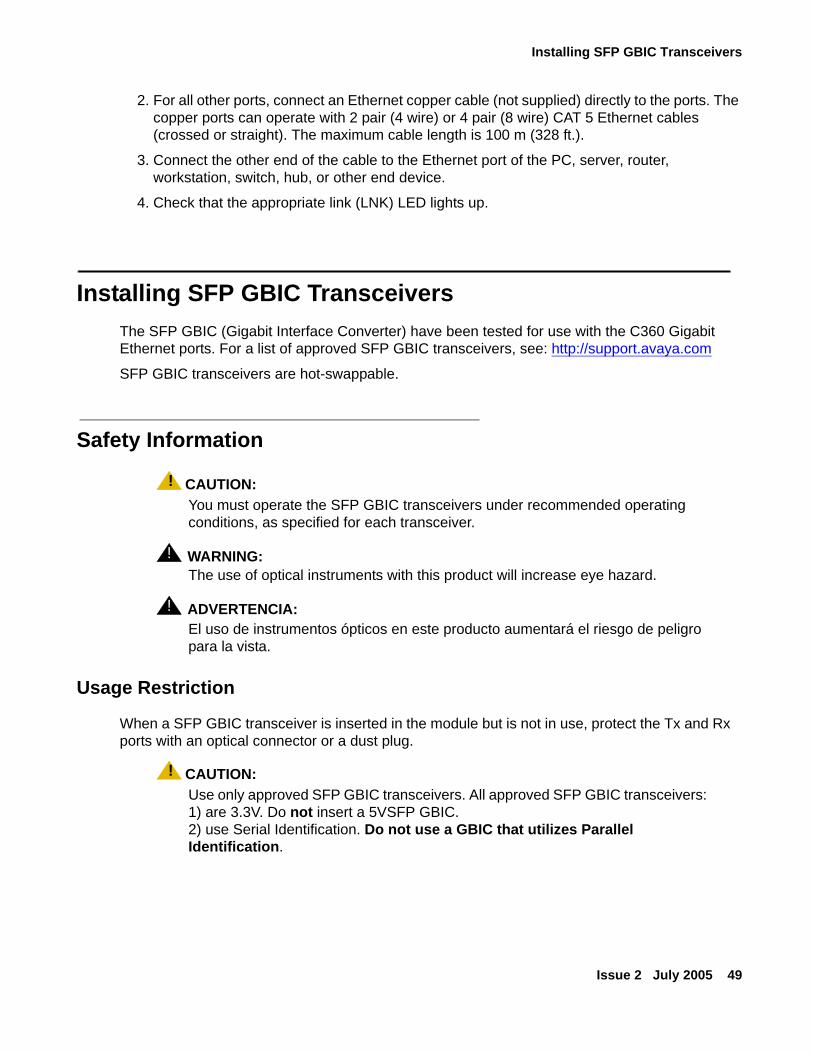
1. Press the clip on the base of the transceiver see Figure 13 for the location.
Figure 13: Clip Location on Base of Transceiver.
2. Pull the transceiver out.
Figure notes:
1. Transceiver clip location
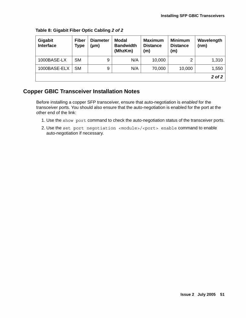
Table 8: Gigabit Fiber Optic Cabling 1 of 2
Gigabit Interface
FiberType
Diameter (µm)
Modal Bandwidth (MhzKm)
Maximum Distance (m)
Minimum Distance (m)
Wavelength (nm)
1000BASE-SX MM 62.5 160 220 2 850
1000BASE-SX MM 62.5 200 275 2 850
1000BASE-SX MM 50 400 500 2 850
1000BASE-SX MM 50 500 550 2 850
1000BASE-LX MM 62.5 500 550 2 1,310
1000BASE-LX MM 50 400 550 2 1,310
1 of 2
1
Installing SFP GBIC Transceivers
Issue 2 July 2005 51
Copper GBIC Transceiver Installation Notes
Before installing a copper SFP transceiver, ensure that auto-negotiation is enabled for the transceiver ports. You should also ensure that the auto-negotiation is enabled for the port at the other end of the link:
1. Use the show port command to check the auto-negotiation status of the transceiver ports.
2. Use the set port negotiation <module>/<port> enable command to enable auto-negotiation if necessary.
1000BASE-LX SM 9 N/A 10,000 2 1,310
1000BASE-ELX SM 9 N/A 70,000 10,000 1,550
Table 8: Gigabit Fiber Optic Cabling 2 of 2
Gigabit Interface
FiberType
Diameter (µm)
Modal Bandwidth (MhzKm)
Maximum Distance (m)
Minimum Distance (m)
Wavelength (nm)
2 of 2

Installation
52 Installation and Configuration Guide Avaya C360 Multilayer Stackable Switches, version 4.5
Issue 2 July 2005 53
Chapter 4: Powering Up the Avaya C360
This chapter describes the procedures for powering up C360 switches.
Connecting the C360 to the main electrical supply provides power to the switch and for Power over Ethernet (PoE).
! WARNING:WARNING: To isolate the switch completely, you must disconnect all the power connections
(AC plug and BUPS DC power).
! ADVERTENCIA:ADVERTENCIA: Para aislar el equipo totalmente desconecte todas las conexiones de energía
(Enchufe de CA y fuente de CC del BUPS)
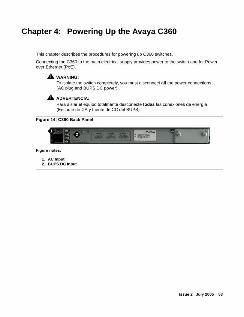
Figure 14: C360 Back Panel
Figure notes:
1. AC Input2. BUPS DC Input
12
Powering Up the Avaya C360
54 Installation and Configuration Guide Avaya C360 Multilayer Stackable Switches, version 4.5
Connecting to an AC Power Supply
AC Power CableThe C360 switch is supplied with a North American power cordset. Below are guidelines that should be used when obtaining and/or defining a different cordset to be used with the C360. The cordsets should be further verified for safety requirements of the particular application by a safety and regulatory professional:
For 200 to 240V applications, the cord must be VDE Certified or Harmonized (HAR), rated 250V, 3-conductor (3rd wire ground), 1.0 mm2 minimum conductor size. The cord is to be terminated at one end to a VDE Certified/CE Marked IEC 60320, sheet C13 type connector rated 10A, 250V and the other end to a 3-conductor grounding type attachment plug rated at a minimum of 10A, 250V and a configuration specific for the region/country in which it will be used. The attachment plug must bear the safety agency certifications mark(s) for the region/country of installation.
● For North American installations, a UL Listed and CSA Certified 15A branch circuit protective device must be provided in the building AC mains wiring installation for branch circuit protection.
● For other installations, a suitable and certified 10A branch protective device must be provided in the building AC mains wiring installation.
Tip:Tip: You may order certain cordsets from Avaya.
The C360 is rated 100-240 V~, 50-60 Hz. The maximum input current depends on the specific C360 model
1. Insert the AC power cord into the power inlet in the back of the unit.
2. Insert the AC plug into the AC power supply.
● The unit powers up.
● The C360 performs a self test procedure.
3. Connect the BUPS DC power supply (if applicable).
Connecting a BUPS
Issue 2 July 2005 55
Connecting a BUPSIf you deploy a BUPS with the C360, the APC (Advanced Power Conversion PLC) Front End AC-DC Power Shelf (model APC-R2400A111) with APC 800W PSUs (models APC-A0800-085-545-CA1) are to be used.The applied voltage at the C360 BUPS DC terminal block should be from 52 to 55 VDC.
The Isolation must be 1500V RMS with respect to protective ground
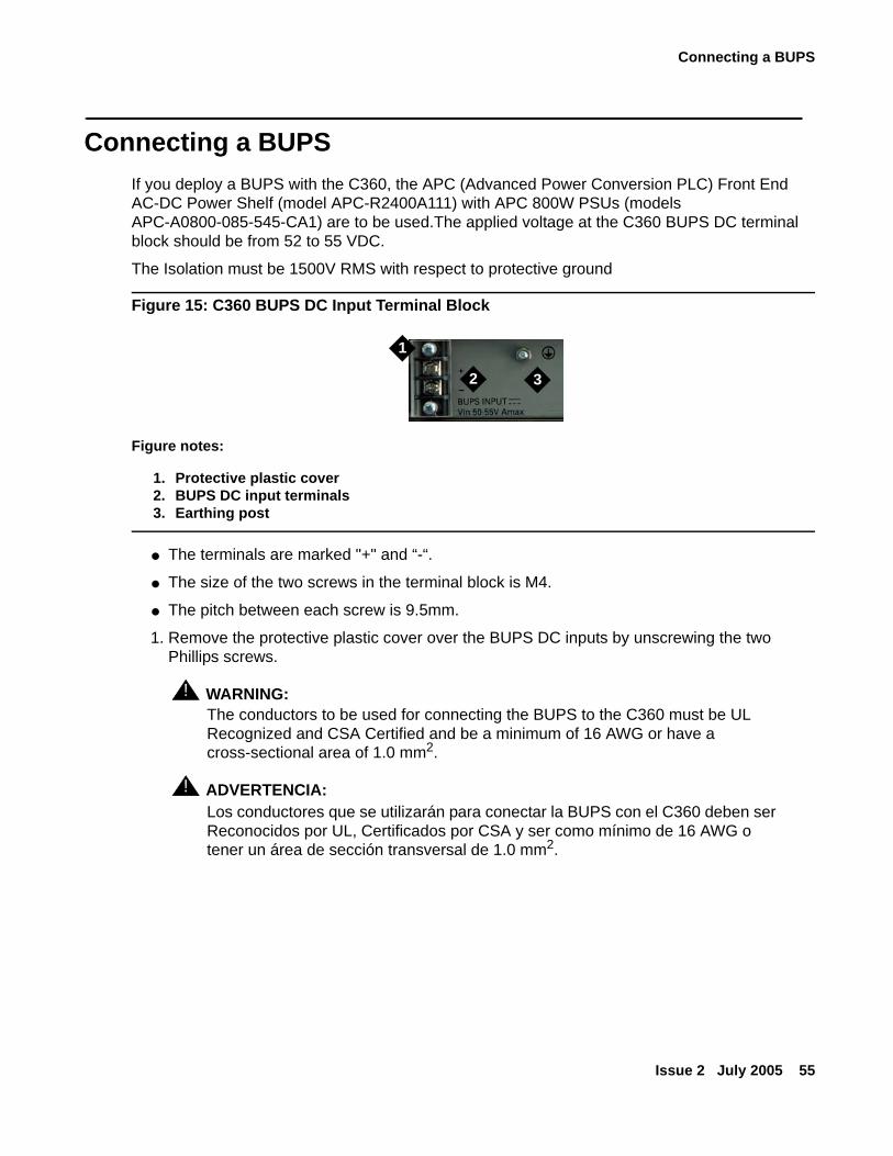
Figure 15: C360 BUPS DC Input Terminal Block
● The terminals are marked "+" and “-“.
● The size of the two screws in the terminal block is M4.
● The pitch between each screw is 9.5mm.
1. Remove the protective plastic cover over the BUPS DC inputs by unscrewing the two Phillips screws.
! WARNING:WARNING: The conductors to be used for connecting the BUPS to the C360 must be UL
Recognized and CSA Certified and be a minimum of 16 AWG or have a cross-sectional area of 1.0 mm2.
! ADVERTENCIA:ADVERTENCIA: Los conductores que se utilizarán para conectar la BUPS con el C360 deben ser
Reconocidos por UL, Certificados por CSA y ser como mínimo de 16 AWG o tener un área de sección transversal de 1.0 mm2.
Figure notes:
1. Protective plastic cover2. BUPS DC input terminals3. Earthing post
1
2 3

Powering Up the Avaya C360
56 Installation and Configuration Guide Avaya C360 Multilayer Stackable Switches, version 4.5
2. Connect the power cable to the terminals on the C360 and then external DC power supply.
! WARNING:WARNING: Make sure that you connect the cables between the C360 and the external power
supply correctly:
● Positive (“+") to positive (“+")
● Negative (“-") to negative (“-")
! ADVERTENCIA:ADVERTENCIA: Asegúrese que las polaridades de los cables entre el C360 y la fuente de
alimentación externa estén conectados correctamente:
● Positivo ("+") a Positivo ("+")
● Negativo ("-") a Negativo ("-")
3. Replace the plastic cover by aligning the holes with the screw receptacles and replacing the two Phillips screws.
Supplemental Earthing of the C360 (Optional)When connecting a BUPS to the C360, you must also connect a ground wire to the ground stud provided on the rear of the unit. This ground conductor must be green/yellow, a minimum of 16 AWG and be terminated with a lug that is suitable for the M4 stud provided. The other end of the ground conductor is to be terminated to a suitable building ground point such as a cold water pipe.
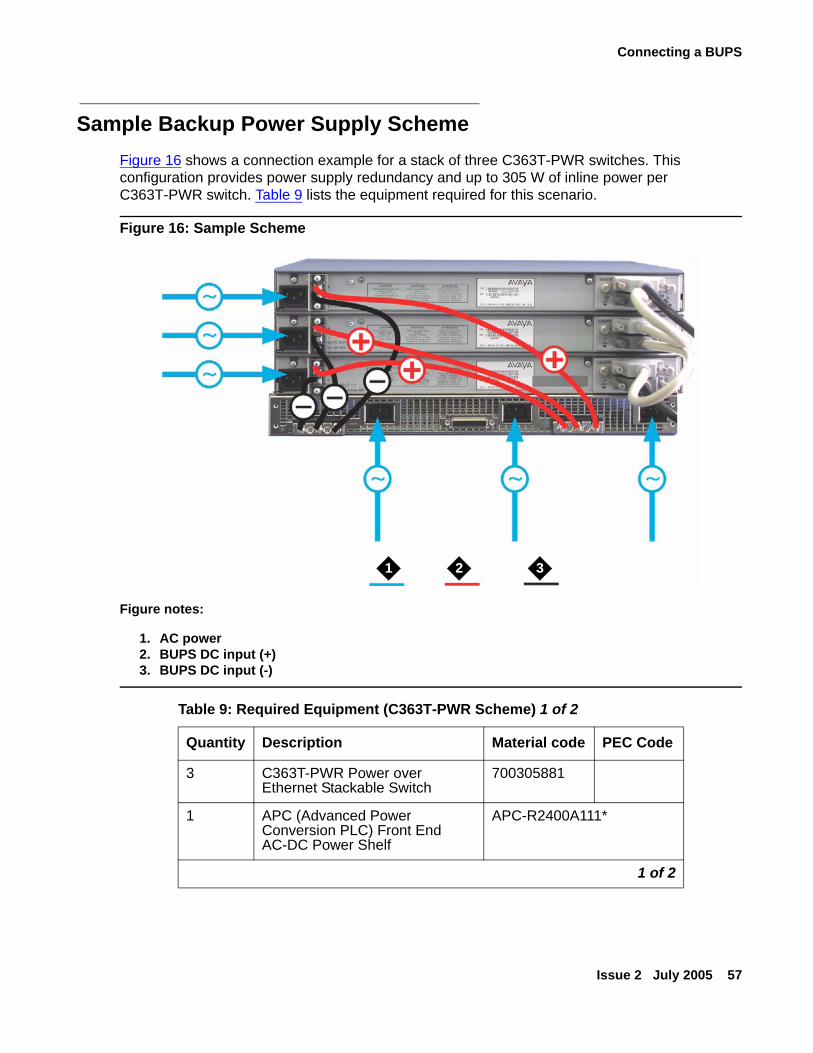
Connecting a BUPS
Issue 2 July 2005 57
Sample Backup Power Supply SchemeFigure 16 shows a connection example for a stack of three C363T-PWR switches. This configuration provides power supply redundancy and up to 305 W of inline power per C363T-PWR switch. Table 9 lists the equipment required for this scenario.
Figure 16: Sample Scheme
Figure notes:
1. AC power2. BUPS DC input (+)3. BUPS DC input (-)
Table 9: Required Equipment (C363T-PWR Scheme) 1 of 2
Quantity Description Material code PEC Code
3 C363T-PWR Power over Ethernet Stackable Switch
700305881
1 APC (Advanced Power Conversion PLC) Front End AC-DC Power Shelf
APC-R2400A111*
1 of 2
2 31
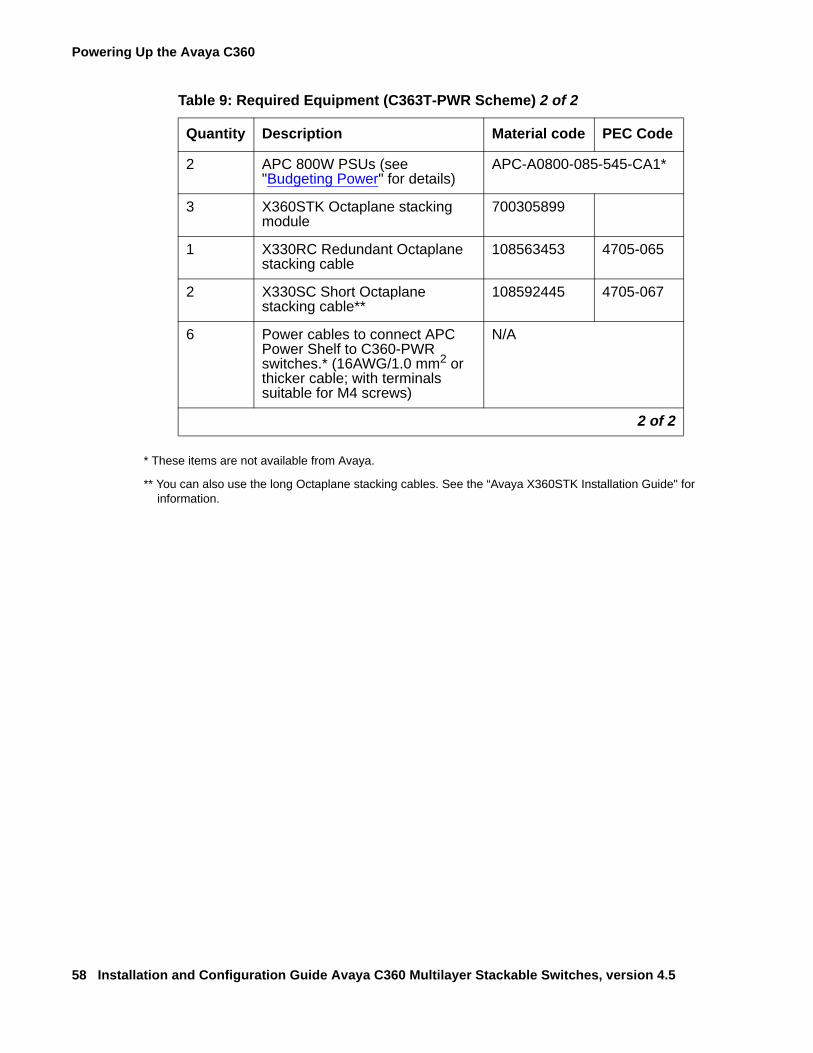
Powering Up the Avaya C360
58 Installation and Configuration Guide Avaya C360 Multilayer Stackable Switches, version 4.5
* These items are not available from Avaya.
** You can also use the long Octaplane stacking cables. See the “Avaya X360STK Installation Guide" for information.
2 APC 800W PSUs (see "Budgeting Power" for details)
APC-A0800-085-545-CA1*
3 X360STK Octaplane stacking module
700305899
1 X330RC Redundant Octaplane stacking cable
108563453 4705-065
2 X330SC Short Octaplane stacking cable**
108592445 4705-067
6 Power cables to connect APC Power Shelf to C360-PWR switches.* (16AWG/1.0 mm2 or thicker cable; with terminals suitable for M4 screws)
N/A
Table 9: Required Equipment (C363T-PWR Scheme) 2 of 2
Quantity Description Material code PEC Code
2 of 2
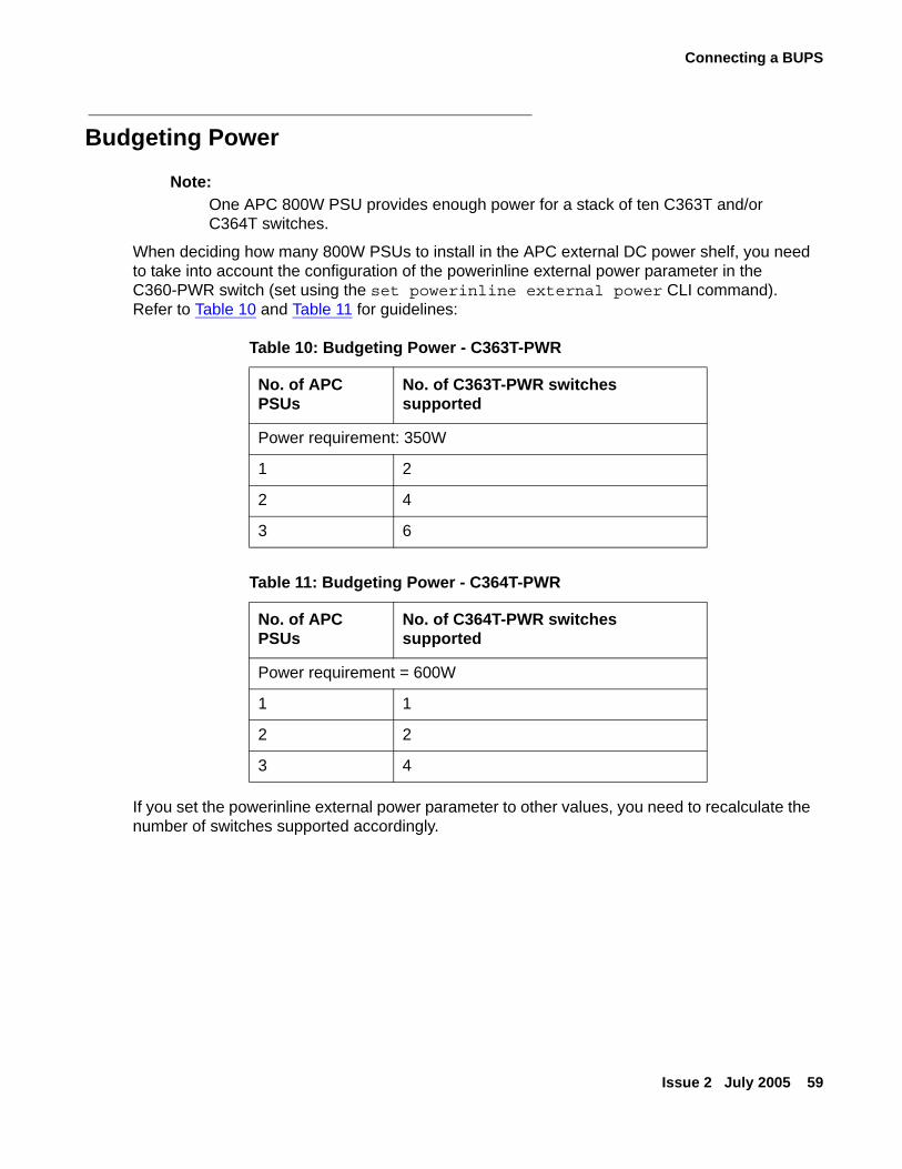
Connecting a BUPS
Issue 2 July 2005 59
Budgeting Power
Note:Note: One APC 800W PSU provides enough power for a stack of ten C363T and/or
C364T switches.
When deciding how many 800W PSUs to install in the APC external DC power shelf, you need to take into account the configuration of the powerinline external power parameter in the C360-PWR switch (set using the set powerinline external power CLI command). Refer to Table 10 and Table 11 for guidelines:
If you set the powerinline external power parameter to other values, you need to recalculate the number of switches supported accordingly.
Table 10: Budgeting Power - C363T-PWR
No. of APC PSUs
No. of C363T-PWR switches supported
Power requirement: 350W
1 2
2 4
3 6
Table 11: Budgeting Power - C364T-PWR
No. of APC PSUs
No. of C364T-PWR switches supported
Power requirement = 600W
1 1
2 2
3 4
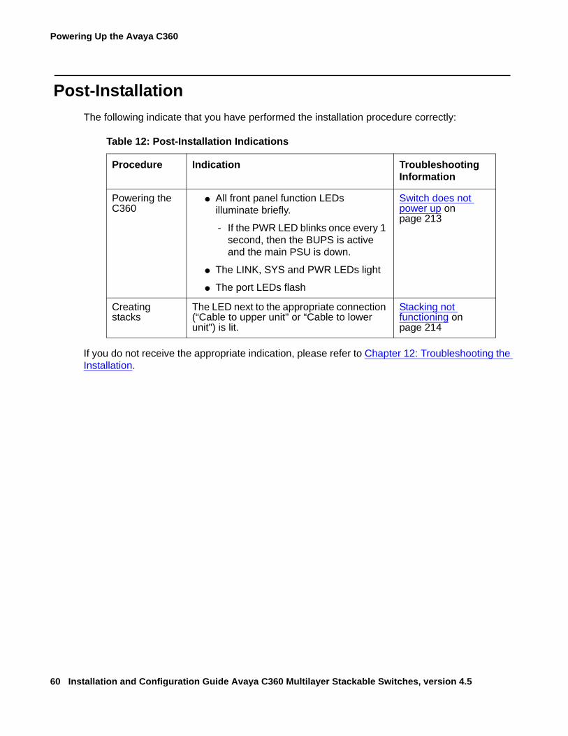
Powering Up the Avaya C360
60 Installation and Configuration Guide Avaya C360 Multilayer Stackable Switches, version 4.5
Post-InstallationThe following indicate that you have performed the installation procedure correctly:
If you do not receive the appropriate indication, please refer to Chapter 12: Troubleshooting the Installation.
Table 12: Post-Installation Indications
Procedure Indication Troubleshooting Information
Powering the C360
● All front panel function LEDs illuminate briefly.
- If the PWR LED blinks once every 1 second, then the BUPS is active and the main PSU is down.
● The LINK, SYS and PWR LEDs light
● The port LEDs flash
Switch does not power up on page 213
Creating stacks
The LED next to the appropriate connection (“Cable to upper unit" or “Cable to lower unit") is lit.
Stacking not functioning on page 214
Issue 2 July 2005 61
Chapter 5: Establishing Switch Access
This chapter describes various methods for accessing the C360 CLI and logging in with the appropriate security level:
C360 CLI● CLI Architecture
● Security Levels
● Entering the CLI
Establishing Connections● Establishing a Console Connection
● Assigning C360 IP Stack Address
● Establishing a Telnet Connection
● Establishing an SSH Connection
● Establishing Access to Other Entities in the Stack (C360 Sessions)
● Establishing a Modem (PPP) Connection
● SNMP Support
Security● RADIUS
● Recovery Password
● Allowed Managers
● Allowed Protocols
Establishing Switch Access
62 Installation and Configuration Guide Avaya C360 Multilayer Stackable Switches, version 4.5
CLI ArchitectureThe C360 stack supports both Layer 2 switching and Layer 3 switching. The C360 CLI includes two CLI entities to support this functionality.
● The Switch CLI entity is used to manage Layer 2 switching of the entire stack. CLI commands for managing Layer 2 switching are described in the Reference Guide for the Avaya C360 Converged Stackable Switch, 10-300506.
● The Router CLI entity is used to manage Layer 3 switching of a single module. CLI commands for managing Layer 3 switching are described in the Reference Guide for the Avaya C360 Converged Stackable Switch, 10-300506.
To switch between the entities, use the session command.
Security LevelsThere are three security access levels - User, Privileged, and Supervisor.
● The User level ('read-only') is a general access level used to show system parameter values.
● The Privileged level ('read-write') is used by site personnel to access stack configuration options.
● The Supervisor level ('administrator') is used to define user names, passwords, and access levels of up to 10 local CLI users, configure SNMPv1 community, configure SNMPv3, configure RADIUS authentication and control access protocols to the device.
Tip:Tip: If you wish to define more than ten users per switch, or accounts for a user on
multiple switches, use RADIUS (Remote Authentication Dial-In User Service).
A login name and password are always required to access the CLI and the commands. The login name, password, and access-type (i.e., security level) for a user account are established using the username command.
Switching between the entities does not effect the security level since security levels are established specifically for each user. For example, if the operator with a privileged security level in the Switch entity switches to the Router entity, the privileged security level is retained.
Tip:Tip: If you wish to increase security, you can disable SNMPv1 and allow only
SNMPv3.
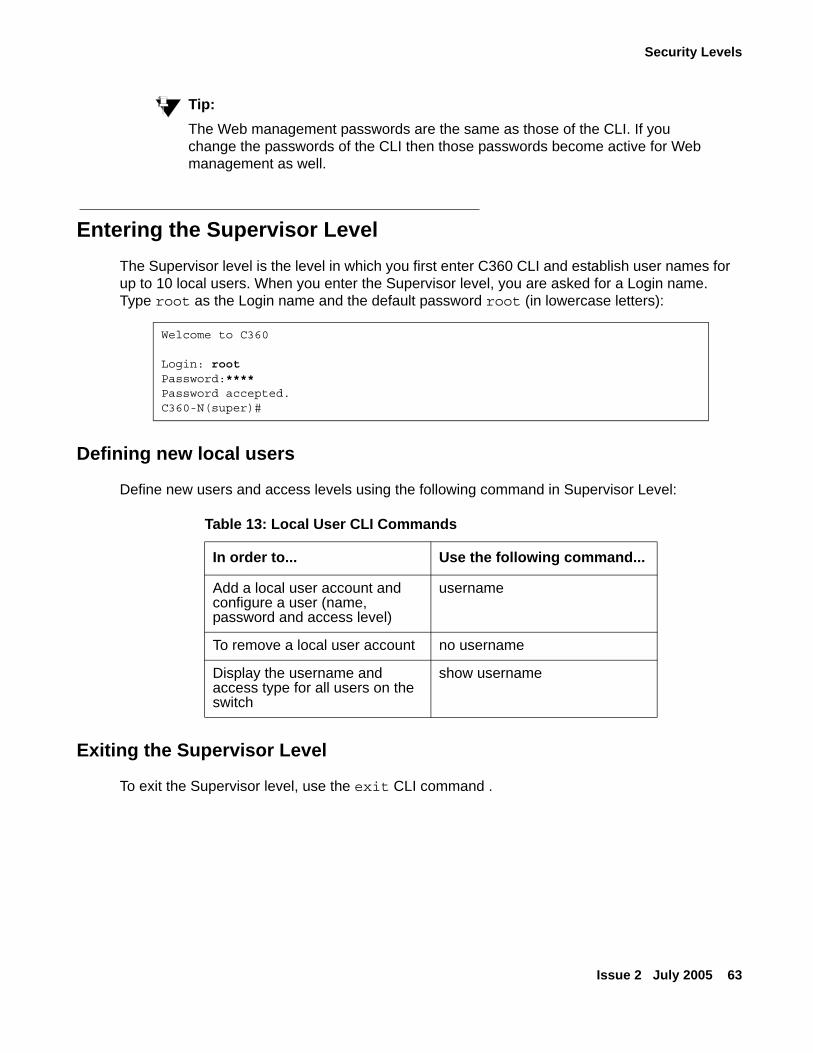
Security Levels
Issue 2 July 2005 63
Tip:Tip: The Web management passwords are the same as those of the CLI. If you
change the passwords of the CLI then those passwords become active for Web management as well.
Entering the Supervisor Level The Supervisor level is the level in which you first enter C360 CLI and establish user names for up to 10 local users. When you enter the Supervisor level, you are asked for a Login name. Type root as the Login name and the default password root (in lowercase letters):
Defining new local users
Define new users and access levels using the following command in Supervisor Level:
Exiting the Supervisor Level
To exit the Supervisor level, use the exit CLI command .
Welcome to C360
Login: rootPassword:****Password accepted.C360-N(super)#
Table 13: Local User CLI Commands
In order to... Use the following command...
Add a local user account and configure a user (name, password and access level)
username
To remove a local user account no username
Display the username and access type for all users on the switch
show username
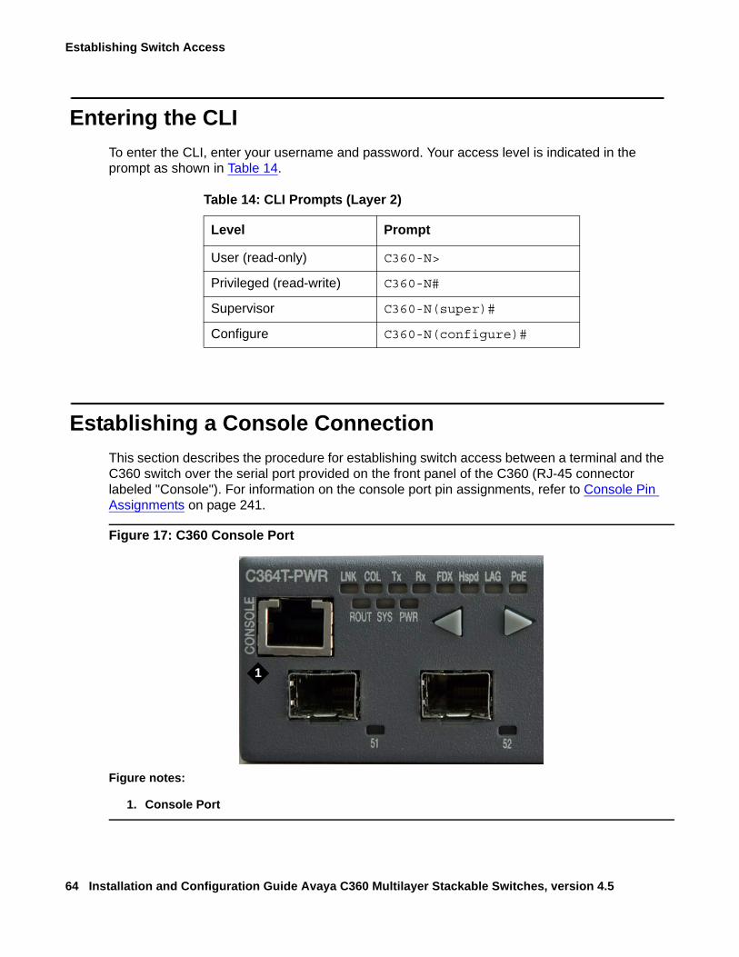
Establishing Switch Access
64 Installation and Configuration Guide Avaya C360 Multilayer Stackable Switches, version 4.5
Entering the CLITo enter the CLI, enter your username and password. Your access level is indicated in the prompt as shown in Table 14.
Establishing a Console ConnectionThis section describes the procedure for establishing switch access between a terminal and the C360 switch over the serial port provided on the front panel of the C360 (RJ-45 connector labeled "Console"). For information on the console port pin assignments, refer to Console Pin Assignments on page 241.
Figure 17: C360 Console Port
Table 14: CLI Prompts (Layer 2)
Level Prompt
User (read-only) C360-N>
Privileged (read-write) C360-N#
Supervisor C360-N(super)#
Configure C360-N(configure)#
Figure notes:
1. Console Port
1
Establishing a Console Connection
Issue 2 July 2005 65
1. Use the serial cable supplied to attach the RJ-45 console connector to the Console port of the master C360. Connect the DB-9 connector to the serial (COM) port on your PC/terminal.
- The master C360 is indicated by the SYS LED being ON.
2. Ensure that the serial port settings on the terminal are:
● 9600 baud
● 8 bits
● 1 stop bit
● no parity.
- If you reset or powered up the switch after connecting and configuring the terminal, Welcome to C360 appears followed by the Login Name prompt.
- If the login prompt does not appear, press a key on the terminal.
3. Enter the default login: root.
- The Password prompt appears
4. Enter the user level password: root.
- You can now establish a connection to the Router or the Master switch (indicated when the SYS front panel LED is ON) using the Session commands and begin the configuration of module, stack, or router parameters.
Establishing Switch Access
66 Installation and Configuration Guide Avaya C360 Multilayer Stackable Switches, version 4.5
Assigning C360 IP Stack AddressNote:
Note: All C360 switches are shipped with the same default IP address. You must change the IP address of the master C360 switch in a stack in order to guarantee that the stack has its own unique IP address in the network.
The network management station or a workstation running a Telnet client can establish communications with the stack once this address had been assigned and the stack has been inserted into the network. Use the CLI to assign the C360 stack an IP address and net mask.
To assign a C360 IP stack address:
1. Establish a serial connection by connecting a terminal to the master C360 switch of the stack.
2. When prompted for a Login Name, enter the default name root
3. When you are prompted for a password, enter the password root. You are now in Supervisor Level.
4. At the prompt, type:set interface inband <vlan> <ip_address> <netmask>Replace <vlan>, <ip_address> and <netmask> with the VLAN, IP address, and net mask of the stack.
5. Press Enter to save the IP address and net mask.
6. At the prompt, type reset. Type y and press Enter to reset the stack. After the Reset, log in again as described above.
- At the prompt, type set ip route <dest> <gateway> and replace <dest> and <gateway> with the destination and gateway IP addresses.
Establishing a Telnet Connection
Issue 2 July 2005 67
Establishing a Telnet ConnectionPerform the following steps to establish a Telnet connection to the C360 for configuration of Stack or Router parameters. You can Telnet the Stack Master IP address:
1. Connect your station to the network.
2. Verify that you can communicate with the C360 by pinging the IP of the C360. If there is no response using ping, check the IP address and default gateway of both the C360 and the station.
Tip:Tip: The C360 default IP address is 149.49.32.134 and the default subnet mask is
255.255.255.0.
3. From the Microsoft Windows taskbar of your PC click Start and then Run (or from the DOS prompt of your PC), then start the Telnet session by typing: telnet <C360_IP_address> For example: telnet 149.49.32.134
4. If the IP Address in the Telnet command is the IP address of the stack, then connection is established with the Switch CLI entity of the Master module.
● The "Welcome to C360" screen appears
5. Enter the default name root at the Login name prompt.
6. Enter the User Level password root in lower case letters (do not use uppercase letters) at the Password prompt.
● The User level prompt will appear when you have established communications with the C360.You can now configure the C360 stack and change its IP address.
Establishing Switch Access
68 Installation and Configuration Guide Avaya C360 Multilayer Stackable Switches, version 4.5
Establishing an SSH Connection
Introduction to SSHSSH (Secure Shell) protocol is a security protocol that enables establishing a remote session over a secured tunnel, also called a remote shell. SSH accomplishes this by creating a transparent encrypted channel between the local and remote devices. In addition to remote shell, SSH also provides secure file transfer between the local and remote devices.
SSH protocol currently has 2 versions, SSH1 and SSH2. SSH2 provides better security protection, key distribution services, and public key certificates than SSH1. SSH2 also has modular architecture which enables extension authentication and encryption techniques superior to SSH1. The OpenSSH package that Avaya uses for SSH implementation only supports SSH2.
SSH uses password authentication.
A maximum of two SSH sessions can be active per router in the stack, with two additional active SSH sessions per stack. For example, if a stack contains three router modules, a maximum of eight SSH sessions can be active on the stack.
The C360 agent reports SSH sessions opened to it. In addition, each router module reports the SSH sessions opened to its router interface. You can disconnect selected SSH sessions.
The SSH session-establishment process is divided into the following stages, as shown in Figure 18:
SSH client connection:To connect the SSH client:
1. The C360 and the SSH client initiate protocol handshake by exchanging the version number and list of supported ciphers. This step is completed by agreement on the cipher to be used for SSH secure tunnel. In addition, the client sends the C360 a unique session id used to prevent replay attack.
2. The Diffie-Hellman protocol is then used to setup the shared session key. During this step, the client and C360 exchange the DH (Diffie-Hellman) parameters, i.e., the prime number p and the generator number g used by each party for deriving its private and public keys.
3. The client sends to C360 min., max and preferred values for p and the C360 sends client p and g values. In response, the client uses them to derive its DH private key x and its DH public key values by exponentiation of g with x, e = (g^x)mod p and sends the value e to the C360
Establishing an SSH Connection
Issue 2 July 2005 69
4. The C360 derives its DH private key y and its DH public key f=(g^y)mod p, and sends the f value to the client, its public host key and the digital signature calculated for all values exchanged so far including f and public host key. The C360 uses DSA cipher and its host private key to calculate the signature.
5. The SSH client verifies the C360 identity. It checks the C360 host public key validity against the ~/.ssh/known_host file. This is the prompt that user receives if he or she connects to an unknown SSH server. It checks the known_hosts file for the host key offered by the server and prompts if it is not there or if it has changed
6. The SSH client verifies digital signature by decrypting it with DSA and the C360 host public key. This and the step above are essential to prevent a "man-in-the middle" attack by someone taking the C360 identity.
7. Using combination of each other public keys and their own private keys both parties now to calculate Diffie-Hellman shared secret. C360 calculate the shared secret K=f^x mod p and the client calculates K=e^ymod p. Both end up with the same value because of commutativity of exponentiation. The shared key is never sent on wire ensuring its secrecy. The shared session key used then for deriving the TDES symmetric key. All messages exchanged between the parties from this point are encrypted with TDES using the derived TDES key.
User AuthenticationBefore any data is transferred, the C360 requires the client to supply a user name and static password. This authenticates the user on the client side to the C360.
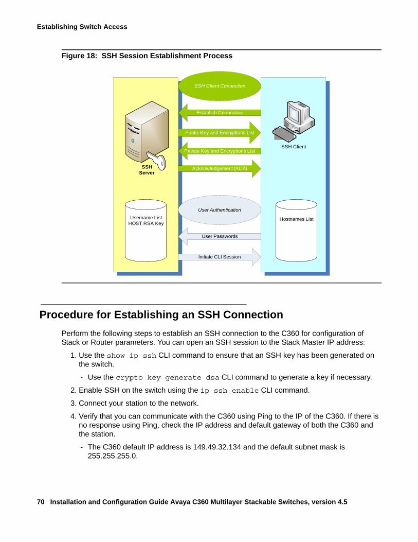
Establishing Switch Access
70 Installation and Configuration Guide Avaya C360 Multilayer Stackable Switches, version 4.5
Figure 18: SSH Session Establishment Process
Procedure for Establishing an SSH ConnectionPerform the following steps to establish an SSH connection to the C360 for configuration of Stack or Router parameters. You can open an SSH session to the Stack Master IP address:
1. Use the show ip ssh CLI command to ensure that an SSH key has been generated on the switch.
- Use the crypto key generate dsa CLI command to generate a key if necessary.
2. Enable SSH on the switch using the ip ssh enable CLI command.
3. Connect your station to the network.
4. Verify that you can communicate with the C360 using Ping to the IP of the C360. If there is no response using Ping, check the IP address and default gateway of both the C360 and the station.
- The C360 default IP address is 149.49.32.134 and the default subnet mask is 255.255.255.0.
SSHServer
SSH Client
Username ListHOST RSA Key
Hostnames List
Initiate CLI Session
User Passwords
User Authentication
SSH Client Connection
Public Key and Encryptions List
Establish Connection
Private Key and Encryptions List
Acknowledgement (ACK)
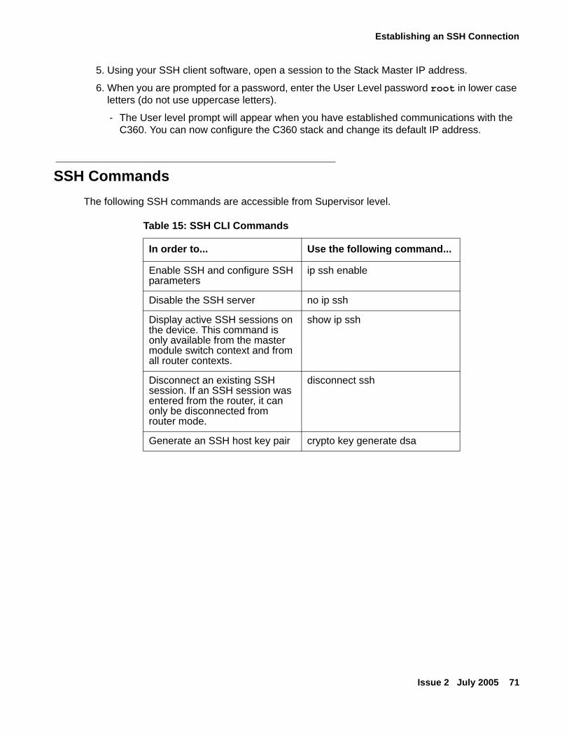
Establishing an SSH Connection
Issue 2 July 2005 71
5. Using your SSH client software, open a session to the Stack Master IP address.
6. When you are prompted for a password, enter the User Level password root in lower case letters (do not use uppercase letters).
- The User level prompt will appear when you have established communications with the C360. You can now configure the C360 stack and change its default IP address.
SSH CommandsThe following SSH commands are accessible from Supervisor level.
Table 15: SSH CLI Commands
In order to... Use the following command...
Enable SSH and configure SSH parameters
ip ssh enable
Disable the SSH server no ip ssh
Display active SSH sessions on the device. This command is only available from the master module switch context and from all router contexts.
show ip ssh
Disconnect an existing SSH session. If an SSH session was entered from the router, it can only be disconnected from router mode.
disconnect ssh
Generate an SSH host key pair crypto key generate dsa
Establishing Switch Access
72 Installation and Configuration Guide Avaya C360 Multilayer Stackable Switches, version 4.5
Establishing Access to Other Entities in the Stack (C360 Sessions)
You can use sessions to switch between the CLI of C360 switches, other stack entities, or to switch between Layer 2 and Layer 3 commands.
To switch between stack entities use the session [<mod_num>] <mode> CLI command.
● <mod_num> is the number of the switch in the stack, counting from the bottom.
● <mode> can be switch, router, wan, or mgp.
Use switch mode to configure layer 2 commands.
Use router mode to configure routing commands.
Examples:
To configure router parameters in the module that you are currently logged into, type the following command:
session router
To configure the switch parameters, on switch 6, type the command:session 6 switch.
Note:Note: When you use the session CLI command the security level stays the same.
Establishing a Modem (PPP) Connection
Issue 2 July 2005 73
Establishing a Modem (PPP) ConnectionPoint-to-Point Protocol (PPP) provides a Layer 2 method for transporting multi-protocol datagrams over modem links.
Connecting a Modem to the Console PortBefore you can establish a PPP connection with a modem can be established, you need to configure the following:
● C360 IP address: refer to Assigning C360 IP Stack Address for further information.
● net-mask
● PPP parameters that are compatible with the modem's PPP parameters.
1. Connect a terminal to the console port of the C360 switch as described in Connecting a Terminal to the C360 Serial port.
2. When you are prompted for a Login Name, enter the default name root.
3. When you are prompted for a password, enter the password root. You are now in Supervisor Level.
4. At the prompt, type:set interface ppp <ip_addr> <net-mask> with an IP address and netmask to be used by the C360 to connect via its PPP interface.
Note:Note: The PPP interface configured with the set interface ppp command must be
on a different subnet from the stack inband interface.
5. Set the baud rate, ppp authentication, and ppp time out required to match your modem. These commands are described in the Reference Guide for the Avaya C360 Converged Stackable Switch, 10-300506.
6. At the prompt, type:set interface ppp enable
● The CLI responds with the following: Entering the Modem mode within 60 seconds...Please check that the proprietary modem cable is plugged into the console port
7. Use the DB-25 to RJ-45 connector provided in the accessory kit to plug the console cable to the modem's DB-25 connector. Plug the other end of the cable RJ-45 connector to the C360 console's RJ-45 port.
8. The C360 enters modem mode.

Establishing Switch Access
74 Installation and Configuration Guide Avaya C360 Multilayer Stackable Switches, version 4.5
9. You can now dial into the switch from a remote station, and open a Telnet session to the PPP interface IP address.
SNMP Support
Issue 2 July 2005 75
SNMP Support
Introduction to SNMP
SNMP Versions
There are currently three versions of SNMP (Simple Network Management Protocol):
● SNMPv1
● SNMPv2c
● SNMPv3
The C360 supports device access using all three versions of SNMP.
Managers and Agents
SNMP uses software entities called managers and agents to manage network devices. The manager monitors and controls all other SNMP-managed devices or network nodes on the network. There must be at least one SNMP Manager in a managed network. The manager is installed on a workstation located on the network.
An agent resides in a managed device or network node. The agent receives instructions from the SNMP Manager, generates reports in response to requests from the SNMP Manager, and also sends management information back to the SNMP Manager as events occur. Each C360 module has an agent. However, on each C360 stack, one module is selected to be the master module. The stack is managed via the master module's agent.
There are many SNMP management applications, but all these applications perform the same basic task. They allow SNMP managers to communicate with agents to configure, get statistics and information, and receive alerts from network devices. You can use any SNMP-compatible network management system to monitor and control the C360.
Manager/Agent Communication
There are several ways that the SNMP manager and the agent communicate.
The manager can:
● Retrieve a value - a get action
The SNMP manager requests information from the agent, such as the link status of an Ethernet port or the number of good packets received on the switch. The agent gets the value of the requested MIB variable and sends the value back to the manager.
Establishing Switch Access
76 Installation and Configuration Guide Avaya C360 Multilayer Stackable Switches, version 4.5
● Retrieve the value immediately after the variable you name - a get-next action.
The SNMP manager retrieves values from the MIB tree. Using the get-next function, you do not need to know the exact variable name you are looking for. The SNMP manager takes the variable you name and then uses a sequential search to find the desired variable.
● Change a setting on the agent - a set action
The SNMP manager requests the agent to change the value of the MIB variable. For example, you can enable or disable a port.
● An agent can send an unsolicited message to the manager at any time if a significant, predetermined event takes place on the agent. This message is called a trap.
When a trap condition occurs, the SNMP agent sends an SNMP trap message to the specified trap receiver or trap host. The SNMP Administrator configures the trap host, usually the SNMP management station, to perform the action needed when a trap is detected.
SNMPv1SNMPv1 uses community strings to limit access rights. Each SNMP device is assigned to a read community and a read-write community. To communicate with a switch, you must send an SNMP packet with the relevant community name.
By default, if you communicate with a switch using only the read community, you are assigned the security name "ReadCommN". This security name is mapped to the "ReadCommG" group by default. This allows you to view the agent's MIB tree, but cannot change any of the values in the MIB tree.
If you communicate with a switch using the write community, you are assigned the security name "WriteCommN". This security name is mapped to the "WriteComm" group by default. This allows you to view the agent's MIB tree and change any of the values in the MIB tree.
! CAUTION:CAUTION: If you delete the ReadCommN or WriteCommN users, the ReadCommG or
WriteCommG groups, or the SNMPv1View you may not be able to access the switch using SNMPv1.
In addition, traps are sent to designated trap receivers. Packets with trap information also contains a trap community string.
SNMPv2cSNMPv2c is very similar to SNMPv1. However, SNMPv2c adds support for the get-bulk action and supports a different trap format.
SNMP Support
Issue 2 July 2005 77
SNMPv3SNMPv3 enables the following features over SNMPv1 or v2c:
● User authentication with a username and password. Authentication is performed using md5 or sha-1.
● Communication encryption between the Network Management Station (NMS) and the SNMP agent at the application level
● Access control definition for specific MIB items available on the SNMP agent
● Notification of specified network events directed toward specified users
● Definition of roles using access control, each with unique access permissions and authentication/encryption requirements
The basic components in SNMPv3 access control are users, groups, and views.
In addition. SNMPv3 uses an SNMP engine ID to identify an SNMP entity. An SNMP engine ID is assigned to each IP address of each device in the network. Each SNMP engine ID should be unique in the network.
Users
SNMPv3 uses the User-based Security Model (USM) for security, and the View-based Access Control Model (VACM) for access control. USM uses the HMAC-MD5-96 and HMAC-SHA-96 protocols for user authentication, and the CBC-DES56 protocol for encryption.
A maximum of 21 users, including local users and remote users getting notifications can be defined on a stack. If the SNMP engine ID changes, all users other than the default user for the stack are invalid and must be redefined. The SNMP engine ID can be changed via the CLI. In addition, a change in the IP address of the stack automatically changes the SNMP engine ID.
SNMPv3 supports three security levels:
● NoAuthNoPriv - This is the lowest level of SNMPv3 security. No authentication is done and no encryption is performed. This method is maintains the same security level as SNMPv1, but provides a method for limiting the access rights of a user.
● AuthNoPriv - User authentication is performed based on MD5 or SHA algorithms. The message is sent with an HMAC that is calculated with the user key. The data part is sent unencrypted.
● AuthPriv - User authentication is performed based on MD5 or SHA algorithms. 'The message is sent with HMAC for authentication, and encrypted using DES.
To create an SNMPv3 user account, you must provide the following information:
● UserName - string representing the name of the user.
● Maximum length: 32 characters.
Establishing Switch Access
78 Installation and Configuration Guide Avaya C360 Multilayer Stackable Switches, version 4.5
● Authentication Protocol - The authentication protocol to use. Possible values are: No auth, HMAC MD5, or HMAC SHA-1.
● Authentication Password - The authentication password is transformed using the authentication protocol and the SNMP engine ID to create an authentication key.
● Privacy Protocol - The privacy protocol to use. Possible values are: No privacy, DES privacy.
● Privacy Password - The privacy password is transformed using the privacy protocol and the SNMP engine ID to create a privacy key.
● GroupName - a string of up to 32 characters representing the name of the group.
● SecurityModel - The security model to use. Possible values are: 1 (SNMPv1), 2 (SNMPv2c), 3 (USM).
Groups
In SNMPv3, each user is mapped to a group. The group maps its users to defined views. These views define sets of access rights, including read, write, and trap or inform notifications the users can send.
The group maps its users to views based on the security model and level with which the user is communicating with the switch. Within a group, the following combinations of security model and level can be mapped to views:
● SNMPv1 - Only requests using SNMPv1 or higher.
● SNMPv2c - Only requests using SNMPv2 or higher.
● NoAuthNoPriv - An SNMPv3 user using the NoAuthNoPriv security level.
● AuthNoPriv - An SNMPv3 user using the AuthNoPriv security level.
● AuthPriv - An SNMPv3 user using the AuthPriv security level.
If a group with the specific security model and level does not exist, then a user can access a group with lower security model or level. If an SNMPv3 group with NoAuthNoPriv security level is not defined, SNMPv3 users with a NoAuthNoPriv security level can access the SNMPv2c view.
To create an SNMPv3 group, you must provide the following information:
● GroupName - String of up to 32 characters representing the name of the group.
● Security model:
- SNMPv1
- SNMPv2c
- SNMPv3
● Security level (for SNMPv3 only):
- NoAuthNoPriv
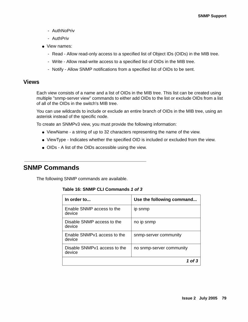
SNMP Support
Issue 2 July 2005 79
- AuthNoPriv
- AuthPriv
● View names:
- Read - Allow read-only access to a specified list of Object IDs (OIDs) in the MIB tree.
- Write - Allow read-write access to a specified list of OIDs in the MIB tree.
- Notify - Allow SNMP notifications from a specified list of OIDs to be sent.
Views
Each view consists of a name and a list of OIDs in the MIB tree. This list can be created using multiple "snmp-server view" commands to either add OIDs to the list or exclude OIDs from a list of all of the OIDs in the switch's MIB tree.
You can use wildcards to include or exclude an entire branch of OIDs in the MIB tree, using an asterisk instead of the specific node.
To create an SNMPv3 view, you must provide the following information:
● ViewName - a string of up to 32 characters representing the name of the view.
● ViewType - Indicates whether the specified OID is included or excluded from the view.
● OIDs - A list of the OIDs accessible using the view.
SNMP CommandsThe following SNMP commands are available.
Table 16: SNMP CLI Commands 1 of 3
In order to... Use the following command...
Enable SNMP access to the device
ip snmp
Disable SNMP access to the device
no ip snmp
Enable SNMPv1 access to the device
snmp-server community
Disable SNMPv1 access to the device
no snmp-server community
1 of 3
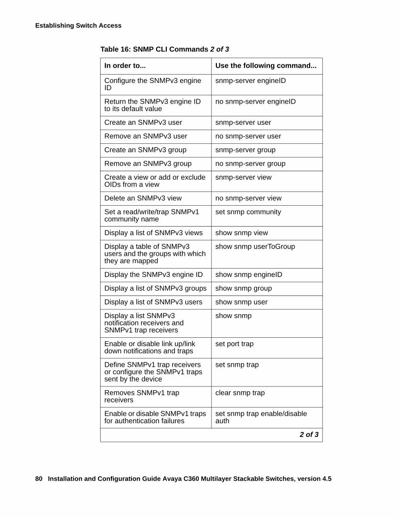
Establishing Switch Access
80 Installation and Configuration Guide Avaya C360 Multilayer Stackable Switches, version 4.5
Configure the SNMPv3 engine ID
snmp-server engineID
Return the SNMPv3 engine ID to its default value
no snmp-server engineID
Create an SNMPv3 user snmp-server user
Remove an SNMPv3 user no snmp-server user
Create an SNMPv3 group snmp-server group
Remove an SNMPv3 group no snmp-server group
Create a view or add or exclude OIDs from a view
snmp-server view
Delete an SNMPv3 view no snmp-server view
Set a read/write/trap SNMPv1 community name
set snmp community
Display a list of SNMPv3 views show snmp view
Display a table of SNMPv3 users and the groups with which they are mapped
show snmp userToGroup
Display the SNMPv3 engine ID show snmp engineID
Display a list of SNMPv3 groups show snmp group
Display a list of SNMPv3 users show snmp user
Display a list SNMPv3 notification receivers and SNMPv1 trap receivers
show snmp
Enable or disable link up/link down notifications and traps
set port trap
Define SNMPv1 trap receivers or configure the SNMPv1 traps sent by the device
set snmp trap
Removes SNMPv1 trap receivers
clear snmp trap
Enable or disable SNMPv1 traps for authentication failures
set snmp trap enable/disable auth
Table 16: SNMP CLI Commands 2 of 3
In order to... Use the following command...
2 of 3
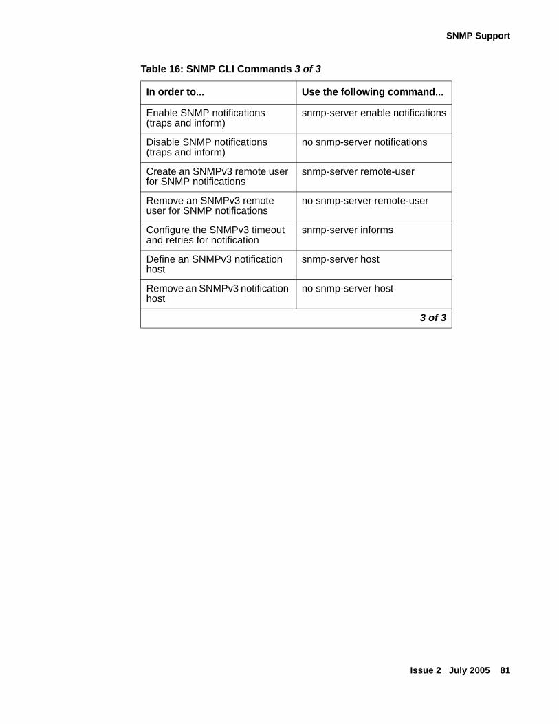
SNMP Support
Issue 2 July 2005 81
Enable SNMP notifications (traps and inform)
snmp-server enable notifications
Disable SNMP notifications (traps and inform)
no snmp-server notifications
Create an SNMPv3 remote user for SNMP notifications
snmp-server remote-user
Remove an SNMPv3 remote user for SNMP notifications
no snmp-server remote-user
Configure the SNMPv3 timeout and retries for notification
snmp-server informs
Define an SNMPv3 notification host
snmp-server host
Remove an SNMPv3 notification host
no snmp-server host
Table 16: SNMP CLI Commands 3 of 3
In order to... Use the following command...
3 of 3
Establishing Switch Access
82 Installation and Configuration Guide Avaya C360 Multilayer Stackable Switches, version 4.5
RADIUS
Introduction to RADIUSUser accounts are typically maintained locally on the switch. Therefore, if a site contains multiple Avaya Switches, it is necessary to configure each switch with its own user accounts. Additionally, if for example a "read-write" user has to be changed into a "read-only" user, you must change all the "read-write" passwords configured locally in every switch, in order to prevent him from accessing this level. This is obviously not effective management. A better solution is to have all of the user login information kept in a central location where all the switches can access it. C360 features such a solution: the Remote Authentication Dial-In User Service (RADIUS).
A RADIUS authentication server is installed on a central computer at the customer's site. On this server user authentication (account) information is configured that provides various degrees of access to the switch. The C360 will run as a RADIUS client. When a user attempts to log into the switch, if there is no local user account for the entered user name and password, then the switch will send an Authentication Request to the RADIUS server in an attempt to authenticate the user remotely. If the user name and password are authenticated, then the RADIUS server responds to the switch with an Authentication Acknowledgement that includes information on the user's privileges ("administrator", "read-write", or "read-only"), and the user is allowed to gain access to the switch. If the user is not authenticated, then an Authentication Reject is sent to the switch and the user is not allowed access to the switch's embedded management.
The Remote Authentication Dial-In User Service (RADIUS) is an IETF standard (RFC 2138) client/server security protocol. Security and login information is stored in a central location known as the RADIUS server. RADIUS clients, such as the C360, communicate with the RADIUS server to authenticate users.
All transactions between the RADIUS client and server are authenticated through the use of a "shared secret" which is not sent over the network. The shared secret is an authentication password configured on both the RADIUS client and its RADIUS servers. The shared secret is stored as clear text in the client's file on the RADIUS server, and in the non-volatile memory of the C360. In addition, user passwords sent between the client and server are encrypted for increased security.
In the C360, RADIUS is used to authenticate management stations and (independently) for 802.1x port-based access control.
Figure 19 illustrates the RADIUS authentication procedure:
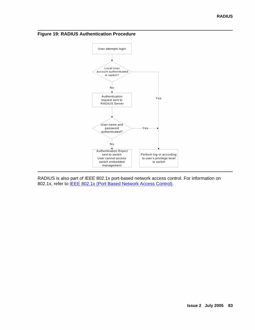
RADIUS
Issue 2 July 2005 83
Figure 19: RADIUS Authentication Procedure
RADIUS is also part of IEEE 802.1x port-based network access control. For information on 802.1x, refer to IEEE 802.1x (Port Based Network Access Control).
User attempts login
Local User account authenticated
in switch?
Perform log -in according to user's privilege level
to switch
YesAuthenticationrequest sent toRADIUS Server
No
User name and password
authenticated?Yes
Authentication Reject sent to switch
User cannot access switch embedded
management
No
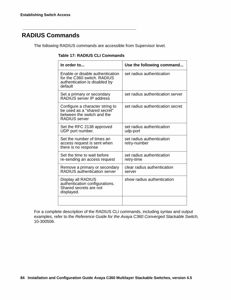
Establishing Switch Access
84 Installation and Configuration Guide Avaya C360 Multilayer Stackable Switches, version 4.5
RADIUS CommandsThe following RADIUS commands are accessible from Supervisor level.
For a complete description of the RADIUS CLI commands, including syntax and output examples, refer to the Reference Guide for the Avaya C360 Converged Stackable Switch, 10-300506.
Table 17: RADIUS CLI Commands
In order to... Use the following command...
Enable or disable authentication for the C360 switch. RADIUS authentication is disabled by default
set radius authentication
Set a primary or secondary RADIUS server IP address
set radius authentication server
Configure a character string to be used as a "shared secret" between the switch and the RADIUS server
set radius authentication secret
Set the RFC 2138 approved UDP port number.
set radius authentication udp-port
Set the number of times an access request is sent when there is no response
set radius authentication retry-number
Set the time to wait before re-sending an access request
set radius authentication retry-time
Remove a primary or secondary RADIUS authentication server
clear radius authentication server
Display all RADIUS authentication configurations. Shared secrets are not displayed.
show radius authentication
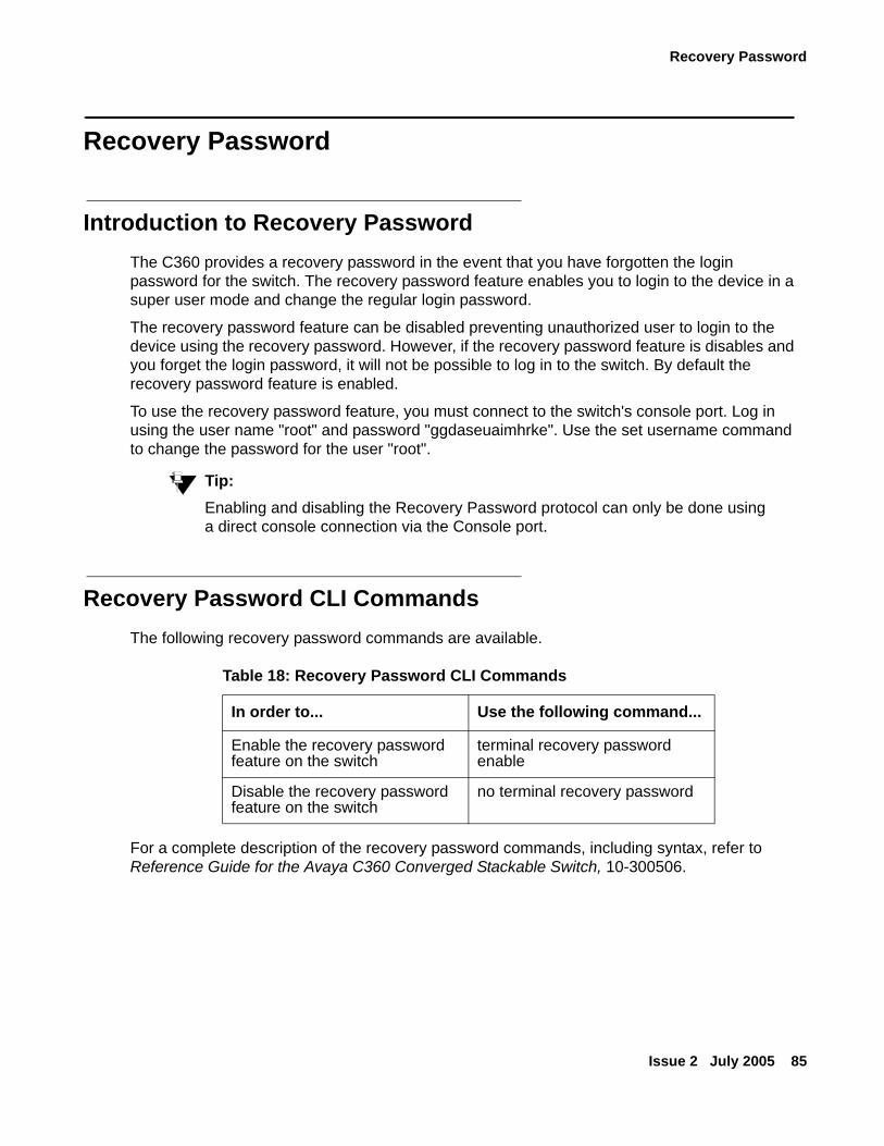
Recovery Password
Issue 2 July 2005 85
Recovery Password
Introduction to Recovery PasswordThe C360 provides a recovery password in the event that you have forgotten the login password for the switch. The recovery password feature enables you to login to the device in a super user mode and change the regular login password.
The recovery password feature can be disabled preventing unauthorized user to login to the device using the recovery password. However, if the recovery password feature is disables and you forget the login password, it will not be possible to log in to the switch. By default the recovery password feature is enabled.
To use the recovery password feature, you must connect to the switch's console port. Log in using the user name "root" and password "ggdaseuaimhrke". Use the set username command to change the password for the user "root".
Tip:Tip: Enabling and disabling the Recovery Password protocol can only be done using
a direct console connection via the Console port.
Recovery Password CLI Commands The following recovery password commands are available.
For a complete description of the recovery password commands, including syntax, refer to Reference Guide for the Avaya C360 Converged Stackable Switch, 10-300506.
Table 18: Recovery Password CLI Commands
In order to... Use the following command...
Enable the recovery password feature on the switch
terminal recovery password enable
Disable the recovery password feature on the switch
no terminal recovery password
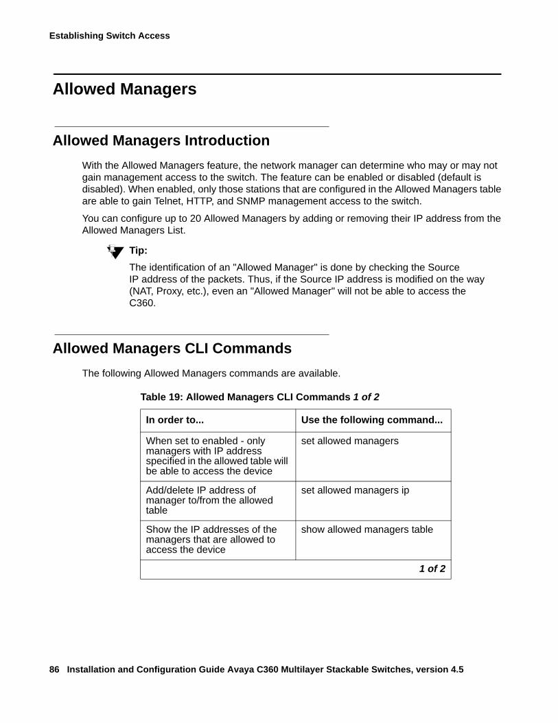
Establishing Switch Access
86 Installation and Configuration Guide Avaya C360 Multilayer Stackable Switches, version 4.5
Allowed Managers
Allowed Managers IntroductionWith the Allowed Managers feature, the network manager can determine who may or may not gain management access to the switch. The feature can be enabled or disabled (default is disabled). When enabled, only those stations that are configured in the Allowed Managers table are able to gain Telnet, HTTP, and SNMP management access to the switch.
You can configure up to 20 Allowed Managers by adding or removing their IP address from the Allowed Managers List.
Tip:Tip: The identification of an "Allowed Manager" is done by checking the Source
IP address of the packets. Thus, if the Source IP address is modified on the way (NAT, Proxy, etc.), even an "Allowed Manager" will not be able to access the C360.
Allowed Managers CLI CommandsThe following Allowed Managers commands are available.
Table 19: Allowed Managers CLI Commands 1 of 2
In order to... Use the following command...
When set to enabled - only managers with IP address specified in the allowed table will be able to access the device
set allowed managers
Add/delete IP address of manager to/from the allowed table
set allowed managers ip
Show the IP addresses of the managers that are allowed to access the device
show allowed managers table
1 of 2
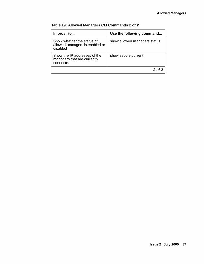
Allowed Managers
Issue 2 July 2005 87
Show whether the status of allowed managers is enabled or disabled
show allowed managers status
Show the IP addresses of the managers that are currently connected
show secure current
Table 19: Allowed Managers CLI Commands 2 of 2
In order to... Use the following command...
2 of 2
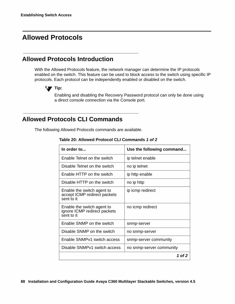
Establishing Switch Access
88 Installation and Configuration Guide Avaya C360 Multilayer Stackable Switches, version 4.5
Allowed Protocols
Allowed Protocols IntroductionWith the Allowed Protocols feature, the network manager can determine the IP protocols enabled on the switch. This feature can be used to block access to the switch using specific IP protocols. Each protocol can be independently enabled or disabled on the switch.
Tip:Tip: Enabling and disabling the Recovery Password protocol can only be done using
a direct console connection via the Console port.
Allowed Protocols CLI CommandsThe following Allowed Protocols commands are available.
Table 20: Allowed Protocol CLI Commands 1 of 2
In order to... Use the following command...
Enable Telnet on the switch ip telnet enable
Disable Telnet on the switch no ip telnet
Enable HTTP on the switch ip http enable
Disable HTTP on the switch no ip http
Enable the switch agent to accept ICMP redirect packets sent to it
ip icmp redirect
Enable the switch agent to ignore ICMP redirect packets sent to it
no icmp redirect
Enable SNMP on the switch snmp-server
Disable SNMP on the switch no snmp-server
Enable SNMPv1 switch access snmp-server community
Disable SNMPv1 switch access no snmp-server community
1 of 2
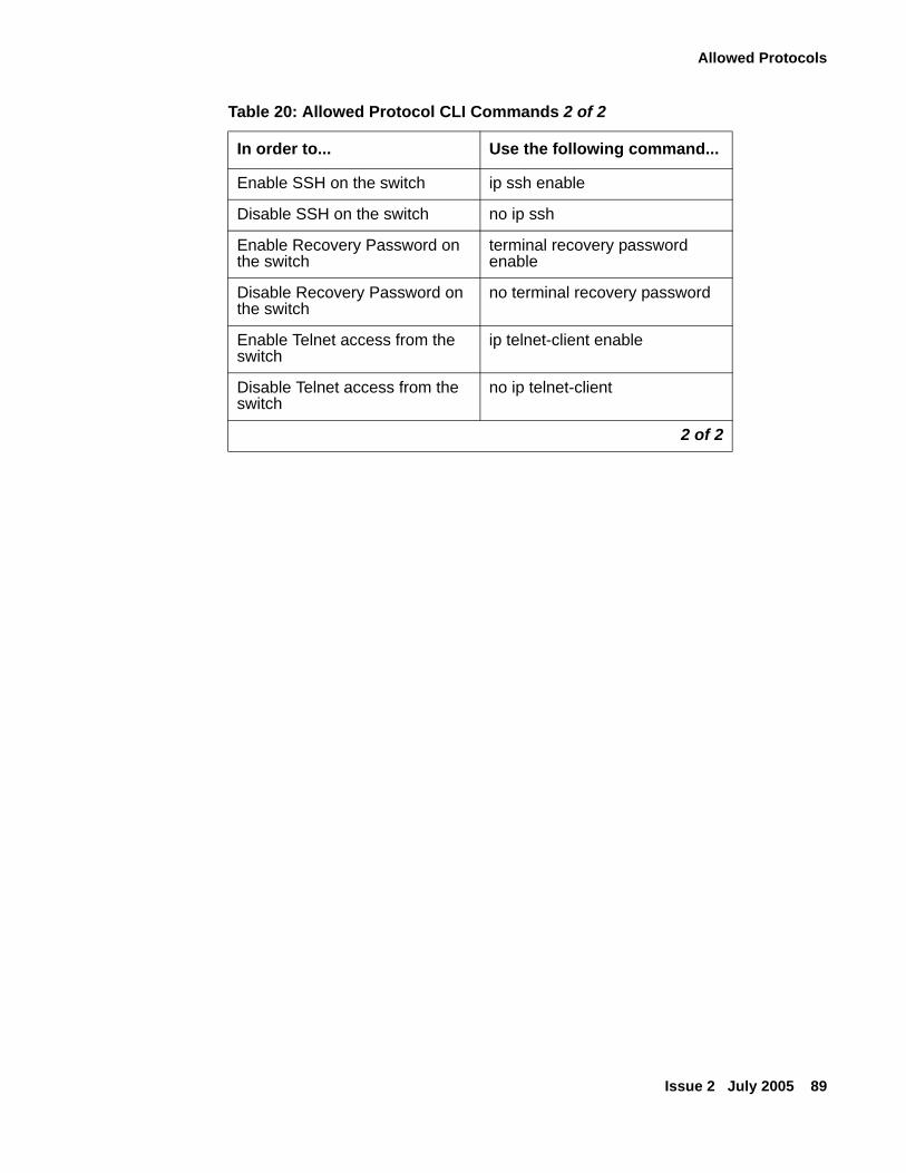
Allowed Protocols
Issue 2 July 2005 89
Enable SSH on the switch ip ssh enable
Disable SSH on the switch no ip ssh
Enable Recovery Password on the switch
terminal recovery password enable
Disable Recovery Password on the switch
no terminal recovery password
Enable Telnet access from the switch
ip telnet-client enable
Disable Telnet access from the switch
no ip telnet-client
Table 20: Allowed Protocol CLI Commands 2 of 2
In order to... Use the following command...
2 of 2

Establishing Switch Access
90 Installation and Configuration Guide Avaya C360 Multilayer Stackable Switches, version 4.5

Issue 2 July 2005 91
Section 3: Avaya C360 Configuration

92 Installation and Configuration Guide Avaya C360 Multilayer Stackable Switches, version 4.5
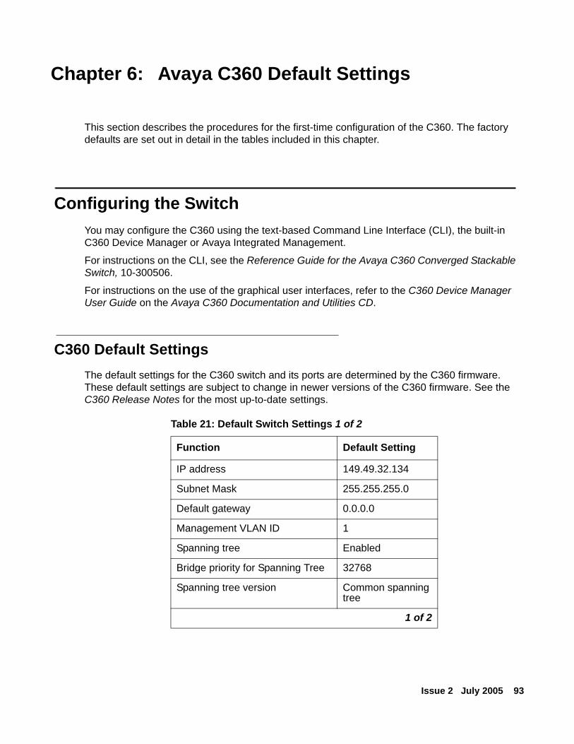
Issue 2 July 2005 93
Chapter 6: Avaya C360 Default Settings
This section describes the procedures for the first-time configuration of the C360. The factory defaults are set out in detail in the tables included in this chapter.
Configuring the SwitchYou may configure the C360 using the text-based Command Line Interface (CLI), the built-in C360 Device Manager or Avaya Integrated Management.
For instructions on the CLI, see the Reference Guide for the Avaya C360 Converged Stackable Switch, 10-300506.
For instructions on the use of the graphical user interfaces, refer to the C360 Device Manager User Guide on the Avaya C360 Documentation and Utilities CD.
C360 Default SettingsThe default settings for the C360 switch and its ports are determined by the C360 firmware. These default settings are subject to change in newer versions of the C360 firmware. See the C360 Release Notes for the most up-to-date settings.
Table 21: Default Switch Settings 1 of 2
Function Default Setting
IP address 149.49.32.134
Subnet Mask 255.255.255.0
Default gateway 0.0.0.0
Management VLAN ID 1
Spanning tree Enabled
Bridge priority for Spanning Tree 32768
Spanning tree version Common spanning tree
1 of 2
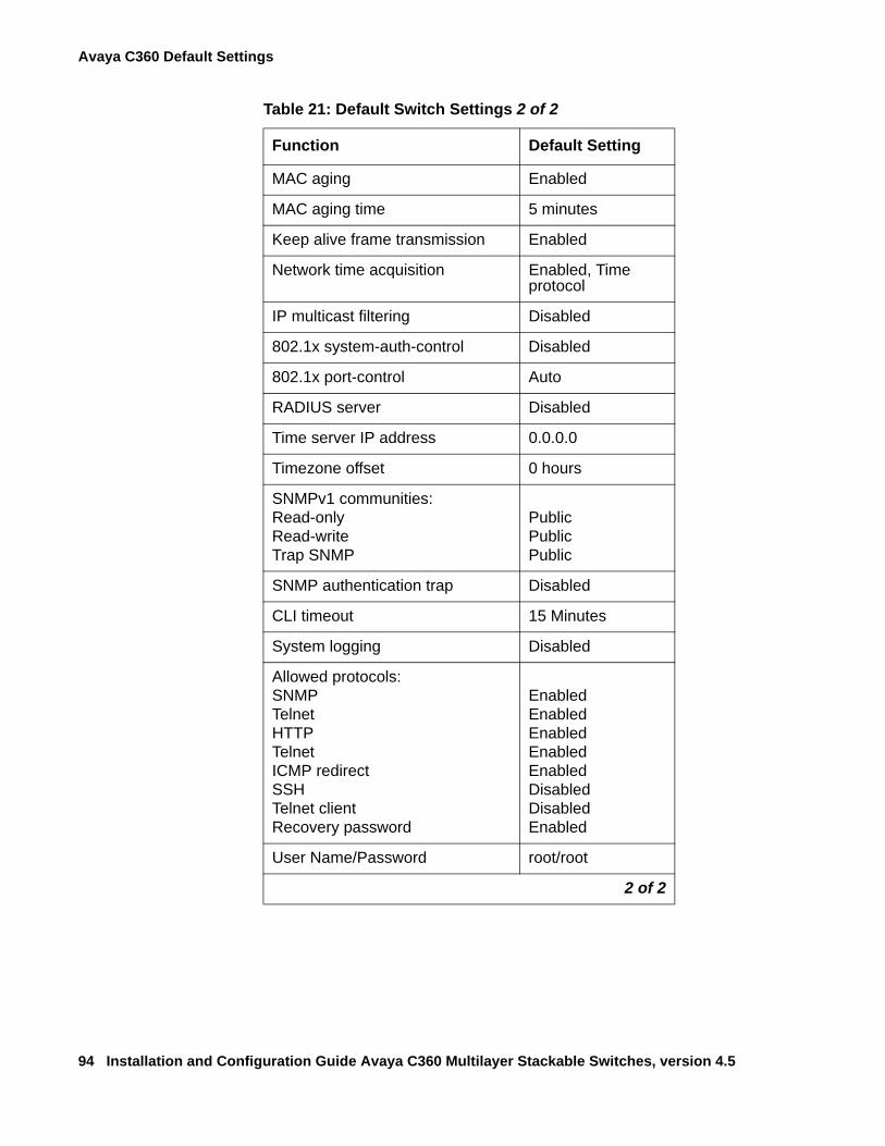
Avaya C360 Default Settings
94 Installation and Configuration Guide Avaya C360 Multilayer Stackable Switches, version 4.5
MAC aging Enabled
MAC aging time 5 minutes
Keep alive frame transmission Enabled
Network time acquisition Enabled, Time protocol
IP multicast filtering Disabled
802.1x system-auth-control Disabled
802.1x port-control Auto
RADIUS server Disabled
Time server IP address 0.0.0.0
Timezone offset 0 hours
SNMPv1 communities:Read-only Read-write Trap SNMP
PublicPublicPublic
SNMP authentication trap Disabled
CLI timeout 15 Minutes
System logging Disabled
Allowed protocols:SNMPTelnetHTTPTelnetICMP redirectSSHTelnet clientRecovery password
EnabledEnabledEnabledEnabledEnabledDisabledDisabledEnabled
User Name/Password root/root
Table 21: Default Switch Settings 2 of 2
Function Default Setting
2 of 2
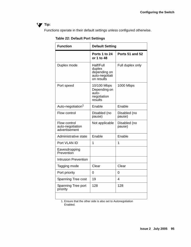
Configuring the Switch
Issue 2 July 2005 95
Tip:Tip: Functions operate in their default settings unless configured otherwise.
Table 22: Default Port Settings
Function Default Setting
Ports 1 to 24 or 1 to 48
Ports 51 and 52
Duplex mode Half/Full duplex depending on auto-negotiation results
Full duplex only
Port speed 10/100 MbpsDepending on auto- negotiation results
1000 Mbps
Auto-negotiation1
1. Ensure that the other side is also set to Autonegotiation Enabled.
Enable Enable
Flow control Disabled (no pause)
Disabled (no pause)
Flow control auto-negotiation advertisement
Not applicable Disabled (no pause)
Administrative state Enable Enable
Port VLAN ID 1 1
Eavesdropping Prevention
Intrusion Prevention
Tagging mode Clear Clear
Port priority 0 0
Spanning Tree cost 19 4
Spanning Tree port priority
128 128

Avaya C360 Default Settings
96 Installation and Configuration Guide Avaya C360 Multilayer Stackable Switches, version 4.5
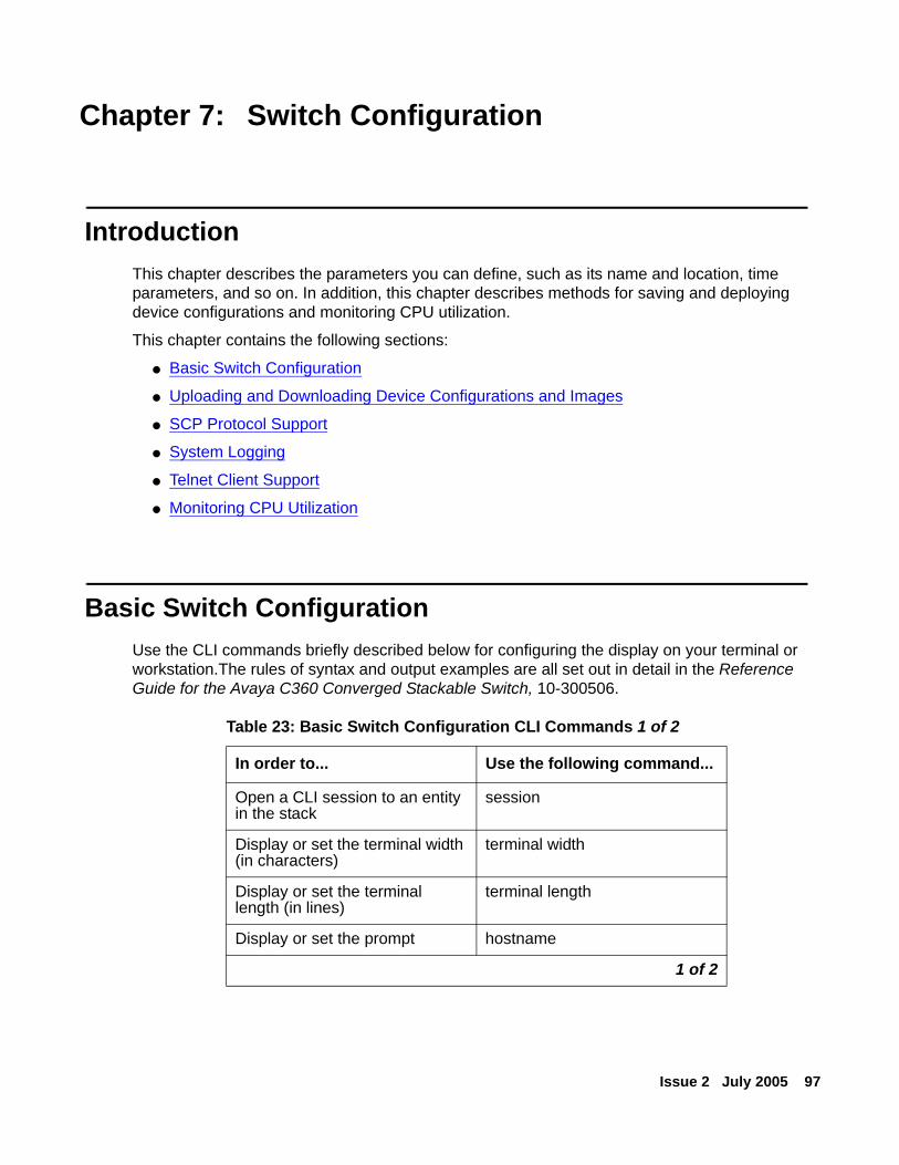
Issue 2 July 2005 97
Chapter 7: Switch Configuration
IntroductionThis chapter describes the parameters you can define, such as its name and location, time parameters, and so on. In addition, this chapter describes methods for saving and deploying device configurations and monitoring CPU utilization.
This chapter contains the following sections:
● Basic Switch Configuration
● Uploading and Downloading Device Configurations and Images
● SCP Protocol Support
● System Logging
● Telnet Client Support
● Monitoring CPU Utilization
Basic Switch ConfigurationUse the CLI commands briefly described below for configuring the display on your terminal or workstation.The rules of syntax and output examples are all set out in detail in the Reference Guide for the Avaya C360 Converged Stackable Switch, 10-300506.
Table 23: Basic Switch Configuration CLI Commands 1 of 2
In order to... Use the following command...
Open a CLI session to an entity in the stack
session
Display or set the terminal width (in characters)
terminal width
Display or set the terminal length (in lines)
terminal length
Display or set the prompt hostname
1 of 2
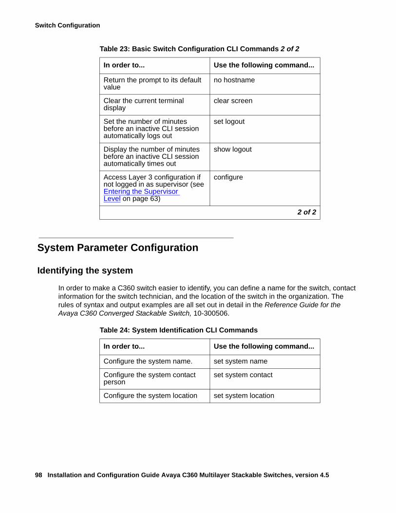
Switch Configuration
98 Installation and Configuration Guide Avaya C360 Multilayer Stackable Switches, version 4.5
System Parameter Configuration
Identifying the system
In order to make a C360 switch easier to identify, you can define a name for the switch, contact information for the switch technician, and the location of the switch in the organization. The rules of syntax and output examples are all set out in detail in the Reference Guide for the Avaya C360 Converged Stackable Switch, 10-300506.
Return the prompt to its default value
no hostname
Clear the current terminal display
clear screen
Set the number of minutes before an inactive CLI session automatically logs out
set logout
Display the number of minutes before an inactive CLI session automatically times out
show logout
Access Layer 3 configuration if not logged in as supervisor (see Entering the Supervisor Level on page 63)
configure
Table 23: Basic Switch Configuration CLI Commands 2 of 2
In order to... Use the following command...
2 of 2
Table 24: System Identification CLI Commands
In order to... Use the following command...
Configure the system name. set system name
Configure the system contact person
set system contact
Configure the system location set system location
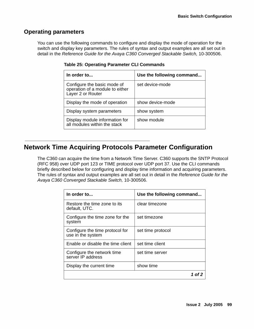
Basic Switch Configuration
Issue 2 July 2005 99
Operating parameters
You can use the following commands to configure and display the mode of operation for the switch and display key parameters. The rules of syntax and output examples are all set out in detail in the Reference Guide for the Avaya C360 Converged Stackable Switch, 10-300506.
Network Time Acquiring Protocols Parameter ConfigurationThe C360 can acquire the time from a Network Time Server. C360 supports the SNTP Protocol (RFC 958) over UDP port 123 or TIME protocol over UDP port 37. Use the CLI commands briefly described below for configuring and display time information and acquiring parameters. The rules of syntax and output examples are all set out in detail in the Reference Guide for the Avaya C360 Converged Stackable Switch, 10-300506.
Table 25: Operating Parameter CLI Commands
In order to... Use the following command...
Configure the basic mode of operation of a module to either Layer 2 or Router
set device-mode
Display the mode of operation show device-mode
Display system parameters show system
Display module information for all modules within the stack
show module
In order to... Use the following command...
Restore the time zone to its default, UTC.
clear timezone
Configure the time zone for the system
set timezone
Configure the time protocol for use in the system
set time protocol
Enable or disable the time client set time client
Configure the network time server IP address
set time server
Display the current time show time
1 of 2
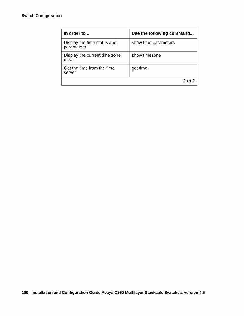
Switch Configuration
100 Installation and Configuration Guide Avaya C360 Multilayer Stackable Switches, version 4.5
Display the time status and parameters
show time parameters
Display the current time zone offset
show timezone
Get the time from the time server
get time
In order to... Use the following command...
2 of 2
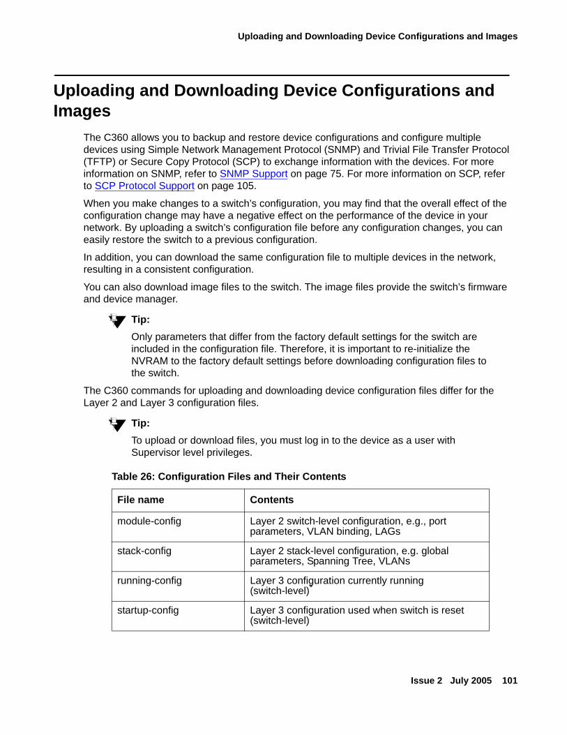
Uploading and Downloading Device Configurations and Images
Issue 2 July 2005 101
Uploading and Downloading Device Configurations and Images
The C360 allows you to backup and restore device configurations and configure multiple devices using Simple Network Management Protocol (SNMP) and Trivial File Transfer Protocol (TFTP) or Secure Copy Protocol (SCP) to exchange information with the devices. For more information on SNMP, refer to SNMP Support on page 75. For more information on SCP, refer to SCP Protocol Support on page 105.
When you make changes to a switch’s configuration, you may find that the overall effect of the configuration change may have a negative effect on the performance of the device in your network. By uploading a switch’s configuration file before any configuration changes, you can easily restore the switch to a previous configuration.
In addition, you can download the same configuration file to multiple devices in the network, resulting in a consistent configuration.
You can also download image files to the switch. The image files provide the switch’s firmware and device manager.
Tip:Tip: Only parameters that differ from the factory default settings for the switch are
included in the configuration file. Therefore, it is important to re-initialize the NVRAM to the factory default settings before downloading configuration files to the switch.
The C360 commands for uploading and downloading device configuration files differ for the Layer 2 and Layer 3 configuration files.
Tip:Tip: To upload or download files, you must log in to the device as a user with
Supervisor level privileges.
Table 26: Configuration Files and Their Contents
File name Contents
module-config Layer 2 switch-level configuration, e.g., port parameters, VLAN binding, LAGs
stack-config Layer 2 stack-level configuration, e.g. global parameters, Spanning Tree, VLANs
running-config Layer 3 configuration currently running (switch-level)*
startup-config Layer 3 configuration used when switch is reset (switch-level)
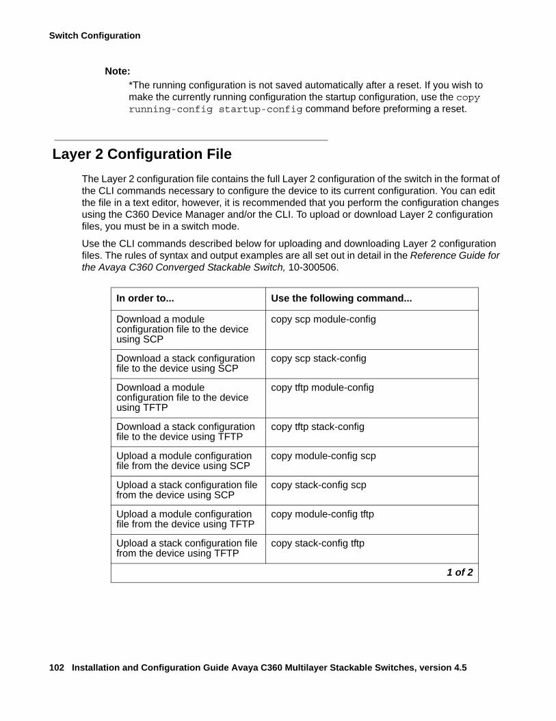
Switch Configuration
102 Installation and Configuration Guide Avaya C360 Multilayer Stackable Switches, version 4.5
Note:Note: *The running configuration is not saved automatically after a reset. If you wish to
make the currently running configuration the startup configuration, use the copy running-config startup-config command before preforming a reset.
Layer 2 Configuration FileThe Layer 2 configuration file contains the full Layer 2 configuration of the switch in the format of the CLI commands necessary to configure the device to its current configuration. You can edit the file in a text editor, however, it is recommended that you perform the configuration changes using the C360 Device Manager and/or the CLI. To upload or download Layer 2 configuration files, you must be in a switch mode.
Use the CLI commands described below for uploading and downloading Layer 2 configuration files. The rules of syntax and output examples are all set out in detail in the Reference Guide for the Avaya C360 Converged Stackable Switch, 10-300506.
In order to... Use the following command...
Download a module configuration file to the device using SCP
copy scp module-config
Download a stack configuration file to the device using SCP
copy scp stack-config
Download a module configuration file to the device using TFTP
copy tftp module-config
Download a stack configuration file to the device using TFTP
copy tftp stack-config
Upload a module configuration file from the device using SCP
copy module-config scp
Upload a stack configuration file from the device using SCP
copy stack-config scp
Upload a module configuration file from the device using TFTP
copy module-config tftp
Upload a stack configuration file from the device using TFTP
copy stack-config tftp
1 of 2
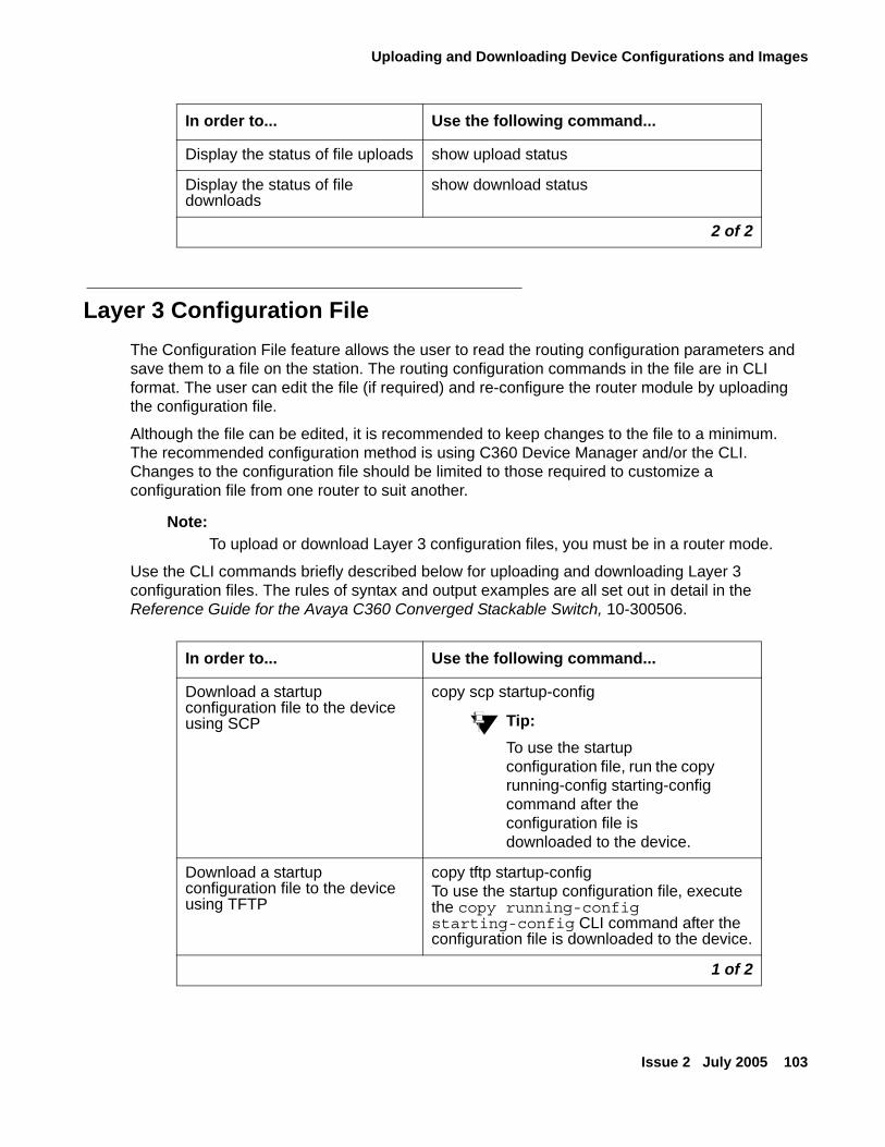
Uploading and Downloading Device Configurations and Images
Issue 2 July 2005 103
Layer 3 Configuration FileThe Configuration File feature allows the user to read the routing configuration parameters and save them to a file on the station. The routing configuration commands in the file are in CLI format. The user can edit the file (if required) and re-configure the router module by uploading the configuration file.
Although the file can be edited, it is recommended to keep changes to the file to a minimum. The recommended configuration method is using C360 Device Manager and/or the CLI. Changes to the configuration file should be limited to those required to customize a configuration file from one router to suit another.
Note:Note: To upload or download Layer 3 configuration files, you must be in a router mode.
Use the CLI commands briefly described below for uploading and downloading Layer 3 configuration files. The rules of syntax and output examples are all set out in detail in the Reference Guide for the Avaya C360 Converged Stackable Switch, 10-300506.
Display the status of file uploads show upload status
Display the status of file downloads
show download status
In order to... Use the following command...
2 of 2
In order to... Use the following command...
Download a startup configuration file to the device using SCP
copy scp startup-config
Tip:Tip: To use the startup
configuration file, run the copy running-config starting-config command after the configuration file is downloaded to the device.
Download a startup configuration file to the device using TFTP
copy tftp startup-configTo use the startup configuration file, execute the copy running-config starting-config CLI command after the configuration file is downloaded to the device.
1 of 2
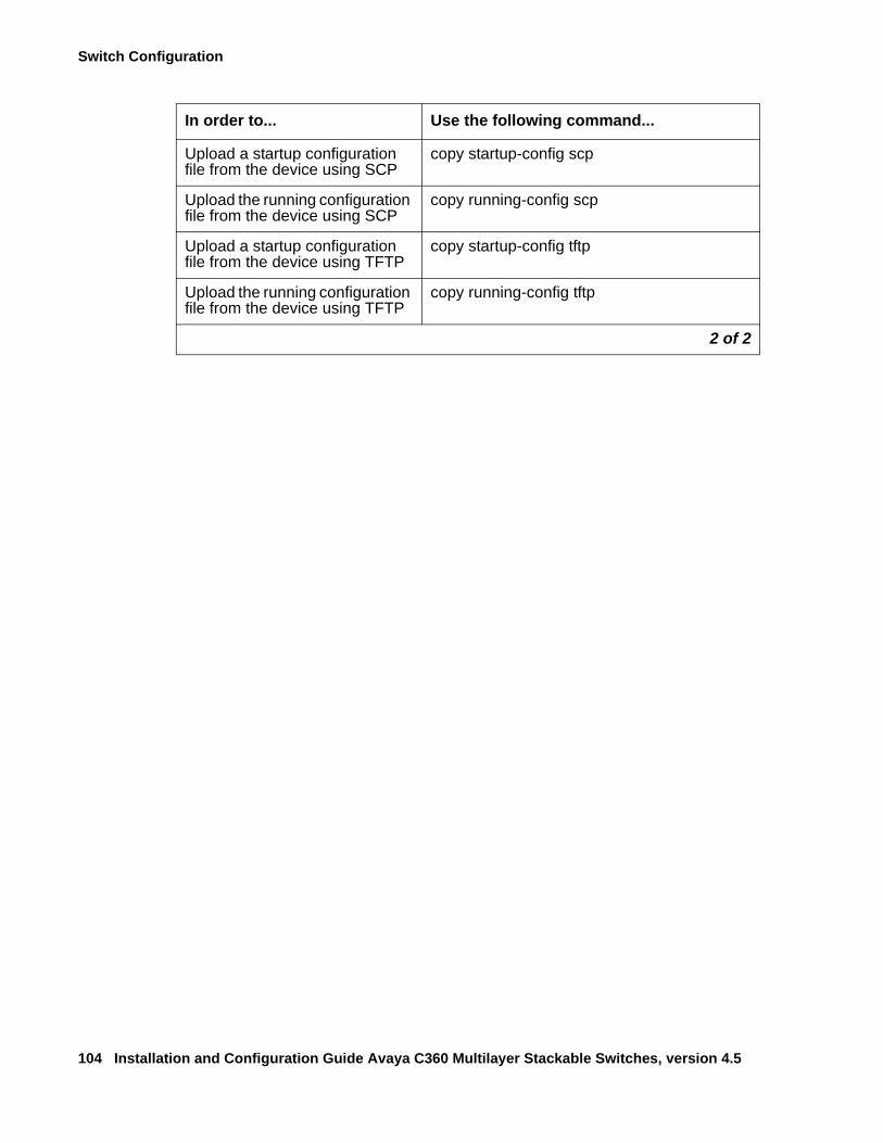
Switch Configuration
104 Installation and Configuration Guide Avaya C360 Multilayer Stackable Switches, version 4.5
Upload a startup configuration file from the device using SCP
copy startup-config scp
Upload the running configuration file from the device using SCP
copy running-config scp
Upload a startup configuration file from the device using TFTP
copy startup-config tftp
Upload the running configuration file from the device using TFTP
copy running-config tftp
In order to... Use the following command...
2 of 2
SCP Protocol Support
Issue 2 July 2005 105
SCP Protocol SupportIn addition to data transfer via an SSH session, the SSH protocol is also used to support SCP for secure file transfer. When using SCP, the C360 is the client, and an SCP server must be installed on the management station. After defining users on the SCP server, the device acts as an SCP client.
The procedure described in the Introduction to SSH on page 68 is used with the roles of the C360 and the client computer reversed.
To accomplish secured transfers, a C360 launches a local SSH client via the CLI in order to establish a secured channel to the secured file server. The C360 authenticates itself to the server by providing a user name and password. With a Windows-based SSH server (WinSSHD), the user name provided must be a defined user on the Windows machine with read/write privileges. The files transferred via SCP are saved in the "C:\Documents and Settings\username" directory.
The network element performs file transfer in unattended mode.
! SECURITY ALERT:SECURITY ALERT: The C360 doesn't block SCP traffic from users not on the allowed managers list,
because it is the SSH client. In addition, the C360 doesn't prompt the user to accept the Server’s fingerprint nor warn the user if the fingerprint from an IP address has changed.
For information on SCP file transfer commands, refer to Uploading and Downloading Device Configurations and Images on page 101.
Switch Configuration
106 Installation and Configuration Guide Avaya C360 Multilayer Stackable Switches, version 4.5
System Logging
System Logging IntroductionThe C360 System Logging feature is capable of storing system messages on a device, outputting messages to the CLI console, Telnet session, or SSH session, and reporting remotely to a Syslog server. System Logging is an important tool used for routine maintenance, auditing, and monitoring access to the device.
The components of System Logging include:
● Logging Messages
● Sinks
● Message Facilities
System Logging Messages
System logging messages provide the following information:
● Module ID – The number of the module from which the message originated.
● Event Time – The time the event occurred. The Event Time is included only if a time server is configured for the device.
● Message Facility – The software sub-system from which the message originated.
● Severity Level – The severity level of the message. Severity levels from the highest severity to the lowest include: Emergency, Alert, Critical, Error, Warning, Notification, Informational, Debug
● Message Content – A description of the event.
In order to reduce the number of collected and transmitted messages, filtering options should be used. The filtering options are based on message classification by Message Facility and severity. For a specified sink, you can define the threshold severity for messages output by each Message Facility. Messages with a severity lower than the defined threshold are not sent to the specified sink.
In addition, the session sink filters the messages using the access level of the user. Only messages the user is permitted to access are output to the console or Telnet/SSH session.
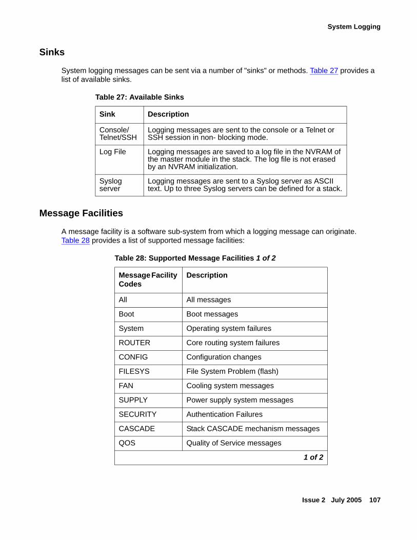
System Logging
Issue 2 July 2005 107
Sinks
System logging messages can be sent via a number of "sinks" or methods. Table 27 provides a list of available sinks.
Message Facilities
A message facility is a software sub-system from which a logging message can originate. Table 28 provides a list of supported message facilities:
Table 27: Available Sinks
Sink Description
Console/Telnet/SSH
Logging messages are sent to the console or a Telnet or SSH session in non- blocking mode.
Log File Logging messages are saved to a log file in the NVRAM of the master module in the stack. The log file is not erased by an NVRAM initialization.
Syslog server
Logging messages are sent to a Syslog server as ASCII text. Up to three Syslog servers can be defined for a stack.
Table 28: Supported Message Facilities 1 of 2
Message Facility Codes
Description
All All messages
Boot Boot messages
System Operating system failures
ROUTER Core routing system failures
CONFIG Configuration changes
FILESYS File System Problem (flash)
FAN Cooling system messages
SUPPLY Power supply system messages
SECURITY Authentication Failures
CASCADE Stack CASCADE mechanism messages
QOS Quality of Service messages
1 of 2
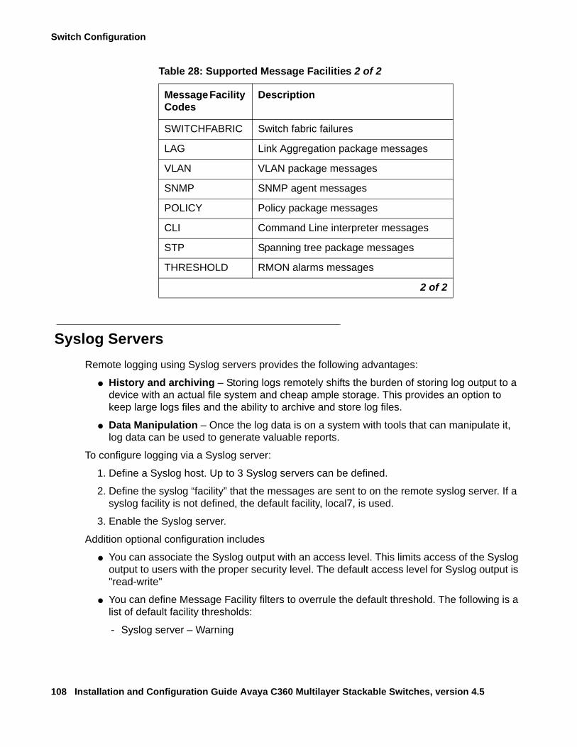
Switch Configuration
108 Installation and Configuration Guide Avaya C360 Multilayer Stackable Switches, version 4.5
Syslog ServersRemote logging using Syslog servers provides the following advantages:
● History and archiving – Storing logs remotely shifts the burden of storing log output to a device with an actual file system and cheap ample storage. This provides an option to keep large logs files and the ability to archive and store log files.
● Data Manipulation – Once the log data is on a system with tools that can manipulate it, log data can be used to generate valuable reports.
To configure logging via a Syslog server:
1. Define a Syslog host. Up to 3 Syslog servers can be defined.
2. Define the syslog “facility” that the messages are sent to on the remote syslog server. If a syslog facility is not defined, the default facility, local7, is used.
3. Enable the Syslog server.
Addition optional configuration includes
● You can associate the Syslog output with an access level. This limits access of the Syslog output to users with the proper security level. The default access level for Syslog output is "read-write"
● You can define Message Facility filters to overrule the default threshold. The following is a list of default facility thresholds:
- Syslog server – Warning
SWITCHFABRIC Switch fabric failures
LAG Link Aggregation package messages
VLAN VLAN package messages
SNMP SNMP agent messages
POLICY Policy package messages
CLI Command Line interpreter messages
STP Spanning tree package messages
THRESHOLD RMON alarms messages
Table 28: Supported Message Facilities 2 of 2
Message Facility Codes
Description
2 of 2
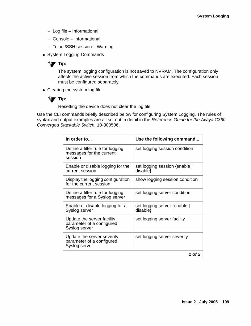
System Logging
Issue 2 July 2005 109
- Log file – Informational
- Console – Informational
- Telnet/SSH session – Warning
● System Logging Commands
Tip:Tip: The system logging configuration is not saved to NVRAM. The configuration only
affects the active session from which the commands are executed. Each session must be configured separately.
● Clearing the system log file.
Tip:Tip: Resetting the device does not clear the log file.
Use the CLI commands briefly described below for configuring System Logging. The rules of syntax and output examples are all set out in detail in the Reference Guide for the Avaya C360 Converged Stackable Switch, 10-300506.
In order to... Use the following command...
Define a filter rule for logging messages for the current session
set logging session condition
Enable or disable logging for the current session
set logging session {enable | disable}
Display the logging configuration for the current session
show logging session condition
Define a filter rule for logging messages for a Syslog server
set logging server condition
Enable or disable logging for a Syslog server
set logging server {enable | disable}
Update the server facility parameter of a configured Syslog server
set logging server facility
Update the server severity parameter of a configured Syslog server
set logging server severity
1 of 2
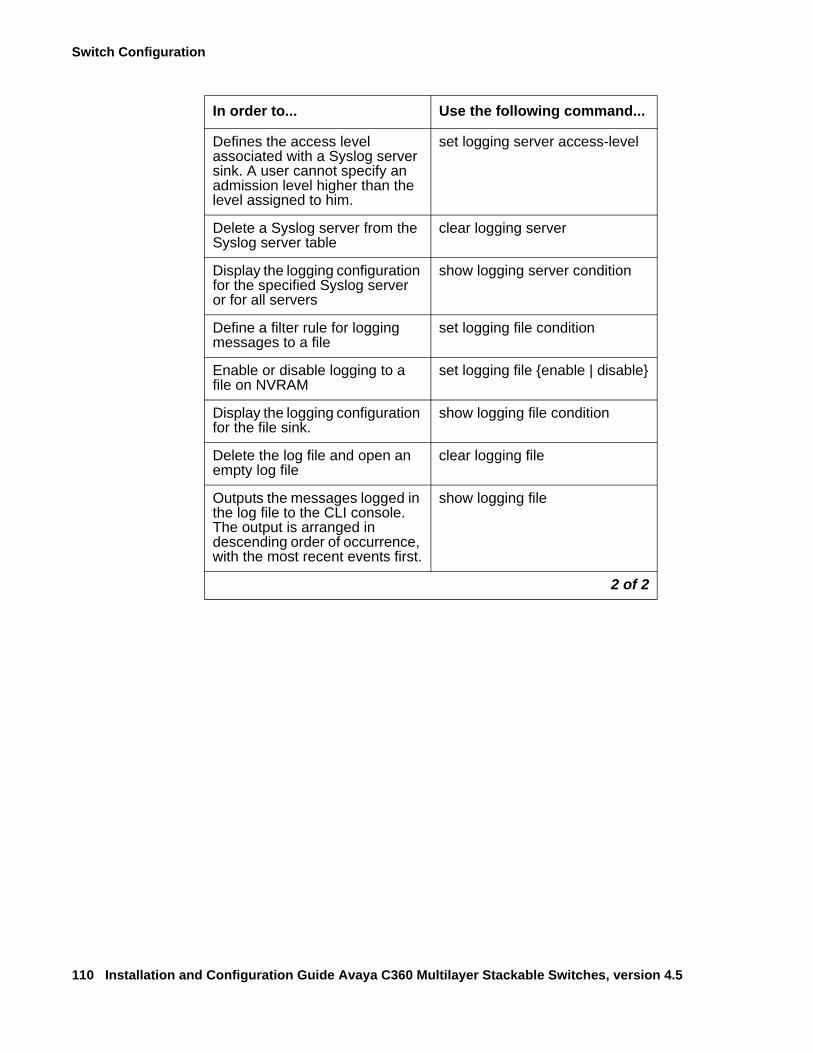
Switch Configuration
110 Installation and Configuration Guide Avaya C360 Multilayer Stackable Switches, version 4.5
Defines the access level associated with a Syslog server sink. A user cannot specify an admission level higher than the level assigned to him.
set logging server access-level
Delete a Syslog server from the Syslog server table
clear logging server
Display the logging configuration for the specified Syslog server or for all servers
show logging server condition
Define a filter rule for logging messages to a file
set logging file condition
Enable or disable logging to a file on NVRAM
set logging file {enable | disable}
Display the logging configuration for the file sink.
show logging file condition
Delete the log file and open an empty log file
clear logging file
Outputs the messages logged in the log file to the CLI console. The output is arranged in descending order of occurrence, with the most recent events first.
show logging file
In order to... Use the following command...
2 of 2
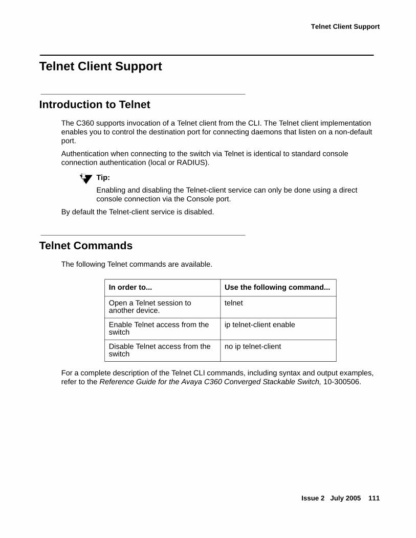
Telnet Client Support
Issue 2 July 2005 111
Telnet Client Support
Introduction to TelnetThe C360 supports invocation of a Telnet client from the CLI. The Telnet client implementation enables you to control the destination port for connecting daemons that listen on a non-default port.
Authentication when connecting to the switch via Telnet is identical to standard console connection authentication (local or RADIUS).
Tip:Tip: Enabling and disabling the Telnet-client service can only be done using a direct
console connection via the Console port.
By default the Telnet-client service is disabled.
Telnet Commands The following Telnet commands are available.
For a complete description of the Telnet CLI commands, including syntax and output examples, refer to the Reference Guide for the Avaya C360 Converged Stackable Switch, 10-300506.
In order to... Use the following command...
Open a Telnet session to another device.
telnet
Enable Telnet access from the switch
ip telnet-client enable
Disable Telnet access from the switch
no ip telnet-client
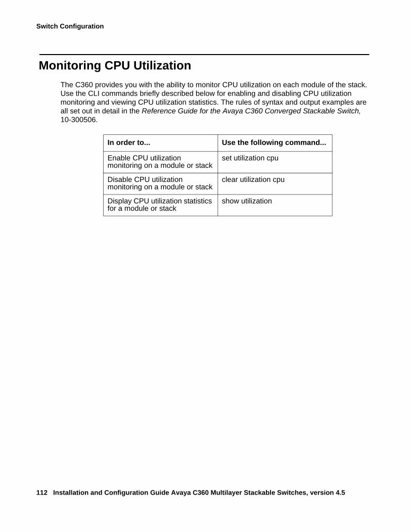
Switch Configuration
112 Installation and Configuration Guide Avaya C360 Multilayer Stackable Switches, version 4.5
Monitoring CPU UtilizationThe C360 provides you with the ability to monitor CPU utilization on each module of the stack. Use the CLI commands briefly described below for enabling and disabling CPU utilization monitoring and viewing CPU utilization statistics. The rules of syntax and output examples are all set out in detail in the Reference Guide for the Avaya C360 Converged Stackable Switch, 10-300506.
In order to... Use the following command...
Enable CPU utilization monitoring on a module or stack
set utilization cpu
Disable CPU utilization monitoring on a module or stack
clear utilization cpu
Display CPU utilization statistics for a module or stack
show utilization
Issue 2 July 2005 113
Chapter 8: Avaya C360 Layer 2 Features
This section describes the C360 Layer 2 features. It provides the basic procedures for configuring the C360 for Layer 2 operation.
The C360 supports a range of Layer 2 features. Each feature has CLI commands associated with it. These commands are used to configure, operate, or monitor switch activity for each of the Layer 2 features.
This section of the C360 Installation and Maintenance Guide explains each of the features. Specifically, the topics discussed here include:
● Ethernet
● VLANs
● IEEE 802.1x (Port Based Network Access Control)
● Spanning Tree Protocol
● MAC Security
● LAG (Link Aggregate Group)
● Port Redundancy
● IP Multicast Filtering
● RMON
● SMON
● Port Mirroring
● Weighted Queuing
● LLDP Server
Avaya C360 Layer 2 Features
114 Installation and Configuration Guide Avaya C360 Multilayer Stackable Switches, version 4.5
EthernetEthernet is one of the most widely implemented LAN standards. It uses the Carrier Sense Multiple Access with Collision Detection (CSMA/CD) access method to handle simultaneous demands. CSMA/CD is a multi-user network allocation procedure in which every station can receive the transmissions of every other station. Each station waits for the network to be idle before transmitting and each station can detect collisions by other stations.
The first version of Ethernet supported data transfer rates of 10 Mbps, and is therefore known as 10BASE-T (over copper) or 10BASE-FX (over fiber).
Fast EthernetFast Ethernet is a newer version of Ethernet, supporting data transfer rates of 100 Mbps. Fast Ethernet is sufficiently similar to Ethernet to support the use of most existing Ethernet applications and network management tools. The adoption of Fast Ethernet is as 100BASE-T (over copper) or 100BASE-FX (over fiber).
Fast Ethernet is standardized as IEEE 802.3u.
Gigabit EthernetGigabit Ethernet supports data rates of 1 Gbps. Gigabit Ethernet standards are 1000BASE-T (over copper) or 1000BASE-ELX, 1000BASE-LX and 1000BASE-SX (over fiber).
Gigabit Ethernet is standardized as IEEE 802.3z.
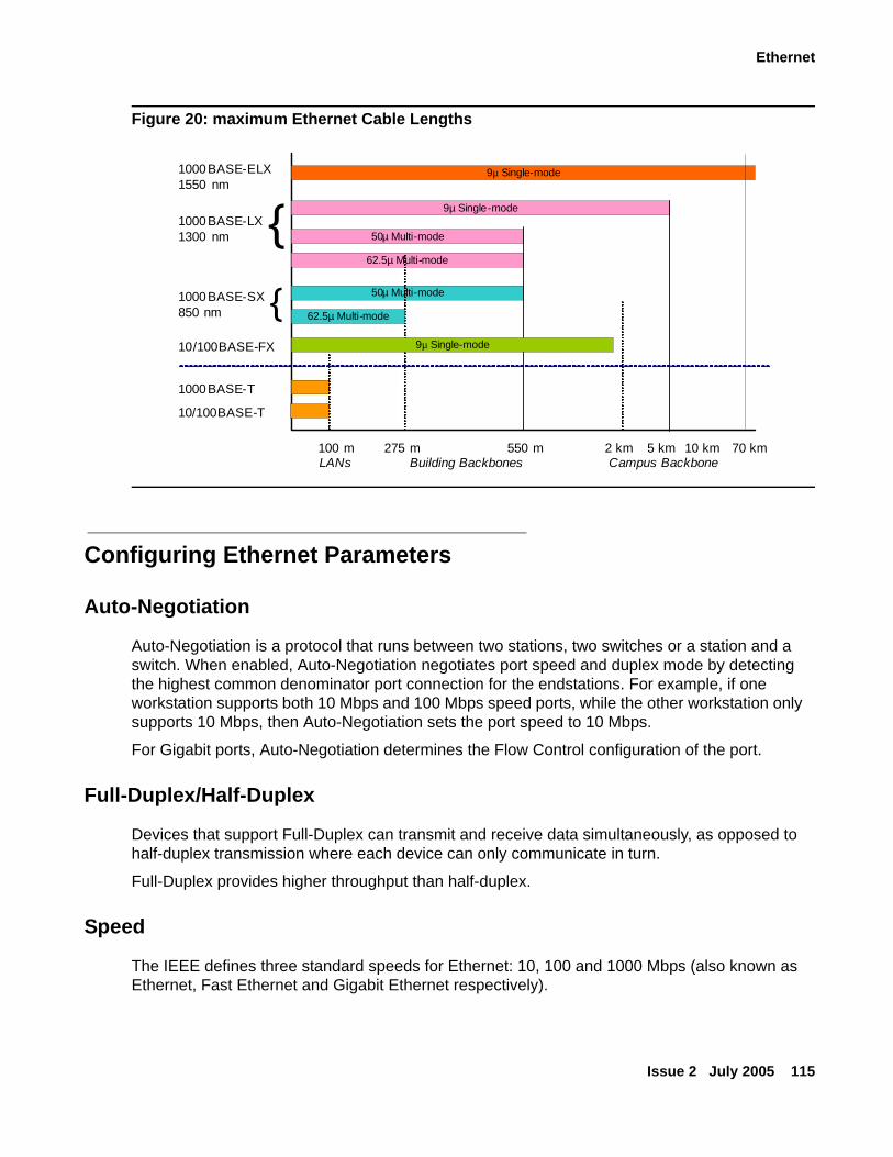
Ethernet
Issue 2 July 2005 115
Figure 20: maximum Ethernet Cable Lengths
Configuring Ethernet Parameters
Auto-Negotiation
Auto-Negotiation is a protocol that runs between two stations, two switches or a station and a switch. When enabled, Auto-Negotiation negotiates port speed and duplex mode by detecting the highest common denominator port connection for the endstations. For example, if one workstation supports both 10 Mbps and 100 Mbps speed ports, while the other workstation only supports 10 Mbps, then Auto-Negotiation sets the port speed to 10 Mbps.
For Gigabit ports, Auto-Negotiation determines the Flow Control configuration of the port.
Full-Duplex/Half-Duplex
Devices that support Full-Duplex can transmit and receive data simultaneously, as opposed to half-duplex transmission where each device can only communicate in turn.
Full-Duplex provides higher throughput than half-duplex.
Speed
The IEEE defines three standard speeds for Ethernet: 10, 100 and 1000 Mbps (also known as Ethernet, Fast Ethernet and Gigabit Ethernet respectively).
9µ Single-mode
9µ Single-mode
50µ Multi-mode
62.5µ Multi-mode
50µ Multi-mode
62.5µ Multi-mode
9µ Single-mode
1000BASE-ELX1550 nm
1000BASE-LX1300 nm
1000BASE-SX850 nm
10/100BASE-FX
275 m 550 m 5 km2 km 10 km 70 kmBuilding Backbones Campus Backbone
{{
1000BASE-T
100 mLANs
10/100BASE-T
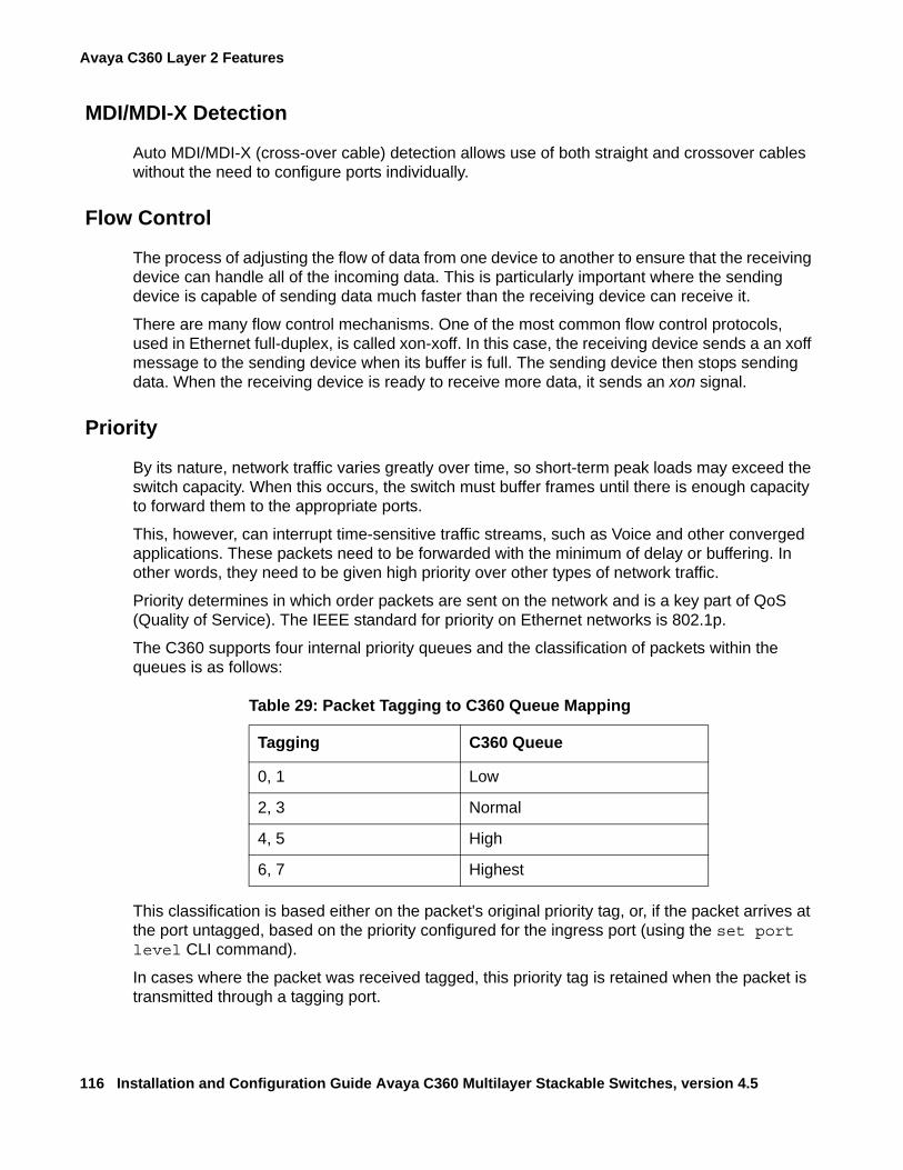
Avaya C360 Layer 2 Features
116 Installation and Configuration Guide Avaya C360 Multilayer Stackable Switches, version 4.5
MDI/MDI-X Detection
Auto MDI/MDI-X (cross-over cable) detection allows use of both straight and crossover cables without the need to configure ports individually.
Flow Control
The process of adjusting the flow of data from one device to another to ensure that the receiving device can handle all of the incoming data. This is particularly important where the sending device is capable of sending data much faster than the receiving device can receive it.
There are many flow control mechanisms. One of the most common flow control protocols, used in Ethernet full-duplex, is called xon-xoff. In this case, the receiving device sends a an xoff message to the sending device when its buffer is full. The sending device then stops sending data. When the receiving device is ready to receive more data, it sends an xon signal.
Priority
By its nature, network traffic varies greatly over time, so short-term peak loads may exceed the switch capacity. When this occurs, the switch must buffer frames until there is enough capacity to forward them to the appropriate ports.
This, however, can interrupt time-sensitive traffic streams, such as Voice and other converged applications. These packets need to be forwarded with the minimum of delay or buffering. In other words, they need to be given high priority over other types of network traffic.
Priority determines in which order packets are sent on the network and is a key part of QoS (Quality of Service). The IEEE standard for priority on Ethernet networks is 802.1p.
The C360 supports four internal priority queues and the classification of packets within the queues is as follows:
This classification is based either on the packet's original priority tag, or, if the packet arrives at the port untagged, based on the priority configured for the ingress port (using the set port level CLI command).
In cases where the packet was received tagged, this priority tag is retained when the packet is transmitted through a tagging port.
Table 29: Packet Tagging to C360 Queue Mapping
Tagging C360 Queue
0, 1 Low
2, 3 Normal
4, 5 High
6, 7 Highest
Ethernet
Issue 2 July 2005 117
In cases where the priority is assigned based on the ingress priority of the port, then on an egress tagging port the packet will tagged according to the ingress port priority value configured by the set port level CLI command.
MAC Address
The MAC address is a unique 48-bit value associated with any network adapter. MAC addresses are also known as hardware addresses or physical addresses. They uniquely identify an adapter on a LAN.
MAC addresses are 12-digit hexadecimal numbers (48 bits in length). By convention, MAC addresses are usually written in one of the following two formats:
● MM:MM:MM:SS:SS:SS
● MM-MM-MM-SS-SS-SS
The first half of a MAC address contains the ID number of the device manufacturer. These IDs are regulated by an Internet standards body. The second half of a MAC address represents the serial number assigned to the device by the manufacturer.
CAM Table
The CAM Table contains a mapping of learned MAC addresses to ports and VLANs. The switch checks forwarding requests against the addresses contained in the CAM Table:
● If the MAC address appears in the CAM Table, the packet is forwarded to the appropriate port.
● If the MAC address does not appear in the CAM Table, or the MAC Address mapping has changed, the frame is duplicated and copied to all the ports on the same VLAN. Once a reply is received, the CAM table is updated with the new address/VLAN port mapping.
MAC Aging
The MAC Aging feature allows the user to configure a time interval after which unused entries in the MAC Table will be deleted.
Following is the description of configuration of the C360 for the MAC Aging functionality.
● MAC Aging is configured on the stack level.
● MAC Aging can be globally enabled/disabled using the set mac-aging command.
● "mac-aging-time" is set in minutes:
- Default = five minutes
- Minimum time = one minute; maximum time = 3600 min.
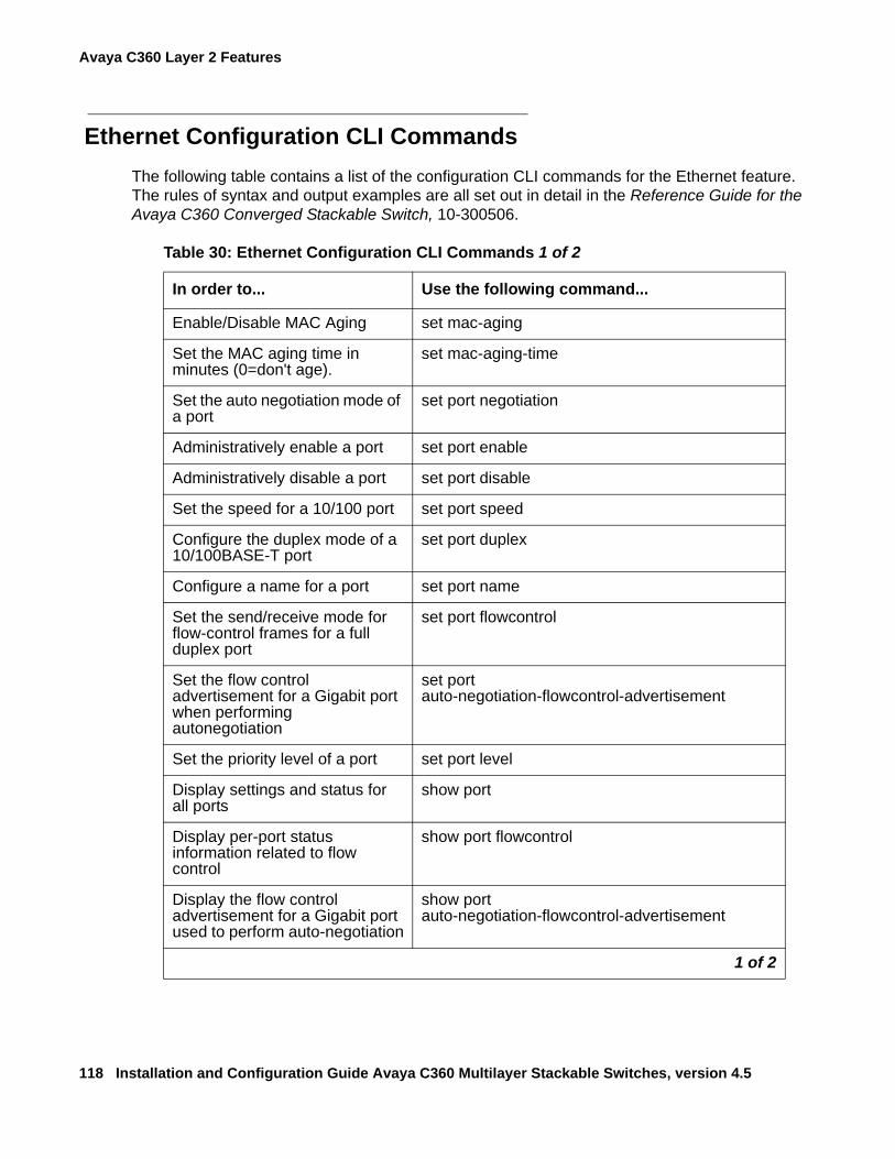
Avaya C360 Layer 2 Features
118 Installation and Configuration Guide Avaya C360 Multilayer Stackable Switches, version 4.5
Ethernet Configuration CLI CommandsThe following table contains a list of the configuration CLI commands for the Ethernet feature. The rules of syntax and output examples are all set out in detail in the Reference Guide for the Avaya C360 Converged Stackable Switch, 10-300506.
Table 30: Ethernet Configuration CLI Commands 1 of 2
In order to... Use the following command...
Enable/Disable MAC Aging set mac-aging
Set the MAC aging time in minutes (0=don't age).
set mac-aging-time
Set the auto negotiation mode of a port
set port negotiation
Administratively enable a port set port enable
Administratively disable a port set port disable
Set the speed for a 10/100 port set port speed
Configure the duplex mode of a 10/100BASE-T port
set port duplex
Configure a name for a port set port name
Set the send/receive mode for flow-control frames for a full duplex port
set port flowcontrol
Set the flow control advertisement for a Gigabit port when performing autonegotiation
set port auto-negotiation-flowcontrol-advertisement
Set the priority level of a port set port level
Display settings and status for all ports
show port
Display per-port status information related to flow control
show port flowcontrol
Display the flow control advertisement for a Gigabit port used to perform auto-negotiation
show port auto-negotiation-flowcontrol-advertisement
1 of 2
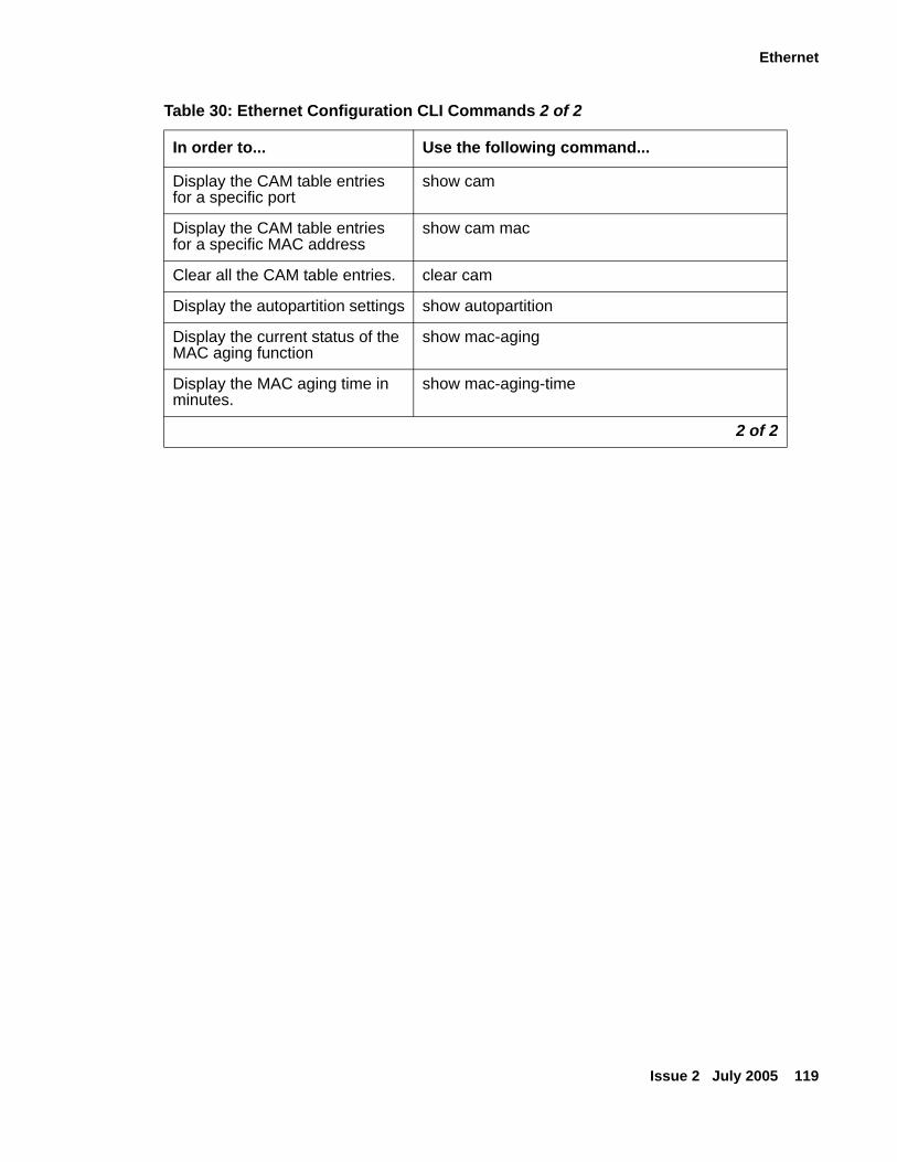
Ethernet
Issue 2 July 2005 119
Display the CAM table entries for a specific port
show cam
Display the CAM table entries for a specific MAC address
show cam mac
Clear all the CAM table entries. clear cam
Display the autopartition settings show autopartition
Display the current status of the MAC aging function
show mac-aging
Display the MAC aging time in minutes.
show mac-aging-time
Table 30: Ethernet Configuration CLI Commands 2 of 2
In order to... Use the following command...
2 of 2
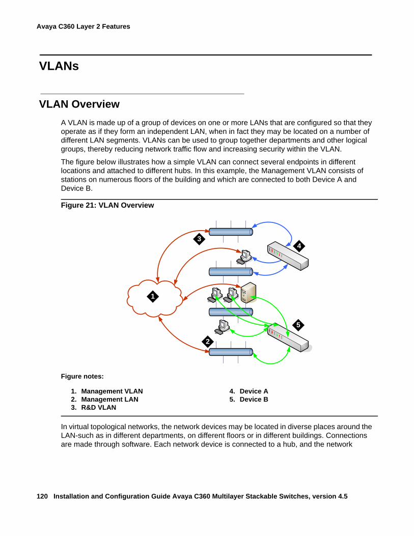
Avaya C360 Layer 2 Features
120 Installation and Configuration Guide Avaya C360 Multilayer Stackable Switches, version 4.5
VLANs
VLAN OverviewA VLAN is made up of a group of devices on one or more LANs that are configured so that they operate as if they form an independent LAN, when in fact they may be located on a number of different LAN segments. VLANs can be used to group together departments and other logical groups, thereby reducing network traffic flow and increasing security within the VLAN.
The figure below illustrates how a simple VLAN can connect several endpoints in different locations and attached to different hubs. In this example, the Management VLAN consists of stations on numerous floors of the building and which are connected to both Device A and Device B.
Figure 21: VLAN Overview
In virtual topological networks, the network devices may be located in diverse places around the LAN-such as in different departments, on different floors or in different buildings. Connections are made through software. Each network device is connected to a hub, and the network
Figure notes:
1. Management VLAN2. Management LAN3. R&D VLAN
4. Device A5. Device B
`
`
`
`1
2
34
5
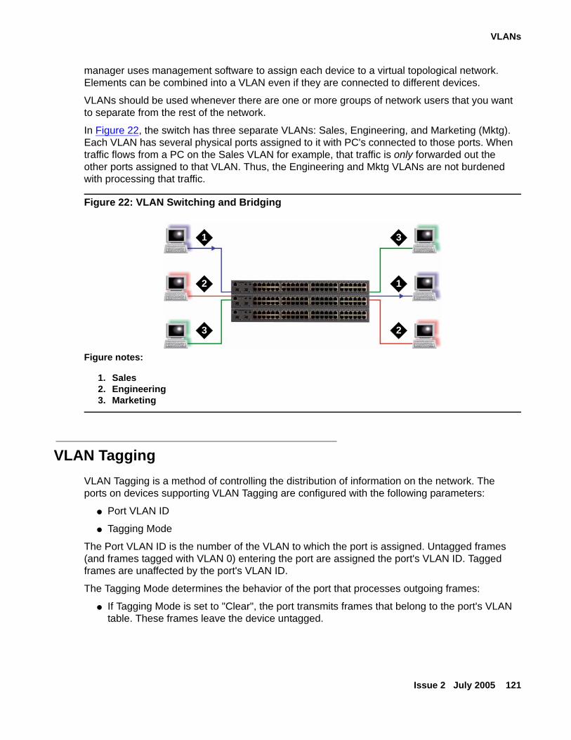
VLANs
Issue 2 July 2005 121
manager uses management software to assign each device to a virtual topological network. Elements can be combined into a VLAN even if they are connected to different devices.
VLANs should be used whenever there are one or more groups of network users that you want to separate from the rest of the network.
In Figure 22, the switch has three separate VLANs: Sales, Engineering, and Marketing (Mktg). Each VLAN has several physical ports assigned to it with PC's connected to those ports. When traffic flows from a PC on the Sales VLAN for example, that traffic is only forwarded out the other ports assigned to that VLAN. Thus, the Engineering and Mktg VLANs are not burdened with processing that traffic.
Figure 22: VLAN Switching and Bridging
VLAN TaggingVLAN Tagging is a method of controlling the distribution of information on the network. The ports on devices supporting VLAN Tagging are configured with the following parameters:
● Port VLAN ID
● Tagging Mode
The Port VLAN ID is the number of the VLAN to which the port is assigned. Untagged frames (and frames tagged with VLAN 0) entering the port are assigned the port's VLAN ID. Tagged frames are unaffected by the port's VLAN ID.
The Tagging Mode determines the behavior of the port that processes outgoing frames:
● If Tagging Mode is set to "Clear", the port transmits frames that belong to the port's VLAN table. These frames leave the device untagged.
Figure notes:
1. Sales2. Engineering3. Marketing
1
2
3
1
2
3
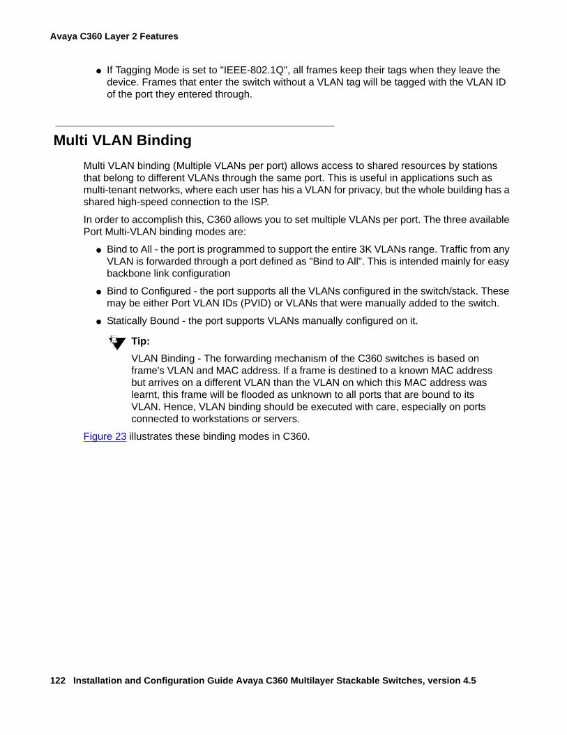
Avaya C360 Layer 2 Features
122 Installation and Configuration Guide Avaya C360 Multilayer Stackable Switches, version 4.5
● If Tagging Mode is set to "IEEE-802.1Q", all frames keep their tags when they leave the device. Frames that enter the switch without a VLAN tag will be tagged with the VLAN ID of the port they entered through.
Multi VLAN BindingMulti VLAN binding (Multiple VLANs per port) allows access to shared resources by stations that belong to different VLANs through the same port. This is useful in applications such as multi-tenant networks, where each user has his a VLAN for privacy, but the whole building has a shared high-speed connection to the ISP.
In order to accomplish this, C360 allows you to set multiple VLANs per port. The three available Port Multi-VLAN binding modes are:
● Bind to All - the port is programmed to support the entire 3K VLANs range. Traffic from any VLAN is forwarded through a port defined as "Bind to All". This is intended mainly for easy backbone link configuration
● Bind to Configured - the port supports all the VLANs configured in the switch/stack. These may be either Port VLAN IDs (PVID) or VLANs that were manually added to the switch.
● Statically Bound - the port supports VLANs manually configured on it.
Tip:Tip: VLAN Binding - The forwarding mechanism of the C360 switches is based on
frame's VLAN and MAC address. If a frame is destined to a known MAC address but arrives on a different VLAN than the VLAN on which this MAC address was learnt, this frame will be flooded as unknown to all ports that are bound to its VLAN. Hence, VLAN binding should be executed with care, especially on ports connected to workstations or servers.
Figure 23 illustrates these binding modes in C360.
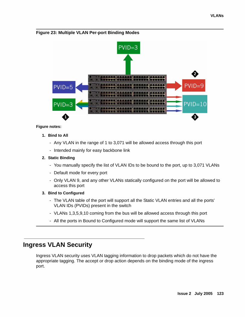
VLANs
Issue 2 July 2005 123
Figure 23: Multiple VLAN Per-port Binding Modes
Ingress VLAN SecurityIngress VLAN security uses VLAN tagging information to drop packets which do not have the appropriate tagging. The accept or drop action depends on the binding mode of the ingress port.
Figure notes:
1. Bind to All
- Any VLAN in the range of 1 to 3,071 will be allowed access through this port
- Intended mainly for easy backbone link
2. Static Binding
- You manually specify the list of VLAN IDs to be bound to the port, up to 3,071 VLANs
- Default mode for every port
- Only VLAN 9, and any other VLANs statically configured on the port will be allowed to access this port
3. Bind to Configured
- The VLAN table of the port will support all the Static VLAN entries and all the ports' VLAN IDs (PVIDs) present in the switch
- VLANs 1,3,5,9,10 coming from the bus will be allowed access through this port
- All the ports in Bound to Configured mode will support the same list of VLANs
2
31
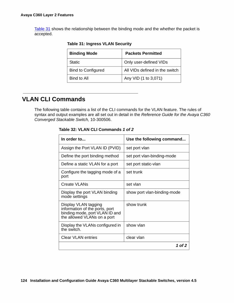
Avaya C360 Layer 2 Features
124 Installation and Configuration Guide Avaya C360 Multilayer Stackable Switches, version 4.5
Table 31 shows the relationship between the binding mode and the whether the packet is accepted.
VLAN CLI CommandsThe following table contains a list of the CLI commands for the VLAN feature. The rules of syntax and output examples are all set out in detail in the Reference Guide for the Avaya C360 Converged Stackable Switch, 10-300506.
Table 31: Ingress VLAN Security
Binding Mode Packets Permitted
Static Only user-defined VIDs
Bind to Configured All VIDs defined in the switch
Bind to All Any VID (1 to 3,071)
Table 32: VLAN CLI Commands 1 of 2
In order to... Use the following command...
Assign the Port VLAN ID (PVID) set port vlan
Define the port binding method set port vlan-binding-mode
Define a static VLAN for a port set port static-vlan
Configure the tagging mode of a port
set trunk
Create VLANs set vlan
Display the port VLAN binding mode settings
show port vlan-binding-mode
Display VLAN tagging information of the ports, port binding mode, port VLAN ID and the allowed VLANs on a port
show trunk
Display the VLANs configured in the switch.
show vlan
Clear VLAN entries clear vlan
1 of 2
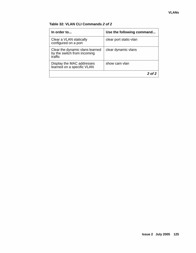
VLANs
Issue 2 July 2005 125
Clear a VLAN statically configured on a port
clear port static-vlan
Clear the dynamic vlans learned by the switch from incoming traffic
clear dynamic vlans
Display the MAC addresses learned on a specific VLAN
show cam vlan
Table 32: VLAN CLI Commands 2 of 2
In order to... Use the following command...
2 of 2
Avaya C360 Layer 2 Features
126 Installation and Configuration Guide Avaya C360 Multilayer Stackable Switches, version 4.5
IEEE 802.1x (Port Based Network Access Control)Port Based Network Access Control (IEEE 802.1x) is a method for performing authentication to obtain access to IEEE 802 LANs. The protocol defines an interaction between 3 entities:
● Supplicant - an entity at one end of a point-to-point LAN segment that is being authenticated by an authenticator attached to the other end of that link.
● Authenticator - an entity at one end of a point-to-point LAN segment that facilitates authentication of the entity attached to the other end of that link; in this case, the C360.
● Authentication (RADIUS) Server - an entity that provides an authentication service to an authenticator. This service determines, from the credentials provided by the supplicant, whether the supplicant is authorized to access the services provided by the authenticator.
The process begins with the supplicant trying to access a certain restricted network resource, and upon successful authentication by the authentication server, the supplicant is granted access to the network resources.
How 802.1x Authentication Works802.1x provides a means of authenticating and authorizing users attached to a LAN port and of preventing access to that port in cases where the authentication process fails. The authentication procedure is port based, which means:
● access control is achieved by enforcing authentication on connected ports
● if an end-point station that connects to a port is not authorized, the port state is set to "unauthorized" which closes the port to any traffic.
● As a result of an authentication attempt, the C360 port can be either in a "blocked" or a "forwarding" state.
802.1x interacts with existing standards to perform its authentication operation. Specifically, it makes use of Extensible Authentication Protocol (EAP) messages encapsulated within Ethernet frames (EAPOL), and EAP over RADIUS for the communication between the Authenticator and the Authentication Server.
IEEE 802.1x (Port Based Network Access Control)
Issue 2 July 2005 127
IEEE 802.1x Implementation in the C360This section lists the conditions that govern the implementation of the 802.1x standard in the C360 line:
● You can configure 802.1x on the 10/100 Mbps Ethernet ports only.
● 802.1x can work only if a RADIUS server is configured on the C360 and the RADIUS server is carefully configured to support 802.1x.
● 802.1x and port/intermodule redundancy can co-exist on the same ports.
● 802.1x and LAGs can coexist on the same ports.
● 802.1x and Spanning Tree can be simultaneously active on a module.
Note:Note: If either 802.1x or STP/RSTP are in a blocking state, the final state of the port will
be blocked.
● When 802.1x is activated, the application immediately places all ports in a blocking state unless they were declared "Force Authenticate". They will be reverted to "Forwarding" state only when the port is authorized by the RADIUS server.
Note:Note: The actual state of ports configured as "Force Authenticate" is determined by the
STA.
Configuring the C360 for 802.1xThis section lists the basic tasks required to configure a C360 stack for 802.1x. To configure C360 for 802.1x, do the following:
● Configure a RADIUS server on a network reachable from the C360:
- Create user names and passwords for allowed users.
- Make sure the EAP option is enabled on this server.
● Configure the C360 for RADIUS:
- Configure RADIUS parameters.
- Enable the RADIUS feature.
- Configure the port used to access the RADIUS server as "force-authorized."
Tip:Tip: You can configure on the RADIUS server a PVID, static VLAN binding and port
level for each authenticated user. If the port that the user is connected to is authorized, those parameters will be assigned to the port.
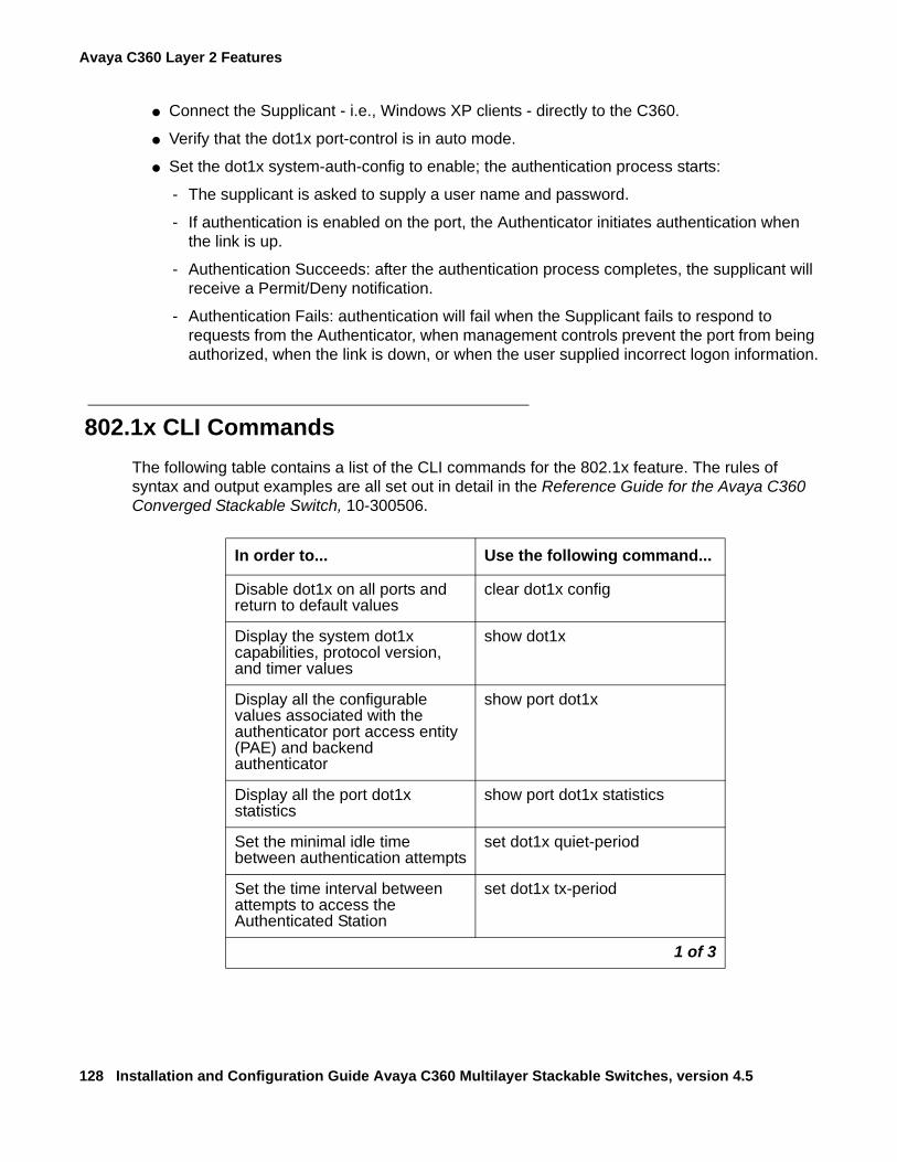
Avaya C360 Layer 2 Features
128 Installation and Configuration Guide Avaya C360 Multilayer Stackable Switches, version 4.5
● Connect the Supplicant - i.e., Windows XP clients - directly to the C360.
● Verify that the dot1x port-control is in auto mode.
● Set the dot1x system-auth-config to enable; the authentication process starts:
- The supplicant is asked to supply a user name and password.
- If authentication is enabled on the port, the Authenticator initiates authentication when the link is up.
- Authentication Succeeds: after the authentication process completes, the supplicant will receive a Permit/Deny notification.
- Authentication Fails: authentication will fail when the Supplicant fails to respond to requests from the Authenticator, when management controls prevent the port from being authorized, when the link is down, or when the user supplied incorrect logon information.
802.1x CLI CommandsThe following table contains a list of the CLI commands for the 802.1x feature. The rules of syntax and output examples are all set out in detail in the Reference Guide for the Avaya C360 Converged Stackable Switch, 10-300506.
In order to... Use the following command...
Disable dot1x on all ports and return to default values
clear dot1x config
Display the system dot1x capabilities, protocol version, and timer values
show dot1x
Display all the configurable values associated with the authenticator port access entity (PAE) and backend authenticator
show port dot1x
Display all the port dot1x statistics
show port dot1x statistics
Set the minimal idle time between authentication attempts
set dot1x quiet-period
Set the time interval between attempts to access the Authenticated Station
set dot1x tx-period
1 of 3
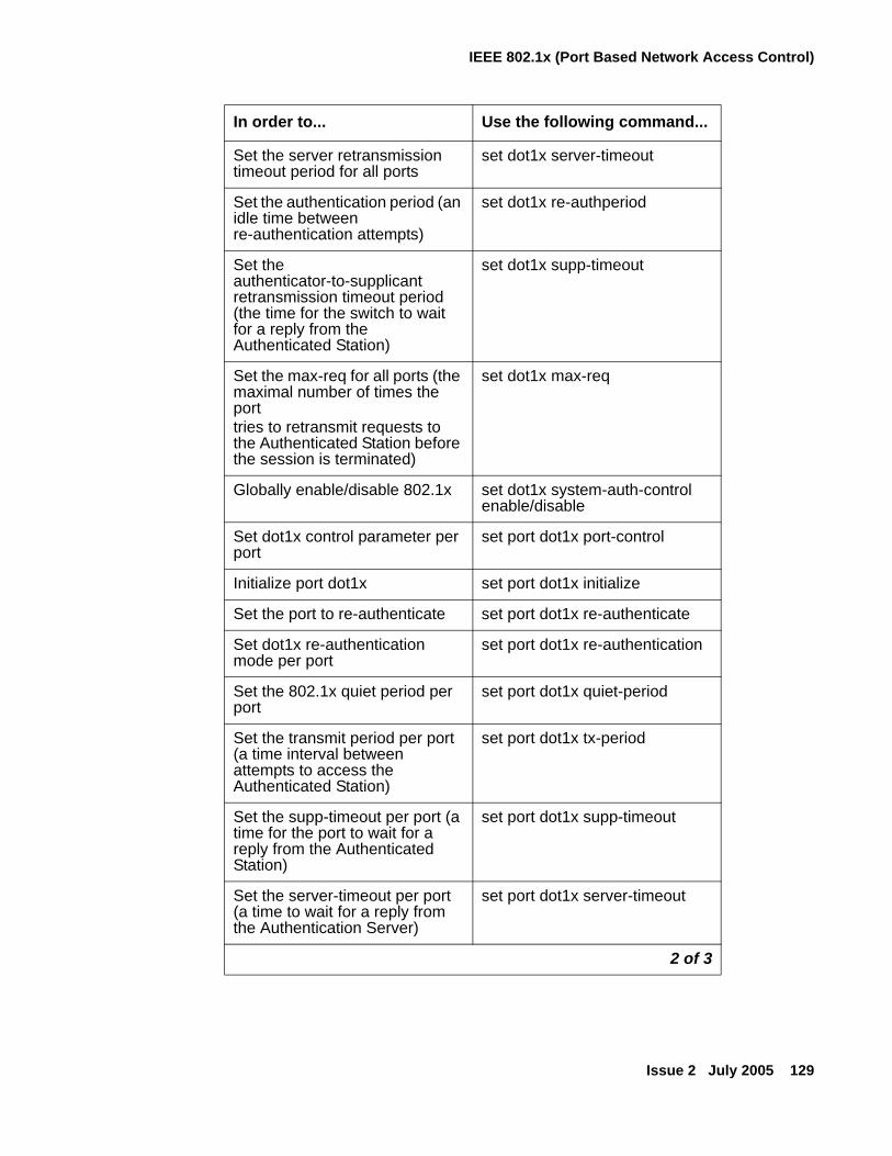
IEEE 802.1x (Port Based Network Access Control)
Issue 2 July 2005 129
Set the server retransmission timeout period for all ports
set dot1x server-timeout
Set the authentication period (an idle time between re-authentication attempts)
set dot1x re-authperiod
Set the authenticator-to-supplicant retransmission timeout period (the time for the switch to wait for a reply from the Authenticated Station)
set dot1x supp-timeout
Set the max-req for all ports (the maximal number of times the porttries to retransmit requests to the Authenticated Station before the session is terminated)
set dot1x max-req
Globally enable/disable 802.1x set dot1x system-auth-control enable/disable
Set dot1x control parameter per port
set port dot1x port-control
Initialize port dot1x set port dot1x initialize
Set the port to re-authenticate set port dot1x re-authenticate
Set dot1x re-authentication mode per port
set port dot1x re-authentication
Set the 802.1x quiet period per port
set port dot1x quiet-period
Set the transmit period per port (a time interval between attempts to access the Authenticated Station)
set port dot1x tx-period
Set the supp-timeout per port (a time for the port to wait for a reply from the Authenticated Station)
set port dot1x supp-timeout
Set the server-timeout per port (a time to wait for a reply from the Authentication Server)
set port dot1x server-timeout
In order to... Use the following command...
2 of 3
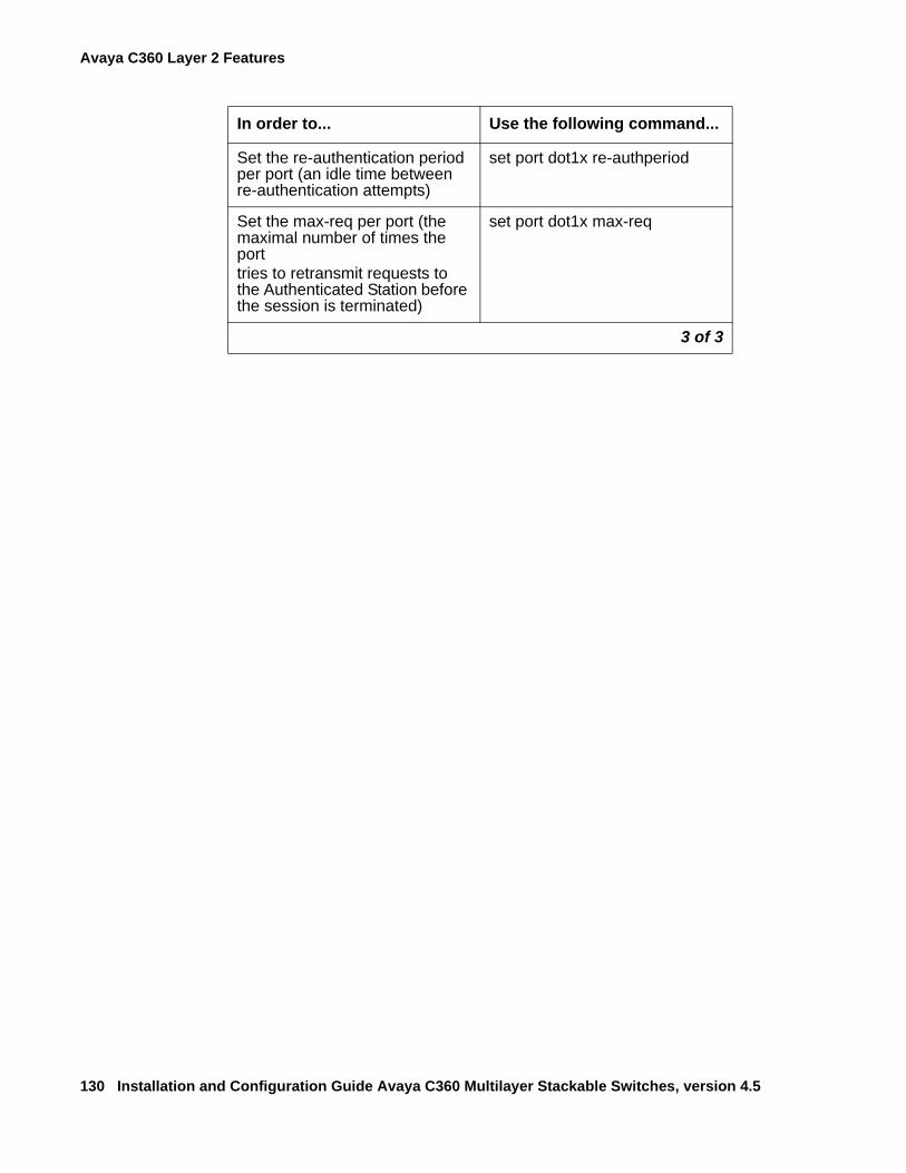
Avaya C360 Layer 2 Features
130 Installation and Configuration Guide Avaya C360 Multilayer Stackable Switches, version 4.5
Set the re-authentication period per port (an idle time between re-authentication attempts)
set port dot1x re-authperiod
Set the max-req per port (the maximal number of times the porttries to retransmit requests to the Authenticated Station before the session is terminated)
set port dot1x max-req
In order to... Use the following command...
3 of 3
Spanning Tree Protocol
Issue 2 July 2005 131
Spanning Tree Protocol
OverviewC360 switches support both common Spanning Tree protocol (802.1d) and the enhanced Rapid Spanning Tree protocol (802.1w). IEEE 802.1w is a faster and more sophisticated version of the 802.1d (STP) standard. Spanning Tree makes it possible to recover connectivity after an outage within a minute or so. RSTP, with its "rapid" algorithm, can restore connectivity to a network where a backbone link has failed in much less time.
In order to configure the switch to either common Spanning Tree or Rapid Spanning Tree protocol, use the set spantree version CLI command.
Spanning Tree ProtocolThe Spanning Tree Algorithm ensures the existence of a loop-free topology in networks that contain parallel bridges. A loop occurs when there are alternate routes between hosts. If there is a loop in an extended network, bridges may forward traffic indefinitely, which can result in increased traffic and degradation in network performance.
The Spanning Tree Algorithm:
● Produces a logical tree topology out of any arrangement of bridges. The result is a single path between any two end stations on an extended network.
● Provides a high degree of fault tolerance. It allows the network to automatically reconfigure the spanning tree topology if there is a bridge or data-path failure.
The Spanning Tree Algorithm requires five values to derive the spanning tree topology. These are:
1. A multicast address specifying all bridges on the extended network. This address is media-dependent and is automatically determined by the software.
2. A network-unique identifier for each bridge on the extended network.
3. A unique identifier for each bridge/LAN interface (a port).
4. The relative priority of each port.
5. The cost of each port.
After these values are assigned, bridges multicast and process the formatted frames (called Bridge Protocol Data Units, or BPDUs) to derive a single, loop-free topology throughout the extended network. The bridges exchange BPDU frames quickly, minimizing the time that service is unavailable between hosts.
Avaya C360 Layer 2 Features
132 Installation and Configuration Guide Avaya C360 Multilayer Stackable Switches, version 4.5
Spanning Tree per PortThe Spanning Tree can take up to 30 seconds to open traffic on a port. This delay can cause problems on ports carrying time-sensitive traffic. You can therefore enable/disable Spanning Tree in C360 on a per-port basis to minimize this effect.
Rapid Spanning Tree Protocol (RSTP)
About the 802.1w Standard
The enhanced feature set of the 802.1w standard includes:
● Bridge Protocol Data Unit (BPDU) type 2
● New port roles: Alternate port, Backup port
● Direct handshaking between adjacent bridges regarding a desired topology change (TC). This eliminates the need to wait for the timer to expire.
● Improvement in the time it takes to propagate TC information. Specifically, TC information does not have to be propagated all the way back to the Root Bridge (and back) to be changed.
● Origination of BPDUs on a port-by-port basis.
Port Roles
At the center of RSTP-specifically as an improvement over STP (802.1d)-are the roles that are assigned to the ports. There are four port roles:
● Root port - port closest to the root bridge
● Designated port - corresponding port on the remote bridge of the local root port
● Alternate port - an alternate route to the root
● Backup port - an alternate route to the network segment
The RSTP algorithm makes it possible to change port roles rapidly through its fast topology change propagation mechanism. For example, a port in the "blocking" state can be assigned the role of "alternate port." When the backbone of the network fails the port may be rapidly changed to forwarding.
Whereas the STA passively waited for the network to converge before turning a port into the forwarding state, RSTP actively confirms that a port can safely transition to forwarding without relying on any specific, programmed timer configuration.
Spanning Tree Protocol
Issue 2 July 2005 133
RSTP provides a means of fast network convergence after a topology change. It does this by assigning different treatments to different port types. The port types and the treatment they receive follow:
● Edge ports - Setting a port to "edge-port" admin state indicates that this port is connected directly to end stations that cannot create bridging loops in the network. These ports transition quickly to forwarding state. However, if BPDUs are received on an Edge port, it's operational state will be changed to "non-edge-port" and bridging loops will be avoided by the RSTP algorithm. The default admin state of all ports is "edge-port".
Note:Note: You must manually configure uplink and backbone ports (including LAG logical
ports) to be "non-edge" ports, using the CLI command set port edge admin state.
● Point-to-point Link ports - This port type applies only to ports interconnecting RSTP compliant switches and is used to define whether the devices are interconnected using shared Ethernet segment or point-to-point Ethernet link. RSTP convergence is faster when switches are connected using point-to-point links. The default setting for all ports - automatic detection of point-to-point link - is sufficient for most networks.
Spanning Tree Implementation in the C360RSTP is implemented in C360 family of products so that it is interoperable with the existing implementation of STP. In order to configure the switch to either common Spanning Tree or Rapid Spanning Tree protocol, use the set spantree version command.
The balance of this section lists the conditions and limitations that govern the implementation of Spanning Tree in the C360 family.
● RSTP's fast convergence benefits are lost when interacting with legacy (STP) bridges.
● When RSTP detects STP Bridge Protocol Data Units (BPDUs type 1) on a specific port, it will begin to "speak" 802.1d on this port only. Specifically, this means:
- 802.1d bridges will ignore RSTP BPDUs and drop them.
- 802.1d bridges will send 802.1d format BPDUs back to the switch.
- The switch will change to 802.1d mode for that port only.
The C360 configured to RSTP is therefore able to simultaneously work with other switches implementing either RSTP or STP without specific user intervention.
● Spanning Tree configuration is performed on the stack level.
● RSTP is interoperable with C360 Port Redundancy and 802.1x applications. If either RSTP or 802.1x put the port in blocking, its final state will be "blocking".
● You must manually configure uplink and backbone ports to be "non-edge" ports for both STP and RST using the set port edge admin state CLI command.
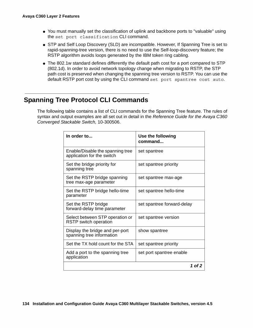
Avaya C360 Layer 2 Features
134 Installation and Configuration Guide Avaya C360 Multilayer Stackable Switches, version 4.5
● You must manually set the classification of uplink and backbone ports to "valuable" using the set port classification CLI command.
● STP and Self Loop Discovery (SLD) are incompatible. However, If Spanning Tree is set to rapid-spanning-tree version, there is no need to use the Self-loop-discovery feature; the RSTP algorithm avoids loops generated by the IBM token ring cabling.
● The 802.1w standard defines differently the default path cost for a port compared to STP (802.1d). In order to avoid network topology change when migrating to RSTP, the STP path cost is preserved when changing the spanning tree version to RSTP. You can use the default RSTP port cost by using the CLI command set port spantree cost auto.
Spanning Tree Protocol CLI CommandsThe following table contains a list of CLI commands for the Spanning Tree feature. The rules of syntax and output examples are all set out in detail in the Reference Guide for the Avaya C360 Converged Stackable Switch, 10-300506.
In order to... Use the following command...
Enable/Disable the spanning tree application for the switch
set spantree
Set the bridge priority for spanning tree
set spantree priority
Set the RSTP bridge spanning tree max-age parameter
set spantree max-age
Set the RSTP bridge hello-time parameter
set spantree hello-time
Set the RSTP bridge forward-delay time parameter
set spantree forward-delay
Select between STP operation or RSTP switch operation
set spantree version
Display the bridge and per-port spanning tree information
show spantree
Set the TX hold count for the STA set spantree priority
Add a port to the spanning tree application
set port spantree enable
1 of 2
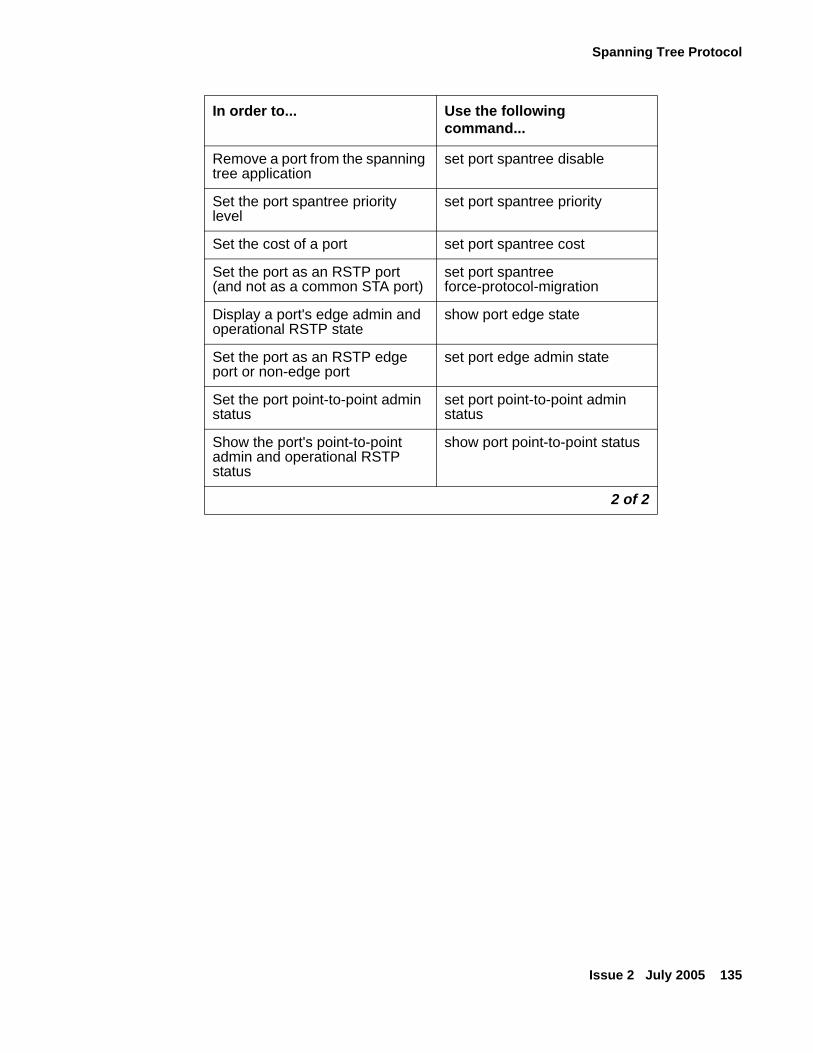
Spanning Tree Protocol
Issue 2 July 2005 135
Remove a port from the spanning tree application
set port spantree disable
Set the port spantree priority level
set port spantree priority
Set the cost of a port set port spantree cost
Set the port as an RSTP port (and not as a common STA port)
set port spantree force-protocol-migration
Display a port's edge admin and operational RSTP state
show port edge state
Set the port as an RSTP edge port or non-edge port
set port edge admin state
Set the port point-to-point admin status
set port point-to-point admin status
Show the port's point-to-point admin and operational RSTP status
show port point-to-point status
In order to... Use the following command...
2 of 2
Avaya C360 Layer 2 Features
136 Installation and Configuration Guide Avaya C360 Multilayer Stackable Switches, version 4.5
MAC Security The MAC security function is intended to filter incoming frames (from the line) with an unauthorized source MAC address (SA).
MAC Security Implementation in the C360When a frame is received on a secured port, its source MAC address is checked against the secured MAC Address Table. If either the source MAC address is not found there, or it is found but with a different ingress port location, then the frame is rejected
The C360 can be configured to take one of the following actions when an attempted intrusion occurs:
● Drop – Drops the packets for five seconds.
● Drop and notify – Drops the packets for five seconds and sends a notification to the management station.
● Disable and notify – Permanently disables the packets and sends a notification to the management station.
When the C360 is configured to send traps to report attempted intrusion, to prevent the flooding of the Console's trap log / network, the Agent sends an intruder alert every five seconds for the first 3 times a specific intruder is detected on a port, and then every 15 minutes if the intrusion continues.
You should first enable the MAC security global mode (use the set security mode CLI command) and then configure the ports which should be secured (use the set port security CLI command). When setting a port to secured, the MAC addresses that a currently learnt on this port are preserved and considered as secure MAC, unless they are removed using clear secure mac command. Individual secure MACs can also be added.
Tip:Tip: You can add a MAC address to more than one port on the device. This allows a
specific device to communicate with the switch via more than one ingress port. However the number of secured MAC addresses on any module cannot exceed 1,024.
Note:Note: Ports that are members of a port redundancy scheme should not be also
configured as secure ports.
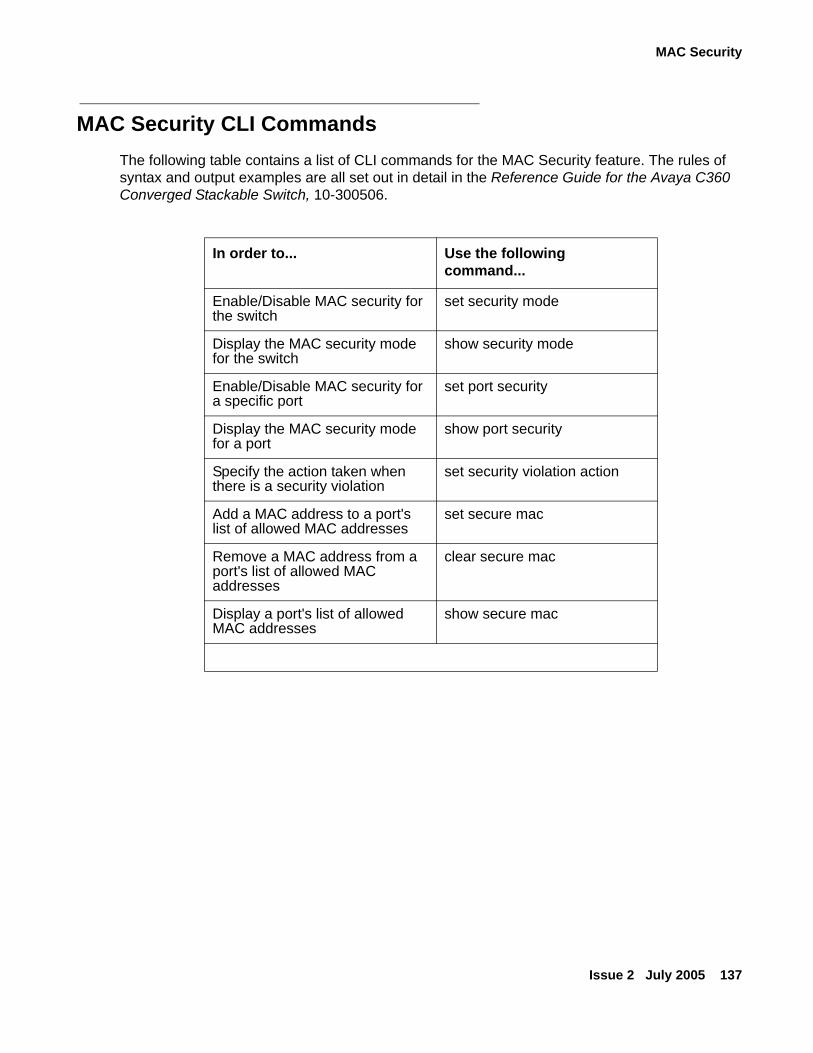
MAC Security
Issue 2 July 2005 137
MAC Security CLI CommandsThe following table contains a list of CLI commands for the MAC Security feature. The rules of syntax and output examples are all set out in detail in the Reference Guide for the Avaya C360 Converged Stackable Switch, 10-300506.
In order to... Use the following command...
Enable/Disable MAC security for the switch
set security mode
Display the MAC security mode for the switch
show security mode
Enable/Disable MAC security for a specific port
set port security
Display the MAC security mode for a port
show port security
Specify the action taken when there is a security violation
set security violation action
Add a MAC address to a port's list of allowed MAC addresses
set secure mac
Remove a MAC address from a port's list of allowed MAC addresses
clear secure mac
Display a port's list of allowed MAC addresses
show secure mac
Avaya C360 Layer 2 Features
138 Installation and Configuration Guide Avaya C360 Multilayer Stackable Switches, version 4.5
LAG (Link Aggregate Group)
LAG OverviewA LAG uses multiple ports to create a high bandwidth connection with another device. For example: Assigning four 100BASE-T ports to a LAG on an C360 allows the switch to communicate at an effective rate of 400 Mbps with another switch. LAGs provide a cost-effective method for creating a high bandwidth connection. LAGs also provide built-in redundancy for the ports that belong to a LAG. If a port in a LAG fails, its traffic is directed to another port within the LAG.
The behavior of the LAG is derived from the base port (the first port that becomes a LAG member). The attributes of the base port, such as port speed, VLAN number, etc., are applied to all the other member ports in the LAG.
When created, each LAG is automatically assigned a logical port number (usually designated 10x). This logical port number can then be used as any regular panel port for all configuration required for the LAG (Spanning Tree, Redundancy, etc.).
Note:Note: You need to erase all ports in the LAG in order to remove it.
LAG CLI CommandsThe following table contains a list of the CLI commands for the LAG feature. The rules of syntax and output examples are all set out in detail in the Reference Guide for the Avaya C360 Converged Stackable Switch, 10-300506.
In order to... Use the following command...
Enable or disable a Link Aggregation Group (LAG) logical port on the switch
set port channel
Display Link Aggregation Group (LAG) information for a specific switch or port
show port channel
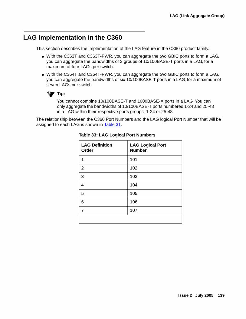
LAG (Link Aggregate Group)
Issue 2 July 2005 139
LAG Implementation in the C360This section describes the implementation of the LAG feature in the C360 product family.
● With the C363T and C363T-PWR, you can aggregate the two GBIC ports to form a LAG, you can aggregate the bandwidths of 3 groups of 10/100BASE-T ports in a LAG, for a maximum of four LAGs per switch.
● With the C364T and C364T-PWR, you can aggregate the two GBIC ports to form a LAG, you can aggregate the bandwidths of six 10/100BASE-T ports in a LAG, for a maximum of seven LAGs per switch.
Tip:Tip: You cannot combine 10/100BASE-T and 1000BASE-X ports in a LAG. You can
only aggregate the bandwidths of 10/100BASE-T ports numbered 1-24 and 25-48 in a LAG within their respective ports groups, 1-24 or 25-48.
The relationship between the C360 Port Numbers and the LAG logical Port Number that will be assigned to each LAG is shown in Table 31.
Table 33: LAG Logical Port Numbers
LAG Definition Order
LAG Logical Port Number
1 101
2 102
3 103
4 104
5 105
6 106
7 107
Avaya C360 Layer 2 Features
140 Installation and Configuration Guide Avaya C360 Multilayer Stackable Switches, version 4.5
Port RedundancyPort redundancy involves the duplication of devices, services, or connections, so that, in the event of a failure, the redundant device, service, or connection can take over for the one that failed.
In addition to Link Aggregation Groups - which comprise the basic redundancy mechanism within the switch - the C360 offers an additional port redundancy scheme. To achieve port redundancy, you can define a redundancy relationship between any two ports in a stack. One port is defined as the primary port and the other as the secondary port. If the primary port fails, the secondary port takes over. You can configure up to 20 pairs of ports (or LAGs) per stack for port redundancy, and one pair per stack for intermodule redundancy. Each pair contains a primary and secondary port. You can configure any type of port to be redundant to any other.
Port Redundancy OperationThe Port Redundancy feature supports up to 20 pairs of ports per stack. The redundant or secondary port takes over when the primary port link is down. Port redundancy provides for the following in the C360:
● Switchback from the secondary to primary port is allowed
● Switching time intervals can be set by the user
Tip:Tip: Port Redundancy interoperates with the Spanning Tree Algorithm.
The Port Redundancy feature functions as follows:
● Port Redundancy enables the user to establish 20 pairs of ports. Within each pair, primary and secondary ports are defined. To prevent loops, only one port is enabled at a time.
● Following initialization, the primary port is enabled and the secondary port is disabled.
- If the active port link fails, the system enables the secondary port.
- If the secondary port is enabled and the primary port link becomes available again, the system will "switchback" to the primary port, unless configured otherwise by the user.
● Two timers are available:
- "min-time-between-switchovers" - minimum time (in seconds) between the failure of the primary port link and switchover to the secondary (backup) port.
Tip:Tip: The first time the primary port fails, the switchover is immediate. This timer
applies to subsequent failures.
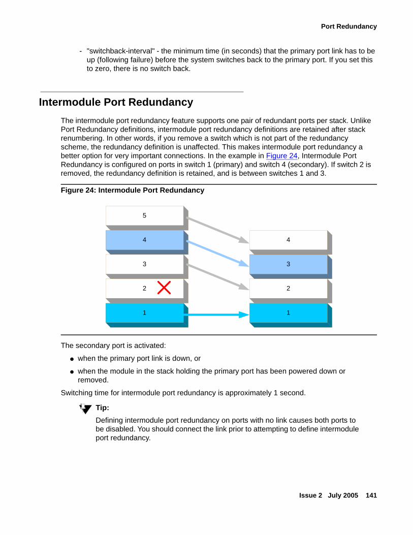
Port Redundancy
Issue 2 July 2005 141
- "switchback-interval" - the minimum time (in seconds) that the primary port link has to be up (following failure) before the system switches back to the primary port. If you set this to zero, there is no switch back.
Intermodule Port RedundancyThe intermodule port redundancy feature supports one pair of redundant ports per stack. Unlike Port Redundancy definitions, intermodule port redundancy definitions are retained after stack renumbering. In other words, if you remove a switch which is not part of the redundancy scheme, the redundancy definition is unaffected. This makes intermodule port redundancy a better option for very important connections. In the example in Figure 24, Intermodule Port Redundancy is configured on ports in switch 1 (primary) and switch 4 (secondary). If switch 2 is removed, the redundancy definition is retained, and is between switches 1 and 3.
Figure 24: Intermodule Port Redundancy
The secondary port is activated:
● when the primary port link is down, or
● when the module in the stack holding the primary port has been powered down or removed.
Switching time for intermodule port redundancy is approximately 1 second.
Tip:Tip: Defining intermodule port redundancy on ports with no link causes both ports to
be disabled. You should connect the link prior to attempting to define intermodule port redundancy.
5
4
3
2
1
4
3
2
1
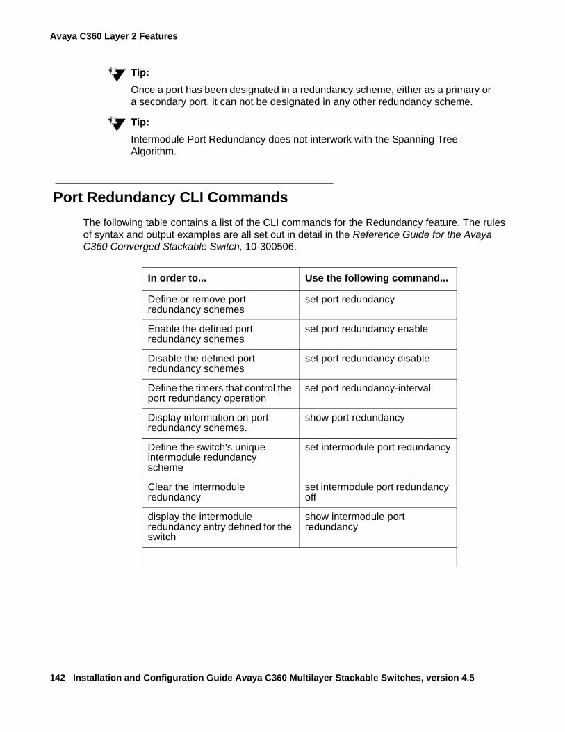
Avaya C360 Layer 2 Features
142 Installation and Configuration Guide Avaya C360 Multilayer Stackable Switches, version 4.5
Tip:Tip: Once a port has been designated in a redundancy scheme, either as a primary or
a secondary port, it can not be designated in any other redundancy scheme.
Tip:Tip: Intermodule Port Redundancy does not interwork with the Spanning Tree
Algorithm.
Port Redundancy CLI CommandsThe following table contains a list of the CLI commands for the Redundancy feature. The rules of syntax and output examples are all set out in detail in the Reference Guide for the Avaya C360 Converged Stackable Switch, 10-300506.
In order to... Use the following command...
Define or remove port redundancy schemes
set port redundancy
Enable the defined port redundancy schemes
set port redundancy enable
Disable the defined port redundancy schemes
set port redundancy disable
Define the timers that control the port redundancy operation
set port redundancy-interval
Display information on port redundancy schemes.
show port redundancy
Define the switch's unique intermodule redundancy scheme
set intermodule port redundancy
Clear the intermodule redundancy
set intermodule port redundancy off
display the intermodule redundancy entry defined for the switch
show intermodule port redundancy
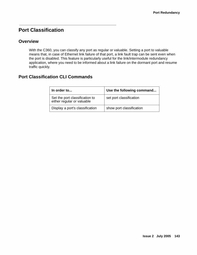
Port Redundancy
Issue 2 July 2005 143
Port Classification
Overview
With the C360, you can classify any port as regular or valuable. Setting a port to valuable means that, in case of Ethernet link failure of that port, a link fault trap can be sent even when the port is disabled. This feature is particularly useful for the link/intermodule redundancy application, where you need to be informed about a link failure on the dormant port and resume traffic quickly.
Port Classification CLI Commands
In order to... Use the following command...
Set the port classification to either regular or valuable
set port classification
Display a port's classification show port classification
Avaya C360 Layer 2 Features
144 Installation and Configuration Guide Avaya C360 Multilayer Stackable Switches, version 4.5
IP Multicast Filtering
OverviewIP Multicast is a method of sending a single copy of an IP packet to multiple destinations. It can be used by different applications including video streaming and video conferencing.
The Multicast packet is forwarded from the sender to the recipients, duplicated only when needed by routers along the way and sent in multiple directions such that it reaches all the members of the Multicast group. Multicast addresses are a special kind of IP addresses (class D), each identifying a multicast group. Stations join and leave multicast groups using IGMP. This is a control-plane protocol through which IP hosts register with their router to receive packets for certain multicast addresses.
IP multicast packets are transmitted on LANs in MAC multicast frames. Traditional LAN switches flood these multicast packets like broadcast packets to all stations in the VLAN. In order to avoid sending multicast packets where they are not required, multicast filtering functions may be added to the layer 2 switches, as described in IEEE standard 802.1D. Layer 2 switches capable of multicast filtering send the multicast packets only to ports connecting members of that multicast group. This is typically based on IGMP snooping.
The C360 supports multicast filtering. The C360 learns which switch ports need to receive which multicast packets and configures the necessary information into the switch's hardware tables. This learning is based on IGMP (version 1 or 2) snooping.
The multicast filtering function in the C360 is transparent to the IP hosts and routers. It does not affect the forwarding behavior apart from filtering multicast packets from certain ports where they are not needed. To the ports that do get the multicast, forwarding is performed in the same way as if there was no filtering, and the multicast packet will not be sent to any ports that would not receive it if there was no filtering.
The multicast filtering function operates per VLAN. A multicast packet arriving at the device on a certain VLAN will be forwarded only to a subset of the ports of that VLAN. If VLAN tagging mode is used on the output port, then the multicast packet will be tagged with the same VLAN number with which it arrived. This is interoperable with multicast routers that expect Layer 2 switching to be done independently for each VLAN.
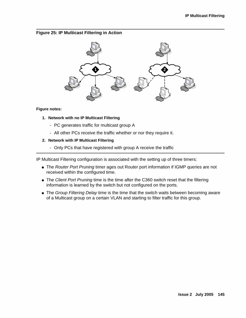
IP Multicast Filtering
Issue 2 July 2005 145
Figure 25: IP Multicast Filtering in Action
IP Multicast Filtering configuration is associated with the setting up of three timers:
● The Router Port Pruning timer ages out Router port information if IGMP queries are not received within the configured time.
● The Client Port Pruning time is the time after the C360 switch reset that the filtering information is learned by the switch but not configured on the ports.
● The Group Filtering Delay time is the time that the switch waits between becoming aware of a Multicast group on a certain VLAN and starting to filter traffic for this group.
Figure notes:
1. Network with no IP Multicast Filtering
- PC generates traffic for multicast group A
- All other PCs receive the traffic whether or nor they require it.
2. Network with IP Multicast Filtering
- Only PCs that have registered with group A receive the traffic
`
`
`
`
`
`
`
`
1 2
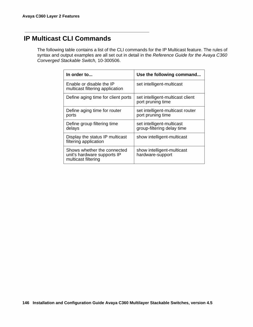
Avaya C360 Layer 2 Features
146 Installation and Configuration Guide Avaya C360 Multilayer Stackable Switches, version 4.5
IP Multicast CLI CommandsThe following table contains a list of the CLI commands for the IP Multicast feature. The rules of syntax and output examples are all set out in detail in the Reference Guide for the Avaya C360 Converged Stackable Switch, 10-300506.
In order to... Use the following command...
Enable or disable the IP multicast filtering application
set intelligent-multicast
Define aging time for client ports set intelligent-multicast client port pruning time
Define aging time for router ports
set intelligent-multicast router port pruning time
Define group filtering time delays
set intelligent-multicast group-filtering delay time
Display the status IP multicast filtering application
show intelligent-multicast
Shows whether the connected unit's hardware supports IP multicast filtering
show intelligent-multicast hardware-support
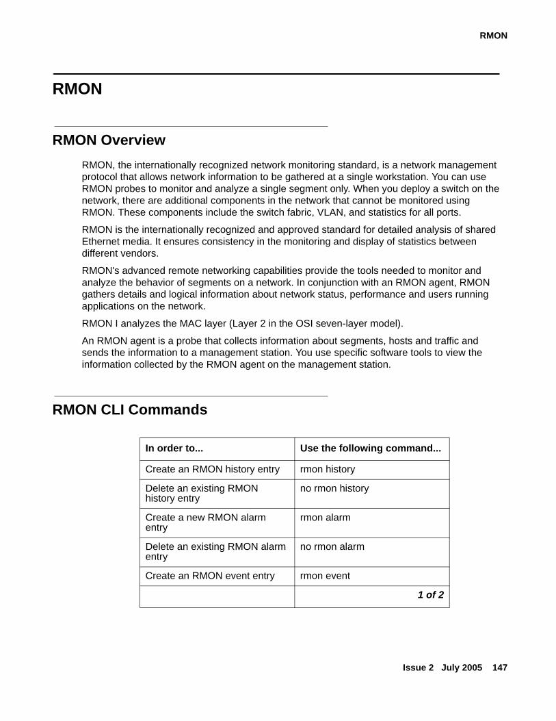
RMON
Issue 2 July 2005 147
RMON
RMON OverviewRMON, the internationally recognized network monitoring standard, is a network management protocol that allows network information to be gathered at a single workstation. You can use RMON probes to monitor and analyze a single segment only. When you deploy a switch on the network, there are additional components in the network that cannot be monitored using RMON. These components include the switch fabric, VLAN, and statistics for all ports.
RMON is the internationally recognized and approved standard for detailed analysis of shared Ethernet media. It ensures consistency in the monitoring and display of statistics between different vendors.
RMON's advanced remote networking capabilities provide the tools needed to monitor and analyze the behavior of segments on a network. In conjunction with an RMON agent, RMON gathers details and logical information about network status, performance and users running applications on the network.
RMON I analyzes the MAC layer (Layer 2 in the OSI seven-layer model).
An RMON agent is a probe that collects information about segments, hosts and traffic and sends the information to a management station. You use specific software tools to view the information collected by the RMON agent on the management station.
RMON CLI Commands
In order to... Use the following command...
Create an RMON history entry rmon history
Delete an existing RMON history entry
no rmon history
Create a new RMON alarm entry
rmon alarm
Delete an existing RMON alarm entry
no rmon alarm
Create an RMON event entry rmon event
1 of 2
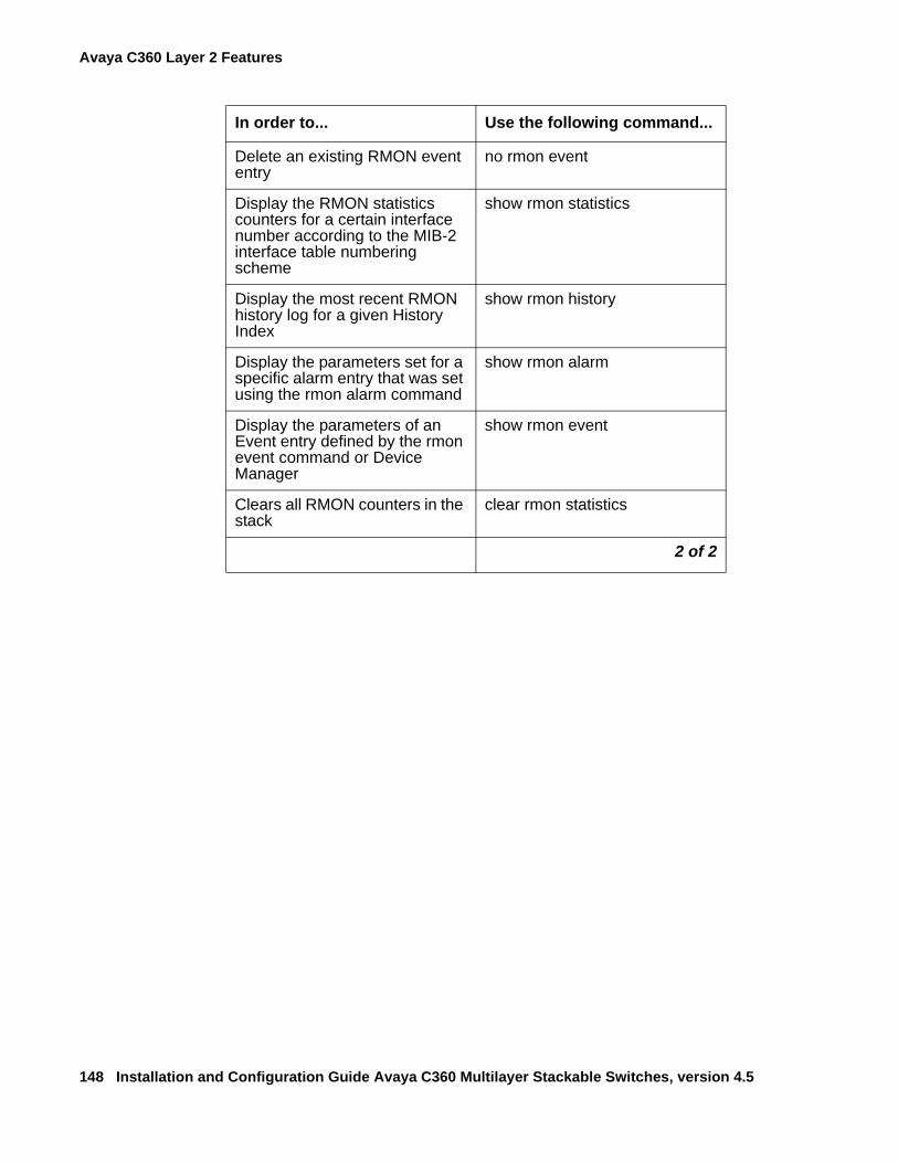
Avaya C360 Layer 2 Features
148 Installation and Configuration Guide Avaya C360 Multilayer Stackable Switches, version 4.5
Delete an existing RMON event entry
no rmon event
Display the RMON statistics counters for a certain interface number according to the MIB-2 interface table numbering scheme
show rmon statistics
Display the most recent RMON history log for a given History Index
show rmon history
Display the parameters set for a specific alarm entry that was set using the rmon alarm command
show rmon alarm
Display the parameters of an Event entry defined by the rmon event command or Device Manager
show rmon event
Clears all RMON counters in the stack
clear rmon statistics
In order to... Use the following command...
2 of 2
SMON
Issue 2 July 2005 149
SMON
SMON OverviewSMON is Avaya's standard-setting switch monitoring technology that has now been adopted as IETF standard RFC 2613. SMON extends the RMON standard to provide the switch monitoring tools and features you need to analyze the switched network and all its components.
SMON provides the basis for top-down network monitoring. Top-down monitoring starts when the you notice particular traffic flow patterns in a global view of the network. The network manager can progressively focus in and find the specific source or sources of the traffic.
Using this method, the amount of information the network manager must assess is kept to a minimum. Top-down monitoring is robust enough to enable control of even the most complex and sophisticated networks.
SMON is an extension of the RMON standard. SMON adds to the monitoring capabilities of RMON in the following ways:
● It provides additional tools and features for monitoring in the switch environment.
● It provides a global view of traffic flow on a network with multiple switches.
SMON monitoring provides:
● A global view of traffic for all switches on the network
● An overall view of traffic passing through a specific switch
● Detailed data of the hosts transmitting packets through a switch
● An analysis of traffic passing through each port connected to a switch, and
● A view of traffic between various hosts connected to a switch.
SMON extends both RMON I for the MAC layer, and RMON 2 for the network layer and higher. SMON monitoring collects and displays data in real-time.
Top-down view of all traffic:
● Network view for selected switches
● Network view for selected ports
● VLAN view
● History
Tip:Tip: In order to use SMON, you need to install the SMON license on the C360 switch
and use Avaya IM with SMON
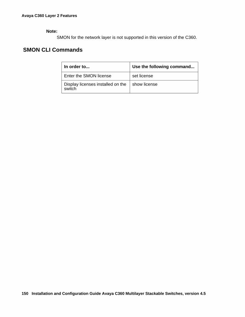
Avaya C360 Layer 2 Features
150 Installation and Configuration Guide Avaya C360 Multilayer Stackable Switches, version 4.5
Note:Note: SMON for the network layer is not supported in this version of the C360.
SMON CLI Commands
In order to... Use the following command...
Enter the SMON license set license
Display licenses installed on the switch
show license
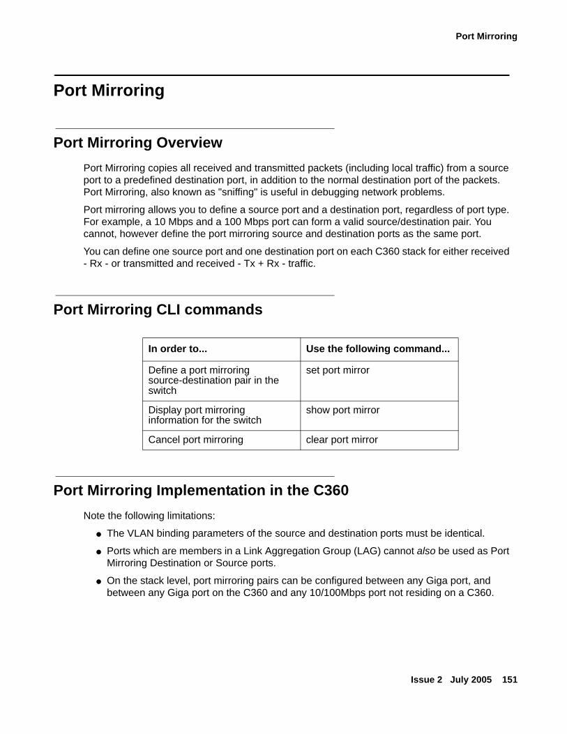
Port Mirroring
Issue 2 July 2005 151
Port Mirroring
Port Mirroring Overview Port Mirroring copies all received and transmitted packets (including local traffic) from a source port to a predefined destination port, in addition to the normal destination port of the packets. Port Mirroring, also known as "sniffing" is useful in debugging network problems.
Port mirroring allows you to define a source port and a destination port, regardless of port type. For example, a 10 Mbps and a 100 Mbps port can form a valid source/destination pair. You cannot, however define the port mirroring source and destination ports as the same port.
You can define one source port and one destination port on each C360 stack for either received - Rx - or transmitted and received - Tx + Rx - traffic.
Port Mirroring CLI commands
Port Mirroring Implementation in the C360 Note the following limitations:
● The VLAN binding parameters of the source and destination ports must be identical.
● Ports which are members in a Link Aggregation Group (LAG) cannot also be used as Port Mirroring Destination or Source ports.
● On the stack level, port mirroring pairs can be configured between any Giga port, and between any Giga port on the C360 and any 10/100Mbps port not residing on a C360.
In order to... Use the following command...
Define a port mirroring source-destination pair in the switch
set port mirror
Display port mirroring information for the switch
show port mirror
Cancel port mirroring clear port mirror
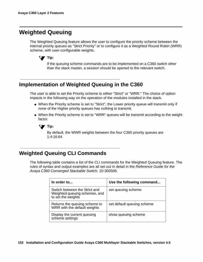
Avaya C360 Layer 2 Features
152 Installation and Configuration Guide Avaya C360 Multilayer Stackable Switches, version 4.5
Weighted QueuingThe Weighted Queuing feature allows the user to configure the priority scheme between the internal priority queues as "Strict Priority" or to configure it as a Weighted Round Robin (WRR) scheme, with user-configurable weights.
Tip:Tip: If the queuing scheme commands are to be implemented on a C360 switch other
than the stack master, a session should be opened to the relevant switch.
Implementation of Weighted Queuing in the C360The user is able to set the Priority scheme to either "Strict" or "WRR." The choice of option impacts in the following way on the operation of the modules installed in the stack.
● When the Priority scheme is set to "Strict", the Lower priority queue will transmit only if none of the Higher priority queues has nothing to transmit.
● When the Priority scheme is set to "WRR" queues will be transmit according to the weight factor.
Tip:Tip: By default, the WWR weights between the four C360 priority queues are
1:4:16:64
Weighted Queuing CLI CommandsThe following table contains a list of the CLI commands for the Weighted Queuing feature. The rules of syntax and output examples are all set out in detail in the Reference Guide for the Avaya C360 Converged Stackable Switch, 10-300506.
In order to... Use the following command...
Switch between the Strict and Weighted queuing schemes, and to set the weights
set queuing scheme
Returns the queuing scheme to WRR with the default weights
set default queuing scheme
Display the current queuing scheme settings
show queuing scheme
LLDP Agent
Issue 2 July 2005 153
LLDP Agent
LLDP Agent OverviewIEEE 802.1AB Link Layer Discovery Protocol (LLDP) simplifies troubleshooting of enterprise networks and enhances the ability of network management tools to discover and maintain accurate network topologies in multi-vendor environments. It defines a set of advertisement messages, called TLVs, a protocol for transmitting and receiving the advertisements, and a method for storing the information contained in the received advertisements.
The LLDP protocol allows stations attached to a LAN to advertise information about the system (such as its major capabilities and its management address) and information regarding the station's point of attachment to the LAN (port ID and VLAN information) to other stations attached to the same LAN. These can all be reported to management stations via IEEE-defined Simple Network Management Protocol (SNMP) Management Information Bases (MIBs).
LLDP information is transmitted periodically. The IEEE has defined a recommended transmission rate of 30 seconds, however, the transmission rate is adjustable. LLDP devices, after receiving an LLDP message from a neighboring network device, stores the LLDP information in an SNMP MIB. This information is valid only for a finite period of time after TLV reception. The time is defined by the LLDP Time to Live (TTL) TLV value that is contained within the received packet, unless refreshed by a newly received TLV. The IEEE recommends a TTL value of 120 seconds, but you can change it if necessary. This ensures that only valid LLDP information is stored in the network devices and is available to network management systems. LLDP information is associated with the specific device that sends it. The device itself is uniquely identified by the receiving party via both received chassis ID and port ID values. Multiple LLDP devices can reside on a single port, using a hub for example, and all of the devices are reported via MIB. You can enable (Rx and TX, Rx or Tx) or disable LLDP operation on a per-port basis.
Supported TLVs
Mandatory● End-of-LLDPDU
● Chassis ID
● Port ID
● Time to Live
Optional● Port description
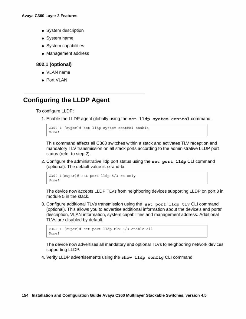
Avaya C360 Layer 2 Features
154 Installation and Configuration Guide Avaya C360 Multilayer Stackable Switches, version 4.5
● System description
● System name
● System capabilities
● Management address
802.1 (optional)● VLAN name
● Port VLAN
Configuring the LLDP AgentTo configure LLDP:
1. Enable the LLDP agent globally using the set lldp system-control command.
This command affects all C360 switches within a stack and activates TLV reception and mandatory TLV transmission on all stack ports according to the administrative LLDP port status (refer to step 2).
2. Configure the administrative lldp port status using the set port lldp CLI command (optional). The default value is rx-and-tx.
The device now accepts LLDP TLVs from neighboring devices supporting LLDP on port 3 in module 5 in the stack.
3. Configure additional TLVs transmission using the set port lldp tlv CLI command (optional). This allows you to advertise additional information about the device's and ports' description, VLAN information, system capabilities and management address. Additional TLVs are disabled by default.
The device now advertises all mandatory and optional TLVs to neighboring network devices supporting LLDP.
4. Verify LLDP advertisements using the show lldp config CLI command.
C360-1 (super)# set lldp system-control enableDone!
C360-1(super)# set port lldp 5/3 rx-onlyDone!
C360-1 (super)# set port lldp tlv 5/3 enable allDone!
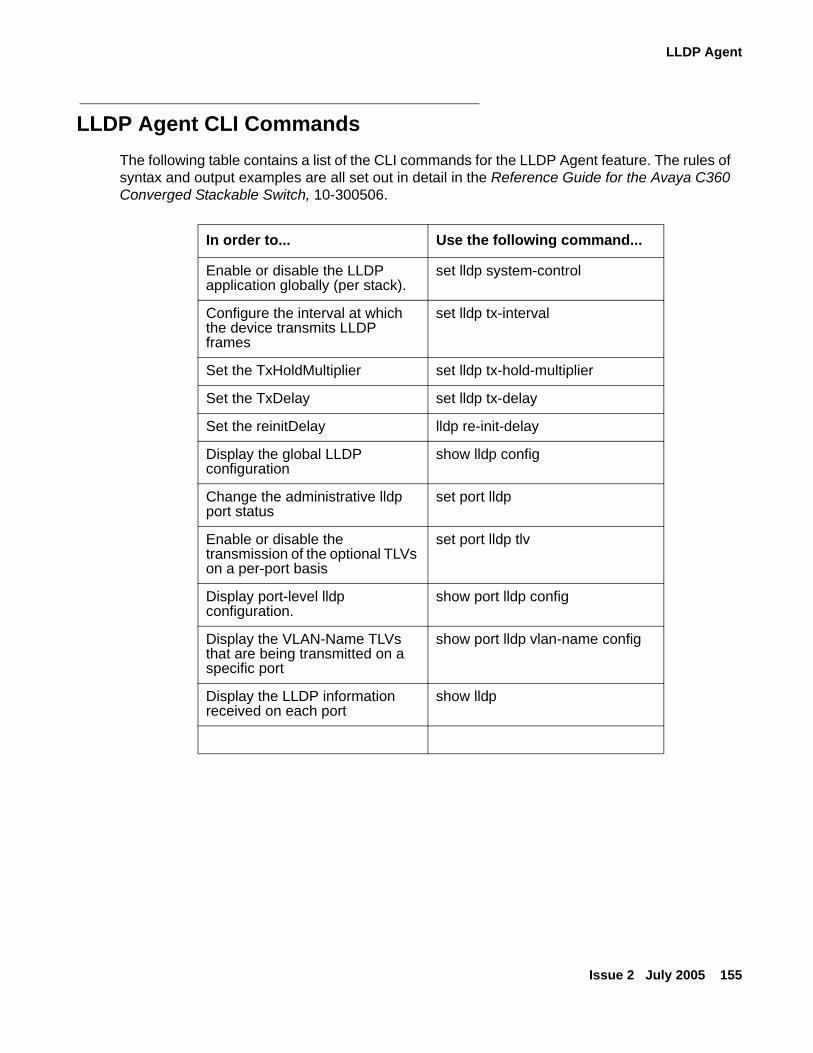
LLDP Agent
Issue 2 July 2005 155
LLDP Agent CLI CommandsThe following table contains a list of the CLI commands for the LLDP Agent feature. The rules of syntax and output examples are all set out in detail in the Reference Guide for the Avaya C360 Converged Stackable Switch, 10-300506.
In order to... Use the following command...
Enable or disable the LLDP application globally (per stack).
set lldp system-control
Configure the interval at which the device transmits LLDP frames
set lldp tx-interval
Set the TxHoldMultiplier set lldp tx-hold-multiplier
Set the TxDelay set lldp tx-delay
Set the reinitDelay lldp re-init-delay
Display the global LLDP configuration
show lldp config
Change the administrative lldp port status
set port lldp
Enable or disable the transmission of the optional TLVs on a per-port basis
set port lldp tlv
Display port-level lldp configuration.
show port lldp config
Display the VLAN-Name TLVs that are being transmitted on a specific port
show port lldp vlan-name config
Display the LLDP information received on each port
show lldp

Avaya C360 Layer 2 Features
156 Installation and Configuration Guide Avaya C360 Multilayer Stackable Switches, version 4.5
Issue 2 July 2005 157
Chapter 9: Avaya C360 Layer 3 Features
This section describes the C360 Layer 3 features. It provides the basic procedures for configuring the C360 for Layer 3 operation.
● Obtaining and Activating a License Key
● What is Routing?
● Routing Configuration
● IP Configuration
● RIP (Routing Interchange Protocol) Configuration
● OSPF (Open Shortest Path First) Configuration
● Static Routing Configuration
● Route Redistribution
● ARP (Address Resolution Protocol) Table Configuration
● BOOTP/DHCP (Dynamic Host Configuration Protocol) Relay Configuration
● NetBIOS Re-broadcast Configuration
● VRRP (Virtual Router Redundancy Protocol) Configuration
● Policy Configuration
● IP Fragmentation and Reassembly
Layer 3 features only apply to the C360 operating in router mode. You must purchase a Routing License Key Certificate for the C360 and activate the feature in order to operate in router mode. Refer to Obtaining and Activating a License Key on page 158 for further information.
Avaya C360 Layer 3 Features
158 Installation and Configuration Guide Avaya C360 Multilayer Stackable Switches, version 4.5
Obtaining and Activating a License KeyEach Certificate is specific for:
● The switch type.
● The required feature.
● The number of devices.
After you purchase a Routing Licence Key Certificate, you must obtain and activate a Routing License Key.
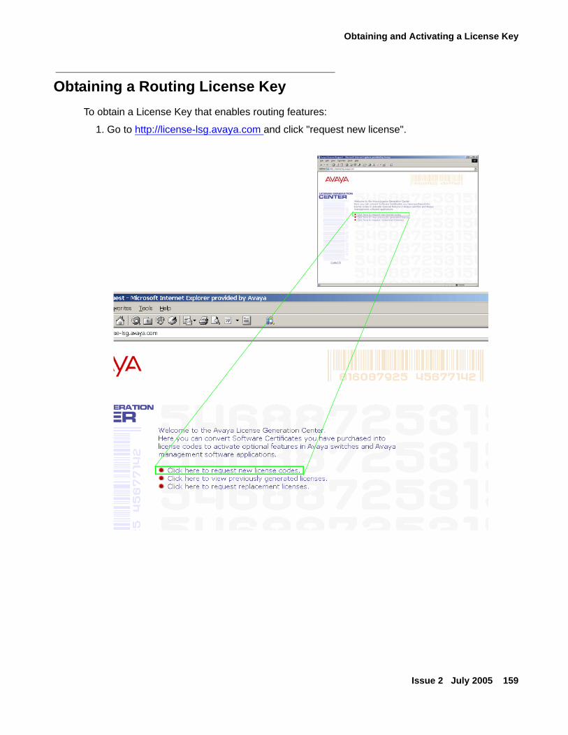
Obtaining and Activating a License Key
Issue 2 July 2005 159
Obtaining a Routing License KeyTo obtain a License Key that enables routing features:
1. Go to http://license-lsg.avaya.com and click "request new license".
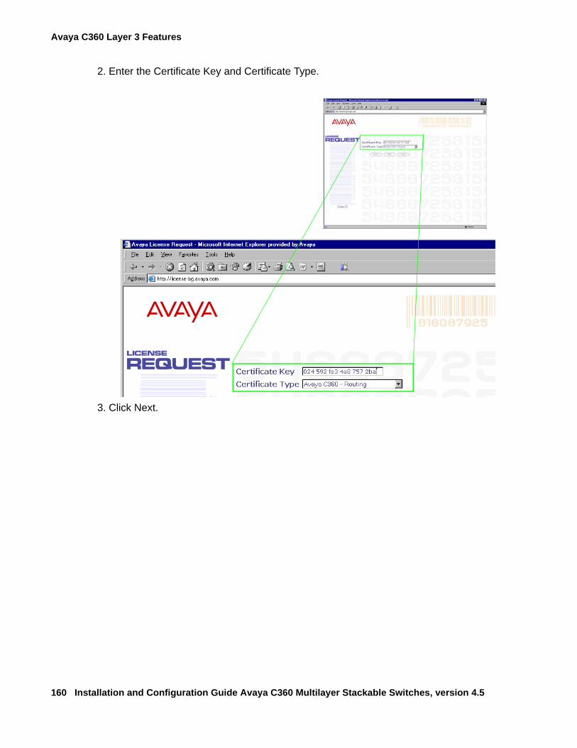
Avaya C360 Layer 3 Features
160 Installation and Configuration Guide Avaya C360 Multilayer Stackable Switches, version 4.5
2. Enter the Certificate Key and Certificate Type.
3. Click Next.
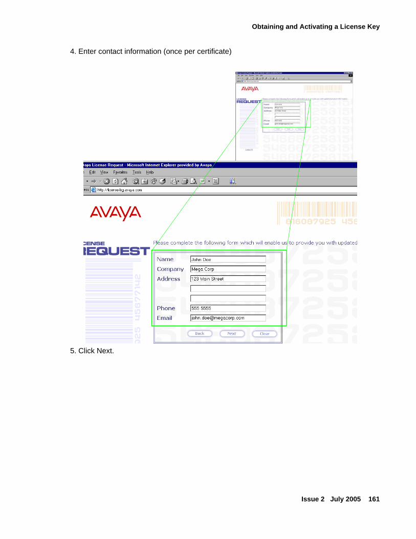
Obtaining and Activating a License Key
Issue 2 July 2005 161
4. Enter contact information (once per certificate)
5. Click Next.
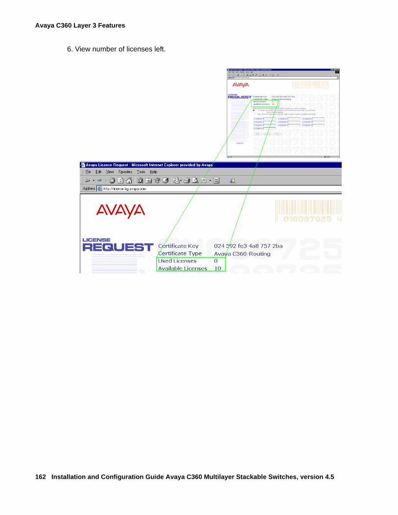
Avaya C360 Layer 3 Features
162 Installation and Configuration Guide Avaya C360 Multilayer Stackable Switches, version 4.5
6. View number of licenses left.
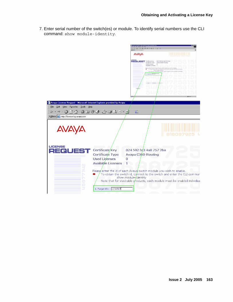
Obtaining and Activating a License Key
Issue 2 July 2005 163
7. Enter serial number of the switch(es) or module. To identify serial numbers use the CLI command: show module-identity.
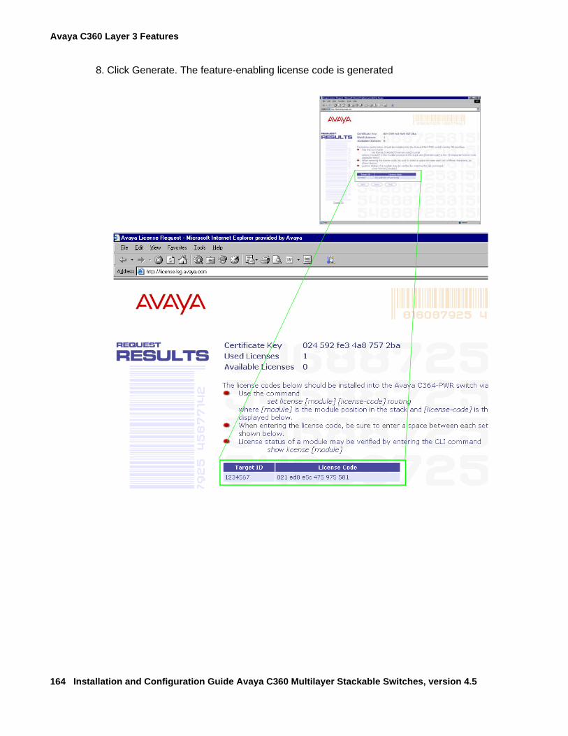
Avaya C360 Layer 3 Features
164 Installation and Configuration Guide Avaya C360 Multilayer Stackable Switches, version 4.5
8. Click Generate. The feature-enabling license code is generated
Obtaining and Activating a License Key
Issue 2 July 2005 165
Activating a Routing License KeyTo activate a Routing License Key:
1. Enter the acquired Routing License Key into the C360 switch using the set license CLI CLI command.set license [module] [license] [featureName]
where:
module - C360 switch number (the location of the device in the stack)
license - license code
featureName - routing
and press Enter.
2. Reset the module.
3. Check that the license is activated using the show license CLI command.
License Key CLI Commands
In order to... Use the following command...
Configure the feature license set license
Display the feature license show license
Display the switch identity required for acquiring a license
show module-identity
Avaya C360 Layer 3 Features
166 Installation and Configuration Guide Avaya C360 Multilayer Stackable Switches, version 4.5
What is Routing?Routing enables transfer of a data packet from source to destination using a device called a router. Routing involves two basic activities:
● determining optimal routing paths
● transmitting information packets through an internetwork
Routers use routing tables to determine the routes to particular network destinations and, in some cases, metrics associated with those routes. Routers communicate with one another and maintain their routing tables through the transmission of a variety of messages.
The Routing Update Message is one such message. Routing Updates generally consist of all or a portion of a routing table. By analyzing Routing Updates from all routers, a router can build a detailed picture of network topology.
A Link-State Advertisement is another example of a message sent between routers. Link-State Advertisements inform other routers of the state of the sender's links. Link information can also be used to build a complete picture of the network's topology. Once the network topology is understood, routers can determine optimal routes to network destinations.
Routers can route only those messages that are transmitted in a routable protocol, such as IP or IPX. Messages in non-routable protocols, such as NetBIOS and LAT, cannot be routed, but they can be transferred from LAN to LAN via a bridge.
When a router receives a packet, it examines the packet's destination protocol address. The router then determines whether it knows how to forward the packet to the next hop. If the router does not know how to forward the packet, it typically drops the packet unless a default gateway is defined. If the router knows how to forward the packet, it changes the packet destination's physical address to that of the next hop and transmits the packet.
The next hop may or may not be the ultimate destination host. If not, the next hop is usually another router, which executes the same switching decision process. As the packet moves through the internetwork, its physical address changes but its protocol address remains constant. This process is illustrated in the figure below.
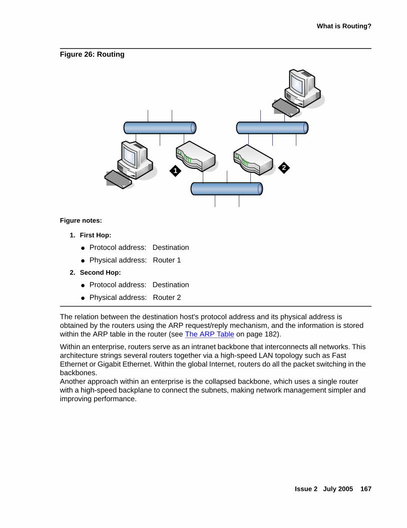
What is Routing?
Issue 2 July 2005 167
Figure 26: Routing
The relation between the destination host's protocol address and its physical address is obtained by the routers using the ARP request/reply mechanism, and the information is stored within the ARP table in the router (see The ARP Table on page 182).
Within an enterprise, routers serve as an intranet backbone that interconnects all networks. This architecture strings several routers together via a high-speed LAN topology such as Fast Ethernet or Gigabit Ethernet. Within the global Internet, routers do all the packet switching in the backbones.Another approach within an enterprise is the collapsed backbone, which uses a single router with a high-speed backplane to connect the subnets, making network management simpler and improving performance.
Figure notes:
1. First Hop:
● Protocol address: Destination
● Physical address: Router 1
2. Second Hop:
● Protocol address: Destination
● Physical address: Router 2
`
` 1 2
Avaya C360 Layer 3 Features
168 Installation and Configuration Guide Avaya C360 Multilayer Stackable Switches, version 4.5
Routing Configuration
ForwardingThe C360 forwards IP packets between IP networks. When it receives an IP packet through one of its interfaces, it forwards the packet through one of its interfaces. The C360 supports multinetting, enabling it to forward packets between IP subnets on the same VLAN as well as between different VLANs. Forwarding is performed through standard means in Router mode.
Multinetting (Multiple Subnets per VLAN)In Router Mode, most applications such as RIP and OSPF, operate per IP interface. Other applications such as VRRP and DHCP/BOOTP Relay operate per VLAN. Configuration of these applications is done in the Interface mode. When there is only a single interface (subnet) per VLAN then system behavior is intuitive since a subnet and a VLAN are the same.
Multiple interfaces (subnets) per VLAN are more complicated. For example, if there are two interfaces over the same VLAN and you configure DHCP server on one interface, it will be used also for the second interface over the same VLAN. This behavior might be less expected and in some cases wrong.
In order to prevent misconfiguration and unexpected results, the C360 prevents configuration of VLAN-oriented commands on an interface unless explicitly you specifically request it by the user via the "enable vlan commands" CLI command.
Configuring the "enable vlan commands" on one interface defeats this option on other interfaces that belong to the same VLAN. This ensures that VLAN-oriented commands can be configured from one interface only.
In case there is only one interface over a VLAN, then VLAN oriented commands for this VLAN can be configured through the single interface without using the "enable vlan commands" command.
Tip:Tip: VLAN-oriented commands that were configured affect the VLAN of the interface
that was used at the time the command was issued.
Tip:Tip: If you move the interface another VLAN using the ip vlan CLI command,
VLAN-oriented configuration still relates to the original VLAN.
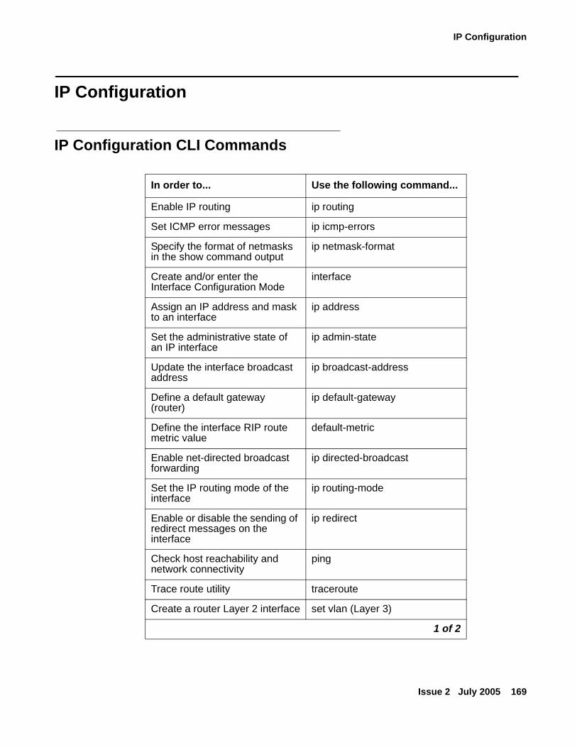
IP Configuration
Issue 2 July 2005 169
IP Configuration
IP Configuration CLI Commands
In order to... Use the following command...
Enable IP routing ip routing
Set ICMP error messages ip icmp-errors
Specify the format of netmasks in the show command output
ip netmask-format
Create and/or enter the Interface Configuration Mode
interface
Assign an IP address and mask to an interface
ip address
Set the administrative state of an IP interface
ip admin-state
Update the interface broadcast address
ip broadcast-address
Define a default gateway (router)
ip default-gateway
Define the interface RIP route metric value
default-metric
Enable net-directed broadcast forwarding
ip directed-broadcast
Set the IP routing mode of the interface
ip routing-mode
Enable or disable the sending of redirect messages on the interface
ip redirect
Check host reachability and network connectivity
ping
Trace route utility traceroute
Create a router Layer 2 interface set vlan (Layer 3)
1 of 2
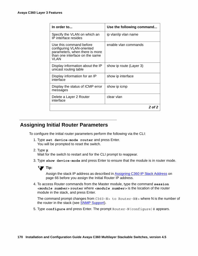
Avaya C360 Layer 3 Features
170 Installation and Configuration Guide Avaya C360 Multilayer Stackable Switches, version 4.5
Assigning Initial Router ParametersTo configure the initial router parameters perform the following via the CLI:
1. Type set device-mode router and press Enter.You will be prompted to reset the switch.
2. Type y. Wait for the switch to restart and for the CLI prompt to reappear.
3. Type show device-mode and press Enter to ensure that the module is in router mode.
Tip:Tip: Assign the stack IP address as described in Assigning C360 IP Stack Address on
page 66 before you assign the Initial Router IP address.
4. To access Router commands from the Master module, type the command session <module number> router where <module number> is the location of the router module in the stack, and press Enter.
The command prompt changes from C360-N> to Router-N#> where N is the number of the router in the stack (see SNMP Support).
5. Type configure and press Enter. The prompt Router-N(configure)# appears.
Specify the VLAN on which an IP interface resides
ip vlan/ip vlan name
Use this command before configuring VLAN-oriented parameters, when there is more than one interface on the same VLAN
enable vlan commands
Display information about the IP unicast routing table
show ip route (Layer 3)
Display information for an IP interface
show ip interface
Display the status of ICMP error messages
show ip icmp
Delete a Layer 2 Router interface
clear vlan
In order to... Use the following command...
2 of 2
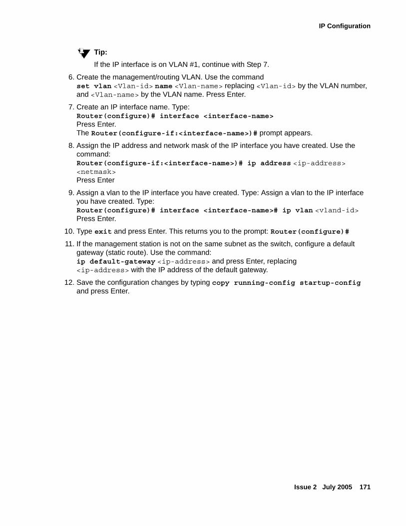
IP Configuration
Issue 2 July 2005 171
Tip:Tip: If the IP interface is on VLAN #1, continue with Step 7.
6. Create the management/routing VLAN. Use the command set vlan <Vlan-id> name <Vlan-name> replacing <Vlan-id> by the VLAN number, and <Vlan-name> by the VLAN name. Press Enter.
7. Create an IP interface name. Type:Router(configure)# interface <interface-name> Press Enter. The Router(configure-if:<interface-name>)# prompt appears.
8. Assign the IP address and network mask of the IP interface you have created. Use the command:Router(configure-if:<interface-name>)# ip address <ip-address> <netmask>Press Enter
9. Assign a vlan to the IP interface you have created. Type: Assign a vlan to the IP interface you have created. Type: Router(configure)# interface <interface-name># ip vlan <vland-id> Press Enter.
10. Type exit and press Enter. This returns you to the prompt: Router(configure)#
11. If the management station is not on the same subnet as the switch, configure a default gateway (static route). Use the command:ip default-gateway <ip-address> and press Enter, replacing <ip-address> with the IP address of the default gateway.
12. Save the configuration changes by typing copy running-config startup-config and press Enter.
Avaya C360 Layer 3 Features
172 Installation and Configuration Guide Avaya C360 Multilayer Stackable Switches, version 4.5
RIP (Routing Interchange Protocol) Configuration
RIP OverviewRIP is a "distance vector protocol"- that is, the router decides which path to use on distance (the number of intermediate hops). In order for this protocol to work correctly, all of the routers (and possibly the nodes) need to gather information on how to reach each destination in the Internet. The very simplicity of RIP has a disadvantage, however: it does not take into account the network bandwidth, physical cost, data priority, and so on.
The C360 supports the widely used RIP routing protocol (both RIPv1 and RIPv2). The RIPv1 protocol imposes some limitations on the network design with regard to subnetting. When operating RIPv1, you must not configure variable length subnet masks (VLMS). Each IP network must have a single mask, implying that all subnets in a given IP network are of the same size. Also, when operating RIPv1, you must not configure supernets, which are networks with a mask smaller than the natural net mask of the address class, such as 192.1.0.0 with mask 255.255.0.0 (smaller than the natural class C mask which is 255.255.255.0). For detailed descriptions of RIP refer to the standards and published literature.
RIPv2 is a new version of the RIP routing protocol but with some advantages over RIPv1. RIPv2 solves some of the problems associated with RIPv1. The most important change in RIPv2 is the addition of a subnet mask field which allows RIPv2 to support variable length subnets. RIPv2 also includes an authentication mechanism similar to the one used in OSPF.
The RIP version, 1 or 2, is configured per IP interface. Configuration must be homogenous on all routers on each subnet-there can not be both RIPv1 and RIPv2 routers configured on the same subnet. However, different IP interfaces of the C360 can be configured with different RIP versions (as long as all routers on the subnet are configured to the same version).
RIPv2 and RIPv1 are considered the same protocol with regard to redistribution to/from OSPF and static route preferences.
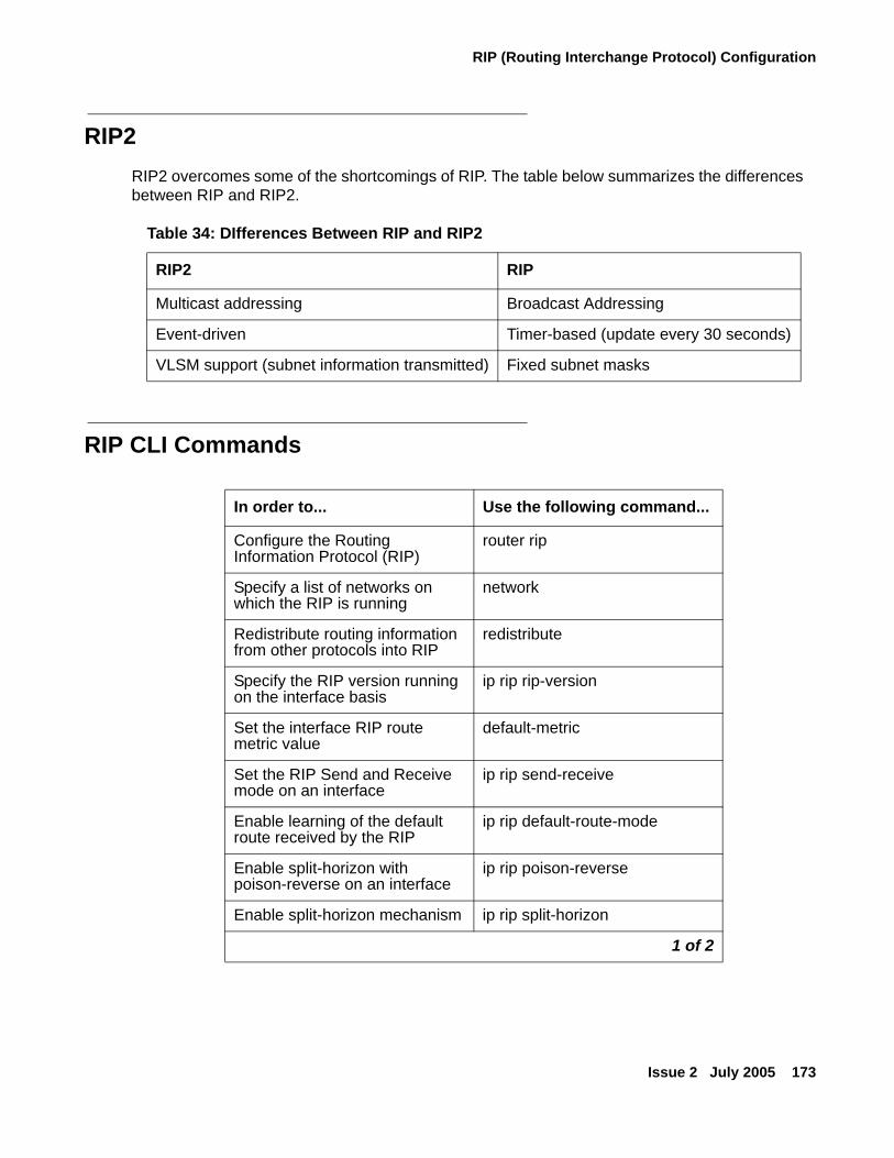
RIP (Routing Interchange Protocol) Configuration
Issue 2 July 2005 173
RIP2RIP2 overcomes some of the shortcomings of RIP. The table below summarizes the differences between RIP and RIP2.
RIP CLI Commands
Table 34: DIfferences Between RIP and RIP2
RIP2 RIP
Multicast addressing Broadcast Addressing
Event-driven Timer-based (update every 30 seconds)
VLSM support (subnet information transmitted) Fixed subnet masks
In order to... Use the following command...
Configure the Routing Information Protocol (RIP)
router rip
Specify a list of networks on which the RIP is running
network
Redistribute routing information from other protocols into RIP
redistribute
Specify the RIP version running on the interface basis
ip rip rip-version
Set the interface RIP route metric value
default-metric
Set the RIP Send and Receive mode on an interface
ip rip send-receive
Enable learning of the default route received by the RIP
ip rip default-route-mode
Enable split-horizon with poison-reverse on an interface
ip rip poison-reverse
Enable split-horizon mechanism ip rip split-horizon
1 of 2
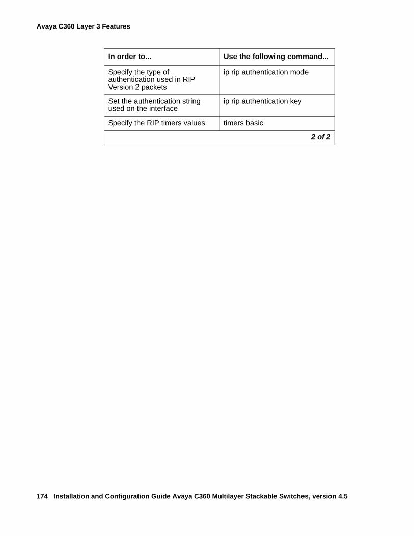
Avaya C360 Layer 3 Features
174 Installation and Configuration Guide Avaya C360 Multilayer Stackable Switches, version 4.5
Specify the type of authentication used in RIP Version 2 packets
ip rip authentication mode
Set the authentication string used on the interface
ip rip authentication key
Specify the RIP timers values timers basic
In order to... Use the following command...
2 of 2
OSPF (Open Shortest Path First) Configuration
Issue 2 July 2005 175
OSPF (Open Shortest Path First) Configuration
OSPF OverviewOSPF is a routing protocol developed for IP networks based on the shortest path first or link-state algorithm. It was introduced to overcome the limitations of RIP in increasingly complex network designs.
OSPF is based on the cost of a particular path. In contrast, RIP uses hops as a path criterion. Also, updates are sent on a "need to know" basis rather than every 30 seconds as with RIP.
The advantage of shortest path first algorithms is that they result in smaller more frequent updates everywhere. They converge quickly, thus preventing such problems as routing loops and Count-to-Infinity (when routers continuously increment the hop count to a particular network). This stabilizes the network.
The disadvantage of shortest path first algorithms is that they require a lot of CPU power and memory.
Routers use link-state algorithms to send routing information to all nodes in an internetwork by calculating the shortest path to each node. This calculation is based on a topography of the Internet constructed by each node. Each router sends that portion of the routing table (keeps track of routes to particular network destinations) that describes the state of its own links, and it also sends the complete routing structure (topography).
The C360 supports the OSPF routing protocol. The C360 can serve as an OSPF Autonomous System Boundary Router (ASBR) by configuration of route redistribution. The C360 can be installed in the OSPF backbone area (area 0.0.0.0) or in any OSPF area that is part of a multiple areas network. However, the C360 cannot be configured to be an OSPF area border router itself.
The C360 supports the equal-cost multipath (ECMP) feature which allows load balancing by splitting traffic between several equivalent paths.
While OSPF can be activated with default values for each interface using a single command, many of the OSPF parameters are configurable.
For a detailed description of OSPF, refer to the OSPF standards and published literature.
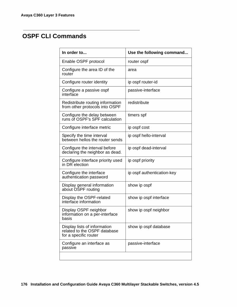
Avaya C360 Layer 3 Features
176 Installation and Configuration Guide Avaya C360 Multilayer Stackable Switches, version 4.5
OSPF CLI Commands
In order to... Use the following command...
Enable OSPF protocol router ospf
Configure the area ID of the router
area
Configure router identity ip ospf router-id
Configure a passive ospf interface
passive-interface
Redistribute routing information from other protocols into OSPF
redistribute
Configure the delay between runs of OSPF's SPF calculation
timers spf
Configure interface metric ip ospf cost
Specify the time interval between hellos the router sends
ip ospf hello-interval
Configure the interval before declaring the neighbor as dead.
ip ospf dead-interval
Configure interface priority used in DR election
ip ospf priority
Configure the interface authentication password
ip ospf authentication-key
Display general information about OSPF routing
show ip ospf
Display the OSPF-related interface information
show ip ospf interface
Display OSPF neighbor information on a per-interface basis
show ip ospf neighbor
Display lists of information related to the OSPF database for a specific router
show ip ospf database
Configure an interface as passive
passive-interface
Static Routing Configuration
Issue 2 July 2005 177
Static Routing Configuration
Static Routing OverviewWhen dynamic routing protocols (RIP or OSPF) are not appropriate, you can manually configure static routes to indicate the next hop on the path to the final packet destination.
A static route becomes inactive if the interface over which it is defined is disabled. When the interface is enabled, the static route becomes active again. They are never timed-out, or lost over reboot, and can only be removed by manual configuration. Deletion (by configuration) of the IP interface deletes the static routes using this interface as well.
Static routes can only be configured for remote destinations, i.e. destinations that are reachable via another router as a next hop. The next hop router must belong to one of the directly attached networks for which the C360 has an IP interface. "Local" static routes, such as those that have no next hop, are not allowed.
Two kinds of static routes can be configured:
● High Preference static routes which are preferred to routes learned from any routing protocol
● Low Preference static routes which are used temporarily until the route is learned from a routing protocol. By default, a static route has Low Preference.
Static routes can be advertised by routing protocols (i.e., RIP, OSPF) as described under Route redistribution.
Static routes also support load-balancing similar to OSPF. A static route can be configured with multiple next hops so that traffic is split between these next hops.
This can be used for example to load-balance traffic between several firewalls which serve as the default gateway.
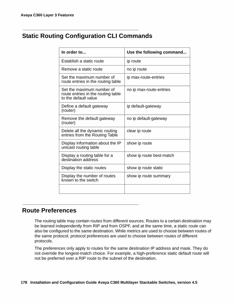
Avaya C360 Layer 3 Features
178 Installation and Configuration Guide Avaya C360 Multilayer Stackable Switches, version 4.5
Static Routing Configuration CLI Commands
Route PreferencesThe routing table may contain routes from different sources. Routes to a certain destination may be learned independently from RIP and from OSPF, and at the same time, a static route can also be configured to the same destination. While metrics are used to choose between routes of the same protocol, protocol preferences are used to choose between routes of different protocols.
The preferences only apply to routes for the same destination IP address and mask. They do not override the longest-match choice. For example, a high-preference static default route will not be preferred over a RIP route to the subnet of the destination.
In order to... Use the following command...
Establish a static route ip route
Remove a static route no ip route
Set the maximum number of route entries in the routing table
ip max-route-entries
Set the maximum number of route entries in the routing table to the default value
no ip max-route-entries
Define a default gateway (router)
ip default-gateway
Remove the default gateway (router)
no ip default-gateway
Delete all the dynamic routing entries from the Routing Table
clear ip route
Display information about the IP unicast routing table
show ip route
Display a routing table for a destination address
show ip route best-match
Display the static routes show ip route static
Display the number of routes known to the switch
show ip route summary
Static Routing Configuration
Issue 2 July 2005 179
C360 protocol preferences are listed below from the most to the least preferred:
1. Local (directly attached net)
2. High-preference static (manually configured routes)
3. OSPF internal routes
4. RIP
5. OSPF external routes
6. Low-preference static (manually configured routes).
Avaya C360 Layer 3 Features
180 Installation and Configuration Guide Avaya C360 Multilayer Stackable Switches, version 4.5
Route RedistributionRoute redistribution is the interaction of multiple routing protocols. OSPF and RIP can be operated concurrently in the C360. In this case, the C360 can be configured to redistribute routes learned from one protocol into the domain of the other routing protocol. Similarly, static routes may be redistributed to RIP and to OSPF. Route redistribution involves metric changes and sometimes causes routing loops in the presence of other routes with incompatible schemes for route redistribution and route preferences. Be careful!
The the C360 scheme for metric translation in route redistribution is as follows:
● Static to RIP metric configurable (default 1)
● OSPF internal metric N to RIP metric 1
● OSPF external type 1 metric N to RIP metric 1
● OSPF external type 2 metric N to RIP metric N+1
● Static to OSPF external type 2, metric configurable (default 1)
● RIP metric N to OSPF external type 2, metric N
● Direct to OSPF external type 2, metric 1.
By default, the C360 does not redistribute routes between OSPF and RIP. Redistribution from one protocol to the other can be configured. By default, static routes are not redistributed to RIP and OSPF. The C360 allows the user to globally enable redistribution of static routes to RIP, and separately, to globally enable redistribution of static routes to OSPF. In addition, the C360 lets the user configure, on a per static route basis, whether the route is to be redistributed to RIP and OSPF, and what metric (in the range of 1-15). The default state is to enable the route to be redistributed at metric 1. When static routes are redistributed to OSPF, they are always redistributed as external type 2.
Route Redistribution Commands
In order to... Use the following command...
Redistribute routing information from other protocols
redistribute
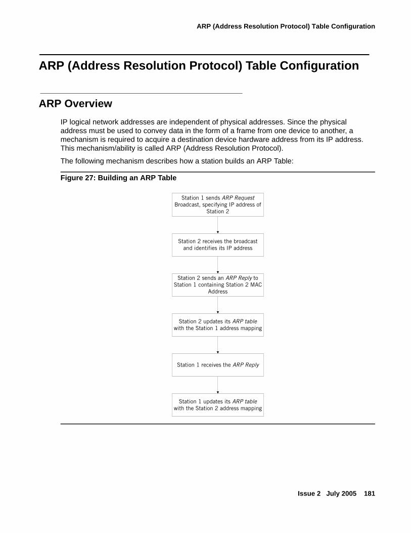
ARP (Address Resolution Protocol) Table Configuration
Issue 2 July 2005 181
ARP (Address Resolution Protocol) Table Configuration
ARP OverviewIP logical network addresses are independent of physical addresses. Since the physical address must be used to convey data in the form of a frame from one device to another, a mechanism is required to acquire a destination device hardware address from its IP address. This mechanism/ability is called ARP (Address Resolution Protocol).
The following mechanism describes how a station builds an ARP Table:
Figure 27: Building an ARP Table
Station 1 sends ARP RequestBroadcast, specifying IP address of
Station 2
Station 2 receives the broadcastand identifies its IP address
Station 2 sends an ARP Reply toStation 1 containing Station 2 MAC
Address
Station 2 updates its ARP tablewith the Station 1 address mapping
Station 1 receives the ARP Reply
Station 1 updates its ARP tablewith the Station 2 address mapping
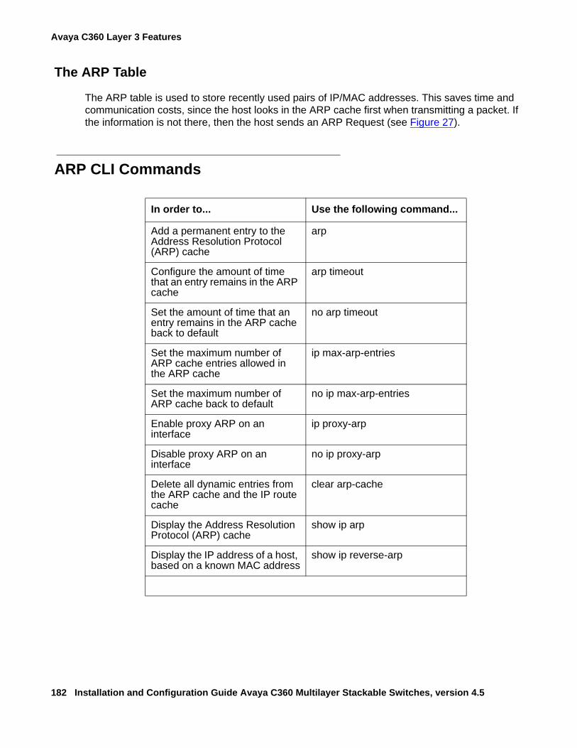
Avaya C360 Layer 3 Features
182 Installation and Configuration Guide Avaya C360 Multilayer Stackable Switches, version 4.5
The ARP Table
The ARP table is used to store recently used pairs of IP/MAC addresses. This saves time and communication costs, since the host looks in the ARP cache first when transmitting a packet. If the information is not there, then the host sends an ARP Request (see Figure 27).
ARP CLI Commands
In order to... Use the following command...
Add a permanent entry to the Address Resolution Protocol (ARP) cache
arp
Configure the amount of time that an entry remains in the ARP cache
arp timeout
Set the amount of time that an entry remains in the ARP cache back to default
no arp timeout
Set the maximum number of ARP cache entries allowed in the ARP cache
ip max-arp-entries
Set the maximum number of ARP cache back to default
no ip max-arp-entries
Enable proxy ARP on an interface
ip proxy-arp
Disable proxy ARP on an interface
no ip proxy-arp
Delete all dynamic entries from the ARP cache and the IP route cache
clear arp-cache
Display the Address Resolution Protocol (ARP) cache
show ip arp
Display the IP address of a host, based on a known MAC address
show ip reverse-arp
BOOTP/DHCP (Dynamic Host Configuration Protocol) Relay Configuration
Issue 2 July 2005 183
BOOTP/DHCP (Dynamic Host Configuration Protocol) Relay Configuration
BOOTP/DHCP Overview
BOOTP
Short for Bootstrap Protocol, BootP is an Internet protocol that enables a diskless workstation to discover its own IP address, the IP address of a BOOTP server on the network, and a file to be loaded into memory to boot the machine. This enables the workstation to boot without requiring a hard or floppy disk drive. It is used when the user/station location changes frequently.
The protocol is defined by RFC 951.
DHCP
Short for Dynamic Host Configuration Protocol, DHCP assigns dynamic IP addresses to devices on a network. With dynamic addressing, a device can have a different IP address every time it connects to the network. In some systems, the device's IP address can even change while it is still connected. DHCP also supports a mix of static and dynamic IP addresses.
Dynamic addressing simplifies network administration because the software keeps track of IP addresses rather than requiring an administrator to manage the task. This means that a new computer can be added to a network without the hassle of manually assigning it a unique IP address. Many ISPs use dynamic IP addressing for dial-up users. However, dynamic addressing may not be desirable for a network server.
DHCP/BOOTP Relay
The C360 supports the DHCP/BOOTP Relay Agent function. This is an application that accepts DHCP/BOOTP requests that are broadcast on one VLAN and sends them to a DHCP/BOOTP server that connects to another VLAN or a server that may be located across one or more routers that would otherwise not get the broadcast request. The relay agent handles the DHCP/BOOTP replies as well, transmitting them to the client directly or as broadcast, according to a flag in the reply message. Note that the same DHCP/BOOTP relay agent serves both the BOOTP and DHCP protocols.
When there is more than one IP interface on a VLAN, the C360 automatically chooses one of the IP interface's to determine the relay network. Alternatively, you can configure the relay networks that the C360 will use. If you have defined more than one network, the C360 selects the network to be relayed on a Round Robin basis.
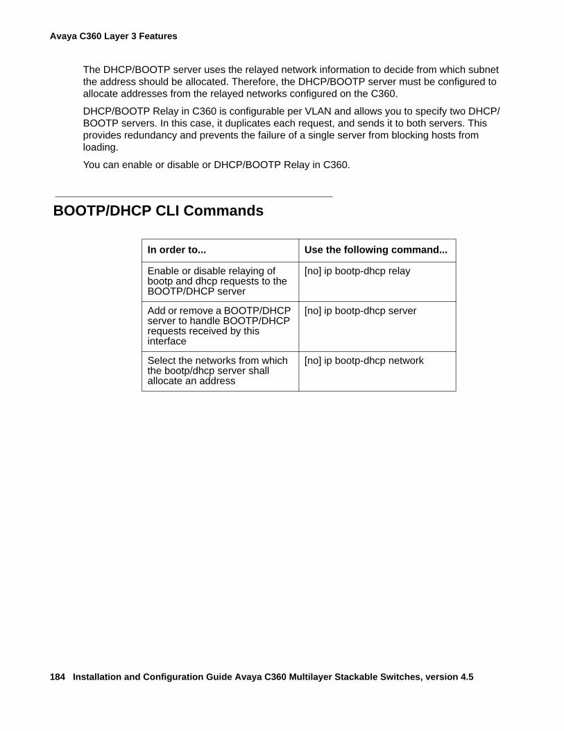
Avaya C360 Layer 3 Features
184 Installation and Configuration Guide Avaya C360 Multilayer Stackable Switches, version 4.5
The DHCP/BOOTP server uses the relayed network information to decide from which subnet the address should be allocated. Therefore, the DHCP/BOOTP server must be configured to allocate addresses from the relayed networks configured on the C360.
DHCP/BOOTP Relay in C360 is configurable per VLAN and allows you to specify two DHCP/BOOTP servers. In this case, it duplicates each request, and sends it to both servers. This provides redundancy and prevents the failure of a single server from blocking hosts from loading.
You can enable or disable or DHCP/BOOTP Relay in C360.
BOOTP/DHCP CLI Commands
In order to... Use the following command...
Enable or disable relaying of bootp and dhcp requests to the BOOTP/DHCP server
[no] ip bootp-dhcp relay
Add or remove a BOOTP/DHCP server to handle BOOTP/DHCP requests received by this interface
[no] ip bootp-dhcp server
Select the networks from which the bootp/dhcp server shall allocate an address
[no] ip bootp-dhcp network
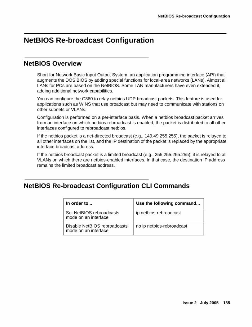
NetBIOS Re-broadcast Configuration
Issue 2 July 2005 185
NetBIOS Re-broadcast Configuration
NetBIOS OverviewShort for Network Basic Input Output System, an application programming interface (API) that augments the DOS BIOS by adding special functions for local-area networks (LANs). Almost all LANs for PCs are based on the NetBIOS. Some LAN manufacturers have even extended it, adding additional network capabilities.
You can configure the C360 to relay netbios UDP broadcast packets. This feature is used for applications such as WINS that use broadcast but may need to communicate with stations on other subnets or VLANs.
Configuration is performed on a per-interface basis. When a netbios broadcast packet arrives from an interface on which netbios rebroadcast is enabled, the packet is distributed to all other interfaces configured to rebroadcast netbios.
If the netbios packet is a net-directed broadcast (e.g., 149.49.255.255), the packet is relayed to all other interfaces on the list, and the IP destination of the packet is replaced by the appropriate interface broadcast address.
If the netbios broadcast packet is a limited broadcast (e.g., 255.255.255.255), it is relayed to all VLANs on which there are netbios-enabled interfaces. In that case, the destination IP address remains the limited broadcast address.
NetBIOS Re-broadcast Configuration CLI Commands
In order to... Use the following command...
Set NetBIOS rebroadcasts mode on an interface
ip netbios-rebroadcast
Disable NetBIOS rebroadcasts mode on an interface
no ip netbios-rebroadcast
Avaya C360 Layer 3 Features
186 Installation and Configuration Guide Avaya C360 Multilayer Stackable Switches, version 4.5
VRRP (Virtual Router Redundancy Protocol) Configuration
VRRP OverviewVRRP is an IETF protocol designed to support redundancy of routers on the LAN, as well as load balancing of traffic. VRRP is transparent to host stations, making it an ideal choice when redundancy, load balancing and ease of configuration are all required.
The concept underlying VRRP is that a router can backup other routers, in addition to performing its primary routing functions. This redundancy is achieved by introducing a virtual router. A virtual router is a routing entity associated with multiple physical routers. The routing functions of the virtual router are performed by one of the physical routers with which it is associated. This router is known as the master router. For each virtual router, VRRP selects a master router. If the selected master router fails, another router is selected as master router.
In VRRP, two or more physical routers can be associated with a virtual router, thus achieving extreme reliability. In a VRRP environment, host stations interact with the virtual router. They are not aware that this router is a virtual router, and they are not affected when a new router takes over the role of master router. This makes VRRP fully interoperable with every host station.
VRRP can be activated on an interface using a single command while allowing for the necessary fine-tuning of the many VRRP parameters. For a detailed description of VRRP, refer to VRRP standards and published literature.
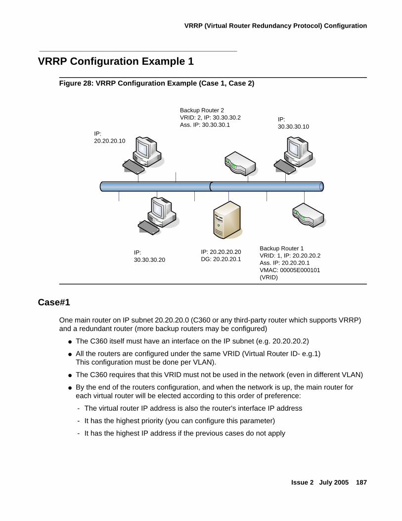
VRRP (Virtual Router Redundancy Protocol) Configuration
Issue 2 July 2005 187
VRRP Configuration Example 1
Figure 28: VRRP Configuration Example (Case 1, Case 2)
Case#1
One main router on IP subnet 20.20.20.0 (C360 or any third-party router which supports VRRP) and a redundant router (more backup routers may be configured)
● The C360 itself must have an interface on the IP subnet (e.g. 20.20.20.2)
● All the routers are configured under the same VRID (Virtual Router ID- e.g.1)This configuration must be done per VLAN).
● The C360 requires that this VRID must not be used in the network (even in different VLAN)
● By the end of the routers configuration, and when the network is up, the main router for each virtual router will be elected according to this order of preference:
- The virtual router IP address is also the router's interface IP address
- It has the highest priority (you can configure this parameter)
- It has the highest IP address if the previous cases do not apply
``
`
Backup Router 1VRID: 1, IP: 20.20.20.2Ass. IP: 20.20.20.1VMAC: 00005E000101 (VRID)
Backup Router 2VRID: 2, IP: 30.30.30.2Ass. IP: 30.30.30.1
IP: 30.30.30.20
IP: 20.20.20.10
IP: 20.20.20.20DG: 20.20.20.1
IP: 30.30.30.10
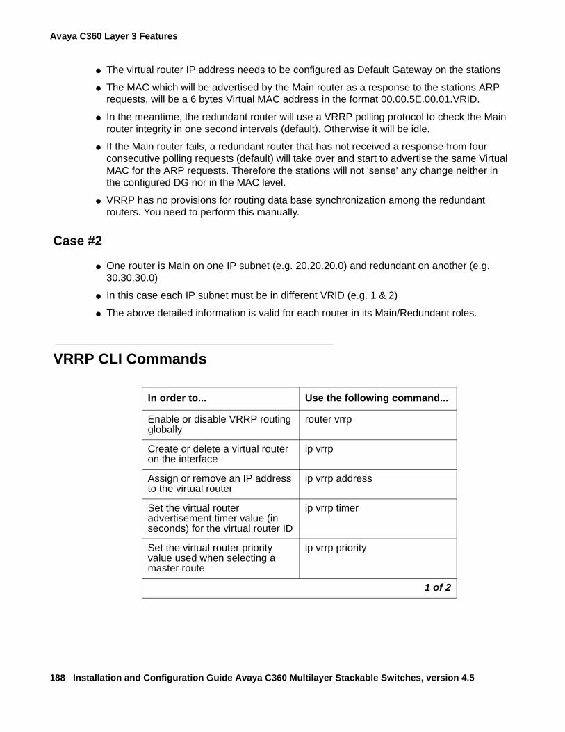
Avaya C360 Layer 3 Features
188 Installation and Configuration Guide Avaya C360 Multilayer Stackable Switches, version 4.5
● The virtual router IP address needs to be configured as Default Gateway on the stations
● The MAC which will be advertised by the Main router as a response to the stations ARP requests, will be a 6 bytes Virtual MAC address in the format 00.00.5E.00.01.VRID.
● In the meantime, the redundant router will use a VRRP polling protocol to check the Main router integrity in one second intervals (default). Otherwise it will be idle.
● If the Main router fails, a redundant router that has not received a response from four consecutive polling requests (default) will take over and start to advertise the same Virtual MAC for the ARP requests. Therefore the stations will not 'sense' any change neither in the configured DG nor in the MAC level.
● VRRP has no provisions for routing data base synchronization among the redundant routers. You need to perform this manually.
Case #2
● One router is Main on one IP subnet (e.g. 20.20.20.0) and redundant on another (e.g. 30.30.30.0)
● In this case each IP subnet must be in different VRID (e.g. 1 & 2)
● The above detailed information is valid for each router in its Main/Redundant roles.
VRRP CLI Commands
In order to... Use the following command...
Enable or disable VRRP routing globally
router vrrp
Create or delete a virtual router on the interface
ip vrrp
Assign or remove an IP address to the virtual router
ip vrrp address
Set the virtual router advertisement timer value (in seconds) for the virtual router ID
ip vrrp timer
Set the virtual router priority value used when selecting a master route
ip vrrp priority
1 of 2
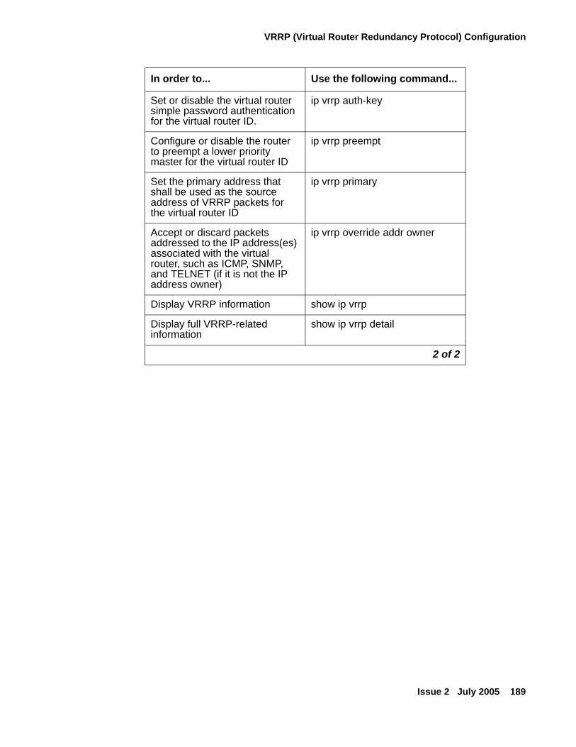
VRRP (Virtual Router Redundancy Protocol) Configuration
Issue 2 July 2005 189
Set or disable the virtual router simple password authentication for the virtual router ID.
ip vrrp auth-key
Configure or disable the router to preempt a lower priority master for the virtual router ID
ip vrrp preempt
Set the primary address that shall be used as the source address of VRRP packets for the virtual router ID
ip vrrp primary
Accept or discard packets addressed to the IP address(es) associated with the virtual router, such as ICMP, SNMP, and TELNET (if it is not the IP address owner)
ip vrrp override addr owner
Display VRRP information show ip vrrp
Display full VRRP-related information
show ip vrrp detail
In order to... Use the following command...
2 of 2
Avaya C360 Layer 3 Features
190 Installation and Configuration Guide Avaya C360 Multilayer Stackable Switches, version 4.5
Policy Configuration
Policy Configuration OverviewThe C360 supports QoS (Quality of Service) by using multiple priority levels and IEEE 802.1p priority tagging to ensure that data and voice receive the necessary levels of service.
The C360 can enforce QoS policy on routed packets and change their 802.1p priority, according to the following criteria:
● The packet protocol
● Matching the packet's source or destination IP address to the configured priority policy.
● Whether the packet source or destination TCP/UDP port number falls within a pre-defined range.
In addition, the 802.1p priority of a packet can be modified according to the DSCP value in the IP header based on the DSCP-802.1p mapping configured by the user.
The C360 supports Access Control policy. Access Control rules define how the C360 should handle routed packets. There are three possible ways to handle such packets:
● Forward the packet (Permit operation)
● Discard the packet (Deny operation)
● Discard the packet and notify the management station (Deny and Notify)
The C360 can enforce Access Control policy on each routed packet, according to the following criteria:
● Matching the packet's source or destination IP address to the configured Access Control policy.
● Determine if the packet protocol and source or destination TCP/UDP port number falls within a pre-defined range.
● Using the ACK bit of the TCP header.
The C360 uses policy lists containing both Access Control rules and QoS rules. The policy lists are ordered by rule indexing.
Tip:Tip: Use the Command Line Interface and the Avaya central policy management
application under Avaya Integrated Management to set up the C360 access control rules
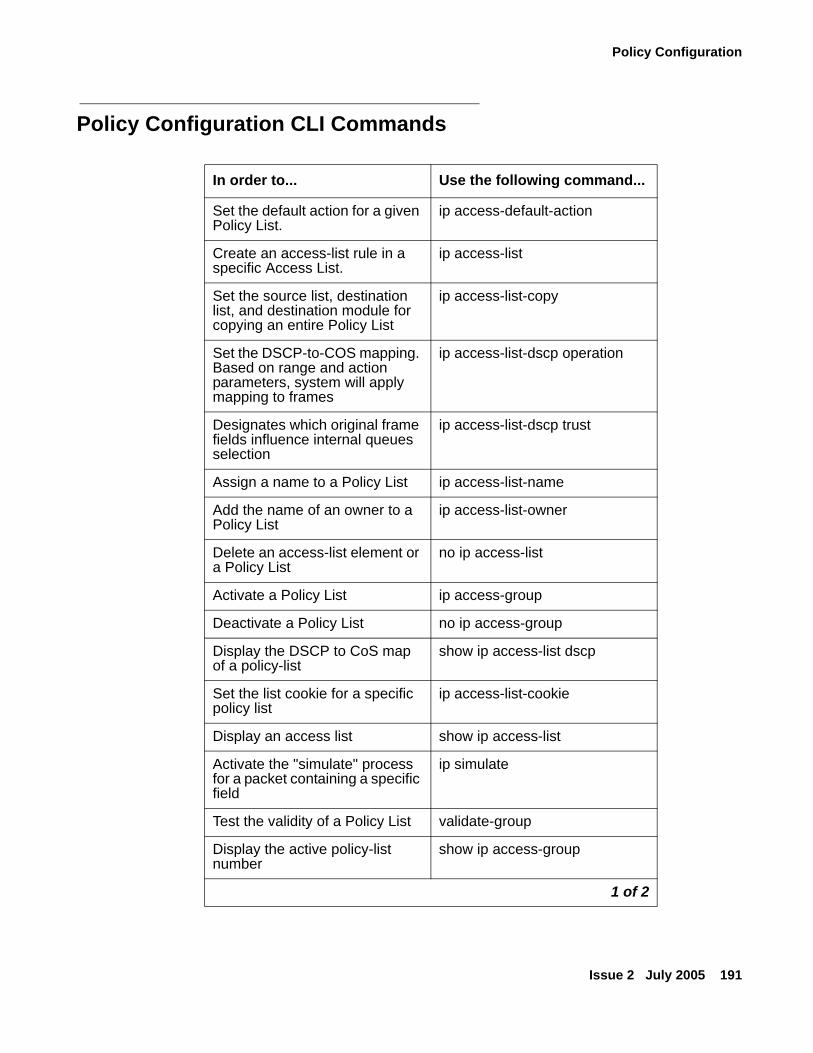
Policy Configuration
Issue 2 July 2005 191
Policy Configuration CLI Commands
In order to... Use the following command...
Set the default action for a given Policy List.
ip access-default-action
Create an access-list rule in a specific Access List.
ip access-list
Set the source list, destination list, and destination module for copying an entire Policy List
ip access-list-copy
Set the DSCP-to-COS mapping. Based on range and action parameters, system will apply mapping to frames
ip access-list-dscp operation
Designates which original frame fields influence internal queues selection
ip access-list-dscp trust
Assign a name to a Policy List ip access-list-name
Add the name of an owner to a Policy List
ip access-list-owner
Delete an access-list element or a Policy List
no ip access-list
Activate a Policy List ip access-group
Deactivate a Policy List no ip access-group
Display the DSCP to CoS map of a policy-list
show ip access-list dscp
Set the list cookie for a specific policy list
ip access-list-cookie
Display an access list show ip access-list
Activate the "simulate" process for a packet containing a specific field
ip simulate
Test the validity of a Policy List validate-group
Display the active policy-list number
show ip access-group
1 of 2
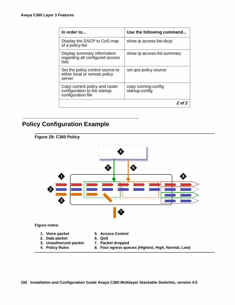
Avaya C360 Layer 3 Features
192 Installation and Configuration Guide Avaya C360 Multilayer Stackable Switches, version 4.5
Policy Configuration Example
Figure 29: C360 Policy
Display the DSCP to CoS map of a policy-list
show ip access-list-dscp
Display summary information regarding all configured access lists
show ip-access-list-summary
Set the policy control source to either local or remote policy server
set qos policy source
Copy current policy and router configuration to the startup configuration file
copy running-config startup-config
In order to... Use the following command...
2 of 2
Figure notes:
1. Voice packet2. Data packet3. Unauthorized packet4. Policy Rules
5. Access Control6. QoS7. Packet dropped8. Four egress queues (Highest, High, Normal, Low)
1
2
3
4
5 6
7
8
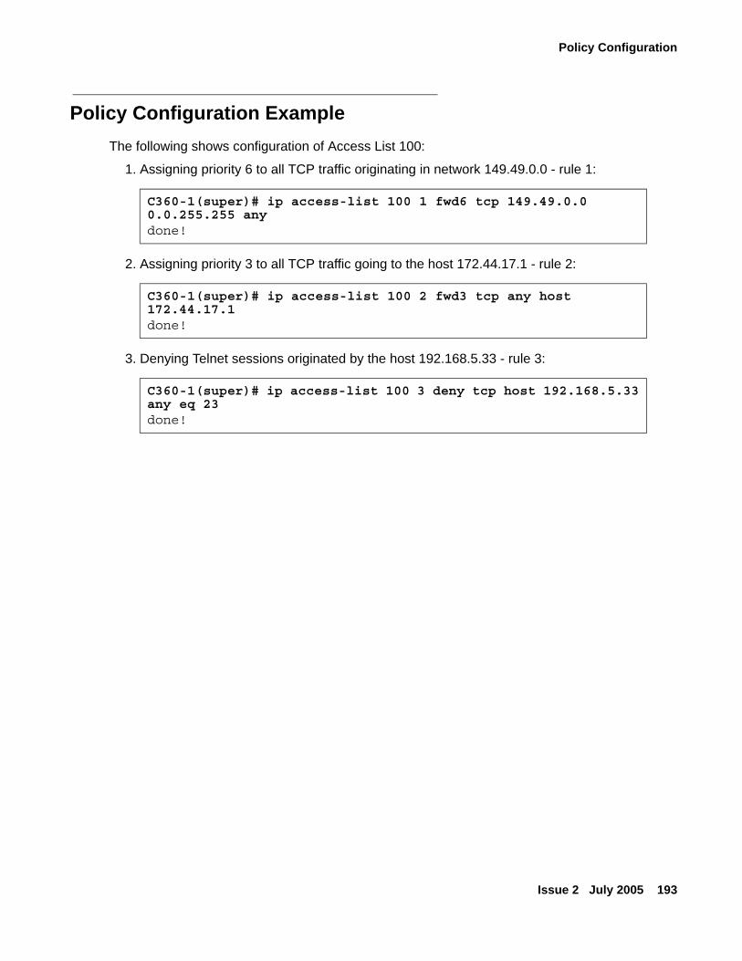
Policy Configuration
Issue 2 July 2005 193
Policy Configuration ExampleThe following shows configuration of Access List 100:
1. Assigning priority 6 to all TCP traffic originating in network 149.49.0.0 - rule 1:
2. Assigning priority 3 to all TCP traffic going to the host 172.44.17.1 - rule 2:
3. Denying Telnet sessions originated by the host 192.168.5.33 - rule 3:
C360-1(super)# ip access-list 100 1 fwd6 tcp 149.49.0.0 0.0.255.255 any done!
C360-1(super)# ip access-list 100 2 fwd3 tcp any host 172.44.17.1done!
C360-1(super)# ip access-list 100 3 deny tcp host 192.168.5.33 any eq 23done!
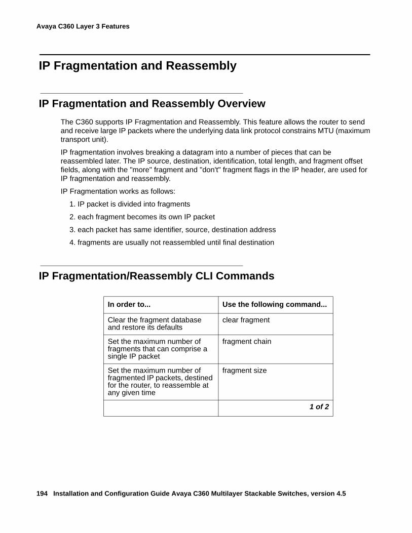
Avaya C360 Layer 3 Features
194 Installation and Configuration Guide Avaya C360 Multilayer Stackable Switches, version 4.5
IP Fragmentation and Reassembly
IP Fragmentation and Reassembly Overview The C360 supports IP Fragmentation and Reassembly. This feature allows the router to send and receive large IP packets where the underlying data link protocol constrains MTU (maximum transport unit).
IP fragmentation involves breaking a datagram into a number of pieces that can be reassembled later. The IP source, destination, identification, total length, and fragment offset fields, along with the "more" fragment and "don't" fragment flags in the IP header, are used for IP fragmentation and reassembly.
IP Fragmentation works as follows:
1. IP packet is divided into fragments
2. each fragment becomes its own IP packet
3. each packet has same identifier, source, destination address
4. fragments are usually not reassembled until final destination
IP Fragmentation/Reassembly CLI Commands
In order to... Use the following command...
Clear the fragment database and restore its defaults
clear fragment
Set the maximum number of fragments that can comprise a single IP packet
fragment chain
Set the maximum number of fragmented IP packets, destined for the router, to reassemble at any given time
fragment size
1 of 2

IP Fragmentation and Reassembly
Issue 2 July 2005 195
Set the maximum number of seconds to reassemble a fragmented IP packet destined for the router.
fragment timeout
Display information regarding fragmented IP packets that are destined for the router
show fragment
In order to... Use the following command...
2 of 2

Avaya C360 Layer 3 Features
196 Installation and Configuration Guide Avaya C360 Multilayer Stackable Switches, version 4.5
Issue 2 July 2005 197
Chapter 10: Avaya C360 Power over Ethernet Features
This chapter describes the C360-PWR PoE (Power over Ethernet Features). It provides the basic procedures for configuring the C360 for PoE operation.
It contains the following sections:
● Load Detection
● “Plug and Play" Operation
● Powering Devices
● Power over Ethernet in Converged Networks
● Power over Ethernet CLI Commands
Avaya C360 Power over Ethernet Features
198 Installation and Configuration Guide Avaya C360 Multilayer Stackable Switches, version 4.5
Power Over EthernetThe C360-PWR switches provides IEEE 802.3af-compliant "Inline" DC power over the signal pairs in addition to switched Ethernet on the existing LAN infrastructure for devices such as IP telephones and Wireless LAN access points. This allows you to deploy devices in the network that require power without installing standard power cables in hard to access areas. The C360-PWR switches are pre-configured to supply power according to the load detection criteria (see Load Detection), so you can use it right out of the box. The C360-PWR switches provide power over standard Category 3 and Category 5 cables.
Load DetectionThe C360-PWR switches periodically check all ports, powered and non-powered to check their status and the power status of connected devices.
The C360-PWR switches will supply power to a port only after it has detected a suitable PD (powered device) is connected to the port. The check consists of the C360-PWR switches looking for a signature from the device that indicates it needs to supply power.
How the C360-PWR Switches Detect a Powered Device
The C360-PWR switches use the specific resistance powered device signature and PD (powered device) connection verification to determine whether to supply power to a give port. Figure 30 shows the process.
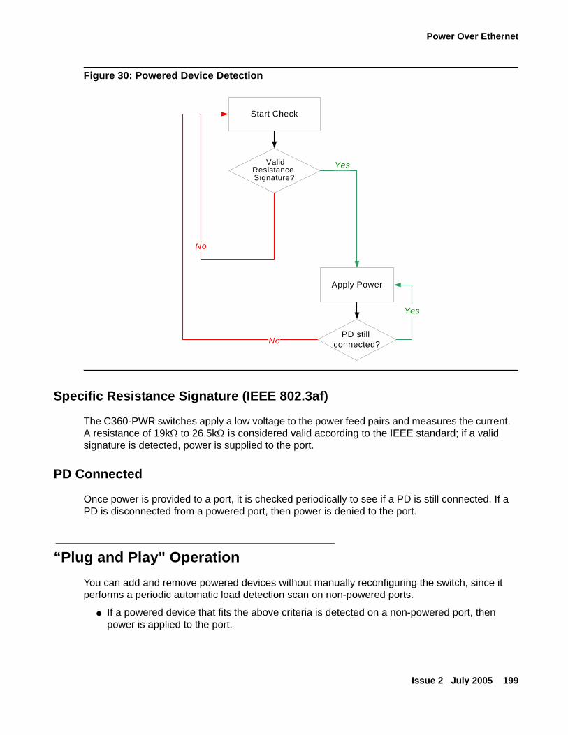
Power Over Ethernet
Issue 2 July 2005 199
Figure 30: Powered Device Detection
Specific Resistance Signature (IEEE 802.3af)
The C360-PWR switches apply a low voltage to the power feed pairs and measures the current. A resistance of 19kΩ to 26.5kΩ is considered valid according to the IEEE standard; if a valid signature is detected, power is supplied to the port.
PD Connected
Once power is provided to a port, it is checked periodically to see if a PD is still connected. If a PD is disconnected from a powered port, then power is denied to the port.
“Plug and Play" OperationYou can add and remove powered devices without manually reconfiguring the switch, since it performs a periodic automatic load detection scan on non-powered ports.
● If a powered device that fits the above criteria is detected on a non-powered port, then power is applied to the port.
Start Check
Apply Power
Yes
No
No
Yes
PD still connected?
ValidResistance Signature?
Avaya C360 Power over Ethernet Features
200 Installation and Configuration Guide Avaya C360 Multilayer Stackable Switches, version 4.5
● If a powered device is removed from a port, then power is denied to that port. The disconnected port is then scanned as well.
Powering DevicesThe C360 ports can receive Inline power from one of two sources: an internal -48VDC power supply or an external DC power supply.
Each port can supply up to 15.4W by default to the powered device.
The internal power supply delivers a maximum of 305W for all the ports on the C363T-PWR and 520W on the C364T-PWR.
If a powered device tries to draw more than the maximum allowed for the connected port, power is denied and you receive an "overcurrent" warning. Similarly, if the power drops below the lower limit, for a port, power is denied to that port and an "undercurrent" warning is issued.
Priority
Since the internal power supply may not be capable of driving powered devices on all the ports simultaneously, Avaya has implemented a priority mechanism.
This mechanism determines the order in which ports are powered after the switch is booted and powered down if the power resources of the switch are exhausted.
There are three user-configurable priority levels:
● Low
● High
● Critical
The default value is "Low" for all ports.
Within these levels, priority is according to port number: the lower the port number, the higher the priority.
Power will automatically be restored to PDs according to their priority when the power budget increases. If the power budget is exceeded, power will not be provided to a new PD when you attach it, even if you define its priority as "High" or "Critical."
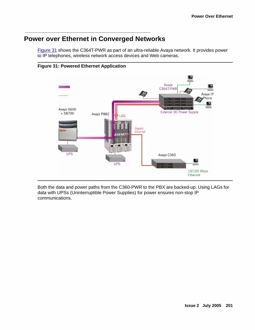
Power Over Ethernet
Issue 2 July 2005 201
Power over Ethernet in Converged NetworksFigure 31 shows the C364T-PWR as part of an ultra-reliable Avaya network. It provides power to IP telephones, wireless network access devices and Web cameras.
Figure 31: Powered Ethernet Application
Both the data and power paths from the C360-PWR to the PBX are backed-up. Using LAGs for data with UPSs (Uninterruptible Power Supplies) for power ensures non-stop IP communications.
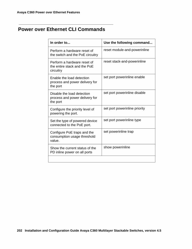
Avaya C360 Power over Ethernet Features
202 Installation and Configuration Guide Avaya C360 Multilayer Stackable Switches, version 4.5
Power over Ethernet CLI Commands
In order to... Use the following command...
Perform a hardware reset of the switch and the PoE circuitry
reset module-and-powerinline
Perform a hardware reset of the entire stack and the PoE circuitry
reset stack-and-powerinline
Enable the load detection process and power delivery for the port
set port powerinline enable
Disable the load detection process and power delivery for the port
set port powerinline disable
Configure the priority level of powering the port.
set port powerinline priority
Set the type of powered device connected to the PoE port.
set port powerinline type
Configure PoE traps and the consumption usage threshold value.
set powerinline trap
Show the current status of the PD inline power on all ports
show powerinline
Issue 1 June 2005 203
Chapter 11: C360 Device Manager
This chapter describes the installation procedures for the C360 Device Manager
OverviewThe Device Manager provides the following:
● Managing and monitoring Power over Ethernet.
● Device Configuration - Viewing and modifying the different device configurations.
● Virtual LANs - Viewing and editing Virtual LAN information.
● Link Aggregation Groups (LAGs) - Viewing and editing LAG information.
● Port Redundancy - Setting port redundancy for ports in a C360 Switch.
● Port Mirroring - Setting up port mirroring for ports in a C360 Switch.
● Trap Managers Configuration - Viewing and modifying the Trap Managers Table.
● Switch Connected Addresses - View devices connected to selected ports. Port Security.
● Intermodule Redundancy
● One pair per stack.
● Also operates as a result of a module fault, for example, power failure.
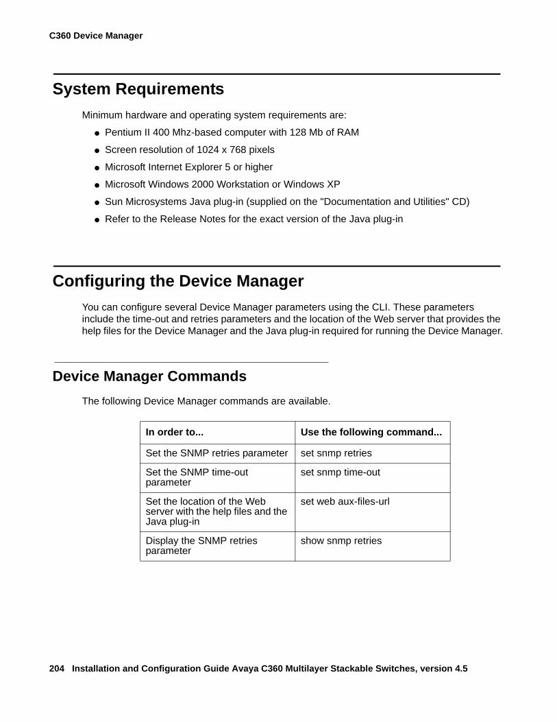
C360 Device Manager
204 Installation and Configuration Guide Avaya C360 Multilayer Stackable Switches, version 4.5
System RequirementsMinimum hardware and operating system requirements are:
● Pentium II 400 Mhz-based computer with 128 Mb of RAM
● Screen resolution of 1024 x 768 pixels
● Microsoft Internet Explorer 5 or higher
● Microsoft Windows 2000 Workstation or Windows XP
● Sun Microsystems Java plug-in (supplied on the "Documentation and Utilities" CD)
● Refer to the Release Notes for the exact version of the Java plug-in
Configuring the Device ManagerYou can configure several Device Manager parameters using the CLI. These parameters include the time-out and retries parameters and the location of the Web server that provides the help files for the Device Manager and the Java plug-in required for running the Device Manager.
Device Manager CommandsThe following Device Manager commands are available.
In order to... Use the following command...
Set the SNMP retries parameter set snmp retries
Set the SNMP time-out parameter
set snmp time-out
Set the location of the Web server with the help files and the Java plug-in
set web aux-files-url
Display the SNMP retries parameter
show snmp retries
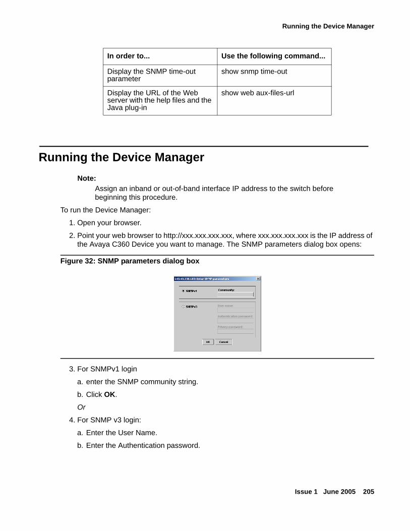
Running the Device Manager
Issue 1 June 2005 205
Running the Device ManagerNote:
Note: Assign an inband or out-of-band interface IP address to the switch before beginning this procedure.
To run the Device Manager:
1. Open your browser.
2. Point your web browser to http://xxx.xxx.xxx.xxx, where xxx.xxx.xxx.xxx is the IP address of the Avaya C360 Device you want to manage. The SNMP parameters dialog box opens:
Figure 32: SNMP parameters dialog box
3. For SNMPv1 login
a. enter the SNMP community string.
b. Click OK.
Or
4. For SNMP v3 login:
a. Enter the User Name.
b. Enter the Authentication password.
Display the SNMP time-out parameter
show snmp time-out
Display the URL of the Web server with the help files and the Java plug-in
show web aux-files-url
In order to... Use the following command...
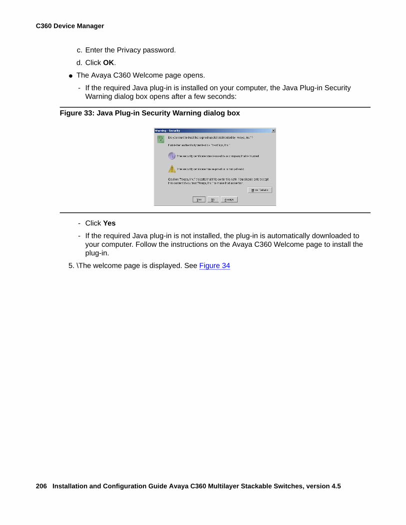
C360 Device Manager
206 Installation and Configuration Guide Avaya C360 Multilayer Stackable Switches, version 4.5
c. Enter the Privacy password.
d. Click OK.
● The Avaya C360 Welcome page opens.
- If the required Java plug-in is installed on your computer, the Java Plug-in Security Warning dialog box opens after a few seconds:
Figure 33: Java Plug-in Security Warning dialog box
- Click Yes- If the required Java plug-in is not installed, the plug-in is automatically downloaded to
your computer. Follow the instructions on the Avaya C360 Welcome page to install the plug-in.
5. \The welcome page is displayed. See Figure 34
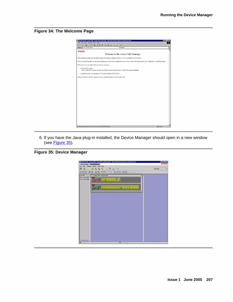
Running the Device Manager
Issue 1 June 2005 207
Figure 34: The Welcome Page
6. If you have the Java plug-in installed, the Device Manager should open in a new window (see Figure 35).
Figure 35: Device Manager
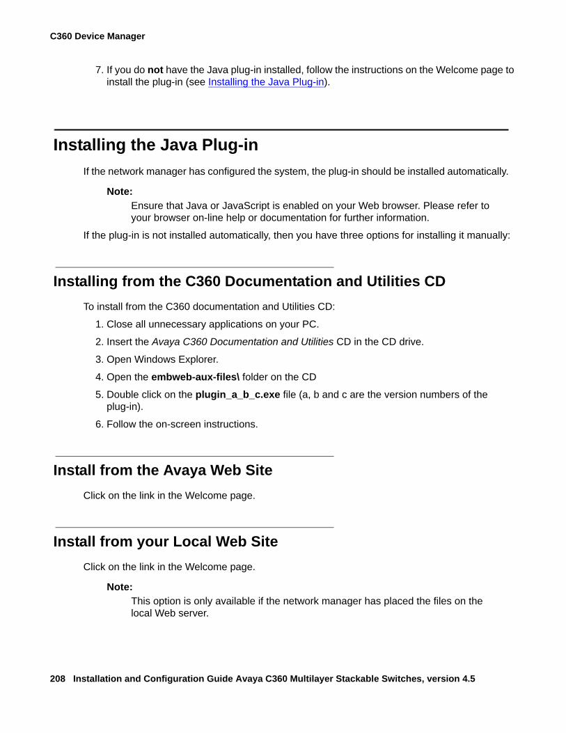
C360 Device Manager
208 Installation and Configuration Guide Avaya C360 Multilayer Stackable Switches, version 4.5
7. If you do not have the Java plug-in installed, follow the instructions on the Welcome page to install the plug-in (see Installing the Java Plug-in).
Installing the Java Plug-inIf the network manager has configured the system, the plug-in should be installed automatically.
Note:Note: Ensure that Java or JavaScript is enabled on your Web browser. Please refer to
your browser on-line help or documentation for further information.
If the plug-in is not installed automatically, then you have three options for installing it manually:
Installing from the C360 Documentation and Utilities CDTo install from the C360 documentation and Utilities CD:
1. Close all unnecessary applications on your PC.
2. Insert the Avaya C360 Documentation and Utilities CD in the CD drive.
3. Open Windows Explorer.
4. Open the embweb-aux-files\ folder on the CD
5. Double click on the plugin_a_b_c.exe file (a, b and c are the version numbers of the plug-in).
6. Follow the on-screen instructions.
Install from the Avaya Web SiteClick on the link in the Welcome page.
Install from your Local Web SiteClick on the link in the Welcome page.
Note:Note: This option is only available if the network manager has placed the files on the
local Web server.
Installing the On-Line Help and Java Plug-In on your Web Site
Issue 1 June 2005 209
Installing the On-Line Help and Java Plug-In on your Web Site
Tip:Tip: This procedure is optional
Copying the help files and Java plug-in to a local Web server allows users to access the on-line help for the Embedded Manager and enables automatic Installation and Maintenance of the Java plug-in the first time the users tries to manage the device.
1. Copy the emweb-aux-files directory from the Avaya C360 Documentation and Utilities CD to your local Web server. Please refer to your Web server documentation for full instructions.
2. Define the URL in the C360 using the following CLI command:set web aux-files-url //IP address/directory name where //IP address/directory name is the location of the directory from the previous step.
DocumentationThe Device Manager comes with a detailed User's Guide including a Glossary of Terms and an overview of Data Communications concepts.

C360 Device Manager
210 Installation and Configuration Guide Avaya C360 Multilayer Stackable Switches, version 4.5

Issue 2 July 2005 211
Section 4: Troubleshooting and Maintaining the Avaya C360

212 Installation and Configuration Guide Avaya C360 Multilayer Stackable Switches, version 4.5
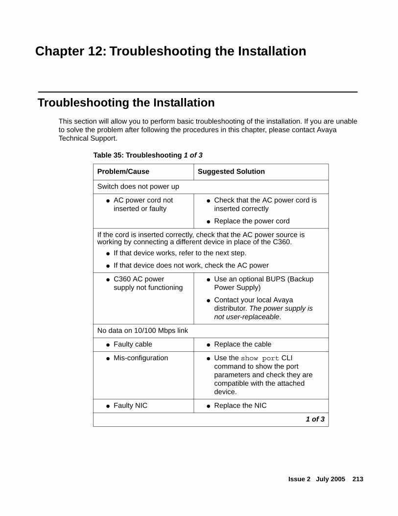
Issue 2 July 2005 213
Chapter 12: Troubleshooting the Installation
Troubleshooting the Installation This section will allow you to perform basic troubleshooting of the installation. If you are unable to solve the problem after following the procedures in this chapter, please contact Avaya Technical Support.
Table 35: Troubleshooting 1 of 3
Problem/Cause Suggested Solution
Switch does not power up
● AC power cord not inserted or faulty
● Check that the AC power cord is inserted correctly
● Replace the power cord
If the cord is inserted correctly, check that the AC power source is working by connecting a different device in place of the C360.
● If that device works, refer to the next step.
● If that device does not work, check the AC power
● C360 AC power supply not functioning
● Use an optional BUPS (Backup Power Supply)
● Contact your local Avaya distributor. The power supply is not user-replaceable.
No data on 10/100 Mbps link
● Faulty cable ● Replace the cable
● Mis-configuration ● Use the show port CLI command to show the port parameters and check they are compatible with the attached device.
● Faulty NIC ● Replace the NIC
1 of 3
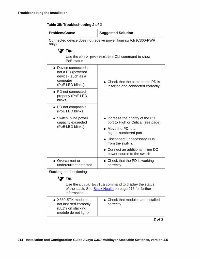
Troubleshooting the Installation
214 Installation and Configuration Guide Avaya C360 Multilayer Stackable Switches, version 4.5
Connected device does not receive power from switch (C360-PWR only)
Tip:Tip: Use the show powerinline CLI command to show
PoE status
● Device connected is not a PD (powered device), such as a computer(PoE LED blinks)
● Check that the cable to the PD is inserted and connected correctly
● PD not connected properly (PoE LED blinks)
● PD not compatible(PoE LED blinks)
● Switch Inline power capacity exceeded(PoE LED blinks)
● Increase the priority of the PD port to High or Critical (see page)
● Move the PD to a higher-numbered port
● Disconnect unnecessary PDs from the switch.
● Connect an additional Inline DC power source to the switch
● Overcurrent or undercurrent detected.
● Check that the PD is working correctly.
Stacking not functioning
Tip:Tip: Use the stack health command to display the status
of the stack. See Stack Health on page 216 for further information.
● X360-STK modules not inserted correctly(LEDs on stacking module do not light)
● Check that modules are installed correctly
Table 35: Troubleshooting 2 of 3
Problem/Cause Suggested Solution
2 of 3
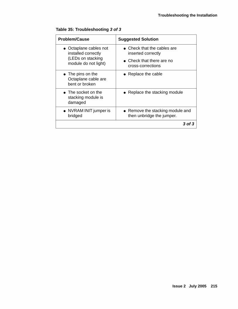
Troubleshooting the Installation
Issue 2 July 2005 215
● Octaplane cables not installed correctly(LEDs on stacking module do not light)
● Check that the cables are inserted correctly
● Check that there are no cross-corrections
● The pins on the Octaplane cable are bent or broken
● Replace the cable
● The socket on the stacking module is damaged
● Replace the stacking module
● NVRAM INIT jumper is bridged
● Remove the stacking module and then unbridge the jumper.
Table 35: Troubleshooting 3 of 3
Problem/Cause Suggested Solution
3 of 3
Troubleshooting the Installation
216 Installation and Configuration Guide Avaya C360 Multilayer Stackable Switches, version 4.5
Stack HealthThe C360 software provides a Stack Health feature for verifying the integrity of the C360 and P330 and P330-ML stacking module and cables.
OverviewThe Stack Health feature will identify defective modules and cables that may be installed in the C360 stack. The Stack Health algorithm separately checks all stacking modules and the Octaplane connections (including Redundant cable).
Implementation of Stack Health in the C360When activating the Stack Health feature, the agents in all modules start sending special packets of various length via all stacking cables to one another. The Master module synchronizes this process and collects the results.
● When the Redundant Cable is present, the user is prompted to disconnect one of the short Octaplane cables and the redundant connection will be checked. Then, when prompted, the cable should be reconnected and the test will run a second time to check the regular Octaplane connections.
● The stack is reset after the Stack Health process completes.
Tip:Tip: You should not load the stack with traffic during this test.
Tip:Tip: If the stack health process fails, try to fasten or replace the stack cable between
the modules where the failure has occurred. If the problem persists, try to fasten or replace either or both of the stacking modules.
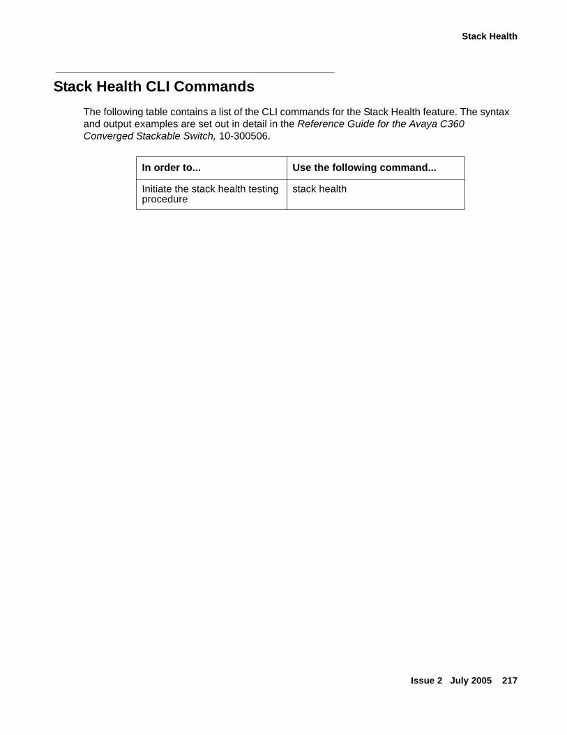
Stack Health
Issue 2 July 2005 217
Stack Health CLI CommandsThe following table contains a list of the CLI commands for the Stack Health feature. The syntax and output examples are set out in detail in the Reference Guide for the Avaya C360 Converged Stackable Switch, 10-300506.
In order to... Use the following command...
Initiate the stack health testing procedure
stack health

Troubleshooting the Installation
218 Installation and Configuration Guide Avaya C360 Multilayer Stackable Switches, version 4.5
Issue 2 July 2005 219
Chapter 13: Maintenance
IntroductionThis section provides basic maintenance information for the C360 and its components. For issues that are not covered in this chapter or in Chapter 12: Troubleshooting the Installation please contact your Avaya representative.
! CAUTION:CAUTION: Please refer to Before you Install the Avaya C360 before undertaking any of the
procedures detailed in this section.
Replacing the Stacking ModuleTo replace the X360STK stacking module:
1. Power to the switch may remain on.
2. Loosen the screws to the stacking module by turning the knurled knobs anti-clockwise.
3. Take hold of the two knobs (one near each side of the front panel) and pull gently but firmly towards yourself.
4. Insert the new stacking module gently into the slot, ensuring that the PCB (printed circuit board) is aligned with the guide rails.
5. Press the stacking module in firmly until it is completely inserted into the C360.
! CAUTION:CAUTION: Ensure that the screws on the module are properly aligned with the holes in the
chassis before tightening them.
! CAUTION:CAUTION: To prevent EMI, cover any unused ports on the stacking modules using the grey
plugs provided. Insert the plug labelled "left" into the lower port; insert the plug labelled "right" into the upper port.
6. Tighten the two screws on the side panel of the stacking module by turning the knurled knobs clockwise.
Maintenance
220 Installation and Configuration Guide Avaya C360 Multilayer Stackable Switches, version 4.5
Hardware NVRAM InitializationIf you wish to perform a hardware NVRAM initialization, then perform the following steps:
! CAUTION:CAUTION: C360 switches and stacking modules contain components sensitive to
electrostatic discharge. Touching the circuit boards unless instructed to do so may damage them.
! PRECAUCIÓN:PRECAUCION: El switch C360 y sus módulos de ampliación contienen componentes sensibles a
descargas electrostáticas. Tocar las tarjetas sin autorización del personal técnico puede dañarlas.
! CAUTION:CAUTION: Do not leave the stacking slots open. Cover empty slots using the blanking plates
supplied.
! PRECAUCIÓN:PRECAUCION: No deje las aberturas de ampliación abiertas. Cubrir las aberturas vacias con las
placas bloqueadoras proporcionadas con el equipo.
1. Remove the bridge from the jumper labelled "SPARE JUMPER" on the PCB.
2. Bridge the NVRAM INIT jumper before inserting the X360STK module.
- See Figure 36 for the location of the jumpers.

Hardware NVRAM Initialization
Issue 2 July 2005 221
Figure 36: Location of the NVRAM INIT Jumpers
3. Insert the X360STK module into the C360 switch where you wish to perform the NVRAM initialization. Refer to Installing the X360STK Stacking Module for further information.
Tip:Tip: Refer to the Reference Guide for the Avaya C360 Converged Stackable Switch,
10-300506 for further information on the NVRAM initialization
4. The NVRAM initialization process starts. When you receive a CLI message on to remove the module, you can remove the X360STK from the switch.
5. Remove the bridge from the NVRAM INIT jumper and return it to the SPARE JUMPER.
! Important:Important: You must remove the bridge from the NVRAM INIT jumper before you can use
the X360STK as a stacking module.
Figure notes:
1. SPARE JUMPER2. NVRAM INIT Jumper
1
2

Maintenance
222 Installation and Configuration Guide Avaya C360 Multilayer Stackable Switches, version 4.5
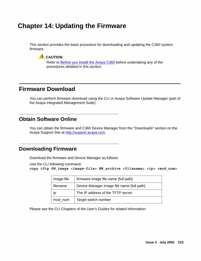
Issue 2 July 2005 223
Chapter 14: Updating the Firmware
This section provides the basic procedure for downloading and updating the C360 system firmware.
! CAUTION:CAUTION: Refer to Before you Install the Avaya C360 before undertaking any of the
procedures detailed in this section.
Firmware DownloadYou can perform firmware download using the CLI or Avaya Software Update Manager (part of the Avaya Integrated Management Suite).
Obtain Software OnlineYou can obtain the firmware and C360 Device Manager from the "Downloads" section on the Avaya Support Site at http://support.avaya.com.
Downloading FirmwareDownload the firmware and Device Manager as follows:
Use the CLI following command:copy tftp SW_image <image-file> EW_archive <filename> <ip> <mod_num>
Please see the CLI Chapters of the User's Guides for related information.
image-file firmware image file name (full path)
filename Device Manager image file name (full path)
ip The IP address of the TFTP server
mod_num Target switch number
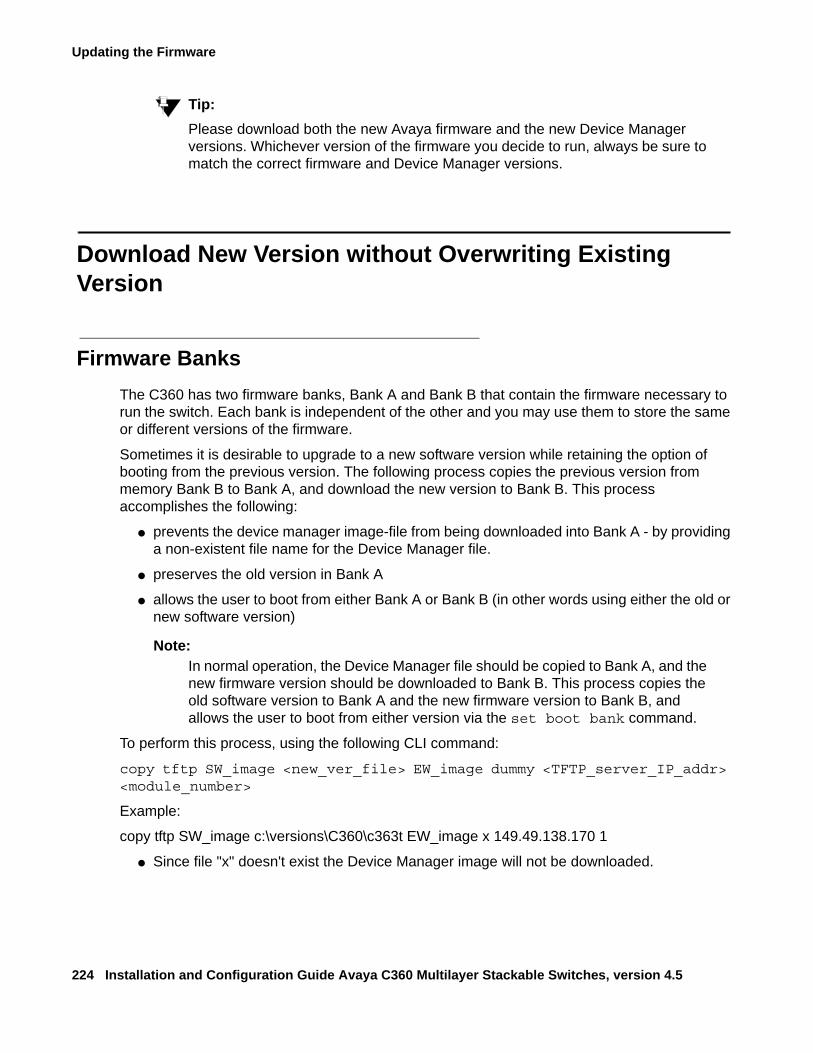
Updating the Firmware
224 Installation and Configuration Guide Avaya C360 Multilayer Stackable Switches, version 4.5
Tip:Tip: Please download both the new Avaya firmware and the new Device Manager
versions. Whichever version of the firmware you decide to run, always be sure to match the correct firmware and Device Manager versions.
Download New Version without Overwriting Existing Version
Firmware BanksThe C360 has two firmware banks, Bank A and Bank B that contain the firmware necessary to run the switch. Each bank is independent of the other and you may use them to store the same or different versions of the firmware.
Sometimes it is desirable to upgrade to a new software version while retaining the option of booting from the previous version. The following process copies the previous version from memory Bank B to Bank A, and download the new version to Bank B. This process accomplishes the following:
● prevents the device manager image-file from being downloaded into Bank A - by providing a non-existent file name for the Device Manager file.
● preserves the old version in Bank A
● allows the user to boot from either Bank A or Bank B (in other words using either the old or new software version)
Note:Note: In normal operation, the Device Manager file should be copied to Bank A, and the
new firmware version should be downloaded to Bank B. This process copies the old software version to Bank A and the new firmware version to Bank B, and allows the user to boot from either version via the set boot bank command.
To perform this process, using the following CLI command:
copy tftp SW_image <new_ver_file> EW_image dummy <TFTP_server_IP_addr> <module_number>
Example:
copy tftp SW_image c:\versions\C360\c363t EW_image x 149.49.138.170 1
● Since file "x" doesn't exist the Device Manager image will not be downloaded.
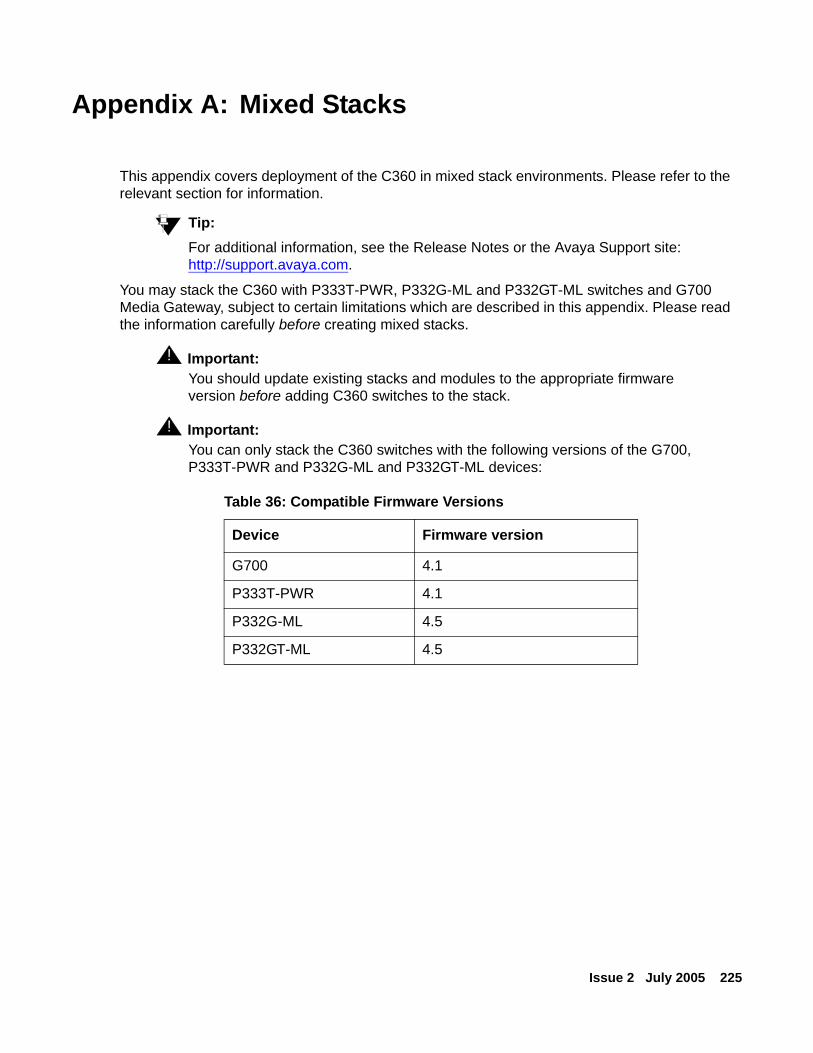
Issue 2 July 2005 225
Appendix A: Mixed Stacks
This appendix covers deployment of the C360 in mixed stack environments. Please refer to the relevant section for information.
Tip:Tip: For additional information, see the Release Notes or the Avaya Support site:
http://support.avaya.com.
You may stack the C360 with P333T-PWR, P332G-ML and P332GT-ML switches and G700 Media Gateway, subject to certain limitations which are described in this appendix. Please read the information carefully before creating mixed stacks.
! Important:Important: You should update existing stacks and modules to the appropriate firmware
version before adding C360 switches to the stack.
! Important:Important: You can only stack the C360 switches with the following versions of the G700,
P333T-PWR and P332G-ML and P332GT-ML devices:
Table 36: Compatible Firmware Versions
Device Firmware version
G700 4.1
P333T-PWR 4.1
P332G-ML 4.5
P332GT-ML 4.5
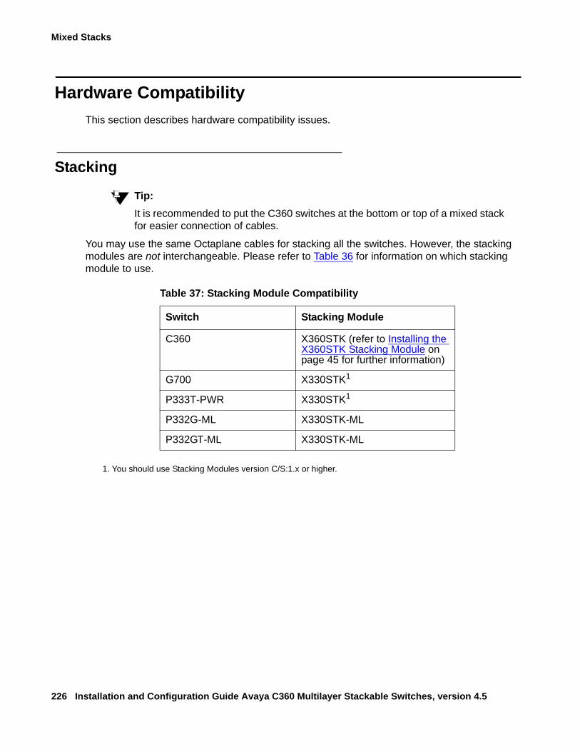
Mixed Stacks
226 Installation and Configuration Guide Avaya C360 Multilayer Stackable Switches, version 4.5
Hardware CompatibilityThis section describes hardware compatibility issues.
Stacking
Tip:Tip: It is recommended to put the C360 switches at the bottom or top of a mixed stack
for easier connection of cables.
You may use the same Octaplane cables for stacking all the switches. However, the stacking modules are not interchangeable. Please refer to Table 36 for information on which stacking module to use.
1. You should use Stacking Modules version C/S:1.x or higher.
Table 37: Stacking Module Compatibility
Switch Stacking Module
C360 X360STK (refer to Installing the X360STK Stacking Module on page 45 for further information)
G700 X330STK1
P333T-PWR X330STK1
P332G-ML X330STK-ML
P332GT-ML X330STK-ML
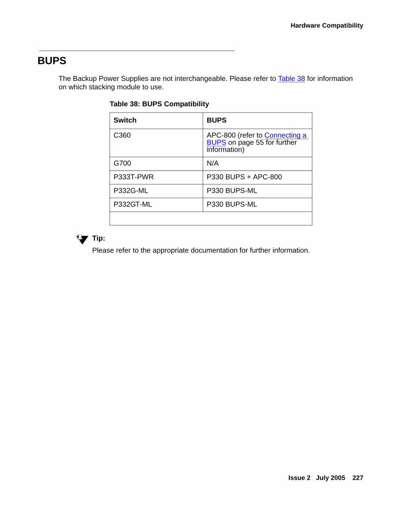
Hardware Compatibility
Issue 2 July 2005 227
BUPSThe Backup Power Supplies are not interchangeable. Please refer to Table 38 for information on which stacking module to use.
Tip:Tip: Please refer to the appropriate documentation for further information.
Table 38: BUPS Compatibility
Switch BUPS
C360 APC-800 (refer to Connecting a BUPS on page 55 for further information)
G700 N/A
P333T-PWR P330 BUPS + APC-800
P332G-ML P330 BUPS-ML
P332GT-ML P330 BUPS-ML
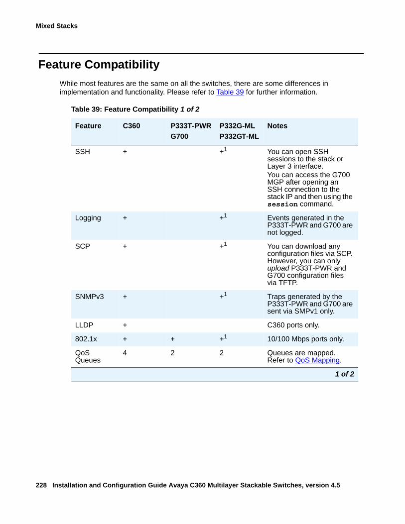
Mixed Stacks
228 Installation and Configuration Guide Avaya C360 Multilayer Stackable Switches, version 4.5
Feature CompatibilityWhile most features are the same on all the switches, there are some differences in implementation and functionality. Please refer to Table 39 for further information.
Table 39: Feature Compatibility 1 of 2
Feature C360 P333T-PWRG700
P332G-MLP332GT-ML
Notes
SSH + +1 You can open SSH sessions to the stack or Layer 3 interface.You can access the G700 MGP after opening an SSH connection to the stack IP and then using the session command.
Logging + +1 Events generated in the P333T-PWR and G700 are not logged.
SCP + +1 You can download any configuration files via SCP. However, you can only upload P333T-PWR and G700 configuration files via TFTP.
SNMPv3 + +1 Traps generated by the P333T-PWR and G700 are sent via SMPv1 only.
LLDP + C360 ports only.
802.1x + + +1 10/100 Mbps ports only.
QoS Queues
4 2 2 Queues are mapped. Refer to QoS Mapping.
1 of 2
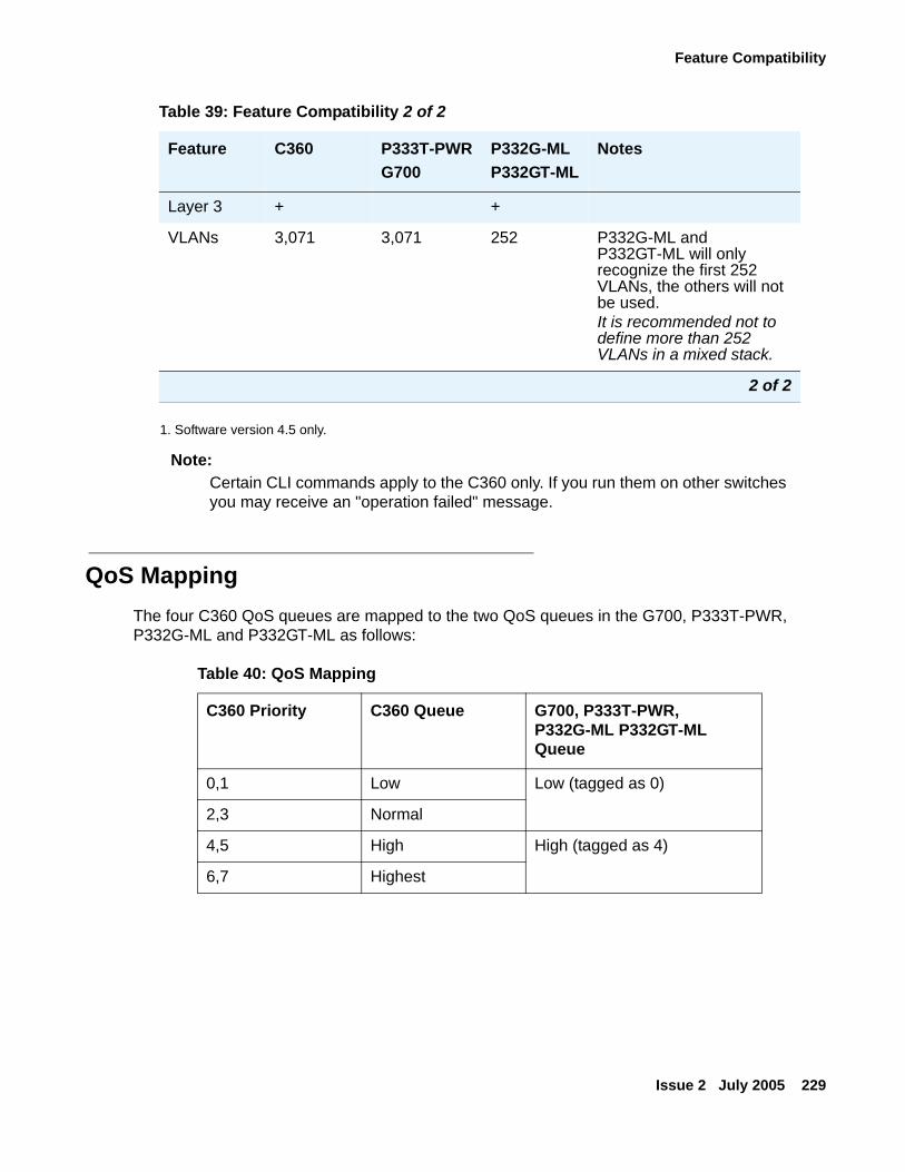
Feature Compatibility
Issue 2 July 2005 229
1. Software version 4.5 only.
Note:Note: Certain CLI commands apply to the C360 only. If you run them on other switches
you may receive an "operation failed" message.
QoS MappingThe four C360 QoS queues are mapped to the two QoS queues in the G700, P333T-PWR, P332G-ML and P332GT-ML as follows:
Layer 3 + +
VLANs 3,071 3,071 252 P332G-ML and P332GT-ML will only recognize the first 252 VLANs, the others will not be used. It is recommended not to define more than 252 VLANs in a mixed stack.
Table 39: Feature Compatibility 2 of 2
Feature C360 P333T-PWRG700
P332G-MLP332GT-ML
Notes
2 of 2
Table 40: QoS Mapping
C360 Priority C360 Queue G700, P333T-PWR, P332G-ML P332GT-ML Queue
0,1 Low Low (tagged as 0)
2,3 Normal
4,5 High High (tagged as 4)
6,7 Highest

Mixed Stacks
230 Installation and Configuration Guide Avaya C360 Multilayer Stackable Switches, version 4.5
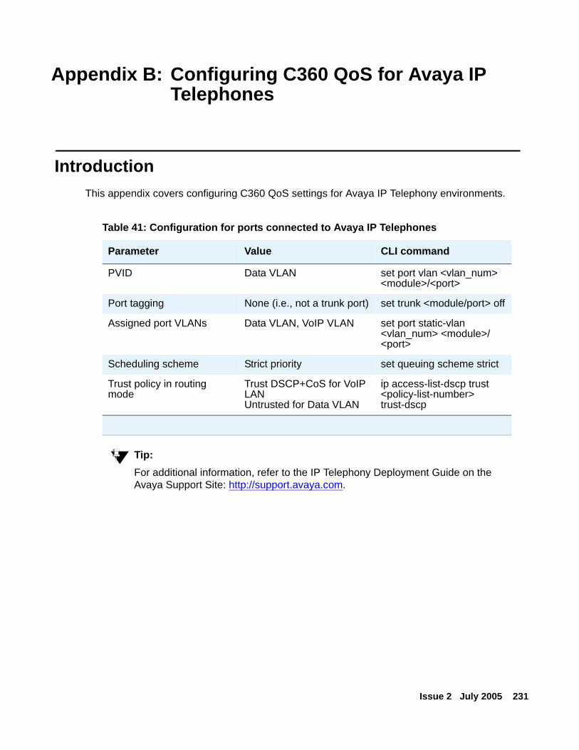
Issue 2 July 2005 231
Appendix B: Configuring C360 QoS for Avaya IP Telephones
IntroductionThis appendix covers configuring C360 QoS settings for Avaya IP Telephony environments.
Tip:Tip: For additional information, refer to the IP Telephony Deployment Guide on the
Avaya Support Site: http://support.avaya.com.
Table 41: Configuration for ports connected to Avaya IP Telephones
Parameter Value CLI command
PVID Data VLAN set port vlan <vlan_num> <module>/<port>
Port tagging None (i.e., not a trunk port) set trunk <module/port> off
Assigned port VLANs Data VLAN, VoIP VLAN set port static-vlan <vlan_num> <module>/<port>
Scheduling scheme Strict priority set queuing scheme strict
Trust policy in routing mode
Trust DSCP+CoS for VoIP LANUntrusted for Data VLAN
ip access-list-dscp trust <policy-list-number> trust-dscp

Configuring C360 QoS for Avaya IP Telephones
232 Installation and Configuration Guide Avaya C360 Multilayer Stackable Switches, version 4.5
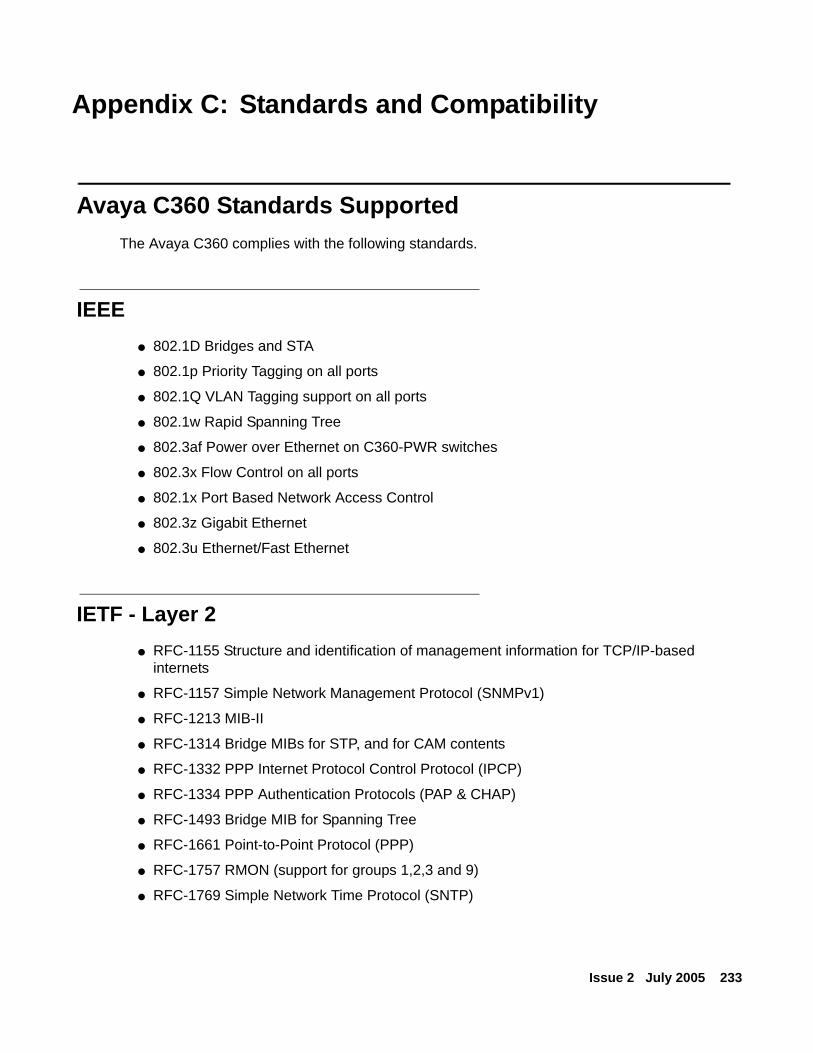
Issue 2 July 2005 233
Appendix C: Standards and Compatibility
Avaya C360 Standards SupportedThe Avaya C360 complies with the following standards.
IEEE● 802.1D Bridges and STA
● 802.1p Priority Tagging on all ports
● 802.1Q VLAN Tagging support on all ports
● 802.1w Rapid Spanning Tree
● 802.3af Power over Ethernet on C360-PWR switches
● 802.3x Flow Control on all ports
● 802.1x Port Based Network Access Control
● 802.3z Gigabit Ethernet
● 802.3u Ethernet/Fast Ethernet
IETF - Layer 2● RFC-1155 Structure and identification of management information for TCP/IP-based
internets
● RFC-1157 Simple Network Management Protocol (SNMPv1)
● RFC-1213 MIB-II
● RFC-1314 Bridge MIBs for STP, and for CAM contents
● RFC-1332 PPP Internet Protocol Control Protocol (IPCP)
● RFC-1334 PPP Authentication Protocols (PAP & CHAP)
● RFC-1493 Bridge MIB for Spanning Tree
● RFC-1661 Point-to-Point Protocol (PPP)
● RFC-1757 RMON (support for groups 1,2,3 and 9)
● RFC-1769 Simple Network Time Protocol (SNTP)
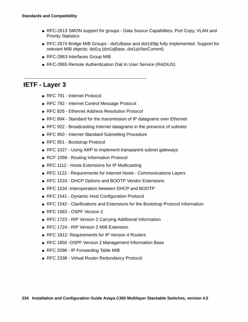
Standards and Compatibility
234 Installation and Configuration Guide Avaya C360 Multilayer Stackable Switches, version 4.5
● RFC-2613 SMON support for groups - Data Source Capabilities, Port Copy, VLAN and Priority Statistics
● RFC-2674 Bridge MIB Groups - dot1dbase and dot1dStp fully implemented. Support for relevant MIB objects: dot1q (dot1qBase, dot1qVlanCurrent)
● RFC-2863 Interfaces Group MIB
● RFC-2865 Remote Authentication Dial In User Service (RADIUS)
IETF - Layer 3● RFC 791 - Internet Protocol
● RFC 792 - Internet Control Message Protocol
● RFC 826 - Ethernet Address Resolution Protocol
● RFC 894 - Standard for the transmission of IP datagrams over Ethernet
● RFC 922 - Broadcasting Internet datagrams in the presence of subnets
● RFC 950 - Internet Standard Subnetting Procedure
● RFC 951 - Bootstrap Protocol
● RFC 1027 - Using ARP to implement transparent subnet gateways
● RCF 1058 - Routing Information Protocol
● RFC 1112 - Hosts Extensions for IP Multicasting
● RFC 1122 - Requirements for Internet Hosts - Communications Layers
● RFC 1533 - DHCP Options and BOOTP Vendor Extensions
● RFC 1534 -Interoperation between DHCP and BOOTP
● RFC 1541 - Dynamic Host Configuration Protocol
● RFC 1542 - Clarifications and Extensions for the Bootstrap Protocol Information
● RFC 1583 - OSPF Version 2
● RFC 1723 - RIP Version 2 Carrying Additional Information
● RFC 1724 - RIP Version 2 MIB Extension
● RFC 1812- Requirements for IP Version 4 Routers
● RFC 1850 -OSPF Version 2 Management Information Base
● RFC 2096 - IP Forwarding Table MIB
● RFC 2338 - Virtual Router Redundancy Protocol
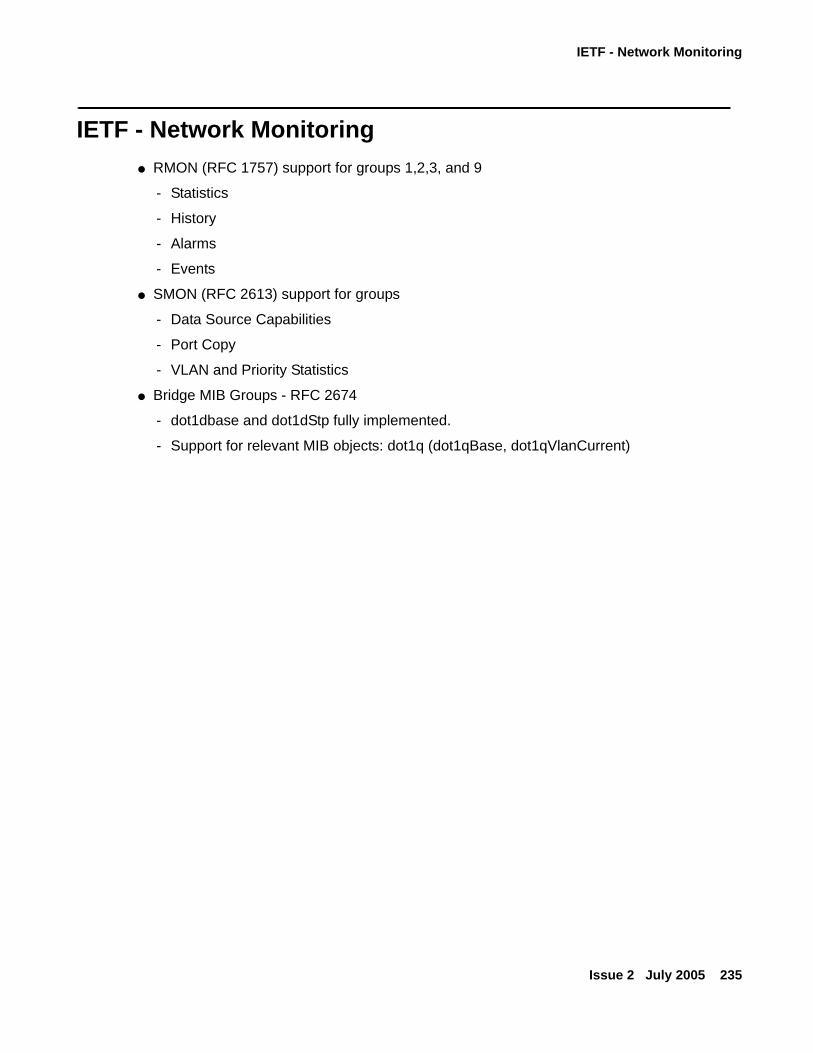
IETF - Network Monitoring
Issue 2 July 2005 235
IETF - Network Monitoring● RMON (RFC 1757) support for groups 1,2,3, and 9
- Statistics
- History
- Alarms
- Events
● SMON (RFC 2613) support for groups
- Data Source Capabilities
- Port Copy
- VLAN and Priority Statistics
● Bridge MIB Groups - RFC 2674
- dot1dbase and dot1dStp fully implemented.
- Support for relevant MIB objects: dot1q (dot1qBase, dot1qVlanCurrent)

Standards and Compatibility
236 Installation and Configuration Guide Avaya C360 Multilayer Stackable Switches, version 4.5
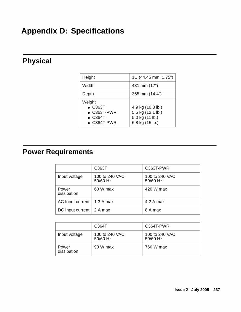
Issue 2 July 2005 237
Appendix D: Specifications
Physical
Power Requirements
Height 1U (44.45 mm, 1.75”)
Width 431 mm (17”)
Depth 365 mm (14.4”)
Weight● C363T● C363T-PWR● C364T● C364T-PWR
4.9 kg (10.8 lb.)5.5 kg (12.1 lb.)5.0 kg (11 lb.)6.8 kg (15 lb.)
C363T C363T-PWR
Input voltage 100 to 240 VAC50/60 Hz
100 to 240 VAC50/60 Hz
Power dissipation
60 W max 420 W max
AC Input current 1.3 A max 4.2 A max
DC Input current 2 A max 8 A max
C364T C364T-PWR
Input voltage 100 to 240 VAC50/60 Hz
100 to 240 VAC50/60 Hz
Power dissipation
90 W max 760 W max
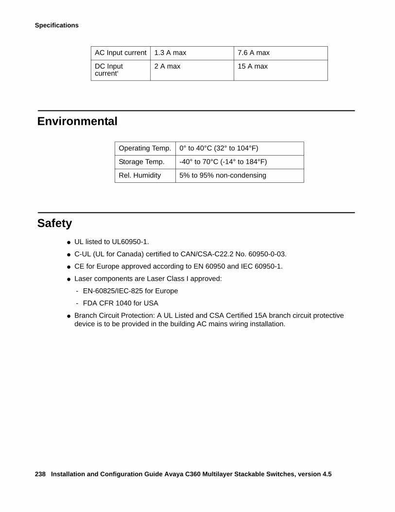
Specifications
238 Installation and Configuration Guide Avaya C360 Multilayer Stackable Switches, version 4.5
Environmental
Safety● UL listed to UL60950-1.
● C-UL (UL for Canada) certified to CAN/CSA-C22.2 No. 60950-0-03.
● CE for Europe approved according to EN 60950 and IEC 60950-1.
● Laser components are Laser Class I approved:
- EN-60825/IEC-825 for Europe
- FDA CFR 1040 for USA
● Branch Circuit Protection: A UL Listed and CSA Certified 15A branch circuit protective device is to be provided in the building AC mains wiring installation.
AC Input current 1.3 A max 7.6 A max
DC Input current‘
2 A max 15 A max
Operating Temp. 0° to 40°C (32° to 104°F)
Storage Temp. -40° to 70°C (-14° to 184°F)
Rel. Humidity 5% to 95% non-condensing
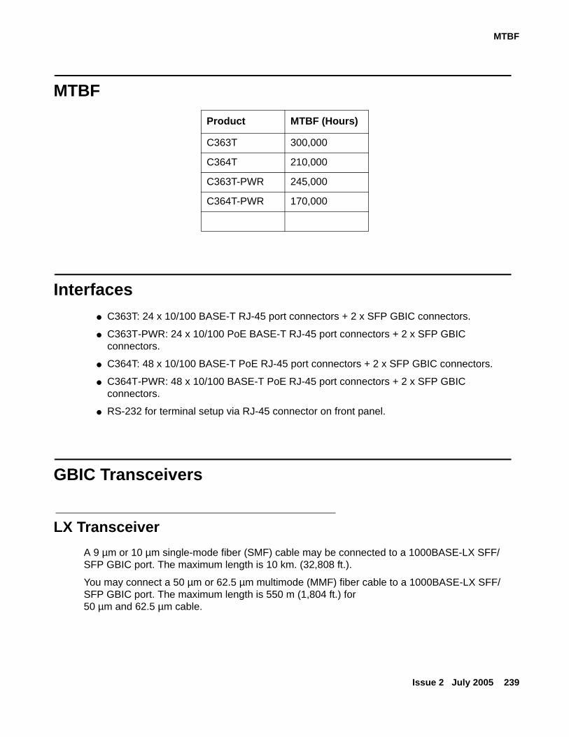
MTBF
Issue 2 July 2005 239
MTBF
Interfaces● C363T: 24 x 10/100 BASE-T RJ-45 port connectors + 2 x SFP GBIC connectors.
● C363T-PWR: 24 x 10/100 PoE BASE-T RJ-45 port connectors + 2 x SFP GBIC connectors.
● C364T: 48 x 10/100 BASE-T PoE RJ-45 port connectors + 2 x SFP GBIC connectors.
● C364T-PWR: 48 x 10/100 BASE-T PoE RJ-45 port connectors + 2 x SFP GBIC connectors.
● RS-232 for terminal setup via RJ-45 connector on front panel.
GBIC Transceivers
LX TransceiverA 9 µm or 10 µm single-mode fiber (SMF) cable may be connected to a 1000BASE-LX SFF/SFP GBIC port. The maximum length is 10 km. (32,808 ft.).
You may connect a 50 µm or 62.5 µm multimode (MMF) fiber cable to a 1000BASE-LX SFF/SFP GBIC port. The maximum length is 550 m (1,804 ft.) for 50 µm and 62.5 µm cable.
Product MTBF (Hours)
C363T 300,000
C364T 210,000
C363T-PWR 245,000
C364T-PWR 170,000

Specifications
240 Installation and Configuration Guide Avaya C360 Multilayer Stackable Switches, version 4.5
The LX transceiver has a Wavelength of 1300 nm, Transmission Rate of 1.25 Gbps, Input Voltage of 3.3V, and Maximum Output Wattage of -2 dBm.
SX TransceiverYou may connect a 50 µm or 62.5 µm multimode (MMF) fiber cable to a 1000Base-SX SFF/SFP GBIC port. The maximum length is 500 m (1,640 ft.) for 50 µm and 220 m (722 ft.) for 62.5 µm cable.
The SX transceiver has a Wavelength of 850 nm, Transmission Rate of 1.25 Gbps, Input Voltage of 3.3V, and Maximum Output Wattage of -4 dBm.
ELX TransceiverYou may connect a 9 mm or 10 mm single-mode fiber (SMF) cable to a 1000BASE-ELX SFP GBIC port. The fiber length should be between a minimum length of 10 km (32,808) and a maximum length of 70 km (229,656 ft.). The fiber attenuation must be less than 0.3 dB/km for 70 km of fiber length.
The ELX transceiver has a Wavelength of 1550 nm, Transmission Rate of 1.25 Gbps, Input Power of 3.3V, and Maximum Output Optical Power of +5 dBm.
Copper TransceiverA 4-pair (8-wire) category 5 Ethernet cable terminated with an RJ-45 connector may be connected to a 1000BASE-T SFP GBIC port. The cable length can be a maximum of 100 m (328 ft.).
Tip:Tip: The copper ports operate at 1000 Mbps full-duplex only.
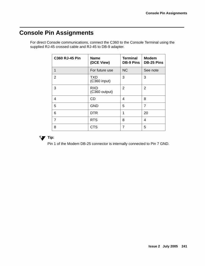
Console Pin Assignments
Issue 2 July 2005 241
Console Pin AssignmentsFor direct Console communications, connect the C360 to the Console Terminal using the supplied RJ-45 crossed cable and RJ-45 to DB-9 adapter.
Tip:Tip: Pin 1 of the Modem DB-25 connector is internally connected to Pin 7 GND.
C360 RJ-45 Pin Name(DCE View)
TerminalDB-9 Pins
ModemDB-25 Pins
1 For future use NC See note
2 TXD(C360 input)
3 3
3 RXD(C360 output)
2 2
4 CD 4 8
5 GND 5 7
6 DTR 1 20
7 RTS 8 4
8 CTS 7 5
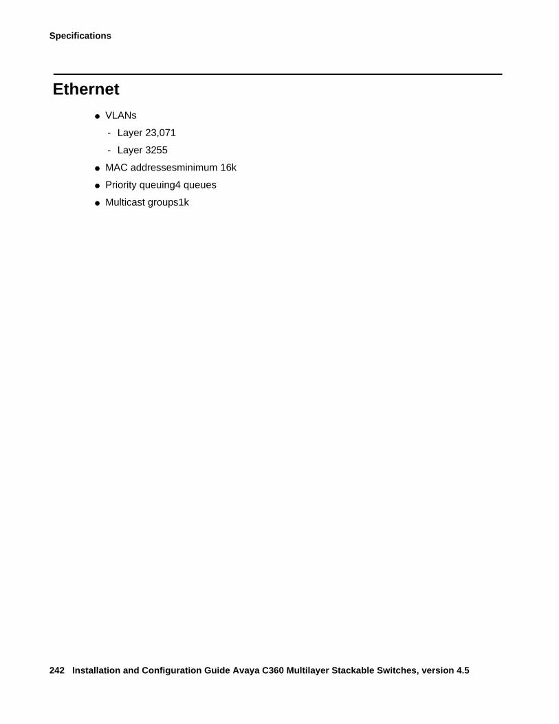
Specifications
242 Installation and Configuration Guide Avaya C360 Multilayer Stackable Switches, version 4.5
Ethernet● VLANs
- Layer 23,071
- Layer 3255
● MAC addressesminimum 16k
● Priority queuing4 queues
● Multicast groups1k
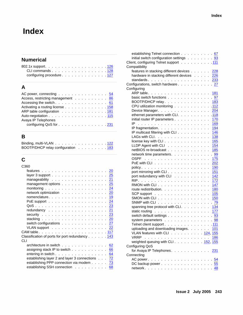
Issue 2 July 2005 243
Index
Index
Numerical802.1x support. . . . . . . . . . . . . . . . . . . 126
CLI commands . . . . . . . . . . . . . . . . . 128configuring procedure . . . . . . . . . . . . . . 127
AAC power, connecting . . . . . . . . . . . . . . . 54Access, restricting management . . . . . . . . . . 86Accessing the switch . . . . . . . . . . . . . . . . 61Activating a routing license . . . . . . . . . . . . . 158ARP table configuration . . . . . . . . . . . . . . 181Auto-negotiation . . . . . . . . . . . . . . . . . . 115Avaya IP Telephones
configuring QoS for . . . . . . . . . . . . . . . 231
BBinding, multi-VLAN . . . . . . . . . . . . . . . . 122BOOTP/DHCP relay configuration . . . . . . . . . 183
CC360
features . . . . . . . . . . . . . . . . . . . . 20layer 3 support . . . . . . . . . . . . . . . . . 25manageability . . . . . . . . . . . . . . . . . 21management options . . . . . . . . . . . . . . 25monitoring . . . . . . . . . . . . . . . . . . . 24network optimization . . . . . . . . . . . . . . 20nomenclature. . . . . . . . . . . . . . . . . . 19PoE support . . . . . . . . . . . . . . . . . . 24QoS . . . . . . . . . . . . . . . . . . . . . . 23redundancy . . . . . . . . . . . . . . . . . . 21security . . . . . . . . . . . . . . . . . . . . 23stacking . . . . . . . . . . . . . . . . . . . . 20switch configurations . . . . . . . . . . . . . . 27VLAN support . . . . . . . . . . . . . . . . . 22
CAM table . . . . . . . . . . . . . . . . . . . . . 117Classification of ports for port redundancy . . . . . . 143CLI
architecture in switch . . . . . . . . . . . . . . 62assigning stack IP to switch . . . . . . . . . . . 66entering in switch . . . . . . . . . . . . . . . . 64establishing layer 2 and layer 3 connections . . . 72establishing PPP connection via modem . . . . . 73establishing SSH connection . . . . . . . . . . 68
establishing Telnet connection . . . . . . . . . . 67initial switch configuration settings . . . . . . . . 93
Client, configuring Telnet support . . . . . . . . . . 111Compatibility
features in stacking different devices . . . . . . 228hardware in stacking different devices . . . . . 226standards . . . . . . . . . . . . . . . . . . . 233
Configurations, switch hardware . . . . . . . . . . . 27Configuring
ARP table. . . . . . . . . . . . . . . . . . . 181basic switch functions . . . . . . . . . . . . . . 97BOOTP/DHCP relay . . . . . . . . . . . . . . 183CPU utilization monitoring . . . . . . . . . . . .112Device Manager. . . . . . . . . . . . . . . . 204ethernet parameters with CLI. . . . . . . . . . .118initial router IP parameters . . . . . . . . . . . 170IP . . . . . . . . . . . . . . . . . . . . . . 169IP fragmentation. . . . . . . . . . . . . . . . 194IP multicast filtering with CLI . . . . . . . . . . 146LAGs with CLI. . . . . . . . . . . . . . . . . 138license key with CLI . . . . . . . . . . . . . . 165LLDP Agent with CLI . . . . . . . . . . . . . 154netBIOS re-broadcast . . . . . . . . . . . . . 185network time parameters. . . . . . . . . . . . . 99OSPF . . . . . . . . . . . . . . . . . . . . 175PoE with CLI . . . . . . . . . . . . . . . . . 202policy . . . . . . . . . . . . . . . . . . . . . 190port mirroring with CLI . . . . . . . . . . . . . 151port redundancy with CLI . . . . . . . . . . . 142RIP. . . . . . . . . . . . . . . . . . . . . . 172RMON with CLI . . . . . . . . . . . . . . . . 147route redistribution. . . . . . . . . . . . . . . 180SCP support . . . . . . . . . . . . . . . . . 105SMON with CLI . . . . . . . . . . . . . . . . 150SNMP with CLI . . . . . . . . . . . . . . . . . 79spanning tree protocol with CLI. . . . . . . . . 134static routing . . . . . . . . . . . . . . . . . 177switch default settings . . . . . . . . . . . . . . 93system parameters . . . . . . . . . . . . . . . 98Telnet client support . . . . . . . . . . . . . . . 111uploading and downloading images. . . . . . . 101VLAN features with CLI . . . . . . . . . . 124, 155VRRP . . . . . . . . . . . . . . . . . . . . 186weighted queuing with CLI . . . . . . . . . 152, 155
Configuring QoSfor Avaya IP Telephones. . . . . . . . . . . . 231
ConnectingAC power . . . . . . . . . . . . . . . . . . . . 54DC backup power . . . . . . . . . . . . . . . . 55network . . . . . . . . . . . . . . . . . . . . . 48
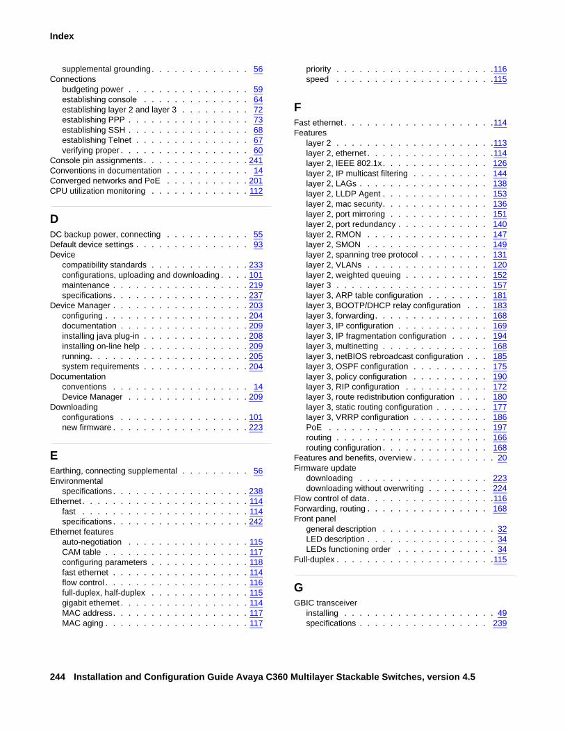
244 Installation and Configuration Guide Avaya C360 Multilayer Stackable Switches, version 4.5
Index
supplemental grounding. . . . . . . . . . . . . 56Connections
budgeting power . . . . . . . . . . . . . . . . 59establishing console . . . . . . . . . . . . . . 64establishing layer 2 and layer 3 . . . . . . . . . 72establishing PPP . . . . . . . . . . . . . . . . 73establishing SSH . . . . . . . . . . . . . . . . 68establishing Telnet . . . . . . . . . . . . . . . 67verifying proper . . . . . . . . . . . . . . . . . 60
Console pin assignments . . . . . . . . . . . . . . 241Conventions in documentation . . . . . . . . . . . 14Converged networks and PoE . . . . . . . . . . . 201CPU utilization monitoring . . . . . . . . . . . . . 112
DDC backup power, connecting . . . . . . . . . . . 55Default device settings . . . . . . . . . . . . . . . 93Device
compatibility standards . . . . . . . . . . . . . 233configurations, uploading and downloading . . . . 101maintenance . . . . . . . . . . . . . . . . . . 219specifications . . . . . . . . . . . . . . . . . . 237
Device Manager . . . . . . . . . . . . . . . . . . 203configuring . . . . . . . . . . . . . . . . . . . 204documentation . . . . . . . . . . . . . . . . . 209installing java plug-in . . . . . . . . . . . . . . 208installing on-line help . . . . . . . . . . . . . . 209running. . . . . . . . . . . . . . . . . . . . . 205system requirements . . . . . . . . . . . . . . 204
Documentationconventions . . . . . . . . . . . . . . . . . . 14Device Manager . . . . . . . . . . . . . . . . 209
Downloadingconfigurations . . . . . . . . . . . . . . . . . 101new firmware . . . . . . . . . . . . . . . . . . 223
EEarthing, connecting supplemental . . . . . . . . . 56Environmental
specifications . . . . . . . . . . . . . . . . . . 238Ethernet . . . . . . . . . . . . . . . . . . . . . . 114
fast . . . . . . . . . . . . . . . . . . . . . . 114specifications . . . . . . . . . . . . . . . . . . 242
Ethernet featuresauto-negotiation . . . . . . . . . . . . . . . . 115CAM table . . . . . . . . . . . . . . . . . . . 117configuring parameters . . . . . . . . . . . . . 118fast ethernet . . . . . . . . . . . . . . . . . . 114flow control . . . . . . . . . . . . . . . . . . . 116full-duplex, half-duplex . . . . . . . . . . . . . 115gigabit ethernet . . . . . . . . . . . . . . . . . 114MAC address. . . . . . . . . . . . . . . . . . 117MAC aging . . . . . . . . . . . . . . . . . . . 117
priority . . . . . . . . . . . . . . . . . . . . .116speed . . . . . . . . . . . . . . . . . . . . .115
FFast ethernet . . . . . . . . . . . . . . . . . . . .114Features
layer 2 . . . . . . . . . . . . . . . . . . . . .113layer 2, ethernet . . . . . . . . . . . . . . . . .114layer 2, IEEE 802.1x. . . . . . . . . . . . . . 126layer 2, IP multicast filtering . . . . . . . . . . 144layer 2, LAGs . . . . . . . . . . . . . . . . . 138layer 2, LLDP Agent . . . . . . . . . . . . . . 153layer 2, mac security. . . . . . . . . . . . . . 136layer 2, port mirroring . . . . . . . . . . . . . 151layer 2, port redundancy . . . . . . . . . . . . 140layer 2, RMON . . . . . . . . . . . . . . . . 147layer 2, SMON . . . . . . . . . . . . . . . . 149layer 2, spanning tree protocol . . . . . . . . . 131layer 2, VLANs . . . . . . . . . . . . . . . . 120layer 2, weighted queuing . . . . . . . . . . . 152layer 3 . . . . . . . . . . . . . . . . . . . . 157layer 3, ARP table configuration . . . . . . . . 181layer 3, BOOTP/DHCP relay configuration . . . 183layer 3, forwarding. . . . . . . . . . . . . . . 168layer 3, IP configuration . . . . . . . . . . . . 169layer 3, IP fragmentation configuration . . . . . 194layer 3, multinetting . . . . . . . . . . . . . . 168layer 3, netBIOS rebroadcast configuration . . . 185layer 3, OSPF configuration . . . . . . . . . . 175layer 3, policy configuration . . . . . . . . . . 190layer 3, RIP configuration . . . . . . . . . . . 172layer 3, route redistribution configuration . . . . 180layer 3, static routing configuration . . . . . . . 177layer 3, VRRP configuration . . . . . . . . . . 186PoE . . . . . . . . . . . . . . . . . . . . . 197routing . . . . . . . . . . . . . . . . . . . . 166routing configuration . . . . . . . . . . . . . . 168
Features and benefits, overview . . . . . . . . . . . 20Firmware update
downloading . . . . . . . . . . . . . . . . . 223downloading without overwriting . . . . . . . . 224
Flow control of data. . . . . . . . . . . . . . . . .116Forwarding, routing . . . . . . . . . . . . . . . . 168Front panel
general description . . . . . . . . . . . . . . . 32LED description . . . . . . . . . . . . . . . . . 34LEDs functioning order . . . . . . . . . . . . . 34
Full-duplex . . . . . . . . . . . . . . . . . . . . .115
GGBIC transceiver
installing . . . . . . . . . . . . . . . . . . . . 49specifications . . . . . . . . . . . . . . . . . 239
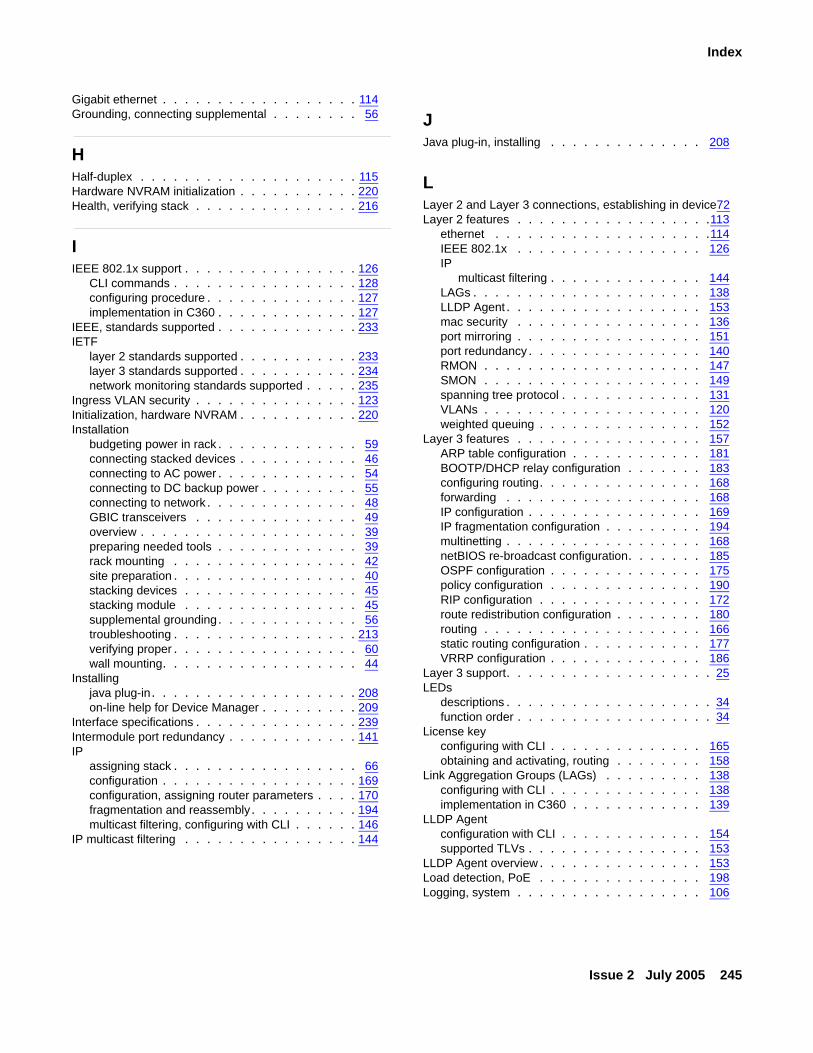
Issue 2 July 2005 245
Index
Gigabit ethernet . . . . . . . . . . . . . . . . . . 114Grounding, connecting supplemental . . . . . . . . 56
HHalf-duplex . . . . . . . . . . . . . . . . . . . . 115Hardware NVRAM initialization . . . . . . . . . . . 220Health, verifying stack . . . . . . . . . . . . . . . 216
IIEEE 802.1x support . . . . . . . . . . . . . . . . 126
CLI commands . . . . . . . . . . . . . . . . . 128configuring procedure . . . . . . . . . . . . . . 127implementation in C360 . . . . . . . . . . . . . 127
IEEE, standards supported . . . . . . . . . . . . . 233IETF
layer 2 standards supported . . . . . . . . . . . 233layer 3 standards supported . . . . . . . . . . . 234network monitoring standards supported . . . . . 235
Ingress VLAN security . . . . . . . . . . . . . . . 123Initialization, hardware NVRAM . . . . . . . . . . . 220Installation
budgeting power in rack . . . . . . . . . . . . . 59connecting stacked devices . . . . . . . . . . . 46connecting to AC power . . . . . . . . . . . . . 54connecting to DC backup power . . . . . . . . . 55connecting to network. . . . . . . . . . . . . . 48GBIC transceivers . . . . . . . . . . . . . . . 49overview . . . . . . . . . . . . . . . . . . . . 39preparing needed tools . . . . . . . . . . . . . 39rack mounting . . . . . . . . . . . . . . . . . 42site preparation . . . . . . . . . . . . . . . . . 40stacking devices . . . . . . . . . . . . . . . . 45stacking module . . . . . . . . . . . . . . . . 45supplemental grounding. . . . . . . . . . . . . 56troubleshooting . . . . . . . . . . . . . . . . . 213verifying proper . . . . . . . . . . . . . . . . . 60wall mounting. . . . . . . . . . . . . . . . . . 44
Installingjava plug-in. . . . . . . . . . . . . . . . . . . 208on-line help for Device Manager . . . . . . . . . 209
Interface specifications . . . . . . . . . . . . . . . 239Intermodule port redundancy . . . . . . . . . . . . 141IP
assigning stack . . . . . . . . . . . . . . . . . 66configuration . . . . . . . . . . . . . . . . . . 169configuration, assigning router parameters . . . . 170fragmentation and reassembly. . . . . . . . . . 194multicast filtering, configuring with CLI . . . . . . 146
IP multicast filtering . . . . . . . . . . . . . . . . 144
JJava plug-in, installing . . . . . . . . . . . . . . 208
LLayer 2 and Layer 3 connections, establishing in device72Layer 2 features . . . . . . . . . . . . . . . . . .113
ethernet . . . . . . . . . . . . . . . . . . . .114IEEE 802.1x . . . . . . . . . . . . . . . . . 126IP
multicast filtering . . . . . . . . . . . . . . 144LAGs . . . . . . . . . . . . . . . . . . . . . 138LLDP Agent . . . . . . . . . . . . . . . . . . 153mac security . . . . . . . . . . . . . . . . . 136port mirroring . . . . . . . . . . . . . . . . . 151port redundancy . . . . . . . . . . . . . . . . 140RMON . . . . . . . . . . . . . . . . . . . . 147SMON . . . . . . . . . . . . . . . . . . . . 149spanning tree protocol . . . . . . . . . . . . . 131VLANs . . . . . . . . . . . . . . . . . . . . 120weighted queuing . . . . . . . . . . . . . . . 152
Layer 3 features . . . . . . . . . . . . . . . . . 157ARP table configuration . . . . . . . . . . . . 181BOOTP/DHCP relay configuration . . . . . . . 183configuring routing. . . . . . . . . . . . . . . 168forwarding . . . . . . . . . . . . . . . . . . 168IP configuration . . . . . . . . . . . . . . . . 169IP fragmentation configuration . . . . . . . . . 194multinetting . . . . . . . . . . . . . . . . . . 168netBIOS re-broadcast configuration. . . . . . . 185OSPF configuration . . . . . . . . . . . . . . 175policy configuration . . . . . . . . . . . . . . 190RIP configuration . . . . . . . . . . . . . . . 172route redistribution configuration . . . . . . . . 180routing . . . . . . . . . . . . . . . . . . . . 166static routing configuration . . . . . . . . . . . 177VRRP configuration . . . . . . . . . . . . . . 186
Layer 3 support. . . . . . . . . . . . . . . . . . . 25LEDs
descriptions . . . . . . . . . . . . . . . . . . . 34function order . . . . . . . . . . . . . . . . . . 34
License keyconfiguring with CLI . . . . . . . . . . . . . . 165obtaining and activating, routing . . . . . . . . 158
Link Aggregation Groups (LAGs) . . . . . . . . . 138configuring with CLI . . . . . . . . . . . . . . 138implementation in C360 . . . . . . . . . . . . 139
LLDP Agentconfiguration with CLI . . . . . . . . . . . . . 154supported TLVs . . . . . . . . . . . . . . . . 153
LLDP Agent overview . . . . . . . . . . . . . . . 153Load detection, PoE . . . . . . . . . . . . . . . 198Logging, system . . . . . . . . . . . . . . . . . 106
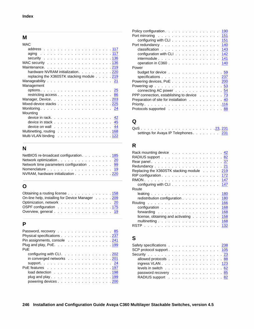
246 Installation and Configuration Guide Avaya C360 Multilayer Stackable Switches, version 4.5
Index
MMAC
address . . . . . . . . . . . . . . . . . . . . 117aging . . . . . . . . . . . . . . . . . . . . . 117security . . . . . . . . . . . . . . . . . . . . 136
MAC security . . . . . . . . . . . . . . . . . . . 136Maintenance. . . . . . . . . . . . . . . . . . . . 219
hardware NVRAM initialization. . . . . . . . . . 220replacing the X360STK stacking module . . . . . 219
Manageability . . . . . . . . . . . . . . . . . . . 21Management
options . . . . . . . . . . . . . . . . . . . . . 25restricting access . . . . . . . . . . . . . . . . 86
Manager, Device. . . . . . . . . . . . . . . . . . 203Mixed-device stacks . . . . . . . . . . . . . . . . 225Monitoring . . . . . . . . . . . . . . . . . . . . . 24Mounting
device in rack. . . . . . . . . . . . . . . . . . 42device in stack . . . . . . . . . . . . . . . . . 45device on wall . . . . . . . . . . . . . . . . . 44
Multinetting, routing . . . . . . . . . . . . . . . . 168Multi-VLAN binding . . . . . . . . . . . . . . . . 122
NNetBIOS re-broadcast configuration. . . . . . . . . 185Network optimization . . . . . . . . . . . . . . . . 20Network time parameters configuration . . . . . . . 99Nomenclature . . . . . . . . . . . . . . . . . . . 19NVRAM, hardware initialization . . . . . . . . . . . 220
OObtaining a routing license . . . . . . . . . . . . . 158On-line help, installing for Device Manager . . . . . 209Optimization, network . . . . . . . . . . . . . . . 20OSPF configuration . . . . . . . . . . . . . . . . 175Overview, general . . . . . . . . . . . . . . . . . 19
PPassword, recovery . . . . . . . . . . . . . . . . 85Physical specifications . . . . . . . . . . . . . . . 237Pin assignments, console . . . . . . . . . . . . . 241Plug and play, PoE. . . . . . . . . . . . . . . . . 199PoE
configuring with CLI . . . . . . . . . . . . . . . 202in converged networks . . . . . . . . . . . . . 201support. . . . . . . . . . . . . . . . . . . . . 24
PoE features . . . . . . . . . . . . . . . . . . . 197load detection . . . . . . . . . . . . . . . . . 198plug and play . . . . . . . . . . . . . . . . . . 199powering devices . . . . . . . . . . . . . . . . 200
Policy configuration . . . . . . . . . . . . . . . . 190Port mirroring . . . . . . . . . . . . . . . . . . 151
configuring with CLI . . . . . . . . . . . . . . 151Port redundancy . . . . . . . . . . . . . . . . . 140
classification . . . . . . . . . . . . . . . . . 143configuration with CLI . . . . . . . . . . . . . 142intermodule . . . . . . . . . . . . . . . . . . 141operation in C360 . . . . . . . . . . . . . . . 140
Powerbudget for device . . . . . . . . . . . . . . . . 59specifications . . . . . . . . . . . . . . . . . 237
Powering devices, PoE . . . . . . . . . . . . . . 200Powering up . . . . . . . . . . . . . . . . . . . . 53
connecting AC power . . . . . . . . . . . . . . 54PPP connection, establishing to device . . . . . . . 73Preparation of site for installation . . . . . . . . . . 40Priority . . . . . . . . . . . . . . . . . . . . . . .116Protocols supported . . . . . . . . . . . . . . . . 88
QQoS . . . . . . . . . . . . . . . . . . . . . .23, 231
settings for Avaya IP Telephones. . . . . . . . 231
RRack mounting device . . . . . . . . . . . . . . . 42RADIUS support . . . . . . . . . . . . . . . . . . 82Rear panel . . . . . . . . . . . . . . . . . . . . . 37Redundancy . . . . . . . . . . . . . . . . . . . . 21Replacing the X360STK stacking module . . . . . 219RIP configuration . . . . . . . . . . . . . . . . . 172RMON . . . . . . . . . . . . . . . . . . . . . . 147
configuring with CLI . . . . . . . . . . . . . . 147Route
leaking . . . . . . . . . . . . . . . . . . . . 180redistribution configuration . . . . . . . . . . . 180
Routing . . . . . . . . . . . . . . . . . . . . . 166configuration . . . . . . . . . . . . . . . . . 168forwarding . . . . . . . . . . . . . . . . . . 168license, obtaining and activating . . . . . . . . 158multinetting . . . . . . . . . . . . . . . . . . 168
RSTP . . . . . . . . . . . . . . . . . . . . . . 132
SSafety specifications . . . . . . . . . . . . . . . 238SCP protocol support . . . . . . . . . . . . . . . 105Security . . . . . . . . . . . . . . . . . . . . . . 23
allowed protocols . . . . . . . . . . . . . . . . 88ingress VLAN . . . . . . . . . . . . . . . . . 123levels in switch . . . . . . . . . . . . . . . . . 62password recovery . . . . . . . . . . . . . . . 85RADIUS support . . . . . . . . . . . . . . . . 82
Issue 2 July 2005 247
Index
restricting management access . . . . . . . . . 86SCP support . . . . . . . . . . . . . . . . . . 105SNMP . . . . . . . . . . . . . . . . . . . . . 75
Settings, device default. . . . . . . . . . . . . . . 93Site preparation . . . . . . . . . . . . . . . . . . 40SMON . . . . . . . . . . . . . . . . . . . . . . 149
configuring with CLI . . . . . . . . . . . . . . . 150SNMP. . . . . . . . . . . . . . . . . . . . . . . 75
configuring with CLI . . . . . . . . . . . . . . . 79SNMPv1 . . . . . . . . . . . . . . . . . . . . 76SNMPv2c . . . . . . . . . . . . . . . . . . . 76SNMPv3 . . . . . . . . . . . . . . . . . . . . 77
Spanning Tree Protocol . . . . . . . . . . . . . . 131configuring with CLI . . . . . . . . . . . . . . . 134implementation in C360 . . . . . . . . . . . . . 133RSTP . . . . . . . . . . . . . . . . . . . . . 132
Specifications . . . . . . . . . . . . . . . . . . . 237console pin assignments . . . . . . . . . . . . 241environmental . . . . . . . . . . . . . . . . . 238ethernet . . . . . . . . . . . . . . . . . . . . 242GBIC transceivers . . . . . . . . . . . . . . . 239interfaces . . . . . . . . . . . . . . . . . . . 239physical . . . . . . . . . . . . . . . . . . . . 237power . . . . . . . . . . . . . . . . . . . . . 237safety . . . . . . . . . . . . . . . . . . . . . 238
Speeds of ethernet. . . . . . . . . . . . . . . . . 115SSH connection, establishing to device . . . . . . . 68Stack
health, verifying. . . . . . . . . . . . . . . . . 216IP, assigning to device . . . . . . . . . . . . . 66
Stacking. . . . . . . . . . . . . . . . . . . . . . 45connecting stacked devices . . . . . . . . . . . 46devices . . . . . . . . . . . . . . . . . . . . 45different devices, feature compatibility . . . . . . 228different devices, hardware compatibility . . . . . 226installing stacking module . . . . . . . . . . . . 45installing the X360STK stacking module . . . . . 45inter-connecting switches . . . . . . . . . . . . 46mixing Avaya devices . . . . . . . . . . . . . . 225replacing the X360STK stacking module . . . . . 219the C360 . . . . . . . . . . . . . . . . . . . . 20
Standards supported . . . . . . . . . . . . . . . . 233IEEE. . . . . . . . . . . . . . . . . . . . . . 233IETF layer 2 . . . . . . . . . . . . . . . . . . 233IETF layer 3 . . . . . . . . . . . . . . . . . . 234IETF network monitoring . . . . . . . . . . . . 235
Static routing configuration . . . . . . . . . . . . . 177Supported standards . . . . . . . . . . . . . . . . 233Switch
configuration, basic . . . . . . . . . . . . . . . 97hardware configurations. . . . . . . . . . . . . 27
Switch accessassigning stack IP . . . . . . . . . . . . . . . 66CLI architecture . . . . . . . . . . . . . . . . 62entering CLI . . . . . . . . . . . . . . . . . . 64
establishing console connection . . . . . . . . . 64establishing layer 2 and layer 3 connections. . . . 72establishing PPP connection via modem . . . . . 73establishing SSH connection . . . . . . . . . . . 68establishing Telnet connection . . . . . . . . . . 67overview . . . . . . . . . . . . . . . . . . . . 61security levels . . . . . . . . . . . . . . . . . . 62
Systemlogging . . . . . . . . . . . . . . . . . . . . 106parameters configuration. . . . . . . . . . . . . 98requirements, Device Manager . . . . . . . . . 204
TTagging, VLAN . . . . . . . . . . . . . . . . . . 121Telnet
client support, configuring . . . . . . . . . . . . 111connection, establishing to device . . . . . . . . 67
TLVs . . . . . . . . . . . . . . . . . . . . . . 153Transceiver
installing . . . . . . . . . . . . . . . . . . . . 49specifications, GBIC . . . . . . . . . . . . . . 239
Troubleshooting installation . . . . . . . . . . . . 213verifying stack integrity (health). . . . . . . . . 216
UUploading configurations . . . . . . . . . . . . . 101
VVLAN features
configuring with CLI . . . . . . . . . . . . 124, 155ingress security . . . . . . . . . . . . . . . . 123multi-VLAN binding . . . . . . . . . . . . . . 122tagging . . . . . . . . . . . . . . . . . . . . 121
VLAN support . . . . . . . . . . . . . . . . . . . 22VRRP configuration. . . . . . . . . . . . . . . . 186
WWall mounting device . . . . . . . . . . . . . . . . 44Weighted queuing . . . . . . . . . . . . . . . . 152
configuration with CLI . . . . . . . . . . . 152, 155implementation in C360 . . . . . . . . . . . . 152
XX360STK stacking module
installing . . . . . . . . . . . . . . . . . . . . 45replacing . . . . . . . . . . . . . . . . . . . 219

248 Installation and Configuration Guide Avaya C360 Multilayer Stackable Switches, version 4.5
Index


