Innovation Voice Mail PBX Installation and Testing Guide Avaya Control LAN (C-LAN) Integration using Dialogic Media Gateways 1841 Bourbon Road Cross Plains, Wisconsin 1-800-424-6757 www.innovationtw.com
Transcript
Innovation Voice Mail PBX Installation and Testing Guide
Avaya Control LAN (C-LAN) Integration using Dialogic Media Gateways
1841 Bourbon Road
Cross Plains, Wisconsin 1-800-424-6757
www.innovationtw.com
Innovation Voice Mail PBX Installation and Testing Guide 9/6/2011
1
Avaya C-LAN Integration using DMG (Dialogic Media Gateways) Requirements: ♦ Release 7 or higher** ♦ TN799 C-LAN circuit pack (used on older legacy systems or using a G650 media gateway to
support traditional circuit packs) Use of a TN799 circuit pack may also require the following: 259A Adapter (25pair male amp connector to RJ45 female connector) Network crossover cable, ASSY NO 846943306
♦ If your PBX is a S8300 (or other S8xxx type models), you may use “processor over ethernet” for the CLAN connection.
♦ An analog extension (configured as type “2500”) for each voicemail port ♦ An analog extension (or dedicated CO line) for the system’s modem ♦ One Dialogic DMG1008LSW gateway for every 8 analog ports ** Forwarding of PMS messages to InnLine IP will require Release 8.4 or higher PBX PROGRAMMING (for older legacy Avaya Definity BCS and Guestworks PBX systems) TCP/IP Signaling: The TCP/IP signaling link used with Guestworks Issue 5 and later requires administration on both the switch and InnLine. Any switch type (csi, si or r) can use a TCP/IP link. The TCP/IP link supports the PMS Interface for Guestworks (see Page 7). This section includes procedures for testing the link On the switch, you must do the following to administer the TCP/IP link:
1. Assign the bus bridge (csi systems only) 2. Assign node names 3. Assign IP interfaces 4. Assign an ethernet data module 5. Assign an processor interface channel 6. Assign IP routes (if needed)
Innovation Voice Mail PBX Installation and Testing Guide 9/6/2011
2
Assign the Bus Bridge (For csi Systems Only) Using the change system-parameters maintenance command, verify that the Bus Bridge Packet Interface 2 has been enabled for the C-LAN circuit pack. If it is not already assigned, enter the C-LAN circuit pack equipment location, and use the defaults for the Timeslot Port fields as shown below.
Assign Node Names Using the change node-names1 command, assign a node name and IP address for the InnLine system on page 1. For this example, the InnLine system is named audix and the IP address is 192.168.1.70. Any 192.168.x.x IP address is a non-public IP address. If you have a dedicated link to the switch, use the address shown in this example. If you are using the customer’s network, you may need to use a different address. If using the customer’s network, make sure that the IP addresses assigned here are unique within the network.
On page 2 of the Node Names screen, assign a node name and IP address for the switch. In this example, the switch is named guestworks and the IP address is 192.168.1.10. The IP address in the exanple is a non-public address. Use this IP address if you are installing a dedicated direct link between the switch and the InnLine system. The default node name entry is display-only and is not used for this application. You can add the node names in any order on this screen; the next time you display the node names, they will be in alphabetic order.
1 On newer systems, this command is change node-names audix
Innovation Voice Mail PBX Installation and Testing Guide 9/6/2011
3
If the connection is going through a router instead of a direct connection, you must also sign a node name to the router and enter the router’s IP address. In this example, the router is named router and the IP address is 192.168.1.211
Assign the IP Interface Use the change ip-interfaces2 command to administer a C-LAN circuit pack as an IP interface.
Inter-region IP connectivity allowed – Enter n. This application is not used for C-LAN.
Enabled – Enter y to enable the C-LAN IP interface. After initial administration, you must disable the interface before you make any changes.
Type – Enter C-LAN. Slot – Enter the equipment location of the C-LAN circuit pack Code/Sfx – This is a display-only field that shows the designation number of the circuit
pack installed in the specified slot. Node Name – Enter the switch node name assigned on page 2 of the Node Names screen.
In this example, enter guestworks. The same node name cannot be assigned to two different IP interfaces.
Subnet Mask – Identifies which portion of an IP address is network address and which is a host identifier. Use the default entry of 255.255.255.0, of check with the LAN administrator on site if connecting through the customer’s LAN.
Gateway Address – Enter the address of a network node that will serve as the default gateway for the IP interface. If the application goes to points off the subnet, a Gateway address of the router is required. If using ethernet only, and a Gateway Address is administered, no IP routes are required.
Network Region – For a C-LAN IP interface, enter 1.
2 On newer systems, the command change ip-interfaces no longer applies if you are using processor over ethernet.
Innovation Voice Mail PBX Installation and Testing Guide 9/6/2011
4
Assign an Ethernet Data Module (not required if you are using processor over ethernet on S8xxx systems) Use the add data-module command to administer an ethernet data module. If you are changing options on an existing data module, you must disable the link before you make any changes.
Data Extension – Use an unassigned extension number. Type – Enter ethernet. Port – Enter the equipment location of the C-LAN circuit pack. For the ethernet link, you
will always use circuit number 17. Link – Select a TCP/IP link number (1-25 for csi /si, 1-33 for r). For most systems, use link
1. This entry is also used on the Processor Channel screen. Name – Enter a name for the data module. This name will display when you list the assigned
data modules. BCC – A display-only field. Network uses 1’s for Broadcast Address – This sets the host portion of the IP
address to 0’s or 1’s. The default is yes (all 1’s). Use the default for Guestworks.
Assign a Processor Interface Channel Use the change communication-interface processor-channels command to assign a processor interface channel.
Proc Chan – Select a processor channel for this link. Use the first channel available. Enable – Enter y Appl – Enter audix Gtwy To – Not used for the InnLine application Mode – Enter s (for server) Interface Link – Enter the TCP/IP link number used on the ethernet data module
screen. For this series of examples, link 1 was used. Interface Chan – Enter the TCP channel number (5002 of 6001-6999). This must match
the PORT= entry of the C-LAN device’s parameters field in InnLine. The recommended entry of an InnLine system is 5002.
Destination Node – Enter the node name for the InnLine system as assigned on the Node Names screen. In these examples, audix is used.
Destination Port – Use the default of 0. Session Local – Enter 1. This field must match the Local Node Number field in the
switch dial plan. Session Remote – Enter 1. Mach ID – Enter 1.
Innovation Voice Mail PBX Installation and Testing Guide 9/6/2011
5
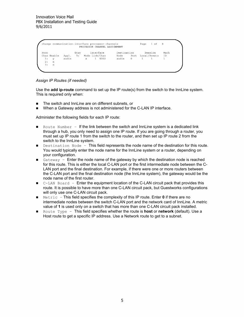
Assign IP Routes (if needed) Use the add ip-route command to set up the IP route(s) from the switch to the InnLine system. This is required only when:
The switch and InnLine are on different subnets, or When a Gateway address is not administered for the C-LAN IP interface.
Administer the following fields for each IP route:
Route Number – If the link between the switch and InnLine system is a dedicated link through a hub, you only need to assign one IP route. If you are going through a router, you must set up IP route 1 from the switch to the router, and then set up IP route 2 from the switch to the InnLine system.
Destination Node – This field represents the node name of the destination for this route. You would typically enter the node name for the InnLine system or a router, depending on your configuration.
Gateway – Enter the node name of the gateway by which the destination node is reached for this route. This is either the local C-LAN port or the first intermediate node between the C-LAN port and the final destination. For example, if there were one or more routers between the C-LAN port and the final destination node (the InnLine system), the gateway would be the node name of the first router.
C-LAN Board – Enter the equipment location of the C-LAN circuit pack that provides this route. It is possible to have more than one C-LAN circuit pack, but Guestworks configurations will only use one C-LAN circuit pack.
Metric – This field specifies the complexity of this IP route. Enter 0 if there are no intermediate nodes between the switch C-LAN port and the network card of InnLine. A metric value of 1 is used only on a switch that has more than one C-LAN circuit pack installed.
Route Type – This field specifies whether the route is host or network (default). Use a Host route to get a specific IP address. Use a Network route to get to a subnet.
Innovation Voice Mail PBX Installation and Testing Guide 9/6/2011
6
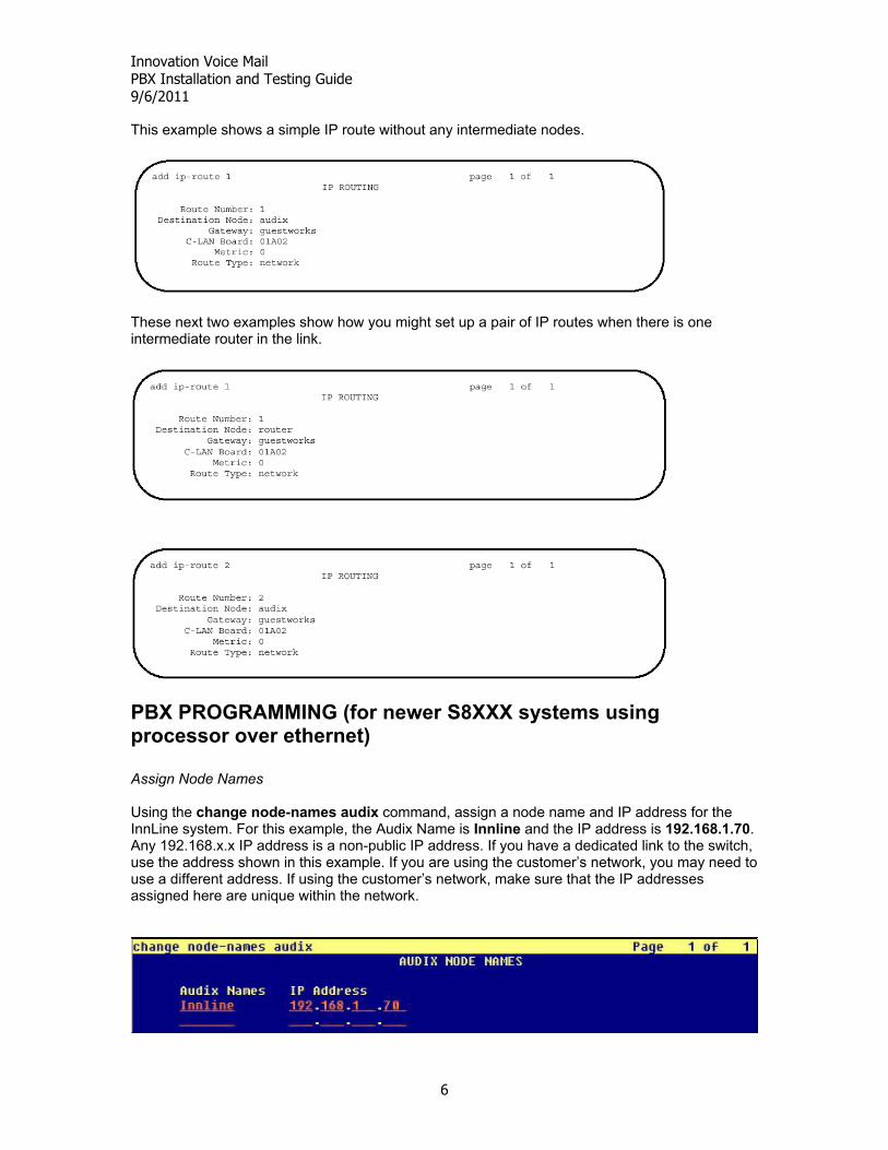
This example shows a simple IP route without any intermediate nodes.
These next two examples show how you might set up a pair of IP routes when there is one intermediate router in the link.
PBX PROGRAMMING (for newer S8XXX systems using processor over ethernet) Assign Node Names Using the change node-names audix command, assign a node name and IP address for the InnLine system. For this example, the Audix Name is Innline and the IP address is 192.168.1.70. Any 192.168.x.x IP address is a non-public IP address. If you have a dedicated link to the switch, use the address shown in this example. If you are using the customer’s network, you may need to use a different address. If using the customer’s network, make sure that the IP addresses assigned here are unique within the network.
Innovation Voice Mail PBX Installation and Testing Guide 9/6/2011
7
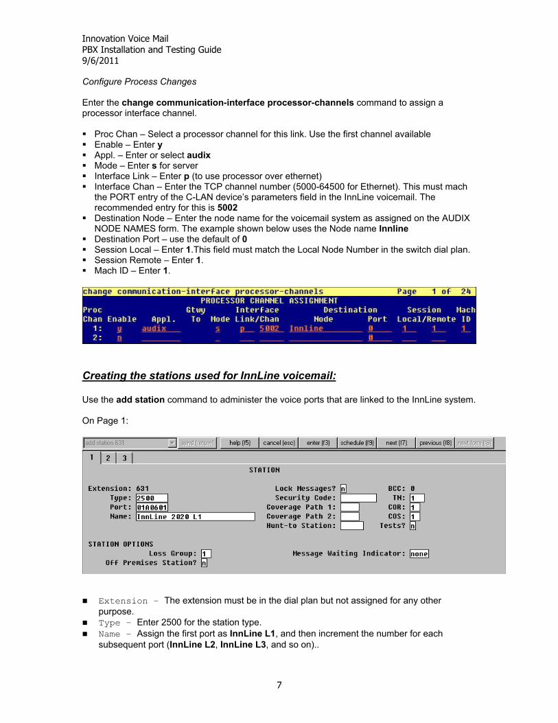
Configure Process Changes Enter the change communication-interface processor-channels command to assign a processor interface channel. Proc Chan – Select a processor channel for this link. Use the first channel available Enable – Enter y Appl. – Enter or select audix Mode – Enter s for server Interface Link – Enter p (to use processor over ethernet) Interface Chan – Enter the TCP channel number (5000-64500 for Ethernet). This must mach
the PORT entry of the C-LAN device’s parameters field in the InnLine voicemail. The recommended entry for this is 5002
Destination Node – Enter the node name for the voicemail system as assigned on the AUDIX NODE NAMES form. The example shown below uses the Node name Innline
Destination Port – use the default of 0 Session Local – Enter 1.This field must match the Local Node Number in the switch dial plan. Session Remote – Enter 1. Mach ID – Enter 1.
Creating the stations used for InnLine voicemail: Use the add station command to administer the voice ports that are linked to the InnLine system. On Page 1:
Extension – The extension must be in the dial plan but not assigned for any other purpose.
Type – Enter 2500 for the station type. Name – Assign the first port as InnLine L1, and then increment the number for each
subsequent port (InnLine L2, InnLine L3, and so on)..
Innovation Voice Mail PBX Installation and Testing Guide 9/6/2011
8
COR – Use the same COR for the voice ports that you use for the hunt groups. The COR should have the FRL set to 1 and should not allow access to trunk group CORs.
COS – Use a COS that allows data privacy. On Page 2:
LWC Reception – Enter audix. LWC Activation – Enter n. Switchhook Flash – Enter y. Distinctive Audible Alerting – Enter n. Adjunct Supervision – Enter y. This provides disconnect supervision on the voicemail
station ports. AUDIX Name – This field (not shown in the example above) is on newer versions of Avaya Communication Manager. Enter the name that is assigned in the AUDIX NODE NAMES form.
Innovation Voice Mail PBX Installation and Testing Guide 9/6/2011
9
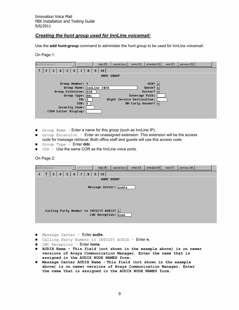
Creating the hunt group used for InnLine voicemail: Use the add hunt-group command to administer the hunt group to be used for InnLine voicemail. On Page 1:
Group Name – Enter a name for this group (such as InnLine IP). Group Extension – Enter an unassigned extension. This extension will be the access
code for message retrieval. Both office staff and guests will use this access code. Group Type – Enter ddc COR – Use the same COR as the InnLine voice ports.
On Page 2:
Message Center – Enter audix. Calling Party Number to INTUITY AUDIX – Enter n. LWC Reception – Enter none. AUDIX Name - This field (not shown in the example above) is on newer versions of Avaya Communication Manager. Enter the name that is assigned in the AUDIX NODE NAMES form.
Message Center AUDIX Name - This field (not shown in the example above) is on newer versions of Avaya Communication Manager. Enter the name that is assigned in the AUDIX NODE NAMES form.
Innovation Voice Mail PBX Installation and Testing Guide 9/6/2011
10
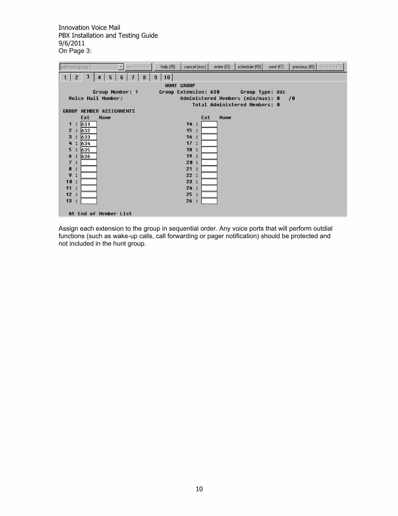
On Page 3:
Assign each extension to the group in sequential order. Any voice ports that will perform outdial functions (such as wake-up calls, call forwarding or pager notification) should be protected and not included in the hunt group.
Innovation Voice Mail PBX Installation and Testing Guide 9/6/2011
11
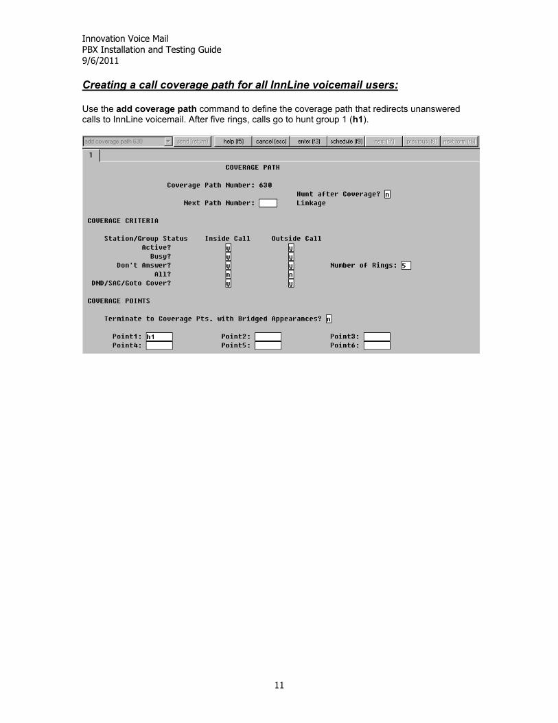
Creating a call coverage path for all InnLine voicemail users: Use the add coverage path command to define the coverage path that redirects unanswered calls to InnLine voicemail. After five rings, calls go to hunt group 1 (h1).
Innovation Voice Mail PBX Installation and Testing Guide 9/6/2011
12
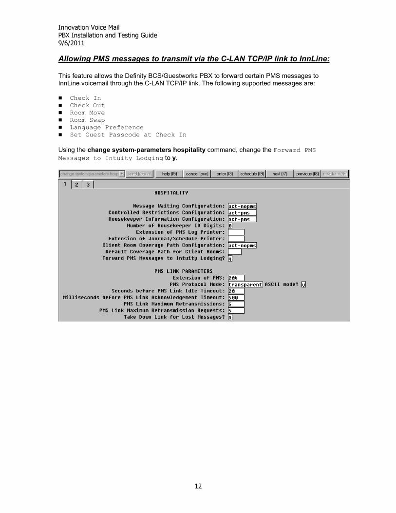
Allowing PMS messages to transmit via the C-LAN TCP/IP link to InnLine: This feature allows the Definity BCS/Guestworks PBX to forward certain PMS messages to InnLine voicemail through the C-LAN TCP/IP link. The following supported messages are:
Check In Check Out Room Move Room Swap Language Preference Set Guest Passcode at Check In Using the change system-parameters hospitality command, change the Forward PMS Messages to Intuity Lodging to y.
Innovation Voice Mail PBX Installation and Testing Guide 9/6/2011
13
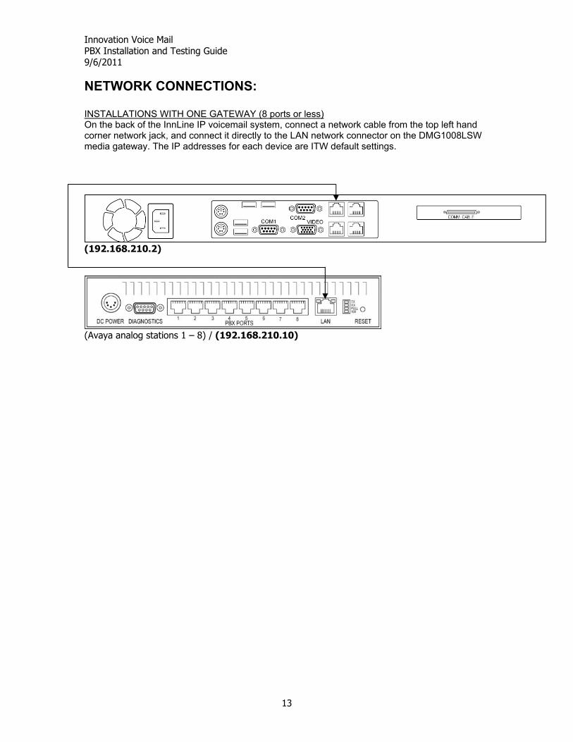
NETWORK CONNECTIONS: INSTALLATIONS WITH ONE GATEWAY (8 ports or less) On the back of the InnLine IP voicemail system, connect a network cable from the top left hand corner network jack, and connect it directly to the LAN network connector on the DMG1008LSW media gateway. The IP addresses for each device are ITW default settings.
(192.168.210.2)
(Avaya analog stations 1 – 8) / (192.168.210.10)
Innovation Voice Mail PBX Installation and Testing Guide 9/6/2011
14
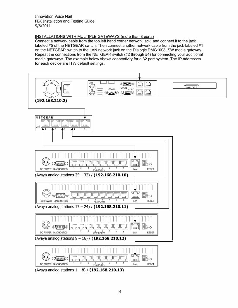
INSTALLATIONS WITH MULTIPLE GATEWAYS (more than 8 ports) Connect a network cable from the top left hand corner network jack, and connect it to the jack labeled #5 of the NETGEAR switch. Then connect another network cable from the jack labeled #1 on the NETGEAR switch to the LAN network jack on the Dialogic DMG1008LSW media gateway. Repeat the connections from the NETGEAR switch (#2 through #4) for connecting your additional media gateways. The example below shows connectivity for a 32 port system. The IP addresses for each device are ITW default settings.
(192.168.210.2)
(Avaya analog stations 25 – 32) / (192.168.210.10)
(Avaya analog stations 17 – 24) / (192.168.210.11)
(Avaya analog stations 9 – 16) / (192.168.210.12)
(Avaya analog stations 1 – 8) / (192.168.210.13)
Innovation Voice Mail PBX Installation and Testing Guide 9/6/2011
15
PBX TERMINATIONS: The Dialogic DMG1008LSW has 8 RJ14 style connectors on the back. Connect the Avaya analog stations to the gateway’s RJ14 jacks numbered 1 through 8 using standard line cords.
As you connect each line cord, the Port Status led indicator for that line will change from red to green. This indicates that Carrier is present.
Port Status definitions:
• Steady Green – indicates that Carrier is present. • Flashing Green – indicates that there is activity on the port. • Steady Yellow – Hardware Carrier is present, but no software communication. • Flashing Yellow – External power detected, but port cannot gain carrier • Steady Red – Indicates that no Carrier is present and no external power detected
Innovation Voice Mail PBX Installation and Testing Guide 9/6/2011
16
VOICEMAIL PROGRAMMING:
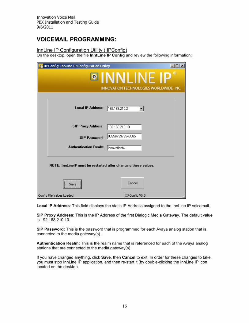
InnLine IP Configuration Utility (IIPConfig) On the desktop, open the file InntLine IP Config and review the following information:
Local IP Address: This field displays the static IP Address assigned to the InnLine IP voicemail. SIP Proxy Address: This is the IP Address of the first Dialogic Media Gateway. The default value is 192.168.210.10. SIP Password: This is the password that is programmed for each Avaya analog station that is connected to the media gateway(s). Authentication Realm: This is the realm name that is referenced for each of the Avaya analog stations that are connected to the media gateway(s) If you have changed anything, click Save, then Cancel to exit. In order for these changes to take, you must stop InnLine IP application, and then re-start it (by double-clicking the InnLine IP icon located on the desktop.
Innovation Voice Mail PBX Installation and Testing Guide 9/6/2011
17
Voice Port Configuration Go to Do > Configure System > Voice Ports and double the Port Wizard (choose Yes to run the port wizard at this time
If your Avaya analog stations are concurrent, enter the first number in BOTH the 1st Extension and Sip Alias fields. Click OK. The port wizard will now automatically populate these fields in the other Port Screens IMPORTANT NOTE: The last port is always set to Out-Bound only. This port needs to be protected from inbound calls. Remove that Avaya analog station from the hunt-group. If you require additional ports to perform outbound events, then these Avaya analog stations need to be removed from the hunt-group as well.
Innovation Voice Mail PBX Installation and Testing Guide 9/6/2011
18
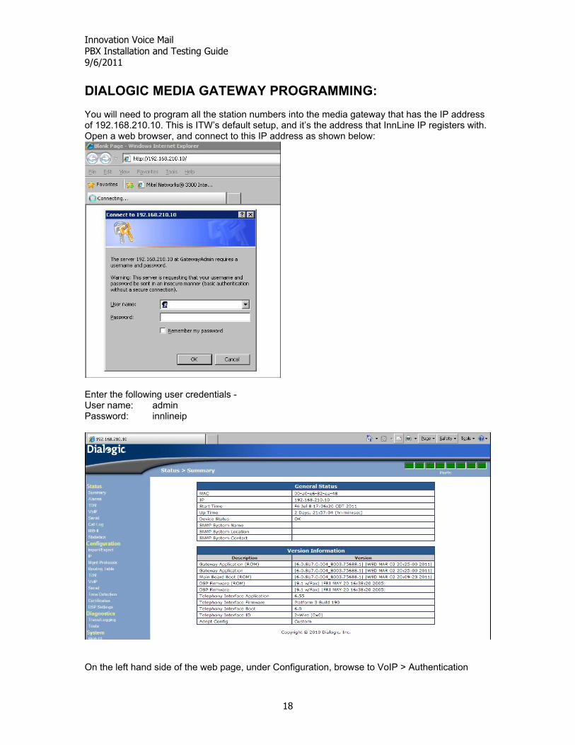
DIALOGIC MEDIA GATEWAY PROGRAMMING: You will need to program all the station numbers into the media gateway that has the IP address of 192.168.210.10. This is ITW’s default setup, and it’s the address that InnLine IP registers with. Open a web browser, and connect to this IP address as shown below:
Enter the following user credentials - User name: admin Password: innlineip
On the left hand side of the web page, under Configuration, browse to VoIP > Authentication
Innovation Voice Mail PBX Installation and Testing Guide 9/6/2011
19
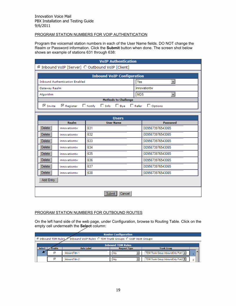
PROGRAM STATION NUMBERS FOR VOIP AUTHENTICATION Program the voicemail station numbers in each of the User Name fields. DO NOT change the Realm or Password information. Click the Submit button when done. The screen shot below shows an example of stations 631 through 638:
PROGRAM STATION NUMBERS FOR OUTBOUND ROUTES On the left hand side of the web page, under Configuration, browse to Routing Table. Click on the empty cell underneath the Select column:
Innovation Voice Mail PBX Installation and Testing Guide 9/6/2011
20
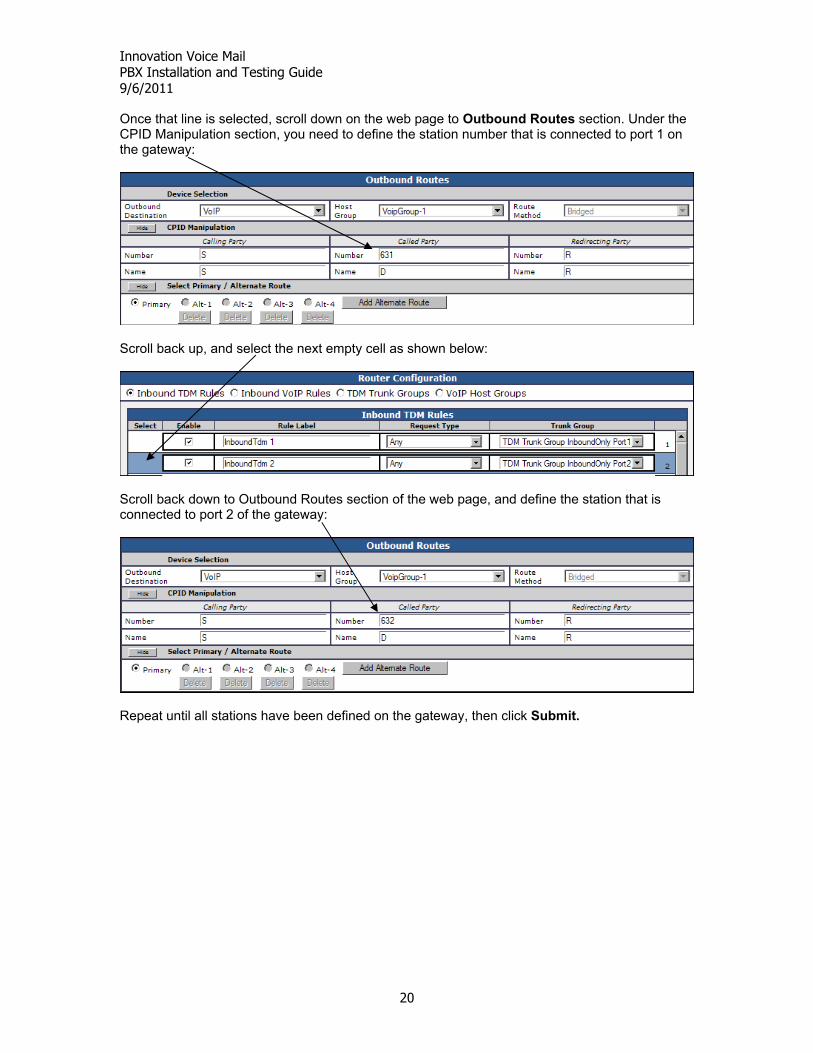
Once that line is selected, scroll down on the web page to Outbound Routes section. Under the CPID Manipulation section, you need to define the station number that is connected to port 1 on the gateway:
Scroll back up, and select the next empty cell as shown below:
Scroll back down to Outbound Routes section of the web page, and define the station that is connected to port 2 of the gateway:
Repeat until all stations have been defined on the gateway, then click Submit.
Innovation Voice Mail PBX Installation and Testing Guide 9/6/2011
21
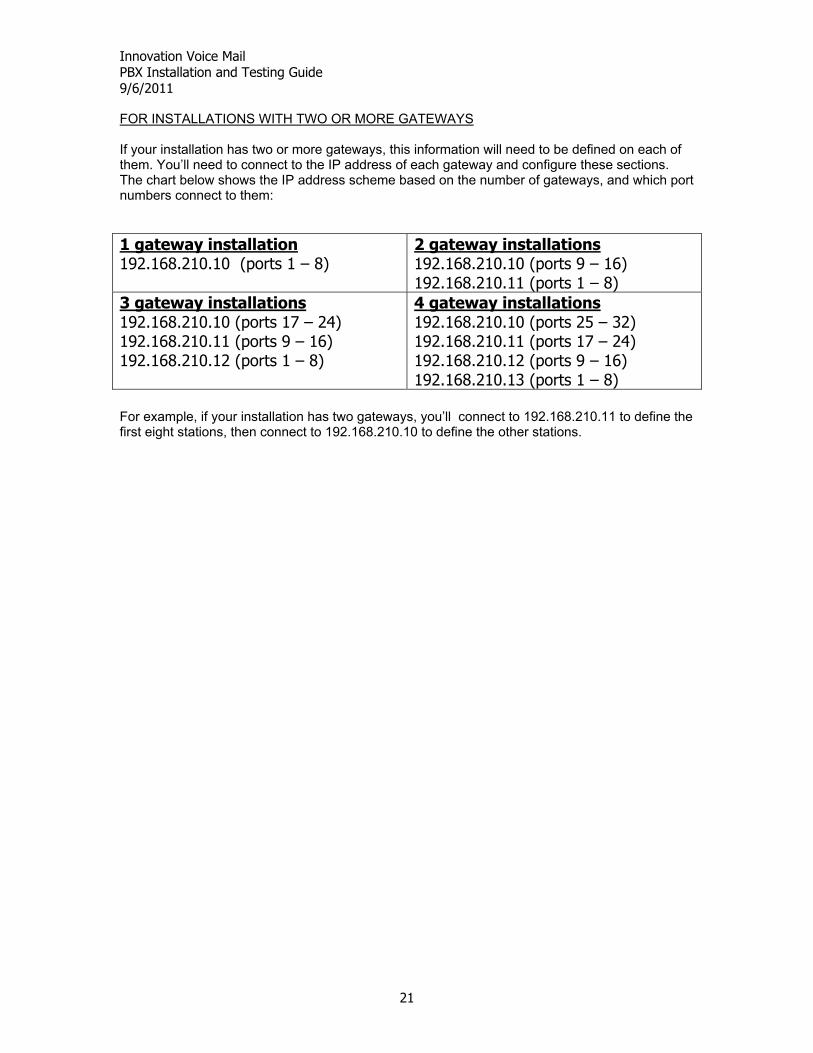
FOR INSTALLATIONS WITH TWO OR MORE GATEWAYS If your installation has two or more gateways, this information will need to be defined on each of them. You’ll need to connect to the IP address of each gateway and configure these sections. The chart below shows the IP address scheme based on the number of gateways, and which port numbers connect to them: 1 gateway installation 192.168.210.10 (ports 1 – 8)
For example, if your installation has two gateways, you’ll connect to 192.168.210.11 to define the first eight stations, then connect to 192.168.210.10 to define the other stations.
Innovation Voice Mail PBX Installation and Testing Guide 9/6/2011
22
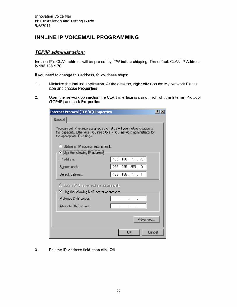
INNLINE IP VOICEMAIL PROGRAMMING TCP/IP administration: InnLine IP’s CLAN address will be pre-set by ITW before shipping. The default CLAN IP Address is 192.168.1.70 If you need to change this address, follow these steps: 1. Minimize the InnLine application. At the desktop, right click on the My Network Places
icon and choose Properties 2. Open the network connection the CLAN interface is using. Highlight the Internet Protocol
(TCP/IP) and click Properties
3. Edit the IP Address field, then click OK
Innovation Voice Mail PBX Installation and Testing Guide 9/6/2011
23
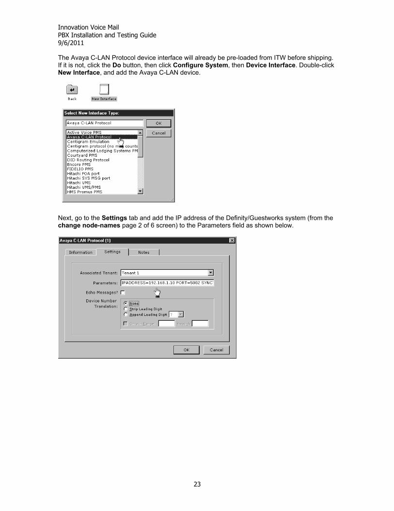
The Avaya C-LAN Protocol device interface will already be pre-loaded from ITW before shipping. If it is not, click the Do button, then click Configure System, then Device Interface. Double-click New Interface, and add the Avaya C-LAN device.
Next, go to the Settings tab and add the IP address of the Definity/Guestworks system (from the change node-names page 2 of 6 screen) to the Parameters field as shown below.
Innovation Voice Mail PBX Installation and Testing Guide 9/6/2011
24
Connecting the TCP/IP link between Avaya and InnLine IP: Connect the 259A Adapter (with the network crossover cable already attached) to the back side of the TN799 C-LAN circuit pack. Then connect from the system to InnLine IP network connection you just configured (back on page 20) using a straight through network cable. If you are using a newer Avaya Communication Manager (such as the S8300), connect a straight through network cable to the Layer 2 switch the communication manager is using. Ping the TCP/IP link between Avaya and InnLine IP: Testing from the InnLine side: Minimize the InnLine IP application and go to a Command Prompt. Next, type the word “ping” and the IP address of the Avaya system. Example:
Innovation Voice Mail PBX Installation and Testing Guide 9/6/2011
25
Testing from the Avaya side:
Use the command ping ip-address plus the IP address of InnLine. Example:
TESTING Testing disconnect supervision When a caller is connected to voicemail and hangs up, the Avaya PBX will provide a momentary open. This is the voicemail systems indication to disconnect. Test this by placing a call from any station to the voicemail system. After voicemail answers, hang up. On the gateway, look at the line that the call came in on. If the green led stops flashing, returning to steady green within a few seconds after hanging up, then disconnect supervision is working properly. Call each of the remaining voicemail stations, (hanging up after each port answers) and watch to see if the gateway led goes from flashing green to steady green. This test should be performed station to station and trunk to station. For a trunk to station test, call the hotel’s main number, and have the attendant transfer you to voicemail. When voicemail answers, hang-up and watch the gateways led status as described above. If disconnect supervision does not work, make sure that Adjunct Supervision (on page 2 of the form) set to a “y”.
Innovation Voice Mail PBX Installation and Testing Guide 9/6/2011
26
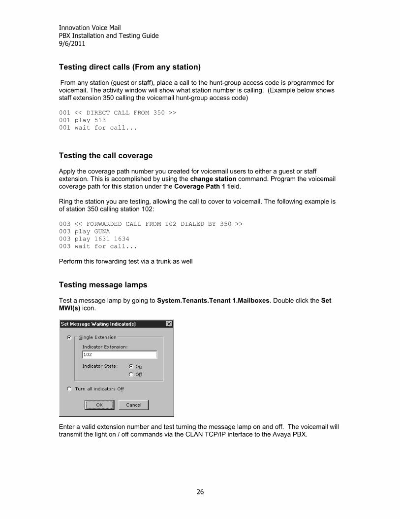
Testing direct calls (From any station) From any station (guest or staff), place a call to the hunt-group access code is programmed for voicemail. The activity window will show what station number is calling. (Example below shows staff extension 350 calling the voicemail hunt-group access code) 001 << DIRECT CALL FROM 350 >> 001 play 513 001 wait for call... Testing the call coverage Apply the coverage path number you created for voicemail users to either a guest or staff extension. This is accomplished by using the change station command. Program the voicemail coverage path for this station under the Coverage Path 1 field. Ring the station you are testing, allowing the call to cover to voicemail. The following example is of station 350 calling station 102: 003 << FORWARDED CALL FROM 102 DIALED BY 350 >> 003 play GUNA 003 play 1631 1634 003 wait for call... Perform this forwarding test via a trunk as well Testing message lamps Test a message lamp by going to System.Tenants.Tenant 1.Mailboxes. Double click the Set MWI(s) icon.
Enter a valid extension number and test turning the message lamp on and off. The voicemail will transmit the light on / off commands via the CLAN TCP/IP interface to the Avaya PBX.
Innovation Voice Mail PBX Installation and Testing Guide 9/6/2011
27
Other Information When you take the InnLine application off line, InnLine will transmit to C-LAN that the voicemail extensions will not be available to receive calls. InnLine transmits this status message for each voicemail port. Users calling the voicemail access code during this time will receive a fast busy signal from the Avaya. These messages may be monitored on the Interface Activity portion of the Interface: Avaya C-LAN Protocol section.
A “0” at the end of the status message represents that InnLine is communicating to C-LAN that the voicemail extension will be unavailable for calls.
A “1” at the end of the status message represents that InnLine is communicating to C-LAN that the voicemail extension is now available for calls. Whenever the TCP/IP link between InnLine and the Avaya is disconnected, and then re-established (i.e. when the InnLine computer is restarted), C-LAN will transmit to InnLine a message waiting resync command for every station number programmed in the PBX. END OF DOCUMENT