Issue 3.2 Copyright © 2009 Avaya Inc. All Rights Reserved. 1
AVAYA IP VOICE QUALITY NETWORK
REQUIREMENTS
White paper
Issue 3.2
August 2009
Developed by:
Avaya, Inc. Westminster, Colorado
Issue 3.2 Copyright © 2009 Avaya Inc. All Rights Reserved. 2
Copyright 2009 Avaya, Inc.
All Rights Reserved Printed in U.S.A.
TRADEMARK NOTICE
Avaya and the Avaya Logo are trademarks of Avaya Inc. and may
be registered in certain jurisdictions. All trademarks identified by
® or ™ are registered trademarks and trademarks respectively of
Avaya Inc. All other trademarks are the property of their
respective owners.
NOTICE
While reasonable efforts were made to ensure the information in this document was complete
and accurate at the time of printing, Avaya can assume no responsibility for any errors.
Changes and corrections to the information contained in this document may be incorporated
into future releases.
Issue 3.2 Copyright © 2009 Avaya Inc. All Rights Reserved. 3
Contents
1 Document Summary ............................................................................................ 4
Avaya IP Voice Quality Network Requirements ............................................................... 7
Explanations ............................................................................................................ 7
2 Introduction ........................................................................................................ 7
3 Defining Quality .................................................................................................. 8
3.1 What is Quality? ............................................................................................. 8
3.2 What is Voice Quality? ..................................................................................... 8
4 Prioritizing Voice Traffic ........................................................................................ 8
4.1 Understanding the difference between CoS and QoS ........................................... 8
4.2 Using Ports .................................................................................................... 9
4.3 Using DSCP (or TOS) ....................................................................................... 9
4.4 Using IEEE 802.1 p/Q ...................................................................................... 9
4.5 Using VLANs ................................................................................................. 10
5 Network Parameters .......................................................................................... 10
5.1 Network Packet Delay .................................................................................... 10
5.2 Network Jitter ............................................................................................... 11
5.3 Packet Loss .................................................................................................. 12
5.4 Network Packet Mis-Order .............................................................................. 12
5.5 Transcoding ................................................................................................. 13
5.6 Echo ............................................................................................................ 13
5.7 Silence Suppression and Voice Activity Detection .............................................. 13
5.8 Network Duplex ............................................................................................ 14
5.9 Codec Selection ............................................................................................ 14
6 Bearer Bandwidth .............................................................................................. 14
6.1 WAN Bandwidth Comparison .......................................................................... 15
6.2 LAN Bandwidth Comparison ........................................................................... 15
7 Network Assessment .......................................................................................... 16
8 PC Considerations using Avaya’s One X Communicator ........................................... 18
9 Bandwidth Requirements .................................................................................... 19
9.1 Bandwidth Requirements using IP SoftPhone (or IP Agent) ................................ 19
10 Other Elements that Affect VoIP ....................................................................... 20
10.1 WAN Considerations ................................................................................... 20
10.2 VPN (Virtual Private Network) ..................................................................... 20
10.3 Frame Relay ............................................................................................. 20
10.4 Multi Protocol Label Switching (MPLS) .......................................................... 21
10.5 Network Address Translation (NAT) ............................................................. 21
Appendix A .............................................................................................................. 22
Network Design Recommendations ........................................................................... 22
Best practices .......................................................................................................... 22
Common issues ........................................................................................................ 23
Appendix B .............................................................................................................. 25
Overview................................................................................................................. 25
Issue and Alternatives .............................................................................................. 26
Additional Frame Relay Information ............................................................................ 26
Appendix C .............................................................................................................. 27
VoIP without using NAT ........................................................................................... 27
Issue 3.2 Copyright © 2009 Avaya Inc. All Rights Reserved. 4
Avaya IP Voice Quality Network Requirements
1 Document Summary This document contains basic network requirements that are foundational for good voice
quality when using Avaya IP products and solutions over a data network. No document can
satisfy the detailed needs of every network, and therefore, this paper serves only as a
starting point. The document summary provides a short list of networking requirements,
allowances and recommendations. Use this page as a checklist to determine if the network
meets the minimum requirements for implementing Voice over Internet Protocol (VoIP) with
acceptable quality. The rest of the document contains basic networking and telephony
concepts for those who haven’t been exposed to a converged implementation. It also explains
why VoIP applications can yield poor results when data traffic on the same network doesn’t
seem to have problems.
Voice quality is always a subjective topic. Defining ―good‖ voice quality varies with business
needs, cultural differences, customer expectations, etc. The requirements below are based
on the ITU-T, EIA/TIA guidelines and extensive testing at Avaya Labs. Note that while
Avaya’s requirements will meet or exceed most customer quality expectations, the final
determination of acceptable voice quality lies with the customer’s definition of quality and the
design, implementation and monitoring of the end to end data network.
Quality is not measured by one discrete value where a number where 8 is good and 9 is bad.
There is a tradeoff between real-world limits and acceptable voice quality. Lower delay, jitter
and packet loss values can produce the best voice quality, but may also come with a cost to
upgrade the network infrastructure to get to the lower network values. Another real-world
limit is the inherent WAN delay over a trunk linking, for example, the U.S. West coast to
India. This link could easily add a fixed 150ms delay into the overall delay budget and is
beyond the control of an enterprise. Perfectly acceptable voice quality is attainable but will
not be ―toll‖ quality. Therefore, Avaya presents a tiered choice of values that make up the
requirements.
Voice quality is made up of both objective and subjective contributors. The objective
elements in assessing VoIP quality are delay, jitter and packet loss. These elements are
defined and influenced in the transport of IP both within and outside an enterprise. To ensure
good and consistent levels of voice quality, Avaya suggests the following network parameters.
Note that these suggestions hold true for LAN only and LAN/WAN connectivity. All
requirement values listed are measured between endpoints because this document assumes
that IP telephony has not yet been implemented. All values therefore reflect the network’s
performance without endpoint consideration. This is why there is, seemingly, a discrepancy
between the well-known ITU-T value for one-way delay and the values listed. The ITU-T
values are end-to-end values; from the mouth of the transmitter to the ear of the receiver.
The network requirements listed are meant for the network only – between endpoints - so
that your business data network can be assessed and modified, if need be, for successful
deployment of real time applications like voice and video. The requirement values are also
useful for ongoing network monitoring by IT staff. Upward trends in delay, jitter or packet
loss serve as a warning of potential voice quality problems.
Also, please note that ―Business Communication Quality‖ is defined as slightly less than toll
but far better than cell-phone quality. This is the tier where most businesses experience the
best trade-off between voice quality and network infrastructure costs.
Requirements for objective factors:
Issue 3.2 Copyright © 2009 Avaya Inc. All Rights Reserved. 5
Network delay: One-way Between endpoints,
o 80ms (milliseconds) delay or less can, but may not, yield toll quality.
o 80ms to 180ms delay can give business communication quality. This is far
better than cell-phone quality and in fact is very well suited for the majority of
businesses.
o Delays exceeding 180ms may still be quite acceptable depending on customer
expectations, analog trunks used, codec type, etc.
(See section 4.1 for more information)
Network jitter: Jitter is a measure of the variability of delay. Between endpoints:
o Toll quality suggests average jitter be less than ½ the packet payload. This
value has some latitude depending on the type of service the jitter buffer has in
relationship to other buffers, packet size used, etc.
(See section 4.2 for more information)
Network packet loss: The maximum loss of packets (or frames). Between
endpoints:
o 1% or less can yield toll quality depending on many factors.
o 3% or less should give Business communications quality. Again, this quality is
much better than cell-phone quality.
o More than 3% may be acceptable for voice but may interfere with signaling.
(See section 4.3 for more information)
Recommendations: Avaya highly recommends consideration of the following list of Best
Practices when implementing VoIP.
QoS/CoS: Quality of Service (QoS) for voice packets is obtained only after a Class of
Service (CoS) mechanism tags and Network elements treat voice packets as having
priority over data packets. Networks with periods of congestion can still provide
excellent voice quality when using a QoS/CoS policy. Switched networks may use
IEEE 802.1p/Q. Routed networks should use DSCP (DiffServ Code Points). Mixed
networks may use both as a best practice. Port priority can also be used to enhance
DiffServ and IEEE 802.1p/Q. Even networks with plentiful bandwidth should
implement CoS/QoS to protect voice communications from periods of unusual
congestion such as from a computer virus. See sections 3.1 - 3.4 for more information.
Switched Network: A fully switched LAN network is a network that allows full duplex
and full endpoint bandwidth for every endpoint that exists on that LAN. Although VoIP
systems can work in a shared (hubs or bussed) LAN, Avaya recommends the
consistently high results a switched network lends to VoIP.
Network Assessment: A Basic Network Readiness Assessment Offer from Avaya is
vital to a successful implementation of VoIP products and solutions. Contact the Avaya
Issue 3.2 Copyright © 2009 Avaya Inc. All Rights Reserved. 6
representative or authorized dealer to review or certify your network. Section 7
―Network Assessment‖ explains the options available with this offer.
VLANs: Placing voice packets on a separate VLAN (subnet) from data packets is a
generally accepted practice to reduce both broadcast and data traffic from contending
for the same bandwidth as voice. Other benefits become available when using VLANs,
but there may be a substantial cost for initial administration and maintenance. Section
3.5 ―Using VLANs‖ further explains this concept.
Cautions: Avaya also recommends caution when using the following:
NAT: Be cautious when using NAT (Network Address Translation). Some
implementations using VoIP endpoints behind NAT fail because H.323 messages
contain multiple instances of the same IP address in a given message, and NAT can fail
to find and translate all of them. Avaya’s Communication Manager will work
seamlessly with any static NAT application even if that NAT is not H.323 aware. See
section 10.4, "Network Address translation" and Appendix C for more information on
using NAT.
Analog Dial-Up: Be careful using analog dial-up (bandwidth 56K) to connect two
locations. Upstream bandwidth is limited to a maximum of 56K, but in most cases is
less. This results in insufficient bandwidth to provide toll-quality voice. Some codecs
and network parameters provide connections that are acceptable, but consider each
connection individually.
VPN: Use Virtual Private Network (VPN) cautiously with VoIP applications. Older
systems can have large delays due to encryption, decryption and additional
encapsulation. Many hardware-based products encrypt at near wire speed and can be
used. Additionally, if the VPN routes over the Internet without SLAs in place, sufficient
quality for voice cannot be guaranteed unless delay, jitter and packet loss adhere to
the parameters listed above. See section 9.2 ―VPN (Virtual Private Network)‖ for more
information.
Issue 3.2 Copyright © 2009 Avaya Inc. All Rights Reserved. 7
Avaya IP Voice Quality Network Requirements Explanations
2 Introduction Voice over Internet Protocol (VoIP) is the convergence of traditional voice onto an IP data
network to provide better application integration by using a common protocol and to lower
costs by using ISPs and melding separate support staffs. Other real-time traffic, such as
uncompressed video and streaming audio, is also converging onto data networks.
VoIP is very complex because it involves components of both the data and voice worlds.
Historically, these worlds have used two different networks, two different support
organizations and two different philosophies. The voice network has always been separate
from the data network because of the protocols used and the characteristics of voice
applications are very different from those of data applications.
Traditionally, voice calls have had their own dedicated bandwidth throughout the circuit
switched network. This provided an environment where ―five nine‖ of reliability became the
standard. Interactive voice traffic is sensitive to delay and jitter but can tolerate some packet
loss, problems that were rarely an issue with circuit switching.
The data network, on the other hand, is packet switched. Data is less sensitive to delay and
jitter, but cannot tolerate loss. The data philosophy has centered on providing reliable data
transmission over unreliable media, almost regardless of delay. Bandwidth in the data world
is largely shared, so congestion and delay are often present and can cause problems for
multimedia applications such as voice.
The factors that affect the quality of data transmission are different from those affecting the
quality of voice transmission. For example, data is generally not affected by delay. Voice
transmissions, on the other hand, are degraded by relatively small amounts of delay and
cannot be retransmitted. Additionally, a tiny amount of packet (data) loss does not affect
voice quality at the receiver’s ear, but even a small loss of data can corrupt an entire file or
application. In some cases, introducing VoIP to a high performing data network can yield
very poor voice quality.
Therefore, implementing VoIP requires attention to many factors, including:
Delay Jitter
Packet loss Packet mis-order
Available
bandwidth Packet prioritization
Network design Endpoint audio characteristics
(sound card, microphone,
earpiece, etc.)
Duplex Transcoding
Echo Silence suppression
Codec selection Router and data-switch
configuration
Reliability Scalability
Manageability WAN protocols
QoS/CoS policy Encryption/Decryption
Issue 3.2 Copyright © 2009 Avaya Inc. All Rights Reserved. 8
This document provides basic network guidelines to ensure good voice quality when
implementing VoIP. This document also examines some of the more important components
that affect VoIP and gives suggestions to help avoid problems during implementation.
3 Defining Quality
3.1 What is Quality?
Quality is a word that is used by almost all manufacturing and service providers. Quality,
however, is an ambiguous term representing superiority of that product or service. But
quality can mean different things to different people.
Consider Bill, a person who wants to buy a quality vehicle. Bill goes to a dealership and sees
a luxury sports sedan. It is a quality vehicle. The stitching on the leather seats is uniformly
0.2‖ apart on all seams. The finish consists of 10 color coats and 2 high-polymer sealant
coats. The fit between the doors and the body is consistently 0.167‖. Bill buys the luxury
sports sedan and is happy with the ―quality‖.
Now consider Trish, a person who also wants to buy a quality vehicle. Trish lives in rugged
mountain terrain, miles from anyone and must cross a boulder field just to get to work. Trish
is looking for a vehicle that has high ground clearance, a stiff suspension and 4-wheel drive to
get her to town and back – consistently without breaking down. Trish buys a Sport Utility
Vehicle and is happy with the ―quality‖. Trish doesn’t care about the stitching on the seats,
the gloss of the paint or the extreme exactness of the fit of the doors to the body. Trish
knows the paint will soon have chips, the body will get dents and the interior will stain.
Quality, in the above examples, consists of entirely different values. Therefore, what one
person values in quality may be almost irrelevant to another. Both Bill and Trish purchased
quality vehicles that have superior, but different features.
3.2 What is Voice Quality?
Defining voice quality is also difficult because the values of a small business can be greatly
different than a business that is larger or located in another culture or country. This is why
Avaya presents choices using a tiered system of network requirements. One number for
delay or jitter or packet loss cannot satisfy all customers in all businesses and in all cultures.
Ultimately, each business must decide if quality voice using VoIP requires the first tier of
values or other tiered values specified in this paper.
4 Prioritizing Voice Traffic In order for a VoIP solution to function well, the network must be able to give voice packets
priority over ordinary data packets and sufficient bandwidth must always be available.
Avaya’s products for VoIP—Communication Manager™ Software include several standard
strategies to prioritize voice traffic. These strategies include using class of service (CoS),
prioritizing ports, prioritizing services, and using IEEE 802.1p/Q to set the priority bits. Avaya
products are designed to work with most other popular switches and routers using open
standards to provide end-to-end voice prioritization.
4.1 Understanding the difference between CoS and QoS
Class of Service (CoS) is a classification method only. CoS does NOT ensure a level of Quality
of Service (QoS), but is the method used by queuing mechanisms to limit delay and other
Issue 3.2 Copyright © 2009 Avaya Inc. All Rights Reserved. 9
factors to improve QoS. Most CoS strategies assign a priority level, usually 0–7 or 0-63, to a
frame or packet respectively. Common CoS models include the IP TOS (Type Of Service)
byte, Differentiated Services Code Point (DiffServ or DSCP, defined in RFC 2474 and others)
and the IEEE 802.1p/Q.
Quality of Service (QoS) involves giving preferential treatment through queuing, bandwidth
reservation, or other methods based on attributes of the packet, such as CoS priority. A
service quality is then negotiated. Examples of QoS are CBWFQ (Class Based Weighted Fair
Queuing), RSVP (RESERVATION Protocol - RFC 2205), MPLS, (Multi Protocol Label Switching -
RFC 1117 and others).
CoS, or tagging, is totally ineffective in the absence of QoS because it can only mark data.
QoS relies on those tags or filters to give priority to data streams.
4.2 Using Ports
One prioritization scheme assigns priority based on the UDP (User Datagram Protocol) port
numbers used by the voice packets. This scheme allows the use of network equipment to
prioritize all packets from a port range. UDP is used to transport voice packets through the
LAN because, unlike TCP, it is not connection-based. Because of the human ear’s sensitivity
to delay, it is better to drop packets rather than retransmit voice in a real time environment
so a connectionless protocol is preferable to a connection-based protocol. By using
Communication Manager Software, users can define a UDP port range for voice priority.
Routers and layer 3 data switches can then use these ports to distinguish priority traffic. This
priority traffic can be voice packets (UDP), signaling packets (TCP) or both. This is an OSI
model layer-4 solution and works on data coming to and from the specified ports or a port
range.
4.3 Using DSCP (or TOS)
The DSCP prioritization scheme redefined the original Type of Service (TOS) byte in the IP
header by combining the first six bits into 64 possible combinations. This use of the TOS byte
is used by Communication Manager Software, IP Telephones, and other network elements
such as routers and switches in the LAN and WAN. A DSCP of 46 (101110) is suggested for
the expedited forwarding of voice packets. However, with Communication Manager, one can
set any DSCP value as desired to work with a company’s QoS scheme.
Note that older routers may require a DSCP setting of 40 (101000), which is backward
compatible to the original TOS byte definition of critical. But again, Avaya products and
software allows users to set any of the 64 possible DSCP values to work with your voice
quality policy. The TOS byte is an OSI model layer-3 solution and works on IP packets on the
LAN and possibly the WAN depending on the service provider.
4.4 Using IEEE 802.1 p/Q
Yet another prioritization scheme is the IEEE 802.1Q standard, which uses four bytes to
augment the layer-2 header. IEEE 802.1Q defines the open standard for VLAN tagging. Two
bytes house 12 bits used to tag each frame with a VLAN identification number. The
IEEE 802.1p standard uses three of the remaining bits in the 802.1Q header to assign one of
eight different classes of service. Again, with Communication Manager Software, users can
add the 802.1Q bytes and set the priority bits as desired. Avaya suggests you use a priority of
Issue 3.2 Copyright © 2009 Avaya Inc. All Rights Reserved. 10
6 for both voice and 5 for signaling. IEEE 802.1p and IEEE 802.1Q are OSI layer-2 solutions
and work on frames.
4.5 Using VLANs
VLANs provide limited security and create smaller broadcast domains through software by
creating virtually separated subnets. Broadcasts are a natural occurrence in data networks
from protocols used by PCs, servers, switches, routers, NOS, etc. Creating a separate VLAN
for voice reduces the amount of broadcast traffic (and unicast traffic on a shared LAN), that
the telephone will receive. Separate VLANs result in more effective bandwidth utilization and
reduces the processor burden on the IP telephones and PCs by freeing them from having to
analyze irrelevant broadcast packets. VLANs, a layer-2 feature, are created in data switches.
A voice VLAN can be manually applied to an IP telephone or provided by a DHCP server. CoS
tagging and QoS policies can be applied at OSI layer 2 by using VLANs. Separate voice and
data VLANs are an option that makes sense for most customers and is highly recommended
by Avaya. Not only should IP phones be in a VLAN separated from data, but the IP cards like
the MedPro, CLAN and VAL should also be in a VLAN devoid of data. Note however that VLAN
implementation and maintenance can be substantial, and again, is an option even as a best
practice. Proper VLAN implementation is not trivial and Avaya can help with planning and
implementation through its Converged Services Group.
5 Network Parameters There are a number of network parameters that affect voice quality. This section lists some of
the more important ones. The concept of quality has different meanings to different people.
IP telephony quality can be engineered to several different levels to accommodate differing
business needs. A small company may choose to implement IP telephony with very good
sound instead of buying newer networking equipment to support excellent voice sound. A
large call center company may want excellent voice sound as part of its corporate strategy.
Avaya therefore presents options in network requirements to allow the customer to choose
which ―quality‖ level best suits their specific business needs.
5.1 Network Packet Delay
Network packet delay is the length of time it takes a packet to traverse the network. Each
element of the network adds to packet delay including switches, routers and the distance
traveled through the network, firewalls, and jitter buffers (such as those built into H.323
audio applications like the Avaya IP SoftPhone™ or Microsoft NetMeeting). Router delay
depends not only on hardware, but also on configurations such as access lists, queuing
methods, and transmission modes. Delay (latency) can have a noticeable affect but can be
somewhat controlled in a private environment (LAN/WAN) because the enterprise manages
the network infrastructure or SLA. When using the public network, there are inherent delays
that one cannot control.
The next page suggests guidelines for one-way network delay. Again, there is a trade-off
between voice quality and the technical and monetary constraints with which businesses
confront daily. The E-Model, a voice quality measurement algorithm, lists tiers of delay for
voice quality. These tiers directly relate to Avaya’s suggestion for delay parameters.
The Tiered measurements from the E-Model R-Values are as follows:
Best Quality is rated toll quality or above - R94 (very satisfied)
Business Communication Quality is R80 - R92 (satisfied)
Possibly acceptable is rated R70 - R80 (Some unsatisfied)
Issue 3.2 Copyright © 2009 Avaya Inc. All Rights Reserved. 11
Avaya’s Tier suggestions are:
Network delay: Between endpoints, meaning LAN/WAN measurements not including IP
phones.
80ms (milliseconds) delay or less can, but may not, yield toll quality.
80ms to 180ms delay is considered business communication quality. This is much
better than cell-phone quality and in fact is very well suited for the majority of
business needs.
Delays exceeding 180ms may still be quite acceptable depending on customer
expectations, analog trunks used, codec type, etc.
The ITU-T has recommended 150ms one-way delay (including endpoints) as the limit for
―excellent‖ voice quality. This value is largely misinterpreted as the only range to calculate a
network delay budget for IP telephones. A network delay budget of 230ms proved almost
imperceptible in lab experiments at Avaya. One-way network delays in excess of 250ms can
cause the well-known problem of ―talk-over‖, when each person starts to talk because the
delay prevents them from realizing that the other person has already started talking.
Certainly long WAN transports must be considered as a major contributor to the network
delay budget; one major WAN service provider averaged 75ms delay from Los Angeles to New
York. Los Angeles to Paris was found to be about 145ms. Some WAN service providers can
lower delay in their network if it is negotiated and recorded as part of the SLA (Service Level
Agreement). Even so, staying within 150ms (end to end) may not be possible.
Finally, one-way end-to-end delay over 300ms can cause port network instability. A network
assessment is highly recommended to measure latency (and other factors) and make
recommendations to solve any latency issues before implementing a VoIP solution.
5.2 Network Jitter
Jitter is a measure of variance in the time it takes for communications to traverse from the
sender (application) to the receiver, as seen from the application layer (from RFC-2729
Taxonomy of Communication Requirements for Large-scale Multicast Applications). Jitter is
thought of as the statistical average variance in delivery time between packets or datagrams.
Jitter can create audible voice-quality problems if the variation is greater than 20ms
(assuming an existing 20ms packet size). Symptoms of excessive jitter are very similar to
symptoms of high delay, because in both cases packets are discarded if the packet delay
exceeds half the jitter buffer size.
To compensate for network jitter, many vendors implement a jitter buffer in their voice
applications. The purpose of the jitter buffer is to hold incoming packets for a specified period
of time before forwarding them to the decompression process. A jitter buffer is designed to
smooth packet flow (eliminate jitter). In doing so, it will also add packet delay.
Jitter buffers should be dynamic to give the best quality, or if static, should generally be sized
to twice the largest statistical variance between packets. Router vendors have many queuing
methods that alter the behavior of the jitter buffer. It is not enough to select the right size of
jitter buffer; one must also pair an appropriate queue-unloading algorithm type with the jitter
buffer. The network topology can also affect jitter. Because there are fewer collisions on a
data-switched network than on a hub-based network, there will be less jitter on the switched
network.
Issue 3.2 Copyright © 2009 Avaya Inc. All Rights Reserved. 12
The Avaya™ G650 and G450, etc. media gateways, Avaya™ Communication Manager Server,
Avaya™ One-X software and Avaya IP telephones have all incorporated dynamic jitter buffers
to minimize delay by reducing the jitter buffer size as the network allows. Note that this
feature can exacerbate problems in an uncontrolled network. Many good tools are
commercially available to measure jitter, delay, and packet loss to help monitor and bring
control to the network.
5.3 Packet Loss
Network packet loss occurs when packets are sent, but not received at the final destination
due to some network problem. Problems caused by occasional packet loss are difficult to
detect because each codec has its own packet loss concealment algorithm. Therefore, it is
possible that voice quality would be higher using a compression codec (G.729A) compared to
a full bandwidth G.711 codec. Several factors make packet loss requirements somewhat
variable, such as the following:
Packet loss requirements are tighter for tones (other than DTMF) than for voice. The
ear is less able to detect packet loss during speech (variable-pitch), than during a tone
(consistent pitch). This includes fax, TTY and modem over IP transmissions.
Packet loss requirements are tighter for short, continuous packet loss than for random
packet loss over time. Losing ten contiguous packets is worse than losing ten packets
evenly spaced over an hour time span.
Packet loss may be more noticeable for larger voice payloads than for smaller ones,
because more voice is lost in a larger payload.
Packet loss may be more tolerable for one codec over another.
Even small amounts of packet loss can greatly affect TTY (TDD) device’s ability to work
properly.
Packet loss for TCP signaling traffic increases substantially when loss is over 3% due to
retransmissions.
Network packet loss: The maximum loss of packets (or frames) between endpoints should
be:
1% or less can yield toll quality depending on many factors.
3% or less should give Business communications quality. Again, this quality is much
better than cell-phone quality.
More than 3% may be acceptable for voice but may interfere with signaling.
Like delay values, Avaya gives customers a tiered approach of packet loss to balance network
costs and limitations with business directives.
Remember that too much delay, jitter or packet mis-order can cause dropped packets in the
phone buffers, and it may appear that the network is losing packets when in fact they have
been discarded intentionally.
5.4 Network Packet Mis-Order
Network packet mis-order is, for VoIP, very much like packet loss. If a packet arrives out of
order, it is generally discarded, as it makes no sense to play it out of order and buffers are
small. Specifically, packets are discarded when they arrive later than the jitter buffer can hold
them. Mis-order can occur when networks send individual packets over different routes.
Planned events like load-balancing or unplanned events such as re-routing due to congestion,
or other transient difficulties can cause packet mis-order. Packets traversing the network over
Issue 3.2 Copyright © 2009 Avaya Inc. All Rights Reserved. 13
different routes may arrive at their destination out of order. Network latency over multiple yet
unequal routing paths can also force packet mis-order.
5.5 Transcoding
Transcoding is a voice signal converted from TDM to IP or IP to TDM (with or without
compression and decompression). If calls are routed using multiple voice coders, as in the
case of call coverage on an intermediary system back to a centralized voice mail system, the
calls may experience multiple transcoding (including the one in and out of the voice mailbox).
Each transcoding episode results in some degradation of voice quality. These problems may
be minimized by the use of the Communication Manager Software feature called DCS with
Rerouting (Path Replacement). This feature detects that the call coming through the main
ECS has been routed from one tandem ECS, through the main, and back out to a third switch.
In these cases, the system then re-routes the call directly, thus replacing the path through
the main system with a more direct connection. Avaya products minimize transcoding while
non-Avaya products may cause slight to excessive transcoding. Shuffling and Hairpinning
also reduce transcoding.
5.6 Echo
The two main types of echo are acoustic and electrical impedance although the sources of
echo can be many. Echo will result when a VoIP call leaves the LAN through a poorly
administered analog trunk into the PSTN. Another major cause is an impedance mismatch
between four-wire and two wire systems. Echo also results when an impedance mismatch
exists in the conversion between the TDM (Time Division Multiplexing) bus and the LAN, or
the impedance mis-match between a headset and its adapter. Impedance mis-match causes
inefficient energy transfer. The energy imbalance must go somewhere and it is reflected back
in the form of an echo. Usually the speaker hears the echo but the receiver does not.
Echo cancellers, which have varying amounts of memory, compare the received voice with
the current voice patterns. If the patterns match, the canceller cancels the echo. Echo
cancellers aren’t perfect, however. Under some circumstances, the echo gets past the
canceller. The problem is exacerbated in VoIP systems. If the one-way trip delay between
endpoints is larger than the echo canceller memory, the echo canceller won’t ever find a
pattern to cancel. Avaya’s™ G650, all H.248 gateways, Avaya™ One-X software and all
Avaya™ IP telephones incorporate echo cancellers designed for VoIP to improve voice quality.
5.7 Silence Suppression and Voice Activity Detection
Voice Activity Detection (VAD) monitors the received signal for voice activity. When no
activity is detected for the configured period of time, the Avaya™ software informs the Packet
Voice Protocol. This prevents the encoder output from being transported across the network
when there is silence, resulting in additional bandwidth savings. The Avaya™ software also
measures the idle noise characteristics of the telephony interface. It reports this information
to the Packet Voice Protocol to relay this information to the remote end for comfort noise
generation when no voice is present. Aggressive VADs cause voice clipping and can result in
poor voice quality, but the use of VAD can greatly conserve bandwidth and is therefore a very
important detail to consider when planning network bandwidth – especially in the WAN (Wide
Area Network). Avaya’s Communication Manager Software, all Avaya IP Telephones and
Avaya™ One-X products can all employ silence suppression to preserve vital bandwidth
although this is not a best practice.
Issue 3.2 Copyright © 2009 Avaya Inc. All Rights Reserved. 14
5.8 Network Duplex
The ideal LAN network for transporting VoIP traffic is a network that is fully switched from
end-to-end. This is a full duplex network. A network that has shared segments (hub-based)
is a half-duplex network and can result in lower voice quality due to excessive collisions and
should be avoided.
Ethernet connections from Avaya IP phones default to auto-negotiation for speed and duplex
to work seamlessly with Ethernet switches immediately. Avaya recommends using auto-
negotiation for endpoints (IP telephones), servers and IP-based Circuit Packs. An acceptable
alternative is to set speed and duplex values for Avaya IP Circuit Packs to 100Mb and Full
duplex.
5.9 Codec Selection
Depending upon the bandwidth availability and acceptable voice quality, it might be
worthwhile to select a codec that produces compressed audio.
A G.711 codec produces audio uncompressed to 64 kbps
A G.726 codec produces audio compressed to 32 kbps in Avaya’s implementation
although four different rates are available
A G.729 codec produces audio compressed to 8 kbps
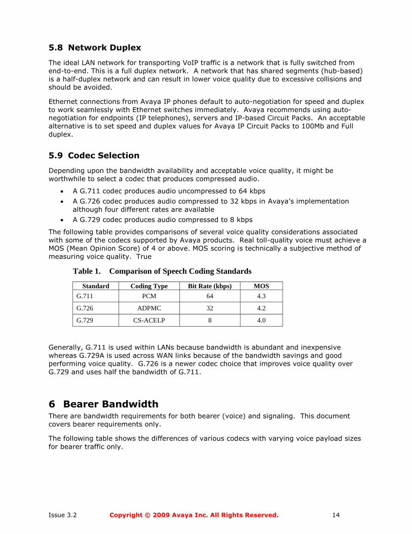
The following table provides comparisons of several voice quality considerations associated
with some of the codecs supported by Avaya products. Real toll-quality voice must achieve a
MOS (Mean Opinion Score) of 4 or above. MOS scoring is technically a subjective method of
measuring voice quality. True
Table 1. Comparison of Speech Coding Standards
Standard Coding Type Bit Rate (kbps) MOS
G.711 PCM 64 4.3
G.726 ADPMC 32 4.2
G.729 CS-ACELP 8 4.0
Generally, G.711 is used within LANs because bandwidth is abundant and inexpensive
whereas G.729A is used across WAN links because of the bandwidth savings and good
performing voice quality. G.726 is a newer codec choice that improves voice quality over
G.729 and uses half the bandwidth of G.711.
6 Bearer Bandwidth There are bandwidth requirements for both bearer (voice) and signaling. This document
covers bearer requirements only.
The following table shows the differences of various codecs with varying voice payload sizes
for bearer traffic only.
Issue 3.2 Copyright © 2009 Avaya Inc. All Rights Reserved. 15
6.1 WAN Bandwidth Comparison
Examples of Layer 2 protocols include Ethernet, Frame Relay, PPP, ATM and others. Note that
8 bytes was used for the layer-2 calculation contribution because the most used data
protocols, Frame Relay and PPP, can use 8 bytes or less.
WAN bandwidth is expensive compared to LAN bandwidth driving the need to use
compression in both voice payloads and possibly the headers of the TCP/IP protocol stack.
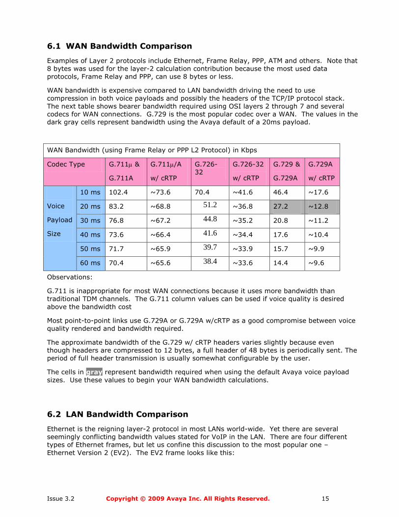
The next table shows bearer bandwidth required using OSI layers 2 through 7 and several
codecs for WAN connections. G.729 is the most popular codec over a WAN. The values in the
dark gray cells represent bandwidth using the Avaya default of a 20ms payload.
WAN Bandwidth (using Frame Relay or PPP L2 Protocol) in Kbps
Codec Type G.711 &
G.711A
G.711/A
w/ cRTP
G.726-
32
G.726-32
w/ cRTP
G.729 &
G.729A
G.729A
w/ cRTP
Voice
Payload
Size
10 ms 102.4 ~73.6 70.4 ~41.6 46.4 ~17.6
20 ms 83.2 ~68.8 51.2 ~36.8 27.2 ~12.8
30 ms 76.8 ~67.2 44.8 ~35.2 20.8 ~11.2
40 ms 73.6 ~66.4 41.6 ~34.4 17.6 ~10.4
50 ms 71.7 ~65.9 39.7 ~33.9 15.7 ~9.9
60 ms 70.4 ~65.6 38.4 ~33.6 14.4 ~9.6
Observations:
G.711 is inappropriate for most WAN connections because it uses more bandwidth than
traditional TDM channels. The G.711 column values can be used if voice quality is desired
above the bandwidth cost
Most point-to-point links use G.729A or G.729A w/cRTP as a good compromise between voice
quality rendered and bandwidth required.
The approximate bandwidth of the G.729 w/ cRTP headers varies slightly because even
though headers are compressed to 12 bytes, a full header of 48 bytes is periodically sent. The
period of full header transmission is usually somewhat configurable by the user.
The cells in gray represent bandwidth required when using the default Avaya voice payload
sizes. Use these values to begin your WAN bandwidth calculations.
6.2 LAN Bandwidth Comparison
Ethernet is the reigning layer-2 protocol in most LANs world-wide. Yet there are several
seemingly conflicting bandwidth values stated for VoIP in the LAN. There are four different
types of Ethernet frames, but let us confine this discussion to the most popular one –
Ethernet Version 2 (EV2). The EV2 frame looks like this:
Issue 3.2 Copyright © 2009 Avaya Inc. All Rights Reserved. 16
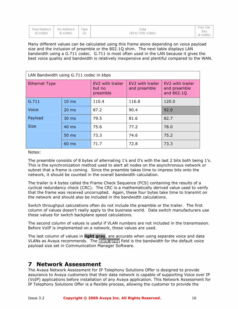
Many different values can be calculated using this frame alone depending on voice payload
size and the inclusion of preamble or the 802.1Q shim. The next table displays LAN
bandwidth using a G.711 codec. G.711 is most often used in the LAN because it gives the
best voice quality and bandwidth is relatively inexpensive and plentiful compared to the WAN.
LAN Bandwidth using G.711 codec in kbps
Ethernet Type EV2 with trailer
but no
preamble
EV2 with trailer
and preamble
EV2 with trailer
and preamble
and 802.1Q
G.711
Voice
Payload
Size
10 ms 110.4 116.8 120.0
20 ms 87.2 90.4 92.0
30 ms 79.5 81.6 82.7
40 ms 75.6 77.2 78.0
50 ms 73.3 74.6 75.2
60 ms 71.7 72.8 73.3
Notes:
The preamble consists of 8 bytes of alternating 1’s and 0’s with the last 2 bits both being 1’s.
This is the synchronization method used to alert all nodes on the asynchronous network or
subnet that a frame is coming. Since the preamble takes time to impress bits onto the
network, it should be counted in the overall bandwidth calculation.
The trailer is 4 bytes called the Frame Check Sequence (FCS) containing the results of a
cyclical redundancy check (CRC). The CRC is a mathematically derived value used to verify
that the frame was received uncorrupted. Again, these four bytes take time to transmit on
the network and should also be included in the bandwidth calculations.
Switch throughput calculations often do not include the preamble or the trailer. The first
column of values doesn’t really apply to the business world. Data switch manufacturers use
these values for switch backplane speed calculations.
The second column of values is useful if VLAN numbers are not included in the transmission.
Before VoIP is implemented on a network, these values are used.
The last column of values in light gray, are accurate when using separate voice and data
VLANs as Avaya recommends. The dark gray field is the bandwidth for the default voice
payload size set in Communication Manager Software.
7 Network Assessment The Avaya Network Assessment for IP Telephony Solutions Offer is designed to provide
assurance to Avaya customers that their data network is capable of supporting Voice over IP
(VoIP) applications before installation of any Avaya application. This Network Assessment for
IP Telephony Solutions Offer is a flexible process, allowing the customer to provide the
Issue 3.2 Copyright © 2009 Avaya Inc. All Rights Reserved. 17
required network assessment data themselves or provide the data to Avaya through their
network vendor.
The Network Assessment Services for IP Telephony Solutions consist of two distinct services.
Avaya offers these two services to help customers determine if their data networks are ready
for converged voice and data networking.
What is a BASIC?
A Basic Assessment (BASIC) is a high-level survey of a customers network. The BASIC
consists of two parts: a written survey that the end user fills out describing their voice and
data network, and a data gathering application. The application is installed on a computer in
the customers network, and runs for a period of time, usually a week. The application
discovers network devices (e.g., routers and switches) and monitors their performance.
What does a BASIC actually test?
A BASIC is a high-level test of network health. It is designed to identify gross network
problems such as oversubscribed WAN links, routing loops and overloaded devices. The
BASIC application runs from a central location, identifying network devices (i.e. discovery)
and then monitoring basic performance parameters via SNMP polling. By monitoring a router’s
interface parameters, the application can determine if the interface is oversubscribed,
dropping packets, or experiencing errors.
The data gathered is presented as a map of the customers network and a graphs outlining
device performance.
Customers who do not avail themselves of this offer assume responsibility for all network-
related problems with the IP Voice installation. Also, Avaya personnel may be required to
charge a higher T&M (Time and Materials) rate if assistance is needed, since troubleshooting
will be more difficult without the assessment data.
What is a DETAILED?
A Detailed Assessment is an in-depth assessment, designed to accurately determine a
customer’s readiness for VoIP. The DETAILED consists of two parts: the first part analyses
the network by discovering network devices and then injecting simulated VoIP traffic into the
network at selected locations. While simulating the traffic, it simultaneously measures
network device performance. The analysis not only identifies problems, it determines the
root cause of the problem so that it can be corrected.
The second part of the DETAILED, the network optimization, is a service that defines the
requirements for optimizing a network for VoIP and correcting problems found during the
assessment. It provides the customer with the steps that need to be performed in order to
make the network VoIP-ready. In addition, this service can make corrections to the
customer’s network. A variety of services can be performed including re-engineering portions
of the network, reconfiguring devices, and other actions
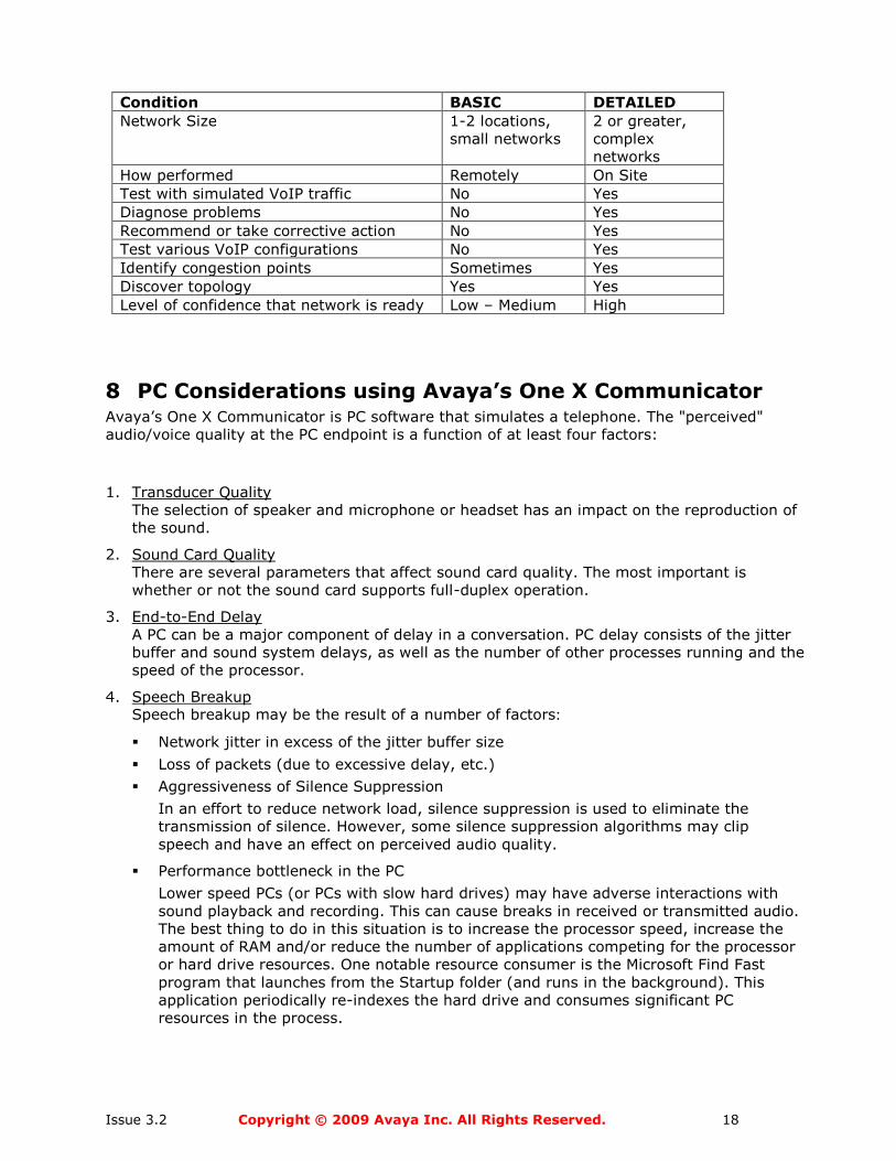
How to Choose between a BASIC and DETAILED
The following table should be used as a guide for deciding which service best meets the
customer’s requirements.
Issue 3.2 Copyright © 2009 Avaya Inc. All Rights Reserved. 18
Condition BASIC DETAILED
Network Size 1-2 locations,
small networks
2 or greater,
complex
networks
How performed Remotely On Site
Test with simulated VoIP traffic No Yes
Diagnose problems No Yes
Recommend or take corrective action No Yes
Test various VoIP configurations No Yes
Identify congestion points Sometimes Yes
Discover topology Yes Yes
Level of confidence that network is ready Low – Medium High
8 PC Considerations using Avaya’s One X Communicator Avaya’s One X Communicator is PC software that simulates a telephone. The "perceived"
audio/voice quality at the PC endpoint is a function of at least four factors:
1. Transducer Quality
The selection of speaker and microphone or headset has an impact on the reproduction of
the sound.
2. Sound Card Quality
There are several parameters that affect sound card quality. The most important is
whether or not the sound card supports full-duplex operation.
3. End-to-End Delay
A PC can be a major component of delay in a conversation. PC delay consists of the jitter
buffer and sound system delays, as well as the number of other processes running and the
speed of the processor.
4. Speech Breakup Speech breakup may be the result of a number of factors:
Network jitter in excess of the jitter buffer size
Loss of packets (due to excessive delay, etc.)
Aggressiveness of Silence Suppression
In an effort to reduce network load, silence suppression is used to eliminate the
transmission of silence. However, some silence suppression algorithms may clip
speech and have an effect on perceived audio quality.
Performance bottleneck in the PC
Lower speed PCs (or PCs with slow hard drives) may have adverse interactions with
sound playback and recording. This can cause breaks in received or transmitted audio.
The best thing to do in this situation is to increase the processor speed, increase the
amount of RAM and/or reduce the number of applications competing for the processor
or hard drive resources. One notable resource consumer is the Microsoft Find Fast
program that launches from the Startup folder (and runs in the background). This
application periodically re-indexes the hard drive and consumes significant PC
resources in the process.
Issue 3.2 Copyright © 2009 Avaya Inc. All Rights Reserved. 19
9 Bandwidth Requirements The bandwidth available to the user is very important. Access to the network using slower
connections, such as dial-up connections, will degrade voice quality. The best voice quality is
achieved in both LANs and WANs when the bandwidth is ―owned‖ by the customer.
Customer-owned bandwidth can be shaped to optimize VoIP traffic. Conversely, bandwidth
that is not controlled, like the Internet, cannot give consistent sound quality because it cannot
be optimized for VoIP. Because factors of delay, jitter, and packet loss are exacerbated over
the Internet, we do not recommend using the Internet for voice applications at this time.
9.1 Bandwidth Requirements using 1-X Communicator (or IP Agent)
A dual connect system is commonly used in a Call Center for users working remotely. The PC
and the telephone can transmit frames across the same telephone line or on two lines.
Questions concerning the amount of bandwidth the PC uses and its effect on voice are
answered here. The bandwidth used by the PC for signaling is very low. However, it is
difficult to express this value in bits per second due to the variability in how quickly the
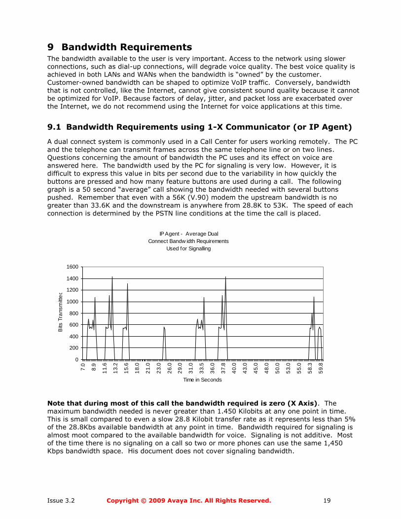
buttons are pressed and how many feature buttons are used during a call. The following
graph is a 50 second ―average‖ call showing the bandwidth needed with several buttons
pushed. Remember that even with a 56K (V.90) modem the upstream bandwidth is no
greater than 33.6K and the downstream is anywhere from 28.8K to 53K. The speed of each
connection is determined by the PSTN line conditions at the time the call is placed.
IP Agent - Average Dual
Connect Bandw idth Requirements
Used for Signalling
0
200
400
600
800
1000
1200
1400
1600
7.0
8.9
11.6
13.2
15.6
18.0
21.0
23.0
26.0
29.0
31.0
33.5
36.0
37.8
40.0
43.0
45.0
48.0
50.0
53.0
55.0
58.3
59.8
Time in Seconds
Bits
Tra
nsm
itte
d
Note that during most of this call the bandwidth required is zero (X Axis). The
maximum bandwidth needed is never greater than 1.450 Kilobits at any one point in time.
This is small compared to even a slow 28.8 Kilobit transfer rate as it represents less than 5%
of the 28.8Kbs available bandwidth at any point in time. Bandwidth required for signaling is
almost moot compared to the available bandwidth for voice. Signaling is not additive. Most
of the time there is no signaling on a call so two or more phones can use the same 1,450
Kbps bandwidth space. His document does not cover signaling bandwidth.
Issue 3.2 Copyright © 2009 Avaya Inc. All Rights Reserved. 20
10 Other Elements that Affect VoIP
10.1 WAN Considerations
Until WAN bandwidth becomes affordable at any speed, delivering bandwidth to applications
over the WAN will remain a formidable task. When voice traffic is carried on packet networks,
different labeling or queuing schemes function to give voice packets priority over data
packets. The presence of large data packets may result in added serialization delay for VoIP
packets across WAN links. This is due to the fact that smaller VoIP packets are held in queue
while larger data packets are processed onto the WAN link. To avoid excessive delay, there
may be benefit to fragmenting the larger data packets and interleaving them with the smaller
voice packets.
One technique is to adjust the packets by adjusting the Maximum Transmission Unit (MTU)
size. Minimum MTU size should be no smaller than 300 bytes and no larger than 550 bytes.
LAN based MTUs can be as large as 1500 bytes. Note: reducing the size of the MTU will add
overhead and reduce the efficiency of data applications. Other techniques, such as Multilink
PPP (MPP) Link Fragmenting and Interleaving (LFI), and Frame Relay Fragmentation (FRF12)
allow network managers to fragment larger packets, and allow queuing mechanisms to speed
the delivery of Real Time Protocol (RTP) traffic without significantly increasing protocol
overhead or reducing data efficiency. Also, header compression protocols like CRTP
(Compressed Real Time Protocol) can and should be used between WAN links. Hardware
based CRTP is effective with very minimal delays, but software CRTP can add significant
delay.
10.2 VPN (Virtual Private Network)
There are many definitions for Virtual Private Networks (VPN). In this white paper, VPNs refer
to encrypted tunnels carrying packetized data between remote sites. VPNs can use private
lines or use the Internet via one or more Internet Service Providers (ISP). VPNs are
implemented in both dedicated hardware and software, but can also be integrated as an
application to existing hardware and software packages. A common example of an integrated
package is a firewall product that can provide a barrier against unauthorized intrusion, as well
as perform the security features needed for a VPN session.
The encryption process can take from less than 1 milli-second to 1 second or more, at each
end. Obviously, VPNs can represent a significant source of delay and, therefore, negatively
affect voice performance. Also, as most VPN traffic runs over the Internet and there is little
control over QoS parameters for traffic crossing the Internet, voice quality may suffer due to
excessive packet loss, delay, and jitter. Users may be able to negotiate a service-level
agreement with the VPN provider to guarantee an acceptable level of service. Before
implementing VoIP with a VPN, users should test their VPN network to make sure it meets the
requirements specified in the Document Summary.
10.3 Frame Relay
Voice transported over frame relay can be subject to more delay and jitter when compared to
ATM or point-to-point TDM circuits. This is due to many factors, which are not covered in
detail here. Instead, Avaya offers remedies to protect voice traffic from the susceptibilities of
frame relay in Appendix B.
Issue 3.2 Copyright © 2009 Avaya Inc. All Rights Reserved. 21
10.4 Multi Protocol Label Switching (MPLS)
Voice using MPLS is an effective replacement for Frame Relay services because maintenance
and operational costs are generally lower. It is very important to choose a premium service
offering from the MPLS provider to treat voice and video with real-time delay, jitter and
packet loss needs. The SLA (Service Level Agreement) should define this service and any
penalties for lack of service. The SLA should define which DSCP values from the customer will
receive real-time treatment.
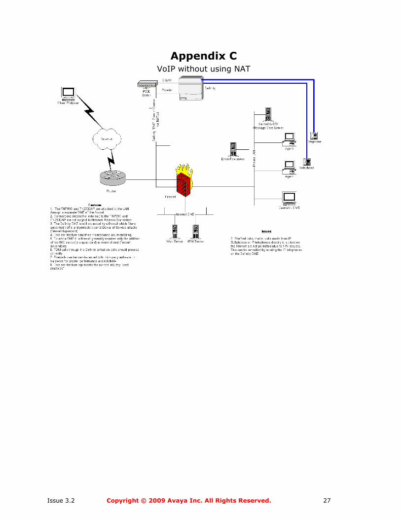
10.5 Network Address Translation (NAT)
VoIP may not work well with networks that use NAT (Network Address Translation) because
many NAT implementations do not support H.323 protocols. The destination IP address is
encapsulated in more than one header: the Q.931/H.225, and IP headers. Some NAT
implementations change only the address in the IP header resulting in a mismatch that
prohibits the control of calls. Avaya suggests using a firewall to guard against intruders, but
the firewall should not provide NAT functions for VoIP packets unless it is H.323 aware.
Appendix C shows an approved sample implementation of a firewall using selective NAT.
Issue 3.2 Copyright © 2009 Avaya Inc. All Rights Reserved. 22
Appendix A Network Design Recommendations
In the early days of Local Area Networking, network designers used hubs to attach servers
and workstations, and routers to segment the network into manageable pieces. Because of
the high cost of router interfaces and the inherent limitations of shared-media hubs, network
design was fairly simple. In recent years, with the rise of switches to segment networks,
designers could hide a number of faults in their networks and still get good performance. As a
result, network design has suffered.
VoIP will place new demands on the network. Sub-optimal designs will not be able to cope
with these demands. Even with switches installed, a company must pay attention to industry
―best practices‖ in order to have a properly functioning voice network. Because most users
will not tolerate poor voice quality, administrators should implement a sound network before
beginning VoIP pilots or deployments.
Best practices Industry best practices dictate that a network be designed with the following factors in mind:
Reliability/redundancy
Scalability
Manageability
Bandwidth
Voice mandates the following additional considerations when designing a network:
Delay
Jitter
Loss
Duplex
Generally speaking, these concerns dictate a hierarchical network consisting of at most three
layers: core, distribution, and access. Some smaller networks can collapse the functions of
several layers into one device.
The core layer is the heart of the network. Its purpose is to forward packets as quickly as
possible. It should be designed with high availability in mind. Generally, these high-
availability features include redundant devices, redundant power supplies, redundant
processors, and redundant links. In the current era, core interconnections increasingly use
Gigabit Ethernet.
The distribution layer links the access layer with the core. It is here that QoS feature and
access-lists are applied. Generally, Gigabit Ethernet connects to the core and either Gigabit
Ethernet or 100base-TX/FX links connect the access layer. Redundancy is important at this
layer, but not as important as in the core.
The access layer connects servers and workstations. Switches at this layer are smaller,
usually 24-48 ports. Desktop computers and workstations are usually connected at 10 Mbps,
(or 100Mbps) and servers are connected at 100 Mbps, (or 1 Gbps). Limited redundancy is
used. Some QoS and security features can be implemented here.
For VoIP to work well, WAN links should be properly sized with sufficient bandwidth for voice
and data traffic. Each voice call uses between 6.3 Kbps and 80 Kbps, depending on the
desired codec, quality and header compression used. G.729 is one of the most promising
standards today, using 24 Kbps of bandwidth. Interoffice bandwidth demands can be sized
Issue 3.2 Copyright © 2009 Avaya Inc. All Rights Reserved. 23
using traditional phone metrics such as average call volume, peak volume, and average call
length.
Quality of Service also becomes increasingly important with WAN circuits. In this case, Quality
of Service can be taken to mean classification and prioritization of voice traffic. Voice traffic
should be given absolute priority through the WAN, and if links are not properly sized or
queuing strategies are not properly implemented, it will become evident both with the quality
and timeliness of voice and data traffic.
There are four technologies that work well with VoIP: ATM, Frame Relay, MPLS and point-to-
point (PPP) circuits. These technologies all have good throughput, low latency, and low jitter.
ATM has the added benefit of enhanced QoS. Frame Relay, MPLS and PPP links are more
economical, but lack some of the traffic-shaping features of ATM.
Of the four technologies, Frame Relay is the most difficult WAN circuit to use with VoIP.
Congestion in Frame Relay networks can cause frame loss, which can significantly degrade
the quality of VoIP conversations. With Frame Relay, proper sizing of the CIR (committed
information rate) is critical. In a Frame Relay network, any traffic exceeding the CIR is
marked discard eligible, and will be discarded at the carrier’s option if it experiences
congestion in its switches. It is very important that voice packets not be dropped. Therefore,
CIR should be sized to average traffic usage. Usually, 25% of peak bandwidth is sufficient.
Also, Service Level Agreements (SLAs) should be established with the carrier that defines
maximum levels of delay and frame loss, and remediation should the agreed-to levels not be
met.
Network management is another important area to consider when implementing VoIP.
Because of the stringent requirements imposed by VoIP, it is critical to have an end-to-end
view of the network and ways to implement QoS policies globally. Products such as HP
OpenView Network Node Manager, Prognosis, Concord NetHealth, and MRTG will help
administrators maintain acceptable service. Should a company not have the resources to
implement and maintain network management, outsource companies may assist with this
need.
Avaya offers network assessment and redesign services, should they be necessary.
Common issues Some common ―bad habits‖ that can severely impact network performance, especially when
using VoIP include:
Using a flat, non-hierarchical network (e.g. cascading small workgroup switches
together): This technique quickly results in bottlenecks, as all traffic must flow across
the uplinks (at maximum 1Gbps) versus traversing switch fabric (up to 256 Gbps). The
greater the number of small switches (layers), the greater the number of uplinks, and
the lower the bandwidth for an individual connection. Under a network of this type,
voice performance can quickly degrade to an unacceptable level.
Multiple subnets on a VLAN: A network of this type can have issues with broadcasts,
multicasts, and routing protocol updates. It should be avoided. It can greatly impact
voice performance and complicate troubleshooting issues.
Hub-based network: Hubs in a network create some interesting challenges for
administrators. It is advisable not to link more than four 10baseT hubs or two
100baseT hubs together. Also, the collision domain, the number of ports connected by
hubs without a switch or router in between, should be kept as low as possible. Finally,
the effective (half-duplex) bandwidth available on a shared collision domain is
approximately 35% of the total bandwidth available.
Issue 3.2 Copyright © 2009 Avaya Inc. All Rights Reserved. 24
Too many access lists: Access lists slow down a router. While they are appropriate for
voice networks, care must be taken not to apply them to unnecessary interfaces.
Traffic should be modeled beforehand, and access lists applied only to the appropriate
interface in the appropriate direction, not all interfaces in all directions.
Additional concerns when implementing VoIP include:
Network Address Translation (NAT): Due to limitations in the H.323 VoIP standard,
VoIP conversations rarely work across NAT boundaries. It is important to route voice
streams around routers or firewalls running NAT or use a H.323 friendly NAT.
Virtual Private Networks (VPN): VPNs present interesting challenges to VoIP
implementations. First, the encryption used with VPNs adds significant latency to voice
streams, adversely affecting the user experience. Second, VPNs generally run over the
Internet. Because there is no control over QoS parameters for traffic crossing the
Internet, voice quality may suffer due to excessive packet loss, delay, and jitter. For
more information, please refer to Avaya’s VPN white paper.
Issue 3.2 Copyright © 2009 Avaya Inc. All Rights Reserved. 25
Appendix B
The nature of frame relay poses somewhat of a challenge for VoIP. This document presents a
frame relay overview, and then discusses an issue that affects VoIP across frame relay links.
Overview Frame relay service is composed of three elements: the physical access circuit, the frame
relay port, and the virtual circuit. The physical access circuit is typically a T1 or fractional T1
and is provided by the local exchange carrier (LEC) between the customer premise and the
nearest central office (CO). The frame relay port is the physical access into the frame relay
network – a port on the frame relay mux itself. The access circuit rate and the frame relay
port rate must match. The virtual circuit is a logical connection between frame relay ports
that can be provided by the LEC for intra-lata frame relay, or by the inter-exchange carrier
(IXC) for inter-lata frame relay. The most common virtual circuit is a permanent virtual
circuit (PVC), which is associated with a committed information rate (CIR). The PVC is
identified at each end by a separate data-link connection identifier (DLCI).
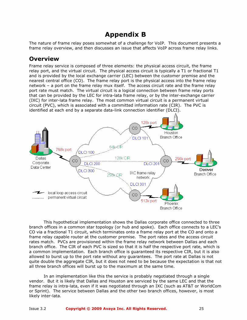
This hypothetical implementation shows the Dallas corporate office connected to three
branch offices in a common star topology (or hub and spoke). Each office connects to a LEC’s
CO via a fractional T1 circuit, which terminates onto a frame relay port at the CO and onto a
frame relay capable router at the customer premise. The port rates and the access circuit
rates match. PVCs are provisioned within the frame relay network between Dallas and each
branch office. The CIR of each PVC is sized so that it is half the respective port rate, which is
a common implementation. Each branch office is guaranteed its respective CIR, but it is also
allowed to burst up to the port rate without any guarantees. The port rate at Dallas is not
quite double the aggregate CIR, but it does not need to be because the expectation is that not
all three branch offices will burst up to the maximum at the same time.
In an implementation like this the service is probably negotiated through a single
vendor. But it is likely that Dallas and Houston are serviced by the same LEC and that the
frame relay is intra-lata, even if it was negotiated through an IXC (such as AT&T or WorldCom
or Sprint). The service between Dallas and the other two branch offices, however, is most
likely inter-lata.
Issue 3.2 Copyright © 2009 Avaya Inc. All Rights Reserved. 26
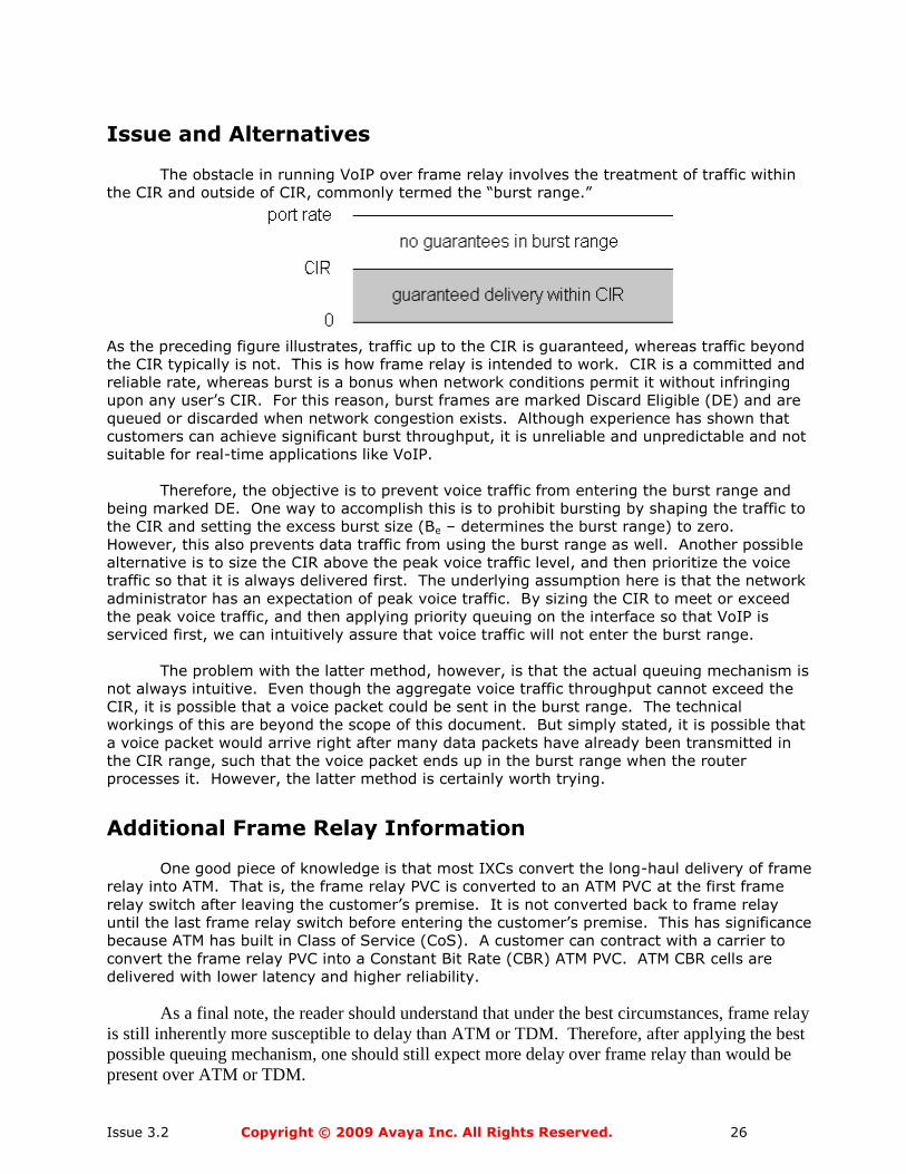
Issue and Alternatives
The obstacle in running VoIP over frame relay involves the treatment of traffic within
the CIR and outside of CIR, commonly termed the ―burst range.‖
As the preceding figure illustrates, traffic up to the CIR is guaranteed, whereas traffic beyond
the CIR typically is not. This is how frame relay is intended to work. CIR is a committed and
reliable rate, whereas burst is a bonus when network conditions permit it without infringing
upon any user’s CIR. For this reason, burst frames are marked Discard Eligible (DE) and are
queued or discarded when network congestion exists. Although experience has shown that
customers can achieve significant burst throughput, it is unreliable and unpredictable and not
suitable for real-time applications like VoIP.
Therefore, the objective is to prevent voice traffic from entering the burst range and
being marked DE. One way to accomplish this is to prohibit bursting by shaping the traffic to
the CIR and setting the excess burst size (Be – determines the burst range) to zero.
However, this also prevents data traffic from using the burst range as well. Another possible
alternative is to size the CIR above the peak voice traffic level, and then prioritize the voice
traffic so that it is always delivered first. The underlying assumption here is that the network
administrator has an expectation of peak voice traffic. By sizing the CIR to meet or exceed
the peak voice traffic, and then applying priority queuing on the interface so that VoIP is
serviced first, we can intuitively assure that voice traffic will not enter the burst range.
The problem with the latter method, however, is that the actual queuing mechanism is
not always intuitive. Even though the aggregate voice traffic throughput cannot exceed the
CIR, it is possible that a voice packet could be sent in the burst range. The technical
workings of this are beyond the scope of this document. But simply stated, it is possible that
a voice packet would arrive right after many data packets have already been transmitted in
the CIR range, such that the voice packet ends up in the burst range when the router
processes it. However, the latter method is certainly worth trying.
Additional Frame Relay Information
One good piece of knowledge is that most IXCs convert the long-haul delivery of frame
relay into ATM. That is, the frame relay PVC is converted to an ATM PVC at the first frame
relay switch after leaving the customer’s premise. It is not converted back to frame relay
until the last frame relay switch before entering the customer’s premise. This has significance
because ATM has built in Class of Service (CoS). A customer can contract with a carrier to
convert the frame relay PVC into a Constant Bit Rate (CBR) ATM PVC. ATM CBR cells are
delivered with lower latency and higher reliability.
As a final note, the reader should understand that under the best circumstances, frame relay
is still inherently more susceptible to delay than ATM or TDM. Therefore, after applying the best
possible queuing mechanism, one should still expect more delay over frame relay than would be
present over ATM or TDM.
Issue 3.2 Copyright © 2009 Avaya Inc. All Rights Reserved. 27
Appendix C VoIP without using NAT
Issue 3.2 Copyright © 2009 Avaya Inc. All Rights Reserved. 28
History
Issue 3.0 Added bandwidth tables for all supported codecs and all payload options.
Issue 3.1 Changed bandwidth tables to add G.726 codec.
Removed descriptions of general server and gateway offerings
Issue 3.2 Added general updates, inclusion of MPLS as a WAN transport and the use of
Auto-negotiation as a best practice for servers and IP-based Circuit packs.