Rev date: 09/19/2012 Innovation Voice Mail PBX Programming, Installation and Testing Guide Avaya Mode Code Integration using Dialogic Media Gateways 1841 Bourbon Road Cross Plains, Wisconsin 1-800-424-6757 www.innovationtw.com
Transcript
Rev date: 09/19/2012
Innovation Voice Mail PBX Programming, Installation and Testing Guide
Avaya Mode Code Integration using Dialogic Media Gateways
1841 Bourbon Road
Cross Plains, Wisconsin 1-800-424-6757
www.innovationtw.com
Innovation Voice Mail PBX Programming, Installation and Testing Guide
1
Avaya Mode Code Integration using DMG (Dialogic Media Gateways) REQUIREMENTS: ♦ Release 6.0 or higher ♦ An analog extension (configured as type “VMI”) for each voicemail port 1 ♦ An analog extension (or dedicated CO line) for the system’s modem. ♦ “Mode Code Interface?” on the system-parameters customer-option set to “y” 2 ♦ One Dialogic DMG1008LSW gateway for every 8 analog ports. 1Release 6.0 through 6.2 requires a TN746B circuit pack for VMI extensions. Release 6.3 and above may use any analog circuit pack for VMI extensions. 2 Avaya may need to enable this option.
PBX PROGRAMMING: 1. Create the new voicemail extensions for InnLine IP using the command add station Type: must be VMI (not 2500)
Adjunct Supervision? Must be a “y” for each VMI station. This setting provides quick disconnect supervision to InnLine IP’s voice ports.
Innovation Voice Mail PBX Programming, Installation and Testing Guide
2
Create a hunt group for the VMI extensions using the command add hunt-group
Group Extension: The number used to access the VMI extension members Group Type: Recommended setting is ddc (terminal hunt)
The example above depicts a hunt-group setup for a eight port voicemail system, VMI extensions 1901 through 1908. VMI extension 1908 will the out-dial port, turning messages lights on and off, and possibly performing other out-dial functions. It is highly recommended to not include any VMI extensions that are programmed as out-dial ports to the hunt group. This eliminates the possibility of glare occurring.
Innovation Voice Mail PBX Programming, Installation and Testing Guide
3
1. Next, type the command change system-parameters mode-code
VMS Hunt Group Extension: This is the group extension of the hunt-group created for the VMI extensions. MODE CODES (FROM SWITCH TO VMS) Values assigned to these four fields are default. Do not change them. 2. Verify what your message waiting codes are by typing the command display feature-
access-codes
The above codes are an example only, and may be different in your Avaya PBX. If codes are not assigned to the above features, use the change feature-access-codes command to program them. See “MWI dial-strings” locate in the Index of the InnLine IP Installation guide on how to program these codes into the InnLine IP system
Innovation Voice Mail PBX Programming, Installation and Testing Guide
4
3. Create a coverage path for the guest and staff extensions that will be using voicemail. You may want to create separate coverage paths (one for guests, and another for staff) if you want the guest extensions to have a slightly longer “ring-no-answer” time, before covering the caller the VMI hunt group. To add a new coverage path, use the command add coverage path
Point1: To cover callers to the VMI hunt group, you need to know what number hunt group you created. The above example shows that callers will cover to h4 (hunt group #4) 4. Cover all guest and selected staff extensions to the coverage path you just created, using the
command change station
Innovation Voice Mail PBX Programming, Installation and Testing Guide
5
NETWORK CONNECTIONS: INSTALLATIONS WITH ONE GATEWAY (8 ports or less) On the back of the InnLine IP voicemail system, connect a network cable from the top left hand corner network jack, and connect it directly to the LAN network connector on the DMG1008LSW media gateway. The IP addresses for each device are ITW default settings. InnLine IP Voicemail (rear view)
(192.168.210.2) Dialogic Media Gateway (rear view)
(Avaya VMI analog stations 1 – 8) / (192.168.210.10)
Innovation Voice Mail PBX Programming, Installation and Testing Guide
6
INSTALLATIONS WITH MULTIPLE GATEWAYS (more than 8 ports) Connect a network cable from the top left hand corner network jack, and connect it to the jack labeled #5 of the NETGEAR switch. Then connect another network cable from the jack labeled #1 on the NETGEAR switch to the LAN network jack on the Dialogic DMG1008LSW media gateway. Repeat the connections from the NETGEAR switch (#2 through #4) for connecting your additional media gateways. The example below shows connectivity for a 32 port system. The IP addresses for each device are ITW default settings.
(192.168.210.2)
(Avaya VMI analog stations 1 – 8) / (192.168.210.10)
(Avaya VMI analog stations 9 – 16) / (192.168.210.11)
(Avaya VMI analog stations 17 – 24) / (192.168.210.12)
(Avaya VMI analog stations 25 – 32) / (192.168.210.13)
Innovation Voice Mail PBX Programming, Installation and Testing Guide
7
PBX TERMINATIONS: The Dialogic DMG1008LSW has 8 RJ14 style connectors on the back. Connect the Avaya VMI analog stations to the gateway’s RJ14 jacks numbered 1 through 8 using standard line cords.
As you connect each line cord, the Port Status led indicator for that line will change from red to green. This indicates that Carrier is present.
Port Status definitions:
• Steady Green – indicates that Carrier is present. • Flashing Green – indicates that there is activity on the port. • Steady Yellow – Hardware Carrier is present, but no software communication. • Flashing Yellow – External power detected, but port cannot gain carrier • Steady Red – Indicates that no Carrier is present and no external power detected
Innovation Voice Mail PBX Programming, Installation and Testing Guide
8
VOICEMAIL PROGRAMMING:
InnLine IP Configuration Utility (IIPConfig) On the desktop, open the file InnLine IP Config and review the following information:
Local IP Address: This field displays the static IP Address assigned to the InnLine IP voicemail. SIP Proxy Address: This is the IP Address of the first Dialogic Media Gateway. The default value is 192.168.210.10. In a multiple gateway installation, it is the IP address of the last gateway. SIP Password: This is the password that is programmed for each Avaya VMI analog station that is connected to the media gateway(s). Authentication Realm: This is the realm name that is referenced for each of the Avaya VMI analog stations that are connected to the media gateway(s) If you have changed anything, click Save, then Cancel to exit. In order for these changes to take, you must stop InnLine IP application, and then re-start it (by double-clicking the InnLine IP icon located on the desktop.
Innovation Voice Mail PBX Programming, Installation and Testing Guide
9
Voice Port Configuration – single gateway Go to Do > Configure System > Voice Ports and double the Port Wizard (choose Yes to run the port wizard at this time
If your Avaya VMI analog stations are concurrent, enter the first number in BOTH the 1st Extension and Sip Alias fields. Click OK. The port wizard will now automatically populate these fields in the other Port Screens IMPORTANT NOTE: The last port is always set to Out-Bound only. This port needs to be protected from inbound calls. Put that Avaya VMI analog station into DND. If you require additional ports to perform outbound events, then these Avaya VMI analog stations need to be put into DND as well.
Innovation Voice Mail PBX Programming, Installation and Testing Guide
10
Voice Port Configuration – multiple gateways If your installation has more than one gateway, you will need to enable and configure the Port Outbound Proxy settings. The example below shows a 3 gateway setup, using the port wizard: Ports 1-8 (701-708) will use IP address 192.168.210.10 Ports 9-16 (709-716) will use IP address 192.168.210.11 Ports 17-24 (717-724) will use IP address 192.168.210.12 Ports1 - 8
Avaya VMI stations 1901 through 1908 (note the Starting Port and Ending Port numbers in the wizard port range are 1 through 8…also note that the host name is 192.168.210.10)
Innovation Voice Mail PBX Programming, Installation and Testing Guide
11
Ports 9 - 16
Avaya VMI stations 1909 through 1916 (note the Starting Port and Ending Port numbers in the wizard port range are 9 through 16…also note that the host name is 192.168.210.11)
Innovation Voice Mail PBX Programming, Installation and Testing Guide
12
Ports 17-24
ONS stations 717 through 724 (note the Starting Port and Ending Port numbers in the wizard port range are 17 through 24…also note that the Port Outbound Proxy does not need to be enabled). The IP address 192.168.210.12 of the third gateway will be referenced in the IIP Config utlity’s SIP Proxy Address field:
Innovation Voice Mail PBX Programming, Installation and Testing Guide
13
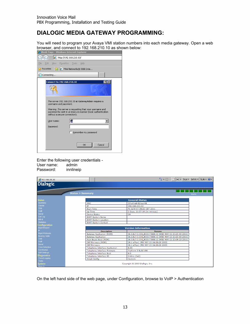
DIALOGIC MEDIA GATEWAY PROGRAMMING: You will need to program your Avaya VMI station numbers into each media gateway. Open a web browser, and connect to 192.168.210.10 as shown below:
Enter the following user credentials - User name: admin Password: innlineip
On the left hand side of the web page, under Configuration, browse to VoIP > Authentication
Innovation Voice Mail PBX Programming, Installation and Testing Guide
14
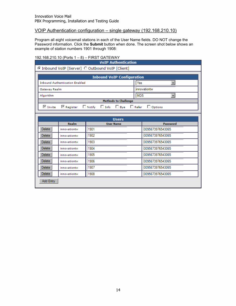
VOIP Authentication configuration – single gateway (192.168.210.10) Program all eight voicemail stations in each of the User Name fields. DO NOT change the Password information. Click the Submit button when done. The screen shot below shows an example of station numbers 1901 through 1908: 192.168.210.10 (Ports 1 – 8) – FIRST GATEWAY
Innovation Voice Mail PBX Programming, Installation and Testing Guide
15
VOIP Authentication configuration – multiple gateways If you have a second gateway, the next eight station numbers (example shown is 1909 through 1916) will be programmed into the 192.168.210.11 gateway. If you have a third, the next eight station numbers (example shown is 1917 through 1924) are programmed into the 192.168.210.12 gateway. Use this numbering scheme for additional gateways. 192.168.210.11 (Ports 9 – 16) – SECOND GATEWAY
Innovation Voice Mail PBX Programming, Installation and Testing Guide
16
192.168.210.12 (Ports 17 – 24) – THIRD GATEWAY
Innovation Voice Mail PBX Programming, Installation and Testing Guide
17
TESTING Testing disconnect supervision When a caller is connected to voicemail and hangs up, the Avaya PBX will provide a momentary open. This is the voicemail systems indication to disconnect. Test this by placing a call from any station to the voicemail system. After voicemail answers, hang up. On the gateway, look at the line that the call came in on. If the green led stops flashing, returning to steady green within a few seconds after hanging up, then disconnect supervision is working properly. Call each of the remaining voicemail stations, (hanging up after each port answers) and watch to see if the gateway led goes from flashing green to steady green. This test should be performed station to station and trunk to station. For a trunk to station test, call the hotel’s main number, and have the attendant transfer you to voicemail. When voicemail answers, hang-up and watch the gateways led status as described above. If disconnect supervision does not work, make sure that Adjunct Supervision (on page 2 of the add / change station form) set to a “y”. Testing direct calls (From any station) From any station (guest or staff), place a call to the hunt-group access code is programmed for voicemail. The activity window will show what station number is calling. (Example below shows staff extension 350 calling the voicemail hunt-group access code) 001 << DIRECT CALL FROM 350 >> 001 play 513 001 wait for call... Testing the call coverage Apply the coverage path number you created for voicemail users to either a guest or staff extension. This is accomplished by using the change station command. Program the voicemail coverage path for this station under the Coverage Path 1 field. Ring the station you are testing, allowing the call to cover to voicemail. The following example is of station 350 calling station 102: 003 << FORWARDED CALL FROM 102 DIALED BY 350 >> 003 play GUNA 003 play 1631 1634 003 wait for call... Perform this forwarding test via a trunk as well
Innovation Voice Mail PBX Programming, Installation and Testing Guide
18
Testing message lamps Test a message lamp by going to System >Tenants >Tenant 1 > Mailboxes. Double click the Set MWI(s) icon.
Enter a valid extension number and test turning the message lamp on and off. The voicemail will transmit the light on / off commands using the Leave Word Calling Send a Message / Cancel a Message codes you programmed under the InnLine IP port type. END OF DOCUMENT