268
OPERATOR’S MANUAL B-63494EN/01
OPERATOR’S MANUAL
B-63494EN/01

No part of this manual may be reproduced in any form.
All specifications and designs are subject to change without notice.
In this manual we have tried as much as possible to describe all thevarious matters.However, we cannot describe all the matters which must not be done,or which cannot be done, because there are so many possibilities.Therefore, matters which are not especially described as possible inthis manual should be regarded as ”impossible”.
B-63494EN/01 SAFETY PRECAUTIONS
s-1
SAFETY PRECAUTIONSThis manual includes safety precautions for protecting the user andpreventing damage to the machine. Precautions are classified intoWarning and Caution according to their bearing on safety. Also,supplementary information is described as a Note. Read the Warning,Caution, and Note thoroughly before attempting to use the machine.
WARNINGApplied when there is a danger of the user beinginjured or when there is a damage of both the userbeing injured and the equipment being damaged ifthe approved procedure is not observed.
CAUTIONApplied when there is a danger of the equipmentbeing damaged, if the approved procedure is notobserved.
NOTEThe Note is used to indicate supplementaryinformation other than Warning and Caution.
- Read this manual carefully, and store it in a safe place.

B-63494EN/01 TABLE OF CONTENTS
c-1
TABLE OF CONTENTS
SAFETY PRECAUTIONSSAFETY PRECAUTIONSSAFETY PRECAUTIONSSAFETY PRECAUTIONS............................................................................................................................................................................................................................................................................................................................................................................................................................................................................................ s-s-s-s-1111
1111 OVERVIOVERVIOVERVIOVERVIEWEWEWEW.................................................................................................................................................................................................................................................................................................................................................................................................................................................................................................................................................................... 1111
1.1 DIRECTIVE AND STANDARDS ..................................................................................................... 3
1.1.1 Directives.................................................................................................................................... 3
1.1.2 Related Safety Standards.......................................................................................................... 3
1.1.3 Risk Analysis and Evaluation................................................................................................... 3
1.1.4 Certification Test ....................................................................................................................... 4
1.2 DEFINITION OF TERMS ................................................................................................................ 5
1.2.1 General Definition of Terms ..................................................................................................... 5
1.2.2 Definition of Terms Related to the Safety Function................................................................ 5
1.3 BASIC PRINCIPLE OF DUAL CHECK SAFETY .......................................................................... 6
1.3.1 Features of Dual Check Safety ................................................................................................. 6
1.3.2 Compliance with the Safety Standard (EN954-1, Category 3) ............................................... 7
1.3.2.1 Latent error detection and cross-check ...........................................................................................8
1.3.2.2 Safety monitoring cycle and cross-check cycle ................................................................................9
1.3.2.3 MCC off Test .....................................................................................................................................9
1.3.2.4 Error analysis .................................................................................................................................10
1.3.2.5 Remaining risks..............................................................................................................................10
1.4 GENERAL INFORMATION........................................................................................................... 12
2222 SYSTEM CONFIGURATIOSYSTEM CONFIGURATIOSYSTEM CONFIGURATIOSYSTEM CONFIGURATIONNNN............................................................................................................................................................................................................................................................................................................................................................................................................................................ 14141414
3333 SAFETY FUNCTIONSSAFETY FUNCTIONSSAFETY FUNCTIONSSAFETY FUNCTIONS .................................................................................................................................................................................................................................................................................................................................................................................................................................................................................... 16161616
3.1 APPLICATION RANGE ................................................................................................................. 17
3.2 BEFORE USING THE SAFETY FUNCTION............................................................................... 20
3.2.1 Important Items to Check Before Using the Safety Function .............................................. 20
3.2.2 MCC off Test of the Safe Stop Function ................................................................................. 20
3.3 STOP ................................................................................................................................................ 21
3.3.1 Stopping the Spindle Motor .................................................................................................... 21
3.3.2 Stopping the Servo Motor........................................................................................................ 22
3.3.3 Stop States ............................................................................................................................... 22
3.4 SAFE-RELATED I/O SIGNAL MONITORING ............................................................................ 24
3.5 EMERGENCY STOP ...................................................................................................................... 29
3.6 SAFE SPEED MONITORING........................................................................................................ 30
3.7 SAFE MACHINE POSITION MONITORING .............................................................................. 31

TABLE OF CONTENTS B-63494EN/01
c-2
3.8 MCC OFF TEST .............................................................................................................................. 32
4444 INSTALLATIOINSTALLATIOINSTALLATIOINSTALLATIONNNN............................................................................................................................................................................................................................................................................................................................................................................................................................................................................................................................ 33333333
4.1 OVERALL CONNECTION DIAGRAM ......................................................................................... 35
4.1.1 For One-path............................................................................................................................ 35
4.1.2 For Two-path............................................................................................................................ 37
4.2 DI/DO CONNECTION (VIA THE PMC) ....................................................................................... 40
4.3 DI/DO CONNECTION (VIA THE FSSB) ...................................................................................... 41
4.3.1 FSSB I/O Connection............................................................................................................... 41
4.3.2 FSSB I/O Attachment.............................................................................................................. 43
4.3.3 FSSB I/O Specification List..................................................................................................... 47
5555 I/OI/OI/OI/O SIGNALS SIGNALS SIGNALS SIGNALS ................................................................................................................................................................................................................................................................................................................................................................................................................................................................................................................................................ 48484848
5.1 OVERVIEW ..................................................................................................................................... 49
5.2 SIGNALS ......................................................................................................................................... 50
5.3 SIGNAL ADDRESSES.................................................................................................................... 55
5.4 SAFETY SIGNAL MODES............................................................................................................. 56
5.5 NOTES ON MULTI-PATH CONTROL ......................................................................................... 57
5.5.1 Two-CPU Two-Path Control (Without Axis Change between Paths)................................... 57
5.5.2 Two-CPU Two-Path Control (With Axis Change between Paths) ........................................ 58
5.5.3 One-CPU Two-Path Control.................................................................................................... 59
5.5.4 Two-CPU Three-Path Control................................................................................................. 60
5.5.5 Loader Control ......................................................................................................................... 61
6666 PARAMETERSPARAMETERSPARAMETERSPARAMETERS .................................................................................................................................................................................................................................................................................................................................................................................................................................................................................................................................... 62626262
6.1 OVERVIEW ..................................................................................................................................... 63
6.2 PARAMETERS................................................................................................................................ 64
6.3 PARAMETERS RELATED TO THE USE OF FSSB I/O UNIT ................................................... 72
6.4 FUNCTIONS THAT REQUIRE SPECIAL PARAMETER SETTINGS....................................... 74
6.4.1 Tandem Control ....................................................................................................................... 74
6.4.2 Simple Electronic Gear Box and Electronic Gear Box 2-pair ............................................... 74
6.4.3 Multi-path Control................................................................................................................... 74
7777 START-UPSTART-UPSTART-UPSTART-UP ................................................................................................................................................................................................................................................................................................................................................................................................................................................................................................................................................................ 75757575
7.1 START-UP OPERATION................................................................................................................ 76
7.1.1 Acceptance Test and Report for Safety Functions................................................................. 76
7.1.2 Start-up of the Dual Check Safety Function.......................................................................... 78
7.1.2.1 Initial start-up ................................................................................................................................78

B-63494EN/01 TABLE OF CONTENTS
c-3
7.1.2.2 Series start-up ................................................................................................................................80
7.1.3 Troubleshooting ....................................................................................................................... 80
8888 MAINTENANCEMAINTENANCEMAINTENANCEMAINTENANCE ........................................................................................................................................................................................................................................................................................................................................................................................................................................................................................................................ 81818181
8.1 SAFETY PRECAUTIONS............................................................................................................... 82
8.2 ALARMS AND MESSAGES........................................................................................................... 86
8.2.1 Overview................................................................................................................................... 86
8.2.2 Servo Alarms............................................................................................................................ 87
8.2.3 Serial Spindle Alarms.............................................................................................................. 91
8.2.4 Alarms Displayed on the Spindle Unit................................................................................... 92
8.2.5 System Alarms......................................................................................................................... 93
8.2.6 Boot System Alarms ................................................................................................................ 93
9999 DIAGNOSISDIAGNOSISDIAGNOSISDIAGNOSIS........................................................................................................................................................................................................................................................................................................................................................................................................................................................................................................................................................ 94949494
9.1 OVERVIEW ..................................................................................................................................... 95
9.2 DIAGNOSIS..................................................................................................................................... 96
10101010 SAMPLE SYSTEM CONFISAMPLE SYSTEM CONFISAMPLE SYSTEM CONFISAMPLE SYSTEM CONFIGURATIONGURATIONGURATIONGURATION............................................................................................................................................................................................................................................................................................................................................................ 97979797
10.1 SAMPLE CONFIGURATION......................................................................................................... 98
10.1.1 For One-path............................................................................................................................ 98
10.1.2 For Two-path (When the main side and sub side use a common MCC)............................... 99
10.1.3 For Two-path (When the main side and sub side use independent MCCs and
protection doors) .................................................................................................................... 100
10.2 SAMPLE CONNECTIONS........................................................................................................... 101
10.2.1 Emergency Stop Signal (*ESP1, *ESP2).............................................................................. 101
10.2.2 Guard Open Request Signal (ORQ)...................................................................................... 102
10.2.3 Test Mode Signal (OPT) ........................................................................................................ 102
10.2.4 Guard Unlock Signal (*LGD), Guard Lock State Signal (GDL),
Guard State Signal (SGD)..................................................................................................... 103
10.2.5 MCC On Enable Signal (MCF), MCC Contact State Signal (*SMC).................................. 105
11111111 COMPONENTS LISTCOMPONENTS LISTCOMPONENTS LISTCOMPONENTS LIST .................................................................................................................................................................................................................................................................................................................................................................................................................................................................... 106106106106
11.1 HARDWARE COMPONENTS ..................................................................................................... 107
11.1.1 Hardware Components for Series 16i/18i/21i/160i/180i/210i/160is/180is/210is-MODEL A107
11.1.2 Hardware Components for Series 16i/18i/21i/160i/180i/210i/160is/180is/210is-MODEL B107
11.1.3 Hardware Components for Other Units............................................................................... 108
11.2 SOFTWARE COMPONENTS....................................................................................................... 109
11.3 SERVO AMPLIFIER..................................................................................................................... 111

B-63494EN/01 1.OVERVIEW
- 1 -
1 OVERVIEWSetup for machining, which includes attaching and detaching aworkpiece to be machined, and moving it to the machining start pointwhile viewing it, is performed with the protection door opened. Thedual check safety function provides a means for ensuring a high levelof safety with the protection door opened.
The simplest method of ensuring safety when the protection door isopen is to shut off power to the motor drive circuit by configuring asafety circuit with a safety relay module. In this case, however, nomovements can be made on a move axis (rotation axis). Moreover,since the power is shut off, some time is required before machiningcan be restarted. This drawback can be corrected by adding a motorspeed detector to ensure safety. However, the addition of an externaldetector may pose a response problem, and the use of many safetyrelay modules results in a large and complicated power magneticscabinet circuit.
With the dual check safety function, two independent CPUs built intothe CNC monitor the speed and position of motors in dual mode. Anerror in speed and position is detected at high speed, and power to themotor is shut off via two independent paths. Processing and datarelated to safety is cross-checked by two CPUs. To prevent failuresfrom being built up, a safety-related hardware and software test mustbe conducted at certain intervals time.
The dual check safety function need not have an external detectoradded. Instead, only a detector built into a servo motor or spindlemotor is used. This configuration can be implemented only whenthose motors, detectors built into motors, and amplifiers that arespecified by FANUC are used. When an abnormality related to safetyoccurs, the dual check safety function stops operation safely.
The dual check safety function ensures safety with the power turnedon, so that an operator can open the protection door to work withoutturning off the power. A major feature of the dual check safetyfunction is a very short time required from the detection of anabnormality until the power is shut off. A cost advantage of the dualcheck safety function is that external detectors and safety relays canbe eliminated or simplified.

1.OVERVIEW B-63494EN/01
- 2 -
The dual check safety function consists of the following threefunctions:- Safe-related I/O signal monitoring function- Safe speed monitoring function- Safe machine position monitoring function
The safety function operates regardless of the NC mode. Usually, thisfunction should be used in the setup mode. If a position or speedmismatch is detected by a cross-check using two CPUs, power is shutoff (MCC off) to the motor drive circuit.
The European standard certification organization has certified thatthis safety function satisfies the European Safety Standard EN954-1Category 3.
IMPORTANTThe dual check safety function cannot monitor thestop state. For details, see the example of systemconfiguration.
B-63494EN/01 1.OVERVIEW
- 3 -
1.1 DIRECTIVE AND STANDARDS
1.1.1 Directives
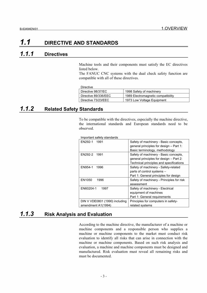
Machine tools and their components must satisfy the EC directiveslisted below.The FANUC CNC systems with the dual check safety function arecompatible with all of these directives.
DirectiveDirective 98/37/EC 1998 Safety of machineryDirective 89/336/EEC 1989 Electromagnetic compatibilityDirective 73/23/EEC 1973 Low Voltage Equipment
1.1.2 Related Safety Standards
To be compatible with the directives, especially the machine directive,the international standards and European standards need to beobserved.
Important safety standardsEN292-1 1991 Safety of machinery - Basic concepts,
general principles for design – Part 1:Basic terminology, methodology
EN292-2 1991 Safety of machinery - Basic concepts,general principles for design – Part 2:Technical principles and specifications
EN954-1 1996 Safety of machinery - Safety-relatedparts of control systems –Part 1: General principles for design
EN1050 1996 Safety of machinery - Principles for riskassessment
EN60204-1 1997 Safety of machinery - Electricalequipment of machinesPart 1: General requirements
DIN V VDE0801 (1990) includingamendment A1(1994)
Principles for computers in safety-related systems
1.1.3 Risk Analysis and Evaluation
According to the machine directive, the manufacturer of a machine ormachine components and a responsible person who supplies amachine or machine components to the market must conduct riskevaluation to identify all risks that can arise in connection with themachine or machine components. Based on such risk analysis andevaluation, a machine and machine components must be designed andmanufactured. Risk evaluation must reveal all remaining risks andmust be documented.

1.OVERVIEW B-63494EN/01
- 4 -
1.1.4 Certification Test
Certification of the dual check safety functionThe German certification organization TUV PS has certified that thedual check safety function satisfies EN954-1 Category 3.

B-63494EN/01 1.OVERVIEW
- 5 -
1.2 DEFINITION OF TERMS
1.2.1 General Definition of Terms
Reliability and safetyReliability and safety are defined by EN292-1 as follows:
Term DefinitionReliability Capability of a machine, machine component, or
equipment to perform its required function under aspecified condition for a specified period
Safety Capability of a machine to perform its function withoutinjuring the health under a condition of use for an intendedpurpose specified in the operator's manual and allow itstransportation, installation, adjustment, maintenance,disassembly, and disposal
1.2.2 Definition of Terms Related to the Safety Function
Safe-related I/O signalSafe-related I/O signals are input/output signals monitored by twosystems. These signals are valid for each feed axis and spindle with abuilt-in safety function, and are used with each monitoring system.Example: Protection door state signal
Safe stopWhen a safe stop occurs, power to the drive section is shut off. Thedrive section can generate neither a torque nor dangerous operation.The following are measures for incorporating the safe stop feature:Contactor between the line and drive system (line contactor)Contactor between the power section and drive motor (motorcontactor)If an external force is applied (such as a force applied onto a verticalaxis), an additional measure (such as a mechanical brake) must besecurely implemented to protect against such a force.
Safe speedFeature for preventing the drive section from exceeding a specifiedspeed. A measure must be implemented to prevent a set limitationspeed from being changed by an unauthorized person.
Safe machine positionWhen the drive system has reached a specified positional limit, atransition is made to the safe stop state. When a positional limit is set,a maximum move distance traveled until a stop occurs must beconsidered. A measure must be implemented to prevent a setpositional limit from being changed by an unauthorized person.

1.OVERVIEW B-63494EN/01
- 6 -
1.3 BASIC PRINCIPLE OF DUAL CHECK SAFETY
1.3.1 Features of Dual Check Safety
- Two-channel configuration with two or more independent CPUs- Cross-check function for detecting latent errors
DetectionA servo motor detector signal is sent via the servo amplifier and isapplied to the CNC through the FSB interface. Then, it is fed to twoCPUs: a CNC CPU and a monitor CPU.A spindle motor detector signal is sent via the spindle amplifier and isapplied to the CNC connected through the serial interface. Then, it isfed to two CPUs: a CNC CPU and a CPU built into the spindleamplifier.
EvaluationThe safety function is monitored independently by a CNC CPU andmonitor CPU or by a CNC CPU and spindle CPU. Each CPU cross-checks data and results at certain intervals.
ResponseIf the monitoring function detects an error, the CNC CPU and monitorCPU switch off the MCC via independent paths to shut off the powerto the feed axis and spindle.

B-63494EN/01 1.OVERVIEW
- 7 -
1.3.2 Compliance with the Safety Standard (EN954-1, Category 3)
The dual check safety function satisfies the requirements of Category3 of the safety standard EN954-1.
Category 3 requires the following: • The safety function of a safety-related portion must not degrade
when a single failure occurs. • Single errors must be detected at all times when natural
execution is possible.
To satisfy these requirements, the dual check safety function isimplemented using the two-channel configuration shown below.
Monitoring of servo motor and spindle motor movement
CNCCPU
CNCCPU
MonitorCPU
MonitorCPU
Motor detector signalDoor switch signal
Magneticcontactor
Shut off power
Shut off power
CNC controller
Cross-checkof data andresults
Data output from the detector built into each motor is transferred tothe CNC through the amplifier. The safety of this path is ensured byusing motors and amplifiers specified by FANUC.
Cross-monitoring using 2 CPUsTwo CPUs built into the CNC are used to cross-monitor the safetyfunction. Each CPU is periodically checked for errors. If one systemfails, the servo system and spindle can be stopped safely.
Power shutoff via two pathsIf an error is detected, the power is shut off via two power shutoffpaths. The paths need to be tested for built-up failures within a certaintime.
Input signal safetySafety-related input signals such as the protection door lock/unlocksignal is monitored doubly. If a mismatch between the twooccurrences of a signal is detected, the power to the motor drivecircuit is shut off. This cross-check is constantly made.

1.OVERVIEW B-63494EN/01
- 8 -
Output signal safetyA signal is output (via two paths) to the relay used to shut off thepower to the motor drive circuit. An error is detected by a MCC offTest. For detection of built-up failures, a MCC off Test needs to beconducted at certain intervals. This MCC off Test is not mandatorywhen machining is performed with the protection door closed.
1.3.2.1 Latent error detection and cross-check
Detection of latent errorsThis detection function can detect latent software and hardware errorsin a system that has a two-channel configuration. So, the safety-related portions of the two channels need to be tested at least oncewithin an allowable period of time for latent errors.An error in one monitoring channel causes a mismatch of results, sothat a cross-check detects the error.
CAUTIONForced detection of a latent error on the MCC shutoffpath must be performed by the user through a MCCoff Test (after power-on and at intervals of aspecified time (within 24 hours)).When the system is operating in the automatic mode(when the protection door is closed), this detectionprocessing is not requested as mandatory.
Cross-checkA latent safety-related error associated with two-channel monitoringcan be detected as a result of cross-checking.For numeric data, an allowable difference between the two channelsis set in a parameter. (For example, an allowable cross-checkeddifference is set for the actual position.)
NOTEAn error detected as the result of forced latent errordetection or cross-checking leads to a safety stopstate. (See Chapter ?.).

B-63494EN/01 1.OVERVIEW
- 9 -
1.3.2.2 Safety monitoring cycle and cross-check cycle
The safety function is subject to periodical monitoring in a monitoringcycle.Monitoring cycle: 16 ms
The cross-check cycle represents a cycle at which all data subject tocross-checking is compared.Cross-check cycle: 16 ms
1.3.2.3 MCC off Test
The MCC is shut off using two CPUs: a CNC CPU and monitor CPU.To detect a latent error in the MCC shutoff paths forcibly, a MCC offTest is conducted. This test is essential to dual check safety. A MCCoff Test must be conducted at specified times (after power-on and atintervals of 24 hours) to check that the MCC shutoff paths operatenormally. A MCC off Test is conducted once on the CNC side andonce on the monitor side. When a MCC off Test becomes necessary,the CNC outputs a MCC off Test execution request signal to thePMC.
NOTEThe machine tool builder is to warn and prompt theoperator to conduct a MCC off Test when a MCC offTest execution request signal is output. A MCC offTest is executed by turning on the test mode signal.
MCC off Test execution condition• All axes and the spindle must be stopped beforehand.• All vertical axes must be secured firmly beforehand.
Select-test terminationWhen a MCC off Test is completed, the MCC off Test executionrequest signal is turned off. After the MCC off Test execution requestsignal is turned off, turn off the test mode signal.
1.OVERVIEW B-63494EN/01
- 10 -
1.3.2.4 Error analysis
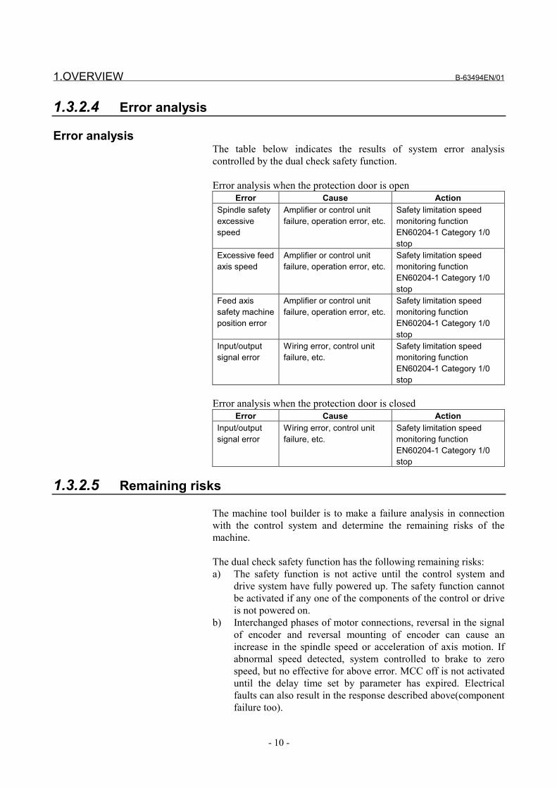
Error analysisThe table below indicates the results of system error analysiscontrolled by the dual check safety function.
Error analysis when the protection door is openError Cause Action
Spindle safetyexcessivespeed
Amplifier or control unitfailure, operation error, etc.
Safety limitation speedmonitoring functionEN60204-1 Category 1/0stop
Excessive feedaxis speed
Amplifier or control unitfailure, operation error, etc.
Safety limitation speedmonitoring functionEN60204-1 Category 1/0stop
Feed axissafety machineposition error
Amplifier or control unitfailure, operation error, etc.
Safety limitation speedmonitoring functionEN60204-1 Category 1/0stop
Input/outputsignal error
Wiring error, control unitfailure, etc.
Safety limitation speedmonitoring functionEN60204-1 Category 1/0stop
Error analysis when the protection door is closedError Cause Action
Input/outputsignal error
Wiring error, control unitfailure, etc.
Safety limitation speedmonitoring functionEN60204-1 Category 1/0stop
1.3.2.5 Remaining risks
The machine tool builder is to make a failure analysis in connectionwith the control system and determine the remaining risks of themachine.
The dual check safety function has the following remaining risks:a) The safety function is not active until the control system and
drive system have fully powered up. The safety function cannotbe activated if any one of the components of the control or driveis not powered on.
b) Interchanged phases of motor connections, reversal in the signalof encoder and reversal mounting of encoder can cause anincrease in the spindle speed or acceleration of axis motion. Ifabnormal speed detected, system controlled to brake to zerospeed, but no effective for above error. MCC off is not activateduntil the delay time set by parameter has expired. Electricalfaults can also result in the response described above(componentfailure too).
B-63494EN/01 1.OVERVIEW
- 11 -
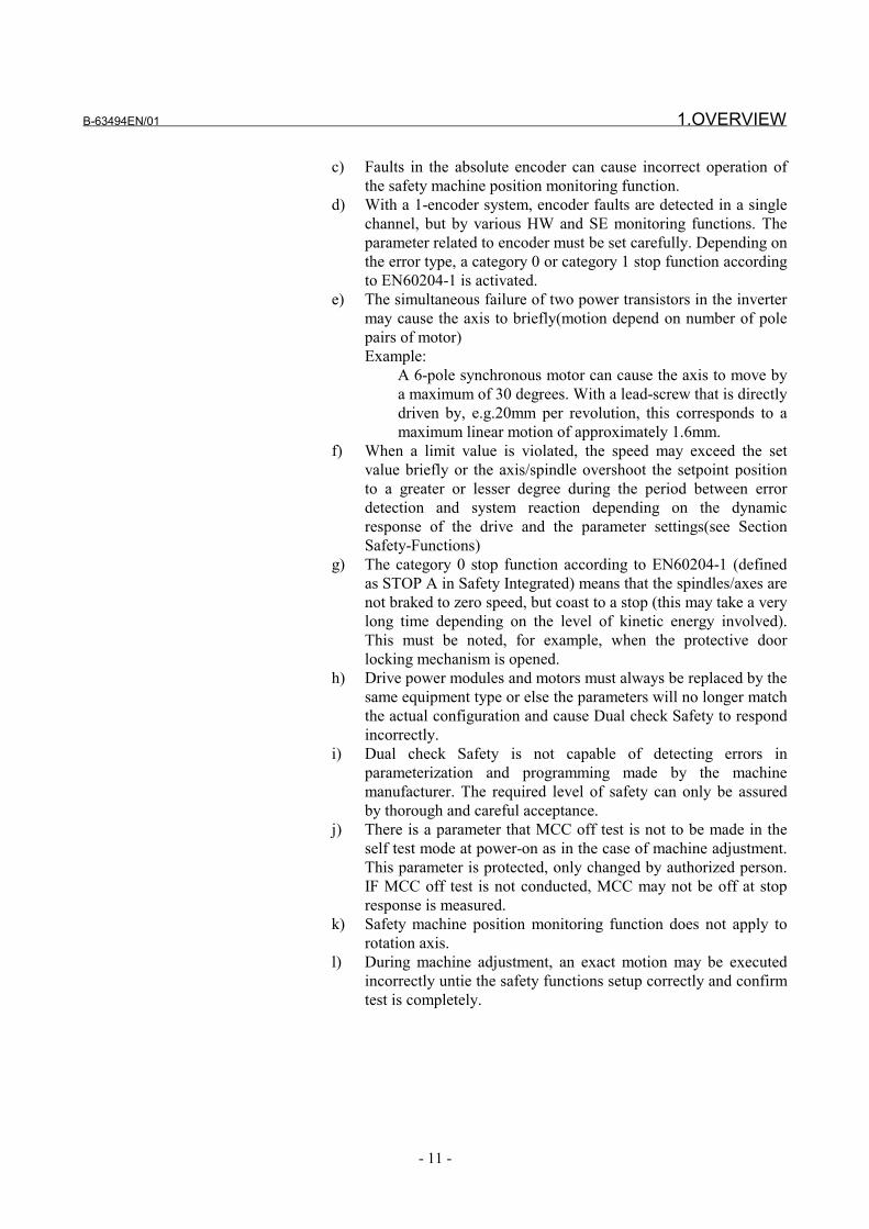
c) Faults in the absolute encoder can cause incorrect operation ofthe safety machine position monitoring function.
d) With a 1-encoder system, encoder faults are detected in a singlechannel, but by various HW and SE monitoring functions. Theparameter related to encoder must be set carefully. Depending onthe error type, a category 0 or category 1 stop function accordingto EN60204-1 is activated.
e) The simultaneous failure of two power transistors in the invertermay cause the axis to briefly(motion depend on number of polepairs of motor)Example:
A 6-pole synchronous motor can cause the axis to move bya maximum of 30 degrees. With a lead-screw that is directlydriven by, e.g.20mm per revolution, this corresponds to amaximum linear motion of approximately 1.6mm.
f) When a limit value is violated, the speed may exceed the setvalue briefly or the axis/spindle overshoot the setpoint positionto a greater or lesser degree during the period between errordetection and system reaction depending on the dynamicresponse of the drive and the parameter settings(see SectionSafety-Functions)
g) The category 0 stop function according to EN60204-1 (definedas STOP A in Safety Integrated) means that the spindles/axes arenot braked to zero speed, but coast to a stop (this may take a verylong time depending on the level of kinetic energy involved).This must be noted, for example, when the protective doorlocking mechanism is opened.
h) Drive power modules and motors must always be replaced by thesame equipment type or else the parameters will no longer matchthe actual configuration and cause Dual check Safety to respondincorrectly.
i) Dual check Safety is not capable of detecting errors inparameterization and programming made by the machinemanufacturer. The required level of safety can only be assuredby thorough and careful acceptance.
j) There is a parameter that MCC off test is not to be made in theself test mode at power-on as in the case of machine adjustment.This parameter is protected, only changed by authorized person.IF MCC off test is not conducted, MCC may not be off at stopresponse is measured.
k) Safety machine position monitoring function does not apply torotation axis.
l) During machine adjustment, an exact motion may be executedincorrectly untie the safety functions setup correctly and confirmtest is completely.
1.OVERVIEW B-63494EN/01
- 12 -
1.4 GENERAL INFORMATION
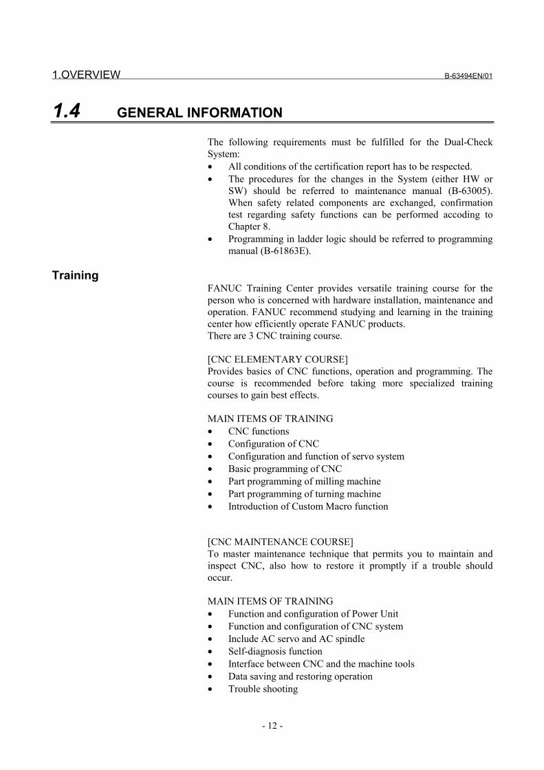
The following requirements must be fulfilled for the Dual-CheckSystem:• All conditions of the certification report has to be respected.• The procedures for the changes in the System (either HW or
SW) should be referred to maintenance manual (B-63005).When safety related components are exchanged, confirmationtest regarding safety functions can be performed accoding toChapter 8.
• Programming in ladder logic should be referred to programmingmanual (B-61863E).
TrainingFANUC Training Center provides versatile training course for theperson who is concerned with hardware installation, maintenance andoperation. FANUC recommend studying and learning in the trainingcenter how efficiently operate FANUC products.There are 3 CNC training course.
[CNC ELEMENTARY COURSE]Provides basics of CNC functions, operation and programming. Thecourse is recommended before taking more specialized trainingcourses to gain best effects.
MAIN ITEMS OF TRAINING• CNC functions• Configuration of CNC• Configuration and function of servo system• Basic programming of CNC• Part programming of milling machine• Part programming of turning machine• Introduction of Custom Macro function [CNC MAINTENANCE COURSE]To master maintenance technique that permits you to maintain andinspect CNC, also how to restore it promptly if a trouble shouldoccur. MAIN ITEMS OF TRAINING• Function and configuration of Power Unit• Function and configuration of CNC system• Include AC servo and AC spindle• Self-diagnosis function• Interface between CNC and the machine tools• Data saving and restoring operation• Trouble shooting
B-63494EN/01 1.OVERVIEW
- 13 -
[CNC SE INTERFACE COURSE]Training course offered to the engineers who design CNC machinetools or CNC application system for the first time. This course is alsosuitable for customers who provide to retrofitting, to develop anoriginal CNC machine tools or new application of CNC.
MAIN ITEMS OF TRAINING• Configuration of CNC system• Interface between CNC and machine tools• Ladder programming of machine control sequence• Setting of parameter related to machine• Setting of parameter related to servo and spindle
More information and course registrationYamanakako-mura, Yamanashi Prefecture : 401-0501, JAPANPhone : 81-555-84-6030Fax : 81-555-84-5540Internet:www.fanuc.co.jp/eschool

2.SYSTEM CONFIGURATION B-63494EN/01
- 14 -
2 SYSTEM CONFIGURATIONThe dual check safety function has the following components.
Applicable CNCFANUC Series 16i/18i/20i/21i/160is/180is/210is/160i/180i/210i(LCD-mounted type)FANUC Series 16i/18i/21i/160is/180is/210is/160i/180i/210i(stand-alone type)
Number of controlled axes- Series 20i/21i/210is/210i : 4 maximum- Series 18i/180is/180i : 6 maximum- Series 16i/160is/160i : 8 maximum
Number of spindle controlled axes- Series 21i/210is/210i : 2 maximum- Series 18i/180is/180i : 2 maximum- Series 16i/160is/160i : 2 maximum
Amplifier- α series servo amplifier- α series spindle amplifier- α series power supply module- αi series servo amplifier- αi series spindle amplifier- αi series power supply module
Motor- α series servo motor- α series spindle motor- β series servo motor- αi series servo motor- αi series spindle motor
I/O- I/O unit (I/O Link)- I/O module (FSSB)
Software- Dual check software
B-63494EN/01 2.SYSTEM CONFIGURATION
- 15 -
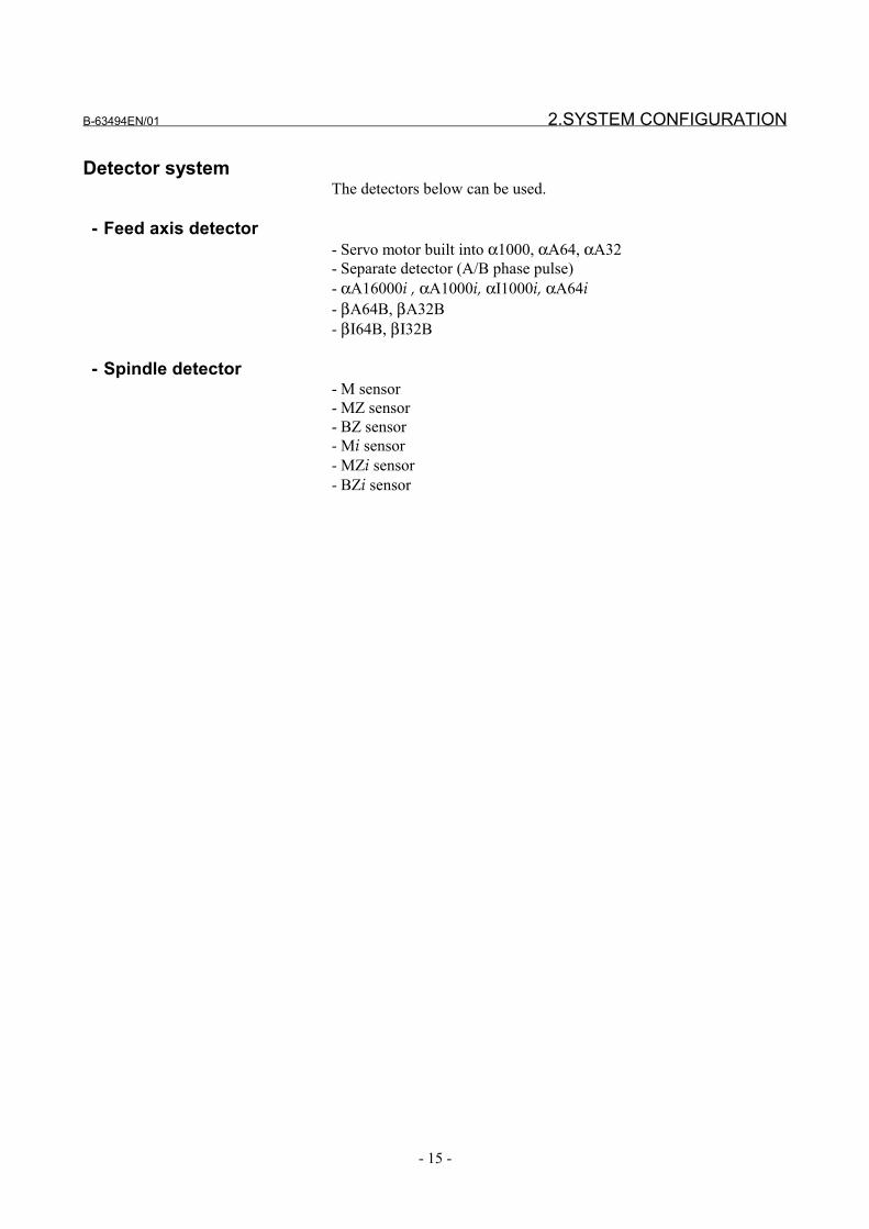
Detector systemThe detectors below can be used.
- Feed axis detector- Servo motor built into α1000, αA64, αA32- Separate detector (A/B phase pulse)- αA16000i , αA1000i, αI1000i, αA64i- βA64B, βA32B- βΙ64B, βΙ32B
- Spindle detector- M sensor- MZ sensor- BZ sensor- Mi sensor- MZi sensor- BZi sensor

3.SAFETY FUNCTIONS B-63494EN/01
- 16 -
3 SAFETY FUNCTIONS

B-63494EN/01 3.SAFETY FUNCTIONS
- 17 -
3.1 APPLICATION RANGE
The dual check safety function assumes the following configuration:
A) One protective door is provided.B) If the protective door is closed, safety is assured.
When the operator makes a request to open the protective door, thesafety functions are enabled, and the protective door can be unlocked.While the protective door is open, the active safety functions assuresafety. When the request to open the protective door is canceled, theprotective door is locked, and the safety functions are disabled.
The dual check safety function provides these safety functions whilethe protective door is open, as described above. Some of the safetyfunctions continue working while the protective door is closed.
WARNINGEach machine tool builder should take measures toassure safety while the protective door is closed andto ensure safety related to a rotation axis and travelaxis. At the same time, safety measures for theFANUC servo motor or spindle motor need to betaken, while the door is open.
The dual check safety function has the following safety functions:
Safe-related I/O signal monitoringThis function in redundant mode monitors I/O related to safety(emergency stop, protective door lock/open/close state, power-down)in redundant mode. The emergency stop, protective doorlock/open/close state, and power-down are checked in redundantmode. If the two corresponding inputs do not match, the systemjudges that an abnormal event has occurred. The power-down (MCCoff) signal is output in redundant mode (from two paths). Whether thetwo-path output is normal is judged in a MCC off Test.
Safe speed monitoringThis function checks that the rotation speeds of the servo motor andspindle motor are within a predetermined speed range, using twoCPUs in redundant mode. If a speed exceeding the range is detected,the system judges that an abnormal event has occurred.

3.SAFETY FUNCTIONS B-63494EN/01
- 18 -
Safe machine position monitoringThis function checks that the position on a servo axis is within aspecified range, using two CPUs in redundant mode. If a positionexceeding the range is detected, the system judges that an abnormalevent has occurred.
If an abnormal event (safety error) is found, the dual check safetyfunction shuts off the power to the motor driving circuit, using thetwo independent CPUs. The state in which the servo or spindle motorstops because of power-down is referred to as the safe stop state. If asafety error results in the safe stop state, the operator must turn off theCNC, remove the cause of the error, then turn on the CNC again. Theuser must conduct a MCC off Test every 24 hours in order to detect apotential cause of error.
CAUTIONThis safety function is enabled while the protectivedoor is open after a request to open the protectivedoor is made. If the request to open the protectivedoor is canceled and if the protective door is closed,this safety function is disabled.The dual input check of the safe-related I/O signalmonitoring function and the emergency stop functionare always active, regardless of whether theprotective door is opened or closed.

B-63494EN/01 3.SAFETY FUNCTIONS
- 19 -
Protectivedoor
Emergency
stop
Servo motor
Spindlemotor
Power-down(MCC)
CNCCPU
MonitorCPU
Spindle CPU
PSM
SVM
SPM
Safe speed monitoring
Safe speed monitoringSafe machine positionmonitoring
Door lock/open/closemonitoring Cross-check
Cross-check
CNC
Dual monitoring of MCCDual power-downDetection of potential cause of error byMCC off test
I/O, safe speed of theservo motor, andmachine position arechecked by the CNCCPU and monitorCPU in redundantmode.
The safe speed of thespindle motor ischecked by the CNCCPU and spindleCPU in redundantmode.
Dual monitoring of protective door state
Protective door
lock signal
Power-down
Dual monitoring of MCC
Dual monitoring of emergency stopsignal
Safety functions• Safe-related I/O signal monitoring
Emergency stop input, protective door lock/open/close state,relay state for turning off the MCC
• Dual signal outputOutput signal for shutting off the power (turning the MCCoff)To detect the potential cause of an abnormal state of thisoutput, a MCC off Test must be made.
• Spindle motorSafe speed monitoring
• Servo motorSafe speed monitoringSafe machine position monitoring

3.SAFETY FUNCTIONS B-63494EN/01
- 20 -
3.2 BEFORE USING THE SAFETY FUNCTION
3.2.1 Important Items to Check Before Using the Safety Function
• When using the safety function for the first time upon assemblyof the machine, replacing a part, or changing a safety parameter(such as a safe speed limit or safe range as described in Chaptern), the user must check that all safety parameters are correct andthat all safety functions are working normally. A return referenceposition must be made on each axis. The user must also checkthe absolute position of the machine. For details, see Chapter 8,"START UP."
• If an absolute-position detector is used, and reference positionreturn has been performed once, reference position data is storedin the CNC memory. In this case, the user need not make areference position check.
• If an incremental pulse coder is being used, reference positiondata is lost each time the power to the CNC is turned off andthen back on. So, after the power is turned on, another referenceposition return operation must be performed.
• At the every power on the safety area must be tested.
• At each power on there is a message: "Please execute safety test"Without this message dual check safety is either not installed ornot yet activated (option bit).
3.2.2 MCC off Test of the Safe Stop Function
A MCC off Test of the safe stop function monitors the contact state ofthe electromagnetic contactor (MCC), compares the state with acommand to the electromagnetic contactor, and checks that the safestop function works normally. The test must be carried out by the userof the machine. This test must be carried out when the CNC is turnedon or when 24 hours have elapsed after the previous test is completed.If the CNC is turned on or if 24 hours have elapsed after the previoustest is completed, a guard open request (protective door open request)is not accepted until the test is performed.

B-63494EN/01 3.SAFETY FUNCTIONS
- 21 -
3.3 STOP
3.3.1 Stopping the Spindle Motor
Because the spindle motor is an induction type motor, power-downduring rotation causes the motor to continue rotating for a certainamount of time. From a safety standpoint, the motor may have to bestopped immediately. If the CNC detects an error and judges that thespindle can be controlled, it waits until the rotation of the spindlestops, then shuts off the power. This wait period can be specified as asafety parameter. For this safety parameter, two different values canbe specified. One value is used when the safety function is active (thedoor is open), and the other value is used otherwise. The values mustbe determined in consideration of the stop period calculated from thespindle speed.
To implement the function, the CNC CPU and monitor CPUindividually incorporate a timer function. Normal operation of the twoCPUs are mutually checked to ensure the safety of the timers.
To speed down and stop the spindle, the PMC must input the spindleemergency stop signals (*ESPA(G71.1), *ESPB(G75.1), and so on).When this signal is input, the spindle slows down and stops. (ALadder program for inputting this signal in case of alarm must becreated.) The emergency stop input (connector CX4) of the PSM hasthe same effect. If the emergency stop signal is connected toemergency stop input (connector CX4) of the PSM, the spindle slowsdown and stops in the emergency stop state.
If this processing is not performed, power-down causes the spindlemotor to continue rotating at the speed prior to power-down (andeventually stopping in the end).
CAUTIONThe CNC outputs a DO notifying of an alarm. Ifnecessary, the spindle should be stopped. Becausethe DO output is not duplicated, this DO may not beoutput when a single failure is detected. In that case,the speed cannot be reduced, but the MCC is finallyshut off and brought into the safe stop state.If a spindle amplifier alarm or any other state inwhich the spindle motor cannot be controlled isencountered, immediate power-down is carried out.

3.SAFETY FUNCTIONS B-63494EN/01
- 22 -
3.3.2 Stopping the Servo Motor
Because the servo motor is a synchronous motor, power-down resultsin a dynamic brake stop. The dynamic brake stop is electric braking inwhich the excited rotor is isolated from the power source and thegenerated electric energy is used up in the winding. Additionalbraking is provided by an internal resistor. Unlike an induction motor,the servo motor does not coast because of this function.If the input of the emergency stop signal or an error of a safe-relatedsignal or speed monitoring is detected, the CNC automaticallyspecifies a command to zero the speed and reduces the speed to zero(controlled stop). After the motor slows down and stops, the power isturned off, and the motor is brought into the dynamic brake stop state.To slow down and stop the motor, some parameters must be specifiedin the CNC. If those parameters are not specified, the motor isimmediately brought into the dynamic brake stop state. In somecircumstances where a controlled stop cannot be made, a dynamicbrake stop is unconditionally made.
3.3.3 Stop States
The following stop states are possible:
Safe stop stateThe power to the motor is shut off (MCC off state). If the spindlemotor can be controlled, the power is shut off after the spindle motoris slowed down to a stop. If the spindle motor cannot be controlled,the power is immediately shut off.
If the servo motor can be controlled, the motor is slowed down to astop and then brought into the dynamic brake stop state. If the motorcannot be controlled, the motor is immediately brought into thedynamic brake stop state.If the power is shut off immediately, the spindle motor continues atthe same speed prior to the abnormal event and eventually comes to astop. If the spindle motor can be slowed down to a stop, the operationis performed as instructed by the PMC and then the power is shut off.
IMPORTANTThe time period until the signal for shutting off thepower (turning off the MCC) is output depends onthe parameter. Different parameters are used in thesafety monitoring state and in other states.
Safety parameter number Name1947 MCC off timer 1 If the protective door
is closed1948 MCC off timer 2 If the protective door
is opened

B-63494EN/01 3.SAFETY FUNCTIONS
- 23 -
Controlled stop stateThe power to the motor is not shut off.The servo motor and the spindle motor are controlled to stop.
In the controlled stop state of either motor, the safety function isactive if the condition for enabling the safety function is satisfied (thedoor is open). If a further abnormal event occurs, the motor is broughtinto the safe stop state.
WARNING1 The machine tool builder must design the machine
so that the machine is kept in the stop state if thepower to the servo motor driving circuit is shut off.Example) Brake mechanism that would not drop thevertical axis after the power is shut off
2 If the power to the spindle motor driving circuit is shutoff, the spindle motor continues rotating at the speedbefore the power-down and eventually comes to astop. A measure must be taken so that this coastingdoes not affect safety.

3.SAFETY FUNCTIONS B-63494EN/01
- 24 -
3.4 SAFE-RELATED I/O SIGNAL MONITORING
A set of safe-related I/O signals are connected to the I/O Link and theservo FSSB through separate paths. The two independent CPUsindividually check the input signals. If a mismatch between twocorresponding signals is found, the system enters the safe stop state.The following safe-related I/O signals are monitored or output inredundant mode:
• Emergency stop input signal• Protective door state input signal• Lock state input signal• Input signal for monitoring the MCC contact state• Output signal for turning off the MCC (power-down)
To configure the two-path system, the machine tool builder mustconnect these signals to both the I/O module and the FSSB I/O.
IMPORTANTIf the safety input signals, except for emergency stopinput signals, are connected to the I/O module, aLadder program must be created to establish a one-to-one relationship between the actual input (X) andthe input to the CNC (G).
The duplicated input signals are always checked for a mismatch,regardless of whether the safety function is active or not. When asignal state changes, the pair of signals may not match for someperiod because of a difference in response. The dual check safetyfunction checks whether a mismatch between the two signalscontinues for a certain period of time, so that an error resulting fromthe difference in response can be avoided. The check period must bespecified as a safety parameter.
Parameter No. Name1945 Safe-related input signal check timer
The following signals are not defined as safe-related I/O signals andare not duplicated. The signals, however, are necessary for thesystem.
- Input signal for making a protective door open request - Input signal for starting the test mode - Output signal for specifying a command to lock the protective door - Output signal for requesting a MCC off Test
This section briefly describes the signals. For details, see Chapter 5,"OPERATION." For specific connections, see the sample systemconfiguration in Chapter 10.

B-63494EN/01 3.SAFETY FUNCTIONS
- 25 -
CNCCPU
MonitorCPU
I/O LINK
FSSB
I/O UNIT
FSSB I/O
DI
DI
DO
DO
Cross check
MachineCNC
Duplicated I/O
Symbol Signal name I/O address*ESP Emergency stop signal <X008#4> <DI+000#0> Dual input monitoringSGD Guard state signal <G191#4> <DI+001#4> Dual input monitoringGDL Guard lock state signal <G191#5> <DI+001#5> Dual input monitoring*SMC MCC contact state signal <G191#6> <DI+001#6> Dual input monitoringMCF MCC on enable signal <F191#1> <DO+000#1> Duplicated outputORQ Guard open request
signal<G191#3> Input
OPT Test mode signal <G191#2> Input*LGD Guard unlock signal <F191#0> OutputRQT MCC off Test execution
request signal<F191#2> Output
Safe-related I/O
1. *ESP Emergency stop signal (input)Emergency stop signal. The signal is monitored in redundant mode.The signal is connected to the *ESP input of the servo amplifier aswell.
2. SGD Guard state signal (input)The signal is provided for double monitoring of the protective doorstate. The signal is connected so that it is normally set to 1 while theprotective door is closed and locked (door open) and set to 0otherwise (door close). These states are implemented by thecombination of the safety door and safety relays. The CNC monitorsthese states. If the safe speed range is exceeded in the door open state,the system enters the safe stop state.
3. GDL Guard lock state signal (input)This signal is not usually used.
3.SAFETY FUNCTIONS B-63494EN/01
- 26 -
4. *SMC MCC contact state signal (input)The MCC contact state is monitored in redundant mode. In normaloperation, the MCC is active, and whether the contact of a relay isclosed cannot be detected. In the test mode, a closed contact of a relaycan be detected.
5. MCF MCC on enable signal (output)With this signal, the MCC is shut off from both the I/O Link side andthe FSSB side.
Signals other than safe-related I/OThe following signals are not safe-related signals (are not checked inredundant mode) but are important signals in the system. The machinetool builder must create an appropriate Ladder program.
IMPORTANTThe Ladder program cannot be checked for an error.Check the safety function (see Chapter 7).
6. ORQ Guard open request signal (input)When this signal is input, the CNC checks the machine position andspeed. If both the machine position and speed are within the saferange, the guard unlock signal (*LGD) is set to 1 (guard unlockenabled). The machine tool builder must provide an output signal thatopens the actual protective door through the PMC. Connect the signaloutput.
7. OPT Test mode signal (input)When the signal is input, a MCC off Test is executed. The MCC offTest checks whether the contact of the MCC is closed. When carryingout the MCC off Test manually, execute a MCC off Test by the PMCand make necessary corrections before inputting this signal.
8. *LGD Guard unlock signal (output)If this signal is set to 1, the protective door can be unlocked. Then, asignal to unlock the actual protective door should be output throughthe PMC.If the protective door is unlocked while the signal is set to 0, an alarmoccurs and brings the motor into the safe stop state.
CAUTIONWhen the signal is set to 1, there is a time delay(depending on the Ladder program) before the signalto unlock the actual protective door is output.Meanwhile, the protective door is locked, and safetyis ensured. If an error is found as a result of speedcheck or machine position check during that period,*LGD becomes 0. If a single failure occurs in thisstate and if the actual protective door is unlocked, analarm occurs.
B-63494EN/01 3.SAFETY FUNCTIONS
- 27 -
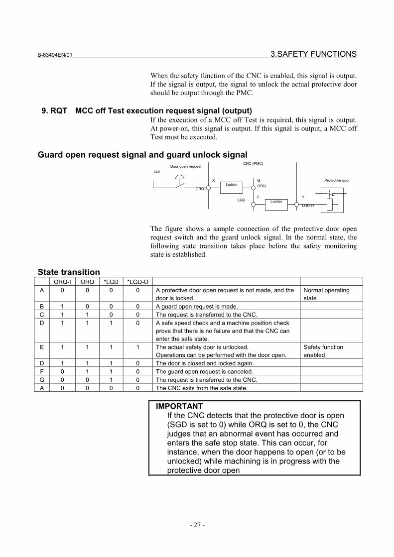
When the safety function of the CNC is enabled, this signal is output.If the signal is output, the signal to unlock the actual protective doorshould be output through the PMC.
9. RQT MCC off Test execution request signal (output)If the execution of a MCC off Test is required, this signal is output.At power-on, this signal is output. If this signal is output, a MCC offTest must be executed.
Guard open request signal and guard unlock signal
24V
X
Door open request
Ladder
Ladder
ORQ-IORQ
LGDLGD-O
G
F Y
Protective door
CNC (PMC)
The figure shows a sample connection of the protective door openrequest switch and the guard unlock signal. In the normal state, thefollowing state transition takes place before the safety monitoringstate is established.
State transitionORQ-I ORQ *LGD *LGD-O
A 0 0 0 0 A protective door open request is not made, and thedoor is locked.
Normal operatingstate
B 1 0 0 0 A guard open request is made.C 1 1 0 0 The request is transferred to the CNC.D 1 1 1 0 A safe speed check and a machine position check
prove that there is no failure and that the CNC canenter the safe state.
E 1 1 1 1 The actual safety door is unlocked.Operations can be performed with the door open.
Safety functionenabled
D 1 1 1 0 The door is closed and locked again.F 0 1 1 0 The guard open request is canceled.G 0 0 1 0 The request is transferred to the CNC.A 0 0 0 0 The CNC exits from the safe state.
IMPORTANTIf the CNC detects that the protective door is open(SGD is set to 0) while ORQ is set to 0, the CNCjudges that an abnormal event has occurred andenters the safe stop state. This can occur, forinstance, when the door happens to open (or to beunlocked) while machining is in progress with theprotective door open

3.SAFETY FUNCTIONS B-63494EN/01
- 28 -
Timing diagram from door close state to door open state
The following diagram shows the timings at which the door is openedand closed again.
ORQ
*LGD
*LGD_P1(Actual door unlock signal)
SGD_PSGD2
Door closed Door opened
(1) (2) (3) (4) (5)
t
Door closed
ORQ_P
Actual door status
(1) When the guard open request signal (ORQ) is input, it checksthat the machine position and speed are within safe ranges. Then,the guard unlock signal (*LGD) is turned on.
(2) When *LGD goes on, the Ladder program turns on the unlocksignal. This example assumes that the protective door has anelectromagnetic lock mechanism. While the door is open, theunlock signal is turned off.
(3) The door is open.(4) The protective door is closed and locked. After this, the guard
open request signal (ORQ) must be turned off. CAUTIONReserve a time of 100 ms or longer (t in the figure)from when the door is closed (locked) until the guardopen request signal (ORQ) goes off. If this timerequirement is not satisfied, an alarm may be raisedwhen the door is closed (locked).
(5) When ORQ goes off, the CNC turns *LGD off.

B-63494EN/01 3.SAFETY FUNCTIONS
- 29 -
3.5 EMERGENCY STOP
The emergency stop signal is monitored in redundant mode. When theemergency stop is input, the servo motor slows down to a stop (*) andenters the dynamic brake stop. The spindle slows down to a stop(*) asinstructed by the PMC, and the power is shut off.
CAUTIONTo enable the function to slow down and stop theservo motor, the corresponding parameter must bespecified. If the parameter is not specified, the motorimmediately enters the dynamic brake stop state.The spindle motor slows down and stops asinstructed by the PMC (Ladder program). If the PMCdoes not instruct this, the motor maintains the highspeed prior to the power-down and coasts. If anillegal speed is specified because of a failure on thePMC side while the safety function is active (theprotective door is open), the CNC enters the safestop state.
WARNINGIn the emergency stop state, the guard unlock signalbecomes 1 (the door opens). In the emergency stopstate, the processing to open or close the protectivedoor depends on the Ladder program created by themachine tool builder. For instance, if the protectivedoor should not be opened in the emergency stopstate, a Ladder program of the processing must becreated.
When the emergency stop is canceled, an alarm may occur, dependingon the state. For instance, if the emergency stop state is canceled withthe protective door open and if no door open request is made, theCNC judges that an error has occurred and enters the safe stop state.
IMPORTANTEmergency Stop Button must fulfil the StandardIEC60947-5-1.This is mandatory.

3.SAFETY FUNCTIONS B-63494EN/01
- 30 -
3.6 SAFE SPEED MONITORING
When the guard open request signal is input, the dual check safetyfunction starts monitoring whether a safe speed is kept on each feedaxis and spindle. If the speed does not exceed the safe speed rangeand if the machine position is in within the safe range, the guardunlock signal is enabled. If the safe speed range is exceeded while theprotective door is open, the dual check safety function immediatelyenters the safe stop state. For each feed axis and spindle, a single safespeed range is specified in a safety parameter.
CAUTIONIf an illegal speed is detected, the MCC is shut offafter the time specified in the parameter.
IMPORTANT1 The period from when an error is detected until the
MCC is shut off can be specified in a parameter. Theperiod is reserved to stop the spindle safely. A largevalue means that a long time is needed to shut off theMCC. In this parameter, different values can bespecified and used when the safety function isenabled (the protective door is open) and disabled(normal operation is performed). The value of theparameter for the former case must be carefullyspecified.
2 A gear ratio, ball screw, and the like must be carefullyselected so that a safe speed can be kept on the feedaxis.
3 Before inputting the guard open request signal,reduce each axial speed and spindle speed to a safespeed range or below. If a speed exceeds the limit,the guard open request signal is not accepted (thedoor is not unlocked). If the door is forced open, thepower to the driving circuit is shut off (safe stop state).
WARNINGThe safe speed monitoring function monitors whetherthe traveling speed exceeds a specified limit. Thefunction cannot monitor the stop state (zero speed).If an error causes a movement on the feed axis at aspeed lower than the safe speed range while theprotective door is open, for instance, the functioncannot detect this state. The machine must bedesigned so that this state does not affect the safetyof the machine system.

B-63494EN/01 3.SAFETY FUNCTIONS
- 31 -
3.7 SAFE MACHINE POSITION MONITORING
While the door is open, the dual check safety function checks whetherthe position on each feed axis is within the safe machine positionrange defined by safety parameters. If it detects a machine positionbeyond the safety range, the dual check safety function immediatelyenters the safe stop state.
The user of the machine must first carry out a reference positionreturn in order to obtain the initial position. If the reference positionreturn is not carried out, the check function is disabled. This checkfunction is enabled after the reference position is established. (Thefunction cannot be disabled by any means after the reference positionis established.) A safe machine position limit on each feed axis isspecified in a safety parameter.
CAUTIONThe safe machine position monitoring function doesnot keep monitoring the specified range. Only afterthe function detects that a position on a feed axisexceeds the range, the system enters the safe stopstate. Accordingly, in the safe stop state, anovertravel has occurred on the feed axis. The traveldistance depends on the traveling speed and otherconditions.
At power-on, the safety function does not work. After power-on, theCNC checks whether a reference position return is completed. If thereference position return is completed and if the protective door isopen, safe machine position monitoring and safe speed monitoring areperformed. Then, the safety functions start working. If the referenceposition return is not completed, safe machine position monitoringcannot be performed because the coordinates are not set. In this state,the machine position monitoring function is disabled. After areference position return is made, this function is enabled. Dependingon the safety parameter setting, however, an alarm may be raised. Toavoid this alarm, specify the safe machine position parameters beforemaking a reference position return.

3.SAFETY FUNCTIONS B-63494EN/01
- 32 -
3.8 MCC OFF TEST
A MCC off Test must be carried out in intervals of 24 hours, so thatthe safety functions would not be damaged by a possible cause offailure. A message telling that the MCC off Test must be carried outis displayed at power-on or when 24 hours have elapsed after theprevious MCC off Test. The protective door can be opened only afterthe MCC off Test is carried out accordingly.
IMPORTANTCarry out the MCC off Test with the protective doorclosed. Because the test shuts off the MCC, preparethe system for mechanical MCC shut-off beforestarting the MCC off Test.

B-63494EN/01 4.INSTALLATION
- 33 -
4 INSTALLATIONExcept FSSB I/O module, the hardware installation such as fieldwiring, power supply, etc. should be referred to connection manual(B-63003EN) for CNC units and (B-65162E) for servo amplifier.EMC problem should be referred to EMC guideline manual (A-72937/E).
Degree of IP protection:Servo Motors: IP55Spindle Motors: IP54 with oil-seal, IP40 without oil-sealServo and Spindle amplifiers: IP1xCNC and other accessories: Ipxx
NOTEServo/Spindle amplifiers, CNC are to be installed inIP54 protected cabinets.
The peripheral units and the control unit have been designed on theassumption that they are housed in closed cabinets.
Environmental conditions for CNC unitsCondition LCD–mounted
type controlunit and display
unit (exceptunit with data
server function)
Stand–alonetype control
unit
LCD–mountedtype controlunit with PC
and data serverfunctions
Operating 0°C to 58°C 0°C to 55°C 5°C to 53°CAmbientTemperature
of the unitStorageTransport
–20°C to 60°C
Normal 75% RH or less, no condensation 10% to 75% RH,no condensation
Humidity
Short period(lessthan 1 month)
95% RH or less, no condensation 10% to 90% RH,no condensation
Operating 0.5 G or lessVibrationNon–operating 1.0 G or lessOperating Up to 1000 m Up to 1000 mMeters above
sea level Non–operating Up to 12000 m Up to 12000 mEnvironment Normal machine shop environment (The environment must be
considered if the cabinets are in a location where the density of dust,coolant, and/or organic solvent is relatively high.)

4.INSTALLATION B-63494EN/01
- 34 -
Environmental conditions for servo amplifier
The servo amplifier α series must be installed in a sealed type cabinetto satisfy the following environmental requirements:
(1) Ambient TemperatureAmbient temperature of the unit :0 to 55°C (at operation)-20 to 60°C (at keeping and transportation)
(2) HumidityNormally 90% RH or below, and condensation-free
(3) VibrationIn operation : Below 0.5G
(4) AtmosphereNo corrosive or conductive mists or drops should depositdirectly on the electronic circuits.
B-63494EN/01 4.INSTALLATION
- 35 -
4.1 OVERALL CONNECTION DIAGRAM
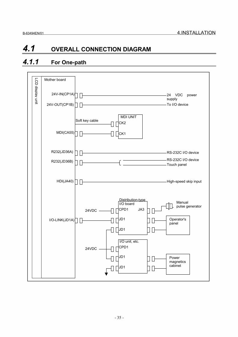
4.1.1 For One-path
Mother board
LCD
display unit
I/O-LINK(JD1A)
24 VDC powersupply
24V-IN(CP1A)
24V-OUT(CP1B) To I/O device
MDI UNITCK2
CK1
Soft key cable
MDI(CA55)
R232(JD36A)
R232(JD36B)
RS-232C I/O device
RS-232C I/O deviceTouch panel
HDI(JA40) High-speed skip input
Distribution-typeI/O boardCPD1
JD1
JD1
JA3
Operator'spanel
I/O unit, etc.CPD1
JD1
JD1
Powermagneticscabinet
24VDC
24VDC
Manualpulse generator
4.INSTALLATION B-63494EN/01
- 36 -
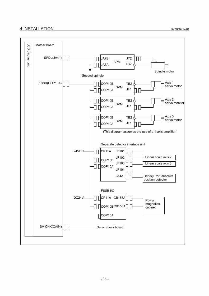
Mother board
LCD
display unit
SPDL(JA41) JA7B
JA7A
JY2
TB2
Spindle motorSecond spindle
FSSB(COP10A) Axis 1servo motor
COP10B
COP10A
TB2
JF1
SPM
SVM
COP10B
COP10A
TB2
JF1SVMAxis 2servo monitor
COP10B
COP10A
TB2
JF1SVMAxis 3servo motor
COP10B
COP10A
JF101
JF102
(This diagram assumes the use of a 1-axis amplifier.)
JF103
JF104
JA4A
Linear scale axis 2
Linear scale axis 3
Battery for absoluteposition detector
Separate detector interface unit
COP10B
COP10A
CB155A
CB156A
FSSB I/O
CP11A
CP11APowermagneticscabinet
DC24V
24VDC
SV-CHK(CA54) Servo check board
B-63494EN/01 4.INSTALLATION
- 37 -
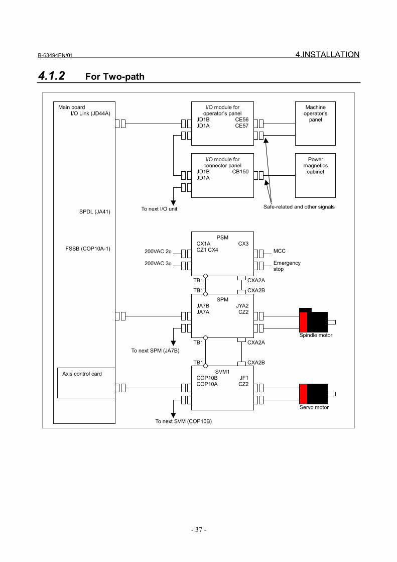
4.1.2 For Two-path
Main boardI/O Link (JD44A)
SPDL (JA41)
FSSB (COP10A-1)
I/O module foroperator’s panel
JD1B CE56JD1A CE57
Machineoperator’s
panel
I/O module forconnector panel
JD1B CB150JD1A
To next I/O unit
Powermagnetics
cabinet
200VAC 2φ
SPMJA7B JYA2JA7A CZ2
PSMCX1A CX3CZ1 CX4
TB1
TB1 CXA2A
CXA2B
200VAC 3φ
Safe-related and other signals
Spindle motor
MCC
Emergencystop
To next SPM (JA7B)
SVM1COP10B JF1COP10A CZ2
TB1
TB1 CXA2A
CXA2B
Servo motor
To next SVM (COP10B)
Axis control card

4.INSTALLATION B-63494EN/01
- 38 -
Separate detectorinterface unit
COP10B JF101COP10A JF102
JF103JF104JA4A
From previous SVM (COP10A)
SeparatedetectorSeparatedetectorSeparatedetectorSeparatedetectorBattery
FSSB I/O moduleCOP10B CB155COP10A CB156
Powermagnetics
cabinet
Safe-related signals
B-63494EN/01 4.INSTALLATION
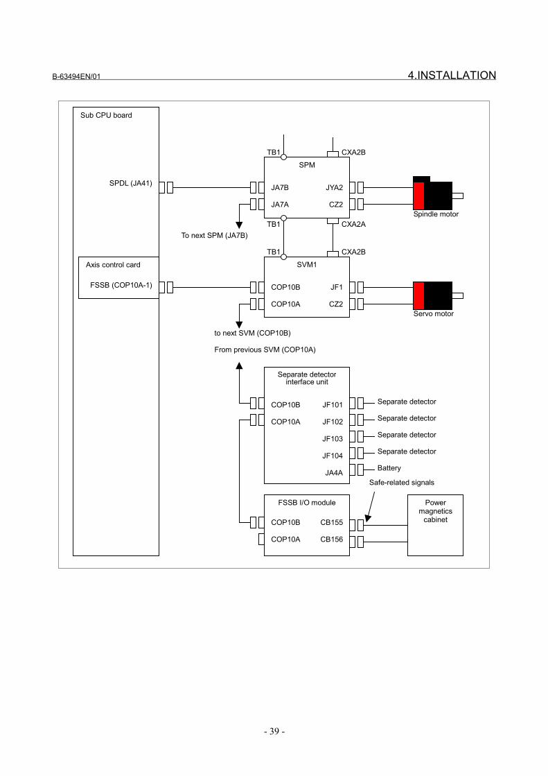
- 39 -
Sub CPU board
SPDL (JA41)
FSSB (COP10A-1)
SPM
JA7B JYA2
JA7A CZ2
TB1 CXA2B
Spindle motor
SVM1
COP10B JF1
COP10A CZ2
TB1
TB1 CXA2A
CXA2B
Servo motor
Separate detectorinterface unit
COP10B JF101
COP10A JF102
JF103
JF104
JA4A
Separate detector
Separate detector
Separate detector
Separate detector
Battery
FSSB I/O module
COP10B CB155
COP10A CB156
Powermagnetics
cabinet
Safe-related signals
Axis control card
To next SPM (JA7B)
to next SVM (COP10B)
From previous SVM (COP10A)
4.INSTALLATION B-63494EN/01
- 40 -
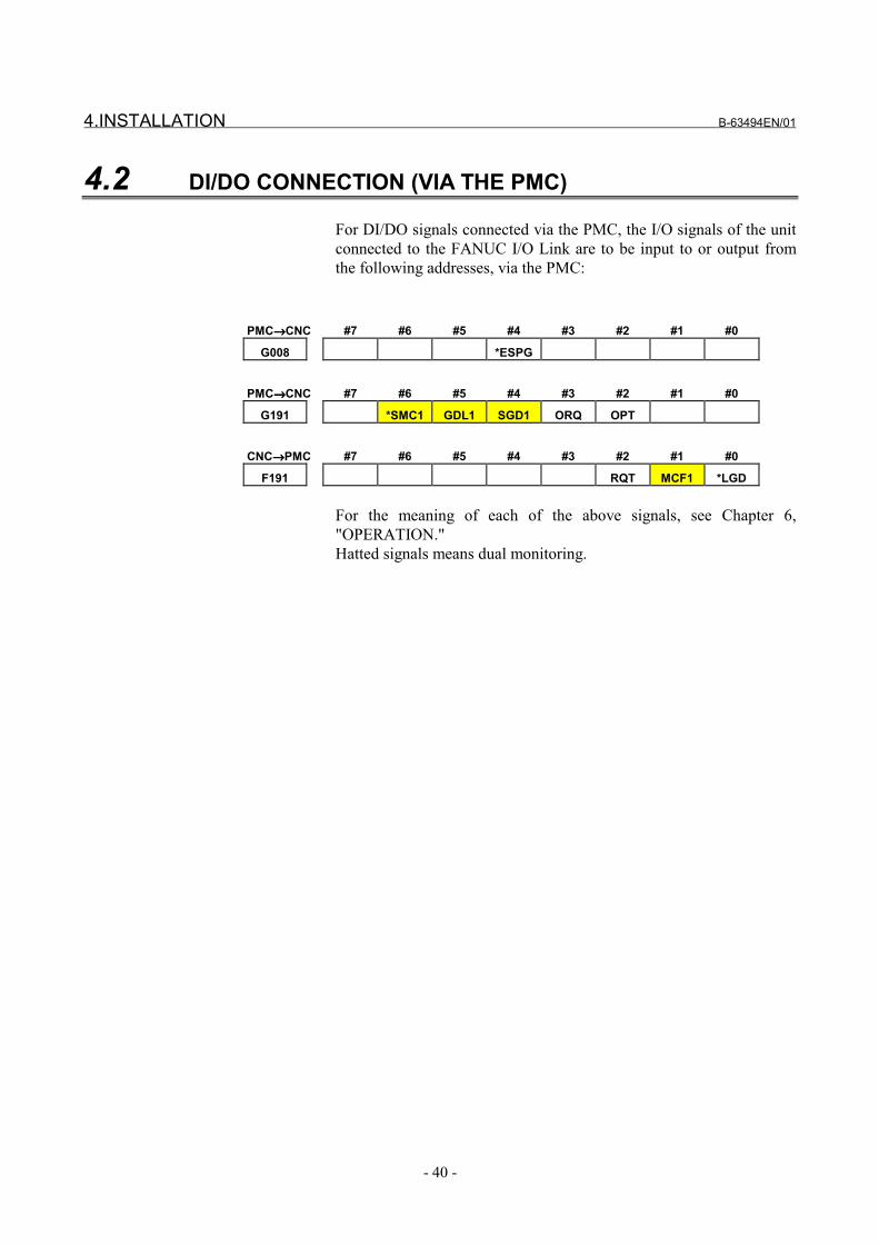
4.2 DI/DO CONNECTION (VIA THE PMC)
For DI/DO signals connected via the PMC, the I/O signals of the unitconnected to the FANUC I/O Link are to be input to or output fromthe following addresses, via the PMC:
PMC→→→→CNC #7 #6 #5 #4 #3 #2 #1 #0
G008 *ESPG
PMC→→→→CNC #7 #6 #5 #4 #3 #2 #1 #0
G191 *SMC1 GDL1 SGD1 ORQ OPT
CNC→→→→PMC #7 #6 #5 #4 #3 #2 #1 #0
F191 RQT MCF1 *LGD
For the meaning of each of the above signals, see Chapter 6,"OPERATION."Hatted signals means dual monitoring.
B-63494EN/01 4.INSTALLATION
- 41 -
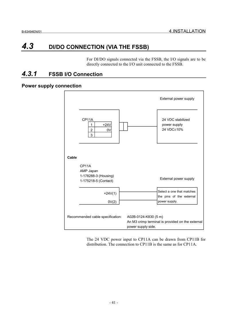
4.3 DI/DO CONNECTION (VIA THE FSSB)
For DI/DO signals connected via the FSSB, the I/O signals are to bedirectly connected to the I/O unit connected to the FSSB.
4.3.1 FSSB I/O Connection
Power supply connection
CP11AAMP Japan1-178288-3 (Housing)1-175218-5 (Contact)
0V(2)
+24V(1)
External power supply
External power supply
CP11A1 +24V2 0V3
Select a one that matchesthe pins of the externalpower supply.
24 VDC stabilizedpower supply24 VDC±10%
Cable
Recommended cable specification: A02B-0124-K830 (5 m)An M3 crimp terminal is provided on the externalpower supply side.
The 24 VDC power input to CP11A can be drawn from CP11B fordistribution. The connection to CP11B is the same as for CP11A.

4.INSTALLATION B-63494EN/01
- 42 -
DI/DO connection
RV
RV
RV
RV
RV
RV
RV
RV
+24V CB155A(A01)CB155A(B01)
CB155A(A02)
Pin No.
*ESP2
SMC2
GDL2
SGD2
Signal name
CB155A(A07)
CB155A(B07)
CB155A(A08)
CB155A(B08)
CB155A(A09)
CB155A(B09)
CB155A(A10)
DOCOM CB155A(B06)
CB155A(A11)
Pin No.
Signal name
DV
+24V stabilizedpower supply
+24V 0V
Relay
DVMCF2
CB155A(A17,B17)
CB155A(B11) Relay
For the meanings of the above signals, see Chapter 6,"OPERATION."

B-63494EN/01 4.INSTALLATION
- 43 -
4.3.2 FSSB I/O Attachment
External dimensions
CP11ACP11B
Upper:CB156ALower:CB155A
COP10A COP10B

4.INSTALLATION B-63494EN/01
- 44 -
Screw attachment
Mounting holemachining diagram
B-63494EN/01 4.INSTALLATION
- 45 -
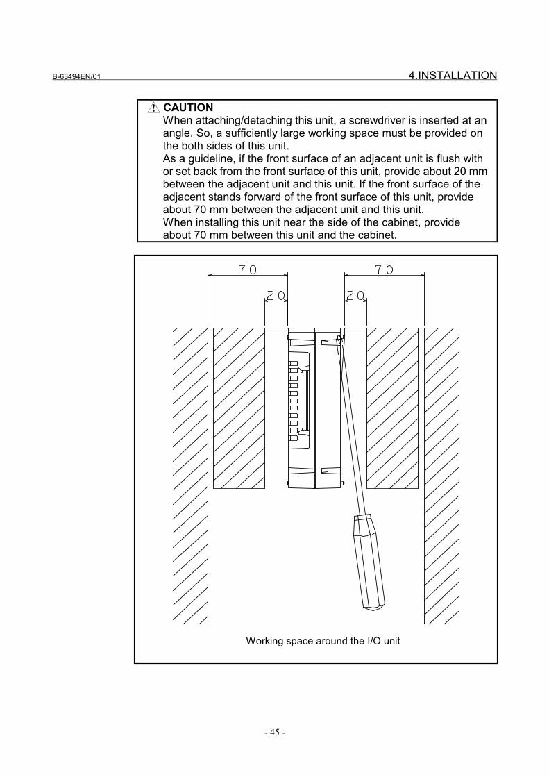
CAUTIONWhen attaching/detaching this unit, a screwdriver is inserted at anangle. So, a sufficiently large working space must be provided onthe both sides of this unit.As a guideline, if the front surface of an adjacent unit is flush withor set back from the front surface of this unit, provide about 20 mmbetween the adjacent unit and this unit. If the front surface of theadjacent stands forward of the front surface of this unit, provideabout 70 mm between the adjacent unit and this unit.When installing this unit near the side of the cabinet, provideabout 70 mm between this unit and the cabinet.
Working space around the I/O unit

4.INSTALLATION B-63494EN/01
- 46 -
Attachment to a DIN rail
Detachment
Attachment
DIN rail
DIN rail
Attachment1. Hook the unit over the top of the DIN rail.2. Press the unit down until it snaps into place.
Detachment1. Pull down the lock section with a standard screwdriver.2. Pull the lower part of the unit toward you.
CAUTIONWhen detaching the unit, be careful not to damagethe lock section by applying excessive force.When attaching or detaching the unit, hold theupper and lower parts of the unit, if possible, toprevent force from being applied to the side (wherethe cooling rents are provided) of the unit.

B-63494EN/01 4.INSTALLATION
- 47 -
4.3.3 FSSB I/O Specification List
Installation conditionsAmbient temperature
of the unitOperating 0°C to 55°CStorage, transportation -20°C to 60°C
Temperature variation 1.1°C /minute maximum
Humidity
Normally Relative humidity 75% or lessShort term (no more than one month)
Relative humidity 95% or lessVibration Operating 0.5G or less
Atmosphere
Normal machining plant environment (Check isrequired if the unit is to be used in anenvironment exposed to relatively high levels ofdust or coolant, or a relatively high concentrationof organic solvents.)
Other conditions
(1) Use the unit in a completely sealed cabinet.(2) Install the unit on a vertical surface, and
provide a space of 100 mm or more aboveand below the unit. Do not install equipmentthat dissipates much heat under this unit.
Power supply capacitySupply voltage Power supply
capacity Remarks
24V±10% is fed from the CP11Aconnector of the basic module.±10% includes momentaryvariations and ripples.
0.3A+7.3mAxDI Number of DI pointsin DI = ON state
Input signal specificationsContact capacity 30 VDC, 16 mA or more
Leakage current betweenopen contacts 1 mA or less (when the voltage is 26.4 V)
Voltage drop across closedcontacts
2 V or less (including a cable voltagedecrease)
Delay timeReceiver delay time: 2 ms (MAX)In addition, the FSSB transfer period andladder scan period need to be considered.
Output signal specificationsMaximum load current at
ON time200 mA or less including momentaryvariations
Saturation voltage at ONtime 1 V (MAX) when the load current is 200 mA
Dielectric voltage 24 V +20% or less including momentaryvariations
Output leakage current atOFF time 20 µA or less
Delay timeDriver delay time: 50 µs(MAX)In addition, the FSSB transfer period andladder scan period must be considered.

5.I/O SIGNALS B-63494EN/01
- 48 -
5 I/O SIGNALS

B-63494EN/01 5.I/O SIGNALS
- 49 -
5.1 OVERVIEW
The dual check safety function provides two input paths and twooutput paths for safe-related signals (safety signals).For input signals (safety input signals), two paths are used: one pathfor input to the CNC via the PMC, and the other for input to themonitor via the FSSB. The CNC and monitor exchange the safetyinput signals with each other at all times to check each other. If amismatch is found between a safety input signal via one path and thesame signal via the other path, the signal is assumed to be 0. If such astate lasts for the period set in a parameter or more, the CNC andmonitor independently detect an alarm. (Dual-check for safety inputsignals)For output signals (safety output signals), two paths are used: onepath for output from the CNC via the PMC, and the other for outputfrom the monitor via the FSSB. The MCC-on enable signal (MCF) isoutput via these two paths. When both a signal via one path and thesame signal via the other path are 1, the signal is assumed to be 1. Ifeither is 0, the signal is assumed to be 0. That is, if the signal (MCF1)via the PMC and the signal (MCF2) via the FSSB are both 1, theMCC may be turned on. If either is 0, the MCC must be turned off.
In Subsection 5.2, a signal name is followed by its symbol andaddresses <via PMC> and <via FSSB>. Then, for an input signal, itsclassification, function, and operation are described, in this order. Foran output signal, its classification, function, and output condition aredescribed in this order.
For information about the emergency stop mode, MCC off Test mode,and safety signal modes A/B/C/D described in Subsection 5.2, seeSubsection 5.2.2.

5.I/O SIGNALS B-63494EN/01
- 50 -
5.2 SIGNALS
Emergency stop signal*ESP1 <X008#4>(<X1000#7> for loader control), *ESPG <G008#4>,*ESP2 <DI+000#0>
[Classification] Input signal[Function] Stops machine movement immediately in an emergency.
[Operation] When emergency stop signal (*ESP) is set to 0, the CNC is reset, andan emergency stop occurs. In general, emergency stop signal (*ESP)is specified by the pushbutton switch B contact. When an emergencystop occurs, the servo ready signal SA is set to 0.When emergency stop signal (*ESP) is set to 0, the emergency stopmode is set with the dual check safety function. In this mode, theMCC contact state signal (*SMC) is checked. When *SMC = 0(MCC-on state ), the guard unlock signal (*LGD) is set to 0 (todisable guard unlocking). When *SMC = 1 (MCC-off state), the guardunlock signal (*LGD) is set to 1 (to enable guard unlocking).
CAUTIONEmergency stop signals (*ESP) via the PMC<X008#4> (<X1000#7> for loader control) and viathe FSSB <DI+000#0> are checked each other(dual-check for safety input signals), but *ESP viathe PMC <G008#4> is not checked.
Test mode signalOPT <G191#2>
[Classification] Input signal[Function] This signal notifies the CNC that MCC off Test mode is set with the
dual check safety function.Test mode signal (OPT) is not input via the FSSB.
[Operation] When test mode signal (OPT) is 1, the CNC performs safety outputsignal MCC off Test processing. (MCC-on enable signals(MCF1/MCF2) is output in various patterns, and a test is conducted tosee if an appropriate MCC contact state signals (*SMC1/*SMC2)pattern is input, respectively.) In the emergency stop state or while aservo or spindle alarm is present, the MCC off test processing is notperformed.If a MCC off Test is not completed within the time set in parameterNo. 1946, servo alarm No. 488 is issued.
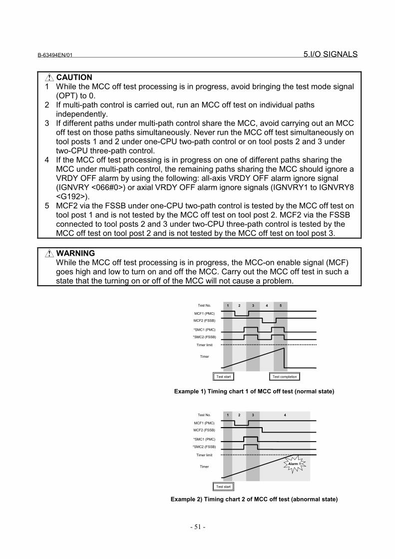
B-63494EN/01 5.I/O SIGNALS
- 51 -
CAUTION1 While the MCC off test processing is in progress, avoid bringing the test mode signal
(OPT) to 0.2 If multi-path control is carried out, run an MCC off test on individual paths
independently.3 If different paths under multi-path control share the MCC, avoid carrying out an MCC
off test on those paths simultaneously. Never run the MCC off test simultaneously ontool posts 1 and 2 under one-CPU two-path control or on tool posts 2 and 3 undertwo-CPU three-path control.
4 If the MCC off test processing is in progress on one of different paths sharing theMCC under multi-path control, the remaining paths sharing the MCC should ignore aVRDY OFF alarm by using the following: all-axis VRDY OFF alarm ignore signal(IGNVRY <066#0>) or axial VRDY OFF alarm ignore signals (IGNVRY1 to IGNVRY8<G192>).
5 MCF2 via the FSSB under one-CPU two-path control is tested by the MCC off test ontool post 1 and is not tested by the MCC off test on tool post 2. MCF2 via the FSSBconnected to tool posts 2 and 3 under two-CPU three-path control is tested by theMCC off test on tool post 2 and is not tested by the MCC off test on tool post 3.
WARNINGWhile the MCC off test processing is in progress, the MCC-on enable signal (MCF)goes high and low to turn on and off the MCC. Carry out the MCC off test in such astate that the turning on or off of the MCC will not cause a problem.
MCF1 (PMC)
1 2 3 4 5
MCF2 (FSSB)
*SMC1 (PMC)
Timer
Test No.
Timer limit
Test completionTest start
*SMC2 (FSSB)
Example 1) Timing chart 1 of MCC off test (normal state)
MCF1 (PMC)
1 2 3 4
MCF2 (FSSB)
*SMC1 (PMC)
Timer
Test No.
Timer limit
Alarm !!
Test start
*SMC2 (FSSB)
Example 2) Timing chart 2 of MCC off test (abnormal state)
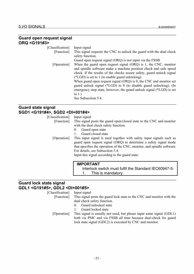
5.I/O SIGNALS B-63494EN/01
- 52 -
Guard open request signalORQ <G191#3>
[Classification] Input signal[Function] This signal requests the CNC to unlock the guard with the dual check
safety function.Guard open request signal (ORQ) is not input via the FSSB.
[Operation] When the guard open request signal (ORQ) is 1, the CNC, monitorand spindle software make a machine position check and safe speedcheck. If the results of the checks assure safety, guard unlock signal(*LGD) is set to 1 (to enable guard unlocking).When guard open request signal (ORQ) is 0, the CNC and monitor setguard unlock signal (*LGD) to 0 (to disable guard unlocking). (Inemergency stop state, however, the guard unlock signal (*LGD) is setto 1.)See Subsection 5.4.
Guard state signalSGD1 <G191#4>, SGD2 <DI+001#4>
[Classification] Input signal[Function] This signal posts the guard open/closed state to the CNC and monitor
with the dual check safety function.0: Guard open state1: Guard closed state
[Operation] This input signal is used together with safety input signals such asguard open request signal (ORQ) to determine a safety signal modethat specifies the operation of the CNC, monitor, and spindle software.For details, see Subsection 5.4.Input this signal according to the guard state.
IMPORTANTInterlock switch must fulfil the Standard IEC60947-5-1. This is mandatory.
Guard lock state signalGDL1 <G191#5>, GDL2 <DI+001#5>
[Classification] Input signal[Function] This signal posts the guard lock state to the CNC and monitor with the
dual check safety function.0: Guard unlocked state1: Guard locked state
[Operation] This signal is usually not used, but please input same signal (GDL1)both via PMC and via FSSB all time because dual-check for guardlock state signal (GDL2) is executed by CNC and monitor.
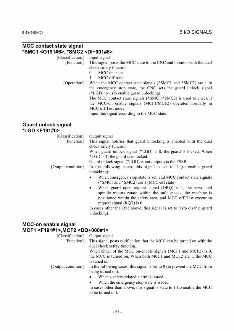
B-63494EN/01 5.I/O SIGNALS
- 53 -
MCC contact state signal*SMC1 <G191#6>, *SMC2 <DI+001#6>
[Classification] Input signal[Function] This signal posts the MCC state to the CNC and monitor with the dual
check safety function.0: MCC-on state1: MCC-off state
[Operation] When the MCC contact state signals (*SMC1 and *SMC2) are 1 inthe emergency stop state, the CNC sets the guard unlock signal(*LGD) to 1 (to enable guard unlocking).The MCC contact state signals (*SMC1/*SMC2) is used to check ifthe MCC-on enable signals (MCF1/MCF2) operates normally inMCC off Test mode.Input this signal according to the MCC state.
Guard unlock signal*LGD <F191#0>
[Classification] Output signal[Function] This signal notifies that guard unlocking is enabled with the dual
check safety function.When guard unlock signal (*LGD) is 0, the guard is locked. When*LGD is 1, the guard is unlocked.Guard unlock signal (*LGD) is not output via the FSSB.
[Output condition] In the following cases, this signal is set to 1 (to enable guardunlocking):• When emergency stop state is set, and MCC contact state signals
(*SMC1 and *SMC2) are 1 (MCC-off state)• When guard open request signal (ORQ) is 1, the servo and
spindle motors rotate within the safe speeds, the machine ispositioned within the safety area, and MCC off Test executionrequest signal (RQT) is 0
In cases other than the above, this signal is set to 0 (to disable guardunlocking).
MCC-on enable signalMCF1 <F191#1>,MCF2 <DO+000#1>
[Classification] Output signal[Function] This signal posts notification that the MCC can be turned on with the
dual check safety function.When either of the MCC on-enable signals (MCF1 and MCF2) is 0,the MCC is turned on. When both MCF1 and MCF2 are 1, the MCCis tuned on.
[Output condition] In the following cases, this signal is set to 0 (to prevent the MCC frombeing turned on):• When a safety-related alarm is issued• When the emergency stop state is issuedIn cases other than above, this signal is state to 1 (to enable the MCCto be turned on).
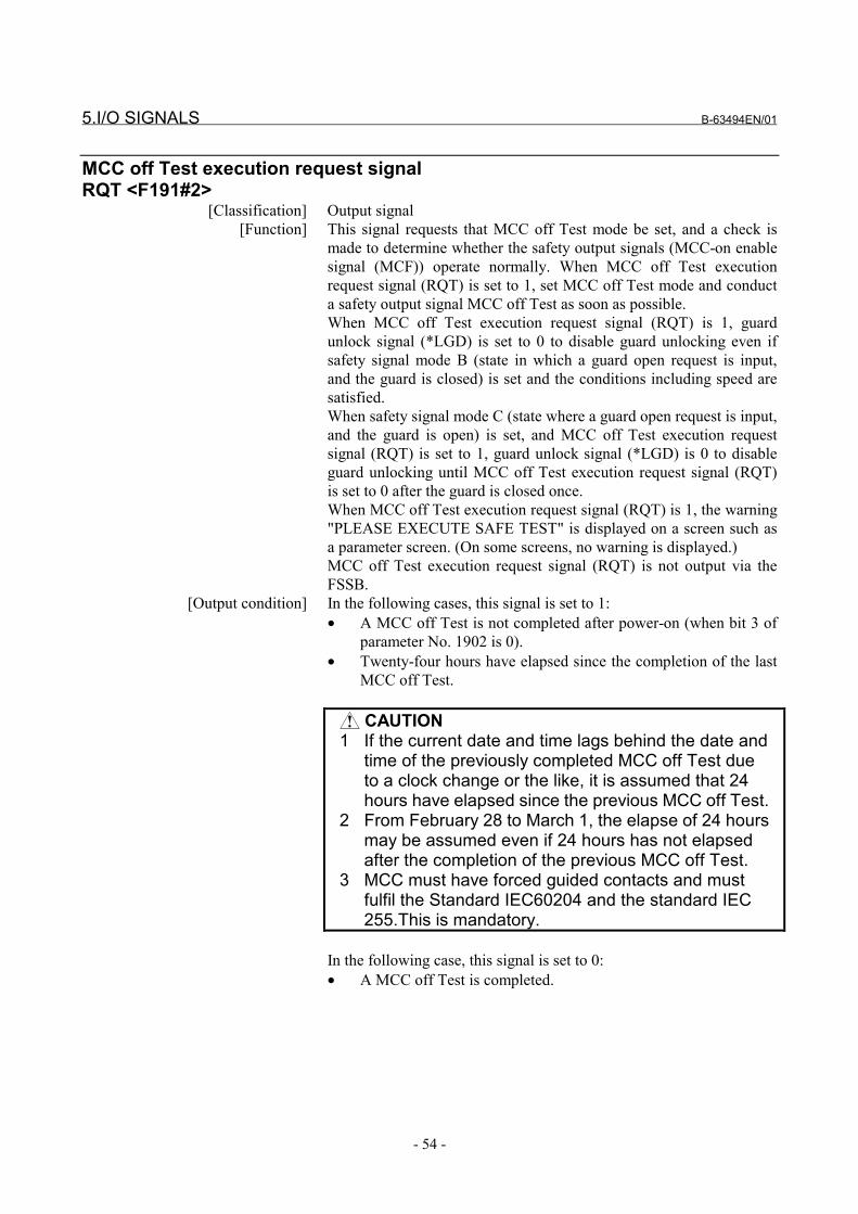
5.I/O SIGNALS B-63494EN/01
- 54 -
MCC off Test execution request signalRQT <F191#2>
[Classification] Output signal[Function] This signal requests that MCC off Test mode be set, and a check is
made to determine whether the safety output signals (MCC-on enablesignal (MCF)) operate normally. When MCC off Test executionrequest signal (RQT) is set to 1, set MCC off Test mode and conducta safety output signal MCC off Test as soon as possible.When MCC off Test execution request signal (RQT) is 1, guardunlock signal (*LGD) is set to 0 to disable guard unlocking even ifsafety signal mode B (state in which a guard open request is input,and the guard is closed) is set and the conditions including speed aresatisfied.When safety signal mode C (state where a guard open request is input,and the guard is open) is set, and MCC off Test execution requestsignal (RQT) is set to 1, guard unlock signal (*LGD) is 0 to disableguard unlocking until MCC off Test execution request signal (RQT)is set to 0 after the guard is closed once.When MCC off Test execution request signal (RQT) is 1, the warning"PLEASE EXECUTE SAFE TEST" is displayed on a screen such asa parameter screen. (On some screens, no warning is displayed.)MCC off Test execution request signal (RQT) is not output via theFSSB.
[Output condition] In the following cases, this signal is set to 1:• A MCC off Test is not completed after power-on (when bit 3 of
parameter No. 1902 is 0).• Twenty-four hours have elapsed since the completion of the last
MCC off Test.
CAUTION1 If the current date and time lags behind the date and
time of the previously completed MCC off Test dueto a clock change or the like, it is assumed that 24hours have elapsed since the previous MCC off Test.
2 From February 28 to March 1, the elapse of 24 hoursmay be assumed even if 24 hours has not elapsedafter the completion of the previous MCC off Test.
3 MCC must have forced guided contacts and mustfulfil the Standard IEC60204 and the standard IEC255.This is mandatory.
In the following case, this signal is set to 0:• A MCC off Test is completed.

B-63494EN/01 5.I/O SIGNALS
- 55 -
5.3 SIGNAL ADDRESSES
Via the PMC#7 #6 #5 #4 #3 #2 #1 #0
X008 *ESP1
(For loader control) #7 #6 #5 #4 #3 #2 #1 #0
X1000 *ESP1
#7 #6 #5 #4 #3 #2 #1 #0
G008 *ESPG
#7 #6 #5 #4 #3 #2 #1 #0
G191 *SMC1 GDL1 SGD1 ORQ OPT
#7 #6 #5 #4 #3 #2 #1 #0
F191 RQT MCF1 *LGD
Via the FSSB#7 #6 #5 #4 #3 #2 #1 #0
DI+0000 *ESP2
#7 #6 #5 #4 #3 #2 #1 #0
DI+001 *SMC2 GDL2 SGD2
#7 #6 #5 #4 #3 #2 #1 #0
DO+000 *BRK MCF2
CAUTION1 The signals of shaded boxes are duplexed.2 Emergency stop signals (*ESP) via the PMC
<X008#4> (<X1000#7> for loader control) and viathe FSSB <DI+000#0> are checked each other(dual-check for safety input signals), but *ESP viathe PMC <G008#4> is not checked.
3 *ESP1 (<X008#4> or <X1000#7> for loader control)is directly checked by the CNC. All signals via theFSSB are directly processed by the monitor CPU.None of the signals is processed by the PMC.
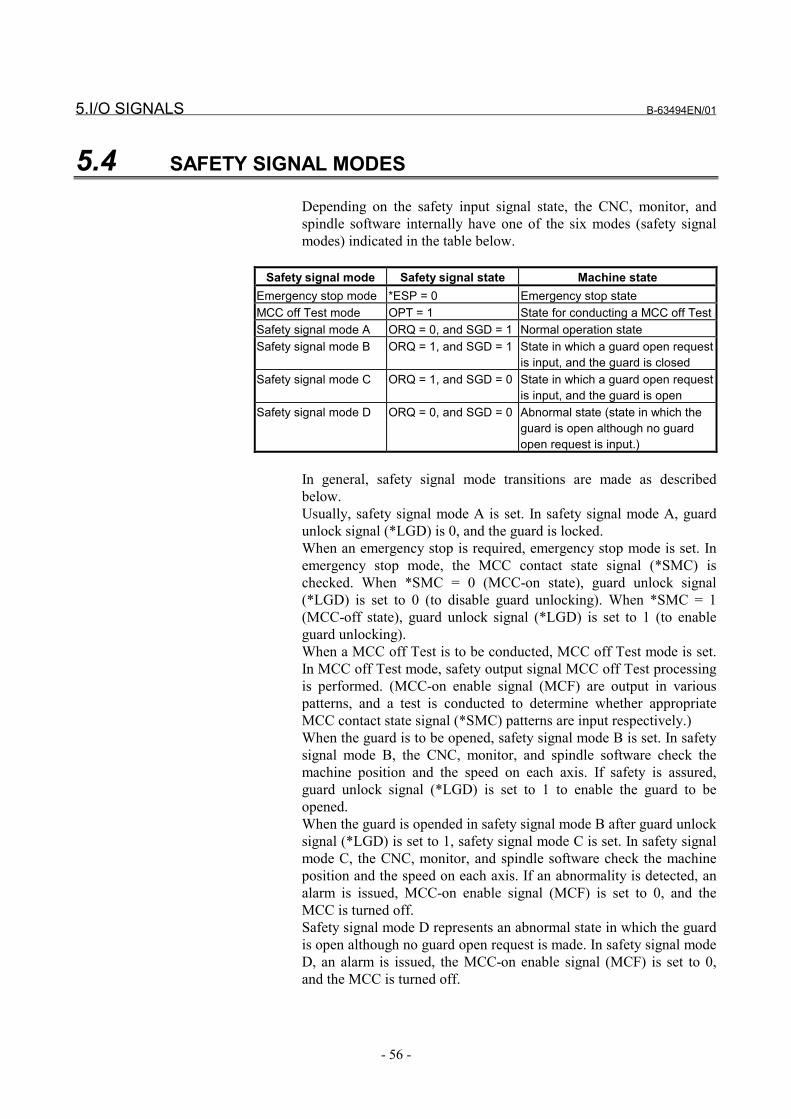
5.I/O SIGNALS B-63494EN/01
- 56 -
5.4 SAFETY SIGNAL MODES
Depending on the safety input signal state, the CNC, monitor, andspindle software internally have one of the six modes (safety signalmodes) indicated in the table below.
Safety signal mode Safety signal state Machine stateEmergency stop mode *ESP = 0 Emergency stop stateMCC off Test mode OPT = 1 State for conducting a MCC off TestSafety signal mode A ORQ = 0, and SGD = 1 Normal operation stateSafety signal mode B ORQ = 1, and SGD = 1 State in which a guard open request
is input, and the guard is closedSafety signal mode C ORQ = 1, and SGD = 0 State in which a guard open request
is input, and the guard is openSafety signal mode D ORQ = 0, and SGD = 0 Abnormal state (state in which the
guard is open although no guardopen request is input.)
In general, safety signal mode transitions are made as describedbelow.Usually, safety signal mode A is set. In safety signal mode A, guardunlock signal (*LGD) is 0, and the guard is locked.When an emergency stop is required, emergency stop mode is set. Inemergency stop mode, the MCC contact state signal (*SMC) ischecked. When *SMC = 0 (MCC-on state), guard unlock signal(*LGD) is set to 0 (to disable guard unlocking). When *SMC = 1(MCC-off state), guard unlock signal (*LGD) is set to 1 (to enableguard unlocking).When a MCC off Test is to be conducted, MCC off Test mode is set.In MCC off Test mode, safety output signal MCC off Test processingis performed. (MCC-on enable signal (MCF) are output in variouspatterns, and a test is conducted to determine whether appropriateMCC contact state signal (*SMC) patterns are input respectively.)When the guard is to be opened, safety signal mode B is set. In safetysignal mode B, the CNC, monitor, and spindle software check themachine position and the speed on each axis. If safety is assured,guard unlock signal (*LGD) is set to 1 to enable the guard to beopened.When the guard is opended in safety signal mode B after guard unlocksignal (*LGD) is set to 1, safety signal mode C is set. In safety signalmode C, the CNC, monitor, and spindle software check the machineposition and the speed on each axis. If an abnormality is detected, analarm is issued, MCC-on enable signal (MCF) is set to 0, and theMCC is turned off.Safety signal mode D represents an abnormal state in which the guardis open although no guard open request is made. In safety signal modeD, an alarm is issued, the MCC-on enable signal (MCF) is set to 0,and the MCC is turned off.

B-63494EN/01 5.I/O SIGNALS
- 57 -
5.5 NOTES ON MULTI-PATH CONTROL
This section describes cautions about safe-related I/O signals thatshould be taken in multi-path control.
5.5.1 Two-CPU Two-Path Control (Without Axis Change betweenPaths)
If there is no axis change between paths under two-CPU two-pathcontrol, a single independent group of safety areas can be providedfor each path (two groups of safety areas in total). Two FSSB I/Ounits, that is one unit for each path, are required. (The two FSSB I/Ounits are required even if just one group of safety areas is provided.)Two groups of safety input signals are cross-checked. The first groupconsists of a safety signal input to tool post 1 (DI1C: X008#4, G191 inthe figure below) and a safety signal input to the FSSB I/O unitconnected to tool post 1 (DI1M). The second group consists of a safetysignal input to tool post 2 (DI2C: X008#4, G1191) and a safety signalinput to the FSSB I/O unit connected to tool post 2 (DI2M).Safety output signals should be provided to the safety areas, asfollows: Provide a safety signal output from tool post 1 (DO1C: F191)and a safety signal output from the FSSB I/O unit connected to toolpost 1 (DO1M) to the safety area of tool post 1; Provide a safety signaloutput from tool post 2 (DO2C: F1191) and a safety signal output fromthe FSSB I/O unit connected to tool post 2 (DO2M) to the safety areaof tool post 2.
CNCCPU
MonitorCPU
Safety area 1 Guard MCC and so on
Safety area 1 Guard MCC and so on
cross-check
MAIN BOARD
CNCCPU
MonitorCPU
Safety area 2 Guard MCC and so on
Safety area 2 Guard MCC and so on
cross-check
SUB BOARD
Path 2Path 1
DI1M
DO1M
DI1C
DO1C
DI2M
DO2M
DI2C
DO2C

5.I/O SIGNALS B-63494EN/01
- 58 -
5.5.2 Two-CPU Two-Path Control (With Axis Change betweenPaths)
If there is an axis change between paths under two-CPU two-pathcontrol, a single group of safety areas can be provided. Two FSSB I/Ounits, that is one unit for each path, are required. (The two FSSB I/Ounits are required although just one group of safety areas is provided.)Two groups of safety input signals are cross-checked. The first groupconsists of a safety signal input to tool post 1 (DI1C: X008#4, G191)and a safety signal input to the FSSB I/O unit connected to tool post 1(DI1M). The second group consists of a safety signal input to tool post2 (DI2C: X008#4, G1191) and a safety signal input to the FSSB I/Ounit connected to tool post 2 (DI2M). Because just one group of safetyareas is provided, these four safety input signals (DI1C, DI1M, DI2C,and DI2M) should be equal.Safety output signals should be provided to the single group of safetyareas, as follows: Provide a safety signal output from tool post 1(DO1C: F191), safety signal output from tool post 2 (DO2C: F1191),safety signal output from the FSSB I/O unit connected to tool post 1(DO1M), and safety signal output from the FSSB I/O unit connected totool post 2 (DO2M) to the single group of safety areas.
CNCCPU
MonitorCPU
Safety area Guard MCC and so on
Safety area Guard MCC and so on
cross-check
MAIN BOARD
CNCCPU
MonitorCPU
cross-check
SUB BOARD
Path 1 Path 2
DI1M
DO1M
DI1C
DO1C
DI2M
DO2M
DI2C
DO2C
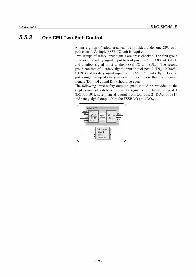
B-63494EN/01 5.I/O SIGNALS
- 59 -
5.5.3 One-CPU Two-Path Control
A single group of safety areas can be provided under one-CPU two-path control. A single FSSB I/O unit is required.Two groups of safety input signals are cross-checked. The first groupconsists of a safety signal input to tool post 1 (DI1C: X008#4, G191)and a safety signal input to the FSSB I/O unit (DIM). The secondgroup consists of a safety signal input to tool post 2 (DI2C: X008#4,G1191) and a safety signal input to the FSSB I/O unit (DIM). Becausejust a single group of safety areas is provided, these three safety inputsignals (DI1C, DI2C, and DIM) should be equal.The following three safety output signals should be provided to thesingle group of safety areas: safety signal output from tool post 1(DO1C: F191), safety signal output from tool post 2 (DO2C: F1191),and safety signal output from the FSSB I/O unit (DOM).
CNCCPU
MonitorCPU
Safety area Guard MCC and so on
Safety area Guard MCC and so on
cross-check
MAIN BOARD
Path 1
Path 2DIM
DOM
DI2C
DO1CDI1C
DO2C
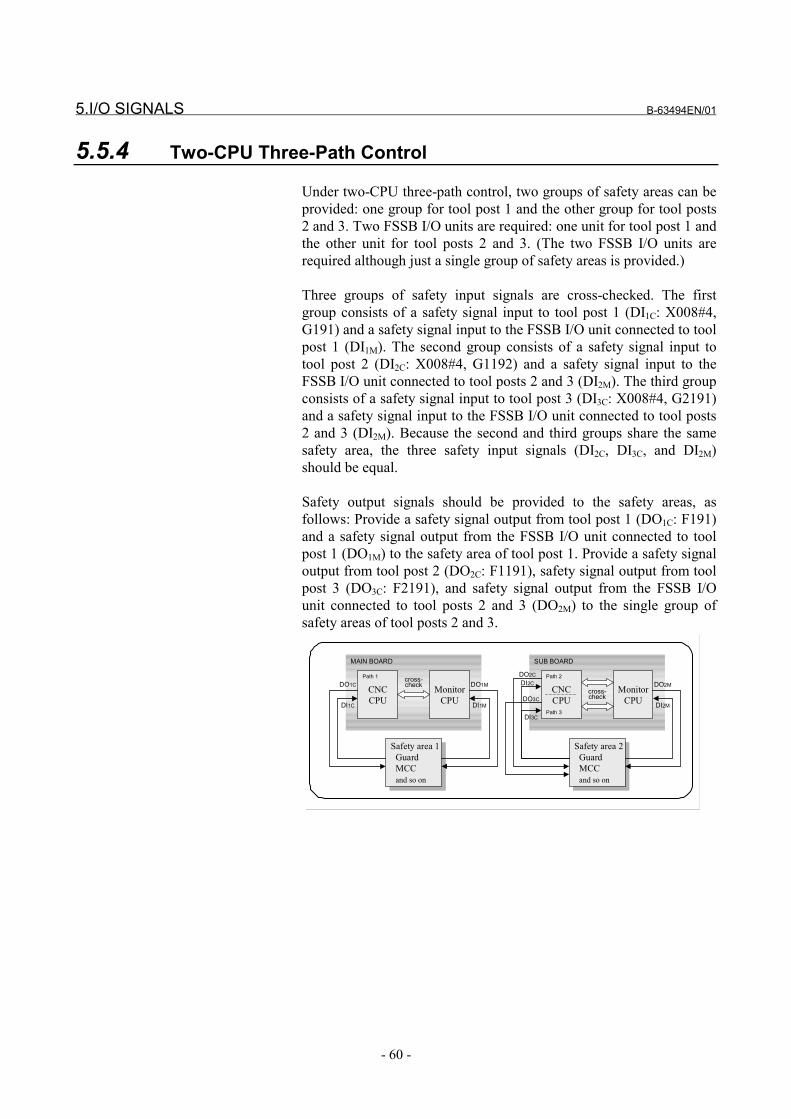
5.I/O SIGNALS B-63494EN/01
- 60 -
5.5.4 Two-CPU Three-Path Control
Under two-CPU three-path control, two groups of safety areas can beprovided: one group for tool post 1 and the other group for tool posts2 and 3. Two FSSB I/O units are required: one unit for tool post 1 andthe other unit for tool posts 2 and 3. (The two FSSB I/O units arerequired although just a single group of safety areas is provided.)
Three groups of safety input signals are cross-checked. The firstgroup consists of a safety signal input to tool post 1 (DI1C: X008#4,G191) and a safety signal input to the FSSB I/O unit connected to toolpost 1 (DI1M). The second group consists of a safety signal input totool post 2 (DI2C: X008#4, G1192) and a safety signal input to theFSSB I/O unit connected to tool posts 2 and 3 (DI2M). The third groupconsists of a safety signal input to tool post 3 (DI3C: X008#4, G2191)and a safety signal input to the FSSB I/O unit connected to tool posts2 and 3 (DI2M). Because the second and third groups share the samesafety area, the three safety input signals (DI2C, DI3C, and DI2M)should be equal.
Safety output signals should be provided to the safety areas, asfollows: Provide a safety signal output from tool post 1 (DO1C: F191)and a safety signal output from the FSSB I/O unit connected to toolpost 1 (DO1M) to the safety area of tool post 1. Provide a safety signaloutput from tool post 2 (DO2C: F1191), safety signal output from toolpost 3 (DO3C: F2191), and safety signal output from the FSSB I/Ounit connected to tool posts 2 and 3 (DO2M) to the single group ofsafety areas of tool posts 2 and 3.
CNCCPU
MonitorCPU
Safety area 1 Guard MCC and so on
Safety area 1 Guard MCC and so on
cross-check
MAIN BOARD
CNCCPU
MonitorCPU
Safety area 2 Guard MCC and so on
Safety area 2 Guard MCC and so on
cross-check
SUB BOARD
Path 2
Path 3
Path 1
DI1M
DO1M
DI1C
DO1C
DI2M
DO2M
DI3C
DO2CDI2C
DO3C
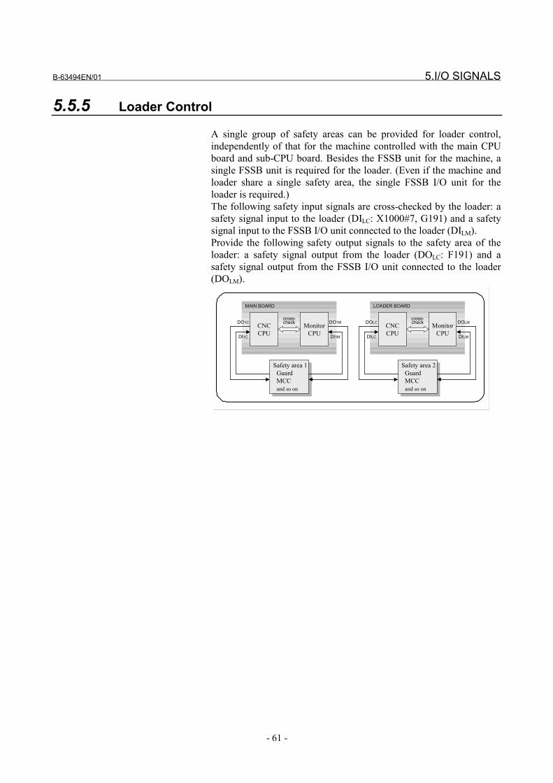
B-63494EN/01 5.I/O SIGNALS
- 61 -
5.5.5 Loader Control
A single group of safety areas can be provided for loader control,independently of that for the machine controlled with the main CPUboard and sub-CPU board. Besides the FSSB unit for the machine, asingle FSSB unit is required for the loader. (Even if the machine andloader share a single safety area, the single FSSB I/O unit for theloader is required.)The following safety input signals are cross-checked by the loader: asafety signal input to the loader (DILC: X1000#7, G191) and a safetysignal input to the FSSB I/O unit connected to the loader (DILM).Provide the following safety output signals to the safety area of theloader: a safety signal output from the loader (DOLC: F191) and asafety signal output from the FSSB I/O unit connected to the loader(DOLM).
CNCCPU
MonitorCPU
Safety area 1 Guard MCC and so on
Safety area 1 Guard MCC and so on
cross-check
MAIN BOARD
CNCCPU
MonitorCPU
Safety area 2 Guard MCC and so on
Safety area 2 Guard MCC and so on
cross-check
LOADER BOARD
DI1M
DO1M
DI1C
DO1C
DILM
DOLM
DILC
DOLC

6.PARAMETERS B-63494EN/01
- 62 -
6 PARAMETERS

B-63494EN/01 6.PARAMETERS
- 63 -
6.1 OVERVIEW
The parameters related to the dual check safety function (safetyparameters) are protected by a code (No. 3225) for the safetyparameters. The value of a safety parameter cannot be modifiedunless the same value as the code for the safety parameters is set asthe key (No. 3226) for the safety parameters.The safety parameters are stored in two locations on the CNC. TheCNC, monitor, and spindle software check the matching of theparameters stored at the two locations. If a mismatch is found, analarm is issued.
If the setting of a safety parameter is modified, the power must beturned off then back on. The new setting of the parameter becomeseffective after the power is turned back on.
For information about emergency stop mode, MCC off Test mode,and safety signal modes A/B/C/D described in this section, seeChapter 5.
Section 6.3 describes the parameters related to the use of the FSSBI/O unit.
Section 6.4 describes the functions that require special parametersettings.
6.PARAMETERS B-63494EN/01
- 64 -
6.2 PARAMETERS
1023 Servo axis number for each axis
[Data type] Byte axis[Valid data range] 1, 2, 3, ..., number of controlled axes
Set which servo axis corresponds to each controlled axis. Usually, setthe same value for a controlled axis number and servo axis number.A controlled axis number represents an array number for an axis typeparameter or axis type machine signal.For details of the setting, refer to the description of FSSB setting inthe connection manual (function part).
CAUTIONTo use the dual check safety function, the first servoaxis is required. To use the dual check safetyfunction under multi-path control, the first servo axiscannot be changed between paths. Specificrequirements are as follows.For one-path control, one-CPU two-path control,and loader control:
Tool post 1 (or loader) must have an axis forwhich parameter No.1023 is set to 1.
For two-CPU two-path control and two-CPU three-path control:
Tool post 1 must have an axis for whichparameter No.1023 is set to 1, and tool post 2must have an axis for which parameter No.1023is set to 9.
1829 Positional deviation limit during a stop for each axis
[Data type] Word axis[Unit of data] Detection unit
[Valid data range] 0 to 32767Set a positional deviation limit for each axis at stop time.If a positional deviation limit during a stop is exceeded at stop time, aservo alarm No.410 is issued, and an immediate stop (same as anemergency stop) is performed.In the dual check safety function, the CNC and monitor always checkthe position deviation amount on each axis. If the monitor detects thatthe position deviation limit is exceeded during a stop, a servo alarmNo.474 is issued only in safety signal mode C (state in which a guardopen request is input and the guard is open).

B-63494EN/01 6.PARAMETERS
- 65 -
1838 Positional deviation limit during movement for each axis in safety signal mode C
[Data type] 2-word axis[Unit of data] Detection unit
[Valid data range] 0 to 99999999Set a positional deviation limit during movement for each axis insafety signal mode C (state in which a guard open request is input,and the guard is opened) when the dual check safety function is used.If a positional deviation limit during movement is exceeded duringmovement, a servo alarm No.411 is issued, and an immediate stop(same as an emergency stop) is performed.In the dual check safety function, the CNC and monitor always checkthe position deviation amount on each axis. If the monitor detects thatthe position deviation limit is exceeded during moving, a servo alarmNo.475 is issued only in safety signal mode C (state in which a guardopen request is input and the guard is open).When the guard is open, axis movement is performed at a speed notexceeding the safe speed. So, usually, set a value smaller than apositional deviation limit during movement (parameter No. 1828).
#7 #6 #5 #4 #3 #2 #1 #0
1902 0 DCE 0 STP
[Data type] BitSTP When the power is turned on, a MCC off test is:
0: Conducted. (The warning "PLEASE EXECUTE MCC OFFTEST" is displayed at power-on, and MCC off Test executionrequest signal (RQT) is output.)
1: Not conducted.
CAUTION1 The STP parameter is used temporarily, for
example, when a MCC off Test is not to be made atpower-on as in the case of machine adjustment.Usually, set STP = 0.
2 Even when STP = 1, a MCC off Test is required if thepower is turned 24 hours or more after thecompletion of the previous MCC off Test.
WARNINGSet STP = 0 after the STP parameter is usedtemporarily as in the case of machine adjustment.
DCE The dual check safety function is:0: Disabled.1: Enabled.
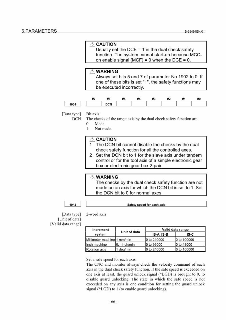
6.PARAMETERS B-63494EN/01
- 66 -
CAUTIONUsually set the DCE = 1 in the dual check safetyfunction. The system cannot start-up because MCC-on enable signal (MCF) = 0 when the DCE = 0.
WARNINGAlways set bits 5 and 7 of parameter No.1902 to 0. Ifone of these bits is set "1", the safety functions maybe executed incorrectly.
#7 #6 #5 #4 #3 #2 #1 #0
1904 DCN
[Data type] Bit axisDCN The checks of the target axis by the dual check safety function are:
0: Made.1: Not made.
CAUTION1 The DCN bit cannot disable the checks by the dual
check safety function for all the controlled axes.2 Set the DCN bit to 1 for the slave axis under tandem
control or for the tool axis of a simple electronic gearbox or electronic gear box 2-pair.
WARNINGThe checks by the dual check safety function are notmade on an axis for which the DCN bit is set to 1. Setthe DCN bit to 0 for normal axes.
1942 Safety speed for each axis
[Data type] 2-word axis[Unit of data]
[Valid data range]Valid data rangeIncrement
system Unit of dataIS-A, IS-B IS-C
Millimeter machine 1 mm/min 0 to 240000 0 to 100000Inch machine 0.1 inch/min 0 to 96000 0 to 48000Rotation axis 1 deg/min 0 to 240000 0 to 100000
Set a safe speed for each axis.The CNC and monitor always check the velocity command of eachaxis in the dual check safety function. If the safe speed is exceeded onone axis at least, the guard unlock signal (*LGD) is brought to 0, todisable guard unlocking. The state in which the safe speed is notexceeded on any axis is one condition for setting the guard unlocksignal (*LGD) to 1 (to enable guard unlocking).
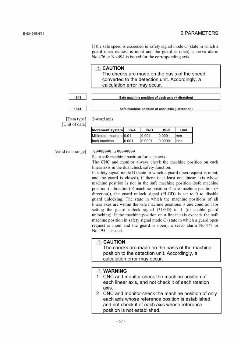
B-63494EN/01 6.PARAMETERS
- 67 -
If the safe speed is exceeded in safety signal mode C (state in which aguard open request is input and the guard is open), a servo alarmNo.476 or No.494 is issued for the corresponding axis.
CAUTIONThe checks are made on the basis of the speedconverted to the detection unit. Accordingly, acalculation error may occur.
1943 Safe machine position of each axis (+ direction)
1944 Safe machine position of each axis (- direction)
[Data type] 2-word axis[Unit of data]
Increment system IS-A IS-B IS-C UnitMillimeter machine 0.01 0.001 0.0001 mmInch machine 0.001 0.0001 0.00001 inch
[Valid data range] -99999999 to 99999999Set a safe machine position for each axis.The CNC and monitor always check the machine position on eachlinear axis in the dual check safety function.In safety signal mode B (state in which a guard open request is input,and the guard is closed), if there is at least one linear axis whosemachine position is not in the safe machine position (safe machineposition (- direction) ≤ machine position ≤ safe machine position (+direction)), the guard unlock signal (*LGD) is set to 0 to disableguard unlocking. The state in which the machine positions of alllinear axes are within the safe machine positions is one condition forsetting the guard unlock signal (*LGD) to 1 (to enable guardunlocking). If the machine position on a linear axis exceeds the safemachine position in safety signal mode C (state in which a guard openrequest is input and the guard is open), a servo alarm No.477 orNo.495 is issued.
CAUTIONThe checks are made on the basis of the machineposition to the detection unit. Accordingly, acalculation error may occur.
WARNING1 CNC and monitor check the machine position of
each linear axis, and not check it of each rotationaxis.
2 CNC and monitor check the machine position of onlyeach axis whose reference position is established,and not check it of each axis whose referenceposition is not established.

6.PARAMETERS B-63494EN/01
- 68 -
1945 Safety input signal check timer
[Data type] Word[Unit of data] ms
[Valid data range] 0 to 32767For input signals related to the dual check safety function (safetyinput signals), two paths are used: one path for input to the CNC viathe PMC, and the other for input to the monitor via the FSSB. TheCNC and monitor exchange the input signals with each other at alltimes to check each other. If a mismatch greater than the time set inthis parameter is detected between an input signal via one path andthe same signal via the other path, a servo alarm No.479 or No.486 isissued. If a value of less than 16 is specified, a specification of 16 msis assumed.
CAUTIONSet identical values in parameters No.1945 for thefollowing: two tool posts under two-CPU two-pathcontrol with axis change between paths, two toolposts under one-CPU two-path control, or tool posts2 and 3 under two-CPU three-path control.
1946 MCC off Test timer
[Data type] Word[Unit of data] ms
[Valid data range] 0 to 32767When MCC off Test mode is set with the dual check safety function,the CNC conducts a safety output signal MCC off Test. If a MCC offTest is not completed within the time set in this parameter, a servoalarm No.488 is issued.If a value of less than 0 is specified, a specification of 10000 ms isassumed.
1947 MCC-off timer 1
1948 MCC-off timer 2
[Data type] Word[Unit of data] ms
[Valid data range] 0 to 32767When the MCC-on enable signal (MCF) needs to be set to 0 (MCCoff) with the dual check safety function for a cause such as an alarmor emergency stop, the CNC and monitor set MCC-on enable signal(MCF) to 0 when an MCC-off timer value has elapsed after the alarmor emergency stop state.If a spindle alarm is issued, however, the timers are not used. Instead,MCC-on enable signal (MCF) is set to 0 immediately.If the MCC is cut off while the spindle motor is rotating, the spindlemotor will continue to rotate (free-run) and stop after time. When the
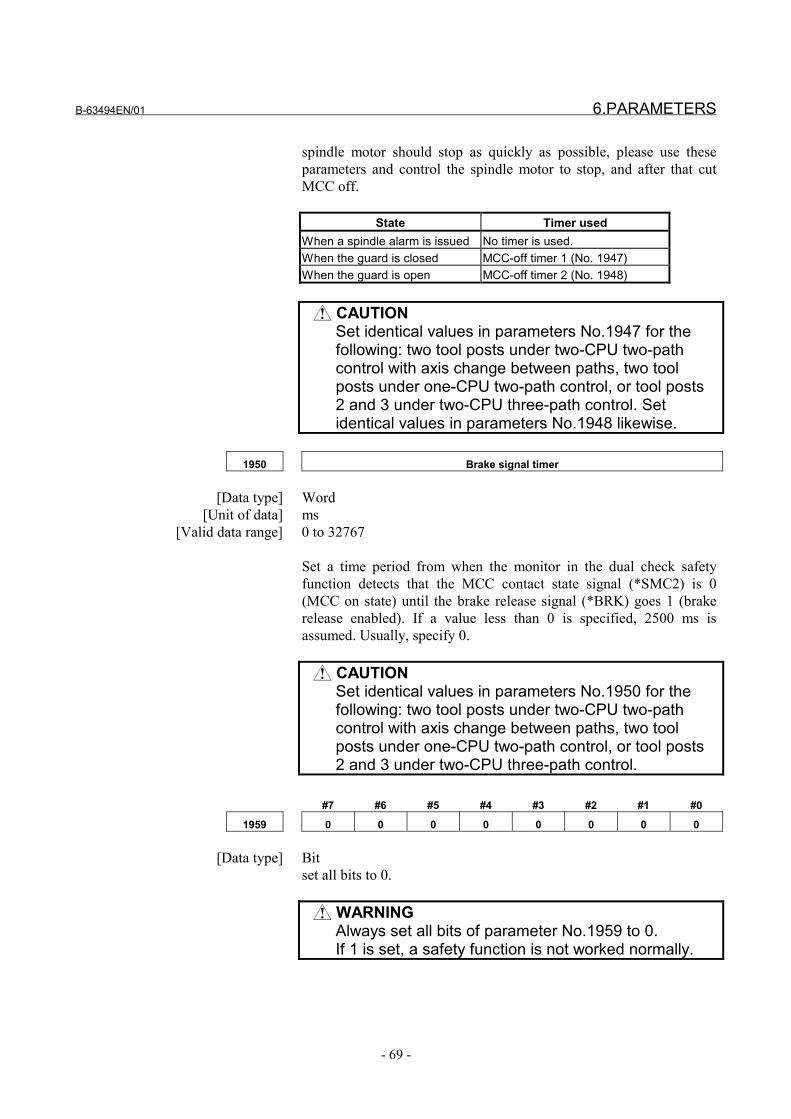
B-63494EN/01 6.PARAMETERS
- 69 -
spindle motor should stop as quickly as possible, please use theseparameters and control the spindle motor to stop, and after that cutMCC off.
State Timer usedWhen a spindle alarm is issued No timer is used.When the guard is closed MCC-off timer 1 (No. 1947)When the guard is open MCC-off timer 2 (No. 1948)
CAUTIONSet identical values in parameters No.1947 for thefollowing: two tool posts under two-CPU two-pathcontrol with axis change between paths, two toolposts under one-CPU two-path control, or tool posts2 and 3 under two-CPU three-path control. Setidentical values in parameters No.1948 likewise.
1950 Brake signal timer
[Data type] Word[Unit of data] ms
[Valid data range] 0 to 32767
Set a time period from when the monitor in the dual check safetyfunction detects that the MCC contact state signal (*SMC2) is 0(MCC on state) until the brake release signal (*BRK) goes 1 (brakerelease enabled). If a value less than 0 is specified, 2500 ms isassumed. Usually, specify 0.
CAUTIONSet identical values in parameters No.1950 for thefollowing: two tool posts under two-CPU two-pathcontrol with axis change between paths, two toolposts under one-CPU two-path control, or tool posts2 and 3 under two-CPU three-path control.
#7 #6 #5 #4 #3 #2 #1 #0
1959 0 0 0 0 0 0 0 0
[Data type] Bitset all bits to 0.
WARNINGAlways set all bits of parameter No.1959 to 0.If 1 is set, a safety function is not worked normally.
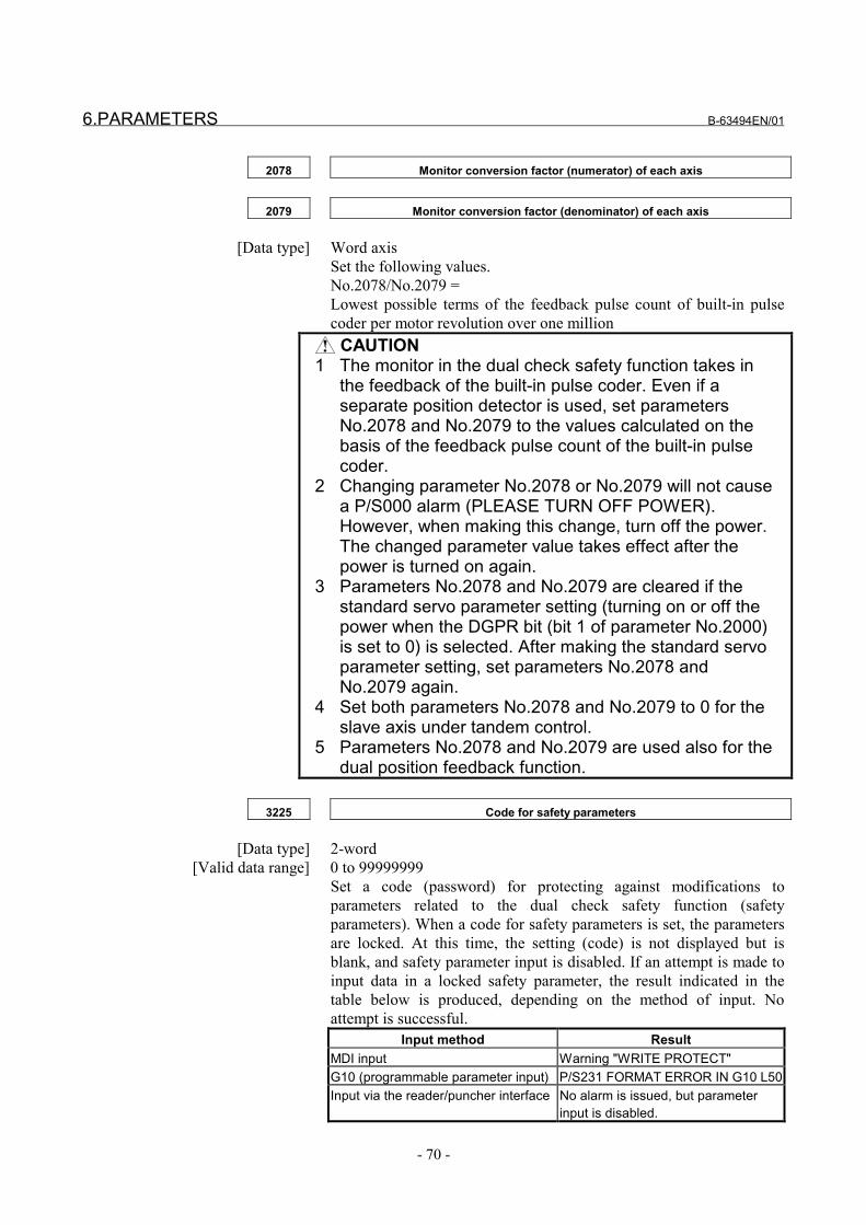
6.PARAMETERS B-63494EN/01
- 70 -
2078 Monitor conversion factor (numerator) of each axis
2079 Monitor conversion factor (denominator) of each axis
[Data type] Word axisSet the following values.No.2078/No.2079 =Lowest possible terms of the feedback pulse count of built-in pulsecoder per motor revolution over one million CAUTION
1 The monitor in the dual check safety function takes inthe feedback of the built-in pulse coder. Even if aseparate position detector is used, set parametersNo.2078 and No.2079 to the values calculated on thebasis of the feedback pulse count of the built-in pulsecoder.
2 Changing parameter No.2078 or No.2079 will not causea P/S000 alarm (PLEASE TURN OFF POWER).However, when making this change, turn off the power.The changed parameter value takes effect after thepower is turned on again.
3 Parameters No.2078 and No.2079 are cleared if thestandard servo parameter setting (turning on or off thepower when the DGPR bit (bit 1 of parameter No.2000)is set to 0) is selected. After making the standard servoparameter setting, set parameters No.2078 andNo.2079 again.
4 Set both parameters No.2078 and No.2079 to 0 for theslave axis under tandem control.
5 Parameters No.2078 and No.2079 are used also for thedual position feedback function.
3225 Code for safety parameters
[Data type] 2-word [Valid data range] 0 to 99999999
Set a code (password) for protecting against modifications toparameters related to the dual check safety function (safetyparameters). When a code for safety parameters is set, the parametersare locked. At this time, the setting (code) is not displayed but isblank, and safety parameter input is disabled. If an attempt is made toinput data in a locked safety parameter, the result indicated in thetable below is produced, depending on the method of input. Noattempt is successful.
Input method ResultMDI input Warning "WRITE PROTECT"G10 (programmable parameter input) P/S231 FORMAT ERROR IN G10 L50Input via the reader/puncher interface No alarm is issued, but parameter
input is disabled.

B-63494EN/01 6.PARAMETERS
- 71 -
Input through a window Completion code 7 (write protect)
A code for safety parameters can be set when the safety parametersare not locked, that is, when the code for safety parameters is 0, orwhen the code for safety parameters is the same as the key for safetyparameters (No. 3226).The following safety parameters are protected by a code for safetyparameters:No.1023, No.1829, No.1838, No.1902#3, No.1902#5, No.1902 #6,No.1904#0, No.1904#1, No.1904#2, No.1904#3, No.1904#4,No.1904#5, No1904#6, No.1942, No.1943, No.1944, No.1945,No.1946, No.1947, No.1948, No.1950, No.1959, No.3225, No.4372
3226 Key for safety parameters
[Data type] 2-word[Valid data range] 0 to 99999999
When the same value as the code for safety parameters is set in thisparameter, the key is opened to enable modifications to the safetyparameters. The value set in this parameter is not displayed. When thepower is turned off, the value set in this parameter is cleared,resulting in the locked state.
CAUTIONOnce a key is set, the key must be cancelled ormemory must be cleared before the safetyparameters can be modified. Moreover, the code forthe safety parameters cannot be modified. Be carefulwhen setting a code for safety parameters.
4372 Safe speed of each spindle
[Data type] Word[Unit of data] min-1
[Valid data range] 0 to 32767Set a safe speed for each spindle in terms of motor speed.With the dual check safety function, the CNC and spindle softwarealways check the speed of each spindle motor.In safety signal mode B (state in which a guard open request is input,and the guard is closed), if there is at least one spindle whose speed isgreater than the safe speed, guard unlock signal (*LGD) is set to 0 todisable guard unlocking. The state in which the speeds of all spindlemotors are within the safe speeds is one condition for setting guardunlock signal (*LGD) to 1 (to enable guard unlocking).In safety signal mode C (state in which a guard open request is inputand the guard is open), if a spindle speed exceeds the safe speed, aspindle alarm No.757 (No.767) or AL-69 is issued for thecorresponding spindle.

6.PARAMETERS B-63494EN/01
- 72 -
6.3 PARAMETERS RELATED TO THE USE OF FSSB I/O UNIT
#7 #6 #5 #4 #3 #2 #1 #0
1902 FMD
[Data type] Bit
FMD The FSSB setting mode is:0: Automatic setting mode.1: Manual setting 2 mode.
CAUTIONWhen using the dual check safety function, set theFMD bit to 1, to select manual setting 2 mode.
#7 #6 #5 #4 #3 #2 #1 #0
1905 IO2 IO1
[Data type] Bit axisIO1 A first FSSB I/O unit is:
0: Not used.1: Used.
IO2 A second FSSB I/O unit is:0: Not used.1: Used.
CAUTION1 The FSSB I/O unit and separate detector interface
unit (pulse module) are handled as units of the sametype on the FSSB. The term "first unit" or "secondunit" used in the following description means that theunit is the first or second one when counteddisregarding the difference between the FSSB I/Ounit and separate detector interface unit. If oneFSSB I/O unit and one separate detector interfaceunit are connected and if the separate detectorinterface unit is closer to the CNC on the FSSB thanthe FSSB I/O unit, for instance, the FSSB I/O unit isreferred to as the "second unit."
2 The FSSB I/O unit is controlled on the first servoaxis. Set IO1 (or IO2) to 1 for an axis for whichparameter No.1023 is set to 1 (to 9 for tool post 2under two-CPU two-path control or two-CPU three-path control). For the other axes, set both IO1 andIO2 to 0.

B-63494EN/01 6.PARAMETERS
- 73 -
1910 Address conversion table value for slave 1 of FSSB channel 1 (ATR) :
1919 Address conversion table value for slave 10 of FSSB channel 1 (ATR)
1970 Address conversion table value for slave 1 of FSSB channel 2 (ATR) :
1979 Address conversion table value for slave 10 of FSSB channel 2 (ATR)
[Data type] Byte[Valid data range] 0 to 7, 16, 40, 48
Set the address conversion table values for slaves 1 to 10 of eachFSSB channel."Slave" is a generic term for the FSSB I/O unit, separate detectorinterface unit, and servo amplifier connected to the CNC by an FSSBoptical cable. The slaves are numbered 1 to 10 in ascending order ofdistance from the CNC. A two-axis amplifier has two slaves. A three-axis amplifier has three slaves.If a slave is a separate detector interface unit or FSSB I/O unit, set 16for the first unit and 48 for the second unit.
CAUTIONThe FSSB I/O unit and separate detector interfaceunit (pulse module) are handled as units of the sametype on the FSSB. The term "first unit" or "secondunit" used in the following description means that theunit is the first or second one when counteddisregarding the difference between the FSSB I/Ounit and separate detector interface unit. If oneFSSB I/O unit and one separate detector interfaceunit are connected and if the separate detectorinterface unit is closer to the CNC on the FSSB thanthe FSSB I/O unit, for instance, the FSSB I/O unit isreferred to as the "second unit."

6.PARAMETERS B-63494EN/01
- 74 -
6.4 FUNCTIONS THAT REQUIRE SPECIAL PARAMETERSETTINGS
6.4.1 Tandem Control
To use tandem control, set the following parameters.• Master axis
No special parameter settings are required.• Slave axis
No.1904#6(DCN)=1No.2078=0No.2079=0
6.4.2 Simple Electronic Gear Box and Electronic Gear Box 2-pair
To use a simple electronic gear box or electronic gear box 2-pair, setthe following parameters.• Workpiece axis
No special parameter settings are required.• Tool axis (EGB axis)
No.1904#6(DCN)=1
6.4.3 Multi-path Control
To use multi-path control, set the following parameters.• Two-CPU two-path control (without axis change between paths)
No special parameter settings are required.• Two-CPU two-path control (with axis change between paths)
No.1023The first servo axis cannot be changed between paths.Accordingly, set parameter No.1023 to 1 for the axis of toolpost 1 and to 9 for the axis of tool post 2.
No.1945, No.1947, No.1948, No.1950Set identical values for the two tool posts.
• One-CPU two-path controlNo.1023
Set parameter No.1023 to 1 for the axis of tool post 1.No.1945, No.1947, No.1948, No.1950
Set identical values for the two tool posts.• Two-CPU three-path control (No axis change can be made
between tool post 1 and tool post 2 or 3.)No.1023
Set parameter No.1023 to 9 for the axis of tool post 2.No.1945, No.1947, No.1948, No.1950
Set identical values for tool posts 2 and 3.• Loader control
No special parameter settings are required.

B-63494EN/01 7.START-UP
- 75 -
7 START-UP

7.START-UP B-63494EN/01
- 76 -
7.1 START-UP OPERATION
The machine tool builder has to do tests for insulation and protectivebonding. Testing must be performed according to Chapter 19.2 and19.3 of the standard IEC 60204-1 by an appropriately authorizedperson and recorded.
Continuity of the protective bonding circuitWhen the machine is installed and the electrical connections arecomplete, including those to the power supply, the continuity of theprotective bonding circuit can be verified by a loop impedance test inaccordance with 612.6.3 of IEC 60364-6-61. For further details,please refer to Chapter 19.2 of IEC 60204-1.
Insulation resistance testsThe insulation resistance measured at 500 V d.c. between the powercircuit conductors and the protective bonding circuit is to be not lessthan 1MΩ. For further details, please refer to Chapter 19.3 of IEC60204-1.
7.1.1 Acceptance Test and Report for Safety Functions
Acceptance test for Safety functionThe machine tool builder is to conduct a dual check safety functioncheck test during machine start-up operation.In this test, limits need to be exceeded to check that the dual checksafety function operates normally.
Acceptance reportA qualified person is to check each dual check safety function andrecord the test results in a check report.
MOTEWhen modifying dual check safety function data,conduct an additional check test on the modifieddual check safety function and record the test resultsin a check report.
Safe-related I/O monitoring testData cross-check operation is tested with the I/O device connectordetached.
MCC off Test checkThe test mode signal is used to check that a MCC off Test isconducted.Negative test:
Conduct a MCC off Test by disconnecting the MCC contactsignal (input). Check that an alarm is issued and the MCCremains to be shut off.
B-63494EN/01 7.START-UP
- 77 -
Safe speed monitoring testThis test checks that when the actual speed exceeds a speed limit,safety stop state is set by a stop response.
Safe machine position monitoring testA positional limit test is conducted by making many differentmovements.A positional limit is placed at the center of an axis, and the position ismoved at many different speeds in a rapid traverse mode. Thus, thedistance traveled on the axis until stop state is set by a stop responseis measured. The machine tool builder is to determine a safety limitstop position including a safety margin.
Data modificationThe user needs to enter the correct password before setting safetyparameters with the system. After a safety parameter is modified, acheck test needs to be conducted on the related safety function, andthe test results need to be recorded in a report.

7.START-UP B-63494EN/01
- 78 -
7.1.2 Start-up of the Dual Check Safety Function
7.1.2.1 Initial start-up
Main flowDisable dual checksafety functionMachine start-up
FSSB I/O setting Safety parameterinput
Step 1Initial stateFirst, check that the machine starts up normally when the dual checksafety function is disabled.
Preparation 1 Disable the dual checksafety function.
Bit 6 of PRM No. 1902 = 0
Preparation 2 Disable output (MCF), fromI/O, that indicates MCC isturned off.
Connect the relay fordriving based on I/O output
CAUTIONWhen the dual check safety function is disabled, theMCC on enable signal (MCF) is not output. So, makea connection to temporarily disable MCF. To enablethe dual check safety function, reset the temporaryconnection.
Step 2FSSB I/O settingMake the same settings as for the pulse module.Example: When a two-axis amplifier is set as slave 1, and FSSB I/Ounit is set as slave 2Make the settings indicated in the table below.
Parameter setting MeaningBit 0 of No. 1902 = 1 Manually sets the FSSB setting mode.Bit 4 of No. 1905 = 1 Uses the first FSSB I/O unit.No. 1910 = 0 Sets the value of parameter No. 1023 less 1
when the slave is an amplifierNo. 1911 = 1 Sets the value of parameter No. 1023 less 1
when the slave is an amplifierNo. 1912 = 16 16 when the slave is a FSSB I/O unitNos. 1913 to 1919 = 40 40 when there is no slave

B-63494EN/01 7.START-UP
- 79 -
Step 3Safety parameter inputEnable the dual check safety function, and enter the safetyparameters.
Preparation 1 Enable the dual check safetyfunction.
Bit 6 of PRM No. 1902= 1
Preparation 2 Enables output (MCF), from I/O,that indicates MCC is turned off. Enable I/O output.
Set the safety parameters indicated in the table below.Parameter
settingMeaning
1942 Safe speed on each axis1943 Safe machine position (+ direction) on each axis1944 Safe machine position (- direction) on each axis1945 Timer for safety input signal check1946 Timer for MCC off Test1947 Timer 1 for MCC off1948 Timer 2 for MCC off1838 Positional deviation limit value in mode C2078 Dual position feedback conversion coefficient (numerator)2079 Dual position feedback conversion coefficient (denominator)4372 Safe speed on each spindle
Step 4If alarm 478 or 496 occurs, set the bit 4 of parameter No.2212 to 1,and reset this bit to 0. Then turn off the power of the entire system(included servo amplifier).
Step 5Execution of general machine testsAxis and spindle optimizationDual check safety function adjustment (safe speed, safe machineposition)
Step 6Test for checking the safety functionCheck test execution and report creation
Step 7Parameter preservationSave all parameters including the safety parameters. The parametersare used to start up the series.
Step 8Set a password.A password is used to disable unauthorized persons from modifyingsafety parameters. Before safety parameters of the equipment forwhich a password (No. 3225) is set can be modified, the passwordvalue must be set as the keyword (No. 3226). Only those personsauthorized to conduct a check test should know the password value.
7.START-UP B-63494EN/01
- 80 -
7.1.2.2 Series start-up
The parameters for the safety monitoring function are transferredtogether with other parameters to the CNC as in the case of normalseries start-up. Perform a safety function check test in addition to thenormal start-up procedure.
7.1.3 Troubleshooting
Alarms related to the safety function are output on the ALARMscreen.Correct the cause of trouble according to the chapter describingalarms and messages in this manual. When a component related to thesafety function is to be replaced, an authorized person must conduct asafety function check test.

B-63494EN/01 8.MAINTENANCE
- 81 -
8 MAINTENANCE

8.MAINTENANCE B-63494EN/01
- 82 -
8.1 SAFETY PRECAUTIONS
This section describes the safety precautions related to the use ofCNC units. It is essential that these precautions be observed by usersto ensure the safe operation of machines equipped with a CNC unit(all descriptions in this section assume this configuration).CNC maintenance involves various dangers. CNC maintenance mustbe undertaken only by a qualified technician.Users must also observe the safety precautions related to the machine,as described in the relevant manual supplied by the machine toolbuilder.Before checking the operation of the machine, take time to becomefamiliar with the manuals provided by the machine tool builder andFANUC.
CAUTIONMaintenance on a live system requires carefulplanning, adherence to operating and maintenanceprocedures, and the appropriate permits andpermissions.These matters are the responsibility of theowner/operator of the system and are outside thescope of this document.
TRAININGFANUC Training Center provides versatile training course for theperson who is concerned with hardware and software installation,maintenance and operation. FANUC recommend studying andlearning how efficiently operate FANUC products.
QUALIFIED PERSONNELOnly qualified personnel should be allowed to specify, apply, install,commissioning, operate, maintain, or perform any other functionrelated to the products described in the product manuals. Examples ofsuch qualified persons are defined as follows:• System application and design engineers who are familiar with
the safety concepts of machine tool.• Installation, startup, and service personnel who are trained to
install and maintain such machine tool.• Operating personnel trained to operate machine tool and trained
on the specific safety issues and requirements of the particularequipment.

B-63494EN/01 8.MAINTENANCE
- 83 -
MAINTENANCE PARTS TO BE MAINTAINED PERIODICALLY
• Memory backup battery replacement
WARNINGWhen replacing the memory backup batteries, keep the power to themachine (CNC) turned on, and apply an emergency stop to themachine. Because this work is performed with the power on and thecabinet open, only those personnel who have received approved safetyand maintenance training may perform this work.When replacing the batteries, be careful not to touch the high-voltagecircuits (marked and fitted with an insulating cover).Touching the uncovered high-voltage circuits presents an extremelydangerous electric shock hazard.
NOTEThe CNC uses batteries to preserve the contents ofits memory, because it must retain data such asprograms, offsets, and parameters even whileexternal power is not applied.If the battery voltage drops, a low battery voltagealarm is displayed on the machine operator's panelor CRT screen.When a low battery voltage alarm is displayed,replace the batteries within a week. Otherwise, thecontents of the CNC's memory will be lost.To replace the battery, see the procedure describedin Section 2.10 of the maintenance manual B-63005EN.
WARNINGS RELATED TO CHECK OPERATION
WARNING1. When checking the operation of the machine with the cover
removed(1) The user's clothing could become caught in the spindle or
other components, thus presenting a danger of injury. Whenchecking the operation, stand away from the machine toensure that your clothing does not become tangled in thespindle or other components.
(2) When checking the operation, perform idle operationwithout workpiece. When a workpiece is mounted in themachine, a malfunction could cause the workpiece to bedropped or destroy the tool tip, possibly scatteringfragments throughout the area. This presents a seriousdanger of injury. Therefore, stand in a safe location whenchecking the operation.

8.MAINTENANCE B-63494EN/01
- 84 -
2. When checking the machine operation with the power magneticscabinet door opened.(1) The power magnetics cabinet has a high-voltage section
(carrying a mark). Never touch the high-voltage section.The high-voltage section presents a severe risk of electricshock. Before starting any check of the operation, confirmthat the cover is mounted on the high-voltage section. Whenthe high-voltage section itself must be checked, note thattouching a terminal presents a severe danger of electricshock.
(2) Within the power magnetics cabinet, internal units presentpotentially injurious corners and projections. Be carefulwhen working inside the power magnetics cabinet.
3. Never attempt to machine a workpiece without first checking theoperation of the machine.Before starting a production run, ensure that the machine isoperating correctly by performing a trial run using, for example,the single block, feedrate override, or machine lock function orby operating the machine with neither a tool nor workpiecemounted. Failure to confirm the correct operation of the machinemay result in the machine behaving unexpectedly, possiblycausing damage to the workpiece and/or machine itself, or injuryto the user.
4. Before operating the machine, thoroughly check the entered data.Operating the machine with incorrectly specified data may resultin the machine behaving unexpectedly, possibly causing damageto the workpiece and/or machine itself, or injury to the user.
5. Ensure that the specified feedrate is appropriate for the intendedoperation. Generally, for each machine, there is a maximumallowable feedrate. The appropriate feedrate varies with theintended operation. Refer to the manual provided with themachine to determine the maximum allowable feedrate. If amachine is run at other than the correct speed, it may behaveunexpectedly, possibly causing damage to the workpiece and/ormachine itself, or injury to the user.
6. When using a tool compensation function, thoroughly check thedirection and amount of compensation.Operating the machine with incorrectly specified data may resultin the machine behaving unexpectedly, possibly causing damageto the workpiece and/or machine itself, or injury to the user.
B-63494EN/01 8.MAINTENANCE
- 85 -
WARNINGS RELATED TO REPLACEMENT
WARNING1. Always turn off the power to the CNC and the main power to the
power magnetics cabinet. If only the power to the CNC is turnedoff, power may continue to be supplied to the serve section.In such a case, replacing a unit may damage the unit, while alsopresenting a danger of electric shock.
2. When a heavy unit is to be replaced, the task must be undertakenby two persons or more. If the replacement is attempted by onlyone person, the replacement unit could slip and fall, possiblycausing injury.
3. After the power is turned off, the servo amplifier and spindleamplifier may retain voltages for a while, such that there is adanger of electric shock even while the amplifier is turned off.Allow at least twenty minutes after turning off the power forthese residual voltages to dissipate.
4. When replacing a unit, ensure that the new unit has the sameparameter and other settings as the old unit. (For details, refer tothe manual provided with the machine.) Otherwise,unpredictable machine movement could damage the workpieceor the machine itself, and present a danger of injury.
5. After replacing a safety related unit such as encoder and I/Omodule, conduct a check test on the safety related and record thetest results in a check report.
WARNINGS RELATED TO PARAMETERS
WARNING1. When machining a workpiece for the first time after modifying a
parameter, close the machine cover. Never use the automaticoperation function immediately after such a modification.Instead, confirm normal machine operation by using functionssuch as the single block function, feedrate override function, andmachine lock function, or by operating the machine withoutmounting a tool and workpiece. If the machine is used beforeconfirming that it operates normally, the machine may moveunpredictably, possibly damaging the machine or workpiece, andpresenting a risk of injury.
2. The CNC and PMC parameters are set to their optimal values, sothat those parameters usually need not be modified. When aparameter must be modified for some reason, ensure that youfully understand the function of that parameter before attemptingto modify it. If a parameter is set incorrectly, the machine maymove unpredictably, possibly damaging the machine orworkpiece, and presenting a risk of injury.
8.MAINTENANCE B-63494EN/01
- 86 -
8.2 ALARMS AND MESSAGES
8.2.1 Overview
Alarms related to the dual check safety function cannot be cancelledby a reset. To cancel the alarms, turn off the power, remove thecauses of the alarms, then turn on the power again.
For information about emergency stop mode, MCC off Test mode,and safety signal modes A/B/C/D, see Chapter 5.
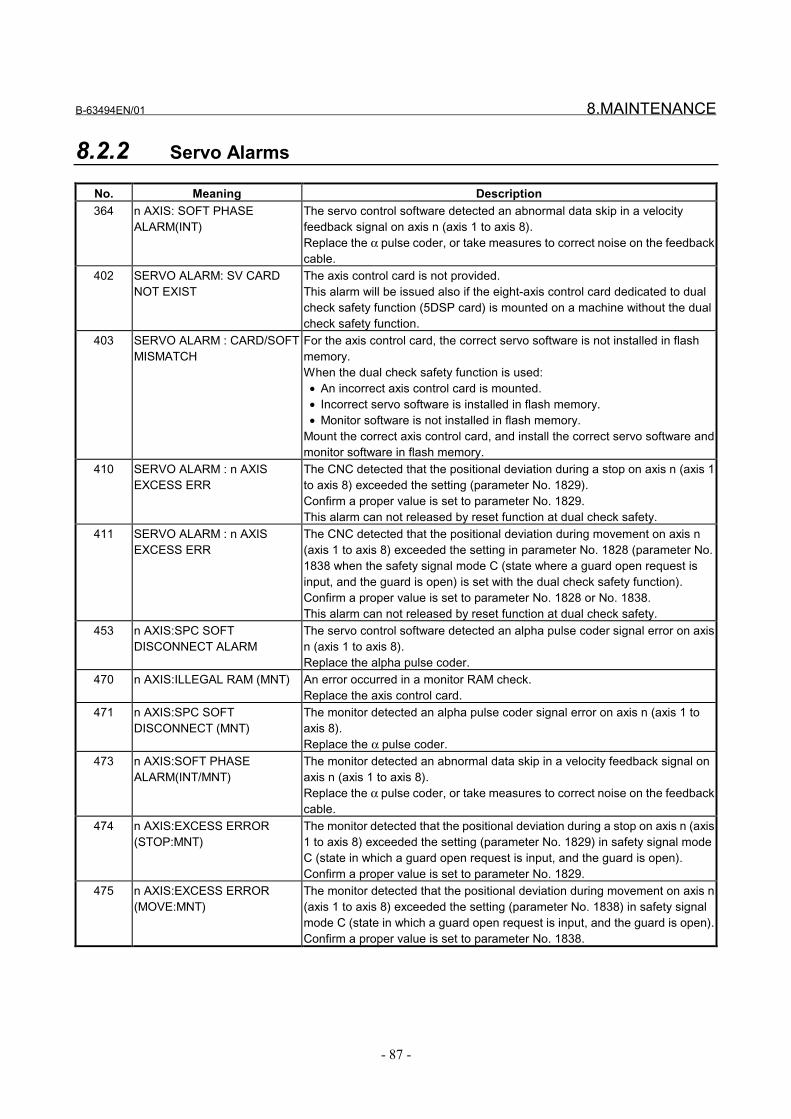
B-63494EN/01 8.MAINTENANCE
- 87 -
8.2.2 Servo Alarms
No. Meaning Description364 n AXIS: SOFT PHASE
ALARM(INT)The servo control software detected an abnormal data skip in a velocityfeedback signal on axis n (axis 1 to axis 8).Replace the α pulse coder, or take measures to correct noise on the feedbackcable.
402 SERVO ALARM: SV CARDNOT EXIST
The axis control card is not provided.This alarm will be issued also if the eight-axis control card dedicated to dualcheck safety function (5DSP card) is mounted on a machine without the dualcheck safety function.
403 SERVO ALARM : CARD/SOFTMISMATCH
For the axis control card, the correct servo software is not installed in flashmemory.When the dual check safety function is used: • An incorrect axis control card is mounted. • Incorrect servo software is installed in flash memory. • Monitor software is not installed in flash memory.Mount the correct axis control card, and install the correct servo software andmonitor software in flash memory.
410 SERVO ALARM : n AXISEXCESS ERR
The CNC detected that the positional deviation during a stop on axis n (axis 1to axis 8) exceeded the setting (parameter No. 1829).Confirm a proper value is set to parameter No. 1829.This alarm can not released by reset function at dual check safety.
411 SERVO ALARM : n AXISEXCESS ERR
The CNC detected that the positional deviation during movement on axis n(axis 1 to axis 8) exceeded the setting in parameter No. 1828 (parameter No.1838 when the safety signal mode C (state where a guard open request isinput, and the guard is open) is set with the dual check safety function).Confirm a proper value is set to parameter No. 1828 or No. 1838.This alarm can not released by reset function at dual check safety.
453 n AXIS:SPC SOFTDISCONNECT ALARM
The servo control software detected an alpha pulse coder signal error on axisn (axis 1 to axis 8).Replace the alpha pulse coder.
470 n AXIS:ILLEGAL RAM (MNT) An error occurred in a monitor RAM check.Replace the axis control card.
471 n AXIS:SPC SOFTDISCONNECT (MNT)
The monitor detected an alpha pulse coder signal error on axis n (axis 1 toaxis 8).Replace the α pulse coder.
473 n AXIS:SOFT PHASEALARM(INT/MNT)
The monitor detected an abnormal data skip in a velocity feedback signal onaxis n (axis 1 to axis 8).Replace the α pulse coder, or take measures to correct noise on the feedbackcable.
474 n AXIS:EXCESS ERROR(STOP:MNT)
The monitor detected that the positional deviation during a stop on axis n (axis1 to axis 8) exceeded the setting (parameter No. 1829) in safety signal modeC (state in which a guard open request is input, and the guard is open).Confirm a proper value is set to parameter No. 1829.
475 n AXIS:EXCESS ERROR(MOVE:MNT)
The monitor detected that the positional deviation during movement on axis n(axis 1 to axis 8) exceeded the setting (parameter No. 1838) in safety signalmode C (state in which a guard open request is input, and the guard is open).Confirm a proper value is set to parameter No. 1838.
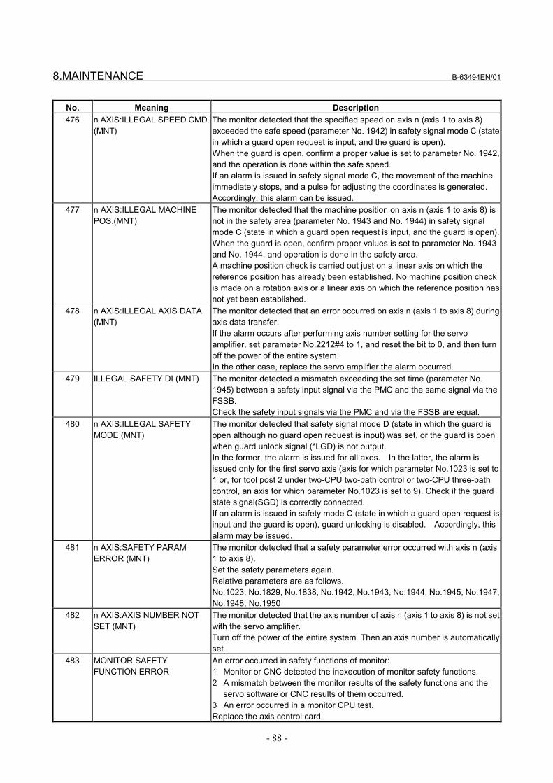
8.MAINTENANCE B-63494EN/01
- 88 -
No. Meaning Description476 n AXIS:ILLEGAL SPEED CMD.
(MNT)The monitor detected that the specified speed on axis n (axis 1 to axis 8)exceeded the safe speed (parameter No. 1942) in safety signal mode C (statein which a guard open request is input, and the guard is open).When the guard is open, confirm a proper value is set to parameter No. 1942,and the operation is done within the safe speed.If an alarm is issued in safety signal mode C, the movement of the machineimmediately stops, and a pulse for adjusting the coordinates is generated.Accordingly, this alarm can be issued.
477 n AXIS:ILLEGAL MACHINEPOS.(MNT)
The monitor detected that the machine position on axis n (axis 1 to axis 8) isnot in the safety area (parameter No. 1943 and No. 1944) in safety signalmode C (state in which a guard open request is input, and the guard is open).When the guard is open, confirm proper values is set to parameter No. 1943and No. 1944, and operation is done in the safety area.A machine position check is carried out just on a linear axis on which thereference position has already been established. No machine position checkis made on a rotation axis or a linear axis on which the reference position hasnot yet been established.
478 n AXIS:ILLEGAL AXIS DATA(MNT)
The monitor detected that an error occurred on axis n (axis 1 to axis 8) duringaxis data transfer.If the alarm occurs after performing axis number setting for the servoamplifier, set parameter No.2212#4 to 1, and reset the bit to 0, and then turnoff the power of the entire system.In the other case, replace the servo amplifier the alarm occurred.
479 ILLEGAL SAFETY DI (MNT) The monitor detected a mismatch exceeding the set time (parameter No.1945) between a safety input signal via the PMC and the same signal via theFSSB.Check the safety input signals via the PMC and via the FSSB are equal.
480 n AXIS:ILLEGAL SAFETYMODE (MNT)
The monitor detected that safety signal mode D (state in which the guard isopen although no guard open request is input) was set, or the guard is openwhen guard unlock signal (*LGD) is not output.In the former, the alarm is issued for all axes. In the latter, the alarm isissued only for the first servo axis (axis for which parameter No.1023 is set to1 or, for tool post 2 under two-CPU two-path control or two-CPU three-pathcontrol, an axis for which parameter No.1023 is set to 9). Check if the guardstate signal(SGD) is correctly connected.If an alarm is issued in safety mode C (state in which a guard open request isinput and the guard is open), guard unlocking is disabled. Accordingly, thisalarm may be issued.
481 n AXIS:SAFETY PARAMERROR (MNT)
The monitor detected that a safety parameter error occurred with axis n (axis1 to axis 8).Set the safety parameters again.Relative parameters are as follows.No.1023, No.1829, No.1838, No.1942, No.1943, No.1944, No.1945, No.1947,No.1948, No.1950
482 n AXIS:AXIS NUMBER NOTSET (MNT)
The monitor detected that the axis number of axis n (axis 1 to axis 8) is not setwith the servo amplifier.Turn off the power of the entire system. Then an axis number is automaticallyset.
483 MONITOR SAFETYFUNCTION ERROR
An error occurred in safety functions of monitor:1 Monitor or CNC detected the inexecution of monitor safety functions.2 A mismatch between the monitor results of the safety functions and the
servo software or CNC results of them occurred.3 An error occurred in a monitor CPU test.Replace the axis control card.
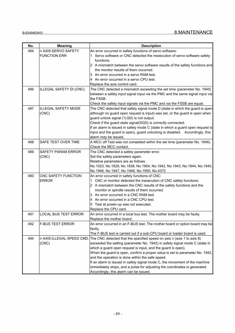
B-63494EN/01 8.MAINTENANCE
- 89 -
No. Meaning Description484 n AXIS:SERVO SAFETY
FUNCTION ERRAn error occurred in safety functions of servo software:1 Servo software or CNC detected the inexecution of servo software safety
functions.2 A mismatch between the servo software results of the safety functions and
the monitor results of them occurred.3 An error occurred in a servo RAM test.4 An error occurred in a servo CPU test.Replace the axis control card.
486 ILLEGAL SAFETY DI (CNC) The CNC detected a mismatch exceeding the set time (parameter No. 1945)between a safety input signal input via the PMC and the same signal input viathe FSSB.Check the safety input signals via the PMC and via the FSSB are equal.
487 ILLEGAL SAFETY MODE(CNC)
The CNC detected that safety signal mode D (state in which the guard is openalthough no guard open request is input) was set, or the guard is open whenguard unlock signal (*LGD) is not output.Check if the guard state signal(SGD) is correctly connected.If an alarm is issued in safety mode C (state in which a guard open request isinput and the guard is open), guard unlocking is disabled. Accordingly, thisalarm may be issued.
488 SAFE TEST OVER TIME A MCC off Test was not completed within the set time (parameter No. 1946).Check the MCC contact.
489 SAFETY PARAM ERROR(CNC)
The CNC detected a safety parameter error.Set the safety parameters again.Relative parameters are as follows.No.1023, No.1829, No.1838, No.1904, No.1942, No.1943, No.1944, No.1945,No.1946, No.1947, No.1948, No.1950, No.4372
490 CNC SAFETY FUNCTIONERROR
An error occurred in safety functions of CNC:1 CNC or monitor detected the inexecution of CNC safety functions.2 A mismatch between the CNC results of the safety functions and the
monitor or spindle results of them occurred.3 An error occurred in a CNC RAM test.4 An error occurred in a CNC CPU test.5 Test at power-up was not executed.Replace the CPU card.
491 LOCAL BUS TEST ERROR An error occurred in a local bus test. The mother board may be faulty.Replace the mother board.
492 F-BUS TEST ERROR An error occurred in an F-BUS test. The mother board or option board may befaulty.The F-BUS test is carried out if a sub-CPU board or loader board is used.
494 n AXIS:ILLEGAL SPEED CMD.(CNC)
The CNC detected that the specified speed on axis n (axis 1 to axis 8)exceeded the setting (parameter No. 1942) in safety signal mode C (state inwhich a guard open request is input, and the guard is open).When the guard is open, confirm a proper value is set to parameter No. 1942,and the operation is done within the safe speed.If an alarm is issued in safety signal mode C, the movement of the machineimmediately stops, and a pulse for adjusting the coordinates is generated.Accordingly, this alarm can be issued.
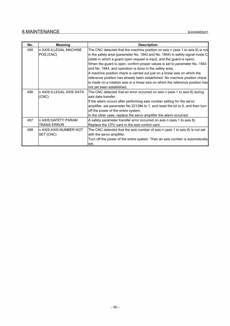
8.MAINTENANCE B-63494EN/01
- 90 -
No. Meaning Description495 n AXIS:ILLEGAL MACHINE
POS.(CNC)The CNC detected that the machine position on axis n (axis 1 to axis 8) is notin the safety area (parameter No. 1943 and No. 1944) in safety signal mode C(state in which a guard open request is input, and the guard is open).When the guard is open, confirm proper values is set to parameter No. 1943and No. 1944, and operation is done in the safety area.A machine position check is carried out just on a linear axis on which thereference position has already been established. No machine position checkis made on a rotation axis or a linear axis on which the reference position hasnot yet been established.
496 n AXIS:ILLEGAL AXIS DATA(CNC)
The CNC detected that an error occurred on axis n (axis 1 to axis 8) duringaxis data transfer.If the alarm occurs after performing axis number setting for the servoamplifier, set parameter No.2212#4 to 1, and reset the bit to 0, and then turnoff the power of the entire system.In the other case, replace the servo amplifier the alarm occurred.
497 n AXIS:SAFETY PARAMTRANS ERROR
A safety parameter transfer error occurred on axis n (axis 1 to axis 8).Replace the CPU card or the axis control card.
498 n AXIS:AXIS NUMBER NOTSET (CNC)
The CNC detected that the axis number of axis n (axis 1 to axis 8) is not setwith the servo amplifier.Turn off the power of the entire system. Then an axis number is automaticallyset.

B-63494EN/01 8.MAINTENANCE
- 91 -
8.2.3 Serial Spindle Alarms
No. Meaning Description749 S-SPINDLE LSI
ERRORIt is serial communication error while system is executing after power supply on.Check optical cable connection between main CPU board and spindle amplifier printedboard.Replace optical cable, main CPU board, option 2 board or spindle amplifier printedboard.If this alarm occurs when CNC power supply is turned on or when this alarm can not becleared even if CNC is reset, turn off the power supply also turn off the power supply inspindle side.
755 SPINDLE-1 SAFETYFUNCTION ERROR
An error occurred in any spindle safety functions on the first spindle.1 CNC detected that some spindle safety functions were not executed.2 A safety parameter transfer error occurred.Replace the CPU card or spindle amplifier module.
756 SPINDLE-1 ILLEGALAXIS DATA
For the first spindle, the CNC detected a mismatch between the spindle amplifierconnection state and spindle amplifier hardware setting.Check the spindle amplifier connection state and spindle amplifier hardware setting.Replace the CPU card or spindle amplifier module.If this alarm is issued because the spindle amplifier configuration is changed, correct thesetting on the spindle amplifier side.
757 SPINDLE-1 SAFETYSPEED OVER
For the first spindle, the CNC detected that the speed of the spindle motor exceeded thesafe speed (parameter No. 4372) in safety signal mode C (state in which a guard openrequest is input, and the guard is open).Alternatively, for the first spindle, the CNC detected a mismatch between the CNC andspindle software, as to which of the speed of the spindle motor and the safe speed(parameter No. 4372) is greater.When the guard is open, perform operation at a speed not exceeding the safe speed.Check the safe speed parameter(parameter No.4372).Replace the CPU card or spindle amplifier module.
765 SPINDLE-2 SAFETYFUNCTION ERROR
Same as alarm No. 755. (For the second spindle)
766 SPINDLE-2 ILLEGALAXIS DATA
Same as alarm No. 756. (For the second spindle)
767 SPINDLE-2 SAFETYSPEED OVER
Same as alarm No. 757. (For the second spindle)
7n16 SPN n :S-SPINDLEERROR (AL-16)
See the description of AL-16 in Subsection 8.2.4. (For the n-th spindle)
7n69 SPN n :S-SPINDLEERROR (AL-69)
See the description of AL-69 in Subsection 8.2.4. (For the n-th spindle)
7n70 SPN n :S-SPINDLEERROR (AL-69)
See the description of AL-70 in Subsection 8.2.4. (For the n-th spindle)
7n71 SPN n :S-SPINDLEERROR (AL-71)
See the description of AL-71 in Subsection 8.2.4. (For the n-th spindle)
7n72 SPN n :S-SPINDLEERROR (AL-72)
See the description of AL-72 in Subsection 8.2.4. (For the n-th spindle)
7n74 SPN n :S-SPINDLEERROR (AL-74)
See the description of AL-74 in Subsection 8.2.4. (For the n-th spindle)
7n76 SPN n :S-SPINDLEERROR (AL-76)
See the description of AL-76 in Subsection 8.2.4. (For the n-th spindle)
7n77 SPN n :S-SPINDLEERROR (AL-77)
See the description of AL-77 in Subsection 8.2.4. (For the n-th spindle)
7n78 SPN n :S-SPINDLEERROR (AL-78)
See the description of AL-78 in Subsection 8.2.4. (For the n-th spindle)

8.MAINTENANCE B-63494EN/01
- 92 -
8.2.4 Alarms Displayed on the Spindle Unit
No. Meaning DescriptionAL-16 RAM Alarm An error occurred in a spindle RAM test.
Replace spindle amplifier module.AL-69 Safety speed over The spindle software detected that the speed of the spindle motor exceeded the safe
speed (parameter No. 4372) in safety signal mode C (state in which a guard openrequest is input, and the guard is open).When the guard is open, perform operation at a speed not exceeding the safe speed.Check the safe speed parameter(parameter No.4372).Replace spindle amplifier module.
AL-70 Illegal axis data The spindle software detected a mismatch between the spindle amplifier connectionstate and spindle amplifier hardware setting.If this alarm is issued because the spindle amplifier configuration is changed, correct thesetting on the spindle amplifier side.Check the spindle amplifier connection state and spindle amplifier hardware setting.Replace the CPU card or spindle amplifier module.If this alarm is issued because the spindle amplifier configuration is changed, correct thesetting on the spindle amplifier side.
AL-71 Safety parameter error The spindle software detected a safety parameter error.Set the safety parameter again.Replace the CPU card or spindle amplifier module.Relative parameters are as follows.No.4372
AL-72 Mismatch the results ofmotor speed check
The spindle software detected a mismatch between the CNC result of the motor speedcheck and the spindle result of it.Replace the CPU card or spindle amplifier module.
AL-74 CPU test alarm An error occurred in a spindle amplifier CPU test.Replace spindle amplifier module.
AL-75 CRC alarm An error occurred in a spindle ROM CRC test.Replace spindle amplifier module.
AL-76 Inexecution of safetyfunctions
Any safety function was not executed.Replace spindle amplifier module.
AL-77 Mismatch the results ofaxis number check
The spindle software detected a mismatch between the CNC result of the axis numbercheck and the spindle result of it.Replace the CPU card or spindle amplifier module.
AL-78 Mismatch the results ofsafety parameterscheck
The spindle software detected a mismatch between the CNC result of the safetyparameters check and the spindle result of it.Replace the CPU card or spindle amplifier module.
AL-79 Inexecution of safetyfunctions at power-up
The safety functions at power-up for spindle were not executed. Replace the spindleamplifier.Replace spindle amplifier module.
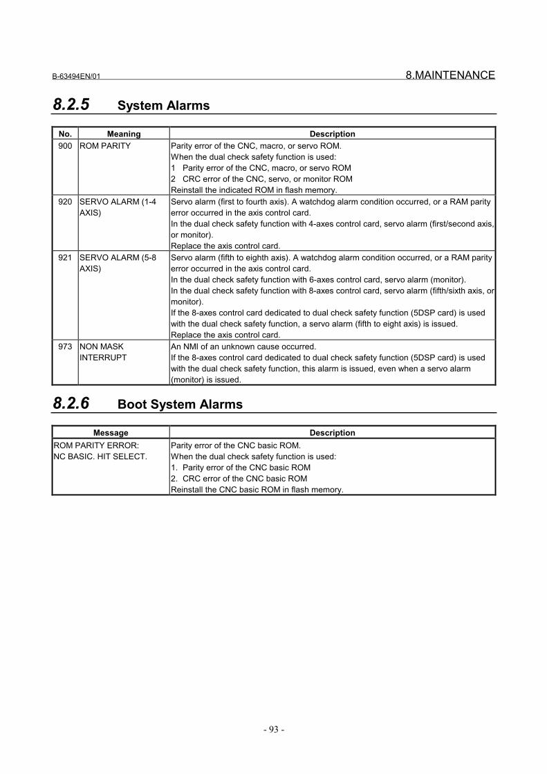
B-63494EN/01 8.MAINTENANCE
- 93 -
8.2.5 System Alarms
No. Meaning Description900 ROM PARITY Parity error of the CNC, macro, or servo ROM.
When the dual check safety function is used:1 Parity error of the CNC, macro, or servo ROM2 CRC error of the CNC, servo, or monitor ROMReinstall the indicated ROM in flash memory.
920 SERVO ALARM (1-4AXIS)
Servo alarm (first to fourth axis). A watchdog alarm condition occurred, or a RAM parityerror occurred in the axis control card.In the dual check safety function with 4-axes control card, servo alarm (first/second axis,or monitor).Replace the axis control card.
921 SERVO ALARM (5-8AXIS)
Servo alarm (fifth to eighth axis). A watchdog alarm condition occurred, or a RAM parityerror occurred in the axis control card.In the dual check safety function with 6-axes control card, servo alarm (monitor).In the dual check safety function with 8-axes control card, servo alarm (fifth/sixth axis, ormonitor).If the 8-axes control card dedicated to dual check safety function (5DSP card) is usedwith the dual check safety function, a servo alarm (fifth to eight axis) is issued.Replace the axis control card.
973 NON MASKINTERRUPT
An NMI of an unknown cause occurred.If the 8-axes control card dedicated to dual check safety function (5DSP card) is usedwith the dual check safety function, this alarm is issued, even when a servo alarm(monitor) is issued.
8.2.6 Boot System Alarms
Message DescriptionROM PARITY ERROR:NC BASIC. HIT SELECT.
Parity error of the CNC basic ROM.When the dual check safety function is used:1. Parity error of the CNC basic ROM2. CRC error of the CNC basic ROMReinstall the CNC basic ROM in flash memory.

9.DIAGNOSIS B-63494EN/01
- 94 -
9 DIAGNOSIS
B-63494EN/01 9.DIAGNOSIS
- 95 -
9.1 OVERVIEW
The information of safety signal mode and safety input signal of thedual check safety function is displayed.
For information about emergency stop mode, MCC off Test mode,and safety signal modes A/B/C/D, see Chapter 5.

9.DIAGNOSIS B-63494EN/01
- 96 -
9.2 DIAGNOSIS
#7 #6 #5 #4 #3 #2 #1 #0
Diagnosis No. 376 FMC FGL FGDThe current states of safety signals input via the FSSB are displayed.
FGD The state of the guard state signal (SGD2) is displayed.FGL The state of the guard lock state signal (GDL2) is displayed.FMC The state of the MCC contact state signal (*SMC2) is displayed.
#7 #6 #5 #4 #3 #2 #1 #0
Diagnosis No. 377 PMC PGL PGD PRQ PTSThe current states of safety signals input via the PMC are displayed.
PTS The state of the test mode signal (OPT) is displayed.PRQ The state of the guard open request signal (ORQ) is displayed.PGD The state of the guard state signal (SGD1) is displayed.PGL The state of the guard lock state signal (GDL1) is displayed.PMC The state of the MCC contact state signal (*SMC1) is displayed.
#7 #6 #5 #4 #3 #2 #1 #0
Diagnosis No. 378 ESP TST MDD MDC MDB MDAThe current safety signal mode is displayed.
MDA Safety signal mode AMDB Safety signal mode BMDC Safety signal mode CMDD Safety signal mode D
TST MCC off test modeESP Emergency stop mode
Diagnosis No. 379 Test number of MCC off testThe test number of the MCC off test is displayed.Zero is displayed if the system is not in the MCC off test mode.After the MCC off test mode is selected by the input of the test modesignal (OPT), the test number increases by 1 from 0 as the MCC offtest proceeds. When the MCC off test is completed, the test number is128. When the test mode signal (OPT) is set to 0 to clear the MCC offtest mode, the test number is cleared to 0.
B-63494EN/01 10.SAMPLE SYSTEM CONFIGURATION
- 97 -
10 SAMPLE SYSTEM CONFIGURATION

10.SAMPLE SYSTEM CONFIGURATION B-63494EN/01
- 98 -
10.1 SAMPLE CONFIGURATION
10.1.1 For One-path

B-63494EN/01 10.SAMPLE SYSTEM CONFIGURATION
- 99 -
10.1.2 For Two-path (When the main side and sub side use acommon MCC)

10.SAMPLE SYSTEM CONFIGURATION B-63494EN/01
- 100 -
10.1.3 For Two-path (When the main side and sub side useindependent MCCs and protection doors)

B-63494EN/01 10.SAMPLE SYSTEM CONFIGURATION
- 101 -
10.2 SAMPLE CONNECTIONS
10.2.1 Emergency Stop Signal (*ESP1, *ESP2)
*ESP1(X008#4)
I/O-Link I/O UNIT
*ESP2(DI+000#0)
FSSB I/O UNIT
+24V
CX4ESP
PSM0V
NOTESUse a two-contact emergency stop button with a forced dissociationmechanism.Connect the emergency stop button to the PSM, as illustrated in thefigure. When the signal is input, the spindle slows down and stops.Input a power-down factor to [G008#4] other than the signal from theemergency stop button.Create a Ladder program so that [X008#4] becomes a factor of[G008#4].
X00n#n
I/O-Link I/O UNIT PMC
LadderprogramEmergency stop factor
other than emergencystop button
Emergency stopfactor
Machine side
X008#4Emergencystop button
*ESPG(G008#4)

10.SAMPLE SYSTEM CONFIGURATION B-63494EN/01
- 102 -
10.2.2 Guard Open Request Signal (ORQ)
X00n#n
I/O-Link I/O UNIT+24VGuard openrequest button PMC
Ladder program
ORQ(G191#3)
NOTES• Create a Ladder program of conditions for making a guard open
request and then input the program to the PMC side [G191#3].• When the guard open request signal (ORQ) is input and when
CNC safety has been confirmed, the guard unlock signal (*LGD)is output. If the CNC is not safe, ORQ input will not result inoutput of *LGD.
• If the input of ORQ is canceled while the guard is open, the CNCenters a safely stopped status (state in which the guard is openalthough the guard open request signal is not input). Close theguard (SGD is set to 1), then cancel this signal.
10.2.3 Test Mode Signal (OPT)
X00n#n
I/O-Link I/O UNIT+24V
Test start button
PMC
Ladder program
OPT(G191#2)
NOTESCreate a Ladder program for performing a MCC off Test, then inputthe program to the PMC side [G191#2].

B-63494EN/01 10.SAMPLE SYSTEM CONFIGURATION
- 103 -
10.2.4 Guard Unlock Signal (*LGD), Guard Lock State Signal (GDL),Guard State Signal (SGD)
+24V
SW1 SW2
SW3
0V
0V
X00n#nI/O Link I/O UNIT
SGD(DI+001#4)
FSSB I/O UNIT
Y00n#n
PMCSGD(G191#4)
*LGD(F191#0)
Ladderprogram
RY1
RY2
RY1
RY2
RY3
RY3RY3
RY1 RY2
Guard-monitoringlimit switch
Safety relay
[Sample control components]SW1/SW2:
Guard state monitoringswitch with forceddissociation mechanism
SW3:Guard lock switch
RY1, RY2, RY3:Safety relay
Guard closed

10.SAMPLE SYSTEM CONFIGURATION B-63494EN/01
- 104 -
OPERATING PRINCIPLEThis section describes the operation of various guard monitoring limitswitches with lock mechanism and safety relays.State transition of components
SW1 SW2 SW3 RY1 RY2 RY3 SGD1 Guard closed
Guard lockedCLOSE CLOSE CLOSE ON ON OFF 1
2 Guard closedGuard unlocked
CLOSE CLOSE OPEN OFF ON OFF 0
3 Guard openedGuard unlocked
OPEN OPEN OPEN OFF OFF ON 0
In a normal operation, the transition of 1, 2, 3, 1, 2, and so on isrepeated.RY3 detects whether RY1 and RY2 contacts are made. If an unusualevent is detected, SGD input is turned off.
NOTESThis example does not use the guard lock state signal (GDL). If GDLis not used, as in this example, tie [G191#5] and [DI+001#5] to 1.The guard state is monitored, and the guard state signal (SGD) affectsthe dual check safety function. The guard lock state signal (GDL)only indicates whether an input mismatch is found. The state of theGDL signal does not affect the dual check safety function.The illustrated sample system determines that the guard is open (setsSGD to 0) when the guard is unlocked.When the guard open request signal (ORQ) is accepted and when ithas been confirmed that the CNC is in a safe state, the guard unlocksignal (*LGD) is output. Based on this signal, use a Ladder programto create a guard unlock signal.
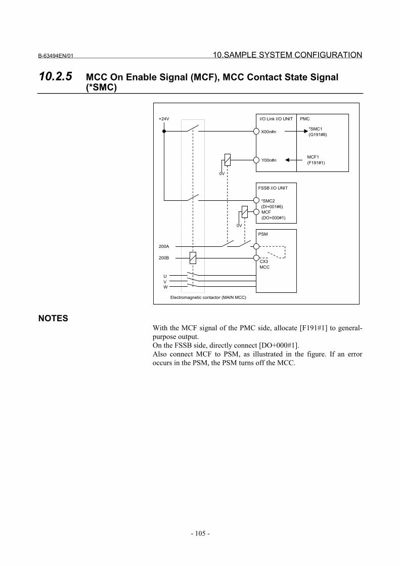
B-63494EN/01 10.SAMPLE SYSTEM CONFIGURATION
- 105 -
10.2.5 MCC On Enable Signal (MCF), MCC Contact State Signal(*SMC)
X00n#n
I/O Link I/O UNIT
FSSB I/O UNIT
Y00n#n
PMC
MCF1(F191#1)
*SMC2(DI+001#6)MCF(DO+000#1)
0V
PSM
+24V
200A
200B
UVW
0V
Electromagnetic contactor (MAIN MCC)
CX3MCC
*SMC1(G191#6)
NOTESWith the MCF signal of the PMC side, allocate [F191#1] to general-purpose output.On the FSSB side, directly connect [DO+000#1].Also connect MCF to PSM, as illustrated in the figure. If an erroroccurs in the PSM, the PSM turns off the MCC.

11.COMPONENTS LIST B-63494EN/01
- 106 -
11 COMPONENTS LIST

B-63494EN/01 11.COMPONENTS LIST
- 107 -
11.1 HARDWARE COMPONENTS
11.1.1 Hardware Components for Series16i/18i/21i/160i/180i/210i/160is/180is/210is-MODEL A
No. Description Specification numberOf primary component
Specification numberof secondary component Remarks
1 Main board A20B-8100-0130 A20B-8100-013XA20B-8100-054X
A20B-8100-014X
2 CPU card A20B-3300-0170 A20B-3300-0050A20B-3300-0260
A20B-3300-0070
3 Servo card A17B-3300-0200 A20B-3300-012XA20B-3300-024X
A20B-3300-020X
4 DRAM MODULE A20B-3900-0131 A20B-3900-003XA20B-3900-013X
A20B-3900-004X
5 SRAM MODULE A20B-3900-0060 A20B-3900-005XA20B-3900-002X
A20B-3900-006X
6 FROM MODULE A20B-3900-0011 A20B-3900-001X A20B-3900-007X
11.1.2 Hardware Components for Series16i/18i/21i/160i/180i/210i/160is/180is/210is-MODEL B
No. Description Specification numberOf primary component
Specification numberof secondary component Remarks
1 Main board A20B-8100-0660 A20B-8100-066XA20B-8100-079X
A16B-3200-042X
2 CPU card A20B-3300-0311 A20B-3300-031X A20B-3300-029X3 Servo card A20B-3300-0244
A17B-3300-0500A20B-3300-024X
4 FROM/SRAM MODULE A20B-3900-0160 A20B-3900-016XA20B-3900-018X
5 Power supply module A20B-8100-0720 A20B-8100-08516 Sub CPU board A20B-8002-0190 A16B-2203-07517 Loader control board A20B-8100-0830 A16B-2203-0740
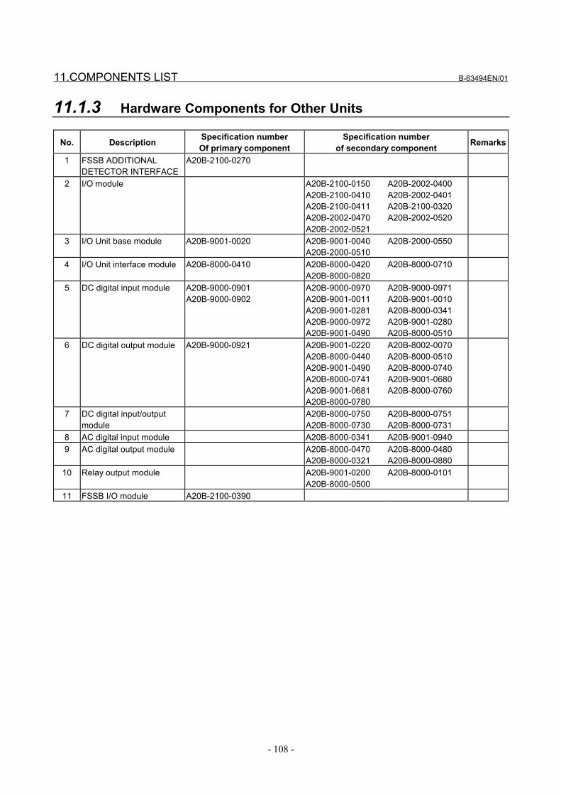
11.COMPONENTS LIST B-63494EN/01
- 108 -
11.1.3 Hardware Components for Other Units
No. Description Specification numberOf primary component
Specification numberof secondary component Remarks
1 FSSB ADDITIONALDETECTOR INTERFACE
A20B-2100-0270
2 I/O module A20B-2100-0150A20B-2100-0410A20B-2100-0411A20B-2002-0470A20B-2002-0521
A20B-2002-0400A20B-2002-0401A20B-2100-0320A20B-2002-0520
3 I/O Unit base module A20B-9001-0020 A20B-9001-0040A20B-2000-0510
A20B-2000-0550
4 I/O Unit interface module A20B-8000-0410 A20B-8000-0420A20B-8000-0820
A20B-8000-0710
5 DC digital input module A20B-9000-0901A20B-9000-0902
A20B-9000-0970A20B-9001-0011A20B-9001-0281A20B-9000-0972A20B-9001-0490
A20B-9000-0971A20B-9001-0010A20B-8000-0341A20B-9001-0280A20B-8000-0510
6 DC digital output module A20B-9000-0921 A20B-9001-0220A20B-8000-0440A20B-9001-0490A20B-8000-0741A20B-9001-0681A20B-8000-0780
A20B-8002-0070A20B-8000-0510A20B-8000-0740A20B-9001-0680A20B-8000-0760
7 DC digital input/outputmodule
A20B-8000-0750A20B-8000-0730
A20B-8000-0751A20B-8000-0731
8 AC digital input module A20B-8000-0341 A20B-9001-09409 AC digital output module A20B-8000-0470
A20B-8000-0321A20B-8000-0480A20B-8000-0880
10 Relay output module A20B-9001-0200A20B-8000-0500
A20B-8000-0101
11 FSSB I/O module A20B-2100-0390
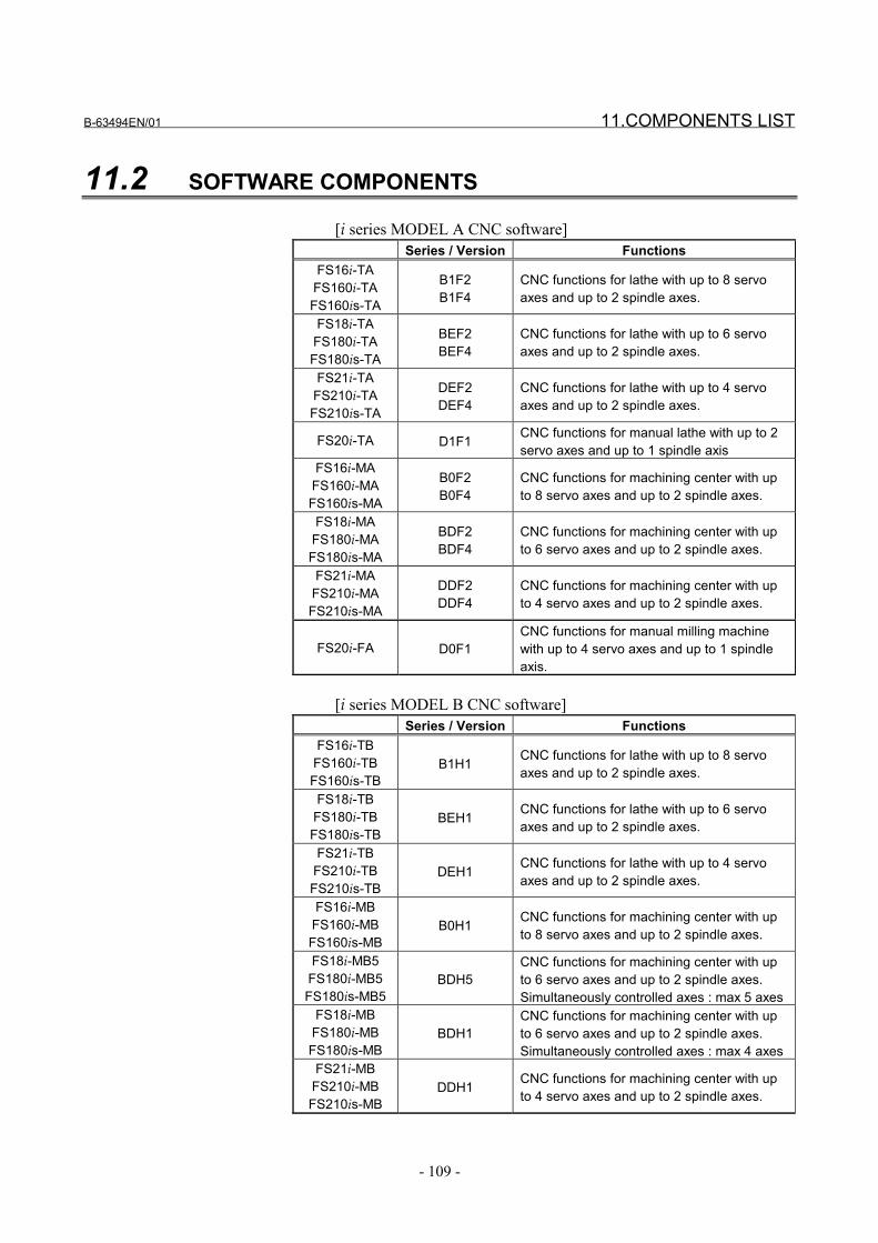
B-63494EN/01 11.COMPONENTS LIST
- 109 -
11.2 SOFTWARE COMPONENTS
[i series MODEL A CNC software]Series / Version Functions
FS16i-TAFS160i-TAFS160is-TA
B1F2B1F4
CNC functions for lathe with up to 8 servoaxes and up to 2 spindle axes.
FS18i-TAFS180i-TAFS180is-TA
BEF2BEF4
CNC functions for lathe with up to 6 servoaxes and up to 2 spindle axes.
FS21i-TAFS210i-TAFS210is-TA
DEF2DEF4
CNC functions for lathe with up to 4 servoaxes and up to 2 spindle axes.
FS20i-TA D1F1 CNC functions for manual lathe with up to 2servo axes and up to 1 spindle axis
FS16i-MAFS160i-MAFS160is-MA
B0F2B0F4
CNC functions for machining center with upto 8 servo axes and up to 2 spindle axes.
FS18i-MAFS180i-MAFS180is-MA
BDF2BDF4
CNC functions for machining center with upto 6 servo axes and up to 2 spindle axes.
FS21i-MAFS210i-MAFS210is-MA
DDF2DDF4
CNC functions for machining center with upto 4 servo axes and up to 2 spindle axes.
FS20i-FA D0F1CNC functions for manual milling machinewith up to 4 servo axes and up to 1 spindleaxis.
[i series MODEL B CNC software]Series / Version Functions
FS16i-TBFS160i-TBFS160is-TB
B1H1 CNC functions for lathe with up to 8 servoaxes and up to 2 spindle axes.
FS18i-TBFS180i-TBFS180is-TB
BEH1 CNC functions for lathe with up to 6 servoaxes and up to 2 spindle axes.
FS21i-TBFS210i-TBFS210is-TB
DEH1 CNC functions for lathe with up to 4 servoaxes and up to 2 spindle axes.
FS16i-MBFS160i-MBFS160is-MB
B0H1 CNC functions for machining center with upto 8 servo axes and up to 2 spindle axes.
FS18i-MB5FS180i-MB5FS180is-MB5
BDH5CNC functions for machining center with upto 6 servo axes and up to 2 spindle axes.Simultaneously controlled axes : max 5 axes
FS18i-MBFS180i-MBFS180is-MB
BDH1CNC functions for machining center with upto 6 servo axes and up to 2 spindle axes.Simultaneously controlled axes : max 4 axes
FS21i-MBFS210i-MBFS210is-MB
DDH1 CNC functions for machining center with upto 4 servo axes and up to 2 spindle axes.
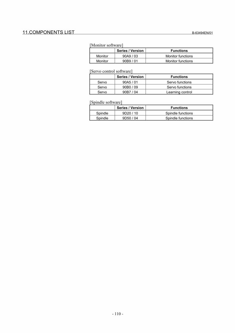
11.COMPONENTS LIST B-63494EN/01
- 110 -
[Monitor software]Series / Version Functions
Monitor 90A9 / 03 Monitor functionsMonitor 90B9 / 01 Monitor functions
[Servo control software]Series / Version Functions
Servo 90A5 / 01 Servo functionsServo 90B0 / 09 Servo functionsServo 90B7 / 04 Learning control
[Spindle software]Series / Version Functions
Spindle 9D20 / 10 Spindle functionsSpindle 9D50 / 04 Spindle functions
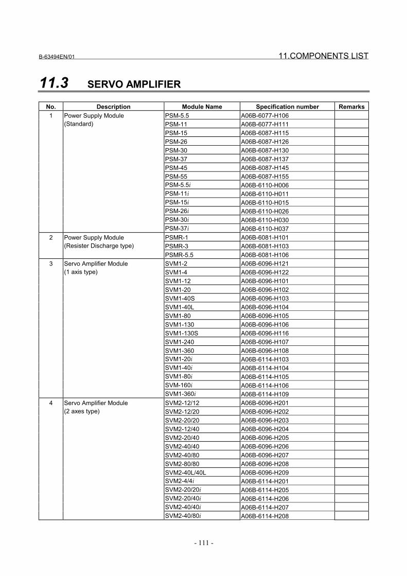
B-63494EN/01 11.COMPONENTS LIST
- 111 -
11.3 SERVO AMPLIFIER
No. Description Module Name Specification number RemarksPSM-5.5 A06B-6077-H106PSM-11 A06B-6077-H111PSM-15 A06B-6087-H115PSM-26 A06B-6087-H126PSM-30 A06B-6087-H130PSM-37 A06B-6087-H137PSM-45 A06B-6087-H145PSM-55 A06B-6087-H155PSM-5.5i A06B-6110-H006PSM-11i A06B-6110-H011PSM-15i A06B-6110-H015PSM-26i A06B-6110-H026PSM-30i A06B-6110-H030
1 Power Supply Module(Standard)
PSM-37i A06B-6110-H037PSMR-1 A06B-6081-H101PSMR-3 A06B-6081-H103
2 Power Supply Module(Resister Discharge type)
PSMR-5.5 A06B-6081-H106SVM1-2 A06B-6096-H121SVM1-4 A06B-6096-H122SVM1-12 A06B-6096-H101SVM1-20 A06B-6096-H102SVM1-40S A06B-6096-H103SVM1-40L A06B-6096-H104SVM1-80 A06B-6096-H105SVM1-130 A06B-6096-H106SVM1-130S A06B-6096-H116SVM1-240 A06B-6096-H107SVM1-360 A06B-6096-H108SVM1-20i A06B-6114-H103SVM1-40i A06B-6114-H104SVM1-80i A06B-6114-H105SVM-160i A06B-6114-H106
3 Servo Amplifier Module(1 axis type)
SVM1-360i A06B-6114-H109SVM2-12/12 A06B-6096-H201SVM2-12/20 A06B-6096-H202SVM2-20/20 A06B-6096-H203SVM2-12/40 A06B-6096-H204SVM2-20/40 A06B-6096-H205SVM2-40/40 A06B-6096-H206SVM2-40/80 A06B-6096-H207SVM2-80/80 A06B-6096-H208SVM2-40L/40L A06B-6096-H209SVM2-4/4i A06B-6114-H201SVM2-20/20i A06B-6114-H205SVM2-20/40i A06B-6114-H206SVM2-40/40i A06B-6114-H207
4 Servo Amplifier Module(2 axes type)
SVM2-40/80i A06B-6114-H208
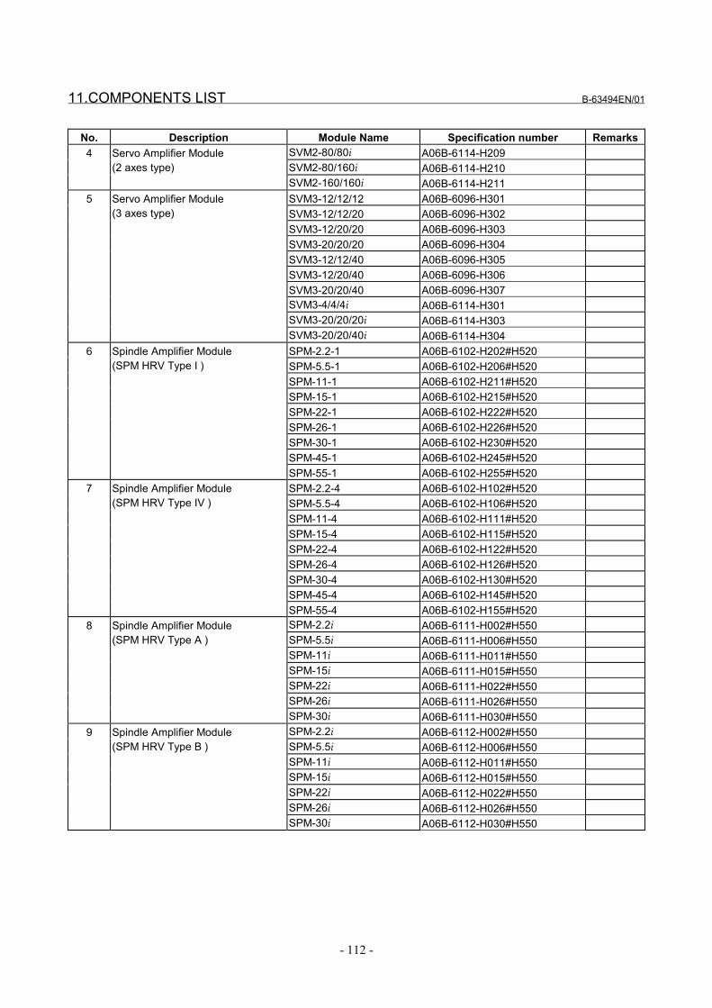
11.COMPONENTS LIST B-63494EN/01
- 112 -
No. Description Module Name Specification number RemarksSVM2-80/80i A06B-6114-H209SVM2-80/160i A06B-6114-H210
4 Servo Amplifier Module(2 axes type)
SVM2-160/160i A06B-6114-H211SVM3-12/12/12 A06B-6096-H301SVM3-12/12/20 A06B-6096-H302SVM3-12/20/20 A06B-6096-H303SVM3-20/20/20 A06B-6096-H304SVM3-12/12/40 A06B-6096-H305SVM3-12/20/40 A06B-6096-H306SVM3-20/20/40 A06B-6096-H307SVM3-4/4/4i A06B-6114-H301SVM3-20/20/20i A06B-6114-H303
5 Servo Amplifier Module(3 axes type)
SVM3-20/20/40i A06B-6114-H304SPM-2.2-1 A06B-6102-H202#H520SPM-5.5-1 A06B-6102-H206#H520SPM-11-1 A06B-6102-H211#H520SPM-15-1 A06B-6102-H215#H520SPM-22-1 A06B-6102-H222#H520SPM-26-1 A06B-6102-H226#H520SPM-30-1 A06B-6102-H230#H520SPM-45-1 A06B-6102-H245#H520
6 Spindle Amplifier Module(SPM HRV Type I )
SPM-55-1 A06B-6102-H255#H520SPM-2.2-4 A06B-6102-H102#H520SPM-5.5-4 A06B-6102-H106#H520SPM-11-4 A06B-6102-H111#H520SPM-15-4 A06B-6102-H115#H520SPM-22-4 A06B-6102-H122#H520SPM-26-4 A06B-6102-H126#H520SPM-30-4 A06B-6102-H130#H520SPM-45-4 A06B-6102-H145#H520
7 Spindle Amplifier Module(SPM HRV Type IV )
SPM-55-4 A06B-6102-H155#H520SPM-2.2i A06B-6111-H002#H550SPM-5.5i A06B-6111-H006#H550SPM-11i A06B-6111-H011#H550SPM-15i A06B-6111-H015#H550SPM-22i A06B-6111-H022#H550SPM-26i A06B-6111-H026#H550
8 Spindle Amplifier Module(SPM HRV Type A )
SPM-30i A06B-6111-H030#H550SPM-2.2i A06B-6112-H002#H550SPM-5.5i A06B-6112-H006#H550SPM-11i A06B-6112-H011#H550SPM-15i A06B-6112-H015#H550SPM-22i A06B-6112-H022#H550SPM-26i A06B-6112-H026#H550
9 Spindle Amplifier Module(SPM HRV Type B )
SPM-30i A06B-6112-H030#H550
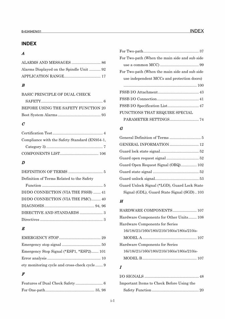
B-63494EN/01 INDEX
i-1
INDEX
AAAA
ALARMS AND MESSAGES ............................ 86
Alarms Displayed on the Spindle Unit ........... 92
APPLICATION RANGE................................... 17
BBBB
BASIC PRINCIPLE OF DUAL CHECK
SAFETY........................................................... 6
BEFORE USING THE SAFETY FUNCTION 20
Boot System Alarms ......................................... 93
CCCC
Certification Test ................................................ 4
Compliance with the Safety Standard (EN954-1,
Category 3) ...................................................... 7
COMPONENTS LIST..................................... 106
DDDD
DEFINITION OF TERMS ................................. 5
Definition of Terms Related to the Safety
Function .......................................................... 5
DI/DO CONNECTION (VIA THE FSSB) ....... 41
DI/DO CONNECTION (VIA THE PMC)......... 40
DIAGNOSIS................................................ 94, 96
DIRECTIVE AND STANDARDS ...................... 3
Directives ............................................................ 3
EEEE
EMERGENCY STOP........................................ 29
Emergency stop signal ..................................... 50
Emergency Stop Signal (*ESP1, *ESP2)....... 101
Error analysis ................................................... 10
ety monitoring cycle and cross-check cycle ....... 9
FFFF
Features of Dual Check Safety .......................... 6
For One-path............................................... 35, 98
For Two-path..................................................... 37
For Two-path (When the main side and sub side
use a common MCC) ..................................... 99
For Two-path (When the main side and sub side
use independent MCCs and protection doors)
...................................................................... 100
FSSB I/O Attachment....................................... 43
FSSB I/O Connection........................................ 41
FSSB I/O Specification List.............................. 47
FUNCTIONS THAT REQUIRE SPECIAL
PARAMETER SETTINGS............................ 74
GGGG
General Definition of Terms .............................. 5
GENERAL INFORMATION............................ 12
Guard lock state signal..................................... 52
Guard open request signal ............................... 52
Guard Open Request Signal (ORQ)............... 102
Guard state signal ............................................ 52
Guard unlock signal.......................................... 53
Guard Unlock Signal (*LGD), Guard Lock State
Signal (GDL), Guard State Signal (SGD).. 103
HHHH
HARDWARE COMPONENTS....................... 107
Hardware Components for Other Units........ 108
Hardware Components for Series
16i/18i/21i/160i/180i/210i/160is/180is/210is-
MODEL A .................................................... 107
Hardware Components for Series
16i/18i/21i/160i/180i/210i/160is/180is/210is-
MODEL B .................................................... 107
IIII
I/O SIGNALS .................................................... 48
Important Items to Check Before Using the
Safety Function ............................................. 20
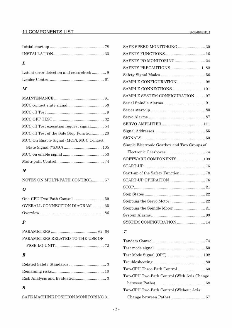
11.COMPONENTS LIST B-63494EN/01
- 2 -
Initial start-up .................................................. 78
INSTALLATION............................................... 33
LLLL
Latent error detection and cross-check ............. 8
Loader Control .................................................. 61
MMMM
MAINTENANCE .............................................. 81
MCC contact state signal ................................. 53
MCC off Test ....................................................... 9
MCC OFF TEST ............................................... 32
MCC off Test execution request signal............ 54
MCC off Test of the Safe Stop Function.......... 20
MCC On Enable Signal (MCF), MCC Contact
State Signal (*SMC) ................................... 105
MCC-on enable signal ...................................... 53
Multi-path Control............................................ 74
NNNN
NOTES ON MULTI-PATH CONTROL........... 57
OOOO
One-CPU Two-Path Control ............................ 59
OVERALL CONNECTION DIAGRAM........... 35
Overview ........................................................... 86
PPPP
PARAMETERS ........................................... 62, 64
PARAMETERS RELATED TO THE USE OF
FSSB I/O UNIT............................................. 72
RRRR
Related Safety Standards .................................. 3
Remaining risks................................................ 10
Risk Analysis and Evaluation............................ 3
SSSS
SAFE MACHINE POSITION MONITORING 31
SAFE SPEED MONITORING ......................... 30
SAFETY FUNCTIONS..................................... 16
SAFETY I/O MONITORING............................ 24
SAFETY PRECAUTIONS............................ 1, 82
Safety Signal Modes ......................................... 56
SAMPLE CONFIGURATION.......................... 98
SAMPLE CONNECTIONS ............................ 101
SAMPLE SYSTEM CONFIGURATION ......... 97
Serial Spindle Alarms....................................... 91
Series start-up................................................... 80
Servo Alarms..................................................... 87
SERVO AMPLIFIER ...................................... 111
Signal Addresses............................................... 55
SIGNALS........................................................... 50
Simple Electronic Gearbox and Two Groups of
Electronic Gearboxes .................................... 74
SOFTWARE COMPONENTS ........................ 109
START-UP......................................................... 75
Start-up of the Safety Function ....................... 78
START-UP OPERATION................................. 76
STOP.................................................................. 21
Stop States ........................................................ 22
Stopping the Servo Motor................................. 22
Stopping the Spindle Motor ............................. 21
System Alarms.................................................. 93
SYSTEM CONFIGURATION .......................... 14
TTTT
Tandem Control ................................................ 74
Test mode signal ............................................... 50
Test Mode Signal (OPT) ................................. 102
Troubleshooting ................................................ 80
Two-CPU Three-Path Control.......................... 60
Two-CPU Two-Path Control (With Axis Change
between Paths).............................................. 58
Two-CPU Two-Path Control (Without Axis
Change between Paths) ................................ 57

Rev
isio
n R
ecor
d
Dua
l Che
ck S
afet
y O
PER
ATO
R’S
MAN
UAL
(B-6
3494
EN)
01Fe
b., 2
002
Editi
onD
ate
Con
tent
sEd
ition
Dat
eC
onte
nts


TECHNICAL REPORT (MANUAL) NO.TMN 00 / 117E
Date: . .2000.General Manager ofHardware Laboratory
Dual Check Safety USER’S MANUAL
1. Communicate this report to:
Your information only GE Fanuc-N, GE Fanuc-E
FANUC Robotics CINCINNATI MILACRON Machine tool builder Sales agency End user
2. Summary for Sales Documents(Sales guide, Functional comparison list, etc.)
3. Notice
4. Attached Document
DrawingNo.
B-63494EN/01-05
Original section of issueGeneralManager
Vice GeneralManager
DepartmentManager
SectionManager
Person inCharge
FANUC
IDE

B-63494EN-01
Version 05: 25th of July, 2000
USER’S MANUAL

Table of Contents B-63494EN/01
c-2
Table of Contents
1 OVERVIEW.............................................................................................................................................. 1
1.1 DIRECTIVE AND STANDARDS ..................................................................................................... 3
1.1.1 Directives .................................................................................................................................... 3
1.1.2 Related Safety Standards.......................................................................................................... 3
1.1.3 Risk Analysis and Evaluation................................................................................................... 3
1.1.4 Certification Test.................................................................................................................... 5
1.2 DEFINITION OF TERMS ......................................................................................................................... 6
1.2.1 General Definition of Terms ................................................................................................... 6
1.2.2 Definition of Terms Related to the Safety Function ......................................................... 6
1.3 BASIC PRINCIPLE OF DUAL CHECK SAFETY .......................................................................................... 8
1.3.1 Features of Dual Check Safety................................................................................................ 8
1.3.2 Compliance with the Safety Standard (EN954-1, Category 3)................................................ 8
1.4 GENERAL INFORMATION........................................................................................................... 16
2 SYSTEM CONFIGURATION ............................................................................................................. 18
3 SAFETY FUNCTIONS......................................................................................................................... 20
3.1 APPLICATION RANGE ................................................................................................................. 21
3.2 BEFORE USING THE SAFETY FUNCTION............................................................................... 25
3.2.1 Important Items to Check Before Using the Safety Function ................................................ 25
3.2.2 MCC off Test of the Safe Stop Function.................................................................................. 25
3.3 STOP ................................................................................................................................................ 26
3.3.1 Stopping the Spindle Motor .................................................................................................... 26
3.3.2 Stopping the Servo Motor ........................................................................................................ 27
3.3.3 Stop States................................................................................................................................ 27
3.4 SAFETY I/O MONITORING .......................................................................................................... 30
3.5 EMERGENCY STOP ...................................................................................................................... 37
3.6 SAFE SPEED MONITORING........................................................................................................ 39
3.7 SAFE MACHINE POSITION MONITORING .............................................................................. 41
3.8 MCC OFF TEST .............................................................................................................................. 42
4 INSTALLATION ................................................................................................................................... 43
4.1 OVERALL CONNECTION DIAGRAM ......................................................................................... 43
4.2 DI/DO CONNECTION (VIA THE PMC) ....................................................................................... 47
4.3 DI/DO CONNECTION (VIA THE FSSB) ...................................................................................... 48
4.3.1 FSSB I/O Connection.............................................................................................................. 48

B-63494EN/01 Table of Contents
c-3
4.3.2 FSSB I/O Attachment ............................................................................................................. 49
4.3.3 FSSB I/O Specification List ................................................................................................... 55
5 I/O SIGNALS ......................................................................................................................................... 56
5.1 OVERVIEW......................................................................................................................................... 57
5.2 SIGNALS ............................................................................................................................................ 58
5.2.1 Signal Addresses...................................................................................................................... 61
5.2.2 Safety Signal Modes ................................................................................................................ 62
6 PARAMETERS...................................................................................................................................... 64
6.1 OVERVIEW......................................................................................................................................... 65
6.2 PARAMETERS..................................................................................................................................... 66
7 MAINTENANCE ................................................................................................................................... 72
7.1 SAFETY PRECAUTIONS............................................................................................................... 73
7.2 ALARMS............................................................................................................................................. 77
7.2.1 Servo Alarms............................................................................................................................ 77
7.2.2 Serial Spindle Alarms ............................................................................................................. 81
7.2.3 Alarms Displayed on the Spindle Unit................................................................................... 82
7.2.4 System Alarms ......................................................................................................................... 84
7.2.5 Boot System Alarms................................................................................................................. 84
8 START-UP ............................................................................................................................................. 85
8.1 START-UP OPERATION ......................................................................................................................... 86
8.1.1 Acceptance test and report for safety functions............................................................. 86
8.1.2 Start-up of the Safety Function .......................................................................................... 88
8.1.3 Troubleshooting ....................................................................................................................... 91
9 SAMPLE SYSTEM CONFIGURATION............................................................................................ 92
9.1 SAMPLE CONFIGURATION......................................................................................................... 93
9.2 SAMPLE CONNECTIONS............................................................................................................. 94
9.2.1 Emergency Stop Signal (*ESP1, *ESP2)................................................................................ 94
9.2.2 Guard Open Request Signal (ORQ) ........................................................................................... 95
9.2.3 Test Mode Signal (OPT) ............................................................................................................. 95
9.2.4 Guard Unlock Enable Signal (*LGD), Guard Lock State
Signal (GDL), Guard State Signal (SGD) ............................................................................................. 97
9.2.5 MCC On Enable Signal (MCF), MCC Contact State
Signal (*SMC) ......................................................................................................................................... 99

Table of Contents B-63494EN/01
c-4
10 COMPONENTS LIST.....................................................................................................................100

B-63494EN/01 1.OVERVIEW
-1-
OVERVIEWSetup for machining, which includes attaching and detachinga workpiece to be machined, and moving it to the machiningstart point while viewing it, is performed with theprotection door opened. The dual check safety functionprovides a means for ensuring a high level of safety withthe protection door opened.
The simplest method of ensuring safety when the protectiondoor is open is to shut off power to the motor drivecircuit by configuring a safety circuit with a safety relaymodule. In this case, however, no movements can be made ona move axis (rotation axis). Moreover, since the power isshut off, some time is required before machining can berestarted. This drawback can be corrected by adding amotor speed detector to ensure safety. However, theaddition of an external detector may pose a responseproblem, and the use of many safety relay modules resultsin a large and complicated power magnetics cabinet circuit.
With the dual check safety function, two independent CPUsbuilt into the CNC monitor the speed and position of motorsin dual mode. An error in speed and position is detectedat high speed, and power to the motor is shut off via twoindependent paths. Processing and data related to safetyis cross-checked by two CPUs. To prevent failures frombeing built up, a safety-related hardware and software testmust be conducted at certain intervals time.
The dual check safety system need not have an externaldetector added. Instead, only a detector built into aservo motor or spindle motor is used. This configurationcan be implemented only when those motors, detectors builtinto motors, and amplifiers that are specified by FANUC areused. When an abnormality related to safety occurs, thedual check safety function stops operation safely.
The dual check safety function ensures safety with thepower turned on, so that an operator can open theprotection door to work without turning off the power. Amajor feature of the dual check safety function is a veryshort time required from the detection of an abnormalityuntil the power is shut off. A cost advantage of the dualcheck safety function is that external detectors and safetyrelays can be eliminated or simplified.

1.OVERVIEW B-63494EN/01
-2-
The dual check safety function consists of the followingthree functions:
1. Safety I/O monitoring function2. Safety limitation speed monitoring function3. Safety machine position monitoring function
The safety function operates regardless of the NC mode.Usually, this function should be used in the setup mode.If a position or speed mismatch is detected by a cross-check using two CPUs, power is shut off (MCC off) to themotor drive circuit.
The European standard certification organization hascertified that this safety function satisfies the EuropeanSafety Standard EN954-1 Category 3.
IMPORTANT
The dual check safety function cannot monitor the stopstate. For details, see the example of systemconfiguration.
!
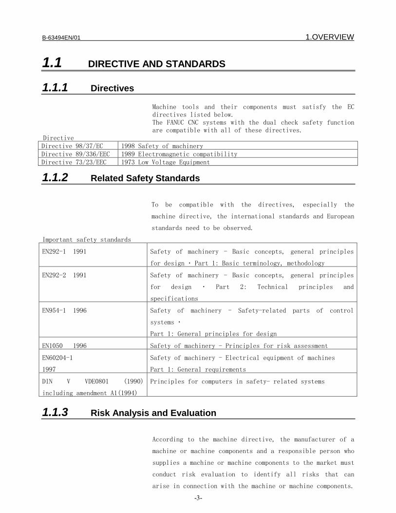
B-63494EN/01 1.OVERVIEW
-3-
1.1 DIRECTIVE AND STANDARDS
1.1.1 Directives
Machine tools and their components must satisfy the ECdirectives listed below.The FANUC CNC systems with the dual check safety functionare compatible with all of these directives.
DirectiveDirective 98/37/EC 1998 Safety of machineryDirective 89/336/EEC 1989 Electromagnetic compatibilityDirective 73/23/EEC 1973 Low Voltage Equipment
1.1.2 Related Safety Standards
To be compatible with the directives, especially the
machine directive, the international standards and European
standards need to be observed.
Important safety standards
EN292-1 1991 Safety of machinery - Basic concepts, general principles
for design – Part 1: Basic terminology, methodology
EN292-2 1991 Safety of machinery - Basic concepts, general principles
for design – Part 2: Technical principles and
specifications
EN954-1 1996 Safety of machinery - Safety-related parts of control
systems –
Part 1: General principles for design
EN1050 1996 Safety of machinery - Principles for risk assessment
EN60204-1
1997
Safety of machinery - Electrical equipment of machines
Part 1: General requirements
DIN V VDE0801 (1990)
including amendment A1(1994)
Principles for computers in safety- related systems
1.1.3 Risk Analysis and Evaluation
According to the machine directive, the manufacturer of a
machine or machine components and a responsible person who
supplies a machine or machine components to the market must
conduct risk evaluation to identify all risks that can
arise in connection with the machine or machine components.

1.OVERVIEW B-63494EN/01
-4-
Based on such risk analysis and evaluation, a machine and
machine components must be designed and manufactured. Risk
evaluation must reveal all remaining risks and must be
documented.
B-63494EN/01 1.OVERVIEW
-5-
1.1.4 Certification Test Certification Test Certification Test Certification Test
Certification of the dual check safety function
The German certification organization TUV PS has certified
that the dual check safety function satisfies EN954-1
Category 3.

1.OVERVIEW B-63494EN/01
-6-
1.2 DEFINITION OF TERMSDEFINITION OF TERMSDEFINITION OF TERMSDEFINITION OF TERMS
1.2.1 General General General General DefinitionDefinitionDefinitionDefinition of Terms of Terms of Terms of Terms
Reliability and safety
Reliability and safety are defined by EN292-1 as follows:
Term Definition
Reli-
ability
Capability of a machine, machine component, or
equipment to perform its required function
under a specified condition for a specified
period
Safety Capability of a machine to perform its function
without injuring the health under a condition
of use for an intended purpose specified in the
operator's manual and allow its transportation,
installation, adjustment, maintenance,
disassembly, and disposal
1.2.2 DefinitionDefinitionDefinitionDefinition of Terms Related to the of Terms Related to the of Terms Related to the of Terms Related to the SafetySafetySafetySafety FunctionFunctionFunctionFunction
Safety-related I/O signal
Safety-related I/O signals are input/output signals
monitored by two systems. These signals are valid for each
feed axis and spindle with a built-in safety function, and
are used with each monitoring system.
Example: Protection door state signal
Safety stop
When a safety stop occurs, power to the drive section is
shut off. The drive section can generate neither a torque
nor dangerous operation. The following are measures for
incorporating the safety stop feature:
Contactor between the line and drive system (line

B-63494EN/01 1.OVERVIEW
-7-
contactor)
Contactor between the power section and drive motor (motor
contactor)
If an external force is applied (such as a force applied
onto a vertical axis), an additional measure (such as a
mechanical brake) must be securely implemented to protect
against such a force.
Safety limitation speed
Feature for preventing the drive section from exceeding a
specified speed. A measure must be implemented to prevent
a set limitation speed from being changed by an
unauthorized person.
Safety machine position
When the drive system has reached a specified positional
limit, a transition is made to the safety stop state. When
a positional limit is set, a maximum move distance traveled
until a stop occurs must be considered. A measure must be
implemented to prevent a set positional limit from being
changed by an unauthorized person.
1.OVERVIEW B-63494EN/01
-8-
1.3 BASIC PRINCIPLE OF DUAL CHECK BASIC PRINCIPLE OF DUAL CHECK BASIC PRINCIPLE OF DUAL CHECK BASIC PRINCIPLE OF DUAL CHECK SAFETYSAFETYSAFETYSAFETY
1.3.1 Features of Dual Check Features of Dual Check Features of Dual Check Features of Dual Check SafetySafetySafetySafety
− Two-channel configuration with two or more independent
CPUs
− Cross-check function for detecting latent errors
Detection
A servo motor detector signal is sent via the servo
amplifier and is applied to the CNC through the FSB
interface. Then, it is fed to two CPUs: a CNC CPU and a
monitor CPU.
A spindle motor detector signal is sent via the spindle
amplifier and is applied to the CNC connected through the
serial interface. Then, it is fed to two CPUs: a CNC CPU
and a CPU built into the spindle amplifier.
Evaluation
The safety function is monitored independently by a CNC CPU
and monitor CPU or by a CNC CPU and spindle CPU. Each CPU
cross-checks data and results at certain intervals.
Response
If the monitoring function detects an error, the CNC CPU
and monitor CPU switch off the MCC via independent paths to
shut off the power to the feed axis and spindle.
1.3.2 Compliance with the Safety Standard (EN954-1, Category 3)
The dual check safety function satisfies the requirementsof Category 3 of the safety standard EN954-1.
Category 3 requires the following:
− The safety function of a safety-related portion must not
degrade when a single failure occurs.− Single errors must be detected at all times when
natural execution is possible.
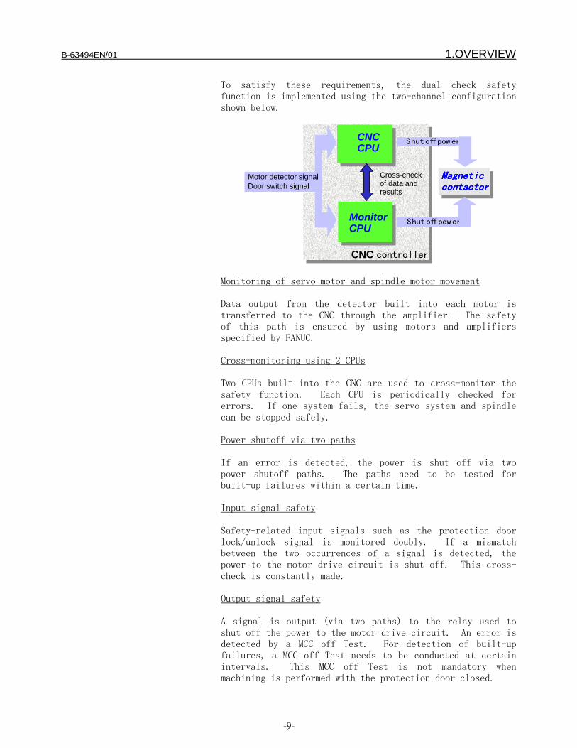
B-63494EN/01 1.OVERVIEW
-9-
To satisfy these requirements, the dual check safetyfunction is implemented using the two-channel configurationshown below.
CNCCPU
CNCCPU
MonitorCPU
MonitorCPU
Motor detector signalDoor switch signal
MagneticMagneticMagneticMagneticcontactorcontactorcontactorcontactor
Shut off pow er
Shut off pow er
CNC controller
Cross-checkof data andresults
Monitoring of servo motor and spindle motor movement
Data output from the detector built into each motor istransferred to the CNC through the amplifier. The safetyof this path is ensured by using motors and amplifiersspecified by FANUC.
Cross-monitoring using 2 CPUs
Two CPUs built into the CNC are used to cross-monitor thesafety function. Each CPU is periodically checked forerrors. If one system fails, the servo system and spindlecan be stopped safely.
Power shutoff via two paths
If an error is detected, the power is shut off via twopower shutoff paths. The paths need to be tested forbuilt-up failures within a certain time.
Input signal safety
Safety-related input signals such as the protection doorlock/unlock signal is monitored doubly. If a mismatchbetween the two occurrences of a signal is detected, thepower to the motor drive circuit is shut off. This cross-check is constantly made.
Output signal safety
A signal is output (via two paths) to the relay used toshut off the power to the motor drive circuit. An error isdetected by a MCC off Test. For detection of built-upfailures, a MCC off Test needs to be conducted at certainintervals. This MCC off Test is not mandatory whenmachining is performed with the protection door closed.

1.OVERVIEW B-63494EN/01
-10-
1.3.2.1 Latent Latent Latent Latent errorerrorerrorerror detectiondetectiondetectiondetection and and and and cross-checkcross-checkcross-checkcross-check
Detection of latent errors
This detection function can detect latent software and
hardware errors in a system that has a two-channel
configuration. So, the safety-related portions of the two
channels need to be tested at least once within an
allowable period of time for latent errors.
An error in one monitoring channel causes a mismatch of
results, so that a cross-check detects the error.
Caution
Forced detection of a latent error on the MCC shutoff path
must be performed by the user through a MCC off Test (after
power-on and at intervals of a specified time (within 24
hours)).
When the system is operating in the automatic mode (when
the protection door is closed), this detection processing
is not requested as mandatory.
Cross-check
A latent safety-related error associated with two-channel
monitoring can be detected as a result of cross-checking.
For numeric data, an allowable difference between the two
channels is set in a parameter. (For example, an allowable
cross-checked difference is set for the actual position.)
Note
An error detected as the result of forced latent error
detection or cross-checking leads to a safety stop state.
(See Chapter ?.).
1.3.2.2 SafetySafetySafetySafety monitoringmonitoringmonitoringmonitoring cyclecyclecyclecycle and and and and cross-checkcross-checkcross-checkcross-check cyclecyclecyclecycle
The safety function is subject to periodical monitoring in
a monitoring cycle.
Monitoring cycle: 16 ms

B-63494EN/01 1.OVERVIEW
-11-
The cross-check cycle represents a cycle at which all data
subject to cross-checking is compared.
Cross-check cycle: 16 ms
1.3.2.3 MCC off Test MCC off Test MCC off Test MCC off Test
The MCC is shut off using two CPUs: a CNC CPU and monitor
CPU. To detect a latent error in the MCC shutoff paths
forcibly, a MCC off Test is conducted. This test is
essential to dual check safety. A MCC off Test must be
conducted at specified times (after power-on and at
intervals of 24 hours) to check that the MCC shutoff paths
operate normally. A MCC off Test is conducted once on the
CNC side and once on the monitor side. When a MCC off Test
becomes necessary, the CNC outputs a MCC off Test execution
request signal to the PMC.
Note
The machine tool builder is to warn and prompt the operator
to conduct a MCC off Test when a MCC off Test execution
request signal is output. A MCC off Test is executed by
turning on the test mode signal.
MCC off Test execution condition
− All axes and the spindle must be stopped beforehand.
− All vertical axes must be secured firmly beforehand.
Select-test termination
When a MCC off Test is completed, the MCC off Test
execution request signal is turned off. After the MCC off
Test execution request signal is turned off, turn off the
test mode signal.
1.3.2.4 ErrorErrorErrorError analysisanalysisanalysisanalysis
Error analysis
The table below indicates the results of system error
analysis controlled by the dual check safety function.

1.OVERVIEW B-63494EN/01
-12-
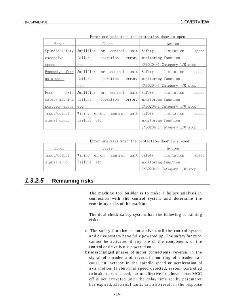
B-63494EN/01 1.OVERVIEW
-13-
Error analysis when the protection door is open
Error Cause Action
Spindle safety
excessive
speed
Amplifier or control unit
failure, operation error,
etc.
Safety limitation speed
monitoring function
EN60204-1 Category 1/0 stop
Excessive feed
axis speed
Amplifier or control unit
failure, operation error,
etc.
Safety limitation speed
monitoring function
EN60204-1 Category 1/0 stop
Feed axis
safety machine
position error
Amplifier or control unit
failure, operation error,
etc.
Safety limitation speed
monitoring function
EN60204-1 Category 1/0 stop
Input/output
signal error
Wiring error, control unit
failure, etc.
Safety limitation speed
monitoring function
EN60204-1 Category 1/0 stop
Error analysis when the protection door is closed
Error Cause Action
Input/output
signal error
Wiring error, control unit
failure, etc.
Safety limitation speed
monitoring function
EN60204-1 Category 1/0 stop
1.3.2.5 Remaining risks
The machine tool builder is to make a failure analysis inconnection with the control system and determine theremaining risks of the machine.
The dual check safety system has the following remainingrisks:
a) The safety function is not active until the control systemand drive system have fully powered up. The safety functioncannot be activated if any one of the components of thecontrol or drive is not powered on.
b) Interchanged phases of motor connections, reversal in thesignal of encoder and reversal mounting of encoder cancause an increase in the spindle speed or acceleration ofaxis motion. If abnormal speed detected, system controlledto brake to zero speed, but no effective for above error. MCCoff is not activated until the delay time set by parameterhas expired. Electrical faults can also result in the response

1.OVERVIEW B-63494EN/01
-14-
described above(component failure too).c) Faults in the absolute encoder can cause incorrect
operation of the safety machine position monitoringfunction.
d) With a 1-encoder system, encoder faults are detected in asingle channel, but by various HW and SE monitoringfunctions. The parameter related to encoder must be setcarefully. Depending on the error type, a category 0 orcategory 1 stop function according to EN60204-1 isactivated.
e) The simultaneous failure of two power transistors in theinverter may cause the axis to briefly(motion depend onnumber of pole pairs of motor)Example:A 6-pole synchronous motor can cause the axis to move by amaximum of 30 degrees. With a lead-screw that is directlydriven by, e.g.20mm per revolution, this corresponds to amaximum linear motion of approximately 1.6mm.
f) When a limit value is violated, the speed may exceed the setvalue briefly or the axis/spindle overshoot the setpointposition to a greater or lesser degree during the periodbetween error detection and system reaction depending onthe dynamic response of the drive and the parametersettings(see Section Safety-Functions)
g) The category 0 stop function according to EN60204-1(defined as STOP A in Safety Integrated) means that thespindles/axes are not braked to zero speed, but coast to astop (this may take a very long time depending on the levelof kinetic energy involved). This must be noted, for example,when the protective door locking mechanism is opened.
h) Drive power modules and motors must always be replacedby the same equipment type or else the parameters will nolonger match the actual configuration and cause Dual checkSafety to respond incorrectly.
i) Dual check Safety is not capable of detecting errors inparameterization and programming made by the machinemanufacturer. The required level of safety can only beassured by thorough and careful acceptance.
j) There is a parameter that MCC off test is not to be made inthe self test mode at power-on as in the case of machineadjustment. This parameter is protected, only changed byauthorized person. IF MCC off test is not conducted, MCCmay not be off at stop response is measured.
k) Safety machine position monitoring function does not applyto rotation axis.
l) During machine adjustment, an exact motion may beexecuted incorrectly untie the safety functions setup

B-63494EN/01 1.OVERVIEW
-15-
correctly and confirm test is completely.
1.OVERVIEW B-63494EN/01
-16-
1.4 GENERAL INFORMATIONThe following requirements must be fulfilled for the Dual-CheckSystem:− All conditions of the certification report has to be
respected.− The procedures for the changes in the System (either HW or SW)
should be referred to maintenance manual (B-63005). Whensafety related components are exchanged, confirmation testregarding safety functions can be performed accoding to Chapter8.
− Programming in ladder logic should be referred to programmingmanual (B-61863).
TrainingFANUC Training Center provides versatile training course for theperson who is concerned with hardware installation, maintenance andoperation. FANUC recommend studying and learning in the trainingcenter how efficiently operate FANUC products.There are 3 CNC training course.
[ CNC ELEMENTARY COURSE ]Provides basics of CNC functions, operation and programming. Thecourse is recommended before taking more specialized trainingcourses to gain best effects.
MAIN ITEMS OF TRAINING− CNC functions− Configuration of CNC− Configuration and function of servo system− Basic programming of CNC− Part programming of milling machine− Part programming of turning machine− Introduction of Custom Macro function
[ CNC MAINTENANCE COURSE ]To master maintenance technique that permits you to maintain andinspect CNC, also how to restore it promptly if a trouble shouldoccur.
MAIN ITEMS OF TRAINING− Function and configuration of Power Unit− Function and configuration of CNC system− include AC servo and AC spindle− Self-diagnosis function− Interface between CNC and the machine tools− Data saving and restoring operation− Trouble shooting

B-63494EN/01 1.OVERVIEW
-17-
[ CNC SE INTERFACE COURSE ]Training course offered to the engineers who design CNC machinetools or CNC application system for the first time. This course is alsosuitable for customers who provide to retrofitting, to develop anoriginal CNC machine tools or new application of CNC.
MAIN ITEMS OF TRAINING− Configuration of CNC system− Interface between CNC and machine tools− Ladder programming of machine control sequence− Setting of parameter related to machine− Setting of parameter related to servo and spindle
More information and course registrationYamanakako-mura, Yamanashi Prefecture : 401-0501, JAPANPhone : 81-555-84-6030Fax : 81-555-84-5540Internet:www.fanuc.co.jp/eschool

2.SYSTEM CONFIGURATION B-63494EN/01
-18-
SYSTEM CONFIGURATIONFANUC Series 16i/18i/20i/21i/160is/180is/210is/160i/180i/210i(LCD-mounted type)FANUC Series 16i/18i/21i/160is/180is/210is/160i/180i/210i (stand-alone type)
Number of controlled axes- Series 20i/21i/210is/210i : 4 maximum- Series 18i/180is/180i : 6 maximum- Series 16i/160iis/160i : 6 maximum
Number of spindle controlled axes- Series 21i/210is/210i : 2 maximum- Series 18i/180is/180i : 3 maximum- Series 16i/160is/160i : 4 maximum
Amplifier- α series servo amplifier- α series spindle amplifier- α series power supply module
Motor- α series servo motor- α series spindle motor
I/O- I/O unit (I/O Link)- I/O module (FSSB)
Software- Dual check software
DETECTOR SYSTEM
The detectors below can be used.
Feed axis detector- Servo motor built into α1000- Separate detector (A/B phase pulse)
Spindle detector- M sensor- MZ sensor- BZ sensor

B-63494EN/01 2.SYSTEM CONFIGURATION
-19-
CAUTION
The dual check safety system can not be used belowfunctions
- I/O Linkβ- SUB CPU- Loader control function- two path control function- EGB function- Spindle switching function- Linear Motor- System of more than twe protectctiv doors- Background graphic function- HRV3 control- Open CNC (LCD-mounted type)- Speed command of the axis control by PMC
3.SAFETY FUNCTIONS B-63494EN/01
-20-
SAFETY FUNCTIONS
B-63494EN/01 3.SAFETY FUNCTIONS
-21-
3.1 APPLICATION RANGEThe dual check safety system assumes the following
configuration:
A) One protective door is provided.
B) If the protective door is closed, safety is
assured.
When the operator makes a request to open the
protective door, the safety functions are enabled, and
the protective door can be unlocked. While the
protective door is open, the active safety functions
assure safety. When the request to open the protective
door is canceled, the protective door is locked, and
the safety functions are disabled.
The dual check safety system provides these safety
functions while the protective door is open, as
described above. Some of the safety functions continue
working while the protective door is closed.
WARNING
Each machine tool builder should take measures to
assure safety while the protective door is closed and
to ensure safety related to a rotation axis and travel
axis. At the same time, safety measures for the FANUC
servo motor or spindle motor need to be taken, while
the door is open.
The dual check safety system has the following safety
functions:
- Safety I/O monitoring
This function in redundant mode monitors I/O related to
safety (emergency stop, protective door lock/open/close
state, power-down) in redundant mode. The emergency
stop, protective door lock/open/close state, and power-
down are checked in redundant mode. If the two
corresponding inputs do not match, the system judges
that an abnormal event has occurred. The power-down
!

3.SAFETY FUNCTIONS B-63494EN/01
-22-
(MCC off) signal is output in redundant mode (from two
paths). Whether the two-path output is normal is
judged in a MCC off Test.
- Safe speed monitoring
This function checks that the rotation speeds of the
servo motor and spindle motor are within a
predetermined speed range, using two CPUs in redundant
mode. If a speed exceeding the range is detected, the
system judges that an abnormal event has occurred.
- Safe machine position monitoring
This function checks that the position on a servo axis
is within a specified range, using two CPUs in
redundant mode. If a position exceeding the range is
detected, the system judges that an abnormal event has
occurred.
If an abnormal event (safety error) is found, the dual
check safety system shuts off the power to the motor
driving circuit, using the two independent CPUs. The
state in which the servo or spindle motor stops because
of power-down is referred to as the safe stop state.
If a safety error results in the safe stop state, the
operator must turn off the CNC, remove the cause of the
error, then turn on the CNC again. The user must
conduct a MCC off Test every 24 hours in order to
detect a potential cause of error.
CAUTION
This safety function is enabled while the protective
door is open after a request to open the protective
door is made. If the request to open the protective
door is canceled and if the protective door is closed,
this safety function is disabled.
The dual input check of the safety I/O monitoring
function and the emergency stop function are always
active, regardless of whether the protective door is
opened or closed.

B-63494EN/01 3.SAFETY FUNCTIONS
-23-
Protectivedoor
Emergency
stop
Servo motor
Spindlemotor
Power-down
(MCC)
CNC
CPU
Monitor
CPU
Spindle CPU
PSM
SVM
SPM
Safe speed monitoring
Safe speed monitoringSafe machine positionmonitoring
Door lock/open/closemonitoring
Cross-check
Cross-
CNC
Dual monitoring of MCCDual power-downDetection of potential cause of error byself test
I/O, safe speed ofthe servo motor, andmachine positionare checked by theCNC CPU andmonitor CPU inredundant mode.
The safe speed ofthe spindle motor ischecked by the CNCCPU and spindleCPU in redundantmode.
Dual monitoring of protective door state
Protective door
lock signal
Power-down
Dual monitoring of MCC
Dual monitoring of emergencystop signal

3.SAFETY FUNCTIONS B-63494EN/01
-24-
Safety functionsSafety functionsSafety functionsSafety functions
- Double monitoring of input signals
Emergency stop input, protective door lock/open/close
state, relay state for turning off the MCC
- Dual signal output
Output signal for shutting off the power (turning the
MCC off)To detect the potential cause of an abnormal
state of this output, a MCC off Test must be made.
- Spindle motor
Safe speed monitoring
- Servo motor
Safe speed monitoring
Safe machine position monitoring

B-63494EN/01 3.SAFETY FUNCTIONS
-25-
3.2 BEFORE USING THE SAFETY FUNCTION3.2.1 Important Items to Check Before Using the Safety Function
− When using the safety function for the first time
upon assembly of the machine, replacing a part, or
changing a safety parameter (such as a safe speed
limit or safe range as described in Chapter n), the
user must check that all safety parameters are
correct and that all safety functions are working
normally. A return reference position must be made
on each axis. The user must also check the
absolute position of the machine. For details, see
Chapter 8, "START UP."
− If an absolute-position detector is used, and reference positionreturn has been performed once, reference position data is storedin the CNC memory. In this case, the user need not make areference position check.
− If an incremental pulse coder is being used, reference positiondata is lost each time the power to the CNC is turned off and thenback on. So, after the power is turned on, another referenceposition return operation must be performed.
− At the every power on the safety area must be tested.
− At each power on there is a message: “Please execute safetytest”Without this message dual check safety is either notinstalled or not yet activated (option bit).
3.2.2 MCC off Test of the Safe Stop Function
A MCC off Test of the safe stop function monitors the
contact state of the electromagnetic contactor (MCC),
compares the state with a command to the
electromagnetic contactor, and checks that the safe
stop function works normally. The test must be carried
out by the user of the machine. This test must be
carried out when the CNC is turned on or when 24 hours
have elapsed after the previous test is completed. If
the CNC is turned on or if 24 hours have elapsed after
the previous test is completed, a guard open request
(protective door open request) is not accepted until
the test is performed.
3.SAFETY FUNCTIONS B-63494EN/01
-26-
3.3 STOP
3.3.1 Stopping the Spindle Motor
Because the spindle motor is an induction type motor,
power-down during rotation causes the motor to continue
rotating for a certain amount of time. From a safety
standpoint, the motor may have to be stopped
immediately. If the CNC detects an error and judges
that the spindle can be controlled, it waits until the
rotation of the spindle stops, then shuts off the
power. This wait period can be specified as a safety
parameter. For this safety parameter, two different
values can be specified. One value is used when the
safety function is active (the door is open), and the
other value is used otherwise. The values must be
determined in consideration of the stop period
calculated from the spindle speed.
To implement the function, the CNC CPU and monitor CPU
individually incorporate a timer function. Normal
operation of the two CPUs are mutually checked to
ensure the safety of the timers.
To speed down and stop the spindle, the PMC must input
the *SPEMG signal. When this signal is input, the
spindle slows down and stops. (A Ladder program for
inputting this signal in case of alarm must be
created.) The *EMG input of the PSM has the same
effect. If the emergency stop signal is connected to
*EMG, the spindle slows down and stops in the emergency
stop state.
If this processing is not performed, power-down causes
the spindle motor to continue rotating at the speed
prior to power-down (and eventually stopping in the
end).
CAUTION
The CNC outputs a DO notifying of an alarm. If
necessary, the spindle should be stopped. Because the
DO output is not duplicated, this DO may not be output
when a single failure is detected. In that case, the
speed cannot be reduced, but the MCC is finally shut
off and brought into the safe stop state.
If a spindle amplifier alarm or any other state in

B-63494EN/01 3.SAFETY FUNCTIONS
-27-
which the spindle motor cannot be controlled is
encountered, immediate power-down is carried out.
3.3.2 Stopping the Servo Motor
Because the servo motor is a synchronous motor, power-
down results in a dynamic brake stop. The dynamic
brake stop is electric braking in which the excited
rotor is isolated from the power source and the
generated electric energy is used up in the winding.
Additional braking is provided by an internal resistor.
Unlike an induction motor, the servo motor does not
coast because of this function.
If the input of the emergency stop signal or an error
of a safety signal or speed monitoring is detected, the
CNC automatically specifies a command to zero the speed
and reduces the speed to zero (controlled stop). After
the motor slows down and stops, the power is turned
off, and the motor is brought into the dynamic brake
stop state. To slow down and stop the motor, some
parameters must be specified in the CNC. If those
parameters are not specified, the motor is immediately
brought into the dynamic brake stop state. In some
circumstances where a controlled stop cannot be made, a
dynamic brake stop is unconditionally made.
3.3.3 Stop States
The following stop states are possible:
Safe stop state
The power to the motor is shut off (MCC off state). If
the spindle motor can be controlled, the power is shut
off after the spindle motor is slowed down to a stop.
If the spindle motor cannot be controlled, the power is
immediately shut off.
If the servo motor can be controlled, the motor is
slowed down to a stop and then brought into the dynamic
brake stop state. If the motor cannot be controlled,
the motor is immediately brought into the dynamic brake
stop state.
If the power is shut off immediately, the spindle motor
continues at the same speed prior to the abnormal event
and eventually comes to a stop. If the spindle motor

3.SAFETY FUNCTIONS B-63494EN/01
-28-
can be slowed down to a stop, the operation is
performed as instructed by the PMC and then the power
is shut off.
IMPORTANT
The time period until the signal for shutting off the
power (turning off the MCC) is output depends on the
parameter. Different parameters are used in the safety
monitoring state and in other states.
Safety parameter
number
Name
1947 MCC off timer 1 If the protective
door is closed
1948 MCC off timer 2 If the protective
door is opened
Controlled stop state
The power to the motor is not shut off.
The servo motor and the spindle motor are controlled to
stop.
In the controlled stop state of either motor, the
safety function is active if the condition for enabling
the safety function is satisfied (the door is open).
If a further abnormal event occurs, the motor is
brought into the safe stop state.
WARNING
- The machine tool builder must design the machine so
that the machine is kept in the stop state if the power
to the servo motor driving circuit is shut off.
Example) Brake mechanism that would not drop the
vertical axis after the power is shut off
- If the power to the spindle motor driving circuit is
shut off, the spindle motor continues rotating at the
speed before the power-down and eventually comes to a
stop. A measure must be taken so that this coasting
does not affect safety.
!
!

B-63494EN/01 3.SAFETY FUNCTIONS
-29-
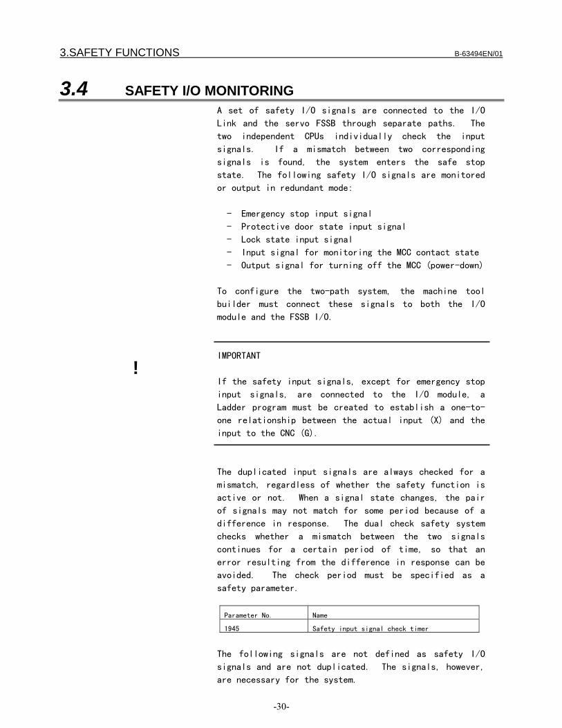
3.SAFETY FUNCTIONS B-63494EN/01
-30-
3.4 SAFETY I/O MONITORINGA set of safety I/O signals are connected to the I/O
Link and the servo FSSB through separate paths. The
two independent CPUs individually check the input
signals. If a mismatch between two corresponding
signals is found, the system enters the safe stop
state. The following safety I/O signals are monitored
or output in redundant mode:
- Emergency stop input signal
- Protective door state input signal
- Lock state input signal
- Input signal for monitoring the MCC contact state
- Output signal for turning off the MCC (power-down)
To configure the two-path system, the machine tool
builder must connect these signals to both the I/O
module and the FSSB I/O.
IMPORTANT
If the safety input signals, except for emergency stop
input signals, are connected to the I/O module, a
Ladder program must be created to establish a one-to-
one relationship between the actual input (X) and the
input to the CNC (G).
The duplicated input signals are always checked for a
mismatch, regardless of whether the safety function is
active or not. When a signal state changes, the pair
of signals may not match for some period because of a
difference in response. The dual check safety system
checks whether a mismatch between the two signals
continues for a certain period of time, so that an
error resulting from the difference in response can be
avoided. The check period must be specified as a
safety parameter.
Parameter No. Name
1945 Safety input signal check timer
The following signals are not defined as safety I/O
signals and are not duplicated. The signals, however,
are necessary for the system.
!
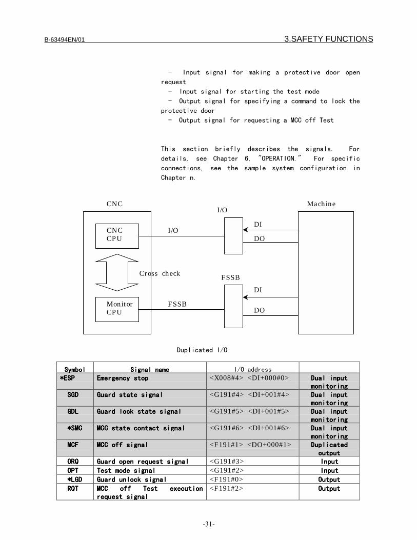
B-63494EN/01 3.SAFETY FUNCTIONS
-31-
- Input signal for making a protective door open
request
- Input signal for starting the test mode
- Output signal for specifying a command to lock the
protective door
- Output signal for requesting a MCC off Test
This section briefly describes the signals. For
details, see Chapter 6, "OPERATION." For specific
connections, see the sample system configuration in
Chapter n.
Duplicated I/O
SymbolSymbolSymbolSymbol Signal nameSignal nameSignal nameSignal name I/O address
*ESP*ESP*ESP*ESP Emergency stopEmergency stopEmergency stopEmergency stop <X008#4> <DI+000#0> Dual inputDual inputDual inputDual inputmonitoringmonitoringmonitoringmonitoring
SGD SGD SGD SGD Guard state signalGuard state signalGuard state signalGuard state signal <G191#4> <DI+001#4> Dual inputDual inputDual inputDual inputmonitoringmonitoringmonitoringmonitoring
GDL GDL GDL GDL Guard lock state signalGuard lock state signalGuard lock state signalGuard lock state signal <G191#5> <DI+001#5> Dual inputDual inputDual inputDual inputmonitoringmonitoringmonitoringmonitoring
*SMC *SMC *SMC *SMC MCC state contact signalMCC state contact signalMCC state contact signalMCC state contact signal <G191#6> <DI+001#6> Dual inputDual inputDual inputDual inputmonitoringmonitoringmonitoringmonitoring
MCF MCF MCF MCF MCC off signalMCC off signalMCC off signalMCC off signal <F191#1> <DO+000#1> DuplicatedDuplicatedDuplicatedDuplicatedoutputoutputoutputoutput
ORQ ORQ ORQ ORQ Guard open request signalGuard open request signalGuard open request signalGuard open request signal <G191#3> InputInputInputInput
OPT OPT OPT OPT Test mode signalTest mode signalTest mode signalTest mode signal <G191#2> InputInputInputInput
*LGD *LGD *LGD *LGD Guard unlock signalGuard unlock signalGuard unlock signalGuard unlock signal <F191#0> OutputOutputOutputOutput
RQT RQT RQT RQT MCC off Test executionMCC off Test executionMCC off Test executionMCC off Test executionrequest signalrequest signalrequest signalrequest signal
<F191#2> OutputOutputOutputOutput
CNCCPU
MonitorCPU
I/O
FSSB
I/O
FSSB
DI
DI
DO
DO
Cross check
MachineCNC

3.SAFETY FUNCTIONS B-63494EN/01
-32-
Safety I/O
1. *ESP (input)
Emergency stop signal. The signal is monitored in
redundant mode. The signal is connected to the *ESP
input of the servo amplifier as well.
2. SGD Guard state signal (input)
The signal is provided for double monitoring of the
protective door state. The signal is connected so that
it is normally set to 1 while the protective door is
closed and locked (door open) and set to 0 otherwise
(door close). These states are implemented by the
combination of the safety door and safety relays. The
CNC monitors these states. If the safe speed range is
exceeded in the door open state, the system enters the
safe stop state.
3. GDL Lock state signal (input)
This signal is not usually used.
4. *SMC MCC contact signal (input)
The MCC contact state is monitored in redundant mode.
In normal operation, the MCC is active, and whether the
contact of a relay is closed cannot be detected. In
the test mode, a closed contact of a relay can be
detected.
5. MCF MCC off signal (output)
With this signal, the MCC is shut off from both the I/O
Link side and the FSSB side.
Signals other than safety I/O
The following signals are not safety signals (are not
checked in redundant mode) but are important signals in
the system. The machine tool builder must create an
appropriate Ladder program.

B-63494EN/01 3.SAFETY FUNCTIONS
-33-
IMPORTANT
The Ladder program cannot be checked for an error.
Check the safety function (see Chapter n).
6. ORQ Guard open signal (input)
When this signal is input, the CNC checks the machine
position and speed. If both the machine position and
speed are within the safe range, the guard unlock
signal (*LGD) is set to 1 (guard unlock enabled). The
machine tool builder must provide an output signal that
opens the actual protective door through the PMC.
Connect the signal output.
7. OPT Test mode signal
When the signal is input, a MCC off Test is executed.
The MCC off Test checks whether the contact of the MCC
is closed. When carrying out the MCC off Test
manually, execute a MCC off Test by the PMC and make
necessary corrections before inputting this signal.
8. *LGD Guard unlock signal
If this signal is set to 1, the protective door can be
unlocked. Then, a signal to unlock the actual
protective door should be output through the PMC.
If the protective door is unlocked while the signal is
set to 0, an alarm occurs and brings the motor into the
safe stop state.
CAUTION
When the signal is set to 1, there is a time delay
(depending on the Ladder program) before the signal to
unlock the actual protective door is output.
Meanwhile, the protective door is locked, and safety is
ensured. If an error is found as a result of speed
check or machine position check during that period,
*LGD becomes 0. If a single failure occurs in this
state and if the actual protective door is unlocked, an
alarm occurs.
When the safety function of the CNC is enabled, this
signal is output. If the signal is output, the signal
to unlock the actual protective door should be output
!

3.SAFETY FUNCTIONS B-63494EN/01
-34-
through the PMC.
9. RQT MCC off Test execution request signal
If the execution of a MCC off Test is required, this
signal is output. At power-on, this signal is output.
If this signal is output, a MCC off Test must be
executed.
Door open request signal and protective door unlock signalDoor open request signal and protective door unlock signalDoor open request signal and protective door unlock signalDoor open request signal and protective door unlock signal
The figure shows a sample connection of the protective
door open request switch and the protective door lock
signal. In the normal state, the following state
transition takes place before the safety monitoring
state is established.
24V
X
Door open request
Ladder
Ladder
ORQ-IORQ
LGDLGD-O
G
F Y
Protective door
CNC (PMC)

B-63494EN/01 3.SAFETY FUNCTIONS
-35-
State transition
ORQ-I ORQ *LGD *LGD-O
A 0 0 0 0 A protective door open request is not
made, and the door is locked.
Normal
operating state
B 1 0 0 0 A protective door open request is made.
C 1 1 0 0 The request is transferred to the CNC.
D 1 1 1 0 A safe speed check and a machine
position check prove that there is no
failure and that the CNC can enter the
safe state.
E 1 1 1 1 The actual safety door is unlocked.
Operations can be performed with the
door open.
Safety function
enabled
D 1 1 1 0 The door is closed and locked again.
F 0 1 1 0 The safety door open request is
canceled.
G 0 0 1 0 The request is transferred to the CNC.
A 0 0 0 0 The CNC exits from the safe state.
IMPORTANT
If the CNC detects that the protective door is open
(SGD is set to 0) while ORQ is set to 0, the CNC judges
that an abnormal event has occurred and enters the safe
stop state. This can occur, for instance, when the
door happens to open (or to be unlocked) while
machining is in progress with the protective door open
!

3.SAFETY FUNCTIONS B-63494EN/01
-36-
Timing diagram from door close state to door open state
The following diagram shows the timings at which the
door is opened and closed again.
(1) When the guard open request signal (ORQ) is input,
it checks that the machine position and speed are
within safe ranges. Then, the guard unlock enable
signal (*LGD) is turned on.
(2) When *LGD goes on, the Ladder program turns on the
unlock signal. This example assumes that the
protective door has an electromagnetic lock
mechanism. While the door is open, the unlock
signal is turned off.
(3) The door is open.(4) The protective door is closed and locked. After
this, the guard open request signal (ORQ) must beturned off.
CAUTION
Reserve a time of 100 ms or longer (t in thefigure) from when the door is closed (locked)until the guard open request signal (ORQ) goesoff. If this time requirement is not satisfied,an alarm may be raised when the door is closed(locked).
(5) When ORQ goes off, the CNC turns *LGD off.
ORQ
*LGD
*LGD_P1(Actual door unlock signal)
SGD_P
SGD2
Door closed Door opened
(1) (2) (3) (4) (5)
t
Door closed
ORQ P
Actual door status
B-63494EN/01 3.SAFETY FUNCTIONS
-37-
3.5 EMERGENCY STOP
The emergency stop signal is monitored in redundant
mode. When the emergency stop is input, the servo motor
slows down to a stop (*) and enters the dynamic brake
stop. The spindle slows down to a stop(*) as instructed
by the PMC, and the power is shut off.
CAUTION
To enable the function to slow down and stop the servo
motor, the corresponding parameter must be specified.
If the parameter is not specified, the motor
immediately enters the dynamic brake stop state.
The spindle motor slows down and stops as instructed by
the PMC (Ladder program). If the PMC does not instruct
this, the motor maintains the high speed prior to the
power-down and coasts. If an illegal speed is
specified because of a failure on the PMC side while
the safety function is active (the protective door is
open), the CNC enters the safe stop state.
WARNING
In the emergency stop state, the guard unlock enable
signal becomes 1 (the door opens). In the emergency
stop state, the processing to open or close the
protective door depends on the Ladder program created
by the machine tool builder. For instance, if the
protective door should not be opened in the emergency
stop state, a Ladder program of the processing must be
created.
When the emergency stop is canceled, an alarm may
occur, depending on the state. For instance, if the
emergency stop state is canceled with the protective
door open and if no door open request is made, the CNC
judges that an error has occurred and enters the safe
stop state.
IMPORTANT
Emergency Stop Button must fulfil the Standard IEC60947-5-1.
!

3.SAFETY FUNCTIONS B-63494EN/01
-38-
This is mandatory.

B-63494EN/01 3.SAFETY FUNCTIONS
-39-
3.6 SAFE SPEED MONITORING
When the guard open request signal is input, the dual
check safety system starts monitoring whether a safe
speed is kept on each feed axis and spindle. If the
speed does not exceed the safe speed range and if the
machine position is in within the safe range, the guard
unlock enable signal is enabled. If the safe speed
range is exceeded while the protective door is open,
the dual check safety system immediately enters the
safe stop state. For each feed axis and spindle, a
single safe speed range is specified in a safety
parameter.
CAUTION
If an illegal speed is detected, the MCC is shut off
after the time specified in the parameter.
IMPORTANT
The period from when an error is detected until the MCC
is shut off can be specified in a parameter. The
period is reserved to stop the spindle safely. A large
value means that a long time is needed to shut off the
MCC. In this parameter, different values can be
specified and used when the safety function is enabled
(the protective door is open) and disabled (normal
operation is performed). The value of the parameter
for the former case must be carefully specified.
IMPORTANT
A gear ratio, ball screw, and the like must be
carefully selected so that a safe speed can be kept on
the feed axis.
IMPORTANT
!
!
!

3.SAFETY FUNCTIONS B-63494EN/01
-40-
Before inputting the guard open request signal, reduce
each axial speed and spindle speed to a safe speed
range or below. If a speed exceeds the limit, the
guard open request signal is not accepted (the door is
not unlocked). If the door is forced open, the power
to the driving circuit is shut off (safe stop state).
WARNING
The safe speed monitoring function monitors whether the
traveling speed exceeds a specified limit. The
function cannot monitor the stop state (zero speed).
If an error causes a movement on the feed axis at a
speed lower than the safe speed range while the
protective door is open, for instance, the function
cannot detect this state. The machine must be designed
so that this state does not affect the safety of the
machine system.
!

B-63494EN/01 3.SAFETY FUNCTIONS
-41-
3.7 SAFE MACHINE POSITION MONITORING
While the door is open, the dual check safety system
checks whether the position on each feed axis is within
the safe machine position range defined by safety
parameters. If it detects a machine position beyond
the safety range, the dual check safety system
immediately enters the safe stop state.
The user of the machine must first carry out a
reference position return in order to obtain the
initial position. If the reference position return is
not carried out, the check function is disabled. This
check function is enabled after the reference position
is established. (The function cannot be disabled by
any means after the reference position is established.)
A safe machine position limit on each feed axis is
specified in a safety parameter.
Note)
The safe machine position monitoring function does not
keep monitoring the specified range. Only after the
function detects that a position on a feed axis exceeds
the range, the system enters the safe stop state.
Accordingly, in the safe stop state, an overtravel has
occurred on the feed axis. The travel distance depends
on the traveling speed and other conditions.
At power-on, the safety function does not work. After
power-on, the CNC checks whether a reference position
return is completed. If the reference position return
is completed and if the protective door is open, safe
machine position monitoring and safe speed monitoring
are performed. Then, the safety functions start
working. If the reference position return is not
completed, safe machine position monitoring cannot be
performed because the coordinates are not set. In this
state, the machine position monitoring function is
disabled. After a reference position return is made,
this function is enabled. Depending on the safety
parameter setting, however, an alarm may be raised. To
avoid this alarm, specify the safe machine position
parameters before making a reference position return.

3.SAFETY FUNCTIONS B-63494EN/01
-42-
3.8 MCC OFF TEST
A MCC off Test must be carried out in intervals of 24
hours, so that the safety functions would not be
damaged by a possible cause of failure. A message
telling that the MCC off Test must be carried out is
displayed at power-on or when 24 hours have elapsed
after the previous MCC off Test. The protective door
can be opened only after the MCC off Test is carried
out accordingly.
IMPORTANT
Carry out the MCC off Test with the protective door
closed. Because the test shuts off the MCC, prepare
the system for mechanical MCC shut-off before starting
the MCC off Test.
!

B-63494EN/01 4.INSTALLATION
-43-
INSTALLATIONExcept FSSB I/O module, the hardware installation such
as field wiring, power supply, etc. should be referred
to connection manual (B-63003E) for CNC units and (B-
65162E) for servo amplifier. EMC problem should be
referred to EMC guideline manual (A-72937/E).
Degree of IP protection:Servo Motors: IP55Spindle Motors: IP54 with oil-seal, IP40 without oil-sealServo and Spindle amplifiers: IP1xCNC and other accessories: Ipxx
Note Servo/Spindle amplifiers, CNC are to be installed in
IP54 protected cabinets.
The peripheral units and the control unit have been designed on theassumption that they are housed in closed cabinets.
Environmental conditions for CNC units
Condition LCD–mountedtype controlunit anddisplay unit(except unitwith dataserver function)
Stand–alonetype controlunit
LCD–mountedtype controlunit with PCand data serverfunctions
Operating 0°C to 58°C 0°C to 55°C 5°C to 53°CAmbientTemperatureof the unit
StorageTransport
–20°C to 60°C
Normal 75% RH or less, nocondensation
10% to 75% RH,no condensation
Humidity
Shortperiod(less than1 month)
95% RH or less, nocondensation
10% to 90% RH,no condensation
Operating 0.5 G or lessVibrationNon–operating 1.0 G or lessOperating Up to 1000 m Up to 1000 mMeters above
sea level Non–operating Up to 12000 m Up to 12000 mEnvironment Normal machine shop environment (The environment must be
considered if the cabinets are in a location where the density of dust,coolant, and/or organic solvent is relatively high.)
4.INSTALLATION B-63494EN/01
-44-
Environmental conditions for servo amplifier
The servo amplifier ≠series must be installed in a sealed type cabinetto satisfy the following environmental requirements:
(1) Ambient Temperature
Ambient temperature of the unit : 0 to 55°C (at operation) –20 to 60°C (at keeping and transportation)
(2) Humidity
Normally 90% RH or below, and condensation–free
(3) Vibration
In operation : Below 0.5G
(4) Atmosphere
No corrosive or conductive mists or drops should deposit directly onthe electronic circuits.
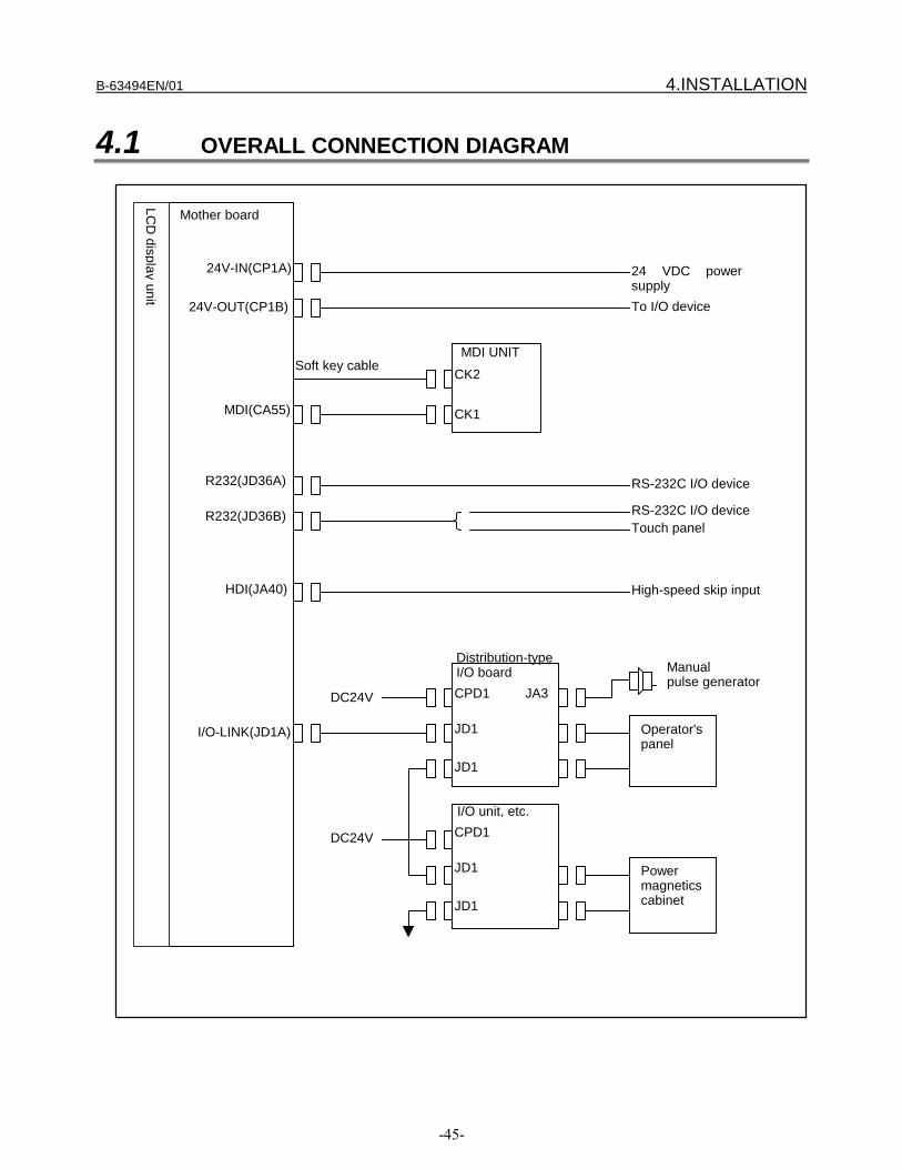
B-63494EN/01 4.INSTALLATION
-45-
4.1 OVERALL CONNECTION DIAGRAM
Mother board
LCD
display unitI/O-LINK(JD1A)
24 VDC powersupply
24V-IN(CP1A)
24V-OUT(CP1B) To I/O device
MDI UNITCK2
CK1
Soft key cable
MDI(CA55)
R232(JD36A)
R232(JD36B)
RS-232C I/O device
RS-232C I/O deviceTouch panel
HDI(JA40) High-speed skip input
Distribution-typeI/O boardCPD1
JD1
JD1
JA3
Operator'spanel
I/O unit, etc.CPD1
JD1
JD1
Powermagneticscabinet
DC24V
DC24V
Manualpulse generator

4.INSTALLATION B-63494EN/01
-46-
Mother board
LCD
display unit
SPDL(JA41) JA7B
JA7A
JY2
TB2
Spindle motorSecond spindle
FSSB(COP10A) Axis 1servo motor
COP10B
COP10A
TB2
JF1
SPM
SVM
COP10B
COP10A
TB2
JF1SVMAxis 2servo monitor
COP10B
COP10A
TB2
JF1SVMAxis 3servo motor
COP10B
COP10A
JF101
JF102
Six or eight axes maximum, depending on the model(This diagram assumes the use of a 1-axis amplifier.)
JF103
JF104
JA4A
Linear scale axis 1
Linear scale axis 2
Linear scale axis 3
Linear scale axis 4
Battery for absoluteposition detector
Separate detector interface unit
COP10B
COP10A
CB155A
CB156A
FSSB I/O
CP11A
CP11APowermagneticscabinet
DC24V
DC24V
SV-CHK(CA54) Servo check board

B-63494EN/01 4.INSTALLATION
-47-
4.2 DI/DO CONNECTION (VIA THE PMC)
For DI/DO signals connected via the PMC, the I/O signals of the unitconnected to the FANUC I/O Link are to be input to or output fromthe following addresses, via the PMC:
PMC→CNC
G008 *ESPG
PMC→CNC#7 #6 #5 #4 #3 #2 #1 #0
G191 *SMC1 GDL1 SGD1 ORQ OPT
CNC→PMC#7 #6 #5 #4 #3 #2 #1 #0
F191 RQT MCF1 *LGD
For the meaning of each of the above signals, see Chapter 6,"OPERATION."Hatted signals means dual monitoring.
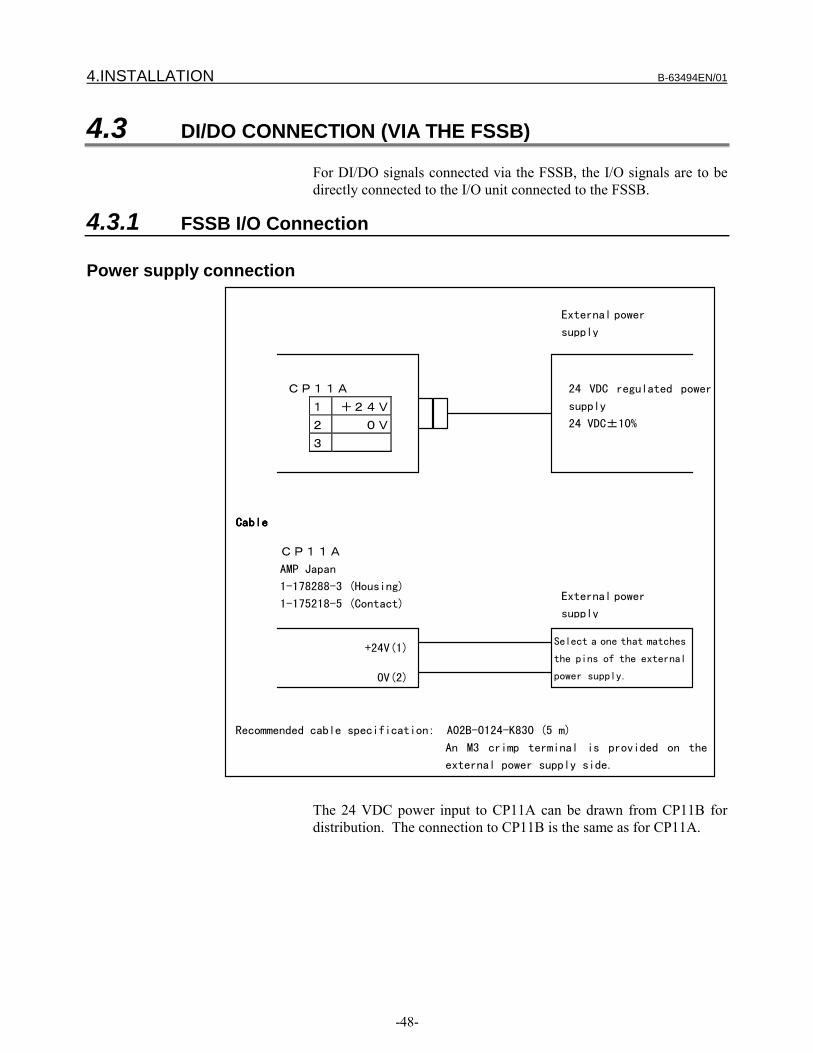
4.INSTALLATION B-63494EN/01
-48-
4.3 DI/DO CONNECTION (VIA THE FSSB)
For DI/DO signals connected via the FSSB, the I/O signals are to bedirectly connected to the I/O unit connected to the FSSB.
4.3.1 FSSB I/O Connection
Power supply connection
CP11A
AMP Japan
1-178288-3 (Housing)
1-175218-5 (Contact)
0V(2)
+24V(1)
External power
supply
External power
supply
CP11A
1 +24V
2 0V
3
Select a one that matches
the pins of the external
power supply.
24 VDC regulated power
supply
24 VDC±10%
CableCableCableCable
Recommended cable specification: A02B-0124-K830 (5 m)
An M3 crimp terminal is provided on the
external power supply side.
The 24 VDC power input to CP11A can be drawn from CP11B fordistribution. The connection to CP11B is the same as for CP11A.

B-63494EN/01 4.INSTALLATION
-49-
DI/DO connection
RV
RV
RV
RV
RV
RV
RV
RV
+24VCB155A(A01)
CB155A(B01)
CB155A(A02)
Pin No.
*ESP2
SMC2
GDL2
SGD2
Signal name
CB155A(A07)
CB155A(B07)
CB155A(A08)
CB155A(B08)
CB155A(A09)
CB155A(B09)
CB155A(A10)
DOCOMCB155A(B06)
CB155A(A11)
Pin No.
Signal name
DV
+24V regulated
power supply
+24V 0V
Relay
DVMCF2
CB155A(A17,B17)
CB155A(B11)Relay
For the meanings of the above signals, see Chapter 6,"OPERATION."
4.3.2 FSSB I/O Attachment
External dimensions

4.INSTALLATION B-63494EN/01
-50-
CP11A
CP11B
Upper:CB156ALower:CB155A
COP10A COP10B
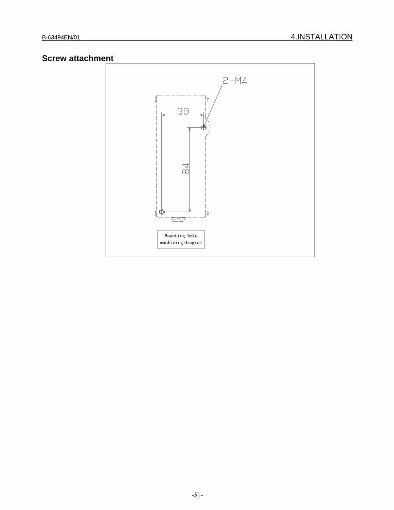
B-63494EN/01 4.INSTALLATION
-51-
Screw attachment
Mounting hole
machining diagram
付穴加
4.INSTALLATION B-63494EN/01
-52-
CAUTIONWhen attaching/detaching this unit, a screwdriver isinserted at an angle. So, a sufficiently large workingspace must be provided on the both sides of thisunit.
As a guideline, if the front surface of an adjacent unitis flush with or set back from the front surface of thisunit, provide about 20 mm between the adjacentunit and this unit. If the front surface of the adjacentstands forward of the front surface of this unit,provide about 70 mm between the adjacent unit andthis unit.
When installing this unit near the side of the cabinet,provide about 70 mm between this unit and thecabinet.

B-63494EN/01 4.INSTALLATION
-53-
Working space around the I/O unit
Attachment to a DIN rail

4.INSTALLATION B-63494EN/01
-54-
Detachment
Attachment
DIN rail
DIN rail
Attachment1. Hook the unit over the top of the DIN rail.2. Press the unit down until it snaps into place.
Detachment1. Pull down the lock section with a standard screwdriver.2. Pull the lower part of the unit toward you.
CAUTIONWhen detaching the unit, be careful not to damagethe lock section by applying excessive force.
When attaching or detaching the unit, hold the upperand lower parts of the unit, if possible, to preventforce from being applied to the side (where thecooling rents are provided) of the unit.

B-63494EN/01 4.INSTALLATION
-55-
4.3.3 FSSB I/O Specification List
Installation conditionsAmbient temperature
of the unitOperating 0~55Storage, transportation -20~60
Temperature variation 1.1/minute maximumHumidity Normally Relative humidity 75% or less
Short term (no more than one month) Relative humidity 95% or lessVibration Operating 0.5G or less
Atmosphere Normal machining plant environment (Check is required if the unit is to be usedin an environment exposed to relatively high levels of dust or coolant, or arelatively high concentration of organic solvents.)
Other conditions (1) Use the unit in a completely sealed cabinet.(2) Install the unit on a vertical surface, and provide a space of 100 mm or more
above and below the unit. Do not install equipment that dissipates muchheat under this unit.
Power supply capacitySupply voltage Power supply
capacityRemarks
24V±10% is fed from the CP11A connector of the basicmodule.±10% includes momentary variations and ripples.
0.3A+7.3mAxDI Number of DI points inDI = ON state
Input signal specificationsContact capacity 30 VDC, 16 mA or more
Leakage current betweenopen contacts
1 mA or less (when the voltage is 26.4 V)
Voltage drop across closedcontacts
2 V or less (including a cable voltage decrease)
Delay time Receiver delay time: 2 ms (MAX)In addition, the FSSB transfer period and ladder scan period need to beconsidered.
Output signal specificationsMaximum load current at ON
time200 mA or less including momentary variations
Saturation voltage at ONtime
1 V (MAX) when the load current is 200 mA
Dielectric voltage 24 V +20% or less including momentary variationsOutput leakage current at
OFF time20 μA or less
Delay time Driver delay time: 50 μs(MAX)In addition, the FSSB transfer period and ladder scan period must beconsidered.

5.I/O SIGNALS B-63494EN/01
-56-
I/O SIGNALS

B-63494EN/01 5.I/O SIGNALS
-57-
5.1 Overview
The dual-check safety system provides two input paths and two outputpaths for safety-related signals (safety signals).For input signals (safety input signals), two paths are used: one pathfor input to the CNC via the PMC, and the other for input to themonitor via the FSSB. The CNC and monitor exchange the safetyinput signals with each other at all times to check each other. If amismatch is found between a safety input signal via one path and thesame signal via the other path, the signal is assumed to be 0. If such astate lasts for the period set in a parameter or more, the CNC andmonitor independently detect an alarm. (Dual-check for safety inputsignals)For output signals (safety output signals), two paths are used: onepath for output from the CNC via the PMC, and the other for outputfrom the monitor via the FSSB. The MCC-on enable signal (MCF) isoutput via these two paths. When both a signal via one path and thesame signal via the other path are 1, the signal is assumed to be 1. Ifeither is 0, the signal is assumed to be 0. That is, if the MCC-onenable signal (MCF) via the PMC and the same signal via the FSSBare both 1, the MCC may be turned on. If either is 0, the MCC mustbe turned off.
In Subsection 5.2, a signal name is followed by its symbol andaddresses <via PMC> and <via FSSB>. Then, for an input signal, itsclassification, function, and operation are described, in this order. Foran output signal, its classification, function, and output condition aredescribed in this order.
For information about the emergency stop mode, MCC off Test mode,and safety signal modes A/B/C/D described in Subsection 5.2, seeSubsection 5.2.2.
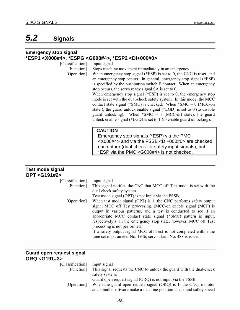
5.I/O SIGNALS B-63494EN/01
-58-
5.2 Signals
Emergency stop signal*ESP1 <X008#4>, *ESPG <G008#4>, *ESP2 <DI+000#0>
[Classification] Input signal[Function] Stops machine movement immediately in an emergency.
[Operation] When emergency stop signal (*ESP) is set to 0, the CNC is reset, andan emergency stop occurs. In general, emergency stop signal (*ESP)is specified by the pushbutton switch B contact. When an emergencystop occurs, the servo ready signal SA is set to 0.When emergency stop signal (*ESP) is set to 0, the emergency stopmode is set with the dual-check safety system. In this mode, the MCCcontact state signal (*SMC) is checked. When *SMC = 0 (MCC-onstate ), the guard unlock enable signal (*LGD) is set to 0 (to disableguard unlocking). When *SMC = 1 (MCC-off state), the guardunlock enable signal (*LGD) is set to 1 (to enable guard unlocking).
CAUTIONEmergency stop signals (*ESP) via the PMC<X008#4> and via the FSSB <DI+000#0> are checkedeach other (dual-check for safety input signals), but*ESP via the PMC <G008#4> is not checked.
Test mode signalOPT <G191#2>
[Classification] Input signal[Function] This signal notifies the CNC that MCC off Test mode is set with the
dual-check safety system.Test mode signal (OPT) is not input via the FSSB.
[Operation] When test mode signal (OPT) is 1, the CNC performs safety outputsignal MCC off Test processing. (MCC-on enable signal (MCF) isoutput in various patterns, and a test is conducted to see if anappropriate MCC contact state signal (*SMC) pattern is input,respectively.) In the emergency stop state, however, MCC off Testprocessing is not performed.If a safety output signal MCC off Test is not completed within thetime set in parameter No. 1946, servo alarm No. 488 is issued.
Guard open request signalORQ <G191#3>
[Classification] Input signal[Function] This signal requests the CNC to unlock the guard with the dual-check
safety system.Guard open request signal (ORQ) is not input via the FSSB.
[Operation] When the guard open request signal (ORQ) is 1, the CNC, monitorand spindle software make a machine position check and safety speed
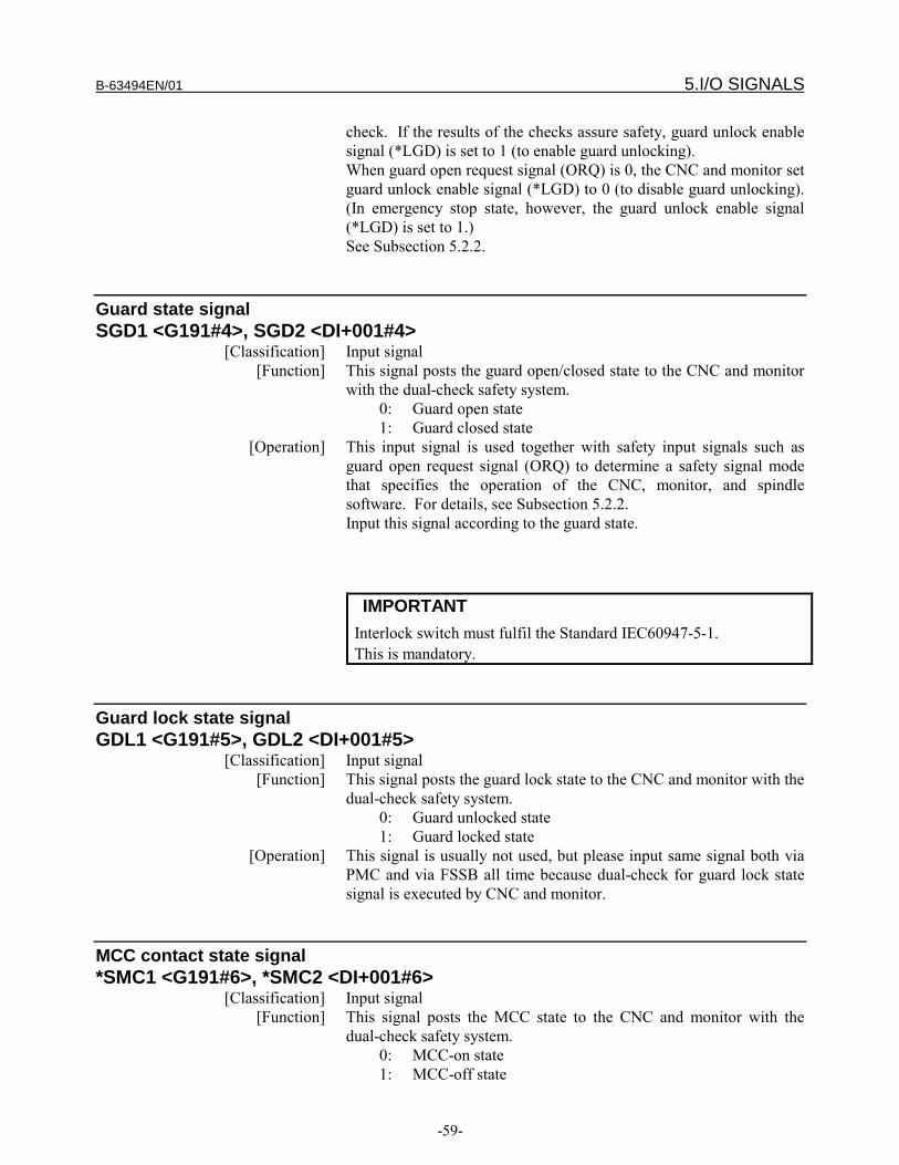
B-63494EN/01 5.I/O SIGNALS
-59-
check. If the results of the checks assure safety, guard unlock enablesignal (*LGD) is set to 1 (to enable guard unlocking).When guard open request signal (ORQ) is 0, the CNC and monitor setguard unlock enable signal (*LGD) to 0 (to disable guard unlocking).(In emergency stop state, however, the guard unlock enable signal(*LGD) is set to 1.)See Subsection 5.2.2.
Guard state signalSGD1 <G191#4>, SGD2 <DI+001#4>
[Classification] Input signal[Function] This signal posts the guard open/closed state to the CNC and monitor
with the dual-check safety system.0: Guard open state1: Guard closed state
[Operation] This input signal is used together with safety input signals such asguard open request signal (ORQ) to determine a safety signal modethat specifies the operation of the CNC, monitor, and spindlesoftware. For details, see Subsection 5.2.2.Input this signal according to the guard state.
IMPORTANTInterlock switch must fulfil the Standard IEC60947-5-1.This is mandatory.
Guard lock state signalGDL1 <G191#5>, GDL2 <DI+001#5>
[Classification] Input signal[Function] This signal posts the guard lock state to the CNC and monitor with the
dual-check safety system.0: Guard unlocked state1: Guard locked state
[Operation] This signal is usually not used, but please input same signal both viaPMC and via FSSB all time because dual-check for guard lock statesignal is executed by CNC and monitor.
MCC contact state signal*SMC1 <G191#6>, *SMC2 <DI+001#6>
[Classification] Input signal[Function] This signal posts the MCC state to the CNC and monitor with the
dual-check safety system.0: MCC-on state1: MCC-off state

5.I/O SIGNALS B-63494EN/01
-60-
[Operation] When the MCC contact state signal (*SMC) is 1 in the emergencystop state, the CNC sets the guard unlock enable signal (*LGD) to 1(to enable guard unlocking).The MCC contact state signal (*SMC) is used to check if the MCC-onenable signal (MCF) operates normally in MCC off Test mode.Input this signal according to the MCC state.
Guard unlock enable signal*LGD <F191#0>
[Classification] Output signal[Function] This signal notifies that guard unlocking is enabled with the dual-
check safety system.When guard unlock enable signal (*LGD) is 0, the guard is locked.When *LGD is 1, the guard is unlocked.Guard unlock enable signal (*LGD) is not output via the FSSB.
[Output condition] In the following cases, this signal is set to 1 (to enable guardunlocking):・ When emergency stop state is set, and MCC contact state signal
(*SMC) is 1 (MCC-off state)・ When guard open request signal (ORQ) is 1, the servo and spindle
motors rotate within the safety speeds, the machine is positionedwithin the safety area, and MCC off Test execution request signal(RQT) is 0
In cases other than the above, this signal is set to 0 (to disable guardunlocking).
MCC-on enable signalMCF1 <F191#1>,MCF2 <DO+000#1>
[Classification] Output signal[Function] This signal posts notification that the MCC can be turned on with the
dual-check safety system.When MCC-on enable signal (MCF) is 0, the MCC is turned off.When MCF is 1, the MCC is turned on.
[Output condition] In the following cases, this signal is set to 0 (to prevent the MCC frombeing turned on):・ When a safety-related alarm is issued・ When the emergency stop state is issuedIn cases other than above, this signal is state to 1 (to enable the MCCto be turned on).
MCC off Test execution request signalRQT <F191#2>
[Classification] Output signal[Function] This signal requests that MCC off Test mode be set, and a check is
made to determine whether the safety output signals (MCC-on enablesignal (MCF)) operate normally. When MCC off Test execution

B-63494EN/01 5.I/O SIGNALS
-61-
request signal (RQT) is set to 1, set MCC off Test mode and conducta safety output signal MCC off Test as soon as possible.When MCC off Test execution request signal (RQT) is 1, guardunlock enable signal (*LGD) is set to 0 to disable guard unlockingeven if safety signal mode B (state in which a guard open request isinput, and the guard is closed) is set and the conditions includingspeed are satisfied.When safety signal mode C (state where a guard open request is input,and the guard is open) is set, and MCC off Test execution requestsignal (RQT) is set to 1, guard unlock enable signal (*LGD) is 0 todisable guard unlocking until MCC off Test execution request signal(RQT) is set to 0 after the guard is closed once.When MCC off Test execution request signal (RQT) is 1, the warning"PLEASE EXECUTE SAFE TEST" is displayed on a screen such asa parameter screen. (On some screens, no warning is displayed.)MCC off Test execution request signal (RQT) is not output via theFSSB.
[Output condition] In the following cases, this signal is set to 1:・ A MCC off Test is not completed after power-on (when bit 3 of
parameter No. 1902 is 0).・ Twenty-four hours have elapsed since the completion of the last
MCC off Test.
CAUTION1. If the current date and time lags behind the date and time of
the previously completed MCC off Test due to a clock changeor the like, it is assumed that 24 hours have elapsed since theprevious MCC off Test.
2. From February 28 to March 1, the elapse of 24 hours may beassumed even if 24 hours has not elapsed after the completionof the previous MCC off Test.
3. MCC must have forced guided contacts and must fulfil theStandard IEC60204 and the standard IEC 255.This ismandatory.
In the following case, this signal is set to 0:・ A MCC off Test is completed.
5.2.1 Signal Addresses
Via the PMC#7 #6 #5 #4 #3 #2 #1 #0
X008 *ESP1
#7 #6 #5 #4 #3 #2 #1 #0
G008 *ESPG
#7 #6 #5 #4 #3 #2 #1 #0

5.I/O SIGNALS B-63494EN/01
-62-
G191 *SMC1 GDL1 SGD1 ORQ OPT
#7 #6 #5 #4 #3 #2 #1 #0
F191 RQT MCF1 *LGD
Via the FSSB#7 #6 #5 #4 #3 #2 #1 #0
DI+0000 *ESP2
#7 #6 #5 #4 #3 #2 #1 #0
DI+001 *SMC2 GDL2 SGD2
#7 #6 #5 #4 #3 #2 #1 #0
DO+000 MCF2
CAUTIONEmergency stop signals (*ESP) via the PMC<X008#4> and via the FSSB <DI+000#0> are checkedeach other (dual-check for safety input signals), but*ESP via the PMC <G008#4> is not checked.
5.2.2 Safety Signal ModesDepending on the safety input signal state, the CNC, monitor, andspindle software internally have one of the six modes (safety signalmodes) indicated in the table below.
Safety signal mode Safety signal state Machine stateEmergency stop mode *ESP = 0 Emergency stop stateMCC off Test mode OPT = 1 State for conducting a MCC
off TestSafety signal mode A ORQ = 0 and SGD = 1 Normal operation stateSafety signal mode B ORQ = 1, and SGD = 1 State in which a guard open
request is input, and theguard is closed
Safety signal mode C ORQ = 1, and SGD = 0 State in which a guard openrequest is input, and theguard is open
Safety signal mode D ORQ = 0 and SGD = 0 Abnormal state (state inwhich the guard is openalthough no guard openrequest is input.)
In general, safety signal mode transitions are made as describedbelow.Usually, safety signal mode A is set. In safety signal mode A, guardunlock enable signal (*LGD) is 0, and the guard is locked.When an emergency stop is required, emergency stop mode is set. Inemergency stop mode, the MCC contact state signal (*SMC) ischecked. When *SMC = 0 (MCC-on state), guard unlock enable

B-63494EN/01 5.I/O SIGNALS
-63-
signal (*LGD) is set to 0 (to disable guard unlocking). When *SMC= 1 (MCC-off state), guard unlock enable signal (*LGD) is set to 1 (toenable guard unlocking).When a MCC off Test is to be conducted, MCC off Test mode is set.In MCC off Test mode, safety output signal MCC off Test processingis performed. (MCC-on enable signal (MCF) are output in variouspatterns, and a test is conducted to determine whether appropriateMCC contact state signal (*SMC) patterns are input respectively.)When the guard is to be opened, safety signal mode B is set. In safetysignal mode B, the CNC, monitor, and spindle software check themachine position and the speed on each axis. If safety is assured,guard unlock enable signal (*LGD) is set to 1 to enable the guard tobe opened.When the guard is opended in safety signal mode B after guard unlockenable signal (*LGD) is set to 1, safety signal mode C is set. In safetysignal mode C, the CNC, monitor, and spindle software check themachine position and the speed on each axis. If an abnormality isdetected, an alarm is issued, MCC-on enable signal (MCF) is set to 0,and the MCC is turned off.Safety signal mode D represents an abnormal state in which the guardis open although no guard open request is made. In safety signalmode D, an alarm is issued, the MCC-on enable signal (MCF) is set to0, and the MCC is turned off.

6.PARAMETERS B-63494EN/01
-64-
PARAMETERS

B-63494EN/01 6.PARAMETERS
-65-
6.1 OverviewThe parameters related to the dual-check safety function (safetyparameters) are protected by a code (No. 3225) for the safetyparameters. The value of a safety parameter cannot be modifiedunless the same value as the code for the safety parameters is set asthe key (No. 3226) for the safety parameters.The safety parameters are stored in two locations on the CNC. TheCNC, monitor, and spindle software check the matching of theparameters stored at the two locations. If a mismatch is found, analarm is issued.
If the setting of a safety parameter is modified, the power must beturned off then back on. The new setting of the parameter becomeseffective after the power is turned back on.
For information about emergency stop mode, MCC off Test mode,and safety signal modes A/B/C/D described in this section, seeSection 6.

6.PARAMETERS B-63494EN/01
-66-
6.2 Parameters
1023 Servo axis number for each axis[Data type] Byte axis
[Valid data range] 1, 2, 3, ..., number of controlled axesSet which servo axis corresponds to each controlled axis. Usually, setthe same value for a controlled axis number and servo axis number.A controlled axis number represents an array number for an axis typeparameter or axis type machine signal.For details of the setting, refer to the description of FSSB setting inthe connection manual (function part).
1829 Positional deviation limit during a stop for each axis[Data type] Word axis
[Unit of data] Detection unit[Valid data range] 0 to 32767
Set a positional deviation limit for each axis at stop time.If a positional deviation limit during a stop is exceeded at stop time, aservo alarm is issued, and an immediate stop (same as an emergencystop) is performed.When the dual-check safety function is used, the CNC and monitormake a positional deviation check in safety signal mode C (state inwhich a guard open request is input, and the guard is opened); in theother modes, only the CNC performs a positional deviation check.
1838 Positional deviation limit during movement for each axis in safety signalmode C
[Data type] 2-word axis[Unit of data] Detection unit
[Valid data range] 0 to 99999999Set a positional deviation limit during movement for each axis insafety signal mode C (state in which a guard open request is input,and the guard is opened) when the dual-check safety function is used.If a positional deviation limit during movement is exceeded duringmovement, a servo alarm is issued, and an immediate stop (same as anemergency stop) is performed.When the dual-check safety function is used, the CNC and monitormake a positional deviation check in safety signal mode C (state inwhich a guard open request is input, and the guard is opened); in othermodes, only the CNC makes a positional deviation check.When the guard is open, axis movement is performed at a speed notexceeding the safety speed. So, usually, set a value smaller than apositional deviation limit during movement (parameter No. 1828).
#7 #6 #5 #4 #3 #2 #1 #0
1902 DCE STP[Data type] Bit
STP When the power is turned on, a safety output signal MCC off Test inthe MCC off Test mode is:
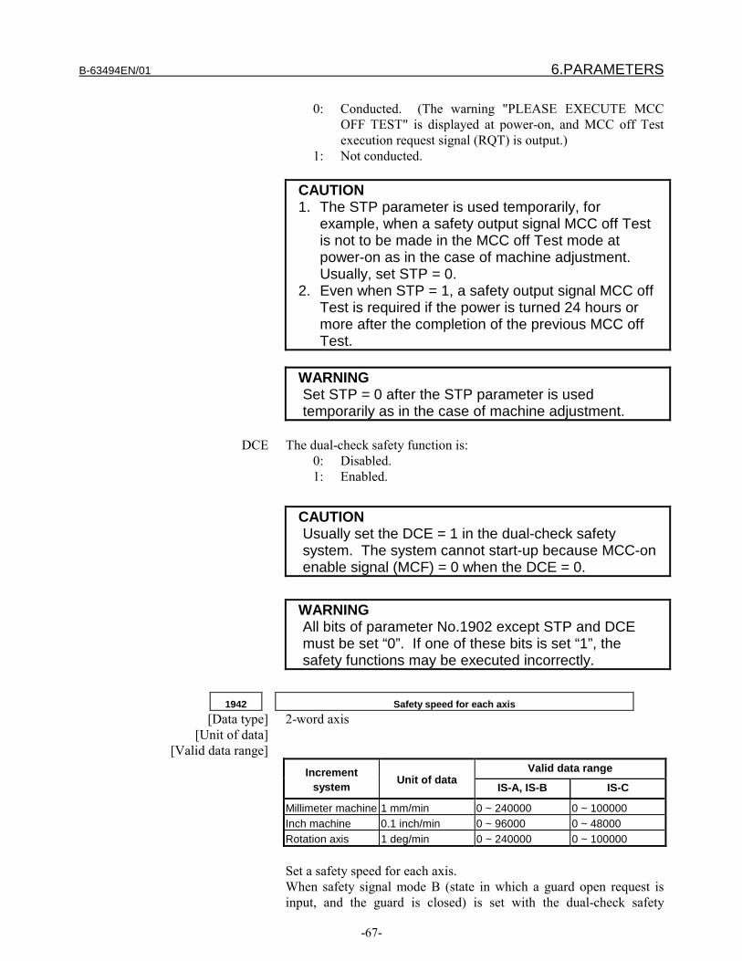
B-63494EN/01 6.PARAMETERS
-67-
0: Conducted. (The warning "PLEASE EXECUTE MCCOFF TEST" is displayed at power-on, and MCC off Testexecution request signal (RQT) is output.)
1: Not conducted.
CAUTION1. The STP parameter is used temporarily, for
example, when a safety output signal MCC off Testis not to be made in the MCC off Test mode atpower-on as in the case of machine adjustment.Usually, set STP = 0.
2. Even when STP = 1, a safety output signal MCC offTest is required if the power is turned 24 hours ormore after the completion of the previous MCC offTest.
WARNINGSet STP = 0 after the STP parameter is usedtemporarily as in the case of machine adjustment.
DCE The dual-check safety function is:0: Disabled.1: Enabled.
CAUTIONUsually set the DCE = 1 in the dual-check safetysystem. The system cannot start-up because MCC-onenable signal (MCF) = 0 when the DCE = 0.
WARNINGAll bits of parameter No.1902 except STP and DCEmust be set “0”. If one of these bits is set “1”, thesafety functions may be executed incorrectly.
1942 Safety speed for each axis[Data type] 2-word axis
[Unit of data][Valid data range]
Valid data rangeIncrementsystem Unit of data
IS-A, IS-B IS-C
Millimeter machine 1 mm/min 0 ~ 240000 0 ~ 100000Inch machine 0.1 inch/min 0 ~ 96000 0 ~ 48000Rotation axis 1 deg/min 0 ~ 240000 0 ~ 100000
Set a safety speed for each axis.When safety signal mode B (state in which a guard open request isinput, and the guard is closed) is set with the dual-check safety

6.PARAMETERS B-63494EN/01
-68-
function, the CNC and monitor check the speed command for eachaxis. If there is at least one axis for which a speed greater than thesafety speed is specified, the guard unlock enable signal (*LGD) is setto 0 to disable guard unlocking. The state in which the speedsspecified for all axes are within the safety speeds is one condition forsetting the guard unlock enable signal (*LGD) to 1 (to enable guardunlocking).In safety signal mode C (state in which a guard open request is input,and the guard is open), the CNC and monitor check the speedcommand for each axis. If there is at least one axis for which a speedgreater than the safety speed is specified, a servo alarm is issued.
1943 Safety position of each axis (+ direction)
1944 Safety position of each axis (- direction)[Data type] 2-word
[Unit of data]Increment system IS-A IS-B IS-C UnitMillimeter machine 0.01 0.001 0.0001 mmInch machine 0.001 0.0001 0.00001 inch
[Valid data range] -99999999 to 99999999Set a safety position for each axis.When safety signal mode B (state in which a guard open request isinput, and the guard is closed) is set with the dual-check safetyfunction, the CNC and monitor check the machine position of eachlinear axis. If there is at least one linear axis whose machine positionis not in the safety position (safety position (- direction) ≤ machineposition ≤ safety position (+ direction)), the guard unlock enablesignal (*LGD) is set to 0 to disable guard unlocking. The state inwhich the machine positions of all linear axes are within the safetypositions is one condition for setting the guard unlock enable signal(*LGD) to 1 (to enable guard unlocking).In safety signal mode C (state in which a guard open request is input,and the guard is open), the CNC and monitor check the machineposition of each linear axis. If there is at least one linear axis whosemachine position is not in the safety position, a servo alarm is issued.
WARNINGCNC and monitor check the machine position of eachlinear axis, and not check it of each rotation axis.
WARNINGCNC and monitor check the machine position of onlyeach axis whose reference position is established, andnot check it of each axis whose reference position isnot established.
1945 Safety input signal check timer[Data type] Word
[Unit of data] ms
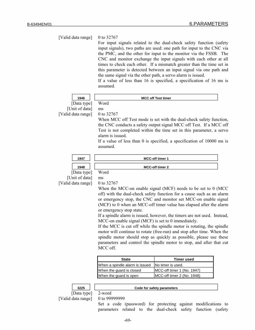
B-63494EN/01 6.PARAMETERS
-69-
[Valid data range] 0 to 32767For input signals related to the dual-check safety function (safetyinput signals), two paths are used: one path for input to the CNC viathe PMC, and the other for input to the monitor via the FSSB. TheCNC and monitor exchange the input signals with each other at alltimes to check each other. If a mismatch greater than the time set inthis parameter is detected between an input signal via one path andthe same signal via the other path, a servo alarm is issued.If a value of less than 16 is specified, a specification of 16 ms isassumed.
1946 MCC off Test timer[Data type] Word
[Unit of data] ms[Valid data range] 0 to 32767
When MCC off Test mode is set with the dual-check safety function,the CNC conducts a safety output signal MCC off Test. If a MCC offTest is not completed within the time set in this parameter, a servoalarm is issued.If a value of less than 0 is specified, a specification of 10000 ms isassumed.
1947 MCC-off timer 1
1948 MCC-off timer 2[Data type] Word
[Unit of data] ms[Valid data range] 0 to 32767
When the MCC-on enable signal (MCF) needs to be set to 0 (MCCoff) with the dual-check safety function for a cause such as an alarmor emergency stop, the CNC and monitor set MCC-on enable signal(MCF) to 0 when an MCC-off timer value has elapsed after the alarmor emergency stop state.If a spindle alarm is issued, however, the timers are not used. Instead,MCC-on enable signal (MCF) is set to 0 immediately.If the MCC is cut off while the spindle motor is rotating, the spindlemotor will continue to rotate (free-run) and stop after time. When thespindle motor should stop as quickly as possible, please use theseparameters and control the spindle motor to stop, and after that cutMCC off.
State Timer usedWhen a spindle alarm is issued No timer is used.When the guard is closed MCC-off timer 1 (No. 1947)When the guard is open MCC-off timer 2 (No. 1948)
3225 Code for safety parameters[Data type] 2-word
[Valid data range] 0 to 99999999Set a code (password) for protecting against modifications toparameters related to the dual-check safety function (safety

6.PARAMETERS B-63494EN/01
-70-
parameters). When a code for safety parameters is set, the parametersare locked. At this time, the setting (code) is not displayed but isblank, and safety parameter input is disabled. If an attempt is made toinput data in a locked safety parameter, the result indicated in thetable below is produced, depending on the method of input. Noattempt is successful.
Input method ResultMDI input Warning "WRITE PROTECT"G10 (programmable parameter input) P/S231 FORMAT ERROR IN G10
L50Input via the reader/punch interface No alarm is issued, but parameter
input is disabled.Input through a window Completion code 7 (write protect)
A code for safety parameters can be set when the safety parametersare not locked, that is, when the code for safety parameters is 0, orwhen the code for safety parameters is the same as the key for safetyparameters (No. 3226).The following safety parameters are protected by a code for safetyparameters:No.1023, No.1829, No.1838, No.1902 #3, No.1902 #6, No.1942,No.1943, No.1944, No.1945, No.1946, No.1947, No.1948, No.3225,No.4372
3226 Key for safety parameters[Data type] 2-word
[Valid data range] 0 to 99999999When the same value as the code for safety parameters is set in thisparameter, the key is opened to enable modifications to the safetyparameters. The value set in this parameter is not displayed. Whenthe power is turned off, the value set in this parameter is cleared,resulting in the locked state.
CAUTIONOnce a key is set, the key must be cancelled ormemory must be cleared before the safety parameterscan be modified. Moreover, the code for the safetyparameters cannot be modified. Be careful whensetting a code for safety parameters.
4372 Safety speed of each spindle[Data type] Word
[Unit of data] min-1
[Valid data range] 0 to 32767Set a safety speed for each spindle in terms of motor speed.When safety signal mode B (state in which a guard open request isinput, and the guard is closed) is set with the dual-check safetyfunction, the CNC and spindle software check the speed of eachspindle motor. If there is at least one spindle whose speed is greater

B-63494EN/01 6.PARAMETERS
-71-
than the safety speed, guard unlock enable signal (*LGD) is set to 0 todisable guard unlocking. The state in which the speeds of all spindlemotors are within the safety speeds is one condition for setting guardunlock enable signal (*LGD) to 1 (to enable guard unlocking).When safety signal mode C (state in which a guard open request isinput, and the guard is open) is set, the CNC and spindle softwarecheck the speed of each spindle motor. If there is at least one spindlewhose speed is greater than the safety speed, a spindle alarm is issued.

7.MAINTENANCE B-63494EN/01
-72-
MAINTENANCE
B-63494EN/01 7.MAINTENANCE
-73-
7.1 SAFETY PRECAUTIONSThis section describes the safety precautions related to the use ofCNC units. It is essential that these precautions be observed by usersto ensure the safe operation of machines equipped with a CNC unit(all descriptions in this section assume this configuration).CNC maintenance involves various dangers. CNC maintenance mustbe undertaken only by a qualified technician.Users must also observe the safety precautions related to the machine,as described in the relevant manual supplied by the machine toolbuilder.Before checking the operation of the machine, take time to becomefamiliar with the manuals provided by the machine tool builder andFANUC.
CAUTIONMaintenance on a live system requires careful planning, adherenceto operating and maintenance procedures, and the appropriatepermits and permissions.These matters are the responsibility of the owner/operator of thesystem and are outside the scope of this document.
TRAININGFANUC Training Center provides versatile training course for theperson who is concerned with hardware and software installation,maintenance and operation. FANUC recommend studying andlearning how efficiently operate FANUC products.
QUALIFIED PERSONNELOnly qualified personnel should be allowed to specify, apply, install,
commissioning, operate, maintain, or perform any other functionrelated to the products described in the product manuals.Examples of such qualified persons are defined as follows:
— System application and design engineers who are familiar with thesafety concepts of machine tool.
— Installation, startup, and service personnel who are trained toinstall and maintain such machine tool.
— Operating personnel trained to operate machine tool and trainedon the specific safety issues and requirements of the particularequipment.
MAINTENANCE PARTS TO BE MAINTAINED PERIODICALLY
− Memory backup battery replacement
WARNINGWhen replacing the memory backup batteries, keep the power to themachine (CNC) turned on, and apply an emergency stop to themachine. Because this work is performed with the power on and thecabinet open, only those personnel who have received approved safetyand maintenance training may perform this work.

7.MAINTENANCE B-63494EN/01
-74-
When replacing the batteries, be careful not to touch the high–voltagecircuits (marked and fitted with an insulating cover).Touching the uncovered high–voltage circuits presents an extremelydangerous electric shock hazard.
NOTEThe CNC uses batteries to preserve the contents of its memory,because it must retain data such as programs, offsets, and parameterseven while external power is not applied.If the battery voltage drops, a low battery voltage alarm is displayedon the machine operator’s panel or CRT screen.When a low battery voltage alarm is displayed, replace the batterieswithin a week. Otherwise, the contents of the CNC’s memory will belost.To replace the battery, see the procedure described in Section 2.10of the maintenance manual B-63005EN/01.
WARNINGS RELATED TO CHECK OPERATIONWARNING1. When checking the operation of the machine with the coverremoved(1) The user’s clothing could become caught in the spindle or othercomponents, thus presenting a danger of injury. When checking theoperation, stand away from the machine to ensure that your clothingdoes not become tangled in the spindle or other components.(2) When checking the operation, perform idle operation withoutworkpiece. When a workpiece is mounted in the machine, amalfunction could cause the workpiece to be dropped or destroy thetool tip, possibly scattering fragments throughout the area. Thispresents a serious danger of injury. Therefore, stand in a safe locationwhen checking the operation.
2. When checking the machine operation with the power magneticscabinet door opened.(1) The power magnetics cabinet has a high–voltage section (carryinga mark). Never touch the high–voltage section. The high–voltagesection presents a severe risk of electric shock. Before starting anycheck of the operation, confirm that the cover is mounted on the high–voltage section. When the high–voltage section itself must bechecked, note that touching a terminal presents a severe danger ofelectric shock.(2) Within the power magnetics cabinet, internal units presentpotentially injurious corners and projections. Be careful whenworking inside the power magnetics cabinet.
3. Never attempt to machine a workpiece without first checking theoperation of the machine.Before starting a production run, ensure that the machine is operatingcorrectly by performing a trial run using, for example, the single
B-63494EN/01 7.MAINTENANCE
-75-
block, feedrate override, or machine lock function or by operating themachine with neither a tool nor workpiece mounted. Failure toconfirm the correct operation of the machine may result in themachine behaving unexpectedly, possibly causing damage to theworkpiece and/or machine itself, or injury to the user.
4. Before operating the machine, thoroughly check the entered data.Operating the machine with incorrectly specified data may result inthe machine behaving unexpectedly, possibly causing damage to theworkpiece and/or machine itself, or injury to the user.
5. Ensure that the specified feedrate is appropriate for the intendedoperation. Generally, for each machine, there is a maximum allowablefeedrate. The appropriate feedrate varies with the intended operation.Refer to the manual provided with the machine to determine themaximum allowable feedrate. If a machine is run at other than thecorrect speed, it may behave unexpectedly, possibly causing damageto the workpiece and/or machine itself, or injury to the user.
6. When using a tool compensation function, thoroughly check thedirection and amount of compensation.Operating the machine with incorrectly specified data may result inthe machine behaving unexpectedly, possibly causing damage to theworkpiece and/or machine itself, or injury to the user.
WARNINGS RELATED TO REPLACEMENTWARNING1. Always turn off the power to the CNC and the main power to thepower magnetics cabinet. If only the power to the CNC is turned off,power may continue to be supplied to the serve section.In such a case, replacing a unit may damage the unit, while alsopresenting a danger of electric shock.
2. When a heavy unit is to be replaced, the task must be undertakenby two persons or more. If the replacement is attempted by only oneperson, the replacement unit could slip and fall, possibly causinginjury.
3. After the power is turned off, the servo amplifier and spindleamplifier may retain voltages fora while, such that there is a danger ofelectric shock even while the amplifier is turned off. Allow at leasttwenty minutes after turning off the power for these residual voltagesto dissipate.
4. When replacing a unit, ensure that the new unit has the sameparameter and other settings as the old unit. (For details, refer to themanual provided with the machine.) Otherwise, unpredictablemachine movement could damage the workpiece or the machine itself,and present a danger of injury.
7.MAINTENANCE B-63494EN/01
-76-
5. After replacing a safety related unit such as encoder and I/O
module, conduct a check test on the safety related and
record the test results in a check report.
WARNINGS RELATED TO PARAMETERSWARNING1. When machining a workpiece for the first time after modifying aparameter, close the machine cover. Never use the automaticoperation function immediately after such a modification.Instead, confirm normal machine operation by using functions such asthe single block function, feedrate override function, and machinelock function, or by operating the machine without mounting a tooland workpiece. If the machine is used before confirming that itoperates normally, the machine may move unpredictably, possiblydamaging the machine or workpiece, and presenting a risk of injury.
2. The CNC and PMC parameters are set to their optimal values, sothat those parameters usually need not be modified. When a parametermust be modified for some reason, ensure that you fully understandthe function of that parameter before attempting to modify it. If aparameter is set incorrectly, the machine may move unpredictably,possibly damaging the machine or workpiece, and presenting a risk ofinjury.

B-63494EN/01 7.MAINTENANCE
-77-
7.2 AlarmsAlarms related to the dual-check safety function cannot be cancelledby a reset. To cancel the alarms, turn off the power.
For information about emergency stop mode, MCC off Test mode,and safety signal modes A/B/C/D, see Section 6.
7.2.1 Servo Alarms
No. Meaning Description Remedy364 n AXIS: SOFT PHASE
ALARM(INT)The servo control softwaredetected an abnormal data skipin a velocity feedback signal onaxis n (axis 1 to axis 8).
Replace the alpha pulse coder,or take measures to correctnoise on the feedback cable.
403 SERVO ALARM : CARD/SOFTMISMATCH
For the axis control card, thecorrect servo software is notinstalled in flash memory.When the dual-check safetyfunction is used:・ An incorrect axis control card
is mounted.・ Incorrect servo software is
installed in flash memory.・ Monitor software is not
installed in flash memory.
Mount the correct axis controlcard, and install the correctservo software and monitorsoftware in flash memory.
410 SERVO ALARM : n AXISEXCESS ERR
The CNC detected that thepositional deviation during astop on axis n (axis 1 to axis 8)exceeded the setting (parameterNo. 1829).
Confirm a proper valule is set toparameter No. 1829.
411 SERVO ALARM : n AXISEXCESS ERR
The CNC detected that thepositional deviation duringmovement on axis n (axis 1 toaxis 8) exceeded the setting inparameter No. 1828 (parameterNo. 1838 when the safety signalmode C (state wherer a guardopen request is input, and theguard is open) is set with thedual-check safety function).
Confirm a proper value is set toparameter No. 1828 or No.1838.
453 n AXIS:SPC SOFTDISCONNECT ALARM
The servo control softwaredetected an alpha pulse codersignal error on axis n (axis 1 toaxis 8).
Replace the alpha pulse coder.
470 n AXIS:ILLEGAL RAM (MNT) An error occurred in a monitorRAM check.
Replace the axis control card.
471 n AXIS:SPC SOFTDISCONNECT (MNT)
The monitor detected an alphapulse coder signal error on axisn (axis 1 to axis 8).
Replace the alpha pulse coder.
473 n AXIS:SOFT PHASEALARM(INT/MNT)
The monitor detected anabnormal data skip in a velocityfeedback signal on axis n (axis1 to axis 8).
Replace the alpha pulse coder,or take measures to correctnoise on the feedback cable.
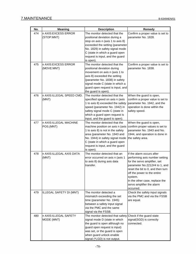
7.MAINTENANCE B-63494EN/01
-78-
No. Meaning Description Remedy474 n AXIS:EXCESS ERROR
(STOP:MNT)The monitor detected that thepositional deviation during astop on axis n (axis 1 to axis 8)exceeded the setting (parameterNo. 1829) in safety signal modeC (state in which a guard openrequest is input, and the guardis open).
Confirm a proper value is set toparameter No. 1828.
475 n AXIS:EXCESS ERROR(MOVE:MNT)
The monitor detected that thepositional deviation duringmovement on axis n (axis 1 toaxis 8) exceeded the setting(parameter No. 1838) in safetysignal mode C (state in which aguard open request is input, andthe guard is open).
Confirm a proper value is set toparameter No. 1838.
476 n AXIS:ILLEGAL SPEED CMD.(MNT)
The monitor detected that thespecified speed on axis n (axis1 to axis 8) exceeded the safetyspeed (parameter No. 1942) insafety signal mode C (state inwhich a guard open request isinput, and the guard is open).
When the guard is open,confirm a proper value is set toparameter No. 1942, and theoperation is done within thesafety speed.
477 n AXIS:ILLEGAL MACHINEPOS.(MNT)
The monitor detected that themachine position on axis n (axis1 to axis 8) is not in the safetyarea (parameter No. 1943 andNo. 1944) in safety signal modeC (state in which a guard openrequest is input, and the guardis open).
When the guard is open,confirm proper values is set toparameter No. 1943 and No.1944, and operation is done inthe safety area.
478 n AXIS:ILLEGAL AXIS DATA(MNT)
The monitor detected that anerror occurred on axis n (axis 1to axis 8) during axis datatransfer.
If the alarm occurs afterperforming axis number settingfor the servo amplifier, setparameter No.2212#4 to 1, andreset the bit to 0, and then turnoff the power to the entiresystem.In the other case, replace theservo amplifier the alarmoccurred.
479 ILLEGAL SAFETY DI (MNT) The monitor detected amismatch exceeding the settime (parameter No. 1945)between a safety input signalvia the PMC and the samesignal via the FSSB.
Check the safety input signalsvia the PMC and via the FSSBare equal.
480 n AXIS:ILLEGAL SAFETYMODE (MNT)
The monitor detected that safetysignal mode D (state in whichthe guard is open although noguard open request is input)was set, or the guard is openwhen guard unlock enablesignal (*LGD) is not output.
Check if the guard statesignal(SGD) is correctlyconnected.

B-63494EN/01 7.MAINTENANCE
-79-
No. Meaning Description Remedy481 n AXIS:SAFETY PARAM
ERROR (MNT)The monitor detected that asafety parameter error occurredwith axis n (axis 1 to axis 8).
Set the safety parametersagain.
482 n AXIS:AXIS NUMBER NOTSET (MNT)
The monitor detected that theaxis number of axis n (axis 1 toaxis 8) is not set with the servoamplifier.
Turn off the power to the entiresystem. Then an axis number isautomatically set.
483 MONITOR SAFETY FUNCTIONERROR
An error occurred in safetyfunctions of monitor:1. Monitor or CNC detected the
inexecution of monitor safetyfunctions.
2. A mismatch between themonitor results of the safetyfunctions and the servosoftware or CNC results ofthem occurred.
3. An error occurred in a monitorCPU test.
Replace the axis control card.
484 n AXIS:SERVO SAFETYFUNCTION ERR
An error occurred in safetyfunctions of servo software:1. Servo software or CNC
detected the inexecution ofservo software safetyfunctions.
2. A mismatch between theservo software results of thesafety functions and themonitor results of themoccurred.
3. An error occurred in a servoRAM test.
4. An error occurred in a servoCPU test.
Replace the axis control card.
486 ILLEGAL SAFETY DI (CNC) The CNC detected a mismatchexceeding the set time(parameter No. 1945) betweena safety input signal input viathe PMC and the same signalinput via the FSSB.
Check the safety input signalsvia the PMC and via the FSSBare equal.
487 ILLEGAL SAFETY MODE(CNC)
The CNC detected that safetysignal mode D (state in whichthe guard is open although noguard open request is input)was set, or the guard is openwhen guard unlock enablesignal (*LGD) is not output.
Check if the guard statesignal(SGD) is correctlyconnected.
488 SAFE TEST OVER TIME A safety output signal MCC offTest in MCC off Test mode wasnot completed within the settime (parameter No. 1946).
Check the MCC contact.
489 SAFETY PARAM ERROR(CNC)
The CNC detected a safetyparameter error.
Set the safety parametersagain.

7.MAINTENANCE B-63494EN/01
-80-
No. Meaning Description Remedy490 CNC SAFETY FUNCTION
ERRORAn error occurred in safetyfunctions of CNC:1. CNC or monitor detected the
inexecution of CNC safetyfunctions.
2. A mismatch between theCNC results of the safetyfunctions and the monitor orspindle results of themoccurred.
3. An error occurred in a servoRAM test.
4. An error occurred in a servoCPU test.
5. CNC MCC off Test at power-up was not executed.
Replace the CPU card.
491 LOCAL BUS TEST ERROR An error occurred in a local bustest. The mother board may befaulty.
Replace the mother board.
492 F-BUS TEST ERROR An error occurred in an F-BUStest. The mother board oroption board may be faulty.
Replace the mother board or theoption board.
494 n AXIS:ILLEGAL SPEED CMD.(CNC)
The CNC detected that thespecified speed on axis n (axis1 to axis 8) exceeded the setting(parameter No. 1942) in safetysignal mode C (state in which aguard open request is input, andthe guard is open).
When the guard is open,confirm a proper value is set toparameter No. 1942, and theoperation is done within thesafety speed.
495 n AXIS:ILLEGAL MACHINEPOS.(CNC)
The CNC detected that themachine position on axis n (axis1 to axis 8) is not in the safetyarea (parameter No. 1943 andNo. 1944) in safety signal modeC (state in which a guard openrequest is input, and the guardis open).
When the guard is open,confirm proper values is set toparameter No. 1943 and No.1944, and operation is done inthe safety area.
496 n AXIS:ILLEGAL AXIS DATA(CNC)
The CNC detected that an erroroccurred on axis n (axis 1 toaxis 8) during axis data transfer.
If the alarm occurs afterperforming axis number settingfor the servo amplifier, setparameter No.2212#4 to 1, andreset the bit to 0, and then turnoff the power to the entiresystem.In the other case, replace theservo amplifier the alarmoccurred.
497 n AXIS:SAFETY PARAMTRANS ERROR
A safety parameter transfererror occurred on axis n (axis 1to axis 8).
Replace the CPU card or theaxis control card.
498 n AXIS:AXIS NUMBER NOTSET (CNC)
The CNC detected that the axisnumber of axis n (axis 1 to axis8) is not set with the servoamplifier.
Turn off the power to the entiresystem. Then an axis number isautomatically set.

B-63494EN/01 7.MAINTENANCE
-81-
7.2.2 Serial Spindle Alarms
No. Meaning Description Remedy749 S-SPINDLE LSI ERROR It is serial communication error
while system is executing afterpower supply on.
Check optical cable connectionbetween main CPU board andspindle amplifier printed board.Replace optical cable, mainCPU board, option 2 board orspindle amplifier printed board.If this alarm occurs when CNCpower supply is turned on orwhen this alarm can not becleared even if CNC is reset,turn off the power supply alsoturn off the power supply inspindle side.
755 SPINDLE-1 SAFETYFUNCTION ERROR
An error occurred in any spindlesafety functions on the firstspindle.1. CNC detected that some
spindle safety functions werenot executed.
2. A safety parameter transfererror occurred.
Replace the CPU card orspindle amplifier module.
756 SPINDLE-1 ILLEGAL AXISDATA
For the first spindle, the CNCdetected a mismatch betweenthe spindle amplifier connectionstate and spindle amplifierhardware setting.
Check the spindlle amplifierconnectoin state and spindleamplifier hardware setting.Replace the CPU card orspindle amplifier module.If this alarm is issued becausethe spindle amplifierconfiguration is changed,correct the setting on thespindle amplifier side.
757 SPINDLE-1 SAFETY SPEEDOVER
For the first spindle, the CNCdetected that the speed of thespindle motor exceeded thesafety speed (parameter No.4372) in safety signal mode C(state in which a guard openrequest is input, and the guardis open).Alternatively, for the firstspindle, the CNC detected amismatch between the CNC andspindle software, as to which ofthe speed of the spindle motorand the safety speed(parameter No. 4372) is greater.
When the guard is open,perform operation at a speednot exceeding the safety speed.Check the safety speedparameter(parameter No.4372).Replace the CPU card orspindle amplifier module.
765 SPINDLE-2 SAFETYFUNCTION ERROR
Same as alarm No. 755. (Forthe second spindle)
Same as alarm No. 755. (Forthe second spindle)
766 SPINDLE-2 ILLEGAL AXISDATA
Same as alarm No. 756. (Forthe second spindle)
Same as alarm No. 756. (Forthe second spindle)

7.MAINTENANCE B-63494EN/01
-82-
No. Meaning Description Remedy767 SPINDLE-2 SAFETY SPEED
OVERSame as alarm No. 757. (Forthe second spindle)
Same as alarm No. 757. (Forthe second spindle)
775 SPINDLE-3 SAFETYFUNCTION ERROR
Same as alarm No. 755. (Forthe third spindle)
Same as alarm No. 755. (Forthe third spindle)
776 SPINDLE-3 ILLEGAL AXISDATA
Same as alarm No. 756. (Forthe third spindle)
Same as alarm No. 756. (Forthe third spindle)
777 SPINDLE-3 SAFETY SPEEDOVER
Same as alarm No. 757. (Forthe third spindle)
Same as alarm No. 757. (Forthe third spindle)
785 SPINDLE-4 SAFETYFUNCTION ERROR
Same as alarm No. 755. (Forthe fourth spindle)
Same as alarm No. 755. (Forthe fourth spindle)
786 SPINDLE-4 ILLEGAL AXISDATA
Same as alarm No. 756. (Forthe fourth spindle)
Same as alarm No. 756. (Forthe fourth spindle)
787 SPINDLE-4 SAFETY SPEEDOVER
Same as alarm No. 757. (Forthe fourth spindle)
Same as alarm No. 757. (Forthe fourth spindle)
7n16 SPN n :S-SPINDLE ERROR(AL-16)
See the description of AL-16 inSubsection 7.2.3. (For the n-thspindle)
See the description of AL-16 inSubsection 7.2.3. (For the n-thspindle)
7n69 SPN n :S-SPINDLE ERROR(AL-69)
See the description of AL-69 inSubsection 7.2.3. (For the n-thspindle)
See the description of AL-69 inSubsection 7.2.3. (For the n-thspindle)
7n70 SPN n :S-SPINDLE ERROR(AL-69)
See the description of AL-70 inSubsection 7.2.3. (For the n-thspindle)
See the description of AL-70 inSubsection 7.2.3. (For the n-thspindle)
7n71 SPN n :S-SPINDLE ERROR(AL-71)
See the description of AL-71 inSubsection 7.2.3. (For the n-thspindle)
See the description of AL-71 inSubsection 7.2.3. (For the n-thspindle)
7n72 SPN n :S-SPINDLE ERROR(AL-72)
See the description of AL-72 inSubsection 7.2.3. (For the n-thspindle)
See the description of AL-72 inSubsection 7.2.3. (For the n-thspindle)
7n74 SPN n :S-SPINDLE ERROR(AL-74)
See the description of AL-74 inSubsection 7.2.3. (For the n-thspindle)
See the description of AL-74 inSubsection 7.2.3. (For the n-thspindle)
7n76 SPN n :S-SPINDLE ERROR(AL-76)
See the description of AL-76 inSubsection 7.2.3. (For the n-thspindle)
See the description of AL-76 inSubsection 7.2.3. (For the n-thspindle)
7n77 SPN n :S-SPINDLE ERROR(AL-77)
See the description of AL-77 inSubsection 7.2.3. (For the n-thspindle)
See the description of AL-77 inSubsection 7.2.3. (For the n-thspindle)
7n78 SPN n :S-SPINDLE ERROR(AL-78)
See the description of AL-78 inSubsection 7.2.3. (For the n-thspindle)
See the description of AL-78 inSubsection 7.2.3. (For the n-thspindle)
7.2.3 Alarms Displayed on the Spindle Unit
No. Meaning Description RemedyAL-16 RAM Alarm An error occurred in a spindle
RAM test.Replace spindle amplifiermodule.

B-63494EN/01 7.MAINTENANCE
-83-
No. Meaning Description RemedyAL-69 Safety speed over The spindle software detected
that the speed of the spindlemotor exceeded the safetyspeed (parameter No. 4372) insafety signal mode C (state inwhich a guard open request isinput, and the guard is open).
When the guard is open,perform operation at a speednot exceeding the safety speed.Check the safety speedparameter(parameter No.4372).Replace spindle amplifiermodule.
AL-70 Illegal axis data The spindle software detected amismatch between between thespindle amplifier connectionstate and spindle amplifierhardware setting.If this alarm is issued becausethe spindle amplifierconfiguration is changed,correct the setting on thespindle amplifier side.
Check the spindlle amplifierconnectoin state and spindleamplifier hardware setting.Replace the CPU card orspindle amplifier module.If this alarm is issued becausethe spindle amplifierconfiguration is changed,correct the setting on thespindle amplifier side.
AL-71 Safety parameter error The spindle software detected asafety parameter error.
Set the safety parameter again.Replace the CPU card orspindle amplifier module.
AL-72 Mismatch the results of motorspeed check
The spindle software detected amismatch between the CNCresult of the motor speed checkand the spindle result of it.
Replace the CPU card orspindle amplifier module.
AL-74 CPU test alarm An error occurred in a spindleamplifier CPU test.
Replace spindle amplifiermodule.
AL-75 CRC alarm An error occurred in a spindleROM CRC test.
Replace spindle amplifiermodule.
AL-76 Inexecution of safety functions Any safety function was notexecuted.
Replace spindle amplifiermodule.
AL-77 Mismatch the results of axisnumber check
The spindle software detected amismatch between the CNCresult of the axis number checkand the spindle result of it.
Replace the CPU card orspindle amplifier module.
AL-78 Mismatch the results of safetyparameters check
The spindle software detected amismatch between the CNCresult of the safety parameterscheck and the spindle result ofit.
Replace the CPU card orspindle amplifier module.
AL-79 Inexecution of safety functionsat power-up
The safety functions at power-up for spindle were notexecuted. Replace the spindleamplifier.
Replace spindle amplifiermodule.

7.MAINTENANCE B-63494EN/01
-84-
7.2.4 System Alarms
No. Meaning Description Remedy900 ROM PARITY Parity error of the CNC, macro,
or servo ROM.When the dual-check safetyfunction is used:1. Parity error of the CNC,
macro, or servo ROM2. CRC error of the CNC, servo
system, or monitor ROM
Reinstall the indicated ROM inflash memory.
920 SERVO ALARM (1-4 AXIS) Servo alarm (first to fourth axis).A watchdog alarm conditionoccurred, or a RAM parity erroroccurred in the axis controlcard.In the dual-check safety systemwith 4-axes control card, servoalarm (first/second axis, ormonitor).
Replace the axis control card.
921 SERVO ALARM (5-8 AXIS) Servo alarm (fifth to eighth axis).A watchdog alarm conditionoccurred, or a RAM parity erroroccurred in the axis controlcard.In the dual-check safety systemwith 6-axes control card, servoalarm (monitor).In the dual-check safety systemwith 8-axes control card, servoalarm (fifth/sixth axis, ormonitor).
Replace the axis control card.
7.2.5 Boot System Alarms
Message Description RemedyROM PARITY ERROR:NC BASIC. HIT SELECT.
Parity error of the CNC basic ROM.When the dual-check safety function isused:1. Parity error of the CNC basic ROM2. CRC error of the CNC basic ROM
Reinstall the CNC basic ROM inflash memory.

B-63494EN/01 8.START-UP
-85-
START-UP
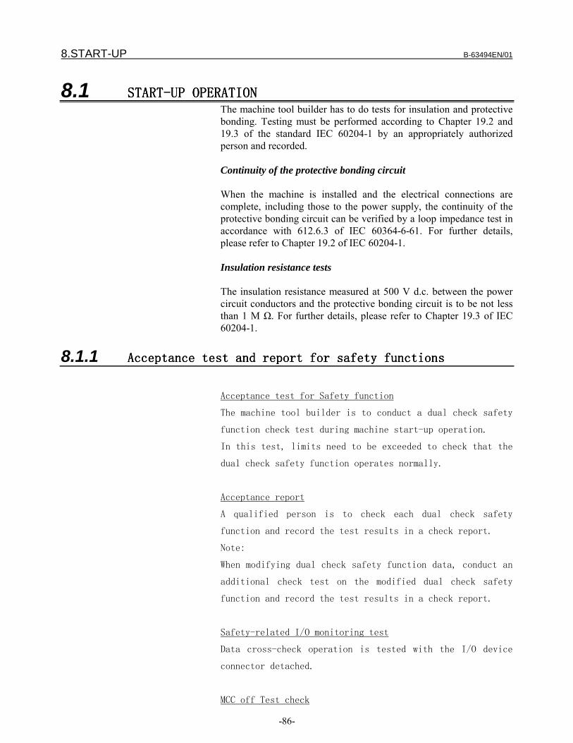
8.START-UP B-63494EN/01
-86-
8.1 START-UP START-UP START-UP START-UP OPERATIONOPERATIONOPERATIONOPERATIONThe machine tool builder has to do tests for insulation and protectivebonding. Testing must be performed according to Chapter 19.2 and19.3 of the standard IEC 60204-1 by an appropriately authorizedperson and recorded.
Continuity of the protective bonding circuit
When the machine is installed and the electrical connections arecomplete, including those to the power supply, the continuity of theprotective bonding circuit can be verified by a loop impedance test inaccordance with 612.6.3 of IEC 60364-6-61. For further details,please refer to Chapter 19.2 of IEC 60204-1.
Insulation resistance tests
The insulation resistance measured at 500 V d.c. between the powercircuit conductors and the protective bonding circuit is to be not lessthan 1 M Ω. For further details, please refer to Chapter 19.3 of IEC60204-1.
8.1.1 Acceptance test and report for safety functionsAcceptance test and report for safety functionsAcceptance test and report for safety functionsAcceptance test and report for safety functions
Acceptance test for Safety function
The machine tool builder is to conduct a dual check safety
function check test during machine start-up operation.
In this test, limits need to be exceeded to check that the
dual check safety function operates normally.
Acceptance report
A qualified person is to check each dual check safety
function and record the test results in a check report.
Note:
When modifying dual check safety function data, conduct an
additional check test on the modified dual check safety
function and record the test results in a check report.
Safety-related I/O monitoring test
Data cross-check operation is tested with the I/O device
connector detached.
MCC off Test check

B-63494EN/01 8.START-UP
-87-
The test mode signal is used to check that a MCC off Test
is conducted.
Negative test:
Conduct a MCC off Test by disconnecting the MCC contact
signal (input). Check that an alarm is issued and the MCC
remains to be shut off.
Safety limitation speed monitoring test
This test checks that when the actual speed exceeds a speed
limit, safety stop state is set by a stop response.
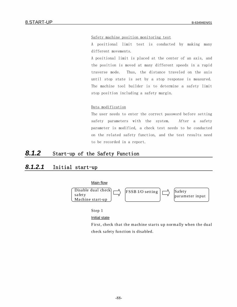
8.START-UP B-63494EN/01
-88-
Safety machine position monitoring test
A positional limit test is conducted by making many
different movements.
A positional limit is placed at the center of an axis, and
the position is moved at many different speeds in a rapid
traverse mode. Thus, the distance traveled on the axis
until stop state is set by a stop response is measured.
The machine tool builder is to determine a safety limit
stop position including a safety margin.
Data modification
The user needs to enter the correct password before setting
safety parameters with the system. After a safety
parameter is modified, a check test needs to be conducted
on the related safety function, and the test results need
to be recorded in a report.
8.1.2 Start-up of the Start-up of the Start-up of the Start-up of the SafetySafetySafetySafety FunctionFunctionFunctionFunction
8.1.2.1 Initial Initial Initial Initial start-upstart-upstart-upstart-up
Main flow
Step 1
Initial state
First, check that the machine starts up normally when the dual
check safety function is disabled.
Disable dual checksafetyMachine start-up
FSSB I/O setting Safetyparameter input
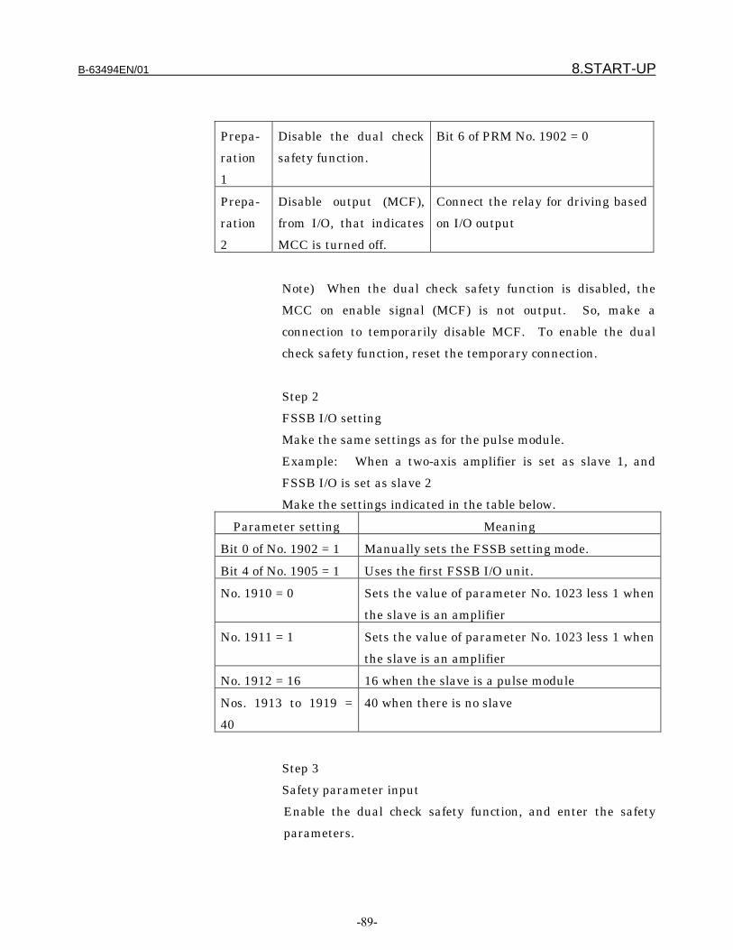
B-63494EN/01 8.START-UP
-89-
Prepa-
ration
1
Disable the dual check
safety function.
Bit 6 of PRM No. 1902 = 0
Prepa-
ration
2
Disable output (MCF),
from I/O, that indicates
MCC is turned off.
Connect the relay for driving based
on I/O output
Note) When the dual check safety function is disabled, the
MCC on enable signal (MCF) is not output. So, make a
connection to temporarily disable MCF. To enable the dual
check safety function, reset the temporary connection.
Step 2
FSSB I/O setting
Make the same settings as for the pulse module.
Example: When a two-axis amplifier is set as slave 1, and
FSSB I/O is set as slave 2
Make the settings indicated in the table below.
Parameter setting Meaning
Bit 0 of No. 1902 = 1 Manually sets the FSSB setting mode.
Bit 4 of No. 1905 = 1 Uses the first FSSB I/O unit.
No. 1910 = 0 Sets the value of parameter No. 1023 less 1 when
the slave is an amplifier
No. 1911 = 1 Sets the value of parameter No. 1023 less 1 when
the slave is an amplifier
No. 1912 = 16 16 when the slave is a pulse module
Nos. 1913 to 1919 =
40
40 when there is no slave
Step 3
Safety parameter input
Enable the dual check safety function, and enter the safety
parameters.

8.START-UP B-63494EN/01
-90-
Prepara-
tion 1
Enable the dual check safety
function.
Bit 6 of PRM No. 1902 = 1
Prepara-
tion 2
Enables output (MCF), from
I/O, that indicates MCC is
turned off.
Enable I/O output.
Set the safety parameters indicated in the table below.
Parameter setting Meaning
1942 Safety speed on each axis
1943 Safety position (+ direction) on each axis
1944 Safety position (- direction) on each axis
1945 Timer for safety input signal check
1946 Timer for MCC off Test
1947 Timer 1 for MCC off
1948 Timer 2 for MCC off
1838 Positional deviation limit value in mode C
2078 Dual position feedback conversion coefficient
(numerator)
2079 Dual position feedback conversion coefficient
(denominator)
4372 Safety speed on each spindle
Step 4
Execution of general machine tests
Axis and spindle optimization
Dual check safety function adjustment (safety limitation speed,
safety machine position)
Step 5
Test for checking the safety function
Check test execution and report creation
Step 6
Parameter preservation
Save all parameters including the safety parameters. The
parameters are used to start up the series.

B-63494EN/01 8.START-UP
-91-
Step 7
Set a password.
A password is used to disable unauthorized persons from
modifying safety parameters. Before safety parameters of the
equipment for which a password (No. 3225) is set can be
modified, the password value must be set as the keyword (No.
3226). Only those persons authorized to conduct a check test
should know the password value.
8.1.2.2 Series sSeries sSeries sSeries start-uptart-uptart-uptart-up
The parameters for the safety monitoring function are
transferred together with other parameters to the CNC as in
the case of normal series start-up. Perform a safety
function check test in addition to the normal start-up
procedure.
8.1.3 TroubleshootingTroubleshootingTroubleshootingTroubleshooting
Alarms related to the safety function are output on the
ALARM screen.
Correct the cause of trouble according to the chapter
describing alarms and messages in this manual. When a
component related to the safety function is to be replaced,
an authorized person must conduct a safety function check
test.

9.SAMPLE SYSTEM CONFIGURATION B-63494EN/01
-92-
SAMPLE SYSTEM CONFIGURATION
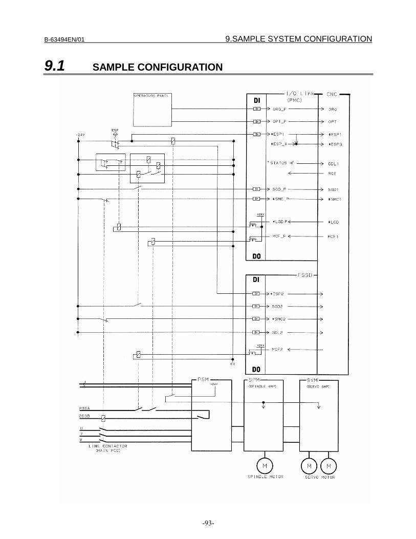
B-63494EN/01 9.SAMPLE SYSTEM CONFIGURATION
-93-
9.1 SAMPLE CONFIGURATION
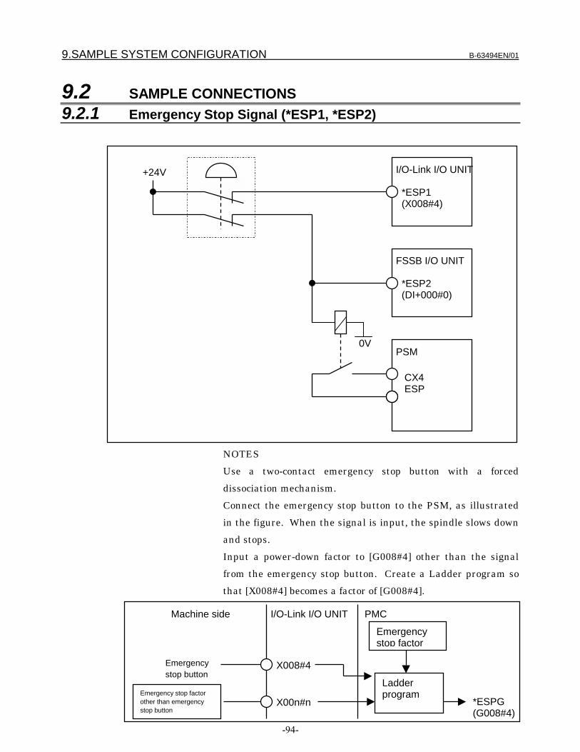
9.SAMPLE SYSTEM CONFIGURATION B-63494EN/01
-94-
9.2 SAMPLE CONNECTIONS9.2.1 Emergency Stop Signal (*ESP1, *ESP2)
NOTES
Use a two-contact emergency stop button with a forced
dissociation mechanism.
Connect the emergency stop button to the PSM, as illustrated
in the figure. When the signal is input, the spindle slows down
and stops.
Input a power-down factor to [G008#4] other than the signal
from the emergency stop button. Create a Ladder program so
that [X008#4] becomes a factor of [G008#4].
*ESP1(X008#4)
I/O-Link I/O UNIT
*ESP2(DI+000#0)
FSSB I/O UNIT
+24V
X00n#n
I/O-Link I/O UNIT PMC
LadderprogramEmergency stop factor
other than emergencystop button
Emergencystop factor
*ESPG(G008#4)
Machine side
X008#4Emergencystop button
CX4ESP
PSM0V

B-63494EN/01 9.SAMPLE SYSTEM CONFIGURATION
-95-
9.2.2 Guard Open Request Signal (ORQ)
NOTES
Create a Ladder program of conditions for making a guard open
request and then input the program to the PMC side [G191#3].
When the guard open request signal (ORQ) is input and when
CNC safety has been confirmed, the guard unlock enable signal
(*LGD) is output. If the CNC is not safe, ORQ input will not
result in output of *LGD.
If the input of ORQ is canceled while the guard is open, the
CNC enters a safely stopped status (state in which the guard is
open although the guard open request signal is not input).
Close the guard (SGD is set to 1), then cancel this signal.
9.2.3 Test Mode Signal (OPT)
X00n#n
I/O-Link I/O UNIT+24VGuard openrequest button PMC
Ladder program
ORQ(G191#3)
X00n#n
I/O-Link I/O UNIT+24VTest start button
PMC
Ladder program
OPT(G191#2)

9.SAMPLE SYSTEM CONFIGURATION B-63494EN/01
-96-
NOTES
Create a Ladder program for performing a MCC off Test, then
input the program to the PMC side [G191#2].

B-63494EN/01 9.SAMPLE SYSTEM CONFIGURATION
-97-
9.2.4 Guard Unlock Enable Signal (*LGD),Guard Lock State Signal (GDL), Guard State Signal (SGD)
+24V
SW1 SW2
SW3
0V
0V
X00n#nI/O Link I/O UNIT
SGD(DI+001#4)
FSSB I/O UNIT
Y00n#n
PMCSGD(G191#4)
*LGD(F191#0)
Ladderprogram
RY1
RY2
RY1
RY2
RY3
RY3RY3
RY1 RY2
Guard-monitoringlimit switch
Safety relay
[Sample control components]SW1/SW2:
Guard state monitoringswitch with forceddissociation mechanism
SW3:Guard lock switch
RY1, RY2, RY3:Safety relay
Guard closed
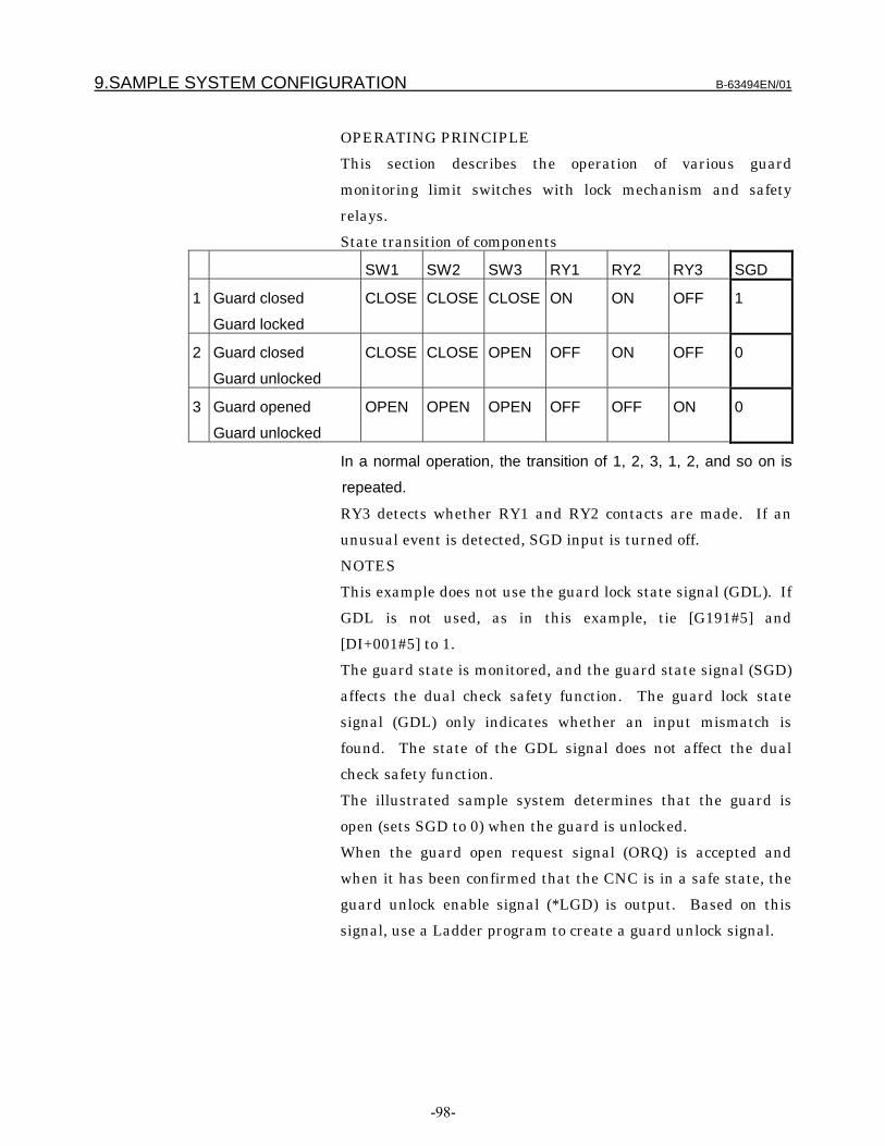
9.SAMPLE SYSTEM CONFIGURATION B-63494EN/01
-98-
OPERATING PRINCIPLE
This section describes the operation of various guard
monitoring limit switches with lock mechanism and safety
relays.
State transition of components
SW1 SW2 SW3 RY1 RY2 RY3 SGD
1 Guard closed
Guard locked
CLOSE CLOSE CLOSE ON ON OFF 1
2 Guard closed
Guard unlocked
CLOSE CLOSE OPEN OFF ON OFF 0
3 Guard opened
Guard unlocked
OPEN OPEN OPEN OFF OFF ON 0
In a normal operation, the transition of 1, 2, 3, 1, 2, and so on is
repeated.
RY3 detects whether RY1 and RY2 contacts are made. If an
unusual event is detected, SGD input is turned off.
NOTES
This example does not use the guard lock state signal (GDL). If
GDL is not used, as in this example, tie [G191#5] and
[DI+001#5] to 1.
The guard state is monitored, and the guard state signal (SGD)
affects the dual check safety function. The guard lock state
signal (GDL) only indicates whether an input mismatch is
found. The state of the GDL signal does not affect the dual
check safety function.
The illustrated sample system determines that the guard is
open (sets SGD to 0) when the guard is unlocked.
When the guard open request signal (ORQ) is accepted and
when it has been confirmed that the CNC is in a safe state, the
guard unlock enable signal (*LGD) is output. Based on this
signal, use a Ladder program to create a guard unlock signal.
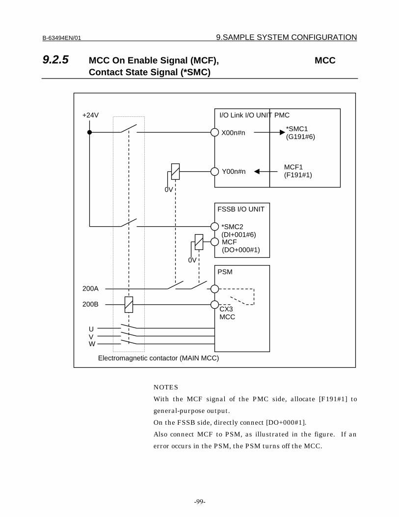
B-63494EN/01 9.SAMPLE SYSTEM CONFIGURATION
-99-
9.2.5 MCC On Enable Signal (MCF), MCCContact State Signal (*SMC)
NOTES
With the MCF signal of the PMC side, allocate [F191#1] to
general-purpose output.
On the FSSB side, directly connect [DO+000#1].
Also connect MCF to PSM, as illustrated in the figure. If an
error occurs in the PSM, the PSM turns off the MCC.
X00n#n
I/O Link I/O UNIT
FSSB I/O UNIT
Y00n#n
PMC
MCF1(F191#1)
*SMC2(DI+001#6)MCF(DO+000#1)
0V
PSM
+24V
200A
200B
UVW
0V
Electromagnetic contactor (MAIN MCC)
CX3MCC
*SMC1(G191#6)
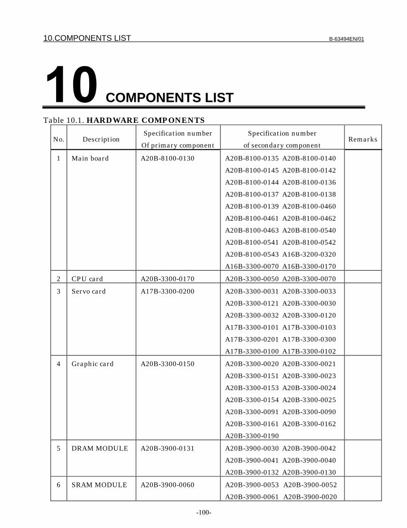
10.COMPONENTS LIST B-63494EN/01
-100-
COMPONENTS LISTTable 10.1. HARDWARE COMPONENTS
No. DescriptionSpecification number
Of primary component
Specification number
of secondary componentRemarks
1 Main board A20B-8100-0130 A20B-8100-0135
A20B-8100-0145
A20B-8100-0144
A20B-8100-0137
A20B-8100-0139
A20B-8100-0461
A20B-8100-0463
A20B-8100-0541
A20B-8100-0543
A16B-3300-0070
A20B-8100-0140
A20B-8100-0142
A20B-8100-0136
A20B-8100-0138
A20B-8100-0460
A20B-8100-0462
A20B-8100-0540
A20B-8100-0542
A16B-3200-0320
A16B-3300-0170
2 CPU card A20B-3300-0170 A20B-3300-0050 A20B-3300-0070
3 Servo card A17B-3300-0200 A20B-3300-0031
A20B-3300-0121
A20B-3300-0032
A17B-3300-0101
A17B-3300-0201
A17B-3300-0100
A20B-3300-0033
A20B-3300-0030
A20B-3300-0120
A17B-3300-0103
A17B-3300-0300
A17B-3300-0102
4 Graphic card A20B-3300-0150 A20B-3300-0020
A20B-3300-0151
A20B-3300-0153
A20B-3300-0154
A20B-3300-0091
A20B-3300-0161
A20B-3300-0190
A20B-3300-0021
A20B-3300-0023
A20B-3300-0024
A20B-3300-0025
A20B-3300-0090
A20B-3300-0162
5 DRAM MODULE A20B-3900-0131 A20B-3900-0030
A20B-3900-0041
A20B-3900-0132
A20B-3900-0042
A20B-3900-0040
A20B-3900-0130
6 SRAM MODULE A20B-3900-0060 A20B-3900-0053
A20B-3900-0061
A20B-3900-0052
A20B-3900-0020

B-63494EN/01 10.COMPONENTS LIST
-101-
7 FROM MODULE A20B-3900-0011 A20B-3900-0014
A20B-3900-0013
A20B-3900-0012
A20B-3900-0071
A20B-3900-0070
A20B-3900-0074
A20B-3900-0073
A20B-3900-0072
A20B-3900-0010
8 FSSB
ADDITIONAL
DETECTOR
INTERFACE
A20B-2100-0270
9 I/O module A20B-2100-0150
A20B-2100-0410
A20B-2100-0411
A20B-2002-0470
A20B-2002-0521
A20B-2002-0400
A20B-2002-0401
A20B-2100-0320
A20B-2002-0520
10 I/O Unit base
module
A20B-9001-0020 A20B-9001-0040
A20B-2000-0510
A20B-2000-0550
11 I/O Unit interface
module
A20B-8000-0410 A20B-8000-0420
A20B-8000-0820
A20B-8000-0710
12 DC digital input
module
A20B-9000-0901
A20B-9000-0902
A20B-9000-0970
A20B-9001-0011
A20B-9001-0281
A20B-9000-0972
A20B-9001-0490
A20B-9000-0971
A20B-9001-0010
A20B-8000-0341
A20B-9001-0280
A20B-8000-0510
13 DC digital output
module
A20B-9000-0921 A20B-9001-0220
A20B-8000-0440
A20B-9001-0490
A20B-8000-0741
A20B-9001-0681
A20B-8000-0780
A20B-8002-0070
A20B-8000-0510
A20B-8000-0740
A20B-9001-0680
A20B-8000-0760
14 DC digital
input/output
module
A20B-8000-0750
A20B-8000-0730
A20B-8000-0751
A20B-8000-0731
15 AC digital input
module
A20B-8000-0341 A20B-9001-0940
16 AC digital output
module
A20B-8000-0470
A20B-8000-0321
A20B-8000-0480
A20B-8000-0880
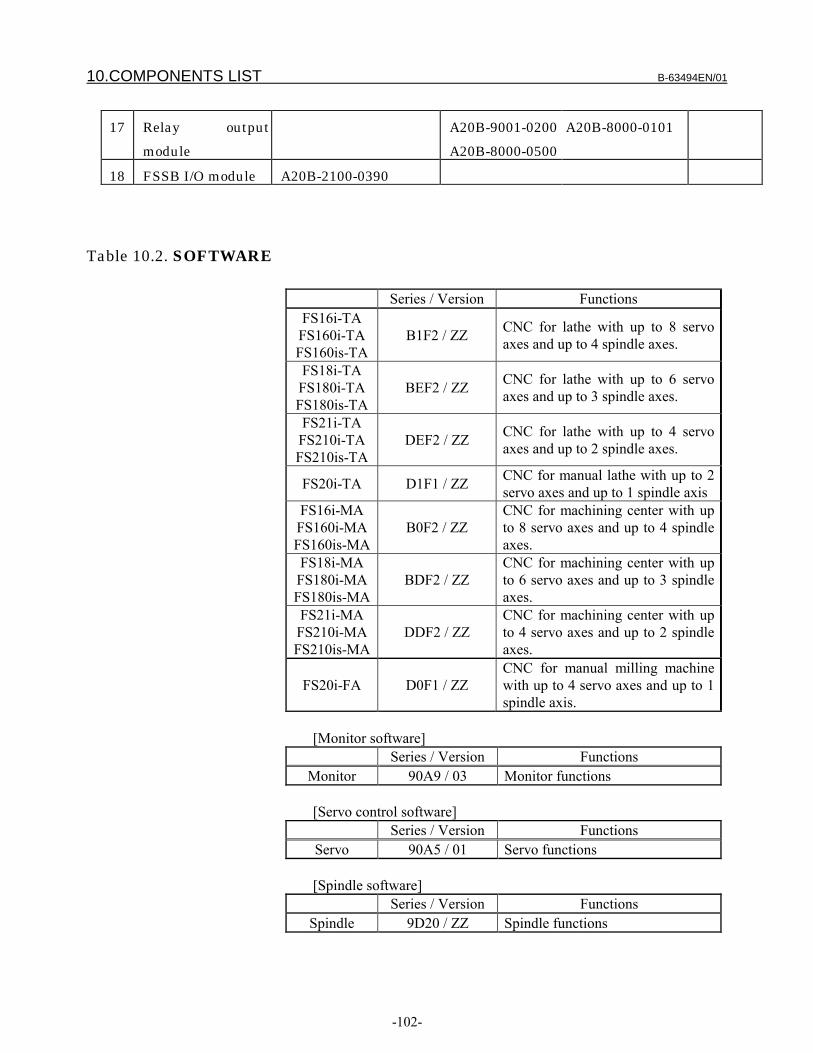
10.COMPONENTS LIST B-63494EN/01
-102-
17 Relay output
module
A20B-9001-0200
A20B-8000-0500
A20B-8000-0101
18 FSSB I/O module A20B-2100-0390
Table 10.2. SOFTWARE
Series / Version FunctionsFS16i-TAFS160i-TAFS160is-TA
B1F2 / ZZ CNC for lathe with up to 8 servoaxes and up to 4 spindle axes.
FS18i-TAFS180i-TAFS180is-TA
BEF2 / ZZ CNC for lathe with up to 6 servoaxes and up to 3 spindle axes.
FS21i-TAFS210i-TAFS210is-TA
DEF2 / ZZ CNC for lathe with up to 4 servoaxes and up to 2 spindle axes.
FS20i-TA D1F1 / ZZ CNC for manual lathe with up to 2servo axes and up to 1 spindle axis
FS16i-MAFS160i-MAFS160is-MA
B0F2 / ZZCNC for machining center with upto 8 servo axes and up to 4 spindleaxes.
FS18i-MAFS180i-MAFS180is-MA
BDF2 / ZZCNC for machining center with upto 6 servo axes and up to 3 spindleaxes.
FS21i-MAFS210i-MAFS210is-MA
DDF2 / ZZCNC for machining center with upto 4 servo axes and up to 2 spindleaxes.
FS20i-FA D0F1 / ZZCNC for manual milling machinewith up to 4 servo axes and up to 1spindle axis.
[Monitor software]Series / Version Functions
Monitor 90A9 / 03 Monitor functions
[Servo control software]Series / Version Functions
Servo 90A5 / 01 Servo functions
[Spindle software]Series / Version Functions
Spindle 9D20 / ZZ Spindle functions

EDITSHEET
DRAW. NO. CUST
TITLE
DESCRIPTIONDESIGDATE /091
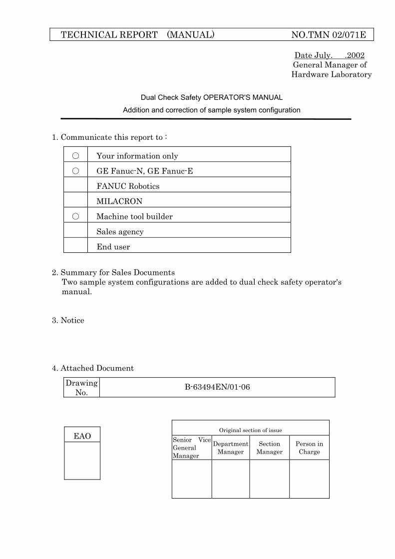
TECHNICAL REPORT (MANUAL) NO.TMN 02/071E
Date July. .2002 General Manager of Hardware Laboratory
Dual Check Safety OPERATOR'S MANUAL
Addition and correction of sample system configuration
1. Communicate this report to :
Your information only
GE Fanuc-N, GE Fanuc-E
FANUC Robotics
MILACRON
Machine tool builder
Sales agency
End user
2. Summary for Sales Documents Two sample system configurations are added to dual check safety operator's manual.
3. Notice 4. Attached Document
Drawing No. B-63494EN/01-06
EAO
Original section of issue Senior Vice General Manager
Department Manager
Section Manager
Person in Charge
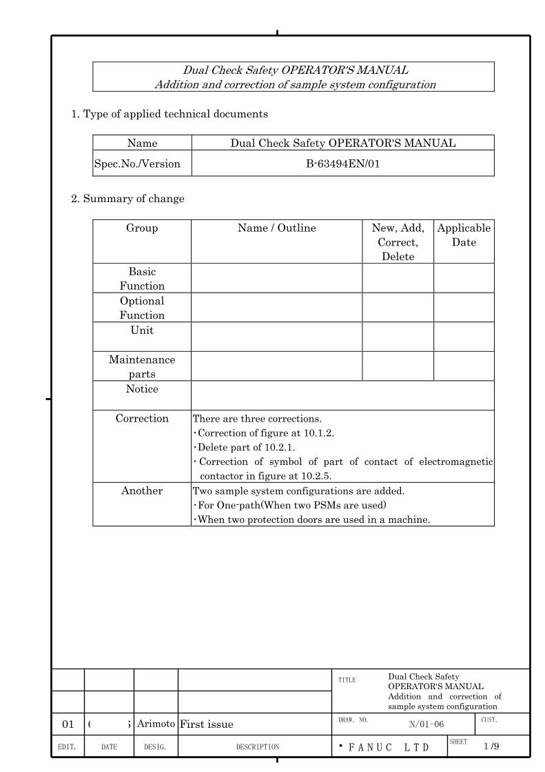
02.06.26 Arimoto First issue
B-63494EN/01-06
Dual Check Safety OPERATOR'S MANUAL Addition and correction of sample system configuration
1. Type of applied technical documents
Name Dual Check Safety OPERATOR'S MANUAL
Spec.No./Version B-63494EN/01
2. Summary of change
Group Name / Outline New, Add, Correct, Delete
Applicable Date
Basic Function
Optional Function
Unit
Maintenance parts
Notice
Correction
There are three corrections. ・Correction of figure at 10.1.2. ・Delete part of 10.2.1. ・Correction of symbol of part of contact of electromagnetic
contactor in figure at 10.2.5. Another
Two sample system configurations are added. ・For One-path(When two PSMs are used) ・When two protection doors are used in a machine.
EDIT. F A N U C L T DSHEET
DRAW. NO. CUST.
TITLE
1/9DESCRIPTIONDESIG.DATE
Dual Check Safety OPERATOR'S MANUAL Addition and correction ofsample system configuration
01

Change a title of 10.1.1 as follows
10.1.1 For One-path(When one PSM is used)
EDIT. F A N U C L T DSHEET
DRAW. NO. CUST.
TITLE
2/9DESCRIPTIONDESIG.DATE
B-63494EN/01-06

Cange 10.1.2 to 10.1.3 and change figure as follows
10.1.3 For Two-path(When the main side and sub side use a common MCC)
EDIT. F A N U C L T DSHEET
DRAW. NO. CUST.
TITLE
3/9DESCRIPTIONDESIG.DATE
B-63494EN/01-06
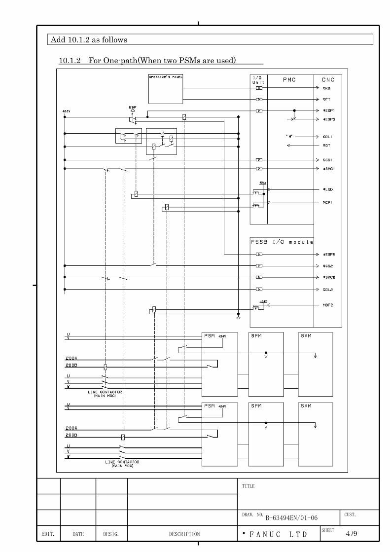
Add 10.1.2 as follows
10.1.2 For One-path(When two PSMs are used)
EDIT. F A N U C L T DSHEET
DRAW. NO. CUST.
TITLE
4/9DESCRIPTIONDESIG.DATE
B-63494EN/01-06

Change 10.1.3 to 10.1.4 Delete statement shown below and figure of 10.2.1.
Input a power-down factor to [G008#4] other than the signal from the emergency stop button. Create a Ladder program so that [X008#4] becomes a factor of [G008#4].
Add statement shown below between a title of 10.2.4 and figure.
When one protection door is used Example combined a guard-monitoring limit switch with lock mechanism and a safety relay in case of one protection door is shown below.
EDIT. F A N U C L T DSHEET
DRAW. NO. CUST.
TITLE
5/9DESCRIPTIONDESIG.DATE
B-63494EN/01-06
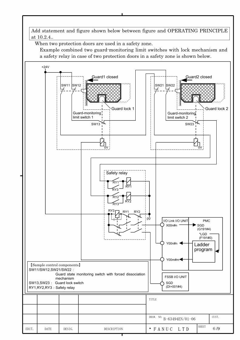
EDIT. F A N
DRAW. NO.
TITLE
DESCRIPTIONDESIG.DATE
Add statement and figure shown below between figure and OPERATING PRINCIPLE at 10.2.4..
When two protection doors are used in a safety zone. Example combined two guard-monitoring limit switches with lock mechanism and a safety relay in case of two protection doors in a safety zone is shown below.
+24V
SW11
X00n#n I/O Link I/O UNIT
Y00n#n
PMC
*LGD (F191#0)
Ladder program
Safety relay
【Sample control components】 SW11/SW12,SW21/SW22:
Guard state monitoring switch with forced dissociationmechanism
SW13,SW23: Guard lock switch RY1,RY2,RY3:Safety relay
Guard1 closed Guard2 closed
Guard lock 1
0V
SW23
SW22 SW21
SW13
SW12
Y00m#m
RY3
0V
RY3
RY3
RY2
RY2 RY2
RY1
RY1 RY1
0V
FSSB I/O UNIT
U C L T D
B-63494EN/01-06
SGD (DI+001#4)
SGD (G191#4)
Guard-monitoringlimit switch 1
Guard-monitoringlimit switch 2
SHE
Guard lock 2
ET
CUST.
6/9

Change OPERATING PRINCIPLE at 10.2.4 as follows
OPERATING PRINCIPLE When one protection door is used
State of components is shown below.
State of components Guard Guard lock SW1 SW2 SW3 RY1 RY2 RY3 SGD 1 CLOSE LOCK CLOSE CLOSE CLOSE ON ON OFF 1 2 CLOSE UNLOCK CLOSE CLOSE OPEN OFF ON OFF 0 3 OPEN UNLOCK OPEN OPEN OPEN OFF OFF ON 0
In case of no welding of contact in safety relay when state of protection door is changed to open from close and close, transition of 1,2,3,2,1 is occured. RY3 detects whether RY1 and RY2 contacts are made. If an unusual event is detected, SGD input is turned off.
When two protection doors are used in a safety zone This example has construction added a guard-monitoring limit switch to example of "When one protection door is used". Two guard state monitoring switches of two guard-monitoring limit switches are connected series. When at least one guard is open SGD is turned off and the system determines that the guard is open. Two signals are outputed from I/O Link I/O UNIT to open each guard lock switch individually. When at least one guard lock is released by these signals SGD input is turned off and the system determines that the guard is open. State of components is shown below.
State of components Guard1 Guard lock1 Guard2 Guard lock
2
SW1 SW12 SW13 SW21 SW22 SW23 RY1 RY2 RY3 SGD
1 CLOSE LOCK CLOSE LOCK CLOSE CLOSE CLOSE CLOSE CLOSE CLOSE ON ON OFF 1
2 CLOSE UNLOCK CLOSE LOCK CLOSE CLOSE OPE
N
CLOSE CLOSE CLOSE OF
F
ON OFF 0
3 OPE
N
UNLOCK CLOSE LOCK OPE
N
OPE
N
OPE
N
CLOSE CLOSE CLOSE OF
F
OF
F
ON 0
4 CLOSE LOCK CLOSE UNLOCK CLOSE CLOSE CLOSE CLOSE CLOSE OPE
N
OF
F
ON OFF 0
5 CLOSE UNLOCK CLOSE UNLOCK CLOSE CLOSE OPE
N
CLOSE CLOSE OPE
N
OF
F
ON OFF 0
6 OPE
N
UNLOCK CLOSE UNLOCK OPE
N
OPE
N
OPE
N
CLOSE CLOSE OPE
N
OF
F
OF
F
ON 0
EDIT. F A N U C L T DSHEET
DRAW. NO. CUST.
TITLE
7/9DESCRIPTIONDESIG.DATE
B-63494EN/01-06

7 CLOSE LOCK OPE
N
UNLOCK CLOSE CLOSE CLOSE OPE
N
OPE
N
OPE
N
OF
F
OF
F
ON 0
8 CLOSE UNLOCK OPE
N
UNLOCK CLOSE CLOSE OPE
N
OPE
N
OPE
N
OPE
N
OF
F
OF
F
ON 0
9 OPE
N
UNLOCK OPE
N
UNLOCK OPE
N
OPE
N
OPE
N
OPE
N
OPE
N
OPE
N
OF
F
OF
F
ON 0
EDIT. F A N U C L T DSHEET
DRAW. NO. CUST.
TITLE
8/9DESCRIPTIONDESIG.DATE
B-63494EN/01-06

In case of no welding of contact in safety relay when guard2 is open and close with keeping guard1 close transition of 1,4,7,4,1 is occured. RY3 detects whether RY1 and RY2 contacts are made like "When one protection door is used". If an unusual event is detected, SGD input is turned off.
Change NOTES at 10.2.4 as follows
NOTE This example does not use the guard lock state signal (GDL). If GDL is not used, as in this example, tie [G191#5] and [DI+001#5] to 1. The guard state is monitored, and the guard state signal (SGD) affects the dual check safety function. The guard lock state signal (GDL) only indicates whether an input mismatch is found. The state of the GDL signal does not affect the dual check safety function. In case of that one protection door is used the illustrated sample system determines that the guard is open (sets SGD to 0) when the guard is unlocked. In case of that two protection doors are used in a safety zone the illustrated sample system determines that the guard is open (sets SGD to 0) when at least one guard is unlocked. When the guard open request signal (ORQ) is accepted and when it has been confirmed that the CNC is in a safe state, the guard unlock signal (*LGD) is output. Based on this signal, use a Ladder program to create a guard unlock signal.
EDIT. F A N U C L T DSHEET
DRAW. NO. CUST.
TITLE
9/9DESCRIPTIONDESIG.DATE
B-63494EN/01-06

Change figure at 10.2.5 as follows(A symbol of a part of contact of electromagnetic contactor is changed.)
*SMC1 (G191#6)
CX3MCC
Electromagnetic contactor (MAIN MCC)
0V
U V W
200B
200A
+24V
PSM
0V
MCF2 (DO+000#1)
*SMC2 (DI+001#6)
MCF1 (F191#1)
PMC
Y00n#n
FSSB I/O UNIT
I/O Link I/O UNIT
X00n#n
EDIT. F A N U C L T DSHEET
DRAW. NO. CUST.
TITLE
10/9DESCRIPTIONDESIG.DATE
B-63494EN/01-06
Ed.
Page
Nam
e N
o.
Date ContentsDraw up
FS16i/18i/21i-TB/MB, FS18i-MB5 Programmable Safe-related I/O signals
A-78882E
1/14 Jul.19, 2002
02 Nov. 7, 2002 O.Abe corrected at [1]
04 Nov. 20, 2003 T.Inagaki corrected at [3] 03 Nov. 11, 2002 O.Abe corrected at [2] and corrected Fig. 1
Contents
1.1 OUTLINE ...................................................................................................................................................... 2
1.2 SPECIFICATIONS........................................................................................................................................ 4
1.3 SIGNALS...................................................................................................................................................... 6
1.4 PARAMETERS............................................................................................................................................. 8
1.5 C-LANGUAGE EXECUTOR ........................................................................................................................ 9
1.6 ALARMS AND MESSAGES ...................................................................................................................... 14
FANUC Series 16i/18i/21i–TB/MB
FANUC Series 18i-MB5
Dual Check Safety Programmable Safe-related I/O signals
Specifications

Ed.
Page
Nam
e N
o.
Date ContentsDraw up
FS16i/18i/21i-TB/MB, FS18i-MB5 Programmable Safe-related I/O signals
A-78882E
2/14 Jul.19, 2002
02 Nov. 7, 2002 O.Abe corrected at [1]
04 Nov. 20, 2003 T.Inagaki corrected at [3] 03 Nov. 11, 2002 O.Abe corrected at [2] and corrected Fig. 1
1.1 Outline In the Dual Check Safety function, “Safe-related I/O signal monitoring function” has been developed for the machine having only one safety guard. This time, FANUC has added the new specifications to “Safe-related I/O signal monitoring function” as “Programmable Safe-related I/O signals”. These features are as follows. (1) Each path can have 16 points of DI signals which are cross-checked by both
CNC CPU and Monitor CPU as Programmable Safe-related I/O signals. (2) Logic that handles those signals can be developed by machine tool builder
using C-language executor and PMC ladder function. (3) As output of above mentioned logic, each path can have 8 points of DO
signals which are cross-checked by both CNC CPU and Monitor CPU as Programmable Safe related I/O signals.
note) The 2nd path of 1 CPU 2 path control and the 3rd path of 2 CPU 3 path
control have no free DI/DO signals because they have no FSSB I/O module. This function will be helpful to apply to the machine having 2 safety guards and flexible machine inputs logic. The C-language executor is required to use this function. This function is inapplicable to loader control. “Safe-related I/O signal monitoring function” executed by the former method is applied to loader control. The following software are required for this improvement:
FS16i-TB B1H1-22 or later FS18i-TB BEH1-22 or later FS21i-TB DEH1-22 or later FS16i-MB B0H1-22 or later FS18i-MB BDH1-22 or later FS18i-MB5 BDH5-12 or later FS21i-MB DDH1-22 or later Monitor 90B9-03 Servo 90B0-20 or later 90B3-04 or later 90B7-04 or later C-language executor library BY01-2.9F or later
[1]
[3]
[3]

Ed.
Page
Nam
e N
o.
Date ContentsDraw up
FS16i/18i/21i-TB/MB, FS18i-MB5 Programmable Safe-related I/O signals
A-78882E
3/14 Jul.19, 2002
02 Nov. 7, 2002 O.Abe corrected at [1]
04 Nov. 20, 2003 T.Inagaki corrected at [3] 03 Nov. 11, 2002 O.Abe corrected at [2] and corrected Fig. 1
NOTE This function will be under investigation at TUV soon. So these required software versions are subject to change without notice.
[1]

Ed.
Page
Nam
e N
o.
Date ContentsDraw up
FS16i/18i/21i-TB/MB, FS18i-MB5 Programmable Safe-related I/O signals
A-78882E
4/14 Jul.19, 2002
02 Nov. 7, 2002 O.Abe corrected at [1]
04 Nov. 20, 2003 T.Inagaki corrected at [3] 03 Nov. 11, 2002 O.Abe corrected at [2] and corrected Fig. 1
1.2 Specifications
CNC C-language executor
Monitor
PMC
I/O Link #1 FSSB I/O #2
*ESP, *SMC, GDL,
SGD, Free 16 points
MCF, Free 8 points
LGD
ORQ, OPT
User Logic
Speed/ Position
Monitoring and so on DO
Cross- check
DICross- check
User Logic
Speed/ Position
Monitoring and so on
X signals
G191G334G335G331
F191
Y signals DI+000~DI+003
DO+000DO+001
Free 8 points MCF
MCF,LGD
Free 8
Fig 1. Concept of function
[a]
[b]
[c]
[d] [e]
[f]
[g]
[i]
[k]
Note) The mark [a]~[m] are for reference to“Sequence of ProgrammableSafe-related I/O signals Function”mentioned in the following page.
[l]
[e] [m]
[h][j]
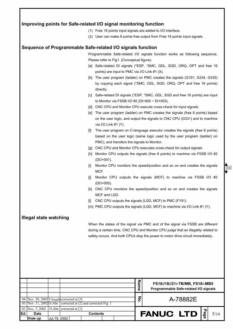
Ed.
Page
Nam
e N
o.
Date ContentsDraw up
FS16i/18i/21i-TB/MB, FS18i-MB5 Programmable Safe-related I/O signals
A-78882E
5/14 Jul.19, 2002
02 Nov. 7, 2002 O.Abe corrected at [1]
04 Nov. 20, 2003 T.Inagaki corrected at [3] 03 Nov. 11, 2002 O.Abe corrected at [2] and corrected Fig. 1
Improving points for Safe-related I/O signal monitoring function (1) Free 16 points input signals are added to I/O interface. (2) User can make 8 points free output from Free 16 points input signals.
Sequence of Programmable Safe-related I/O signals function
Programmable Safe-related I/O signals function works as following sequence. Please refer to Fig1. (Conceptual figure). [a] Safe-related DI signals (*ESP, *SMC, GDL, SGD, ORQ, OPT and free 16
points) are input to PMC via I/O Link #1 (X). [b] The user program (ladder) on PMC creates the signals (G191, G334, G335)
by copying each signal (*SMC, GDL, SGD, ORQ, OPT and free 16 points) directly.
[c] Safe-related DI signals (*ESP, *SMC, GDL, SGD and free 16 points) are input to Monitor via FSSB I/O #2 (DI+000 ~ DI+003).
[d] CNC CPU and Monitor CPU execute cross-check for input signals. [e] The user program (ladder) on PMC creates the signals (free 8 points) based
on the user logic, and output the signals to CNC CPU (G331) and to machine via I/O Link #1 (Y).
[f] The user program on C-language executor creates the signals (free 8 points) based on the user logic (same logic used by the user program (ladder) on PMC), and transfers the signals to Monitor.
[g] CNC CPU and Monitor CPU executes cross-check for output signals. [h] Monitor CPU outputs the signals (free 8 points) to machine via FSSB I/O #2
(DO+001). [i] Monitor CPU monitors the speed/position and so on and creates the signals
MCF. [j] Monitor CPU outputs the signals (MCF) to machine via FSSB I/O #2
(DO+000). [k] CNC CPU monitors the speed/position and so on and creates the signals
MCF and LGD. [l] CNC CPU outputs the signals (LGD, MCF) to PMC (F191). [m] PMC CPU outputs the signals (LGD, MCF) to machine via I/O Link #1 (Y).
Illegal state watching When the states of the signal via PMC and of the signal via FSSB are different during a certain time, CNC CPU and Monitor CPU judge that an illegality related to safety occurs. And both CPUs stop the power to motor drive circuit immediately.
[2]

Ed.
Page
Nam
e N
o.
Date ContentsDraw up
FS16i/18i/21i-TB/MB, FS18i-MB5 Programmable Safe-related I/O signals
A-78882E
6/14 Jul.19, 2002
02 Nov. 7, 2002 O.Abe corrected at [1]
04 Nov. 20, 2003 T.Inagaki corrected at [3] 03 Nov. 11, 2002 O.Abe corrected at [2] and corrected Fig. 1
1.3 Signals 1.3.1 Signals Programable safe-related DI signal SDI00~SDI15 <G334, G335> <DI+002, DI+003>
[Classification] Input signal [Function] CNC and Monitor use these signals only for cross-check for input signals in Dual
Check Safety. [Operation] These signals are able to be used freely by user.
WARNING ・ The 2nd path of 1 CPU 2 path control and the 3rd path of 2 CPU 3 path
control have no Programmable safe-related DI signals because they have no FSSB I/O module.
Programmable safe-related DO signal SDO00~SDO07 <G331> <DO+001>
[Classification] Input signal [Function] CNC and Monitor use these signals only for cross-check for output signals in Dual
Check Safety. [Operation] These signals are able to be used freely by user.
WARNING ・ ‘DO’ used in these signals name means output signals from the user
program, but not from CNC. So these signals is addressed in ‘G’ signals.
・ The 2nd path of 1 CPU 2 path control and the 3rd path of 2 CPU 3 path control have no Programmable safe-related DO signals because they have no FSSB I/O module.
[2]
[2]

Ed.
Page
Nam
e N
o.
Date ContentsDraw up
FS16i/18i/21i-TB/MB, FS18i-MB5 Programmable Safe-related I/O signals
A-78882E
7/14 Jul.19, 2002
02 Nov. 7, 2002 O.Abe corrected at [1]
04 Nov. 20, 2003 T.Inagaki corrected at [3] 03 Nov. 11, 2002 O.Abe corrected at [2] and corrected Fig. 1
1.3.2 Signal addresses via PMC
#7 #6 #5 #4 #3 #2 #1 #0
X008 *ESP1
G008 *ESPG
G191 *SMC1 GDL1 SGD1 ORQ OPT
G331 SDO07 SDO06 SDO05 SDO04 SDO03 SDO02 SDO01 SDO00
G334 SDI07 SDI06 SDI05 SDI04 SDI03 SDI02 SDI01 SDI00
G335 SDI15 SDI14 SDI13 SDI12 SDI11 SDI10 SDI09 SDI08
#7 #6 #5 #4 #3 #2 #1 #0
F191 RQT MCF1 LGD
via FSSB
#7 #6 #5 #4 #3 #2 #1 #0
DI+000 *ESP2
DI+001 *SMC2 GDL2 SGD2
DI+002 SDI07 SDI06 SDI05 SDI04 SDI03 SDI02 SDI01 SDI00
DI+003 SDI15 SDI14 SDI13 SDI12 SDI11 SDI10 SDI09 SDI08
#7 #6 #5 #4 #3 #2 #1 #0
DO+000 MCF2
DO+001 SDO07 SDO06 SDO05 SDO04 SDO03 SDO02 SDO01 SDO00
WARNING ・ The 2nd path of 1 CPU 2 path control and the 3rd path of 2 CPU 3 path
control have no Safe programmable DI/DO signals because they have no FSSB I/O module.

Ed.
Page
Nam
e N
o.
Date ContentsDraw up
FS16i/18i/21i-TB/MB, FS18i-MB5 Programmable Safe-related I/O signals
A-78882E
8/14 Jul.19, 2002
02 Nov. 7, 2002 O.Abe corrected at [1]
04 Nov. 20, 2003 T.Inagaki corrected at [3] 03 Nov. 11, 2002 O.Abe corrected at [2] and corrected Fig. 1
1.4 Parameters
#7 #6 #5 #4 #3 #2 #1 #0 13800 CIO
[Data type] Bit CIO Programmable safe-related I/O signals are
0: Disabled. 1: Enabled.
CAUTION When this parameter is set, power must be turned off before
operation is continued. This parameter is protected by key and password of Dual Check
Safety. If those parameters should be changed, please set the password for safe parameters to the key for safe parameters (parameter No.3226).
In the multi-path system, this parameter is specified for each path. This parameter is disabled on the 2nd path of 1 CPU 2 path control,
the 3rd path of 2 CPU 3 path control and the loader control.
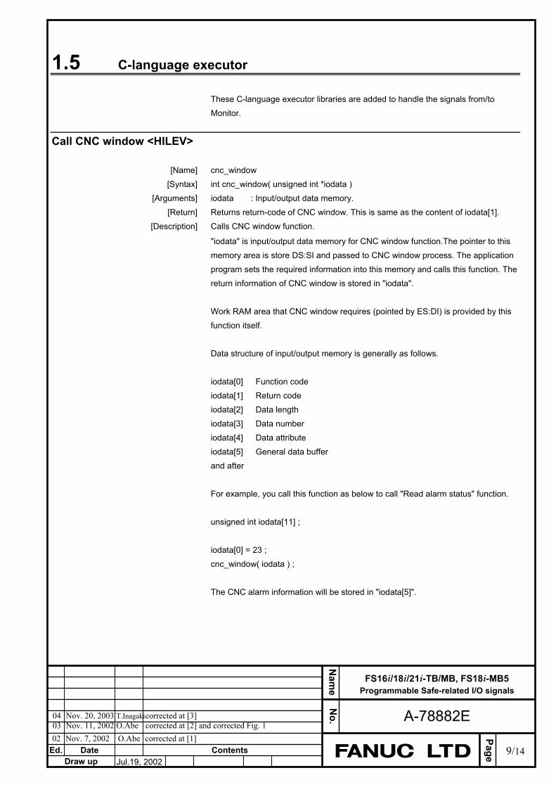
Ed.
Page
Nam
e N
o.
Date ContentsDraw up
FS16i/18i/21i-TB/MB, FS18i-MB5 Programmable Safe-related I/O signals
A-78882E
9/14 Jul.19, 2002
02 Nov. 7, 2002 O.Abe corrected at [1]
04 Nov. 20, 2003 T.Inagaki corrected at [3] 03 Nov. 11, 2002 O.Abe corrected at [2] and corrected Fig. 1
1.5 C-language executor These C-language executor libraries are added to handle the signals from/to Monitor.
Call CNC window <HILEV>
[Name] cnc_window [Syntax] int cnc_window( unsigned int *iodata ) [Arguments] iodata : Input/output data memory. [Return] Returns return-code of CNC window. This is same as the content of iodata[1]. [Description] Calls CNC window function.
"iodata" is input/output data memory for CNC window function.The pointer to this memory area is store DS:SI and passed to CNC window process. The application program sets the required information into this memory and calls this function. The return information of CNC window is stored in "iodata". Work RAM area that CNC window requires (pointed by ES:DI) is provided by this function itself. Data structure of input/output memory is generally as follows. iodata[0] Function code iodata[1] Return code iodata[2] Data length iodata[3] Data number iodata[4] Data attribute iodata[5] General data buffer and after For example, you call this function as below to call "Read alarm status" function. unsigned int iodata[11] ; iodata[0] = 23 ; cnc_window( iodata ) ; The CNC alarm information will be stored in "iodata[5]".

Ed.
Page
Nam
e N
o.
Date ContentsDraw up
FS16i/18i/21i-TB/MB, FS18i-MB5 Programmable Safe-related I/O signals
A-78882E
10/14Jul.19, 2002
02 Nov. 7, 2002 O.Abe corrected at [1]
04 Nov. 20, 2003 T.Inagaki corrected at [3] 03 Nov. 11, 2002 O.Abe corrected at [2] and corrected Fig. 1
High-Level application program can not call all CNC window functions. Only following functions are available.
(1)Read program number in executing. (2) Read sequence number in executing. (3) Read actual feed rate of controlled axes. (4) Read actual spindle speed. (5) Read absolute position. (6) Read machine position. (7) Read relative position. (8) Read distance to go. (9) Read skipped position. (10) Read servo delay amount. (11) Read acceleration/deceleration delay amount. (12) Read alarm status. (13) Read abnormal load torque data. (14) Read load information of serial spindle. (15) Read A/D conversion data. (Read load data of servo axis) (16) Read Programable Safe-related DI Signal. (17) Write Programable Safe-related DO Signal.
The detail descriptions of each functions will be offered later. This function takes approx. 0.03 msec at least for calling CNC window (in case of FS16i/18i). The execution time may exceed the max. execution time (1 msec) by calling this function so many times because of increasing processing time. Therefore, you should use this function up to 10 times at maximum for each 8 msec processing.
[2] [2]
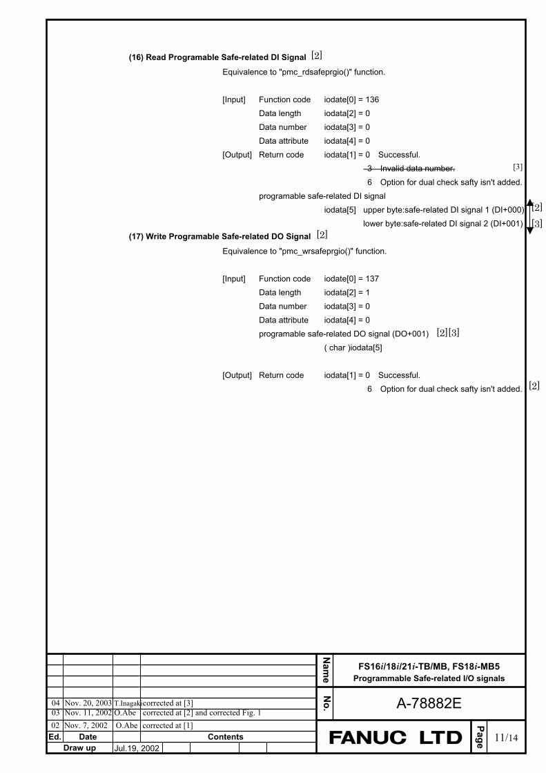
Ed.
Page
Nam
e N
o.
Date ContentsDraw up
FS16i/18i/21i-TB/MB, FS18i-MB5 Programmable Safe-related I/O signals
A-78882E
11/14Jul.19, 2002
02 Nov. 7, 2002 O.Abe corrected at [1]
04 Nov. 20, 2003 T.Inagaki corrected at [3] 03 Nov. 11, 2002 O.Abe corrected at [2] and corrected Fig. 1
(16) Read Programable Safe-related DI Signal
Equivalence to "pmc_rdsafeprgio()" function. [Input] Function code iodate[0] = 136 Data length iodata[2] = 0 Data number iodata[3] = 0 Data attribute iodata[4] = 0 [Output] Return code iodata[1] = 0 Successful. 3 Invalid data number. 6 Option for dual check safty isn't added. programable safe-related DI signal iodata[5] upper byte:safe-related DI signal 1 (DI+000) lower byte:safe-related DI signal 2 (DI+001)
(17) Write Programable Safe-related DO Signal
Equivalence to "pmc_wrsafeprgio()" function. [Input] Function code iodate[0] = 137 Data length iodata[2] = 1 Data number iodata[3] = 0 Data attribute iodata[4] = 0 programable safe-related DO signal (DO+001) ( char )iodata[5] [Output] Return code iodata[1] = 0 Successful. 6 Option for dual check safty isn't added.
[2]
[2] [3]
[2]
[2][3]
[2]
[3]

Ed.
Page
Nam
e N
o.
Date ContentsDraw up
FS16i/18i/21i-TB/MB, FS18i-MB5 Programmable Safe-related I/O signals
A-78882E
12/14Jul.19, 2002
02 Nov. 7, 2002 O.Abe corrected at [1]
04 Nov. 20, 2003 T.Inagaki corrected at [3] 03 Nov. 11, 2002 O.Abe corrected at [2] and corrected Fig. 1
Read Programable Safe-related DI Signal [Name] pmc_rdsafeprgio [Syntax] #include <fwindow.h>
int pmc_rdsafeprgio( int datano , struct iodbsaftyprg *buf ) ; struct iodbsaftyprg int datano ; /* Data No. */ int dummy ; /* Not use */ char cdata[2] ; /* I/O signal */ ;
[Arguments] datano : data number( = 0 ). Buf : buffer in which the signal datas for programable safe-related DI stored.
[Return] EW_OK( 0) : Successful. EW_NOOPT( 6) : Option for dual check safty isn't added.
[Description] Read programable safe-related DI signals via FSSB I/O for dual check safety.
cdata[0] safe-related input signal 1 (DI+002) cdata[1] safe-related input signal 2 (DI+003)
[Examples] The following program reads signal datas for programable safe-related DI and display them. void print_safetyprgio( void ) int ret; struct iodbsaftyprg buf;
ret = pmc_rdsafeprgio( 0 , &buf ); if( ret == 0 ) printf( "G334 : %02xh ¥n" , buf.cdata[0] ) ; printf( "G335 : %02xh ¥n" , buf.cdata[1] ) ;
[2]
[2]
[2]
[3]
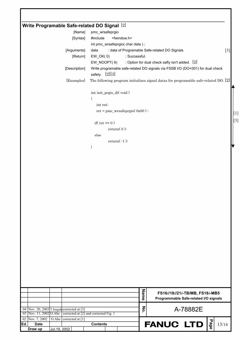
Ed.
Page
Nam
e N
o.
Date ContentsDraw up
FS16i/18i/21i-TB/MB, FS18i-MB5 Programmable Safe-related I/O signals
A-78882E
13/14Jul.19, 2002
02 Nov. 7, 2002 O.Abe corrected at [1]
04 Nov. 20, 2003 T.Inagaki corrected at [3] 03 Nov. 11, 2002 O.Abe corrected at [2] and corrected Fig. 1
Write Programable Safe-related DO Signal [Name] pmc_wrsafeprgio [Syntax] #include <fwindow.h>
int pmc_wrsafeprgio( char data ) ; [Arguments] data : data of Programable Safe-related DO Signals. [Return] EW_OK( 0) : Successful.
EW_NOOPT( 6) : Option for dual check safty isn't added. [Description] Write programable safe-related DO signals via FSSB I/O (DO+001) for dual check
safety. [Examples] The following program initializes signal datas for programable safe-related DO.
int init_prgio_di( void ) int ret; ret = pmc_wrsafeprgio( 0x00 ) ; if( ret == 0 ) return( 0 ); else return( -1 );
[1]
[3]
[2]
[2][3] [2]
[2]
[3]
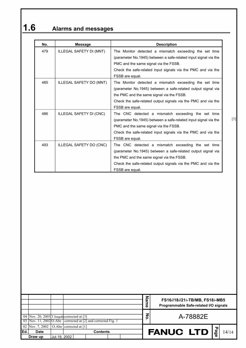
Ed.
Page
Nam
e N
o.
Date ContentsDraw up
FS16i/18i/21i-TB/MB, FS18i-MB5 Programmable Safe-related I/O signals
A-78882E
14/14Jul.19, 2002
02 Nov. 7, 2002 O.Abe corrected at [1]
04 Nov. 20, 2003 T.Inagaki corrected at [3] 03 Nov. 11, 2002 O.Abe corrected at [2] and corrected Fig. 1
1.6 Alarms and messages
No. Message Description
479 ILLEGAL SAFETY DI (MNT) The Monitor detected a mismatch exceeding the set time (parameter No.1945) between a safe-related input signal via the PMC and the same signal via the FSSB. Check the safe-related input signals via the PMC and via the FSSB are equal.
485 ILLEGAL SAFETY DO (MNT) The Monitor detected a mismatch exceeding the set time (parameter No.1945) between a safe-related output signal via the PMC and the same signal via the FSSB. Check the safe-related output signals via the PMC and via the FSSB are equal.
486 ILLEGAL SAFETY DI (CNC) The CNC detected a mismatch exceeding the set time (parameter No.1945) between a safe-related input signal via the PMC and the same signal via the FSSB. Check the safe-related input signals via the PMC and via the FSSB are equal.
493 ILLEGAL SAFETY DO (CNC) The CNC detected a mismatch exceeding the set time (parameter No.1945) between a safe-related output signal via the PMC and the same signal via the FSSB. Check the safe-related output signals via the PMC and via the FSSB are equal.
[3]

TECHNICAL REPORT (MANUAL) NO.TMN 02/071E
Date July. .2002 General Manager of Hardware Laboratory
Dual Check Safety OPERATOR'S MANUAL
Addition and correction of sample system configuration
1. Communicate this report to :
Your information only
GE Fanuc-N, GE Fanuc-E
FANUC Robotics
MILACRON
Machine tool builder
Sales agency
End user
2. Summary for Sales Documents Two sample system configurations are added to dual check safety operator's manual.
3. Notice 4. Attached Document
Drawing No. B-63494EN/01-06
EAO
Original section of issue Senior Vice General Manager
Department Manager
Section Manager
Person in Charge

02.06.26 Arimoto First issue
B-63494EN/01-06
Dual Check Safety OPERATOR'S MANUAL Addition and correction of sample system configuration
1. Type of applied technical documents
Name Dual Check Safety OPERATOR'S MANUAL
Spec.No./Version B-63494EN/01
2. Summary of change
Group Name / Outline New, Add, Correct, Delete
Applicable Date
Basic Function
Optional Function
Unit
Maintenance parts
Notice
Correction
There are three corrections. ・Correction of figure at 10.1.2. ・Delete part of 10.2.1. ・Correction of symbol of part of contact of electromagnetic
contactor in figure at 10.2.5. Another
Two sample system configurations are added. ・For One-path(When two PSMs are used) ・When two protection doors are used in a machine.
EDIT. F A N U C L T DSHEET
DRAW. NO. CUST.
TITLE
1/9DESCRIPTIONDESIG.DATE
Dual Check Safety OPERATOR'S MANUAL Addition and correction ofsample system configuration
01
Change a title of 10.1.1 as follows
10.1.1 For One-path(When one PSM is used)
EDIT. F A N U C L T DSHEET
DRAW. NO. CUST.
TITLE
2/9DESCRIPTIONDESIG.DATE
B-63494EN/01-06

Cange 10.1.2 to 10.1.3 and change figure as follows
10.1.3 For Two-path(When the main side and sub side use a common MCC)
EDIT. F A N U C L T DSHEET
DRAW. NO. CUST.
TITLE
3/9DESCRIPTIONDESIG.DATE
B-63494EN/01-06

Add 10.1.2 as follows
10.1.2 For One-path(When two PSMs are used)
EDIT. F A N U C L T DSHEET
DRAW. NO. CUST.
TITLE
4/9DESCRIPTIONDESIG.DATE
B-63494EN/01-06
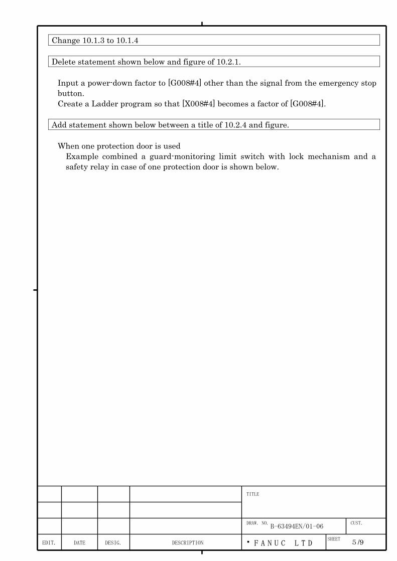
Change 10.1.3 to 10.1.4 Delete statement shown below and figure of 10.2.1.
Input a power-down factor to [G008#4] other than the signal from the emergency stop button. Create a Ladder program so that [X008#4] becomes a factor of [G008#4].
Add statement shown below between a title of 10.2.4 and figure.
When one protection door is used Example combined a guard-monitoring limit switch with lock mechanism and a safety relay in case of one protection door is shown below.
EDIT. F A N U C L T DSHEET
DRAW. NO. CUST.
TITLE
5/9DESCRIPTIONDESIG.DATE
B-63494EN/01-06

EDIT. F A N U C L T DSHEET
DRAW. NO. CUST.
TITLE
6/9DESCRIPTIONDESIG.DATE
B-63494EN/01-06
Add statement and figure shown below between figure and OPERATING PRINCIPLE at 10.2.4..
When two protection doors are used in a safety zone. Example combined two guard-monitoring limit switches with lock mechanism and a safety relay in case of two protection doors in a safety zone is shown below.
+24V
SW11
X00n#n I/O Link I/O UNIT
SGD (DI+001#4)
FSSB I/O UNIT
Y00n#n
PMC SGD (G191#4)
*LGD (F191#0)
Ladder program
Guard-monitoring limit switch 1
Safety relay
【Sample control components】 SW11/SW12,SW21/SW22:
Guard state monitoring switch with forced dissociationmechanism
SW13,SW23: Guard lock switch RY1,RY2,RY3:Safety relay
Guard1 closed Guard2 closed
Guard lock 2Guard lock 1
0V
SW23
Guard-monitoring limit switch 2
SW22 SW21
SW13
SW12
Y00m#m
RY3
0V
RY3
RY3
RY2
RY2 RY2
RY1
RY1 RY1
0V

Change OPERATING PRINCIPLE at 10.2.4 as follows
OPERATING PRINCIPLE When one protection door is used
State of components is shown below.
State of components Guard Guard lock SW1 SW2 SW3 RY1 RY2 RY3 SGD 1 CLOSE LOCK CLOSE CLOSE CLOSE ON ON OFF 1 2 CLOSE UNLOCK CLOSE CLOSE OPEN OFF ON OFF 0 3 OPEN UNLOCK OPEN OPEN OPEN OFF OFF ON 0
In case of no welding of contact in safety relay when state of protection door is changed to open from close and close, transition of 1,2,3,2,1 is occured. RY3 detects whether RY1 and RY2 contacts are made. If an unusual event is detected, SGD input is turned off.
When two protection doors are used in a safety zone This example has construction added a guard-monitoring limit switch to example of "When one protection door is used". Two guard state monitoring switches of two guard-monitoring limit switches are connected series. When at least one guard is open SGD is turned off and the system determines that the guard is open. Two signals are outputed from I/O Link I/O UNIT to open each guard lock switch individually. When at least one guard lock is released by these signals SGD input is turned off and the system determines that the guard is open. State of components is shown below.
State of components Guard1 Guard lock1 Guard2 Guard lock
2
SW1 SW12 SW13 SW21 SW22 SW23 RY1 RY2 RY3 SGD
1 CLOSE LOCK CLOSE LOCK CLOSE CLOSE CLOSE CLOSE CLOSE CLOSE ON ON OFF 1
2 CLOSE UNLOCK CLOSE LOCK CLOSE CLOSE OPE
N
CLOSE CLOSE CLOSE OF
F
ON OFF 0
3 OPE
N
UNLOCK CLOSE LOCK OPE
N
OPE
N
OPE
N
CLOSE CLOSE CLOSE OF
F
OF
F
ON 0
4 CLOSE LOCK CLOSE UNLOCK CLOSE CLOSE CLOSE CLOSE CLOSE OPE
N
OF
F
ON OFF 0
5 CLOSE UNLOCK CLOSE UNLOCK CLOSE CLOSE OPE
N
CLOSE CLOSE OPE
N
OF
F
ON OFF 0
6 OPE
N
UNLOCK CLOSE UNLOCK OPE
N
OPE
N
OPE
N
CLOSE CLOSE OPE
N
OF
F
OF
F
ON 0
EDIT. F A N U C L T DSHEET
DRAW. NO. CUST.
TITLE
7/9DESCRIPTIONDESIG.DATE
B-63494EN/01-06
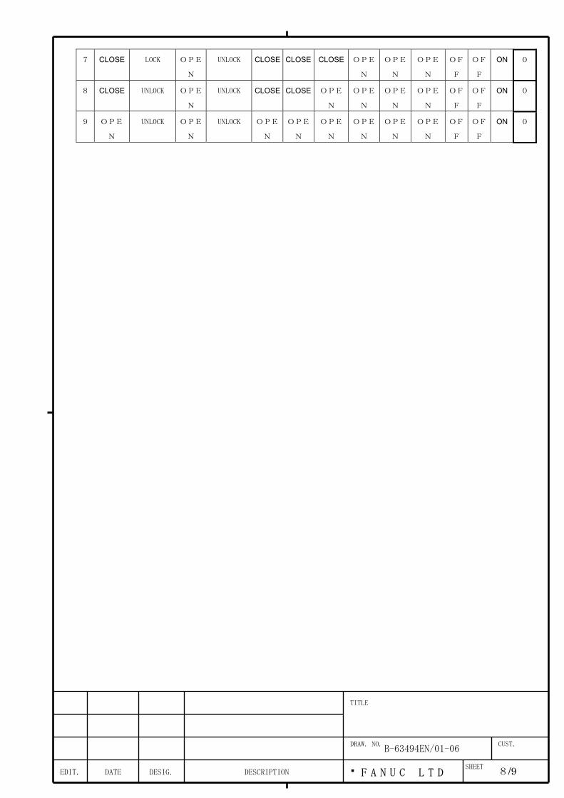
7 CLOSE LOCK OPE
N
UNLOCK CLOSE CLOSE CLOSE OPE
N
OPE
N
OPE
N
OF
F
OF
F
ON 0
8 CLOSE UNLOCK OPE
N
UNLOCK CLOSE CLOSE OPE
N
OPE
N
OPE
N
OPE
N
OF
F
OF
F
ON 0
9 OPE
N
UNLOCK OPE
N
UNLOCK OPE
N
OPE
N
OPE
N
OPE
N
OPE
N
OPE
N
OF
F
OF
F
ON 0
EDIT. F A N U C L T DSHEET
DRAW. NO. CUST.
TITLE
8/9DESCRIPTIONDESIG.DATE
B-63494EN/01-06
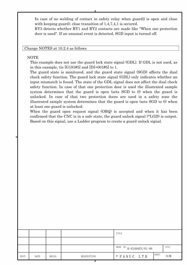
In case of no welding of contact in safety relay when guard2 is open and close with keeping guard1 close transition of 1,4,7,4,1 is occured. RY3 detects whether RY1 and RY2 contacts are made like "When one protection door is used". If an unusual event is detected, SGD input is turned off.
Change NOTES at 10.2.4 as follows
NOTE This example does not use the guard lock state signal (GDL). If GDL is not used, as in this example, tie [G191#5] and [DI+001#5] to 1. The guard state is monitored, and the guard state signal (SGD) affects the dual check safety function. The guard lock state signal (GDL) only indicates whether an input mismatch is found. The state of the GDL signal does not affect the dual check safety function. In case of that one protection door is used the illustrated sample system determines that the guard is open (sets SGD to 0) when the guard is unlocked. In case of that two protection doors are used in a safety zone the illustrated sample system determines that the guard is open (sets SGD to 0) when at least one guard is unlocked. When the guard open request signal (ORQ) is accepted and when it has been confirmed that the CNC is in a safe state, the guard unlock signal (*LGD) is output. Based on this signal, use a Ladder program to create a guard unlock signal.
EDIT. F A N U C L T DSHEET
DRAW. NO. CUST.
TITLE
9/9DESCRIPTIONDESIG.DATE
B-63494EN/01-06

Change figure at 10.2.5 as follows(A symbol of a part of contact of electromagnetic contactor is changed.)
*SMC1 (G191#6)
CX3MCC
Electromagnetic contactor (MAIN MCC)
0V
U V W
200B
200A
+24V
PSM
0V
MCF2 (DO+000#1)
*SMC2 (DI+001#6)
MCF1 (F191#1)
PMC
Y00n#n
FSSB I/O UNIT
I/O Link I/O UNIT
X00n#n
EDIT. F A N U C L T DSHEET
DRAW. NO. CUST.
TITLE
10/9DESCRIPTIONDESIG.DATE
B-63494EN/01-06


