58
B0099 - Robo Claw 2 Channel 5A Motor Controller Data Sheet B0099 - Robo Claw 2 Channel 5A Motor Controller Data Sheet (c) 2010 BasicMicro. All Rights Reserved.
| Date post: | 26-Aug-2018 |
| Category: |
Documents |
| Upload: | truongtruc |
| View: | 222 times |
| Download: | 0 times |

B0099 - Robo Claw 2 Channel 5A Motor ControllerData Sheet
B0099 - Robo Claw 2 Channel 5A Motor Controller Data Sheet
(c) 2010 BasicMicro. All Rights Reserved.
(c) 2010 BasicMicro. All Rights Reserved.
B0099 - Robo Claw 2 Channel 5A Motor Controller Data Sheet
2
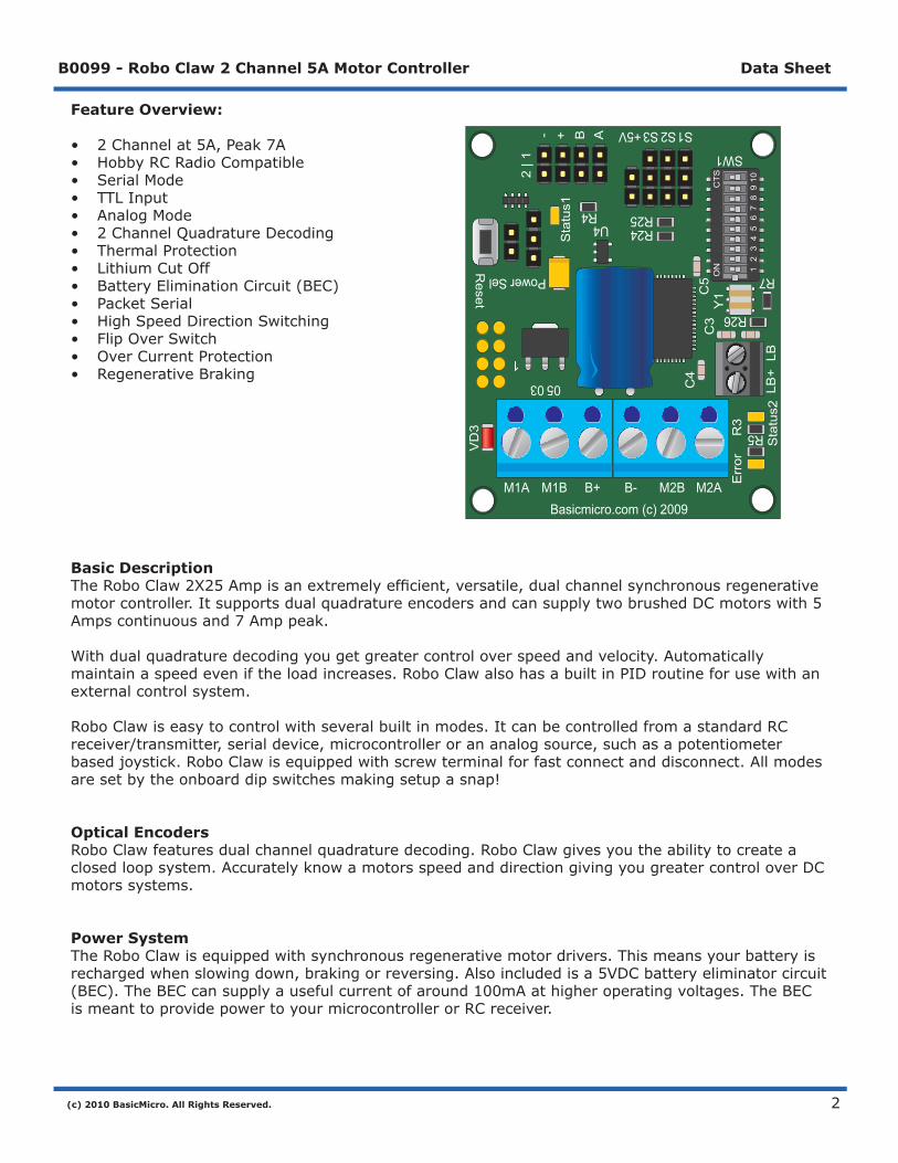
Feature Overview:
• 2Channelat5A,Peak7A• HobbyRCRadioCompatible• SerialMode• TTLInput• AnalogMode• 2ChannelQuadratureDecoding• ThermalProtection• LithiumCutOff• BatteryEliminationCircuit(BEC)• PacketSerial• HighSpeedDirectionSwitching• FlipOverSwitch• OverCurrentProtection• RegenerativeBraking
Basic DescriptionTheRoboClaw2X25Ampisanextremelyefficient,versatile,dualchannelsynchronousregenerativemotorcontroller.ItsupportsdualquadratureencodersandcansupplytwobrushedDCmotorswith5Ampscontinuousand7Amppeak.
Withdualquadraturedecodingyougetgreatercontroloverspeedandvelocity.Automaticallymaintainaspeedeveniftheloadincreases.RoboClawalsohasabuiltinPIDroutineforusewithanexternalcontrolsystem.
RoboClawiseasytocontrolwithseveralbuiltinmodes.ItcanbecontrolledfromastandardRCreceiver/transmitter,serialdevice,microcontrollerorananalogsource,suchasapotentiometerbasedjoystick.RoboClawisequippedwithscrewterminalforfastconnectanddisconnect.Allmodesaresetbytheonboarddipswitchesmakingsetupasnap!
Optical EncodersRoboClawfeaturesdualchannelquadraturedecoding.RoboClawgivesyoutheabilitytocreateaclosedloopsystem.AccuratelyknowamotorsspeedanddirectiongivingyougreatercontroloverDCmotorssystems.
Power SystemTheRoboClawisequippedwithsynchronousregenerativemotordrivers.Thismeansyourbatteryisrechargedwhenslowingdown,brakingorreversing.Alsoincludedisa5VDCbatteryeliminatorcircuit(BEC).TheBECcansupplyausefulcurrentofaround100mAathigheroperatingvoltages.TheBECismeanttoprovidepowertoyourmicrocontrollerorRCreceiver.
R7
R5
SW1
S1S2S3+5V
R26
R24R25R4
U4
C3
LB+
Sta
tus2
Sta
tus1
2 | 1
- + B A
VD
3
Reset
Power Sel
0503
1
Err
orR
3
LB
C4
M1A M1B B+ B- M2B M2ABasicmicro.com (c) 2009
C5
ON
CTS
12
34
56
78
910
Y1
(c) 2010 BasicMicro. All Rights Reserved.
B0099 - Robo Claw 2 Channel 5A Motor Controller Data Sheet
3
R7 R
5
SW
1
S1
S2
S3
+5V
R26
R24
R25
R4
U4
C3
LB+ Status2
Status1
2 | 1-+BA
VD3Reset
Pow
er Sel
0503
1
ErrorR3
LB
C4
M1A
M1B
B+
B-
M2B
M2A
Bas
icm
icro
.com
(c) 2
009
C5ONCTS
12345678910
Y1ONCTS
12345678910
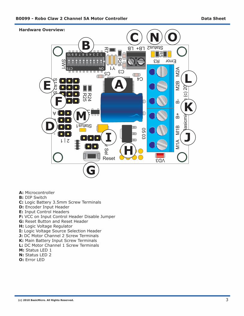
Hardware Overview:
A: MicrocontrollerB: DIPSwitchC: LogicBattery3.5mmScrewTerminalsD: EncoderInputHeaderE: InputControlHeadersF: VCConInputControlHeaderDisableJumperG: ResetButtonandResetHeaderH: LogicVoltageRegulatorI: LogicVoltageSourceSelectionHeaderJ: DCMotorChannel2ScrewTerminalsK: MainBatteryInputScrewTerminalsL: DCMotorChannel1ScrewTerminalsM: StatusLED1N: StatusLED2O: ErrorLED
A
B C
D
EF
GH
I J
K
L
M
N O
(c) 2010 BasicMicro. All Rights Reserved.
B0099 - Robo Claw 2 Channel 5A Motor Controller Data Sheet
4
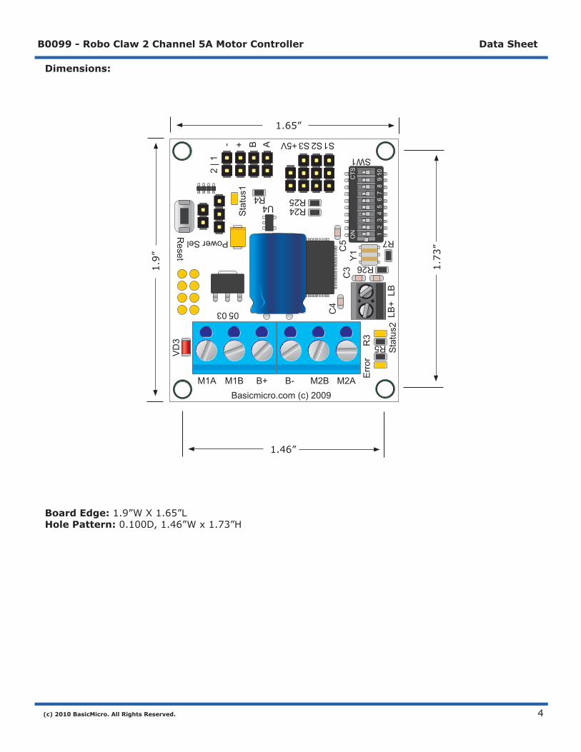
Dimensions:
Board Edge: 1.9”WX1.65”LHole Pattern: 0.100D,1.46”Wx1.73”H
1.65”
1.9”
1.46”1.73”
R7
R5
SW1
S1S2S3+5V
R26
R24R25R4
U4
C3
LB+
Sta
tus2
Sta
tus1
2 | 1
- + B A
VD
3
Reset
Power Sel
0503
1
Err
orR
3
LB
C4
M1A M1B B+ B- M2B M2ABasicmicro.com (c) 2009
C5 O
NC
TS
12
34
56
78
910
Y1
ON
CTS
12
34
56
78
910
(c) 2010 BasicMicro. All Rights Reserved.
B0099 - Robo Claw 2 Channel 5A Motor Controller Data Sheet
5
R7
R5
SW1
S1S2 S3 +5V
R26
R24R25 R4
U4
C3
LB+
Status2
Status1
2 | 1-+BA
VD
3
Res
et
Power Sel
05 03
1
Error
R3
LB
C4
M1AM1BB+B-M2BM2ABasicmicro.com (c) 2009
C5
ON
CTS
12
34
56
78
910
Y1
ON
CTS
12
34
56
78
910
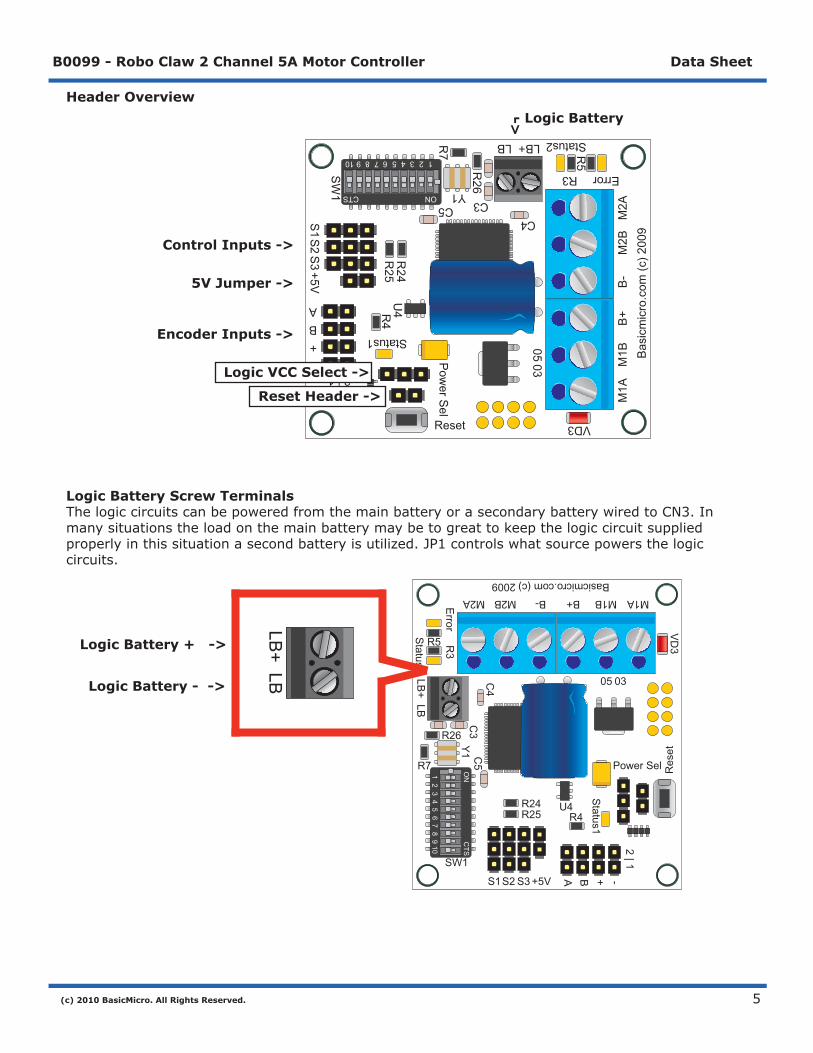
Header Overview
Logic Battery Screw TerminalsThelogiccircuitscanbepoweredfromthemainbatteryorasecondarybatterywiredtoCN3.Inmanysituationstheloadonthemainbatterymaybetogreattokeepthelogiccircuitsuppliedproperlyinthissituationasecondbatteryisutilized.JP1controlswhatsourcepowersthelogiccircuits.
R7 R
5
SW
1
S1
S2
S3
+5V
R26
R24
R25
R4
U4
C3
LB+ Status2
Status1
2 | 1-+BA
VD3Reset
Pow
er Sel
0503
1
ErrorR3
LB
C4
M1A
M1B
B+
B-
M2B
M2A
Bas
icm
icro
.com
(c) 2
009
C5ONCTS
12345678910
Y1ONCTS
12345678910
- Logic Battery
Encoder Inputs ->
Control Inputs ->
5V Jumper ->->
Logic Battery + ->
Logic Battery - ->
LB+
LB
Reset Header ->
Logic VCC Select ->
(c) 2010 BasicMicro. All Rights Reserved.
B0099 - Robo Claw 2 Channel 5A Motor Controller Data Sheet
6
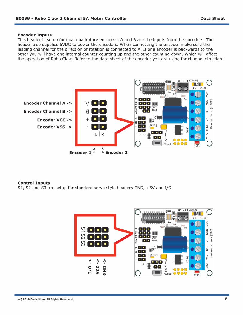
Encoder InputsThisheaderissetupfordualquadratureencoders.AandBaretheinputsfromtheencoders.Theheaderalsosupplies5VDCtopowertheencoders.WhenconnectingtheencodermakesuretheleadingchannelforthedirectionofrotationisconnectedtoA.Ifoneencoderisbackwardstotheotheryouwillhaveoneinternalcountercountingupandtheothercountingdown.WhichwillaffecttheoperationofRoboClaw.Refertothedatasheetoftheencoderyouareusingforchanneldirection.
Control InputsS1,S2andS3aresetupforstandardservostyleheadersGND,+5VandI/O.
I/O
->
VC
C -
>
GN
D -
>
R7 R
5
SW
1
S1
S2
S3
+5V
R26
R24
R25
R4
U4
C3
LB+ Status2
Status1
2 | 1-+BA
VD3Reset
Pow
er Sel
0503
1
ErrorR3
LB
C4
M1A
M1B
B+
B-
M2B
M2A
Bas
icm
icro
.com
(c) 2
009
C5ONCTS
12345678910
Y1ONCTS
12345678910
Encoder 1 -<
-
<-
- Encoder 2
Encoder VCC ->
Encoder VSS ->
Encoder Channel A ->
Encoder Channel B ->
2 | 1-+BA
R7 R
5
SW
1
S1
S2
S3
+5V
R26
R24
R25
R4
U4
C3
LB+ Status2
Status1
2 | 1-+BA
VD3Reset
Pow
er Sel
0503
1
ErrorR3
LB
C4
M1A
M1B
B+
B-
M2B
M2A
Bas
icm
icro
.com
(c) 2
009
C5ONCTS
12345678910
Y1ONCTS
12345678910
S1
S2
S3

(c) 2010 BasicMicro. All Rights Reserved.
B0099 - Robo Claw 2 Channel 5A Motor Controller Data Sheet
7
BEC JumperVCConcontrolinputheadersS1,S2andS3canbeturnedofforonbythejumperJP3.WhenBECjumperisinstalled5VDCissuppliedfromthelogicsupplytothecenterpinofthe3pinheaders.InsomesystemstheRCreceivermayhaveitsownsupplyandwillconflictwiththeRoboClawlogicsupply.RemovingtheBECjumperdisablesVCConS1,S2andS3headers.
Reset HeaderTheresetheaderallowsexternaldeviceslikeamicrocontrollertohardresetRoboClaw.The2pinheaderisGNDandRST.ToexternallyresetRoboClawshorttheRSTpintoGND(VSS).
R7R
5
SW
1
S1
S2
S3
+5V
R26
R24
R25
R4
U4
C3
LB+Status2
Status1
2 | 1-+BA
VD3 Reset
Pow
er S
el
0503
1
Error R3
LB
C4
M1A
M1B
B+
B-
M2B
M2A
Basicm
icro.com (c) 2009
C5ON CTS
1 2 3 4 5 6 7 8 9 10
Y1 ON CTS
1 2 3 4 5 6 7 8 9 10
+5V
R7
R5
SW1
S1S2 S3 +5V
R26
R24R25 R4
U4
C3
LB+
Status2
Status1
2 | 1-+BA
VD
3
Res
et
Power Sel
05 03
1
Error
R3
LB
C4
M1AM1BB+B-M2BM2ABasicmicro.com (c) 2009
C5
ON
CTS
12
34
56
78
910
Y1
ON
CTS
12
34
56
78
910
VSS ->
RST ->
Res
et

(c) 2010 BasicMicro. All Rights Reserved.
B0099 - Robo Claw 2 Channel 5A Motor Controller Data Sheet
8
Logic Supply SelectTheRoboClawlogicrequires5VDCwhichisprovidedfromtheonboardregulator.Theregulatorsourcevoltageissetwiththelogicsupplyjumper.Pins1-2=LogicBattery,2-3=MainBattery.JP1labelisshownupsidedowntomatchtheorientationontheRoboClaw.
<- 1
<- 2
<- 3
R7
R5
SW1
S1S2 S3 +5V
R26
R24R25 R4
U4
C3
LB+
Status2
Status1
2 | 1-+BA
VD
3
Res
et
Power Sel
05 03
1
Error
R3
LB
C4
M1AM1BB+B-M2BM2ABasicmicro.com (c) 2009
C5
ON
CTS
12
34
56
78
910
Y1
ON
CTS
12
34
56
78
910
(c) 2010 BasicMicro. All Rights Reserved.
B0099 - Robo Claw 2 Channel 5A Motor Controller Data Sheet
9
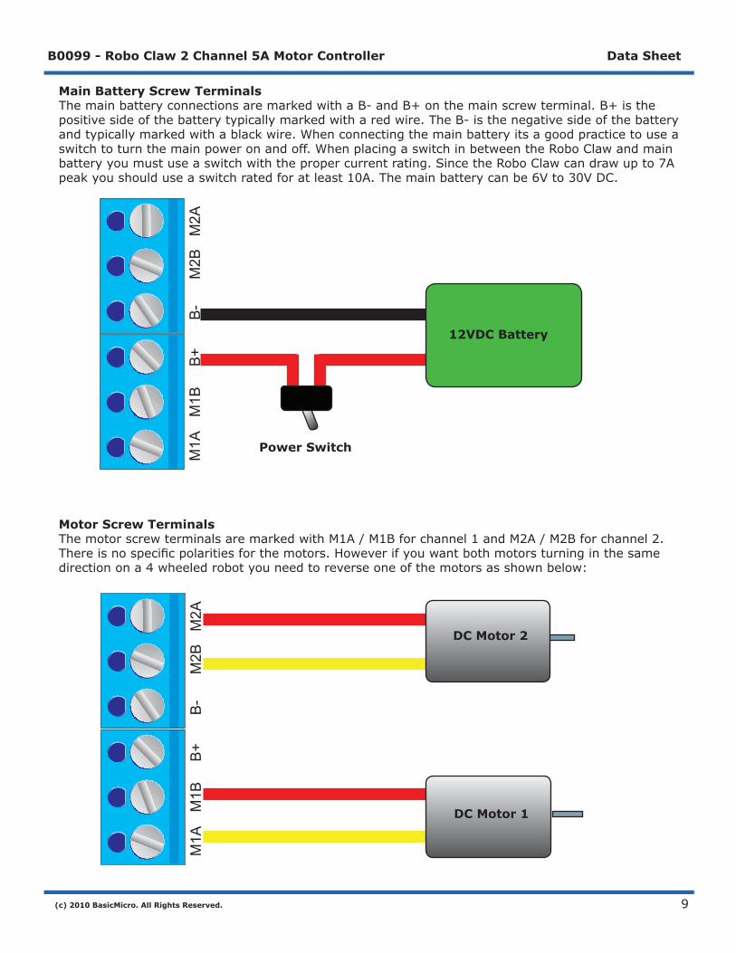
Main Battery Screw TerminalsThemainbatteryconnectionsaremarkedwithaB-andB+onthemainscrewterminal.B+isthepositivesideofthebatterytypicallymarkedwitharedwire.TheB-isthenegativesideofthebatteryandtypicallymarkedwithablackwire.Whenconnectingthemainbatteryitsagoodpracticetouseaswitchtoturnthemainpoweronandoff.WhenplacingaswitchinbetweentheRoboClawandmainbatteryyoumustuseaswitchwiththepropercurrentrating.SincetheRoboClawcandrawupto7Apeakyoushoulduseaswitchratedforatleast10A.Themainbatterycanbe6Vto30VDC.
Motor Screw TerminalsThemotorscrewterminalsaremarkedwithM1A/M1Bforchannel1andM2A/M2Bforchannel2.Thereisnospecificpolaritiesforthemotors.Howeverifyouwantbothmotorsturninginthesamedirectionona4wheeledrobotyouneedtoreverseoneofthemotorsasshownbelow:
M1A
M1B
B+
B-
M2B
M2A
DC Motor 1
12VDC Battery
Power Switch
M1A
M1B
B+
B-
M2B
M2A
DC Motor 2
DC Motor 1
(c) 2010 BasicMicro. All Rights Reserved.
B0099 - Robo Claw 2 Channel 5A Motor Controller Data Sheet
10
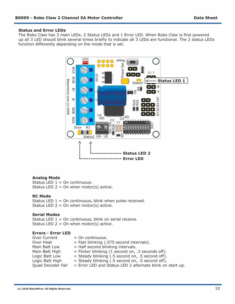
Status and Error LEDsTheRoboClawhas3mainLEDs.2StatusLEDsand1ErrorLED.WhenRoboClawisfirstpoweredupall3LEDshouldblinkseveraltimesbrieflytoindicateall3LEDsarefunctional.The2statusLEDsfunctiondifferentlydependingonthemodethatisset.
Analog Mode StatusLED1=Oncontinuous. StatusLED2=Onwhenmotor(s)active.
RC Mode StatusLED1=Oncontinuous,blinkwhenpulsereceived. StatusLED2=Onwhenmotor(s)active.
Serial Modes StatusLED1=Oncontinuous,blinkonserialreceive. StatusLED2=Onwhenmotor(s)active.
Errors - Error LED OverCurrent =Oncontinuous. OverHeat =Fastblinking(.075secondintervals). MainBattLow =Halfsecondblinkingintervals. MainBattHigh =Flickerblinking(1secondon,.3secondsoff). LogicBattLow =Steadyblinking(.5secondon,.5secondoff). LogicBattHigh =Steadyblinking(.5secondon,.5secondoff). QuadDecoderFail =ErrorLEDandStatusLED2alternateblinkonstartup.
----------------------- Error LED----------------- Status LED 2
<-----
<--------
R7R
5
SW
1
S1
S2
S3
+5V
R26
R24
R25
R4
U4
C3
LB+Status2
Status1
2 | 1-+BA
VD3 Reset
Pow
er S
el
0503
1
Error R3
LB
C4
M1A
M1B
B+
B-
M2B
M2A
Basicm
icro.com (c) 2009
C5ON CTS
1 2 3 4 5 6 7 8 9 10
Y1 ON CTS
1 2 3 4 5 6 7 8 9 10
<---- Status LED 1
(c) 2010 BasicMicro. All Rights Reserved.
B0099 - Robo Claw 2 Channel 5A Motor Controller Data Sheet
11
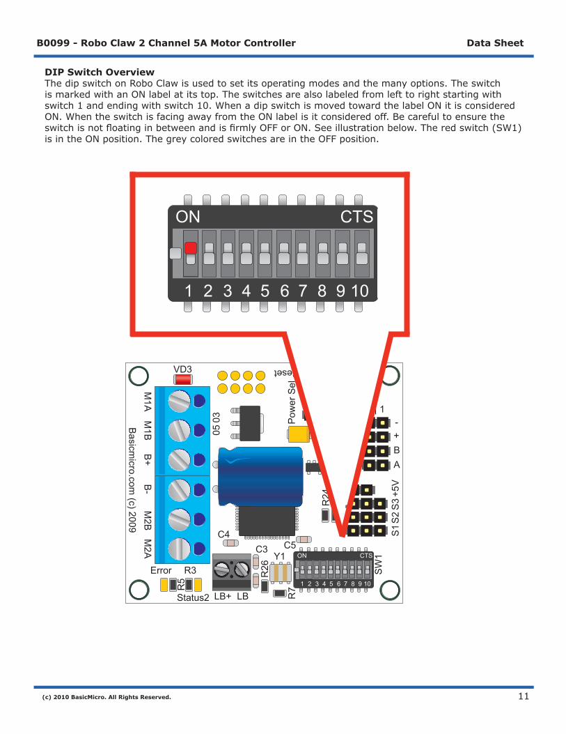
DIP Switch OverviewThedipswitchonRoboClawisusedtosetitsoperatingmodesandthemanyoptions.TheswitchismarkedwithanONlabelatitstop.Theswitchesarealsolabeledfromlefttorightstartingwithswitch1andendingwithswitch10.WhenadipswitchismovedtowardthelabelONitisconsideredON.WhentheswitchisfacingawayfromtheONlabelisitconsideredoff.BecarefultoensuretheswitchisnotfloatinginbetweenandisfirmlyOFForON.Seeillustrationbelow.Theredswitch(SW1)isintheONposition.ThegreycoloredswitchesareintheOFFposition.
R7R
5
SW
1
S1
S2
S3
+5V
R26
R24
R25
R4
U4
C3
LB+Status2
Status1
2 | 1-+BA
VD3 Reset
Pow
er S
el
0503
1
Error R3
LB
C4
M1A
M1B
B+
B-
M2B
M2A
Basicm
icro.com (c) 2009
C5ON CTS
1 2 3 4 5 6 7 8 9 10
Y1 ON CTS
1 2 3 4 5 6 7 8 9 10
ON CTS
1 2 3 4 5 6 7 8 9 10

(c) 2010 BasicMicro. All Rights Reserved.
B0099 - Robo Claw 2 Channel 5A Motor Controller Data Sheet
12
Low Voltage CutoffRoboClawhasabuiltinlowvoltageprotection.Thishastwomainpurposed.ToprotectRoboClawfromrunningerraticallywhenthemainbatterylevelgetstolowandprotectaLithiumbatteryfrombeingdamaged.
Voltage SW8 SW9 SW10Not Monitored OFF OFF OFFLead Acid - Auto ON OFF OFF2- Cell (6V Cutoff) OFF ON OFF3- Cell (9V Cutoff) ON ON OFF4- Cell (12V Cutoff) OFF OFF ON5- Cell (15V Cutoff) ON OFF ON6- Cell (18V Cutoff) OFF ON ON7- Cell (21V Cutoff) ON ON ON
(c) 2010 BasicMicro. All Rights Reserved.
B0099 - Robo Claw 2 Channel 5A Motor Controller Data Sheet
13
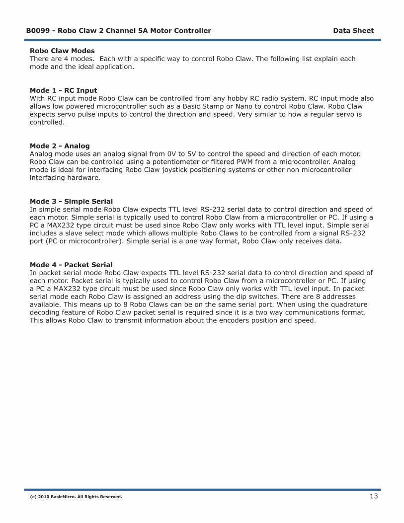
Robo Claw ModesThereare4modes.EachwithaspecificwaytocontrolRoboClaw.Thefollowinglistexplaineachmodeandtheidealapplication.
Mode 1 - RC InputWithRCinputmodeRoboClawcanbecontrolledfromanyhobbyRCradiosystem.RCinputmodealsoallowslowpoweredmicrocontrollersuchasaBasicStamporNanotocontrolRoboClaw.RoboClawexpectsservopulseinputstocontrolthedirectionandspeed.Verysimilartohowaregularservoiscontrolled.
Mode 2 - AnalogAnalogmodeusesananalogsignalfrom0Vto5Vtocontrolthespeedanddirectionofeachmotor.RoboClawcanbecontrolledusingapotentiometerorfilteredPWMfromamicrocontroller.AnalogmodeisidealforinterfacingRoboClawjoystickpositioningsystemsorothernonmicrocontrollerinterfacinghardware.
Mode 3 - Simple SerialInsimpleserialmodeRoboClawexpectsTTLlevelRS-232serialdatatocontroldirectionandspeedofeachmotor.SimpleserialistypicallyusedtocontrolRoboClawfromamicrocontrollerorPC.IfusingaPCaMAX232typecircuitmustbeusedsinceRoboClawonlyworkswithTTLlevelinput.SimpleserialincludesaslaveselectmodewhichallowsmultipleRoboClawstobecontrolledfromasignalRS-232port(PCormicrocontroller).Simpleserialisaonewayformat,RoboClawonlyreceivesdata.
Mode 4 - Packet SerialInpacketserialmodeRoboClawexpectsTTLlevelRS-232serialdatatocontroldirectionandspeedofeachmotor.PacketserialistypicallyusedtocontrolRoboClawfromamicrocontrollerorPC.IfusingaPCaMAX232typecircuitmustbeusedsinceRoboClawonlyworkswithTTLlevelinput.InpacketserialmodeeachRoboClawisassignedanaddressusingthedipswitches.Thereare8addressesavailable.Thismeansupto8RoboClawscanbeonthesameserialport.WhenusingthequadraturedecodingfeatureofRoboClawpacketserialisrequiredsinceitisatwowaycommunicationsformat.ThisallowsRoboClawtotransmitinformationabouttheencoderspositionandspeed.

(c) 2010 BasicMicro. All Rights Reserved.
B0099 - Robo Claw 2 Channel 5A Motor Controller Data Sheet
14
RCInput
(c) 2010 BasicMicro. All Rights Reserved.
B0099 - Robo Claw 2 Channel 5A Motor Controller Data Sheet
15
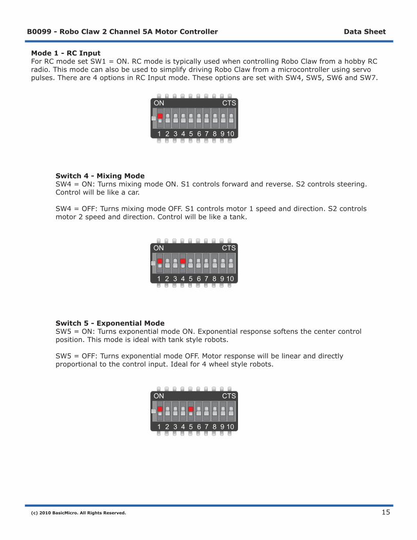
Mode 1 - RC InputForRCmodesetSW1=ON.RCmodeistypicallyusedwhencontrollingRoboClawfromahobbyRCradio.ThismodecanalsobeusedtosimplifydrivingRoboClawfromamicrocontrollerusingservopulses.Thereare4optionsinRCInputmode.TheseoptionsaresetwithSW4,SW5,SW6andSW7.
Switch 4 - Mixing Mode SW4=ON:TurnsmixingmodeON.S1controlsforwardandreverse.S2controlssteering. Controlwillbelikeacar. SW4=OFF:TurnsmixingmodeOFF.S1controlsmotor1speedanddirection.S2controls motor2speedanddirection.Controlwillbelikeatank.
Switch 5 - Exponential Mode SW5=ON:TurnsexponentialmodeON.Exponentialresponsesoftensthecentercontrol position.Thismodeisidealwithtankstylerobots. SW5=OFF:TurnsexponentialmodeOFF.Motorresponsewillbelinearanddirectly proportionaltothecontrolinput.Idealfor4wheelstylerobots.
ON CTS
1 2 3 4 5 6 7 8 9 10
ON CTS
1 2 3 4 5 6 7 8 9 10
ON CTS
1 2 3 4 5 6 7 8 9 10

(c) 2010 BasicMicro. All Rights Reserved.
B0099 - Robo Claw 2 Channel 5A Motor Controller Data Sheet
16
Switch 6 - MCU or RC Control SW6=ON:TurnsMCUcontrolmodeON.RoboClawwillcontinuetoexecutelastpulsereceived untilnewpulsereceived.Signallostfailsafeandautocalibrationareoffinthismode. SW6=OFF:TurnsRCcontrolmodeON.RoboClawwillcalibratethecenterandendpoints automaticallytomaximizestickthrow.Thismodeincludesafailsafe.Ifcontrolinputislost, RoboClawwillshutdown.
Switch 7 - Flip Switch Input SW7=ON:Flipswitchinputrequiresservopulse.Pulsegreaterthan1.5mswillreverse steeringcontrol.Theflipswitchistypicallyusedinrobotcombatstoautomaticallyreversethe controlsifarobotisflippedover. SW7=OFF:FlipswitchinputexpectsTTLcontrolsignal.0Vforflippedand5Vfornormal.
ON CTS
1 2 3 4 5 6 7 8 9 10
ON CTS
1 2 3 4 5 6 7 8 9 10

(c) 2010 BasicMicro. All Rights Reserved.
B0099 - Robo Claw 2 Channel 5A Motor Controller Data Sheet
17
Servo Pulse RangesTheRoboClawexpectsRCservopulsesonS1andS2todrivethemotorswhenthedipswitchesaresetforRCmode.Thecenterpointsarecalibratedatstartup.1000usisthedefaultforfullreverseand2000usisthedefaultforfullforward.TheRoboClawwillautocalibratetheserangesonthefly.Ifapulsesmallerthan1000usorlargerthan2000usisdetectedthenewpulseswillbesetasthenewrange.
Pulse Function1000us FullReverse2000us FullForward
(c) 2010 BasicMicro. All Rights Reserved.
B0099 - Robo Claw 2 Channel 5A Motor Controller Data Sheet
18
R7
R5
SW1
S1S2S3+5V
R26
R24R25R4
U4
C3
LB+
Sta
tus2
Sta
tus1
2 | 1
- + B A
VD
3
Reset
Power Sel
0503
1
Err
orR
3
LB
C4
M1A M1B B+ B- M2B M2ABasicmicro.com (c) 2009
C5 O
NC
TS
12
34
56
78
910
Y1
ON
CTS
12
34
56
78
910
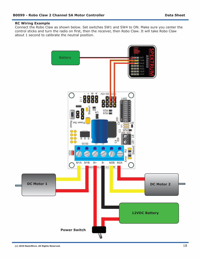
RC Wiring ExampleConnecttheRoboClawasshownbelow.SetswitchesSW1andSW4toON.Makesureyoucenterthecontrolsticksandturntheradioonfirst,thenthereceiver,thenRoboClaw.ItwilltakeRoboClawabout1secondtocalibratetheneutralposition.
DC Motor 1 DC Motor 2
Power Switch
12VDC Battery
BAT
-
THRAILEELERUDGERAUX
+ ~
SPEKTRUM
AR
6000Battery
(c) 2010 BasicMicro. All Rights Reserved.
B0099 - Robo Claw 2 Channel 5A Motor Controller Data Sheet
19
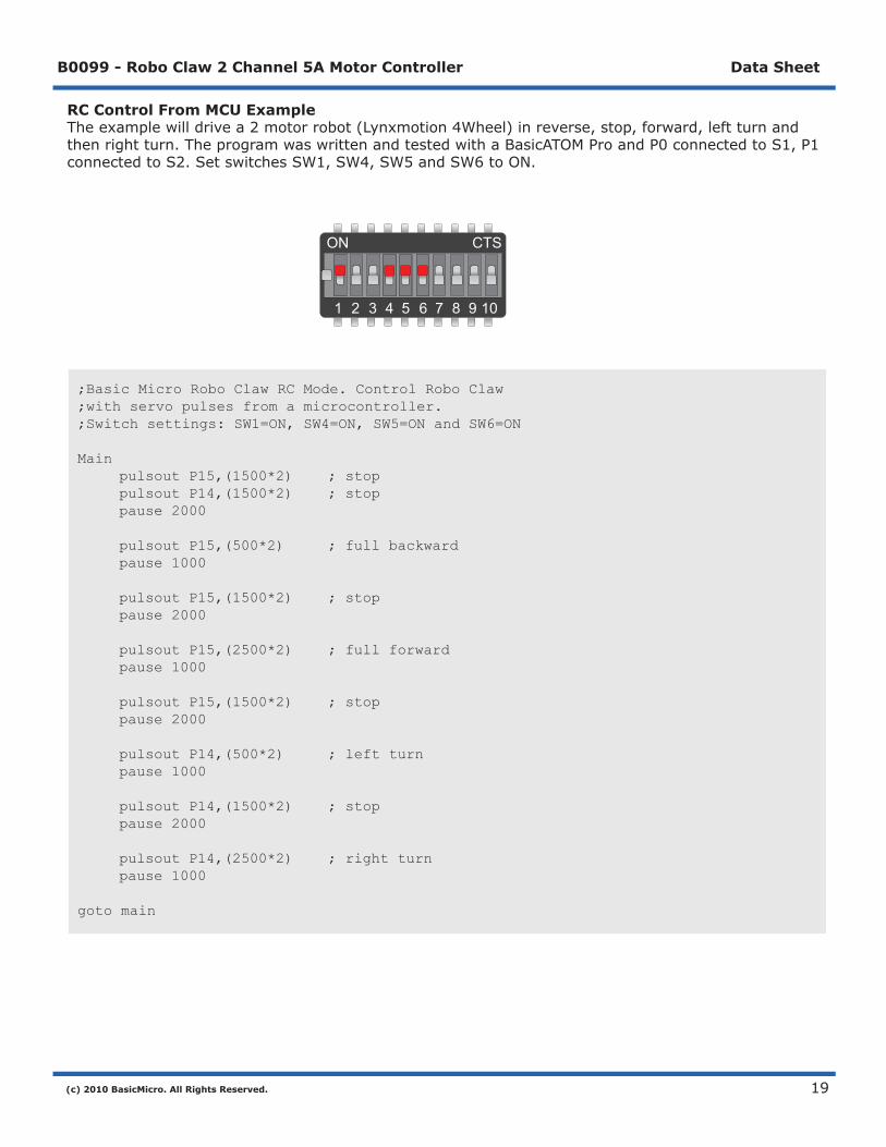
RC Control From MCU ExampleTheexamplewilldrivea2motorrobot(Lynxmotion4Wheel)inreverse,stop,forward,leftturnandthenrightturn.TheprogramwaswrittenandtestedwithaBasicATOMProandP0connectedtoS1,P1connectedtoS2.SetswitchesSW1,SW4,SW5andSW6toON.
;Basic Micro Robo Claw RC Mode. Control Robo Claw ;with servo pulses from a microcontroller. ;Switch settings: SW1=ON, SW4=ON, SW5=ON and SW6=ON
Main pulsout P15,(1500*2) ; stop pulsout P14,(1500*2) ; stop pause 2000
pulsout P15,(500*2) ; full backward pause 1000 pulsout P15,(1500*2) ; stop pause 2000 pulsout P15,(2500*2) ; full forward pause 1000
pulsout P15,(1500*2) ; stop pause 2000 pulsout P14,(500*2) ; left turn pause 1000 pulsout P14,(1500*2) ; stop pause 2000 pulsout P14,(2500*2) ; right turn pause 1000 goto main
ON CTS
1 2 3 4 5 6 7 8 9 10

(c) 2010 BasicMicro. All Rights Reserved.
B0099 - Robo Claw 2 Channel 5A Motor Controller Data Sheet
20
AnalogInput
(c) 2010 BasicMicro. All Rights Reserved.
B0099 - Robo Claw 2 Channel 5A Motor Controller Data Sheet
21
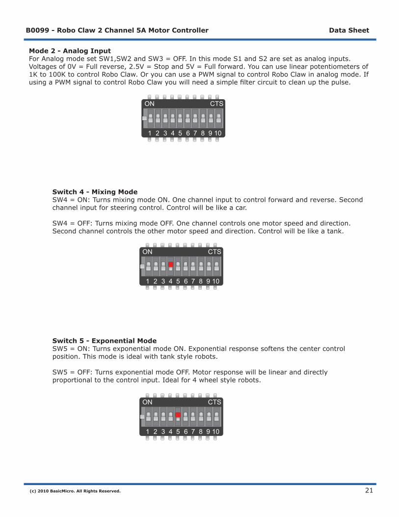
Mode 2 - Analog InputForAnalogmodesetSW1,SW2andSW3=OFF.InthismodeS1andS2aresetasanaloginputs.Voltagesof0V=Fullreverse,2.5V=Stopand5V=Fullforward.Youcanuselinearpotentiometersof1Kto100KtocontrolRoboClaw.OryoucanuseaPWMsignaltocontrolRoboClawinanalogmode.IfusingaPWMsignaltocontrolRoboClawyouwillneedasimplefiltercircuittocleanupthepulse.
Switch 4 - Mixing Mode SW4=ON:TurnsmixingmodeON.Onechannelinputtocontrolforwardandreverse.Second channelinputforsteeringcontrol.Controlwillbelikeacar. SW4=OFF:TurnsmixingmodeOFF.Onechannelcontrolsonemotorspeedanddirection. Secondchannelcontrolstheothermotorspeedanddirection.Controlwillbelikeatank.
Switch 5 - Exponential Mode SW5=ON:TurnsexponentialmodeON.Exponentialresponsesoftensthecentercontrol position.Thismodeisidealwithtankstylerobots. SW5=OFF:TurnsexponentialmodeOFF.Motorresponsewillbelinearanddirectly proportionaltothecontrolinput.Idealfor4wheelstylerobots.
ON CTS
1 2 3 4 5 6 7 8 9 10
ON CTS
1 2 3 4 5 6 7 8 9 10
ON CTS
1 2 3 4 5 6 7 8 9 10

(c) 2010 BasicMicro. All Rights Reserved.
B0099 - Robo Claw 2 Channel 5A Motor Controller Data Sheet
22
Switch 6 - 4x Sensitivity SW6=ON:Turns4xsensitivityON.WiththisoptiontheRoboClawinputcontrolvoltagesare nowmoresensitive.Voltageof1.875V=Fullreverse,2.5V=Stopand3.125V=Fullforward. ThisoptioncanalsobeusedtodriveRoboClawfroma3.3vmicrocontroller. SW6=OFF:Turns4xsensitivityOFF.Normalanalogvoltagesapply.Voltagesof0V=Full reverse,2.5V=Stopand5V=Fullforward.
ON CTS
1 2 3 4 5 6 7 8 9 10
(c) 2010 BasicMicro. All Rights Reserved.
B0099 - Robo Claw 2 Channel 5A Motor Controller Data Sheet
23
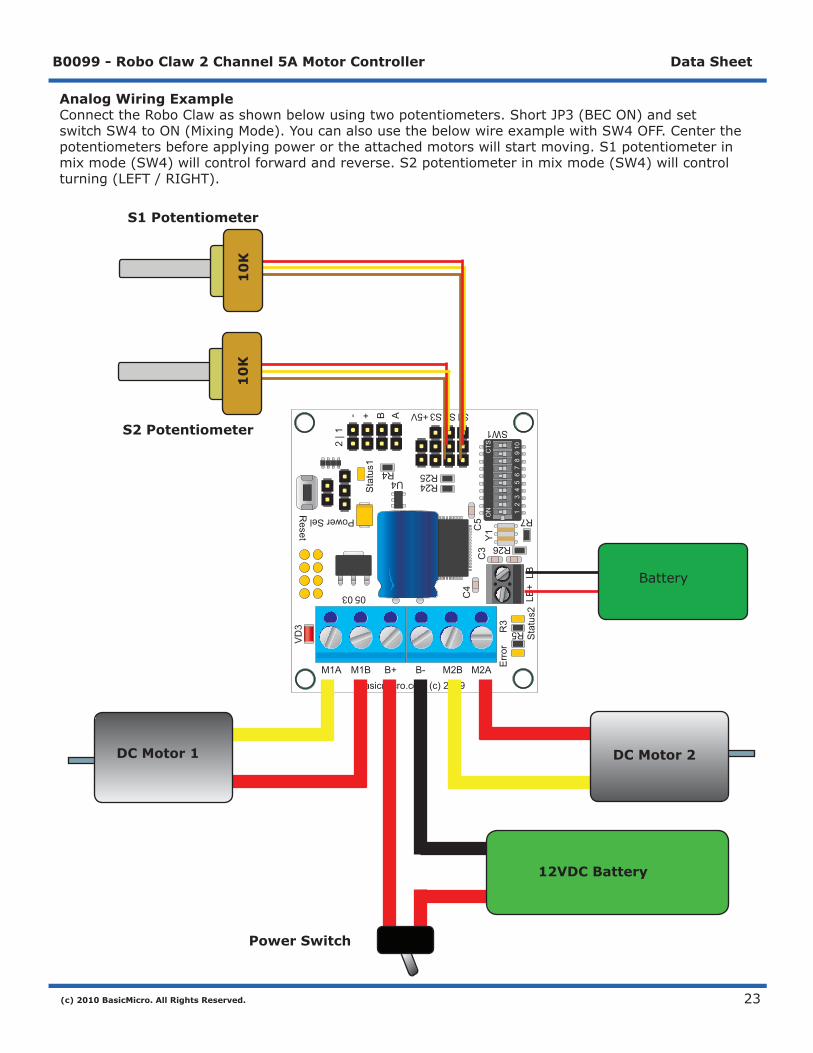
Analog Wiring ExampleConnecttheRoboClawasshownbelowusingtwopotentiometers.ShortJP3(BECON)andsetswitchSW4toON(MixingMode).YoucanalsousethebelowwireexamplewithSW4OFF.Centerthepotentiometersbeforeapplyingpowerortheattachedmotorswillstartmoving.S1potentiometerinmixmode(SW4)willcontrolforwardandreverse.S2potentiometerinmixmode(SW4)willcontrolturning(LEFT/RIGHT).
R7
R5
SW1
S1S2S3+5V
R26
R24R25R4
U4
C3
LB+
Sta
tus2
Sta
tus1
2 | 1
- + B A
VD
3
Reset
Power Sel
0503
1
Err
orR
3
LB
C4
M1A M1B B+ B- M2B M2ABasicmicro.com (c) 2009
C5 O
NC
TS
12
34
56
78
910
Y1
ON
CTS
12
34
56
78
910
DC Motor 1 DC Motor 2
Power Switch
12VDC Battery
Battery
10
K1
0K
S1 Potentiometer
S2 Potentiometer

(c) 2010 BasicMicro. All Rights Reserved.
B0099 - Robo Claw 2 Channel 5A Motor Controller Data Sheet
24
SimpleSerial

(c) 2010 BasicMicro. All Rights Reserved.
B0099 - Robo Claw 2 Channel 5A Motor Controller Data Sheet
25
Mode 3 - Simple SerialSimpleSerialmodesetSW1=OFF,SW2=ONandSW3=OFF.InthismodeS1acceptsTTLlevelbytecommands.RoboClawisreceiveonlyanduses8N1formatwhichis8bits,noparitybitsand1stopbit.IfyourusingamicrocontrolleryoucaninterfacedirectlytoRoboClaw.IfyourusingaPCalevelshiftingcircuitisrequired(MAX232).Thebaudrateissetbythedipswitches.
Switch 1 - Slave Select SW1=ON:TurnsslaveselectON.SlaveselectisusedwhenmorethanoneRoboClawison thesameserialbuss.WhenslaveselectissettoONtheS2pinbecomestheselectpin.SetS2 high(5V)andRoboClawwillexecutethenextcommands.SetS2low(0V)andRoboClawswill ignoreallsentcommands.
Simple Serial Slave SettinguptheRoboClawforserialslaveisstraightforward.MakesureallRoboClawsshare acommonsignalground(GND)shownbytheblackwire.P0(Brownline)isconnectedtoS1 ofall3RoboClawswhichistheserialinoftheRoboClaw.P1,P2andP3areconnectedtoS2. OnlyoneMCUpinisconnectedtoeachRoboClawsS2pin.ToenableRoboClawholdS2high otherwiseanycommandssentisignored.
ON CTS
1 2 3 4 5 6 7 8 9 10
ON CTS
1 2 3 4 5 6 7 8 9 10
MCU
GND -P0 -P1 -P2 -P3 -
R7
R5
SW1
S1S2S3+5V
R26
R24R25R4
U4
C3
LB+
Sta
tus2
Sta
tus1
2 | 1
- + B A
VD
3
Reset
Power Sel
0503
1
Err
orR
3
LB
C4
M1A M1B B+ B- M2B M2ABasicmicro.com (c) 2009
C5 O
NC
TS
12
34
56
78
910
Y1
ON
CTS
12
34
56
78
910
R7
R5
SW1
S1S2S3+5V
R26
R24R25R4
U4
C3
LB+
Sta
tus2
Sta
tus1
2 | 1
- + B A
VD
3
Reset
Power Sel
0503
1
Err
orR
3
LB
C4
M1A M1B B+ B- M2B M2ABasicmicro.com (c) 2009
C5 O
NC
TS
12
34
56
78
910
Y1
ON
CTS
12
34
56
78
910
R7
R5
SW1
S1S2S3+5V
R26
R24R25R4
U4
C3
LB+
Sta
tus2
Sta
tus1
2 | 1
- + B A
VD
3
Reset
Power Sel
0503
1
Err
orR
3
LB
C4
M1A M1B B+ B- M2B M2ABasicmicro.com (c) 2009
C5 O
NC
TS
12
34
56
78
910
Y1
ON
CTS
12
34
56
78
910
(c) 2010 BasicMicro. All Rights Reserved.
B0099 - Robo Claw 2 Channel 5A Motor Controller Data Sheet
26
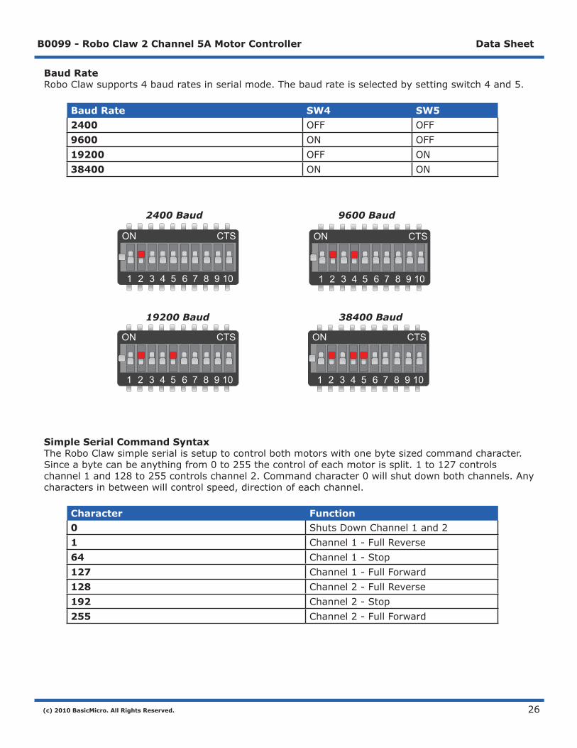
Baud RateRoboClawsupports4baudratesinserialmode.Thebaudrateisselectedbysettingswitch4and5.
Baud Rate SW4 SW52400 OFF OFF9600 ON OFF19200 OFF ON38400 ON ON
2400 Baud 9600 Baud
19200 Baud 38400 Baud
Simple Serial Command SyntaxTheRoboClawsimpleserialissetuptocontrolbothmotorswithonebytesizedcommandcharacter.Sinceabytecanbeanythingfrom0to255thecontrolofeachmotorissplit.1to127controlschannel1and128to255controlschannel2.Commandcharacter0willshutdownbothchannels.Anycharactersinbetweenwillcontrolspeed,directionofeachchannel.
Character Function0 ShutsDownChannel1and21 Channel1-FullReverse64 Channel1-Stop127 Channel1-FullForward128 Channel2-FullReverse192 Channel2-Stop255 Channel2-FullForward
ON CTS
1 2 3 4 5 6 7 8 9 10
ON CTS
1 2 3 4 5 6 7 8 9 10
ON CTS
1 2 3 4 5 6 7 8 9 10
ON CTS
1 2 3 4 5 6 7 8 9 10
(c) 2010 BasicMicro. All Rights Reserved.
B0099 - Robo Claw 2 Channel 5A Motor Controller Data Sheet
27
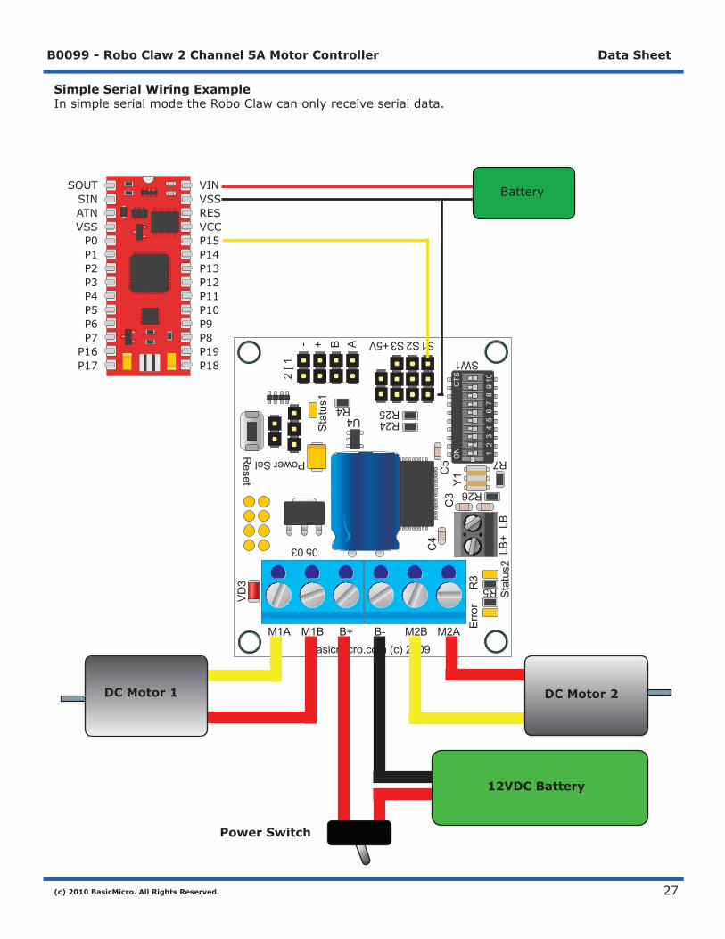
Simple Serial Wiring ExampleInsimpleserialmodetheRoboClawcanonlyreceiveserialdata.
R7
R5
SW1
S1S2S3+5V
R26
R24R25R4
U4
C3
LB+
Sta
tus2
Sta
tus1
2 | 1
- + B A
VD
3
Reset
Power Sel
0503
1
Err
orR
3
LB
C4
M1A M1B B+ B- M2B M2ABasicmicro.com (c) 2009
C5 O
NC
TS
12
34
56
78
910
Y1
ON
CTS
12
34
56
78
910
DC Motor 1 DC Motor 2
Power Switch
12VDC Battery
BatterySOUTSINATNVSSP0P1P2P3P4P5P6P7P16P17
VINVSSRESVCCP15P14P13P12P11P10P9P8P19P18

(c) 2010 BasicMicro. All Rights Reserved.
B0099 - Robo Claw 2 Channel 5A Motor Controller Data Sheet
28
Simple Serial ExampleThefollowingexamplewillstartbothchannelsinreverse,stop,thenfullspeedforward.TheprogramwaswrittenandtestedwithaBasicATOMProandP0connectedtoS1.SetswitchSW2andSW5toON.
;Basic Micro Robo Claw Simple Serial Test;Switch settings: SW2=ON and SW5=ON;Make sure BAP and Robo Claw share common GND!
Main Serout P15, i19200, [0] ;Full stop both channels Pause 500 Serout P15, i19200, [96,224] ;Foward slowly Pause 3000 Serout P15, i19200, [127,255] ;Foward fast Pause 3000
Serout P15, i19200, [64,192] ;Full stop both channels Pause 500 Serout P15, i19200, [32,160] ;Reverse slowly Pause 3000 Serout P15, i19200, [1,128] ;Reverse fast Pause 3000 Goto Main
ON CTS
1 2 3 4 5 6 7 8 9 10

(c) 2010 BasicMicro. All Rights Reserved.
B0099 - Robo Claw 2 Channel 5A Motor Controller Data Sheet
29
PacketSerial
(c) 2010 BasicMicro. All Rights Reserved.
B0099 - Robo Claw 2 Channel 5A Motor Controller Data Sheet
30
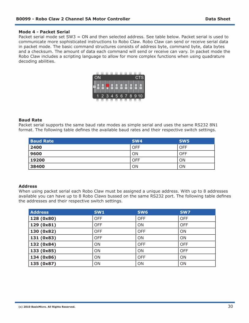
Mode 4 - Packet SerialPacketserialmodesetSW3=ONandthenselectedaddress.Seetablebelow.PacketserialisusedtocommunicatemoresophisticatedinstructionstoRoboClaw.RoboClawcansendorreceiveserialdatainpacketmode.Thebasiccommandstructuresconsistsofaddressbyte,commandbyte,databytesandachecksum.Theamountofdataeachcommandwillsendorreceivecanvary.InpacketmodetheRoboClawincludesascriptinglanguagetoallowformorecomplexfunctionswhenusingquadraturedecodingabilities.
Baud RatePacketserialsupportsthesamebaudratemodesassimpleserialandusesthesameRS2328N1format.Thefollowingtabledefinestheavailablebaudratesandtheirrespectiveswitchsettings.
Baud Rate SW4 SW52400 OFF OFF9600 ON OFF19200 OFF ON38400 ON ON
AddressWhenusingpacketserialeachRoboClawmustbeassignedauniqueaddress.Withupto8addressesavailableyoucanhaveupto8RoboClawsbussedonthesameRS232port.Thefollowingtabledefinestheaddressesandtheirrespectiveswitchsettings.
Address SW1 SW6 SW7128 (0x80) OFF OFF OFF129 (0x81) OFF ON OFF130 (0x82) OFF OFF ON131 (0x83) OFF ON ON132 (0x84) ON OFF OFF133 (0x85) ON ON OFF134 (0x86) ON OFF ON135 (0x87) ON ON ON
ON CTS
1 2 3 4 5 6 7 8 9 10

(c) 2010 BasicMicro. All Rights Reserved.
B0099 - Robo Claw 2 Channel 5A Motor Controller Data Sheet
31
CRC Checksum CalculationAllpacketserialcommandsusea7bitCRCchecksumtopreventcorruptcommandsfrombeingexecuted.SincetheRoboClawexpectsa7bitvaluethe8thbitismasked.ThebasicCRCchecksumiscalculatedasfollows:
Address+Command+Data=Checksum
Tomaskthe8thbityouusecanasimplemathexpressioncalledANDasshownbelow:
Serout P15, i19200, [128, 0, 127, (255 & 0X7F)]
Thehexadecimalvalue0X7Fisusedtomaskthe8thbit.Youcanalsouseabinaryvalueof01111111asshownbelow:
Serout P15, i19200, [128, 0, 127, (255 & %01111111)]
(c) 2010 BasicMicro. All Rights Reserved.
B0099 - Robo Claw 2 Channel 5A Motor Controller Data Sheet
32
Commands 0 - 7 Standard CommandsThefollowingcommandsarethestandardsetofcommandsusedwithpacketmode.Thecommandsyntaxisthesameforcommands0to7:
Address, Command, ByteValue, CRC
0 - Drive Forward M1Drivemotor1forward.Validdatarangeis0-127.Avalueof127=fullspeedforward,64=abouthalfspeedforwardand0=fullstop.ExamplewithRoboClawaddresssetto128:
Serout P15, i19200, [128, 0, 127, (255 & 0X7F)] ;M1 full speed forward
1 - Drive Backwards M1Drivemotor1backwards.Validdatarangeis0-127.Avalueof127fullspeedbackwards,64=abouthalfspeedbackwardand0=fullstop.ExamplewithRoboClawaddresssetto128:
Serout P15, i19200, [128, 1, 127, (256 & 0X7F)] ;M1 full speed forward
2 - Set Minimum Main Voltage Setsmainbattery(B-/B+)minimumvoltagelevel.IfthebatteryvoltagesdropsbelowthesetvoltagelevelRoboClawwillshutdown.Thevalueisclearedatstartupandmustsetaftereachpowerup.Thevoltageissetin.2voltincrements.Avalueof0setstheminimumvalueallowedwhichis6V.Thevaliddatarangeis0-120(6V-30V).Theformulaforcalculatingthevoltageis:(DesiredVolts-6)x5=Value.Examplesofvalidvaluesare6V=0,8V=10and11V=25.ExamplewithRoboClawaddresssetto128:
Serout P15, i19200, [128, 2, 25, (165 & 0X7F)]
3 - Set Maximum Main VoltageSetsmainbattery(B-/B+)maximumvoltagelevel.Thevaliddatarangeis0-154(0V-30V).Ifyouareusingabatteryofanytypeyoucanignorethissetting.Duringregenerativebreakingabackvoltageisappliedtochargethebattery.WhenusinganATXtypepowersupplyifitsensesanythingover16Vitwillshutdown.Bysettingthemaximumvoltagelevel,RoboClawbeforeexceedingitwillgointohardbreakingmodeuntilthevoltagedropsbelowthemaximumvalueset.Theformulaforcalculatingthevoltageis:DesiredVoltsx5.12=Value.Examplesofvalidvaluesare12V=62,16V=82and24V=123.ExamplewithRoboClawaddresssetto128:
Serout P15, i19200, [128, 3, 82, (213 & 0X7F)]
4 - Drive Forward M2Drivemotor2forward.Validdatarangeis0-127.Avalueof127fullspeedforward,64=abouthalfspeedforwardand0=fullstop.ExamplewithRoboClawaddresssetto128:
Serout P15, i19200, [128, 4, 127, (259 & 0X7F)] ;M2 full speed forward

(c) 2010 BasicMicro. All Rights Reserved.
B0099 - Robo Claw 2 Channel 5A Motor Controller Data Sheet
33
5 - Drive Backwards M2Drivemotor2backwards.Validdatarangeis0-127.Avalueof127fullspeedbackwards,64=abouthalfspeedbackwardand0=fullstop.ExamplewithRoboClawaddresssetto128:
Serout P15, i19200, [128, 5, 127, (260 & 0X7F)] ;M2 full speed forward
6 - Drive M1 (7 Bit)Drivemotor1forwardandreverse.Validdatarangeis0-127.Avalueof0=fullspeedreverse,64=stopand127=fullspeedforward.ExamplewithRoboClawaddresssetto128:
Serout P15, i19200, [128, 6, 96, (230 & 0X7F)] ;M1 half speed forward
7 - Drive M2 (7 Bit)Drivemotor2forwardandreverse.Validdatarangeis0-127.Avalueof0=fullspeedreverse,64=stopand127=fullspeedforward.ExamplewithRoboClawaddresssetto128:
Serout P15, i19200, [128, 7, 32, (167 & 0X7F)] ;M2 half speed reverse

(c) 2010 BasicMicro. All Rights Reserved.
B0099 - Robo Claw 2 Channel 5A Motor Controller Data Sheet
34
Commands 8 - 13 Mix Mode CommandsThefollowingcommandsaremixmodecommandsandusedtocontrolspeedandturn.Beforeacommandisexecutedvaliddriveandturndataisrequired.Youonlyneedtosendbothdatapacketsonce.AfterreceivingbothvaliddriveandturndataRoboClawwillbegintooperate.Atthispointyouonlyneedtoupdateturnordrivedata.
8 - Drive ForwardDriveforwardinmixmode.Validdatarangeis0-127.Avalueof0=fullstopand127=fullforward.ExamplewithRoboClawaddresssetto128:
Serout P15, i19200, [128, 8, 127, (263 & 0x7F)] ;full speed forward
9 - Drive BackwardsDrivebackwardsinmixmode.Validdatarangeis0-127.Avalueof0=fullstopand127=fullreverse.ExamplewithRoboClawaddresssetto128:
Serout P15, i19200, [128, 9, 127, (264 & 0x7F)] ;full speed reverse
10 - Turn rightTurnrightinmixmode.Validdatarangeis0-127.Avalueof0=stopturnand127=fullspeedturn.ExamplewithRoboClawaddresssetto128:
Serout P15, i19200, [128, 10, 127, (265 & 0x7F1)] ;full speed right turn
11 - Turn leftTurnleftinmixmode.Validdatarangeis0-127.Avalueof0=stopturnand127=fullspeedturn.ExamplewithRoboClawaddresssetto128:
Serout P15, i19200, [128, 11, 127, (266 & 0x7F)] ;full speed left turn
12 - Drive Forward or Backward (7 Bit)Driveforwardorbackwards.Validdatarangeis0-127.Avalueof0=fullbackward,64=stopand127=fullforward.ExamplewithRoboClawaddresssetto128:
Serout P15, i19200, [128, 12, 96, (236 & 0x7F)] ;medium speed forward
13 - Turn Left or Right (7 Bit)Turnleftorright.Validdatarangeis0-127.Avalueof0=fullleft,0=stopturnand127=fullright.ExamplewithRoboClawaddresssetto128:
Serout P15, i19200, [128, 13, 0, (141 & 0x7F)] ;full speed turn left

(c) 2010 BasicMicro. All Rights Reserved.
B0099 - Robo Claw 2 Channel 5A Motor Controller Data Sheet
35
R7
R5
SW1
S1S2S3+5V
R26
R24R25R4
U4
C3
LB+
Sta
tus2
Sta
tus1
2 | 1
- + B A
VD
3
Reset
Power Sel
0503
1
Err
orR
3
LB
C4
M1A M1B B+ B- M2B M2ABasicmicro.com (c) 2009
C5 O
NC
TS
12
34
56
78
910
Y1
ON
CTS
12
34
56
78
910
Packet Serial WiringInpacketmodetheRoboClawcantransmitandreceiveserialdata.SinceRoboClawistransmittingdataitisagoodideatouseaprocessorwithahardwareserialportliketheBasicATOMPro.
DC Motor 1 DC Motor 2
Power Switch
12VDC Battery
BatterySOUTSINATNVSSP0P1P2P3P4P5P6P7P16P17
VINVSSRESVCCP15P14P13P12P11P10P9P8P19P18
(c) 2010 BasicMicro. All Rights Reserved.
B0099 - Robo Claw 2 Channel 5A Motor Controller Data Sheet
36
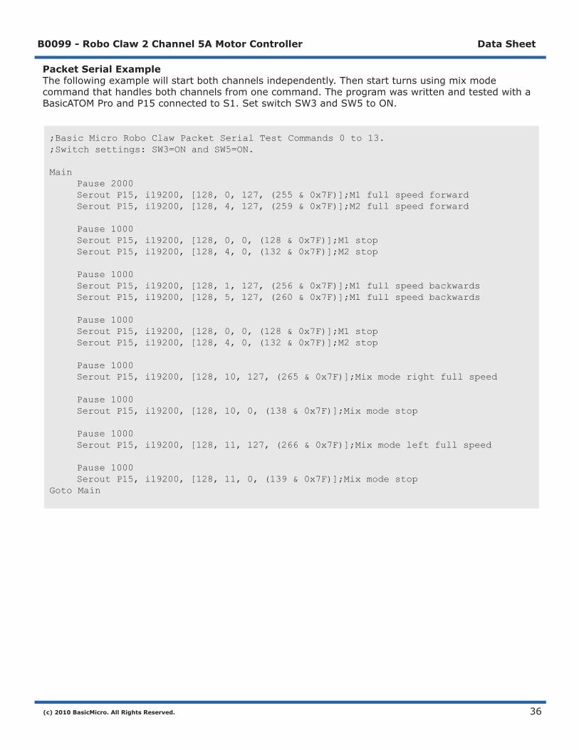
Packet Serial ExampleThefollowingexamplewillstartbothchannelsindependently.Thenstartturnsusingmixmodecommandthathandlesbothchannelsfromonecommand.TheprogramwaswrittenandtestedwithaBasicATOMProandP15connectedtoS1.SetswitchSW3andSW5toON.
;Basic Micro Robo Claw Packet Serial Test Commands 0 to 13. ;Switch settings: SW3=ON and SW5=ON.
Main Pause 2000 Serout P15, i19200, [128, 0, 127, (255 & 0x7F)];M1 full speed forward Serout P15, i19200, [128, 4, 127, (259 & 0x7F)];M2 full speed forward Pause 1000 Serout P15, i19200, [128, 0, 0, (128 & 0x7F)];M1 stop Serout P15, i19200, [128, 4, 0, (132 & 0x7F)];M2 stop Pause 1000 Serout P15, i19200, [128, 1, 127, (256 & 0x7F)];M1 full speed backwards Serout P15, i19200, [128, 5, 127, (260 & 0x7F)];M1 full speed backwards Pause 1000 Serout P15, i19200, [128, 0, 0, (128 & 0x7F)];M1 stop Serout P15, i19200, [128, 4, 0, (132 & 0x7F)];M2 stop Pause 1000 Serout P15, i19200, [128, 10, 127, (265 & 0x7F)];Mix mode right full speed Pause 1000 Serout P15, i19200, [128, 10, 0, (138 & 0x7F)];Mix mode stop Pause 1000 Serout P15, i19200, [128, 11, 127, (266 & 0x7F)];Mix mode left full speed Pause 1000 Serout P15, i19200, [128, 11, 0, (139 & 0x7F)];Mix mode stopGoto Main
(c) 2010 BasicMicro. All Rights Reserved.
B0099 - Robo Claw 2 Channel 5A Motor Controller Data Sheet
37
BatteryandVersionInformation
(c) 2010 BasicMicro. All Rights Reserved.
B0099 - Robo Claw 2 Channel 5A Motor Controller Data Sheet
38
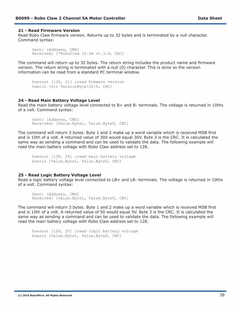
21 - Read Firmware VersionReadRoboClawfirmwareversion.Returnsupto32bytesandisterminatedbyanullcharacter.Commandsyntax:
Sent: [Address, CMD] Received: [“RoboClaw 10.2A v1.3.9, CRC]
Thecommandwillreturnupto32bytes.Thereturnstringincludestheproductnameandfirmwareversion.Thereturnstringisterminatedwithanull(0)character.ThisisdonesotheversioninformationcanbereadfromastandardPCterminalwindow.
hserout[128,21];readfirmwareversion hserin [Str VersionByte\32\0, CRC]
24 - Read Main Battery Voltage LevelReadthemainbatteryvoltagelevelconnectedtoB+andB-terminals.Thevoltageisreturnedin10thsofavolt.Commandsyntax:
Sent: [Address, CMD] Received: [Value.Byte1, Value.Byte0, CRC]
Thecommandwillreturn3bytes.Byte1and2makeupawordvariablewhichisreceivedMSBfirstandis10thofavolt.Areturnedvalueof300wouldequal30V.Byte3istheCRC.Itiscalculatedthesamewayassendingacommandandcanbeusedtovalidatethedata.ThefollowingexamplewillreadthemainbatteryvoltagewithRoboClawaddresssetto128.
hserout [128, 24] ;read main battery voltage hserin [Value.Byte1, Value.Byte0, CRC]
25 - Read Logic Battery Voltage LevelReadalogicbatteryvoltagelevelconnectedtoLB+andLB-terminals.Thevoltageisreturnedin10thsofavolt.Commandsyntax:
Sent: [Address, CMD] Received: [Value.Byte1, Value.Byte0, CRC]
Thecommandwillreturn3bytes.Byte1and2makeupawordvariablewhichisreceivedMSBfirstandis10thofavolt.Areturnedvalueof50wouldequal5V.Byte3istheCRC.Itiscalculatedthesamewayassendingacommandandcanbeusedtovalidatethedata.ThefollowingexamplewillreadthemainbatteryvoltagewithRoboClawaddresssetto128.
hserout [128, 25] ;read logic battery voltage hserin [Value.Byte1, Value.Byte0, CRC]

(c) 2010 BasicMicro. All Rights Reserved.
B0099 - Robo Claw 2 Channel 5A Motor Controller Data Sheet
39
26 - Set Minimum Logic Voltage LevelSetslogicinput(LB-/LB+)minimumvoltagelevel.IfthebatteryvoltagesdropsbelowthesetvoltagelevelRoboClawwillshutdown.Thevalueisclearedatstartupandmustsetaftereachpowerup.Thevoltageissetin.2voltincrements.Avalueof0setstheminimumvalueallowedwhichis3V.Thevaliddatarangeis0-120(6V-28V).Theformulaforcalculatingthevoltageis:(DesiredVolts-6)x5=Value.Examplesofvalidvaluesare3V=0,8V=10and11V=25.RoboClawexamplewithaddresssetto128:
hserout [128, 26, 0, (154 & 0X7F)]
27 - Set Maximum Logic Voltage LevelSetslogicinput(LB-/LB+)maximumvoltagelevel.Thevaliddatarangeis0-144(0V-28V).BysettingthemaximumvoltagelevelRoboClawwillgointoshutdownandrequiresahardresettorecovers.Theformulaforcalculatingthevoltageis:DesiredVoltsx5.12=Value.Examplesofvalidvaluesare12V=62,16V=82and24V=123.RoboClawexamplewithaddresssetto128:
hserout [128, 27, 82, (213 & 0X7F)]
Main Battery Voltage LevelsThemainbatterylevelsaresetinasimilarwayasthelogicbattery.Seecommand2and3fordetails.
(c) 2010 BasicMicro. All Rights Reserved.
B0099 - Robo Claw 2 Channel 5A Motor Controller Data Sheet
40
QuadratureDecoding

(c) 2010 BasicMicro. All Rights Reserved.
B0099 - Robo Claw 2 Channel 5A Motor Controller Data Sheet
41
Quadrature DecodingHandlingthequadratureencodersisdoneusingpacketserial.Alltheswitchsettingsstillapplyintoenablingpacketserialandsettingthedesiredbaudrates.SeeMode-PacketSerial.ThefollowingcommandsdealspecificallywiththedualquadraturedecodersbuiltintoRoboClaw.
CRC Checksum CalculationAllpacketserialcommandsusea7bitCRCchecksumtopreventcorruptcommandsfrombeingexecuted.SincetheRoboClawexpectsa7bitvaluethe8thbitismasked.ThebasicCRCchecksumiscalculatedasfollows:
Address+Command+Data=Checksum
Tomaskthe8thbityouusecanasimplemathexpressioncalledANDasshownbelow:
Serout P15, i19200, [128, 0, 127, (255 & 0X7F)]
Thehexadecimalvalue0X7Fisusedtomaskthe8thbit.Youcanalsouseabinaryvalueof01111111asshownbelow:
Serout P15, i19200, [128, 0, 127, (255 & %01111111)]
(c) 2010 BasicMicro. All Rights Reserved.
B0099 - Robo Claw 2 Channel 5A Motor Controller Data Sheet
42
R7R
5
SW
1
S1
S2
S3
R26
R24
R25
U4
C3
LB+Status2
2 | 1-+BA
VD3 Reset
Pow
er S
el
0503
1
Error R3
LB
C4
M1A
M1B
B+
B-
M2B
M2A
Basicm
icro.com (c) 2009
C5ON CTS
1 2 3 4 5 6 7 8 9 10
Y1 ON CTS
1 2 3 4 5 6 7 8 9 10
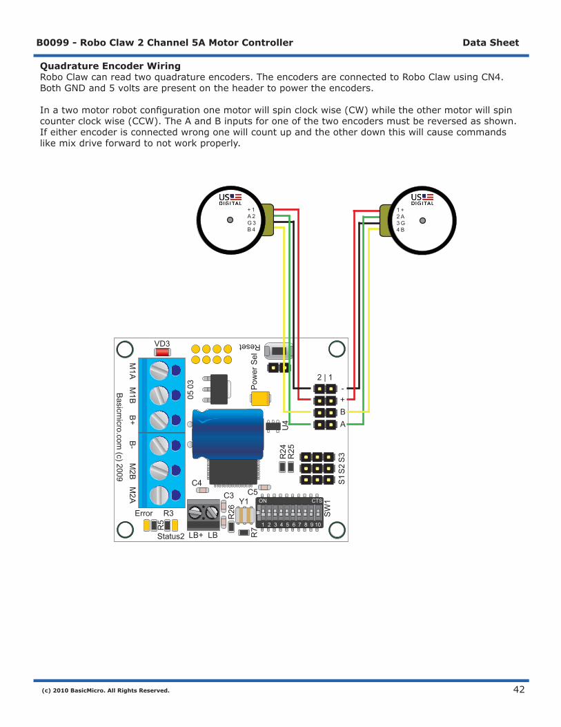
Quadrature Encoder WiringRoboClawcanreadtwoquadratureencoders.TheencodersareconnectedtoRoboClawusingCN4.BothGNDand5voltsarepresentontheheadertopowertheencoders.
Inatwomotorrobotconfigurationonemotorwillspinclockwise(CW)whiletheothermotorwillspincounterclockwise(CCW).TheAandBinputsforoneofthetwoencodersmustbereversedasshown.Ifeitherencoderisconnectedwrongonewillcountupandtheotherdownthiswillcausecommandslikemixdriveforwardtonotworkproperly.
+ 1A 2G 3B 4
1 +2 A3 G4 B
(c) 2010 BasicMicro. All Rights Reserved.
B0099 - Robo Claw 2 Channel 5A Motor Controller Data Sheet
43
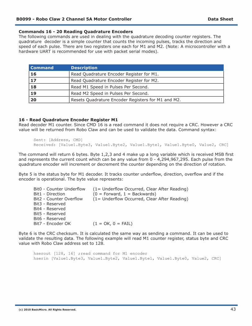
Commands 16 - 20 Reading Quadrature EncodersThefollowingcommandsareusedindealingwiththequadraturedecodingcounterregisters.Thequadraturedecoderisasimplecounterthatcountstheincomingpulses,tracksthedirectionandspeedofeachpulse.TherearetworegistersoneeachforM1andM2.(Note:AmicrocontrollerwithahardwareUARTisrecommendedforusewithpacketserialmodes).
Command Description16 ReadQuadratureEncoderRegisterforM1.17 ReadQuadratureEncoderRegisterforM2.18 ReadM1SpeedinPulsesPerSecond.19 ReadM2SpeedinPulsesPerSecond.20 ResetsQuadratureEncoderRegistersforM1andM2.
16 - Read Quadrature Encoder Register M1ReaddecoderM1counter.SinceCMD16isareadcommanditdoesnotrequireaCRC.HoweveraCRCvaluewillbereturnedfromRoboClawandcanbeusedtovalidatethedata.Commandsyntax:
Sent: [Address, CMD] Received: [Value1.Byte3, Value1.Byte2, Value1.Byte1, Value1.Byte0, Value2, CRC]
Thecommandwillreturn6bytes.Byte1,2,3and4makeupalongvariablewhichisreceivedMSBfirstandrepresentsthecurrentcountwhichcanbeanyvaluefrom0-4,294,967,295.Eachpulsefromthequadratureencoderwillincrementordecrementthecounterdependingonthedirectionofrotation.
Byte5isthestatusbyteforM1decoder.Ittrackscounterunderflow,direction,overflowandiftheencoderisoperational.Thebytevaluerepresents:
Bit0-CounterUnderflow (1=UnderflowOccurred,ClearAfterReading) Bit1-Direction (0=Forward,1=Backwards) Bit2-CounterOverflow (1=UnderflowOccurred,ClearAfterReading) Bit3-Reserved Bit4-Reserved Bit5-Reserved Bit6-Reserved Bit7-EncoderOK (1=OK,0=FAIL)
Byte6istheCRCchecksum.Itiscalculatedthesamewayassendingacommand.Itcanbeusedtovalidatetheresultingdata.ThefollowingexamplewillreadM1counterregister,statusbyteandCRCvaluewithRoboClawaddresssetto128.
hserout [128, 16] ;read command for M1 encoder hserin [Value1.Byte3, Value1.Byte2, Value1.Byte1, Value1.Byte0, Value2, CRC]

(c) 2010 BasicMicro. All Rights Reserved.
B0099 - Robo Claw 2 Channel 5A Motor Controller Data Sheet
44
17 - Read Quadrature Encoder Register M2ReaddecoderM2counter.SinceCMD16isareadcommanditdoesnotrequireaCRC.HoweveraCRCvaluewillbereturnedfromRoboClawandcanbeusedtovalidatethedata.Commandsyntax:
Sent: [Address, CMD] Received: [Value1.Byte3, Value1.Byte2, Value1.Byte1, Value1.Byte0, Value2, CRC]
Thecommandwillreturn6bytes.Byte1,2,3and4makeupalongvariablewhichisreceivedMSBfirstandrepresentsthecurrentcountwhichcanbeanyvaluefrom0-4,294,967,295.Eachpulsefromthequadratureencoderwillincrementordecrementthecounterdependingonthedirectionofrotation.
Byte5isthestatusbyteforM1decoder.Ittrackscounterunderflow,direction,overflowandiftheencoderisoperational.Thebytevaluerepresents:
Bit0-CounterUnderflow(1=UnderflowOccurred,ClearAfterReading) Bit1-Direction(0=Forward,1=Backwards) Bit2-CounterOverflow(1=UnderflowOccurred,ClearAfterReading) Bit3-Reserved Bit4-Reserved Bit5-Reserved Bit6-Reserved Bit7-EncoderOK(1=OK,0=FAIL)
Byte6istheCRCchecksum.Itiscalculatedthesamewayassendingacommand.Itcanbeusedtovalidatetheresultingdata.ThefollowingexamplewillreadM1counterregister,statusbyteandCRCvaluewithRoboClawaddresssetto128.
hserout [128, 17] ;read command for M2 encoder hserin [Value1.Byte3, Value1.Byte2, Value1.Byte1, Value1.Byte0, Value2, CRC]
18 - Read Speed M1ReadM1counterspeed.Returnedvalueisinpulsespersecond.RoboClawkeepstrackofhowmanypulsesreceivedpersecondforbothdecoderchannels.SinceCMD18isareadcommanditdoesnotrequireaCRCtobesent.HoweveraCRCvaluewillbereturnedfromRoboClawandcanbeusedtovalidatethedata.Commandsyntax:
Sent: [Address, CMD] Received: [Value1.Byte3, Value1.Byte2, Value1.Byte1, Value1.Byte0, Value2, CRC]
Thecommandwillreturn6bytes.Byte1,2,3and4makeupalongvariablewhichisreceivedMSBfirstandisthecurrenttickspersecondwhichcanbeanyvaluefrom0-4,294,967,295.Byte5isthedirection(0–forward,1-backward).Byte6istheCRC.Itiscalculatedthesamewayassendingacommandandcanbeusedtovalidatethedata.ThefollowingexamplewillreadM1pulsepersecondanddirectionwithRoboClawaddresssetto128.
hserout [128, 18] ;read command for M1 encoder hserin [Value1.Byte3, Value1.Byte2, Value1.Byte1, Value1.Byte0, Value2, CRC]

(c) 2010 BasicMicro. All Rights Reserved.
B0099 - Robo Claw 2 Channel 5A Motor Controller Data Sheet
45
19 - Read Speed M2ReadM2counterspeed.Returnedvalueisinpulsespersecond.RoboClawkeepstrackofhowmanypulsesreceivedpersecondforbothdecoderchannels.SinceCMD19isareadcommanditdoesnotrequireaCRCtobesent.HoweveraCRCvaluewillbereturnedfromRoboClawandcanbeusedtovalidatethedata.Commandsyntax:
Sent: [Address, CMD] Received: [Value1.Byte3, Value1.Byte2, Value1.Byte1, Value1.Byte0, Value2, CRC]
Thecommandwillreturn6bytes.Byte1,2,3and4makeupalongvariablewhichisreceivedMSBfirstandisthecurrenttickspersecondwhichcanbeanyvaluefrom0-4,294,967,295.Byte5isthedirection(0–forward,1-backward).Byte6istheCRC.Itiscalculatedthesamewayassendingacommandandcanbeusedtovalidatethedata.ThefollowingexamplewillreadM2pulsepersecondanddirectionwithRoboClawaddresssetto128.
hserout [128, 19] ;read command for M2 encoder hserin [Value1.Byte3, Value1.Byte2, Value1.Byte1, Value1.Byte0, Value2, CRC]
20 - Reset Quadrature Encoder CountersWillresetbothquadraturedecodercounterstozero.SinceCMD20isawritecommandaCRCvalueisrequired.Commandsyntaxandexample:
hserout [128, 20, (148 & %01111111)]; resets encoder registers
(c) 2010 BasicMicro. All Rights Reserved.
B0099 - Robo Claw 2 Channel 5A Motor Controller Data Sheet
46
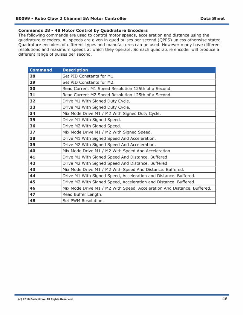
Commands 28 - 48 Motor Control by Quadrature EncodersThefollowingcommandsareusedtocontrolmotorspeeds,accelerationanddistanceusingthequadratureencoders.Allspeedsaregiveninquadpulsespersecond(QPPS)unlessotherwisestated.Quadratureencodersofdifferenttypesandmanufacturescanbeused.Howevermanyhavedifferentresolutionsandmaximumspeedsatwhichtheyoperate.Soeachquadratureencoderwillproduceadifferentrangeofpulsespersecond.
Command Description28 SetPIDConstantsforM1.29 SetPIDConstantsforM2.30 ReadCurrentM1SpeedResolution125thofaSecond.31 ReadCurrentM2SpeedResolution125thofaSecond.32 DriveM1WithSignedDutyCycle.33 DriveM2WithSignedDutyCycle.34 MixModeDriveM1/M2WithSignedDutyCycle.35 DriveM1WithSignedSpeed.36 DriveM2WithSignedSpeed.37 MixModeDriveM1/M2WithSignedSpeed.38 DriveM1WithSignedSpeedAndAcceleration.39 DriveM2WithSignedSpeedAndAcceleration.40 MixModeDriveM1/M2WithSpeedAndAcceleration.41 DriveM1WithSignedSpeedAndDistance.Buffered.42 DriveM2WithSignedSpeedAndDistance.Buffered.43 MixModeDriveM1/M2WithSpeedAndDistance.Buffered.44 DriveM1WithSignedSpeed,AccelerationandDistance.Buffered.45 DriveM2WithSignedSpeed,AccelerationandDistance.Buffered.46 MixModeDriveM1/M2WithSpeed,AccelerationAndDistance.Buffered.47 ReadBufferLength.48 SetPWMResolution.
(c) 2010 BasicMicro. All Rights Reserved.
B0099 - Robo Claw 2 Channel 5A Motor Controller Data Sheet
47
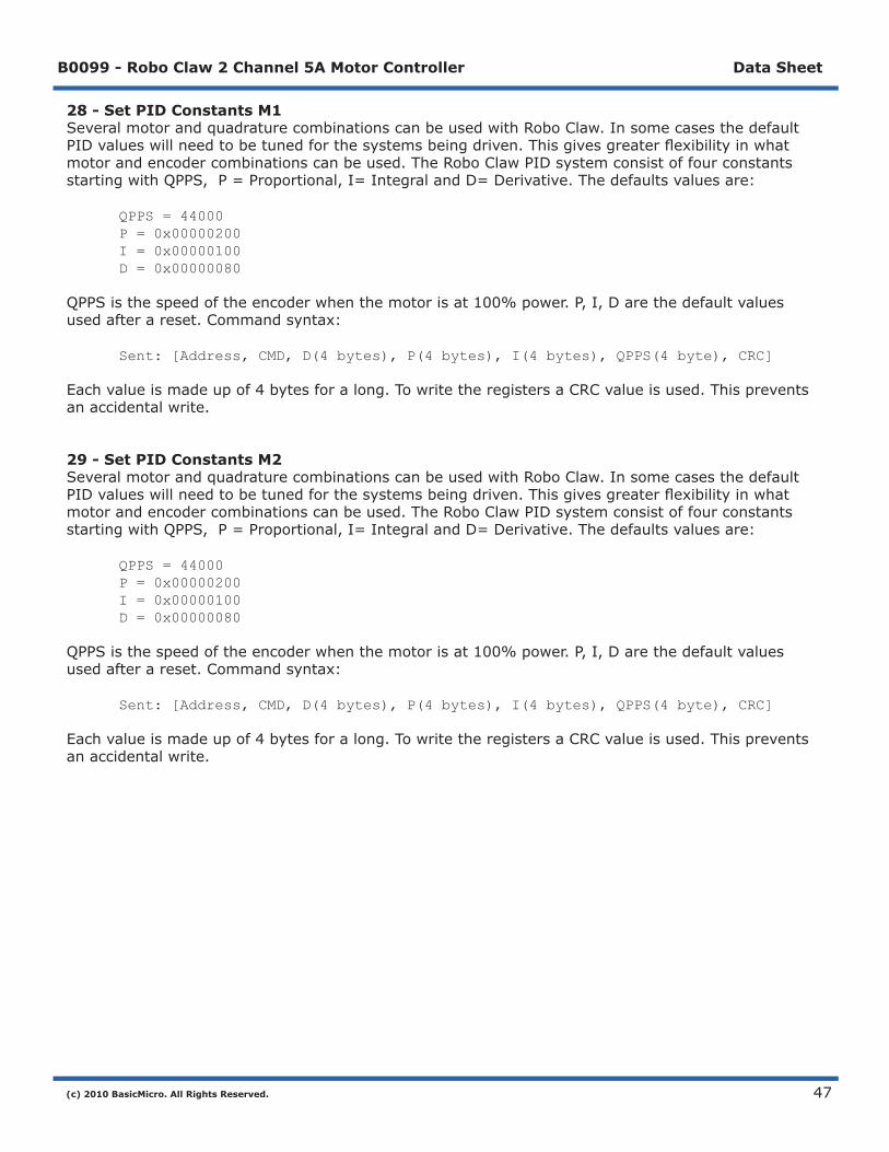
28 - Set PID Constants M1SeveralmotorandquadraturecombinationscanbeusedwithRoboClaw.InsomecasesthedefaultPIDvalueswillneedtobetunedforthesystemsbeingdriven.Thisgivesgreaterflexibilityinwhatmotorandencodercombinationscanbeused.TheRoboClawPIDsystemconsistoffourconstantsstartingwithQPPS,P=Proportional,I=IntegralandD=Derivative.Thedefaultsvaluesare:
QPPS = 44000 P = 0x00000200 I = 0x00000100 D = 0x00000080
QPPSisthespeedoftheencoderwhenthemotorisat100%power.P,I,Darethedefaultvaluesusedafterareset.Commandsyntax:
Sent: [Address, CMD, D(4 bytes), P(4 bytes), I(4 bytes), QPPS(4 byte), CRC]
Eachvalueismadeupof4bytesforalong.TowritetheregistersaCRCvalueisused.Thispreventsanaccidentalwrite.
29 - Set PID Constants M2SeveralmotorandquadraturecombinationscanbeusedwithRoboClaw.InsomecasesthedefaultPIDvalueswillneedtobetunedforthesystemsbeingdriven.Thisgivesgreaterflexibilityinwhatmotorandencodercombinationscanbeused.TheRoboClawPIDsystemconsistoffourconstantsstartingwithQPPS,P=Proportional,I=IntegralandD=Derivative.Thedefaultsvaluesare:
QPPS = 44000 P = 0x00000200 I = 0x00000100 D = 0x00000080
QPPSisthespeedoftheencoderwhenthemotorisat100%power.P,I,Darethedefaultvaluesusedafterareset.Commandsyntax:
Sent: [Address, CMD, D(4 bytes), P(4 bytes), I(4 bytes), QPPS(4 byte), CRC]
Eachvalueismadeupof4bytesforalong.TowritetheregistersaCRCvalueisused.Thispreventsanaccidentalwrite.
(c) 2010 BasicMicro. All Rights Reserved.
B0099 - Robo Claw 2 Channel 5A Motor Controller Data Sheet
48
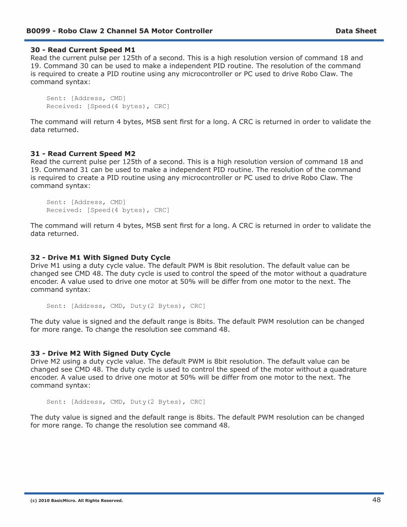
30 - Read Current Speed M1Readthecurrentpulseper125thofasecond.Thisisahighresolutionversionofcommand18and19.Command30canbeusedtomakeaindependentPIDroutine.TheresolutionofthecommandisrequiredtocreateaPIDroutineusinganymicrocontrollerorPCusedtodriveRoboClaw.Thecommandsyntax:
Sent: [Address, CMD]Received: [Speed(4 bytes), CRC]
Thecommandwillreturn4bytes,MSBsentfirstforalong.ACRCisreturnedinordertovalidatethedatareturned.
31 - Read Current Speed M2Readthecurrentpulseper125thofasecond.Thisisahighresolutionversionofcommand18and19.Command31canbeusedtomakeaindependentPIDroutine.TheresolutionofthecommandisrequiredtocreateaPIDroutineusinganymicrocontrollerorPCusedtodriveRoboClaw.Thecommandsyntax:
Sent: [Address, CMD]Received: [Speed(4 bytes), CRC]
Thecommandwillreturn4bytes,MSBsentfirstforalong.ACRCisreturnedinordertovalidatethedatareturned.
32 - Drive M1 With Signed Duty CycleDriveM1usingadutycyclevalue.ThedefaultPWMis8bitresolution.ThedefaultvaluecanbechangedseeCMD48.Thedutycycleisusedtocontrolthespeedofthemotorwithoutaquadratureencoder.Avalueusedtodriveonemotorat50%willbedifferfromonemotortothenext.Thecommandsyntax:
Sent: [Address, CMD, Duty(2 Bytes), CRC]
Thedutyvalueissignedandthedefaultrangeis8bits.ThedefaultPWMresolutioncanbechangedformorerange.Tochangetheresolutionseecommand48.
33 - Drive M2 With Signed Duty CycleDriveM2usingadutycyclevalue.ThedefaultPWMis8bitresolution.ThedefaultvaluecanbechangedseeCMD48.Thedutycycleisusedtocontrolthespeedofthemotorwithoutaquadratureencoder.Avalueusedtodriveonemotorat50%willbedifferfromonemotortothenext.Thecommandsyntax:
Sent: [Address, CMD, Duty(2 Bytes), CRC]
Thedutyvalueissignedandthedefaultrangeis8bits.ThedefaultPWMresolutioncanbechangedformorerange.Tochangetheresolutionseecommand48.

(c) 2010 BasicMicro. All Rights Reserved.
B0099 - Robo Claw 2 Channel 5A Motor Controller Data Sheet
49
34 - Mix Mode Drive M1 / M2 With Signed Duty CycleDrivebothM1andM2usingadutycyclevalue.ThedefaultPWMis8bitresolution.ThedefaultvaluecanbechangedseeCMD48.Thedutycycleisusedtocontrolthespeedofthemotorwithoutaquadratureencoder.Avalueusedtodriveonemotorat50%willbedifferfromonemotortothenext.Thecommandsyntax:
Sent: [Address, CMD, DutyM1(2 Bytes), DutyM2(2 Bytes), CRC]
Thedutyvalueissignedandthedefaultrangeis8bits.ThedefaultPWMresolutioncanbechangedformorerange.Tochangetheresolutionseecommand48.
35 - Drive M1 With Signed SpeedDriveM1usingaspeedvalue.Thesignindicateswhichdirectionthemotorwillturn.Thiscommandisusedtodrivethemotorbyquadpulsespersecond.Differentquadratureencoderswillhavedifferentratesatwhichtheygeneratetheincomingpulses.Thevaluesusedwilldifferfromoneencodertoanother.Onceavalueissentthemotorwillbegintoaccelerateasfastaspossibleuntilthedefinedrateisreached.Thecommandsyntax:
Sent: [Address, CMD, Qspeed(4 Bytes), CRC]
4Bytes(long)areusedtoexpressthepulsespersecond.Quadratureencoderssend4pulsespertick.So1000tickswouldbecountedas4000pulses.
36 - Drive M2 With Signed SpeedDriveM2withaspeedvalue.Thesignindicateswhichdirectionthemotorwillturn.Thiscommandisusedtodrivethemotorbyquadpulsespersecond.Differentquadratureencoderswillhavedifferentratesatwhichtheygeneratetheincomingpulses.Thevaluesusedwilldifferfromoneencodertoanother.Onceavalueissent,themotorwillbegintoaccelerateasfastaspossibleuntiltheratedefinedisreached.Thecommandsyntax:
Sent: [Address, CMD, Qspeed(4 Bytes), CRC]
4Bytes(long)areusedtoexpressedthepulsespersecond.Quadratureencoderssend4pulsespertick.So1000tickswouldbecountedas4000pulses.

(c) 2010 BasicMicro. All Rights Reserved.
B0099 - Robo Claw 2 Channel 5A Motor Controller Data Sheet
50
37 - Mix Mode Drive M1 / M2 With Signed SpeedDriveM1andM2inthesamecommandusingasignedspeedvalue.Thesignindicateswhichdirectionthemotorwillturn.Thiscommandisusedtodrivebothmotorsbyquadpulsespersecond.Differentquadratureencoderswillhavedifferentratesatwhichtheygeneratetheincomingpulses.Thevaluesusedwilldifferfromoneencodertoanother.Onceavalueissentthemotorwillbegintoaccelerateasfastaspossibleuntiltheratedefinedisreached.Thecommandsyntax:
Sent: [Address, CMD, QspeedM1(4 Bytes), QspeedM2(4 Bytes), CRC]
4Bytes(long)areusedtoexpressthepulsespersecond.Quadratureencoderssend4pulsespertick.So1000tickswouldbecountedas4000pulses.
38 - Drive M1 With Signed Speed And AccelerationDriveM1withasignedspeedandaccelerationvalue.Thesignindicateswhichdirectionthemotorwillrun.Theaccelerationvaluesarenotsigned.Thiscommandisusedtodrivethemotorbyquadpulsespersecondandusinganaccelerationvalueforramping.Differentquadratureencoderswillhavedifferentratesatwhichtheygeneratetheincomingpulses.Thevaluesusedwilldifferfromoneencodertoanother.Onceavalueissentthemotorwillbegintoaccelerateincrementallyuntiltheratedefinedisreached.Thecommandsyntax:
Sent: [Address, CMD, Accel(4 Bytes), Qspeed(4 Bytes), CRC]
4Bytes(long)areusedtoexpressthepulsespersecond.Quadratureencoderssend4pulsespertick.So1000tickswouldbecountedas4000pulses.Theaccelerationismeasuredinspeedpersecond.Anaccelerationvalueof12,000QPPSwithaspeedof12,000QPPSwouldaccelerateamotorfrom0to12,000QPPSin1second.Anotherexamplewouldbeanaccelerationvalueof24,000QPPSandaspeedvalueof12,000QPPSwouldacceleratethemotorto12,000QPPSin0.5seconds.
39 - Drive M2 With Signed Speed And AccelerationDriveM2withasignedspeedandaccelerationvalue.Thesignindicateswhichdirectionthemotorwillrun.Theaccelerationvalueisnotsigned.Thiscommandisusedtodrivethemotorbyquadpulsespersecondandusinganaccelerationvalueforramping.Differentquadratureencoderswillhavedifferentratesatwhichtheygeneratetheincomingpulses.Thevaluesusedwilldifferfromoneencodertoanother.Onceavalueissentthemotorwillbegintoaccelerateincrementallyuntiltheratedefinedisreached.Thecommandsyntax:
Sent: [Address, CMD, Accel(4 Bytes), Qspeed(4 Bytes), CRC]
4Bytes(long)areusedtoexpressthepulsespersecond.Quadratureencoderssend4pulsespertick.So1000tickswouldbecountedas4000pulses.Theaccelerationismeasuredinspeedpersecond.Anaccelerationvalueof12,000QPPSwithaspeedof12,000QPPSwouldaccelerateamotorfrom0to12,000QPPSin1second.Anotherexamplewouldbeanaccelerationvalueof24,000QPPSandaspeedvalueof12,000QPPSwouldacceleratethemotorto12,000QPPSin0.5seconds.
(c) 2010 BasicMicro. All Rights Reserved.
B0099 - Robo Claw 2 Channel 5A Motor Controller Data Sheet
51
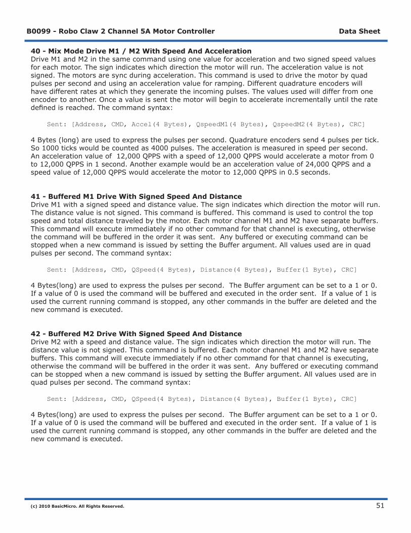
40 - Mix Mode Drive M1 / M2 With Speed And AccelerationDriveM1andM2inthesamecommandusingonevalueforaccelerationandtwosignedspeedvaluesforeachmotor.Thesignindicateswhichdirectionthemotorwillrun.Theaccelerationvalueisnotsigned.Themotorsaresyncduringacceleration.Thiscommandisusedtodrivethemotorbyquadpulsespersecondandusinganaccelerationvalueforramping.Differentquadratureencoderswillhavedifferentratesatwhichtheygeneratetheincomingpulses.Thevaluesusedwilldifferfromoneencodertoanother.Onceavalueissentthemotorwillbegintoaccelerateincrementallyuntiltheratedefinedisreached.Thecommandsyntax:
Sent: [Address, CMD, Accel(4 Bytes), QspeedM1(4 Bytes), QspeedM2(4 Bytes), CRC]
4Bytes(long)areusedtoexpressthepulsespersecond.Quadratureencoderssend4pulsespertick.So1000tickswouldbecountedas4000pulses.Theaccelerationismeasuredinspeedpersecond.Anaccelerationvalueof12,000QPPSwithaspeedof12,000QPPSwouldaccelerateamotorfrom0to12,000QPPSin1second.Anotherexamplewouldbeanaccelerationvalueof24,000QPPSandaspeedvalueof12,000QPPSwouldacceleratethemotorto12,000QPPSin0.5seconds.
41 - Buffered M1 Drive With Signed Speed And DistanceDriveM1withasignedspeedanddistancevalue.Thesignindicateswhichdirectionthemotorwillrun.Thedistancevalueisnotsigned.Thiscommandisbuffered.Thiscommandisusedtocontrolthetopspeedandtotaldistancetraveledbythemotor.EachmotorchannelM1andM2haveseparatebuffers.Thiscommandwillexecuteimmediatelyifnoothercommandforthatchannelisexecuting,otherwisethecommandwillbebufferedintheorderitwassent.AnybufferedorexecutingcommandcanbestoppedwhenanewcommandisissuedbysettingtheBufferargument.Allvaluesusedareinquadpulsespersecond.Thecommandsyntax:
Sent: [Address, CMD, QSpeed(4 Bytes), Distance(4 Bytes), Buffer(1 Byte), CRC]
4Bytes(long)areusedtoexpressthepulsespersecond.TheBufferargumentcanbesettoa1or0.Ifavalueof0isusedthecommandwillbebufferedandexecutedintheordersent.Ifavalueof1isusedthecurrentrunningcommandisstopped,anyothercommandsinthebufferaredeletedandthenewcommandisexecuted.
42 - Buffered M2 Drive With Signed Speed And DistanceDriveM2withaspeedanddistancevalue.Thesignindicateswhichdirectionthemotorwillrun.Thedistancevalueisnotsigned.Thiscommandisbuffered.EachmotorchannelM1andM2haveseparatebuffers.Thiscommandwillexecuteimmediatelyifnoothercommandforthatchannelisexecuting,otherwisethecommandwillbebufferedintheorderitwassent.AnybufferedorexecutingcommandcanbestoppedwhenanewcommandisissuedbysettingtheBufferargument.Allvaluesusedareinquadpulsespersecond.Thecommandsyntax:
Sent: [Address, CMD, QSpeed(4 Bytes), Distance(4 Bytes), Buffer(1 Byte), CRC]
4Bytes(long)areusedtoexpressthepulsespersecond.TheBufferargumentcanbesettoa1or0.Ifavalueof0isusedthecommandwillbebufferedandexecutedintheordersent.Ifavalueof1isusedthecurrentrunningcommandisstopped,anyothercommandsinthebufferaredeletedandthenewcommandisexecuted.

(c) 2010 BasicMicro. All Rights Reserved.
B0099 - Robo Claw 2 Channel 5A Motor Controller Data Sheet
52
43 - Buffered Mix Mode Drive M1 / M2 With Signed Speed And DistanceDriveM1andM2withaspeedanddistancevalue.Thesignindicateswhichdirectionthemotorwillrun.Thedistancevalueisnotsigned.Thiscommandisbuffered.EachmotorchannelM1andM2haveseparatebuffers.Thiscommandwillexecuteimmediatelyifnoothercommandforthatchannelisexecuting,otherwisethecommandwillbebufferedintheorderitwassent.AnybufferedorexecutingcommandcanbestoppedwhenanewcommandisissuedbysettingtheBufferargument.Allvaluesusedareinquadpulsespersecond.Thecommandsyntax:
Sent: [Address, CMD, QSpeedM1(4 Bytes), DistanceM1(4 Bytes), QSpeedM2(4 Bytes), DistanceM2(4 Bytes), Buffer(1 Byte), CRC]
4Bytes(long)areusedtoexpressthepulsespersecond.TheBufferargumentcanbesettoa1or0.Ifavalueof0isusedthecommandwillbebufferedandexecutedintheordersent.Ifavalueof1isusedthecurrentrunningcommandisstopped,anyothercommandsinthebufferaredeletedandthenewcommandisexecuted.
44 - Buffered M1 Drive With Signed Speed, Accel And DistanceDriveM1withaspeed,accelerationanddistancevalue.Thesignindicateswhichdirectionthemotorwillrun.Theaccelerationanddistancevaluesarenotsigned.Thiscommandisusedtocontrolthemotorstopspeed,totaldistancedtraveledandatwhatincrementalaccelerationvaluetouseuntilthetopspeedisreached.EachmotorchannelM1andM2haveseparatebuffers.Thiscommandwillexecuteimmediatelyifnoothercommandforthatchannelisexecuting,otherwisethecommandwillbebufferedintheorderitwassent.AnybufferedorexecutingcommandcanbestoppedwhenanewcommandisissuedbysettingtheBufferargument.Allvaluesusedareinquadpulsespersecond.Thecommandsyntax:
Sent: [Address, CMD, Accel(4 bytes), QSpeed(4 Bytes), Distance(4 Bytes), Buffer(1 Byte), CRC]
4Bytes(long)areusedtoexpressthepulsespersecond.TheBufferargumentcanbesettoa1or0.Ifavalueof0isusedthecommandwillbebufferedandexecutedintheordersent.Ifavalueof1isusedthecurrentrunningcommandisstopped,anyothercommandsinthebufferaredeletedandthenewcommandisexecuted.
45 - Buffered M2 Drive With Signed Speed, Accel And DistanceDriveM2withaspeed,accelerationanddistancevalue.Thesignindicateswhichdirectionthemotorwillrun.Theaccelerationanddistancevaluesarenotsigned.Thiscommandisusedtocontrolthemotorstopspeed,totaldistancedtraveledandatwhatincrementalaccelerationvaluetouseuntilthetopspeedisreached.EachmotorchannelM1andM2haveseparatebuffers.Thiscommandwillexecuteimmediatelyifnoothercommandforthatchannelisexecuting,otherwisethecommandwillbebufferedintheorderitwassent.AnybufferedorexecutingcommandcanbestoppedwhenanewcommandisissuedbysettingtheBufferargument.Allvaluesusedareinquadpulsespersecond.Thecommandsyntax:
Sent: [Address, CMD, Accel(4 bytes), QSpeed(4 Bytes), Distance(4 Bytes), Buffer(1 Byte), CRC]
4Bytes(long)areusedtoexpressthepulsespersecond.TheBufferargumentcanbesettoa1or0.Ifavalueof0isusedthecommandwillbebufferedandexecutedintheordersent.Ifavalueof1isusedthecurrentrunningcommandisstopped,anyothercommandsinthebufferaredeletedandthenewcommandisexecuted.
(c) 2010 BasicMicro. All Rights Reserved.
B0099 - Robo Claw 2 Channel 5A Motor Controller Data Sheet
53
46 - Buffered Mix Mode Drive M1 / M2 With Signed Speed, Accel And DistanceDriveM1andM2withaspeed,accelerationanddistancevalue.Thesignindicateswhichdirectionthemotorwillrun.Theaccelerationanddistancevaluesarenotsigned.Thiscommandisusedtocontrolbothmotorstopspeed,totaldistancedtraveledandatwhatincrementalaccelerationvaluetouseuntilthetopspeedisreached.EachmotorchannelM1andM2haveseparatebuffers.Thiscommandwillexecuteimmediatelyifnoothercommandforthatchannelisexecuting,otherwisethecommandwillbebufferedintheorderitwassent.AnybufferedorexecutingcommandcanbestoppedwhenanewcommandisissuedbysettingtheBufferargument.Allvaluesusedareinquadpulsespersecond.Thecommandsyntax:
Sent: [Address, CMD, Accel(4 Bytes), QSpeedM1(4 Bytes), DistanceM1(4 Bytes), QSpeedM2(4 bytes), DistanceM2(4 Bytes), Buffer(1 Byte), CRC]
4Bytes(long)areusedtoexpressthepulsespersecond.TheBufferargumentcanbesettoa1or0.Ifavalueof0isusedthecommandwillbebufferedandexecutedintheordersent.Ifavalueof1isusedthecurrentrunningcommandisstopped,anyothercommandsinthebufferaredeletedandthenewcommandisexecuted.
47 - Read Buffer LengthReadbothmotorM1andM2bufferlengths.Thiscommandcanbeusedtodeterminehowmanycommandsarewaitingtoexecute.
Sent: [Address, CMD]Received: [BufferM1(1 Bytes), BufferM2(1 Bytes), CRC]
Thereturnvaluesrepresenthowmanycommandsperbufferarewaitingtobeexecuted.Themaximumbuffersizepermotoris24commands.
(c) 2010 BasicMicro. All Rights Reserved.
B0099 - Robo Claw 2 Channel 5A Motor Controller Data Sheet
54
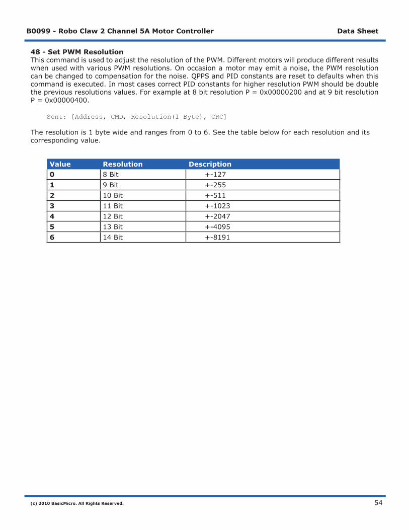
48 - Set PWM ResolutionThiscommandisusedtoadjusttheresolutionofthePWM.DifferentmotorswillproducedifferentresultswhenusedwithvariousPWMresolutions.Onoccasionamotormayemitanoise,thePWMresolutioncanbechangedtocompensationforthenoise.QPPSandPIDconstantsareresettodefaultswhenthiscommandisexecuted.InmostcasescorrectPIDconstantsforhigherresolutionPWMshouldbedoublethepreviousresolutionsvalues.Forexampleat8bitresolutionP=0x00000200andat9bitresolutionP=0x00000400.
Sent: [Address, CMD, Resolution(1 Byte), CRC]
Theresolutionis1bytewideandrangesfrom0to6.Seethetablebelowforeachresolutionanditscorrespondingvalue.
Value Resolution Description0 8Bit +-1271 9Bit +-2552 10Bit +-5113 11Bit +-10234 12Bit +-20475 13Bit +-40956 14Bit +-8191
(c) 2010 BasicMicro. All Rights Reserved.
B0099 - Robo Claw 2 Channel 5A Motor Controller Data Sheet
55
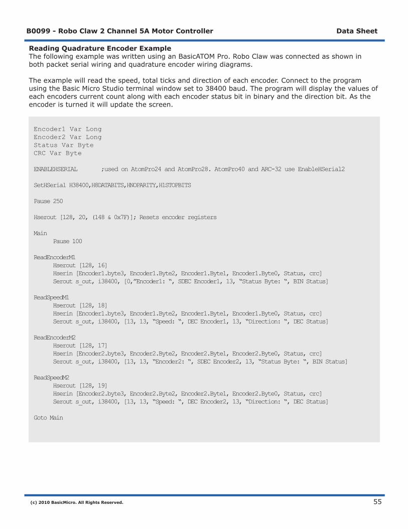
Reading Quadrature Encoder ExampleThefollowingexamplewaswrittenusinganBasicATOMPro.RoboClawwasconnectedasshowninbothpacketserialwiringandquadratureencoderwiringdiagrams.
Theexamplewillreadthespeed,totalticksanddirectionofeachencoder.ConnecttotheprogramusingtheBasicMicroStudioterminalwindowsetto38400baud.Theprogramwilldisplaythevaluesofeachencoderscurrentcountalongwitheachencoderstatusbitinbinaryandthedirectionbit.Astheencoderisturneditwillupdatethescreen.
Encoder1 Var LongEncoder2 Var LongStatus Var ByteCRC Var Byte
ENABLEHSERIAL ;used on AtomPro24 and AtomPro28. AtomPro40 and ARC-32 use EnableHSerial2
SetHSerial H38400,H8DATABITS,HNOPARITY,H1STOPBITS
Pause 250
Hserout [128, 20, (148 & 0x7F)]; Resets encoder registers
Main Pause 100
ReadEncoderM1 Hserout [128, 16] Hserin [Encoder1.byte3, Encoder1.Byte2, Encoder1.Byte1, Encoder1.Byte0, Status, crc] Serout s_out, i38400, [0,”Encoder1: “, SDEC Encoder1, 13, “Status Byte: “, BIN Status]
ReadSpeedM1 Hserout [128, 18] Hserin [Encoder1.byte3, Encoder1.Byte2, Encoder1.Byte1, Encoder1.Byte0, Status, crc] Serout s_out, i38400, [13, 13, “Speed: “, DEC Encoder1, 13, “Direction: “, DEC Status]
ReadEncoderM2 Hserout [128, 17] Hserin [Encoder2.byte3, Encoder2.Byte2, Encoder2.Byte1, Encoder2.Byte0, Status, crc] Serout s_out, i38400, [13, 13, “Encoder2: “, SDEC Encoder2, 13, “Status Byte: “, BIN Status]
ReadSpeedM2 Hserout [128, 19] Hserin [Encoder2.byte3, Encoder2.Byte2, Encoder2.Byte1, Encoder2.Byte0, Status, crc] Serout s_out, i38400, [13, 13, “Speed: “, DEC Encoder2, 13, “Direction: “, DEC Status]
Goto Main

(c) 2010 BasicMicro. All Rights Reserved.
B0099 - Robo Claw 2 Channel 5A Motor Controller Data Sheet
56
Speed Controlled by Quadrature Encoders ExampleThefollowingexamplewaswrittenusinganBasicATOMPro.RoboClawwasconnectedasshowninbothpacketserialwiringandquadratureencoderwiringdiagrams.
Theexamplewillcommanda4wheelrobottomoveforward,backward,rightturnandleftturnslowly.YoucanchangethespeedbyadjustingthevalueofSpeedandSpeed2variables.
CMD var byteSpeed var longSpeed2 var longCRC var byteAddress con 128
ENABLEHSERIAL ;used on AtomPro24 and AtomPro28. AtomPro40 and ARC-32 use EnableHSerial2SetHSerial H38400,H8DATABITS,HNOPARITY,H1STOPBITS
Mixed_Forward CMD=37 Speed=12000 Speed2=12000 CRC = (address + cmd + speed.byte3 + speed.byte2 + speed.byte1 + speed.byte0 + | speed2.byte3 + speed2.byte2 + speed2.byte1 + speed2.byte0)&0x7F hserout [address,cmd,speed.byte3,speed.byte2,speed.byte1,speed.byte0, | speed2.byte3,speed2.byte2,speed2.byte1,speed2.byte0,crc] pause 4000
Mixed_Backward CMD=37 Speed=-12000 Speed2=-12000 CRC = (address + cmd + speed.byte3 + speed.byte2 + speed.byte1 + speed.byte0 + | speed2.byte3 + speed2.byte2 + speed2.byte1 + speed2.byte0)&0x7F hserout [address,cmd,speed.byte3,speed.byte2,speed.byte1,speed.byte0, | speed2.byte3,speed2.byte2,speed2.byte1,speed2.byte0,crc] pause 4000
Mixed_Left CMD=37 Speed=-12000 Speed2=12000 CRC = (address + cmd + speed.byte3 + speed.byte2 + speed.byte1 + speed.byte0 + | speed2.byte3 + speed2.byte2 + speed2.byte1 + speed2.byte0)&0x7F hserout [address,cmd,speed.byte3,speed.byte2,speed.byte1,speed.byte0, | speed2.byte3,speed2.byte2,speed2.byte1,speed2.byte0,crc] pause 4000
Mixed_Right CMD=37 Speed=12000 Speed2=-12000 CRC = (address + cmd + speed.byte3 + speed.byte2 + speed.byte1 + speed.byte0 + | speed2.byte3 + speed2.byte2 + speed2.byte1 + speed2.byte0)&0x7F hserout [address,cmd,speed.byte3,speed.byte2,speed.byte1,speed.byte0, | speed2.byte3,speed2.byte2,speed2.byte1,speed2.byte0,crc] pause 4000
Mixed_Stop CMD=37 Speed=0 Speed2=0 CRC = (address + cmd + speed.byte3 + speed.byte2 + speed.byte1 + speed.byte0 + | speed2.byte3 + speed2.byte2 + speed2.byte1 + speed2.byte0)&0x7F hserout [address,cmd,speed.byte3,speed.byte2,speed.byte1,speed.byte0, | speed2.byte3,speed2.byte2,speed2.byte1,speed2.byte0,crc]
stop
(c) 2010 BasicMicro. All Rights Reserved.
B0099 - Robo Claw 2 Channel 5A Motor Controller Data Sheet
57
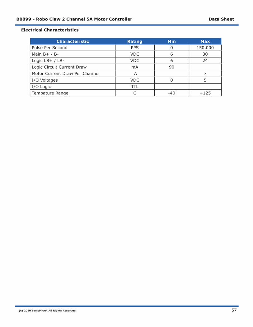
Electrical Characteristics
Characteristic Rating Min MaxPulsePerSecond PPS 0 150,000MainB+/B- VDC 6 30LogicLB+/LB- VDC 6 24LogicCircuitCurrentDraw mA 90MotorCurrentDrawPerChannel A 7I/OVoltages VDC 0 5I/OLogic TTLTempatureRange C -40 +125
(c) 2010 BasicMicro. All Rights Reserved.
B0099 - Robo Claw 2 Channel 5A Motor Controller Data Sheet
58
WarrantyBasicMicrowarrantiesitsproductsagainstdefectsinmaterialandworkmanshipforaperiodof90days.Ifadefectisdiscovered,BasicMicrowill,atourdiscretion,repair,replace,orrefundthepurchasepriceoftheproductinquestion.Contactusatsupport@basicmicro.com.Noreturnswillbeacceptedwithouttheproperauthorization.
Copyrights and TrademarksCopyright©2010byBasicMicro,Inc.Allrightsreserved.PICmicro®isatrademarkofMicrochipTechnology,Inc.TheBasicAtomandBasicMicroareregisteredtrademarksofBasicMicroInc.Othertrademarksmentionedareregisteredtrademarksoftheirrespectiveholders.
DisclaimerBasicMicrocannotbeheldresponsibleforanyincidental,orconsequentialdamagesresultingfromuseofproductsmanufacturedorsoldbyBasicMicrooritsdistributors.NoproductsfromBasicMicroshouldbeusedinanymedicaldevicesand/ormedicalsituations.Noproductshouldbeusedinalifesupportsituation.
Contacts Email:[email protected] Techsupport:[email protected] Web:http://www.basicmicro.com
Discussion ListAwebbaseddiscussionboardismaintainedathttp://www.basicmicro.com.
Technical SupportTechnicalsupportismadeavailablebysendinganemailtosupport@basicmicro.com.Allemailwillbeansweredwithin48hours.Allgeneralsyntaxandprogrammingquestions,unlessdeemedtobeasoftwareissue,willbereferredtotheon-linediscussionforums.


