38
B2020_OR002

B2020_OR002

B2020_OR002 Boone Bridge Replacement
Jeff Olson, PE| Quincy Engineering Jason B. Lloyd, PhD, PE | NSBA |
Bridge Steel Specialist | [email protected]
July 22, 2020
CONTENTS OF REPORT
Included in this report are the following sections:
Introduction
Design Assumptions
Information Provided
Design Summary
Cross Section Sketch
Girder Elevation Sketch
Steel Quantities
Appendix A – Client Request Forms
Appendix B – LRFD Simon Inputs
Note: The information contained in this document is not intended as a basis for structural design for this
or any project. Rather, it is a conceptual approach to the project that demonstrates the viability of the
steel framing system for project requirements, budget, and schedule.
This document has been prepared in accordance with information made available to the National Steel Bridge Alliance, a division of the American Institute of Steel Construction, at the time of its preparation. While it is believed to be accurate, it has not been prepared for conventional use as an engineering or construction document and should not be used or relied upon for any specific application without competent professional examination and verification of its accuracy, suitability and applicability by a licensed engineer, architect or other professional. AISC and NSBA disclaim any liability arising from information provided by others or from the unauthorized use of the information contained in this document.
INTRODUCTION
The conceptual solution and estimates for this project are based on parameters defined through bridge
design drawings received on July 6, 2020.
Number of Spans: 05 Span Lengths: 160’ – 240’ – 310’ – 240’ – 160’ Deck Out-to-Out Width: 148’ – 8” Support Skew Angle: 0 Curvature: None Design Specification: AASHTO LRFD BDS, 8th Edition Other: ODOT Bridge Design Manual (June 2020) Steel Grade: A709 Gr50W and A709 Gr70W Design Analysis Method: Line Girder Analysis using LRFD Simon
This conceptual study examined a continuous span steel bridge superstructure. Span lengths are
summarized above. The conceptual design is based on the Load and Resistance Factor Design method
in accordance with the AASHTO LRFD Bridge Design Specification, 8th Edition.

CONCEPTUAL SOLUTION: B2020_OR002 July 19, 2020
Design loading considered HL-93 loading and two user-defined design trucks as defined in the client
request forms provided by Quincy Engineering. The load factor for the user-defined design trucks is 1.35,
which is reflected in the axle loads by the ratio of load factors (1.35/1.75) before inputting them into the
line girder analysis model. Thus, LRFD Simon is able to evaluate the trucks using the user-defined load
factor and axle weights.
Live load deflection factor of L/800 was used.
A 44’ minimum width for phased construction was included in the considerations for girder spacing.
Field splices are not specifically designed as part of this conceptual study. However, they are indicated
on the elevation sketch at potential locations. Cross-frames and diaphragms are not explicitly designed as
part of this conceptual study. Weights of these secondary components are applied as uniform loads for
girder design purposes and are included in the total weight.
DESIGN ASSUMPTIONS
The bridge steel conceptual solution for this project uses the following design assumptions:
1. ASTM A709 Grade 50W steel is used throughout with the exception of the flange plates located
at the piers for the main span, which are ASTM A709 Grade 70W.
2. An 11-girder cross section is used. Girders are spaced at 14’-0”, with constant deck overhangs
on each side of 4’-4”. This gives an out to out deck width of 148’-8”. This results in a deck
overhang to span ratio of about 0.31, which is the in the range of providing a good deck
span/cantilever balance.
3. An 10.5” thick concrete deck, including a ½” sacrificial wearing surface is assumed, based on
ODOT bridge deck design table using the 14’ girder spacing. The concrete deck weight includes
the 10.5” thick deck and 2” concrete haunch above the top flange. The noncomposite dead load
distributed to the interior girder is taken as 2032.5 lb/ft, and 1652.1 lb/ft for the exterior girder.
4. An assumed uniform cross frame spacing is used along the length of the girder for design
purposes. A uniform cross frame dead load weight of 25 lb/ft is assumed, and is placed in on the
interior girders, and along the exterior girders. This weight is computed for the cross-frame
members only.
5. Future wearing surface load of 40 psf is applied.
6. A uniform noncomposite dead load of 10 psf for stay-in-place concrete forms is included.
7. Barrier dead load for the exterior bridge rails is 540 lb/ft with an even distribution to each girder.
The Median Barrier dead load is 700 lb/ft with an even distribution to each girder.

CONCEPTUAL SOLUTION: B2020_OR002 July 19, 2020
8. A miscellaneous steel detail weight to account for stiffeners, field splices, cross-frame gussets,
studs, and etc. is used. This weight is assumed as 5 lb/ft, and is placed on interior and exterior
girders as a uniformly distributed load.
9. The concrete deck is assumed to be placed all at once. A deck pour sequence is not considered.
10. The conceptual design only considers dead and live loads. Other loading conditions such as
thermal, wind, braking, etc. are not considered.
11. AASHTO live load distribution factors are assumed reasonably accurate for the main span
despite exceeding AASHTO span length recommendation. This assumption is supported by
conclusions in the following article: https://www.aisc.org/globalassets/nsba/conference-
proceedings/2014/olds---2014-wsbs-final.pdf.
INFORMATION PROVIDED
The following bridge design drawings were provided to NSBA.
CONCEPTUAL SOLUTION: B2020_OR002 July 19, 2020
DESIGN SUMMARY
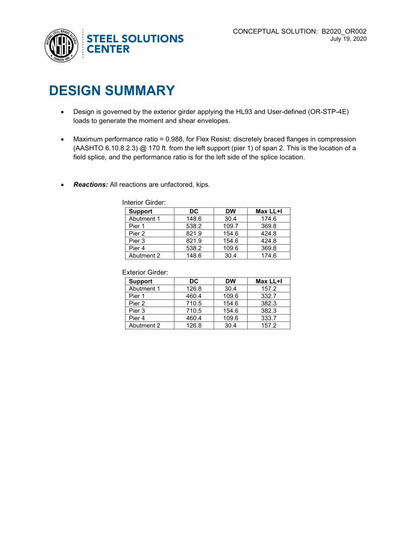
Design is governed by the exterior girder applying the HL93 and User-defined (OR-STP-4E)
loads to generate the moment and shear envelopes.
Maximum performance ratio = 0.988, for Flex Resist: discretely braced flanges in compression
(AASHTO 6.10.8.2.3) @ 170 ft. from the left support (pier 1) of span 2. This is the location of a
field splice, and the performance ratio is for the left side of the splice location.
Reactions: All reactions are unfactored, kips.
Interior Girder:
Support DC DW Max LL+I Abutment 1 148.6 30.4 174.6 Pier 1 538.2 109.7 369.8 Pier 2 821.9 154.6 424.8 Pier 3 821.9 154.6 424.8 Pier 4 538.2 109.6 369.8 Abutment 2 148.6 30.4 174.6
Exterior Girder:
Support DC DW Max LL+I Abutment 1 126.8 30.4 157.2 Pier 1 460.4 109.6 332.7 Pier 2 710.5 154.6 382.3 Pier 3 710.5 154.6 382.3 Pier 4 460.4 109.6 333.7 Abutment 2 126.8 30.4 157.2
CONCEPTUAL SOLUTION: B2020_OR002 July 19, 2020
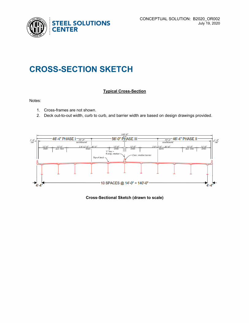
CROSS-SECTION SKETCH
Typical Cross-Section
Notes:
1. Cross-frames are not shown.
2. Deck out-to-out width, curb to curb, and barrier width are based on design drawings provided.
Cross-Sectional Sketch (drawn to scale)

CONCEPTUAL SOLUTION: B2020_OR002 July 19, 2020
GIRDER ELEVATION SKETCH
Girder Elevation
Notes:
1. Cross-frame connection plates are not shown.
2. Shear studs are not shown.
3. Transverse stiffeners are needed on only one side of the web at the end of the spans, near the
supports. There is one stiffener in span 1, three stiffeners in span 2, and six stiffeners in span 3.
Stiffener plates are provided in the following table:
Span Width (in)
Thickness (in)
Location (ft)
Location (ft)
Location (ft)
1 6 0.375 136 - -
2 6 0.375 24 - -
2 8 0.3125 192 216 -
3 8.75 0.5625 24 48 70
3 8 0.3125 250 262 286
4. Bearing stiffeners are on each side of the web at each support. Bearing stiffener sizes are as
follows: Abut 1: 8” x ¾”, Pier 1: 8” x 1-3/8”, Pier 2: 15” x 1-5/16”, Pier 3: 15” x 1-5/16”, Pier 4:
same as Pier 1, Abut 2: same as Abut 1.
5. Field splices are optional and shown for shipping and handling purposes.
6. All steel is ASTM A709 Grade 50W with ASTM Gr70W top and bottom flanges over piers.
7. The length and weight of the girder extensions beyond the centerline of bearing at the abutments
are not included in the weight computations.

CONCEPTUAL SOLUTION: B2020_OR002 July 19, 2020
Girder Elevation
STEEL QUANTITIES
The bridge steel conceptual solution for this project results in the following weights. These weights are
computed from the exterior girder, which controlled this design:
Girders, flanges, webs, and transvers & bearing stiffener = 293.1 tons
Cross-frames, Field splices, misc. details (assumed to be 5% of girder weight) = 14.7 tons
Girder Total (per girder line) = 307.8 tons
Bridge Total = 3,385.8 tons (41.4 psf deck area)

CONCEPTUAL SOLUTION: B2020_OR002 July 19, 2020
APPENDIX A – Client Request Forms
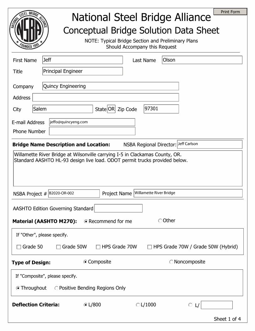
Sheet 1 of 4
National Steel Bridge AllianceConceptual Bridge Solution Data Sheet
Bridge Name Description and Location:
First Name
Company
Address
City State Zip Code
Phone Number
Last Name
NOTE: Typical Bridge Section and Preliminary Plans Should Accompany this Request
E-mail Address
Title
Material (AASHTO M270): Recommend for me Other
If "Other", please specify.
Type of Design: Composite Noncomposite
Throughout Positive Bending Regions Only
If "Composite", please specify.
Deflection Criteria: L/800 L/1000 L/
Grade 50 Grade 50W HPS Grade 70W HPS Grade 70W / Grade 50W (Hybrid)
NSBA Project # Project Name
AASHTO Edition Governing Standard
NSBA Regional Director:
Print Form
Willamette River Bridge at Wilsonville carrying I-5 in Clackamas County, OR. Standard AASHTO HL-93 design live load. ODOT permit trucks provided below.
Jeff
Quincy Engineering
Salem OR 97301
Olson
Principal Engineer

Sheet 2 of 4
Design Permit Load/Transit/Other Vehicle Description:
Supply axle loads and spacings for each special design vehicle below. If none, leave this section blank.
Axle Spacing (ft)
Axle Load (kips)
Axle Index
1 2 3 4 5 6 7 8 9 10 11 12 13 14 15 16 17 18 19 20
1/2 2/3 3/4 4/5 5/6 6/7 7/8 8/9 9/10 10/11 11/12 12/13 13/14 14/15 15/16 16/17 17/18 18/19 19/20
Vehicle Type
Yes NoImpact Factor: Applied to Vehicle Load Only
Yes NoUniform Loads Included?(If yes, please specify)
Load Applied in: Single Lane Single Lane with HL93 in all other LanesMultiple Lanes
Live Load Factor:
Uniform Load (k/ft):
Uniform Load (k/ft):
12 24 24 24 24 24 24 24 24
Design Permit
1.33
1.35
18 20 20 20 20 20 20 20 20 20 20 20 20
Design Permit
1.33
1.35

Sheet 3 of 4
Number of lanes available to trucks:
Fatigue Criteria:
ADTT (Not Single Lane):
Design Life (Years):
Slab Concrete f'c (psi):
Rebar Yield Fyr (ksi):
Stud Diameter (in):
Concrete Deck:
Design Permit Load/Transit/Other Vehicle Description (continued):
Supply axle loads and spacings for each special design vehicle below. If none, leave this section blank.
Dead Loads:
Traffic Barrier (each)
Median (each)
Sidewalk (each)
Utilities (Composite)
lb/ft
lb/ft
lb/ft
lb/ft
Pedestrian Railing (each)
Future Wearing Surface
Initial Overlay
Stay-in-Place Forms
lb/ft
lb/sq-ft
lb/sq-ft
lb/sq-ft
Utilities (Non-Comp) lb/ft
Axle Spacing (ft)
Axle Load (kips)
Axle Index
1 2 3 4 5 6 7 8 9 10 11 12 13 14 15 16 17 18 19 20
1/2 2/3 3/4 4/5 5/6 6/7 7/8 8/9 9/10 10/11 11/12 12/13 13/14 14/15 15/16 16/17 17/18 18/19 19/20
Vehicle Type
Yes NoImpact Factor: Applied to Vehicle Load Only
Yes NoUniform Loads Included?(If yes, please specify) Uniform Load (k/ft):
Load Applied in: Single Lane Single Lane with HL93 in all other LanesMultiple Lanes
Live Load Factor:
75
4,000
60
540
700
0
0
0
40
0
0
0
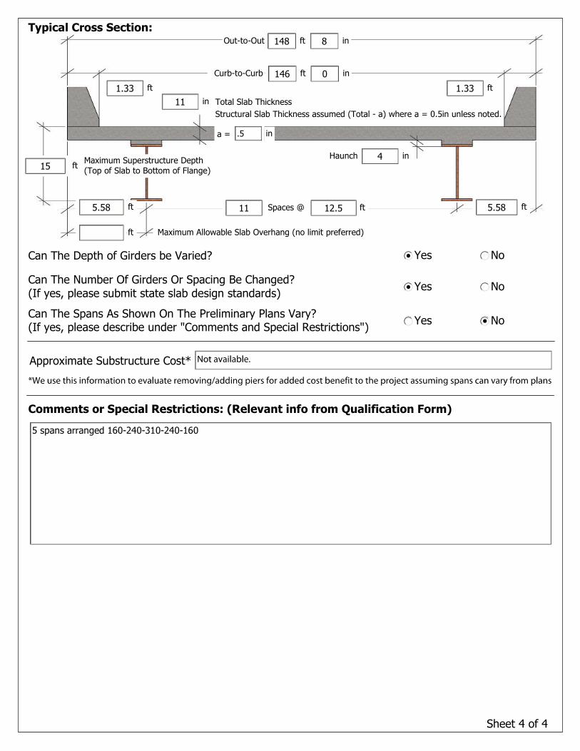
Sheet 4 of 4
Can The Number Of Girders Or Spacing Be Changed? (If yes, please submit state slab design standards)
Can The Spans As Shown On The Preliminary Plans Vary? (If yes, please describe under "Comments and Special Restrictions")
Yes No
Yes No
Can The Depth of Girders be Varied? Yes No
Comments or Special Restrictions: (Relevant info from Qualification Form)
Typical Cross Section:
Spaces @ ft
Maximum Allowable Slab Overhang (no limit preferred)
Total Slab Thickness
in
in
ftft
Haunch
ft
ft ft
inftCurb-to-Curb
inftOut-to-Out
ftMaximum Superstructure Depth (Top of Slab to Bottom of Flange)
Structural Slab Thickness assumed (Total - a) where a = 0.5in unless noted.
a = in
Approximate Substructure Cost*
5.5811
15
11
1.33
146
4
1.33
5 spans arranged 160-240-310-240-160
12.55.58
0
148 8
.5
Regional Director: Jeff Carlson
NSBA Steel Specialist: Jason Lloyd
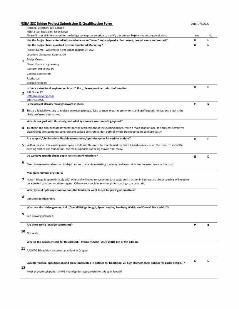
Please fill out all information for the bridge conceptual solution to qualify the project before requesting a solution. Yes No
Has the Project been entered into salesforce as an "event" and assigned a client name, project name and contact?
Has the project been qualified by your Director of Marketing?
Project Name: Willamette River Bridge (B2020-OR-002)
Location: Clackamas County, OR
Bridge Owner:
Client: Quincy Engineering
Contact: Jeff Olson, PE
General Contractor:
Fabricator:
Bridge Engineer:
Is there a structural engineer on board? If so, please provide contact information.
Jeff Olson, PE
503-763-9995
Is the project already moving forward in steel?
This is a feasibility study to replace an existing bridge. Due to span length requirements and profile grade limitations, steel is the
likely preferred alternative.
What is our goal with this study, and what system are we competing against?
To obtain the approximate level cost for the replacement of the existing bridge. With a main span of 310', the only cost effective
alternatives are segmental concrete and spliced concrete girder, both of which are expected to be more costly.
Are support/pier locations flexible to maximize/optimize spans for various options?
Within reason. The existing main span is 250' and this must be maintained for Coast Guard clearances on the river. To avoid the
existing timber pile foundation, the main supports are being moved ~30' away.
Do we have specific girder depth restrictions/limitations?
Need to use reasonable span to depth ratios to maintain existing roadway profile or minimize the need to raise the road.
Minimum number of girders?
None - Bridge is approximately 150' wide and will need to accommodate stage construction in 3 phases so girder spacing will need to
be adjusted to accommodate staging. Otherwise, should maximize girder spacing - to - cost ratio.
What type of options/scenarios does the fabricator want to see for pricing alternatives?
Constant depth girders
What are the bridge geometrics? (Overall Bridge Length, Span Lengths, Roadway Width, and Overall Deck Width?)
See drawing provided.
Are there splice location constraints?
Not really
What is the design criteria for this project? Typically AASHTO LRFD BDS 8th or 9th Edition.
AASHTO 8th edition is current standard in Oregon.
Specific material specification and grade (Interested in options for traditional vs. high strength steel options for girder design?)?
Most economical grade. IS HPS hybrid girder appropriate for this span length?
4
5
6
7
9
NSBA SSC Bridge Project Submission & Qualification Form
2
1
Date: 7/5/2020
3
8
10
11
12

Any specific overriding state DOT bridge manual requirements? Please provide State BDM references below for design
requirements (superimposed dead load distribution, deflection criteria, permit vehicles that need to be investigated, etc.).
See attached
Any other site constraints? Water crossing, access limitations, etc.
Water crossing - cannot get large barge to site so will need to truck to site and splice
Girders Curved? If so what is the Radius at the Bridge Centerline?
No
Steel Tubs or Steel I-Girders?
Whichever is most economical
Shipping constraints (state weight/length restrictions)
Normal length constraints are about 140'. Weight is a function of hauling axle configuration
Skew? If so, what angle per AASHTO LRFD BDS (Skew Angle - Angle between the centerline of support and a line normal to the
roadway centerline)?
None
What is the deadline from the SSC to you (pre-pricing deadline)?
2-3 weeks
Is a girder required at the bridge centerline for future redecking of the bridge?
no
Will the bridge be built using phased construction? If so, indicate the phased construction lines.
3 phases. Each phase must be minimum of 44' clear width for traffic.
Other:
22
15
14
13
19
18
17
16
20
21

CONCEPTUAL SOLUTION: B2020_OR002 July 19, 2020
APPENDIX B – LRFD Simon Inputs

Project: Boone Bridge Replacement Computed: JBL Date: 07/12/20
Subject: Steel Bridge Conceptual Solution Checked: DAA Date: 07/14/20
Task: SIMON Inputs & Loads Page: of:
Job #: B2020_OR_002 No:
Span Arrangement
Notes:
1 Permit truck axle loads were modified for reduced live load factor of 1.35 by multiplying the axle loads by (1.35/175).
2 Type OR-STP-4E permit truck controls over Type OR-STP-5BW for all moments and shears of this bridge.
3
SIMON Inputs (General Properties)
Superstructure Type I-Girder
Number of Spans 5
Number of Girders 11
Roadway Width 146.00 ft
Number of Lanes 12
Run Option LRFD Design
Redesign Performance
Ratio 0.90
Maximum Performance
Ratio 1.01
Minimum Flange Thickness 0.75 in
Maximum Plate Thickness 3 in
Distance From Bottom of
Slab to cg Rebar 5.3500 in
Distance From Bottom of
Slab to Top of Web 4 in
ADTT (Single Lane) 1500 trucks/day
Fatigue Service Life 75 years

Project: Boone Bridge Replacement Computed: JBL Date: 07/12/20
Subject: Steel Bridge Conceptual Solution Checked: DAA Date: 07/14/20
Task: SIMON Inputs & Loads Page: of:
Job #: B2020_OR_002 No:
SIMON Inputs (Distribution Factors)
Distribution Factors Program Defined
Girder Skew 0 degrees
Bridge Deck Out-to-Out
Width 148.667 ft
Overhang Width 4.333 ft
Girder Spacing 14.000 ft
Rail Width (on controlling
exterior side) 1.333 ft
Distance from Exterior
Web to Face of Rail (de) 3.00 ft
Girder Location Exterior
User Input Moment
Distribution Factor
Single Lane NA
Multiple Lane NA
User Input Shear
Distribution Factor
Single Lane NA
Multiple Lane NA
SIMON Inputs (Material Properties)
Concrete Slab Compressive
Strength 4000 psi
Density of Concrete 0.145 kcf
Modulus of Concrete 3987 ksi
Modulus of Steel 29000 ksi
Modular Ratio, n 7.3
Reinforcement Yield
Strength 60 ksi
Longitudinal Stiffener Yield
Strength 50 ksi
Transverse and Bearing
Stiffener Yield Strength 50 ksi
Concrete Type Normal Weight Concrete
Steel Surface Condition Weathering Steel
Connection Plate Type Welded Connection Plates
Slab Meet AASHTO LRFD
6.10.1.7 Yes

Project: Boone Bridge Replacement Computed: JBL Date: 07/12/20
Subject: Steel Bridge Conceptual Solution Checked: DAA Date: 07/14/20
Task: SIMON Inputs & Loads Page: of:
Job #: B2020_OR_002 No:
SIMON Inputs (Loads Tab)
Composite Loads (DC2):
Girder DF%
Traffic Barrier 1 540 plf Equal
Traffic Barrier 2 540 plf Equal
Median 700 plf Equal
Trail Walkway 0 plf 0.0
Bridge Composite DL 1780.0 plf
Girder Composite DL 161.8 plf
Bridge Utility DL 0 plf
Girder Utility DL 0 plf
Initial Wearing Surface Pressure
Pressure Magnitude 0 psf
Thickness 0 in
Density NA kcf
Pressure 0.0 psf
Future Wearing Surface Pressure
Pressure Magnitude 40 psf
Thickness 0.5 in
Density NA kcf
Pressure 40.0 psf
Bridge Composite DW 5840.0 plf
Method of Distribution Spread Evenly
Wearing Surface Total 530.9 plf
Design Vehicle Option HL93/User Defined Design Vehicle (envelope)
Live Load Deflection Factor 800
Pedestrian Live Load 0 plf
Design Vehicle IM 1.33
Fatigue Vehicle IM 1.15

Project: Boone Bridge Replacement Computed: JBL Date: 07/12/20
Subject: Steel Bridge Conceptual Solution Checked: DAA Date: 07/14/20
Task: SIMON Inputs & Loads Page: of:
Job #: B2020_OR_002 No:
SIMON Inputs (User Defined Design Vehicle Properties)
Distribution Factor Type
For Truck Both
Distribution Factor Type
For Lane Both
Lane Live Load 0 klf
Include All Axles Yes
Axle Number Axle Load (k) Axle Spacing (ft)
1 13.89 12.0
2 15.43 5.5
3 15.43 4.5
4 15.43 15.0
5 15.43 5.0
6 15.43 5.0
7 15.43 43.0
8 15.43 5.0
9 15.43 5.0
10 15.43 16.0
11 15.43 5.0
12 15.43 5.0
13 15.43 0.0
SIMON Inputs (Transverse Stiffener Properties)
Maximum Transverse
Stiffener Spacing 360 in
One Sided Transverse
Stiffeners Yes
SIMON Inputs (Shear Stud Properties)
Shear Connector Design Yes
Distance From Interior
Support to Nearest Shear
Connector 0 ft
Concrete Weight Used to
Calculate Concrete Elastic
Modulus 145 pcf
Desirable Pitch Increment 3 in
Stud Properties
Diameter 0.875 in
Length 6 in
Studs Per Row 3

Project: Boone Bridge Replacement Computed: JBL Date: 07/12/20
Subject: Steel Bridge Conceptual Solution Checked: DAA Date: 07/14/20
Task: SIMON Inputs & Loads Page: of:
Job #: B2020_OR_002 No:
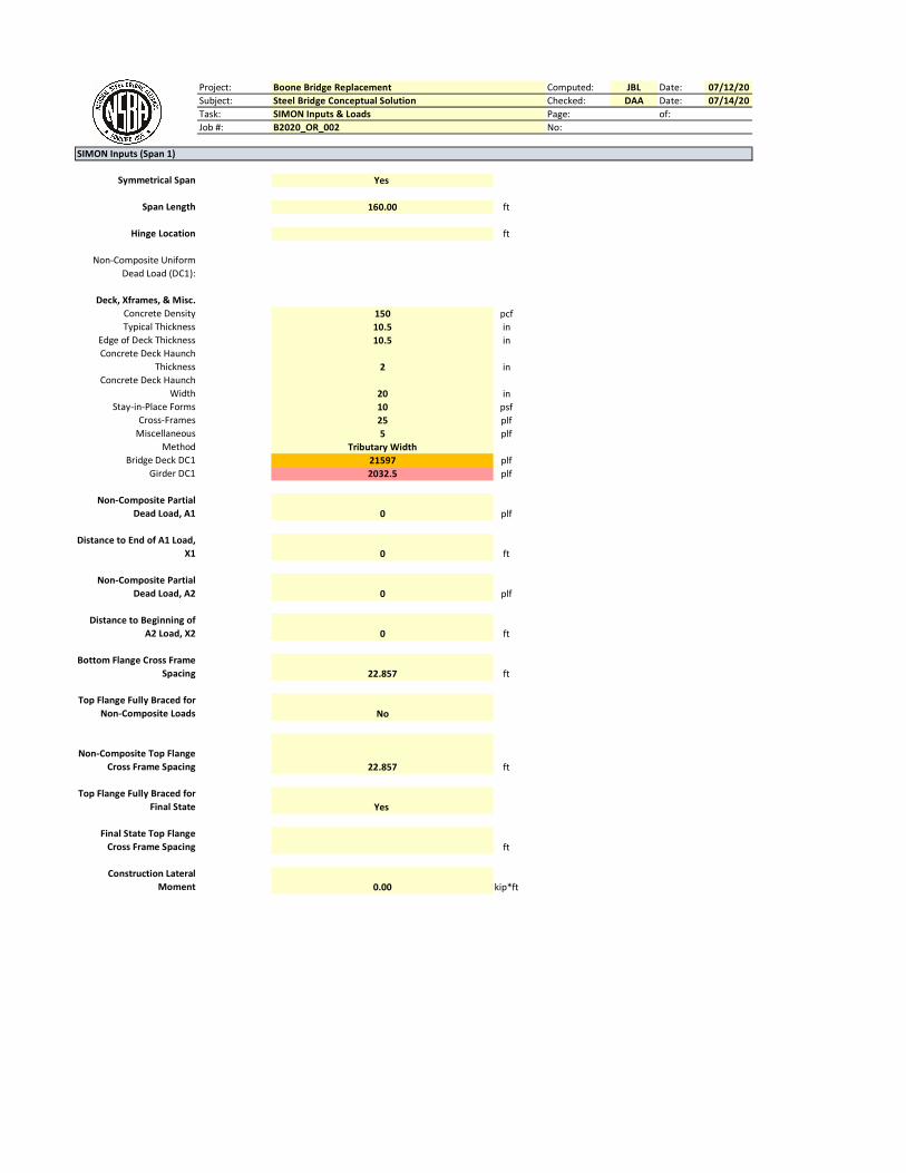
SIMON Inputs (Span 1)
Symmetrical Span Yes
Span Length 160.00 ft
Hinge Location ft
Non-Composite Uniform
Dead Load (DC1):
Deck, Xframes, & Misc.
Concrete Density 150 pcf
Typical Thickness 10.5 in
Edge of Deck Thickness 10.5 in
Concrete Deck Haunch
Thickness 2 in
Concrete Deck Haunch
Width 20 in
Stay-in-Place Forms 10 psf
Cross-Frames 25 plf
Miscellaneous 5 plf
Method Tributary Width
Bridge Deck DC1 21597 plf
Girder DC1 1652.1 plf
Non-Composite Partial
Dead Load, A1 0 plf
Distance to End of A1 Load,
X1 0 ft
Non-Composite Partial
Dead Load, A2 0 plf
Distance to Beginning of
A2 Load, X2 0 ft
Bottom Flange Cross Frame
Spacing 22.857 ft
Top Flange Fully Braced for
Non-Composite Loads No
Non-Composite Top Flange
Cross Frame Spacing 22.857 ft
Top Flange Fully Braced for
Final State Yes
Final State Top Flange
Cross Frame Spacing ft
Construction Lateral
Moment 0.00 kip*ft

Project: Boone Bridge Replacement Computed: JBL Date: 07/12/20
Subject: Steel Bridge Conceptual Solution Checked: DAA Date: 07/14/20
Task: SIMON Inputs & Loads Page: of:
Job #: B2020_OR_002 No:
SIMON Inputs (Span 2)
Symmetrical Span Yes
Span Length 240.00 ft
Hinge Location ft
Non-Composite Uniform
Dead Load (DC1):
Deck, Xframes, & Misc.
Concrete Density 150 pcf
Typical Thickness 10.5 in
Edge of Deck Thickness 10.5 in
Concrete Deck Haunch
Thickness 2 in
Concrete Deck Haunch
Width 20 in
Stay-in-Place Forms 10 psf
Cross-Frames 25 plf
Miscellaneous 5 plf
Method Tributary Width
Bridge Deck DC1 21597 plf
Girder DC1 1652.1 plf
Non-Composite Partial
Dead Load, A1 0 plf
Distance to End of A1 Load,
X1 0 ft
Non-Composite Partial
Dead Load, A2 0 plf
Distance to Beginning of
A2 Load, X2 0 ft
Bottom Flange Cross Frame
Spacing 24.00 ft
Top Flange Fully Braced for
Non-Composite Loads No
Non-Composite Top Flange
Cross Frame Spacing 24.00 ft
Top Flange Fully Braced for
Final State Yes
Final State Top Flange
Cross Frame Spacing ft
Construction Lateral
Moment 0.00 kip*ft

Project: Boone Bridge Replacement Computed: JBL Date: 07/12/20
Subject: Steel Bridge Conceptual Solution Checked: DAA Date: 07/14/20
Task: SIMON Inputs & Loads Page: of:
Job #: B2020_OR_002 No:
SIMON Inputs (Span 3)
Symmetrical Span Yes
Span Length 310.00 ft
Hinge Location ft
Non-Composite Uniform
Dead Load (DC1):
Deck, Xframes, & Misc.
Concrete Density 150 pcf
Typical Thickness 10.5 in
Edge of Deck Thickness 10.5 in
Concrete Deck Haunch
Thickness 2 in
Concrete Deck Haunch
Width 20 in
Stay-in-Place Forms 10 psf
Cross-Frames 25.000 plf
Miscellaneous 5 plf
Method Tributary Width
Bridge Deck DC1 21597 plf
Girder DC1 1652.1 plf
Non-Composite Partial
Dead Load, A1 0 plf
Distance to End of A1 Load,
X1 0 ft
Non-Composite Partial
Dead Load, A2 0 plf
Distance to Beginning of
A2 Load, X2 0 ft
Bottom Flange Cross Frame
Spacing 23.85 ft
Top Flange Fully Braced for
Non-Composite Loads No
Non-Composite Top Flange
Cross Frame Spacing 23.85 ft
Top Flange Fully Braced for
Final State Yes
Final State Top Flange
Cross Frame Spacing ft
Construction Lateral
Moment 0.00 kip*ft

Project: Boone Bridge Replacement Computed: JBL Date: 07/12/20
Subject: Steel Bridge Conceptual Solution Checked: DAA Date: 07/14/20
Task: SIMON Inputs & Loads Page: of:
Job #: B2020_OR_002 No:
SIMON Inputs (Span 1)
SIMON Inputs (Web Cross Section Information)
End Location
(ft)
Vertical Web
Depth, Left
(in)
Vertical Web
Depth, Right
(in)
Web Fy
(ksi)
Web
Thickness
(in)
Transversely
Stiffened
Top
Longitudinal
Stiffener
Width (in)
Top
Longitudinal
Stiffener
Thickness (in)
Bottom
Longitudinal
Stiffener
Width (in)
Bottom
Longitudinal
Stiffener
Thickness
(in)
Reduce
Web
Thickness
Min
Transverse
Stiffener
Spacing (in)
40.00 96.00 96.00 50 0.8125 Yes 24
80.00 96.00 96.00 50 0.8125 Yes 24
120.00 96.00 96.00 50 0.8125 Yes 24
160.00 96.00 96.00 50 0.8125 Yes 24
SIMON Inputs (Top Flange Cross Section Information)
End Location
(ft)
Top Flange
Width (in)
Top Flange
Thickness (in)
Top
Flange Fy
(ksi)
Top Flange
Fu (ksi)
40.00 18.00 1.00 50 70
80.00 18.00 1.00 50 70
120.00 18.00 1.00 50 70
145.00 18.00 1.00 70 85
160.00 18.00 1.50 70 85
SIMON Inputs (Bottom Flange Cross Section Information)
End Location
(ft)
Bottom
Flange Width
(in)
Bottom
Flange
Thickness (in)
Bottom
Flange Fy
(ksi)
Bottom
Flange Fu
(ksi)
40.00 18.00 1.00 50 70
80.00 18.00 1.00 50 70
120.00 18.00 1.00 50 70
145.00 24.00 1.50 70 85
160.00 24.00 2.625 70 85

Project: Boone Bridge Replacement Computed: JBL Date: 07/12/20
Subject: Steel Bridge Conceptual Solution Checked: DAA Date: 07/14/20
Task: SIMON Inputs & Loads Page: of:
Job #: B2020_OR_002 No:
SIMON Inputs (Slab Cross Section Information)
End Location
(ft)
Effective
Composite
Slab Width
(in)
Effective
Composite
Slab
Thickness (in)
Rebar
Area
(in^2) Composite
120.00 136.00 10.00 15.19 Yes
160.00 136.00 10.00 15.19 Yes
Deck Rebar cg:
Deck Thickness 10.5 in
Cover Top 2.5 in
Cover Bottom 1 in
Rebar Dia 0.625 in
cg 5.354166667 in
SIMON Inputs (Field Splice)
Field Splice
Location (ft) .7L 0.75L 0.8L
120.00 112 120 128
SIMON Inputs (Deck Pours)
Pour Number
Pour Start
Location (ft)
Pour End
Location (ft)
SIMON Inputs (Span 2)
SIMON Inputs (Web Cross Section Information)
End Location
(ft)
Vertical Web
Depth, Left
(in)
Vertical Web
Depth, Right
(in)
Web Fy
(ksi)
Web
Thickness
(in)
Transversely
Stiffened
Top
Longitudinal
Stiffener
Width (in)
Top
Longitudinal
Stiffener
Thickness (in)
Bottom
Longitudinal
Stiffener
Width (in)
Bottom
Longitudinal
Stiffener
Thickness
(in)
Reduce
Web
Thickness
Min
Transverse
Stiffener
Spacing (in)
40.00 96.00 96.00 50 0.8125 Yes 24
60.00 96.00 96.00 50 0.8125 Yes 24
120.00 96.00 96.00 50 0.8125 Yes 24
170.00 96.00 96.00 50 0.8125 Yes 24
180.00 96.00 96.00 50 0.8125 Yes 24
240.00 96.00 96.00 50 0.8125 Yes 24
SIMON Inputs (Top Flange Cross Section Information)
End Location
(ft)
Top Flange
Width (in)
Top Flange
Thickness (in)
Top
Flange Fy
(ksi)
Top Flange
Fu (ksi)
15.00 18.00 1.50 70 85
40.00 18.00 1.00 70 85
60.00 18.00 1.00 50 70
120.00 18.00 1.00 50 70
170.00 18.00 1.00 50 70
180.00 32.00 1.75 70 85
220.00 32.00 1.75 70 85
240.00 32.00 2.375 70 85

Project: Boone Bridge Replacement Computed: JBL Date: 07/12/20
Subject: Steel Bridge Conceptual Solution Checked: DAA Date: 07/14/20
Task: SIMON Inputs & Loads Page: of:
Job #: B2020_OR_002 No:
SIMON Inputs (Bottom Flange Cross Section Information)
End Location
(ft)
Bottom
Flange Width
(in)
Bottom
Flange
Thickness (in)
Bottom
Flange Fy
(ksi)
Bottom
Flange Fu
(ksi)
15.00 24.00 2.625 70 85
40.00 24.00 1.50 70 85
60.00 18.00 1.875 50 70
120.00 18.00 1.875 50 70
170.00 18.00 1.875 50 70
180.00 32.00 2.00 70 85
220.00 32.00 2.00 70 85
240.00 32.00 3.00 70 85
SIMON Inputs (Slab Cross Section Information)
End Location
(ft)
Effective
Composite
Slab Width
(in)
Effective
Composite
Slab
Thickness (in)
Rebar
Area
(in^2) Composite
40.00 136.00 10.00 15.19 Yes
170.00 136.00 10.00 15.19 Yes
240.00 136.00 10.00 15.19 Yes
Deck Rebar cg:
Deck Thickness 10.5 in
Cover Top 2.5 in
Cover Bottom 1 in
Rebar Dia 0.625 in
cg 5.354166667 in
SIMON Inputs (Field Splice)
Field Splice
Location (ft) .7L 0.75L 0.8L
40.00 168 180 192
170.00
SIMON Inputs (Deck Pours)
Pour Number
Pour Start
Location (ft)
Pour End
Location (ft)
SIMON Inputs (Span 3)
SIMON Inputs (Web Cross Section Information)
End Location
(ft)
Vertical Web
Depth, Left
(in)
Vertical Web
Depth, Right
(in)
Web Fy
(ksi)
Web
Thickness
(in)
Transversely
Stiffened
Top
Longitudinal
Stiffener
Width (in)
Top
Longitudinal
Stiffener
Thickness (in)
Bottom
Longitudinal
Stiffener
Width (in)
Bottom
Longitudinal
Stiffener
Thickness
(in)
Reduce
Web
Thickness
Min
Transverse
Stiffener
Spacing (in)
70.00 96.00 96.00 50 0.8125 Yes 24
77.50 96.00 96.00 50 0.8125 Yes 24
155.00 96.00 96.00 50 0.8125 Yes 24
232.50 96.00 96.00 50 0.8125 Yes 24
240.00 96.00 96.00 50 0.8125 Yes 24
310.00 96.00 96.00 50 0.8125 Yes 24

Project: Boone Bridge Replacement Computed: JBL Date: 07/12/20
Subject: Steel Bridge Conceptual Solution Checked: DAA Date: 07/14/20
Task: SIMON Inputs & Loads Page: of:
Job #: B2020_OR_002 No:
SIMON Inputs (Top Flange Cross Section Information)
End Location
(ft)
Top Flange
Width (in)
Top Flange
Thickness (in)
Top
Flange Fy
(ksi)
Top Flange
Fu (ksi)
30.00 32.00 2.375 70 85
80.00 32.00 1.375 70 85
230.00 24.00 1.125 50 70
280.00 32.00 1.375 70 85
310.00 32.00 2.375 70 85
SIMON Inputs (Bottom Flange Cross Section Information)
End Location
(ft)
Bottom
Flange Width
(in)
Bottom
Flange
Thickness (in)
Bottom
Flange Fy
(ksi)
Bottom
Flange Fu
(ksi)
30.00 32.00 3.00 70 85
80.00 32.00 1.50 70 85
230.00 24.00 2.50 50 70
280.00 32.00 1.50 70 85
310.00 32.00 3.00 70 85
SIMON Inputs (Slab Cross Section Information)
End Location
(ft)
Effective
Composite
Slab Width
(in)
Effective
Composite
Slab
Thickness (in)
Rebar
Area
(in^2) Composite
80.00 136.00 10.00 15.19 Yes
230.00 136.00 10.00 15.19 Yes
310.00 136.00 10.00 15.19 Yes
Deck Rebar cg:
Deck Thickness 10.5 in
Cover Top 2.5 in
Cover Bottom 1 in
Rebar Dia 0.625 in
cg 5.354166667 in
SIMON Inputs (Field Splice)
Field Splice
Location (ft) .7L 0.75L 0.8L
80.00 217 232.5 248
230.00
SIMON Inputs (Deck Pours)
Pour Number
Pour Start
Location (ft)
Pour End
Location (ft)

Project: Boone Bridge Replacement Computed: JBL Date: 07/12/20
Subject: Steel Bridge Conceptual Solution Checked: DAA Date: 07/14/20
Task: SIMON Inputs & Loads Page: of:
Job #: B2020_OR_002 No:
Span Arrangement
Notes:
1 Permit truck axle loads were modified for reduced live load factor of 1.35 by multiplying the axle loads by (1.35/175).
2 Type OR-STP-4E permit truck controls over Type OR-STP-5BW for all moments and shears of this bridge.
3
SIMON Inputs (General Properties)
Superstructure Type I-Girder
Number of Spans 5
Number of Girders 11
Roadway Width 146.00 ft
Number of Lanes 12
Run Option LRFD Design
Redesign Performance
Ratio 0.90
Maximum Performance
Ratio 1.01
Minimum Flange Thickness 0.75 in
Maximum Plate Thickness 3 in
Distance From Bottom of
Slab to cg Rebar 5.3500 in
Distance From Bottom of
Slab to Top of Web 4 in
ADTT (Single Lane) 1500 trucks/day
Fatigue Service Life 75 years

Project: Boone Bridge Replacement Computed: JBL Date: 07/12/20
Subject: Steel Bridge Conceptual Solution Checked: DAA Date: 07/14/20
Task: SIMON Inputs & Loads Page: of:
Job #: B2020_OR_002 No:
SIMON Inputs (Distribution Factors)
Distribution Factors Program Defined
Girder Skew 0 degrees
Bridge Deck Out-to-Out
Width 148.667 ft
Overhang Width 4.333 ft
Girder Spacing 14.000 ft
Rail Width (on controlling
exterior side) 1.333 ft
Distance from Exterior
Web to Face of Rail (de) 3.00 ft
Girder Location Interior
User Input Moment
Distribution Factor
Single Lane NA
Multiple Lane NA
User Input Shear
Distribution Factor
Single Lane NA
Multiple Lane NA
SIMON Inputs (Material Properties)
Concrete Slab Compressive
Strength 4000 psi
Density of Concrete 0.145 kcf
Modulus of Concrete 3987 ksi
Modulus of Steel 29000 ksi
Modular Ratio, n 7.3
Reinforcement Yield
Strength 60 ksi
Longitudinal Stiffener Yield
Strength 50 ksi
Transverse and Bearing
Stiffener Yield Strength 50 ksi
Concrete Type Normal Weight Concrete
Steel Surface Condition Weathering Steel
Connection Plate Type Welded Connection Plates
Slab Meet AASHTO LRFD
6.10.1.7 Yes

Project: Boone Bridge Replacement Computed: JBL Date: 07/12/20
Subject: Steel Bridge Conceptual Solution Checked: DAA Date: 07/14/20
Task: SIMON Inputs & Loads Page: of:
Job #: B2020_OR_002 No:
SIMON Inputs (Loads Tab)
Composite Loads (DC2):
Girder DF%
Traffic Barrier 1 540 plf Equal
Traffic Barrier 2 540 plf Equal
Median 700 plf Equal
Trail Walkway 0 plf 0.0
Bridge Composite DL 1780.0 plf
Girder Composite DL 161.8 plf
Bridge Utility DL 0 plf
Girder Utility DL 0 plf
Initial Wearing Surface Pressure
Pressure Magnitude 0 psf
Thickness 0 in
Density NA kcf
Pressure 0.0 psf
Future Wearing Surface Pressure
Pressure Magnitude 40 psf
Thickness 0.5 in
Density NA kcf
Pressure 40.0 psf
Bridge Composite DW 5840.0 plf
Method of Distribution Spread Evenly
Wearing Surface Total 530.9 plf
Design Vehicle Option HL93/User Defined Design Vehicle (envelope)
Live Load Deflection Factor 800
Pedestrian Live Load 0 plf
Design Vehicle IM 1.33
Fatigue Vehicle IM 1.15

Project: Boone Bridge Replacement Computed: JBL Date: 07/12/20
Subject: Steel Bridge Conceptual Solution Checked: DAA Date: 07/14/20
Task: SIMON Inputs & Loads Page: of:
Job #: B2020_OR_002 No:
SIMON Inputs (User Defined Design Vehicle Properties)
Distribution Factor Type
For Truck Both
Distribution Factor Type
For Lane Both
Lane Live Load 0 klf
Include All Axles Yes
Axle Number Axle Load (k) Axle Spacing (ft)
1 13.89 12.0
2 15.43 5.5
3 15.43 4.5
4 15.43 15.0
5 15.43 5.0
6 15.43 5.0
7 15.43 43.0
8 15.43 5.0
9 15.43 5.0
10 15.43 16.0
11 15.43 5.0
12 15.43 5.0
13 15.43 0.0
SIMON Inputs (Transverse Stiffener Properties)
Maximum Transverse
Stiffener Spacing 360 in
One Sided Transverse
Stiffeners Yes
SIMON Inputs (Shear Stud Properties)
Shear Connector Design Yes
Distance From Interior
Support to Nearest Shear
Connector 0 ft
Concrete Weight Used to
Calculate Concrete Elastic
Modulus 145 pcf
Desirable Pitch Increment 3 in
Stud Properties
Diameter 0.875 in
Length 6 in
Studs Per Row 3
Project: Boone Bridge Replacement Computed: JBL Date: 07/12/20
Subject: Steel Bridge Conceptual Solution Checked: DAA Date: 07/14/20
Task: SIMON Inputs & Loads Page: of:
Job #: B2020_OR_002 No:
SIMON Inputs (Span 1)
Symmetrical Span Yes
Span Length 160.00 ft
Hinge Location ft
Non-Composite Uniform
Dead Load (DC1):
Deck, Xframes, & Misc.
Concrete Density 150 pcf
Typical Thickness 10.5 in
Edge of Deck Thickness 10.5 in
Concrete Deck Haunch
Thickness 2 in
Concrete Deck Haunch
Width 20 in
Stay-in-Place Forms 10 psf
Cross-Frames 25 plf
Miscellaneous 5 plf
Method Tributary Width
Bridge Deck DC1 21597 plf
Girder DC1 2032.5 plf
Non-Composite Partial
Dead Load, A1 0 plf
Distance to End of A1 Load,
X1 0 ft
Non-Composite Partial
Dead Load, A2 0 plf
Distance to Beginning of
A2 Load, X2 0 ft
Bottom Flange Cross Frame
Spacing 22.857 ft
Top Flange Fully Braced for
Non-Composite Loads No
Non-Composite Top Flange
Cross Frame Spacing 22.857 ft
Top Flange Fully Braced for
Final State Yes
Final State Top Flange
Cross Frame Spacing ft
Construction Lateral
Moment 0.00 kip*ft

Project: Boone Bridge Replacement Computed: JBL Date: 07/12/20
Subject: Steel Bridge Conceptual Solution Checked: DAA Date: 07/14/20
Task: SIMON Inputs & Loads Page: of:
Job #: B2020_OR_002 No:
SIMON Inputs (Span 2)
Symmetrical Span Yes
Span Length 240.00 ft
Hinge Location ft
Non-Composite Uniform
Dead Load (DC1):
Deck, Xframes, & Misc.
Concrete Density 150 pcf
Typical Thickness 10.5 in
Edge of Deck Thickness 10.5 in
Concrete Deck Haunch
Thickness 2 in
Concrete Deck Haunch
Width 20 in
Stay-in-Place Forms 10 psf
Cross-Frames 25 plf
Miscellaneous 5 plf
Method Tributary Width
Bridge Deck DC1 21597 plf
Girder DC1 2032.5 plf
Non-Composite Partial
Dead Load, A1 0 plf
Distance to End of A1 Load,
X1 0 ft
Non-Composite Partial
Dead Load, A2 0 plf
Distance to Beginning of
A2 Load, X2 0 ft
Bottom Flange Cross Frame
Spacing 24.00 ft
Top Flange Fully Braced for
Non-Composite Loads No
Non-Composite Top Flange
Cross Frame Spacing 24.00 ft
Top Flange Fully Braced for
Final State Yes
Final State Top Flange
Cross Frame Spacing ft
Construction Lateral
Moment 0.00 kip*ft

Project: Boone Bridge Replacement Computed: JBL Date: 07/12/20
Subject: Steel Bridge Conceptual Solution Checked: DAA Date: 07/14/20
Task: SIMON Inputs & Loads Page: of:
Job #: B2020_OR_002 No:
SIMON Inputs (Span 3)
Symmetrical Span Yes
Span Length 310.00 ft
Hinge Location ft
Non-Composite Uniform
Dead Load (DC1):
Deck, Xframes, & Misc.
Concrete Density 150 pcf
Typical Thickness 10.5 in
Edge of Deck Thickness 10.5 in
Concrete Deck Haunch
Thickness 2 in
Concrete Deck Haunch
Width 20 in
Stay-in-Place Forms 10 psf
Cross-Frames 25.000 plf
Miscellaneous 5 plf
Method Tributary Width
Bridge Deck DC1 21597 plf
Girder DC1 2032.5 plf
Non-Composite Partial
Dead Load, A1 0 plf
Distance to End of A1 Load,
X1 0 ft
Non-Composite Partial
Dead Load, A2 0 plf
Distance to Beginning of
A2 Load, X2 0 ft
Bottom Flange Cross Frame
Spacing 23.85 ft
Top Flange Fully Braced for
Non-Composite Loads No
Non-Composite Top Flange
Cross Frame Spacing 23.85 ft
Top Flange Fully Braced for
Final State Yes
Final State Top Flange
Cross Frame Spacing ft
Construction Lateral
Moment 0.00 kip*ft

Project: Boone Bridge Replacement Computed: JBL Date: 07/12/20
Subject: Steel Bridge Conceptual Solution Checked: DAA Date: 07/14/20
Task: SIMON Inputs & Loads Page: of:
Job #: B2020_OR_002 No:
SIMON Inputs (Span 1)
SIMON Inputs (Web Cross Section Information)
End Location
(ft)
Vertical Web
Depth, Left
(in)
Vertical Web
Depth, Right
(in)
Web Fy
(ksi)
Web
Thickness
(in)
Transversely
Stiffened
Top
Longitudinal
Stiffener
Width (in)
Top
Longitudinal
Stiffener
Thickness (in)
Bottom
Longitudinal
Stiffener
Width (in)
Bottom
Longitudinal
Stiffener
Thickness
(in)
Reduce
Web
Thickness
Min
Transverse
Stiffener
Spacing (in)
40.00 96.00 96.00 50 0.8125 Yes 24
80.00 96.00 96.00 50 0.8125 Yes 24
120.00 96.00 96.00 50 0.8125 Yes 24
160.00 96.00 96.00 50 0.8125 Yes 24
SIMON Inputs (Top Flange Cross Section Information)
End Location
(ft)
Top Flange
Width (in)
Top Flange
Thickness (in)
Top
Flange Fy
(ksi)
Top Flange
Fu (ksi)
40.00 18.00 1.00 50 70
80.00 18.00 1.00 50 70
120.00 18.00 1.00 50 70
145.00 18.00 1.00 70 85
160.00 18.00 1.50 70 85
SIMON Inputs (Bottom Flange Cross Section Information)
End Location
(ft)
Bottom
Flange Width
(in)
Bottom
Flange
Thickness (in)
Bottom
Flange Fy
(ksi)
Bottom
Flange Fu
(ksi)
40.00 18.00 1.00 50 70
80.00 18.00 1.00 50 70
120.00 18.00 1.00 50 70
145.00 24.00 1.50 70 85
160.00 24.00 2.625 70 85
Project: Boone Bridge Replacement Computed: JBL Date: 07/12/20
Subject: Steel Bridge Conceptual Solution Checked: DAA Date: 07/14/20
Task: SIMON Inputs & Loads Page: of:
Job #: B2020_OR_002 No:
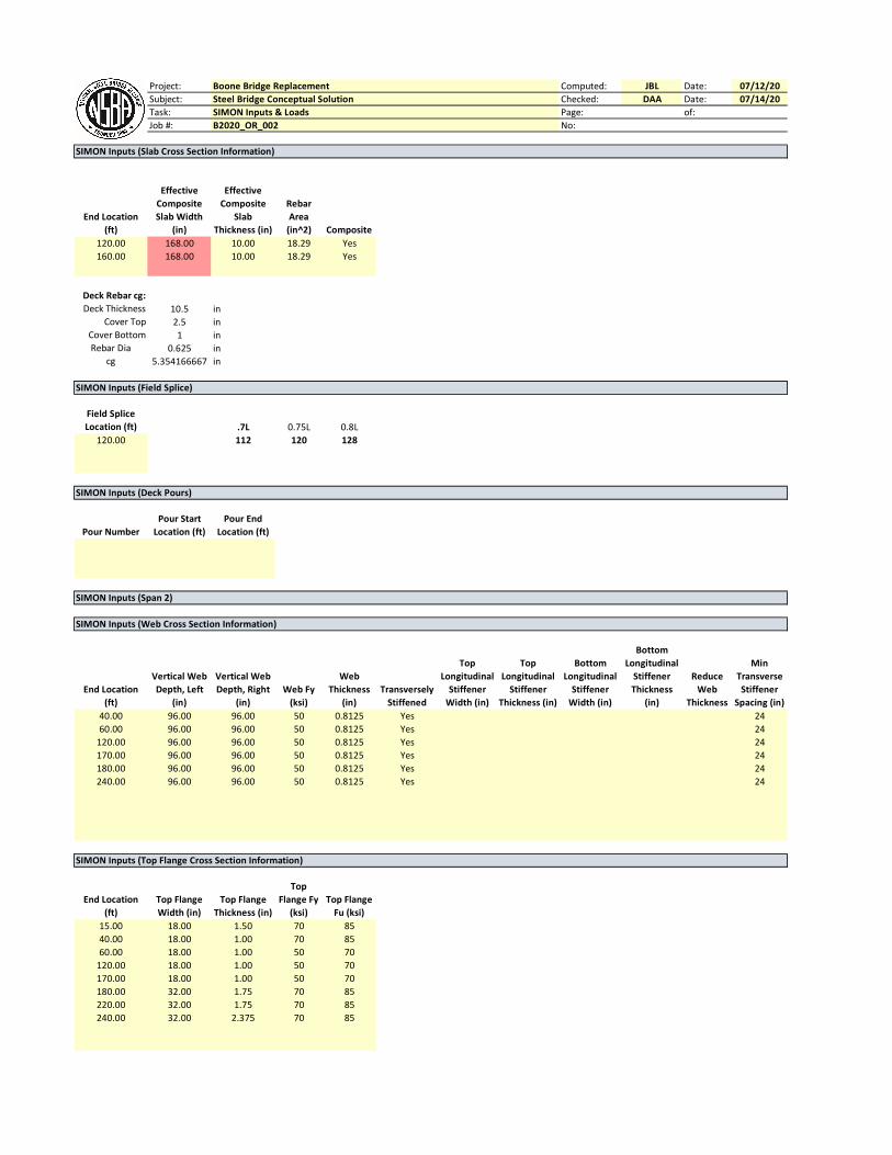
SIMON Inputs (Slab Cross Section Information)
End Location
(ft)
Effective
Composite
Slab Width
(in)
Effective
Composite
Slab
Thickness (in)
Rebar
Area
(in^2) Composite
120.00 168.00 10.00 18.29 Yes
160.00 168.00 10.00 18.29 Yes
Deck Rebar cg:
Deck Thickness 10.5 in
Cover Top 2.5 in
Cover Bottom 1 in
Rebar Dia 0.625 in
cg 5.354166667 in
SIMON Inputs (Field Splice)
Field Splice
Location (ft) .7L 0.75L 0.8L
120.00 112 120 128
SIMON Inputs (Deck Pours)
Pour Number
Pour Start
Location (ft)
Pour End
Location (ft)
SIMON Inputs (Span 2)
SIMON Inputs (Web Cross Section Information)
End Location
(ft)
Vertical Web
Depth, Left
(in)
Vertical Web
Depth, Right
(in)
Web Fy
(ksi)
Web
Thickness
(in)
Transversely
Stiffened
Top
Longitudinal
Stiffener
Width (in)
Top
Longitudinal
Stiffener
Thickness (in)
Bottom
Longitudinal
Stiffener
Width (in)
Bottom
Longitudinal
Stiffener
Thickness
(in)
Reduce
Web
Thickness
Min
Transverse
Stiffener
Spacing (in)
40.00 96.00 96.00 50 0.8125 Yes 24
60.00 96.00 96.00 50 0.8125 Yes 24
120.00 96.00 96.00 50 0.8125 Yes 24
170.00 96.00 96.00 50 0.8125 Yes 24
180.00 96.00 96.00 50 0.8125 Yes 24
240.00 96.00 96.00 50 0.8125 Yes 24
SIMON Inputs (Top Flange Cross Section Information)
End Location
(ft)
Top Flange
Width (in)
Top Flange
Thickness (in)
Top
Flange Fy
(ksi)
Top Flange
Fu (ksi)
15.00 18.00 1.50 70 85
40.00 18.00 1.00 70 85
60.00 18.00 1.00 50 70
120.00 18.00 1.00 50 70
170.00 18.00 1.00 50 70
180.00 32.00 1.75 70 85
220.00 32.00 1.75 70 85
240.00 32.00 2.375 70 85
Project: Boone Bridge Replacement Computed: JBL Date: 07/12/20
Subject: Steel Bridge Conceptual Solution Checked: DAA Date: 07/14/20
Task: SIMON Inputs & Loads Page: of:
Job #: B2020_OR_002 No:
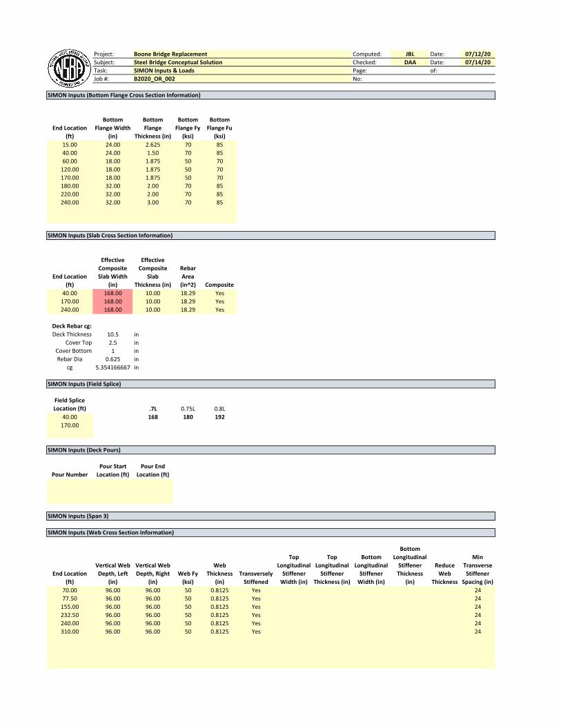
SIMON Inputs (Bottom Flange Cross Section Information)
End Location
(ft)
Bottom
Flange Width
(in)
Bottom
Flange
Thickness (in)
Bottom
Flange Fy
(ksi)
Bottom
Flange Fu
(ksi)
15.00 24.00 2.625 70 85
40.00 24.00 1.50 70 85
60.00 18.00 1.875 50 70
120.00 18.00 1.875 50 70
170.00 18.00 1.875 50 70
180.00 32.00 2.00 70 85
220.00 32.00 2.00 70 85
240.00 32.00 3.00 70 85
SIMON Inputs (Slab Cross Section Information)
End Location
(ft)
Effective
Composite
Slab Width
(in)
Effective
Composite
Slab
Thickness (in)
Rebar
Area
(in^2) Composite
40.00 168.00 10.00 18.29 Yes
170.00 168.00 10.00 18.29 Yes
240.00 168.00 10.00 18.29 Yes
Deck Rebar cg:
Deck Thickness 10.5 in
Cover Top 2.5 in
Cover Bottom 1 in
Rebar Dia 0.625 in
cg 5.354166667 in
SIMON Inputs (Field Splice)
Field Splice
Location (ft) .7L 0.75L 0.8L
40.00 168 180 192
170.00
SIMON Inputs (Deck Pours)
Pour Number
Pour Start
Location (ft)
Pour End
Location (ft)
SIMON Inputs (Span 3)
SIMON Inputs (Web Cross Section Information)
End Location
(ft)
Vertical Web
Depth, Left
(in)
Vertical Web
Depth, Right
(in)
Web Fy
(ksi)
Web
Thickness
(in)
Transversely
Stiffened
Top
Longitudinal
Stiffener
Width (in)
Top
Longitudinal
Stiffener
Thickness (in)
Bottom
Longitudinal
Stiffener
Width (in)
Bottom
Longitudinal
Stiffener
Thickness
(in)
Reduce
Web
Thickness
Min
Transverse
Stiffener
Spacing (in)
70.00 96.00 96.00 50 0.8125 Yes 24
77.50 96.00 96.00 50 0.8125 Yes 24
155.00 96.00 96.00 50 0.8125 Yes 24
232.50 96.00 96.00 50 0.8125 Yes 24
240.00 96.00 96.00 50 0.8125 Yes 24
310.00 96.00 96.00 50 0.8125 Yes 24

Project: Boone Bridge Replacement Computed: JBL Date: 07/12/20
Subject: Steel Bridge Conceptual Solution Checked: DAA Date: 07/14/20
Task: SIMON Inputs & Loads Page: of:
Job #: B2020_OR_002 No:
SIMON Inputs (Top Flange Cross Section Information)
End Location
(ft)
Top Flange
Width (in)
Top Flange
Thickness (in)
Top
Flange Fy
(ksi)
Top Flange
Fu (ksi)
30.00 32.00 2.375 70 85
80.00 32.00 1.375 70 85
230.00 24.00 1.125 50 70
280.00 32.00 1.375 70 85
310.00 32.00 2.375 70 85
SIMON Inputs (Bottom Flange Cross Section Information)
End Location
(ft)
Bottom
Flange Width
(in)
Bottom
Flange
Thickness (in)
Bottom
Flange Fy
(ksi)
Bottom
Flange Fu
(ksi)
30.00 32.00 3.00 70 85
80.00 32.00 1.50 70 85
230.00 24.00 2.50 50 70
280.00 32.00 1.50 70 85
310.00 32.00 3.00 70 85
SIMON Inputs (Slab Cross Section Information)
End Location
(ft)
Effective
Composite
Slab Width
(in)
Effective
Composite
Slab
Thickness (in)
Rebar
Area
(in^2) Composite
80.00 168.00 10.00 18.29 Yes
230.00 168.00 10.00 18.29 Yes
310.00 168.00 10.00 18.29 Yes
Deck Rebar cg:
Deck Thickness 10.5 in
Cover Top 2.5 in
Cover Bottom 1 in
Rebar Dia 0.625 in
cg 5.354166667 in
SIMON Inputs (Field Splice)
Field Splice
Location (ft) .7L 0.75L 0.8L
80.00 217 232.5 248
230.00
SIMON Inputs (Deck Pours)
Pour Number
Pour Start
Location (ft)
Pour End
Location (ft)


