Page 1
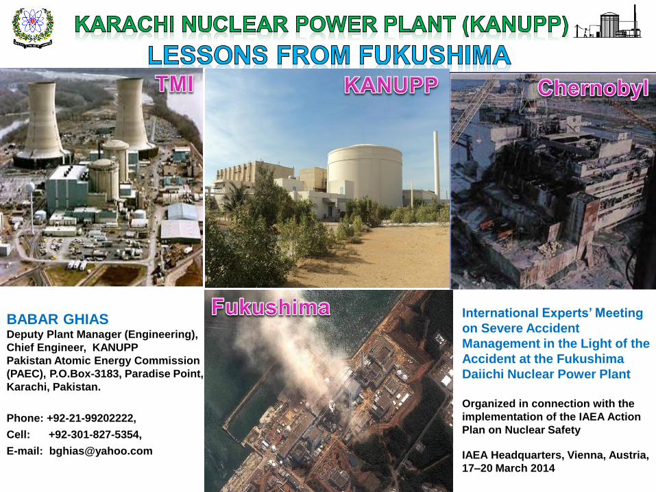
BABAR GHIAS Deputy Plant Manager (Engineering),
Chief Engineer, KANUPP
Pakistan Atomic Energy Commission
(PAEC), P.O.Box-3183, Paradise Point,
Karachi, Pakistan.
Phone: +92-21-99202222,
Cell: +92-301-827-5354,
E-mail: [email protected]
International Experts’ Meeting
on Severe Accident
Management in the Light of the
Accident at the Fukushima
Daiichi Nuclear Power Plant
Organized in connection with the
implementation of the IAEA Action
Plan on Nuclear Safety
IAEA Headquarters, Vienna, Austria,
17–20 March 2014
Page 2
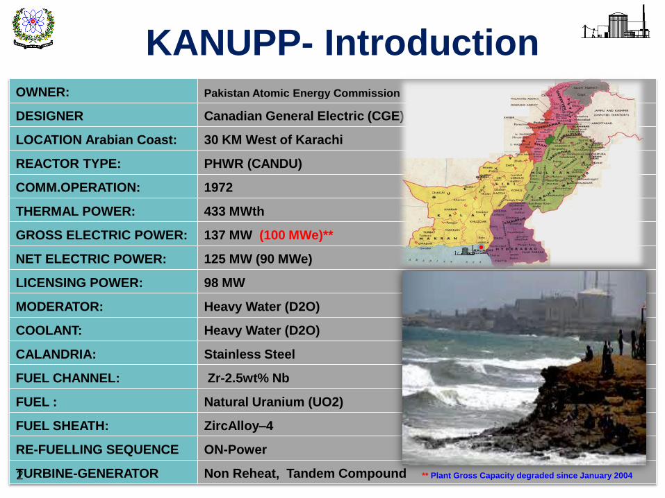
OWNER: Pakistan Atomic Energy Commission
DESIGNER Canadian General Electric (CGE)
LOCATION Arabian Coast: 30 KM West of Karachi
REACTOR TYPE: PHWR (CANDU)
COMM.OPERATION: 1972
THERMAL POWER: 433 MWth
GROSS ELECTRIC POWER: 137 MW (100 MWe)**
NET ELECTRIC POWER: 125 MW (90 MWe)
LICENSING POWER: 98 MW
MODERATOR: Heavy Water (D2O)
COOLANT: Heavy Water (D2O)
CALANDRIA: Stainless Steel
FUEL CHANNEL: Zr-2.5wt% Nb
FUEL : Natural Uranium (UO2)
FUEL SHEATH: ZircAlloy–4
RE-FUELLING SEQUENCE ON-Power
TURBINE-GENERATOR Non Reheat, Tandem Compound
KANUPP- Introduction
2 ** Plant Gross Capacity degraded since January 2004
Page 3
1985 1st IAEA OSART Mission
1989 2nd IAEA OSART Mission
1989 IAEA ASSET Mission
1994 1st WANO Peer Review by TC
1996 WANO-TC Peer Review Follow-Up
1999 IAEA AMAT Mission – Ageing Mgt.
2000 2nd WANO Peer Review by AC
2002 Probabilistic Safety Assessment - Level-1
2006 KFSAR Update Revision-2
2009 Fire - PSA
2010 3rd WANO Special Review by TC
2011 1st PAEC Internal Peer Review (IPR)
2012 KANUPP Safety Assessment
2013 WANO TC Peer Review Follow-up
2013 IPR / FRAP Follow-up
1965 Contract Signed with CGE Canada
1966 Construction Started
1971 First Reactor Criticality Achieved
1971 First Synchronization with the Grid
1972 Inauguration and Commercial Operation
1976 Suspension of Vendor Support
1977 Parts Manufacturing set up
1980 First Pakistani Fuel Bundle in Core
1989 WANO and COG Membership
2002 Completion of Design Life
2003 First re-licensing outage
2006 Second re-licensing outage
KANUPP – Significant Events Significant Milestones Reviews & Assessments
3
Page 4
Current Status of Nuclear Power
1972 2000 2011 2016 2016 ~ 7 Years
KANUPP-1 CHASNUPP-1 CHASNUPP-2 CHASNUPP-3 CHASNUPP-4 KCPP
137 MW 325 MW 330 MW 340 MW 340 MW 2x1100 MW
PHWR PWR PWR PWR PWR APC1000
Canada China China China China China
K-1 C-1 C-2 C-3 K-2/3
4
Energy Security Plan 2005 = 8,800 MWe till 2030.
Vision 2050 = 40,000 MWe till 2050.
C-4
Page 5
Plant / Unit TMI – 2 Chernobyl - 4 Fukushima-1/2/3/4/5/6
Power (MWe) - Type 960 - PWR 1000 - RBMK 1x460, 4x784, 1x1100 - BWR
Country / Commissioning USA - December, 1978 USSR - March 1984 JAPAN - March 1971-Oct.1978
INES Rating 5 7 7
Event Date – Time March 28, 1979, 04:00 hrs April 26, 1986, 01:23 hrs March 11, 2011,14:46 hrs
Event Internal – affecting single unit Internal – affecting single
unit External– affecting multi units
Cause and nature
Equipment failure and
human error causes reactor
coolant fluid to leak. Partial
core meltdown
Safety bypass. Power surge
during a test causes the
reactor to catch fire and
explode.
Prolonged Station Blackout.
Loss of cooling function as a
result of damage caused by
earthquake and tsunami
Response Cooling pump restored Building sealed off by the
sarcophagus
Injection of sea / fresh water to
core
Containment Integrity
Hydrogen explosion.
Containment provision
prevented public exposure
No containment provision.
Damage to secondary
containment during venting of
primary containment.
Radiation Released (peta -
becquerels) 0.062
5200 - Belarus, Russia,
Ukraine, Franc, Italy affected
770
Death due to nuclear
accident 0 30 - 33 0-3
Long term health effects No Known Thousands of cancer and
radiation death cases Not yet known
Evacuation zone
8 km (pregnant women, pre-
school going children,
voluntary)
30 km (116,000 – 230,000) 20 km (80,000 – 141,000)
5
Fact = 05 Severe Core Damages in last 35 years
Ref: Various Sources
Page 6
6
1st BARRIER: Fuel Matrix
2nd BARRIER: Fuel Cladding
3rd BARRIER: Coolant Boundary
Basic Concept of Design-in-Depth and Lessons Ignored (IAEA – INSAG 10)
1st LEVEL: Maintain Normal Operation (OM)
2nd LEVEL: Control Abnormal Operation (OM)
3rd LEVEL: Control Design Basis Accidents (EOPs)
4th BARRIER: Containment 4th LEVEL: Accident Management Including Containment Protection (SAMGs)
5th LEVEL: Off-site Emergency Response (EDMGs)
Chernobyl
TMI
Fukushima
Chernobyl Fukushima
Human
Response
1st LEVEL: Conservative design and analysis
2nd LEVEL: Detection of failures and surveillance
3rd LEVEL: Engineered safety features and procedures
4th LEVEL: Control of severe plant conditions, accident progressions and mitigation
5th LEVEL: Mitigation of radiological consequences of significant off site releases of radioactive material
Safe
ty M
arg
ins, Q
uality
Assura
nce a
nd
Safe
ty C
ultu
re
Chernobyl No Containment
Fukushima
Human
Response
Human
Response
Page 7
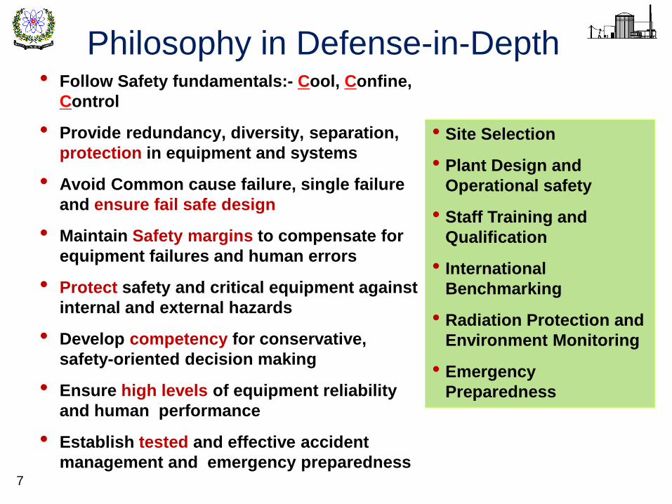
Philosophy in Defense-in-Depth
7
• Follow Safety fundamentals:- Cool, Confine,
Control
• Provide redundancy, diversity, separation,
protection in equipment and systems
• Avoid Common cause failure, single failure
and ensure fail safe design
• Maintain Safety margins to compensate for
equipment failures and human errors
• Protect safety and critical equipment against
internal and external hazards
• Develop competency for conservative,
safety-oriented decision making
• Ensure high levels of equipment reliability
and human performance
• Establish tested and effective accident
management and emergency preparedness
• Site Selection
• Plant Design and
Operational safety
• Staff Training and
Qualification
• International
Benchmarking
• Radiation Protection and
Environment Monitoring
• Emergency
Preparedness
Page 8
Fukushima in Pictures – Ref: TEPCO
11th March 2011, 9.0 Magnitude Earthquake Followed by Tsunami after about one hour
8
• Alternate to zirconium
based or zircaloy cladding
• Site selection should be
under global assessment
scheme
• Spent fuel storage must be
away from the site
• Having multiple units at one
site needs critical review in
terms of post accident
response and management
• Place larger structures of
hydrodynamic design
towards the ocean and
smaller installations in the
“wake” region behind larger
structures
• Key valves must have
redundant control system
• There shall be multiple
access roads to the plant
and these must be wider
and clear.
• Aged and old
generation plants
should be replaced
• Organizational
structure and
staffing with due
regard to SA’s
• Improved decision
making and
communication
during uncertainty
• Training and
guidelines to face
un-expected
situations. Severe
Accident
Simulators ?
• Maintain containment
structural integrity
(Chernobyl lesson
ignored)
• Effective drills and
exercises to manage long
term post accident
management actions
• Long term station
blackout is reality
• Strong Regulatory
Role
• Measures to restore
public confidence
• No to nuclear power
Page 9
S. No. Lesson from FUKUSHIMA
1 Highly Vulnerable site
2 Location of emergency equipment
3 Prolonged station blackout
4 In-adequate diverse electric supply system
5 Improper communication during emergency
6 Delays in critical actions
7 Lack of training at emergency
8 Delays in outside help or assistance
9 Operator has to take critical decisions
10 Un-expected, complex, stressful conditions
11 In-adequacies in Emergency Preparedness
12 Regulatory, Corporate and Human performance 9
Page 10
10
1. Protect safety and critical equipment
and systems from internal & external
hazards
2. Prepare operator to face challenging
unexpected situations and for critical
decision making
3. Controlled filtered venting of
containment to protect integrity against
internal threats
4. Coordinated, tested and well prepared
emergency preparedness and
management program
Prevent
Accident at
all Cost.
Prepare for
Prolonged
Accident
Management
& Emergency
Preparedness
Page 11
Current Status of FRAP
Description
Main Tasks Studies Actions
# % # % # %
Total 78 - 66 - 370 -
Completed 63 80.77 63 95.45 230 62.16
In progress 15 19.23 03 4.55 140 37.84
11
In response to Fukushima NPPs Accident a targeted action plan
called Fukushima Response Action Plan (FRAP) issued for
KANUPP by Corporate Office on 22 June 2011
FUKUSHIMA Response Action Plan (FRAP)
Plan Prepared 1st Review 2nd Review 3rd Review 4th Review Future Review
Jun 2011 Oct 2011 Jun 2012 Feb 2013 Sep 2013 May 2014
Page 12
1. External Natural Hazards
2. Make-shift AC Power
3. DC Power Capacity
4. Fire Protection and Control
5. Emergency Cooling
6. Hydrogen Hazard
7. Containment Integrity
8. Spent Fuel Cooling
9. EOPs, SAMGs (on-site)
10. Emergency Preparedness
11. Operator Training and Preparedness 12
Actions
Page 13
KANUPP Before FUKUSHIMA Accident
Service Building
FIJW-TK1, 180 ton H2O for 100 min or 1.66 hrs
EL = 120’
P
Sump
EL = 110’
Reactor Building
MH-TK1
EFW-TK1
EFO-TK1 3175 USG
EFO-TK2, 750 USG
FIJW-DG1/DG2
EFO-TK3 240 USG
EFO-TK4 240 USG
N-Boilers S-Boilers
2 x EFW-PPs
400 KW each
150 KW each
For one FIJW-DG for
96 hours
With RFW-TK2 for 36 hrs
Spent Fuel Bay
Ground Level = 138 ft elevation
Distribution Room
220V AC , 24 V DC Batteries
Filters
Arabian Sea
FIJW System
IJW System
MH System
Essential Bus Essential Bus
PHT System
Mean Sea level = 100 ft elevation
Building Spray
Pump House = 109 ft elevation
EFW-DG1/DG2
Core
EFW System
13
DE-DG1 DE-DG2
DE-DG3
Page 14
Service Building
FIJW-TK1, 180 ton H2O for 100 min or 1.66 hrs
EL = 120’
P
Sump
EL = 110’
Reactor Building
MH-TK1
EFW-TK1
EFO-TK1 3175 USG
EFO-TK2, 750 USG
FIJW-DG1/2
EFO-TK3 240 USG
EFO-TK4 240 USG
N-Boilers S-Boilers
2 x EFW-PPs
For one FIJW-DG for
96 hours
With RFW-TK2 for 36 hrs
Spent Fuel Bay
Ground Level = 138 ft elevation
Re-assessment of External Hazards
Maximum Tsunami Wave = 109.31 ft
Distribution Room
220V AC , 24 V DC Batteries
(1):- P
rop
er a
nd
effe
ctiv
e D
rain
ag
e S
ys
tem
(1):- Early Tsunami Warning System (TEWS)
from PMD + Fax Machine in MCR
(2):- FIJW-DGs connection to essential busses
(3):- Power to essential MOVs
(3):- Station emergency lighting
(2):- Mobile DG
(4):- Strengthening of fire fighting capabilities
:-PARs and H2 Analyzer
(7):-
Containment
Max press = 40
psig.
Filters
Filtered Venting System
Overall Concept of KANUPP Response Plan to FUKUSHIMA Accident
(8):- Spent Fuel Cooling
Arabian Sea
FIJW System
IJW System
MH System
(6):- Max H2 =
7% by vol
Essential Bus Essential Bus (3):- Continuous charging of batteries
(5) BYW
(5) FIJW
(5) EFW
(5) VCW
:-Water injection through portable diesel driven pump
(5) DSW
PHT System
Mean Sea level = 100 ft elevation
Building Spray
Fire tender
Pump House = 109 ft elevation
2
3
7
4
2
= Injection Points
(1):- Water tight sluice gates
Core
EFW System
Boiling in 19 days Dry out in 140 days
( 1) Seismic Strengthening of service and turbine buildings
(2):- Fuel oil storage = 9 days
Installed at = ~ 170 ft elevation
(2):- Extended SBO of ~ 11 days can be catered
Long term H2 through
MCCI = 430 kg
Development of external EOPs and SAMGs
Scrubber Tank
Emergency Preparedness
DE-DG4/DG5
EWI-D1/D2
EWI-D1/D2
EWI-D1/D2
EWI-D1/D2
EWI-D1/D2
EFW-DG1/2
DE-DG1 DE-DG2
DE-DG3 DE-DG6
14
1
5
6
8
9
10
Lesson
Page 15
SS Shift Supervisor
SED Site Emergency Director
EMG Emergency Management Group
ESG Emergency Support Group
TRC Technical Support committee
ERT Emergency Response Team
DOS Directorate of Safety
SPD Strategic plans Division
NEMS Nuclear Emergency Mgt. System
NDMA National Disaster Mgt. Authority
PDMA Provincial Disaster Mgt. Authority
IAEA International Atomic Energy Agency
AECC Alternate Emergency Control Centre
NURESC Nuclear & Radiological Emergency Response Centre
ERCC Emergency Response Coordination Centre
EOC Emergency Operation Centre
RANET Response Assistance Network
NRECC Nuclear & Radiological Response Cord. Centre
KANUPP Severe Accident Emergency Response & Coordination Plan
15
International
Natio
nal
Member
(Power)
DOS
PAEC - HQ
NRECC,
PNRA -HQ
PNRA
(RNSD-III)
Chairman
(PAEC)
NURESC
(NEMS)
IAEA
(RANET)
NDMA
ECC
AECC
ERCC,
PAEC HQ
SPD Government of Pakistan
KRERC
(EOC)
SED
ESG
EMG
TSC ERT
Media
Provincial PAZ – 400 m
UPZ – 5 km
FRR – 10 km
PDMA Sindh Precautionary
Action Zone
Food Restriction Radius
Urgent Planning Zone
Overs
ight C
om
mitte
e
HAAT
AST
RAG
SLG
RMAT
HAAT = hazard Assess & Advisory Team
AST = Aerial Survey Team
RAG = Radiological Assistance Groups
SLG = Security and Liaison Groups
RMAT = Radiation Medical Asst Team
Page 16
16
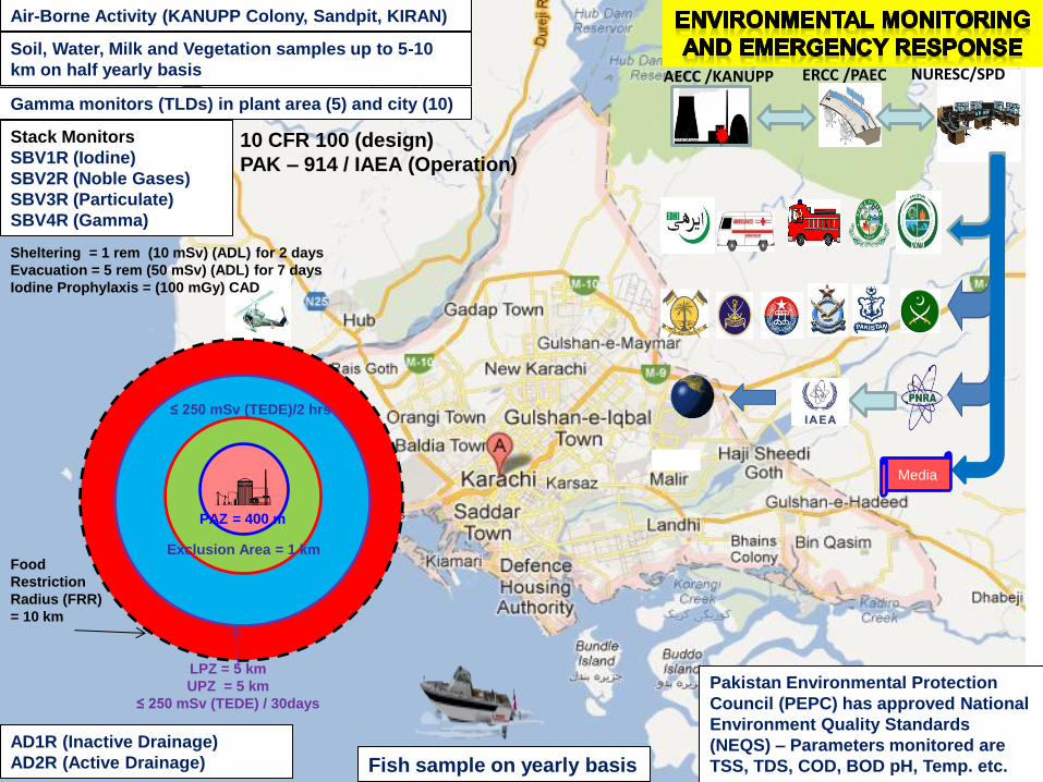
Air-Borne Activity (KANUPP Colony, Sandpit, KIRAN)
Fish sample on yearly basis
Soil, Water, Milk and Vegetation samples up to 5-10
km on half yearly basis
Gamma monitors (TLDs) in plant area (5) and city (10)
Stack Monitors
SBV1R (Iodine)
SBV2R (Noble Gases)
SBV3R (Particulate)
SBV4R (Gamma)
AD1R (Inactive Drainage)
AD2R (Active Drainage)
Pakistan Environmental Protection
Council (PEPC) has approved National
Environment Quality Standards
(NEQS) – Parameters monitored are
TSS, TDS, COD, BOD pH, Temp. etc.
ERCC /PAEC NURESC/SPD AECC /KANUPP
Media
10 CFR 100 (design)
PAK – 914 / IAEA (Operation)
Exclusion Area = 1 km
≤ 250 mSv (TEDE)/2 hrs
Food
Restriction
Radius (FRR)
= 10 km
LPZ = 5 km
UPZ = 5 km
≤ 250 mSv (TEDE) / 30days
PAZ = 400 m
Sheltering = 1 rem (10 mSv) (ADL) for 2 days
Evacuation = 5 rem (50 mSv) (ADL) for 7 days
Iodine Prophylaxis = (100 mGy) CAD
Page 17
Human Error Prevention Tools
Care Situation
Awareness Procedure Checks Verification
Operational
Barriers
Care Enough
to Act Questioning
Attitude
STOP When
Unsure
Task
Preview
Pre-Job
Brief
Job site
Review
Post-Job
Review
Turn over
Procedure
use
Procedure
Adherence
Proc. Deviation
Approval
Place
Keeping
Effective Verbal
Communication
Phonetic
Alphabets
3-Way
Communication
Independent
Verification
Self Check
Peer Check
First Check
Concurrent
Verification
Flagging
Blocking
Fundamental Tool
Conditional Tool OOPS
Verbal
Communication
Verbal Comm.: To ensure understanding between sender and receiver
Phonetic Alphabets: To eliminate confusion regarding letter of referred alphabet
3-Way Comm.: To ensure reliable transfer of information & understanding
First Check: To ensure proper equipment is to be manipulated
Self Check : To focus attention on the task, keeping in mind STAR
Peer Check: To prevent an error by the performer during critical steps
Independent Ver.: To detect an error by the performer involving equipment
Concurrent Ver.: To prevent an error by the performer when doing action
Flagging: To ensure that correct equipment is being manipulated
Blocking: To ensure that incorrect equipment not being manipulated
Care Enough to Act: To take action to improve situation or to prevent harm
Questioning Attitude: To identify gaps between actual and desired situation
Stop When Unsure: To eliminate doubt, uncertainty and confusion
Task Preview: To prepare worker to perform a job right first time
Pre-Job Brief: To understand what to accomplish and what to avoid
Job Site Review: To improve situation awareness when first arriving at site
Post Job Review: To perform self assessment after work for feedback
Turn Over: To orderly transfer work related information to others
Procedure Use: To aware and link directly to procedure classification
Procedure Adherence: To ensure that procedure is understood and followed
Procedure Deviation: To ensure approvals prior to deviating procedure
Place Keeping: To mark steps to avoid repetition and omission
Ref: TG-001-2009
(HEPTOOLS) Operation Division
Stop Think Act Review
Page 18
Stimulus Evidence
MISTAKES (failure to come up with appropriate solution)
SLIPS (right intention incorrectly executed)
LAPSES &
MODE ERRORS (failure to carryout action)
Knowledge Rule Skill
18
Taxonomy of Human error under
unexpected and uncertain situations
Stress, Critical decisions, Uncertainty, In-appropriate resources ?????
Plan intention
of action
Interpretation
Situation
Assessment
Action
Execution
Memory
Page 19
19
•Walk-Through Exercises:- Step by step
review of SAMGs from effectiveness and
practicality
•Table Top Discussions:- Agreement of
all available experience on critical
actions
•Implementation Drills:- Field simulation
exercises from implementation
perspective.
The Key Efforts in KANUPP
Specific Color Coding of FRAP
Related Equipment & Piping
Page 20
20
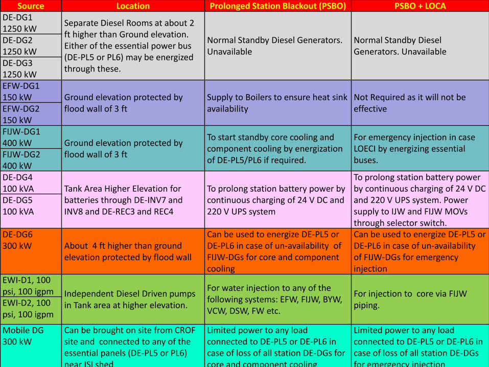
Source Location Prolonged Station Blackout (PSBO) PSBO + LOCA
DE-DG1
1250 kW Separate Diesel Rooms at about 2 ft higher than Ground elevation. Either of the essential power bus (DE-PL5 or PL6) may be energized through these.
Normal Standby Diesel Generators. Unavailable
Normal Standby Diesel Generators. Unavailable
DE-DG2
1250 kW
DE-DG3
1250 kW
EFW-DG1
150 kW Ground elevation protected by flood wall of 3 ft
Supply to Boilers to ensure heat sink availability
Not Required as it will not be effective EFW-DG2
150 kW
FIJW-DG1
400 kW Ground elevation protected by flood wall of 3 ft
To start standby core cooling and component cooling by energization of DE-PL5/PL6 if required.
For emergency injection in case LOECI by energizing essential buses.
FIJW-DG2
400 kW
DE-DG4
100 kVA Tank Area Higher Elevation for batteries through DE-INV7 and INV8 and DE-REC3 and REC4
To prolong station battery power by continuous charging of 24 V DC and 220 V UPS system
To prolong station battery power by continuous charging of 24 V DC and 220 V UPS system. Power supply to IJW and FIJW MOVs through selector switch.
DE-DG5
100 kVA
DE-DG6
300 kW About 4 ft higher than ground elevation protected by flood wall
Can be used to energize DE-PL5 or DE-PL6 in case of un-availability of FIJW-DGs for core and component cooling
Can be used to energize DE-PL5 or DE-PL6 in case of un-availability of FIJW-DGs for emergency injection
EWI-D1, 100 psi, 100 igpm Independent Diesel Driven pumps
in Tank area at higher elevation.
For water injection to any of the following systems: EFW, FIJW, BYW, VCW, DSW, FW etc.
For injection to core via FIJW piping. EWI-D2, 100
psi, 100 igpm
Mobile DG
300 kW
Can be brought on site from CROF site and connected to any of the essential panels (DE-PL5 or PL6) near ISI shed
Limited power to any load connected to DE-PL5 or DE-PL6 in case of loss of all station DE-DGs for core and component cooling
Limited power to any load connected to DE-PL5 or DE-PL6 in case of loss of all station DE-DGs for emergency injection
Page 21
Thank you !
Underground Frozen wall Pipes will carry liquid nitrogen
into the ground freezing the soil
to create a barrier to prevent
ground water from being
contaminated
Impermeable Sea wall A sea wall scheduled for
completion in one year will
attempt to prevent
contaminated water from
flowing into the ocean.
Water Tanks:- Since the disaster
in March 2011, hundreds of tanks
have been built behind the plant to
hold contaminated water. TEPCO
informed that about 270 tons of water
had leaked from one of them.
Page 22
In 1945, the great earthquake of
magnitude 8.3 caused 1.5 m height
tsunami at Karachi harbor (~275
miles from epicenter)
Recent study for assessment of
tsunami hazard for KANUPP
concluded that maximum height of
the wave resulting from the tsunami
would be up to 3.28 ft (~ 01 m)
The heaviest rain fall recorded so
far during last 50 years in a day ~ 10
inches (25.4 cm). The max. rain fall
caused flooding in city but plant
remained unaffected
KANUPP is 39´(~ 12 m) above mean
sea level, quite safe from tsunami.
Distribution room, EDGs, fuel tanks,
ECC DGs and EFW located at
ground level (39 ft above mean sea
level)
1. External Natural Hazard – Tsunami /
Flooding / Earthquake
Back
Page 23
Seismic Retrofits / Anchoring (≥ 0.2g)
Anchoring of DGs Local Panel
Reinforcement of Cable Trays Strengthening of Wall near Bus bar Strengthening of Wall above DG3 bus bar
1. External Natural Hazard - Earthquake
23
Flap and Sliding Gates Back
Page 24
2. Make-Shift Emergency Power Sources
Interconnection scheme of
300 kW DG
Modifications in the
existing system
Installations of
new system Portable Diesel from Outside Agency
Back
Page 25
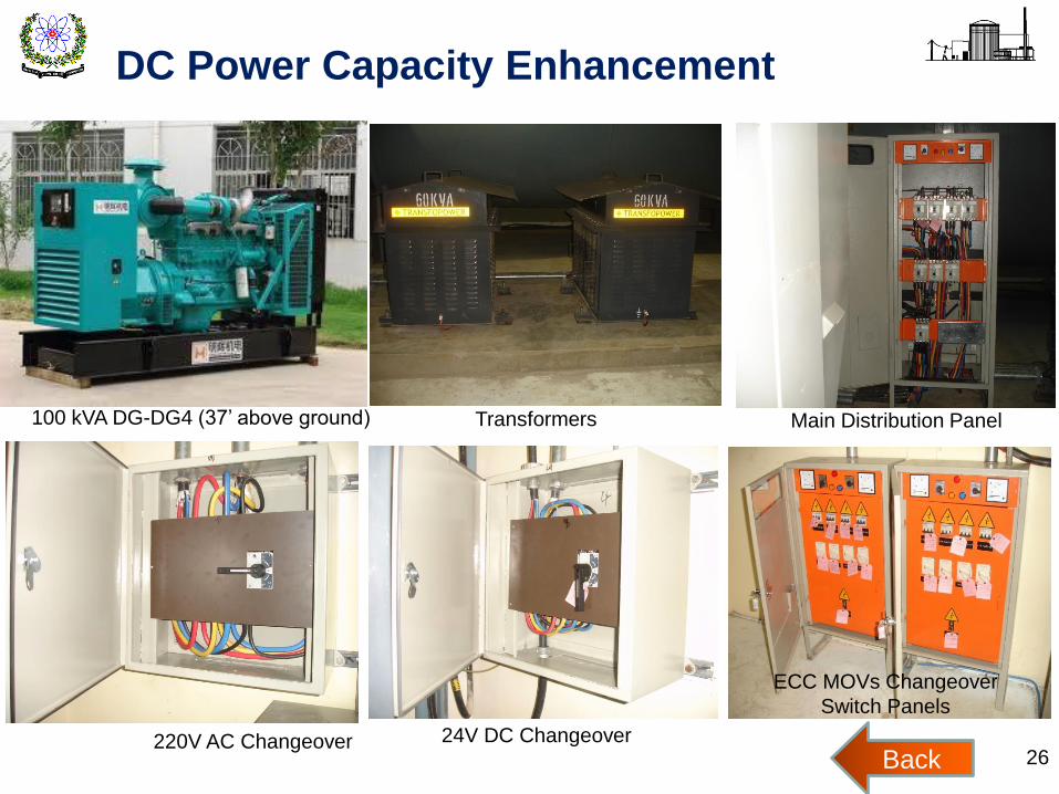
3. DC Power Capacity Enhancement
Preparation of DC conservation
procedure to improve battery
back time of 230V DC from 01 to
07 hrs
Installation of a 100 kVA DG set
and its integration scheme (at
higher elevation, resilience from
earthquake and flooding)
To provide continuous power supply (through 24V DC UPS and 220V AC
UPS systems) to control, monitoring and signaling systems in case of
unavailability of essential power for longer duration
To provide alternate power to ECC MOVs
To supply power to station emergency lighting system
25
Installations of
new systems
Back
Page 26
DC Power Capacity Enhancement
100 kVA DG-DG4 (37’ above ground) Transformers Main Distribution Panel
220V AC Changeover 24V DC Changeover
ECC MOVs Changeover
Switch Panels
26 Back
Page 27
4. Fire Prevention and Control Measures
Refurbishment of Existing Fire Tender
New Fire Tender procured
New Fire Alarm System
• Seismic qualification of fire water ring
• External support for controlling fire emergency
• Strengthening of Fire Fighting Crew
27 Back
Page 28
Additional Measures For Core Cooling (Direct / Indirect)
BFW-TK1
(27740 IG) PW-TK1
(2000 IG)
Spent Fuel Bay
Boilers
Vault Cooling
Core Cooling
FW Ring
Flexible Hose
Dousing Spray
Gravity Feed Line
DMW-TK1
(20000 IG)
SEA
WATER
RFW-TK2
(20000 IG)
~06 days
~01 day
~05+05 days
Diesel Driven Pumps (02)
100 igpm, 100 psi
28
5. Emergency Cooling (EC) Provisions
Installations of
new systems
Back
Page 29
Emergency Core Cooling Measures
Diesel Driven Pump Interconnection with Water Tank
Suction / Discharge Header Piping Layout 29 Back
Page 30
6. Hydrogen Hazard Assessment
Hydrogen hazard assessment study concluds that short
term hydrogen concentration ~ 7% if fuel cladding
material (3128 kg) completely oxidized. Whereas the
calculated value of long term Hydrogen due to MCCI is
430 kg
Installation of Hydrogen Analyzer for monitoring and
Installation of 12 PARs each of 1.2 kg/h capacity for
controlling hydrogen is being done 30
Pressure build up inside
containment, Max Pres = 40 psig
Back
Page 31
CO
NTA
INM
EN
T
Penetr
ation
STA
CK
Ve
nt Ta
nk
Water Storage Tank Feed through pump or gravity
Diesel Driven
Recirculation Pump Drain Valve
(Aliq
uate
336)
(Alk
alin
e s
olu
tio
n
(Thio
sulp
hate
)
Concrete Shielding
Rupture Disk
To Stack
To Dryer
Active
Passive
Orifice
MD8 MD7
MD10 MD9
6”
3”
3”
Containment Filtered Venting System 31
7. Containment Integrity – Filtered Venting
Installations of
new systems
Back
Page 32
8. Spent Fuel Cooling
Estimation of source term of Spent Fuel when water is lost or
configuration is disturbed in Bay
Calculation of dry out times of Spent Fuel Bay ~ 19 days
Measure against loss of cooling or drainage of KANUPP Spent Fuel
Bay ~ 140 days
Design and development of Spent Fuel Dry Storage Facility by 2016
FW Ring
Dry Fuel Storage
Design = 23,760 bundles
+ HDTR = 31, 680
bundles + KSFDS
32 Back
Page 33
9. EOPs, SAMGs (On-Site Actions)
EOPs developed and reviewed by IAEA experts in
2009. In 2010, revised version of EOPs issued after
incorporation of IAEA experts recommendations
In response to Fukushima
SAMGs for external natural hazard and Spent
Fuel Cooling revisited
Validation and verification (V&V) of SAMGs
conducted through tabletop and walkthrough
Revised EOPs. SAMGs issued and training
imparted to operating personnel
33 Back
Page 34
Enhancement for Emergency Preparedness
Gamma Spectrometry System Satellite Phone KI Tablets
Electronic Pocket Dosimeter
Mobile Radiation Monitoring Lab (MRML) 34 Back