Page 1
CLUSTER COMPUTING
A SEMINAR REPORT
Submitted by
KUMAR KAUSHIK
in partial fulfillment of requirement of the Degree
of
Bachelor of Technology (B.Tech)
IN
COMPUTER SCIENCE AND ENGINEERING
SCHOOL OF ENGINEERING
COCHIN UNIVERSITY OF SCIENCE AND TECHNOLOGY
KOCHI- 682022
AUGUST 2008
Page 2
DIVISION OF COMPUTER SCIENCE AND ENGINEERING
SCHOOL OF ENGINEERING
COCHIN UNIVERSITY OF SCIENCE AND TECHNOLOGY
KOCHI-682022
Certificate
Certified that this is a bonafide record of the seminar entitled
“ CLUSTER COMPUTING ”
presented by the following student
KUMAR KAUSHIK
of the VII semester, Computer Science and Engineering in the year 2008 in partial
fulfillment of the requirements in the award of Degree of Bachelor of Technology in
Computer Science and Engineering of Cochin University of Science and Technology.
Ms. Ancy Zachariah Dr. David Peter S.
Seminar Guide Head of Division
Date :
Page 3
Acknowledgement
Many people have contributed to the success of this. Although a single sentence hardly
suffices, I would like to thank Almighty God for blessing us with His grace. I extend my
sincere and heart felt thanks to Dr. David Peter, Head of Division, Computer Science
and Engineering, for providing us the right ambience for carrying out this work. I am
profoundly indebted to my seminar guide, Ms. Ancy Zachariah for innumerable acts of
timely advice, encouragement and I sincerely express my gratitude to her.
I express my immense pleasure and thankfulness to all the teachers and staff of the
Department of Computer Science and Engineering, CUSAT for their cooperation and
support.
Last but not the least, I thank all others, and especially my classmates who in one way or
another helped me in the successful completion of this work.
KUMAR KAUSHIK
Page 4
ABSTRACT
A computer cluster is a group of linked computers, working together
closely so that in many respects they form a single computer. The
components of a cluster are commonly, but not always, connected to each
other through fast local area networks. Clusters are usually deployed to
improve performance and/or availability over that provided by a single
computer, while typically being much more cost-effective than single
computers of comparable speed or availability.
The major objective in the cluster is utilizing a group of processing nodes so
as to complete the assigned job in a minimum amount of time by working
cooperatively. The main and important strategy to achieve such objective is
by transferring the extra loads from busy nodes to idle nodes.
The seminar will contain the concepts of cluster computing and the
principles involved in it.
Page 5
TABLE OF CONTENTS
� ABSTRACT
� LIST OF TABLES
� LIST OF FIGURES
1. INTRODUCTION …………………………………… 1
1.1 GENERAL ……………………………………... 1
1.1.1 Cluster Computing………………………… 1
1.1.2. Cluster Benefits……………………...…… 3
2. Types of Clusters……………………………………... 4
2.1. High Availability or Failover Clusters…….. 4
2.2. Load Balancing Cluster……………………. 6
2.3. Parallel/Distributed Processing Clusters…... 6
3. Cluster Components…………………………………. 8
4. Cluster operation…………………………………….. 11
4.1 Cluster Nodes…………………………………… 11
4.2. Cluster Network………………………………… 12
4.2.1 Network Characterization…………………12
4.2.2 Ethernet, Fast Ethernet, Gigabit Ethernet…13
4.3 Cluster Applications………………………...……13
4.3.1Compute Intensive Applications………13
4.3.2 Data or I/O Intensive Applications……14
4.3.3 Transaction Intensive Applications...…14
4.4 Message Latency…………………………………15
4.5 CPU Utilization……………………….…...……..17
5. Performance Impacts and Care abouts…………………20
5.1 Throughput…………………………………………20
5.1.1 Slow Start……………………………….21
5.1.2 Congestion Avoidance………………….22
6. Cluster Applications……………………………………23
Page 6
6.1 Google Search Engine…………….………….…..23
6.2 Petroleum Reservoir Simulation……….….……..25
6.3 Protein Explorer………………………………….26
6.4 Earthquake Simulation…………………………...28
6.5 Image Rendering……………………………………….30
7. Comparison -Cluster and Grid Computing……………32
8. Summary………………………………………………35
� References…………………………………………36
Page 7
LIST OF TABLES
NO: NAME PAGE
7.1 Cluster and grid 34
LIST OF FIGURES
NO: NAME PAGE
2.1 Failover Cluster 5
2.2 Load Balancing Cluster 6
3 Cluster Components 7
4. 1 Cluster Nodes 8
4.4.1 Message Latency 11
4.4.2 Progression 15
4.4.3 Message Path W/O TOE & RDMA 16
4.4.4 Message Path with TOE & RDMA 17
4.5.1 CPU Utilization 18
4.5.2 Application and Protocol Processing 19
5.1 Throughput 21
6.1 Google Query Architecture 25
6.3 Block Dgm of Protein Explorer S/M 27
6.4 e-Tree method 29
6.5 Visualization of Fire Spread Datasets 31
Page 8
Cluster Computing
Division of Computer Engineering, School of Engineering, CUSAT 1
1.INTRODUCTION
1.1 General Introduction
Parallel computing has seen many changes since the days of the highly expensive and
proprietary super computers. Changes and improvements in performance have also
been seen in the area of mainframe computing for many environments. But these
compute environments may not be the most cost effectiveand flexible solution for a
problem. Over the past decade, cluster technologies have been developed that allow
multiple low cost computers to work in a coordinated fashion to process applications.
The economics, performance and flexibility of compute clusters makes cluster
computing an attractive alternative to centralized computing models and the attendant
to cost, inflexibility, and scalability issues inherent to these models.
Many enterprises are now looking at clusters of high-performance, low cost
computers to provide increased application performance, high availability, and ease of
scaling within the data center. Interest in and deployment of computer clusters has
largely been driven by the increase in the performance of off-the-shelf commodity
computers, high-speed, low-latency network switches and the maturity of the software
components. Application performance continues to be of significant concern for
various entities including governments, military, education, scientific and now
enterprise organizations. This document provides a review of cluster computing, the
various types of clusters and their associated applications. This document is a high-
level informational document; it does not provide details aboutvarious cluster
implementations and applications.
1.1.1 Cluster Computing
Cluster computing is best characterized as the integration of a number of off-the-shelf
commodity computers and resources integrated through hardware, networks, and
software to behave as a single computer. Initially, the terms cluster computing and
high performance computing were viewed as one and the same. However, the
technologies available today have redefined the term cluster computing to extend
beyond parallel computing to incorporate load-balancing clusters (for example, web
Page 9
Cluster Computing
Division of Computer Engineering, School of Engineering, CUSAT 2
clusters) and high availability clusters. Clusters may also be deployed to address load
balancing, parallel processing, systems management, and scalability. Today, clusters
are made up of commodity computers usually restricted to a single switch or group of
interconnected switches operating at Layer 2 and within a single virtual local-area
network (VLAN). Each compute node (computer) may have different characteristics
such as single processor or symmetric multiprocessor design, and access to various
types of storage devices. The underlying network is a dedicated network made up of
high-speed, low-latency switches that may be of a single switch or a hierarchy of
multiple switches.
A growing range of possibilities exists for a cluster interconnection technology.
Different variables will determine the network hardware for the cluster. Price-per-
port, bandwidth, latency, and throughput are key variables. The choice of network
technology depends on a number of factors, including price, performance, and
compatibility with other cluster hardware and system software as well as
communication characteristics of the applications that will use the cluster. Clusters are
not commodities in themselves, although they may be based on commodity hardware.
A number of decisions need to be made (for example, what type of hardware the
nodes run on, which interconnect to use, and which type of switching architecture to
build on) before assembling a cluster range. Each decision will affect the others, and
some will probably be dictated by the intended use of the cluster. Selecting the right
cluster elements involves an understanding of the application and the necessary
resources that include, but are not limited to, storage, throughput, latency, and number
of nodes.
When considering a cluster implementation, there are some basic questions that can
help determine the cluster attributes such that technology options can be evaluated:
1. Will the application be primarily processing a single dataset?
2. Will the application be passing data around or will it generate real-time
information?
3. Is the application 32- or 64-bit?
The answers to these questions will influence the type of CPU, memory architecture,
storage, cluster interconnect, and cluster network design. Cluster applications are
often CPU-bound so that interconnect and storage bandwidth are not limiting factors,
although this is not always the case.
Page 10
Cluster Computing
Division of Computer Engineering, School of Engineering, CUSAT 3
1.1.2 Cluster Benefits
The main benefits of clusters are scalability, availability, and performance. For
scalability, a cluster uses the combined processing power of compute nodes to run
cluster-enabled applications such as a parallel database server at a higher performance
than a single machine can provide. Scaling the cluster's processing power is achieved
by simply adding additional nodes to the cluster. Availability within the cluster is
assured as nodes within the cluster provide backup to each other in the event of a
failure. In high-availability clusters, if a node is taken out of service or fails, the load
is transferred to another node (or nodes) within the cluster. To the user, this operation
is transparent as the applications and data running are also available on the failover
nodes. An additional benefit comes with the existence of a single system image and
the ease of manageability of the cluster. From the users perspective the users sees an
application resource as the provider of services and applications. The user does not
know or care if this resource is a single server, a cluster, or even which node within
the cluster is providing services. These benefits map to needs of today's enterprise
business, education, military and scientific community infrastructures. In summary,
clusters provide:
• Scalable capacity for compute, data, and transaction intensive applications,
including support of mixed workloads
• Horizontal and vertical scalability without downtime
• Ability to handle unexpected peaks in workload
• Central system management of a single systems image
• 24 x 7 availability.
Page 11
Cluster Computing
Division of Computer Engineering, School of Engineering, CUSAT 4
2. TYPES OF CLUSTER
There are several types of clusters, each with specific design goals and functionality.
These clusters range from distributed or parallel clusters for computation intensive or
data intensive applications that are used for protein, seismic, or nuclear modeling to
simple load-balanced clusters.
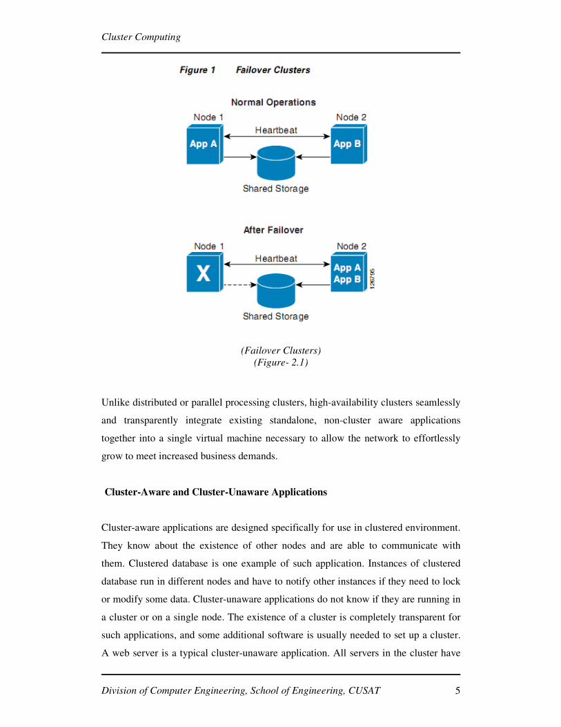
2.1 High Availability or Failover Clusters
These clusters are designed to provide uninterrupted availability of data or services
(typically web services) to the end-user community. The purpose of these clusters is
to ensure that a single instance of an application is only ever running on one cluster
member at a time but if and when that cluster member is no longer available, the
application will failover to another cluster member. With a high-availability cluster,
nodes can be taken out-of-service for maintenance or repairs. Additionally, if a node
fails, the service can be restored without affecting the availability of the services
provided by the cluster (see Figure 2.1). While the application will still be available,
there will be a performance drop due to the missing node.
High-availability clusters implementations are best for mission-critical applications or
databases, mail, file and print, web, or application servers.
Page 12
Cluster Computing
Division of Computer Engineering, School of Engineering, CUSAT 5
(Failover Clusters)
(Figure- 2.1)
Unlike distributed or parallel processing clusters, high-availability clusters seamlessly
and transparently integrate existing standalone, non-cluster aware applications
together into a single virtual machine necessary to allow the network to effortlessly
grow to meet increased business demands.
Cluster-Aware and Cluster-Unaware Applications
Cluster-aware applications are designed specifically for use in clustered environment.
They know about the existence of other nodes and are able to communicate with
them. Clustered database is one example of such application. Instances of clustered
database run in different nodes and have to notify other instances if they need to lock
or modify some data. Cluster-unaware applications do not know if they are running in
a cluster or on a single node. The existence of a cluster is completely transparent for
such applications, and some additional software is usually needed to set up a cluster.
A web server is a typical cluster-unaware application. All servers in the cluster have
Page 13
Cluster Computing
Division of Computer Engineering, School of Engineering, CUSAT 6
the same content, and the client does not care from which server the server provides
the requested content.
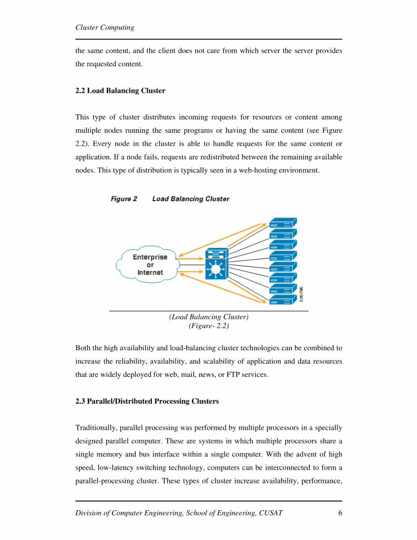
2.2 Load Balancing Cluster
This type of cluster distributes incoming requests for resources or content among
multiple nodes running the same programs or having the same content (see Figure
2.2). Every node in the cluster is able to handle requests for the same content or
application. If a node fails, requests are redistributed between the remaining available
nodes. This type of distribution is typically seen in a web-hosting environment.
(Load Balancing Cluster)
(Figure- 2.2)
Both the high availability and load-balancing cluster technologies can be combined to
increase the reliability, availability, and scalability of application and data resources
that are widely deployed for web, mail, news, or FTP services.
2.3 Parallel/Distributed Processing Clusters
Traditionally, parallel processing was performed by multiple processors in a specially
designed parallel computer. These are systems in which multiple processors share a
single memory and bus interface within a single computer. With the advent of high
speed, low-latency switching technology, computers can be interconnected to form a
parallel-processing cluster. These types of cluster increase availability, performance,
Page 14
Cluster Computing
Division of Computer Engineering, School of Engineering, CUSAT 7
and scalability for applications, particularly computationally or data intensive tasks. A
parallel cluster is a system that uses a number of nodes to simultaneously solve a
specific computational or data-mining task. Unlike the load balancing or high-
availability clusters that distributes requests/tasks to nodes where a node processes the
entire request, a parallel environment will divide the request into multiple sub-tasks
that are distributed to multiple nodes within the cluster for processing. Parallel
clusters are typically used for CPU-intensive analytical applications, such as
mathematical computation, scientific analysis (weather forecasting, seismic analysis,
etc.), and financial data analysis. One of the more common cluster operating systems
is the Beowulf class of clusters. A Beowulf cluster can be defined as a number of
systems whose collective processing capabilities are simultaneously applied to a
specific technical, scientific, or business application. Each individual computer is
referred to as a “node” and each node communicates with other nodes within a cluster
across standard Ethernet technologies (10/100 Mbps, GbE, or 10GbE). Other high-
speed interconnects such as Myrinet, Infiniband, or Quadrics may also be used.
Page 15
Cluster Computing
Division of Computer Engineering, School of Engineering, CUSAT 8
3. CLUSTER COMPONENTS
The basic building blocks of clusters are broken down into multiple categories: the
cluster nodes, cluster operating system, network switching hardware and the
node/switch interconnect (see Figure 3). Significant advances have been
accomplished over the past five years to improve the performance of both
the compute nodes as well as the underlying switching infrastructure.
(Cluster Components)
(Figure- 3)
Application : It includes all the various applications that are going on for a particular
group. These applications run in parallel. These includes various query running on
different nodes of the cluster. This can be said as the input part of the cluster
component.
Middleware: These are software packages which interacts the user with the operating
system for the cluster computing. In other words we can say that these are the layers
of software between applications and operating system. Middleware provides various
Page 16
Cluster Computing
Division of Computer Engineering, School of Engineering, CUSAT 9
services required by an application to function correctly. The software that are used as
middleware are:
OSCAR
Features:
� Image based Installation.
� Supported by Red Hat 9.0 and Mandrake 9.0.
� Processors supported: x86, Itanium (in beta).
� Interconnects: Ethernet, Myrinet.
� Diskless support in development.
� Opteron support in development.
� High-availability support in alpha testing.
SCYLD
Features:
� Commercial distribution.
� Single system image design.
� Processors: x86 and Opteron.
� Interconnects: Ethernet and Infiniband.
� MPI and PVM.
� Diskful and diskless support.
Rocks
Features:
� Processors: x86, Opteron, Itanium.
� Interconnects: Ethernet and Myrinet.
� Compute node management via Red Hat’s kickstart mechanism.
� Diskfull only.
� Cluster on CD.
Operating System: Clusters can be supported by various operating systems which
includes Windows, Linux.etc.
Page 17
Cluster Computing
Division of Computer Engineering, School of Engineering, CUSAT 10
Interconnect: Interconnection between the various nodes of the cluster system can be
done using 10GbE, Myrinet etc. In case of small cluster system these and be
connected with the help of simple switches.
Nodes: Nodes of the cluster system implies about the different computers that are
connected. All of these processors can be of intels or AMD 64 bit.
Page 18
Cluster Computing
Division of Computer Engineering, School of Engineering, CUSAT 11
4. CLUSTER OPERATION
4.1 Cluster Nodes
Node technology has migrated from the conventional tower cases to single rack-unit
multiprocessor systems and blade servers that provide a much higher processor
density within a decreased area. Processor speeds and server architectures have
increased in performance, as well as solutions that provide options for either 32-bit or
64-bit processors systems. Additionally, memory performance as well as hard-disk
access speeds and storage capacities have also increased. It is interesting to note that
even though performance is growing exponentially in some cases, the cost of these
technologies has dropped considerably. As shown in Figure 4.1 below, node
participation in the cluster falls into one of two responsibilities: master (or head) node
and compute (or slave) nodes. The master node is the unique server in cluster systems.
It is responsible for running the file system and also serves as the key system for
clustering middleware to route processes, duties, and monitor the health and status of
each slave node. A compute (or slave) node within a cluster provides the cluster a
computing and data storage capability. These nodes are derived from fully
operational, standalone computers that are typically marketed as desktop or server
systems that, as such, are off-the-shelf commodity systems.
(Cluster Nodes)
(Figure- 4.1)
Page 19
Cluster Computing
Division of Computer Engineering, School of Engineering, CUSAT 12
4.2 Cluster Network
Commodity cluster solutions are viable today due to a number of factors such as the
high performance commodity servers and the availability of high speed, low-latency
network switch technologies that provide the inter-nodal communications.
Commodity clusters typically incorporate one or more dedicated switches to support
communication between the cluster nodes. The speed and type of node interconnects
vary based on the requirements of the application and organization. With today's low
costs per-port for Gigabit Ethernet switches, adoption of 10-Gigabit Ethernet and the
standardization of 10/100/1000 network interfaces on the node hardware, Ethernet
continues to be a leading interconnect technology for many clusters. In addition to
Ethernet, alternative network or interconnect technologies include Myrinet, Quadrics,
and Infiniband that support bandwidths above 1Gbps and end-to-end message
latencies below 10 microseconds (uSec).
4.2.1 Network Characterization
There are two primary characteristics establishing the operational properties of a
network: bandwidth and delay. Bandwidth is measured in millions of bits per second
(Mbps) and/or billions of bits per-second (Gbps). Peak bandwidth is the maximum
amount of data that can be transferred in a single unit of time through a single
connection. Bi-section bandwidth is the total peak bandwidth that can be passed
across a single switch.
Latency is measured in microseconds (µSec) or milliseconds (mSec) and is the time it
takes to move a single packet of information in one port and out of another. For
parallel clusters, latency is measured as the time it takes for a message to be passed
from one processor to another that includes the latency of the interconnecting switch
or switches. The actual latencies observed will vary widely even on a single switch
depending on characteristics such as packet size, switch architecture (centralized
versus distributed), queuing, buffer depths and allocations, and protocol processing at
the nodes.
Page 20
Cluster Computing
Division of Computer Engineering, School of Engineering, CUSAT 13
4.2.2 Ethernet, Fast Ethernet, Gigabit Ethernet and 10-Gigabit Ethernet
Ethernet is the most widely used interconnect technology for local area networking
(LAN). Ethernet as a technology supports speeds varying from 10Mbps to 10 Gbps
and it is successfully deployed and operational within many high-performance cluster
computing environments.
4.3 Cluster Applications
Parallel applications exhibit a wide range of communication behaviors and impose
various requirements on the underlying network. These may be unique to a specific
application, or an application category depending on the requirements of the
computational processes. Some problems require the high bandwidth and low-latency
capabilities of today's low-latency, high throughput switches using 10GbE, Infiniband
or Myrinet. Other application classes perform effectively on commodity clusters and
will not push the bounds of the bandwidth and resources of these same switches.
Many applications and the messaging algorithms used fall in between these two ends
of the spectrum. Currently, there are four primary categories of applications that use
parallel clusters: compute intensive, data or input/output (I/O) intensive, and
transaction intensive. Each of these has its own set of characteristics and associated
network requirements. Each has a different impact on the network as well as how
each is impacted by the architectural characteristics of the underlying network. The
following subsections describe each application types.
4.3.1 Compute Intensive Applications
Compute intensive is a term that applies to any computer application that demands a
lot of computation cycles (for example, scientific applications such as meteorological
prediction). These types of applications are very sensitive to end-to-end message
latency. This latency sensitivity is caused by either the processors having to wait for
instruction messages, or if transmitting results data between nodes takes longer. In
general, the more time spent idle waiting for an instruction or for results data, the
longer it takes to complete the application.
Page 21
Cluster Computing
Division of Computer Engineering, School of Engineering, CUSAT 14
Some compute-intensive applications may also be graphic intensive. Graphic
intensive is a term that applies to any application that demands a lot of computational
cycles where the end result is the delivery of significant information for the
development of graphical output such as ray-tracing applications.
These types of applications are also sensitive to end-to-end message latency. The
longer the processors have to wait for instruction messages or the longer it takes to
send resulting data, the longer it takes to present the graphical representation of the
resulting data.
4.3.2 Data or I/O Intensive Applications
Data intensive is a term that applies to any application that has high demands of
attached storage facilities. Performance of many of these applications is impacted by
the quality of the I/O mechanisms supported by current cluster architectures, the
bandwidth available for network attached storage, and, in some cases, the
performance of the underlying network components at both Layer 2 and 3.
Data-intensive applications can be found in the area of data mining, image processing,
and genome and protein science applications. The movement to parallel I/O systems
continues to occur to improve the I/O performance for many of these applications.
4.3.3 Transaction Intensive Applications
Transaction intensive is a term that applies to any application that has a high-level of
interactive transactions between an application resource and the cluster resources.
Many financial, banking, human resource, and web-based applications fall into this
category.
There are three main care abouts for cluster applications: message latency, CPU
utilization, and throughput. Each of these plays an important part in improving or
impeding application performance. This section describes each of these issues and
their associated impact on application performance.
Page 22
Cluster Computing
Division of Computer Engineering, School of Engineering, CUSAT 15
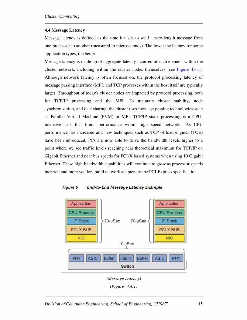
4.4 Message Latency
Message latency is defined as the time it takes to send a zero-length message from
one processor to another (measured in microseconds). The lower the latency for some
application types, the better.
Message latency is made up of aggregate latency incurred at each element within the
cluster network, including within the cluster nodes themselves (see Figure 4.4.1).
Although network latency is often focused on, the protocol processing latency of
message passing interface (MPI) and TCP processes within the host itself are typically
larger. Throughput of today's cluster nodes are impacted by protocol processing, both
for TCP/IP processing and the MPI. To maintain cluster stability, node
synchronization, and data sharing, the cluster uses message passing technologies such
as Parallel Virtual Machine (PVM) or MPI. TCP/IP stack processing is a CPU-
intensive task that limits performance within high speed networks. As CPU
performance has increased and new techniques such as TCP offload engines (TOE)
have been introduced, PCs are now able to drive the bandwidth levels higher to a
point where we see traffic levels reaching near theoretical maximum for TCP/IP on
Gigabit Ethernet and near bus speeds for PCI-X based systems when using 10 Gigabit
Ethernet. These high-bandwidth capabilities will continue to grow as processor speeds
increase and more vendors build network adapters to the PCI-Express specification.
(Message Latency)
(Figure- 4.4.1)
Page 23
Cluster Computing
Division of Computer Engineering, School of Engineering, CUSAT 16
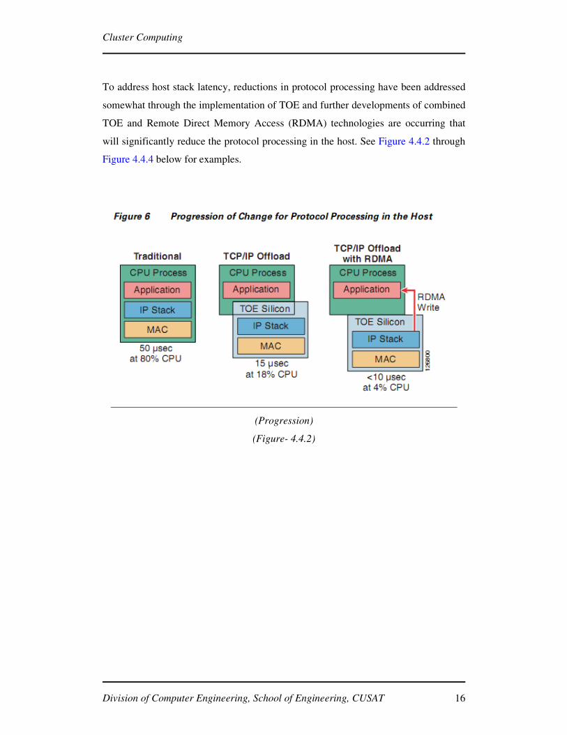
To address host stack latency, reductions in protocol processing have been addressed
somewhat through the implementation of TOE and further developments of combined
TOE and Remote Direct Memory Access (RDMA) technologies are occurring that
will significantly reduce the protocol processing in the host. See Figure 4.4.2 through
Figure 4.4.4 below for examples.
(Progression)
(Figure- 4.4.2)
Page 24
Cluster Computing
Division of Computer Engineering, School of Engineering, CUSAT 17
(Message path Without TOE and RDMA)
(Figure- 4.4.3)
(Message path with TOE and RDMA)
(Figure- 4.4.4)
4.5 CPU Utilization
One important consideration for many enterprises is to use compute resources as
efficiently as possible. As increased number of enterprises move towards realtime and
Page 25
Cluster Computing
Division of Computer Engineering, School of Engineering, CUSAT 18
business-intelligence analysis, using compute resources efficiently is an important
metric. However, in many cases compute resource is underutilized. The more CPU
cycles committed to application processing the less time it takes to run the
application. Unfortunately, although this is a design goal, this is not obtainable as both
the application and protocols compete for CPU cycles.
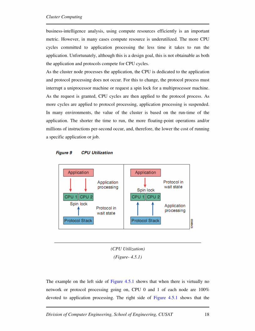
As the cluster node processes the application, the CPU is dedicated to the application
and protocol processing does not occur. For this to change, the protocol process must
interrupt a uniprocessor machine or request a spin lock for a multiprocessor machine.
As the request is granted, CPU cycles are then applied to the protocol process. As
more cycles are applied to protocol processing, application processing is suspended.
In many environments, the value of the cluster is based on the run-time of the
application. The shorter the time to run, the more floating-point operations and/or
millions of instructions per-second occur, and, therefore, the lower the cost of running
a specific application or job.
(CPU Utilization)
(Figure- 4.5.1)
The example on the left side of Figure 4.5.1 shows that when there is virtually no
network or protocol processing going on, CPU 0 and 1 of each node are 100%
devoted to application processing. The right side of Figure 4.5.1 shows that the
Page 26
Cluster Computing
Division of Computer Engineering, School of Engineering, CUSAT 19
network traffic levels have significantly increased. As this happens, the CPU spends
cycles processing the MPI and TCP protocol stacks, including moving data to and
from the wire. This results in a reduced or suspended application processing. With the
increase in protocol processing, note that the utilization percentages of CPU 0 and 1
are dramatically reduced, in some cases to 0.
(Application and Protocol Processing)
(Figure- 4.5.2)
Page 27
Cluster Computing
Division of Computer Engineering, School of Engineering, CUSAT 20
5. PERFORMANCE IMPACTS AND CARE ABOUTS
5.1 Throughput
Data throughput begins with a calculation of a theoretical maximum throughput and
concludes with effective throughput. The effective throughput available between
nodes will always be less than the theoretical maximum. Throughput for cluster nodes
is based on many factors, including the following:
• Total number of nodes running
• Switch architectures
• Forwarding methodologies
• Queuing methodologies
• Buffering depth and allocations
• Noise and errors on the cable plant
As previously noted, parallel applications exhibit a wide range of communication
behaviors and impose various requirements on the underlying network. These
behaviors may be unique to individual applications and the requirements for inter-
processor/inter-nodal communication. The methods used by the application
programmer, as far as the passing of messages using MPI, vary based on the
application requirements. The various MPI message-method gathering methodologies
are show in Figure 5.1 below.
Page 28
Cluster Computing
Division of Computer Engineering, School of Engineering, CUSAT 21
(Throughput)
(Figure- 5.1)
As shown in the examples in Figure 5.1, there are both simple and complex collective
routines. As more scatter-gather, all gather, and all-to-all routines are used, multiple
head-of-line blocking instances may occur within the switch, even within non-
blocking switch architectures. Additionally, the buffer architectures of the underlying
network, specifically the depth and allocation of ingress and egress
buffers, become key to throughput levels. If buffers fill, congestion management
routines may be invoked. In the switch, this means that pause frames will be sent
resulting in the sending node discontinuing sending traffic until the congestion
subsides. In the case of TCP, the congestion avoidance algorithms comes into effect.
5.1.1 Slow Start
In the original implementation of TCP, as soon as a connection was established
between two devices, they could each send segments as fast as they liked as long as
there was room in the other device's receive window. In a busy network, the sudden
appearance of a large amount of new traffic could exacerbate any existing congestion.
Page 29
Cluster Computing
Division of Computer Engineering, School of Engineering, CUSAT 22
To alleviate this problem, modern TCP devices are restrained in the rate at which they
initially send segments. Each sender is at first restricted to sending only an amount of
data equal to one “full-sized”segment that is equal to the MSS value for the
connection. Each time an acknowledgment is received, the amount of data the device
can send is increased by the size of another full-sized segment. Thus, the device
“starts slow” in terms of how much data it can send, with the amount it sends
increasing until either the full window size is reached or congestion is detected on the
link. In the latter case, the congestion avoidance feature, described below, is used.
5.1.2 Congestion Avoidance
When potential congestion is detected on a TCP link, a device responds by throttling
back the rate at which it sends segments. A special algorithm is used that allows the
device to drop the rate at which segments are sent quickly when congestion occurs.
The device then uses the Slow Start algorithm, described above, to gradually increase
the transmission rate back up again to try to maximize throughput without congestion
occurring again.
In the event of packet drops, TCP retransmission algorithms will engage.
Retransmission timeouts can reach delays of up to 200 milliseconds, thereby
significantly impacting throughput.
Page 30
Cluster Computing
Division of Computer Engineering, School of Engineering, CUSAT 23
6. CLUSTER APPLICATIONS
Few important cluster application are:
� Google Search Engine.
� Petroleum Reservoir Simulation.
� Protein Explorer.
� Earthquake Simulation.
� Image Rendering.
6.1 Google Search Engine
Internet search engines enable Internet users to search for information on the Internet
by entering specific keywords. A widely used search engine, Google uses cluster
computing to meet the huge quantity of worldwide search requests that comprise
of a peak of thousands of queries per second. A single Google query needs to use at
least tens of billions of processing cycles and access a few hundred megabytes of data
in order to return satisfactory search results.
Google uses cluster computing as its solution to the high demand of system
resources since clusters have better price-performance ratios than alternative high-
performance computing platforms, and also use less electrical power. Google
focuses on 2 important design factors: reliability and request throughput.
Google is able to achieve reliability at the software level so that a reliable computing
infrastructure can be constructed on clusters of 15,000 commodity PCs distributed
worldwide. The services for Google are also replicated across multiple machines in
the clusters to provide the necessary availability. Google maximizes overall request
throughput by performing parallel execution of individual search requests. This means
that more search requests can be completed within a specific time interval.
Page 31
Cluster Computing
Division of Computer Engineering, School of Engineering, CUSAT 24
A typical Google search consists of the following operations:
1. An Internet user enters a query at the Google webpage.
2. The web browser searches for the Internet Protocol (IP) address via the
www.google.com Domain Name Server (DNS).
3. Google uses a DNS-based load balancing system that maps the query to a
cluster that is geographically nearest to the user so as to minimize network
communication delay time. The IP address of the selected cluster is returned.
4. The web browser then sends the search request in Hypertext Transport Protocol
(HTTP) format to the selected cluster at the specified IP address.
5. The selected cluster then processes the query locally.
6. A hardware-based load balancer in the cluster monitors the available set of
Google Web Servers (GWSs) in the cluster and distributes the requests evenly within
the cluster.
7. A GWS machine receives the request, coordinates the query execution and sends
the search resultback to the user’s browser.
Figure shows how a GWS operates within a local cluster. The first phase of query
execution involves index servers consulting an inverted index that match each query
keyword to a matching list of documents. Relevance scores are also computed for
matching documents so that the search result returned to the user is ordered by score.
In the second phase, document servers fetch each document from disk to extract the
title and the keyword-in-context portion of the document. In addition to the 2
phases, the GWS also activates the spell checker and the ad server. The spell
checker verifies that the spelling of the query keywords is correct, while the ad
server generate advertisements that relate to the query and may therefore interest the
user.
Page 32
Cluster Computing
Division of Computer Engineering, School of Engineering, CUSAT 25
(Google query-serving architecture)
(Figure- 6.1)
6.2 Petroleum Reservoir Simulation
Petroleum reservoir simulation facilitates a better understanding of petroleum
reservoirs that is crucial to better reservoir management and more efficient oil
and gas production. It is an example of GCA as it demands intensive
computations in order to simulate geological and physical models. For example,
The Center for Petroleum and Geosystems Engineering of the University of Texas at
Austin is constructing a new parallel petroleum reservoir simulator called General
Purpose Adaptive Simulator (GPAS) using a cluster of 64 dual-processor servers
with a total of 128 processors.
A typical petroleum reservoir simulator consists of a coupled set of non-linear partial
differential equations and constitutive relations that describe the physical processes
occurring in a petroleum reservoir. There are 2 most widely used simulators. The first
is the black oil simulator that uses water, oil, and gas phases for modeling fluid
flow in a reservoir. The second is the compositional simulator that uses phases
with different chemical species for modeling physical processes occurring in a
reservoir. Previously, compositional simulators were used less often since they
are more complicated and thus require more intensive memory and processing
Page 33
Cluster Computing
Division of Computer Engineering, School of Engineering, CUSAT 26
requirements. With the advent of cluster computing, more researchers are using
compositional simulators that use more data to characterize reservoirs.
The GPAS is a compositional petroleum reservoir simulator that can perform more
accurate, efficient and high-resolution simulation of fluid flow in permeable media.
It uses a finite-difference method which divides a continuous domain into smaller
cells to solve the governing partial differential equations. The higher number of
cells produces more accurate results, but requires more computation time. A fully
implicit solution results in a structure of non-linear equations that are then
resolved using Newton’s method. However, large sparse linear systems of
equations are needed to obtain numerical solution of these non-linear equations.
Therefore, the Portable Extensible Toolkit for Scientific Computation (PETSc), a set
of tools for solving partial differential equations, is used to solve these linear systems.
To handle the parallel processing requirements, an Integrated Parallel Accurate
Reservoir Simulator (IPARS) framework has been developed to separate the
physical model development from parallel processing. IPARS provides input and
output, memory management, domain decomposition, and message passing among
processors to update overlapping regions. Communications between the
simulator framework and a physical model are carried out through FORTRAN
subroutine calls provided within the IPARS, thus hiding the complexities from
the physical model developers who only need to call the FORTRAN subroutines
to perform corresponding tasks.
6.3 Protein Explorer
The Bioinformatics Group at RIKEN Genomic Sciences Center in Japan is currently
building the world-first petaflops supercomputer – the ‘Protein Explorer’ (PE)
system will be a specialized system for molecular dynamics simulations,
specifically, protein simulations, and is expected to be ready in early 2006. The
PE system will be a PC cluster equipped with special-purpose engines to calculate
non-bonded interactions between molecular atoms. These calculations constitute
the most time-consuming portion of the simulations. The PE project is motivated
Page 34
Cluster Computing
Division of Computer Engineering, School of Engineering, CUSAT 27
by the national ‘Protein 3000’ project in Japan that was initiated in 2002 with
the goal of solving the structures of 3,000 proteins by the year 2007.
( Block diagram of Protein Explorer system)
(Figure- 6.3)
Figure shows the components of the PE system. It will be a cluster of 256 dual-
processor nodes giving a total of 512 processors, connected via Gigabit Ethernet.
Each cluster node has 2 special-purpose engine boards (with 12 MDGRAPE-3
chips on each board) connected to it, giving it a total of 6,144 chips.
The cluster nodes will transmit the coordinates and the other data of particles for
the molecular dynamics simulation to the special-purpose engines, which then
calculate the non-bonded forces, such as Coulomb force and van der Walls force
between particles before returning the results to the hosts. In other words, the special-
purpose engines only focus on computing the most complex portion of the
simulation that is calculating the non-bonded forces. All the coordination and
other calculations are handled by the cluster nodes themselves.
Page 35
Cluster Computing
Division of Computer Engineering, School of Engineering, CUSAT 28
6.4 Earthquake Simulation
Earthquake simulation is classified as a GCA given its high modeling and
computational complexities. First, multiple spatial scales characterize the
earthquake source and basin response ranging from tens of kilometers for the
basin dimensions to hundreds of kilometers for earthquake sources. Second,
temporal scales differ from the hundredths of a second for depicting the highest
frequencies of the earthquake source to several minutes of shaking within the basin.
Third, many basins have highly irregular geometry. Fourth, the soils in the basins
comprise heterogeneous material properties. And fifth, there remains great
uncertainty into the modeling process due to the indirect observation of geology and
source parameters.
An ongoing research in the United States focuses on developing the capability for
generating realistic inversion-based models of complex basin geology and earthquake
sources. This capability can then be used to model and forecast strong ground motion
during earthquakes in large basins such as Los Angeles (LA). Ground motion
modeling and forecasting is essential to studying which structures will become
vulnerable during the occurrence of an earthquake. This can be used to design future
earthquake-resistant structures and retrofit existing structures so as to mitigate effects
of an earthquake. The Los Angeles region is chosen as the case study because it is the
most highly populated seismic region in the USA, has well-characterized geological
structures (including a varied fault system), and has extensive records of past
earthquakes.
The earthquake simulation is conducted using a terra-scale HP AlphaServer
cluster which has 750 quadruple-processor nodes at the Pittsburgh
Supercomputing Center (PSC). It simulates the 1994 Northridge earthquake in
the Greater LA Basin at 1 Hz maximum frequency resolution and 100 m/s
minimum shear wave velocity. The resulting unstructured mesh contains over 100
million grid points and 80 million hexahedral finite elements, ranking it as one of
the largest unstructured mesh simulations ever conducted. This is also the most
highly resolved simulation of the Northridge earthquake ever done. It sustains
nearly a teraflops over 12 hours in solving the 300 million wave propagations.
Page 36
Cluster Computing
Division of Computer Engineering, School of Engineering, CUSAT 29
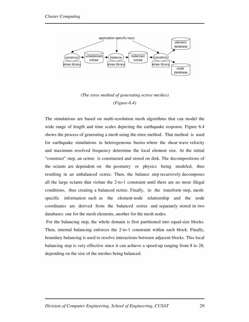
(The etree method of generating octree meshes)
(Figure-6.4)
The simulations are based on multi-resolution mesh algorithms that can model the
wide range of length and time scales depicting the earthquake response. Figure 6.4
shows the process of generating a mesh using the etree method. That method is used
for earthquake simulations in heterogeneous basins where the shear wave velocity
and maximum resolved frequency determine the local element size. At the initial
“construct” step, an octree is constructed and stored on disk. The decompositions of
the octants are dependent on the geometry or physics being modeled, thus
resulting in an unbalanced octree. Then, the balance step recursively decomposes
all the large octants that violate the 2-to-1 constraint until there are no more illegal
conditions, thus creating a balanced octree. Finally, in the transform step, mesh-
specific information such as the element-node relationship and the node
coordinates are derived from the balanced octree and separately stored in two
databases: one for the mesh elements, another for the mesh nodes.
For the balancing step, the whole domain is first partitioned into equal-size blocks.
Then, internal balancing enforces the 2-to-1 constraint within each block. Finally,
boundary balancing is used to resolve interactions between adjacent blocks. This local
balancing step is very effective since it can achieve a speed-up ranging from 8 to 28,
depending on the size of the meshes being balanced.
Page 37
Cluster Computing
Division of Computer Engineering, School of Engineering, CUSAT 30
6.5 Image Rendering
The Scientific Computing and Imaging (SCI) Institute at University of Utah has
explored cluster-based scientific visualization using a 32-node visualization
cluster composed of commodity hardware components connected with a high-
speed network. The OpenGL scientific visualization tool Simian has been modified
to create a cluster-aware version of Simian that supports parallelization by
making explicit use of remote cluster nodes through a message-passing interface
(MPI). Simian is able to generate 3D images for fire-spread simulations that model
scenarios such as when a missile located within a pool of jet fuel catches fire and
explodes. Using image rendering for fire-spread simulations enables researchers to
have a better visualization of the destructive effects.
Normally, Simian uses a swapping mechanism to manage datasets that are too
large to load into the available texture memory, resulting in low performance
and interactivity. For the cluster-aware Simian, large datasets are divided into
sub-volumes that can be distributed across multiple cluster nodes, thus achieving
the interactive performance. This “divide-and-conquer” technique first decomposes
the dataset into sub-volumes before distributing the sub-volumes to multiple remote
cluster nodes. Each node is then responsible for rendering its sub-volume using
the locally available graphics hardware. The individual results are finally
combined using a binary-swap compositing algorithm to generate the final image.
This enables the cluster-aware Simian to visualize large-scale datasets to maintain
interactive rates without the need of texture swapping.Figure shows the
visualization of two fire-spread datasets simulating a heptane pool fire, generated by
the cluster-aware version of Simian using 8 cluster nodes. The top row of Figure
shows two views (side and top views) of the h300_0075 dataset, while the bottom row
shows the h300_0130 dataset.
Page 38
Cluster Computing
Division of Computer Engineering, School of Engineering, CUSAT 31
(Visualization of fire-spread datasets)
(Figure-6.5)
Page 39
Cluster Computing
Division of Computer Engineering, School of Engineering, CUSAT 32
7. Comparison between Cluster Computing and Grid Computing.
The computers (or "nodes") on a cluster are networked in a tightly-coupled fashion--
they are all on the same subnet of the same domain, often networked with very high
bandwidth connections. The nodes are homogeneous; they all use the same hardware,
run the same software, and are generally configured identically. Each node in a
cluster is a dedicated resource--generally only the cluster applications run on a cluster
node. One advantage available to clusters is the Message Passing Interface (MPI)
which is a programming interface that allows the distributed application instances to
communicate with each other and share information. Dedicated hardware, high-speed
interconnects, and MPI provide clusters with the ability to work efficiently on “fine-
grained” parallel problems, including problems with short tasks, some of which may
depend on the results of previous tasks.
In contrast, the nodes on a grid can be loosely-coupled; they may exist across
domains or subnets. The nodes can be heterogeneous; they can include diverse
hardware and software configurations. A grid is a dynamic system that can
accommodate nodes coming in and dropping out over time. This ability to grow and
shrink at need contributes to a grid’s ability to scale applications easily. Grids
typically do not require high-performance interconnects; rather, they usually are
configured to work with existing network connections. As a result, grids are better
suited to relatively “coarse-grained” parallel problems, including problems composed
primarily of independent tasks. There is no dominant programming paradigm in grid
computing today, and a key challenge to increasing the acceptance of grid computing
is creating grid-enabled applications with familiar programming models. Digipede’s
object-oriented programming for grid (OOP-G) is one such model.
Grids can incorporate clusters. Often the best way to make use of all available
resources is to manage the cluster resources as part of a larger grid, assigning jobs and
tasks to the resources best suited to those jobs and tasks. For example, jobs requiring
MPI would be assigned exclusively to the cluster, while loosely-coupled jobs could be
assigned to all grid nodes, including those in the cluster (when available). Indeed,
cluster compute nodes make excellent grid nodes, and many grids are composed
exclusively of dedicated servers. On the Windows operating system compute clusters
are supported by Windows Compute Cluster Server 2003 and grid computing is
Page 40
Cluster Computing
Division of Computer Engineering, School of Engineering, CUSAT 33
supported by the Digipede Network™. The chart below gives an overview of the two
solutions.
Both systems use similar terminology to define submitted requests: A job defines the
work submitted to the system which includes the required resources and the tasks to
execute. A task is an individual unit of work that can be executed concurrently with
other tasks.
Page 41
Cluster Computing
Division of Computer Engineering, School of Engineering, CUSAT 34
(Clusters and Grids)
(Table-7.1)
Page 42
Cluster Computing
Division of Computer Engineering, School of Engineering, CUSAT 35
8. CONCLUSION
High-performance cluster computing is enabling a new class of computationally
intensive applications that are solving problems that were previously cost prohibitive
for many enterprises. The use of commodity computers collaborating to resolve
highly complex, computationally intensive tasks has broad application across several
industry verticals such as chemistry or biology, quantum physics, petroleum
exploration, crash test simulation, CG rendering, and financial risk analysis. However,
cluster computing pushes the limits of server architectures, computing, and network
performance.
Due to the economics of cluster computing and the flexibility and high performance
offered, cluster computing has made its way into the mainstream enterprise data
centers using clusters of various sizes. As clusters become more popular and more
pervasive, careful consideration of the application requirements and what that
translates to in terms of network characteristics becomes critical to the design and
delivery of an optimal and reliable performing solution.
Knowledge of how the application uses the cluster nodes and how the characteristics
of the application impact and are impacted by the underlying network is critically
important. As critical as the selection of the cluster nodes and operating system, so too
are the selection of the node interconnects and underlying cluster network switching
technologies. A scalable and modular networking solution is critical, not only to
provide incremental connectivity but also to provide incremental bandwidth options
as the cluster grows. The ability to use advanced technologies within the same
networking platform, such as 10 Gigabit Ethernet, provides new connectivity options,
increases bandwidth, whilst providing investment protection.
The technologies associated with cluster computing, including host protocol stack-
processing and interconnect technologies, are rapidly evolving to meet the demands of
current, new, and emerging applications. Much progress has been made in the
development of low-latency switches, protocols, and standards that efficiently and
effectively use network hardware components.
Page 43
Cluster Computing
Division of Computer Engineering, School of Engineering, CUSAT 36
REFERENCES
� http://icl.cs.utk.edu/iter-ref
� M. Baker, A. Apon, R. Buyya, H. Jin, “Cluster Computing
and Applications”, Encyclopedia of Computer Science and
Technology, Vol.45, Marcel Dekker, Aug. 2006.
� D. Butenhof, Programming with POSIX Threads,
Addison-Wesley, 2000.
� R. Buyya (ed.), High Performance Cluster Computing:
Systems and Architectures, Prentice Hall, 2007.


![KERALA TECHNOLOGICAL UNIVERSITY - Kerala Gazette technology... · 4th A UG. 2015] KERALA GAZETTE 1271 1. Admission to Bachelor of Technology/B.Tech./B.Tech. (Honours) (a) Eligibility](https://static.documents.pub/doc/80x56/5ad261367f8b9a665f8c6156/kerala-technological-university-kerala-technology4th-a-ug-2015-kerala-gazette.jpg)


