23
| Date post: | 28-Apr-2018 |
| Category: |
Documents |
| Upload: | phamkhuong |
| View: | 227 times |
| Download: | 4 times |

<< Back Home Next >>
2
NOTE
OISD publications are prepared for use in the oil and gas industry under Ministry of Petroleum & Natural Gas. These are the property of Ministry of Petroleum & Natural Gas and shall not be reproduced or copied and loaned or exhibited to others without written consent from OISD. Though every effort has been made to ensure the accuracy and reliability of the data contained in these documents, OISD hereby expressly disclaims any liability or responsibility for loss or damage resulting from their use. These documents are intended to supplement rather than replace the prevailing statutory requirements & best engineering practices in vouge.

3
FOREWORD
The Oil Industry in India is more than 100 years old. As such a variety of practices are in vogue because of collaboration/ association with different foreign companies and governments. Earlier, standardisation in design philosophies, selection, operating and maintenance practices at a national level were hardly in existence. This, coupled with feed back from some serious accidents that occurred in India and abroad, emphasised the need for the industry to review the existing state of art in designing, selecting, operating and maintaining oil and gas installations. With this in view, the then Ministry of Petroleum and Natural Gas in 1986 constituted a Safety Council assisted by Oil Industry Safety Directorate (OISD) staffed from within the industry in formulating and implementing a serious of self-regulatory measures aimed at removing obsolescence, standardising and upgrading the existing standards to ensure safer operations. Accordingly OISD constituted a number of functional committees comprising of experts nominated from the industry to draw up standards and guidelines on various subjects.
The present standard “Selection, Operation & Maintenance Of Pumps” has undergone complete revision by the “Committee for Revision of Standards on Rotary Equipment" in July 2008. This document was originally prepared in July 1990 & amended in August 1999. it is based on the accumulated knowledge and experience of industry members and the various national and international codes and practices and it is meant to be used as a supplement and not as a replacement for existing codes standards and manufacture's recommendations. It is hoped that the provision of this standard, if implemented objectively, may go a long way to improve the safety and reduce accidents in the Oil and Gas Industry. The users of this document are cautioned that no standard can be a substitute for a responsible and experienced engineer. Suggestions are invited from the users after it is put into practice to improve the standard further. Suggestions for amendment, if any, should be addressed to:
The Coordinator Committee for Revision of Standards on Rotary Equipment
Oil Industry Safety Directorate 7th Floor, “New Delhi House”
27, Barakhamba Road New Delhi-110 001
Email id: [email protected] Website www.oisd.gov.in

4
FUNCTIONAL COMMITTEE FOR REVISION OF STANDARDS ON ROTARY EQUIPMENT
(Complete Revision : July, 2008)
List of Members _________________________________________________________________________
Name Organisation Status __________________________________________________________________________ 1. Sh. D.K.Puri Reliance Industries Ltd. Leader 2. Sh. S.K.Chatterjee Hindustan Petroleum Corporation Ltd. Member 3. Sh. Deepak Prabhakar Mangalore Refinery & Petrochemicals Ltd. Member 4. Sh. R.C. Agrawal Bharat Petroleum Corporation Ltd. Member 5. Sh. A.K.Dash Indian Oil Corporation Ltd. Member 6. Sh. K. Ravi Kochi Refineries Ltd. Member 7. Sh. Shamsher Singh Oil Industry Safety Directorate Member 8. Sh. S.K.Sharma Oil Industry Safety Directorate Member Coordinator __________________________________________________________________________

5
SELECTION, OPERATION & MAINTENANCE OF
PUMPS
CONTENT
SECTION DESCRIPTION
1.0 Introduction
2.0 Scope
3.0 Definitions
4.0 Selection / Design of pumps
5.0 Process Control and Protection Systems
6.0 Inspection and Testing
7.0 Erection and Commissioning
8.0 Operation
9.0 Maintenance
10.0 Failure and Root Cause Analysis
11.0 Documentation
12.0 References
ANNEXURE
1. Typical Installation And Test Procedure
2. Typical Preventive Maintenance Schedule

6
SELECTION, OPERATION & MAINTENANCE OF
PUMPS
1.0 INTRODUCTION A pump is a device used to move
liquid fluids or slurries. A pump moves liquids from lower pressure to higher pressure, and overcomes this difference in pressure by adding energy to the system. Pumps work by using mechanical forces to push the material, either by physically lifting, or by the force of compression.
Pumps fall into two major groups:
rotodynamic pumps and positive displacement pumps. Their names describe the method for moving a fluid. Rotodynamic pumps are based on bladed impellers which rotate within the fluid to impart a tangential acceleration to the fluid and a consequent increase in the energy of the fluid. The purpose of the pump is to convert this energy into pressure energy of the fluid to be used in the associated piping system. A positive displacement pump causes a liquid to move by trapping a fixed amount of fluid or gas and then forcing (displacing) that trapped volume into the discharge pipe.
Pumps in Hydrocarbon Industry are
vital & most widely used equipment. Proper selection, operation and maintenance of pumps is a critical factor in overall safety in hydrocarbon industry.
2.0 SCOPE This document covers the safety
aspects in selection, installation & commissioning and operation & maintenance of pumps and their
associated systems in hydrocarbon industry.
3.0 DEFINITIONS 3.1 AXIAL SPLIT PUMPS Pumps with casing joint (principal
casing split joint) parallel to the shaft centerline.
3.2 RADIAL SPLIT PUMPS Pumps with casing joint (principal
casing split joint) perpendicular/normal to the shaft centerline.
3.3 BEST EFFICIENCY POINT (BEP) It is the flow rate at which the pump
achieves its highest efficiency. 3.4 MAXIMUM ALLOWABLE
TEMPERATURE Maximum continuous temperature,
for which the manufacturer has designed the pump (or any part to which the term is referred) when handling the specified fluid at the specified maximum operating pressure.
3.5 MAXIMUM ALLOWABLE
WORKING PRESSURE (MAWP) Maximum continuous pressure, for
which the manufacturer has designed the pump (or any part to which the term is referred) when handling the specified fluid at the specified maximum operating temperature.

7
3.6 MAXIMUM DISCHARGE
PRESSURE Maximum specified suction pressure
plus the maximum differential pressure, which the pump with the furnished impeller is able to develop, when operating at rated speed with fluid of the specified normal relative density (specific gravity).
3.7A MINIMUM CONTINUOUS STABLE
FLOW Lowest flow at which the pump can
operate without exceeding the vibration limits.
3.7B MINIMUM CONTINUOUS
THERMAL FLOW Lowest flow at which the pump can
operate without it’s operation being impaired by the temperature rise of the pumping fluid.
3.8 NET POSITIVE SUCTION HEAD
(NPSH) Total absolute suction pressure
determined at the suction nozzle and referred to the datum elevation, minus the vapour pressure of the liquid, in specified units of head.
3.9 NORMAL OPERATING POINT Point at which the pump is expected
to operate under normal process conditions.
3.10 SUCTION SPECIFIC SPEED Index relating flow, NPSHR and
rotary speed for pumps of similar geometry.
3.11 SHALL Indicates mandatory requirement.
3.12 SHOULD Indicates recommendation or that
which is advised but not mandatory. 4.0 SELECTION / DESIGN OF PUMPS The following factors shall be
considered for selection/ design of Pumps:
a. Media (Fluid) b. Pressure & Temperature c. Hydraulics d. Materials
The pumps shall comply with the applicable equipment standards and OISD standards.
Motors, electrical components and
electrical installations shall be suitable for the area classification as per OISD STD-113 and approved by Chief Controller of Explosives, wherever necessary.
4.1 MEDIA (FLUID)
a. For Hydrocarbon services, the pumps shall conform to applicable API standards or equivalent. b. For Non-Hydrocarbon services, the pumps shall conform to BIS / ISO / ASME or proven vendor standards.
c. Proven special designs can be accepted for services like Fluidized Catalytic Cracker (FCC) Slurry, Molten Sulfur etc.
d. Consideration shall be given in the equipment selection for Toxic, Carcinogenic and Corrosive substances like Hydrogen Sulfide, Amines, Halides and Acids with regard to Materials and Sealing systems.

8
4.2 PRESSURE & TEMPERATURE
a. The Pump casing shall operate without leakage or internal contact between rotating and stationary components. Internal clearances shall be maintained as specified in applicable standard.
b. The casing shall be designed to withstand simultaneously MAWP (Max. Allowable Working Pressure) at corresponding temperature and the worst-case combination of twice the allowable nozzle loads as per applicable standard.
c. In case of Centrifugal Pumps, radial split casings shall be used for any of the following operating conditions:-
i. Pumping temperature of 200 deg. C or higher (a lower temperature limit should be considered if thermal shock is probable).
ii. Flammable or hazardous pumped liquid with a relative density of less than 0.7 at the specified pumping temperature. iii. Flammable or hazardous pumped liquid at a rated discharge pressure above 100 bar.
For applications like pipeline products transfer, feed water etc. pumps designed as per proven vendor standards shall also be acceptable for MAWP of higher than 100 bars.
d. The maximum allowable speed rating for reciprocating pumps shall be as per applicable standard. e. Pulsation suppression shall be provided at the discharge of all metering pumps.
4.3 HYDRAULICS
a. Pumps in other than water service shall have a minimum margin of 0.6
meter between NPSH (Net Positive Suction Head) available and NPSH required. b. Pumps shall be designed for continuous operation at a minimum of 28 deg. C higher than specified maximum operating temperature.
c. Mechanical seals shall be designed for the maximum operating temperature. Provisions of OISD-STD-125 shall be followed for selection and design of mechanical seals. d. Flow dampner and pressure relief valves shall be provided in positive displacement pumps.
4.4 MATERIALS a. The materials for pumps shall be
selected for the specified operating condition and shall be in accordance with the relevant manufacturing standard.
b. Where the process fluid contains
contaminants like H2S, manufacturing process shall require materials and special heat treatment in compliance with NACE MR-103 Standard.
c. The pressure casing shall be
designed with a corrosion allowance to meet the requirement of applicable standard.
4.5 AUXILIARY CONNECTIONS a. For flammable or hazardous
liquids, auxiliary connections to the pressure casing (except the seal gland) shall be socket-welded, butt-welded or integrally flanged. All connection welding shall be completed before the casing is hydrostatically tested.
b. Connections welded to the casing shall meet the material requirements of the casing, including impact values, rather than the requirements

9
of the connected piping. All connection welding shall be completed before the casing is hydrostatically tested.
c. All connections shall be suitable for the hydrostatic test pressure of the region of the casing to which they are attached.
d. All pumps shall be provided with vent and drain connections, except for the pumps having self-venting arrangement.
e. Casing vents and drains shall be
routed to safe location, and double block valves shall be provided for pumps in Hydrocarbon service.
4.6 COUPLING AND GUARDS a. Coupling shall conform to the
relevant nation/ international coupling standard, OISD standard and proven vendor standard.
b. Unless otherwise specified coupling shall be flexible element type. Coupling hubs shall be made of steel and flexible disks shall be made from corrosion resistant material.
c. Coupling shall be rated for at
least maximum driver power, including any service factor.
d. Removable Coupling guards
made from non-sparking material shall be provided.
e. Couplings guards shall enclose
the coupling and the shafts to prevent personnel from contacting moving parts during operation of equipment train.
f. Couplings shall be provided with
a guard capable of withstanding foreseeable external impact.
4.7 STRAINERS
Strainers shall be designed for a minimum delta pressure across the strainer of 1.0 kg/cm2.
Pump suction strainer usage is to
be reviewed for type of operation. Mesh sizing is to be determined considering type/quality of pumping media.
4.8 MECHANICAL SHAFT SEALS The mechanical shaft seals shall be
as per the guidelines given in OISD-STD-125.
4.9 LUBRICATION In case pressurized lubrication
systems are used, sufficient protection systems such a low lube oil pressure, high lube oil temperature etc. shall be provided. Lubrication provisions as mentioned in OISD-RP-126 shall be followed.
5.0 PROCESS CONTROL AND
PROTECTION SYSTEMS The equipment should be protected
against abnormal process conditions by incorporating protection systems, especially for multistage and high speed pumps.
Following considerations should be given; a. To prevent failures due to low
flow conditions, systems shall be equipped with minimum flow protection or automatic re-circulation valves.
b. The lower and upper limits for critical process parameters like suction pressure, discharge pressure, differential pressure, suction and discharge temperatures, should be identified and necessary alarms and trips to prevent failures as applicable should be provided.
c. Monitoring should be provided
for differential pressure across inlet
10
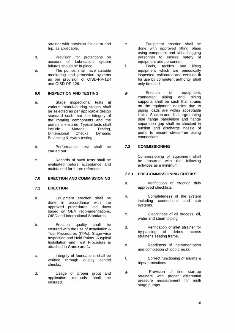
strainer with provision for alarm and trip, as applicable.
d. Provision for protections on
account of Lubrication system failures should be in place.
e. The pumps shall have suitable monitoring and protection systems as per provision of OISD-RP-124 and OISD-RP-126.
6.0 INSPECTION AND TESTING a. Stage inspections/ tests at
various manufacturing stages shall be selected as per applicable design standard such that the integrity of the rotating components and the pumps is ensured. Typical tests shall include Material Testing, Dimensional Checks, Dynamic Balancing & Hydro-testing.
b. Performance test shall be carried out.
c. Records of such tests shall be
evaluated before acceptance and maintained for future reference.
7.0 ERECTION AND COMMISSIONING 7.1 ERECTION a. Equipment erection shall be
done in accordance with the approved procedures laid down based on OEM recommendations, OISD and International Standards.
b. Erection quality shall be ensured with the use of Installation & Test Procedures (ITPs), Stage-wise Inspection and Hold Points. A typical Installation and Test Procedure is attached in Annexure-1.
c. Integrity of foundations shall be
verified through quality control checks.
d. Usage of proper grout and
application methods shall be ensured.
e. Equipment erection shall be done with approved lifting plans using competent and skilled rigging personnel to ensure safety of equipment and personnel.
f. Tools, tackles and lifting equipment which are periodically inspected, calibrated and certified fit for use by competent authority; shall only be used.
g. Erection of equipment, connected piping and piping supports shall be such that strains on the equipment nozzles due to piping loads are within acceptable limits. Suction and discharge mating pipe flange parallelism and flange separation gap shall be checked in suction and discharge nozzle of pump to ensure stress-free piping connections.
7.2 COMMISSIONING Commissioning of equipment shall
be ensured with the following activities as a minimum;
7.2.1 PRE-COMMISSIONING CHECKS a. Verification of erection duly
approved checklists
b. Completeness of the system including connections and sub systems.
c. Cleanliness of all process, oil,
water and steam piping d. Verification of inlet strainer for
by-passing of debris across strainer’s seating frame.
e. Readiness of instrumentation
and completion of loop checks f. Correct functioning of alarms &
trips/ protections g. Provision of fine start-up
strainers with proper differential pressure measurement for multi stage pumps

11
7.2.2 COMPLIANCE WITH; a. Approved Equipment Start-
up Procedure b. Approved Normal Operation
Procedure c. Approved Normal and
Emergency Shutdown Procedures d. Deployment of Qualified,
Trained and Competent personnel. e. Readiness & functional
verification of auxiliary systems like lubrication, cooling and sealing systems.
Equipment shall be commissioned
as per startup procedures and all operating & machine parameters shall be verified for conformity to design values at various steps. Deviations from design values shall be recorded and corrective measures are taken after evaluation.
8.0 OPERATION Safe and reliable operation of
pumps shall be ensured through: a. Use of Standard Operating
Procedures (SOPs). Standard Operating procedures shall address start-up, normal operation and emergency shutdown procedures.
b. Deployment of trained and qualified operators.
c. Periodic training and
validation of operations personnel shall also be carried out.
d. Operation of the equipment
within the specified operating window.
e. Review and verification of all
the protection systems to be in place and functioning. No protections are bypassed except those required to be by-passed for startup after
approval from authorized personnel. (Refer to OISD 126)
f. Continuous monitoring of
process, equipment parameters and condition of auxiliary systems like lubricating oil etc as defined in OISD 124.
g. All ‘Normal, Minimum and
Maximum’ values of operating parameters shall be defined in the procedures or log sheets.
h. Properties of toxic or
hazardous process fluids (MSDS) being handled and the precautions to be taken, shall be prominently displayed near the equipment.
i. Ensure no leaks from oil and
process systems. 9.0 MAINTENANCE 9.1 Maintenance systems in line with
OISD standards shall be in place to ensure the health and integrity of Pumps. Following shall be considered in finalization of the maintenance program;
a. Condition of the equipment b. Type of equipment c. Running hours d. OEM recommendation e. Opportunity
9.2 The maintenance systems should
have the following elements as minimum;
a. Use of Standard
Maintenance Procedures (SMPs) b. Compliance to requirements
like Work Permit Procedure etc. c. Deployment of competent
and skilled personnel validated through training
d. Use of tools, tackles and lifting equipment which are periodically inspected, calibrated & certified fit for use by competent authority

12
e. Procedure shall also be established to carry out monitoring of the equipment and process parameters in line with OISD-RP-124.
f. Procedures shall also detail the type and scope of the Predictive and Preventive activities being done based on standard practices and OISD-RP-124.
g. Typical Preventive Maintenance Schedules for Centrifugal and Positive Displacement Pumps are attached at Annexure-2.
9.3 Procedure shall be in place with
regard to spare parts management. 10.0 FAILURE & ROOT CAUSE
ANALYSIS Failure of pumps shall be analyzed
thoroughly. Root cause shall be established for each premature failure and necessary corrective actions shall be implemented to improve pump reliability. Root cause analysis shall be carried out as per the OISD-RP-126
11.0 DOCUMENTATION Proper documentation system shall
be available to ensure safe operation of rotating equipment.
Documentation shall include the following;
a. Data sheets
b. Performance curves
c. Cross sectional & constructional drawings and relevant P&ID
d. O&M manuals and MRBs e. Commissioning data f. Maintenance History g. Break down/ failure analysis
reports h. Change management
procedures and records Documentation can either be
computerized or as paper documents.
12.0 REFERENCES a. API 610 --Centrifugal Pumps
for Petroleum, Petrochemical & Natural Gas Industries.
b. API 686 – Recommended Practices for Machinery Installation and Installation Design.
c. API 674 – Positive Displacement Pumps - Reciprocating
d. API 675 – Positive Displacement Pumps – Controlled volume
e. API 676 – Positive Displacement Pumps - Rotary
f. API 681 – Liquid Ring Vacuum Pumps & Compressors for Petroleum, Chemical & Gas Industry Services.
g. API 682 – Shaft Sealing System for Pumps
h. API 685 – Seal-less Centrifugal Pumps for Petroleum, Heavy Duty Chemical & Gas Industry Services.
i. API 671 – Special Purpose Couplings for Refinery Service.

13

14
ANNEXURE-1
TYPICAL INSTALLATION AND TEST PROCEDURE
S. N Activity Description Controlling Document
Accept-ance Criteria
Contr-actor
Execut-ing Engi-Neer
QualIty Engi-Neer
1.0 Foundation or structure released for equipment erection.
Document Review
H W DR
2.0 Centerline and elevation marked on foundation. (Incl. Coordinates) and Micro chipping of foundation
G A drawing and Civil drawing
H W W
3.0 Base plate leveling and position - foundation bolts tight
As per Vendors
Installation Manual
Level and shim within specified tolerance.
H W S
4.0 Nozzles and all openings covered/blinded/plugged
Visual W W% S
5.0 Equipment erected with driver and aligned with Foundation centerlines.
G A Drawing
Visual W W% S
6.0 Preliminary leveling alignment of Pump & gearbox, gearbox to Motor Completed and released for grouting.
As per Vendor install.
Manual.
Visual H H W%
7.0 Check grout fills and vent holes. And pocket dimensions checked.
Visual W S S
8.0 Final alignment and leveling of Pump.
Vendor Install
Manual
Reverse dial gauge method.
H W H
9.0 Availability of shims(2-3 mm) under driver and driven equipment
Visual W S S
10.0 Pocket grouting completed.(Remove jack screws after grout is cured)
As per Vendor install.
Manual.
Visual H W% W
11.0 Full grouting of base plate with specified grouting and bolt tightening after complete curing of grout.
Vendor Manual
W W% S
12.0 Check Connection of Pipe work to Equipment nozzles.
Vendor Install
Manual
Flange conc. and
parallel
W W%

15
S. N Activity Description Controlling Document
Accept-ance Criteria
Contr-actor
Execut-ing Engi-Neer
QualIty Engi-Neer
13.0 Erection of all instruments.
Panels, Pressure gauge/switches, Temporary gauge/switches, Orifices, Level gauges/switches/sight glass, Limit switches (if any), Control valve Tubing and Flow meters.
P & ID Visual W S W%
14.0 Check availability/installation of nameplate on pump and motor, Directional arrows on pump, Motor, Control valve and NRVs.
P.O. Data Sheet / P & ID.
Visual W W% W%
15.0 Equipment Painting / Painting touch up complete.
Visual W W% S
16.0 Check parallelism of suction, discharge piping with pump nozzles and check that no strain is imposed on Pump and final alignment with Piping.
Vendor Install
Manual
W W% H
17.0 Tension of belts checked (if belt driven).
Vendor Install
Manual
Visual W W% S
18.0 Coupling and guards installed. Vendor Install
Manual
Visual W W% S
19.0 Lube oil tank clean before first fill.
Vendor Install
Manual
Visual H W% W
20.0 Lube oil system installed and filled with proper lubricant.
Vendor Install
Manual
Visual H W% W
21.0 Check parallelism of suction, discharge piping with pump nozzles and check that no strain is imposed on Pump and Final alignment with piping.
Vendor Install
Manual
W W% H
22.0 Release to insulation Contractor
H W% W%
23.0 Check for free rotation of Shaft.
Vendor Install
Manual
Visual W W% S

16
S. N Activity Description Controlling Document
Accept-ance Criteria
Contr-actor
Execut-ing Engi-Neer
QualIty Engi-Neer
24.0 Erection of auxiliaries, Temporary strainer installed, cooling water piping, safety valves and its calibration, coolers, filters, Flow glass, breather.
As per approved drawing
Visual H W% S
25.0
Temporary packing or seal installed (if permanent packing is not suitable for flushing)
Vendor Install
Manual
Visual W W% S
26.0 Auxiliary Tubing/piping installed.
Vendor Install
Manual
Visual W W% S
27.0 Adjustment of trip and alarm setting.
Vendor Install
Manual
Visual W W% W%
LEGEND OF ANNEXURE-I NO. LEGENDS DESCRIPTION
1 H (Hold Point)
Mandatory inspection point and work shall not proceed without the presence of a representative of the cognizant organization
2 W (Witness Point)
Designated witness points for the involved personnel, which are required to signed off by witnessing personnel. All activities, which have a W point, will require a written notification to Quality / Auditing Engineer, in the event that the quality / audit
3 W% (%Witness Inspection
Point)
Designated percentage witness point assigned by the quality engineer, which will require written notification. In the event quality engineer does not attend within the agreed period, the work may proceed. The percentage shall mean a minimum of 10% inspection.
4 S (Surveillance)
Random observation of the controls of process activities however, such activities are not required to be signed off By the quality engineer
5 DR (Document
Review)
This entails review of appropriate documentation

17
ANNEXURE-2
TYPICAL PREVENTIVE MAINTENANCE SCHEDULE
A. PREVENTIVE MAINTENANCE INSPECTION SCHEDULE FOR CENTRIFUGAL
PUMPS
Centrifugal Pumps are classified in the following groups for the purpose of preparing preventive maintenance schedule:
i) Horizontal Centrifugal Pumps (Both end supported)
ii) Horizontal Centrifugal Pumps (Overhanging type)
iii) Vertical Centrifugal Pumps
iv) Submersible Pumps
A typical preventive maintenance check lists for each type of pump are as given below;
1.0 HORIZONTAL CENTRIFUGAL PUMPS (BOTH END SUPPORTED)
1.1 After 1000 running hours or 3 months which ever is early
i) Bearing lubricant (for water contamination and sediments)
ii) Oil ring for performance
iii) Deflector for looseness
iv) Constant level oiler for leakage
v) Mechanical seal for leakage
vi) Seal flushing/quenching system (of Mechanical Seal) for clogging and chocking.
vii) Gland for leakage
viii) Cooling water flow in both the bearing housings
ix) Condition of bearing by sound and temperature (in running condition)
x) Performance of all measuring instruments (Pressure/Temperature gauges and
Flow Meters)
xi) Coupling Guard
xii) Electric Motor load current
xiii) Axial position indicator (in case of multistage pump)
xiv) Dowel pins (in position or not; wherever provided)
1.2 After 4000 running hours or 1 year which ever is early
i) Repeat all checks per 1.1.
ii) Flushing of bearing with lube oil and refilling of oil to required level, whether
carried out or not
18
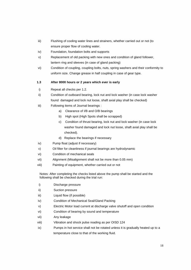
iii) Flushing of cooling water lines and strainers, whether carried out or not (to
ensure proper flow of cooling water.
iv) Foundation, foundation bolts and supports
v) Replacement of old packing with new ones and condition of gland follower,
lantern ring and sleeves (in case of gland packing)
vi) Condition of coupling, coupling bolts, nuts, spring washers and their conformity to
uniform size. Change grease in half coupling in case of gear type.
1.3 After 8000 hours or 2 years which ever is early
i) Repeat all checks per 1.2.
ii) Condition of outboard bearing, lock nut and lock washer (in case lock washer
found damaged and lock nut loose, shaft axial play shall be checked)
iii) Following items of Journal bearings :
a) Clearance of I/B and O/B bearings
b) High spot (High Spots shall be scrapped)
c) Condition of thrust bearing, lock nut and lock washer (in case lock
washer found damaged and lock nut loose, shaft axial play shall be
checked).
d) Replace the bearings if necessary
iv) Pump float (adjust if necessary)
v) Oil filter for cleanliness if journal bearings are hydrodynamic
vi) Condition of mechanical seals
vii) Alignment (Misalignment shall not be more than 0.05 mm)
viii) Painting of equipment, whether carried out or not
Notes: After completing the checks listed above the pump shall be started and the following shall be checked during the trial run:
i) Discharge pressure
ii) Suction pressure
iii) Liquid flow (if possible)
iv) Condition of Mechanical Seal/Gland Packing
v) Electric Motor load current at discharge valve shutoff and open condition
vi) Condition of bearing by sound and temperature
vii) Any leakage
viii) Vibration and shock pulse reading as per OISD 124
ix) Pumps in hot service shall not be rotated unless it is gradually heated up to a
temperature close to that of the working fluid.

19
1.4 After 16000 hours or 4 years which ever is early
Complete overhauling of the pump shall be carried out including all checks specified for 8000 hours.
2.0 HORIZONTAL CENTRIFUGAL PUMPS (OVERHANGING TYPE)
2.1 After 1000 hours or 3 months which ever is early
i) Oil in bearing housing for water contamination and sediment (Replace oil if
necessary)
ii) Oil ring for proper working
iii) Constant level oiler for proper working
iv) Gland packing (for leakage)
v) Condition of Mechanical Seal (OISD RP 125, “Inspection and Maintenance of
Mechanical Seals” shall be referred for replacement)
vi) Cooling water flow
vii) Condition of coupling guard
viii) Condition of bearing by sound and temperature
ix) Electric Motor load current (at discharge valve shutoff and open condition)
x) Performance of all measuring instruments (Pressure/Temperature gauges and
flow meters)
xi) Greasing of bearing; if bearings are grease lubricated Note 3
2.2 After 4000 hours or one year which ever is early
i) Repeat all checks per 4.2.1.
ii) Flushing of cooling water lines and cleaning of Strainers, whether carried out or
not (to ensure proper flow of cooling water)
iii) Condition of coupling (in decoupled condition)
iv) Coupling end support for any abnormality
v) Foundation, foundation bolts and supports.
vi) Alignment (Realign, if necessary)
vii) Performance of all measuring instruments and recording of readings
viii) Suction line strainer for cleanliness
2.3 After 8000 hours or 2 years whichever earlier
Complete overhauling of the pump shall be carried out.
Notes: i) After completing the checks listed above the pump shall be started and
the following shall be checked during the trial run;

20
a) Discharge pressure
b) Suction pressure
c) Liquid flow (if possible)
d) Condition of Mechanical Seal/Gland Packing
e) Electric Motor load current at discharge valve shutoff and open condition
f) Condition of bearing by sound and temperature
g) Any Leakage
h) Vibration and shock pulse reading as per OISD 124
ii) Pumps in hot service shall not be rotated unless it is gradually heated up to a temperature close to that of the working fluid.
3.0 SUBMERSIBLE PUMPS (WET MOTOR TYPE AND DRY MOTOR TYPE)
3.1 After every 250 hours or fortnightly whichever earlier
i) Ensure optimum liquid level to avoid dry run wherever auto cut in/cut out not
provided
ii) Motor load current
iii) Pump discharge pressure
iv) Any abnormal sound and vibration of connected piping
3.2 After every 8000 hrs. or 2 years which ever is early Complete overhauling of the pump shall be carried out. 4.0 VERTICAL CENTRIFUGAL PUMPS
4.1 After 1000 hours or 3 months whichever earlier
i) Oil in bearing housing for water contamination and sediment (Replace oil if
necessary)
ii) Constant level oiler for proper working
iii) Gland packing (for leakage)
iv) Condition of Mechanical Seal (OISD RP 125, “Inspection and Maintenance of
Mechanical seals” shall be referred for replacement)
v) Cooling water flow
vi) Condition of coupling guard
vii) Condition of bearing by sound and temperature
viii) Electric Motor load current (at discharge valve shutoff and open condition)
ix) Performance of all measuring instruments (Pressure/Temperature gauges and
flow meters)

21
4.2 After 4000 hours or 1 year which ever is early:
i) Repeat all checks per 4.1
ii) Flushing of cooling water lines and cleaning of Strainers, whether carried out or
not (to proper flow of cooling water)
iii) Condition of coupling (in decoupled condition)
iv) Foundation, foundation bolts and supports
v) Alignment (Realign, if necessary)
vi) Performance of all measuring instruments and recording of readings
vii) Suction line strainer for cleanliness
4.3 After every 24000 hours or 4 years which ever is early Complete overhauling shall be carried out.
B. PREVENTIVE MAINTENANCE INSPECTION SCHEDULE FOR POSITIVE
DISPLACEMENT PUMPS
Positive displacement pumps are classified in the following groups for preparation of preventive maintenance inspection schedule:
i) Reciprocating Pumps/plunger pump
ii) Gear Pumps/Screw Pumps
A typical preventive maintenance check lists for each type of pump are as given below;
1.0 RECIPROCATING / PLUNGER / DIAPHRAGM PUMPS
1.1 After 1000 Hours
i) Crank case oil condition for contamination
ii) Gear Box oil condition for contamination
iii) Gland for leakage Note 3
iv) Coupling guard condition (shall be rectified if necessary)
v) Motor and Gear box bearings by sound and temperature (in running condition)
vi) Relief valves for passing
vii) Lubricating oil pump and non return valve (for steam driven pump only)
1.2 After 4000 Hours
i) Crank case oil replacement (crankcase shall be flushed before oil replacement)
ii) Gear box oil replacement (gear box shall be flushed before oil replacement).
iii) Condition of piston/plunger and liner for wear

22
iv) Lubricating oil strainer and piping
v) Bearing and Gear of Gear box for any damage
vi) Coupling guard condition
vii) Working of safety relief valve
viii) Ensure replacement of gland packing
ix) Alignment
x) Suction and discharge valve, valve seat etc.
xi) Stroke adjusting mechanism (shall be serviced if necessary)
xii) Lubrication for the steam driven side (in case of stream driven pump)
xiii) Foundation, foundation bolts and supports
Note: After completing the checks listed above the pump shall be started and the following shall be checked during the trial run. a) Vibration and temperature of bearing of Gearbox and Motor
b) Gland for leakage (shall be adjusted if necessary)
c) Pump performance
1.3 After 8000 Hours
Complete overhauling of the pump shall be carried out.
2.0 GEAR PUMPS / SCREW PUMPS
For Gear Pumps/ Screw Pumps/ Dosing Pumps, the inspection schedule shall be fixed depending on the specific nature of application and manufacturer’s recommendation.
2.1 INSPECTION ITEMS OF GEAR PUMPS
The following shall be checked/ recorded: i) Gear Casing
a) Clearance between gear and casing.
b) End clearance between gears and end covers
c) Backlash
ii) Bush/Bearing
a) Clearance between gear shaft and bush.
b) Bearing as per OISD 123
iii) Seal
a) Condition of Seal
b) Replacement of elastomer

<< Back Home Next >>


