22
Background effect to Vertex Detector and Impact parameter resolution T. Fujikawa(Tohoku Univ.) Feb. 4 2005 LC Detector Meeting
| Date post: | 16-Dec-2015 |
| Category: |
Documents |
| Upload: | amanda-scovil |
| View: | 216 times |
| Download: | 0 times |
Background effect to Vertex Detector and Impact parameter resolution
T. Fujikawa(Tohoku Univ.)
Feb. 4 2005 LC Detector Meeting
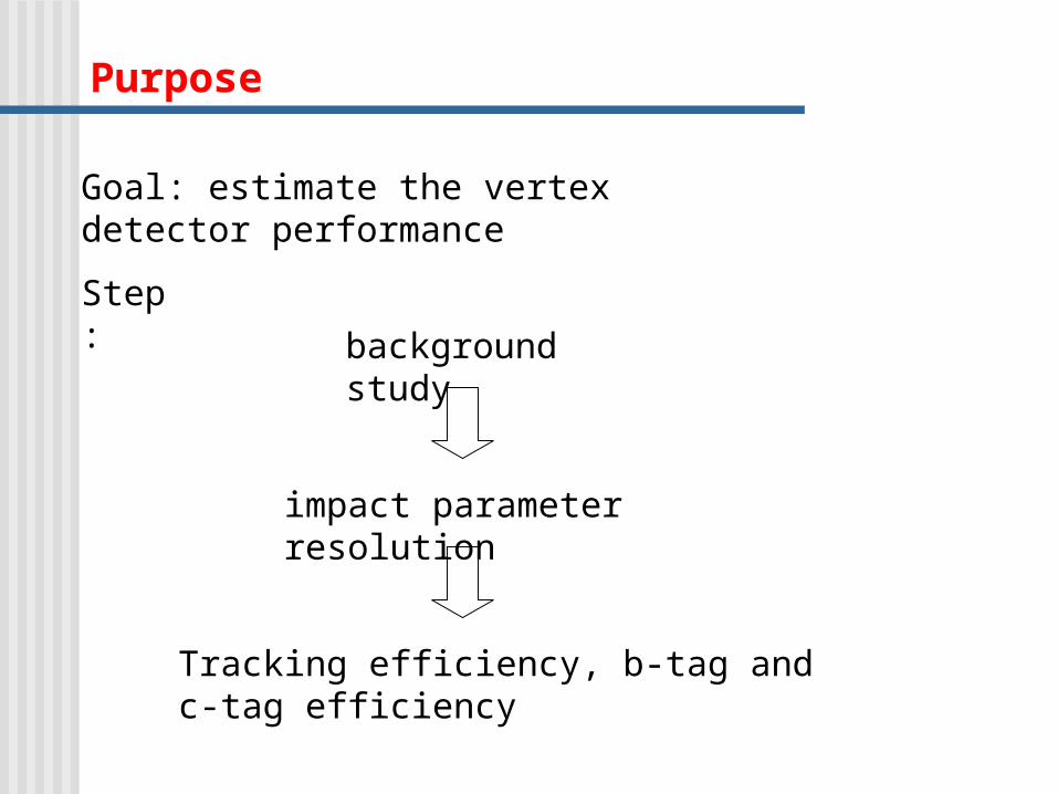
Purpose
Goal: estimate the vertex detector performance
background study
Step:
impact parameter resolution
Tracking efficiency, b-tag and c-tag efficiency
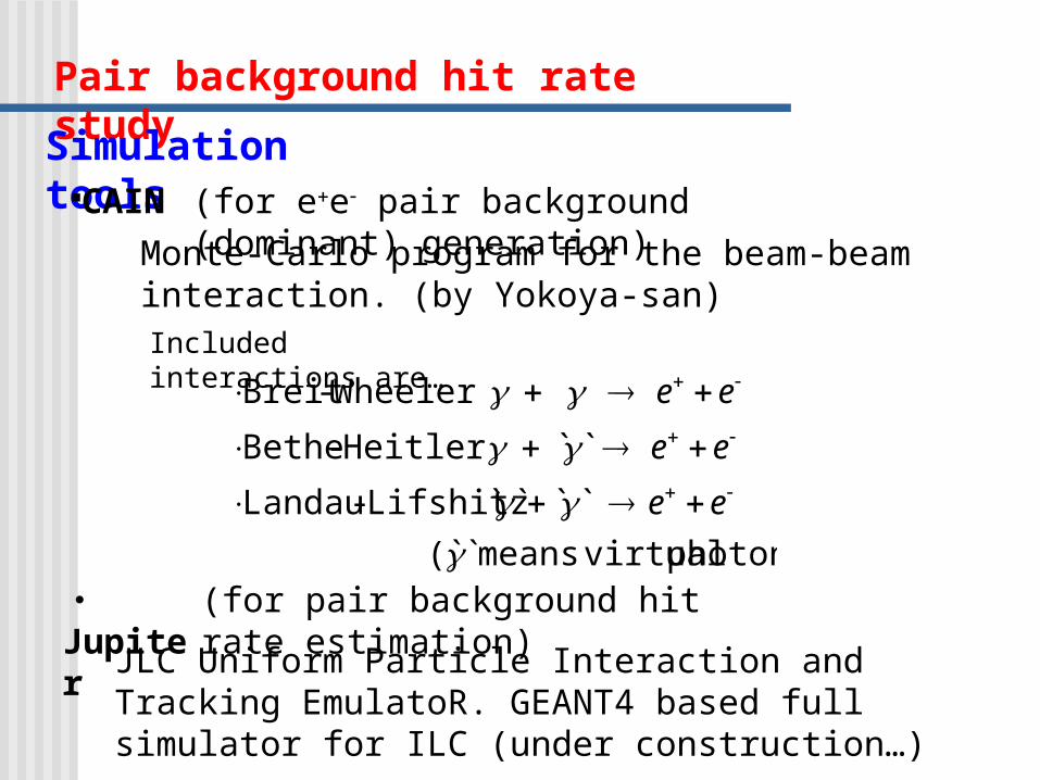
Pair background hit rate study
Simulation tools
Monte-Carlo program for the beam-beam interaction. (by Yokoya-san)Included interactions are…
・JupiterJLC Uniform Particle Interaction and Tracking EmulatoR.
GEANT4 based full simulator for ILC (under construction…)
CAIN
photon) virtualmeans ̀(`
` ̀ ̀` Lifshitz-Landau
`` Heitler -Bethe
Wheeler -Breit
ee
ee
ee
(for ee pair background (dominant) generation)
(for pair background hit rate estimation)

Beam parameters (for the CAIN)
7mrad. angle crossing
)(3.0 ),(5 (553
)(03.0 ,)(10
(/train)2820n (/bunch),102.0 Ne GeV,500E
zyx
yx
b10
CM
mmnmnm),
mm
Beam parameters are mostly the same as the TESLA TDR.
))(/104.3( 234 scmL
In order to obtain the high luminosity, beam focus is set in 250 micron in front of IP, and crab angle is included.
IP = focus
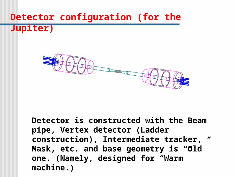
Detector configuration (for the Jupiter)
Detector is constructed with the Beam pipe, Vertex detector (Ladder construction), Intermediate tracker, Mask, etc. and base geometry is “Old” one. (Namely, designed for “Warm” machine.)

The configuration of the vertex detector
These conditions are applied to estimate pair background hit rate as first layer radius is varied.
0.4cm islayer innermost and pipe beambetween distance the
) layers4( 1.2cm islayer each between distance the
300 Thickness
coverd are 9.0|cos|hasch region whi the
m
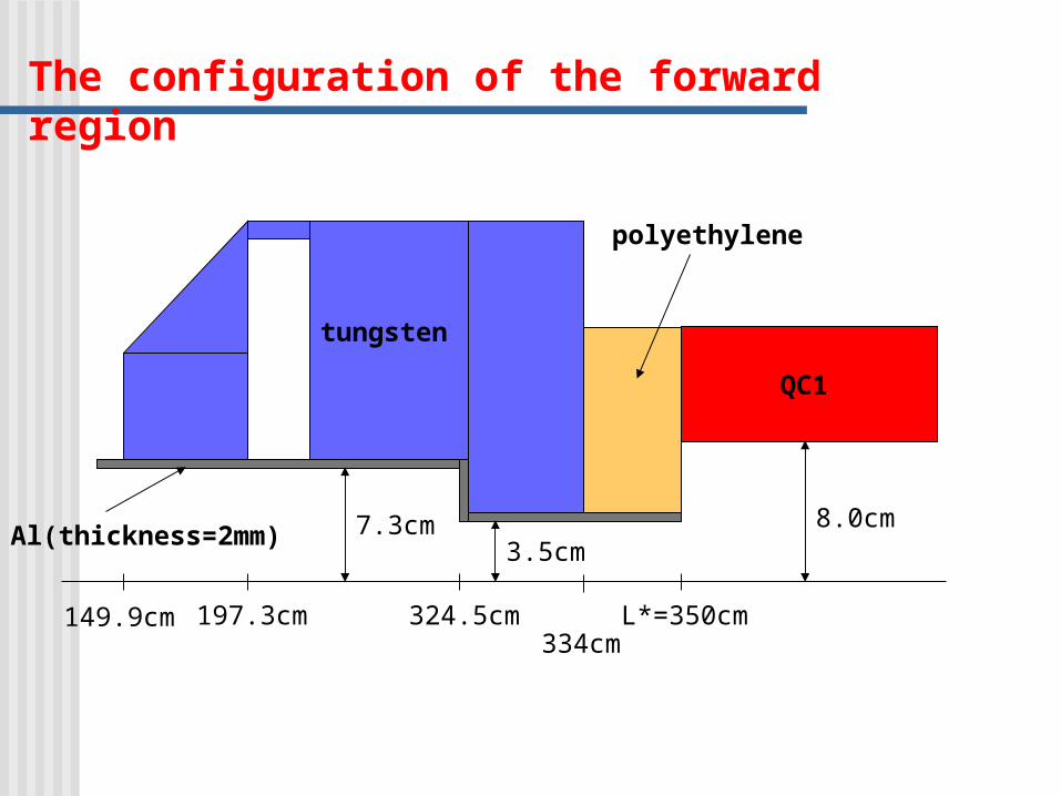
The configuration of the forward region
Al(thickness=2mm)
tungsten
QC1
polyethylene
7.3cm3.5cm
8.0cm
L*=350cm324.5cm197.3cm149.9cm334cm

Pair background hit rate for the vertex detector1.hit point uniformity (for 1st. layer)
We can use the average hit rate to estimate the occupancy.
region. 9.0|cos| within uniform ison distributiHit
Z
0.9 |cos|
B = 3tesla, R1 = 1.2cm.
Phi vs. Z
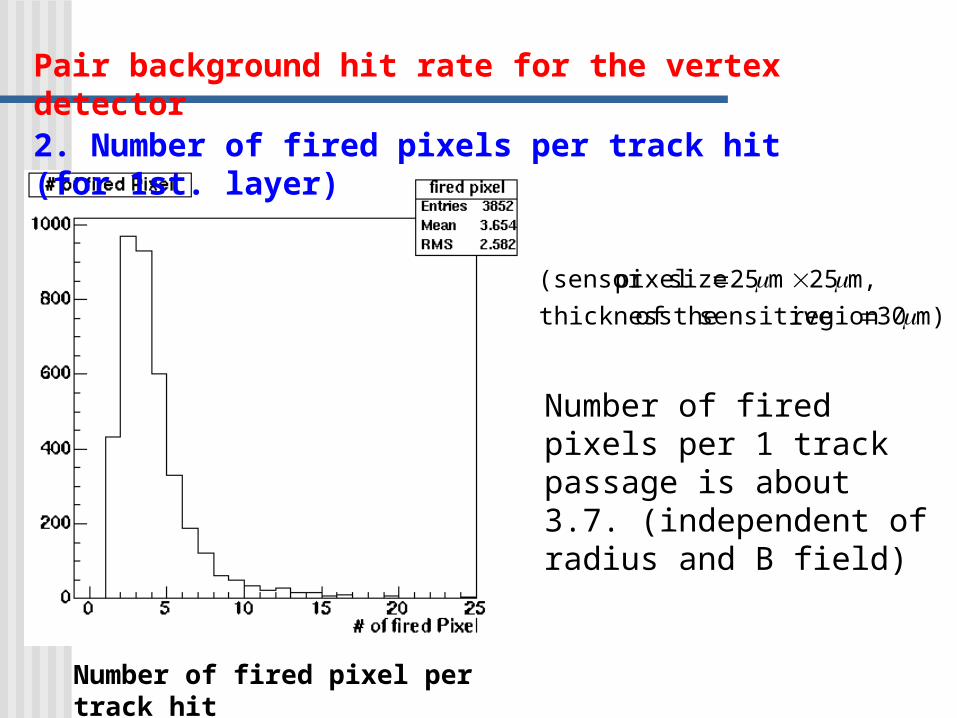
2. Number of fired pixels per track hit (for 1st. layer)
Number of fired pixel per track hit
Number of fired pixels per 1 track passage is about 3.7. (independent of radius and B field)
m)30 region sensitive theof thickness
m,25 m25 size pixel(sensor
Pair background hit rate for the vertex detector
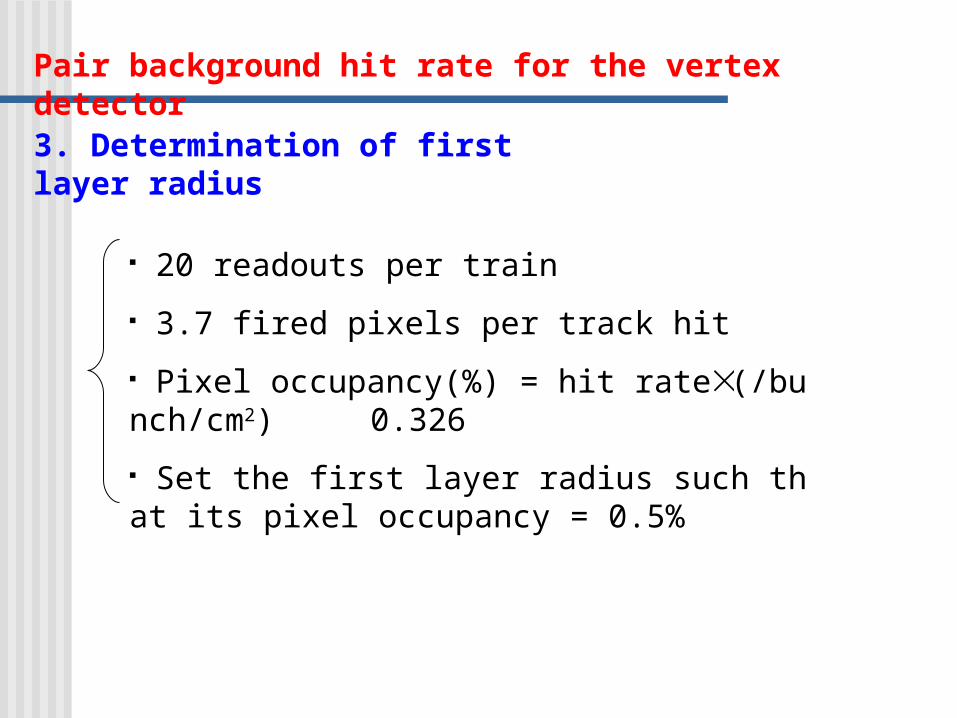
3. Determination of first layer radius
20 readouts per train
3.7 fired pixels per track hit
Pixel occupancy(%) = hit rate (/bunch/cm2) 0.326
Set the first layer radius such that its pixel occupancy = 0.5%
Pair background hit rate for the vertex detector

0.5 % occupancy occurs at
3/))2(1exp(0)( pxpxppxf fit function:
tesla)(5 cm 0.0291.554R1
tesla)(4 cm 028.01.694R1
tesla)(3 cm 0.0341.920R1
3 tesla 4 tesla 5 tesla
First layer hit rate vs. first layer radius

Impact parameter resolutions
1. TRACKERR
TRACKERR:
FORTRAN program to calculate tracking error matrix with using cylindrically symmetric system.
Energy loss, energy loss fluctuation and multiple scattering effects are included. Track fitting uses Kalman filter.
Estimates the impact parameter resolutions and momentum resolutions using TRACKERR. (assume pion).

Detector configurations for TRACKERR
3 tesla 4 tesla 5 teslaBeam pipe (Be)
VTX detector (Si pixel)
IT (Si strip)
TPC
5):2:93
CH:CO:(Ar 42
m250 500, (dBP) thickness, (cm) 0.4RR VTX1bp μ
m50 100, 300, (dVTX) thicknessm,2σ
(4layers), 1.2cm layer each between distance
cm92.1R VTX1 1.69cm 1.55cm
m300 thicknessm,10σ
(5layers), 7cm layer each between distance 3cm,RR
rφ
VTX4IT1
45cm R (2mm,6mm),y)(x,:size Pad m,150σ innerrφ
200cm R outer 160cm 130cm
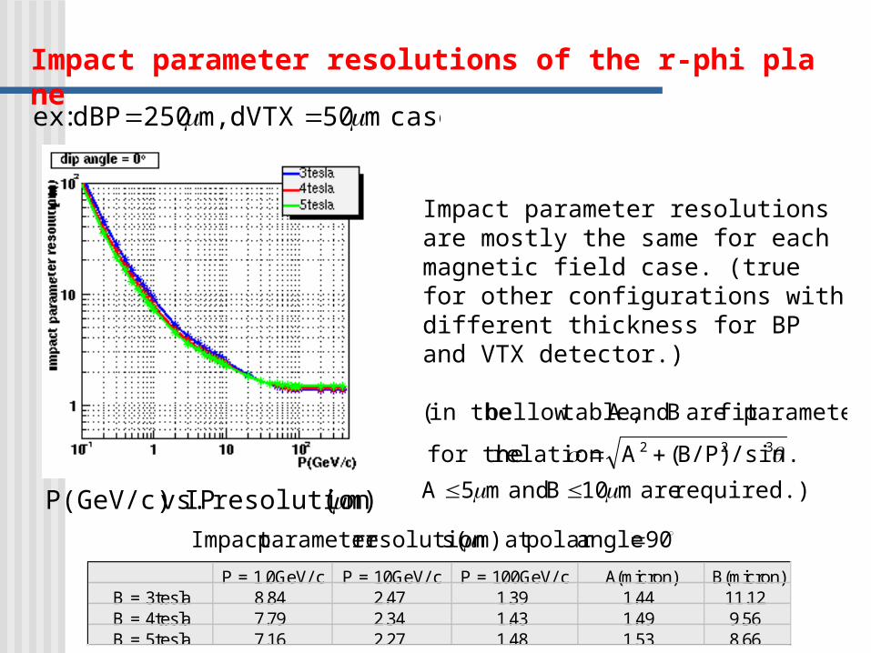
Impact parameter resolutions of the r-phi plane
case m50 dVTX m,250 dBP :ex
required.) are m10B and m5A
./sinB/P)(Arelation for the
parametersfit are B andA table,bellow in the(
322
Impact parameter resolutions are mostly the same for each magnetic field case. (true for other configurations with different thickness for BP and VTX detector.)
m)( resolution IP vs.P(GeV/c) 90 anglepolar at m)( sresolutionparameter Impact
P = 1.0GeV/ c P = 10GeV/ c P = 100GeV/ c A(micron) B(micron)B = 3tesla 8.84 2.47 1.39 1.44 11.12B = 4tesla 7.79 2.34 1.43 1.49 9.56B = 5tesla 7.16 2.27 1.48 1.53 8.66

Other configuration results are as follows (at polar angle = 90 deg.):
small. quite are sdifference But the cases. 5tesla 4, B
nbetter tha is case 3tesla B 30GeV/c,~ PFor
90 anglepolar at m)( sresolutionparameter Impact
For P = 1GeV/c 3tesla is worse than 4(5) tesla by 12.0(19.2) %.
For P = 10GeV/c 3tesla is worse than 4(5) tesla by 6.4(8.8) %.
dBP (micron) dVTX(micron) B (tesla) P = 1.0GeV/ c P = 10GeV/ c P = 100GeV/ c A(micron) B(micron)3 16.22 3.33 1.44 1.33 22.314 14.24 3.08 1.47 1.38 19.385 13.03 2.94 1.52 1.37 18.453 10.57 2.69 1.40 1.42 13.694 9.32 2.52 1.44 1.47 11.835 8.56 2.44 1.49 1.49 10.963 8.84 2.47 1.39 1.44 11.124 7.79 2.34 1.43 1.49 9.565 7.16 2.27 1.48 1.53 8.66
500 300
100
50
250
Impact parameter resolutions of the r-phi plane
Momentum resolutions
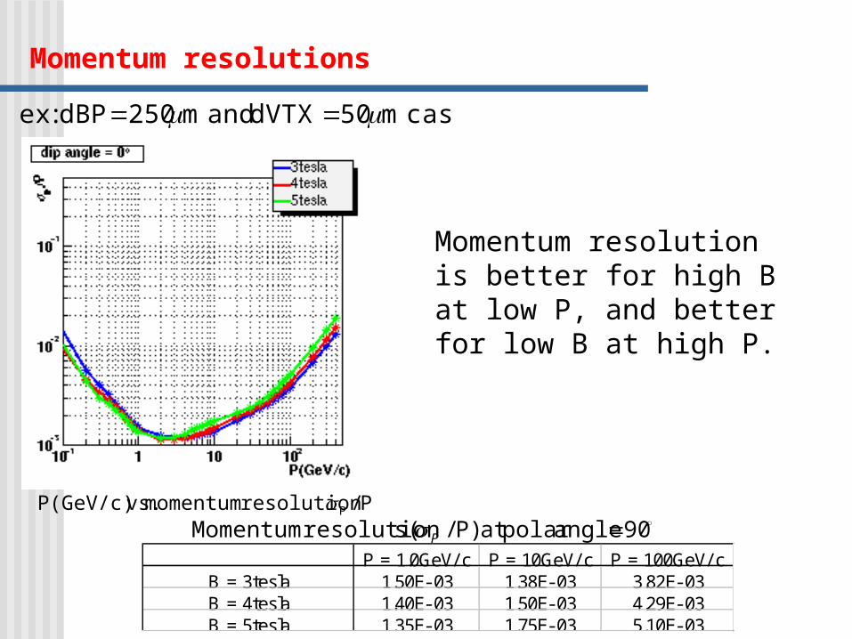
case m50 dVTX and m250 dBP:ex
P/ resolution momentum vs.P(GeV/c) P
Momentum resolution is better for high B at low P, and better for low B at high P.
P = 1.0GeV/ c P = 10GeV/ c P = 100GeV/ cB = 3tesla 1.50E- 03 1.38E- 03 3.82E- 03B = 4tesla 1.40E- 03 1.50E- 03 4.29E- 03B = 5tesla 1.35E- 03 1.75E- 03 5.10E- 03
90 anglepolar at P)/( sresolution Momentum P
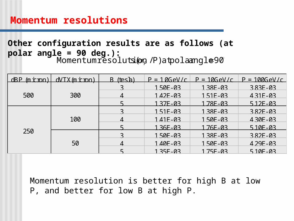
Other configuration results are as follows (at polar angle = 90 deg.):
90 anglepolar at P)/( sresolution Momentum P
Momentum resolution is better for high B at low P, and better for low B at high P.
dBP (micron) dVTX(micron) B (tesla) P = 1.0GeV/ c P = 10GeV/ c P = 100GeV/ c3 1.50E- 03 1.38E- 03 3.83E- 034 1.42E- 03 1.51E- 03 4.31E- 035 1.37E- 03 1.78E- 03 5.12E- 033 1.51E- 03 1.38E- 03 3.82E- 034 1.41E- 03 1.50E- 03 4.30E- 035 1.36E- 03 1.76E- 03 5.10E- 033 1.50E- 03 1.38E- 03 3.82E- 034 1.40E- 03 1.50E- 03 4.29E- 035 1.35E- 03 1.75E- 03 5.10E- 03
300
100
50
500
250
Momentum resolutions
Impact parameter resolutions
2. Satellites (not finished…)
Satellites:
JSF based tracking program for the Jupiter. (under construction…)
tracking is performed by track ID
the material can be included as “uniform” one to calculate the error. (TPC-like)
cylindrical layer
the present condition:

Impact parameter resolutions
Detector configuration for the Jupiter and Satellites
3 teslaBeam pipe (Be)
VTX detector(Si)
IT (Si)
TPC
10):90
CH:(Ar 4
m500 thickness, 1.8(cm) R bp μ
m300 thicknessm,4σ
(4layers), 1.2cm layer each between distance
2.4cm layer innermost theof radius
m562 thicknessm,10σ
(5layers), 7cm layer each between distance
9.0cm, layer innermost theof radius
rφ
layers-130 m,150
157cm,R 40cm, R outin
r
B field
Impact parameter resolutions
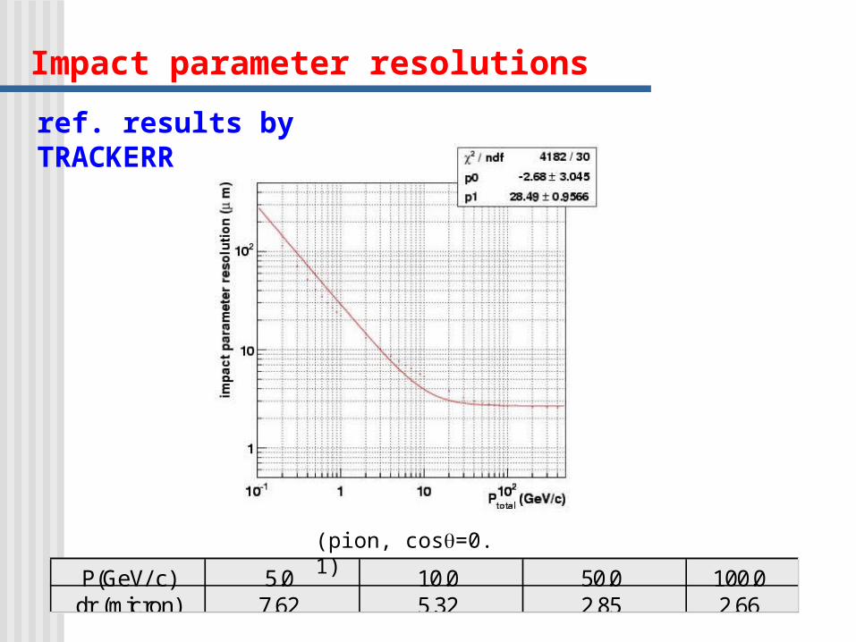
ref. results by TRACKERR
P(GeV/ c) 5.0 10.0 50.0 100.0dr (micron) 7.62 5.32 2.85 2.66
(pion, cos=0.1)
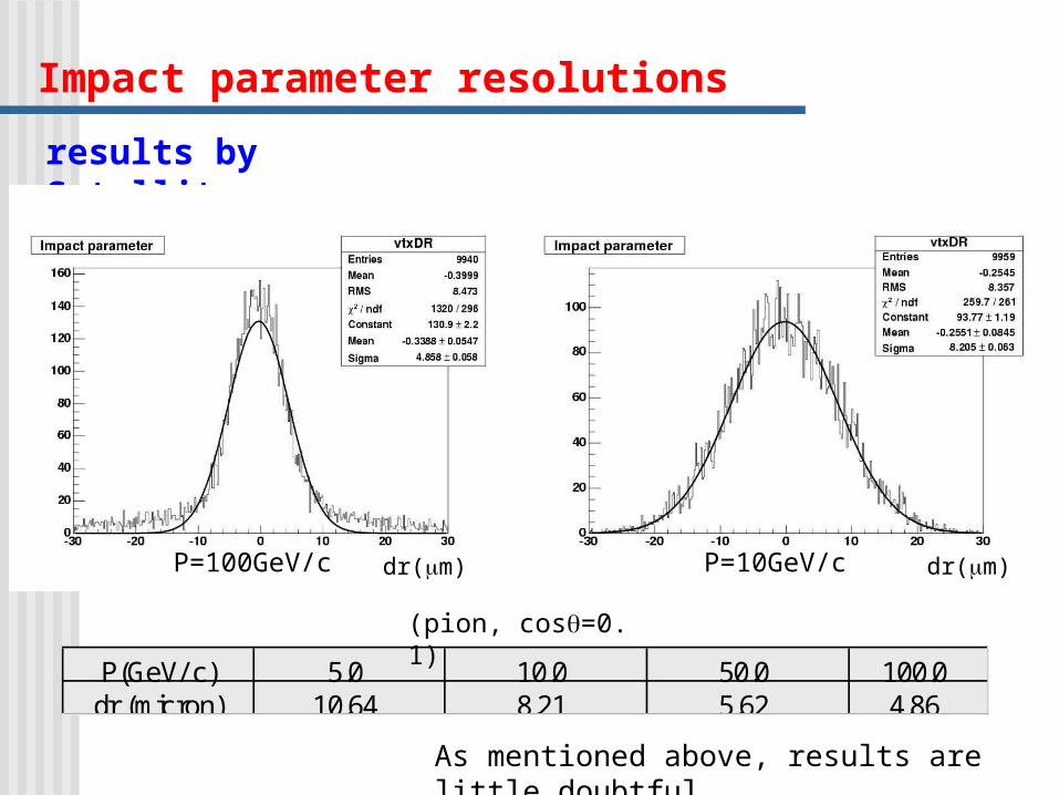
Impact parameter resolutions
results by Satellites
P(GeV/ c) 5.0 10.0 50.0 100.0dr (micron) 10.64 8.21 5.62 4.86
(pion, cos=0.1)
P=10GeV/c dr(m)P=100GeV/c dr(m)
As mentioned above, results are little doubtful…
Next Plan
estimate the impact parameter resolutions using Satellites
estimate the b-tag, c-tag efficiency (with pair background)
To do…
include thin layer construction (already implemented by Yamaguchi-san?)
make a track finder
include the (pair) background hits in Satellites
other detector configurations (FPCCD etc.)


