BAGHJAN – MADHUBAN PIPELINE PROJECT (ASSAM) BID DOCUMENT FOR PROCUREMENT OF BI-DIRECTIONAL SCRAPPER TRAP, PIG SIGNALLERS, PSV & QOEC Tender no. CPG9496P19 VOLUME – II OF II PREPARED AND ISSUED BY MECON LIMITED (A Govt. of India Undertaking) Delhi, India
Transcript
BAGHJAN – MADHUBAN PIPELINE PROJECT (ASSAM)
BID DOCUMENT FOR PROCUREMENT OF
BI-DIRECTIONAL SCRAPPER TRAP,
PIG SIGNALLERS, PSV & QOEC
Tender no. CPG9496P19
VOLUME – II OF II
PREPARED AND ISSUED BY
MECON LIMITED (A Govt. of India Undertaking)
Delhi, India
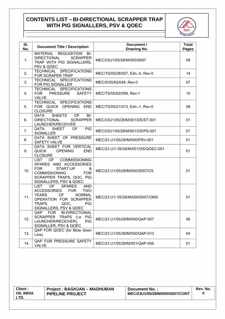
CONTENTS LIST – BI-DIRECTIONAL SCRAPPER TRAP WITH PIG SIGNALLERS, PSV & QOEC
Client : OIL INDIA LTD.
Project : BAGHJAN – MADHUBAN PIPELINE PROJECT
Document No. : MEC/23U1/05/28/M/000/S007/CONT
Rev. No. 0
Sl. No. Document Title / Description Document /
Drawing No. Total Pages
1.
MATERIAL REQUISITION BI-DIRECTIONAL SCRAPPER TRAP WITH PIG SIGNALLERS, PSV & QOEC
MEC/23U1/05/28/M/000/S007 09
2. TECHNICAL SPECIFICATIONS FOR SCRAPER TRAP MEC/TS/05/28/007, Edn.-0, Rev-0 14
3. TECHNICAL SPECIFICATIONS FOR PIG SIGNALLER MEC/S/05/62/048, Rev-0 07
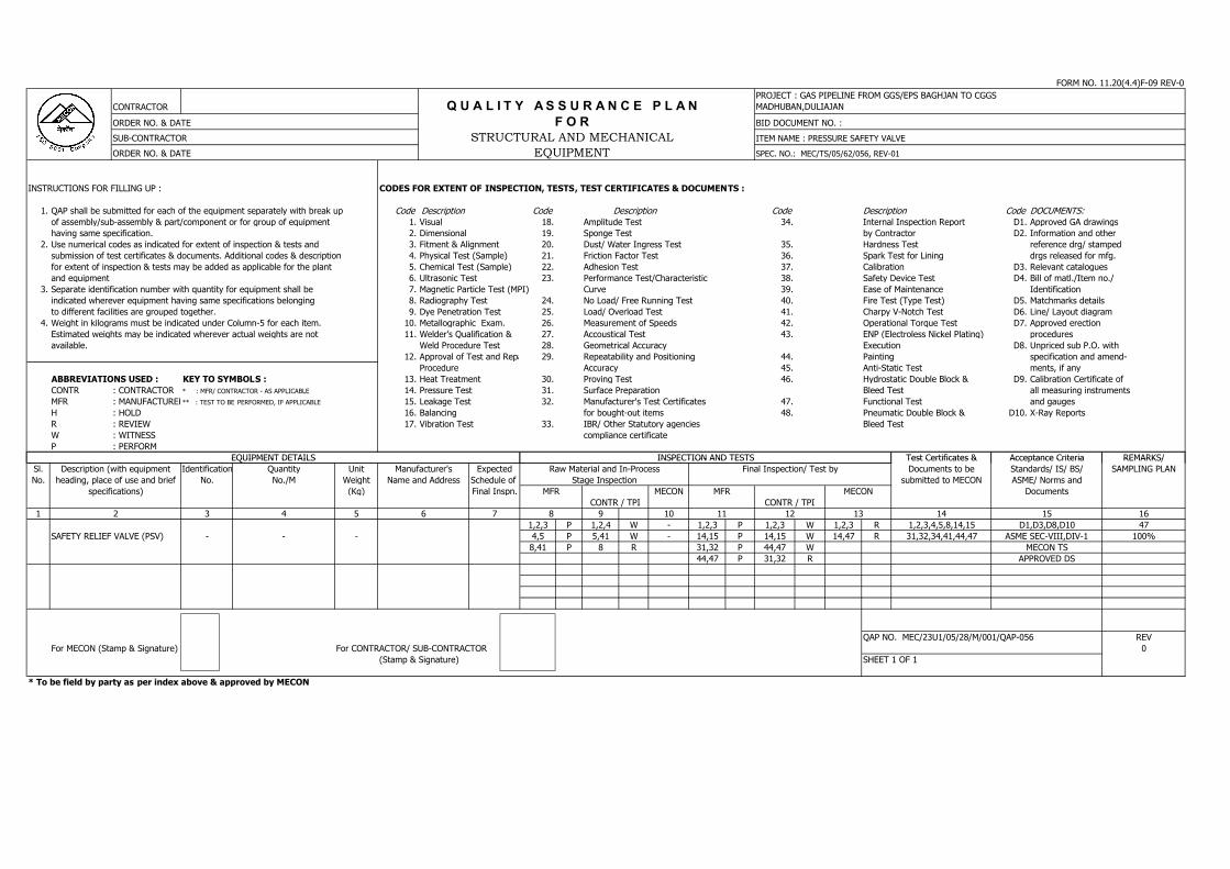
4. TECHNICAL SPECIFICATIONS FOR PRESSURE SAFETY VALVE
MEC/TS/05/62/056, Rev-1 10
5. TECHNICAL SPECIFICATIONS FOR QUICK OPENING END CLOSURE
MEC/TS/05/21/013, Edn.-1, Rev-0 08
6. DATA SHEETS OF BI-DIRECTIONAL SCRAPPER LAUNCHER/RECEIVER
MEC/23U1/05/28/M/001/DS/ST-001 01
7. DATA SHEET OF PIG SIGNALLER MEC/23U1/05/28/M/001/DS/PS-001 01
8. DATA SHEET OF PRESSURE SAFETY VALVE MEC/23 U1/05/28/M/000/PSV-001 01
9. DATA SHEET FOR VERTICAL QUICK OPENING END CLOSURE
MEC/23 U1/ 05/28/M/001/DS/QOEC-001 01
10.
LIST OF COMMISSIONING SPARES AND ACCESSORIES FOR START-UP & COMMISSIONING FOR SCRAPPER TRAPS, QOC, PIG SIGNALLERS, PSV & QOEC
MEC/23 U1/05/28/M/000/S007/CS 01
11.
LIST OF SPARES AND ACCESSORIES FOR TWO YEARS OF NORMAL OPERATION FOR SCRAPPER TRAPS, QOC, PIG SIGNALLERS, PSV & QOEC
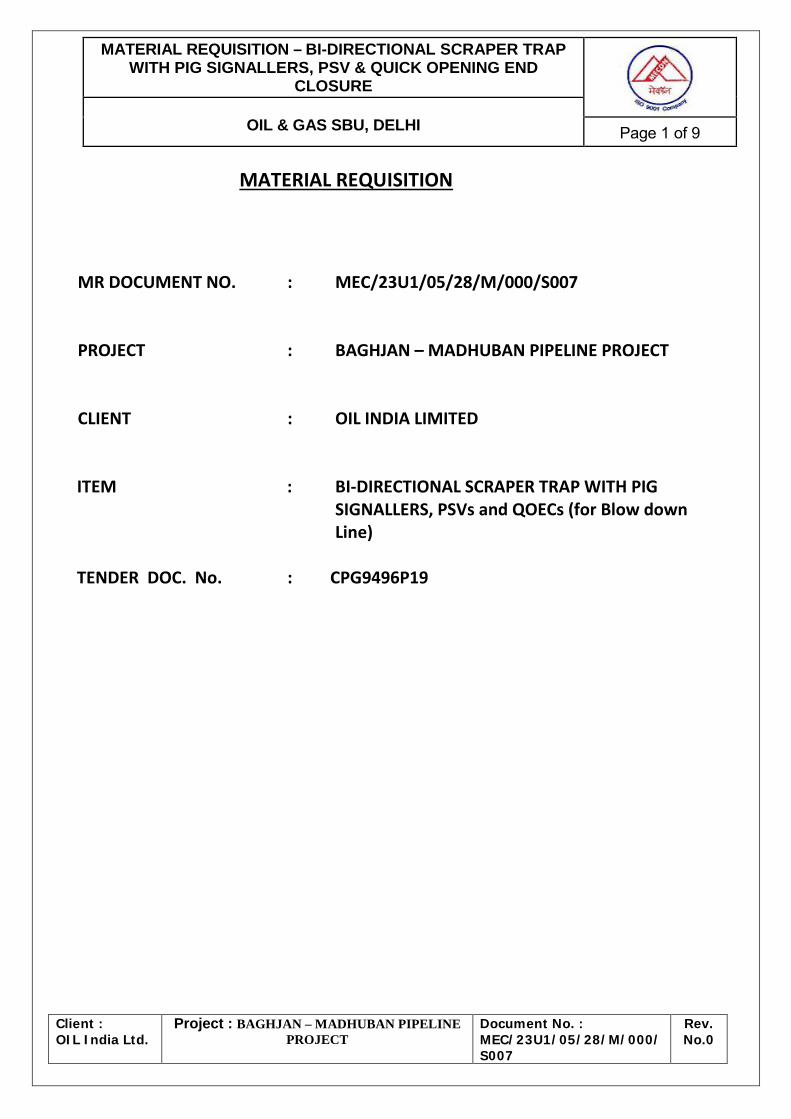
CLIENT : OIL INDIA LIMITED ITEM : BI-DIRECTIONAL SCRAPER TRAP WITH PIG
SIGNALLERS, PSVs and QOECs (for Blow down Line)
TENDER DOC. No. : CPG9496P19
MATERIAL REQUISITION – BI-DIRECTIONAL SCRAPER TRAP WITH PIG SIGNALLERS, PSV & QUICK OPENING END
CLOSURE
OIL & GAS SBU, DELHI Page 2 of 9
Client : OIL India Ltd.
Project : BAGHJAN – MADHUBAN PIPELINE PROJECT
Document No. : MEC/23U1/05/28/M/000/S007
Rev. No.0
1.0 SCOPE OF SUPPLY
The Scope of supply includes Scrapper Traps (i.e Pig Launchers /Receivers) System welded with Quick Opening End Closures (QOEC) including Pig signalers, Pressure Safety Valves (PSV) and Quick Opening End Closures (QOEC) suitable for vertical installation on Blow down pipeline. 2.0 MATERIAL REQUISITION
MR Item No.
Description Tag No. Qty. Remarks Destination / Store
1.0
Design, Manufacture & Fabrication, Procurement of Materials and bought out components, assembly at shop, inspection, testing at manufacturer's works, preparation of shipment / packing, transport / delivery of the Bi-Directional Scrapper Trap System suitable for accommodating intelligent pigs & other cleaning / displacement / gauging pigs, welded with Quick Opening End Closure (QOEC) suitable for horizontal installation including all accessories required to make above Bi-Directional Scrapper Trap system complete operational and QOEC shall be hand operated by a s ingle lever operation and operable by one operator. Scope of supply shall include but not limited to supply & placement of perforated SS Tray inside the Bi-Directional Scrapper Trap, supply and mounting of Pig Signaller on the Bi-Directional Scrapper Trap, supply of Pig Signaller with welded isolation ball valve for mounting on pipeline, supply of Pig Handling (insertion / retraction) System, supply of Jib Crane of sufficient capacity including supply of matching flanges for all the flanged end nozzle. Required studs, Nuts, bolts, Gaskets and foundation Bolts for Bi-Directional Scrapper Trap & associated accessories as described below are included in scope of supply. Scope of supply shall include supply of all commissioning spares & documentation as per the Material Requisition, Notes to Material Requisition, Data sheet, MECON’s Standard specifications etc. and other codes and standards attached or referred.
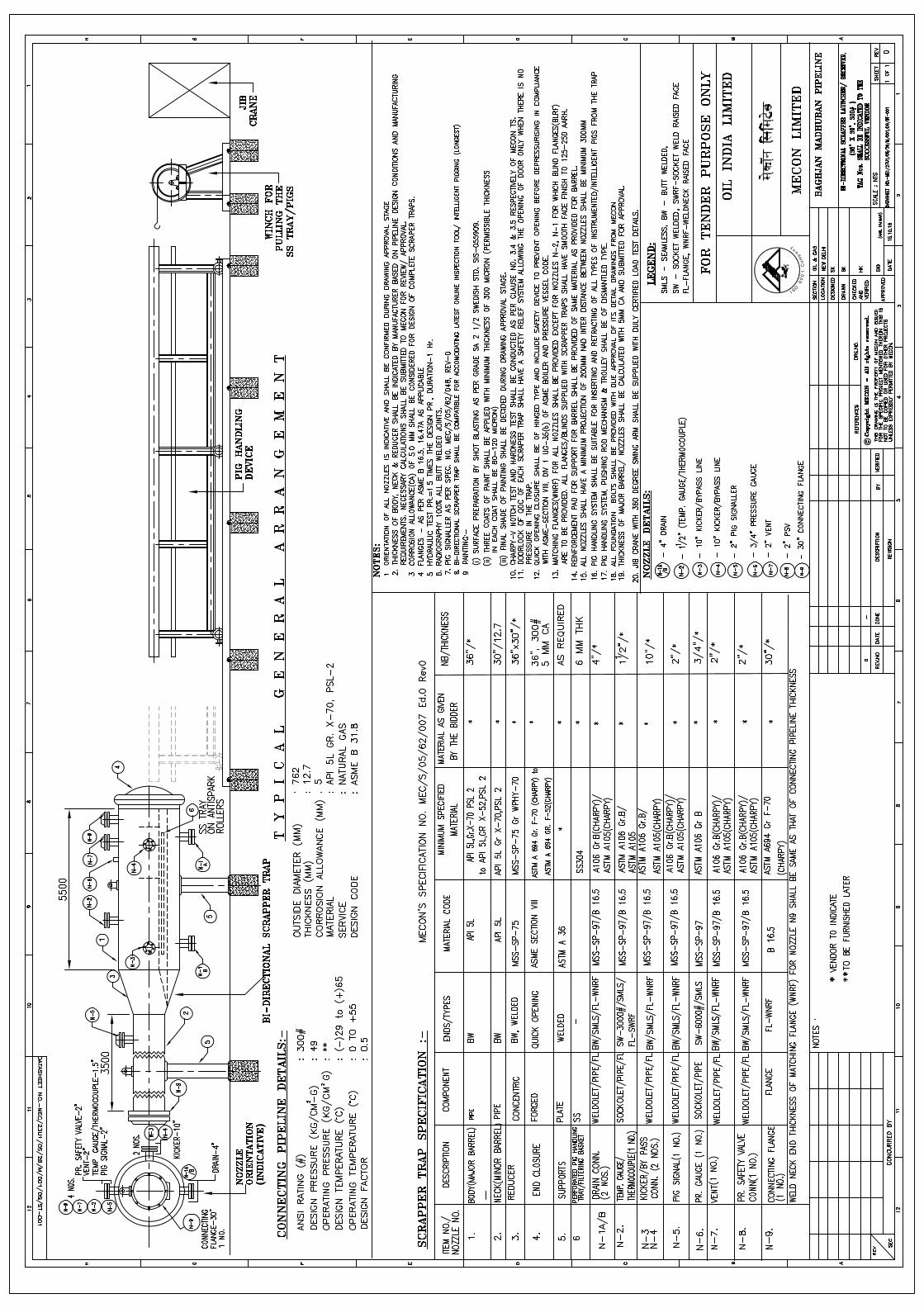
1.1 For supply of Bi-Directional Scrapper Trap (i.e., Pig Launcher/Receiver of Size 36”x30”NB & ANSI Class 300#) System along with accessories
1.1.1 Supply of Bi-Directional Scrapper Trap (i.e., Pig Launcher/Receiver of Size 36”x30”NB & ANSI Class 300#) along with Quick Opening End closure as per Specification No. MEC/TS/05/28/007, Edn.-0, Rev-0 & as per Data Sheet No. MEC/23U1/05/28/M/001/DS/ST-001
* 02 Nos.
Duliajan, Assam
1.1.2 Supply of Pig Signaler without isolation valve mounted on Bi-Directional Scrapper Trap mentioned in 1.1.1 above as per Specification No. MEC/S/05/62/048, Rev-0 and Data Sheet No. MEC/23U1/05/28/M/001/DS/PS-001
* 02 Nos.
1.1.3 Supply of Door Seal for Quick Opening End Closure (QOEC) welded on Bi-Directional Scrapper Traps as mentioned in item no. 1.1.1 above
- 04 Nos.
Commissioning Spares (@ 2 Nos./ Scrapper Trap)
1.1.4 Supply of complete set of spare seals for Pig Signalers as mentioned in item no. 1.1.2 above
- 04 Sets
Commissioning Spares (@ 2
Sets/ Pig Signaller)
1.1.5 Supply of Pig Signaler welded with isolation valve for mounting on 30" NB Pipeline as per Specification No. MEC/S/05/62/048, Rev-0 and Data Sheet No. MEC/23U1/05/28/M/001/DS/PS-001
* 02 Nos.
MATERIAL REQUISITION – BI-DIRECTIONAL SCRAPER TRAP WITH PIG SIGNALLERS, PSV & QUICK OPENING END
CLOSURE
OIL & GAS SBU, DELHI Page 3 of 9
Client : OIL India Ltd.
Project : BAGHJAN – MADHUBAN PIPELINE PROJECT
Document No. : MEC/23U1/05/28/M/000/S007
Rev. No.0
MR Item No.
Description Tag No. Qty. Remarks Destination / Store
1.1.6 Supply of complete set of spare seals for Pig Signalers as mentioned in item no. 1.1.5 above
- 04 Sets
Commissioning Spares (@ 2
Sets/ Pig Signaller)
1.1.7 Supply of jib crane of capacity 3.0 ton to suit the pig handling for scrapper trap specified in 1.1.1 above.
- 02
1.1.8 Supply of Pig Handling System with insertion / retraction facilities for inserting/pulling the SS Tray / Pigs to suit scrapper trap specified in 1.1.1 above.
- 02
1.1.9 PSV suitable for mounting on scrapper trap specified in 1.2.1 as per Specification No. MEC/S/05/62/056, Rev-1 and Data Sheet No. MEC/23U1/05/28/M/001/DS/PSV-001
* 02
2.0 Design, Engineering, Manufacture & Fabrication, Procurement of Materials and bought out components, assembly at shop, inspection, testing at manufacturer's works, preparation of shipment / packing, transport / delivery of the Quick Opening End Closure suitable for vertical installation at height of 3.0 metre from working platform / ground level on Blow down lines and capable of operation from working platform / ground level. Scope of supply shall include supply of all commissioning spares & documentation as per the Material Requisition, Notes to Material Requisition, Data sheet, MECON’s Standard specifications etc. and other codes and standards attached or referred.
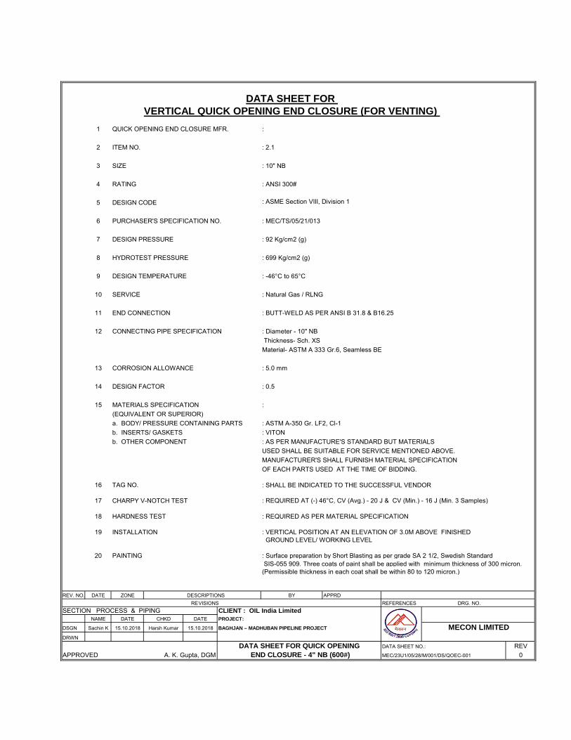
2.1 For Supply of QOEC system suitable for vertical installation of size 10”NB, 300#
2.1.1 Supply of Quick Opening End Closure of size 10” NB, 300# as per Specification No. MEC/TS/05/21/013, Edition-1 and Data Sheet No. MEC/23U1/05/28/M/001/DS/QOEC-001
* 03 Duliajan, Assam
2.1.2 Supply of ‘O’ ring for Quick Opening End Closure (QOEC) mentioned in item no. 2.1.1 above
- 06 Commissioning Spares (@ 2 Nos./ QOEC)
Notes:
1. Compliance with Specification: The Vendor shall be completely responsible for the
design, materials, manufacture & fabrication, testing, inspection, preparation for shipment and transport of the above equipment strictly in accordance with the MR and all attachment thereto. All pressure containing parts of all the items shall be provided with EN 10204-3.2 certificates.
2. Vendor’s Scope: Vendor scope of work includes the equipment with all internals
and accessories shown on the datasheets, specifications and all unmentioned parts necessary for a satisfactory operation and testing except those which are indicated to be out of the vendor’s supply.
MATERIAL REQUISITION – BI-DIRECTIONAL SCRAPER TRAP WITH PIG SIGNALLERS, PSV & QUICK OPENING END
CLOSURE
OIL & GAS SBU, DELHI Page 4 of 9
Client : OIL India Ltd.
Project : BAGHJAN – MADHUBAN PIPELINE PROJECT
Document No. : MEC/23U1/05/28/M/000/S007
Rev. No.0
3. Inspection:
The Successful Vendor shall propose minimum four (4) nos. of TPIA’s from the below listed TPIA’s along with QAP submission. OIL/MECON shall approve any one TPIA out of the four (4) nos. proposed TPIA’s. The Successful Vendor shall appoint the approved TPIA for inspection purpose and mention name of the approved TPIA in QAP. i. Det Norske Veritas (DNV) ii. BVQI iii. Technische Ulierwachungs Verein (TUV) iv. LIoyds v. RITES vi. I.R.S. vii. Tuboscope Vetco
Apart from inspection by TPIA, inspection shall also be performed by MECON /
OIL’s delegate, as set out and specified in the codes and particular documents forming this MR.
Vendor must note that stage wise inspection for complete fabrication, testing
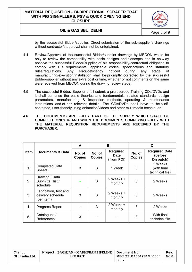
including the raw material inspection to be carried out. 4. DOCUMENTS & DATA REQUIREMENTS 4.1 The table hereunder specifies the quantities and the nature of the documents to be
submitted by the Vendor to Purchaser. 4.1.1 The documents required at the inquiry stage and to be included in the bid are listed
under column A of table below under note no. 4.6. 4.1.2 The documents required after award of the Contract and subject to the written
approval of the Purchaser are listed under column B of table below under note no. 4.6.
4.1.3 The final and c ertified documents are listed under column C of table below under
note no. 4.6. 4.2 Any document, even when preliminary, shall be binding and therefore duly identified
and signed by the Vendor. It shall bear the Purchaser’s Project reference, the Material Requisition number and the identification number.
4.3 The drawings/documents shall be reviewed, checked, approved and duly
signed/stamped by successful Bidder/supplier before submission. Revision number shall be c hanged during submission of the revised successful Bidder/supplier documents and all revisions shall be highlighted by clouds. Whenever the successful Bidder/supplier require any sub-supplier drawings to be reviewed by MECON, the same shall be submitted by the supplier after duly reviewed, approved and stamped
MATERIAL REQUISITION – BI-DIRECTIONAL SCRAPER TRAP WITH PIG SIGNALLERS, PSV & QUICK OPENING END
CLOSURE
OIL & GAS SBU, DELHI Page 5 of 9
Client : OIL India Ltd.
Project : BAGHJAN – MADHUBAN PIPELINE PROJECT
Document No. : MEC/23U1/05/28/M/000/S007
Rev. No.0
by the successful Bidder/supplier. Direct submission of the sub-supplier’s drawings without contractor’s approval shall not be entertained.
4.4 Review/Approval of the successful Bidder/supplier drawings by MECON would be
only to review the compatibility with basic designs and c oncepts and in no w ay absolve the successful Bidder/supplier of his responsibility/contractual obligation to comply with PR requirements, applicable codes, specifications and statutory rules/regulations. Any error/deficiency noticed during any stage of manufacturing/execution/installation shall be pr omptly corrected by the successful Bidder/supplier without any extra cost or time, whether or not comments on the same were received from MECON during the drawing review stage.
4.5 The successful Bidder/ Supplier shall submit a prerecorded Training CDs/DVDs and
it shall comprise the basic theories and fundamentals, related standards, design parameters, manufacturing & inspection methods, operating & maintenance instructions and ot her relevant details. The CDs/DVDs shall have to be s elf-contained, user-friendly using animation/videos and other multimedia techniques.
4.6 THE DOCUMENTS ARE FULLY PART OF THE SUPPLY WHICH SHALL BE
COMPLETE ONLY IF AND WHEN THE DOCUMENTS COMPLYING FULLY WITH THE MATERIAL REQUISITION REQUIREMENTS ARE RECEIVED BY THE PURCHASER.
Item Documents & Data
A B C
No. of Copies
No. of Copies
Required Date
(from FOI) No. of Copies
Required Date (before
Dispatch)
1. Completed Data Sheets 3 3 1 Week 3
2 Weeks (with final
technical file)
2. Drawing / Data Submittal list / schedule
- 3 2 Weeks + monthly 3 2 Weeks
3. Fabrication, test and delivery schedule (per item)
MATERIAL REQUISITION – BI-DIRECTIONAL SCRAPER TRAP WITH PIG SIGNALLERS, PSV & QUICK OPENING END
CLOSURE
OIL & GAS SBU, DELHI Page 6 of 9
Client : OIL India Ltd.
Project : BAGHJAN – MADHUBAN PIPELINE PROJECT
Document No. : MEC/23U1/05/28/M/000/S007
Rev. No.0
Item Documents & Data
A B C
No. of Copies
No. of Copies
Required Date
(from FOI) No. of Copies
Required Date (before
Dispatch)
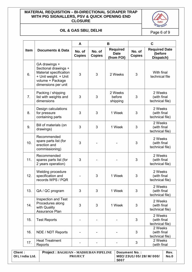
6.
GA drawings + Sectional drawings + Material specification + Unit weight. + Unit volume + Package dimensions per unit
3 3 2 Weeks 3 With final technical file
7. Packing / shipping list with weights and dimensions
3 3 2 Weeks before
shipping 3
2 Weeks (with final
technical file)
8. Design calculations for pressure containing parts
3 3 1 Week 3 2 Weeks (with final
technical file)
9. Bill of materials (on drawings) 3 3 1 Week 3
2 Weeks (with final
technical file)
10.
Recommended spare parts list (for erection and commissioning)
3 - - 3 2 Weeks (with final
technical file)
11. Recommended spares parts list (for 2 years operation)
3 - - 3 2 Weeks (with final
technical file)
12. Welding procedure specification and records WPS / PQR
- 3 1 Week 3 2 Weeks (with final
technical file)
13. QA / QC program 3 3 1 Week 3 2 Weeks (with final
technical file)
14.
Inspection and Test Procedures along with Quality Assurance Plan
3 3 1 Week 3 2 Weeks (with final
technical file)
15. Test Reports - - - 3 2 Weeks (with final
technical file)
16. NDE / NDT Reports - - - 3 2 Weeks (with final
technical file)
17. Heat Treatment Reports - - - 3 2 Weeks
(with final
MATERIAL REQUISITION – BI-DIRECTIONAL SCRAPER TRAP WITH PIG SIGNALLERS, PSV & QUICK OPENING END
CLOSURE
OIL & GAS SBU, DELHI Page 7 of 9
Client : OIL India Ltd.
Project : BAGHJAN – MADHUBAN PIPELINE PROJECT
Document No. : MEC/23U1/05/28/M/000/S007
Rev. No.0
Item Documents & Data
A B C
No. of Copies
No. of Copies
Required Date
(from FOI) No. of Copies
Required Date (before
Dispatch) technical file)
18. Hydrotest and air test report - - - 3
2 Weeks (with final
technical file)
19. Maintenance and operating manuals - - - 3
2 Weeks (with final
technical file)
20.
Installation instructions & Site inspection procedure
- - - 3 2 Weeks (with final
technical file)
21. Material certificate as per EN 10204 - 3.2 - - - 3
2 Weeks (with final
technical file)
22. Painting system description & procedure
3 3 1 week 3 2 Weeks (with final
technical file)
23. List of sub-vendors with their scope 3 3 1 week - -
24.
Training CDs/DVDs covering design, operation & maintenance
- - - 3 2 Weeks (with final
technical file)
25.
Final technical file, preliminary copy for approval (in soft & hardcopy)
- 3
2 weeks before
Dispatch/ shipping
- -
26. Final technical file (in soft & hardcopy) - - - 3 Before shipping
MATERIAL REQUISITION – BI-DIRECTIONAL SCRAPER TRAP WITH PIG SIGNALLERS, PSV & QUICK OPENING END
CLOSURE
OIL & GAS SBU, DELHI Page 8 of 9
Client : OIL India Ltd.
Project : BAGHJAN – MADHUBAN PIPELINE PROJECT
Document No. : MEC/23U1/05/28/M/000/S007
Rev. No.0
Item Documents & Data
A B C
No. of Copies
No. of Copies
Required Date
(from FOI) No. of Copies
Required Date (before
Dispatch) NOTES
I. In case of e-bids, only single copy of documents / drawings / data under column A need be uploaded.
II. Durations in column B (required date) are weeks after FOI/FOA or as indicated in
Table.
a. Durations in column C (required date) are weeks after document approval or as indicated in Table.
b. Due date of each document may be proposed.
III. Final technical file shall be supplied in hard copy as indicated and in electronic format (.pdf Acrobat files) on six (6) CD-ROMs.
The above documents & data requirements shall also be supplemented by all requirements of clause 10.0 of MECON’s T.S. No. MEC/S/05/62/007, R-1. ; clause no. 9.0 of MECON’s T.S. No. MEC/S/05/62/048, Rev.-0. ; of clause 1.3 of MECON’s T.S. No. MEC/TS/05/62/056, Rev-1. ; clause no. 10.0 of MECON’s T.S. No. MEC/TS/05/21/013, Edn.-1, Rev-1
5. Vendor to indicate in his offer the gross weight (in kg or Metric Tonne) per unit,
volume (in m3) per unit and dimensions (L x B x H) of package (wooden box, etc.) to accommodate unit quantity.
6. Vendor shall establish the equivalence/superiority of any material proposed (With
justification of material properties and av ailability) other than that specified in Datasheet. Vendor shall also indicate the ASTM equivalent of his proposed material as well as of all the AISI designated materials specified in datasheets.
7. Vendors to note that for minimum inspection and testing requirement of the supplied
item shall be governed by attached QAP with this MR. However, Vendor shall submit their QAP for Approval covering the requirement specified in attached QAP.
8. Bidders to note that all the documents/drawings submitted by them as a part of bid
shall be considered only to assess Bidder’s technical capability and shall in no way absolve them from complying with all the requirements of the Tender. All items to be supplied by the Bidder shall be strictly in accordance with tender requirements.
MATERIAL REQUISITION – BI-DIRECTIONAL SCRAPER TRAP WITH PIG SIGNALLERS, PSV & QUICK OPENING END
CLOSURE
OIL & GAS SBU, DELHI Page 9 of 9
Client : OIL India Ltd.
Project : BAGHJAN – MADHUBAN PIPELINE PROJECT
Document No. : MEC/23U1/05/28/M/000/S007
Rev. No.0
9. In the event of Conflict/inconsistency among the documents attached/ referred, the following order of precedence generally shall govern in interpretation of various requirements / data. • Material / Purchase Requisition • Datasheets • Technical Specification • Codes and Standards • Vendor’s Standards However, Owner/Consultant reserves the right to consider most stringent requirement among the document attached / referred.
11.0 Following are the preferred manufacturers of Pig Signallers & PSV a) For Pig-Signaller:- M/s G.D. Engg., M/s Pipeline Engg., M/s Piping Technologies &
M/s Inpipe Products. b) For PSV (Pressure safety Valve)- M/s Keystone Valves (India) Pvt. Ltd. Baroda, M/s
Sebim Sarasin Valves India (P) Ltd., M/s Tyco Sanmar Ltd, M/s Parcol Spa, Italy, M/s Tai Milano SPA, Italy, M/s Emerson Process, Singapore,, M/s Instrumentation Limited, Palghat
In case bidder propose pig signaller and PSV manufacturers other than above list of
preferred manufacturers, bidder shall submit in support of PTR, all details/ documents for both type (with/ without isolation valve) pig signaler and f or PSV complying to the requirement of specification and datasheet enclosed. Submitted PTR should contain successful supply record of minimum one number of respective item of same size & rating (or higher) as quoted for.
12.0 Spares List (Start-Up & Commissioning– Bi-Directional Scrapper Trap With Pig
Signallers, PSV & QOEC And Spares List (2 Years Normal Operation)– Bi-Directional Scrapper Trap With Pig Signallers, PSV & QOEC are Attached Herewith.
C:\Documents and Settings\hcl\Desktop\Specs\WORKS\48 PIG SIGNALLER\048 - Pig Signaller - TS.doc
SPECIFICATION FOR
PIG SIGNALLERS
SPECIFICATION NO. : MEC/S/05/62/048, Rev-0
MECON LIMITED DELHI - 110 092
MECON LIMITED REGD. OFF RANCHI
PROCESS & PIPING DESIGN SECTION
NEW DELHI
STANDARD SPECIFICATION PIG SIGNALLERS
TECHNICAL SPECIFICATION NO. : MEC/S/05/62/048 REV-0 Page 1 of 6
C:\Documents and Settings\hcl\Desktop\Specs\WORKS\48 PIG SIGNALLER\048 - Pig Signaller - TS.doc
C O N T E N T S Sl.No. Description 1.0 SCOPE 2.0 MATERIALS 3.0 DESIGN AND CONSTRUCTION REQUIREMENTS 4.0 INSPECTION AND TESTS 5.0 TEST CERTIFICATES 6.0 PAINTING, MARKING AND SHIPMENT 7.0 SPARES AND ACCESSORIES 8.0 GUARANTEE 9.0 DOCUMENTATION PREPARED BY
CHECKED BY
APPROVED BY
MECON LIMITED REGD. OFF RANCHI
PROCESS & PIPING DESIGN SECTION
NEW DELHI
STANDARD SPECIFICATION PIG SIGNALLERS
TECHNICAL SPECIFICATION NO. : MEC/S/05/62/048 REV-0 Page 2 of 6
C:\Documents and Settings\hcl\Desktop\Specs\WORKS\48 PIG SIGNALLER\048 - Pig Signaller - TS.doc
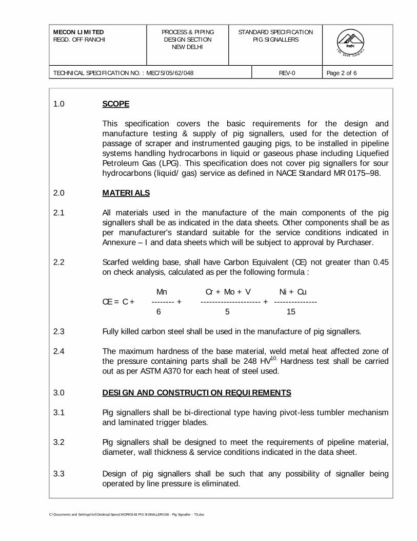
1.0 SCOPE This specification covers the basic requirements for the design and
manufacture testing & supply of pig signallers, used for the detection of passage of scraper and instrumented gauging pigs, to be installed in pipeline systems handling hydrocarbons in liquid or gaseous phase including Liquefied Petroleum Gas (LPG). This specification does not cover pig signallers for sour hydrocarbons (liquid/ gas) service as defined in NACE Standard MR 0175–98.
2.0 MATERIALS 2.1 All materials used in the manufacture of the main components of the pig
signallers shall be as indicated in the data sheets. Other components shall be as per manufacturer's standard suitable for the service conditions indicated in Annexure – I and data sheets which will be subject to approval by Purchaser.
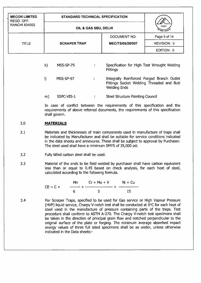
2.2 Scarfed welding base, shall have Carbon Equivalent (CE) not greater than 0.45
on check analysis, calculated as per the following formula : Mn Cr + Mo + V Ni + Cu CE = C + -------- + --------------------- + --------------- 6 5 15 2.3 Fully killed carbon steel shall be used in the manufacture of pig signallers. 2.4 The maximum hardness of the base material, weld metal heat affected zone of
the pressure containing parts shall be 248 HV10. Hardness test shall be carried out as per ASTM A370 for each heat of steel used.
3.0 DESIGN AND CONSTRUCTION REQUIREMENTS 3.1 Pig signallers shall be bi-directional type having pivot-less tumbler mechanism
and laminated trigger blades. 3.2 Pig signallers shall be designed to meet the requirements of pipeline material,
diameter, wall thickness & service conditions indicated in the data sheet. 3.3 Design of pig signallers shall be such that any possibility of signaller being
operated by line pressure is eliminated.
MECON LIMITED REGD. OFF RANCHI
PROCESS & PIPING DESIGN SECTION
NEW DELHI
STANDARD SPECIFICATION PIG SIGNALLERS
TECHNICAL SPECIFICATION NO. : MEC/S/05/62/048 REV-0 Page 3 of 6
C:\Documents and Settings\hcl\Desktop\Specs\WORKS\48 PIG SIGNALLER\048 - Pig Signaller - TS.doc
3.4 Design of pig signallers shall also be such that repair and installation of internals/
accessories are possible under pressure, without removing the unit from the line. 3.5 Pig signallers shall be provided with a visual indicator to indicate the passage
of pigs, by means of spring loaded metal shaft. The arm shall lock in down position when manually reset.
3.7 Pig signallers shall be fitted with sealed, weather proof and explosion proof
microswitch for remote signal indication. The area classification and rating of microswitch shall be as indicated in data sheet. Suitable for installation in NEC class I Division 1, hazardous area. Microswitch shall have the following rating:
2 Amp, 24 Volts, 50 Hz. Type : SPDT. Contacts : 2 NO and 2 NC 3.8 All welds shall be made by welders and welding procedures qualified in
accordance with the provision of ASME Section IX. The procedure qualification shall include hardness test and shall meet the
requirements of clause 2.4 of this specification 3.9 Whenever specified in the data sheet, pig signallers shall be provided with
extension, suitable for installation on underground pipeline. 4.0 INSPECTION AND TESTS 4.1 Manufacturer shall perform all inspection and tests required to supply the
signallers as per the requirements of this specification. 4.2 All pig signallers shall be visually inspected. 4.3 Chemical composition & mechanical properties including hardness shall be
checked for each heat of steel used. 4.4 All welds shall be non destructively examined. 4.5 The welding end shall be inspected ultrasonically over the entire circumference
for lamination type defects. Any lamination larger than 6.35 mm shall not be acceptable.
MECON LIMITED REGD. OFF RANCHI
PROCESS & PIPING DESIGN SECTION
NEW DELHI
STANDARD SPECIFICATION PIG SIGNALLERS
TECHNICAL SPECIFICATION NO. : MEC/S/05/62/048 REV-0 Page 4 of 6
C:\Documents and Settings\hcl\Desktop\Specs\WORKS\48 PIG SIGNALLER\048 - Pig Signaller - TS.doc
4.6 Hydrostatic test shall be conducted at a pressure equal to 1.5 times the design
pressure. Hydrotest duration shall be 15 Minutes. 4.6 Manufacturers shall perform functional tests to establish satisfactory
performance of both manual and electrical indications 5.0 TEST CERTIFICATES 5.1 Manufacturer shall supply the test certificates for material compliance as per the
relevant Material Standards. 5.2 Certificate for hydrostatic test and functional test 5.3 Test reports on heat treatment carried out, if any. 6.0 PAINTING, MARKING AND SHIPMENT 6.1 Exterior surface of the pig signallers shall be thoroughly cleaned, freed from rust
and grease and applied with sufficient coats of corrosion resistant paint. Manufacturer shall indicate the type and corrosion resistant paint used in the drawings submitted for approval. In case of pig signallers with extension, the burried portion shall be coated with three coats of coal tar epoxy resin. The minimum dry film thickness shall be 300 microns.
6.2 A corrosion resistant metal tag shall be permanently attached with each unit,
with the following marking:-
i) Manufacturer’s name i) Suitable for installation in_______mm dia. pipeline ii) ANSI Rating iii) Tag No.
MECON LIMITED REGD. OFF RANCHI
PROCESS & PIPING DESIGN SECTION
NEW DELHI
STANDARD SPECIFICATION PIG SIGNALLERS
TECHNICAL SPECIFICATION NO. : MEC/S/05/62/048 REV-0 Page 5 of 6
C:\Documents and Settings\hcl\Desktop\Specs\WORKS\48 PIG SIGNALLER\048 - Pig Signaller - TS.doc
6.3 Each unit shall be suitably protected to avoid any damage during transit. Care
shall be exercised during packing to prevent any damage to the welding ends. All machined surfaces subject to corrosion shall be well protected by a coat of grease or other suitable materials.
7.0 SPARES AND ACCESSORIES 7.1 Manufacturer shall furnish list of recommended spares and accessories for Pig
Signallers required during start up and commissioning. Cost of such spares shall be included by the Manufacturer in the item rates indicated in Purchase Requisition.
7.2 Manufacturer shall furnish separately a list of recommended spares and
accessories required for two years of normal operation and maintenance of Pig Signallers.
8.0 GUARANTEE 8.1 Manufacturer shall guarantee that the pig signallers comply with the
requirements stated in this specification and in the purchase order. Manufacturer shall replace or repair all parts found to be defective due to inadequate engineering or quality of material. Manufacturer shall replace the signaller without delay, if the defect or malfunctioning cannot be eliminated.
8.2 Any defects occuring within the time period specified elsewhere shall be repaired
making all necessary modifications and repair of defective parts free of charge to the purchaser.
9.0 DOCUMENTATION 9.1 At the time of bidding, bidder shall submit the following documents :- a) General Arrangement drawing with overall dimensions.
b) Clause wise list of deviation from this specification, if any. c) Reference list of similar supplies of pig signaller shall be furnished
including project, year of supply, client, size, rating and service for last five years.
d) Quality Assurance Plan (QAP) enclosed with this tender duly signed, stamped and accepted.
MECON LIMITED REGD. OFF RANCHI
PROCESS & PIPING DESIGN SECTION
NEW DELHI
STANDARD SPECIFICATION PIG SIGNALLERS
TECHNICAL SPECIFICATION NO. : MEC/S/05/62/048 REV-0 Page 6 of 6
C:\Documents and Settings\hcl\Desktop\Specs\WORKS\48 PIG SIGNALLER\048 - Pig Signaller - TS.doc
9.2 Within two weeks of placement of order, the manufacturer shall submit four
copies, but not limited to, of the following drawings, documents and specifications for approval.
a) Fabrication drawings/ sectional arrangement drawings showing all parts
with reference numbers and material specification. b) Assembly drawing with overall dimension. c) Welding and testing procedure.
e) Cable connection details and cable specification.
Once the approval has been given by Purchaser, any change in design, material, etc. shall be notified to the Purchaser whose approval in writing for all changes shall be obtained before Pig Signallers are manufactured.
9.3 Within four weeks from the approval date, Manufacturer shall submit one
reproducible and six copies of the approved drawings and specifications as listed in 9.2 of this specification.
9.4 Prior to shipment, Manufacturer shall submit one reproducible and six copies of
following : a) Test certificates as per clause 5.0 of this specification. b) Manual for installation, erection instructions, maintenance and operation
instructions. 9.5 All documents shall be in English Language.
D:\TS\PSV - TS - 056 (R-1).doc
PROCESS & PIPING DESIGN SECTIONMECON LIMITEDDELHI – 110 092
TECHNICAL SPECIFICATIONFOR
PRESSURE SAFETY VALVES
SPECIFICATION NO. : MEC/TS/05/62/056, Rev-1
MECON LIMITEDDelhi
PROCESS & PIPINGDESIGN SECTION
TECHNICAL SPECIFICATIONFOR
PRESSURE SAFETY VALVES
TECHNICAL SPECIFICATION NO. : MEC/TS/05/62/056 REV-1 Page 1 of 9
D:\TS\PSV - TS - 056 (R-1).doc
C O N T E N T S
Sl.No. Description Page No.
1.0 GENERAL 2
2.0 VALVE SIZING 5
3.0 VALVE CONSTRUCTION 5
4.0 NAMEPLATE 7
5.0 INSPECTION & TESTING 7
6.0 SHIPPING 9
7.0 GUARANTEE 9
8.0 REJECTION 9
Revision No. Date Revised by Checked by Approved by
1 K.P. Singh A.K. Johri Niraj GuptaPREPARED BY :
K.P. SINGH
CHECKED BY :
A.K. JOHRI
APPROVED BY :
NIRAJ GUPTA
MECON LIMITEDDelhi
PROCESS & PIPINGDESIGN SECTION
TECHNICAL SPECIFICATIONFOR
PRESSURE SAFETY VALVES
TECHNICAL SPECIFICATION NO. : MEC/TS/05/62/056 REV-1 Page 2 of 9
D:\TS\PSV - TS - 056 (R-1).doc
1.0 GENERAL
1.1 Scope
1.1.1 This specification together with the attached data sheets covers the requirements forthe design, materials, nameplate marking, testing and shipping of pressure safetyvalves.
1.1.2 The related standards referred to herein and mentioned below shall be of the latesteditions prior to the date of the Purchaser's enquiry :
ASME B 1.20.1 : Pipe threads
ASME B 16.5 : Pipe flanges and flanged fittings
ASME B 16.20 : Ring joint gaskets and grooves for steel pipe flanges
API RP 520 : Sizing, selection and installation of pressure relieving(Part-I & II) devices in refineries
API RP 521 : Guide for pressure relieving and depressurisingsystems
API 526 : Flanged steel safety-relief valves
API 527 : Commercial seat tightness of refineries relief valvewith metal to metal seats
DIN 50049 : Document on material testing
IBR : Indian boiler regulations
1.1.3 In the event of any conflict between this specification, data sheets, related standards,codes etc, the Vendor should refer the matter to the Purchaser for clarifications andonly after obtaining the same, should proceed with the manufacture of the items inquestion.
1.1.4 Purchaser's data sheets indicate the selected valve's relieving area, materials for thebody, bonnet, disc, nozzle, spring, indicative inlet/outlet connection sizes, bellows etc.However, this does not relieve the Vendor of the responsibility for proper selection withrespect to the following :
MECON LIMITEDDelhi
PROCESS & PIPINGDESIGN SECTION
TECHNICAL SPECIFICATIONFOR
PRESSURE SAFETY VALVES
TECHNICAL SPECIFICATION NO. : MEC/TS/05/62/056 REV-1 Page 3 of 9
D:\TS\PSV - TS - 056 (R-1).doc
a) Sizing calculations and selection of valve with proper relieving area to meet theoperating conditions indicated.
b) Selection of materials for all parts of the valve suitable for the fluid and itsconditions indicated.
1.1.5 All process-wetted parts, metallic and non-metallic, shall be suitable for the fluids andservice specified by the Purchaser. The service gas composition shall be as given inAnnexure-I.
1.2 Bids
1.2.1 Vendor's quotation shall include a detailed specification sheet for each pressure safetyvalve which shall provide all the details regarding type, construction materials, relievingarea, relieving capacity, orifice letter designation, overpressure, blowdown, operatingpressure, etc., and any other valve accessories.
1.2.2 All the units of measurement for various items in the Vendor's specification sheets shallbe to the same standards as those in Purchaser's data sheets.
1.2.3 All the material specifications for various parts in the Vendor's specification sheets shallbe to the same standards as those in Purchaser's data sheets.
1.2.4 Deleted.
1.2.5 Vendor shall enclose catalogues giving detailed technical specifications and otherinformation for each type of pressure safety valve covered in the bid.
1.2.6 Vendor's quotation, catalogues, drawings, operating and maintenance manual, etc.,shall be in English.
1.2.7 Vendor’s quotation shall include detailed sizing calculation for each pressure safetyvalve. Published data for certified discharge coefficient and certified flow capacities andactual discharge area shall be furnished. Data used by Vendor without the abovementioned supported documentation shall, on prima-facie basis, be rejected.
1.2.8 All valves shall have been type tested for capacity as per ASME. A copy of the certificateshall be provided.
1.2.9 Vendor shall also quote separately for the following :
a) Two years recommended operational spares for each pressure relief valve andits accessories. List of such spares without price shall be indicated alongwithtechnical bid and separately with price.
b) Any specific tools needed for maintenance work.
MECON LIMITEDDelhi
PROCESS & PIPINGDESIGN SECTION
TECHNICAL SPECIFICATIONFOR
PRESSURE SAFETY VALVES
TECHNICAL SPECIFICATION NO. : MEC/TS/05/62/056 REV-1 Page 4 of 9
D:\TS\PSV - TS - 056 (R-1).doc
1.2.10 Vendor’s quotation shall include general arrangement and sectional drawings showingall features and major parts with reference numbers and material specification.
IMPORTANT
The drawings to be submitted alongwith the bid shall be in total compliancewith the requirement of technical specification and data sheets of the valveswith no exception & deviation.
1.2.11 Vendor’s quotation shall include Quality Assurance Plan (QAP) enclosed with this tenderduly signed, stamped & accepted.
1.3 Drawings and Data
1.3.1 Detailed drawings, data, catalogues required from the Vendor are indicated by thePurchaser in this specification. The required number or reproducibles and prints shouldbe dispatched to the address mentioned, adhering to the time limits indicated.
1.3.2 Within two weeks of placement of order, Vendor shall submit six copies of certifieddrawings and specification sheets for each pressure safety valve for Purchaser’s finalapproval. These documents shall specially include the following :
a) Flange face to face dimension.b) Height of the complete valve assembly.c) Weight of the complete valve assembly.d) Cold bench set pressure for the valve to be tested at atmospheric temperature
and back pressure.e) The cold test medium to be used for bench test in case it is different from air.f) Horizontal reaction force at center line of valve outlet.g) Relieving capacity of the valve under the same operating conditions.h) Over pressure and blowdown/ reclosing pressure for each valve.
1.3.3 Vendor shall provide test certificates for all the tests indicated in clause 5.0 of thisspecification. In addition Vendor shall provide the Manufacturer’s certificate ofconformity to Purchaser’s specifications as per clause 2.2 of Din 50049.
1.3.4 Within 30 days from the approval date, Manufacturer shall submit to Purchaser onereproducible and six copies of the approved drawings, documents and specifications aslisted in clause 1.3.2 above.
1.3.5 Prior to shipment, Manufacturer shall submit one reproducible and six copies of thefollowing:
MECON LIMITEDDelhi
PROCESS & PIPINGDESIGN SECTION
TECHNICAL SPECIFICATIONFOR
PRESSURE SAFETY VALVES
TECHNICAL SPECIFICATION NO. : MEC/TS/05/62/056 REV-1 Page 5 of 9
D:\TS\PSV - TS - 056 (R-1).doc
a) Test certificates for all the tests indicated in clause 5.0 of this specification.b) Manual for installation, erection, maintenance and operation instructions,
including a list of recommended spares for the valves.
2.0 VALVE SIZING
2.1 Sizing shall be carried out using the formulae mentioned in the following standards,whenever the sizing code mentioned in the Purchaser's data sheets refers to them:
Sizing Code Standard
API API RP 520 Part-I
ASME ASME boiler and pressure vessel code section VIII titled- Unfired pressure vessels
IBR Indian Boiler Regulations Paragraph – 293
2.2 Discharge co-efficient of Vendor's pressure safety valves shall be minimum 0.975 as perAPI – 520. However, for valves covered under IBR, regulations of IBR shall govern.
2.3 For flanged pressure safety valves, the orifice letter designation and the correspondingrelieving area indicated in the Purchaser's data sheet shall be as per API 526. For avalve of given inlet and outlet sizes and letter designation, relieving area of the valvesoffered by Vendor shall meet those in API-526, as a minimum.
2.4 The discharge capacity of selected pressure safety valves shall be calculated based oncertified ASME capacity curves or by using ASME certified discharge coefficient andactual orifice area. Higher valve size shall be selected in case pressure relief valvedischarge capacity is less than the required flow rate.
2.5 The definitions of various terminologies used in Purchaser's data sheets are as perparagraph 3.1 of API RP 520 Part-I.
3.0 VALVE CONSTRUCTION
3.1 Body
3.1.1 Unless otherwise mentioned end connection details shall be as below :-
a) Threaded end connections shall be to NPT as per ASME B 1.20.1.b) Flanged end connections shall be as per ASME B 16.5.
MECON LIMITEDDelhi
PROCESS & PIPINGDESIGN SECTION
TECHNICAL SPECIFICATIONFOR
PRESSURE SAFETY VALVES
TECHNICAL SPECIFICATION NO. : MEC/TS/05/62/056 REV-1 Page 6 of 9
D:\TS\PSV - TS - 056 (R-1).doc
c) Flanged face finish shall be serrated concentric to paragraphs 6.3.4.1, 6.3.4.2and 6.3.4.3 of ASME B 16.5. The face finish as specified in data sheets, shallhave serrations as follows.
Serrated : 250 to 500 microinches AARH125 AARH : 125 to 200 microinches AARH63 AARH : 32 to 63 microinches AARH
3.1.2 For flanged valves, inlet and outlet sizes & ratings and center to flange face dimensionsshall be in accordance with API-526. Dimensional tolerances shall be as mentionedtherein.
3.1.3 Body drain with a plug shall be provided as a standard feature on every pressure safetyvalve.
3.2 Trim
3.2.1 The term `trim' covers all the parts of the valves exposed to and in contact with theprocess fluid except for the body and bonnet assembly.
3.2.2 Valves shall in general be of the full nozzle full lift type, unless otherwise specified.
3.2.3 Wherever stelliting of disc and nozzle has been specified, it stands for stelliting of theseat joint and the entire disc contour, unless otherwise mentioned.
3.2.4 Resilient seat/ seal or `O’ rings wherever used shall be suitable for pressure andtemperature conditions specified.
3.3 Bonnet and Spring
3.3.1 All valves shall be provided with a cap over the adjusting bolt.
3.3.2 Lifting lever shall be provided whenever the fluid to be relieved is steam or air.
3.3.3 Valve spring design shall permit an adjustment ± 5% of the set pressure as a minimum.
3.3.4 Carbon Steel spring shall be cadmium/ nickel plated.
3.3.5 The allowable tolerances in set pressures are as below :
± 0.14 kg/cm2(g) for set pressures upto and including 5 kg/cm2(g);±3% for set pressure above 5 kg/cm2(g).
3.3.6 Bonnet shall be of the enclosed type in general. Open type of bonnet may be used onlyfor non-toxic fluids.
MECON LIMITEDDelhi
PROCESS & PIPINGDESIGN SECTION
TECHNICAL SPECIFICATIONFOR
PRESSURE SAFETY VALVES
TECHNICAL SPECIFICATION NO. : MEC/TS/05/62/056 REV-1 Page 7 of 9
D:\TS\PSV - TS - 056 (R-1).doc
3.4 Pilot
3.4.1 Wherever pilot operated valves are specified, pilot shall be non-flowing type and shallbe designed fail safe.
3.4.2 All accessories like back flow preventer, pilot filter etc. required for proper operation ofpilot operated valves as per indicated service conditions shall be included.
3.4.3 Wherever the body is part of flow path, body material shall be same as trim material, asa minimum.
4.0 NAMEPLATE
4.1 Each pressure safety valve shall have a S.S. nameplate attached firmly to it at a visibleplace, furnishing the following information:
a) Tag number as per Purchaser's data sheets.b) Manufacturer's serial no. or model no.c) Manufacturer's name/ trade mark.d) Nominal flanged size in inches and rating in lbs. for both inlet and outlet.e) Orifice letter designation.f) Valve set pressure.g) Cold bench test set pressure.
Unit of the above pressures shall be marked in the same units as those followed inPurchaser's data sheets.
5.0 INSPECTION & TESTING
5.1 Unless otherwise specified, Purchaser reserves the right to test and inspect all the itemsat the Vendor’s works.
5.1.1 Purchaser's Inspector shall perform inspection and witness test on all valves asindicated in the Quality Assurance Plan (QAP) attached with this specification.
5.2 Vendor shall submit the following test certificates and test reports for Purchaser’sreview:
a) Material test certificate from the foundry (MIL certificate) for each valve bodyand bonnet castings, nozzle, disc etc.
b) Certificate of radiography / x-ray for valve castings. 100% radiography shall becarried out for all valve castings with body rating of 600# and above. Aminimum of two shots shall be taken for all curved portion of the body andbonnet.
MECON LIMITEDDelhi
PROCESS & PIPINGDESIGN SECTION
TECHNICAL SPECIFICATIONFOR
PRESSURE SAFETY VALVES
TECHNICAL SPECIFICATION NO. : MEC/TS/05/62/056 REV-1 Page 8 of 9
D:\TS\PSV - TS - 056 (R-1).doc
c) Hydrostatic test reports for all valve bodies and functional test reports for allvalves as per clause 5.3 and 5.4 of this specification.
d) IBR certificate in Form III item 11 and shall be furnished for all safety valves insteam service in addition to Form III C. Form III C shall also be furnished forpressure relief valves in distribution network.
5.3 Hydrostatic Test
5.3.1 Each pressure safety valve body and nozzle shall undergo hydrostatic test as per outletflange and inlet flange ANSI rating, respectively. However all the safety valves castingscovered under IBR shall be tested as per IBR regulations. There shall not be any visibleleakage during this test.
5.4 Functional Tests
5.4.1 Assembled valves shall be subjected to functional tests as below :
a) Cold bench set pressure test
Pressure relief valve shall be tested for opening at specified set pressure andalso for seat tightness.
b) Seat Leakage test as per API
Whenever the specified set pressure is less than or equal to 70 kg/cm2g, thevalve shall meet the seat tightness requirements specified in API RP-527. Themaximum permissible leakage rates for conventional and balanced bellow valvesagainst various sizes shall be as specified therein. Whenever the specified setpressure exceeds 70 kg/cm2g, the Vendor shall submit the leakage rates ofvalves for approval by the Purchaser.
Where bubble tightness has been specified, there shall be no leakage or bubblesof air at the specified percentage of set pressure.
c) Valve lift test
5.5 Witness Inspection
All pressure safety valves shall be offered for pre-despatch inspection for following as aminimum :
a) Physical dimensional checks and workmanshipb) Hydrostatic test as per clause 5.3 of this specification.c) Functional test on representative samples.d) Review of all certificate and test reports as indicated in clause 5.2 of this
specification.
MECON LIMITEDDelhi
PROCESS & PIPINGDESIGN SECTION
TECHNICAL SPECIFICATIONFOR
PRESSURE SAFETY VALVES
TECHNICAL SPECIFICATION NO. : MEC/TS/05/62/056 REV-1 Page 9 of 9
D:\TS\PSV - TS - 056 (R-1).doc
In the event of tests being not witnessed by Purchaser, the tests shall anyway becompleted by the Vendor and documents for same submitted for scrutiny.
6.0 SHIPPING
6.1 Valves shall be supplied as a whole, complete with all the accessories like cap, liftinglever, test gag, etc.
6.2 All threaded and flanged opening shall be suitably protected to prevent entry of foreignmaterial.
7.0 GUARANTEE
7.1 Manufacturer shall guarantee that the materials and machining of valves and fittingscomply with the requirements in this specification and in the Purchase Order.
7.2 Manufacturer is bound to replace or repair all valve parts which should result defectivedue to inadequate engineering or to the quality of materials and machining.
7.3 If valve defect or malfunctioning cannot be eliminated, Manufacturer shall replace thevalve without delay,
7.4 Any defect occurring during the period of Guarantee shall be attended to by making allnecessary modifications and repair of defective parts free of charge to the Purchaser asper the relevant clause of the bid document.
7.5 All expenses shall be to Manufacturer’s account.
8.0 REJECTION
8.1 Vendor shall make his offer in detail with respect to every item of the Purchaser'sspecifications. Any offer not conforming to this shall be summarily rejected.
SPECIFICATION
FOR QUICK OPENING END CLOSURE
SPECIFICATION NO.: MEC/TS/05/21/013
(OIL & GAS SBU) MECON LIMITED DELHI 110 092
Edition : 1
STANDARD TECHNICAL SPECIFICATION MECON LIMITED REGD. OFF: RANCHI 834002 OIL & GAS SBU, DELHI
DOCUMENT NO. Page 1 of 1
TITLE QUICK OPENING END CLOSURE MEC/TS/05/21/013 REVISION : 0
EDITION : 1
C O N T E N T S
Sl.No. Description 1.0 SCOPE 2.0 REFERENCE DOCUMENTS 3.0 MATERIALS 4.0 DESIGN AND CONSTRUCTION 5.0 INSPECTION AND TESTS 6.0 TEST CERTIFICATES 7.0 PAINTING, MARKING AND SHIPMENT 8.0 GUARANTEE 9.0 SPARES 10.0 DOCUMENTATION PREPARED BY:
(Amit Lavania)
CHECKED BY:
(A.K. Gupta)
APPROVED BY:
(A.K. Johri)
ISSUE DATE :
March, 2009
STANDARD TECHNICAL SPECIFICATION MECON LIMITED REGD. OFF: RANCHI 834002 OIL & GAS SBU, DELHI
DOCUMENT NO. Page 1 of 6
TITLE QUICK OPENING END CLOSURE MEC/TS/05/21/013 REVISION : 0
EDITION : 1
1.0 SCOPE This specification covers the minimum requirements for design and manufacture of
quick opening end closures to be installed at various blow-down points of the pipeline handling Natural Gas. This specification does not cover quick opening end closures for sour hydrocarbons service as defined in NACE standard MR0175-98.
2.0 REFERENCE DOCUMENTS Reference has been made in this specification to the latest edition of the following
codes, standards and specification : a) ANSI B 31.8 : Gas Transmission and Distribution Piping
Systems b) ANSI B 16.25 : Butt - Welding Ends c) ASME Sec. VIII : Boiler and Pressure Vessels Code Rules
for the Construction of Pressure vessels d) ASME Sec. IX : Qualification standard for Welding and Brazing
procedures, welders, brazers and welding and brazing operators.
e) API 6H : Specification on End closures, Connectors and
Swivels f) API 1104 : Specification for Welding Pipeline and Related
Facilities g) SSPC-VIS-1 : Steel Structures Painting Council 2.2 In case of conflict between the requirements of this specification and any code,
Standard and Specification referred in Clause 2.1 above. Order of precedence shall be as follows :
• Data Sheets • This Specification • Other Referred Codes & Standards • Manufacturer’s Standard.
3.0 MATERIALS 3.1 Material used in the manufacture of pressure containing parts of quick opening end-
closure shall be fully killed carbon steel, forged construction. In addition, the material shall also meet the requirements specified herein.
STANDARD TECHNICAL SPECIFICATION MECON LIMITED REGD. OFF: RANCHI 834002 OIL & GAS SBU, DELHI
DOCUMENT NO. Page 2 of 6
TITLE QUICK OPENING END CLOSURE MEC/TS/05/21/013 REVISION : 0
EDITION : 1
The minimum SMYS of the material of pressure containing part of the closure shall be 35,000 psi. Other components shall be as per Manufacturer's Standard. However, all the materials used shall be suitable for the service conditions indicated in Annexure-I, which will be subject to approval by Purchaser.
3.2 Material of the ends to be field welded by Purchaser shall have carbon equivalent not
more than 0.45 based on check analysis, for each heat of steel used, calculated as per the following formula:
Mn Cr + Mo + V Ni +Cu CE = C+ ---------- + --------------------- + ------------- 6 5 15 3.3 Unless specified otherwise, Charpy V-notch test shall be conducted for each heat of
steel, in accordance with the impact test provisions of ASTM A 370 at temperature of 0oC. The average absorbed impact energy values of three full-sized specimens shall be 27 joules. The minimum impact energy value of any one specimen of the three specimens analysed as above, shall not be less than 80% of the above mentioned average values.
3.4 Hardness test shall be carried out as per ASTM A 370 for each heat of steel used. A full thickness cross section shall be taken for this purpose and the maximum hardness of base metal, weld metal and HAZ of all pressure containing parts shall not exceed 248 HV10.
4.0 DESIGN AND CONSTRUCTION 4.1 End closure shall be designed in accordance with the provisions of ANSI B 31.8 and
ASME Sec. VIII Division 1. Corrosion allowance and design factor as indicated in the data sheets shall be considered in the design of end closure.
4.2 Diameter, thickness, material, ANSI Rating of the pipeline with which the end closure
to be welded is indicated in the Data Sheets. End closure supplied shall be suitable for the same.
4.3 End closure shall be of clamp ring, band lock or equivalent type and operable by a
single lever operation. The threaded closures are not acceptable. 4.4 End closure shall be of hinged and quick opening type and shall consist of a safety
system allowing the opening only when there is no pressure in the line. 4.5 End closure shall be suitable for installation in vertical position at an elevation of 2.0
meters above ground level. The safety system and the lever for operating the closure shall be at a convenient position so that easy access is possible for operator from ground without usage of any structure or platform.
STANDARD TECHNICAL SPECIFICATION MECON LIMITED REGD. OFF: RANCHI 834002 OIL & GAS SBU, DELHI
DOCUMENT NO. Page 3 of 6
TITLE QUICK OPENING END CLOSURE MEC/TS/05/21/013 REVISION : 0
EDITION : 1
4.6 When closed, the closure shall provide a positive seal without any leakage. Gaskets or seals when provided for this purpose shall be self sealing and suitable for the service condition indicated in Annexure-I & Data Sheets.
4.7 For vertical installation, a suitable lifting device shall be provided to hinge the closure
plug, head or door, clear for vertical access into the opened closure. The lever of the closure shall be provided in vertical plane so that vertical up and down operation is achievable.
4.8 The handling device shall be attached to the welding end hub, which shall be suitable
for such attachment. 4.9 End closure shall be provided with a butt-welding end for direct welding with the
pipeline. The weld end shall be prepared in accordance with ANSI B31.8. 4.10 All welds shall be made by welders and welding procedures qualified in accordance
with the provisions of ASME Sec. IX. The procedure qualification shall also include impact test and hardness test when required as per clause 3.3 and 3.4 of this specification and shall meet the requirements as specified therein.
4.11 Completed assembly shall be stress relieved as per the provisions of the design codes. 4.12 The tolerance on internal diameter end out of roundness shall be as per connected
pipe specifications indicated in the Data Sheet. 5.0 INSPECTION AND TESTS 5.1 Manufacturer shall perform all inspection and tests as per the requirements of this
specification and the relevant codes, prior to shipment at his works. Such inspection shall be, but not limited to the following:
5.1.1 All closures shall be visually inspected. 5.1.2 Chemical composition and mechanical properties shall be checked. 5.1.3 Dimensional check shall be carried out as per the approved drawings. 5.1.4 Hydrostatic test shall be conducted for all end closures complete in all respects, at a
pressure equal to 1.5 times the design pressure. Test duration shall be as 15 minutes. No leakage is allowed.
5.1.5 All butt welds shall be 100% radiographically inspected. Procedure and acceptance criteria shall be as per API 1104.
5.1.6 Welds, which cannot be radiographically inspected, shall be inspected by ultrasonic or
magnetic particle methods. Procedure and acceptance criteria shall be as per ASME Sec. VIII, Appendix `U' and Appendix-VI respectively.
5.1.7 All finished wrought weld ends shall be ultrasonically inspected for lamination type
STANDARD TECHNICAL SPECIFICATION MECON LIMITED REGD. OFF: RANCHI 834002 OIL & GAS SBU, DELHI
DOCUMENT NO. Page 4 of 6
TITLE QUICK OPENING END CLOSURE MEC/TS/05/21/013 REVISION : 0
EDITION : 1
defects for a distance of 50mm from the end. Any lamination larger than 6.35mm shall not be accepted.
5.1.8 A minimum of two closing and opening cycles shall be performed and correct operation
of both quick opening and safety system shall be established. 5.2 Purchaser's Representative reserves the right to perform inspection and witness tests
including hydrostatic test, as indicated in para 5.1 at manufacturer's works prior to shipment. Manufacturer shall give reasonable notice of time and shall provide without charge reasonable access and facilities required for inspection, to the Purchaser's Representative.
Inspection and tests performed/ witnessed by Purchaser's Representative shall in no
way relieve the Manufacturer's obligation to perform the required inspection and tests. 6.0 TEST CERTIFICATES Manufacturer shall furnish the following certificates: a) Test certificates relevant to chemical and mechanical properties of the material
used as per the relevant standards. b) Hydrostatic test certificates. c) Report on Non-Destructive examination. d) Certificate of satisfactory performance of end closure as per clause 5.1.8. e) Certificates of stress relieving. The certificates shall be considered valid only when signed by the Purchaser's
inspector. 7.0 PAINTING, MARKING AND SHIPMENT 7.1 After all inspection and tests required have been carried out, all external surfaces shall
be thoroughly cleaned to remove grease, dust and rust. Surface preparation shall be carried out by shot blasting to SP-6 in accordance with "Steel Structures Painting Council - Visual Standard - SSPC-VIS-1". Machined parts shall be coated with anti-rust removable paint and non-machined parts shall be applied with two coats of protective paint. Manufacturer shall indicate the type of paints used in the drawings submitted for approval.
7.2 Marking shall be done on a stainless steel plate and affixed to the body permanently.
Marking shall include the following :- a) Manufacturer's Name b) Suitable for dia. X Thick Pipeline. c) ANSI Rating d) Tag Number e) Year of Manufacturer
STANDARD TECHNICAL SPECIFICATION MECON LIMITED REGD. OFF: RANCHI 834002 OIL & GAS SBU, DELHI
DOCUMENT NO. Page 5 of 6
TITLE QUICK OPENING END CLOSURE MEC/TS/05/21/013 REVISION : 0
EDITION : 1
7.3 Before shipment, closures shall be properly packed against damage during transportation. Bevel ends shall be protected with metallic & high impact plastic bevel protectors.
7.4 Only those closures, which have been inspected and certified by Purchaser’s
Representative, shall be shipped. 8.0 GUARANTEE 8.1 Manufacturer shall guarantee that the closure alongwith the davits is in compliance
with the requirements of this specification for material and workmanship. Manufacturer shall replace or repair all parts which should result defective due to inadequate engineering of quality of material or workmanship. In case the defect cannot be eliminated, Manufacturer shall replace the closure without any delay. Any defects occurring within the time period specified elsewhere shall be required making all necessary modifications and repair of defective parts free of charge ot the purchaser.
9.0 SPARES 9.1 Manufacturer shall furnish list of recommended spares and accessories for Quick
Opening End Closures required during start up and commissioning. Cost of such spares shall be included by the Manufacturer in the item rates indicated in Purchase Requisition.
9.2 Manufacturer shall furnish separately a list of recommended spares and accessories
required for two years of normal operation and maintenance of Quick Opening End Closures.
10.0 DOCUMENTATION 10.1 Manufacturer shall furnish at the time of bidding, the following documents:- a) General Arrangement Drawings of end closure with over all dimensions and
showing the operational arrangement. b) Clause wise list of deviation from this specification, if any listed at one place in
the document. c) Reference list of similar supplies for the past five years including project, client,
year of supply & contact person. d) Descriptive technical catalogues of the manufacturer. e) Quality Assurance Plan (QAP) enclosed with this tender duly signed, stamped
and accepted. 10.2 Within two weeks of placement of order, the manufacturer shall submit four copies of,
but not limited to, the following drawings, documents and specifications for approval :-
STANDARD TECHNICAL SPECIFICATION MECON LIMITED REGD. OFF: RANCHI 834002 OIL & GAS SBU, DELHI
DOCUMENT NO. Page 6 of 6
TITLE QUICK OPENING END CLOSURE MEC/TS/05/21/013 REVISION : 0
EDITION : 1
a) Calculations according to relevant codes for the end closure. b) Closure assembly and sectional drawing showing all parts with materials and
dimensions. c) Welding procedure and method of manufacture. Once the above said documents have been approved by the Purchaser, any change in
design, material and method of manufacture shall be notified to the Purchaser, whose approval in writing of all changes shall be obtained before the closures are manufactured.
10.3 Within four weeks from the approval date, Manufacturer shall submit one reproducible
and six copies of Approved drawings, documents and specifications listed in clause 10.2 of this specification.
10.4 Prior to shipment, the Manufacturer shall submit one reproducible and six copies of the
following :- a) Test certificates as listed in clause 6.0 of this specification. b) Manual for installation, erection instructions, maintenance and operation
instructions. 10.5 All documents shall be in English Language only.
DATA SHEET FOR PIG SIGNALERS
Pig Signaller Manufacturer *Purchaser's Specification MEC/S/05/62/048, Rev-0Pig Signaller Model *Quantity (Nos.) 4DESIGN CONDITIONSDesign Pressure, kg/cm2(g) 49Temperature, °C -29 TO +65Design Code ASME B 31.8Corrosion Allowance (MM) 5.0ANSI Rating (#) 300#Design Factor 0.5Service NATURAL GAS/ RLNGEnd Connection RF on Scrapper Trap & BW on PipelineInstallation Above groundElectrical Area Classification IEC - Zone-1, Gas Group-IIA & IIB, Temp. Class-T3DETAILS OF PIPELINE ON WHICH PIG SIGNALLERS SHALL BE MOUNTED
Diameter (NB, mm) x Thk. (mm)
Material
PIG SIGNALLERS MATERIAL SPECIFICATIONBody ASTM A 105Internals SS-316MICRO SWITCH DETAILSRating Potential Free Contact of Rating 24V DC, 2A, SPDTEnclosure Weather Proof to IP55 & Flame Proof Exd. Enclosure
certified for area classificationCable Connection ½" NPTF
NOTE : 1) * - VENDOR TO INDICATE2) PIG SIGNALLERS ON PIPELINE SHALL BE PROVIDED WITH WELDED ISOLATION VALVE FOR ON-LINE REPAIR.3) PAINTING SHALL BE SUITABLE FOR CORROSIVE INDUSTRIAL ENVIRONMENT.
REV. NO. DATE ZONE DESCRIPTIONS BY APPRD
REVISIONS REFERENCES DRG. NO.
SECTION PROCESS & PIPING CLIENT : OIL India Limited
11 END CONNECTION : BUTT-WELD AS PER ANSI B 31.8 & B16.25
12 CONNECTING PIPE SPECIFICATION : Diameter - 10" NB Thickness- Sch. XSMaterial- ASTM A 333 Gr.6, Seamless BE
13 CORROSION ALLOWANCE : 5.0 mm
14 DESIGN FACTOR : 0.5
15 MATERIALS SPECIFICATION :(EQUIVALENT OR SUPERIOR)a. BODY/ PRESSURE CONTAINING PARTS : ASTM A-350 Gr. LF2, Cl-1 b. INSERTS/ GASKETS : VITON b. OTHER COMPONENT : AS PER MANUFACTURE'S STANDARD BUT MATERIALS
USED SHALL BE SUITABLE FOR SERVICE MENTIONED ABOVE. MANUFACTURER'S SHALL FURNISH MATERIAL SPECIFICATION OF EACH PARTS USED AT THE TIME OF BIDDING.
18 HARDNESS TEST : REQUIRED AS PER MATERIAL SPECIFICATION
19 INSTALLATION : VERTICAL POSITION AT AN ELEVATION OF 3.0M ABOVE FINISHED GROUND LEVEL/ WORKING LEVEL
20 PAINTING : Surface preparation by Short Blasting as per grade SA 2 1/2, Swedish Standard SIS-055 909. Three coats of paint shall be applied with minimum thickness of 300 micron. (Permissible thickness in each coat shall be within 80 to 120 micron.)
REV. NO. DATE ZONE DESCRIPTIONS BY APPRD REVISIONS REFERENCES DRG. NO.
SECTION PROCESS & PIPING CLIENT : OIL India LimitedNAME DATE CHKD DATE PROJECT:
DSGN Sachin K 15.10.2018 Harsh Kumar 15.10.2018
DRWN
DATA SHEET NO.: REVAPPROVED A. K. Gupta, DGM 0
MECON LIMITED
: SHALL BE INDICATED TO THE SUCCESSFUL VENDOR
DATA SHEET FOR QUICK OPENING END CLOSURE - 4" NB (600#) MEC/23U1/05/28/M/001/DS/QOEC-001
BAGHJAN – MADHUBAN PIPELINE PROJECT
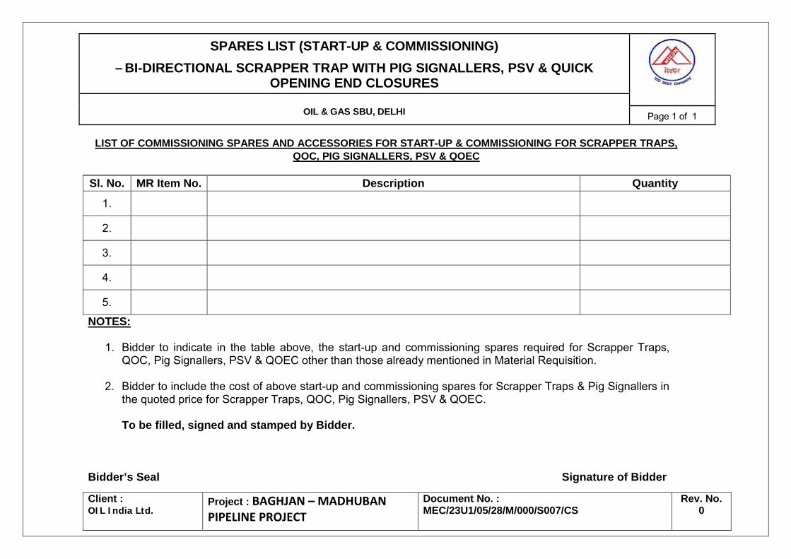
SPARES LIST (START-UP & COMMISSIONING) – BI-DIRECTIONAL SCRAPPER TRAP WITH PIG SIGNALLERS, PSV & QUICK
OPENING END CLOSURES
OIL & GAS SBU, DELHI Page 1 of 1
Client : OIL India Ltd.
Project : BAGHJAN – MADHUBAN PIPELINE PROJECT
Document No. : MEC/23U1/05/28/M/000/S007/CS
Rev. No. 0
LIST OF COMMISSIONING SPARES AND ACCESSORIES FOR START-UP & COMMISSIONING FOR SCRAPPER TRAPS,
1. Bidder to indicate in the table above, the start-up and commissioning spares required for Scrapper Traps, QOC, Pig Signallers, PSV & QOEC other than those already mentioned in Material Requisition.
2. Bidder to include the cost of above start-up and commissioning spares for Scrapper Traps & Pig Signallers in the quoted price for Scrapper Traps, QOC, Pig Signallers, PSV & QOEC.
To be filled, signed and stamped by Bidder.
Bidder’s Seal Signature of Bidder
SPARES LIST (2 YEARS NORMAL OPERATION) – BI-DIRECTIONAL SCRAPPER TRAP WITH PIG SIGNALLERS, PSV & QUICK
OPENING END CLOSURES
OIL & GAS SBU, DELHI Page 1 of 1
Client : OIL India Ltd.
Project : BAGHJAN – MADHUBAN PIPELINE PROJECT
Document No. : MEC/23U1/05/28/M/000/S007/OMS
Rev. No. 0
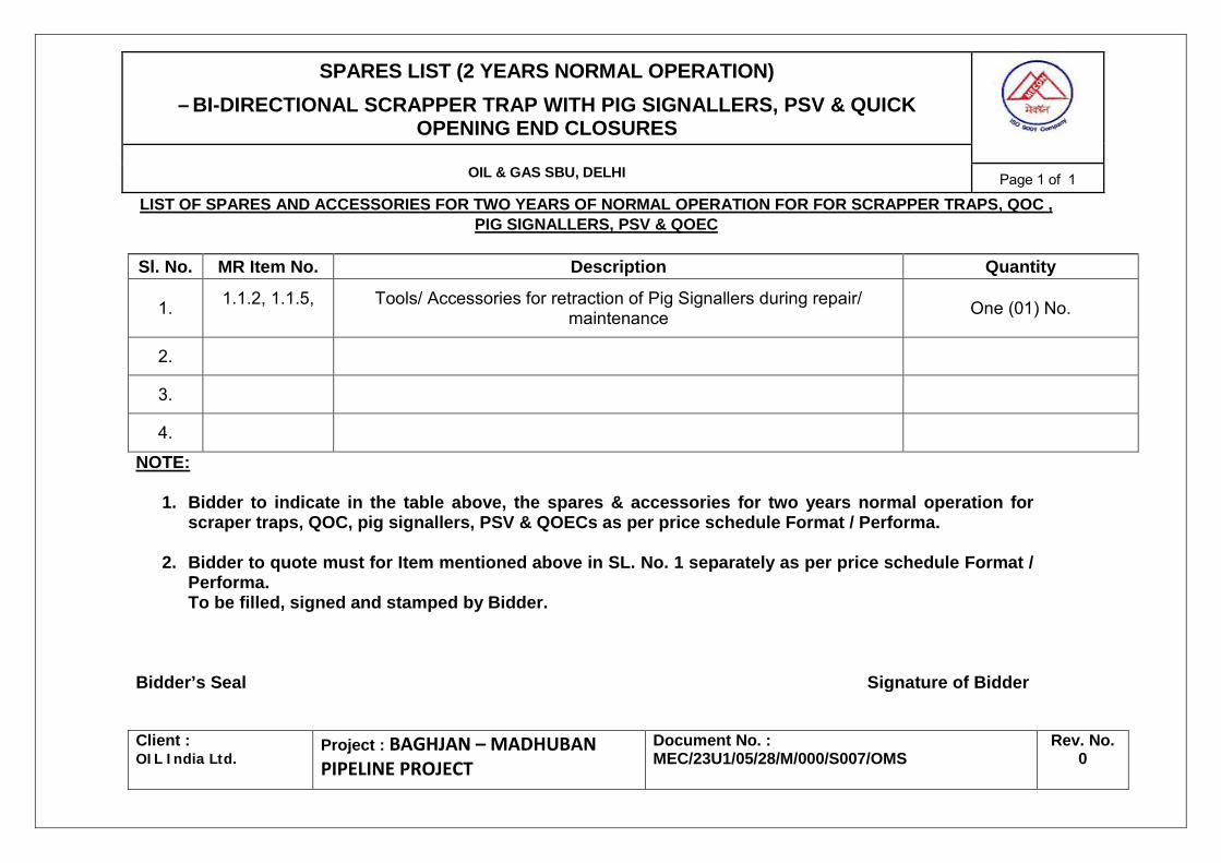
LIST OF SPARES AND ACCESSORIES FOR TWO YEARS OF NORMAL OPERATION FOR FOR SCRAPPER TRAPS, QOC , PIG SIGNALLERS, PSV & QOEC
Sl. No. MR Item No. Description Quantity
1. 1.1.2, 1.1.5,
Tools/ Accessories for retraction of Pig Signallers during repair/ maintenance One (01) No.
2.
3.
4. NOTE:
1. Bidder to indicate in the table above, the spares & accessories for two years normal operation for scraper traps, QOC, pig signallers, PSV & QOECs as per price schedule Format / Performa.
2. Bidder to quote must for Item mentioned above in SL. No. 1 separately as per price schedule Format /
Performa. To be filled, signed and stamped by Bidder.
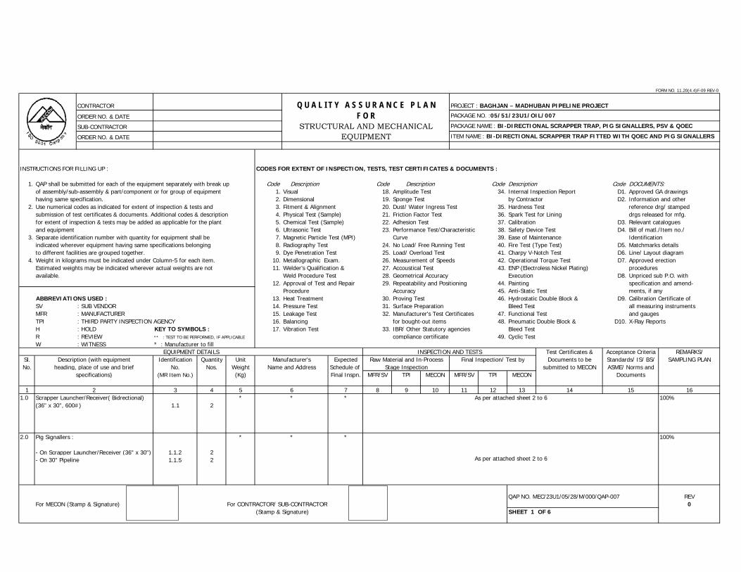
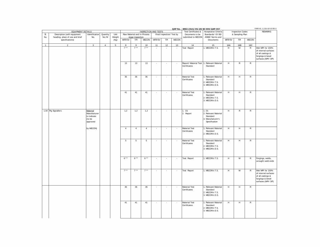
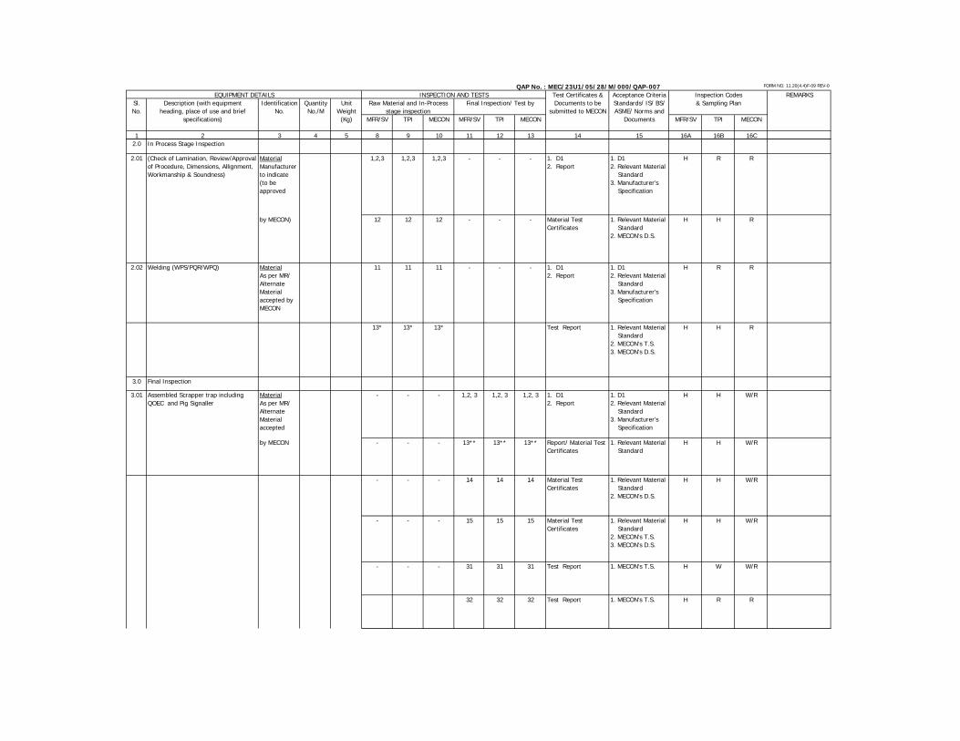
ORDER NO. & DATE ITEM NAME : BI-DIRECTIONAL SCRAPPER TRAP FITTED WITH QOEC AND PIG SIGNALLERS
INSTRUCTIONS FOR FILLING UP : CODES FOR EXTENT OF INSPECTION, TESTS, TEST CERTIFICATES & DOCUMENTS :
1. QAP shall be submitted for each of the equipment separately with break up Code Description Code Code Description Code DOCUMENTS:of assembly/sub-assembly & part/component or for group of equipment 1. Visual 18. Amplitude Test 34. Internal Inspection Report D1. Approved GA drawingshaving same specification. 2. Dimensional 19. Sponge Test by Contractor D2. Information and other
2. Use numerical codes as indicated for extent of inspection & tests and 3. Fitment & Alignment 20. Dust/ Water Ingress Test 35. Hardness Test reference drg/ stampedsubmission of test certificates & documents. Additional codes & description 4. Physical Test (Sample) 21. Friction Factor Test 36. Spark Test for Lining drgs released for mfg.for extent of inspection & tests may be added as applicable for the plant 5. Chemical Test (Sample) 22. Adhesion Test 37. Calibration D3. Relevant cataloguesand equipment 6. Ultrasonic Test 23. Performance Test/Characteristic 38. Safety Device Test D4. Bill of matl./Item no./
3. Separate identification number with quantity for equipment shall be 7. Magnetic Particle Test (MPI) Curve 39. Ease of Maintenance Identification indicated wherever equipment having same specifications belonging 8. Radiography Test 24. No Load/ Free Running Test 40. Fire Test (Type Test) D5. Matchmarks detailsto different facilities are grouped together. 9. Dye Penetration Test 25. Load/ Overload Test 41. Charpy V-Notch Test D6. Line/ Layout diagram
4. Weight in kilograms must be indicated under Column-5 for each item. 10. Metallographic Exam. 26. Measurement of Speeds 42. Operational Torque Test D7. Approved erectionEstimated weights may be indicated wherever actual weights are not 11. Welder’s Qualification & 27. Accoustical Test 43. ENP (Electroless Nickel Plating) proceduresavailable. Weld Procedure Test 28. Geometrical Accuracy Execution D8. Unpriced sub P.O. with
12. Approval of Test and Repair 29. Repeatability and Positioning 44. Painting specification and amend-Procedure Accuracy 45. Anti-Static Test ments, if any
ABBREVIATIONS USED : 13. Heat Treatment 30. Proving Test 46. Hydrostatic Double Block & D9. Calibration Certificate ofSV : SUB VENDOR 14. Pressure Test 31. Surface Preparation Bleed Test all measuring instrumentsMFR : MANUFACTURER 15. Leakage Test 32. Manufacturer's Test Certificates 47. Functional Test and gaugesTPI : THIRD PARTY INSPECTION AGENCY 16. Balancing for bought-out items 48. Pneumatic Double Block & D10. X-Ray ReportsH : HOLD KEY TO SYMBOLS : 17. Vibration Test 33. IBR/ Other Statutory agencies Bleed TestR : REVIEW ** : TEST TO BE PERFORMED, IF APPLICABLE compliance certificate 49. Cyclic Test W : WITNESS * : Manufacturer to fill
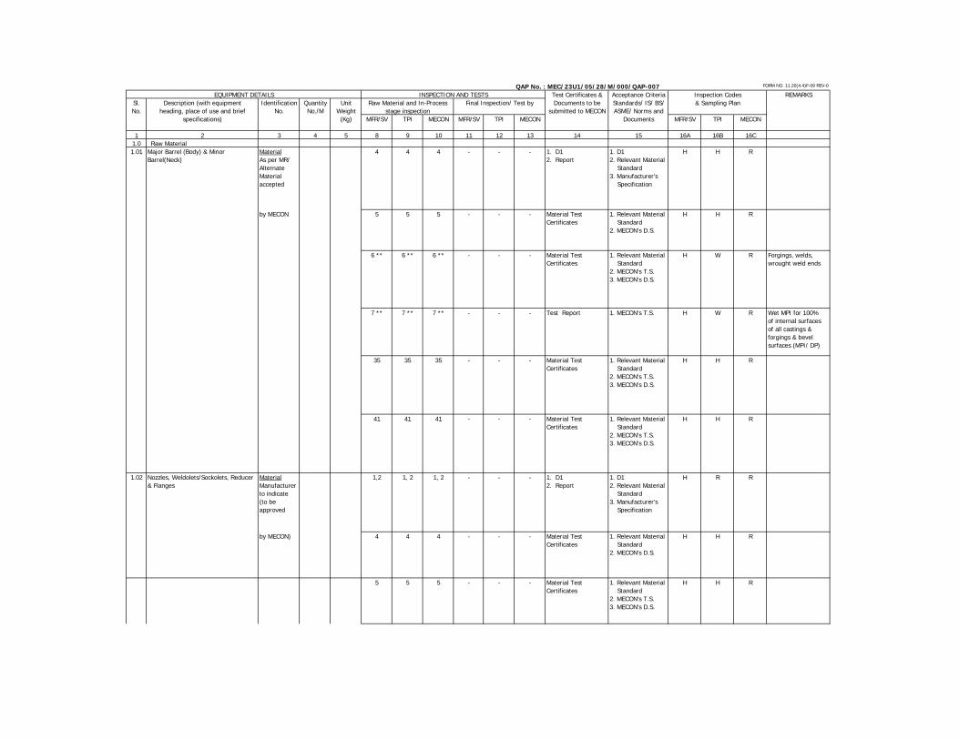
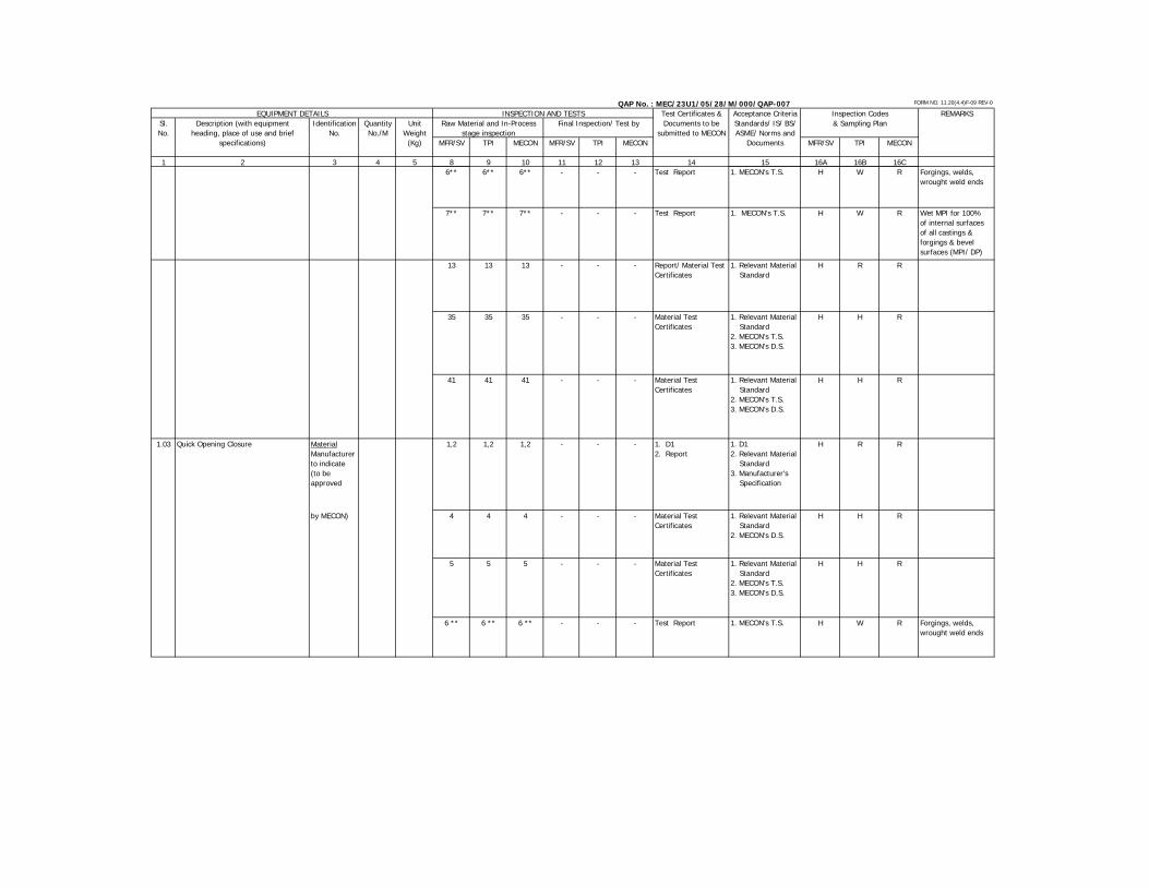
Test Certificates & REMARKS/Sl. Identification Quantity Unit Expected Documents to be SAMPLING PLANNo. No. Nos. Weight Schedule of submitted to MECON
Complete and compiled document check and Despatch Clearance
1. Relevant Material Standard2. MECON's T.S.3. MECON's D.S.
1. Relevant Material Standard2. MECON's T.S.3. MECON's D.S.
1. MECON's T.S.
1. MECON's T.S.
Final Documentation Check, Verification of TC & Compilation of Inspection Reports
FORM NO. 11.20(4.4)F-09 REV-0
CONTRACTOR
ORDER NO. & DATE PACKAGE NO. :05/51/23U1/OIL/007SUB-CONTRACTOR PACKAGE NAME : BI-DIRECTIONAL SCRAPPER TRAP, PIG SIGNALLERS, PSV & QOEC
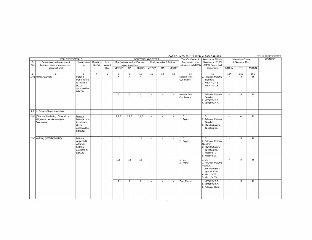
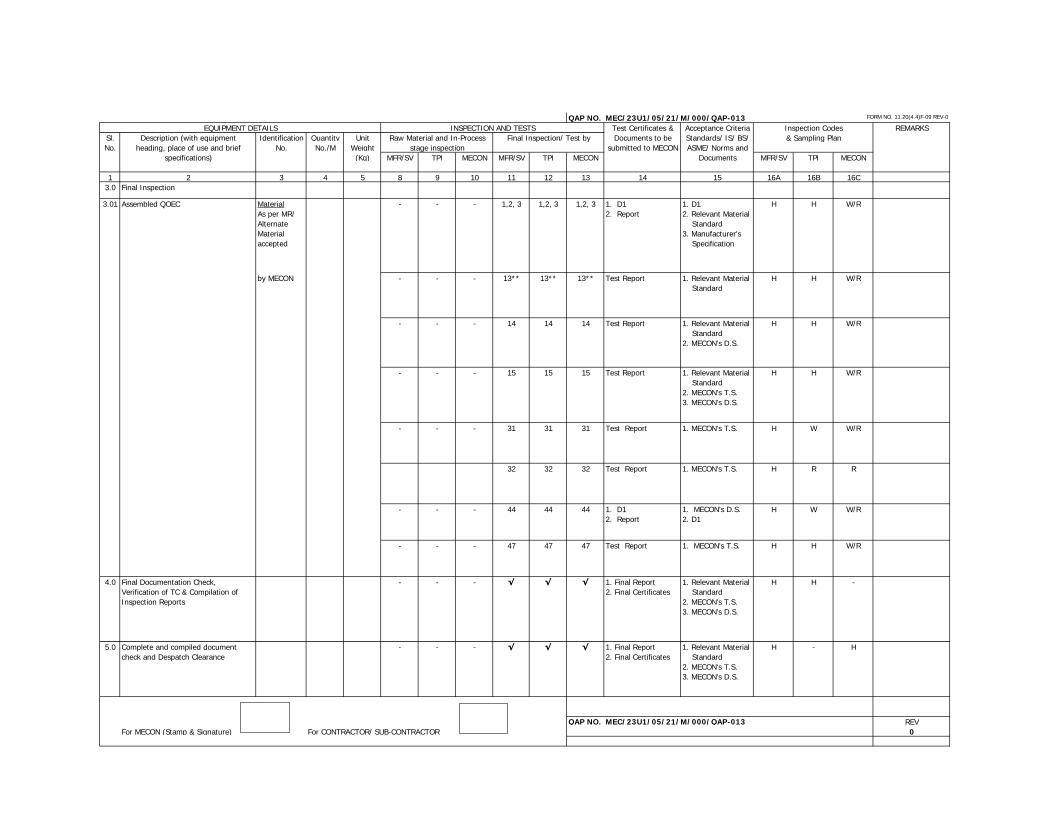
ORDER NO. & DATE ITEM NAME : QOEC (For Blow down Line)
INSTRUCTIONS FOR FILLING UP : CODES FOR EXTENT OF INSPECTION, TESTS, TEST CERTIFICATES & DOCUMENTS :
1. QAP shall be submitted for each of the equipment separately with break up Code Description Code Code Description Code DOCUMENTS:of assembly/sub-assembly & part/component or for group of equipment 1. Visual 18. Amplitude Test 34. Internal Inspection Report D1. Approved GA drawingshaving same specification. 2. Dimensional 19. Sponge Test by Contractor D2. Information and other
2. Use numerical codes as indicated for extent of inspection & tests and 3. Fitment & Alignment 20. Dust/ Water Ingress Test 35. Hardness Test reference drg/ stampedsubmission of test certificates & documents. Additional codes & description 4. Physical Test (Sample) 21. Friction Factor Test 36. Spark Test for Lining drgs released for mfg.for extent of inspection & tests may be added as applicable for the plant 5. Chemical Test (Sample) 22. Adhesion Test 37. Calibration D3. Relevant cataloguesand equipment 6. Ultrasonic Test 23. Performance Test/Characteristic 38. Safety Device Test D4. Bill of matl./Item no./
3. Separate identification number with quantity for equipment shall be 7. Magnetic Particle Test (MPI) Curve 39. Ease of Maintenance Identification indicated wherever equipment having same specifications belonging 8. Radiography Test 24. No Load/ Free Running Test 40. Fire Test (Type Test) D5. Matchmarks detailsto different facilities are grouped together. 9. Dye Penetration Test 25. Load/ Overload Test 41. Charpy V-Notch Test D6. Line/ Layout diagram
4. Weight in kilograms must be indicated under Column-5 for each item. 10. Metallographic Exam. 26. Measurement of Speeds 42. Operational Torque Test D7. Approved erectionEstimated weights may be indicated wherever actual weights are not 11. Welder’s Qualification & 27. Accoustical Test 43. ENP (Electroless Nickel Plating) proceduresavailable. Weld Procedure Test 28. Geometrical Accuracy Execution D8. Unpriced sub P.O. with
12. Approval of Test and Repair 29. Repeatability and Positioning 44. Painting specification and amend-Procedure Accuracy 45. Anti-Static Test ments, if any
ABBREVIATIONS USED : 13. Heat Treatment 30. Proving Test 46. Hydrostatic Double Block & D9. Calibration Certificate ofSV : SUB VENDOR 14. Pressure Test 31. Surface Preparation Bleed Test all measuring instrumentsMFR : MANUFACTURER 15. Leakage Test 32. Manufacturer's Test Certificates 47. Functional Test and gaugesTPI : THIRD PARTY INSPECTION AGENCY 16. Balancing for bought-out items 48. Pneumatic Double Block & D10. X-Ray ReportsH : HOLD KEY TO SYMBOLS : 17. Vibration Test 33. IBR/ Other Statutory agencies Bleed TestR : REVIEW ** : TEST TO BE PERFORMED, IF APPLICABLE compliance certificate 49. Cyclic Test W : WITNESS * : Manufacturer to fill
Test Certificates & REMARKS/Sl. Identification Quantity Unit Expected Documents to be SAMPLING PLANNo. No. Nos. Weight Schedule of submitted to MECON
Complete and compiled document check and Despatch Clearance
1. Relevant Material Standard2. MECON's T.S.3. MECON's D.S.
1. MECON's T.S.
1. Relevant Material Standard2. MECON's D.S.
1. D12. Relevant Material Standard3. Manufacturer's Specification
1. MECON's T.S.
1. MECON's D.S. 2. D1
1. MECON's T.S.
Assembled QOEC
1. Relevant Material Standard2. MECON's T.S.3. MECON's D.S.
1. Relevant Material Standard2. MECON's T.S.3. MECON's D.S.
1. Relevant Material Standard
Final Documentation Check, Verification of TC & Compilation of Inspection Reports
FORM NO. 11.20(4.4)F-09 REV-0
CONTRACTOR
ORDER NO. & DATE BID DOCUMENT NO. :
SUB-CONTRACTOR ITEM NAME : PRESSURE SAFETY VALVE
ORDER NO. & DATE
INSTRUCTIONS FOR FILLING UP : CODES FOR EXTENT OF INSPECTION, TESTS, TEST CERTIFICATES & DOCUMENTS :
1. QAP shall be submitted for each of the equipment separately with break up Code Description Code Code Description Code DOCUMENTS:of assembly/sub-assembly & part/component or for group of equipment 1. Visual 18. Amplitude Test 34. Internal Inspection Report D1. Approved GA drawings
having same specification. 2. Dimensional 19. Sponge Test by Contractor D2. Information and other
2. Use numerical codes as indicated for extent of inspection & tests and 3. Fitment & Alignment 20. Dust/ Water Ingress Test 35. Hardness Test reference drg/ stamped
submission of test certificates & documents. Additional codes & description 4. Physical Test (Sample) 21. Friction Factor Test 36. Spark Test for Lining drgs released for mfg.
for extent of inspection & tests may be added as applicable for the plant 5. Chemical Test (Sample) 22. Adhesion Test 37. Calibration D3. Relevant catalogues
and equipment 6. Ultrasonic Test 23. Performance Test/Characteristic 38. Safety Device Test D4. Bill of matl./Item no./
3. Separate identification number with quantity for equipment shall be 7. Magnetic Particle Test (MPI) Curve 39. Ease of Maintenance Identification
indicated wherever equipment having same specifications belonging 8. Radiography Test 24. No Load/ Free Running Test 40. Fire Test (Type Test) D5. Matchmarks details
to different facilities are grouped together. 9. Dye Penetration Test 25. Load/ Overload Test 41. Charpy V-Notch Test D6. Line/ Layout diagram
4. Weight in kilograms must be indicated under Column-5 for each item. 10. Metallographic Exam. 26. Measurement of Speeds 42. Operational Torque Test D7. Approved erection
Estimated weights may be indicated wherever actual weights are not 11. Welder’s Qualification & 27. Accoustical Test 43. ENP (Electroless Nickel Plating) procedures
available. Weld Procedure Test 28. Geometrical Accuracy Execution D8. Unpriced sub P.O. with
12. Approval of Test and Repair 29. Repeatability and Positioning 44. Painting specification and amend-
Procedure Accuracy 45. Anti-Static Test ments, if any
ABBREVIATIONS USED : KEY TO SYMBOLS : 13. Heat Treatment 30. Proving Test 46. Hydrostatic Double Block & D9. Calibration Certificate of
CONTR : CONTRACTOR * : MFR/ CONTRACTOR - AS APPLICABLE 14. Pressure Test 31. Surface Preparation Bleed Test all measuring instruments
MFR : MANUFACTURER ** : TEST TO BE PERFORMED, IF APPLICABLE 15. Leakage Test 32. Manufacturer's Test Certificates 47. Functional Test and gauges
H : HOLD 16. Balancing for bought-out items 48. Pneumatic Double Block & D10. X-Ray Reports
R : REVIEW 17. Vibration Test 33. IBR/ Other Statutory agencies Bleed Test
W : WITNESS compliance certificate
P : PERFORM
Test Certificates & REMARKS/
SPEC. NO.: MEC/TS/05/62/056, REV-01
Description
Acceptance Criteria
Q U A L I T Y A S S U R A N C E P L A NF O R
STRUCTURAL AND MECHANICAL
EQUIPMENT
EQUIPMENT DETAILS INSPECTION AND TESTS
PROJECT : GAS PIPELINE FROM GGS/EPS BAGHJAN TO CGGS
MADHUBAN,DULIAJAN
Test Certificates & REMARKS/
Sl. Identification Quantity Unit Expected Documents to be SAMPLING PLAN
No. No. No./M Weight Schedule of submitted to MECON
(Kg) Final Inspn. MECON
1 3 4 5 7 9 10 14 16
1,2,3 P 1,2,4 W - 1,2,3 P 1,2,3 W 1,2,3 R 1,2,3,4,5,8,14,15 47
- - - 4,5 P 5,41 W - 14,15 P 14,15 W 14,47 R 31,32,34,41,44,47 100%
8,41 P 8 R 31,32 P 44,47 W
44,47 P 31,32 R
QAP NO. MEC/23U1/05/28/M/001/QAP-056 REV
For MECON (Stamp & Signature) For CONTRACTOR/ SUB-CONTRACTOR 0
(Stamp & Signature) SHEET 1 OF 1
* To be field by party as per index above & approved by MECON