,()/ ,. \.....- ~o/ ?J / Program determines two-phase flow BASIC computer program determines which of seven possible flow patterns a gas-liquid mixture will have as defined by the Baker graph C. E. Yamashiro, lo G. Sala Espiell and 1.H. Farina, IPAKO S.A., Ensenada, Argentina WHEN A MIXTUREof a gas and a liquid flows along a horizontal pipe, it is possible to have up to seven different flow patterns. According to Bakerl these flow patterns are2: 1. Dispersed. When nearly all the liquid is entrained as spray by the gas. 2.. Annular. The liquid forms a film around the inside wall of the pipe, and the gas flows at a high velocity as a central coreo 3. Bubble. Bubbles of gas move along at abolir the same velocity as the liquido 4. Stratified. The liquid flows along the bottom ofthe pipe and the gas flows above ayer a smooth gas-liquid interface. 5. Wave. Is similar to stratified except the interface is dis- turbed by waves moving in the direction of flow. '-'" 6. Slug. Waves are picked up periodically in the form of frothy slugs that llave at a much greater velocity than the average liquid velocity. . 7. Plug. Alternate plugs of liquid and gas llave along the plpe. Bakerl has correlated the seven flow patterns by means of two numbers, the "Baker parameters," Bx and By- Thus the Bx, By plane shows seven regions, one for each flow patterh. Although the borders of the regions are drawn as hiles, they are really broad transition zones. "'-' '- 10,000 cQ 1,000 100 10 100 1,000 10,000 B. Fig. 1-Program's approximation of the Baker graph. Determination of two-phase flow by computar. In a recent paper Soliman3 provided a BASIC program to compute two- ~ phase pressure drop based on the excellent work of Kern.2 To determine the pattern of two-phase flow, Soliman re- duced the Baker graph to four regions instead of the seven found experimentally. This makes the computer program- mirig a great deal easier. However, we think that Ibis is an oversimplification. 46 Hydrocarbon Processing, December 1986 We chose to approximate the boundaries of the Baker graph by eight straight lines, as is shown in Fig. 1. The equa- tions of those hiles are: Cl: lag By = 3.698 - 0.163 lag Bx C2: lag By = 4.261 - 0.642 lag Bx C3: lag By = 4.959 - 0.410 lag Bx C4: lag By = 4.477 C5: lag By = 4.019 - 0.241 lag Bx C6: lag By = 1.935 + 1.057 lag Bx C7: lag By = 6.527 - 1.072 lag Bx C8: lag By = 3.301 - 0.197 lag Bx To simplify the computer programming we divided the " range of Bx into the following five zones: 1. 0.1 < Bx > 4.013 2. 4.013 < Bx > 15.00 3. 15.000 < Bx > 40.322 4. 40.322 < Bx> 143.51 5. 143.51 < Bx:> 10,000 The Baker parameters have the following expressions: Bx = K¡ (WjWc) (VPL PClpL2/3) (ILLl/3IaL) By = K2Wc/(7rD2/4) VPL Pc where: W = flowrate P = density IL = viscosity a = liquid surface tension D = internal diameter of pipe L = liquid G = gas '-'" K1 and K2 are constants that involve the conversion factors of units. Two seIs are included in our program: K¡ = 2.1039 and K2 = 25,524.62 when the units of the-/ data are metric W = Kg/s IL= cp D=m P = Kg/m3 a = dyne/cm K1 = 513 and K2 = 2.16 when the units of the data are English W = lb/h IL= cp D = ft P = Ib/cu3 a = dyne/cm The computar programo Table 1 is a listing of the computer program written in BASIC. It has two options for the input of the data: metric or english units. Table 2 is an example of the program output illustrating one zone in the Baker graph. / We think that the errors in using our approximations are of the same magnitude as the inherent errors of the original Baker graph.
Transcript
,()/
,.
\.....-
~o/?J
/
Program determines two-phase flowBASIC computer program determineswhich of seven possible flow patternsa gas-liquid mixture will have as definedby the Baker graph
C. E. Yamashiro, lo G. Sala Espiell and 1.H. Farina, IPAKOS.A., Ensenada, Argentina
WHEN A MIXTUREof a gas and a liquid flows along ahorizontal pipe, it is possible to have up to seven differentflow patterns. According to Bakerl these flow patterns are2:
1. Dispersed.When nearly all the liquid is entrained asspray by the gas.
2.. Annular.The liquid forms a film around the inside wallof the pipe, and the gas flows at a high velocity as a centralcoreo
3. Bubble. Bubbles of gas move along at abolir the samevelocity as the liquido
4. Stratified. The liquid flows along the bottom ofthe pipeand the gas flows above ayer a smooth gas-liquid interface.
5. Wave. Is similar to stratified except the interface is dis-turbed by waves moving in the direction of flow.
'-'" 6. Slug. Waves are picked up periodically in the form offrothy slugs that llave at a much greater velocity than theaverage liquid velocity.
. 7. Plug. Alternate plugs of liquid and gas llave along theplpe.
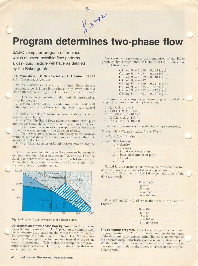
Bakerl has correlated the seven flow patterns by means oftwo numbers, the "Baker parameters," Bx and By- Thus theBx, By plane shows seven regions, one for each flow patterh.Although the borders of the regions are drawn as hiles, theyare really broad transition zones.
"'-'
'-
10,000
cQ
1,000
10010 100 1,000 10,000
B.
Fig. 1-Program's approximation of the Baker graph.
Determination of two-phase flow by computar. In a recentpaper Soliman3 provided a BASIC program to compute two-
~ phase pressure drop based on the excellent work of Kern.2To determine the pattern of two-phase flow, Soliman re-duced the Baker graph to four regions instead of the sevenfound experimentally. This makes the computer program-mirig a great deal easier. However, we think that Ibis is anoversimplification.
46 Hydrocarbon Processing, December 1986
We chose to approximate the boundaries of the Bakergraph by eight straight lines, as is shown in Fig. 1. The equa-tions of those hiles are:
Cl: lag By = 3.698 - 0.163 lag BxC2: lag By = 4.261 - 0.642 lag BxC3: lag By = 4.959 - 0.410 lag BxC4: lag By = 4.477C5: lag By = 4.019 - 0.241 lag BxC6: lag By = 1.935 + 1.057 lag BxC7: lag By = 6.527 - 1.072 lag BxC8: lag By = 3.301 - 0.197 lag Bx
To simplify the computer programming we divided the "range of Bx into the following five zones:
K1 and K2 are constants that involve the conversion factorsof units. Two seIs are included in our program:
K¡ = 2.1039 and K2 = 25,524.62 when the units of the-/data are metric
W = Kg/sIL= cp
D=m
P = Kg/m3a = dyne/cm
K1 = 513 and K2 = 2.16 when the units of the data areEnglish
W = lb/hIL= cp
D = ftP = Ib/cu3a = dyne/cm
The computar programo Table 1 is a listing of the computerprogram written in BASIC. It has two options for the inputof the data: metric or english units. Table 2 is an example ofthe program output illustrating one zone in the Baker graph. /We think that the errors in using our approximations are ofthe same magnitude as the inherent errors of the originalBaker graph.
~~ .., ---
TABLE1,.- 10 REM PROGRAMA "BAKER" EN CINTA 01-F
11 REM IPAKO INe, DE PROCESO -1984-'12 REM20 REM DEFINES THE PRINTER30 PRINTER IS 7,I',WIDTH(76)40 OPTION BASE 150 REM60 REM DATA INPUT70 REM80 INPUT90 INPUT100 INPUT110 INPUT120 INPUT130 INPUT140 INPUT150 INPUT160 REM170 REM DATA PRINTING180 REM190 U$=" METRIC UNITS"200 IF S$="Y" THEN U$=" ENGLISH UNITS"
310 PRINT "LiquId densIty(lb/ft3)"""",320 PRINT "Gas denslty(lb/ft3):""""",330 PRINT "PIpe dIaMeter(lnch): ,340 PRINT "LIquId ulscoslty(cp):"""""350 PRINT "LiquId surface tensIon(dyneslcM)360 PRINT "RESULTS"370 PRINT LIN(1)371 -REM380 REM DEFINES SYSTEM OF UNITS381 REM:\90 IF S$,""Y" THEN 450400 T=T/1000410 VI=V1/1000420 KI=2,1039430 K2=25524,617440 GOTa 480450 K 1"531460 K2=2, 16470 D=D*,08333480 A=PI*D*D/4490 X=K1*(G1/G2)*( (R1*R2)', 5/R1' ,667)* (V1 A, 333/1>500 Y=K2*GU(A*(R1*R2)',5)510 IF X)10000 THEN lOtO520 lF X< ,1 THEN 1010530 IF Y>100000 THEN 1010540 IF yaOO THEN 1010550 L3=LGT< X)560 L4=LGT(y)570 CI=3,6<18-, 163*L:\580 C2=4, 261-, 642*L3590 C3=4,959-,410*L3600 C4=4,477610 C5=4,OI9-,241*L3620 C6=I, 935+1 ,057*L3630 C'7=6, 527-1, 072*L3640 C8=3,301-,197*L3650 IF X)15 THEN 730660 IF L4<CI THEN 870670 IF L4<C2 THEN 890680 IF L4 )C3 THEN 910690 IF X)4,OI:! THEN 710700 GOTa 950710 IF L4<C5 THEN 930720 GOTa 950730 IF L4< C2 THEN 870740 IF X>143,51 THEN 810750 IF L4)C4 THEN 910760 IF X )40 -322 THEN 790770 IF L4)C5 THEN 950780 GOTa 930790 IF L4)C6 THEN 950800 GOTa 930810 IF L4)C7 THEN 970820 IF L4 )C8 THEN 930830 GOTa 990840 REM850 REM RESUL TS860 REM870 PRINT "ESTRATIFIED"880 GOTa 1020890 PRINT "WAVE"90 O GOTa 1 020910 PRINT "DISPERSE"920 GOTa 1020930 PRINT "SLUG"940 GOTa 1020950 PRINT "ANNULAR"960 GOTa 1 020970 PR INT "BUBBLE"980 GOTa 1020990 PRINT "PLUG"1000 GOTa 10201010 PRINT "DATA OUTSIDE BAKER GRAPH"1020 PRINT "X: , "¡X1030 PRINT "Y: " " ".., "¡Y1031 PRINT LIN(4)1040 END
Although the program was originally written for a HP-9835 and IBM PC, we rewrote it in a version simple enoughto run in most personal computers. It is easily converted to asubroutine by changing the GOTO 1020's to RETURN's.
LITERATURE CITED
: Baker,0., GilandGasJournal,July 26, 1954.:Kern, R., Hydrocarbon Processing, Vol. 48, No. 10, October 1969, pp. 105-116.3'Soliman, R., Hydrocarbon Processing, Vol. 63, No. 4, April, 1984, pp. 155-157.
The authors
Carlos E. Yamashiro is a process engineer with IPAKO S.A., En-senada, Argentina. He is responsible for optimization and trouble-shooting of the high pressure PEplant. He holds a as degree in chemi-cal engineering from the University of La Plata.
Luis G. Sala Espiell is a computar analyst with IPAKO S.A., En-senada, Argentina. He is engaged in developing software for engineer-ing needs, assisting the computar users and studying computar con-trol problems. He holds a as degree in electronic engineering from theUniversity of La Plata.
Italo H. Farina is a process engineering superintendent for IPAKOS.A., Ensenada, Argentina. He is responsible for supervising the pro-cess engineering of ethylene and PE plants and developing computarresources for engineering. He is a part-time professor of chemical en-gineering at the University of La Plata, Argentina. He holds a as de-gree from the University of La Plata and an MS degree fram the Univer-sity of Minnesota, both in chemical engineering.


![On two-phase flow models for Coriolis flowmetersflomeko2019.lnec.pt/proceedings/1033 Xiao Zhang.pdf · [2] Wang T, Baker RC, Coriolis flowmeters: a review of developments over the](https://static.documents.pub/doc/80x56/5e61d57d13d7314f5018847b/on-two-phase-flow-models-for-coriolis-f-xiao-zhangpdf-2-wang-t-baker-rc-coriolis.jpg)


