KOSOVO TEL: +381 38 59 58 313 Pristina International Airport FAX: +381 38 59 58 214 AFTN: BKPRZPZX CIVIL AVIATIONAUTHORITY 13/2014 Publication date: 12 JUN 2014 Vrellë-Lipjan E-mail: [email protected]2. Please record entry of Amendment on page GEN 0.2-1 Remove the following old page 1. Insert the following new page AMDT Aeronautical Information Service AIP AIP Effective date: 24 JUL 2014 AIRAC 24 JUL 14 24 JUL 14 24 JUL 14 24 JUL 14 24 JUL 14 24 JUL 14 24 JUL 14 24 JUL 14 24 JUL 14 24 JUL 14 ENR 1.6-1/2 BKPR AD 2.1-5/6 BKPR AD 2.1-9/10 BKPR AD 2.1-11/12 BKPR AD 2.1-13/14 BKPR AD 2.1-15/16 BKPR AD 2.1-17/18 BKPR AD 2.1-19/20 BKPR AD 2.24.1.1-1 BKPR AD 2.24.2.1-1 ENR 1.6-1/2 BKPR AD 2.1-5/6 BKPR AD 2.1-9/10 BKPR AD 2.1-11/12 BKPR AD 2.1-13/14 BKPR AD 2.1-15/16 BKPR AD 2.24.1.1-1 BKPR AD 2.24.2.1-1 03 APR 14 12 DEC 13 03 APR 14 03 APR 14 03 APR 14 14 JUN 12 12 DEC 13 12 DEC 13
ENR 1.6-1/2BKPR AD 2.1-5/6BKPR AD 2.1-9/10BKPR AD 2.1-11/12BKPR AD 2.1-13/14BKPR AD 2.1-15/16BKPR AD 2.1-17/18BKPR AD 2.1-19/20BKPR AD 2.24.1.1-1BKPR AD 2.24.2.1-1
ENR 1.6-1/2BKPR AD 2.1-5/6BKPR AD 2.1-9/10BKPR AD 2.1-11/12BKPR AD 2.1-13/14BKPR AD 2.1-15/16
BKPR AD 2.24.1.1-1BKPR AD 2.24.2.1-1
03 APR 1412 DEC 1303 APR 1403 APR 1403 APR 1414 JUN 12
12 DEC 1312 DEC 13
ENR 1.6 - 1AIP KOSOVO
CIVIL AVIATION AUTHORITY
ENR 1.6 RADAR SERVICES AND PROCEDURES
1.6.1 Primary radar
1.6.1.1 Supplementary services
1.6.1.1.1 A radar unit normally operates as an integralpart of the parent ATS unit and provides radar serviceto aircraft, to the maximum extent practicable, to meetthe operational requirement. Many factors, such asradar coverage, controller workload and equipmentcapabilities, may affect these services, and the radarcontroller shall determine the practicability of providingor continuing to provide radar services in any specificcase.
1.6.1.1.2 Radar Coverage
a. Pristina Approach operates terminal area surveillanceradar station at Golesh Hill location 42°34’01.884’’N20°59’18.733’’E. The radar coverage for secondary ra-dar is 180NM.
b. A pilot will know when radar services arebeing provided because the radar controller will use thephraseology “a/c call sign identified” for aircraftunder approach control.
1.6.1.2 The application of radar control service
1.6.1.2.1 Radar identification is achieved accordingto the provisions specified by ICAO.
1.6.1.2.2 Radar control service is provided incontrolled airspaces to aircraft operating within theKosovo airspace. This service may include:
a) radar separation of arriving, departing anden-route traffic;
b) radar monitoring of arriving, departingand en-route traffic to provideinformation on any significantdeviation from the normal flight path;
c) radar vectoring when required;
d) assistance to aircraft in emergency;
e) assistance to aircraft crossing controlledairspace;
f) warnings and position information onother aircraft considered to constitute ahazard;
g) information to assist in the navigation ofaircraft;
h) information on observed weather.
1.6.1.2.3 The minimum horizontal radar separation is10 NM at or below FL 205
1.6.1.2.4 Levels assigned by the radar controller to
pilots will provide a minimum terrain clearance accordingto the phase of flight.
1.6.1.3 Radar and radio failure procedures
1.6.1.3.1 Radar failure. In the event of radar failure orloss of radar identification, instructions will be issuedto restore non-radar standard separation and the pilotwill be instructed to communicate with the parent ATSunit.
1.6.1.3.2 Radio failure. The radar controller willestablish whether the aircraft radio receiver is workingby instructing the pilot to carry out a turn or turns. Ifthe turns are observed, the radar controller will continueto provide radar service to the aircraft.
1.6.1.3.3 If the aircraft’s radio is completelyunserviceable, the pilot should carry out the proceduresfor radio failure in accordance with ICAO provisions.If radar identification has already been established, theradar controller will vector other identified aircraft clearof its track until such time as the aircraft leaves radarcover.
1.6.2 Secondary surveillance radar (SSR)
1. Operating Procedures
a. Radar service increases airspace utilization byallowing ATC to reduce separation betweenaircraft. In addition, radar permits an exception offlight information services, such as traffic information,and radar navigation assistance. Dueto limitations inherent in all radar systems, it maynot always be possible to detect weatherdisturbance .
Where radar information is derived fromSecondary Surveillance Radar (SSR) only, (i.e.without associated primary radar coverage), it isnot possible to provide traffic information onaircraft that are not transponder equipped or toprovide some of the other flight information.
b. The SSR systems are to be considered as asupplement to the basic procedural system in thePristina Approach and will be used to provideradar separation where benefits to aircraft, safetyor expedition can be obtained. Non-availability ofSSR-data will therefore not cause APP inabilityto perform its stated functions, but may degradethe quality of the service rendered. No radarmaneuver should be undertaken unless it isassured that it will be completed and procedural
24 JUL 2014
AIRAC AMDT 13/14
AIP KOSOVOENR 1.6 - 2
CIVIL AVIATION AUTHORITY
separation re-established whilst any aircraftinvolved remains within radar coverage. It isintended to operate the SSR-system on H24 basis, asfar as possible.c. Except as provided for in para 1.6.2.1 below,pilots shall operate transponders and selectModes and Codes in accordance with ATCinstructions. In particular, when entering thePristina CTA, and flying within radar coverage, pilotswho have already received specific instructions fromATC concerning the setting of the transponder shallmaintain that setting until otherwise instructed.
d. Pilots of aircraft about to enter the PristinaCTA, and will be flying within radar coverage,and have not received specific instructions fromATC concerning the setting of the transpondershall operate the transponder on Mode C Code2000 upon entry and maintain that Code settinguntil otherwise instructed.
e. Before providing radar service, ATC will establishidentification in accordance with ICAO PANS ATMChapter 8. Pilots will be notified whenever radaridentification is established, or lost. Examples:“IDENTIFIED”, OR “IDENTIFICATION LOST”.
f. Pilots are cautioned that radar identification oftheir flight does not relieve them of the responsibilityfor collision avoidance of terrain(obstacle) clearance. ATC will normally provideradar identified IFR flights with relevant information onobserved targets. If the PSR part ofradar system is not functioning, ATC cannot providetraffic information on aircraft without a functioningtransponder. The responsibility for terrain (obstacle)clearance is only accepted by ATC when vectoring IFRflights.
g. Radar vectoring is used when necessary forseparation purposes, when required by noiseabatement procedures, when requested by thepilot, or whenever vectoring will offer operationaladvantages to the pilot or the controller. Whenvectoring is initiated, the pilot will be informed ofthe location to which the aircraft is beingvectored, or the purpose of the vector, e.g. forspacing or weather information.
Examples: “TURN RIGHT HEADING 220 TO INTER-CEPT RADIAL 189 TO SARAX”“FLY HEADING 350 VECTORS TO INTERCEPTRADIAL 017.”“JOIN XAXAN 17A ARRIVAL ”
h. Pilots will be informed when radar vectoring is
terminated.
Example: “RADAR VECTORING TERMINATED.RESUME OWN NAVIGATION.”
i. Normally radar service will be continued until anaircraft leaves the area of radar coverage, entersuncontrolled airspace, or is transferred to an ATCunit not equipped with radar. When radar serviceis terminated the pilot will be informed accordingly.Example: “RADAR SERVICE TERMINATED.RESUME OWN NAVIGATION.”
j. Aircraft on radar vector will be vectored to apublished instrument approach aid, a Localizer(LLZ) course, a VOR Radial/DME, NDB for finalapproach or to a position for visual approach.
k. Radar approach controllers will provide vectorsonto final, onto LLZ course or Radial/DME asfollows:
Pristina: Normally not closer than 10 NM, bothrunways (or as requested by pilots).
2. Radar Traffic Information
a. Traffic (or workload) permitting, ATC willprovide IFR flights with information on observedradar targets whenever the traffic is likely to be ofconcern to the pilot, unless the pilot states that hedoes not want the information. This informationmay be provided to VFR traffic when requested bythe pilot.
b. If requested by the pilot, ATC will attempt toprovide radar separation between identified IFRaircraft and the unknown observed aircraft.
c. When issuing radar information, ATC willfrequently define the relative location of traffic,weather areas, etc., by referring to the “clock”position system. In this system the 12 o’clockposition is based on the observed radar trackrather than the actual nose of the aircraft. Inconditions of strong crosswind this can lead to adiscrepancy between the position as reported bythe controller and the position by the pilot.
d. The following diagram illustrates the “clock”system:
24 JUL 2014
AIRAC AMDT 13/14
AIP KOSOVO AD 2.1 - 5
CIVIL AVIATION AUTHORITY
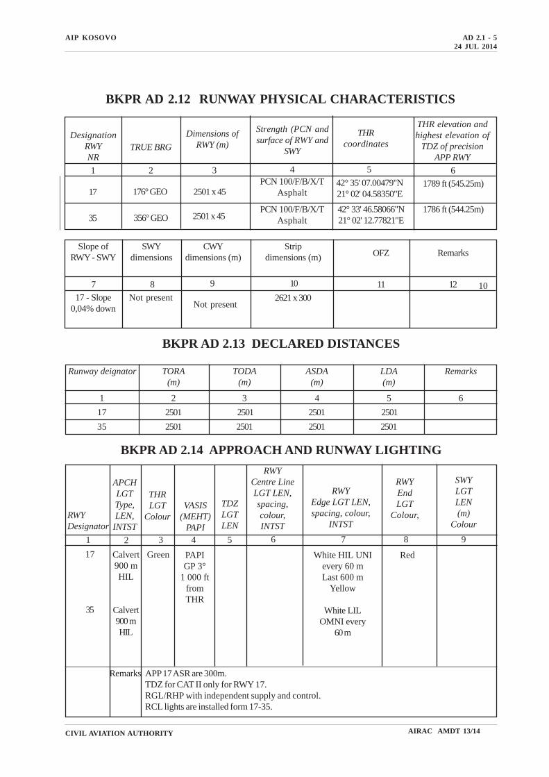
BKPR AD 2.13 DECLARED DISTANCES
Runway deignator TORA(m)
TODA(m)
ASDA(m)
LDA(m)
Remarks
2 3 4 5 6
17 2501
1
2501
2501
2501
2501
2501
2501
250135
RWYDesignator
BKPR AD 2.14 APPROACH AND RUNWAY LIGHTING
APCHLGTType,LEN,
INTST
THRLGT
ColourVASIS
(MEHT)PAPI
TDZLGTLEN
RWYCentre LineLGT LEN,spacing,colour,INTST
RWYEdge LGT LEN,spacing, colour,
INTST
RWYEndLGT
Colour,
SWYLGTLEN(m)
Colour
1 2 3 4 5 6 7 8 9
17
35
Calvert900 mHIL
Calvert900 mHIL
Green PAPIGP 3°
1 000 ftfromTHR
White HIL UNIevery 60 mLast 600 m
Yellow
White LILOMNI every
60 m
Red
24 JUL 2014
Remarks APP 17 ASR are 300m.TDZ for CAT II only for RWY 17.RGL/RHP with independent supply and control.RCL lights are installed form 17-35.
BKPR AD 2.12 RUNWAY PHYSICAL CHARACTERISTICS
DesignationRWYNR
THR elevation andhighest elevation of
TDZ of precisionAPP RWY
TRUE BRG
Dimensions ofRWY (m)
Strength (PCN andsurface of RWY and
SWY
THRcoordinates
1 2 3 4 5 6
17 176° GEO 2501 x 45PCN 100/F/B/X/T
Asphalt42° 35' 07.00479"N21° 02' 04.58350"E
1789 ft (545.25m)
35 356° GEO 2501 x 45PCN 100/F/B/X/T
Asphalt42° 33' 46.58066"N21° 02' 12.77821"E
1786 ft (544.25m)
Slope ofRWY - SWY
SWYdimensions
CWYdimensions (m)
Stripdimensions (m) OFZ Remarks
7 8 9 10 11 12
17 - Slope0,04% down
Not present 2621 x 300 10
Not present
AIRAC AMDT 13/14
AIP KOSOVOAD 2.1 - 6
CIVIL AVIATION AUTHORITY
BKPR AD 2.17 ATS AIRSPACE
Vertical limits GND to 5 000 ft AMSLAirspace classification DATS unit call sign Pristina Approach / Pristina TowerLanguage(s) EnglishTransition altitude 10 000 ft AMSLRemarks Nil
1
234
56
24 JUL 2014
BKPR AD 2.16 HELICOPTER LANDING AREA
Coordinates TLOF or THR of FATOTLOF and/or FATO elevation m/ftTLOF and FATO area dimensions, surface, strengthmarkingTrue and MAG BRG of FATODeclared distance availableAPP and FATO lightingRemarks
123
4567
NilNilNil
NilNilNilHelicopters landing with PPR 24 hours to Base OPSonly. Helicopters shall land in accordance with ATCinsstruction. Presence of Military/UN helicopters on thetaxiways.
PRISTINA CTR
424308N 0205254E - ARC 11DME FROM PRT,
FROM R320 TO R200 CLOCKWISE
422413N 0205605E - 423230N 0210049E - ARC
2DME FROM PRT FROM R200 TO R320 CLOCKWISE
- 423557N 0210015E 424308N 0205254E
Designation and lateral limits
AIRAC AMDT 13/14
BKPR AD 2.15 OTHER LIGHTING SECONDARY POWER SUPPLY
ABN/IBN location, characteristics and hours ofoperationLDI location and LGTAnemometer location and LGTTWY edge and centre line lighting
Mid Runway/Light providedBlue taxiway edge lightingPower source is on two site diesel generators provided withautomatic switch over timeTwo lighted WDI.
AIP KOSOVO AD 2.1 - 9
CIVIL AVIATION AUTHORITY
24 JUL 2014
AIRAC AMDT 13/14
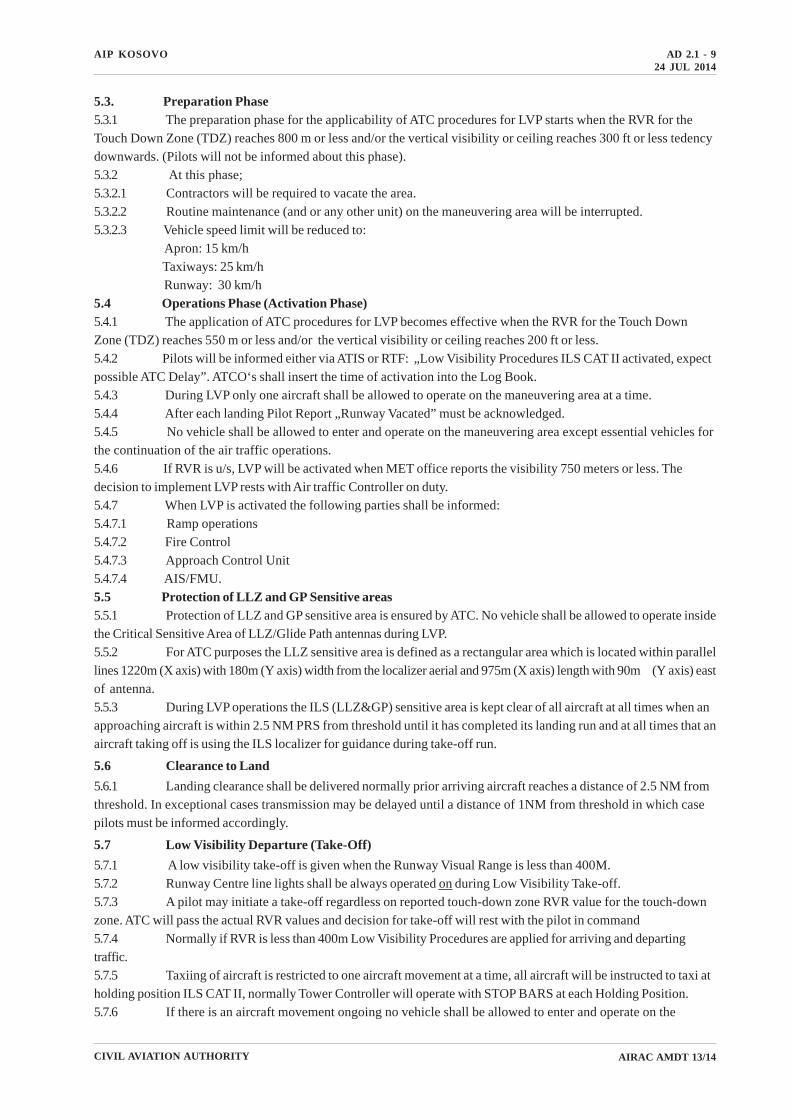
5.3. Preparation Phase5.3.1 The preparation phase for the applicability of ATC procedures for LVP starts when the RVR for theTouch Down Zone (TDZ) reaches 800 m or less and/or the vertical visibility or ceiling reaches 300 ft or less tedencydownwards. (Pilots will not be informed about this phase).5.3.2 At this phase;5.3.2.1 Contractors will be required to vacate the area.5.3.2.2 Routine maintenance (and or any other unit) on the maneuvering area will be interrupted.5.3.2.3 Vehicle speed limit will be reduced to:
Apron: 15 km/h Taxiways: 25 km/h Runway: 30 km/h
5.4 Operations Phase (Activation Phase)5.4.1 The application of ATC procedures for LVP becomes effective when the RVR for the Touch DownZone (TDZ) reaches 550 m or less and/or the vertical visibility or ceiling reaches 200 ft or less.5.4.2 Pilots will be informed either via ATIS or RTF: „Low Visibility Procedures ILS CAT II activated, expectpossible ATC Delay”. ATCO‘s shall insert the time of activation into the Log Book.5.4.3 During LVP only one aircraft shall be allowed to operate on the maneuvering area at a time.5.4.4 After each landing Pilot Report „Runway Vacated” must be acknowledged.5.4.5 No vehicle shall be allowed to enter and operate on the maneuvering area except essential vehicles forthe continuation of the air traffic operations.5.4.6 If RVR is u/s, LVP will be activated when MET office reports the visibility 750 meters or less. Thedecision to implement LVP rests with Air traffic Controller on duty.5.4.7 When LVP is activated the following parties shall be informed:5.4.7.1 Ramp operations5.4.7.2 Fire Control5.4.7.3 Approach Control Unit5.4.7.4 AIS/FMU.5.5 Protection of LLZ and GP Sensitive areas5.5.1 Protection of LLZ and GP sensitive area is ensured by ATC. No vehicle shall be allowed to operate insidethe Critical Sensitive Area of LLZ/Glide Path antennas during LVP.5.5.2 For ATC purposes the LLZ sensitive area is defined as a rectangular area which is located within parallellines 1220m (X axis) with 180m (Y axis) width from the localizer aerial and 975m (X axis) length with 90m (Y axis) eastof antenna.5.5.3 During LVP operations the ILS (LLZ&GP) sensitive area is kept clear of all aircraft at all times when anapproaching aircraft is within 2.5 NM PRS from threshold until it has completed its landing run and at all times that anaircraft taking off is using the ILS localizer for guidance during take-off run.
5.6 Clearance to Land
5.6.1 Landing clearance shall be delivered normally prior arriving aircraft reaches a distance of 2.5 NM fromthreshold. In exceptional cases transmission may be delayed until a distance of 1NM from threshold in which casepilots must be informed accordingly.
5.7 Low Visibility Departure (Take-Off)
5.7.1 A low visibility take-off is given when the Runway Visual Range is less than 400M.5.7.2 Runway Centre line lights shall be always operated on during Low Visibility Take-off.5.7.3 A pilot may initiate a take-off regardless on reported touch-down zone RVR value for the touch-downzone. ATC will pass the actual RVR values and decision for take-off will rest with the pilot in command5.7.4 Normally if RVR is less than 400m Low Visibility Procedures are applied for arriving and departingtraffic.5.7.5 Taxiing of aircraft is restricted to one aircraft movement at a time, all aircraft will be instructed to taxi atholding position ILS CAT II, normally Tower Controller will operate with STOP BARS at each Holding Position.5.7.6 If there is an aircraft movement ongoing no vehicle shall be allowed to enter and operate on the
AIP KOSOVOAD 2.1 - 10
CIVIL AVIATION AUTHORITY
24 JUL 2014
AIRAC AMDT 13/14
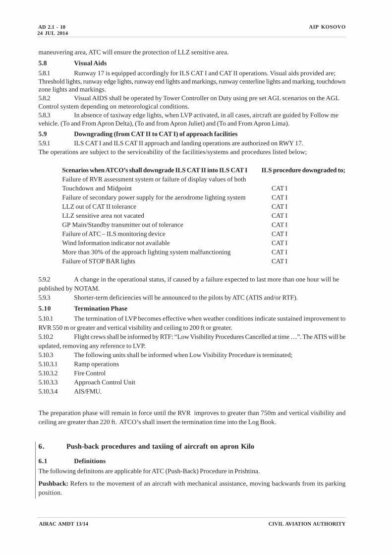
maneuvering area, ATC will ensure the protection of LLZ sensitive area.
5.8 Visual Aids
5.8.1 Runway 17 is equipped accordingly for ILS CAT I and CAT II operations. Visual aids provided are;Threshold lights, runway edge lights, runway end lights and markings, runway centerline lights and marking, touchdownzone lights and markings.5.8.2 Visual AIDS shall be operated by Tower Controller on Duty using pre set AGL scenarios on the AGLControl system depending on meteorological conditions.5.8.3 In absence of taxiway edge lights, when LVP activated, in all cases, aircraft are guided by Follow mevehicle. (To and From Apron Delta), (To and from Apron Juliet) and (To and From Apron Lima).
5.9 Downgrading (from CAT II to CAT I) of approach facilities
5.9.1 ILS CAT I and ILS CAT II approach and landing operations are authorized on RWY 17.The operations are subject to the serviceability of the facilities/systems and procedures listed below;
Scenarios when ATCO’s shall downgrade ILS CAT II into ILS CAT I ILS procedure downgraded to;Failure of RVR assessment system or failure of display values of bothTouchdown and Midpoint CAT IFailure of secondary power supply for the aerodrome lighting system CAT ILLZ out of CAT II tolerance CAT ILLZ sensitive area not vacated CAT IGP Main/Standby transmitter out of tolerance CAT IFailure of ATC – ILS monitoring device CAT IWind Information indicator not available CAT IMore than 30% of the approach lighting system malfunctioning CAT IFailure of STOP BAR lights CAT I
5.9.2 A change in the operational status, if caused by a failure expected to last more than one hour will bepublished by NOTAM.5.9.3 Shorter-term deficiencies will be announced to the pilots by ATC (ATIS and/or RTF).
5.10 Termination Phase
5.10.1 The termination of LVP becomes effective when weather conditions indicate sustained improvement toRVR 550 m or greater and vertical visibility and ceiling to 200 ft or greater.5.10.2 Flight crews shall be informed by RTF: “Low Visibility Procedures Cancelled at time …”. The ATIS will beupdated, removing any reference to LVP.5.10.3 The following units shall be informed when Low Visibility Procedure is terminated;5.10.3.1 Ramp operations5.10.3.2 Fire Control5.10.3.3 Approach Control Unit5.10.3.4 AIS/FMU.
The preparation phase will remain in force until the RVR improves to greater than 750m and vertical visibility andceiling are greater than 220 ft. ATCO’s shall insert the termination time into the Log Book.
6. Push-back procedures and taxiing of aircraft on apron Kilo
6.1 Definitions
The following definitons are applicable for ATC (Push-Back) Procedure in Prishtina.
Pushback: Refers to the movement of an aircraft with mechanical assistance, moving backwards from its parkingposition.
AIP KOSOVO AD 2.1 - 11
CIVIL AVIATION AUTHORITY
24 JUL 2014
AIRAC AMDT 13/14
Ready for Push-Back: All passengers on board, doors closed, pushback tractor is connected with the aircraft, Headsetoperator is in the ready position and in contact with the captain.
Anti collision light: When anti collision light of the aircraft are on, no movement (vehicle nor person) is permittedbehind the aircraft
6.2 General
Aircraft parked on Apron “Kilo”, will be parked with nose pointing towards, direction terminal building. Pushback ofthe aircraft shall be conducted in accordance with the procedures described hereunder, in order to prepare the aircraftfor further taxi manoeuvres.
Airport Dispatch - OCC (Operations Control Centre) assigns aircraft position on the apron. Pilots are informed aboutthe assigned parking position by the station providing Ground Movement Control via radio (Prishtina Ground).
In apron Kilo, aircraft will be parked using VDGS on Stands 201A, 201, 201B, 202A, 202, 202B, 203A 203 and 203B. Instands 101A, 101 and 101B aircraft with be parked using marshaller. In case of VDGS failure, marrshaller is available ateach stand.
All instructions and comunications which are not understood, not clear, not adhered or are interrupted or delayed forany reason must be relayed to ATC.
No aircraft pushback shall take place onto a stand or taxiway / taxiline without the express permission of ATC.
Pilots are reminded that control of aircraft requiring start-up or push back clearance on the aprons is the responsibilityof ATC, and the control of vehicles and personnel is the responsibility of the Airport Operator. Instructions to aircraftare given on the understanding that separation between aircraft and vehicles / personnel on the apron is not theresponsibility of ATC.
Pilots should be cautious whilst manoeuvring on aprons and be aware that they are crossing service roads wherevehicle and personnel are moving at times which are not under ATC responsibility.
When runway 17 is in use, ATC will issue instructions for an aircraft to be pushed back, facing north.
When runway 35 is in use, ATC will issue instructions for an aircraft to be pushed back, facing south.
6.3.1 Restrictions
Stand 101A - can be pushed back facing SOUTH only.
Stand 201B - can be pushed back facing NORTH only, if an aircraft is being deiced on apron “M”
Two aircraft may be cleared for simultaneous pushback if they are separated by at least 2 stands in between them.
(See Table 1 & 2)
AIP KOSOVOAD 2.1 - 12
CIVIL AVIATION AUTHORITY
Stand
201B
201A
202B
202A
203B
203A
101B
101A*
201B 201A 202B 202A 203B 203A 101B 101A*
N/A N N Y Y Y Y N/A
N N/A N N Y Y Y N/A
N
Y
Y
Y
Y
N/A
N
N
Y
Y
Y
N/A
N/A
N
N
Y
Y
N/A
N
N/A
N
N
Y
N/A
N
N
N/A
N
N
N/A
Y
N
N
N/A
N
N/A
Y
Y
N
N
N/A
N/A
N/A
N/A
N/A
N/A
N/A
N/A
Facing NORTH
Stand
201B*
201A
202B
202A
203B
203A
101B
101A
201B* 201A 202B 202A 203B 203A 101B 101A
N/A N N Y Y Y Y Y
N N/A N N Y Y Y Y
N
Y
Y
Y
Y
Y
N
N
Y
Y
Y
Y
N/A
N
N
Y
Y
Y
N
N/A
N
N
Y
Y
N
N
N/A
N
N
Y
Y
N
N
N/A
N
N
Y
Y
N
N
N/A
N
Y
Y
Y
N
N
N/A
*101A can be pushed back facing SOUTH only
Table 1. Simultaneous operations in Apron Kilo (pushback and taxi in) facing north
*Push back facing south from stand 201B shall not be applied if there is an aircraft on Apron“M”
Table 2. Simultaneous operations in Apron Kilo (pushback and taxi in) facing south
Facing SOUTH
24 JUL 2014
AIRAC AMDT 13/14
AIP KOSOVO AD 2.1 - 13
CIVIL AVIATION AUTHORITY
6.4 Non - standard pushback
Simultaneous pushback on opposite directions, one aircraft facing south and another facing north (tail to tail) may beapplied provided that they are seperated by at least 4 stands in between them.Simultaneous push backs on opposite directions (head to head) are not allowed.
Stand
201B
201A
202B
202A
203B
203A
101B
101A
201B 201A 202B 202A 203B 203A 101B 101A
N/A N N N N Y Y Y
N N/A N N N N Y Y
N
N
N
Y
Y
Y
N
N
N
N
Y
Y
N/A
N
N
N
N
Y
N
N/A
N
N
N
N
N
N
N/A
N
N
N
N
N
N
N/A
N
N
N
N
N
N
N/A
N
Y
N
N
N
N
N/A
In exception of the above rule and in order to optimise the movement of traffic on the apron Kilo, simultaneouspushback from Stand 201B and 202B may be approved, provided that aircraft on Stand 201B is pushed back to ApronMike facing south (and no aircraft is being de-iced in apron Mike), while aircraft on Stand 202B is pushed back,facing north. This way both aircraft will use taxiway B2 to exit apron Kilo. If required, a third pushback can take placesimultaneously from stand 203A, 101B or 101A.
6.4.1 Restriction:
For aircraft category E, stands 201, 202, and 203, no simultaneous push- backs allowed.
One aircraft facing NORTH and One aircraft facig SOUTH
Table 3. Simultaneous pushback in Apron Kilo (tail to tail)
Tail to Tail
6.5 Procedure
PiC (Pilot in Command) will assess the situation when he is ready for push-back.
When the PiC is ready for start up and pushback he shall seek confirmation from the Headset Operator that there isno hazard to his aircraft starting up.
Headset Operator must ensure that the area is clear of any obstruction or FOD risk, including staff, passengers,vehicles, equipment and aircraft, before giving clearance for engine start or pushback.Pushback clearance must not be requested by PiC until the Headset Operator has confirmed to the PiC that theaircraft and ground crew are ready for Pushback. The Headset Operator will advise the PiC that the ground crew isready for pushback, so the PiC can request pushback from ATC.PiC shall then contact Ground Movement Controller (Call-sign: Prishtina Ground) and request Start-up andPushback, by confirming the call-sign and stand number. PiC may request start up and pushback clearancesseperately or together at the same time.PiC shall NOT request pushback clearance from Ground Movement Controller, if he is not ready to commencepushback manoeuvre within one minute.
24 JUL 2014
AIRAC AMDT 13/14
AIP KOSOVOAD 2.1 - 14
CIVIL AVIATION AUTHORITY
Depending from the air traffic situation, Ground Movement Controller may:
a. Approve start up and pushback clearance at the same time
b. Approve start up clearance only
On being instructed by Prishtina Ground that pushback is approved, PiC shall co-ordinate with the Headset Operatorfor the start up and pushback of the aircraft.
Note 1: When pilot requests start up, he might turn on, one engine only or all engines at the same time (in casewhen not all engines are turned on upon start up request, they may be turned on after the aircraft is positionedaligned parallel with the taxiway Alpha in apron Kilo). PiC will use minimal thrust during push back and taxi.
More than one aircraft may be approved for the push back at the same time.
Ground Movement Controller may limit pushback approval to only one aircraft at the time, based on the traffic flow ofarriving aircraft, in order to ensure that the entry/exit taxiways (to and from apron Kilo) are not blocked from theaircraft on pushback.The principle: first to come first to serve, is applicable. The first aircraft that has requested start up or pushback shallhave priority.When applying pushback, Ground Movement Controller together with the pushback clearance shall issue theinstruction for the Runway in use, example: “PNA 123, Start up and Pushback approved, facing south, RWY in use35”.Ground Movement Controller follows the movement process (turn) in order to monitor that the aircraft is turning inthe right direction and in accordance with given instructions.
Note 2: Due to limited visibility from Tower, in cases when safety could be endangered, OCC will inform groundcontroller and pushback operator, to stop the operation.
For an aircraft that has been cleared for pushback (from Ground Movement Controller) the responibility of HeadsetOperator ends when:a. The aircraft has been towed into the right direction for taxiway exit,b. The pusback tractor has been disconected and it was confirmed to the pilot,c. The aircraft is aligned accordingly on the taxi lane and PiC reports ready for taxi (to the Ground MovementController).Only then Ground Movement Controller takes the responsibility for the aircraft by issuing further taxi instructions.The RTF phraseology to be used in cases of pushback has been adopted from th ATC MANOPS:
...aircraft /ATC
Due to traffic situation or work in progress, near by the aircraft, for operational and safety reasons, Ground Move-ment Controller may deviate from standard pushback procedure. This deviation will be communicated to the PiC andPiC must ensure that Headset Operator understands completely the deviation.In order to aviod possible delay that may occur during Low Visibility Procedures, Ground Movement Controller shallask permission for start up from Approach Controller.During Low Visibility Procedures, only one aircraft may be cleared for pushback at the time. Once the aircraft istowed, Headset Operator together with the pushback procedure shall position them at a safe distance (marking) fromthe aircraft and confirm to the PiC that the aircraft is “All-Clear” for taxi.
24 JUL 2014
AIRAC AMDT 13/14
a) *[(aircraft location)] REQUEST PUSHBACK;b) PUSHBACK APPROVED;c) STAND BY;d) PUSHBACK AT OWN DISCRETIONe) EXPECT (number) MINUTES DELAY (reason).
* Denotes pilot transmission.
AIP KOSOVO AD 2.1 - 15
CIVIL AVIATION AUTHORITY
1. Air Traffic Operations
1.1 Pristina International Airport “Adem Jashari” Air Control is tasked with providing all Air Traffic Servicesfor aircraft arriving and departing the aerodrome, within the Pristina CTR/CTA, and along SID/STAR (see BKPR AD2.17, ENR 3.5 and ENR 2.1).
1.2 Air Traffic Services will be provided to general air traffic in accordance with ICAO Annex 2 and 11, withthose portion of PANS-ATM, Doc 4444, applicable to aircraft and with Doc 7030, with the exceptions listed in thisAIP.
1.3 VFR/IFR aircraft flying outside Pristina CTR/CTA and SID STAR (BKPR AD 2.17, ENR 3.5 and ENR 2.1) areto remain in VMC at all times and pilots have to remember that they are responsible for terrain clearance and avoidingother aircraft.
1.4 The communication failure procedure is in accordance with standard ICAO practice.
2. ATC Service
2.1 Within Pristina CTR/CTA, Aerodrome and Approach Control Service, are provided according to ICAO Class“D”, ”E”and “F” airspace classification
3. Approach Procedures
3.1 All aircraft operating at Pristina Airport are encouraged to make an IFR approach following the publishedSTARs and IAPs. However, visual approaches and VFR are permitted.
3.2 Pilots will normally be transferred to Pristina TWR when they report “Localizer established” or “Final ap-proach fix inbound”.
3.3 Transition altitude is 10 000 ft referred to Pristina QNH.
3.4 The normal landing datum will be Pristina QNH, QFE will not be available.
4. Missed Approach
4.1 In the event of a balked landing, when visual with the aerodrome, aircraft should join the visual circuits,and contact Pristina Tower.
4.2 In the event of a missed approach, pilots shall follow the published MAP and contact Pristina Approach.
5. Circuits
5.1 Fixed-wing : 3 000 ft on Pristina QNH, ONLY east of the field.
5.2 Helicopter: 2 300 ft on Pristina QNH west of the field.
6. Blace SIDS/STARS
6.1 The use of Blace SIDS/STARS into Pristina is authorised only for KFOR and State aircraft carrying diplo-matic clearance from Serbia/Montenegro and air safety zone clearence received from CAOC TJ (see BKPR AD 2.20).
BKPR AD 2.22 FLIGHT PROCEDURES
BKPR AD 2.21 NOISE ABATEMENT PROCEDURES
NIL
AIRAC AMDT 13/14
24 JUL 2014
AIP KOSOVOAD 2.1 - 16
CIVIL AVIATION AUTHORITY
BKPR AD 2.23 ADDITIONAL INFORMATION
1. Power is on Main City Network.
Diesel Generators as backup supported by UPS, providing 0 seconds bypass time when the supply changeover takesplace.
2. WGS 84 co-ordinates.
3. A vertical single bar, located to the right side, shows an updated information.
4. Landing minima table legend
Aircraft are distinguished in the following “Approach Categories”, to determine the “Landing Minima”:
a) CATEGORY A: aircraft with speed below 91 kts;
b) CATEGORY B: aircraft with speed of 91 kts or more, but below 121 kts;
c) CATEGORY C: aircraft with speed of 121 kts or more, but below 141 kts;
d) CATEGORY D: aircraft with speed of 141 kts, but below 166 kts;
e) CATEGORY E: aircraft with speed of 166 kts or more.
Note 1. - As “speed” is intended the speed at threshold based on 1.3 tomes stall speed in the landing configuration atmaximum certified landing mass.
Note 2. - The displaced minima in the charts show the lowest allowed value that assures the deliverance by signifi-cant obstacle in the approach and missed approach areas. (OCA/OCH). However, pilots must conform to any otherapplicable instructions introducing higher limitation, coming from aircraft characteristics or pilots qualification (MDA/MDH(DA/DH).
Note 3. - Minima for straight-in approach procedures (shown in the Minima Section as “S” - e.g. S-NDB 14) or circling(shown in the minima section as “CIRCLING”) are specified for each “category”. Those cases where no partition lineis shown between two or more categories mean that same minima are applied to two or more categories.
Note 4. - The published visibility minima, mandatory for military aircraft, are referred to available and operationalapproach lighting systems and to obstacle situation in the proximity of airport and they are computed according tothe criteria contained in the NATO Document APATC 1-A. In order to determine the minima landing visibility appli-cable in case of temporary failure or not availability of approach lighting system, the landing increments are to beconsidered:
a) if no symbol is reported beside visibility minima, no increase is needed;
b) if one “sharp” (#) is reported beside visibility minima, increase her by 0,4 km;
c) if two “sharps” (##) are reported beside visibility minima, increase her by 0,8 km.
5. Details of deviations from ICAO PANS OPS criteria:
7. All flights inbound Pristina Airport must obtain a landing slot from:
1) Flow Managment Unit for military or military contactors, deportee, government or MEDEVAC flights
All aircraft must establish positive radio contact with Pristina ATC before entering Kosovo regional airspace.For further information on this subject see CAOC TJ SPINS at: www.CAOC5.nato.int
MOC = 0.008 (d, + do) or 90 m (295 ft) (CAT H, 80m(265 ft)), whichever is the higher.
This hold is not speed restrictedand therefore has been drawn at250kts, the outband leg of the Easthold is only 4NM (PRT D10-D14)and requires a minimum distance of4.679 NM to provide 1 minute offlight. Therefore this hold is notcompliant with ICAO Doc 8168recommendations
After the initial departure the SIDturns at 205 Kts IASback tooverhead VOR/DME PRT. Asthere is no specified track back toPRT, all departures require obstacleclearence on the non turning sideback to OHD PRT.
There is no specified turn pointbefore OHD PRT thereforeoverhead tolerance must be appliedat PRT + 6 seconds of flight todetermine the latest turning pointoverhead PRT. A wind spiral isthen added in the direction of thenext radial and this forms theprotection area west of the runwayfor a non specified track from theeast back to overhead the facility.When the shortest distance iscalculated from the DER to K -K to the obstacle the 2.5% obstacleidentification surface is penetrated.Therefore the SID is not compliantwith ICAO Doc 8168 recommen-dations.
After the third turn aircraft aredirected to turn right to PRT(nominally 240° magnetic) thencontinue to turn onto PRT 017° toVOR/DME BLACE, a turn of 137degrees.
ICAO Doc 8168 Part II Chap-ter 7 Para 7.4.1 recommendationsshould be applied.
After turn three, aircraft aredirected to turn left to PRT(nominally 280° magnetic) thencontinue to turn onto PRT 150° toXAXAN, a turn of 137 degrees.
ICAO Doc 8168 Vol II Part IIChapter 7 Para 7.4.1 recommenda-tions should be applied.
INITIAL CLIMB 2B(RWY 35) SIDBLACE 2B
ICAO Doc 8168 Vol II Part II Chapter 7 Para 7.4.1
‘Tracks. The angle of intersection between theinitial approach track and the intermediate trackshould not exceed 120°’.
Although this is specific to the relationshipbetween initial and intermediate sections therationale applies to any turn geater than 120°. Areversal procedure provides predictable contain-ment areas and provides the pilot with a definedtrack to allow him to transit from the initial climb tothe main Standard Instrument Departure.
The current ILS/DME RWY 17procedure only provides 2.5NM ofintermediate segment (PRS D11-D8.5). Unless this can bemitigated as described in
ICAO Doc 8168 Vol II Part III Chapter 21 Para21.3.3 Length.
‘ The optimum length of the intermediate approachsegment is 9 km (5 NM) (Cat H, 3.7 km (2 NM)).
24 JUL 2014
AIRAC AMDT 13/14
AIP KOSOVOAD 2.1 - 18
CIVIL AVIATION AUTHORITY
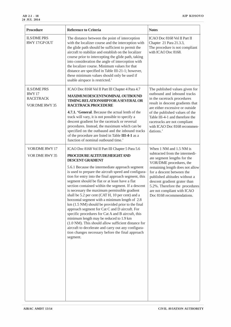
Procedure Reference to Criteria Notes
The distance between the point of interceptionwith the localizer course and the interception withthe glide path should be sufficient to permit theaircraft to stabilize and establish on the localizercourse prior to intercepting the glide path, takinginto consideration the angle of interception withthe localizer course. Minimum values for thatdistance are specified in Table III-21-1; however,these minimum values should only be used ifusable airspace is restricted.’
ICAO Doc 8168 Vol II Part IIChapter 21 Para 21.3.3,The procedure is not compliantwith ICAO Doc 8168.
ILS/DME PRSRWY 17/GP OUT
ILS/DME PRSRWY 17RACETRACK
VOR DME RWY 35
ICAO Doc 8168 Vol II Part III Chapter 4 Para 4.7
MAXIMUM DESCENTNOMINAL OUTBOUNDTIMING RELATIONSHIP FOR A SEVERAL ORRACETRACK PROCEDURE
4.7.1. ‘General. Because the actual lenth of thetrack will vary, it is not possible to specify adescent gradient for the racetrack or reversalprocedures. Instead, the maximum which can bespecified on the outbaund and the inbound tracksof the procedure are listed in Table III-4-1 as afunction of nominal outbound time.’
The published values given foroutbound and inbound tracksin the racetrack proceduresresult in descent gradients thatare either excessive or outsideof the published values of theTable III-4-1 and therefore theracetracks are not compliantwith ICAO Doc 8168 recommen-dations.’
ICAO Doc 8168 Vol II Part III Chapter 5 Para 5.6
PROCEDURE ALTITUDE/HEIGHT ANDDESCENT GRADIENT
5.6.1 Because the intermediate approach segmentis used to prepare the aircraft speed and configura-tion for entry into the final approach segment, thissegment should be flat or at least have a flatsection contained within the segment. If a descentis necessary the maximum permissible gradientshall be 5.2 per cent (CAT H, 10 per cent) and ahorzontal segment with a minimum length of 2.8km (1.5 NM) should be provided prior to the finalapproach segment for Cat C and D aircraft. Forspecific procedures for Cat A and B aircraft, thisminimum length may be reduced to 1.9 km(1.0 NM). This should allow sufficient distance foraircraft to decelerate and carry out any configura-tion changes necessary before the final approachsegment.
VOR/DME RWY 17
VOR DME RWY 35
When 1 NM and 1.5 NM issubtracted from the intermedi-ate segment lengths for theVOR/DME procedures, theremaining length does not allowfor a descent between thepublished altitudes without adescent gradient grater than5.2%. Therefore the proceduresare not compliant with ICAODoc 8168 recommendations.
24 JUL 2014
AIRAC AMDT 13/14
AIP KOSOVO AD 2.1 - 19
CIVIL AVIATION AUTHORITY
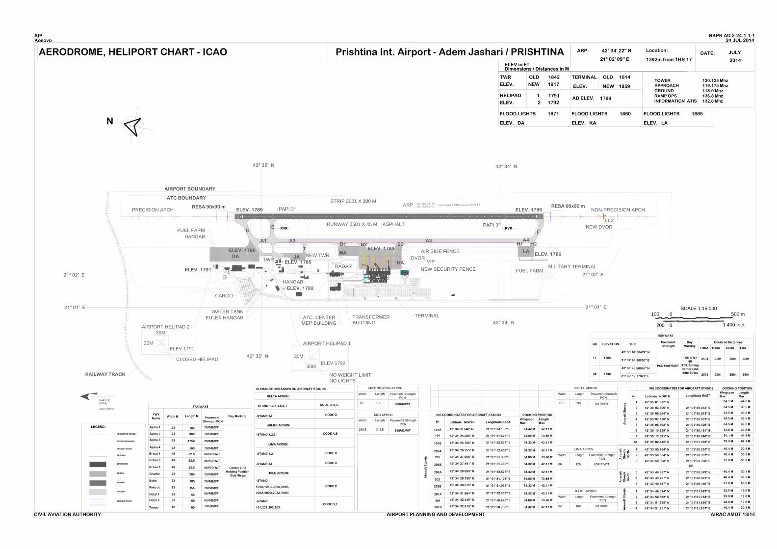
BKPR AD 2.24 CHARTS RELATED TO THE AERODROME
WARNING
INSTRUMENT FLIGHT PROCEDURES ARE PRODUCED IN
NON-INTERNATIONAL METRIC UNITS (NON-DI UNNITS)
Aerodrome, Heliport Chart - ICAO BKPR AD 2.24.1.1-1
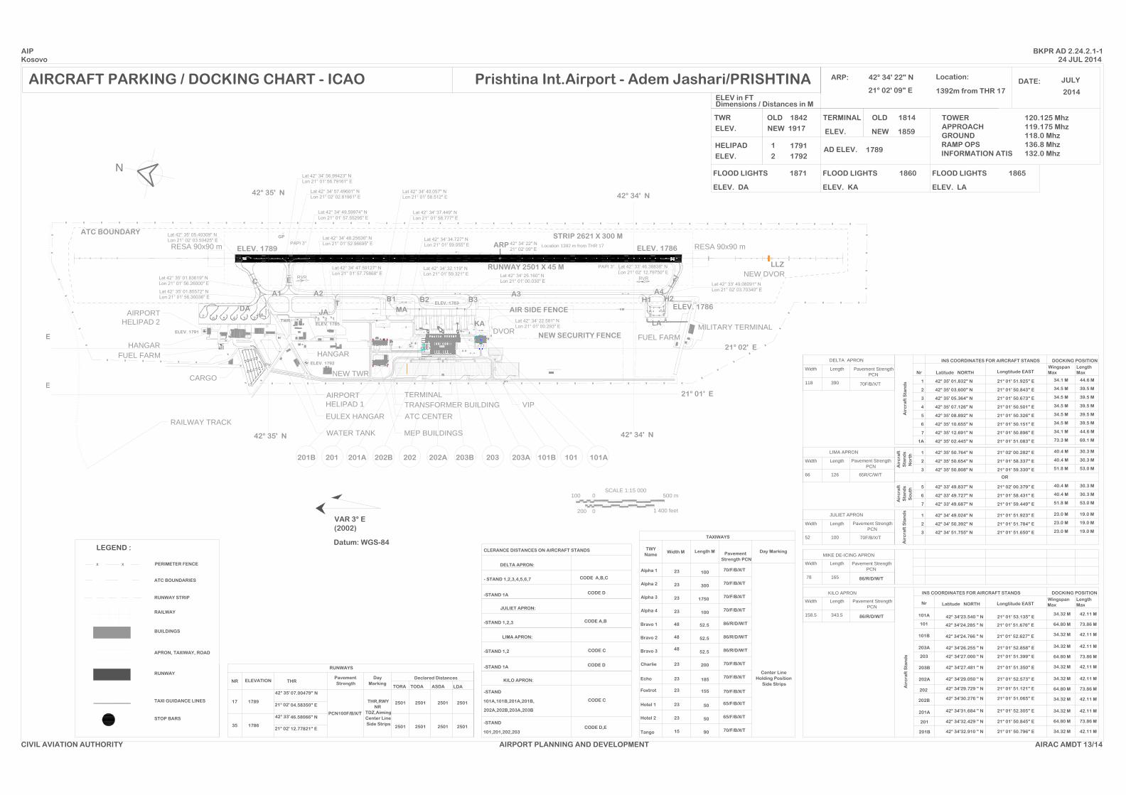
Aircraft Parking/Docking Chart - ICAO BKPR AD 2.24.2.1-1
Aerodrome Obstacle Chart - ICAO Type A BKPR AD 2.24.4.1-1
Aerodrome Obstacle Chart - ICAO Type B BKPR AD 2.24.4.2-1
Precision Approach Terrain Chart - ICAO BKPR AD 2.24.5.1-1