Bandlet-based sparsity regularization in video inpainting Ali Mosleh a , Nizar Bouguila b,⇑ , A. Ben Hamza b a Department of Electrical and Computer Engineering, Concordia University, Montréal, QC H3G 2W1, Canada b Concordia Institute for Information Systems Engineering, Concordia University, Montréal, QC H3G 2W1, Canada article info Article history: Received 6 July 2012 Accepted 13 January 2014 Available online 24 January 2014 Keywords: Bandlets Inpainting Patch fusion Regularization Video completion Spatio-temporal flows Video sequence Missing information abstract We present a bandlet-based framework for video inpainting in order to complete missing parts of a video sequence. The framework applies spatio-temporal geometric flows extracted by bandlets to reconstruct the missing data. First, a priority-based exemplar scheme enhanced by a bandlet-based patch fusion gen- erates a preliminary inpainting result. Then, the inpainting task is completed by a 3D volume regulariza- tion algorithm which takes advantage of bandlet bases in exploiting the anisotropic regularities. The method does not need extra processes in order to satisfy visual consistency. The experimental results demonstrate the effectiveness of our proposed video completion technique. Ó 2014 Elsevier Inc. All rights reserved. 1. Introduction Missing parts in still images and video sequences may be caused by damages or deliberately undesired object removal from the images or the video frames. The image/video inpainting problem has attracted a great attention in the past few years due to its pow- erful ability in fixing and restoring damaged saptial/spatio-tempo- ral data. In this paper, we focus on video inpainting as a technique to recover missing data in some specified regions of videos. Due to the large dimensionality of video data coupled with its saptio-tem- poral consistency which must be preserved, video inpainting can be considered as a challenging task even though large amount of data can be highly desirable to fill-in the missing regions. One can refer to [1] for detailed mathematical interpolation models specialized in image inpainting. The pioneering work in digital inpainting [2] employs non-linear partial differential equa- tions (PDEs) as an interpolation platform to perform image and vi- deo frame inpainting. The concepts of PDEs and interpolation in inpainting have been employed in many techniques, including [3] which derives a third-order PDE based on Taylor expansion to propagate the border isophotes to the missing regions. An explicit extension of the technique introduced in [2] is presented in [4] which applies Navier-Stoke equations. This approach applies ideas from classical fluid dynamics to continuously propagate isophote lines of the image from the exterior into the inpainting zone. As an- other technique, the proposed video inpainting scheme in [5] ben- efits from discrete p-Laplacian regularization on a weighted graph. Despite their promising results, the PDE and interpolation based methods perform frame-by-frame completion that neglects the continuity across consecutive frames unless PDEs are adapted in a 3D scheme [6]. Moreover, these methods are appropriate only for narrow and small missing regions. The concept of priority in image inpainting introduced in [7] has been adopted in various video inpainting approaches. In these techniques, a correct order of filling-in process leads to a high per- formance in the completion task. Important properties, such as availability, trackability and motion vectors of the pixels, and geo- metric properties contribute to the calculation of the priority of the missing regions to be filled-in first. For instance, the method intro- duced in [8] performs moving object segmentation to separate the background and foreground of the video. Hence, the search space is reduced for completion of partially occluded moving objects [9]. In this method a motion confidence value is used to find the priority of the filling-in area in order to maintain the temporal consistency in the foreground completion task. For the background completion step, the image inpainting technique introduced in [7] is adopted. Modifications based on analysis of continuities on stationary and non-stationary videos are carried out to find the best priority in [10]. Then, in [11] the technique is further improved for various http://dx.doi.org/10.1016/j.jvcir.2014.01.007 1047-3203/Ó 2014 Elsevier Inc. All rights reserved. ⇑ Corresponding author. Permanent address: Office EV-007-632, Concordia Institute for Information Systems Engineering, Concordia University, 1515 St. Catherine Street West, EV.007.632, H3G 2W1 Montreal, Canada. E-mail addresses: [email protected](A. Mosleh), bouguila@ciise. concordia.ca (N. Bouguila), [email protected](A.B. Hamza). J. Vis. Commun. Image R. 25 (2014) 855–863 Contents lists available at ScienceDirect J. Vis. Commun. Image R. journal homepage: www.elsevier.com/locate/jvci
Transcript
J. Vis. Commun. Image R. 25 (2014) 855–863
Contents lists available at ScienceDirect
J. Vis. Commun. Image R.
journal homepage: www.elsevier .com/ locate/ jvc i
Bandlet-based sparsity regularization in video inpainting
http://dx.doi.org/10.1016/j.jvcir.2014.01.0071047-3203/� 2014 Elsevier Inc. All rights reserved.
⇑ Corresponding author. Permanent address: Office EV-007-632, ConcordiaInstitute for Information Systems Engineering, Concordia University, 1515 St.Catherine Street West, EV.007.632, H3G 2W1 Montreal, Canada.
a Department of Electrical and Computer Engineering, Concordia University, Montréal, QC H3G 2W1, Canadab Concordia Institute for Information Systems Engineering, Concordia University, Montréal, QC H3G 2W1, Canada
a r t i c l e i n f o
Article history:Received 6 July 2012Accepted 13 January 2014Available online 24 January 2014
Keywords:BandletsInpaintingPatch fusionRegularizationVideo completionSpatio-temporal flowsVideo sequenceMissing information
a b s t r a c t
We present a bandlet-based framework for video inpainting in order to complete missing parts of a videosequence. The framework applies spatio-temporal geometric flows extracted by bandlets to reconstructthe missing data. First, a priority-based exemplar scheme enhanced by a bandlet-based patch fusion gen-erates a preliminary inpainting result. Then, the inpainting task is completed by a 3D volume regulariza-tion algorithm which takes advantage of bandlet bases in exploiting the anisotropic regularities. Themethod does not need extra processes in order to satisfy visual consistency. The experimental resultsdemonstrate the effectiveness of our proposed video completion technique.
� 2014 Elsevier Inc. All rights reserved.
1. Introduction
Missing parts in still images and video sequences may be causedby damages or deliberately undesired object removal from theimages or the video frames. The image/video inpainting problemhas attracted a great attention in the past few years due to its pow-erful ability in fixing and restoring damaged saptial/spatio-tempo-ral data. In this paper, we focus on video inpainting as a techniqueto recover missing data in some specified regions of videos. Due tothe large dimensionality of video data coupled with its saptio-tem-poral consistency which must be preserved, video inpainting can beconsidered as a challenging task even though large amount of datacan be highly desirable to fill-in the missing regions.
One can refer to [1] for detailed mathematical interpolationmodels specialized in image inpainting. The pioneering work indigital inpainting [2] employs non-linear partial differential equa-tions (PDEs) as an interpolation platform to perform image and vi-deo frame inpainting. The concepts of PDEs and interpolation ininpainting have been employed in many techniques, including[3] which derives a third-order PDE based on Taylor expansion topropagate the border isophotes to the missing regions. An explicitextension of the technique introduced in [2] is presented in [4]
which applies Navier-Stoke equations. This approach applies ideasfrom classical fluid dynamics to continuously propagate isophotelines of the image from the exterior into the inpainting zone. As an-other technique, the proposed video inpainting scheme in [5] ben-efits from discrete p-Laplacian regularization on a weighted graph.Despite their promising results, the PDE and interpolation basedmethods perform frame-by-frame completion that neglects thecontinuity across consecutive frames unless PDEs are adapted ina 3D scheme [6]. Moreover, these methods are appropriate onlyfor narrow and small missing regions.
The concept of priority in image inpainting introduced in [7] hasbeen adopted in various video inpainting approaches. In thesetechniques, a correct order of filling-in process leads to a high per-formance in the completion task. Important properties, such asavailability, trackability and motion vectors of the pixels, and geo-metric properties contribute to the calculation of the priority of themissing regions to be filled-in first. For instance, the method intro-duced in [8] performs moving object segmentation to separate thebackground and foreground of the video. Hence, the search space isreduced for completion of partially occluded moving objects [9]. Inthis method a motion confidence value is used to find the priorityof the filling-in area in order to maintain the temporal consistencyin the foreground completion task. For the background completionstep, the image inpainting technique introduced in [7] is adopted.Modifications based on analysis of continuities on stationary andnon-stationary videos are carried out to find the best priority in[10]. Then, in [11] the technique is further improved for various
856 A. Mosleh et al. / J. Vis. Commun. Image R. 25 (2014) 855–863
camera motions by keeping the track of similar regions. The prior-ity is determined based on the trackability of the pixels in themethod introduced in [12]. The highest priority fragment aroundthe boundary of the missing region is completed using a graph-cut fragment updating instead of copying just a similar texturefrom the undamaged region. In [13] a priority-based method con-siders the video completion task as a global search optimization inorder to find the best match. The whole video is considered as avolume and a multi-scale scheme is employed to reduce the com-putation time. Motion layer segmentation is the key step in themethod proposed in [14]. Each separate layer is completed usingthe image inpainting method, and then all the layers are combinedin order to restore the final video. A two phase sampling and align-ment video inpainting technique is introduced in [15]. The methodpredicts motion data in the foreground, then missing moving fore-ground pixels are reconstructed by spatio-temporal alignment ofthe sampled data. Then, the background inpainting is done by 3Dtensor voting as an extension of the still image repairing techniqueintroduced in [16]. The methods in [17,18] proposed to inpaint vid-eos by transferring sampled motion fields from the available partsof the video. The latter method tracks patches containing missingregions in the adjacent frames by employing a global motionestimation scheme. In [19,20] 3D patch-based probability modelswith potential applications in video inpainting are introduced.The probability model introduced in [19] is an alternative for mo-tion models such as optical-flow. A sparsity-based prior for a var-iational Bayesian model is defined for video sequences. Thedamaged portion of a video can be treated in this Bayesian frame-work as an inpainting task. A learning strategy in [20] on the vi-deo’s 3D space–time patches leads to video epitomes. Epitomesare viewed as a set of 3D arrays of probability distributions appliedfor video reconstruction. Although the preliminary results of videoinpainting using these methods are promising, they need moreimprovements to be able to deal with large missing portions.
Maintaining the visual consistency along with handling thelarge dimensionality of videos in the inpainting process is animportant fact. No wonder we see complicated steps in the state-of-the-art techniques, such as segmentation of different motionlayers or objects, foreground/background separation, tracking,optical-flow mosaics computation and so onto cope with spatio-temporal consistency. In this paper we propose an approach thattakes advantage of the bandlets sparse representation to recon-struct missing data visually pleasingly. Image sparse representa-tion methods were introduced for spatial inpainting problems[21–23]. In such methods, missing pixels are inferred by adaptivelyupdating the sparse representation (e.g. wavelets, DCT, etc).Although these approaches are very challenging to be adapted tovideo completion that deals with unsound and damaged estimatedmotion vectors, they yield satisfactory results in the case of imageinpainting. Apparently, employing an efficient sparse representa-tion can enhance the inpainting results. The main motivationbehind employing the bandlet domain is due to its effective capa-bility in capturing the geometric properties of an image as an effi-cient sparse representation [24]. The captured geometric featuresare used in our technique to firstly blend the results of patchmatching in order to keep the visual consistency. Secondly, theoverall bandlet geometry of the frames can be a good prior if weconsider the video inpainting as an ill-posed linear problem. Theobtained overall geometry is used for sparse regularization toreconstruct the video. In our method, making distinction betweenstatic camera videos and sequences containing camera motions isnot needed. Besides, there is no segmentation, tracking or complexmotion estimation as applied in many of the previously discussedmethods to facilitate the inpainting process. This is the main differ-ence with our previous work [25] that relies on an accurate back-ground/foreground segmentation in order to treat videos captured
by static and moving cameras in different fashions by patch match-ing rather than bandlet-based patch fusion and 3D regularization.
The rest of this paper is organized as follows. Section 2 describesthe idea behind the bandlet transform capability in reconstructingmissing regions. Then, the proposed bandlet-based video inpaintingmethod is presented in Section 3. In Section 4, the experimental re-sults are provided. Finally, Section 5 concludes this paper.
2. Using bandlets in inpainting
The bandlet framework can achieve an effective geometric rep-resentation of texture images. It is essential in sparse regulariza-tion and spatial or spatio-temporal data reconstruction for digitalinpainting purposes.
Although geometric regularity along image edges is an aniso-tropic regularity, conventional wavelet bases can only exploit theisotropic regularity on square domains. An image can be differen-tiable in the direction of the tangent of an edge curve even thoughthe image may be discontinuous across the curve. Bandlet trans-form [26] exploits such anisotropic regularity. Bandlet bases con-struct orthogonal vectors elongated in the direction of themaximum regularity of a function. The earlier bandlet bases[27,28] have been improved by a multi-scale geometry definedover wavelet coefficients [29,30]. Indeed, bandlets are anisotropicwavelets warped along the geometric flow.
Considering the Alpert transform as a polynomial wavelet trans-form adapted to an irregular sampling grid, one can obtain vectorsthat have vanishing moments on this irregular sampling grid. Thisis the principal need to approximate warped wavelet coefficients.Only a few vectors of Alpert basis can efficiently approximate a vec-tor corresponding to a function with anisotropic regularity. Thisbandletization using wavelet coefficients is defined as
bkj;l;nðxÞ ¼
Xp
al;n½p�wkj;pðxÞ; ð1Þ
where j and k represent wavelet scale and orientation, respectively.The al;n½p� are the coefficients of the Alpert transform where l is thescale and n is the index of the Alpert vector. In essence, al;n½p� are the
coordinates of the bandlet function bkj;l;n. These coefficients strictly
depend on the local geometric flow. Bandlet coefficient are gener-
ated by inner products f ; bkj;l;n
D Eof the image f with the bandlet
functions bkj;l;n. The set of wavelet coefficients are segmented in
squares S for polynomial flow approximation of the geometry. For
each scale 2j and orientation k, the segmentation is carried outusing a recursive subdivision in dyadic squares. A square S shouldbe further subdivided into four sub-squares, if there is still a geo-metric directional regularity in the square. Apparently, only forthe edge squares, the adaptive flow is needed to be computed to ob-tain the bandlet bases. The geometry of an image evolves through
scales. Therefore, for each scale 2j of the orientation k a different
geometry Ckj is chosen. The set of all geometries fCk
j g representsthe overall geometry of an image. Each member of this set is in facta geometry value associated to one segmentation square S. For de-tails about bandlets the reader is referred to [26].
The image inpainting problem may be formulated as follows. Animage I contains a set of missing pixels indicated by X and a source(U ¼ I nX) area. The goal is finding an image �I such that�IðxÞ is equalto IðxÞ for the pixels that belong to U, i.e., �IðxÞ ¼ IðxÞ 8x R X whilethe overall geometry of �I has the same geometrical regularity asthat of I in U. In the presence of additive noise x we have the imagef with missing pixels as f ¼ hI þx where
hIðxÞ ¼0 if x 2 X
IðxÞ if x 2 U:
�ð2Þ
A. Mosleh et al. / J. Vis. Commun. Image R. 25 (2014) 855–863 857
A sparsity-based regularization solution for the inverse problemf ¼ hI þx was proposed in [31] as
�I ¼ arg ming12kf � hgk2 þ k
Xk
jhg;wkij: ð3Þ
This minimization has been used with the orthogonal wavelet baseswk for denoising [31] where the value of k is chosen based on thelevel of noise and can be set to 1 for a noise-free image. Consideringthe bandlets as anisotropic wavelets warped along the geometryflow, we substitute the conventional wavelet bases of Eq. (3) withthe bandlet bases introduced in Eq. (1) as
�I ¼ arg ming12kf � hgk2 þ k
Xj;l;n;k
g; bCk;j;l;n
D E��� ���: ð4Þ
where similar to Eq. (1), k and j are the number of orientations andscales of the wavelets, and l; n are the sampling grid parameters inthe Alpert transform employed in the bandlet transform. As discussedin the next section, our video inpainting scheme is subject to recon-structing the missing part of the frames generated due to occlusionsand/or undesired object removal. Therefore, we avoid the noise levelin the above equations (i.e., x ¼ 0) and rewrite Eq. (4) as
�I ¼ arg ming
Xj;l;n;k
g; bCk;j;l;n
D E��� ���: ð5Þ
This equation is indeed minimizing the ‘1 norm of the bandlet im-age representation by which we achieve a solution for the spatialinpainting problem. In the next section, we utilize this idea to de-velop a 3D video volume regularization algorithm as well as theeffectiveness of bandlets for blending the matching results of a bestmatch search approach in the video completion task.
3. Spatio-temporal video completion
An important task of video completion is to fill in large missingregions produced by object occlusion or undesired object removal.The large missing region completion cannot be carried out well bysimply applying PDE, regularization, or other interpolation basedmethods. On the other hand, in the exemplar-based methods, find-ing a reliable area around the missing parts and also finding aproper match in the source frames toward the end of the processreduces the accuracy of the results. Therefore, a video inpaintingtechnique is proposed here that benefits from both an exemplar-based patch matching and a sparsity regularization scheme. Theprocess starts looking for best candidates that match a patch Wp
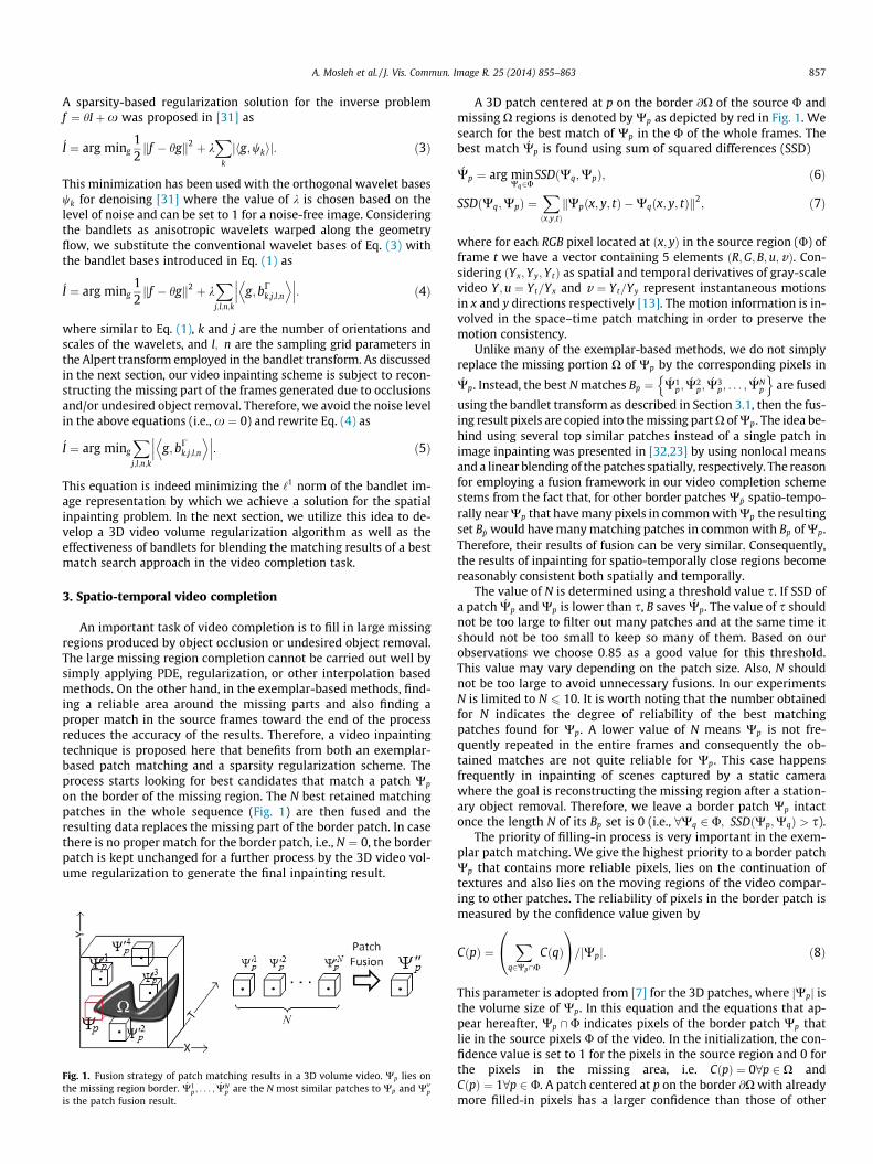
on the border of the missing region. The N best retained matchingpatches in the whole sequence (Fig. 1) are then fused and theresulting data replaces the missing part of the border patch. In casethere is no proper match for the border patch, i.e., N ¼ 0, the borderpatch is kept unchanged for a further process by the 3D video vol-ume regularization to generate the final inpainting result.
Fig. 1. Fusion strategy of patch matching results in a 3D volume video. Wp lies onthe missing region border. �W1
p ; . . . ; �WNp are the N most similar patches to Wp and W00p
is the patch fusion result.
A 3D patch centered at p on the border @X of the source U andmissing X regions is denoted by Wp as depicted by red in Fig. 1. Wesearch for the best match of Wp in the U of the whole frames. Thebest match �Wp is found using sum of squared differences (SSD)
�Wp ¼ arg minWq2U
SSDðWq;WpÞ; ð6Þ
SSDðWq;WpÞ ¼Xðx;y;tÞkWpðx; y; tÞ �Wqðx; y; tÞk2
; ð7Þ
where for each RGB pixel located at ðx; yÞ in the source region (U) offrame t we have a vector containing 5 elements ðR;G;B; u;vÞ. Con-sidering ðYx;Yy;YtÞ as spatial and temporal derivatives of gray-scalevideo Y ;u ¼ Yt=Yx and v ¼ Yt=Yy represent instantaneous motionsin x and y directions respectively [13]. The motion information is in-volved in the space–time patch matching in order to preserve themotion consistency.
Unlike many of the exemplar-based methods, we do not simplyreplace the missing portion X of Wp by the corresponding pixels in�Wp. Instead, the best N matches Bp ¼ �W1
p;�W2
p;�W3
p; . . . ; �WNp
n oare fused
using the bandlet transform as described in Section 3.1, then the fus-ing result pixels are copied into the missing part X of Wp. The idea be-hind using several top similar patches instead of a single patch inimage inpainting was presented in [32,23] by using nonlocal meansand a linear blending of the patches spatially, respectively. The reasonfor employing a fusion framework in our video completion schemestems from the fact that, for other border patches W�p spatio-tempo-rally near Wp that have many pixels in common with Wp the resultingset B�p would have many matching patches in common with Bp of Wp.Therefore, their results of fusion can be very similar. Consequently,the results of inpainting for spatio-temporally close regions becomereasonably consistent both spatially and temporally.
The value of N is determined using a threshold value s. If SSD ofa patch �Wp and Wp is lower than s, B saves �Wp. The value of s shouldnot be too large to filter out many patches and at the same time itshould not be too small to keep so many of them. Based on ourobservations we choose 0:85 as a good value for this threshold.This value may vary depending on the patch size. Also, N shouldnot be too large to avoid unnecessary fusions. In our experimentsN is limited to N 6 10. It is worth noting that the number obtainedfor N indicates the degree of reliability of the best matchingpatches found for Wp. A lower value of N means Wp is not fre-quently repeated in the entire frames and consequently the ob-tained matches are not quite reliable for Wp. This case happensfrequently in inpainting of scenes captured by a static camerawhere the goal is reconstructing the missing region after a station-ary object removal. Therefore, we leave a border patch Wp intactonce the length N of its Bp set is 0 (i.e., 8Wq 2 U; SSDðWp;WqÞ > s).
The priority of filling-in process is very important in the exem-plar patch matching. We give the highest priority to a border patchWp that contains more reliable pixels, lies on the continuation oftextures and also lies on the moving regions of the video compar-ing to other patches. The reliability of pixels in the border patch ismeasured by the confidence value given by
CðpÞ ¼X
q2Wp\UCðqÞ
0@
1A=jWpj: ð8Þ
This parameter is adopted from [7] for the 3D patches, where jWpj isthe volume size of Wp. In this equation and the equations that ap-pear hereafter, Wp \U indicates pixels of the border patch Wp thatlie in the source pixels U of the video. In the initialization, the con-fidence value is set to 1 for the pixels in the source region and 0 forthe pixels in the missing area, i.e. CðpÞ ¼ 08p 2 X andCðpÞ ¼ 18p 2 U. A patch centered at p on the border @X with alreadymore filled-in pixels has a larger confidence than those of other
Fig. 3. Fusion result for 3 different source images of Barbara. (a)–(c) Source images.(d) Resulting fused image.
858 A. Mosleh et al. / J. Vis. Commun. Image R. 25 (2014) 855–863
patches. The number of edge pixels can be used to measure thestructural information contained in the patch. This is obtained bymeans of the already computed spatial derivatives Yx and Yy. Sup-pose �Yx and �Yy represent 0-1 maps of thresholded horizontal andvertical derivatives of the entire frames, respectively. Instead ofmanually defining threshold values to generate these two binarymaps, Otsu’s method can be used to find a proper threshold. Then,the structural data value of Wp is defined as
DðpÞ ¼X
q2Wp\U
�YxðqÞ _ �YyðqÞ
0@
1A=jWpj: ð9Þ
Similarly, �Yt that contains 0-1 maps of temporal derivatives is usedto determine the motion data value of a border patch,
MðpÞ ¼X
q2Wp\U
�YtðqÞ
0@
1A=jWpj: ð10Þ
A high value of D means that the patch is placed on the continuationof a highly textured region. Also, a large value of M indicates a largenumber of moving pixels with large motion vectors in the borderpatch. The priority of a border patch is obtained as follows
PðpÞ ¼ CðpÞ � DðpÞ �MðpÞ: ð11Þ
A border patch Wp with the highest PðpÞ is chosen from the wholeframes to be filled-in first. Once the patch matching is carried out,the confidence value is updated as �CðpÞ ¼ aCðpÞ where 0 < a < 1.The derivative matrices �Yx; �Yy and �Yt are also updated by copyingthe derivative values of �Wp into the corresponding locations inWp \X. Then the process is repeated for a new highest priority bor-der patch until there is no border patch unprocessed.
The resulting video sequence containing unfixed regions (i.e.those with unreliable matches) are passed to the sparsity regulariza-tion inpainting stage for further processes as discussed in Section 3.2.
3.1. Patch fusion
Multi-scale decomposition (MSD) based image fusion schemes,especially wavelet-based ones, have a great performance com-pared to regular methods [33]. However, as discussed in Section 2,due to its capability to capture more complicated geometric flowsand structural information in images, the bandlet transform ismuch more appropriate than wavelet transform for analysis andsynthesis of edges and textures [34]. Hence, we design a fusionscheme based on bandlets to blend the best patch search results.
Fig. 2 shows the proposed image fusion scheme. Consider I1 toIM as M images of a single scene captured from M different sources(e.g., cameras, sensors, etc.), the bandlet transform is applied oneach Ii to obtain the geometric features Ci in the form of real num-bers and bandlet coefficients C of each image. Now we need to gen-erate a fused set of geometry flows and bandlet coefficients.
The fused geometry flow set CF is computed as follows
CF ¼XM
i¼1
jiCi
!, XM
i¼1
ji
!; ð12Þ
Fig. 2. Bandlet-based fusion framework for M source images.
where ji is 0 if mean li of the values of Ci is lower than a thresholdr. The value of r is chosen as the mean of all l1;l2; . . . ;lM . Indeed,this thresholding leads to applying only the highly structurally sim-ilar source images to produce the fused geometry. The most similarC of the source images are selected and their mean value generatesCF . The fused bandlet coefficients’ set is calculated as
CF ¼XM
i¼1
Ci
!=M: ð13Þ
It is worth mentioning that the bandlet coefficients C and the geo-metric features C are produced for l; n; j; k scales and orientationsof Eq. (1).
The inverse bandlet transform is performed on CF and CF in or-der to generate the fused image from the M source images. Fig. 3(d)shows an example of the bandlet based fusion result for 3 sourceimages, where Barbara’s image is manually blurred and the result-ing images are considered as the source images depicted inFig. 3(a)–(c).
Now consider the set Bp of the N best matching patches ob-tained for Wp in the proposed video inpainting technique in Sec-tion 3. Each �Wi
p of Bp has a size of X � Y � T. The correspondingspatial planes of patches in Bp are fused using the aforementionedfusion method to produce the resulting inpainting patch W00p, i.e.,
where WpðtiÞ represents all the X � Y pixels at time indextið1 6 ti 6 TÞ in the patch Wp. This fusion scheme takes more struc-tural information into account than simply copying the source (U)pixels of the best match �W1
p to produce the final inpainting result.Besides, as mentioned earlier such patch fusion strategy followedthe introduced search process, helps gain more visual consistency.
3.2. Spatio-temporal regularization using bandlets
Algorithm 1. Bandlet-based 3D video volume inpainting
1: i ¼ 0 and Vi¼0 ¼ y
2: while jV ðiþ1Þ � V ðiÞj > e3: Find �Vi using Eq. (16)4: for z ¼ 1! X � Y � T do [Update the estimate;
Viþ1 ¼ TBð�ViÞ]5: Bandlet transform on �Vi
z
6: Soft-thresholding Eq. (17) on �Viz bandlet coefficients
7: Generate Viþ1z by inverse bandlet transform
8: end for9: i iþ 110: end while
un. Image R. 25 (2014) 855–863 859
As a result of the N best patch matching strategy, the unreliableborder patches (i.e. those that less likely have a match in the whole
Fig. 4. A damaged video volume from different views. (a) X–Y planes view. (b) T–Yplanes view.
Fig. 5. Various iteration results of Algorithm 1 on the 11th frame of the video ofFig. 4. For a better illustration the images are cropped from left, right and bottom.
Fig. 6. The 2-stage proposed video completion method shown for a sample frame.(a) Original frame. (b) Stage 1 result: Exemplar-based patch fusion step (Sec-tion 3.1). (c) Stage 2 result: bandlet-based regularization on the result of stage 1(Section 3.2).
sequence or those less frequently are repeated in the frames) arerecognized by the inpainting system. These kinds of patches re-main unchanged in the first inpainting stage and are passed tothe 3D regularization procedure introduced in the followingparagraphs.
Considering the 2D minimization problem introduced in Eq. (5)as an exhaustive optimization, we adopt the soft-theresholdingalgorithm which has been used as a solution for multi-scale wave-let representation inverse problems such as denoising [35].
The overall geometry is supposed to be fixed for an estimate ofthe original video. The soft-theresholding function is carried outiteratively for the minimization of Eq. (5) for each plane in the3D volume video. At each iteration, the estimate video Viþ1 isupdated as follows
Viþ1 ¼ TBð�ViÞ; ð15Þ
�Vi ¼ ViðxÞ if x 2 X
yðxÞ if x 2 U:
(ð16Þ
Pixels of the original video volume are represented by yðxÞ in theabove equation. TB denotes the soft-thresholding function per-formed in the bandlet domain for each existing plane in �Vi definedas
TBðfzÞ ¼Xj;l;n;k
tkðhfz; bj;l;n;kiÞ:bj;l;n;k; ð17Þ
where fz denotes each existing plane in the video volume. For a 3Dvolume consisting of T frames of X � Y pixels, we consider T planesalong the time, X planes along horizontal and Y planes along verticaldirections. tkðxÞ ¼max 0;1� k
jxj
� �x and the value of k goes to 0 as
the iteration number increases. bj;l;n;k represents the bandlet func-tions of various scales and orientations as in Eq. (1).
Algorithm 1 presents the details of the minimization procedureto inpaint a video volume. This algorithm stops once the differencebetween two consecutive estimates is less than a small value e.One may think of applying this algorithm on each frame indepen-dently as the inpainting task. Obviously, in a video sequence theflow of motions and trajectories is very important and needs tobe considered in the inpainting task to preserve the consistency.Fig. 4(a) displays the resulting video of the exemplar-based repairstage done on the original video of Fig. 7(c). This video containsblack holes representing unfixed patches. Rotating the video vol-ume around the Y axis, one can see the video volume T–Y planes.As seen for example in the T–Y plane of X ¼ 145 in Fig. 4(b), pixelsof the missing region do not only lie on the spatial geometric flowsbut also those along the time direction. As a consequence, in eachiteration of Algorithm 1, the regularization is carried out on planesX–Y ; T–X and T–Y denoted by �Vi
z. Due to limitations of a 3D illus-tration, the inpainting result for only a single frame is shown inFig. 5.
A. Mosleh et al. / J. Vis. Comm
4. Experimental results
Several video sequences, including some that are provided in[11,9] are used to evaluate the proposed video inpainting method.1
This set of videos contains sequences captured by both static andmoving camera. The resolution of each video sequence is320� 240. The intermediate results of the proposed two-stage videocompletion technique performed on a sample video sequence for one
1 For sample video inpainting results visit: http://users.encs.concordia.ca/mos_ali/VideoInpainting/JVCIR.htm.
of its frames are presented in Fig. 6. In the implementation, the fol-lowing settings are used:
� The size of each patch is 9� 9� 5 in the patch matchingprocess.� a is set to 0.5 for confidence update.� s is set to 0.85 to choose the N top matching patches.� Gray-scale values of the RGB frames are found by ðRþ Gþ BÞ=3
whenever needed like instantaneous motion calculation.� Considering a border patch Wp centered at p ¼ ðx; y; tÞ, the
search range is reduced to x� 50 < x < xþ 50; y� 50< y < yþ 50 and t � 7 < t < t þ 7 in the video sequence inorder to avoid unnecessary search. This does not negatively
Fig. 7. Completion results for different video sequences. In each sub-figure, the toprow shows the original frames and the bottom row demonstrates the correspondinginpainting results.
860 A. Mosleh et al. / J. Vis. Commun. Image R. 25 (2014) 855–863
affect the patch matching result, since most likely the bestpatches for an arbitrary patch exist in its adjacent space andtime locations.
The details of the bandlet transform applied in our techniqueare as follows:
� Number of scales j, on which geometry is computed, is set to 3.� The introduced scale factor l by Alpert transform in the bandlet-
ization (Section 2) is set to 4.� Orthogonal wavelets are used in the bandetization.� In the wavelet transform, Daubechies wavelets are employed.� A fixed size 8� 8 segmentation is employed instead of the com-
plex dyadic segmentation introduced in Section 2.
Fig. 7 depicts the results of our video inpainting scheme on dif-ferent sequences. These videos are selected from TV, video games,and also captured by a digital camera. The objective in the se-quence of Fig. 7(a) is to remove the stationary object and fill-inits missing region with proper data. Since the camera and theremoved object are static, as discussed in Section 3, there is notmuch information about what was behind the object in the wholesequence. Therefore, the inpainting result is mostly produced by3D regularization rather than patch matching. Other examplesillustrated in Fig. 7 depict inpainting results of videos containingcamera motions. In all cases, the proposed method performs thecompletion task quite well. In order to gain insight into the effectof each step of the proposed video completion scheme, severalanalyses are next presented as well as a comparison with twostate-of-the-art methods.
4.1. Effects of patch fusion and 3D regularization
As mentioned before, the N best patch sorting and fusion resultsin a better performance in comparison to conventional patchreplacement. We show this by means of a quantitative comparison.
A manual damage is generated on an original video sequence.Then, the damaged video is completed by the spatio-temporal vi-deo completion approach presented in Section 3. The completionis performed once without patch fusion, i.e, replacing the missingparts of a border patch by the corresponding pixels of the bestmatching patch. The spatio-temporal completion is carried-outonce again by applying the introduced patch fusion technique.However, since the second stage of our proposed method (i.e., 3Dregularization) is not applied in this experiment, we simply avoidthe threshold s (used to find N) and set N ¼ 5. Then, for both cases,the difference of the completion result of the damaged video andthe original video sequence is observed by computing the MSE va-lue for the corresponding frames of the original and the completionresult video sequences. Fig. 8(a) shows a frame of the video chosenfor evaluation which is damaged as in Fig. 8(b) and then completedas in Fig. 8(c) and (d).
The plot indicated as ‘‘Exemplar Bandlet-Based Patch Fusion’’ inFig. 9 shows mean square error (MSE) graph of all the 50 frames ofthe original video and the spatio-temporal completion result se-quence using the bandlet based patch fusion. Obviously, the MSEvalue of the fusion-based completion for almost all the frames islower than that of the conventional exemplar-based completionscheme labeled as ‘‘Exemplar-based’’ in Fig. 9. In order to showthe performance of the proposed bandlet-based patch fusion tech-nique in video completion tasks, the experiment is performed an-other time using another image fusion technique. A patch fusionscheme similar to Section 3.1 is considered for a well-known imagefusion technique based on wavelets introduced in [36]. Then, thecompletion task is performed by means of the exemplar-basedplatform applying this fusion technique. Similar to the wavelet
stage of the bandlet transform, Daubechies wavelets are employedin this wavelet-based patch fusion scheme. The resulting MSE val-ues of all the generated frames using this method are presented asthe ‘‘Exemplar-based Wavelet patch Fusion’’ plot in Fig. 9. The plotsshown in Fig. 9 indicate visually pleasing completion results for thebandlet-based patch fusion scenario compared to simply replacing
Fig. 8. (a) Original frame. (b) Damaged frame. (c) Regular exemplar-based inpainting result (Frame number 13, MSE = 19.13). (d) Patch fusion exemplar-based inpaintingresult (Frame number 13, MSE = 18.4). (e) Two-stage (exemplar patch fusion-based method followed by the bandlet-based 3D regularization) inpainting result (Framenumber 13, MSE = 11.86).
5 10 15 20 25 30 35 40 45 500
5
10
15
20
25
30
35
Frame Number
MSE
Exemplar−based (no fusion)Exemplar Wavelet−based Patch FusionExemplar Bandlet−based Patch Fusion
Exemplar Bandlet−basedPatch Fusion + 3D Regularization
Fig. 9. Objective evaluation of patch fusion and 3D regularization in videoinpainting.
Fig. 10. (a) Original frame. (b) Damaged frame. (c) Proposed method completionresult (Frame number 22, MSE = 8.18).
Fig. 11. Objective evaluation of the proposed video completion method. Averageframe MSE is 6.11, 6.02, 5.1863 for Patwardhan et al. [9], Tang et al. [18], and theproposed two-stage method, respectively.
A. Mosleh et al. / J. Vis. Commun. Image R. 25 (2014) 855–863 861
the missing region by the best matching patch and also using aneffective fusion method [36] based on wavelets.
Similar experiments are carried out in order to evaluate theeffectiveness of bandlet-based 3D regularization in the inpaintingtask. This time, the proposed two-stage video inpainting methodis carried-out for the video sequence of Fig. 8. In other words, thedamaged video of Fig. 8(b) has been inpainted using spatio-tempo-ral patch-fusion followed by the 3D regularization step in order torefine the results and also to preserve the visual consistency(Fig. 8(e)). The corresponding MSE plots in Fig. 9 show a higherperformance for the proposed video completion method comparedto using solely the patch fusion scheme or the convectional exem-plar-based video inpainting technique presented in Section 3. It isworth mentioning again that the regularization methods are notpractical for large regions due to the blur effect they impose onthe resulting frames [7]. However, as presented here a precisecombination of a regularization-based method and an exemplar-based method can result in a higher accuracy. The majority ofthe run-time of our algorithm is spent on bandlet transform whichlacks an optimized implementation since it is relatively new.Therefore, it is not straightforward to discuss the complexity in a
precise way that can be presented in this paper. With the presetimplementation the run-time may be around 3 h to finish a com-pletion task for a typical video employed in our experiments. Therun-time improvement is a challenge to be addressed in a futurework.
4.2. Comparison with state-of-the-art methods
The performance of video inapinting/completion methods isgenerally evaluated subjectively. However, we use MSE to evaluate
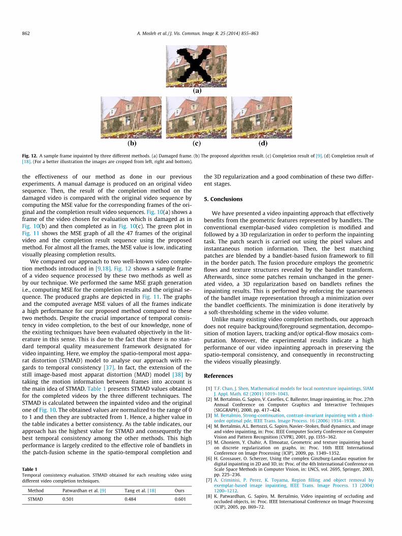
Fig. 12. A sample frame inpainted by three different methods. (a) Damaged frame. (b) The proposed algorithm result. (c) Completion result of [9]. (d) Completion result of[18]. (For a better illustration the images are cropped from left, right and bottom).
862 A. Mosleh et al. / J. Vis. Commun. Image R. 25 (2014) 855–863
the effectiveness of our method as done in our previousexperiments. A manual damage is produced on an original videosequence. Then, the result of the completion method on thedamaged video is compared with the original video sequence bycomputing the MSE value for the corresponding frames of the ori-ginal and the completion result video sequences. Fig. 10(a) shows aframe of the video chosen for evaluation which is damaged as inFig. 10(b) and then completed as in Fig. 10(c). The green plot inFig. 11 shows the MSE graph of all the 47 frames of the originalvideo and the completion result sequence using the proposedmethod. For almost all the frames, the MSE value is low, indicatingvisually pleasing completion results.
We compared our approach to two well-known video comple-tion methods introduced in [9,18]. Fig. 12 shows a sample frameof a video sequence processed by these two methods as well asby our technique. We performed the same MSE graph generationi.e., computing MSE for the completion results and the original se-quence. The produced graphs are depicted in Fig. 11. The graphsand the computed average MSE values of all the frames indicatea high performance for our proposed method compared to thesetwo methods. Despite the crucial importance of temporal consis-tency in video completion, to the best of our knowledge, none ofthe existing techniques have been evaluated objectively in the lit-erature in this sense. This is due to the fact that there is no stan-dard temporal quality measurement framework designated forvideo inpainting. Here, we employ the spatio-temporal most appa-rat distortion (STMAD) model to analyse our approach with re-gards to temporal consistency [37]. In fact, the extension of thestill image-based most apparat distortion (MAD) model [38] bytaking the motion information between frames into account isthe main idea of STMAD. Table 1 presents STMAD values obtainedfor the completed videos by the three different techniques. TheSTMAD is calculated between the inpainted video and the originalone of Fig. 10. The obtained values are normalized to the range of 0to 1 and then they are subtracted from 1. Hence, a higher value inthe table indicates a better consistency. As the table indicates, ourapproach has the highest value for STMAD and consequently thebest temporal consistency among the other methods. This highperformance is largely credited to the effective role of bandlets inthe patch-fusion scheme in the spatio-temporal completion and
Table 1Temporal consistency evaluation. STMAD obtained for each resulting video usingdifferent video completion techniques.
Method Patwardhan et al. [9] Tang et al. [18] Ours
STMAD 0.501 0.484 0.601
the 3D regularization and a good combination of these two differ-ent stages.
5. Conclusions
We have presented a video inpainting approach that effectivelybenefits from the geometric features represented by bandlets. Theconventional exemplar-based video completion is modified andfollowed by a 3D regularization in order to perform the inpaintingtask. The patch search is carried out using the pixel values andinstantaneous motion information. Then, the best matchingpatches are blended by a bandlet-based fusion framework to fillin the border patch. The fusion procedure employs the geometricflows and texture structures revealed by the bandlet transform.Afterwards, since some patches remain unchanged in the gener-ated video, a 3D regularization based on bandlets refines theinpainting results. This is performed by enforcing the sparsenessof the bandlet image representation through a minimization overthe bandlet coefficients. The minimization is done iteratively bya soft-thresholding scheme in the video volume.
Unlike many existing video completion methods, our approachdoes not require background/foreground segmentation, decompo-sition of motion layers, tracking and/or optical-flow mosaics com-putation. Moreover, the experimental results indicate a highperformance of our video inpainting approach in preserving thespatio-temporal consistency, and consequently in reconstructingthe videos visually pleasingly.
References
[1] T.F. Chan, J. Shen, Mathematical models for local nontexture inpaintings, SIAMJ. Appl. Math. 62 (2001) 1019–1043.
[2] M. Bertalmio, G. Sapiro, V. Caselles, C. Ballester, Image inpainting, in: Proc. 27thAnnual Conference on Computer Graphics and Interactive Techniques(SIGGRAPH), 2000, pp. 417–424.
[3] M. Bertalmio, Strong-continuation, contrast-invariant inpainting with a third-order optimal pde, IEEE Trans. Image Process. 16 (2006) 1934–1938.
[4] M. Bertalmio, A.L. Bertozzi, G. Sapiro, Navier–Stokes, fluid dynamics, and imageand video inpainting, in: Proc. IEEE Computer Society Conference on ComputerVision and Pattern Recognition (CVPR), 2001, pp. I355–362.
[5] M. Ghoniem, Y. Chahir, A. Elmoataz, Geometric and texture inpainting basedon discrete regularization on graphs, in: Proc. 16th IEEE InternationalConference on Image Processing (ICIP), 2009, pp. 1349–1352.
[6] H. Grossauer, O. Scherzer, Using the complex Ginzburg-Landau equation fordigital inpainting in 2D and 3D, in: Proc. of the 4th International Conference onScale Space Methods in Computer Vision, in: LNCS, vol. 2695, Springer, 2003,pp. 225–236.
[7] A. Criminisi, P. Perez, K. Toyama, Region filling and object removal byexemplar-based image inpainting, IEEE Trans. Image Process. 13 (2004)1200–1212.
[8] K. Patwardhan, G. Sapiro, M. Bertalmio, Video inpainting of occluding andoccluded objects, in: Proc. IEEE International Conference on Image Processing(ICIP), 2005, pp. II69–72.
A. Mosleh et al. / J. Vis. Commun. Image R. 25 (2014) 855–863 863
[9] K.A. Patwardhan, G. Sapiro, M. Bertalmio, Video inpainting under constrainedcamera motion, IEEE Trans. Image Process. 16 (2007) 4545–4553.
[10] T.K. Shih, N.C. Tang, W.-S. Yeh, T.-J. Chen, W. Lee, Video inpainting and implantvia diversified temporal continuations, in: Proc. 14th annual ACMInternational Conference on Multimedia, 2006, pp. 133–136.
[11] T.K. Shih, N.C. Tang, J.-N. Hwang, Exemplar-based video inpainting withoutghost shadow artifacts by maintaining temporal continuity, IEEE Trans.Circuits Syst. Video Technol. 19 (2009) 347–360.
[12] Y.-T. Jia, S.-M. Hu, R.R. Martin, Video completion using tracking and fragmentmerging, Visual Comput. 21 (2005) 601–610.
[13] Y. Wexler, E. Shechtman, M. Irani, Space-time completion of video, IEEE Trans.Pattern Anal. Mach. Intell. 29 (2007) 463–476.
[14] Y. Zhang, J. Xiao, M. Shah, Motion layer based object removal in videos, in:Proc. Seventh IEEE Workshops on Application of Computer Vision (WACV/MOTIONS’05), 2005, pp. 516–521.
[15] J. Jia, Y.-W. Tai, T.-P. Wu, C. Tang, Video repairing under variable illuminationusing cyclic motions, IEEE Trans. Pattern Anal. Mach. Intell. 28 (2006) 832–839.
[16] J. Jia, C.-K. Tang, Image repairing: robust image synthesis by adaptive nd tensorvoting, in: Proc. of IEEE Computer Society Conference on Computer Vision andPattern Recognition (CVPR), 2003, pp. 643–650.
[17] T. Shiratori, Y. Matsushita, X. Tang, S.B. Kang, Video completion by motion fieldtransfer, in: Proc. of IEEE Computer Society Conference on Computer Visionand Pattern Recognition (CVPR), 2006, pp. 411–418.
[18] N. Tang, C.-T. Hsu, C.-W. Su, T. Shih, H.-Y. Liao, Video inpainting on digitizedvintage films via maintaining spatiotemporal continuity, IEEE Trans.Multimedia 13 (2011) 602–614.
[19] X. Li, Y. Zheng, Patch-based video processing: a variational bayesian approach,IEEE Trans. Circuits Syst. Video Technol. 19 (2009) 27–40.
[20] V. Cheung, B.J. Frey, N. Jojic, Video epitomes, in: Proc. of IEEE Computer SocietyConference on Computer Vision and Pattern Recognition (CVPR), 2005, pp. 42–49.
[21] O. Guleryuz, Nonlinear approximation based image recovery using adaptivesparse reconstructions and iterated denoising-part i: theory, IEEE Trans. ImageProcess. 15 (3) (2006) 539–554.
[22] O.G. Guleryuz, Nonlinear approximation based image recovery using adaptivesparse reconstructions and iterated denoising-part ii: adaptive algorithms,IEEE Trans. Image Process. 15 (3) (2006) 555–571.
[23] Z. Xu, J. Sun, Image inpainting by patch propagation using patch sparsity, IEEETrans. Image Process. 19 (5) (2010) 1153–1165.
[24] A. Mosleh, N. Bouguila, A.B. Hamza, A video completion method based onbandlet transform, in: Proc. IEEE International Conference on Multimedia andExpo (ICME), Barcelona, Spain, 2011, pp. 1–6.
[25] A. Mosleh, N. Bouguila, A. Ben Hamza, Video completion using bandlettransform, IEEE Trans. Multimedia 14 (6) (2012) 1591–1601.
[26] S. Mallat, G. Peyre, A review of bandlet methods for geometrical imagerepresentation, Numer. Algorithms 44 (2007) 205–234.
[27] E.L. Pennec, S. Mallat, Sparse geometric image representations with bandelets,IEEE Trans. Image Process. 14 (2005) 423–438.
[28] E.L. Pennec, S. Mallat, Bandelet image approximation and compression, SIAMMultiscale Model. Simul. 4 (2005) 992–1039.
[29] S. Mallat, G. Peyre, Surface compression with geometric bandelets, ACM Trans.Graphics 24 (2005) 601–608.
[30] S. Mallat, G. Peyre, Orthogonal bandlets bases for geometric imageapproximation, Commun. Pure Appl. Math. 61 (2008) 1173–1212.
[32] A. Wong, J. Orchard, A nonlocal-means approach to exemplar-basedinpainting, in: Proc. IEEE International Conference on Image Processing(ICIP), 2008, pp. 2600–2603.
[33] Z. Zhang, R. Blum, A categorization of multiscale-decomposition-based imagefusion schemes with a performance study for a digital camera application,Proc. IEEE 87 (8) (1999) 1315–1326.
[34] X.Q.J. Yan, G. Xie, Z. Zhu, B. Chen, A novel image fusion algorithm based onbandelet transform, Chin. Opt. Lett. 5 (2007) 569–572.
[35] J. Starck, M. Elad, D. Donoho, Redundant multiscale transforms and theirapplication for morphological component separation, Adv. Imaging ElectronPhys. 132 (2004) 287–348.
[36] G. Pajares, J.M. de la Cruz, A wavelet-based image fusion tutorial, PatternRecognit. 37 (9) (2004) 1855–1872.
[37] P. Vu, C. Vu, D. Chandler, A spatiotemporal most-apparent-distortion model forvideo quality assessment, in: Proc. IEEE International Conference on ImageProcessing (ICIP), 2011, pp. 2505–2508.
[38] E.C. Larson, D.M. Chandler, Most apparent distortion: full-reference imagequality assessment and the role of strategy, J. Electron. Imaging 19 (1) (2010)011006-1–011006–21.


![Scalable Spectral k-Support Norm Regularization for Robust ...ymc/papers/conference/cikm16_pu… · 2;1 norm [29]. is a constant parameter used to balance low rankness and sparsity.](https://static.documents.pub/doc/80x56/60d4e4cc901aa418633dee04/scalable-spectral-k-support-norm-regularization-for-robust-ymcpapersconferencecikm16pu.jpg)