48
Bandwidth-based load-balancing with failover. The easy way. We need more bandwidth.
Bandwidth-based load-balancing with failover. The easy way.
We need more bandwidth.

Presenter information
Tomas Kirnak
Network design
Security, wireless
Servers, Virtualization
Mikrotik Certified Trainer
Atris, Slovakia
Established 1991
Complete IT solutions
Networking, servers
Virtualization
IP security systems
Load-balancing, why?
• Distributing workload to multiple network links to maximize throughput and minimize latency.
• Using multiple network links, when properly configured, will also provide redundancy.
Load balancing types
• Bonding
• Policy routing
• PCC
• Bandwidth based
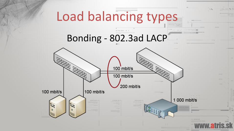
Load balancing types
Bonding - 802.3ad LACP
Bonding
+ Easy to implement
Automatic redundancy with fail-over
- You need to control of both ends of the link
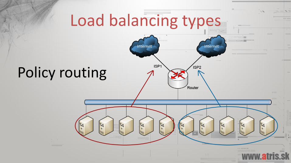
Load balancing types
Policy routing
Policy routing
+ Easy to implement
You have exact control of traffic
- Not dynamic
Scalability problems
Load balancing types
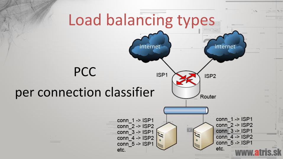
PCC
per connection classifier
PCC
+ Easy to configure
Good scalability
- Not aware of link state (bandwidth wise)
Not so great with very un-similiar links (4:1)

Load balancing types
For presentations on these load-balancing methods, please see
www.tiktube.com – PL 2010 and PL 2012
Load balancing types
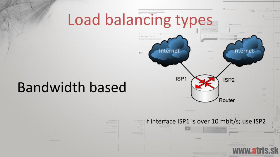
Bandwidth based
If interface ISP1 is over 10 mbit/s; use ISP2
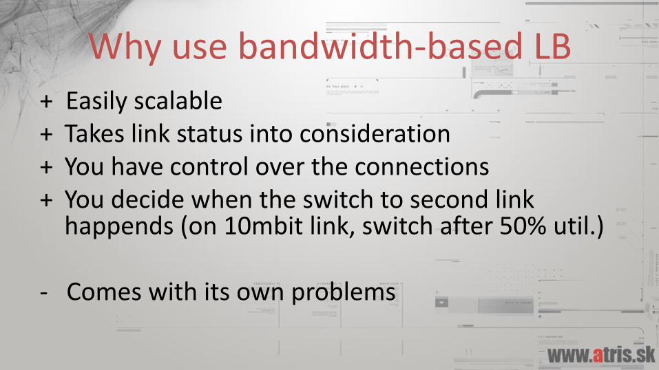
Why use bandwidth-based LB+ Easily scalable+ Takes link status into consideration+ You have control over the connections+ You decide when the switch to second link
happends (on 10mbit link, switch after 50% util.)
- Comes with its own problems

Implementation considerations• There are multiple ways to do bandwidth based
load balancing, neither is so easy.
• MPLS TE• Mangle + bit of scripting <-- this presentation
www.tiktube.com – PL 2010 and PL 2012

Underlying technologies
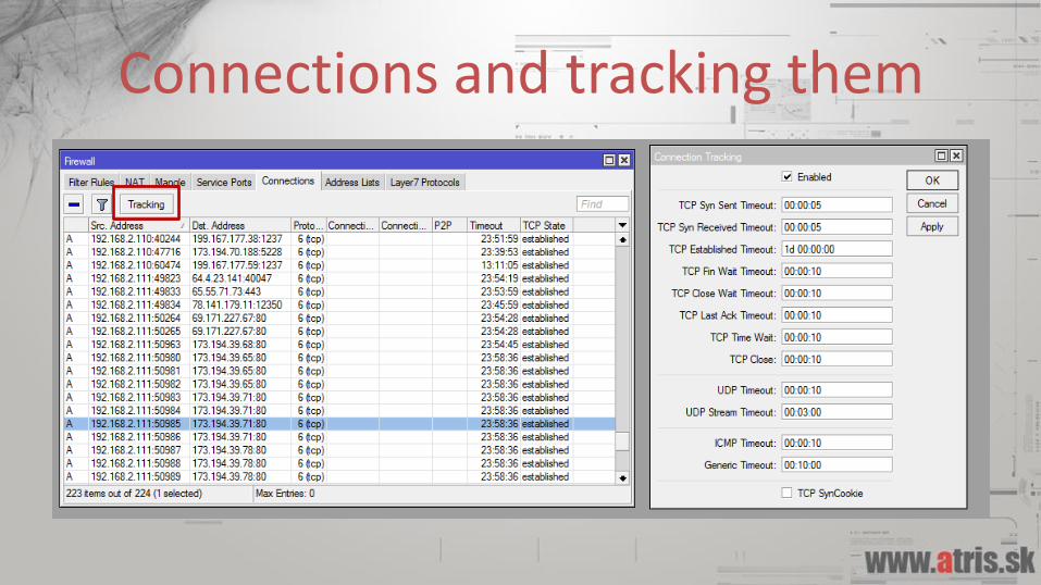
Connections and tracking them
What is a connection
• We can define a connection as a packet flow with the same pair of source and destination IP addresses and ports.
• In case of UDP, this is would be an UDP stream.
• 192.168.2.10:49481 <-> 8.8.8.8:53
Mangle
• Mangle is a facility in ROS which allows us to “mark” packets or connections, and later use that mark for our purposes.
• Mangle marks do NOT leave the router.
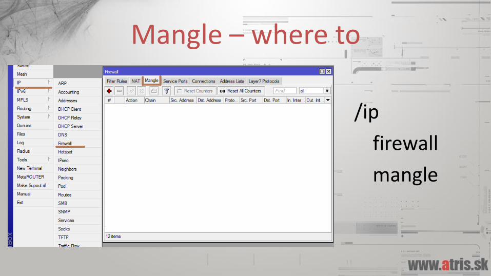
Mangle – where to
/ip
firewall
mangle
Routing tables
• A routing table tells the router which next hop to forward packets to, depending on the packets destination IP.
• 0.0.0.0/0 -> 77.21.34.12
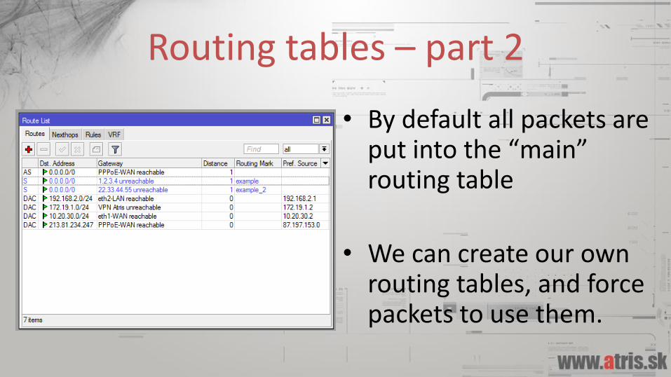
Routing tables – part 2
• By default all packets are put into the “main” routing table
• We can create our own routing tables, and force packets to use them.
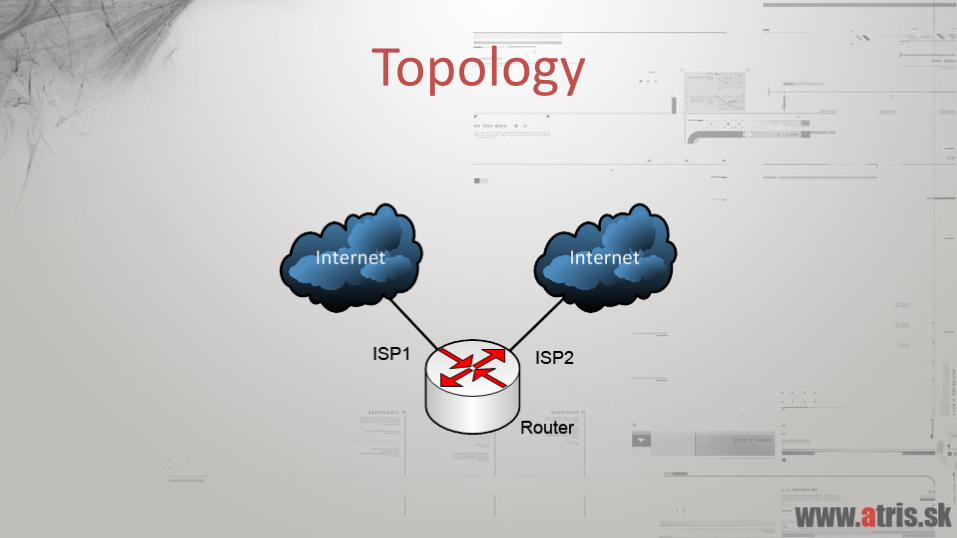
Topology
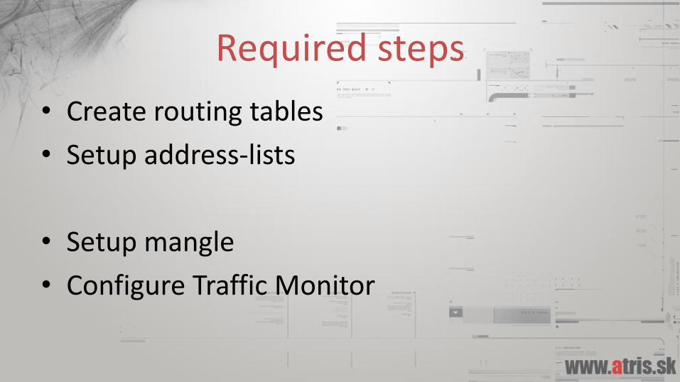
Required steps
• Create routing tables
• Setup address-lists
• Setup mangle
• Configure Traffic Monitor
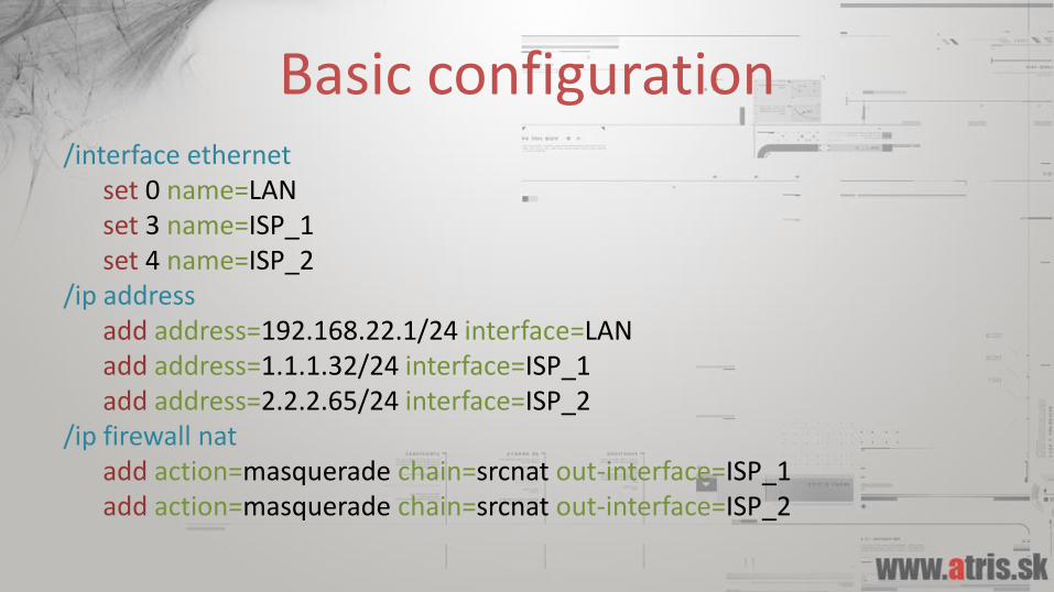
Basic configuration/interface ethernet
set 0 name=LANset 3 name=ISP_1set 4 name=ISP_2
/ip addressadd address=192.168.22.1/24 interface=LANadd address=1.1.1.32/24 interface=ISP_1add address=2.2.2.65/24 interface=ISP_2
/ip firewall natadd action=masquerade chain=srcnat out-interface=ISP_1add action=masquerade chain=srcnat out-interface=ISP_2
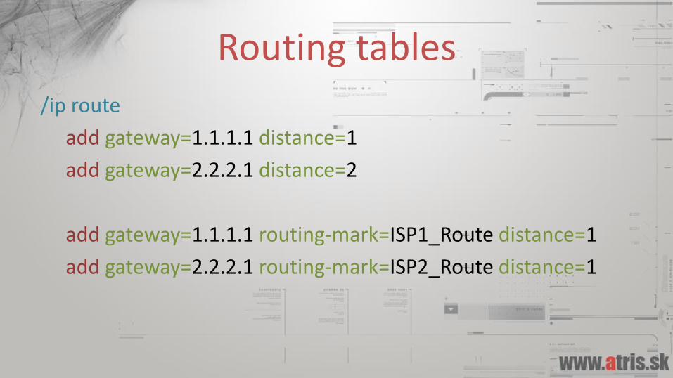
Routing tables
/ip route
add gateway=1.1.1.1 distance=1
add gateway=2.2.2.1 distance=2
add gateway=1.1.1.1 routing-mark=ISP1_Route distance=1
add gateway=2.2.2.1 routing-mark=ISP2_Route distance=1
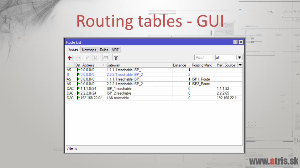
Routing tables - GUI
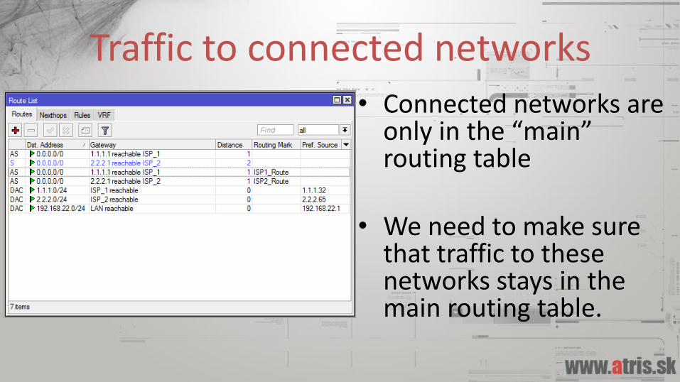
Traffic to connected networks• Connected networks are
only in the “main” routing table
• We need to make sure that traffic to these networks stays in the main routing table.
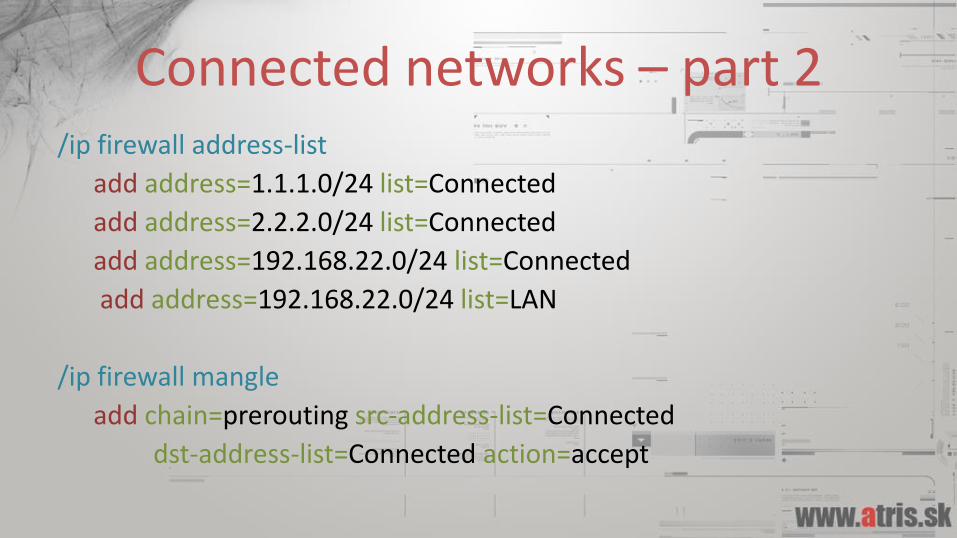
Connected networks – part 2/ip firewall address-list
add address=1.1.1.0/24 list=Connected
add address=2.2.2.0/24 list=Connected
add address=192.168.22.0/24 list=Connected
add address=192.168.22.0/24 list=LAN
/ip firewall mangle
add chain=prerouting src-address-list=Connected
dst-address-list=Connected action=accept
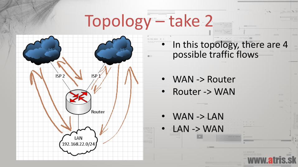
Topology – take 2• In this topology, there are 4
possible traffic flows
• WAN -> Router• Router -> WAN
• WAN -> LAN• LAN -> WAN
Taking care of incoming connections
• When a connection is initiated from the internet through one of the ISPs we need to ensure that this connections is replied through the same ISP (from the same public IP)
• We need to mark these connections, and then put them in the proper routing table.
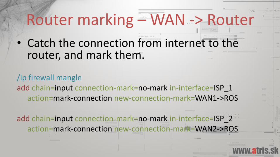
Router marking – WAN -> Router
• Catch the connection from internet to the router, and mark them.
/ip firewall mangleadd chain=input connection-mark=no-mark in-interface=ISP_1
action=mark-connection new-connection-mark=WAN1->ROS
add chain=input connection-mark=no-mark in-interface=ISP_2action=mark-connection new-connection-mark=WAN2->ROS
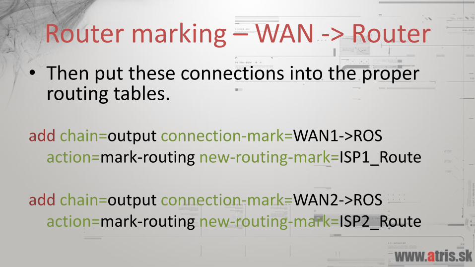
Router marking – WAN -> Router
• Then put these connections into the proper routing tables.
add chain=output connection-mark=WAN1->ROSaction=mark-routing new-routing-mark=ISP1_Route
add chain=output connection-mark=WAN2->ROSaction=mark-routing new-routing-mark=ISP2_Route
Taking care of the LAN
• Same principle applies to the LAN.
• Connections initiated from the internet through one ISP, should be replied to through the same ISP.
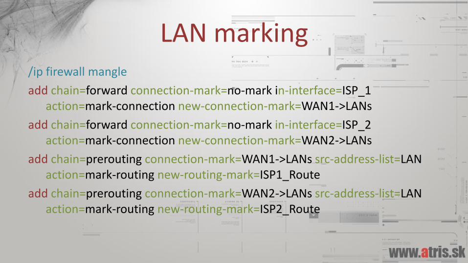
LAN marking/ip firewall mangle
add chain=forward connection-mark=no-mark in-interface=ISP_1action=mark-connection new-connection-mark=WAN1->LANs
add chain=forward connection-mark=no-mark in-interface=ISP_2action=mark-connection new-connection-mark=WAN2->LANs
add chain=prerouting connection-mark=WAN1->LANs src-address-list=LAN action=mark-routing new-routing-mark=ISP1_Route
add chain=prerouting connection-mark=WAN2->LANs src-address-list=LAN action=mark-routing new-routing-mark=ISP2_Route
Incoming connections - done
• We have ensured that when a connection from the internet to our router, or services inside of our network is established, it works.
LAN – partially done
• Connections from the internet to our LAN will now work through both ISPs
• So what about connections outgoing from our LAN to the internet?
• These we actually want to load-balance.
A sticky connection• A sticky connection is a connection, that once
established through one interface, will always go out that exact interface.
• This is required, because when we switch to a second link, we only need to switch new connections.
• In PCC, this is done automatically. Using our approach however, this has to be done manually.
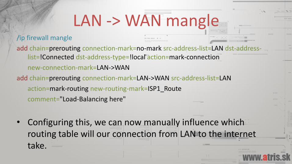
LAN -> WAN mangle/ip firewall mangle
add chain=prerouting connection-mark=no-mark src-address-list=LAN dst-address-list=!Connected dst-address-type=!local action=mark-connection
new-connection-mark=LAN->WAN
add chain=prerouting connection-mark=LAN->WAN src-address-list=LAN
action=mark-routing new-routing-mark=ISP1_Route
comment="Load-Balancing here"
• Configuring this, we can now manually influence which routing table will our connection from LAN to the internet take.
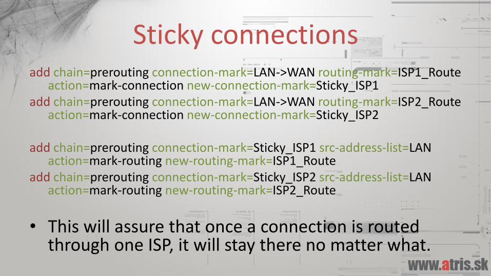
Sticky connectionsadd chain=prerouting connection-mark=LAN->WAN routing-mark=ISP1_Route
action=mark-connection new-connection-mark=Sticky_ISP1add chain=prerouting connection-mark=LAN->WAN routing-mark=ISP2_Route
action=mark-connection new-connection-mark=Sticky_ISP2
add chain=prerouting connection-mark=Sticky_ISP1 src-address-list=LAN action=mark-routing new-routing-mark=ISP1_Route
add chain=prerouting connection-mark=Sticky_ISP2 src-address-list=LAN action=mark-routing new-routing-mark=ISP2_Route
• This will assure that once a connection is routed through one ISP, it will stay there no matter what.
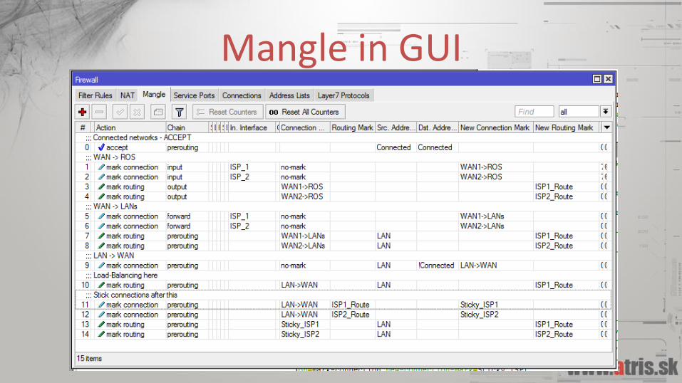
Mangle in GUI
What’s the final result?
• We can load balancing manually
• Connections go out ISP1, then we can switch the mangle rule to ISP2, but connections already using ISP1 will stay there.
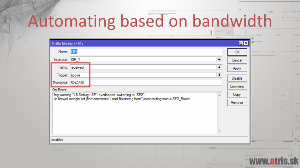
Automating based on bandwidth
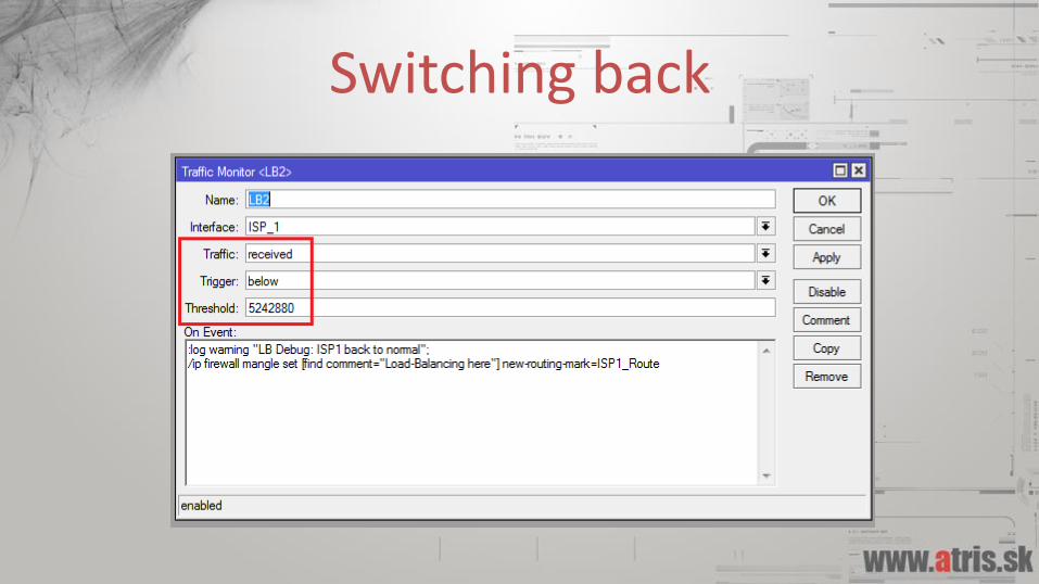
Switching back
Final result
• Connections routed through ISP1, until its link is at 5mbit/s.
• After this limit all new connections will go through ISP2 until the ISP1 link is under its limit.
• Automated, bandwidth-based load balancing.
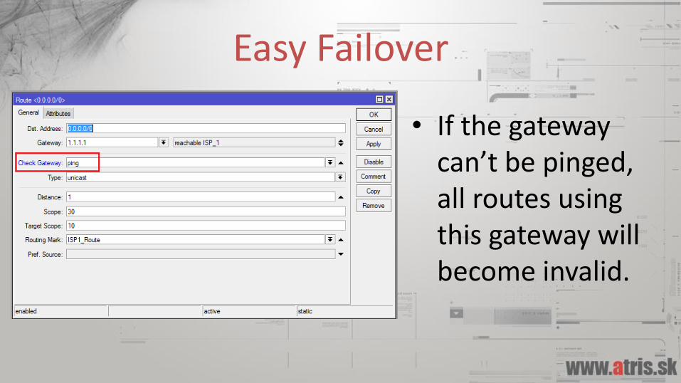
Easy Failover
• If the gateway can’t be pinged, all routes using this gateway will become invalid.

A different approach
• This approach will not work if the link failure happens after the gateway.
• Recursive route lookup, netwatch etc.
• http://wiki.mikrotik.com/wiki/Failover_Scripting

Find me after the presentation for any questions.