MONTREAL PROTOCOL ON SUBSTANCES THAT DEPLETE THE OZONE LAYER UNEP Technology and Economic Assessment Panel TASK FORCE DECISION XX/8 REPORT “ASSESSMENT OF ALTERNATIVES TO HCFCS AND HFCS AND UPDATE OF THE TEAP 2005 SUPPLEMENT REPORT DATA”
Transcript
MONTREAL PROTOCOL
ON SUBSTANCES THAT DEPLETE
THE OZONE LAYER
UNEPTechnology and Economic Assessment Panel
TASK FORCE DECISION XX/8 REPORT
“ASSESSMENT OF ALTERNATIVES TO HCFCS AND HFCS AND UPDATE OF THE TEAP 2005 SUPPLEMENT REPORT DATA”
May 2009
TASK FORCE DECISION XX/8 REPORT
“ASSESSMENT OF ALTERNATIVES TO HCFCS AND HFCS AND UPDATE OF THE TEAP 2005 SUPPLEMENT REPORT DATA”
May 2009
May 2009 TEAP XX/8 Task Force Report iii
Montreal ProtocolOn Substances that Deplete the Ozone Layer
Report of theUNEP Technology and Economic Assessment Panel
May 2009
TASK FORCE DECISION XX/8 REPORT
“ASSESSMENT OF ALTERNATIVES TO HCFCS AND HFCS AND UPDATE OF THE TEAP 2005 SUPPLEMENT REPORT DATA”
The text of this report is composed in Times New Roman.
Co-ordination: Lambert Kuijpers and Dan Verdonik
Composition: Lambert Kuijpers
Layout: Lambert Kuijpers and Ozone Secretariat
Reproduction: UNON Nairobi
Date: May 2009
Under certain conditions, printed copies of this report are available from:
UNITED NATIONS ENVIRONMENT PROGRAMMEOzone Secretariat, P.O. Box 30552, Nairobi, Kenya
This document is available in portable document format fromhttp://www.ozone.unep.org/
No copyright involved. This publication may be freely copied, abstracted and cited, with acknowledgement of the source of the material.
Printed in Nairobi, Kenya, 2009.
May 2009 TEAP XX/8 Task Force Reportiv
TASK FORCE DECISION XX/8 REPORT
“ASSESSMENT OF ALTERNATIVES TO HCFCS AND HFCS AND UPDATE OF THE TEAP 2005 SUPPLEMENT REPORT DATA”
May 2009
May 2009 TEAP XX/8 Task Force Report v
DISCLAIMER
The United Nations Environment Programme (UNEP), the Technology and Economic Assessment Panel (TEAP) co-chairs and members, the Technical Options Committees chairs, co-chairs and members, the TEAP Task Forces co-chairs and members, and the companies and organisations that employ them do not endorse the performance, worker safety, or environmental acceptability of any of the technical and economic options discussed.
UNEP, the TEAP co-chairs and members, the Technical Options Committees chairs, co-chairs and members, and the Technology and Economic Assessment Panel Task Forces co-chairs and members, in furnishing or distributing the information that follows, do not make any warranty or representation, either express or implied, with respect to the accuracy, completeness, or utility; nor do they assume any liability of any kind whatsoever resulting from the use or reliance upon any information, material, or procedure contained herein.
ACKNOWLEDGEMENTS
The UNEP Technology and Economic Assessment Panel and the XX/8 Task Force co-chairs and members wish to express thanks to all who contributed from governments, both Article 5 and non-Article 5, to the Ozone Secretariat, as well as to many individuals involved in Protocol issues, without whose involvement this XX/8 report including the updated data to the supplementary report would not have been possible.
The opinions expressed are those of the Panel and its Task Force and do not necessarily reflect the reviews of any sponsoring or supporting organisation.
May 2009 TEAP XX/8 Task Force Reportvi
Table of ContentsTABLE OF CONTENTS....................................................................................................................VII
2.1 THE PROCESS............................................................................................................................ 132.2 INFORMATION IN THE ANNEXES; BANKS AND EMISSIONS DATA...............................................16
3.2.1 New Equipment Options...................................................................................................173.2.2 Service of Existing Equipment.........................................................................................183.2.3 Not-In-Kind Alternative Technologies..............................................................................183.2.4 Product Energy Efficiency Improvement Technologies.....................................................183.2.5 Refrigerant Annual Demand............................................................................................19
4.1 REFRIGERANTS IN USE IN COMMERCIAL REFRIGERATION.............................................................214.2 REFRIGERANT OPTIONS FOR NEW SYSTEMS................................................................................21
6 UNITARY AIR CONDITIONING..............................................................................................29
6.1 DESCRIPTION OF PRODUCT CATEGORY.......................................................................................296.2 CURRENT SITUATION.................................................................................................................29
6.2.1 Primary HCFC-22 Replacements.....................................................................................296.2.2 Developed Country Status................................................................................................306.2.3 Developing Country Status..............................................................................................30
7 CHILLER AIR CONDITIONING..............................................................................................33
7.1 DESCRIPTION OF PRODUCT CATEGORY.......................................................................................337.2 TYPES OF CHILLERS................................................................................................................... 337.3 CURRENT SITUATION.................................................................................................................34
7.3.1 Primary HCFC-22 Replacements in New Chillers............................................................347.3.2 Centrifugal Chillers......................................................................................................... 357.3.3 Primary HCFC-22 Replacements in Existing Positive Displacement Chillers..................36
8 VEHICLE AIR CONDITIONING..............................................................................................39
8.1 INTRODUCTION.......................................................................................................................... 398.1.1 Regulations affecting Vehicle Air Conditioning and Refrigerants.....................................39
8.2 OPTIONS FOR FUTURE MOBILE AIR CONDITIONING SYSTEMS.................................................418.2.1 Bus and Rail Air Conditioning.........................................................................................418.2.2 Passenger Car and Light Truck Air Conditioning............................................................42
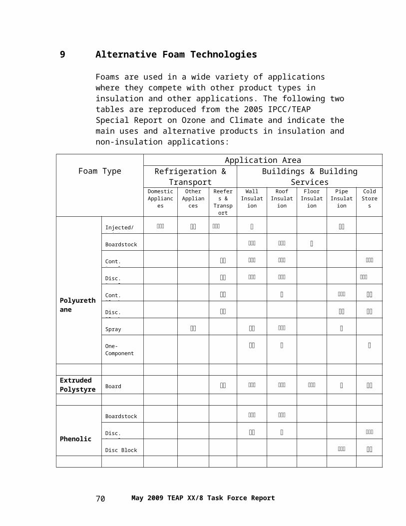
9 ALTERNATIVE FOAM TECHNOLOGIES.............................................................................47
FOAMS AND OTHER PRODUCTS FOR INSULATION APPLICATIONS...........................................................48FOAMS AND OTHER PRODUCTS FOR NON-INSULATION APPLICATIONS...................................................489.1 POLYURETHANE FOAMS............................................................................................................. 49
9.1.1 Current Status.................................................................................................................. 499.1.2 Established HFC and HCFC alternatives.........................................................................51
9.1.4 Energy Efficiency and Climate Considerations................................................................559.2 POLYSTYRENE (XPS).................................................................................................................57
9.2.1 Current Status.................................................................................................................. 589.2.2 Existing HCFC and HFC Alternatives.............................................................................589.2.3 Emerging HCFC and HFC Alternatives...........................................................................59
10 FIRE PROTECTION.................................................................................................................. 61
10.1 CURRENT STATUS OF ALTERNATIVES.....................................................................................6110.2 CURRENT BANKS AND EMISSIONS..........................................................................................6310.3 NEW TECHNOLOGICAL DEVELOPMENTS.................................................................................6610.4 TRENDS FOR THE FUTURE......................................................................................................67
11.1 DESCRIPTION OF PRODUCT CATEGORY..................................................................................6911.2 CURRENT SITUATION.............................................................................................................6911.3 POTENTIAL HCFC AND HFC REPLACEMENTS........................................................................7011.4 CONSUMPTION AND EMISSIONS..............................................................................................72
12 INHALED THERAPY FOR ASTHMA AND COPD.................................................................73
ANNEX 2 ON FLUOROCARBON NOMENCLATURE....................................................................90
May 2009 TEAP XX/8 Task Force Reportviii
ANNEX 3 UPDATE OF THE DATA FROM THE 2005 TEAP SUPPLEMENT REPORT; FIRE PROTECTION..................................................................................................................................... 92
ANNEX 4 UPDATE OF THE DATA FROM THE 2005 TEAP SUPPLEMENT REPORT; FOAMS............................................................................................................................................................... 98
ANNEX 5 UPDATE OF THE DATA FROM THE 2005 TEAP SUPPLEMENT REPORT; REFRIGERATION AND AIR CONDITIONING.............................................................................102
A5.1 REFRIGERATION AND AIR CONDITIONING.............................................................................102A5.1.1 BAU-World: Banks and Emissions.............................................................................102A5.1.2 BAU-Non-Article 5 Countries; Banks and Emissions.................................................109A5.1.3 BAU-Article 5 Countries; Banks and Emissions.........................................................112A5.1.4 MIT-World; Banks and Emissions..............................................................................116A5.1.5 MIT-Non-Article 5 Countries; Banks and Emissions..................................................119A5.1.6 MIT-Article 5 Countries; Banks and Emissions..........................................................123
ANNEX 6 SUMMARY OF BANKS AND EMISSIONS DATA......................................................127
A6.1 BANKS AND EMISSIONS IN TONNES......................................................................................127A6.2 BANKS AND EMISSIONS IN TONNES CO2 EQUIVALENT..........................................................128
May 2009 TEAP XX/8 Task Force Report ix
1 Executive Summary
This report responds to the request by Parties in Decision XX/8, paragraph 1. It describes the alternatives to HCFCs and HFCs as well as current market penetration for all relevant sectors and sub-sectors, including refrigeration and air conditioning, foams, fire protection, solvents and inhaled therapy. It presents updated data (compared to 2005) on ODS and HFC banks and emissions for fire protection, foams, and refrigeration and air conditioning.
Approximately 100 million domestic refrigerators and freezers are produced annually. An estimated 1500 to 1800 million units are now installed globally. Conversion of all new production domestic refrigerators and freezers from ozone-depleting refrigerants is complete; non-Article 5 countries completed conversions by 1996, Article 5 countries by 2008. 63 percent of current new production employs HFC-134a refrigerant and 35.5 percent employ hydrocarbon refrigerants, either HC-600a or blends of HC-600a and HC-290. Two industry dynamics of interest are second-generation migration from HFC-134a to HC-600a and preliminary discussions on using unsaturated HFCs (sometimes referred to as HFOs)1 to displace HFC-134a usage. Each of these dynamics is motivated by global warming considerations.
Conversions from HFC-134a to HC-600a began several years ago in Japan. This has progressed to include the majority of new refrigerator production in Japan. A major U.S. manufacturer recently announced its intent to introduce refrigerators using HC-600a refrigerant. Codes and standards modifications and approvals are currently in process and commercial introduction is expected in 2009. Theoretical assessment of the performance of unsaturated HFCs indicates these have the potential for comparable efficiency to HFC-134a in domestic refrigerators. Since long-term reliability expectations for domestic refrigerators are significantly more demanding than for the automotive use for which these HFCs are currently being proposed, numerous application criteria need to be assessed before these refrigerants can be considered viable alternatives.
Not-In-Kind (NIK) refrigeration technologies continue to be pursued for applications with unique drivers such as portability or no access to electrical distribution networks. No identified technology is cost or efficiency competitive with conventional vapour-compression technology for mass-produced domestic refrigeration equipment.
1 Newly developed (low GWP) unsaturated HFCs are normally defined by the chemical manufacturers as “HFOs” (hydro-fluoro-olefins), derived from “olefins”, the historic name for unsaturated hydrocarbons. This in order to separate them from the common “HFCs”. The nomenclature issue is further addressed in Annex 2 of this report
May 2009 TEAP XX/8 Task Force Report 1
Field service procedures typically use originally specified refrigerants. Final ODS refrigerant production units in developed countries are now approaching the end of their life cycle and service demand for the legacy refrigerants is vanishing. Service demand for these legacy refrigerants in developing countries is expected to remain strong for at least a decade as a result of the delayed conversion of new production to non-ODS refrigerant. Successful conversion of existing units to alternative refrigerants has been limited. Informed technical assessment is essential to ensure that product safety and performance are retained. Acceptance of several reduced ODS blends for service has been good where regulations promote their use. Required product modifications for conversion to flammable refrigerants are directly dependent on the original product configuration.
Relative energy efficiency provides a direct nexus to relative global warming behaviour for domestic refrigeration products. Energy labelling and energy regulations are widely used to promote improved product energy efficiency. Options to cost-effectively improve product energy efficiency have been thoroughly validated, but require capital funds to implement. Additional options with reduced economic justification have also been validated.
In commercial refrigeration, the number of supermarkets world-wide is estimated at 530,000 in 2006 (with sales areas varying from 500 to 20,000 m2). The population of vending machines, stand-alone equipment, and condensing units are estimated at 20, 32, and 34 million units, respectively. In 2006, the refrigerant bank was estimated at 547,000 tonnes and it is split over the refrigerant types CFCs (30%), HCFCs (55%), HFCs (15%) and others; hydrocarbons or CO2 are still representing a non significant share in this sector. Due to high refrigerant leakage rates, commercial refrigeration causes more refrigerant emissions in terms of CO2 equivalent (considering the GWP of the CFC and HCFC refrigerants) than any other refrigeration application.
For stand-alone equipment, HFC-134a fulfils the technical constraints in terms of reliability and energy performance. Should the GWP of HFC-134a lead to unacceptable emissions, then the options are (a) to require a very stringent policy for recovery at end of life or (2) the use of refrigerants such as HC-600a or HC-290 may be viable solutions. The use of HCFC-22 in many centralised systems lasted until 2008 in developed countries and no refrigerant has been considered a unique solution to replace HCFC-22. Intermediate HFC blends such as R-422A or R-427A have not gained significant market shares, even if they facilitate a HCFC-22 retrofit. Moreover, the future of a high GWP refrigerant blend such as R-404A is seen as uncertain, especially in Europe. Currently, several hundreds of new indirect systems have been installed in Europe using CO2 at the low-temperature level either as a heat transfer fluid or as a refrigerant. For the
May 2009 TEAP XX/8 Task Force Report2
medium-temperature level, where the larger portion of the refrigerant charge is present, the main choice for new systems still is R-404A, however, hydrocarbons or CO2 are applied in several European countries. The refrigerants of the future are still under evaluation in this commercial refrigeration sector because there is not one single candidate that can be used safely for all climatic conditions and all temperature levels, while at the same time also having a low GWP, high energy efficiency and be safe.
In large refrigeration systems, particularly in the industrial sector, ammonia has been much more widely used than in other sectors, and the HCFCs and HFCs are generally restricted in use to applications where ammonia in not suitable, usually due to concerns about toxicity. In these limited applications it has been relatively easy for designers to adapt to other “natural” refrigerants”; in particular carbon dioxide, usually in cascade with a reduced charge HFC system, ammonia or a hydrocarbon. Industrial systems usually require a bespoke design whichever refrigerant is used and hence the complexity and additional effort required to implement novel solutions are less of an impediment than in the commercial or domestic sectors.
On a global basis, air-cooled air conditioners and heat pumps ranging in size from 2 to 420 kW comprise a vast majority of the air conditioning market below 1,500 kW capacity. Nearly all air-cooled air conditioners and heat pumps manufactured prior to 2000 used HCFC-22 as their working fluid.
In the non-Article 5 countries, HFC refrigerants have been the dominant replacement for HCFC-22 in all categories of unitary air conditioners. The most widely used replacement is R-410A, a blend of two HFC refrigerants. The next most widely used replacement is R-407C. Hydrocarbons have been used in some very low charge applications; including lower capacity portable room units and split system air conditioners.
The transition away from HCFC-22 is nearly complete or well underway in most developed countries. The phase-out of HCFC-22 in the manufacturing of new products in the EU occurred in 2004. The phase-out in North America and Japan is to be completed in 2010. Most Article 5 countries are continuing to utilise HCFC-22 as the predominate refrigerant in unitary air conditioning applications. With the recently approved adjustment to the Montreal Protocol, developing countries are expected to start to increase actions regarding the HCFC refrigerant replacement, including the elaboration of HCFC Phase-out Management Plans (HPMP) supported by the Multilateral Fund of the Montreal Protocol.
Currently, the HFC refrigerant blends R-410A and R-407C are the most applied replacements for HCFC-22. At this moment in time, the industry is in the very early stages of the process of developing and applying low GWP alternatives for these refrigerants in unitary air conditioning applications.
May 2009 TEAP XX/8 Task Force Report 3
There are several alternatives that are showing promise including hydrocarbons, CO2 and new low GWP (unsaturated) HFCs. However, the development of products with these options is expected to require significant additional research and development. Therefore, the responsible use of HFCs is the near term solution to achieve best Life Cycle Climate Performance (LCCP) for unitary air conditioners.
For chillers with reciprocating, screw, and scroll compressors, HCFC-22 is being succeeded in newly-designed equipment by HFC-134a or R-410A. R-407C has been used as a transition refrigerant for equipment designed for HCFC-22. Some chillers are available with R-717 (ammonia) or hydrocarbon refrigerants (HC-290 or HC-1270). Such chillers are manufactured in small quantities compared to HFC chillers of similar capacity and require attention to safety codes and regulations because of flammability concerns and, in the case of R-717, toxicity concerns.
Few chillers with centrifugal compressors employed HCFC-22. When CFC refrigerants were phased out, HFC-134a and HCFC-123 were the refrigerants used in this class of equipment. These refrigerants continue to be used in new equipment. R-717 is not suitable for use in centrifugal chillers. Hydrocarbon refrigerants are so far mainly used in centrifugal chillers in industrial process applications.
Chiller refrigerants proposed as alternatives to HFCs include R-717, hydrocarbons, carbon dioxide, and new unsaturated HFCs such as HFC-1234yf. R-744 (carbon dioxide) has rather poor energy efficiency for chiller applications in warmer and hot climates. HFC-1234yf and similar low GWP refrigerants are too recent to allow assessment of their suitability for use in chillers. Therefore, responsible use of HFCs in the case of HFC chillers is the near term solution to achieve best Life Cycle Climate Performance (LCCP).
For highly specialised chiller applications such as military shipboard and submarine use, unique requirements for toxicity and flammability limit the available options to either high GWP HFCs, replacements such as HFC-134a and HFC-236fa, or the ozone depleting substances HCFC-22 or CFC-114.
For mobile air conditioning systems there are basically three refrigerant options still under consideration: R-744, HFC-152a and HFC-1234yf. They have GWPs below 150 and can achieve fuel efficiency comparable to existing HFC-134a systems. Hence, adoption of either would provide similar environmental benefit. The decision of which refrigerant to choose would have to be made based on other considerations, such as regulatory approval, cost, system reliability, safety, heat pump capability, suitability for hybrid electric vehicles, and servicing. Industry work is focused mainly on HFC-1234yf and R-744 and the choice must be made soon to meet the EU’s mobile air conditioning directive. Regulations are also under development in the
May 2009 TEAP XX/8 Task Force Report4
USA that will encourage the use of a new low GWP refrigerant in the USA starting in 2012.
There is an industry preference to choose one refrigerant for vehicles sold in all markets world-wide but given the number of potential replacement options it appears to be likely that there will be at least two refrigerants in the global automotive marketplace in the near future, in addition to the residual use of CFC-12 and HFC-134a as global phase-outs continue.
The main polyurethane (PU) sectors currently using HFCs are rigid insulating foams and flexible integral skin foams. Hydrocarbon (HC) technology has proven to be a suitable option to HFCs for all polyurethane foam applications with the exception of spray where safety becomes a critical issue. Refining of HC technology has largely closed the gap in thermal performance with HFCs. Current HC technology is not economic to apply in small and medium enterprises because of the high equipment conversion cost to ensure safe use. Pre-blended or directly injected hydrocarbons may play a role for these enterprises but a rigorous safety evaluation will then be needed.
For PU integral skin foams, CO2 (water) or hydrocarbon technologies are well proven alternatives. Supercritical CO2 has been successfully introduced as an option for spray applications in Japan.
Methyl formate (with trade name Ecomate), and methylal are commercially available alternatives that require full performance validation, including foam physical properties and fire performance testing. Unsaturated HFCs are emerging as potential alternative blowing agents. The evaluation of their toxicity and environmental impact as well as foam properties performance still needs to be completed. Commercial supply is expected to take a minimum of 2 years, except for HFC-1234ze, which is already commercially available for one-component foams in the EU.
Foams compete with different types of materials in thermal insulation and other applications. Mineral fibre (including both glass fibre and rock fibre products) continues to be the largest single insulation type with cost being the primary driver for selection.
The demand for energy saving measures and materials is driving the growth of insulating XPS foams and significant capacity is already in place for these foams in China and elsewhere in Article 5 countries.
Non-Article 5 countries have virtually eliminated HCFCs in rigid insulating foams, particularly the European countries. In summary, instead of using HCFC-22 and -142b, HFCs, CO2 and/or water can be applied as blowing agents in the manufacture of XPS.
May 2009 TEAP XX/8 Task Force Report 5
In Article 5 countries, HCFC-142b and/or HCFC-22 still are the preferred choices and growth in their use has been driven by the large number of XPS plants in operation in, for example, China, the Middle East and Eastern Europe. North American XPS board producers are still on course to phase out the use of HCFCs by the end of 2009. The alternatives of choice are likely to rely on combinations of HFCs, CO2, hydrocarbons and water. In China, work is being carried out by the equipment suppliers to modify existing units to introduce CO2 into the extruder. Given the continuous growth of XPS foam in Article 5 countries and with the accelerated HCFC phase-out, demand and supply for HCFCs are likely to become pressing issues sooner rather than later.
Owing to the long lead times for testing, approval and market acceptanceof new fire protection equipment types and agents, only minor changes inuse patterns have occurred since publication of the Special Report on Ozone and Climate (SROC). The main driving force in the choice of fire protection systems still appears to be based on three main factors: (1) tradition, (2) market forces and (3) cost.
Since the SROC, two new technologies have been developed in the fire protection area (i.e., technologies to suppress fires through the production of mainly nitrogen with water vapour). Both of these technologies are characterised as Not-In-Kind and may represent a growing trend within fire protection total flooding system research and development. It is too early to determine the pure market effect of the recently developed Not-In-Kind systems. Their impact may reach the broader halon market or traditional In-Kind substitutes may well limit their impact to replacing only other Not-In-Kind alternatives.
No additional truly new options are likely to be available in fireprotection in time to have appreciable impact over the next 10 years. A possible singular exception is a potential halon 1211 replacement that had been under development some years back but was then abandoned. Since much of the developmental work has already been completed, the agent has the potential to have appreciable impact within 5 or so years from restarting developmental efforts.
For some applications in highly specialised fire protection requirements such as military, aerospace and low temperature oil and gas production, only the original halon or the replacement HCFC or HFC are available to meet the fire and explosion suppression requirements.
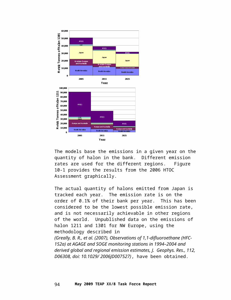
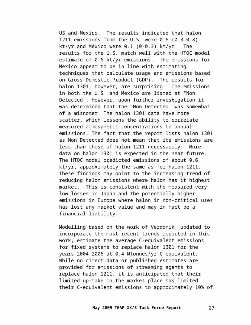
Unpublished data on the emissions of halon 1211 and 1301 for North Western Europe, using the methodology described by “Greally” in 2007, suggest that emissions of both halon 1211 and 1301 may have remained relativelyconstant or perhaps increased during the period when non-critical halon
May 2009 TEAP XX/8 Task Force Report6
systems had to be removed from service and halons had to be properly disposed of, in accordance with European Regulation (EC) No. 2037/2000. For both halon 1301 and halon 1211 the estimated installed base within Europe could be somewhat larger than the quantities reported to the European Commission as contained within Critical Uses.
In solvent applications, most of the ODS solvents like 1,1,1-trichloroethane (TCA) and CFC-113 have been in principle replaced by Not-In-Kind technologies. Therefore, HCFC and HFC (replacement) solvents are not belonging to the most important solvent sectors currently under development. It needs to be mentioned that HCFC-141b use as a solvent is still increasing in Article 5 countries, but this chemical is expected to be replaced by chlorinated (non MP controlled) solvents and other Not-In-Kind technologies in the near future, while applying appropriate safety considerations. HCFC-225 and some HFC solvents such as HFC-43-10mee, HFC-c447ef, HFC-245fa and HFC-365mfc have been used where non-ODS solvents were or are not available, in particular in solvent operations in non-Article 5 Parties. Some hydrofluoroethers (HFEs) could be replacement options for these HCFC and HFC solvents. However, there are a few specialty solvent applications that can still only be met with HCFC-225 (or 141b) or the original Class I ODS solvent (e.g., CFC-113). For example, the US Navy use of HCFC-225 (or HCFC-141b) to replace CFC-113 to clean shipboard oxygen producers. No other alternatives are available.
Inhaled therapy is essential for the treatment of patients with asthma and COPD and the numbers of inhalers used world-wide is increasing steeply. It is projected that metered does inhalers (MDIs) will use and emit ~7000 tonnes of HFCs (or 10,000 ktonnes CO2 equivalent) by the time the CFC transition will be completed by 2015. This will entail significant technology transfer to developing countries for local manufacture of affordable HFC MDIs, with financial support from the Multilateral Fund. However, local manufacturers in developing countries could switch to Dry Powder Inhaler (DPI) manufacture. DPIs are available for most inhaled drugs, and could replace the majority of propellant MDIs. Patients find them easy to use, and with local manufacture they are affordable.
In fire protection, banks of halons are expected to decrease much slower than was expected in the 2005 Supplement because the emission rates for halons are expected to be lower than predicted in the Supplement Report in 2005 (e.g., 50% lower in the year 2015). Emissions of HCFCs (and PFCs) are in the range of 100-130 ktonnes CO2 equivalent. Emissions of HFCs continue to grow in direct proportion to the increasing size of the bank of HFCs and are predicted to be about 4-6,000 ktonnes CO2 equivalent in the period 2015-2020 (for comparison purposes the emissions of HCFCs and HFCs in refrigeration and air conditioning are both predicted in the 400-600,000 ktonnes CO2 equivalent range during the period 2015-2020).
May 2009 TEAP XX/8 Task Force Report 7
In foam applications, the banks of CFCs are expected to diminish slowly to 6.75 Gtonnes CO2 equivalent in the period to 2020 but will still be the largest single bank in climate terms for the foreseeable future after that. The bank of HCFCs will largely stabilise in the period 2010 to 2020 with some shorter lifecycle applications (e.g. domestic refrigerators) being decommissioned in non-Article 5 countries while growth in bank size will continue in Article 5 regions. HFC banks are expected to grow to just under 1 million tonnes by 2020 unless pressure to move to lower-GWP solutions is brought to bear.
In contrast with the refrigeration and air conditioning sectors, emissions from foam banks vary between 1% and 3% of bank size annually depending on the maturity of the bank in question and the portfolio of applications covered. CFC emissions are expected to be around 1.25% of bank size in 2020, while HFC emissions will be running at about 3.1% annually at that time.
In refrigeration and air conditioning, the banks that are currently estimated for the year 2015 in a business as usual (BAU) scenario are slightly different from the ones estimated in the year 2005. They are lower for HCFCs (10%) and HFCs (25%) in stationary air conditioning; they are also estimated slightly lower for mobile AC. This again influences the level of the emissions estimated for 2015 and beyond. In the BAU scenario, global emissions total about 820 ktonnes for all refrigeration and AC sectors for all chemicals in the year 2015, a level which equates to about 1.4 Gtonnes CO2 equivalent.
If one compares the global banks (in the BAU scenario) between 2015 and 2020, the total HCFC bank is estimated to decrease, whereas the HFC bank is estimated to increase by about 30% in this five year period. A similar tendency can be observed in the emissions. HCFC emissions from the different sub-sectors generally decrease, with an average decrease estimated for all sectors of 7% between 2015 and 2020. Where it concerns the HFC emissions, growth is estimated in the BAU scenario to be between 4 and 63% in the different sub-sectors with a growth of 21% over all sectors.
In the BAU scenario, emissions for Article 5 countries would be about 500 ktonnes for all sectors in the year 2015, this being somewhat less than 0.8 Gtonnes CO2 equivalent for 2015. This means that as early as 2015, more than 60% of the global total emissions would come from Article 5 countries. If one compares the emissions between 2015 and 2020 in Article 5 countries, total HCFC emissions are estimated to level off (where there is estimated a sharp decrease in non-Article 5 countries). At the same time, the HFC emissions are estimated to increase by about 28% in this five year period (mainly in the domestic, industrial and stationary air conditioning sectors).
In a MIT (mitigation) global scenario (using currently available techniques and alternatives in the best way possible), HCFC emissions from the different
May 2009 TEAP XX/8 Task Force Report8
sub-sectors generally decrease, with an average decrease estimated for all sectors of 17% between 2015 and 2020 (compared to a 7% decrease in the BAU scenario for the same period). As regards HFC emissions, growth is estimated in the mitigation scenario between minus 16% and 50% in the different sub-sectors with a growth of 8% over all sectors (compared to a 20% growth in HFC emissions for the BAU scenario). Global emissions total at 610 ktonnes for all refrigeration and AC sectors for all chemicals in the year 2015, a level that equates to 1.0 Gtonnes CO2 equivalent in the MIT scenario. This level is expected to decrease to 0.92 Gtonnes CO2 equivalent by 2020.
In the MIT scenario for Article 5 countries, HCFC emissions from the different sub-sectors are generally expected to decrease between 2015 and 2020 (+15% to -40% dependent on the subsector), with an average decrease estimated for all (HCFC) sub-sectors of 10%. Where it concerns HFC emissions, growth is estimated over the period 2015-2020 in the MIT scenario in several sectors, with a modest increase of about 16% in the mobile AC subsector between 2015 and 2020. Totalled over the different sub-sectors this yields an increase of 26-30% in HFC emissions (30% in tonnes and 26% in CO2 equivalent); for comparison, HFC emissions in non-Article 5 countries are expected to remain virtually the same during 2015-2020.
Overall, however, total emissions in the MIT scenario in Article 5 countries are expected to decrease by about 5% between 2015 and 2020, with an increase in HFC emissions (25%).
With a significant market penetration of low GWP technologies, and good containment practices, it might well be that HFC emissions could stabilise in Article 5 countries in the 2020-2030 decade. This would be contrary to the growth sometimes considered as unavoidable for HFC emissions in Article 5 countries for the decades after 2020 (up to 2030-2040). It may be expected that this could result in a further decrease of total emissions (the sum of CFC, HCFC and HFC emissions) after 2020.
A more accurate estimate can be made in 4-5 years when the market penetration of different low GWP alternatives for various HCFC replacement technologies in the refrigeration and AC sectors will be more accurately known (in response to the accelerated HCFC phase-out schedule in the Article 5 countries, as well as to developments in non-Article 5 countries).
As a summary for HCFC and HFC banks and emissions for the period 2002-2020, the tables below highlight the numbers noted above for fire protection, foams and refrigeration and AC (in Mtonnes CO2 equivalent). They provide data for 2002 from the Supplement Report, the updated BAU and MIT scenario totals for 2015 and 2020 (which were derived in particular for the part describing the refrigeration and AC sectors), as well as the average of the BAU and MIT scenario data. Only average BAU-MIT values have been used
May 2009 TEAP XX/8 Task Force Report 9
in the analysis presented below (which then particularly yields a higher emissions growth than in the MIT scenario itself). Foams data were included for HCFCs and HFCs, where the HFC emissions have been estimated for non-Article 5 and Article 5 countries on the basis of a 90-10% estimate, respectively.
UPDATED 2009BANKS in Mt CO2 equivalent AVERAGE BAU-MIT MIT BAU MIT BAUyear 2002 2015 2020 2015 2015 2020 2020
HCFC WORLD 441 624 565 544 703 463 666HFC WORLD 208 558 644 459 656 493 794TOTAL WORLD 649 1181 1208 1003 1359 956 1460
The growth in the size of the banks between 2002 and 2020 is virtually zero for HCFCs, however, far larger for HFCs (growth by a factor of about five). There is not much difference between the MIT and the BAU scenario where it relates to the bank sizes (less than 10% for both 2015 and 2020); this is different for emissions. As can be seen in the table, the banks of HCFCs are expected to slightly decrease during 2015-2020, whereas banks of HFCs are forecast to further increase by about 30%. The total amount in banks in the world for all relevant sectors (i.e., refrigeration and AC, foams and fire protection) for HCFCs and HFCs are expected to increase by a factor of two between 2002 and 2020.
Both for HCFCs and HFCs the emissions are expected to increase between 2002 and 2020, with a substantial increase for HFCs. The global HCFC emissions are expected to slightly decrease (by about 10%) after 2015, whilst an increase in global HFC emissions is expected by 15-20% between 2015 and 2020. Part of this increase will be due to replacement of HCFCs with HFCs, while the remainder will be due to expansion of HFC use in certain sectors due to economic growth.
May 2009 TEAP XX/8 Task Force Report10
Total (i.e., the sum of HCFC and HFC) emissions are expected to increase in both non-Article 5 and Article 5 counties between 2002 and 2020, with a quite moderate increase in non-Article 5 countries and a much larger increase in Article 5 countries (by almost a factor of three). The growth is expected to be largest before 2015, with only a marginal global increase during the period 2015-2020. For the average of the BAU and MIT scenario, observations related to emissions from Article 5 and non-Article 5 countries for the period 2015-2020 are summarised as follows: No increase is expected in the sum of HCFC and HFC emissions in non-
Article 5 countries; a small decrease is expected in HCFC emissions in Article 5 countries;
and HFC emissions in Article 5 countries are expected to increase by almost
30%.
Further reductions in the size of the emissions can be realised by increasing the use of low GWP substances compared to the forecast and through applying additional, improved containment practices than so far anticipated. This tendency is clearly shown in the table in the MIT emissions, where substantially lower values for both the years 2015 and 2020 are recorded.
It should be born in mind that these values are based upon the values in tonnes multiplied with the GWPs for the different chemicals from the Second IPCC Assessment Report. They would all be 10-20% higher if the GWP values would have been used as published in the IPCC Fourth Assessment Report (AR4 WG I).
May 2009 TEAP XX/8 Task Force Report 11
2 Introduction
2.1 The Process
Decision XX/8 mentions “To request the Technology and Economic Assessment Panel to update the data contained within the Panel’s 2005 Supplement to the IPCC/TEAP Special Report and to report on the status of alternatives to hydrochlorofluorocarbons and hydrofluorocarbons, including a description of the various use patterns, costs, and potential market penetration of alternatives no later than 15 May 2009;”
TEAP established a Task Force to deliver an update of the data contained in the Panel’s 2005 Supplement Report and to report on various alternatives to HCFCs and HFCs.
The report describes (all known) alternatives for HCFCs and HFCs for the specific sectors and sub-sectors (status and sector market penetration, costs where available, energy efficiency (TEWI, LCA)) in a relatively small number of pages per chapter, while focusing on the 99% mainstream.
TEAP is aware that other alternatives to ODS, that are not HFCs, may have a significant GWP. For instance, there has been some debate on the contribution of sulfuryl fluoride, SO2F2 (an alternative to methyl bromide) to global warming due to a recently assessed high GWP (> 4,000). This issue is currently being analysed by the Science Assessment Panel and falls outside the scope of the work of the Task Force on Decision XX/8. A preliminary review can be found in the TEAP 2009 Progress Report in the progress chapter by the Methyl Bromide TOC.
This report starts with a number of chapters on various refrigeration and air conditioning sub-sectors. Chapter Lead Authors here were:Ed McInerney (domestic refrigeration)(RTOC);Denis Clodic (commercial refrigeration)(RTOC);Andy Pearson (large size refrigeration)(RTOC);Fred Keller (unitary air conditioning)(RTOC);Ken Hickman (chiller air conditioning)(RTOC); and Jürgen Köhler (mobile air conditioning)(RTOC).
The next two chapters describe polyurethane foam for insulation and non-insulation purposes and XPS foam; here the Chapter Lead Authors were Miguel Quintero (TEAP, FTOC) and Allen Zhang (FTOC).
Separate chapters deal with fire protection, solvents and inhaled therapy, where the Chapter Lead Authors were TEAP members Dan Verdonik (HTOC), Masaaki Yamabe (CTOC) and Ashley Woodcock (MTOC).
May 2009 TEAP XX/8 Task Force Report 13
Reviewing Authors for this report were Stephen O. Andersen (TEAP), Paul Ashford (TEAP, FTOC), Stéphanie Barrault (Ecole des Mines, Paris), Steve Bernhardt (CTOC), Nick Campbell (MTOC), Dave Catchpole (TEAP, HTOC), Daniel Colbourne (RTOC), Sukumar Devotta (RTOC), Martin Dieryckx (RTOC), William R. Hill (RTOC), Mike Jeffs (FTOC), Michael Kauffeld (RTOC), Lambert Kuijpers (TEAP, RTOC), Andrew Lindley (Ineos UK), Per Lundqvist (KTH Stockholm), Petter Nekså (RTOC), Roberto Peixoto (TEAP, RTOC) and Jürgen Süss (Danfoss Denmark).
The XX/8 Task Force has been co-chaired by TEAP members Lambert Kuijpers and Dan Verdonik, where all initial logistic issues (correspondence etc. concerning drafting, reviewing) were co-ordinated by Lambert Kuijpers.
In the table below, the Chapter Lead Authors and Reviewing Authors for the chapters describing the different (sub-) sectors are given. Five reviewing authors have given comments throughout the report (or were involved as original drafters for cross-sectoral chapters, see below). Four Chapter Lead Authors presented banks and emissions data for fire protection (Verdonik), foams (Ashford) and refrigeration and AC (Clodic, Kuijpers, with co-operation from Stéphanie Barrault).
May 2009 TEAP XX/8 Task Force Report
(Sub)-Sector Chapter Lead Author Reviewing Authors
Domestic refrigeration Ed McInerney Sukumar Devotta, Lambert Kuijpers
Commercial refrigeration Denis Clodic Daniel Colbourne, Michael Kauffeld, Roberto Peixoto, Jürgen Süss
Large size refrigeration Andy Pearson Per LundqvistUnitary air conditioning Fred Keller Petter Neksa, Jürgen Süss,
Per LundqvistChiller air conditioning Ken Hickman Martin Dieryckx,
Lambert KuijpersMobile air conditioning Jürgen Köhler Stephen Andersen, Denis Clodic,
William HillFoams (incl XPS foam) Miguel Quintero
Allen ZhangPaul Ashford, Mike Jeffs
Fire protection Dan Verdonik Dave CatchpoleSolvents Masaaki Yamabe Lambert KuijpersInhaled therapy Ashley WoodcockBanks and emissions Lambert Kuijpers
Paul AshfordDenis ClodicDan Verdonik
Stéphanie Barrault,(Chapter Lead Authors for the chapter parts by the others)
General Steve Bernhardt, Nick Campbell, Daniel Colbourne, Andy Lindley, Petter Neksa, Andy Pearson
14
The XX/8 Task Force was composed in the course of February 2009. First drafts of chapters were requested with a deadline of 14 March 2009. Several chapters received a large number of comments in the period 15 March-16 April 2009.
A consolidated draft of the report was composed by 19 April for circulation to all the Task Force members, with comments and suggestions requested before 22 April 2009.
In order to give a cross-sectoral overview of the potential of unsaturated HFCs, ammonia, carbon dioxide and hydrocarbons, it was planned to insert general overview chapters. Substantial efforts were undertaken by some of the “general” reviewing authors (as chapter Lead Authors) to draft these chapters. However, it turned out that these chapters had to rely very much on the sector and sub-sector information, which made it very difficult to merge both kind of approaches. There has been substantial involvement of all Task Force members in submitting comments and suggestions for the overview sections.
The resulting 22 April (consolidated) version of the report was reviewed by the TEAP at its meeting, held 26-30 April 2009 in Agadir, Morocco.
Given the difficulties encountered by the Task Force, TEAP decided to not further consider the overview sections for this XX/8 Task Force report. TEAP recommended to use the information that was presented in the cross-sectoral overview section drafts in near future reporting efforts for the 2010 TOC assessments.
Further comments from TEAP members were considered for insertion and the report was circulated to the XX/8 Task Force Chapter Lead Authors for several rounds of comments and suggestions. A last circulation was done to all XX/8 Task Force members. Several comments were submitted and were used for the composition of the semi-final draft.
This semi-final draft version of the report was subsequently submitted to the full TEAP for endorsement.
Comments were made which were taken into account to the degree possible. The report was then endorsed by the TEAP.
After the final TEAP review process and the endorsement, the report was finalised and submitted to UNEP the beginning of June 2009.
May 2009 TEAP XX/8 Task Force Report 15
2.2 Information in the Annexes; banks and emissions data
Annex 1 gives the complete text of decision XX/8. Annex 2 gives the viewpoint of the TEAP on the nomenclature of fluorochemicals2. Annex 3, 4 and 5 contain the updates of the data on banks and emissions as presented in the 2005 TEAP Supplement Report for (1) fire protection (Annex 3), (2) foams (Annex 4) and (3) refrigeration and AC (Annex 5). The updates include the data for the year 2015 (or the period 2002-2015), but they also include data extrapolated to the year 2020. Annex 5 gives the data for emissions in (all sectors of) refrigeration and AC, expressed in both ktonnes and ktonnes CO2 equivalent, whereas the data for banks have only been given in ktonnes. This was due to the fact that all data for all chemicals --including CFCs-- for the refrigeration and AC sub-sectors were re-evaluated at the time of the completion of the report; however, totals for HCFC and HFC banks were available and are given in this report.
The updated data for banks and emissions have been derived using practically the same assumptions for containment and recovery practices and the uptake of new refrigerants as in the TEAP Supplement Report. If regulations were in place at the time of the drafting of this report, their impact on banks and emissions has been estimated as adequate as possible. Data have not taken into account any assumptions on future policies or regulations regarding HCFCs or HFCs.
Compared to the 2015 data estimated in 2005 for the TEAP Supplement Report the updated data for banks and emissions are somewhat smaller because it has been assumed that there is lower growth in stationary air conditioning and a slightly lower growth in mobile air conditioning, here only during a certain period. Emission data for HFC-23 from HCFC-22 production have not been considered (due to developments in addressing its abatement under the CDM and possible further near future policy developments here).
Annex 6 gives an overview of aggregated HCFC and HFC banks and emissions data for non-Article 5 and Article 5 countries, as well as a summary of the global totals, expressed in both ktonnes and ktonnes CO2 equivalent. The table with banks and emissions in CO2 equivalent, together with an analysis of the data, is also presented in the Executive Summary.
2 Newly developed (low GWP) unsaturated HFCs are normally defined by the chemical manufacturers as “HFOs” (hydro-fluoro-olefins), derived from “olefins”, the historic name for unsaturated hydrocarbons. This in order to separate them from the common “HFCs”. The nomenclature issue is further addressed in Annex 2 of this report
May 2009 TEAP XX/8 Task Force Report16
3 Domestic Refrigeration
3.1 Background
Most domestic refrigerators and freezers are used for food storage in dwellings and non-commercial areas such as offices. Approximately 100 million units are produced annually. Storage volumes range from 20 litres/unit to 850 litres/unit. A typical product contains a factory-assembled, hermetically sealed vapour-compression refrigeration system employing a 50 to 250 Watt induction motor and containing 50 to 250 grams of refrigerant. The age distribution of the globally installed products is extremely broad with an estimated median age of 17-19 years at retirement. The long product life and high volume annual production combine for an estimated global installed inventory of 1500 to 1800 million units.
3.2 Refrigerant Options
Conversion of all new production domestic refrigerators and freezers from the use of ozone-depleting refrigerants is complete. Non-Article 5 Parties completed conversions by 1996, Article 5 Parties by 2008. The conversion of existing units to alternative refrigerants is strongly dependent on original product configuration. Informed technical assessment is essential to ensure product safety and performance are retained. Required modifications to maintain consumer needs can require a significant fraction of new product cost and has constrained broad conversion acceptance.
3.2.1 New Equipment Options
About 63 percent of current new production of domestic refrigerators and freezers employ HFC-134a refrigerant and slightly more than 35 percent employ hydrocarbon refrigerants. The remaining 1-2 percent employs either HFC-152a or HCFC-22, presumably due to regional availability. HC-600a is the primary hydrocarbon refrigerant used. Blends of HC-600a and HC-290 are used in some cases. These blends allow matching the volumetric capacity of previously used refrigerants to avoid capital investment to retool compressor manufacturing. These blends result in a small reduction in refrigerator energy efficiency. Either HFC-134a or HC-600a deliver comparable energy efficiency with design variation providing more difference than the refrigerant selection. Two issues of interest are (1) the partial second-generation migration from HFC-134a to HC-600a and (2) current preliminary suggestions of the use of low GWP unsaturated HFCs to replace HFC-134a.
Migration of automatic defrost new production refrigerators from HFC-134a to HC-600a is motivated by global warming considerations. Conversions began in Japan and have progressed to include the majority of new refrigerator production in Japan. A major U.S. manufacturer recently announced an intent to introduce auto-defrost refrigerators using the HC-600a
May 2009 TEAP XX/8 Task Force Report 17
refrigerant. Codes and standards modifications and approvals are currently in process and commercial introduction is anticipated in 2009.
Chemical manufacturers developed low GWP unsaturated HFC compounds for automotive air conditioning use. The theoretical assessment is that HFC-1234yf has the potential for comparable energy efficiency to HFC-134a in domestic refrigerators. Long-term reliability expectations for domestic refrigeration use are significantly more demanding than for automotive applications. Numerous application criteria need to be assessed before this refrigerant can be established as a viable alternative candidate in this sub-sector.
3.2.2 Service of Existing Equipment
Field service procedures typically use originally specified refrigerants. Acceptance of refrigerant blends developed for service use has been good where mandatory service regulations promote their use. Various blends are in use. Retrofit or conversion to hydrocarbon refrigerants has been successful for some product configurations.
Article 5 countries completed new equipment (OEM) conversions approximately 15 years ago. The final production legacy products are now approaching the end of their life cycle and service demand for legacy refrigerant is vanishing. In Article 5 countries the service demand for legacy refrigerants is expected to remain strong for at least a decade because of the delayed conversion of new production. Limited capital resources also favour a rebuild during service options in Article 5 countries versus the replacement by new equipment. This exacerbates the situation by further retarding conversion of the installed base to new production units. This rebuilding also voids an opportunity to significantly improve product energy efficiency of the installed base.
3.2.3 Not-In-Kind Alternative Technologies
Alternative refrigeration technologies continue to be pursued for applications with unique drivers such as portability or no access to electrical energy distribution network. Technologies of interest include the Stirling cycle, absorption cycle, thermoelectric refrigeration (Peltier), magnetic cycles etc. In the absence of unique drivers such as the examples cited above, no identified technology is cost- or efficiency-competitive with conventional vapour-compression technology for mass-produced domestic refrigeration equipment.
3.2.4 Product Energy Efficiency Improvement Technologies
Relative energy efficiency provides a direct nexus to the relative global warming potential of refrigeration technology options. Energy labelling and energy regulations are widely used to promote improved product energy
May 2009 TEAP XX/8 Task Force Report18
efficiency. Various energy test procedures have the intent to relate to consumer energy consumption. Each test procedure is unique. Results from one should never be directly compared to results from another. Significant technical options to improve product energy efficiency have already demonstrated mass production feasibility and long-term reliability. Both mandatory and voluntary energy efficiency initiatives have catalysed industry product efficiency development efforts. Extension of these to all domestic refrigerators would yield significant benefit, but requires availability of capital funds. Additional technical options for significant energy efficiency improvement presently have limited application. These premium-cost options are restricted to high-end models or require supplemental incentives to proliferate their use at this stage of maturity. Options include variable speed compressors, adaptive controls, dual evaporators and improved thermal insulation.
3.2.5 Refrigerant Annual Demand
Domestic refrigeration annual refrigerant demand is not reported but can be estimated using reasonable assumptions. Figure 3-1 illustrates the refrigerant selection, the demand and the trend over a 16-year span for new refrigerator production.
May 2009 TEAP XX/8 Task Force Report 19
Data are not available to reasonably predict global refrigerant demand for field service. Crude estimates suggest a 3 to 5 total ktonnes annual global demand. Approximately one-half is estimated to be legacy refrigerant and the remaining one-half is expected to be currently used refrigerants to service new production units. The demand trend is expected to be stable because of the high inertia inherent in the large installed base. Service refrigerant demand is expected to continue to be for originally specified refrigerants: primarily CFC-12 for legacy product and either HFC-134a or HC-600a and HC-290 for new production. Mandatory service regulations could promote the use of refrigerant blends for service and reduce emissions of ODS refrigerants through CFC-12 use reduction.
May 2009 TEAP XX/8 Task Force Report20
4 Commercial Refrigeration
4.1 Refrigerants in use in commercial refrigeration
Commercial refrigeration includes three different categories of systems: stand-alone equipment, condensing units, and supermarket centralised systems. The three categories are structured in different ways and the refrigerant choices depend on the refrigerating capacity: for stand-alone equipment, HFC-134a is the dominant refrigerant,
replaced by HC-600a in some bottle coolers and water fountains and by HC-290 in other equipment types such as ice cream freezers.
for condensing units and centralised systems, the dominant refrigerant is HCFC-22, which has been replaced in new centralised systems by R-404A, and is replaced by several “intermediate” HFC blends designed for the retrofit of current installations.
The number of supermarkets world-wide is estimated at 530,000 in 2006 covering a wide span of sales areas varying from 500 m2 to 20,000 m2. The populations of vending machines, stand-alone equipment, and condensing units are evaluated at 20.5, 32, and 34 million units, respectively. In 2006, the refrigerant bank was estimated at 547,000 tonnes and it is split as follows: 60% in centralised systems; 33% in condensing units, and 7% in stand-alone equipment. The estimate of refrigerant types sharing in 2006 is about 30% CFCs, 55% HCFCs, and 15% HFCs.
Due to high refrigerant leakage rates, commercial refrigeration causes more refrigerant emissions in terms of CO2 equivalent (considering the GWP of CFC, HCFC and HFC refrigerants) than any other refrigeration application when the GWP of CFC and HCFC refrigerants are accounted for. The total emissions expressed in CO2 equivalent are about 584 million tonnes. Centralised systems with long piping circuits have led to large refrigerant charges (300 to 3,000 kg depending on the size of the supermarket) and consequently to large losses when ruptures occur, representing 70% of emissions. Over the last 10 years, a number of technical improvements have been made to limit refrigerant emissions and their environmental impact, and to reduce the refrigerant charge by developing indirect systems and using refrigerants with lower GWP.
4.2 Refrigerant Options for New Systems
4.2.1 Stand-alone Equipment
Stand-alone equipment integrates all refrigerating components within its structure. They are also called plug-in systems because the only thing to be done for their installation is to insert the electric plug into a socket. Stand-
May 2009 TEAP XX/8 Task Force Report 21
alone equipment, including freezers and all kinds of small equipment, are used extensively in many Article 5 countries. It has to be underlined that for most of those systems, the refrigerating circuit is virtually hermetic and emissions during the entire lifetime are very low. The refrigerant release takes place at the end of life and recovery has to be effective in the decommissioning phase, which could be encouraged by comprehensive containment policy.
The majority of stand-alone equipment is based on HFC-134a technology but for low-temperature equipment R-404A can also be used. The small refrigeration capacity has led to the use of hydrocarbons, keeping usually the refrigerant charge under 150 g.
In water fountains, some large beverage companies have switched from HFC-134a to isobutane (R-600a). For ice-cream freezers, a growing proportion of equipment has been converted from HFC-134a to propane (HC-290). For vending machines at the larger end of the scale, CO2 has been chosen as the refrigerant, the main reason being the avoiding of large charges of flammable refrigerants; this at the cost of a lower performance at higher ambient temperatures.
In summary, HFC-134a fulfils the technical constraints in terms of reliability and energy performance for stand-alone equipment. When the GWP of HFC-134a is considered prohibitive in relation to the HFC emissions that could occur, either (1) a very stringent policy for recovery at end of life has to be implemented or (2) a refrigerant such as HC-600a or HC-290 should be used as a replacement. The latter provided that the refrigerant charge can be kept below certain (acceptable) levels. Many equipment manufacturers have accepted the recommendation of 150 g of hydrocarbons per piece of equipment as the reference limit. CO2 is also being introduced, particularly in moderate climates, even with uncertainties regarding the performance in relation to the investment and regarding the operating costs in comparison to the ones for other refrigerants. It is estimated that all refrigerants banked in stand-alone equipment represent an amount of about 38,000 tonnes globally.
4.2.2 Condensing units
Condensing units, comprising the second group of commercial refrigeration equipment, are composed of: one (or two) compressor(s), one condenser, and one receiver assembled into the condensing unit, which is located external to the sales area. The refrigeration equipment consists of one or more display case(s) in the sales area and/or a small cold room. Systems using condensing units are installed in many Article 5 countries. New equipment can use HFC-134a, HCFC-22, R-404A, R-407C, R-507, other HFC and HCFC blends, and HC refrigerants. HFC-134a, HCFC-22 and R-404A are the dominant refrigerants. The refrigerant charges vary from 500 g up to 20 kg. HFC-134a is only used for the lower capacity part of this segment; if the refrigeration
May 2009 TEAP XX/8 Task Force Report22
capacity is larger than 2 kW, HCFC-22 or R-404A are chosen because the large cooling capacities of these refrigerants lead to lower initial costs. The usual choices are not different in comparison to large commercial refrigeration, but the cost constraints are strong, and therefore the design of condensing units has to remain simple. Although in the ranking it is not the high priority candidate, CO2 is definitely offered as a possible option for this type of equipment. It should be noted that in Northern Europe, HC-290 or even HC-1270 are used as refrigerants. However, this has not been the choice over the last decade since the globally installed base still uses HCFC-22, and mainly R-404A in Europe. All refrigerants banked in condensing units are estimated to be in the order of 180,000 tonnes.
4.2.3 Centralised Systems
Centralised systems use racks of compressors installed in a machinery room. A number of possible designs exist; some are more used in certain countries such as distributed systems in the USA.
Direct expansion systemsThe dominant design is the direct expansion centralised system: the refrigerant circulates from the machinery room to the sales area, where it evaporates in heat exchangers installed in display cases, and then returns as vapour to the compressor racks. The refrigerant piping may extend from one to several kilometres. In the machinery room, racks of multiple compressors are installed with common suction and discharge lines, and each rack is associated with an air-cooled condenser (in a few cases a water cooled condenser can be used). Specific racks are dedicated to low temperature and others to medium temperature cycles.
For low temperature applications (-35 to -38°C evaporating temperature), the refrigerant has been R-502, a blend of CFC-115 and HCFC-22; it was widely used in Europe, however, much less elsewhere. HCFC-22 has been and is still the most used refrigerant in commercial centralised systems globally. In 2006, the HCFC-22 banked in those systems amounted to about 328,000 tonnes. The emission rates vary significantly dependent in a first instance on the size of the food sales area; the larger the number of display cases, the higher the emission rate, for the same type of containment policy. The annual emission rates vary from 15 to 35% in non-Article 5 countries, and can even be larger in Article 5 countries; those emission rates have to be analysed during a period of several years before one is able to draw definitive conclusions. The only way to avoid anecdotal references is to make cross-checks with the sales of refrigerants; this indicates at emissions in the range of 15-20% for small supermarkets and in the range of 20-30 % for large ones. These numbers are valid for most developed countries (except for the Netherlands due to its specific regulation).
May 2009 TEAP XX/8 Task Force Report 23
Direct systems using CO2 (R-744) as a refrigerant in either a trans-critical or subcritical cycle have been introduced in several countries, mainly in Europe. CO2 offers very good properties for heat recovery, which is often desirable in supermarkets for a substantial period of the year, even in climates with higher outdoor ambient temperatures. This then contributes to an overall favourable energy efficiency for these types of systems.
In order to drastically limit refrigerant charges, which vary from 300 kg to 3,000 kg depending on the size of the supermarket, two series of designs have been introduced over the last 10 years: distributed systems and indirect systems.
Distributed systemsThe layout of supermarkets in the United States presents common and unique characteristics for many of them. Dairy and deli products as well as meat are put in display cases around the sales area, and not displayed on long aisles. This lay-out makes installing distributed systems an easy job; these systems are characterised by: compressors installed in sound-proof boxes near the display cases, water condensers also installed in the boxes, which release their heat
through a water circuit connected to dry-air coolers having the same structure as air cooled condensers.
The refrigerant charge is reduced by about 30-50% depending on the design. Nonetheless, the market share of supermarkets with this concept is limited and has not spread out of the U.S.
Indirect systemsIndirect systems have been introduced in Europe first. They are composed of two or three circuits: the primary circuit where the refrigerant is contained in the machinery
room and where the air condensers are usually located on the roof of the supermarket. The refrigerant evaporates in a primary evaporator and cools a heat transfer fluid (HTF, also called “secondary refrigerant”).
once cooled, the HTF is pumped to the display cases where it absorbs heat in an air heat exchanger which cools the air, and is then transported back to the primary heat exchanger.
the other secondary loop equipped with another heat transfer fluid (also called a coolant fluid) is used in the system to transport the heat rejected from the condensers in the machine room, to the dry-air coolers on the roof.
The long circuits between the machinery room and the display cases do not contain any refrigerant but only secondary refrigerant (HTF); the refrigerant charge in the total circuit can therefore be reduced by at least 50% to 80%.
In Northern European countries, especially in Denmark, Sweden and, to a lesser extent, in Germany and the UK, non-HFC refrigerants have been
May 2009 TEAP XX/8 Task Force Report24
introduced over the last 10 years. Where the use as a primary refrigerant is scarce for ammonia (R-717), hydrocarbons (HC-290 or HC-1270) are more often selected as the primary refrigerants for the refrigerating system installed in a machinery room. The refrigerant charge of R-717 as well as the charge of hydrocarbons can be reduced by 90% compared to the usual HFC refrigerant charge because of the higher latent heat of vaporisation (in the case of ammonia) and because of the lower liquid density and the specific equipment design for hydrocarbons. CO2 (R-744) is not only used as a HTF but also as primary refrigerant in cascade systems.
The share of those non-HFC refrigerating systems in the total is difficult to establish precisely and is estimated to be 5% of the installed base of centralised systems in the countries it concerns.
Many indirect systems have also been designed using R-404A as the primary refrigerant in the machinery room (or outside). With the reduction of the charge, the reduction of the environmental impact via the reduction of HFC emissions is significant.
Well-designed indirect systems can be as efficient as direct systems due to better heat exchange in the air coils in the display case. However, heat transfer fluids used in indirect systems need special attention, especially at low temperatures where the pumping power may become excessive because of increased viscosity; the pumps have to be carefully chosen in order to avoid a significant increase in energy consumption in that case.
For indirect systems, CO2 can be used as a heat transfer fluid and as a refrigerant. The use of CO2 as a HTF is mainly done for low-temperature display cases and cold rooms. A unique characteristic of CO2 as a HTF is that it can partially evaporate in the display-case evaporators, with two-phase flow entering the primary evaporator. This evaporation scheme is very efficient: no superheat is present at the outlet of the display case. Moreover, the pumping power is not significant due to the low viscosity of the CO2. Taking into account the total energy consumption of all components, the energy efficiency of the low-temperature, CO2 based indirect system can be as good as the energy consumption of a direct expansion system.
For the medium temperature levels, several HTFs are competing: - CO2 (scarcely used due to its high pressure level in the range of 2.5 MPa);- MPG (Mono-Propylene Glycol, actually “propylene glycol”), still the
most common, as well as brines and some alcohols, and - different blends of acetate and formate potassium with water. Ice-slurry, which consists of a blend of “soft” ice and MPG, is still in its early development, where the cost of the soft ice generator is still high and the auxiliary power consumption of the scraper needs optimisation.
May 2009 TEAP XX/8 Task Force Report 25
Cascade systemsCO2 is used as a refrigerant in the low-temperature stage with an evaporating temperature around -35°C and a condensing temperature at the -12°C level, keeping the pressure tubing and the components below the 2.5 MPa pressure threshold for current technologies. The condensation of this CO2 low-temperature stage rejects its heat either directly in an evaporator / condenser or to a heat transfer fluid circuit. The condensation heat produced by the CO2 system is therefore delivered at the medium-temperature stage and then released outdoor by the medium-temperature vapour compression system. These concepts have been used in very large supermarkets and are claimed to have the same initial costs as R-404A direct systems, because the R-404A charge is reduced from about 1500 to less than 250 kg.
May 2009 TEAP XX/8 Task Force Report26
5 Industrial Refrigeration
The large equipment sector, also called “industrial equipment”, covers refrigeration, heat pump and process air conditioning plants in the size range of 100kW and upwards, with operating temperatures ranging from -50oC to +20oC. This does not, however, include large chillers for comfort cooling, which typically use centrifugal compressors operating on a fluorocarbon refrigerant, or centralised supermarket refrigeration systems, which use HCFCs or HFCs.
Large refrigeration systems predominantly use ammonia as refrigerant unless there are compelling local reasons to avoid it. The reasons for ammonia’s popularity are the relatively low capital cost for the equipment combined with its excellent operating performance. In some countries, for example the United States of America, the industrial sector was slow to shift to CFCs in the post-war era, and so retained a large stock of ammonia equipment. In Europe there was a greater shift away from ammonia from 1970 onward, particularly to the CFC based blend R-502, which was well suited to small, simple packaged systems. The phase-out of CFCs prompted a shift to HCFC-22 in some systems, but for low temperature applications plant this refrigerant was generally less reliable. In other cases a swift return to ammonia could be observed, but that applied to modern systems, characterised in comparison to traditional ammonia plants as requiring less refrigerant charge, and with a more automated operation. National markets within Europe responded differently to the CFC phase-out. Scandinavian countries, the United Kingdom and the Republic of Ireland returned to ammonia relatively easily. France, Italy and Spain used more HFC equipment in the industrial sector, mainly due to higher levels of bureaucracy associated with the ammonia use. In Central Europe, including Germany, Austria and Switzerland there was a marked return to ammonia, but not as quickly or completely as in Northern Europe. However increased restrictions on HCFC use have encouraged that trend to continue so that, by the turn of the century, the use of ammonia was as common in Central Europe as it is further north. In Eastern Europe and in the Russian Federation older ammonia systems are still commonly in use, however, these are often in poor condition. Some modern facilities have been constructed in India and China using ammonia as refrigerant with the equipment supplied by European or American multinationals. The designs of these facilities conform to European or North American standards but there is a strong need for ongoing training in operation and maintenance of these facilities.
In Article 5 countries, where the HCFC phase-out is on a slower time-scale than in the non-Article 5 ones, the use of HCFC-22 in industrial systems is still very widespread.
May 2009 TEAP XX/8 Task Force Report 27
There is an emerging trend towards the use of carbon dioxide in industrial systems when direct ammonia systems are not feasible, either in cascade with low charge ammonia or HFC systems, or in two stage systems with heat rejection at supercritical pressures. In 2008, a distribution warehouse was commissioned in Denmark, which provided 1500 kW of cooling capacity in chill and freezer storage rooms, and delivered about 1200 kW to a local district heating system from a trans-critical carbon dioxide refrigeration system. Carbon dioxide is very cost effective when applied in this way, together with integrated heating and cooling requirements. If this type of system becomes more common it would be possible that Article 5 countries that would move away from HCFCs will not use large HFC or ammonia systems, but will develop carbon dioxide solutions to suit their own requirements. Carbon dioxide is most suitable in colder climates where it is easier to make systems as efficient as current installations using different refrigerants. Some further equipment development is required if these systems are to be accepted in warmer climates such as the ones found in southern Europe, southern United States, Latin America and most of Asia.
In large petrochemical facilities, where the whole facility is engineered to avoid ignition sources, hydrocarbons are sometimes used. In these systems the refrigeration cycle is the same as applied in standard equipment, and its efficiency is generally good. Equipment can be engineered for evaporation temperatures from -50oC to 20oC by selection of the hydrocarbon; wide-glide mixtures of ethane and propane, with up to 20K temperature glide during the evaporation and condensation, have been used to further improve efficiency in auto-cascade systems. Care must be taken to avoid oil foaming in screw and reciprocating compressors, because of the extreme miscibility of the refrigerant in the oil.
May 2009 TEAP XX/8 Task Force Report28
6 Unitary air conditioning
6.1 Description of Product Category
On a global basis, air-cooled air conditioners and heat pumps ranging in size from 2 to 420 kW comprise a vast majority of the air conditioning market below 1,500 kW capacity. Nearly all air-cooled air conditioners and heat pumps manufactured prior to 2000 used HCFC-22 as their working fluid.
Air-cooled air conditioners and heat pumps generally fall into four distinct categories, based primarily on capacity or application: small self-contained air conditioners (window-mounted and through-the-
wall air conditioners); non-ducted or duct-free split residential and commercial air conditioners; ducted split residential air conditioners; and ducted commercial split and packaged air conditioners.
6.2 Current Situation
6.2.1 Primary HCFC-22 Replacements
In the developed countries, HFC refrigerants have been the dominant replacement for HCFC-22 in all categories of unitary air conditioners. The most widely used replacement is R-410A, a blend of two HFC refrigerants. The next most widely used replacement is R-407C, which is another HFC blend containing three HFC refrigerants. Systems using R-407C require(d) less redesign than those using R-410A because R-407C exhibits performance and operational characteristics very similar to those of HCFC-22. However, over time the industry has converted more products to R-410A because of its size, cost and serviceability advantages.
Hydrocarbons have been used in some low charge applications; including lower capacity portable room units and split system air conditioners. The use of flammable refrigerants is limited by current building codes (in certain countries or regions) and product design and safety standards. The international standard IEC 60335-2-40 describes the limits for use of flammable refrigerants for air conditioners and heat pumps. Broader use of hydrocarbon refrigerants in unitary air conditioners will be much more difficult, because the vast majority of unitary air conditioners have much higher charge levels than the small portable and split system air conditioners where hydrocarbons have successfully applied.
In addition to performance (capacity and efficiency), Life Cycle Climate Performance (LCCP), product safety and the energy efficiency at peak load need to be evaluated to determine the optimum solution. The energy efficiency at peak load is important because of the peak electricity demand that air conditioners impose on the utility grid.
May 2009 TEAP XX/8 Task Force Report 29
6.2.2 Developed Country Status
The transition away from HCFC-22 is nearly complete or well underway in most developed countries. The phase-out of HCFC-22 in the manufacturing of new products in the EU occurred in 2004. The phase-out in North America and Japan is to be completed in 2010; Japan has already phased out the use of HCFC-22 in nearly all-new products. In North America less than 50% of new products still utilise HCFC-22; with a complete phase-out of HCFC-22 required in January 2010. While the EU, Japan and North America are the dominant producers and users of unitary air conditioning products among developed countries, other developed countries have either already phased out HCFC-22 or are currently phasing out the usage, production or imports of HCFC-22 based air conditioners following the timetable set by the latest adjustments to the Montreal Protocol.
6.2.3 Developing Country Status
Most developing countries are continuing to utilise HCFC-22 as the predominate refrigerant in unitary air conditioning applications. The two largest developing country markets are China and India.
China has grown to become the largest producer of air conditioners world-wide. The air conditioner production in China supports both a rapidly increasing local market and a growing export market. China currently has the capability of producing both HCFC-22 and R-410A air conditioners. The HCFC-22 air conditioners serve both the domestic and remaining HCFC-22 export markets, while the R-410A products are being produced primarily for export to developed countries.
With the recently approved adjustment to the Montreal Protocol (the accelerated HCFC phase-out, which mainly changed the phase-out schedule for developing countries) developing countries are expected to start to increase actions regarding the HCFC refrigerant replacement, including the elaboration of HCFC Phase-out Management Plans (HPMP) supported by the Multilateral Fund of the Montreal Protocol.
6.3 Potential HFC Replacements
While R-410A and R-407C both have zero ozone depletion potential, both of these refrigerants have a high global warming potential. Therefore the air conditioning industry is currently exploring alternatives to these refrigerants, which have lower global warming potentials and/or better Life Cycle Climate Performance. However, the current candidates create new technical challenges of flammability, toxicity, peak load efficiency and economic feasibility. Some of the candidate HFC replacements are described in the following section. It is anticipated that additional candidates may emerge as research into new low GWP refrigerants continues.
May 2009 TEAP XX/8 Task Force Report30
6.3.1 HFC-32
HFC-32 is one of the primary constituents of both R-410A and R-407C. It is a pure HFC, which exhibits higher capacity and efficiency than R-410A. HFC-32 also has a GWP approximately 29% of that of R-410A, which makes it a lower GWP alternative to R-410A. HFC-32 has been given an “ASHRAE A2 flammability” rating with a relatively low flame speed. The flammability would need to be mitigated in the design of the product.
6.3.2 HFC-152a
HFC-152a has performance and thermo-physical characteristics similar to those of HFC-134a. It has similar capacity and efficiency performance to that of HFC-134a. R-152a has a much lower GWP than HFC-134a, R-410A or R-407C. R-152a has an “ASHRAE A2 flammability rating”, with a relative high flame speed. Mitigation of the flammability issues would be more difficult with HFC-152a than with HFC-32 and could possibly require limiting the maximum refrigerant charge or the use of secondary loops. In addition, significant redesign of existing HCFC-22, R-410A or R-407C systems would be required for them to use HFC-152a.
6.3.3 HFC-1234yf
HFC-1234yf has a very low GWP and thermodynamic performance characteristics similar to HFC-134a. To date, the primary application for this refrigerant is targeted to be the MAC sector (see chapter 8). HFC-1234yf is a lower pressure refrigerant than R-410A and HCFC-22. Therefore, air conditioning systems, which almost universally utilise HCFC-22 or R-410A today, would require significant redesign to utilise this refrigerant. The design changes (similar to the ones needed for application of HFC-134a) would include larger displacement compressors, larger heat exchangers, and modified refrigerant circuiting to match the performance (capacity and efficiency) of current HCFC and HFC systems. Future developments might include higher pressure unsaturated HFCs, for which such redesigns would not be required.
6.3.4 Hydrocarbon Refrigerants
HC-290 (propane) is the most likely hydrocarbon refrigerant to be applied in air conditioning applications. Propane has performance characteristics very close to that of HCFC-22. The most significant issue involved in the application of propane is addressing its very high flammability rating, “A3”.
Propane has been applied in some low charge applications, in less than 500 g containing portable units and in less than 300 g split system units. Because of the low density, the charge of a HC-290 unit is about 40% of the charge of a
May 2009 TEAP XX/8 Task Force Report 31
HCFC-22 unit. IEC standard 60335-2-40 has established the maximum charge limits for these applications.
Safely and cost effectively applying propane to typical unitary systems requiring significantly higher refrigerant charges will be a significant technical challenge. One approach is the utilisation of a secondary refrigerant loop. However, this approach has been shown to introduce significant cost and/or performance penalties. Approaches such as leak testing and pump down circuits could be more viable for improving safety aspects.
6.3.5 CO2
CO2 is the ideal refrigerant from the perspective of ODP and GWP. However, CO2 does have an acute toxicity level, which may put restrictions on its use in occupied spaces. Also, the high critical point temperature of CO2 results in significant efficiency losses when it is applied at the typical indoor and outdoor air temperatures of unitary air conditioning applications.
Considerable research is being conducted to identify cycle modifications that can offset these losses. These cycle modifications generally fall into the addition of intra-cycle heat exchanger processes and/or the addition of ejectors or expanders to recover some of the losses of the expansion process. The addition of efficiency enhancing components is expected to add significant cost to CO2 systems, resulting in systems more expensive to produce than current HCFC-22 and R-410A systems.
6.4 Summary
Currently, the HFC refrigerant blends R-410A and R-407C are the most applied replacements for HCFC-22. At this moment in time, the industry is in the very early stages of the process of developing and applying low GWP alternatives in Unitary Air Conditioning applications. There are several alternatives, which are showing promise including hydrocarbons and CO2 with possibilities for new low GWP HFCs. However, the development of products with these options is expected to require significant additional research and development. Therefore, the responsible use of HFCs is the near term solution to achieve the best LCCP for unitary air conditioners.
May 2009 TEAP XX/8 Task Force Report32
7 Chiller air conditioning
7.1 Description of Product Category
Comfort air conditioning in commercial buildings and building complexes (including hotels, offices, hospitals, universities) is commonly provided by water chillers coupled with chilled water distribution and air handling and distribution systems. Chillers are used for air conditioning in industrial processes such as textile manufacturing and printing. In these applications chillers cool water or a water/antifreeze mixture which is pumped through a heat exchanger in an air handler or fan-coil unit for cooling and dehumidifying the air. Chillers also are used for providing chilled water for process cooling in industrial applications.
7.2 Types of Chillers
Vapour compression chillers: The principal components of a vapour-compression chiller are a compressor driven by an electric motor (or less commonly an engine or turbine), two heat exchangers - a liquid cooler (evaporator) and a condenser, a refrigerant, a refrigerant expansion device, and a control unit. The refrigerating circuit in chillers usually is factory sealed and tested; no connection between refrigerant-containing parts is required on site by the installer. Leaks during installation and use are minimised accordingly. An exception is for very large units for which compressors and heat exchangers are separated for shipping due to large size. Vapour compression chillers are identified by the type of compressor they employ. They are classified as centrifugal (turbo) compressors or positive displacement compressors. The positive displacement category includes reciprocating piston, screw, and scroll compressors. Chillers can be further divided according to their condenser heat exchanger type; water-cooled, air-cooled, and evaporatively-cooled.
Water-cooled chillers generally employ cooling towers for heat rejection from the system. Air-cooled chillers are equipped with refrigerant-to-air condenser coils and fans to reject heat to the atmosphere.
There also are evaporatively-cooled chillers. Heat from the condensing refrigerant is rejected to the air in a coil, which is continually wetted on the outside by a recirculating water system. Air is directed over the coil causing a small portion of the water to evaporate to help cool the coil. There is no circulation of water from the condenser to the chiller. Most of these chillers are supplied without the condenser which is added in the field. This requires refrigerant pipework at the installation site.
May 2009 TEAP XX/8 Task Force Report 33
The selection of water-cooled, air-cooled, or evaporatively-cooled chillers for a particular application varies with regional climate conditions, water availability for water-cooling, owner preferences, and operational and investment cost evaluations.
Absorption chillers: Absorption chillers employ a different technology, which is based upon the absorption cycle. This type of chiller does not use HCFCs or HFCs. The energy source for absorption chillers is heat provided by steam, hot water, or a fuel burner. In absorption chillers, the compressor and motor of the vapour-compression cycle are replaced by two heat exchangers (a generator and an absorber) and a solution pump. The refrigerant in these systems commonly is water and the absorbent usually is lithium bromide, though lithium chloride also was common in the past and is still used infrequently. Small absorption chillers may use an alternate fluid pair: ammonia as the refrigerant and water as the absorbent. This fluid pair also is used for lower temperatures (below 0o C). Absorption chillers are a Not-In-Kind alternative to vapour compression chillers. They are manufactured and applied primarily in the Asia-Pacific region, particularly in Japan, China, India, and South Korea. Smaller quantities are used in Europe, India, and North America.
Table 7-1 lists the cooling capacity range offered by single units of each type of chiller (many applications use multiple chillers).
Table 7-1: Chiller Capacity Ranges
Chiller Type Cooling Capacity Range (kW)
Scroll and reciprocating water-cooled 7 – 1,600Screw water-cooled 140 – 10,000Positive displacement air-cooled 35 – 1760Centrifugal water-cooled 200 – 30,000Centrifugal air-cooled 200 – 1,500Absorption Less than 90; 140-17,500
This report is an update on the status of alternatives to the refrigerants employed in vapour compression chillers, so the remainder of this chapter 7 will focus on those systems.
7.3 Current Situation
7.3.1 Primary HCFC-22 Replacements in New Chillers
In the developed countries, chillers with positive displacement compressors employed HCFC-22 until the Montreal Protocol phase-out date, 2010, approached for this refrigerant’s use in new equipment. (Europe phased out HCFC-22 in 2004.) . A portion of the market, particularly for chillers below 350 kW capacity, initially converted to the R-407C refrigerant, which has
May 2009 TEAP XX/8 Task Force Report34
physical and thermodynamic properties similar to those of HCFC-22. However, R-407C is a non-azeotropic mixture with an appreciable temperature glide (4-5 K), which negatively affects heat transfer. Chillers with R-407C require larger, more expensive heat exchangers to achieve competitive performance. The temperature glide makes R-407C unsuitable for use in larger chillers, which employ flooded evaporators.
Reciprocating compressors, used for many years in HCFC-22 chillers, are being displaced in new products by screw and scroll compressors. For screw compressor chillers, the transition away from HCFC-22 (and R-407C) to HFC-134a was under way by 2005 or earlier in developed countries. Scroll compressor chillers began to employ HFC-134a or R-410A to deal with the phase-out of HCFC-22. The transition is just getting under way in Article 5 countries, which have later phase-out dates for HCFC-22. HCFC-22 refrigerant is very much cheaper than the common alternatives and development expenditures for new chillers and compressors is therefore postponed in these countries.
Chillers with R-717 (ammonia) as the refrigerant are available with screw compressors in the capacity range 100-10,000 kW. Chillers with reciprocating compressors are available in the capacity range 20-1600 kW. R-717 chillers are manufactured in small quantities compared to HFC chillers of similar capacity. Applications in comfort cooling have been less common than in process cooling and the primary market for R-717 chillers has been Europe. HC-290, a hydrocarbon (propane) with refrigerant properties similar to those of HCFC-22, is used in chillers in industrial applications. HC-290 and another hydrocarbon, HC-1270, are used in a smaller number of chiller installations in Europe in banks, hospitals, schools, universities, data centres, and similar facilities. Some of the Article 5 countries such as Indonesia, Malaysia, and the Philippines are applying hydrocarbon chillers to large space cooling needs.
7.3.2 Centrifugal Chillers
Chillers with centrifugal compressors generally did not use HCFC-22. When CFC refrigerants were phased out, this class of chillers began to employ HFC-134a or HCFC-123 as refrigerants. Centrifugal chillers in developed countries and in Article 5 countries alike employ the same refrigerants, i.e., HFC-134a or HCFC-123 (HCFC-123 is no longer allowed in new chillers in Europe). HCFC-123 remains under the common phase-out schedule. There are no replacements that have been commercialised yet to replace either refrigerant for centrifugal chillers. HFC-245fa was developed as a foaming agent and is available for use in centrifugal chillers. Its use has been limited and does not seem to be increasing. HFC-245fa operates at volume flow rates and pressure levels in evaporators and condensers, which are intermediate between the levels of
May 2009 TEAP XX/8 Task Force Report 35
HCFC-123 and HFC-134a. Centrifugal chillers must be designed specifically for HFC-245fa; it is not a drop-in replacement for either HCFC-123 or HFC-134a.
7.3.3 Primary HCFC-22 Replacements in Existing Positive Displacement Chillers
Positive displacement chillers employing HCFC-22 refrigerant can be kept in operation by changing to HFC refrigerants. R-407C can be used as an alternative in systems, which do not employ flooded evaporators. The conversion from HCFC-22 to R-407C requires a change in lubricants and other important steps that have been established. The manufacturer of the chiller should be consulted to assure that all factors, including material compatibility, have been taken into account.
A number of “service fluids”, normally HFC blends, have been developed to replace HCFC-22 in existing equipment. When R-407C or one of the service fluids is used in an existing system, there will be changes in cooling capacity and power consumption. The extent of these changes has generally not been quantified by laboratory testing. Manufacturers’ warranties may not be supported after a conversion away from HCFC-22.
7.4 Potential HFC Replacements
7.4.1 Low GWP Refrigerants
7.4.1.1 HFC-1234yf
This refrigerant is similar in characteristics to HFC-134a. It has potential application in the range of screw and centrifugal compressor chillers that are manufactured today. Data on the performance obtainable with this refrigerant in chillers are not yet available. The design changes needed to optimise systems to use this refrigerant and their costs are not known either. Safety concerns with the use of this lower flammability refrigerant also need to be evaluated (it has an A2 rating according to ISO 817 and ASHRAE Standard 34). At this moment it is not possible to know whether HFC-1234yf will find significant usage as a refrigerant in chillers.
7.4.1.2 R-717 (ammonia)
Chillers employing ammonia as a refrigerant are available now and have been for many years. There are a number of installations in Europe. If the use of this refrigerant is to expand in the capacity range served by positive displacement compressors, particularly outside Europe, several aspects must be addressed taking into consideration what has been achieved in the European region. Chiller costs are higher than for HFC chillers, partly because R-717
chillers are manufactured in smaller quantities;
May 2009 TEAP XX/8 Task Force Report36
Safety concerns with R-717 in comfort cooling applications can increase installation costs. Building codes and regulations may need to be revised in certain countries.
R-717 is not a suitable refrigerant for centrifugal compressor chillers because of its low molecular weight. This characteristic requires a large number of compressor stages to produce the pressure rise (“head”) required for the R-717 vapour compression cycle.
7.4.1.3 Hydrocarbons
Chillers employing hydrocarbons as a refrigerant have been available for over 10 years. There are installations in Europe and South East Asia. Hydrocarbon refrigerants are available with properties similar to those of HFC-134a and HCFC-22, which allows them to be used in equipment of current design after appropriate adjustments for different material compatibility, lubricant, and safety aspects. Chillers employing hydrocarbon refrigerants are higher in cost than HFC chillers because they are manufactured in smaller quantities. There are safety codes and regulations to be addressed because of the flammability of hydrocarbon refrigerants.
7.4.1.4 R-744 (carbon dioxide)
Several companies have started the production of R-744 chillers. R-744 has poor energy efficiency for chiller application conditions in warmer climates such as southern Europe. Even with a number of cycle enhancements (e.g., recovery of expansion energy, economiser features) the energy efficiency is inferior to that of systems employing HFCs, R-717, or hydrocarbons. The indirect global warming effect from the higher energy consumption of R-744 chillers makes them less attractive from a Life Cycle Climate Performance perspective. In cooler climates such as in Northern Europe, R-744 chillers have efficiency levels that are accepted as viable alternatives to HFC chillers.
Where heating though heat recovery from the chiller can be employed in a total energy strategy for a building, R-744 chillers offer the advantage of being able to raise waste heat to higher temperatures with higher efficiency than other refrigerants. Chilled water can be used to sub-cool the refrigerant before expansion. For this application, R-744 heat recovery chillers provide high efficiency.
7.4.1.5 R-718 (water)
The low pressures and high volumetric flow rates required in water vapour compression systems require compressor designs that are uncommon in the chiller field. Applications for water as a refrigerant can chill water or produce
May 2009 TEAP XX/8 Task Force Report 37
ice slurries by direct evaporation from a pool of water. R-718 systems carry a significant cost premium above conventional systems. The higher costs are inherent and are associated with the large physical size of water vapour chillers and the complexity of the compressor technology. Several systems have been demonstrated in Europe and South Africa.
May 2009 TEAP XX/8 Task Force Report38
8 Vehicle Air Conditioning
8.1 Introduction3
Vehicles (cars, trucks, and buses) built before the mid-1990’s used CFC-12 as the refrigerant. Since then, in response to the Montreal Protocol, new vehicles with air conditioning (A/C, or MAC) have been equipped with systems using HFC-134a, a zero ODP refrigerant. In the year 2008, almost all vehicles are sold with air conditioning systems using HFC-134a and the transition from CFC-12 is complete.
Currently, about 30% of the total global HFC emissions are from MACs including the emissions in production, use, servicing, use, and end-of-life.
The US EPA had organised a global Mobile Air Conditioning Climate Protection Partnership (MACCPP), which has been working now for almost a decade to clear the way for such a transition (www.epa.gov/cpd/mac). This partnership includes SAE International, the Mobile Air Conditioning Society, and environmental authorities and automotive companies from Asia (China, Korea, and Japan) Europe, India, and North America.
8.1.1 Regulations affecting Vehicle Air Conditioning and Refrigerants
HFC-134a is a potent greenhouse gas and, due to concerns about its emission from MAC systems, the European Union has in place legislation banning the use of HFC-134a in new-type vehicles from 2011 and all new vehicles from 2017. They have limited replacement refrigerants to those with a maximum global warming potential (GWP) of 150. Furthermore, this same regulation restricts leakage from mobile air conditioning to 40 g/yr for single evaporator systems and 60 g/yr for dual evaporator systems beginning with new type vehicles in June 2008 and all vehicles in June 2009.
In Australia, a tax of $32/kg is proposed for HFC-134a from year 2011.
In the USA, the state of Minnesota has passed a regulation requiring all manufacturers to report the leakage of the systems they sell in the USA as calculated in the SAE standard J2727. This data is reported to consumers through a State of Minnesota website. Data is required to be updated with each model year.
The State of California has a regulation [AB1493], which was to take place in 2009 model year to restrict CO2 emissions of vehicles. [Fourteen other USA states had planned to follow California on this initiative]. This bill provides credits for AC direct and indirect equivalent CO2 emissions. The US EPA prevented this bill from becoming effective under the Bush administration,
3 All references used for the writing of this chapter can be found in chapter 14
but the Obama administration had instructed the EPA to provide California a waver or institute a national regulation that follows the California lead. This issue is scheduled to be resolved in June 2009 and expected to be effective in 2010.
Beginning 1 January 2009, all vehicles sold in California must carry a SMOG label indicating the level of Pollution attributed to each vehicle sold in California. This regulation [AB1229] also provided a level of credits for efficient and low leakage mobile air conditioning systems.
California is now proposing new regulations, more stringent than those in AB1493 to become effective from 2016 model year in regulation AB32. The details of the rulemaking related to this regulation are still being finalised.
The US EPA has recently published an ANPR [Advance Notice of Public Rulemaking] [EPA-HQ-OAR-2008-0318-087 Light-Duty Vehicle Hydrofluorocarbon, Nitrous Oxide, Methane, and Air Conditioning-Related Carbon Dioxide Emissions and Potential Controls] requesting public comment on a proposal to add an additional test cycle to the vehicle emissions test cycle to test for AC fuel consumption. This ANPR also requests comments with regards to refrigerant leakage reporting. The proposed leakage limits as measured by SAE J2727 are shown below:
Table 8-1: Potential A/C Leakage Equivalent Standards Based on Leakage Scores
EU6 regulations are proposed in Europe to limit the grams of CO2 produced per kilometre, for vehicles sold in the European Union. This regulation also allows for a small credit for mobile air conditioning systems with efficient operation.
ASHRAE suggests that R-744 should be considered for use in mobile air conditioning.
May 2009 TEAP XX/8 Task Force Report40
8.2 Options for Future Mobile Air Conditioning Systems
For sake of this paper, mobile air conditioning systems are those used in passenger cars, light duty trucks, buses and rail vehicles. This paper covers the new developments in this field since the 2005 IPCC TEAP report on Ozone and Climate. For more details on the history of refrigerant system development for these vehicles prior to 2005, see this report (reference chapter 14).
8.2.1 Bus and Rail Air Conditioning
Currently, reliable leakage data on mobile air conditioning systems for short and long distance buses and railway vehicles is only reported for Europe, based on a study conducted on behalf of the European Commission. The study is based on 2,000 report forms on inspections of MACs installed in short and long distance buses in Sweden; it empirically established the annual leakage rate for the use phase of the vehicles. In buses recharges or topping-off (gas-and-go) are carried out in relatively short service intervals to compensate for leakages whatever their nature. Such refills are recorded over a sufficiently long time and in appropriate detail in Sweden where annual inspection is mandatory for every installation with a refrigerant charge of HFCs of more than 3 kg.
Based on a statistical analysis of the recorded refill data, the study concludes that the average leakage rate of new MACs (2000 and newer) in diesel driven long distance buses is of the order of 1 kg/yr (1.20 ± 0.74 kg/yr) and is of the same magnitude as leak rates from MACs of new short distance buses with diesel drive, with 0.92 ± 0.40 kg/yr. The percentage leakage rates are 13.3% and 13.7%, respectively. Older buses (1995-2000) show leakage rates which are at least twice as high as those of buses manufactured after 2000.
In comparison to short and long distance buses leakage rates of air-conditioning systems of rail vehicles are much lower, with 5% per year for the vast majority of the vehicles.
At present, no regulation is foreseeable in the EU on fluorinated greenhouse gases used as refrigerants for MAC systems in buses and rail cars (note: a review of the MAC directive in 2011 will consider whether other classes of vehicles need to be considered). However, because the car industry will phase out HFC-134a under the EU F-gas directive between 2011 and 2017, it is likely that, at some point in time, the same technology will also be adopted for buses and rail vehicles.
Due to the expected high costs and (maybe) the lack of legislation pressure this technology change will probably take more time in comparison to the changes in the automotive industry.
May 2009 TEAP XX/8 Task Force Report 41
8.2.2 Passenger Car and Light Truck Air Conditioning
This section covers the various refrigerants considered for use in passenger cars and light trucks that use refrigerant systems similar to passenger cars.
8.2.2.1 Improved HFC-134a Systems
As the list of regulations grows limiting the use of HFC-134a, this may not be an option for mobile air conditioning systems in the near future.
Significant research has been undertaken with regards to regular leakage rates of HFC-134a mobile air conditioning systems over the last five years. Improvements to the HFC-134a system are concerned with optimising current systems and not in developing a completely new design system. [New sealing designs are under consideration to reduce refrigerant leakage]. JAMA and ACEA conducted fleet tests average leakage rate for these vehicles were 9.7-11.1 g/yr. ACEA also sponsored laboratory investigations, which resulted in the development of the test procedure that is currently specified to meet the EU leakage regulation. Additional work was done by the SAE IMAC CRP [Improved Mobile Air Conditioning Co-operative Research Program] in the USA. The average leakage in the four systems evaluated by IMAC was 12.9 g/yr. This project went further to evaluate alternative improved technologies and demonstrated that a 50% improvement in leakage rate is feasible. Two systems were demonstrated at leakage rates of 3.8 and 4.1 g/yr. Data from the Minnesota website reports that the most leak tight vehicles have estimated emissions of about 7 g/yr and the least leak tight at more than 30 g/yr. The average result is similar to the ACEA/JAMA studies. Further work was done for the California Air Resource Board (CARB) analysing five different systems typical of those in high volume use in California and these laboratory results indicate predicted average field leakage of 8.9 g/y. From all this work one could draw the conclusion that much of the atmosphere loading that has been reported for HFC-134a is not due to regular leakage, but due to emissions from irregular leakage; much of this is controllable by improved service and end-of-life reclamation procedures.
The IMAC group has also demonstrated that 30% reduction in energy consumption of the MAC system is possible.
8.2.2.2 Carbon Dioxide (R-744) Systems
The refrigerating equipment safety standard (ASHRAE 34) classifies R-744 as an A1 refrigerant, a low toxicity and non-flammable refrigerant. Due to the concern for adverse effects on the vehicle occupant in the case of high CO2 concentrations in the vehicle (asphyxiation risk, diminished driver capacity, or impairment of normal functioning), the German OEMs are recommending the use of an odorant to the CO2 gas as a warning system. New SAE standards are being developed to cover service equipment, safety,
May 2009 TEAP XX/8 Task Force Report42
and refrigerant purity of R-744. In 2008 a decision was deferred pending harmonisation options with other regulations regarding other controls for the greenhouse gas carbon dioxide (GHG ANPRM).
R-744 has been shown to be comparable to HFC-134a with respect to cooling performance and fuel use in MAC systems and qualifies for use in the EU under the current impending regulation.
Currently, still technical (reliability, leakage, NVH) and commercial (additional costs) hurdles exist that will require resolution prior to the commercial implementation of R-744 as refrigerant for car air conditioning.
However, following investigation of numerous alternatives to the currently used HFC-134a, vehicle manufacturers in the German Association of the Automotive Industry (VDA) have agreed to use the natural refrigerant R-744 in vehicle air-conditioning systems in the future.
8.2.2.3 HFC-152a Systems
HFC-152a is classified as an A2 refrigerant, lower toxicity and lower flammability (ASHRAE 34). Because of its flammability, it would require additional safety systems.
The US EPA has studied the potential use of HFC-152a as a refrigerant under the US Clean Air Act’s Significant New Alternatives Policy (SNAP) Program and has SNAP-listed HFC-152a as refrigerant under the following conditions: Engineering strategies and/or devices shall be incorporated into the system such that foreseeable leaks into the passenger compartment do not result in HFC-152a concentrations of 3.7% v/v or above in any part of the free space inside the passenger compartment for more than 15 seconds when the car ignition is on.
HFC-152a has been shown to be comparable to HFC-134a with respect to cooling performance and fuel use in MAC systems and qualifies for use in the EU under the aforementioned regulation.
At present, no car manufacturer has selected HFC-152a as refrigerant for A/C serial production due to technical and commercial issues related to the secondary loop system. Most development activity has been focused on using this refrigerant in a secondary loop system as a means of assuring safe use. This system utilises glycol and water as the direct coolant in the passenger compartment with this coolant being cooled underhood by the refrigerant. Prototype vehicles have been demonstrated by several of the OEMs.
May 2009 TEAP XX/8 Task Force Report 43
8.2.2.4 Blend Alternatives
In early 2006, several chemical companies announced new non-flammable refrigerant blends to replace HFC-134a in Europe. One was an azeotropic blend of FIC-13I1 and HFC-1234yf (2,3,3,3-tetrafluoroprop-1-ene). Two other formulations were zeotropic blends of HFC-1234yf, HFC-1225ze, and minor concentrations of HFC-134a.
In 2006, due to safety and cost issues of R-744 and R-152a, carmakers organised a co-operative effort to assess the new candidates with a focus on selecting a replacement for HFC-134a. The VDA, SAE, and Japanese Automobile Manufacturers Associations assisted in this effort. Following these investigations, the VDA declared in September 2007 that the use of the proposed chemical refrigerant blends will not be pursued any further as an alternative. The refrigerant blends were withdrawn by chemical companies in the fourth quarter 2007 after discovery of chronic toxicological effects.
Additional low GWP blend alternatives are still under development for mobile air conditioning and for other stationary applications.
One other chemical company has announced their next generation refrigerant. To date, very little is known about this refrigerant. It is a zeotropic blend, containing the unsaturated HFC-1243zf for which the blend formulation has not been publicly disclosed, but for which the production routes of the individual components should be similar to that of HFC-134a. The flammability of the blend is very similar to that of HFC-1234yf (LFL = 5 - 6 Vol.% and UFL = 13-16 Vol.%). Due to an about 8 percent lower mass flow rate the energy efficiency is expected to be equal or even better than that of HFC-134a. In addition to that, the toxicity is also expected to be low. The earliest time to start high volume mass production could be 2013.
8.2.2.5 HFC-1234yf Systems
In the fourth quarter of 2007, the flammable substance HFC-1234yf, which was one component of the above-mentioned blends was proposed as global mobile A/C refrigerant. At the January 2008 ASHRAE meeting, this refrigerant was also given an A2 rating.
With a GWP of 4, the low toxicity substance HFC-1234yf qualifies for use in the EU under the aforementioned EC F-Gas Directive. HFC-1234yf has a lower flammability (also described as “being mildly flammable”) as measured by standard methodology and a classification as an A2L refrigerant according to ISO 817 is likely. HFC-1234yf is a new chemical currently undergoing EPA Pre-manufacture Notice (PMN) and EPA SNAP review. It has been registered for low volume applications by REACH review in the EU. The high volume REACH application was submitted in February 2009. As with
May 2009 TEAP XX/8 Task Force Report44
HFC-152a, use of any flammable substitute requires removal to US state prohibitions on flammable refrigerants. The US EPA reported that barriers had been removed in all but three states. At present, SNAP/PMN and REACH procedures are on their way. Because of the flammability of HFC-1234yf, it is likely that it would require additional safety systems.
HFC-1234yf has been shown to be comparable to HFC-134a with respect to cooling performance and fuel use in MAC systems and qualifies for use in the EU under the aforementioned regulation.
HFC-1234yf requires a different chemical process route in comparison to that of HFC-134a and a simple conversion of existing assets is not possible. Two North American chemical companies have announced that they will supply market demand after regulatory approval, but have not announced a timetable for the installation of a new HFC-1234yf production plant. A French chemical company has announced the launch of an industrial production project in Europe of HFC-1234yf for automotive air-conditioning.
Many global car OEMs have expressed their interest in HFC-1234yf but have not yet announced a commitment to use HFC-1234yf as refrigerant for A/C serial production. In October 2008, after thorough examinations by German automotive companies, the VDA announced that most of them had completed their assessments and found that the alternative refrigerant HFC-1234yf is not an option.
8.3 Conclusions
For MAC systems, the use of hydrocarbons or blends of hydrocarbons as a refrigerant, as well as other refrigeration technologies have been investigated; however, they have not received support from car manufacturers as a possible alternative technology due to safety (hydrocarbons) and other concerns related to price-performance. Hence, the mobile air conditioning system of the near and intermediate future will be based on the vapour compression cycle.
All three refrigerant options, R-744, HFC-152a and HFC-1234yf, have GWPs below the 150 threshold and can achieve fuel efficiency comparable to existing HFC-134a systems. Hence, adoption of either would be of similar environmental benefit. The decision of which refrigerant to choose would have to be made based on other considerations, such as regulatory approval, cost, system reliability, safety, heat pump capability, suitability for hybrid electric vehicles, and servicing.
The global transition from HFC-134a to the next-generation refrigerant could be accomplished in the timeframe outlined by the EU F-gas directive [6 years]-providing that governments work quickly to approve the refrigerant(s) and one is disciplined in removing barriers and implementing standards necessary for safety and environmental performance.
May 2009 TEAP XX/8 Task Force Report 45
There is an industry preference to choose one refrigerant for vehicles sold in all markets world-wide, but given the number of potential replacement options it appears to be likely that there will be at least two refrigerants in the global automotive marketplace in the near future; this in addition to the residual use of CFC-12 and HFC-134a as global phase-out continues. Whilst it is anticipated that the selected replacements will have a long period of use, it is prudent to maintain the GWP 150 threshold globally to ensure that options are available if necessary in the future. With GWPs less than 150 energy use dominates.
However, time is truly of the essence, as decisions must be made to determine acceptable replacement(s) for HFC-134a. With the exception of the German Automotive Industry no car manufacturer has publicly announced a decision yet. As a consequence it is not clear how the 2011 European requirement will possibly be met.
May 2009 TEAP XX/8 Task Force Report46
9 Alternative Foam Technologies
Foams are used in a wide variety of applications where they compete with other product types in insulation and other applications. The following two tables are reproduced from the 2005 IPCC/TEAP Special Report on Ozone and Climate and indicate the main uses and alternative products in insulation and non-insulation applications:
Foam TypeApplication Area
Refrigeration & Transport Buildings & Building ServicesDomestic
AppliancesOther
AppliancesReefers
& Transport
Wall Insulation
Roof Insulation
Floor Insulation
Pipe Insulation
Cold Stores
Polyurethane
Injected/ P-i-P
Boardstock
Cont. Panel
Disc. Panel
Cont. Block
Disc. Block
Spray
One-Component
Extruded Polystyrene Board
Phenolic
Boardstock
Disc. Panel
Disc Block
PolyethyleneBoard
Pipe
Mineral Fibre
= Major use of insulation type = Frequent use of insulation type = Minor use of insulation type
May 2009 TEAP XX/8 Task Force Report 47
Foams and other Products for Insulation Applications
Foam TypeApplication Area
Transport Comfort Packaging BuoyancySeating Safety Bedding Furniture Food &
OtherMarine & Leisure
Polyurethane Slabstock
Moulded
Integral Skin
Injected/ P-I-P
Cont. Block
Spray
Extruded Polystyrene
Sheet
Board
Polyethylene Board
= Major use of insulation type = Frequent use of insulation type = Minor use of insulation type
Foams and other Products for Non-Insulation Applications
Mineral Fibre (including both glass fibre and rock fibre products) continues to be the largest single insulation type for thermal insulation applications in most geographic regions with price being the primary driver for selection. Foam products have made in-roads on this position since the 1960s in a number of niche applications that have steadily grown in scope and importance over the intervening period. Indeed a number of innovative design and construction methods have only been made possible by the increased range of product types available.
May 2009 TEAP XX/8 Task Force Report48
There have been increasing trends in recent years towards naturally sourced and recycled products such as sheep’s wool and cellulose fibre. However, overall uptake has been relatively low in market share terms – partially because of uncertainties about longer-term performance. This remains a key component of the Life Cycle Climate Performance (LCCP) of buildings which is becoming an increasingly important parameter as global climate policy focuses more on the contribution of energy efficiency in general and building energy efficiency in particular.
Foams typically hold a market share of 30-40% in most regions despite their higher unit cost and, for a number of applications, they remain the only practical option. Therefore, the search for alternative blowing agents to support the sector has continued through CFC phase-out and now HCFC phase-out. The following sections document the alternatives in each case.
9.1 Polyurethane Foams
9.1.1 Current Status
The main polyurethane (PU) sectors using HFCs and HCFCs are insulating foams, integral skin foams and microcellular foams (shoe soles). In the last two sectors the usage is much less than in the insulating market because of the smaller overall market and the higher foam density. Historically, the use of HFCs and HCFCs was not necessary for the replacement of CFCs in the main flexible foam sectors such as slabstock, used for upholstered furniture and mattresses, and moulded foam used for car seats, although there are minor exceptions in specialty products. The following table describes the blowing agents currently used:
May 2009 TEAP XX/8 Task Force Report 49
Source: 2008 FTOC progress report
In insulating foams, additionally to the physical expansion of the reactive mixture, the blowing agent plays a critical role in the insulating performance. It should remain in the closed cells of the foam and have a low gaseous thermal conductivity. It must also be safe to use (human toxicity and flammability) and economic in terms of the required processing equipment. These considerations explain why HCFC-141b was one of the preferred options to replace CFC-11 in the developing countries and why HFC-245fa and HFC-365mfc (normally blended with HFC-227ea to reduce flammability, 7 or 13 % by weight) are widely used in the developed countries.
The table below illustrates the properties of the HCFCs and HFCs currently in use:
May 2009 TEAP XX/8 Task Force Report50
In integral skin foams and shoe soles, the blowing agent should contribute to the skin formation governed by gas condensation under the high injection pressures and relatively low mould temperatures. The poor skin formation provided by water blown systems has made HCFC-141b the preferred option in developing countries and has promoted the use of HFCs, mainly HFC-134a, in developed countries.
9.1.2 Established HFC and HCFC alternatives
9.1.2.1 Hydrocarbons
Since the early 1990s hydrocarbons have been the preferred route to replace HCFCs and HFCs. The technology has evolved from the initial 100 % n-pentane or cyclo-pentane to blends with other hydrocarbons, particularly isopentane and isobutane. These blends provide a greater gas pressure in the foam cell and allow the reduction of foam density. Today hydrocarbons have become the most widely applied technology in the world for PU foams. A notable exception is spray foam, where hydrocarbons are not an option for safety reasons.
The following table describes the properties of typical hydrocarbons compared against HCFC-141b:
Although suitable for large manufacturing facilities, this technology is not economic to apply in small and medium enterprises because of the high
May 2009 TEAP XX/8 Task Force Report
HCFC-141b Isopentane Cyclo-pentane n-pentane
Chemical Formula CCl2FCH3 C5H12 (CH2)5 C5H12
Molecular Weight 117,0 72,1 70,1 72,1
Boiling point (°C) 31,9 28 49 36,1Gas Conduct.(mW/m°K at10°C)
8,8 13 11 14
Flammable limitsin air (vol.%) 5.6-17.7 1.4-7.8 1.5-8.7 1.4-8.0
GWP (100 Yr.)*** 713 <25 <25 <25
51
equipment conversion cost to ensure a safe use with HCs. In the various HC-based/MLF-supported CFC-phase out projects the cost-effectiveness thresholds applied resulted in a minimum project size of 50 ODP tonnes per annum as a “rule of thumb”. A rough estimate of the capital cost for one dispenser unit, which involves storage tank, pre-blending station, sensors and venting, is in the range of $ 400,000 to $ 700,000. Since HCFCs have lower ODPs than CFCs, the cost effectiveness thresholds would need to be raised considerably to meet these investment levels, particularly in view of the fact that many remaining enterprises are smaller than 50 ODP tonnes per annum.
As a consequence of the higher gaseous thermal conductivities, the thermal conductivities of PU rigid foams based on hydrocarbons may be of the order of 5% higher than those for HFC-based foams. In a medium size standard refrigerator, this would translate, on a like for like basis, to an increase in energy consumption of the order of 3%. Nowadays, PU foams based on hydrocarbons have been refined and their insulation performance, as expressed by foam thermal conductivity, is very close to those for HFC-based foams
9.1.2.2 Carbon Dioxide
Carbon dioxide derived from the water/isocyanate chemical reaction has often considered as another route to replace HCFCs and HFCs but the resulting foams have much inferior insulating properties. An additional restriction is the relatively high permeability of CO2 through the polyurethane cell walls. To avoid shrinkage, densities need to be relatively high which has a serious detrimental effect on the operating costs over and above the poor insulation value.
Carbon dioxide can also be added directly as a physical blowing agent. The FTOC 2008 update reports the use of super-critical CO2 may have reached up to 10% of all spray foam applications in Japan. However, it is not clear whether the market share continues to grow or not.
In the case of integral skin foams, the insulating value is not generally a concern. For automotive applications like steering wheels the OEMs often set the blowing agent requirements. Some of them specify CO2 (water) but HFC-134a is also used. In-mould coating is often applied to give improved skin properties. In heavy duty applications, such as trucks, hydrocarbons are used to provide a robust skin. Because of the high conversion costs, hydrocarbons are only used in specialised applications; normally the factories make a range of auto components in mixed production halls.
For microcellular foams (shoe soles), there exists a significant use of CO2
(water) combined with the introduction of polyesters polyols to compensate
May 2009 TEAP XX/8 Task Force Report52
for the poor skin formation and improve the abrasion resistance of the surface along with the use of HFCs and HCs.
9.1.3 Emerging HCFC and HFC alternatives
9.1.3.1 Methyl Formate
In the 2008 update FTOC reported that methyl formate has been adopted to some extent in one Article 5 country, Brazil, where it is used in steering wheel applications, bottle coolers and steel-faced panels, as substitute for HCFC-141b. In each case the customers require non-ODS/low GWP product.Methyl formate, also called methyl-methanoate, is a low molecular weight chemical substance, liquid at room temperature. Under the trade name of Ecomate®, Foam Supplies, Inc. (FSI) has pioneered its use as a blowing agent in PU foams from 2000 onwards and its application has been patented in several countries. Presentations by FSI have been made at major PU conferences and to the Foam Technical Options Committee (FTOC 2006). As far as it is known, methyl formate has only been used to a limited extent in developed countries.
According to the 2008 FTOC report, experience in Brazil shows that product performance in steering wheels (integral skin foam) is similar to that achieved when using HCFC-141b. In bottle coolers (other appliances), a lower foam insulation value compared to HCFC-141b has been measured, although customers who measure energy consumption in cabinets claim no change. In steel-faced panels, no change in insulation value has been reported. Regarding cost implications, opinions vary about the impact of methyl formate on foam density. Its increased solubility in the polymer matrix may create challenges in maintaining foam dimensional stability. To counter this, the moulded density needs to be increased. An example is the case of bottle coolers, where a 5% increase in density has been required to keep the dimensional stability of the foam. There are, however, also some cost factors in favour of methyl formate: its lower cost than HCFC-141b in some (but not all) regions and its higher blowing efficiency derived from its low molecular weight. The Executive Committee approved in its 56th meeting, November 2008, two pilot projects that will address the validation of methyl formate in all relevant PU applications. First results will be available in the third quarter of 2009.
9.1.3.2 Methylal
At different international conferences on Blowing Agents and Foaming Processes and particularly at the 8th Conference, held in Munich, May 2006, the use of a clear, flammable liquid, methylal, as a co-blowing agent in conjunction with hydrocarbons and HFCs for rigid foam applications (domestic refrigeration, panels, pipe insulation and spray) was described. It is claimed that improves the miscibility of pentane and HFCs, the easy of
May 2009 TEAP XX/8 Task Force Report 53
mixing at the mixhead, the foam uniformity, the flow, the adhesion to metal surfaces and the insulation properties, reducing simultaneously the size of the cells. TLV of 1000 ppm (TWA) is reported (ACGIH (TLV), 1998).
9.1.3.3 Unsaturated HFCs
In recent years a new family of blowing agents for PU foams has been proposed by major international manufacturers of halogenated compounds. These unsaturated HFCs (see Annex 2), are being promoted as HFC replacements and display low/no flammability, zero ODP and insignificant GWPs:
HFC-1234ze: Introduced by Honeywell at the Smithers-Rapra Conference on Blowing Agents in Berlin, April 2008, and developed to comply with EU F-gas directive, HFC-1234ze is a non-flammable gas at room temperature with a low GWP and is being promoted as blowing agent for one and two component polyurethane foam and extruded polystyrene foam (XPS). In the information released it is claimed to be a near drop-in replacement for HFC-134a in One Component Foams (OCFs). In insulating PU foams, compared to HFC-134a, it is claimed to provide equal foam mechanical properties, equal or better foam thermal conductivity and improved polyol miscibility. This compound is commercially available in the EU and will be shortly commercialised in the US, pending regulatory requirements/approvals (PMN/TSCA inventory listing/ SNAP).
HBA-2: At the CPI Technical Conference, held at San Antonio, Texas, September 2008, Honeywell introduced HBA-2, a liquid blowing agent with low GWP aiming to be a near drop-in for HFC-245fa for insulating foams including spray foams. The results of the preliminary stages of toxicity screening have been very encouraging.
FEA-1100: At the above mentioned conference on Blowing Agents in Berlin, April 2008, information on this compound was disclosed by DuPont. Being a non-flammable liquid at room temperature (boiling point>25ºC) with low thermal conductivity and low GWP, it is claimed to be an ideal HCFC replacement in insulating and integral skin foams. An interesting feature is its capability to form azeotrope-like mixtures with HCs to reduce their flammability.
AFA-LI: At the CPI Technical Conference, September 2008, Arkema announced the development of this liquid low GWP blowing agent. Its foaming characteristics are being evaluated. The cost prediction is similar to HFC-245fa/ HFC-365mfc and commercialisation could be achieved by 2012/13.
May 2009 TEAP XX/8 Task Force Report54
Except for methyl formate, methylal and HFC-1234ze, above chemicals still have to undergo substantial further toxicity testing and will therefore not appear in the market for another 2-4 years. Their properties are summarised in the following table:
9.1.4 Energy Efficiency and Climate Considerations
Insulating foams reduce the use of energy in many applications. The blowing agent plays a key role in the foam insulating performance and so the replacement of a given blowing agent, such as HCFC and HFC, has to take into account any change in the energy efficiency performance of the foam.
Overall, there has been a step-wise reduction in the inherent insulation properties of the blowing agent, and often of the foam, in switching from CFCs to HCFCs and then to non-HCFC blowing agents. This is apparent in an examination of the gas conductivity data in above tables. The increase in the gas conductivities can be compensated by improvements in foam structure (such as smaller cells to reduce radiative heat transfer) or by design improvements in the end article or building by, for example, increasing the foam thickness.
In the table below the thermal conductivities are given for PU foams for the various applications for the blowing agents currently used. In many applications, a gas impermeable facing material that is usually applied “in-situ” during the manufacturing process, covers the foam.
In these cases, there is no significant difference between the “initial” and “aged” foam thermal conductivities. These applications are marked by * in the table below. Initial and aged thermal conductivity values are displayed for spray foam. There is no data included for integral skin foams, which are not used as high-performance insulating applications.
Cyclopentane 19-20 Results of on-going system optimisation
Sandwich panels* (Discontinuous)
HFC 365mfc/HFC 227ea
21-23
HFC 245fa 20-21Cyclopentane 20-22
PU Spray HCFC 141b 21 (initial), 26 (aged)
Baseline
HFC 245fa 23 (initial),28 (aged)
CO2(water) 24 (initial)32 (aged)
Pipes* HFC 365mfc 21-23Cyclopentane 21-23
Blocks HFC 245faHFC 365mfc Pentane
Following this discussion on blowing agent replacement in insulating foams the climate contributions at every stage in the life of a foam-based application can be considered. The three key stages are:
May 2009 TEAP XX/8 Task Force Report
Manufacture of
foam/article/building
element
Energy usage Choice of blowing
agent (GWP, -Value) Emissions during
manufacture
Use of article/ building element
Energy saved during use
Emissions during
End of life of article/building
element
Emission
Energy use during waste
management or recycling56
It is apparent that there is a complex set of positive or negative climate contributions. It is also clear that climate considerations cannot be based on the consideration of just the GWPs. The rigorous way forward would be by a consideration of Life Cycle Climate Performance (LCCP). However, this would need to be done on an application-by-application basis. As a practical simplification of this complex situation, a Functional Unit approach would mirror a typical insulating foam application. Such analyses should identify major and minor components impacting the climate contribution in order to allow prioritisation of factors when making decisions.
Note that there are different energy performance requirements for integral skin foams. The thermal insulation value of the article made with such foams is not generally a concern. However, the weight of the article is important as it may impact the fuel efficiency of a vehicle.
9.2 Polystyrene (XPS)
The demand for energy saving measures and materials is driving the growth of insulating foams and significant capacity is already in place for these foams in China and elsewhere in Article 5 countries.
In insulating foams, the blowing agent has two principle functions. The first is to physically expand the foaming mixture to produce the foam. Thereafter, the blowing agent should remain in the foam and contribute to its insulating function. To fulfil this latter function, the blowing agent should have a low gaseous thermal conductivity, and low gaseous diffusivity for aged insulation.
In addition, the blowing agent must be safe to use (in terms of human toxicity and flammability), be economical in use and in terms of any additional processing equipment required for (safe) use.
HCFCs are widely used in extruded polystyrene (XPS) insulating foams.
Whilst eliminating HCFCs there is now greater emphasis on energy efficiency and, in terms of foams, this implies that the insulation performance of the foam should, at least, be maintained. If higher standards are met then the
May 2009 TEAP XX/8 Task Force Report 57
possibility of supplementary finance via voluntary carbon market mechanisms arises.
Substitutes and alternatives that minimise other impacts on the environment, including on the climate, taking into account global warming potential, energy use and other relevant factors.
9.2.1 Current Status
The technology status is reviewed in detail in the UNEP Foams TOC Report of 2008. Non Article 5 countries have almost totally eliminated HCFCs in rigid insulating foams. This is particularly so in Europe where the use of HCFCs in foams was eliminated by end-2003 by Regulation 2037/2000. In summary, for XPS use can be made of HFCs, CO2 and/or water in lieu of HCFC-22 and –142b.
In Article 5 countries, HCFC-142b and/or HCFC 22 were and are still the preferred choice and growth in its use has been driven by the large number of XPS plants in operation, for example, in China, the Middle East and Eastern Europe.
The growth of XPS board foam production in China has been field-researched and the existence of more than 400 small-scale XPS plants has been confirmed. Although not fully utilised at present, these could account for over 63,000 tonnes of HCFCs (predominantly HCFC-22, but more and more companies use the blend of HCFC-142b and HCFC 22). Additional growth has been reported in Turkey, where up to 10,000 tonnes of HCFCs is also being consumed for XPS board products. XPS foam growth has also been demonstrated in Russia, some other Eastern European countries and Brazil.
9.2.2 Existing HCFC and HFC Alternatives
North American XPS board producers are still on course to phase-out HCFC use by the end of 2009. The alternatives of choice are likely to rely on combinations of HFCs, CO2, hydrocarbons and water. The significant differences in the products required to serve the North American market (thinner and wider products with different thermal resistance standards and different fire-test-response characteristics) will result in different formulations than have been adopted already in Europe and Japan for similar XPS board products. These new formulations are almost certain to rely on HFC-134a as a large component of the final blowing agent.
In China, work is being carried out by the equipment suppliers to modify existing units to introduce CO2 into the extruder. The cost of this modification is estimated to be around 100,000 RMB. However, where bottled CO2 cannot be used and additional storage is required, a further cost of 300,000 RMB is currently being budgeted. These modifications could allow
May 2009 TEAP XX/8 Task Force Report58
the replacement of HCFCs by up to 30%. However, full replacement is not possible with pure CO2.
Water based blowing agent substitution have been developed in China since 2008, and this technology has been widely used in XPS manufacturing plants. Water mixed with surfactant, soda and AC blowing agent are introduced to the process which could allow the replacement of HCFCs by up to 20% and also decrease the density around 5%.
Total HCFC phase-out will require 100% substitution, but HFC-134a and/or HFC-152a are viewed as too expensive for the Chinese market. Work is continuing with CO2/ethanol and CO2/hydrocarbon blends to achieve higher levels of substitution. There is some belief that a total hydrocarbon solution (n-butane) might be possible, but this would require blowing agent evacuation immediately after production to avoid major fire risks in storage and use.
Given the continuous growth of XPS foam in Article 5 countries, with the HCFC freeze being advanced now by two years to 2013 in Article 5 countries, and reductions to follow in 2015, 2020, 2025 and 2030, HCFCs demand/supply will become a pressing issue sooner or later. More and more companies therefore started to work on next generation blowing agents.
9.2.3 Emerging HCFC and HFC Alternatives
Although some HCFC transitions are still taking place in non-Article 5 countries to HFC-134a based solutions, there is a clear recognition that low-GWP alternatives are an essential long-term solution in view of the emissions related to XPS production. Since CO2-based solutions have their own limitations – particularly with respect to the range of product thicknesses that can be produced, work continues on other solutions.
Hydrocarbons are being considered both on their own and as co-blowing agents with CO2. These formulations are often proprietary, as companies seek specific blends to meet the demanding processing parameters of specific equipment orientations.
A further emerging blowing agent is the unsaturated HFC, HFC-1234ze. This is currently the subject of a potential Pilot Project in Turkey and is also being actively considered by those non-Article 5 manufacturers that are currently reliant on saturated HFCs (HFC-134a and/or HFC-152a) as their primary blowing agent. Cost of this alternative may still be an issue, but technically it has considerable promise.
May 2009 TEAP XX/8 Task Force Report 59
10 Fire Protection
10.1 Current Status of Alternatives
In the four years since the IPCC/TEAP SROC was published, there have been only minor changes in the use patterns for halons 1301 and 1211 and their alternatives. While no information was available on halon 2402 in the SROC, recent information has now been obtained on estimated installed base and emissions and is provided in this section.
As stated in the SROC, owing to the long lead times for testing, approval and market acceptance of new fire protection equipment types and agents, only minor changes in use patterns were expected. The fluoroketone (FK 5-1-12) that was very new to the market when the SROC was written has gained some use as an alternative to halon 1301. Potentially, in the future it may be also an alternative to halon 2402. FK 5-1-12 is currently projected to be about 2% of the former halon 1301 usage, taking up what was initially filled by PFCs and displacing equally HFCs and inert gases for the remainder. PFCs are still no longer used in new total flooding systems and their use in new portable extinguishers is limited to a minor constituent (approximately 2%) in one HCFC blend. The estimate of their use is now essentially zero.
Heptafluoroiodopropane, proposed and certified in the Russian Federation as an alternative for halon 2402 for non – aviation applications, has only minor market acceptance due to high prices and toxicity issues. Only one HCFC in the form of a blend still continues to be used for new systems in portable fire extinguishers to replace halon 1211. It is currently projected to be 1% of the former halon usage. The former halon market that still required halon in new systems was estimated to be only 4% as of 1999. Currently, that value could probably be reduced by more than half since, with the exception of some applications in civil aviation, there are virtually no other applications that cannot use alternative fire protection materials and/or methods. However, while there is no technical reason for non-aviation new systems to use halon, new halon systems are still being installed, e.g., Japan reports that they still install new halon 1301 systems using halon recovered from retiring systems and anecdotal information from the United States further supports this assertion. Therefore, the use of halon 1301 for new systems is projected to remain at 4%. For halon 2402 it is expected that military demand for new systems will increase in the Russian Federation; correct estimation of this cannot be made due to lack of data at this time.
Using the 1999 “Estimate of halon alternatives use” as a baseline, the current usage patterns for halon alternatives are projected to be as follows.
The main driving force in the choice of systems still appears to be based on three main factors: tradition, market forces, and cost. For example, when merchant shipping transitioned from halons for new ships in the early 1990s, the decision was to go back to carbon dioxide. In this case, it appears that the choice was based mainly on cost, as the reason that the ships went to halon in the first place was that halon systems were less expensive than the carbon dioxide systems they had been using. Tradition and/or market forces may also have played a lesser role in returning to carbon dioxide. In many telecommunication facilities, tradition and market forces have biased the decision towards clean agents, and then within them the choice has mainly been based on cost. In this context carbon dioxide has be omitted because while it may be cheaper than HFCs, lethal concentrations are required for total flooding systems. As shown in Table 10-1 (Table 9.6 from SROC), of the clean agents, HFC-227ea was the predominant choice and the cheapest available until HFC-125 was approved for occupied spaces. Since that approval, it appears that HFC-125 is gaining acceptance at the expense of HFC-227ea.
Table 10-1: Comparisons of average values over the 500 to 5,000 m3 range(Per cubic meter of protected volume at the concentration indicated)
The role of cost in making a final choice of agent is also highly evident in the market acceptance of portable fire extinguishers. Where carbon dioxide can meet the fire protection requirements, it has been a prominent choice because of its lower cost than other clean agent. As stated in the SROC, in cases where carbon dioxide is not acceptable, a large portion of the market place was willing to pay over 7 times more to get a clean agent halon 1211 unit versus a not very clean dry chemical extinguisher. However, the current cost multiple of 13 to 16 for the HCFC Blend and HFC agents is limiting market
May 2009 TEAP XX/8 Task Force Report 61
acceptance of these agents to those applications where users consider cleanliness an absolute necessity and carbon dioxide does not meet fire protection requirements.
For some applications, particularly in specialized fire protection requirements such as military, aerospace and low temperature oil and gas production, only the original halon or the replacement HCFC or HFC are available to meet the fire and explosion suppression requirements.
10.2 Current Banks and Emissions
The Halons Technical Options Committee has developed models to predict the banks and emissions of halon 1301, halon 1211 and halon 2402. Put simply, the models for halon 1301 and 1211 use a mass balance approach of production minus emissions and destruction equals the quantity that is added to the bank. The models begin in the year 1963 and year by year build the bank (or installed base) of the halons. The models break global use and emissions into five “regions:” 1) Article 5 countries, 2) Countries with Economies in Transition (CEIT), 3) Japan, 4) Western Europe and Australia and 5) North America.
Figure 10-1: HTOC Model Estimates of Banks of Halons 1301 and 1211.
North America North America North America
Western Europe and Australia Western Europe
and Australia
Japan
Japan
Japan
A5(1)
A5(1)
A5(1)
Western Europe and Australia
CEIT
0
10,000
20,000
30,000
40,000
50,000
60,000
2005 2015 2025
Year
Met
ric T
onne
s of
Hal
on 1
301
North America North America North America
Europe and Australia
Europe and Australia
JapanCEIT
A5(1)
A5(1)
A5(1)
Europe and Australia
0
10,000
20,000
30,000
40,000
50,000
60,000
70,000
80,000
90,000
100,000
2005 2015 2025
Year
Met
ric T
onne
s of
Hal
on 1
211
May 2009 TEAP XX/8 Task Force Report62
The models base the emissions in a given year on the quantity of halon in the bank. Different emission rates are used for the different regions. Figure 10-1 provides the results from the 2006 HTOC Assessment graphically.
The actual quantity of halons emitted from Japan is tracked each year. The emission rate is on the order of 0.1% of their bank per year. This has been considered to be the lowest possible emission rate, and is not necessarily achievable in other regions of the world. Unpublished data on the emissions of halon 1211 and 1301 for NW Europe, using the methodology described in(Greally, B. R., et al. (2007), Observations of 1,1-difluoroethane (HFC-152a) at AGAGE and SOGE monitoring stations in 1994–2004 and derived global and regional emission estimates, J. Geophys. Res., 112, D06308, doi: 10.1029/ 2006JD007527), have been obtained.
The data are provided in Table 10-2 below and suggest that emissions of both halon 1211 and 1301 may have remained relatively constant or perhaps increased during the period when non-critical halon systems had to be removed from service and halons properly disposed of in accordance with European Regulation (EC) No. 2037/2000. This regulation limited the use of halon to only very specific critical uses listed in Annex VII of that regulation.
Table 10-2: Unpublished Estimated NW European Emissions, kilotons (metric) / year (uncertainty a factor of 2) using methodology described by Greally, B. R., et al. (2007)
The installed quantities or bank of halons reported by the European Commission for all Critical Uses in all 27 EU Member States for the year 2006 total approximately 0.95 ktonnes of halon 1301, 0.250 ktonnes of halon 1211 and 0.060 ktonnes of halon 2402. Assuming that only these Critical Uses of halons remain in the EU, and scaling the NW Europe data in Table 10-2 to all 27 EU Member States based on GDP (scaling factor of 1.6), the average emissions of halon 1301 would be 0.37 ktonnes in 2006 and 0.58 ktonnes in 2007. Comparing these with the reported installed quantities gives an average emissions rate for halon 1301 of 39% in 2006 and 61% in 2007 – both extremely high emission rates. Doing the same calculations for halon 1211, reveals that the emissions are higher than the reported installed base of
May 2009 TEAP XX/8 Task Force Report 63
Critical Uses for both years. Therefore, it appears that there would have to be additional quantities of halons either installed, in storage and/or discarded that are also contributing to the measured annual halon emissions or the emission estimates based on these atmospheric measurements must be high. Under the assumption that the estimates are not grossly inaccurate, it is possible to estimate the smallest size of the bank of halons that would lead to these emissions by using the lower end of the emission estimate from Table 10-2 and dividing that value by the higher end of the average emission rate previously reported. For halon 1301, the highest average emission rate is 3% based on the average of 2% ±1%. For 2006, the lowest emission is 0.16 kt (ktonnes) (1.6 x (0.23 kt - 0.13 kt)) and for 2007 it is 0.29 kt (1.6x (0.36 kt – 0.18 kt)). The estimated smallest bank of halon 1301 is 5.3 kt and 9.7 kt for 2006 and 2007 respectively for all 27 EU countries. This is consistent with the HTOC model estimates of an average of 6 kt for 2006 – 2007. Similarly for halon 1211, the highest average emission rate is 6% based on an average of 4%±2%. The estimated smallest bank of halon 1211 is 5.9 kt and 9.3 kt for 2006 and 2007 respectively for all 27 EU countries. This is significantly lower than the HTOC model estimate of an average of 15 kt for 2006-2007, which will warrant further evaluation in the future. None-the-less, for both halon 1301 and halon 1211 the estimated installed base within Europe may be larger than the quantities reported to the European Commission as contained within Critical Uses.
A recent publication in the Journal of Environmental Science and Technology, provided 2004-2006 measurements of ODS and their alternatives from the US and Mexico. The results indicated that halon 1211 emissions from the U.S. were 0.6 (0.3-0.8) kt/yr and Mexico were 0.1 (0-0.3) kt/yr. The results for the U.S. match well with the HTOC model estimate of 0.6 kt/yr emissions. The emissions for Mexico appear to be in line with estimating techniques that calculate usage and emissions based on Gross Domestic Product (GDP). The results for halon 1301, however, are surprising. The emissions in both the U.S. and Mexico are listed at “Non Detected”. However, upon further investigation it was determined that the “Non Detected” was somewhat of a misnomer. The halon 1301 data have more scatter, which lessens the ability to correlate measured atmospheric concentrations to annual emissions. The fact that the report lists halon 1301 as Non Detected does not mean that its emissions are less than those of halon 1211 necessarily. More data on halon 1301 is expected in the near future. The HTOC model predicted emissions of about 0.6 kt/yr, approximately the same as for halon 1211. These findings may point to the increasing trend of reducing halon emissions where halon has it highest market. This is consistent with the measured very low losses in Japan and the potentially higher emissions in Europe where halon in non-critical uses has lost any market value and may in fact be a financial liability.
May 2009 TEAP XX/8 Task Force Report64
Modelling based on the work of Verdonik, updated to incorporate the most recent trends reported in this work, estimate the average C-equivalent emissions for fixed systems to replace halon 1301 for the years 2004-2006 at 0.4 Mtonnes/yr C-equivalent. While no direct data or published estimates are provided for emissions of streaming agents to replace halon 1211, it is anticipated that their limited up-take in the market place has limited their C-equivalent emissions to approximately 10% of that of the total flooding (halon 1301) replacements.
When the usage of halon 2402 as a process agent was stopped in Russia, it became possible to perform rough estimation of its emissions. According to a simplified approach proposed by Sergey Kopylov, current emissions of halon 2402 can be estimated as 10 % of the amount of halon to be recycled annually. This model is applicable for the Russian market only and covers the emissions of halon 2402 caused by accidental release, fire suppression and losses via recycling. Using this approach the following forecast was made (see Table 10-3).
Total bank (ktonnes) 0.947 0.931 0.915 0.899 0.894 0.889 0.886 0.883 0.880
*Data obtained May 2008
The predictions were confirmed for 2008: according to preliminary data, the current bank of halon 2402 in the Russian Federation can be estimated as 0.938 – 0.941 kt. A two times reduction in the predicted amount of recycled halon was mainly caused by the current economic crisis. Thus the emissions are .007-.009 kt (approximately 10% of the 0.080 MT of halon recycled in 2008).
10.3 New Technological Developments
The trends of market acceptance based on cost factors appear to be affecting the development of new agents and systems as well. As noted in the SROC, we anticipated that research into new fire protection technologies would continue and that additional options would likely emerge. This is indeed the case. Since the SROC, two new technologies have been developed, and while it is too early to anticipate their eventual impact on usage patterns, a
May 2009 TEAP XX/8 Task Force Report 65
discussion of these new technologies is warranted due to implications for future technology development.The first of these technologies is a hybrid of traditional water mist and an inert gas, in this case nitrogen. Developed by Victaulic, it is called the Victaulic Vortex System. The US EPA has approved its use as a halon 1301 substitute for total flooding in both occupied and unoccupied areas under its Significant New Alternatives Policy (SNAP) program. The system is suitable for use on flammable liquids and ordinary combustibles. As it contains only de-ionised water and nitrogen gas its ODP and GWP are both zero. The use of both water and nitrogen combine two different fire extinguishing mechanisms: cooling and oxygen depletion. The combination of the two agents provides an advantage over the agents alone with the intent of reducing space, weight and costs. These systems are designed to compete with the clean agent total flooding systems in the broader halon 1301 replacement market.
The second technology, developed by ATK and known as the OS–10 system, uses gas generators (a similar technology to automobile air bags) to suppress fires through the production of mainly nitrogen with water vapour. The US EPA has approved its use as a halon 1301 substitute for total flooding in both occupied and unoccupied areas under its SNAP program. The ODP of all generated gases are zero and their GWPs are 1 or less. According to the EPA, data provided by the developer indicate that there will not be a significant amount of particulates left in the space after discharge, and they concluded that there would not be any detrimental health effects within the five-minute egress timeframe specified for total flooding fire extinguishing systems in the NFPA Standard 2001. These systems are also being designed to compete with the clean agent total flooding systems in the broader halon 1301 replacement market.
Both of these technologies are characterised as Not-In-Kind and may represent a growing trend within fire protection total flooding system research and development. Firstly, both are non-halocarbon agents that are intended to compete directly with halocarbon agents in the broader market. They use zero or near zero, naturally occurring gases to extinguish the fires, and were developed to minimise the negative impacts typically associated with water (not considered a clean agent) and inert gases (need to store the agent in many high pressure cylinders). These systems employ unique methods to reduce the greater space, weight and therefore cost of the traditional non-halocarbon agents, with the intent of improving their market acceptance.
10.4 Trends for the Future
It is anticipated that research into new fire protection technologies will continue and that some additional options will likely emerge. However, as was reported in the SROC, owing to the lengthy process of testing, approval and market acceptance of new fire protection equipment types and agents, no
May 2009 TEAP XX/8 Task Force Report66
additional truly new options are likely to be available in time to have appreciable impact over the next 10 years. - A possible singular exception is a potential halon 1211 replacement (bromotrifluoropropene) that had been under development some years back but was then abandoned. Since much of the developmental work has already been completed, the agent has the potential to have appreciable impact within about five years from restarting developmental efforts. More likely, however, may be the development of additional novel methods of making hybrid systems that combine existing agents or employ much more efficient methods of storing inert gases so as to reduce the negative impacts of space, weight, and ultimately costs.
Even if additional new novel methods are not developed and/or the two recently developed technologies discussed above do not come to fruition, there is from a purely technical perspective, still the potential to alter the current market acceptance of halon and halon alternatives. With the exception of civil aviation cargo bays, virtually all other former halon applications have halon alternatives available today, and it must be recognised that only some of these would require high GWP or HCFC agents to meet performance requirements. These are mainly in the following 5 areas: 1) low temperature uses such as oil and gas production in the North Slope, 2) civil and military aviation portable extinguishers, lavatory waste basket,
and engine nacelles, 3) civil and military crash, fire and rescue operations at airports, 4) explosion suppression in military ground combat vehicles, and 5) some applications on military vessels.
It is conceivable that regulatory actions such as those being discussed by the U.S. State of California to impose use taxes on fire protection agents based on their 100-yr GWP may in fact alter the choice of an agent in certain applications, particularly within a subset of agents, e.g., halocarbons. It must be noted that this is an example and is not meant to imply that there is the potential for universal replacement of one halocarbon with another. All choices for replacing halons or transitional halon substitutes need to be evaluated by appropriate Fire Protection engineers based on the specific use environment.
It is too early to determine the pure market effect of the recently developed Not-In-Kind systems. Their impact may reach the broader halon market or traditional in-kind substitutes may well limit their impact to replacing only other Not-In-Kind alternatives.
Finally, it is also too early to determine if the apparent reduced emission rates in the US are permanent or a temporary anomaly. This situation warrants tracking and further study.
May 2009 TEAP XX/8 Task Force Report 67
11 Solvents
11.1 Description of Product Category
On an ozone-depletion weighted basis, solvents constituted approximately 15 % of the market for chemicals targeted for phase-out under the Montreal Protocol. Of the four most common ODS chemicals used as solvents – CFC-113, CFC-11, carbon tetrachloride (CTC) and 1,1,1-trichloroethane (TCA; also known as methyl chloroform) – the vast majority of use in non-Article 5 countries consisted of CFC-113 and TCA. Precision and electronics cleaning used mostly CFC-113 and metal cleaning applications principally relied on TCA. As is seen in the IPCC/TEAP SROC, over 90% of the ODS solvent use had been reduced through conservation and substitution with Not-In-Kind technologies (no-clean flux, aqueous or semi-aqueous cleaning and hydrocarbon solvents) by 1999. The remaining less than 10% of solvent use is shared by several organic solvent alternatives, especially by the in-kind alternatives to CFC-113 which include HCFCs, HFCs and HFEs (hydrofluoroethers) and partly PFCs in non-Article 5 countries.
11.2 Current Situation
HCFC Solvents
The only HCFC solvents used are HCFC-141b and HCFC-225ca/cb with ODP of 0.11 and 0.025/0.033 and GWP-100yrs of 713 and 120/586, respectively (SROC Chapter 2, Table 2-1).
As a solvent, HCFC-141b use in non-Article 5 countries was widely banned, but use from existing stockpiles is allowed in the US. Now that HCFC-141b inventory is getting low, conversion to non-ozone depleting alternatives has accelerated.
In Article 5 countries, use of HCFC-141b is still increasing especially in China, India and Brazil, as economic growth rates are high even if process containment and recycling are developed. Its consumption could have exceeded 5,000 metric tonnes even in 2002 (AFEAS 2002). This is often the most cost-effective substitution to TCA or CFC-113.
HCFC-225ca/cb was designed to duplicate the chemical and physical properties of CFC-113 and can be used as drop-in replacement to CFC-113. With these characteristics, HCFC-225ca/cb is advantageously used in oxygen system cleaning for military and space rocket applications and is also directed to niche applications in precision cleaning and as a career solvent. It is very expensive and the market seems to remain only in Japan and USA with consumption of several thousand metric tonnes.
May 2009 TEAP XX/8 Task Force Report68
HFC Solvents
There are two HFC solvents commercially available. They are HFC-43-10mee (C5H2F10) and HFC-c447ef (heptafluorocyclopentane; c-C5H3F7) and two other HFCs are coming into the solvent markets in replacing CFC-113.HFC-43-10mee is a non-flammable solvent with low toxicity. Its atmospheric life is 15 years and its GWP (100yr) amounts to 1,610. HFC-43-10mee readily forms azeotropes with alcohols, chlorocarbons and hydrocarbons to give blends enhanced cleaning properties. The blends are used in applications such as precision cleaning, defluxing flip chips and printed wiring board (PWB). HFC-c447ef is non-flammable with a boiling point of 82C (Zeon Corporation, 2004). Its atmospheric life is 3.4 years with a GWP (100 yr) of 250, which is lower than that of most HFCs and HFEs.
Two other HFC candidates, although primarily developed as foam blowing agents, have been promoted in some solvent applications. They are HFC-245fa and HFC-365mfc.
Although HFCs are available in all regions, their uses have been primarily in non-Article 5 countries, due to relatively high cost and importance of high tech industries. Also with increasing concern about their GWP, uses are focused in critical applications with no other substitutes. Therefore, growth is expected to be minimal.
HFE Solvents
HFE-449sl and HFE-569sf2 are segregated hydrofluoroethers with the ether oxygen separating a fully fluorinated and a fully hydrogenated alkyl group. Both of these compounds are used as replacements for CFCs and HCFCs. The pure HFEs are limited in utility in cleaning applications due to their mild solvency. Therefore HFEs are usually used in azeotropic blends with other solvents such as alcohols and trans-1,2-dichloroethylene and in co-solvent cleaning processes giving them broader cleaning efficacy. The relatively high cost of these materials limits their use compared to lower cost solvents such as chlorinated solvents and hydrocarbons.
11.3 Potential HCFC and HFC Replacements
Not-In-Kind Alternatives to HCFC and HFC solvents
None of these HCFC and HFC solvents came anywhere near to reaching the pre-phase-out volume of CFC-113. In the mid-‘90s, for example, global solvent use of HCFC-141b was about 27,000 metric tonnes. Since then, Asian demand has grown but US and EU demand have dropped to nearly zero. Japanese demand is currently about 2,000 metric tonnes and declining. HCFC 225 solvent demand is probably less than 4,500 metric tonnes. HFC and HFE solvent volumes have remained low, probably less than 4,500 metric tonnes each (maybe much less).
May 2009 TEAP XX/8 Task Force Report 69
If HCFC and HFC solvents were to be eliminated, many of the options that were available at the CFC phase-out will still be available and will find various levels of acceptance. However, no single option seems well suited to replace HCFCs and HFCs completely. Hydrocarbons (and alcohols, ketones, etc.) are effective solvents but are extremely flammable. Engineering controls, some of which are costly, can reduce the risk but flammability concerns may constrain growth. Additionally, most of the commonly used hydrocarbons are VOCs, which may further constrain growth in some countries.
Chlorinated solvents will also be available as replacements for HCFCs and HFCs in a variety of cleaning applications due to their high solvency. However, large-scale conversions to chlorinated solvents would seem unlikely because of toxicity concerns. For example, trichloroethylene (TCE) usage in the U.S. and Europe has dropped significantly since TCE was listed as a probable carcinogen. In the U.S., the OSHA PEL is still at 100 PPM (8-hour TWA) but the ACGIH TLV has been reduced to 10 ppm. Similarly, n-PB is an effective and useful solvent but widespread growth in its use would seem unlikely because of toxicity concerns. Acceptable exposure limits of 10 ppm, or even 1 ppm, have been proposed for n-PB.
Some conversion to aqueous cleaning is likely but there are limits to its utility because some products/processes simply can’t tolerate water. There is also the additional requirement that an aqueous cleaning step be followed by a drying step, which can be energy-intensive. There may still be opportunities to engineer cleaning out of some manufacturing processes.
In-Kind Alternatives to HCFC and HFC Solvents
There remains possibility to develop new HFEs with suitable solvency and with lower global warming potential than existing HFCs. One example in this category will be HFE-347pcf. This compound is a non-segregated hydrofluoroether with oxygen separating two partially fluorinated alkyl groups. The material is a new compound and has only recently become commercially available. Very little information is available regarding its performance in cleaning applications.
Several ultra low GWP fluorinated olefins are currently under development for a variety of applications. Some of these might offer the best combination of performance, toxicity and environmental properties even in solvent applications. A newly developed liquid chemical with low GWP, for example, exhibits CFC-113-like solvency, is non-flammable, and exhibits good toxicological properties based on early test results. And it seems likely that it will not be classified as a VOC.
May 2009 TEAP XX/8 Task Force Report70
11.4 Consumption and Emissions
Most solvent uses are emissive in nature with a short inventory period of a few months to 2 years (IPCC Good Practice guidance, 2001). Although used solvents can and are distilled and recycled on site, all quantities sold are eventually emitted. The IPCC Good Practice Guidance recommends a default emission factor of 50% of the initial solvent charge per year (IPCC Good Practice, 2002). A report by the US-EPA uses an assumption of 90% of the solvent consumed annually is emitted to the atmosphere. Thus, distinction between consumption and emission is typically not significant for these solvent applications.
May 2009 TEAP XX/8 Task Force Report 71
12 Inhaled Therapy for Asthma and COPD
Inhaled therapy is essential for the treatment of patients with asthma and COPD. Both asthma and COPD are increasing in prevalence world-wide. At the same time, the acceptance and use of inhalers (which are generally superior to oral therapies) for individual patients is also increasing. These two factors combined mean that the numbers of inhalers used world-wide is increasing steeply.
CFC MDIs have traditionally been the inhaled delivery device of choice as they are inexpensive, reliable and extremely effective. They are now being rapidly phased out under the Montreal Protocol. The phase-out of CFC MDIs has almost been completed in developed countries, and will likely be completed in developing countries no later than 2015. The process by which this final phase-out will be achieved safely and effectively for all patients is still under discussion, but it might include a final campaign production of pharmaceutical grade CFCs for residual MDI manufacture.
Over the last decade, the focus has mainly been on providing like-for-like HFC MDIs to replace CFC MDIs. Multinational companies have developed and marketed HFC MDI alternatives to almost all the effective drugs. However some products proved too difficult to reformulate. The propellant replacement process has been difficult, slow and expensive. However, there are now sufficient HFC MDI alternatives available for all drugs addressing asthma and COPD. It is estimated that approximately 250 million HFC based MDIs are currently manufactured annually world-wide, using approximately 4000 tonnes of HFCs (this may grow to more than 7,000 tonnes of HFCs if this trend continues in the coming years). When an MDI is used by a patient, all the HFC propellant is emitted into the atmosphere
A major problem for developing countries has been that replacement HFC MDIs from multinational companies can be more expensive than locally manufactured CFC MDIs, and this may mean that poorer patients cannot afford them. Transferring HFC MDI technology to local manufacturers in developing countries is still proving difficult, in spite of support and funding by the Multilateral Fund for the 10 remaining countries that have domestic CFC MDI manufacturers.
Dry powder inhalers provide a suitable technical alternative to MDIs for almost all patients. DPIs fall into two categories, single dose and multi-dose inhalers. Single-dose DPIs, which have been in use world-wide for more than 40 years, utilise a single capsule that is inserted into the device. They are inexpensive but may not have the dose-to-dose reliability of more recent multi-dose DPIs. Multi-dose inhalers typically contain at least enough doses for 1 month’s treatment, and have also been in use for more than 20 years. There are two types, one with individual doses pre-metered during
May 2009 TEAP XX/8 Task Force Report72
manufacture, and the second, which loads a measured amount for inhalation from a reservoir in the device. Both typically will use formulations that may contain lactose as a carrier or micronised active substance
Older reservoir DPIs can suffer from water ingress in high humidity environments, leading to clumping of the powder formulation and reduced dosing (also seen with some HFC MDIs). DPIs are easier to use for the patient as the drug delivery is effected by the patient’s inhalation. Multi-dose DPIs from multinational pharmaceutical companies have generally been priced at the same level as the same company's MDIs, but remain more expensive than domestically manufactured MDIs in developing countries. In some parts of Europe, multi-dose DPIs now account for more than 90% of inhaled therapy, and in India single dose DPIs now account for more than 50% of inhaled therapy. There is no reason in principle (when manufactured in moderate volumes) that a multi-dose DPI should not be priced comparably to an HFC MDI. In addition, newer multi-dose DPIs function equally well in areas of high humidity, such as seen in many developing countries.
A major impediment to the increased use of DPIs has been the idea that “not all patients can use DPIs”. In fact, the only category of patient for whom DPIs are ineffective are the very youngest children < 4years old, who cannot generate sufficient inspiratory flow through the device, and for whom an MDI and spacer is currently the best option. Indeed, less than 50% of patients can use an HFC MDI efficiently, because of poor co-ordination of activation with inhalation. Many have to use a bulky spacer device to use them effectively.
Recently, a novel but expensive propellant-free aqueous MDI has been launched and marketed for a limited range of drugs. The MLF has sponsored projects focussed exclusively on the technology transfer for HFC MDI replacement for CFC MDIs. Local manufacturers in developing countries should also consider DPI manufacture.
May 2009 TEAP XX/8 Task Force Report 73
13 Concluding Remarks
63% of current global domestic refrigeration production uses HFC-134a and 35.5% use hydrocarbons; the remaining 1.5% use regionally available HCFCs or HFCs. Second generation conversion from HFC-134a to HC-600a began in Japan where it has now progressed to include the majority of new domestic refrigeration production. A major U.S. manufacturer has announced production of HC-600a refrigerators in 2009.
With the HC-600a refrigerant (and the possibility for propane/ isobutane mixtures), it can be expected that alternatives are available to significantly reduce the number of HFC-134a applications. It is not certain whether it is worthwile to consider other alternatives than hydrocarbons for HFC-134a, such as HFC-1234yf, given uncertainties in long term performance and reliability. The advantage of this unsaturated HFC would be that the compressor design and volume would not have to be changed, as is the case for isobutane.
Service procedures typically use originally specified refrigerant. Acceptance of lower-ODS refrigerant blends has been good where regulations promote their use. Legacy refrigerant demand is vanishing in non-Article 5 countries where last units produced with legacy refrigerants are approaching the end of their life cycle. Delayed conversion of original production from legacy refrigerant results in service demand for legacy refrigerant to continue to be strong for at least another decade. Regulations promoting the use of service blends and recovery and recycling at service and disposal could mitigate future emissions. Conversion of existing refrigerators to hydrocarbon refrigerants has been successful in several product configurations.
Product energy efficiency is highly leveraged vis-à-vis global warming performance and power distribution grid demand stress. Energy labelling, energy regulations and demand side incentives are widely used to promote product energy efficiency improvements. Energy improvement product design options with broad spectra of cost effectiveness and implementation capital requirements have been thoroughly validated and are widely used.
The phase-out of especially HCFC-22 in commercial refrigeration has led and will lead to continued use of R-404A. However, there is more and more resistance to the application of this high GWP refrigerant, which will cause a shift to lower GWP HFC blends and to HFC-134a, both for new equipment and for retrofits, as well as to CO2 -where applicable- in supermarkets.
In commercial refrigeration, the use of a combination of options such as small hydrocarbon or HFC charges in a primary circuit combined with a secondary loop, distributed systems with low charges and low leakage, carbon dioxide
May 2009 TEAP XX/8 Task Force Report74
systems in a number of supermarkets, as well as high energy efficiency two stage systems could substantially decrease HFC banks and emissions over the next 10 years in many non-Article 5 countries. To a certain degree a number of these tendencies will also be picked up in Article 5 countries. The use of unsaturated HFCs is currently not foreseen to be of major influence on this subsector, since, at this moment, it would only apply for substituting HFC-134a, which is a less preferred refrigerant for lower temperatures. Application of possible new higher pressure (low temperature) unsaturated HFCs (where nothing is known so far regarding their development) might change the picture, although flammability of these compounds for large volume equipment will be an important aspect.
Future development in the industrial sector (large refrigeration systems) will focus increasingly on improved energy efficiency, sustainability, whole life cycle climate performance and integration of the cooling system with other heat transferring processes within the enterprise. This is likely to include greater use of combined heat, power and refrigeration systems and implementation of a far greater range of heat pump systems. Ammonia will be the preferred refrigerant, with use of carbon dioxide in a number of applications, including cold storage facilities.
There will also be an increasing trend to integrate a refrigeration user into the wider community, for example by delivering waste heat to neighbouring users who can utilise it to mutual advantage. A mix of incentives, tax breaks for heat recovery, energy tariffs and building planning regulations could all be used to encourage integration of industrial systems.
HFC refrigerants have been the dominant replacements for HCFC-22 in all categories of unitary air conditioners. The most widely used HCFC-22 replacements are the HFC blends R-410A and R-407C. Hydrocarbons have also been used in some low charge applications (less than a few hundred grams), including lower capacity (portable) room units and small split-system air conditioners. Most Article 5 countries are continuing to utilise HCFC-22 as the predominate refrigerant in unitary air conditioning applications.
While R-410A and R-407C have zero ozone depletion potentials, both of these refrigerants have global warming potentials close to that of HCFC-22. Therefore the air conditioning industry is exploring alternatives to these refrigerants, which have lower global warming potentials and/or better Life Cycle Climate Performance.
A number of alternatives such as hydrocarbons (in smaller units) and HFC-134a (having a lower GWP than R-410A, although not significant) could be alternative options, next to carbon dioxide for a small number of equipment. This subsector, with an enormous growth potential, in particular in Article 5 countries, both for domestic use and exports, is one of the sectors where it is
May 2009 TEAP XX/8 Task Force Report 75
most difficult to predict future developments at present. Since R-410A is a higher pressure alternative for HCFC-22 than e.g., propane and other flammables, developments of unsaturated HFCs to replace R-410A, via pure substances or via blends, are very difficult to forecast. A combination of the use of HFC-134a, hydrocarbons, R-407C and R-410A seems to be the one that will still determine future developments. In the near term, the responsible use of HFCs is the best “replacement” option for HCFC-22 in unitary air conditioners.
In chillers, HCFC-22 has been phased out in developed countries with refrigerants HFC-134a, HCFC-123 (for centrifugal chillers) and R-410A (for chillers with positive displacement compressors). Alternatives to HFC refrigerants for chillers include R-717 or hydrocarbons; a mall number of these are produced using modular approaches. Chillers employing these refrigerants are produced in small quantities and installations must meet more stringent codes and standards than HFC refrigerants. R-744 (carbon dioxide) yields in principle good energy efficiency for chiller applications in moderate climates, but further development efforts are definitely required for efficient operation in hot climates. It is not yet clear whether unsaturated HFCs, such as HFC-1234ze, would form an appropriate alternative for low pressure centrifugal chillers. On the other hand, the low GWP of the HCFC-123 refrigerant as well as the high energy efficiency make this refrigerant somewhat less important at short notice in phasing out global warming emissions. Where it concerns HFC-134a centrifugal chillers, the leakage of HFC-134a will be determining whether or not alternatives such as unsaturated HFCs should be considered. In large chillers it will be the energy efficiency of the refrigerant that will be largely determining the climate performance of the equipment. Low GWP refrigerants such as HFC-1234yf are too recent to allow assessment of their suitability for use in chillers. For highly specialised chiller applications such as military shipboard and submarine use, unique requirements for toxicity and flammability limit the available options to either the high GWP HFCs, replacements such as HFC-134a and HFC-236fa or the ozone depleting refrigerants HCFC-22 and CFC-114.
In mobile AC, all three refrigerant options, R-744, HFC-152a and HFC-1234yf, have GWPs below 150 and can achieve fuel efficiency comparable to existing HFC-134a systems. Hence, adoption of either would be of similar environmental benefit. It could be that other unsaturated HFCs or blends containing unsaturated HFCs will get added to the list, mainly determined by energy efficiency factors and flammability properties. The decision of which refrigerant to choose would have to be made based on other considerations, such as regulatory approval, cost, system reliability, safety, heat pump capability, suitability for hybrid electric vehicles, and servicing. The global transition from HFC-134a to the next-generation refrigerant could be accomplished the timeframe outlined by the EU F-gas regulation (i.e., 6 years) providing that governments worked quickly to approve the
May 2009 TEAP XX/8 Task Force Report76
refrigerant(s) and one is disciplined in removing barriers and implementing standards necessary for safety and environmental performance.
Whilst it is anticipated that the selected replacements will have a long period of use, it is prudent to maintain the GWP 150 “threshold” globally to ensure that options are available if necessary in the future. With GWPs less than 150, energy use dominates. However, time is truly of the essence as decisions must be made to determine acceptable replacement(s) for HFC-134a. But with the exception of the German Automotive Industry, no car manufacturer has publicly announced a decision yet. As a consequence, it is not clear how the 2011 European requirement will be met.
There is an industry preference to choose one refrigerant for vehicles sold in all markets world-wide but given the number of potential replacement options it appears to be likely that there will be at least two different refrigerant options in the global automotive marketplace in the near future; this in addition to the residual use of CFC-12 and HFC-134a as global phase-outs continue.
The main polyurethane (PU) sectors currently using HFCs are rigid insulating foams and flexible integral skin foams. Hydrocarbon (HC) technology has proven to be a suitable option to HFCs for all polyurethane foam applications with the exception of spray where safety becomes a critical issue. Refining of HC technology has largely closed the gap in thermal performance with HFCs. Current HC technology is not economically feasible to apply in small and medium enterprises because of the high equipment conversion cost to ensure a safe use. Pre-blended or directly injected hydrocarbons may play a role for these enterprises but a rigorous safety evaluation will then be needed.
For PU integral skin foams CO2 (water) or hydrocarbon technologies are well proven alternatives. In Japan supercritical CO2 has been successfully introduced as an option for spray applications.
Methyl formate, marketed under the trade name of Ecomate, and methylal are commercially available alternatives that require full performance validation, including foam physical properties and fire performance testing. Low-GWP unsaturated HFCs are emerging as potential alternative blowing agents. Their evaluation of toxicity and environmental impact as well as foam performance properties requires to be completed. Their commercial supply will take as a minimum 2 years, except for HFC-1234ze, already commercially available for one-component foams in the EU (as well as for technical aerosol propellants).
Foams compete with different type of materials in insulation and other applications. Mineral fibre (including both glass fibre and rock fibre products)
May 2009 TEAP XX/8 Task Force Report 77
continues to be the largest single insulation type with cost being the primary driver for selection.
The XPS sector is still dependent on HCFCs in several geographic regions and is growing rapidly in a number of Article 5 countries. Although it would seem sensible to convert directly to low-GWP solutions, those currently available have limitations, either in processing (e.g. CO2-based solutions) or in product performance (e.g. hydrocarbons). A lot of work is currently ongoing to find proprietary blends in order to gain maximum benefit out of these options.
Where transition has already taken place to HFCs (HFC-134a and/or HFC-152a), one increasingly realises that the high production emissions associated with XPS manufacture are unsustainable. Further moves are therefore being considered to unsaturated HFCs such as HFC-1234ze, although the toxicity of the product and cost characteristics may yet act as barriers.
No additional truly new options are likely to be available in fireprotection in time to have appreciable impact over the next 10 years. Apossible singular exception is a potential halon 1211 replacement thathad been under development some years back but was then abandoned.
For some important applications in highly specialised fire protection requirements such as military, aerospace and low temperature oil and gas production, only the original halon or the replacement HCFC or HFC are available to meet the fire and explosion suppression requirements.
In solvent applications, HCFC and HFC solvents are not always the most important replacements in the solvent sector, especially because of the use of Not-In-Kind solutions. However, HCFC-141b use as a solvent is still increasing in Article 5 Parties, but it is expected that this chemical will be replaced by non-Montreal Protocol controlled chlorocarbons and other Not-In-Kind technologies in the near future while applying the appropriate safety considerations. Some hydrofluoroethers (HFEs) could be replacement options for HCFC and HFC solvents.
There are a few but highly important specialty solvent applications that can still only be met with HCFC-225 or the original Class I ODS solvent (e.g., CFC-113). For example, the US Navy uses HCFC-225 in replacement of CFC-113 to clean shipboard oxygen producers. Cleaning of inertial guidance systems in many existing spacecraft and missiles also used to use CFC-113, and has now been successfully replaced by HCFC-225cb. No other alternatives are available for these specific cleaning applications.
May 2009 TEAP XX/8 Task Force Report78
14 References
The following literature has been referenced throughout the report:
Euromonitor International Inc., “Global Appliance Information System”, February 2009, http://www.euromonitor.com..
UNEP 1998 Report of the Refrigeration, Air Conditioning and Heat Pumps Technical Options Committee, Chapter 3, Domestic Refrigeration (1998 Assessment)
UNEP 2002 Report of the Refrigeration, Air Conditioning and Heat Pumps Technical Options Committee, Chapter 3, Domestic Refrigeration (2002 Assessment)
UNEP 2006 Report of the Refrigeration, Air Conditioning and Heat Pumps Technical Options Committee, Chapter 3, Domestic Refrigeration (2006 Assessment)
Roy W. Weston Inc., Recycling Rate Determinant Study – Phase 1 Report, Norcross, Georgia (1997)
The following literature has been referenced specifically in chapter 8 on mobile air conditioning:
1234yf OEM group: Update 1234 as a replacement for R134a. MAC Summit, Scottsdale 2008.
Andersen, Stephen O., Kristen N. Taddonio, US EPA Climate Protection Partnerships Division, New Realities In MAC Refrigerant Choice, Stephen, MACs Convention, 06 February 2009.
Arkema Press Release, Arkema launches an industrial production project in Europe of a low-GWP* fluorinated gas for automotive air-conditioning, July, 2008.
ARMINES Reference 70890, Arnaud TREMOULET, Youssef RIACHI, David SOUSA, Lionel PALANDRE, Denis CLODIC, Evaluation of the Potential Impact of Emissions of HFC-134a from Nonprofessional Servicing of Motor Vehicle Air Conditioning Systems, CARB Agreement No. 06-341, July, 2008.
ASHRAE Position Document on Natural Refrigerants. American Society of Heating, Refrigerating and Air-Conditioning Engineers, Atlanta, 28 January, 2009 (http://www.ashrae.org/aboutus/page/335).
Baker, James, Mahmoud Ghodbane, John Rugh, William Hill, Alternative Refrigerant Demonstration Vehicles, SAE ARSS 2007
Baker, James A., Revising J-2727, 2006 ARSS.
Bang, Scott, Comparative Life Cycle Assessment on Alternative Refrigerants, SAE ARSS 2008
Bang, Scott, Evaluation Result of HFO-1234yf as an Alternative Refrigerant for Automotive Air Conditioning, VDA Winter Meeting, 2008Clodic, D., G. El Khoury, Energy consumption and environmental footprint of MAC system of full hybrid vehicles, VDA Winter Meeting, 2009
COX, N. , V. MAZUR (b), D. COLBOURNE(c), NEW HIGH PRESSURE LOW- GWP AZEOTROPIC AND NEAR-AZEOTROPIC REFRIGERANT BLENDS, 12th International Refrigeration and Air Conditioning Conference, Purdue University, July, 2008.
Directive 2006/40/EC of the European Parliament and of the Council of 17 May 2006 relating to emissions from air-conditioning systems in motor vehicles and amending Council Directive 70/156/EEC. Official Journal of the European Union L161/12 (2006).
DuPont and Honeywell: Guidelines for Use and Handling of HFC-1234yf. 2008.
Elbel, Stefan, Pega Hrnjak, Experimental Validation of a CO2 Prototype Ejector with Integrated High-Side Pressure Control, VDA Winter Meeting, 2007
Eustice, Harry, Assessment of Alternate Refrigerants for EU Regulations, SAE ARSS 2008
Graaf, Marc, The Influence of the Accumulator and Internal Heat Exchanger Design as separate and combined Components on the System Behavior of a R744 A/C System, VDA Winter Meeting, 2005
Graz, Martin, Investigation on Additional Fuel Consumption for a R134a and R744 AC – System in a VW Touran, VDA Winter Meeting, 2009
Hammer, Hans, Results of Audi A5 Evaluation with Alternate Refrigerants, SAE ARSS 2008
Heckt, Roman, Cost efficient R744 AC System for Compact Vehicles, VDA Winter Meeting, 2005
May 2009 TEAP XX/8 Task Force Report80
Hekkenberg, M., Anton J.M. Schoot Uiterkamp, University of Groningen, Center for Energy and Environmental Studies IVEM, Nijenborgh 4, 9747 AG Groningen, The Netherlands, Exploring policy strategies for mitigating HFC emissions from refrigeration and air conditioning, international journal of greenhouse gas control 1 (2007) 2 9 8 – 3 0 8
Hrnjak, Pega, Technological and theoretical opportunities for further improvement of efficiency and performance of the refrigerant candidates achievements and potentials of efficiency increase, VDA Winter Meeting, 2007
IPCC/TEAP Special Report on Safeguarding the Ozone Layer and the Global Climate System: Issues Related to Hydrofluorcarbons and Perfluorcarbons. 2005 Prepared by Working Group I and III of the Intergovernmental Panel on Climate Change, and the Technology and Economic Assessment Panel. Cambridge University Press, Cambridge, United Kingdom and New York, NY, USA, 488 pp.
Jung, Dongsoo, , Yoonsik Ham, Performance of R429A and R430A to replace HFC134a in mobile air-conditioners, Phoenix 2007,ARSS.
Koehler, J., Strupp, N. C., Kling, M. E., and Lemke, N. C.: Refrigerant comparison for different climatic regions. The International Symposium on New Refrigerants and Environmental Technology, Kobe, 20-21 November 2008.
König, Holger, Rüdiger Roth, Part 1: Developmentof a supercriticalCO2-test rigPart 2: CO2-State Of The Art in Industrial Refrigeration, VDA Winter Meeting, 2005
Low, R. E.: Update on INEOS Fluor Refrigerant Development Program. VDA Winter Meeting, Saalfelden, 11-12 February 2009.
Malvicino, C., The 4 Fiat Pandas Experiment and other considerations on refrigerants, SAE ARSS 2008
MALVICINO, Carloandrea, B-Cool, Low Cost and High Efficiency CO2 Mobile Air Conditioning system for lower segment cars, VDA Winter Meeting, 2005
May 2009 TEAP XX/8 Task Force Report 81
Man-Hoe Kim, J.-S. Shin, W.-G. Park, S. Y. Lee, The Test Results of Refrigerant R152a in an Automotive Air-Conditioning System, Phoenix ARSS 2008.
Meininghaus, Roman, Dietmar Fischer, MAC Energy Efficiency, 1. A Broader Perspective, 2. Aspects of Virtual Testing, VDA Winter Meeting, 2009
Meyer, John, R1234yf System Enhancements and Comparison to R134a, SAE ARSS 2008
MONFORTE, R., B. ROSE, J-M. L’HUILLIER, Fiat, Renault and PSA outlook on the selection of a Global Alternative Refrigerant, SAE ARSS 2007
MONFORTE, R., B. ROSE, J-M. L’HUILLIER, Updated situation about alternative refrigerant evaluation, SAE ARSS 2008
MONFORTE Roberto, MAC System Fuel Consumption in various climate conditions, SAE ARSS 2007
Monforte, Roberto, , Carloandrea Malvicino, , Tim Craig, , Secondary Loop System for small cars, 2nd European Workshop on MACS & Auxiliaries, Mirafiori Motor Village, Torino - 29/11/07.
Monforte, Roberto, Alternative Refrigerants, Assessment of the Environmental Impact of MACS and Investigation of its reduction drivers, VDA Winter Meeting, 2008
Morgenstern, Stefan, R744 MAC Status and System Standardization, VDA Winter Meeting, 2008
Schwarz, W. and Rhiemeier, J. M.: The analysis of the emissions of fluorinated greenhouse gases from refrigeration and air conditioning equipment used in the transport sector other than road transport and options for reducing these emissions, Maritime, Rail, and Aircraft Sector. Final Report prepared for the European Commission (DG Environment), (07010401/2006/445124/MAR/C4) 2 November 2007.
Schwarz, W.: Establishment of Leakage Rates of Mobile Air Conditioners in Heavy Duty Vehicle, Part 2 Buses and Coaches. Final Report prepared for the European Commission (DG Environment), (ENV.C.1/SER/2005/0091r) 31 January 2007.
Sciance, Fred : Improved Mobile Air Conditioning Cooperative Research Program, Presented at the SAE 2006 Automotive Alternate Refrigerants Systems Symposium, Scottsdale, AZ, June 2006. SAE International, Warrendale, PA 15096-0001.
Spatz, Mark, Barbara Minor, HFO-1234yf Low GWP Refrigerant: A Global Sustainable Solution for Mobile Air Conditioning, SAE ARSS 2008
U.S. Environmental Protection Agency (2004). Risk Analysis for Alternative Refrigerant in Motor Vehicle Air Conditioning. U.S. EPA: Washington D.C.
U.S. Environmental Protection Agency (2009). Report of the EPA Working Group on R744 (Working Document). Kristen Taddonio, Lead Author. U.S. EPA: Washington D.C.
May 2009 TEAP XX/8 Task Force Report 83
UNEP (United Nations Environment Program): UNEP Refrigeration, Air Conditioning an Heat Pumps Technical Options Committee (RTOC), 2006 Report of the Refrigeration, Air Conditioning and Heat Pumps Technical Committee, 2006 RTOC Assessment Report, United Nations Environment Program, Nairobi, January 2007, 235 pp.
VDA announcement, Frankfurt am Main, 20 October 2008, http://www.vda.de/en/meldungen/news/20081020.html.
VDA announcement, Frankfurt am Main, 6 September 2007, http://www.vda.de/en/meldungen/archiv/2007/09/06/1690/.
Wertenbach, Juergen, Overview of Alternate Refrigerants, SAE ARSS 2007Wieschollek, Florian, Dr. Roman Heckt, Improved Efficiency for Small Cars with R-744, VDA Winter Meeting, 2007
Wiesmueller, Joachim J., Status of R744 Deployment and Way Forward, VDA Winter Meeting, 2006
Wolf, Frank, R744 the Global Solution Advantages & Possibilities, VDA Winter Meeting, 2007
CTC Carbon Tetra ChlorideDPI Dry Powder InhalerGWP Global Warming PotentialHC HydrocarbonHCFC Hydro-chloro-fluoro-carbonHFC Hydro-fluoro-carbonHFE Hydro-fluoro-olefinHTF Heat Transfer FluidLCA Life Cycle AnalysisLCCP Life Cycle Climate PerformanceMB Methyl BromideMDI Metered Dose InhalerNIK Not-In-Kind, different method from the commonly applied
principle (in refrigeration, foam blowing, cleaning etc.) ODS Ozone Depleting SubstanceOEM Original (New) Equipment ManufactureSAE Society of Automotive EngineersTCA 1,1,1 tri-chloro ethane (methyl chloroform)TEAP Technology and Economic Assessment PanelTEWI Total Equivalent Warming ImpactTOC Technical Options Committee
CTOC – ChemicalsFTOC – Rigid and Flexible FoamsHTOC – HalonMTOC – MedicalsRTOC – Refrigeration, Air Conditioning and Heat Pumps
VDA Verband der Automobilindustrie (Germany)
RefrigerantsR-400’s HFC blends each with specific compositionR-717 AmmoniaR-718 WaterR-729 AirR-744 Carbon dioxide
May 2009 TEAP XX/8 Task Force Report 85
Annex 1 Decision XX/8
Workshop for a dialogue on high-global warming potential alternatives for ozone-depleting substances
Noting that the transition from, and phase-out of, ozone-depleting substances has implications for climate system protection,
Recognizing that decision XIX/6 encourages Parties to promote the selection of alternatives to hydrochlorofluorocarbons to minimize environmental impacts, in particular impacts on climate,
Recognizing also that there is scope for coordination between the Montreal Protocol and the United Nations Framework Convention on Climate Change and its Kyoto Protocol for reducing emissions and minimizing environmental impacts from hydrofluorocarbons, and that Montreal Protocol Parties and associated bodies have considerable expertise in these areas which they could share,
Recognizing further that there is a need for more information on the environmental implications of possible transitions from ozone-depleting substances to high-global warming potential chemicals, in particular hydrofluorocarbons,
1. To request the Technology and Economic Assessment Panel to update the data contained within the Panel’s 2005 Supplement to the IPCC/TEAP Special Report4and to report on the status of alternatives to hydrochlorofluorocarbons and hydrofluorocarbons, including a description of the various use patterns, costs, and potential market penetration of alternatives no later than 15 May 2009;
2. To request the Ozone Secretariat to prepare a report that compiles current control measures, limits and information reporting requirements for compounds that are alternatives to ozone-depleting substances and that are addressed under international agreements relevant to climate change;
3. To request the Ozone Secretariat with input, where appropriate, from the secretariat of the United Nations Framework Convention on Climate Change and its Kyoto Protocol to convene an open-ended dialogue on high-global warming potential alternatives for ozone-depleting substances among Parties, including participation by the assessment panels and the Multilateral Fund Secretariat, and inviting the Fund’s implementing agencies, other relevant multilateral environmental agreement secretariats and non-governmental organizations to discuss technical and policy issues related to alternatives for ozone-depleting substances, with a particular focus on exchanging views of the best ways of how the experience from the Montreal Protocol can be used to address the impact of hydrofluorocarbons, and also with a view to maximizing the ozone and climate benefits of the hydrochlorofluorocarbon early phase-out under the Montreal Protocol;
4. To encourage Parties to include their climate experts as participants in the workshop;
5. That the above-mentioned dialogue on high-global warming potential alternatives to ozone-depleting substances should be held just before the twenty-ninth meeting
4 Available at the website http://ozone.unep.org/Assessment_Panels/TEAP/Reports/TEAP_Reports/teap-supplement-ippc-teap-report-nov2005.pdf.
May 2009 TEAP XX/8 Task Force Report86
of the Open-Ended Working Group and that interpretation will be provided in the six official languages of the United Nations;
6. To request the co-chairs of the workshop, in cooperation with the Ozone Secretariat, to prepare a summary report of the discussions that take place during the dialogue and to report on the proceedings to the Open-ended Working Group at its twenty-ninth meeting;
7. To invite one representative of a Party operating under paragraph 1 of Article 5 and one representative of a Party not so operating to serve as co-chairs of the workshop;
8. To request the Ozone Secretariat to communicate the present decision to the secretariat of the United Nations Framework Convention on Climate Change and its Kyoto Protocol and to encourage that secretariat to make the decision available at the fourteenth meeting of the Conference of the Parties to that Convention for possible consideration of participation in the workshop.
Note: This report responds specifically to Paragraph 1 in Decision XX/8.
May 2009 TEAP XX/8 Task Force Report 87
Annex 2 on Fluorocarbon Nomenclature
TEAP is aware of the commercial and marketing sensitivities surrounding the development and launch of a new series of low-GWP substances containing hydrogen, carbon and fluorine atoms with unsaturated carbon-carbon bonds (sometimes described as ‘double bonds’). The manufacturers have sought to describe them as hydro-fluoro-olefins or HFOs, where the term ‘olefin’ is the historical, but still widely used, term for hydrocarbons containing double bonds. In this regard, a hydro-fluoro-olefin is the synonym for a hydro-fluoro-alkene.
In considering its position regarding this choice of nomenclature, TEAP has considered the following points as significant:
1. Hydro-fluoro-olefins (HFOs), in contrast with such other substances as hydro-fluoro-ethers (HFEs) which also contain oxygen, are constituted only of hydrogen, carbon and fluorine atoms. This means that they are a specific sub-set of the hydrofluorocarbon (HFC) family.
2. Hydrofluorocarbons (HFCs) are a named group of chemicals, whose emissions are controlled under the Kyoto Protocol. In practice, the control is triggered through validation of the GWP by the IPCC, adoption by the Kyoto Protocol Parties of substances so characterised and then applied within a subsequent commitment period.
3. The numbering system used for the HFOs is a four digit system where the first digit signifies the number of double bonds in the molecule. Those HFCs without a double bond (the HFCs that have been used as ODS replacements to date) have only two or three digits because the ‘0’ that would otherwise be the first digit in the sequence is omitted. For example, HFC-134a would otherwise be HFC-0134a and HFC-245fa would otherwise be HFC-0245fa. This is exactly the same as for the CFC and HCFC code numbers.
TEAP therefore concludes that in order to avoid misunderstandings about the scope of application of the Kyoto Protocol, these new substances should be referred to in its reports as HFCs, since this is what they are. The four digit code will signify the presence of at least one double bond and will indicate (although not guarantee) a shorter lifetime and, thereby, a lower GWP. This should be sufficient for stakeholders to identify those substances that they might wish to encourage as alternatives to more traditional HFCs without double bonds.
TEAP is also well aware of the value to manufacturers of distinguishing this group of substances in additional ways and is fully supportive of their right to use terms such as hydro-fluoro-olefin in their own marketing materials, trade
May 2009 TEAP XX/8 Task Force Report88
names, patents and other documents. These will be cross-referenced at first mention by footnote wherever appropriate. Indeed, TEAP has evaluated language that could help to reinforce the demarcation in its own reports. Among the options considered have been:
Low-GWP HFCs (in contrast with high-GWP HFCs)
Unsaturated HFCs (in contrast with saturated HFCs)
Although the language of ‘low’ and ‘high’ is superficially attractive, it ultimately requires a definition of the boundary between the two categories, which would inevitably be subjective and without links to any recognised convention. Thus, the language based on levels of saturation might be more appropriate.
If the production and/or consumption of HFCs were to become controlled under the Montreal Protocol or any new Protocol at some future date, Parties may wish to distinguish on a substance-by-substance basis those HFCs that it wishes to encourage and those that it wishes to control. TEAP would not see its role as inadvertently signalling this distinction ahead of the consideration of the Parties themselves. TEAP therefore invites discussion on the option of expressing the on-going HFC distinction in terms of levels of saturation, which is both factually accurate and unambiguous.
May 2009 TEAP XX/8 Task Force Report 89
Annex 3 Update of the Data from the 2005 TEAP Supplement Report; Fire Protection
Fire protection data (data for banks and emissions of chemicals) were given in the 2005 TEAP Supplement Report. They are repeated here for the years 2002 and 2015.
Table A3-1: Banks and emissions data for fire protection for the years 2002 and 2015 (tonnes) from the 2005 TEAP Supplement Report
A general --global-- update was done for this XX/8 report based on the 2006 HTOC assessment; new information on halon 2402 was added (this was not available previously). The further updates are based on the recent trends that are discussed in the fire protection chapter in this report.
Consistent with the general trends from 2002-2015 shown in Table A3-1, it can be seen in Table A3-2 that halon banks are expected to decrease substantially between 2002 and 2020 both in non-Article 5 and Article 5 countries. However, banks of halons are expected to decrease much slower than was predicted in the 2005 Supplement because halon emissions are expected to be lower.
As shown in Table A3-3, emissions over the same period are expected to decrease in direct proportion to size of the bank. Owing to the different projected emission rates for fixed systems, containing mainly halon 1301, versus portable systems, containing mainly halon 1211, the size of the halon banks as measured in ODP tonnes and ktonnes CO2 decreases at a slower rate.
May 2009 TEAP XX/8 Task Force Report90
This also results in a faster decrease in banks and emissions in Article 5 countries than in non-Article 5 countries. In a Business As Usual scenario, a relatively small global growth is expected in the fire protection banks of HCFCs world-wide, with an even smaller global growth for PFCs through 2020. In contrast, HFC banks grow significantly in both Article 5 and non-Article 5 countries as they continue to replace halons, particularly halon 1301.
Emissions of HCFCs (and PFCs) are in the range of 100-130 ktonnes CO2 equivalent. However, emissions of HFCs are predicted to be substantially larger, about 4-6,000 ktonnes CO2 equivalent in the period 2015-2020. This impact is comparable to the emissions estimated for halons in CO2 equivalents for the period 2015-2020. For comparison, emissions of HCFCs and HFCs in refrigeration and air conditioning are both predicted in the 400-600,000 ktonnes CO2 equivalent range during the period 2015-2020.
May 2009 TEAP XX/8 Task Force Report 91
Table A3-2: Global banks for fire protection chemicals. 2002-2020
Table A3-3: Non-Article 5 banks for fire protection chemicals. 2002-2010
May 2009 TEAP XX/8 Task Force Report92
Table A3-4: Article 5 banks for fire protection chemicals. 2002-2020
May 2009 TEAP XX/8 Task Force Report 93
Table A3-5: Global emissions for fire protection chemicals. 2002-2020
Table A3-6: Non-Article 5 emissions for fire protection chemicals. 2002-2020
May 2009 TEAP XX/8 Task Force Report94
Table A3-7: Article 5 emissions for fire protection chemicals. 2002-2020
May 2009 TEAP XX/8 Task Force Report 95
Annex 4 Update of the Data from the 2005 TEAP Supplement Report; Foams
Table A4-1 presents the update on global banks and emissions in the foam sector, current status. Tables A4-2 and -3 give the banks and emissions for non-Article 5 and Article 5 countries separately.
Although consumption, bank and emissions data for CFCs and HCFCs in the foam sector were updated in 2006/7 for the Report in response to Decision XVIII/12, this did not include an updated estimate of HFC consumption, banks and emissions. Accordingly, the Business-as-Usual situation for HFCs is still as foreseen in the Special Report on Ozone and Climate (2005). Data have not been given here for non-Article 5 and Article 5 countries separately.
Since foams generally retain their blowing agents for long periods, the climate impact of emissions from CFC and HCFC banks is largely still ahead. Accordingly, the pattern of use of HCFCs, HFCs and their respective alternatives is less significant to annual emissions than the more emissive applications in the refrigeration sector.
Additionally, there are a number of alternatives, which are still in their proving stages, making speculation on their uptake premature. The Foams Technical Options Committee therefore anticipates carrying out a thorough review of alternatives and their uptake as part of its 2010 Assessment Report.
Meanwhile, the current assessment for banks is set out below.
For comparison, the banks in foams are estimated to be about 3.5 million tonnes, around 2015 (all chemicals). The value for fire protection is about 160,000 tonnes and for refrigeration and air conditioning the value is about 4 million tonnes. This implies that banks in foams and refrigeration and air conditioning are of the same order of magnitude.
Emissions give a totally different picture, since emissions from foams are low compared to the leakage one has to consider in many refrigeration and AC uses.
In foams, emissions are estimated at 150 Mtonnes CO2 equivalent around 2015. In fire protection they are estimated at 12 Mtonnes CO2 equivalent and in refrigeration and air conditioning at 1,400 Mtonnes CO2 equivalent. It gives a good impression of the difference of one order of magnitude, each time, between fire protection, foams and refrigeration and air conditioning.
May 2009 TEAP XX/8 Task Force Report96
Table A4-1: Global foams banks and emissions update (current 2009 estimate)
Table A4-2: Non-Article 5 country foams banks and emissions update (current 2009 estimate); specific data for HFCs are not yet available
May 2009 TEAP XX/8 Task Force Report98
Table A4-3: Article 5 country foams banks and emissions update (current 2009 estimate); specific data for HFCs are not yet available
May 2009 TEAP XX/8 Task Force Report 99
Annex 5 Update of the Data from the 2005 TEAP Supplement Report; Refrigeration and Air Conditioning
A5.1 Refrigeration and Air Conditioning
Below the updated forecasts for the year 2015 for banks and emissions in refrigeration and air conditioning are given, as well as for the year 2020. These are given for the two scenarios BAU (Business-as-Usual) and MIT (Mitigation) as defined in the SROC and Supplement Report. The assumptions for the scenarios are given in the tables that follow. This annex presents global data, as well as data for Article 5 and non-Article 5 countries separately. For the bottom-up estimate methods applied reference has to be made to the article "HCFCs and HFCs emissions from the refrigerating systems for the period 2004-2015", by L. Palandre, D. Clodic and L. Kuijpers.
As in Annexes 3 and 4, not only an update for the year 2015 is given, but also a new forecast for the year 2020, based upon the same assumptions as applied for the data for 2015. The assumptions for the improvement of emission rates and recovery efficiency have been extended to 2020 according to the variation assumed between 2002 and 2015 in the earlier studies. The new input assumptions in the scenarios mainly relate to - new data for particularly roof top heat exchanger-equipment, which leads
to lower refrigerant consumption (e.g. in the stationary AC sector);- the controls for HCFC consumption after 2013 in Article 5 countries;- a limitation of the mobile AC growth for the period 2008-2011; and - the replacement of R-407C by R-410A in Europe for stationary AC in the short term (where this is more uncertain for the longer term).
Concerning the application of refrigerants, the HCFC percentages have been reduced to an overall value of 10% of the 2000 level for the year 2020 in non-Article 5 countries. Low GWP options (whether carbon dioxide or HFC-1234yf) have been assumed to be gradually introduced in MAC systems as of 2012-2015 dependent on the type of country (Article 5 or non-Article 5).
A5.1.1 BAU-World: Banks and Emissions
Table A5-1 shows the global results for the BAU scenario for both banks (tonnes) and emissions (tonnes per year), for CFCs, HCFCs, HFCs and others (such as ammonia or hydrocarbons), for the different sectors in refrigeration and air conditioning (domestic, commercial, transport and industrial refrigeration, stationary and mobile air conditioning). Results are given for the years 2015 and 2020. An extra table gives the ratio for the banks and emissions between the year 2015 and 2020. Table A5-2 gives the emissions in ktonnes CO2 equivalent per year for 2015 and 2020.
May 2009 TEAP XX/8 Task Force Report100
Table A5: BAU Key assumptions in the Business-as-Usual (BAU) Scenario (Source: 2005 Supplement Report)
Sector Annual market growth 2002−2015 (both in BAU and MIT) (% yr-1)
MAC 4 4 1 6.0−8.0 Substance HFC-134a / CO2 (10%) as of 2008
HFC-134a HFC-134a CFC / HCFC-134a
Recovery 50% 0% 0% 0%Charge 700 g 900 g 750 g 750−900 g
Foams About 2% yr-1 Assumptions on substance use (see Technical Summary section 4.4 (IPCC TEAP, 2005)Medical aerosols 1.5–3% yr-1 Partial phase-out of CFCsFire protection −4.5% yr-1 (all substances) Phase-out of halonsNon-medical aerosols and solvents
16% increase period in total CO2-weighted emissions over the
period 2002−2015See (IPCC TEAP, 2005)
May 2009 TEAP XX/8 Task Force Report 101
Table A5: MIT Key assumptions in the Mitigation Scenario (Source: 2005 Supplement Report)
Sector Annual market growth 2002−2015 (both in BAU and MIT) (% yr-1)
MAC 4 4 1 6.0−8.0 Substance HFC-134a / CO2 (50%) as of 2008
HFC-134a / CO2 (30%) as of 2008
HFC-134a / CO2 (30%) as of 2008
CFC / HFC-134a
Recovery 80% 70% 70% 50%Charge 500 g 700 g 500 g 750−900 g
May 2009 TEAP XX/8 Task Force Report102
Sector Annual market growth 2002−2015 (both in BAU and MIT) (% yr-1)
Best practice assumptions
Foams About 2% yr-1 MIT HFC consumption reduction: A linear decrease in use of HFCs between 2010 and 2015 leading to 50% reduction by 2015.
Production/installation improvements: The adoption of production emission reduction strategies from 2005 for all block foams and from 2008 in other foam sub-sectors.
End-of-life management options: The extension of existing end-of-life measures to all appliances and steel-faced panels by 2010 together with a 20% recovery rate from other building-based foams from 2010.
Medical aerosols1.5–3% yr-1 MIT Complete phase-out of CFCs
Fire protection −4.5% yr-1 (all substances) MIT Not quantifiable+0.4% yr-1 (HCFCs/HFCs/PFCs) MIT 100% implementation of reduction options (90% emission reduction)
Non-medical aerosols and solvents
16% increase period in total CO2-weighted emissions over
the period 2002−2015MIT Not quantifiable
May 2009 TEAP XX/8 Task Force Report 103
Table A5-1: Global banks and emissions for 2015 and 2020 for the BAU case
May 2009 TEAP XX/8 Task Force Report
GlobalBanks (tonnes)2015 CFC HCFC HFC OTHERS Total Suppl. Rep. 05DOM 31,382 - 190,143 17,778 239,303 239,256 COM - 766,767 428,128 - 1,194,895 1,193,236 TRA - 3,504 19,705 - 23,209 23,210 IND 26,497 120,716 83,866 124,586 355,665 355,665 SAC 20,814 791,928 732,009 1,727 1,546,478 1,857,926 MAC 985 17,236 630,422 4,213 652,856 675,923 Total 79,679 1,700,151 2,084,273 148,303 4,012,405 4,345,216
2020 CFC HCFC HFC OTHERS TotalDOM 12,283 - 244,227 23,951 280,461 COM - 722,053 547,989 - 1,270,041 TRA - 3,702 22,819 - 26,521 IND 18,017 119,580 119,239 138,481 395,317 SAC 1,468 666,400 1,090,343 1,932 1,760,143 MAC 5 9,400 691,721 10,706 711,832 Total 31,773 1,521,134 2,716,338 175,070 4,444,315
2020/2015 CFC HCFC HFC OTHERS TotalDOM 0.39 1.28 1.35 1.17 COM 0.94 1.28 1.06 TRA 1.06 1.16 1.14 IND 0.68 0.99 1.42 1.11 1.11 SAC 0.07 0.84 1.49 1.12 1.14 MAC 0.01 0.55 1.10 2.54 1.09 Total 0.40 0.89 1.30 1.18 1.11
Total emissions (tonnes / year)2015 CFC HCFC HFC OTHERS Total Suppl. Rep. 05DOM 4,989 - 7,754 609 13,353 13,404 COM 72 302,740 89,269 - 392,081 392,757 TRA - 1,528 7,162 - 8,690 8,695 IND 4,822 19,529 10,614 21,109 56,074 56,024 SAC 5,497 109,160 53,936 243 168,836 205,639 MAC 615 8,381 174,362 885 184,243 191,399 Total 15,995 441,339 343,097 22,846 823,276 867,918
2020 CFC HCFC HFC OTHERS TotalDOM 2,356 - 12,636 1,036 16,028 COM - 288,358 110,363 - 398,721 TRA - 1,612 8,334 - 9,946 IND 2,870 19,962 15,565 23,822 62,219 SAC 3,217 97,594 85,307 276 186,394 MAC 122 4,849 182,112 1,788 188,871 Total 8,564 412,374 414,316 26,923 862,177
2020/2015 CFC HCFC HFC OTHERS TotalDOM 0.47 1.63 1.70 1.20 COM - 0.95 1.24 1.02 TRA 1.05 1.16 1.14 IND 0.60 1.02 1.47 1.13 1.11 SAC 0.59 0.89 1.58 1.14 1.10 MAC 0.20 0.58 1.04 2.02 1.03 Total 0.54 0.93 1.21 1.18 1.05
104
Table A5-2: Global emissions for 2015 and 2020 for the BAU case
May 2009 TEAP XX/8 Task Force Report 105
World
The banks that are currently estimated for the year 2015 are not much different from the ones estimated in the year 2005. They are lower for specifically HCFCs (10%) and HFCs (25%) in stationary air conditioning. Stationary air conditioning, where one of the favourite refrigerants is R-410A, is difficult to estimate where it concerns future developments and the refrigerant choices.
Compared to the estimates given in 2005, the current ones are also slightly lower for mobile air conditioning.
Emissions for the world total at about 820 ktonnes for all sub-sectors in the year 2015, i.e., about 1.4 Gtonnes CO2 equivalent.
The growth in the emissions in tonnes and in tonnes CO2 equivalent between 2015 and 2020 is not much different.
If one compares the banks between 2015 and 2020, the total HCFC bank is estimated to decrease, whereas the HFC bank is estimated to increase by about 30% in this five year period.
A similar tendency can be observed in the emissions. HCFC emissions from the different sub-sectors generally decrease, with an average decrease estimated for all sectors of 7% between 2015 and 2020. Where it concerns the HFC emissions, growth is estimated in the business as usual scenario between 4 and 63% in the different sub-sectors with a growth of 21% for all sectors. This is due to an estimated “relatively moderate” growth in the MAC sector and a very strong growth in the stationary air conditioning sector.
A5.1.2 BAU-Non-Article 5 Countries; Banks and Emissions
Table A5-3 shows the global results for the BAU scenario for both banks (tonnes) and emissions (tonnes per year), for CFCs, HCFCs, HFCs and others (such as ammonia or hydrocarbons), for the different sectors in refrigeration and air conditioning (domestic, commercial, transport and industrial refrigeration, stationary and mobile air conditioning). Results are given for the years 2015 and 2020. An extra table gives the ratios for each of the sub-sectors between the years 2015 and 2020.
Table A5-4 gives the emissions in ktonnes CO2 equivalent per year for 2015 and 2020.
Non-Article 5 Countries BAU Tendencies
Almost 50% of the total bank of CFCs, HCFCs and HFCs is estimated for stationary air conditioning with the largest share for HFCs, and a relatively small share for other, low GWP refrigerants (such as ammonia or hydrocarbons). This tendency is not estimated to change in the BAU scenario between 2015 and 2020.
Compared to the estimates given in 2005, the current ones are also significantly lower for mobile air conditioning and the banks of CFCs and HCFCs as estimated in 2005.
Emissions for non-Article 5 countries total at 344 ktonnes (about 40% of the world total, which implies that the largest amount of emissions originate from Article 5 countries in the year 2015) for all sectors in the year 2015. In other words, emissions in non-Article 5 countries are estimated at about 0.6 Gtonnes CO2 equivalent, in Article 5 countries at about 0.8 Gtonnes CO2 equivalent for the year 2015.
The growth in the emissions in tonnes and in tonnes CO2 equivalent between 2015 and 2020 is not much different. If one compares the banks between 2015 and 2010, the total HCFC bank is estimated to decrease sharply, whereas the HFC bank is estimated to increase by about 26% in this five year period (mainly in the stationary air conditioning sector).
A similar tendency can be observed in the emissions. HCFC emissions from the different sub-sectors generally decrease in a substantial manner (28-50% dependent on the subsector), with an average decrease estimated for all sectors of 36% between 2015 and 2020. Where it concerns the HFC emissions, growth is estimated in the business as usual scenario between 0 and 57% in the different sub-sectors with an average growth of about 17-20% over all sectors. This is due to an estimated no growth (0%) in the MAC sector and a strong growth in the stationary air conditioning sector.
Table A5-3: Non Article 5 banks and emissions for 2015 and 2020 for BAU case
Table A5-4: Non Article 5 emissions for 2015 and 2020 for the BAU case
nA5Bank
2015 CFC HCFC HFC OTHERS TotalDOM 349 - 75,945 13,863 90,157 COM - 42,724 242,981 - 285,705 TRA - 6 17,511 - 17,517 IND 13,457 44,361 67,127 82,683 207,628 SAC 10,633 356,447 564,429 1,410 932,920 MAC 11 4,279 468,074 4,213 476,577 Total 24,452 447,817 1,436,067 102,168 2,010,504
2020 CFC HCFC HFC OTHERS TotalDOM 320 - 80,784 17,050 98,154 COM - 22,456 302,623 - 325,079 TRA - 3 20,004 - 20,006 IND 8,542 32,252 90,566 89,219 220,579 SAC 2 210,170 824,337 1,548 1,036,056 MAC 5 2,359 493,973 10,706 507,044 Total 8,869 267,240 1,812,287 118,523 2,206,918
2020/2015 CFC HCFC HFC OTHERS TotalDOM 0.92 1.06 1.23 1.09 COM 0.53 1.25 1.14 TRA 0.52 1.14 1.14 IND 0.63 0.73 1.35 1.08 1.06 SAC 0.00 0.59 1.46 1.10 1.11 MAC 0.44 0.55 1.06 2.54 1.06 Total 0.36 0.60 1.26 1.16 1.10
Total emissions2015 CFC HCFC HFC OTHERS Total
DOM 30 - 4,935 466 5,431 COM - 14,456 62,876 - 77,332 TRA - 2 6,158 - 6,160 IND 2,195 6,926 8,674 13,979 31,774 SAC 2,631 50,217 40,098 187 93,133 MAC 6 2,033 127,027 885 129,950 Total 4,863 73,634 249,768 15,516 343,781
2020 CFC HCFC HFC OTHERS TotalDOM 20 - 5,170 741 5,930 COM - 7,743 79,223 - 86,966 TRA - 1 7,038 - 7,039 IND 1,388 4,983 11,784 15,273 33,428 SAC 1,455 32,852 62,631 209 97,147 MAC 7 1,194 126,662 1,788 129,650 Total 2,870 46,773 292,506 18,011 360,160
2020/2015 CFC HCFC HFC OTHERS TotalDOM 0.66 1.05 1.59 1.09 COM 0.54 1.26 1.12 TRA 0.50 1.14 1.14 IND 0.63 0.72 1.36 1.09 1.05 SAC 0.55 0.65 1.56 1.12 1.04 MAC 1.07 0.59 1.00 2.02 1.00 Total 0.59 0.64 1.17 1.16 1.05
Emissions (ktonnes CO2 eq / year)2015 CFC HCFC HFC OTHERS Total
DOM 245 - 6,416 9 6,670 COM - 25,393 203,253 - 228,646 TRA - 5 16,645 - 16,650 IND 14,273 10,388 23,716 - 48,377 SAC 14,500 69,289 57,826 - 141,614 MAC 51 3,049 165,185 1 168,286 Total 29,069 108,124 473,040 10 610,243
2020 CFC HCFC HFC OTHERS TotalDOM 161 - 6,720 15 6,896 COM - 13,594 256,064 - 269,657 TRA - 2 19,026 - 19,028 IND 8,949 7,475 32,306 - 48,729 SAC 7,991 46,585 90,630 - 145,206 MAC 54 1,791 164,703 2 166,550 Total 17,155 69,447 569,449 17 656,067
2020/2015 CFC HCFC HFC OTHERS TotalDOM 0.66 1.05 1.59 1.03 COM 0.54 1.26 1.18 TRA 0.51 1.14 1.14 IND 0.63 0.72 1.36 1.01 SAC 0.55 0.67 1.57 1.03 MAC 1.07 0.59 1.00 2.02 0.99 Total 0.59 0.64 1.20 1.63 1.08
A5.1.3 BAU-Article 5 Countries; Banks and Emissions
Table A5-5 shows the global results for the BAU scenario for both banks (tonnes) and emissions (tonnes per year), for CFCs, HCFCs, HFCs and others (such as ammonia or hydrocarbons), for the different sectors in refrigeration and air conditioning (domestic, commercial, transport and industrial refrigeration, stationary and mobile air conditioning). Results are given for the years 2015 and 2020. An extra table gives the ratio between the year 2015 and 2020.
Table A5-6 gives the emissions in ktonnes CO2 equivalent per year for 2015 and 2020.
Article 5 Countries
Almost 50% of the total bank of HCFCs and HFCs is estimated for commercial refrigeration (completely different in comparison to the non-Article 5 countries) with by far the largest share for HCFCs, and a relatively small share for HFC refrigerants in 2015. This tendency is not estimated to change in the BAU scenario between 2015 and 2020.
It should be mentioned that the bank for both commercial refrigeration and stationary air conditioning in Article 5 countries in the BAU scenario is about 75% of the total bank (with virtually no change between 2015 and 2020, apart from the fact that the total bank increases by roughly 10%).
However, this is different for the separate chemicals, the bank of CFCs (already relatively small in 2015) decreases by 60%, the bank of HCFCs is estimated to not change, whereas the growth in the different sub-sector banks for HFCs varies between 22 and 7l%, with an average growth of 39% between 2015 and 2020 (note: the growth in the HFC banks was estimated at 26% in non-Article 5 countries).
Emissions for Article 5 countries total at 502 ktonnes (about 60% of the world total, which implies that, by far, the largest amount of emissions originate from Article 5 countries in the year 2015) for all sectors in the year 2015, this being 0.79 Gtonnes CO2 equivalent for 2015.
The growth in the emissions in tonnes and in tonnes CO2 equivalent between 2015 and 2020 is not much different.
If one compares the emissions between 2015 and 2020, total HCFC emissions are estimated to not further increase (where there is estimated a steep decrease in non-Article 5 countries). At the same time, the HFC emissions are estimated to increase by about 28% in this five year period (mainly in the
domestic, industrial and stationary air conditioning sector), which --in growth percentage-- is not so much different from non-Article 5 countries.
The emissions from CFC banks are expected to decrease by 50% between 2015 and 2020. In comparison to the non-Article 5 countries where the MAC subsector emissions are not expected to grow between 2015 and 2020 in the BAU scenario, emissions from HFC banks in the MAC subsector in the Article 5 countries are estimated to increase by 17% during the five year period 2015-2020.
Table A5-5: Article 5 banks and emissions for 2015 and 2020 for the BAU caseA5Banks (tonnes)
2015 CFC HCFC HFC OTHERS TotalDOM 31,033 - 114,198 3,915 149,146 COM - 724,043 185,147 - 909,190 TRA - 3,498 2,194 - 5,692 IND 13,040 76,355 16,739 41,903 148,037 SAC 10,181 435,481 167,580 316 613,558 MAC 973 12,957 162,348 - 176,278 Total 55,227 1,252,334 648,206 46,134 2,001,901
2020 CFC HCFC HFC OTHERS TotalDOM 11,963 - 163,444 6,901 182,308 COM - 699,596 245,366 - 944,962 TRA - 3,699 2,815 - 6,514 IND 9,475 87,328 28,673 49,262 174,738 SAC 1,466 456,230 266,006 384 724,087 MAC - 7,040 197,748 - 204,788 Total 22,904 1,253,894 904,052 56,547 2,237,397
2020/2015 CFC HCFC HFC OTHERS TotalDOM 0.39 1.43 1.76 1.22 COM 0.97 1.33 1.04 TRA 1.06 1.28 1.14 IND 0.73 1.14 1.71 1.18 1.18 SAC 0.14 1.05 1.59 1.21 1.18 MAC - 0.54 1.22 1.16 Total 0.41 1.00 1.39 1.23 1.12
Total emissions (tonnes / year)2015 CFC HCFC HFC OTHERS Total
DOM 4,959 - 2,819 144 7,922 COM 72 288,285 26,393 - 314,749 TRA - 1,525 1,004 - 2,529 IND 2,627 12,604 1,939 7,130 24,300 SAC 2,866 58,943 13,838 56 75,703 MAC 609 6,349 47,336 - 54,293 Total 11,132 367,705 93,329 7,330 479,496
2020 CFC HCFC HFC OTHERS TotalDOM 2,336 - 7,466 296 10,098 COM - 280,615 31,140 - 311,755 TRA - 1,610 1,296 - 2,906 IND 1,482 14,979 3,781 8,549 28,791 SAC 1,762 64,742 22,676 67 89,247 MAC 115 3,655 55,450 - 59,220 Total 5,695 365,601 121,810 8,912 502,017
2020/2015 CFC HCFC HFC OTHERS TotalDOM 0.47 2.65 2.06 1.27 COM - 0.97 1.18 0.99 TRA 1.06 1.29 1.15 IND 0.56 1.19 1.95 1.20 1.18 SAC 0.61 1.10 1.64 1.20 1.18 MAC 0.19 0.58 1.17 1.09 Total 0.51 0.99 1.31 1.22 1.05
Table A5-6: Article 5 emissions for 2015 and 2020 for the BAU case
A5.1.4 MIT-World; Banks and Emissions
Table A5-7 shows the global results for the MIT scenario for both banks (tonnes) and emissions (tonnes per year), for CFCs, HCFCs, HFCs and others (such as ammonia or hydrocarbons), for the different sectors in refrigeration and air conditioning (domestic, commercial, transport and industrial refrigeration, stationary and mobile air conditioning). Results are given for the years 2015 and 2020. An extra table gives the ratio between the year 2015 and 2020. Table A5-8 gives the emissions in ktonnes CO2 equivalent per year for 2015 and 2020.
World
In the MIT scenario, the global banks that are currently estimated for the year 2015 are slightly different from the ones estimated in the year 2005. They are lower for specifically HCFCs (10%) and HFCs (20%) in stationary air conditioning. Stationary air conditioning, where one of the favourite refrigerants is R-410A, is difficult to estimate where it concerns the future developments and the refrigerant choices (as in the BAU scenario).
Compared to the estimates given in 2005, the current ones are also lower for mobile air conditioning.
Emissions for the world total at 609 ktonnes for all sectors in the year 2015, equivalent to 1.02 Gtonnes CO2 equivalent. This number is expected to decrease to 0.92 Gtonnes CO2 equivalent by 2020.
The growth in the emissions in tonnes and in tonnes CO2 equivalent between 2015 and 2020 is not much different.
If one compares the banks between 2015 and 2010, the total HCFC bank is estimated to decrease by 15%, whereas the HFC bank is estimated to increase by about 26% in this five year period (slightly lower than in the MIT scenario). A similar tendency can be observed in the emissions. HCFC emissions from the different sub-sectors generally decrease, with an average decrease estimated for all sectors of 17% between 2015 and 2020 (note: compare the 7% decrease in the BAU scenario). Where it concerns the HFC emissions, growth is estimated in the mitigation scenario between -16% (minus!) and 50% in the different sub-sectors with an average growth of 8% over all sectors (note: compare the 20% growth in HFC emissions for the BAU scenario). The 8% figure is due to an estimated 10-15% reduction in MAC emissions, a 40% increase in stationary air conditioning emissions (BAU: 60% increase), as well as a 10-16% increase in commercial refrigeration (BAU: 22% increase).
Table A5-7: Global banks and emissions for 2015 and 2020 for the MIT caseGlobalBanks (tonnes)2015 CFC HCFC HFC OTHERS Total Suppl. Rep. 05DOM 30,862 - 149,999 36,406 217,267 217,226 COM - 761,150 413,592 - 1,174,742 1,172,827 TRA - 3,506 19,704 - 23,210 23,210 IND 26,496 119,475 76,217 122,138 344,326 344,326 SAC 20,814 625,985 842,901 1,650 1,491,349 1,785,640 MAC 867 16,910 587,269 13,688 618,734 641,510 Total 79,039 1,527,026 2,089,681 173,881 3,869,628 4,184,739
2020 CFC HCFC HFC OTHERS TotalDOM 12,252 - 176,979 55,560 244,790 COM - 658,723 545,061 - 1,203,784 TRA - 3,702 22,818 - 26,521 IND 18,016 117,730 104,884 134,138 374,768 SAC 1,483 511,461 1,183,914 1,799 1,698,951 MAC - 9,710 605,120 42,020 661,762 Total 31,750 1,301,325 2,638,777 233,517 4,210,576
2020/2015 CFC HCFC HFC OTHERS TotalDOM 0.40 1.18 1.53 1.13 COM 0.87 1.32 1.02 TRA 1.06 1.16 1.14 IND 0.68 0.99 1.38 1.10 1.09 SAC 0.07 0.82 1.40 1.09 1.14 MAC - 0.57 1.03 3.07 1.07 Total 0.40 0.85 1.26 1.34 1.09
Total emissions (tonnes / year)2015 CFC HCFC HFC OTHERS Total Suppl. Rep. 05DOM 3,758 - 4,882 594 9,235 9,284 COM 50 237,435 60,750 - 298,234 300,155 TRA - 1,332 5,943 - 7,275 7,278 IND 4,283 17,153 8,418 18,260 48,113 48,186 SAC 3,857 70,604 44,042 167 118,671 142,873 MAC 460 7,288 118,331 2,189 128,268 133,564 Total 12,408 333,812 242,365 21,211 609,796 641,340
2020 CFC HCFC HFC OTHERS TotalDOM 1,724 - 7,389 909 10,022 COM - 203,072 70,249 - 273,321 TRA - 1,086 6,373 - 7,459 IND 2,493 16,888 11,347 19,433 50,161 SAC 1,990 51,944 61,070 169 115,173 MAC 115 4,200 107,498 5,097 116,910 Total 6,323 277,190 263,926 25,607 573,046
2020/2015 CFC HCFC HFC OTHERS TotalDOM 0.46 1.51 1.53 1.09 COM - 0.86 1.16 0.92 TRA 0.82 1.07 1.03 IND 0.58 0.98 1.35 1.06 1.04 SAC 0.52 0.74 1.39 1.01 0.97 MAC 0.25 0.58 0.91 2.33 0.91 Total 0.51 0.83 1.09 1.21 0.94
Table A5-8: Global emissions for 2015 and 2020 for the MIT caseEmissions (ktonnes CO2 eq / year)2015 CFC HCFC HFC OTHERS Total Suppl. Rep. 05DOM 30,441 - 6,347 12 36,800 37,399 COM 401 358,311 177,197 - 535,909 560,011 TRA - 2,580 15,701 - 18,280 18,612 IND 27,511 25,730 22,032 - 75,273 77,516 SAC 22,477 100,221 62,591 - 185,290 225,172 MAC 3,730 10,931 150,794 2 165,458 195,446 Total 84,561 497,774 434,661 14 1,017,010 1,114,156
2020 CFC HCFC HFC OTHERS TotalDOM 13,964 - 9,606 18 23,589 COM - 305,567 194,501 - 500,068 TRA - 2,126 16,773 - 18,899 IND 15,867 25,332 29,218 - 70,417 SAC 12,049 76,545 87,555 - 176,149 MAC 935 6,300 126,324 5 133,564 Total 42,816 415,870 463,977 23 922,687
2020/2015 CFC HCFC HFC OTHERS TotalDOM 0.46 1.51 1.53 0.64 COM - 0.85 1.10 0.93 TRA 0.82 1.07 1.03 IND 0.58 0.98 1.33 0.94 SAC 0.54 0.76 1.40 0.95 MAC 0.25 0.58 0.84 2.33 0.81 Total 0.51 0.84 1.07 1.65 0.91
A5.1.5 MIT-Non-Article 5 Countries; Banks and Emissions
Table A5-9 shows the global results for the MIT scenario for both banks (tonnes) and emissions (tonnes per year), for CFCs, HCFCs, HFCs and others (such as ammonia or hydrocarbons), for the different sectors in refrigeration and air conditioning (domestic, commercial, transport and industrial refrigeration, stationary and mobile air conditioning). Results are again given for the years 2015 and 2020. An extra table gives the ratio between the year 2015 and 2020.
Table A5-10 gives the emissions in ktonnes CO2 equivalent per year for 2015 and 2020.
Non-Article 5 Countries MIT Tendencies
Almost 45% of the total bank of CFCs, HCFCs and HFCs is estimated for stationary air conditioning with the largest share for HFCs (almost 80% in this subtotal), and a relatively small share for other, low GWP refrigerants. This tendency is estimated to change substantially in the MIT scenario between 2015 and 2020. With an increase of the total bank of 145,000 tonnes, the share of the stationary air conditioning bank in the total does not change much (45%), but the share of HFCs in the subtotal increases drastically to almost 95%, and it is estimated that by 2020, HCFC banks in stationary air conditioning in non-Article 5 countries will have largely disappeared.
Emissions for non-Article 5 countries in the MIT scenario total at 226 ktonnes (about 35% of the world total, which implies that the largest amount of emissions (65%) originate from Article 5 countries in the year 2015) for all sectors in the year 2015 and at 0.39 Mt CO2 equivalent for 2015.
(Only for comparison: emissions for non-Article 5 countries total at 343 ktonnes, equivalent to 0.610 Mt CO2 equivalent, in the BAU scenario 2015).
If one compares the banks between 2015 and 2010, the total HCFC bank is estimated to decrease sharply (by 60%), whereas the HFC bank is estimated to increase by about 19% in this five year period (mainly in the stationary air conditioning sector and to some degree in the commercial refrigeration sector).
A similar tendency can be observed in the emissions (the growth in the emissions in tonnes and in tonnes CO2 equivalent between 2015 and 2020 is not much different in the MIT scenario). HCFC emissions from the different sub-sectors generally decrease in a substantial manner (33-78% dependent on the subsector), with an average decrease estimated for all (HCFC) sub-sectors of 60% between 2015 and 2020. Where it concerns the HFC emissions, growth is estimated over the period 2015-2020 in the mitigation scenario in several sectors, but also a decrease of about 33% in the mobile AC subsector
between 2015 and 2020. Over the different sub-sectors this yields a decrease of 1% in HFC emissions (both in tonnes and in CO2 equivalent).
Overall, emissions are expected to decrease by 13% between 2015 and 2020, with no increase in HFC emissions.
Similar to what has been mentioned for the world-wide emissions, it may well be that all emissions, including the ones of HFCs from all refrigeration and AC sub-sectors will decrease in the 2020-2030 decade. A more accurate estimate can be made in 4-5 years when the market penetration of different low GWP alternatives will be more accurately known.
Table A5-9: Non Article 5 banks and emissions for 2015 and 2020 for MIT case
Non-Article 5Bank
2015 CFC HCFC HFC OTHERS TotalDOM 349 - 58,077 22,668 81,094 COM - 37,107 228,444 - 265,552 TRA - 6 17,512 - 17,518 IND 13,456 43,120 59,478 80,235 196,289 SAC 10,633 190,504 675,321 1,333 877,791 MAC 4 2,965 425,799 13,688 442,455 Total 24,442 273,702 1,464,632 117,924 1,880,700
2020 CFC HCFC HFC OTHERS TotalDOM 320 - 51,362 31,278 82,960 COM - 18,519 275,028 - 293,547 TRA - 2 20,005 - 20,006 IND 8,541 30,493 76,211 84,786 200,030 SAC 17 61,115 912,022 1,415 974,570 MAC - 1,249 408,793 42,020 452,061 Total 8,878 111,377 1,743,421 159,499 2,023,174
2020/2015 CFC HCFC HFC OTHERS TotalDOM 0.92 0.88 1.38 1.02 COM 0.50 1.20 1.11 TRA 0.31 1.14 1.14 IND 0.63 0.71 1.28 1.06 1.02 SAC 0.00 0.32 1.35 1.06 1.11 MAC - 0.42 0.96 3.07 1.02 Total 0.36 0.41 1.19 1.35 1.08
Total emissions2015 CFC HCFC HFC OTHERS Total
DOM 20 - 2,795 382 3,197 COM - 8,667 40,158 - 48,825 TRA - 2 5,043 - 5,045 IND 1,972 5,926 6,671 11,890 26,460 SAC 1,711 26,291 33,823 126 61,951 MAC 2 1,109 77,644 2,189 80,944 Total 3,705 41,994 166,135 14,588 226,422
2020 CFC HCFC HFC OTHERS TotalDOM 13 - 2,392 567 2,972 COM - 3,867 43,980 - 47,848 TRA - 1 5,279 - 5,280 IND 1,203 3,967 8,117 12,036 25,322 SAC 735 8,644 44,332 122 53,833 MAC 1 467 60,141 5,097 65,707 Total 1,952 16,947 164,243 17,821 200,962
2020/2015 CFC HCFC HFC OTHERS TotalDOM 0.64 0.86 1.48 0.93 COM 0.45 1.10 0.98 TRA 0.32 1.05 1.05 IND 0.61 0.67 1.22 1.01 0.96 SAC 0.43 0.33 1.31 0.97 0.87 MAC 0.77 0.42 0.77 2.33 0.81 Total 0.53 0.40 0.99 1.22 0.89
Table A5-10: Non Article 5 emissions for 2015 and 2020 for the MIT case
Emissions (ktonnes CO2 eq / year)2015 CFC HCFC HFC OTHERS Total
DOM 163 - 3,634 8 3,804 COM - 15,112 124,094 - 139,206 TRA - 4 13,695 - 13,699 IND 12,820 8,889 18,265 - 39,974 SAC 9,463 36,472 48,946 - 94,882 MAC 14 1,663 97,911 2 99,591 Total 22,461 62,140 306,545 10 391,156
2020 CFC HCFC HFC OTHERS TotalDOM 105 - 3,110 11 3,226 COM - 6,745 132,889 - 139,633 TRA - 1 14,343 - 14,344 IND 7,753 5,951 22,311 - 36,014 SAC 4,057 11,995 64,347 - 80,399 MAC 11 701 65,223 5 65,940 Total 11,925 25,393 302,222 16 339,556
2020/2015 CFC HCFC HFC OTHERS TotalDOM 0.64 0.86 1.48 0.85 COM 0.45 1.07 1.00 TRA 0.32 1.05 1.05 IND 0.60 0.67 1.22 0.90 SAC 0.43 0.33 1.31 0.85 MAC 0.77 0.42 0.67 2.33 0.66 Total 0.53 0.41 0.99 1.67 0.87
A5.1.6 MIT-Article 5 Countries; Banks and Emissions
Table A5-11 shows the global results for the MIT scenario for both banks (tonnes) and emissions (tonnes per year), for CFCs, HCFCs, HFCs and others (such as ammonia or hydrocarbons), for the different sectors in refrigeration and air conditioning (domestic, commercial, transport and industrial refrigeration, stationary and mobile air conditioning). Results are given for the years 2015 and 2020. An extra table gives the ratio between the year 2015 and 2020.
Table A5-12 gives the emissions in ktonnes CO2 equivalent per year for 2015 and 2020.
Article 5 Countries
Almost 30% of the total bank of CFCs, HCFCs and HFCs is estimated for stationary air conditioning with the largest share for HCFCs (almost 70% in this subtotal), and a relatively small share for other, low GWP refrigerants. The largest bank in 2015 is thought to be situated in commercial refrigeration at 910,000 tonnes (in the total of 1,988,000 tonnes); the total of the commercial refrigeration bank represents 45% of the total bank in 2015.
This tendency is estimated to slightly change in the MIT scenario between 2015 and 2020, with a small decrease in HCFCs in commercial refrigeration and a small increase of the HFC bank in stationary air conditioning.
With an increase of the total bank of 194,000 tonnes between 2015 and 2020, the share of HFCs in the total bank does not change much (30%). The bank of HCFCs is expected to slightly decrease (from 1253 to 1189 ktonnes), with a decrease in commercial refrigeration and a further increase (note the increase here) in stationary air conditioning.
In the year 2015 in the MIT scenario, the amounts of HCFCs in Article 5 countries in stationary air conditioning are about 435 ktonnes, whereas they are estimated at 190 ktonnes in non-Article 5 countries. The values for 2015 for HFCs in stationary air conditioning are 675 ktonnes and 168 ktonnes for the non-Article 5 and Article 5 countries respectively.
Emissions for Article 5 countries in the MIT scenario total at 383 ktonnes (about 65% of the world total, which implies that the largest amount of emissions originate from Article 5 countries in the year 2015) for all sectors in the year 2015 and at 0.625 Mtonnes CO2 equivalent for 2015.
(Only for comparison: emissions for Article 5 countries total at 479 ktonnes or 0.79 Mtonnes CO2 equivalent in 2015 in the BAU scenario).
The growth in the emissions in tonnes and in tonnes CO2 equivalent between 2015 and 2020 is not much different in the MIT scenario.
A similar tendency as in the banks can be observed in the emissions. In the MIT scenario for Article 5 countries, HCFC emissions from the different sub-sectors are generally expected to decrease between 2015 and 2020 (+15% to -40% dependent on the subsector), with an average decrease estimated for all (HCFC) sub-sectors of 10%.
Where it concerns HFC emissions, growth is estimated over the period 2015-2020 in the MIT scenario in several sectors, with a modest increase of about 16% % in the mobile AC subsector between 2015 and 2020. Totalled over the different sub-sectors, this yields an increase of 26-30% in HFC emissions (30% in tonnes and 26% in CO2 equivalent). For comparison, HFC emissions in the MIT scenario in non-Article 5 countries are expected to remain virtually the same during 2015-2020.
Overall, however, total emissions in the MIT scenario decrease by about 5% between 2015 and 2020, with a relatively small increase in HFC emissions.
With a significant market penetration of low GWP technologies, and good containment practices, it might well be that HFC emissions could stabilise in Article 5 countries in the 2020-2030 decade. This would be contrary to the growth sometimes considered as unavoidable for HFC emissions in Article 5 countries for the decades after 2020 (up to 2030-2040). It may be expected that this could result in a further decrease of total emissions (the sum of CFC, HCFC and HFC emissions) after 2020.
A more accurate estimate can be made in 4-5 years when the market penetration of different low GWP alternatives for various HCFC replacement technologies in the refrigeration and AC sectors will be more accurately known (in response to the accelerated HCFC phase-out schedule in the Article 5 countries, as well as to developments in non-Article 5 countries).
Table A5-11: Article 5 banks and emissions for 2015 and 2020 for the MIT case
Article 5Banks (tonnes)2015 CFC HCFC HFC OTHERS Total DOM 30,513 - 91,922 13,738 136,172 COM - 724,043 185,147 - 909,190 TRA - 3,500 2,192 - 5,692 IND 13,040 76,355 16,739 41,903 148,037 SAC 10,181 435,481 167,580 316 613,558 MAC 863 13,946 161,470 - 176,278 Total 54,597 1,253,324 625,049 55,957 1,988,928
2020 CFC HCFC HFC OTHERS Total DOM 11,932 - 125,617 24,282 161,830 COM - 640,204 270,033 - 910,237 TRA - 3,701 2,814 - 6,514 IND 9,475 87,238 28,673 49,353 174,738 SAC 1,466 450,345 271,891 384 724,087 MAC - 8,461 196,327 - 204,788 Total 22,873 1,189,949 895,355 74,018 2,182,195
2020/2015 CFC HCFC HFC OTHERS Total DOM 0.39 1.37 1.77 1.19 COM 0.88 1.46 1.00 TRA 1.06 1.28 1.14 IND 0.73 1.14 1.71 1.18 1.18 SAC 0.14 1.03 1.62 1.21 1.18 MAC - 0.61 1.22 1.16 Total 0.42 0.95 1.43 1.32 1.10
Total emissions (tonnes / year)2015 CFC HCFC HFC OTHERS Total DOM 3,738 - 2,087 212 6,037 COM 50 228,768 20,591 - 249,409 TRA - 1,330 900 - 2,230 IND 2,311 11,227 1,746 6,369 21,653 SAC 2,146 44,314 10,219 41 56,720 MAC 459 6,179 40,687 - 47,324 Total 8,703 291,818 76,230 6,623 383,374
2020 CFC HCFC HFC OTHERS Total DOM 1,711 - 4,997 342 7,050 COM - 199,205 26,269 - 225,473 TRA - 1,086 1,093 - 2,179 IND 1,290 12,921 3,230 7,398 24,839 SAC 1,255 43,300 16,737 47 61,340 MAC 114 3,732 47,356 - 51,203 Total 4,371 260,244 99,683 7,787 372,084
2020/2015 CFC HCFC HFC OTHERS Total DOM 0.46 2.39 1.61 1.17 COM - 0.87 1.28 0.90 TRA 0.82 1.22 0.98 IND 0.56 1.15 1.85 1.16 1.15 SAC 0.59 0.98 1.64 1.13 1.08 MAC 0.25 0.60 1.16 1.08 Total 0.50 0.89 1.31 1.18 0.97
Table A5-12: Article 5 emissions for 2015 and 2020 for the MIT case
Emissions (ktonnes CO2 eq / year)2015 CFC HCFC HFC OTHERS Total DOM 30,278 - 2,713 4 32,996 COM 401 343,200 53,102 - 396,704 TRA - 2,576 2,006 - 4,582 IND 14,691 16,841 3,767 - 35,299 SAC 13,014 63,749 13,645 - 90,408 MAC 3,716 9,268 52,883 - 65,867 Total 62,100 435,634 128,116 4 625,855
2020 CFC HCFC HFC OTHERS Total DOM 13,860 - 6,496 7 20,363 COM - 298,823 61,612 - 360,435 TRA - 2,125 2,431 - 4,556 IND 8,114 19,381 6,908 - 34,403 SAC 7,992 64,550 23,207 - 95,750 MAC 925 5,599 61,101 - 67,624 Total 30,891 390,477 161,755 7 583,130
2020/2015 CFC HCFC HFC OTHERS Total DOM 0.46 - 2.39 1.61 0.62 COM - 0.87 1.16 0.91 TRA 0.82 1.21 0.99 IND 0.55 1.15 1.83 0.97 SAC 0.61 1.01 1.70 1.06 MAC 0.25 0.60 1.16 - 1.03 Total 0.50 0.90 1.26 1.61 0.93
Annex 6 Summary of Banks and Emissions data
In this annex summary tables are given for the banks and emissions of HCFCs and HFCs, both in tonnes and in tonnes CO2 equivalent, with values separated for non-Article 5 countries, Article 5 countries and the world.
As a summary for the trend in HCFC and HFC banks and emissions for the period 2002-2020, the tables below highlight the numbers noted above for fire protection, foams and refrigeration and AC (in Mtonnes CO2 equivalent). They provide data for 2002 from the Supplement Report, the updated BAU and MIT scenario totals for 2015 and 2020 (which were derived in particular for the part describing the refrigeration and AC sectors), as well as the average of the BAU and MIT scenario data. Only average BAU-MIT values have been used in the analysis presented below (which then particularly yields higher emissions growth than in the MIT scenario itself). Foams data were included for HCFCs and HFCs, where the HFC emissions have been estimated for non-Article 5 and Article 5 countries on the basis of a 90-10% estimate, respectively.
A6.1 Banks and Emissions in tonnes
HCFC banks in the world are expected to increase in the period 2002-2015 and expected to decrease after 2015 (a small decrease between 2010 and 2015 can be observed). For both non-Article 5 countries and for Article 5 countries a large growth can be observed in the HFC banks (in ktonnes) between 2002
UPDATED 2009BANKS in ktonnes AVERAGE BAU-MIT MIT BAU MIT BAUyear 2002 2015 2020 2015 2015 2020 2020
HCFC WORLD 260 422 378 368 476 310 446HFC WORLD 105 320 372 269 370 296 447TOTAL WORLD 365 742 750 637 846 606 893
and 2015, which growth continues after 2015. The global bank of HFCs is expected to further increase by more than 30% between 2015 and 2020.Emissions of HCFCs are expected to decrease both in non-Article 5 and in Article 5 countries, with the emissions in Article 5 countries being significantly larger. Where the increase in HFC emissions is expected to be large between 2002 and 2015, the growth is expected to be smaller until 2020 (10% in non- Article 5 countries, 30% in Article 5 countries). The sum of HCFC and HFC emissions is not expected to increase globally (in ktonnes) between 2015 and 2020.
More specific conclusions can be derived by considering values in CO2 equivalent, which takes into account the relative contributions of GWP weighted values for HCFCs and HFCs. This analysis is presented below.
A6.2 Banks and Emissions in tonnes CO2 equivalent
UPDATED 2009BANKS in Mt CO2 equivalent AVERAGE BAU-MIT MIT BAU MIT BAUyear 2002 2015 2020 2015 2015 2020 2020
HCFC WORLD 441 624 565 544 703 463 666HFC WORLD 208 558 644 459 656 493 794TOTAL WORLD 649 1181 1208 1003 1359 956 1460
The growth in the size of the banks between 2002 and 2020 is virtually zero for HCFCs, however, far larger for HFCs (growth by a factor of about five). There is not much difference between the MIT and the BAU scenario where it relates to the bank sizes (less than 10% for both 2015 and 2020); this is different for emissions. As can be seen in the table, the banks of HCFCs are expected to slightly decrease during 2015-2020, whereas banks of HFCs are forecast to further increase by about 30%. The total amount in banks in the world for all relevant sectors (i.e., refrigeration and AC, foams and fire protection) for
HCFCs and HFCs are expected to increase by a factor of two between 2002 and 2020.
Both for HCFCs and HFCs the emissions are expected to increase between 2002 and 2020, with a substantial increase for HFCs. The global HCFC emissions are expected to slightly decrease (by about 10%) after 2015, whilst an increase in global HFC emissions is expected by 15-20% between 2015 and 2020. Part of this increase will be due to replacement of HCFCs with HFCs, while the remainder will be due to expansion of HFC use in certain sectors due to economic growth.
Total (i.e., the sum of HCFC and HFC) emissions are expected to increase in both non-Article 5 and Article 5 counties between 2002 and 2020, with a quite moderate increase in non-Article 5 countries and a much larger increase in Article 5 countries (by almost a factor of three). The growth is expected to be largest before 2015, with only a marginal global increase during the period 2015-2020. For the average of the BAU and MIT scenario, observations related to emissions from Article 5 and non-Article 5 countries for the period 2015-2020 are summarised as follows: No increase is expected in the sum of HCFC and HFC emissions in non-
Article 5 countries; a small decrease is expected in HCFC emissions in Article 5 countries;
and HFC emissions in Article 5 countries are expected to increase by almost
30%.
Further reductions in the size of the emissions can be realised by increasing the use of low GWP substances compared to the forecast and through applying additional, improved containment practices than so far anticipated. This tendency is clearly shown in the table in the MIT emissions, where substantially lower values for both the years 2015 and 2020 are recorded.
It should be born in mind that these values are based upon the values in tonnes multiplied with the GWPs for the different chemicals from the Second IPCC Assessment Report. They would all be 10-20% higher if the GWP values would have been used as published in the IPCC Fourth Assessment Report (AR4 WG I).