194
BAR DATA HANDBOOK AISI/SAE Chemical Compositions and Metallurgical Data 8000 North County Road 225 East | Pittsboro, Indiana 46167 (877) 683-2277 | f: (317) 892-7005 SECOND EDITION
BAR DATA HANDBOOKAISI/SAEChemical Compositions and Metallurgical Data
8000 North County Road 225 East | Pittsboro, Indiana 46167(877) 683-2277 | f: (317) 892-7005
SECOND EDITION

1
TABLE OF CONTENTS
INTRODUCTION SDI OVERVIEW 3
COMPANY HISTORY 4
PRODUCTS AND SERVICES 5
PROCESS DESCRIPTION AND CAPABILITIES 7
STEEL CHEMISTRIES MAJOR STEEL GROUPS 11
AISI-SAE GRADE SERIES OVERVIEW 12
STANDARD CARBON STEELS 15
RESULFURIZED CARBON STEELS 16
REPHOSPHURIZED AND RESULFURIZED CARBON STEELS 16
HIGH MANGANESE CARBON STEELS 17
CARBON AND CARBON-BORON H-STEELS 17
CHEMICAL RANGES AND LIMITS OF CARBON STEELS 18
PERMISSIBLE VARIATIONS OF CARBON STEEL 19
STANDARD ALLOY STEELS 20
STANDARD ALLOY H-STEELS 24
STANDARD ALLOY RH-STEELS 29
SAE POTENTIAL STANDARD STEELS 31
FORMER SAE EX AND PS STEELS 33
FORMER STANDARD SAE STEELS 37
BEARING QUALITY STEELS 50
ASTM A105 55
ASTM A182 56
ASTM A193 58
ASTM A213 59
ASTM A350 61
ASTM A572 62
ASTM A588 63
ASTM A920 64
CHEMICAL RANGES AND LIMITS OF ALLOY STEELS 65
PERMISSIBLE VARIATIONS OF ALLOY STEELS 66
SELECT AEROSPACE SPECIFICATIONS 67
SELECT DIN SPECIFICATIONS 70
HARDENABILITY
STANDARD HARDENABILITY REQUIREMENTS 83
RESTRICTED HARDENABILITY REQUIREMENTS 107
SELECT DIN HARDENABILITY REQUIREMENTS 114
2
TABLE OF CONTENTS
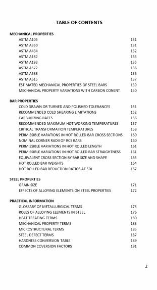
MECHANICAL PROPERTIES ASTM A105 131
ASTM A350 131
ASTM A434 132
ASTM A182 133
ASTM A193 135
ASTM A572 136
ASTM A588 136
ASTM A615 137
ESTIMATED MECHANICAL PROPERTIES OF STEEL BARS 139
MECHANICAL PROPERTY VARIATIONS WITH CARBON CONENT 150
BAR PROPERTIES COLD DRAWN OR TURNED AND POLISHED TOLERANCES 151
RECOMMENDED COLD SHEARING LIMITATIONS 152
CARBURIZING RATES 156
RECOMMENDED MAXIMUM HOT WORKING TEMPERATURES 157
CRITICAL TRANSFORMATION TEMPERATURES 158
PERMISSIBLE VARATIONS IN HOT ROLLED BAR CROSS SECTIONS 160
NOMINAL CORNER RADII OF RCS BARS 160
PERMISSIBLE VARIATIONS IN HOT ROLLED LENGTH 161
PERMISSIBLE VARIATIONS IN HOT ROLLED BAR STRAIGHTNESS 161
EQUIVALENT CROSS SECTION BY BAR SIZE AND SHAPE 163
HOT ROLLED BAR WEIGHTS 164
HOT ROLLED BAR REDUCTION RATIOS AT SDI 167
STEEL PROPERTIES GRAIN SIZE 171
EFFECTS OF ALLOYING ELEMENTS ON STEEL PROPERTIES 172
PRACTICAL INFORMATION GLOSSARY OF METALLURGICAL TERMS 175
ROLES OF ALLOYING ELEMENTS IN STEEL 176
HEAT TREATING TERMS 180
MECHANICAL PROPERTY TERMS 183
MICROSTRUCTURAL TERMS 185
STEEL DEFECT TERMS 187
HARDNESS CONVERSION TABLE 189
COMMON COVERSION FACTORS 191
3
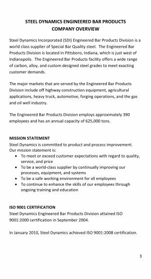
STEEL DYNAMICS ENGINEERED BAR PRODUCTS COMPANY OVERVIEW
Steel Dynamics Incorporated (SDI) Engineered Bar Products Division is a
world class supplier of Special Bar Quality steel. The Engineered Bar
Products Division is located in Pittsboro, Indiana, which is just west of
Indianapolis. The Engineered Bar Products facility offers a wide range
of carbon, alloy, and custom designed steel grades to meet exacting
customer demands.
The major markets that are served by the Engineered Bar Products
Division include off highway construction equipment, agricultural
applications, heavy truck, automotive, forging operations, and the gas
and oil well industry.
The Engineered Bar Products Division employs approximately 390
employees and has an annual capacity of 625,000 tons.
MISSION STATEMENT Steel Dynamics is committed to product and process improvement.
Our mission statement is:
x To meet or exceed customer expectations with regard to quality,
service, and price
x To be a world-class supplier by continually improving our
processes, equipment, and systems
x To be a safe working environment for all employees
x To continue to enhance the skills of our employees through
ongoing training and education
ISO 9001 CERTIFICATION
Steel Dynamics Engineered Bar Products Division attained ISO
9001:2000 certification in September 2004.
In January 2010, Steel Dynamics achieved ISO 9001:2008 certification.
4
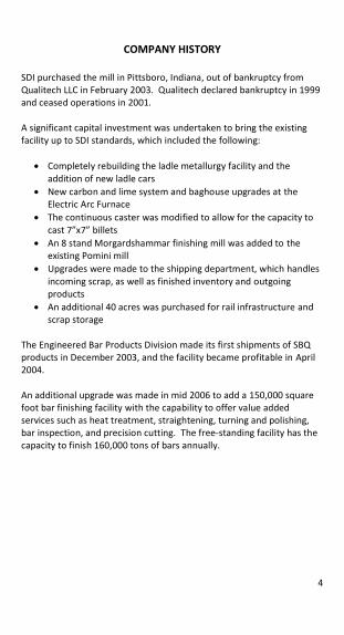
COMPANY HISTORY SDI purchased the mill in Pittsboro, Indiana, out of bankruptcy from
Qualitech LLC in February 2003. Qualitech declared bankruptcy in 1999
and ceased operations in 2001.
A significant capital investment was undertaken to bring the existing
facility up to SDI standards, which included the following:
x Completely rebuilding the ladle metallurgy facility and the
addition of new ladle cars
x New carbon and lime system and baghouse upgrades at the
Electric Arc Furnace
x The continuous caster was modified to allow for the capacity to
cast 7”x7” billets
x An 8 stand Morgardshammar finishing mill was added to the
existing Pomini mill
x Upgrades were made to the shipping department, which handles
incoming scrap, as well as finished inventory and outgoing
products
x An additional 40 acres was purchased for rail infrastructure and
scrap storage
The Engineered Bar Products Division made its first shipments of SBQ
products in December 2003, and the facility became profitable in April
2004.
An additional upgrade was made in mid 2006 to add a 150,000 square
foot bar finishing facility with the capability to offer value added
services such as heat treatment, straightening, turning and polishing,
bar inspection, and precision cutting. The free-standing facility has the
capacity to finish 160,000 tons of bars annually.
5
PRODUCTS AND SERVICES
SDI produces special bar quality (SBQ) and merchant bar quality (MBQ)
steel in rounds ranging in diameter from 1 to 9 inches and round
cornered squares (RCS) ranging in diameter from 2-1/2 to 8 inches. The
facility also has the ability to produce rebar in sizes 5 through 11. The
production and availability of rebar is based on market conditions.
SDI produces a wide range of carbon and low alloy steels, such as:
x Plain carbon steels (AISI series 10xx)
x Resulfurized carbon steels (AISI series 11xx)
x Rephosphorized and Resulfurized carbon steels (AISI series 12xx)
x High Manganese carbon steels (AISI series 13xx and 15xx)
x Cr Alloy Steels (AISI series 51xx and 52xx)
x Cr-Mo Alloy Steels (AISI series 41xx)
x Ni-Cr-Mo Alloy Steels (AISI Series 43xx, 47xx, 86xx, and 88xx)
x Vanadium micro-alloy steels (10V45, 11V41)
x Boron Treated Steels
x Structural Grades ASTM A36 and A572 Grade 50
x Low Alloy Tube and Flange Grades (T2/F2, T11/F11, T22/F22)
The grades listed above are a summary of those produced at the
Engineered Bar Products facility. Please inquire for grades not listed
above or for custom designed grades.
Hot-Rolled cut lengths are available between 16 and 40 feet. Steel
Dynamics can maintain all ASTM tolerances for diameter, length, and
straightness on all hot rolled products.
The Engineered Bar Products Rolling Mill metallurgical lab has the
capability to provide the full spectrum of metallurgical testing including
tensile, hardness, charpy impact, grain size, jominy, microcleanliness,
macrocleanliness, and aircraft quality testing.
6
The Engineered Bar Products Bar Finishing facility is equipped to
perform heat treating operations such as Quench and Temper,
Normalizing, and Annealing (LP, Spheroidize, Cold Shear, Stress
Relieve). In addition to heat treating, the Bar Finishing facility can
provide additional services such as:
x Straightening
x Turning and Polishing
x Cutting to Length
x Shot Blasting
x Non Destructive Testing
The Bar Finishing Metallurgical Lab at Steel Dynamics has the capability
to provide metallurgical testing such as tensile, hardness, and charpy
impact following heat treatment. The lab is also equipped with a
scanning electron microscope that is used for research and product
evaluation purposes.
7
PROCESS DESCRIPTION AND CAPABILITIES
MELTING AND CASTING
SDI is equipped with one Electric Arc Furnace (EAF). The EAF is charged
with approximately 115 tons of primarily scrap metal in order to yield
an aim tapped heat size of 100 tons. Heats are killed following tap with
a Silicon-Manganese addition.
Following tap, heats are treated at a Ladle Metallurgy Facility (LMF). At
the LMF, slag additions and modifiers are used to work the slag and
trap inclusions. Alloy additions are made at the LMF, as well as re-
heating the steel for further processing or shipment to the caster.
Heats that require degas treatment have the slag layer removed by
means of a mechanical rake. These heats are then treated at the
Vacuum Tank Degasser (VTD). Typical gas levels following VTD
treatment are 2 ppm H2, 80 ppm N2, and 20 ppm O2.
The continuous caster is a three strand, vertical curved radius machine.
Each strand is equipped with automatic mould level control and
electromagnetic stirring. Five withdrawal straightener units are used to
straighten the strands and also apply soft reduction. The dimensions of
the semi-finished bloom are 10.3 x 14.1 inches.
ROLLING
The rolling mill is equipped with a walking beam furnace with a capacity
of 125 tons per hour. Blooms are de-scaled after exiting the furnace,
and then proceed through a five stand roughing mill, a six stand
intermediate mill, and an eight stand finishing mill. Dimensional control
is maintained by optical laser gauges and manual micrometer checks.
Bars are sheared after reaching their final dimension onto a 125 feet
long walking beam cooling bed. Bars are then trimmed to the specified
cut length and bundled together for shipment.
8
HEAT TREATING
The Bar Finishing facility is equipped with five Sauder Energy Car
Bottom furnaces. There is one high temperature furnace capable of
reaching 2100°F, while the others are capable of reaching 1800°F. The
furnaces are limited to a maximum bar length of 33 feet. The quench
tank has a 30,000 gallon capacity and is capable of providing agitation
and temperature control. Water is the only quench media used at the
Bar Finishing facility. The minimum bar diameter that can be quenched
is 2.5 inches.
BAR INSPECTION
There are two inspection lines at the Bar Finishing facility, a small bar
inspection line (SBIL) and a large bar inspection line (LBIL). The SBIL can
accommodate round bars ranging in diameter from one to five inches
while the LBIL can accommodate round bars from 2.5 to 9 inches and
round cornered squares from 2.5 to 8 inches. Both lines can
accommodate bar lengths of 15 to 45 feet.
At the SBIL, bars are rotary straightened and chamfered prior to
inspection. Surface inspection is performed via a Forester Magnetic
Flux Leakage unit, capable of 100% surface coverage with seam
detection of 0.3 mm for smaller bars and 0.5 mm for larger bars.
Ultrasonic inspection is performed via a rotary immersion UT inspection
unit, capable of 100% volumetric coverage using normal incidence and
shear waves. Ultrasonic inspection is capable of detecting 1mm wide
defects. The SBIL is also equipped with a 100% Eddy Current grade
verification coil.
On the LBIL, bars are shot blasted and pass through an Eddy Current
grade verification coil. Surface inspection is performed via an Eddy
Current surface inspection unit, capable of 100% surface coverage with
seam detection of 0.5mm. Ultrasonic inspection is performed via a
Magnetic Analysis Corp 48 channel transducer with four fixed heads,
capable of 100% volumetric coverage. Ultrasonic inspection is capable
of detecting 1mm wide defects.
9
TURNING AND POLISHING
The turning line has a capacity of 1.031 inch to 4.25 inch incoming
diameter, and is capable of meeting ASTM A108 tolerances. The line
can accommodate bar lengths ranging from 14 to 25 feet. The line is
equipped with bar chamfering, facing, and etching capabilities. The
straightener/polisher is capable of attaining greater than 25Ra surface
finish. The turning line is equipped with an Eddy Current tester for
surface inspection.
STRAIGHTENING
The bar finishing facility has a Bronx Nine Roll straightener and a #5
Medart Two Roll straightener. The units are capable of meeting both
standard and special straightness tolerances as listed in ASTM A29.
MULT CUT-TO-LENGTH SAWING
Cut-to-length sawing is accomplished with two Nishijimax Precision
Carbide Rotary Saws, with a capacity of 1.00 to 5.9 inch rounds. The
saws can produce cut lengths from 0.5 to 118 inches, with a standard
length tolerance of +/- 0.010” or 0.25 mm.
A Hem High Speed Double Column band saw line is also available. It has
a capacity of 4 to 25 inch rounds as well as being able to cut bundles.
Cut lengths are available from 5 to 24 feet, with a tolerance of -0/+0.25
inches.

10
NOTES
11
MAJOR STEEL GROUPS
Carbon Steel Carbon steel usually contains up to 1.65% manganese, and contains no
other added elements to provide any specific alloying effects, except for
deoxidation or grain size control. Carbon steels are often classified
according to carbon concentration, i.e. low, medium, and high carbon
steels. The term ‘plain carbon steel’ is often used to describe steels
which only contain residual concentrations of impurities other than
carbon and manganese.
The greatest quantity of steel produced falls into the low-carbon
classification, and is typically less than 0.25% carbon. Low-carbon steels
are typically unresponsive to heat treatments intended to form
martensite and strengthening is usually accomplished through cold
working. Low-carbon steels are relatively soft and weak but have
excellent ductility and toughness.
Medium-carbon steels have carbon concentrations typically between
0.25% and 0.60%, and may be heat treated by austenitizing, quenching,
and tempering to improve their mechanical properties. Medium-
carbon steels are stronger than low-carbon steels, but with a reduction
in ductility and toughness. High-carbon steels have carbon
concentrations typically between 0.60% and 1.4%, and are the hardest
and strongest of the carbon steels, but with the least amount of
ductility.
Microalloy Steel Microalloy steels, or High Strength Low Alloy (HSLA) steels, are a group
of low-carbon steels which contain a small but deliberate addition of
one or more alloying elements such as: vanadium, columbium, and
titanium. These steels have increased strength, combined with good
ductility in the hot rolled condition. These properties are achieved by a
combination of fine grain size and precipitation of finely dispersed
particles throughout the steel’s microstructure. Some HSLA steels have improved atmospheric corrosion.
Alloy Steel Steel containing significant quantities of one or more alloying elements
(other than carbon and the commonly accepted amounts of
manganese, and silicon) added to make changes in mechanical or
physical properties. Common alloying elements include nickel,
chromium, and molybdenum, among others.
12
AISI-SAE GRADE DESIGNATIONS The most widely used system for designating carbon and alloy steels
was developed by the American Iron and Steel Institute (AISI) and the
Society of Automotive Engineers (SAE). In this system, a particular
designation implies the same limits and ranges of chemical composition
for both an AISI steel and the corresponding SAE steel. Any differences
between AISI and SAE grade designations or limits of chemical
composition are unintentional. The fact that a particular steel grade is
listed by AISI or SAE implies only that it has been produced in
appreciable quantity. It does not imply that other grades are
unavailable, nor does it imply that any particular steel producer makes
all of the listed grades. All compositions are expressed as weight
percents. The SAE designations are published in the annual SAE
handbook under various SAE standards. These standards are comprised
entirely of listings of SAE designations and the limits and ranges of
chemical composition defined by these designations.
UNS DESIGNATIONS The Unified Numbering System (UNS) has been developed by the AISI,
SAE, and several other technical societies, trade associations, and
United States government agencies. A UNS number, which is a
designation of a chemical composition and not a specification, is
assigned to each chemical composition of a metallic alloy. Existing
systems of designations, including the AISI-SAE system for steels, have
been incorporated into the UNS designations.
The UNS designation of a metallic alloy consists of a letter and five
numerals. The letters indicate the broad class of alloys, and the
numerals define specific alloys and modifications within each class. For
practical purposes, carbon and alloy steel bars begin with the letters G
or H, the latter describing H-band steels. The first four numerals usually
describe the AISI-SAE steel grade designation. The last numeral is
typically a zero, unless the steel is modified as follows: a 1 in the last
digit signifies boron; a 4 in the last digit signifies lead; a 6 in the last digit
indicates Electric Furnace practice with reduced levels of phosphorus
and sulfur. The Unified Numbering System is described in greater detail
in the latest editions of SAE J1086 and ASTM E 527. The grades in this
13
manual will be described with the standard AISI-SAE designation
instead of the UNS designation.
Certain elements are present in small quantities in most steels. They
are not intentionally added, but exist in the steel due to the raw
materials used during production. These elements are considered
residual or incidental as long as they do not exceed specified maximum
limits. The common residual elements of concern are Cu, Ni, Cr, and
Mo, with common accepted maximum limits of: 0.35% Cu, 0.25% Ni,
0.20% Cr, and 0.06% Mo according to SAE and ASTM standards. All
standard grades listed are subject to these residual maximum limits
unless otherwise noted. Any differences in the maximum residual limits
must be agreed upon by purchaser and supplier.
14
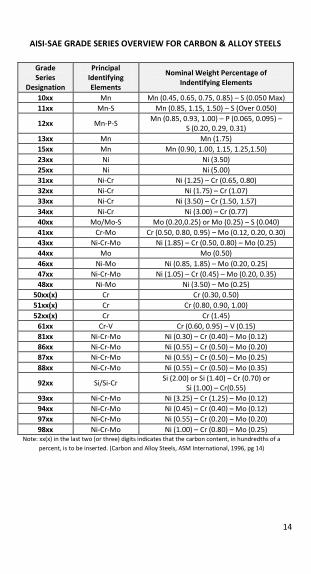
AISI-SAE GRADE SERIES OVERVIEW FOR CARBON & ALLOY STEELS
Grade Series
Designation
Principal Identifying Elements
Nominal Weight Percentage of Indentifying Elements
10xx Mn Mn (0.45, 0.65, 0.75, 0.85) – S (0.050 Max)
11xx Mn-S Mn (0.85, 1.15, 1.50) – S (Over 0.050)
12xx Mn-P-S Mn (0.85, 0.93, 1.00) – P (0.065, 0.095) –
S (0.20, 0.29, 0.31)
13xx Mn Mn (1.75)
15xx Mn Mn (0.90, 1.00, 1.15, 1.25,1.50)
23xx Ni Ni (3.50)
25xx Ni Ni (5.00)
31xx Ni-Cr Ni (1.25) – Cr (0.65, 0.80)
32xx Ni-Cr Ni (1.75) – Cr (1.07)
33xx Ni-Cr Ni (3.50) – Cr (1.50, 1.57)
34xx Ni-Cr Ni (3.00) – Cr (0.77)
40xx Mo/Mo-S Mo (0.20,0.25) or Mo (0.25) – S (0.040)
41xx Cr-Mo Cr (0.50, 0.80, 0.95) – Mo (0.12, 0.20, 0.30)
43xx Ni-Cr-Mo Ni (1.85) – Cr (0.50, 0.80) – Mo (0.25)
44xx Mo Mo (0.50)
46xx Ni-Mo Ni (0.85, 1.85) – Mo (0.20, 0.25)
47xx Ni-Cr-Mo Ni (1.05) – Cr (0.45) – Mo (0.20, 0.35)
48xx Ni-Mo Ni (3.50) – Mo (0.25)
50xx(x) Cr Cr (0.30, 0.50)
51xx(x) Cr Cr (0.80, 0.90, 1.00)
52xx(x) Cr Cr (1.45)
61xx Cr-V Cr (0.60, 0.95) – V (0.15)
81xx Ni-Cr-Mo Ni (0.30) – Cr (0.40) – Mo (0.12)
86xx Ni-Cr-Mo Ni (0.55) – Cr (0.50) – Mo (0.20)
87xx Ni-Cr-Mo Ni (0.55) – Cr (0.50) – Mo (0.25)
88xx Ni-Cr-Mo Ni (0.55) – Cr (0.50) – Mo (0.35)
92xx Si/Si-Cr Si (2.00) or Si (1.40) – Cr (0.70) or
Si (1.00) – Cr(0.55)
93xx Ni-Cr-Mo Ni (3.25) – Cr (1.25) – Mo (0.12)
94xx Ni-Cr-Mo Ni (0.45) – Cr (0.40) – Mo (0.12)
97xx Ni-Cr-Mo Ni (0.55) – Cr (0.20) – Mo (0.20)
98xx Ni-Cr-Mo Ni (1.00) – Cr (0.80) – Mo (0.25) Note: xx(x) in the last two (or three) digits indicates that the carbon content, in hundredths of a
percent, is to be inserted. (Carbon and Alloy Steels, ASM International, 1996, pg 14)
15
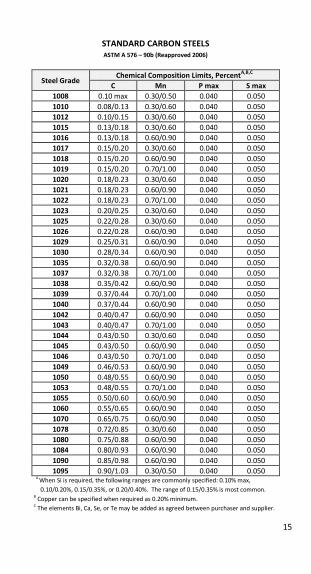
STANDARD CARBON STEELS ASTM A 576 – 90b (Reapproved 2006)
Steel Grade Chemical Composition Limits, PercentA,B,C
C Mn P max S max
1008 0.10 max 0.30/0.50 0.040 0.050
1010 0.08/0.13 0.30/0.60 0.040 0.050
1012 0.10/0.15 0.30/0.60 0.040 0.050
1015 0.13/0.18 0.30/0.60 0.040 0.050
1016 0.13/0.18 0.60/0.90 0.040 0.050
1017 0.15/0.20 0.30/0.60 0.040 0.050
1018 0.15/0.20 0.60/0.90 0.040 0.050
1019 0.15/0.20 0.70/1.00 0.040 0.050
1020 0.18/0.23 0.30/0.60 0.040 0.050
1021 0.18/0.23 0.60/0.90 0.040 0.050
1022 0.18/0.23 0.70/1.00 0.040 0.050
1023 0.20/0.25 0.30/0.60 0.040 0.050
1025 0.22/0.28 0.30/0.60 0.040 0.050
1026 0.22/0.28 0.60/0.90 0.040 0.050
1029 0.25/0.31 0.60/0.90 0.040 0.050
1030 0.28/0.34 0.60/0.90 0.040 0.050
1035 0.32/0.38 0.60/0.90 0.040 0.050
1037 0.32/0.38 0.70/1.00 0.040 0.050
1038 0.35/0.42 0.60/0.90 0.040 0.050
1039 0.37/0.44 0.70/1.00 0.040 0.050
1040 0.37/0.44 0.60/0.90 0.040 0.050
1042 0.40/0.47 0.60/0.90 0.040 0.050
1043 0.40/0.47 0.70/1.00 0.040 0.050
1044 0.43/0.50 0.30/0.60 0.040 0.050
1045 0.43/0.50 0.60/0.90 0.040 0.050
1046 0.43/0.50 0.70/1.00 0.040 0.050
1049 0.46/0.53 0.60/0.90 0.040 0.050
1050 0.48/0.55 0.60/0.90 0.040 0.050
1053 0.48/0.55 0.70/1.00 0.040 0.050
1055 0.50/0.60 0.60/0.90 0.040 0.050
1060 0.55/0.65 0.60/0.90 0.040 0.050
1070 0.65/0.75 0.60/0.90 0.040 0.050
1078 0.72/0.85 0.30/0.60 0.040 0.050
1080 0.75/0.88 0.60/0.90 0.040 0.050
1084 0.80/0.93 0.60/0.90 0.040 0.050
1090 0.85/0.98 0.60/0.90 0.040 0.050
1095 0.90/1.03 0.30/0.50 0.040 0.050 A
When Si is required, the following ranges are commonly specified: 0.10% max,
0.10/0.20%, 0.15/0.35%, or 0.20/0.40%. The range of 0.15/0.35% is most common. B
Copper can be specified when required as 0.20% minimum. C
The elements Bi, Ca, Se, or Te may be added as agreed between purchaser and supplier.
16
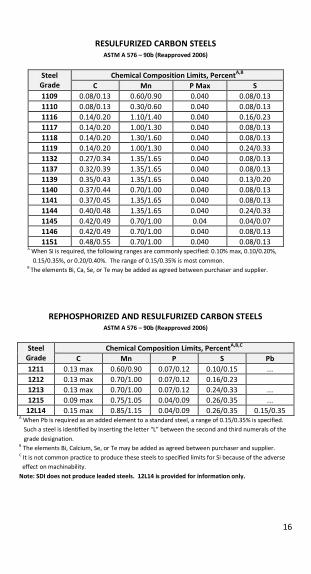
RESULFURIZED CARBON STEELS
ASTM A 576 – 90b (Reapproved 2006)
Steel Grade
Chemical Composition Limits, PercentA,B
C Mn P Max S 1109 0.08/0.13 0.60/0.90 0.040 0.08/0.13
1110 0.08/0.13 0.30/0.60 0.040 0.08/0.13
1116 0.14/0.20 1.10/1.40 0.040 0.16/0.23
1117 0.14/0.20 1.00/1.30 0.040 0.08/0.13
1118 0.14/0.20 1.30/1.60 0.040 0.08/0.13
1119 0.14/0.20 1.00/1.30 0.040 0.24/0.33
1132 0.27/0.34 1.35/1.65 0.040 0.08/0.13
1137 0.32/0.39 1.35/1.65 0.040 0.08/0.13
1139 0.35/0.43 1.35/1.65 0.040 0.13/0.20
1140 0.37/0.44 0.70/1.00 0.040 0.08/0.13
1141 0.37/0.45 1.35/1.65 0.040 0.08/0.13
1144 0.40/0.48 1.35/1.65 0.040 0.24/0.33
1145 0.42/0.49 0.70/1.00 0.04 0.04/0.07
1146 0.42/0.49 0.70/1.00 0.040 0.08/0.13
1151 0.48/0.55 0.70/1.00 0.040 0.08/0.13 A
When Si is required, the following ranges are commonly specified: 0.10% max, 0.10/0.20%,
0.15/0.35%, or 0.20/0.40%. The range of 0.15/0.35% is most common. B
The elements Bi, Ca, Se, or Te may be added as agreed between purchaser and supplier.
REPHOSPHORIZED AND RESULFURIZED CARBON STEELS
ASTM A 576 – 90b (Reapproved 2006)
Steel Grade
Chemical Composition Limits, PercentA,B,C
C Mn P S Pb 1211 0.13 max 0.60/0.90 0.07/0.12 0.10/0.15 ...
1212 0.13 max 0.70/1.00 0.07/0.12 0.16/0.23
1213 0.13 max 0.70/1.00 0.07/0.12 0.24/0.33 ...
1215 0.09 max 0.75/1.05 0.04/0.09 0.26/0.35 ...
12L14 0.15 max 0.85/1.15 0.04/0.09 0.26/0.35 0.15/0.35 A When Pb is required as an added element to a standard steel, a range of 0.15/0.35% is specified.
Such a steel is identified by inserting the letter “L” between the second and third numerals of the
grade designation. B The elements Bi, Calcium, Se, or Te may be added as agreed between purchaser and supplier.
C It is not common practice to produce these steels to specified limits for Si because of the adverse
effect on machinability.
Note: SDI does not produce leaded steels. 12L14 is provided for information only.
17
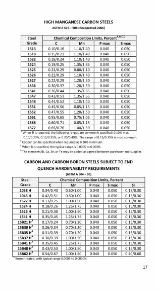
HIGH MANGANESE CARBON STEELS ASTM A 576 – 90b (Reapproved 2006)
Steel Grade
Chemical Composition Limits, PercentA,B,C,D
C Mn P max S max 1513 0.10/0.16 1.10/1.40 0.040 0.050
1518 0.15/0.21 1.10/1.40 0.040 0.050
1522 0.18/0.24 1.10/1.40 0.040 0.050
1524 0.19/0.25 1.35/1.65 0.040 0.050
1525 0.23/0.29 0.80/1.10 0.040 0.050
1526 0.22/0.29 1.10/1.40 0.040 0.050
1527 0.22/0.29 1.20/1.50 0.040 0.050
1536 0.30/0.37 1.20/1.50 0.040 0.050
1541 0.36/0.44 1.35/1.65 0.040 0.050
1547 0.43/0.51 1.35/1.65 0.040 0.050
1548 0.44/0.52 1.10/1.40 0.040 0.050
1551 0.45/0.56 0.85/1.15 0.040 0.050
1552 0.47/0.55 1.20/1.50 0.040 0.050
1561 0.55/0.65 0.75/1.05 0.040 0.050
1566 0.60/0.71 0.85/1.15 0.040 0.050
1572 0.65/0.76 1.00/1.30 0.040 0.050
A When Si is required, the following ranges are commonly specified: 0.10% max,
0.10/0.20%, 0.15/0.35%, or 0.20/0.40%. The range of 0.15/0.35% is most common. B
Copper can be specified when required as 0.20% minimum. C
When B is specified, the typical range is 0.0005 to 0.003%. D
The elements Bi, Ca, Se, or Te may be added as agreed between purchaser and supplier.
CARBON AND CARBON BORON STEELS SUBJECT TO END QUENCH HARDENABILITY REQUIREMENTS
(ASTM A 304 – 05)
Steel Grade
Chemical Composition Limits, Percent C Mn P max S max Si
1038 H 0.34/0.43 0.50/1.00 0.040 0.050 0.15/0.30
1045 H 0.42/0.51 0.50/1.00 0.040 0.050 0.15/0.30
1522 H 0.17/0.25 1.00/1.50 0.040 0.050 0.15/0.30
1524 H 0.18/0.26 1.25/1.75 0.040 0.050 0.15/0.30
1526 H 0.21/0.30 1.00/1.50 0.040 0.050 0.15/0.30
1541 H 0.35/0.45 1.25/1.75 0.040 0.050 0.15/0.30
15B21 HA 0.17/0.24 0.70/1.20 0.040 0.050 0.15/0.30
15B30 HA 0.26/0.34 0.70/1.20 0.040 0.050 0.15/0.30
15B35 HA 0.31/0.39 0.70/1.20 0.040 0.050 0.15/0.30
15B37 HA 0.30/0.39 1.00/1.50 0.040 0.050 0.15/0.30
15B41 HA 0.35/0.45 1.25/1.75 0.040 0.050 0.15/0.30
15B48 HA 0.43/0.53 1.00/1.50 0.040 0.050 0.15/0.30
15B62 HA 0.54/0.67 1.00/1.50 0.040 0.050 0.40/0.60
A Boron treated, with typical range 0.0005 to 0.0030%.
18
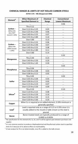
CHEMCAL RANGES & LIMITS OF HOT ROLLED CARBON STEELS ASTM A 576 – 90b (Reapproved 2006)
ElementA When Maximum of Specified Element is:
Chemical Range
Conventional Lowest Maximum
Carbon – (When Mn does NOT
exceed 1.10%)
... ... 0.06
Thru 0.12 ... ...
Over 0.12 thru 0.25 0.05 ...
Over 0.25 thru 0.40 0.06 ...
Over 0.40 thru 0.55 0.07 ...
Over 0.55 thru 0.80 0.10 ...
Over 0.80 0.13 ...
Carbon – (When Mn
DOES exceed
1.10%)
Over 0.12 thru 0.25 0.06 ...
Over 0.25 thru 0.40 0.07 ...
Over 0.40 thru 0.55 0.08 ...
Over 0.55 thru 0.80 0.11 ...
Over 0.80 0.14 ...
Manganese
... ... 0.35
Thru 0.40 0.15 ...
Over 0.40 thru 0.50 0.20 ...
Over 0.50 thru 1.65 0.30 ...
Phosphorus
... ... 0.03
Thru 0.04 ... ...
Over 0.04 thru 0.08 0.03 ...
Over 0.08 thru 0.13 0.05 ...
Sulfur
Thru 0.05 ... 0.05
Over 0.05 thru 0.09 0.03 ...
Over 0.09 thru 0.15 0.05 ...
Over 0.15 thru 0.23 0.07 ...
Over 0.23 thru 0.50 0.09 ...
SiliconB
Thru 0.10 ... 0.10
Over 0.10 thru 0.15 0.08 ...
Over 0.15 thru 0.20 0.10 ...
Over 0.20 thru 0.30 0.15 ...
Over 0.30 thru 0.60 0.20 ...
Copper When Cu is required as an added element, 0.20% minimum is
generally specified
LeadC Lead is reported only as a range of 0.15 to 0.35% since it is
usually added to the mould or ladle stream as the steel is
poured
Boron Boron treated steels are typically produced to a range of
0.0005 to 0.003% A
The specification for the elements Bi, Ca, Se, and Te will be agreed upon between purchaser and
supplier. B
It is not common practice to produce a Rephosphorized and Resulfurized carbon steel to specified
limits for Si because of its adverse effect on machinability. C
A heat analysis for Pb is not determinable, since Pb is added to the ladle stream.
19
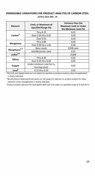
PERMISSIBLE VARIATIONS FOR PRODUCT ANALYSIS OF CARBON STEEL ASTM A 29/A 29M – 05
Element Limit, or Maximum of Specified Range (%)
Variance Over the Maximum Limit or Under
the Minimum Limit (%)
CarbonA Thru 0.25 0.02
Over 0.25 thru 0.55 0.03
Over 0.55 0.04
Manganese Thru 0.90 0.03
Over 0.90 thru 1.65 0.06
PhosphorusA,B Basic steels 0.008 over
Acid Bessemer steel 0.01
SulfurA,B 0.008
Silicon Thru 0.35 0.02
Over 0.35 thru 0.60 0.05
Copper Under minimum only for Cu
bearing steels 0.02
LeadC 0.15 thru 0.35 0.03 A
Rimmed and capped steels are not subject to rejection on product analysis unless misapplication
is clearly indicated.
B Resulfurized or Rephosphorized steels are not subject to rejection on product analysis for these
elements unless misapplication is clearly indicated.
C
Product analysis tolerance for lead applies both over and under to a specified range of 0.15/0.35 %.
20
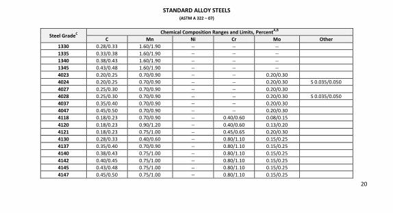
STANDARD ALLOY STEELS
(ASTM A 322 – 07)
Steel GradeC Chemical Composition Ranges and Limits, PercentA,B
C Mn Ni Cr Mo Other 1330 0.28/0.33 1.60/1.90 -- -- --
1335 0.33/0.38 1.60/1.90 -- -- --
1340 0.38/0.43 1.60/1.90 -- -- --
1345 0.43/0.48 1.60/1.90 -- -- --
4023 0.20/0.25 0.70/0.90 -- -- 0.20/0.30
4024 0.20/0.25 0.70/0.90 -- -- 0.20/0.30 S 0.035/0.050
4027 0.25/0.30 0.70/0.90 -- -- 0.20/0.30
4028 0.25/0.30 0.70/0.90 -- -- 0.20/0.30 S 0.035/0.050
4037 0.35/0.40 0.70/0.90 -- -- 0.20/0.30
4047 0.45/0.50 0.70/0.90 -- -- 0.20/0.30
4118 0.18/0.23 0.70/0.90 -- 0.40/0.60 0.08/0.15
4120 0.18/0.23 0.90/1.20 -- 0.40/0.60 0.13/0.20
4121 0.18/0.23 0.75/1.00 -- 0.45/0.65 0.20/0.30
4130 0.28/0.33 0.40/0.60 -- 0.80/1.10 0.15/0.25
4137 0.35/0.40 0.70/0.90 -- 0.80/1.10 0.15/0.25
4140 0.38/0.43 0.75/1.00 -- 0.80/1.10 0.15/0.25
4142 0.40/0.45 0.75/1.00 -- 0.80/1.10 0.15/0.25
4145 0.43/0.48 0.75/1.00 -- 0.80/1.10 0.15/0.25
4147 0.45/0.50 0.75/1.00 -- 0.80/1.10 0.15/0.25
21
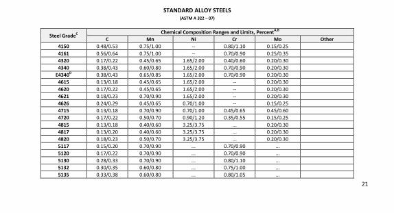
STANDARD ALLOY STEELS
(ASTM A 322 – 07)
Steel GradeC Chemical Composition Ranges and Limits, PercentA,B
C Mn Ni Cr Mo Other 4150 0.48/0.53 0.75/1.00 -- 0.80/1.10 0.15/0.25
4161 0.56/0.64 0.75/1.00 -- 0.70/0.90 0.25/0.35
4320 0.17/0.22 0.45/0.65 1.65/2.00 0.40/0.60 0.20/0.30
4340 0.38/0.43 0.60/0.80 1.65/2.00 0.70/0.90 0.20/0.30
E4340D 0.38/0.43 0.65/0.85 1.65/2.00 0.70/0.90 0.20/0.30
4615 0.13/0.18 0.45/0.65 1.65/2.00 -- 0.20/0.30
4620 0.17/0.22 0.45/0.65 1.65/2.00 -- 0.20/0.30
4621 0.18/0.23 0.70/0.90 1.65/2.00 -- 0.20/0.30
4626 0.24/0.29 0.45/0.65 0.70/1.00 -- 0.15/0.25
4715 0.13/0.18 0.70/0.90 0.70/1.00 0.45/0.65 0.45/0.60
4720 0.17/0.22 0.50/0.70 0.90/1.20 0.35/0.55 0.15/0.25
4815 0.13/0.18 0.40/0.60 3.25/3.75 ... 0.20/0.30
4817 0.13/0.20 0.40/0.60 3.25/3.75 ... 0.20/0.30
4820 0.18/0.23 0.50/0.70 3.25/3.75 ... 0.20/0.30
5117 0.15/0.20 0.70/0.90 ... 0.70/0.90 ...
5120 0.17/0.22 0.70/0.90 ... 0.70/0.90 ...
5130 0.28/0.33 0.70/0.90 ... 0.80/1.10 ...
5132 0.30/0.35 0.60/0.80 ... 0.75/1.00 ...
5135 0.33/0.38 0.60/0.80 ... 0.80/1.05 ...
22
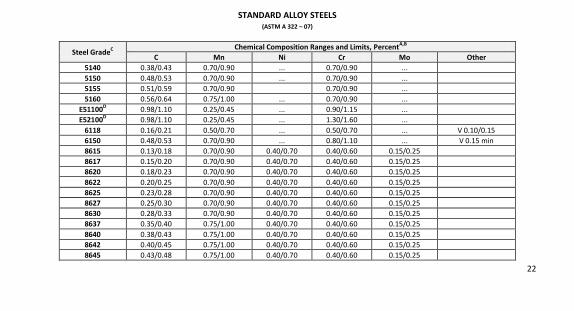
STANDARD ALLOY STEELS
(ASTM A 322 – 07)
Steel GradeC Chemical Composition Ranges and Limits, PercentA,B
C Mn Ni Cr Mo Other 5140 0.38/0.43 0.70/0.90 ... 0.70/0.90 ...
5150 0.48/0.53 0.70/0.90 ... 0.70/0.90 ...
5155 0.51/0.59 0.70/0.90 0.70/0.90 ...
5160 0.56/0.64 0.75/1.00 ... 0.70/0.90 ...
E51100D 0.98/1.10 0.25/0.45 ... 0.90/1.15 ...
E52100D 0.98/1.10 0.25/0.45 ... 1.30/1.60 ...
6118 0.16/0.21 0.50/0.70 ... 0.50/0.70 ... V 0.10/0.15
6150 0.48/0.53 0.70/0.90 ... 0.80/1.10 ... V 0.15 min
8615 0.13/0.18 0.70/0.90 0.40/0.70 0.40/0.60 0.15/0.25
8617 0.15/0.20 0.70/0.90 0.40/0.70 0.40/0.60 0.15/0.25
8620 0.18/0.23 0.70/0.90 0.40/0.70 0.40/0.60 0.15/0.25
8622 0.20/0.25 0.70/0.90 0.40/0.70 0.40/0.60 0.15/0.25
8625 0.23/0.28 0.70/0.90 0.40/0.70 0.40/0.60 0.15/0.25
8627 0.25/0.30 0.70/0.90 0.40/0.70 0.40/0.60 0.15/0.25
8630 0.28/0.33 0.70/0.90 0.40/0.70 0.40/0.60 0.15/0.25
8637 0.35/0.40 0.75/1.00 0.40/0.70 0.40/0.60 0.15/0.25
8640 0.38/0.43 0.75/1.00 0.40/0.70 0.40/0.60 0.15/0.25
8642 0.40/0.45 0.75/1.00 0.40/0.70 0.40/0.60 0.15/0.25
8645 0.43/0.48 0.75/1.00 0.40/0.70 0.40/0.60 0.15/0.25
23
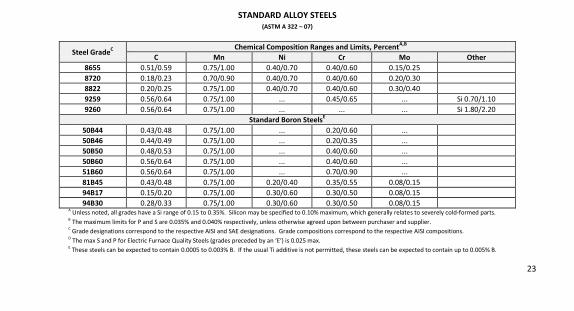
STANDARD ALLOY STEELS
(ASTM A 322 – 07)
Steel GradeC Chemical Composition Ranges and Limits, PercentA,B
C Mn Ni Cr Mo Other 8655 0.51/0.59 0.75/1.00 0.40/0.70 0.40/0.60 0.15/0.25
8720 0.18/0.23 0.70/0.90 0.40/0.70 0.40/0.60 0.20/0.30
8822 0.20/0.25 0.75/1.00 0.40/0.70 0.40/0.60 0.30/0.40
9259 0.56/0.64 0.75/1.00 ... 0.45/0.65 ... Si 0.70/1.10
9260 0.56/0.64 0.75/1.00 ... ... ... Si 1.80/2.20
Standard Boron SteelsE
50B44 0.43/0.48 0.75/1.00 ... 0.20/0.60 ...
50B46 0.44/0.49 0.75/1.00 ... 0.20/0.35 ...
50B50 0.48/0.53 0.75/1.00 ... 0.40/0.60 ...
50B60 0.56/0.64 0.75/1.00 ... 0.40/0.60 ...
51B60 0.56/0.64 0.75/1.00 ... 0.70/0.90 ...
81B45 0.43/0.48 0.75/1.00 0.20/0.40 0.35/0.55 0.08/0.15
94B17 0.15/0.20 0.75/1.00 0.30/0.60 0.30/0.50 0.08/0.15
94B30 0.28/0.33 0.75/1.00 0.30/0.60 0.30/0.50 0.08/0.15 A
Unless noted, all grades have a Si range of 0.15 to 0.35%. Silicon may be specified to 0.10% maximum, which generally relates to severely cold-formed parts.
B The maximum limits for P and S are 0.035% and 0.040% respectively, unless otherwise agreed upon between purchaser and supplier.
C Grade designations correspond to the respective AISI and SAE designations. Grade compositions correspond to the respective AISI compositions.
D The max S and P for Electric Furnace Quality Steels (grades preceded by an ‘E’) is 0.025 max.
E These steels can be expected to contain 0.0005 to 0.003% B. If the usual Ti additive is not permitted, these steels can be expected to contain up to 0.005% B.
24
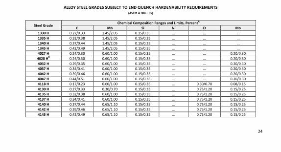
ALLOY STEEL GRADES SUBJECT TO END QUENCH HARDENABILITY REQUIREMENTS (ASTM A 304 – 05)
Steel Grade Chemical Composition Ranges and Limits, PercentA
C Mn Si Ni Cr Mo 1330 H 0.27/0.33 1.45/2.05 0.15/0.35 ... ... ...
1335 H 0.32/0.38 1.45/2.05 0.15/0.35 ... ... ...
1340 H 0.37/0.44 1.45/2.05 0.15/0.35 ... ... ...
1345 H 0.42/0.49 1.45/2.05 0.15/0.35 ... ... ...
4027 H 0.24/0.30 0.60/1.00 0.15/0.35 ... ... 0.20/0.30
4028 HB 0.24/0.30 0.60/1.00 0.15/0.35 ... ... 0.20/0.30
4032 H 0.29/0.35 0.60/1.00 0.15/0.35 ... ... 0.20/0.30
4037 H 0.34/0.41 0.60/1.00 0.15/0.35 ... ... 0.20/0.30
4042 H 0.39/0.46 0.60/1.00 0.15/0.35 ... ... 0.20/0.30
4047 H 0.44/0.51 0.60/1.00 0.15/0.35 ... ... 0.20/0.30
4118 H 0.17/0.23 0.60/1.00 0.15/0.35 ... 0.30/0.70 0.08/0.15
4130 H 0.27/0.33 0.30/0.70 0.15/0.35 ... 0.75/1.20 0.15/0.25
4135 H 0.32/0.38 0.60/1.00 0.15/0.35 ... 0.75/1.20 0.15/0.25
4137 H 0.34/0.41 0.60/1.00 0.15/0.35 ... 0.75/1.20 0.15/0.25
4140 H 0.37/0.44 0.65/1.10 0.15/0.35 ... 0.75/1.20 0.15/0.25
4142 H 0.39/0.46 0.65/1.10 0.15/0.35 ... 0.75/1.20 0.15/0.25
4145 H 0.42/0.49 0.65/1.10 0.15/0.35 ... 0.75/1.20 0.15/0.25
25
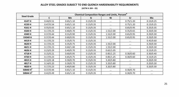
ALLOY STEEL GRADES SUBJECT TO END QUENCH HARDENABILITY REQUIREMENTS (ASTM A 304 – 05)
Steel Grade Chemical Composition Ranges and Limits, PercentA
C Mn Si Ni Cr Mo 4147 H 0.44/0.51 0.65/1.10 0.15/0.35 ... 0.75/1.20 0.15/0.25
4150 H 0.47/0.54 0.65/1.10 0.15/0.35 ... 0.75/1.20 0.15/0.25
4161 H 0.55/0.65 0.65/1.10 0.15/0.35 ... 0.65/0.95 0.25/0.35
4320 H 0.17/0.23 0.40/0.70 0.15/0.35 1.55/2.00 0.35/0.65 0.20/0.30
4340 H 0.37/0.44 0.55/0.90 0.15/0.35 1.55/2.00 0.65/0.95 0.20/0.30
E4340 H 0.37/0.44 0.60/0.95 0.15/0.35 1.55/2.00 0.65/0.95 0.20/0.30
4419 H 0.17/0.23 0.35/0.75 0.15/0.35 ... ... 0.45/0.60
4620 H 0.17/0.23 0.35/0.75 0.15/0.35 1.55/2.00 ... 0.20/0.30
4621 H 0.17/0.23 0.60/1.00 0.15/0.35 1.55/2.00 ... 0.20/0.30
4626 H 0.23/0.29 0.40/0.70 0.15/0.35 0.65/1.05 ... 0.15/0.25
4718 H 0.15/0.21 0.60/0.95 0.15/0.35 0.85/1.25 0.30/0.60 0.30/0.40
4720 H 0.17/0.23 0.45/0.75 0.15/0.35 0.85/1.25 0.30/0.60 0.15/0.25
4815 H 0.12/0.18 0.30/0.70 0.15/0.35 3.20/3.80 ... 0.20/0.30
4817 H 0.14/0.20 0.30/0.70 0.15/0.35 3.20/3.80 ... 0.20/0.30
4820 H 0.17/0.23 0.40/0.80 0.15/0.35 3.20/3.80 ... 0.20/0.30
50B40 HC 0.37/0.44 0.65/1.10 0.15/0.35 ... 0.30/0.70 ...
50B44 HC 0.42/0.49 0.65/1.10 0.15/0.35 ... 0.30/0.70 ...
26
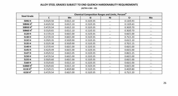
ALLOY STEEL GRADES SUBJECT TO END QUENCH HARDENABILITY REQUIREMENTS (ASTM A 304 – 05)
Steel Grade Chemical Composition Ranges and Limits, PercentA
C Mn Si Ni Cr Mo 5046 H 0.43/0.50 0.65/1.10 0.15/0.35 ... 0.13/0.43 ...
50B46 HC 0.43/0.50 0.65/1.10 0.15/0.35 ... 0.13/0.43 ...
50B50 HC 0.47/0.54 0.65/1.10 0.15/0.35 ... 0.30/0.70 ...
50B60 HC 0.55/0.65 0.65/1.10 0.15/0.35 ... 0.30/0.70 ...
5120 H 0.17/0.23 0.60/1.00 0.15/0.35 ... 0.60/1.00 ...
5130 H 0.27/0.33 0.60/1.00 0.15/0.35 ... 0.75/1.20 ...
5132 H 0.29/0.35 0.50/0.90 0.15/0.35 ... 0.65/1.10 ...
5135 H 0.32/0.38 0.50/0.90 0.15/0.35 ... 0.70/1.15 ...
5140 H 0.37/0.44 0.60/1.00 0.15/0.35 ... 0.60/1.00 ...
5145 H 0.42/0.49 0.60/1.00 0.15/0.35 ... 0.60/1.00 ...
5147 H 0.45/0.52 0.60/1.05 0.15/0.35 ... 0.80/1.25 ...
5150 H 0.47/0.54 0.60/1.00 0.15/0.35 ... 0.60/1.00 ...
5155 H 0.50/0.60 0.60/1.00 0.15/0.35 ... 0.60/1.00 ...
5160 H 0.55/0.65 0.65/1.10 0.15/0.35 ... 0.60/1.00 ...
51B60 HC 0.55/0.65 0.65/1.10 0.15/0.35 ... 0.60/1.00 ...
6118 HD 0.15/0.21 0.40/0.80 0.15/0.35 ... 0.40/0.80 ...
6150 HE 0.47/0.54 0.60/1.00 0.15/0.35 ... 0.75/1.20 ...
27
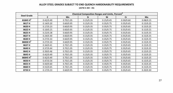
ALLOY STEEL GRADES SUBJECT TO END QUENCH HARDENABILITY REQUIREMENTS (ASTM A 304 – 05)
Steel Grade Chemical Composition Ranges and Limits, PercentA
C Mn Si Ni Cr Mo 81B45 HC
0.42/0.49 0.70/1.05 0.15/0.35 0.15/0.45 0.30/0.60 0.08/0.15
8617 H 0.14/0.20 0.60/0.95 0.15/0.35 0.35/0.75 0.35/0.65 0.15/0.25
8620 H 0.17/0.23 0.60/0.95 0.15/0.35 0.35/0.75 0.35/0.65 0.15/0.25
8622 H 0.19/0.25 0.60/0.95 0.15/0.35 0.35/0.75 0.35/0.65 0.15/0.25
8625 H 0.22/0.28 0.60/0.95 0.15/0.35 0.35/0.75 0.35/0.65 0.15/0.25
8627 H 0.24/0.30 0.60/0.95 0.15/0.35 0.35/0.75 0.35/0.65 0.15/0.25
8630 H 0.27/0.33 0.60/0.95 0.15/0.35 0.35/0.75 0.35/0.65 0.15/0.25
86B30 HC 0.27/0.33 0.60/0.95 0.15/0.35 0.35/0.75 0.35/0.65 0.15/0.25
8637 H 0.34/0.41 0.70/1.05 0.15/0.35 0.35/0.75 0.35/0.65 0.15/0.25
8640 H 0.37/0.44 0.70/1.05 0.15/0.35 0.35/0.75 0.35/0.65 0.15/0.25
8642 H 0.39/0.46 0.70/1.05 0.15/0.35 0.35/0.75 0.35/0.65 0.15/0.25
8645 H 0.42/0.49 0.70/1.05 0.15/0.35 0.35/0.75 0.35/0.65 0.15/0.25
86B45 HC 0.42/0.49 0.70/1.05 0.15/0.35 0.35/0.75 0.35/0.65 0.15/0.25
8650 H 0.47/0.54 0.70/1.05 0.15/0.35 0.35/0.75 0.35/0.65 0.15/0.25
8655 H 0.50/0.60 0.70/1.05 0.15/0.35 0.35/0.75 0.35/0.65 0.15/0.25
8660 H 0.55/0.65 0.70/1.05 0.15/0.35 0.35/0.75 0.35/0.65 0.15/0.25
8720 H 0.17/0.23 0.60/0.95 0.15/0.35 0.35/0.75 0.35/0.65 0.20/0.30
28
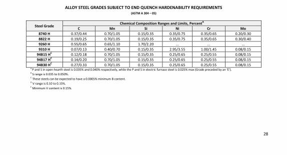
ALLOY STEEL GRADES SUBJECT TO END QUENCH HARDENABILITY REQUIREMENTS (ASTM A 304 – 05)
Steel Grade Chemical Composition Ranges and Limits, PercentA
C Mn Si Ni Cr Mo 8740 H 0.37/0.44 0.70/1.05 0.15/0.35 0.35/0.75 0.35/0.65 0.20/0.30
8822 H 0.19/0.25 0.70/1.05 0.15/0.35 0.35/0.75 0.35/0.65 0.30/0.40
9260 H 0.55/0.65 0.65/1.10 1.70/2.20 ... ... ...
9310 H 0.07/0.13 0.40/0.70 0.15/0.35 2.95/3.55 1.00/1.45 0.08/0.15
94B15 HC 0.12/0.18 0.70/1.05 0.15/0.35 0.25/0.65 0.25/0.55 0.08/0.15
94B17 HC 0.14/0.20 0.70/1.05 0.15/0.35 0.25/0.65 0.25/0.55 0.08/0.15
94B30 HC 0.27/0.33 0.70/1.05 0.15/0.35 0.25/0.65 0.25/0.55 0.08/0.15
A P and S in open-hearth steel is 0.035% and 0.040% respectively, while the P and S in electric furnace steel is 0.025% max (Grade preceded by an ‘E’).
B S range is 0.035 to 0.050%.
C These steels can be expected to have a 0.0005% minimum B content.
D V range is 0.10 to 0.15%.
E Minimum V content is 0.15%.
29
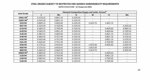
STEEL GRADES SUBJECT TO RESTRICTED END QUENCH HARDENABILITY REQUIREMENTS (ASTM A 914/A 914M – 92; Reapproved 2005)
Steel Grade Chemical Composition Ranges and Limits, PercentA
C Mn Si Ni Cr Mo 15B21 RHB
0.17/0.22 0.80/1.10 0.15/0.35 ... ... ...
15B35 RHB 0.33/0.38 0.80/1.10 0.15/0.35 ... ... ...
3310 RH 0.08/0.13 0.40/0.60 0.15/0.35 3.25/3.75 1.40/1.75 ...
4027 RH 0.25/0.30 0.70/0.90 0.15/0.35 ... ... 0.20/0.30
4118 RH 0.18/0.23 0.70/0.90 0.15/0.35 ... 0.40/0.60 0.08/0.15
4120 RH 0.18/0.23 0.90/1.20 0.15/0.35 ... 0.40/0.60 0.13/0.20
4130 RH 0.28/0.33 0.40/0.60 0.15/0.35 ... 0.80/1.10 0.15/0.25
4140 RH 0.38/0.43 0.75/1.00 0.15/0.35 ... 0.80/1.10 0.15/0.25
4145 RH 0.43/0.48 0.75/1.00 0.15/0.35 ... 0.80/1.10 0.15/0.25
4161 RH 0.56/0.64 0.75/1.00 0.15/0.35 ... 0.70/0.90 0.25/0.35
4320 RH 0.17/0.22 0.45/0.65 0.15/0.35 1.65/2.00 0.40/0.60 0.20/0.30
4620 RH 0.17/0.22 0.45/0.65 0.15/0.35 1.65/2.00 ... 0.20/0.30
4820 RH 0.18/0.23 0.50/0.70 0.15/0.35 3.25/3.75 ... 0.20/0.30
50B40 RHB 0.38/0.43 0.75/1.00 0.15/0.35 ... 0.40/0.60 ...
5130 RH 0.28/0.33 0.70/0.90 0.15/0.35 ... 0.80/1.10 ...
5140 RH 0.38/0.43 0.70/0.90 0.15/0.35 ... 0.70/0.90 ...
5160 RH 0.56/0.64 0.75/1.00 0.15/0.35 ... 0.70/0.90 ...

30
STEEL GRADES SUBJECT TO RESTRICTED END QUENCH HARDENABILITY REQUIREMENTS (ASTM A 914/A 914M – 92; Reapproved 2005)
Steel Grade Chemical Composition Ranges and Limits, PercentA
C Mn Si Ni Cr Mo 8620 RH 0.18/0.23 0.70/0.90 0.15/0.35 0.40/0.70 0.40/0.60 0.15/0.25
8622 RH 0.20/0.25 0.70/0.90 0.15/0.35 0.40/0.70 0.40/0.60 0.15/0.25
8720 RH 0.18/0.23 0.70/0.90 0.15/0.35 0.40/0.70 0.40/0.60 0.20/0.30
8822 RH 0.20/0.25 0.75/1.00 0.15/0.35 0.40/0.70 0.40/0.60 0.30/0.40
9310 RH 0.08/0.13 0.45/0.65 0.15/0.35 3.00/3.50 1.00/1.40 0.08/0.15
A P and S in open-hearth steel is 0.035% and 0.040% max respectively, while P and S in electric furnace steel is 0.025% max.
B These steels can be expected to have 0.0005 to 0.003% B.
31
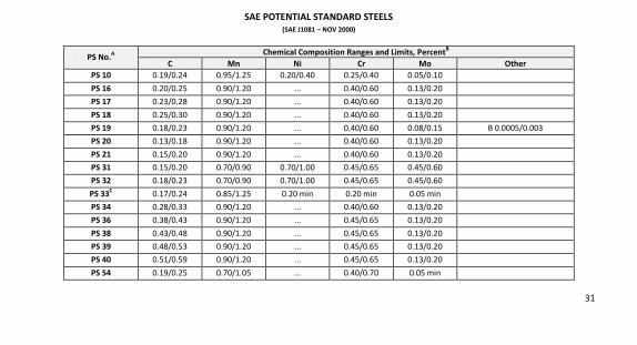
SAE POTENTIAL STANDARD STEELS (SAE J1081 – NOV 2000)
PS No.A Chemical Composition Ranges and Limits, PercentB
C Mn Ni Cr Mo Other PS 10 0.19/0.24 0.95/1.25 0.20/0.40 0.25/0.40 0.05/0.10
PS 16 0.20/0.25 0.90/1.20 ... 0.40/0.60 0.13/0.20
PS 17 0.23/0.28 0.90/1.20 ... 0.40/0.60 0.13/0.20
PS 18 0.25/0.30 0.90/1.20 ... 0.40/0.60 0.13/0.20
PS 19 0.18/0.23 0.90/1.20 ... 0.40/0.60 0.08/0.15 B 0.0005/0.003
PS 20 0.13/0.18 0.90/1.20 ... 0.40/0.60 0.13/0.20
PS 21 0.15/0.20 0.90/1.20 ... 0.40/0.60 0.13/0.20
PS 31 0.15/0.20 0.70/0.90 0.70/1.00 0.45/0.65 0.45/0.60
PS 32 0.18/0.23 0.70/0.90 0.70/1.00 0.45/0.65 0.45/0.60
PS 33C 0.17/0.24 0.85/1.25 0.20 min 0.20 min 0.05 min
PS 34 0.28/0.33 0.90/1.20 ... 0.40/0.60 0.13/0.20
PS 36 0.38/0.43 0.90/1.20 ... 0.45/0.65 0.13/0.20
PS 38 0.43/0.48 0.90/1.20 ... 0.45/0.65 0.13/0.20
PS 39 0.48/0.53 0.90/1.20 ... 0.45/0.65 0.13/0.20
PS 40 0.51/0.59 0.90/1.20 ... 0.45/0.65 0.13/0.20
PS 54 0.19/0.25 0.70/1.05 ... 0.40/0.70 0.05 min
32
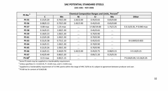
SAE POTENTIAL STANDARD STEELS (SAE J1081 – NOV 2000)
PS No.A Chemical Composition Ranges and Limits, PercentB
C Mn Ni Cr Mo Other PS 55 0.15/0.20 0.70/1.00 1.65/2.00 0.45/0.65 0.65/0.80
PS 56 0.08/0.13 0.70/1.00 1.65/2.00 0.45/0.65 0.65/0.80
PS 57 0.08 max 1.25 max ... 17.00/19.00 1.75/2.25 S 0.15/0.35, P 0.040 max
PS 58 0.16/0.21 1.00/1.30 ... 0.45/0.65 ...
PS 59 0.18/0.23 1.00/1.30 ... 0.70/0.90 ...
PS 61 0.23/0.28 1.00/1.30 ... 0.70/0.90 ...
PS 63 0.31/0.38 0.75/1.10 ... 0.45/0.65 ... B 0.0005/0.003
PS 64 0.16/0.21 1.00/1.30 ... 0.70/0.90 ...
PS 65 0.21/0.26 1.00/1.30 ... 0.70/0.90 ...
PS 66 0.16/0.21 0.40/0.70 1.65/2.00 0.45/0.75 0.08/0.15 V 0.10/0.15
PS 67 0.42/0.49 0.80/1.20 ... 0.85/1.20 0.25/0.35
PS 68D 0.15 max 0.85/1.15 ... ... ... P 0.04/0.09, S 0.26/0.35
A
Some PS steels may be supplied to a hardenability requirement.
B Unless specified, Si = 0.15/0.35, P = 0.025 max, and S = 0.025 max.
C Supplied to a hardenability requirement of 15 HRC points within the range of HRC 23/43 at J4, subject to agreement between producer and user.
D PS 68 has Sn content of 0.04/0.08.
33
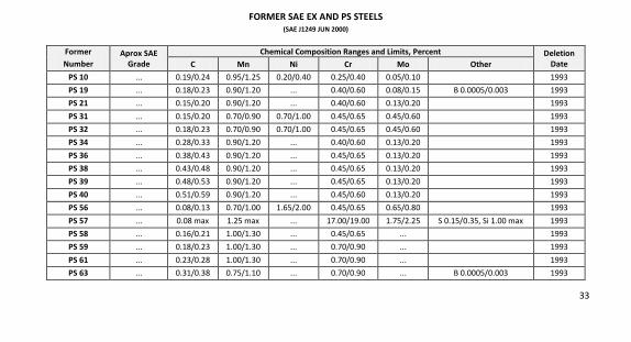
FORMER SAE EX AND PS STEELS (SAE J1249 JUN 2000)
Former Number
Aprox SAE Grade
Chemical Composition Ranges and Limits, Percent Deletion
Date C Mn Ni Cr Mo Other
PS 10 ... 0.19/0.24 0.95/1.25 0.20/0.40 0.25/0.40 0.05/0.10 1993
PS 19 ... 0.18/0.23 0.90/1.20 ... 0.40/0.60 0.08/0.15 B 0.0005/0.003 1993
PS 21 ... 0.15/0.20 0.90/1.20 ... 0.40/0.60 0.13/0.20 1993
PS 31 ... 0.15/0.20 0.70/0.90 0.70/1.00 0.45/0.65 0.45/0.60 1993
PS 32 ... 0.18/0.23 0.70/0.90 0.70/1.00 0.45/0.65 0.45/0.60 1993
PS 34 ... 0.28/0.33 0.90/1.20 ... 0.40/0.60 0.13/0.20 1993
PS 36 ... 0.38/0.43 0.90/1.20 ... 0.45/0.65 0.13/0.20 1993
PS 38 ... 0.43/0.48 0.90/1.20 ... 0.45/0.65 0.13/0.20 1993
PS 39 ... 0.48/0.53 0.90/1.20 ... 0.45/0.65 0.13/0.20 1993
PS 40 ... 0.51/0.59 0.90/1.20 ... 0.45/0.60 0.13/0.20 1993
PS 56 ... 0.08/0.13 0.70/1.00 1.65/2.00 0.45/0.65 0.65/0.80 1993
PS 57 ... 0.08 max 1.25 max ... 17.00/19.00 1.75/2.25 S 0.15/0.35, Si 1.00 max 1993
PS 58 ... 0.16/0.21 1.00/1.30 ... 0.45/0.65 ... 1993
PS 59 ... 0.18/0.23 1.00/1.30 ... 0.70/0.90 ... 1993
PS 61 ... 0.23/0.28 1.00/1.30 ... 0.70/0.90 ... 1993
PS 63 ... 0.31/0.38 0.75/1.10 ... 0.70/0.90 ... B 0.0005/0.003 1993
34
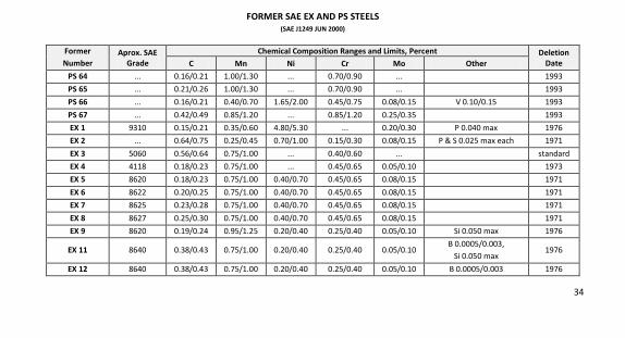
FORMER SAE EX AND PS STEELS (SAE J1249 JUN 2000)
Former Number
Aprox. SAE Grade
Chemical Composition Ranges and Limits, Percent Deletion
Date C Mn Ni Cr Mo Other
PS 64 ... 0.16/0.21 1.00/1.30 ... 0.70/0.90 ... 1993
PS 65 ... 0.21/0.26 1.00/1.30 ... 0.70/0.90 ... 1993
PS 66 ... 0.16/0.21 0.40/0.70 1.65/2.00 0.45/0.75 0.08/0.15 V 0.10/0.15 1993
PS 67 ... 0.42/0.49 0.85/1.20 ... 0.85/1.20 0.25/0.35 1993
EX 1 9310 0.15/0.21 0.35/0.60 4.80/5.30 ... 0.20/0.30 P 0.040 max 1976
EX 2 ... 0.64/0.75 0.25/0.45 0.70/1.00 0.15/0.30 0.08/0.15 P & S 0.025 max each 1971
EX 3 5060 0.56/0.64 0.75/1.00 ... 0.40/0.60 ... standard
EX 4 4118 0.18/0.23 0.75/1.00 ... 0.45/0.65 0.05/0.10 1973
EX 5 8620 0.18/0.23 0.75/1.00 0.40/0.70 0.45/0.65 0.08/0.15 1971
EX 6 8622 0.20/0.25 0.75/1.00 0.40/0.70 0.45/0.65 0.08/0.15 1971
EX 7 8625 0.23/0.28 0.75/1.00 0.40/0.70 0.45/0.65 0.08/0.15 1971
EX 8 8627 0.25/0.30 0.75/1.00 0.40/0.70 0.45/0.65 0.08/0.15 1971
EX 9 8620 0.19/0.24 0.95/1.25 0.20/0.40 0.25/0.40 0.05/0.10 Si 0.050 max 1976
EX 11 8640 0.38/0.43 0.75/1.00 0.20/0.40 0.25/0.40 0.05/0.10 B 0.0005/0.003,
Si 0.050 max 1976
EX 12 8640 0.38/0.43 0.75/1.00 0.20/0.40 0.25/0.40 0.05/0.10 B 0.0005/0.003 1976
35
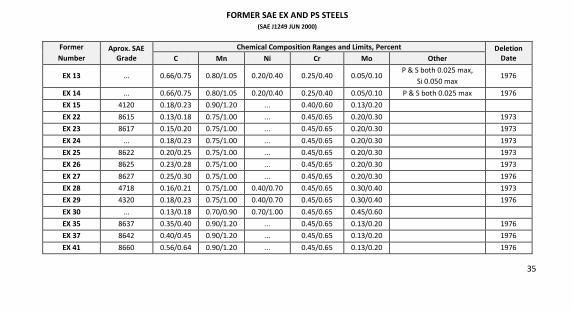
FORMER SAE EX AND PS STEELS (SAE J1249 JUN 2000)
Former Number
Aprox. SAE Grade
Chemical Composition Ranges and Limits, Percent Deletion
Date C Mn Ni Cr Mo Other
EX 13 ... 0.66/0.75 0.80/1.05 0.20/0.40 0.25/0.40 0.05/0.10 P & S both 0.025 max,
Si 0.050 max 1976
EX 14 ... 0.66/0.75 0.80/1.05 0.20/0.40 0.25/0.40 0.05/0.10 P & S both 0.025 max 1976
EX 15 4120 0.18/0.23 0.90/1.20 ... 0.40/0.60 0.13/0.20
EX 22 8615 0.13/0.18 0.75/1.00 ... 0.45/0.65 0.20/0.30 1973
EX 23 8617 0.15/0.20 0.75/1.00 ... 0.45/0.65 0.20/0.30 1973
EX 24 ... 0.18/0.23 0.75/1.00 ... 0.45/0.65 0.20/0.30 1973
EX 25 8622 0.20/0.25 0.75/1.00 ... 0.45/0.65 0.20/0.30 1973
EX 26 8625 0.23/0.28 0.75/1.00 ... 0.45/0.65 0.20/0.30 1973
EX 27 8627 0.25/0.30 0.75/1.00 ... 0.45/0.65 0.20/0.30 1976
EX 28 4718 0.16/0.21 0.75/1.00 0.40/0.70 0.45/0.65 0.30/0.40 1973
EX 29 4320 0.18/0.23 0.75/1.00 0.40/0.70 0.45/0.65 0.30/0.40 1976
EX 30 ... 0.13/0.18 0.70/0.90 0.70/1.00 0.45/0.65 0.45/0.60
EX 35 8637 0.35/0.40 0.90/1.20 ... 0.45/0.65 0.13/0.20 1976
EX 37 8642 0.40/0.45 0.90/1.20 ... 0.45/0.65 0.13/0.20 1976
EX 41 8660 0.56/0.64 0.90/1.20 ... 0.45/0.65 0.13/0.20 1976
36
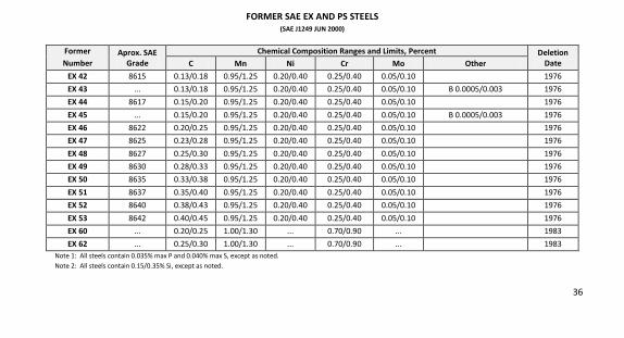
FORMER SAE EX AND PS STEELS (SAE J1249 JUN 2000)
Former Number
Aprox. SAE Grade
Chemical Composition Ranges and Limits, Percent Deletion
Date C Mn Ni Cr Mo Other
EX 42 8615 0.13/0.18 0.95/1.25 0.20/0.40 0.25/0.40 0.05/0.10 1976
EX 43 ... 0.13/0.18 0.95/1.25 0.20/0.40 0.25/0.40 0.05/0.10 B 0.0005/0.003 1976
EX 44 8617 0.15/0.20 0.95/1.25 0.20/0.40 0.25/0.40 0.05/0.10 1976
EX 45 ... 0.15/0.20 0.95/1.25 0.20/0.40 0.25/0.40 0.05/0.10 B 0.0005/0.003 1976
EX 46 8622 0.20/0.25 0.95/1.25 0.20/0.40 0.25/0.40 0.05/0.10 1976
EX 47 8625 0.23/0.28 0.95/1.25 0.20/0.40 0.25/0.40 0.05/0.10 1976
EX 48 8627 0.25/0.30 0.95/1.25 0.20/0.40 0.25/0.40 0.05/0.10 1976
EX 49 8630 0.28/0.33 0.95/1.25 0.20/0.40 0.25/0.40 0.05/0.10 1976
EX 50 8635 0.33/0.38 0.95/1.25 0.20/0.40 0.25/0.40 0.05/0.10 1976
EX 51 8637 0.35/0.40 0.95/1.25 0.20/0.40 0.25/0.40 0.05/0.10 1976
EX 52 8640 0.38/0.43 0.95/1.25 0.20/0.40 0.25/0.40 0.05/0.10 1976
EX 53 8642 0.40/0.45 0.95/1.25 0.20/0.40 0.25/0.40 0.05/0.10 1976
EX 60 ... 0.20/0.25 1.00/1.30 ... 0.70/0.90 ... 1983
EX 62 ... 0.25/0.30 1.00/1.30 ... 0.70/0.90 ... 1983
Note 1: All steels contain 0.035% max P and 0.040% max S, except as noted.
Note 2: All steels contain 0.15/0.35% Si, except as noted.
37
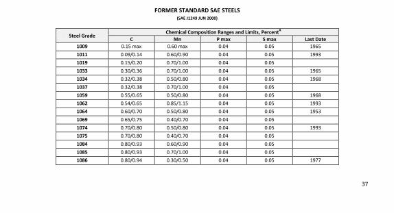
FORMER STANDARD SAE STEELS (SAE J1249 JUN 2000)
Steel Grade Chemical Composition Ranges and Limits, PercentA
C Mn P max S max Last Date 1009 0.15 max 0.60 max 0.04 0.05 1965
1011 0.09/0.14 0.60/0.90 0.04 0.05 1993
1019 0.15/0.20 0.70/1.00 0.04 0.05
1033 0.30/0.36 0.70/1.00 0.04 0.05 1965
1034 0.32/0.38 0.50/0.80 0.04 0.05 1968
1037 0.32/0.38 0.70/1.00 0.04 0.05
1059 0.55/0.65 0.50/0.80 0.04 0.05 1968
1062 0.54/0.65 0.85/1.15 0.04 0.05 1993
1064 0.60/0.70 0.50/0.80 0.04 0.05 1953
1069 0.65/0.75 0.40/0.70 0.04 0.05
1074 0.70/0.80 0.50/0.80 0.04 0.05 1993
1075 0.70/0.80 0.40/0.70 0.04 0.05
1084 0.80/0.93 0.60/0.90 0.04 0.05
1085 0.80/0.93 0.70/1.00 0.04 0.05
1086 0.80/0.94 0.30/0.50 0.04 0.05 1977
38
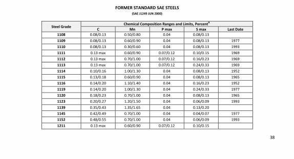
FORMER STANDARD SAE STEELS (SAE J1249 JUN 2000)
Steel Grade Chemical Composition Ranges and Limits, PercentA
C Mn P max S max Last Date 1108 0.08/0.13 0.50/0.80 0.04 0.08/0.13
1109 0.08/0.13 0.60/0.90 0.04 0.08/0.13 1977
1110 0.08/0.13 0.30/0.60 0.04 0.08/0.13 1993
1111 0.13 max 0.60/0.90 0.07/0.12 0.10/0.15 1969
1112 0.13 max 0.70/1.00 0.07/0.12 0.16/0.23 1969
1113 0.13 max 0.70/1.00 0.07/0.12 0.24/0.33 1969
1114 0.10/0.16 1.00/1.30 0.04 0.08/0.13 1952
1115 0.13/0.18 0.60/0.90 0.04 0.08/0.13 1965
1116 0.14/0.20 1.10/1.40 0.04 0.16/0.23 1952
1119 0.14/0.20 1.00/1.30 0.04 0.24/0.33 1977
1120 0.18/0.23 0.70/1.00 0.04 0.08/0.13 1965
1123 0.20/0.27 1.20/1.50 0.04 0.06/0.09 1993
1139 0.35/0.43 1.35/1.65 0.04 0.13/0.20
1145 0.42/0.49 0.70/1.00 0.04 0.04/0.07 1977
1152 0.48/0.55 0.70/1.00 0.04 0.06/0.09 1993
1211 0.13 max 0.60/0.90 0.07/0.12 0.10/0.15

39
FORMER STANDARD SAE STEELS (SAE J1249 JUN 2000)
Steel Grade Chemical Composition Ranges and Limits, PercentA
C Mn P max S max Last Date 1513 0.10/0.16 1.10/1.40 0.04 0.05 1993
1518 0.15/0.21 1.10/1.40 0.04 0.05 1977
1525 0.23/0.29 0.80/1.10 0.04 0.05 1977
1533 0.30/0.37 1.10/1.40 0.04 0.05 1993
1534 0.30/0.37 1.20/1.50 0.04 0.05 1993
1536 0.30/0.37 1.20/1.50 0.04 0.05
1544 0.40/0.47 0.80/1.10 0.04 0.05 1993
1545 0.43/0.50 0.80/1.10 0.04 0.05 1993
1546 0.44/0.52 1.00/1.30 0.04 0.05 1993
1551 0.45/0.56 0.85/1.15 0.04 0.05
1553 0.48/0.55 0.80/1.10 0.04 0.05 1993
1561 0.55/0.65 0.75/1.05 0.04 0.05
1570 0.65/0.75 0.80/1.10 0.04 0.05 1993
1572 0.65/0.76 1.00/1.30 0.04 0.05 1977
1580 0.75/0.88 0.80/1.10 0.04 0.05 1993
1590 0.85/0.98 0.80/1.10 0.04 0.05 1993
40
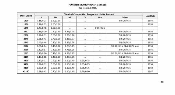
FORMER STANDARD SAE STEELS (SAE J1249 JUN 2000)
Steel Grade Chemical Composition Ranges and Limits, Percent
Last Date C Mn Ni Cr Mo Other
1320 0.18/0.23 1.60/1.90 ... ... ... Si 0.20/0.35 1956
1330 0.28/0.33 1.60/1.90 ... ... ... 1993
1345 0.43/0.48 1.60/1.90 ... ... 0.15/0.25
2317 0.15/0.20 0.40/0.60 3.25/3.75 ... ... Si 0.20/0.35 1956
2330 0.28/0.33 0.60/0.80 3.25/3.76 ... ... Si 0.20/0.35 1953
2340 0.38/0.43 0.70/0.90 3.25/3.77 ... ... Si 0.20/0.35 1953
2345 0.43/0.48 0.70/0.90 3.25/3.78 ... ... Si 0.20/0.35 1952
2512 0.09/0.14 0.45/0.60 4.75/5.25 ... ... Si 0.20/0.35, P&S 0.025 max 1953
2515 0.12/0.17 0.40/0.60 4.75/5.25 ... ... Si 0.20/0.35 1956
2517 0.15/0.20 0.45/0.60 4.75/5.25 ... ... Si 0.20/0.35, P&S 0.025 max 1959
3115 0.13/0.18 0.40/0.60 3.25/3.75 ... ... Si 0.20/0.35 1956
3120 0.17/0.22 0.60/0.80 1.10/1.40 0.55/0.75 ... Si 0.20/0.35 1956
3130 0.28/0.33 0.60/0.80 1.10/1.40 0.55/0.75 ... Si 0.20/0.35 1956
3135 0.33/0.38 0.60/0.80 1.10/1.40 0.55/0.75 ... Si 0.20/0.35 1960
X3140 0.38/0.43 0.70/0.90 1.10/1.40 0.70/0.90 ... Si 0.20/0.35 1947
41
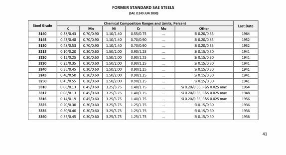
FORMER STANDARD SAE STEELS (SAE J1249 JUN 2000)
Steel Grade Chemical Composition Ranges and Limits, Percent
Last Date C Mn Ni Cr Mo Other
3140 0.38/0.43 0.70/0.90 1.10/1.40 0.55/0.75 ... Si 0.20/0.35 1964
3145 0.43/0.48 0.70/0.90 1.10/1.40 0.70/0.90 ... Si 0.20/0.35 1952
3150 0.48/0.53 0.70/0.90 1.10/1.40 0.70/0.90 ... Si 0.20/0.35 1952
3215 0.10/0.20 0.30/0.60 1.50/2.00 0.90/1.25 ... Si 0.15/0.30 1941
3220 0.15/0.25 0.30/0.60 1.50/2.00 0.90/1.25 ... Si 0.15/0.30 1941
3230 0.25/0.35 0.30/0.60 1.50/2.00 0.90/1.25 ... Si 0.15/0.30 1941
3240 0.35/0.45 0.30/0.60 1.50/2.00 0.90/1.25 ... Si 0.15/0.30 1941
3245 0.40/0.50 0.30/0.60 1.50/2.00 0.90/1.25 ... Si 0.15/0.30 1941
3250 0.45/0.55 0.30/0.60 1.50/2.00 0.90/1.25 ... Si 0.15/0.30 1941
3310 0.08/0.13 0.45/0.60 3.25/3.75 1.40/1.75 ... Si 0.20/0.35, P&S 0.025 max 1964
3312 0.08/0.13 0.45/0.60 3.25/3.75 1.40/1.75 ... Si 0.20/0.35, P&S 0.025 max 1948
3316 0.14/0.19 0.45/0.60 3.25/3.75 1.40/1.75 ... Si 0.20/0.35, P&S 0.025 max 1956
3325 0.20/0.30 0.30/0.60 3.25/3.75 1.25/1.75 ... Si 0.15/0.30 1936
3335 0.30/0.40 0.30/0.60 3.25/3.75 1.25/1.75 ... Si 0.15/0.30 1936
3340 0.35/0.45 0.30/0.60 3.25/3.75 1.25/1.75 ... Si 0.15/0.30 1936
42
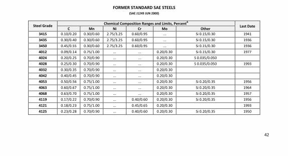
FORMER STANDARD SAE STEELS (SAE J1249 JUN 2000)
Steel Grade Chemical Composition Ranges and Limits, PercentA
Last Date C Mn Ni Cr Mo Other
3415 0.10/0.20 0.30/0.60 2.75/3.25 0.60/0.95 ... Si 0.15/0.30 1941
3435 0.30/0.40 0.30/0.60 2.75/3.25 0.60/0.95 ... Si 0.15/0.30 1936
3450 0.45/0.55 0.30/0.60 2.75/3.25 0.60/0.95 ... Si 0.15/0.30 1936
4012 0.09/0.14 0.75/1.00 ... ... 0.20/0.30 Si 0.15/0.30 1977
4024 0.20/0.25 0.70/0.90 ... ... 0.20/0.30 S 0.035/0.050
4028 0.25/0.30 0.70/0.90 ... ... 0.20/0.30 S 0.035/0.050 1993
4032 0.30/0.35 0.70/0.90 ... ... 0.20/0.30
4042 0.40/0.45 0.70/0.90 ... ... 0.20/0.30
4053 0.50/0.56 0.75/1.00 ... ... 0.20/0.30 Si 0.20/0.35 1956
4063 0.60/0.67 0.75/1.00 ... ... 0.20/0.30 Si 0.20/0.35 1964
4068 0.63/0.70 0.75/1.00 ... ... 0.20/0.30 Si 0.20/0.35 1957
4119 0.17/0.22 0.70/0.90 ... 0.40/0.60 0.20/0.30 Si 0.20/0.35 1956
4121 0.18/0.23 0.75/1.00 ... 0.45/0.65 0.20/0.30 1993
4125 0.23/0.28 0.70/0.90 ... 0.40/0.60 0.20/0.30 Si 0.20/0.35 1950
43
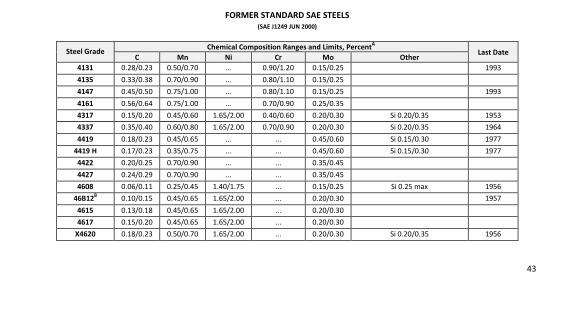
FORMER STANDARD SAE STEELS (SAE J1249 JUN 2000)
Steel Grade Chemical Composition Ranges and Limits, PercentA
Last Date C Mn Ni Cr Mo Other
4131 0.28/0.23 0.50/0.70 ... 0.90/1.20 0.15/0.25 1993
4135 0.33/0.38 0.70/0.90 ... 0.80/1.10 0.15/0.25
4147 0.45/0.50 0.75/1.00 ... 0.80/1.10 0.15/0.25 1993
4161 0.56/0.64 0.75/1.00 ... 0.70/0.90 0.25/0.35
4317 0.15/0.20 0.45/0.60 1.65/2.00 0.40/0.60 0.20/0.30 Si 0.20/0.35 1953
4337 0.35/0.40 0.60/0.80 1.65/2.00 0.70/0.90 0.20/0.30 Si 0.20/0.35 1964
4419 0.18/0.23 0.45/0.65 ... ... 0.45/0.60 Si 0.15/0.30 1977
4419 H 0.17/0.23 0.35/0.75 ... ... 0.45/0.60 Si 0.15/0.30 1977
4422 0.20/0.25 0.70/0.90 ... ... 0.35/0.45
4427 0.24/0.29 0.70/0.90 ... ... 0.35/0.45
4608 0.06/0.11 0.25/0.45 1.40/1.75 ... 0.15/0.25 Si 0.25 max 1956
46B12B 0.10/0.15 0.45/0.65 1.65/2.00 ... 0.20/0.30 1957
4615 0.13/0.18 0.45/0.65 1.65/2.00 ... 0.20/0.30
4617 0.15/0.20 0.45/0.65 1.65/2.00 ... 0.20/0.30
X4620 0.18/0.23 0.50/0.70 1.65/2.00 ... 0.20/0.30 Si 0.20/0.35 1956
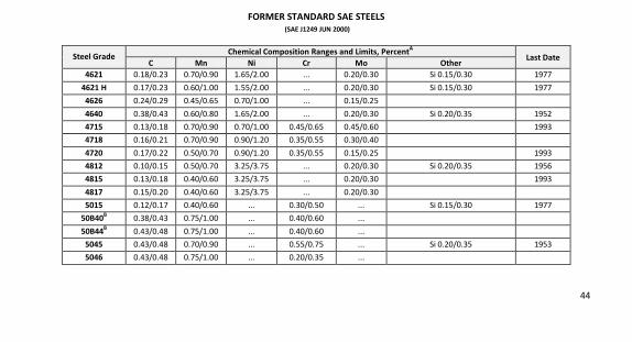
44
FORMER STANDARD SAE STEELS (SAE J1249 JUN 2000)
Steel Grade Chemical Composition Ranges and Limits, PercentA
Last Date C Mn Ni Cr Mo Other
4621 0.18/0.23 0.70/0.90 1.65/2.00 ... 0.20/0.30 Si 0.15/0.30 1977
4621 H 0.17/0.23 0.60/1.00 1.55/2.00 ... 0.20/0.30 Si 0.15/0.30 1977
4626 0.24/0.29 0.45/0.65 0.70/1.00 ... 0.15/0.25
4640 0.38/0.43 0.60/0.80 1.65/2.00 ... 0.20/0.30 Si 0.20/0.35 1952
4715 0.13/0.18 0.70/0.90 0.70/1.00 0.45/0.65 0.45/0.60 1993
4718 0.16/0.21 0.70/0.90 0.90/1.20 0.35/0.55 0.30/0.40
4720 0.17/0.22 0.50/0.70 0.90/1.20 0.35/0.55 0.15/0.25 1993
4812 0.10/0.15 0.50/0.70 3.25/3.75 ... 0.20/0.30 Si 0.20/0.35 1956
4815 0.13/0.18 0.40/0.60 3.25/3.75 ... 0.20/0.30 1993
4817 0.15/0.20 0.40/0.60 3.25/3.75 ... 0.20/0.30
5015 0.12/0.17 0.40/0.60 ... 0.30/0.50 ... Si 0.15/0.30 1977
50B40B 0.38/0.43 0.75/1.00 ... 0.40/0.60 ...
50B44B 0.43/0.48 0.75/1.00 ... 0.40/0.60 ...
5045 0.43/0.48 0.70/0.90 ... 0.55/0.75 ... Si 0.20/0.35 1953
5046 0.43/0.48 0.75/1.00 ... 0.20/0.35 ...
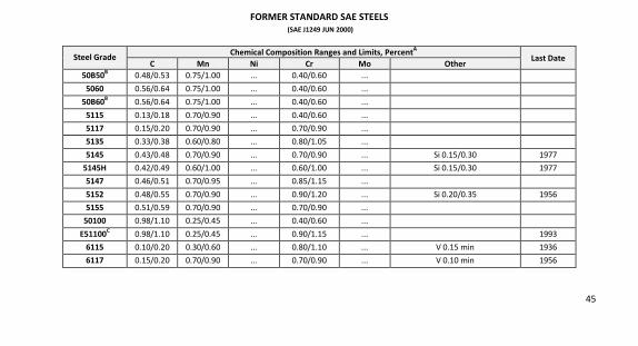
45
FORMER STANDARD SAE STEELS (SAE J1249 JUN 2000)
Steel Grade Chemical Composition Ranges and Limits, PercentA
Last Date C Mn Ni Cr Mo Other
50B50B 0.48/0.53 0.75/1.00 ... 0.40/0.60 ...
5060 0.56/0.64 0.75/1.00 ... 0.40/0.60 ...
50B60B 0.56/0.64 0.75/1.00 ... 0.40/0.60 ...
5115 0.13/0.18 0.70/0.90 ... 0.40/0.60 ...
5117 0.15/0.20 0.70/0.90 ... 0.70/0.90 ...
5135 0.33/0.38 0.60/0.80 ... 0.80/1.05 ...
5145 0.43/0.48 0.70/0.90 ... 0.70/0.90 ... Si 0.15/0.30 1977
5145H 0.42/0.49 0.60/1.00 ... 0.60/1.00 ... Si 0.15/0.30 1977
5147 0.46/0.51 0.70/0.95 ... 0.85/1.15 ...
5152 0.48/0.55 0.70/0.90 ... 0.90/1.20 ... Si 0.20/0.35 1956
5155 0.51/0.59 0.70/0.90 ... 0.70/0.90 ...
50100 0.98/1.10 0.25/0.45 ... 0.40/0.60 ...
E51100C 0.98/1.10 0.25/0.45 ... 0.90/1.15 ... 1993
6115 0.10/0.20 0.30/0.60 ... 0.80/1.10 ... V 0.15 min 1936
6117 0.15/0.20 0.70/0.90 ... 0.70/0.90 ... V 0.10 min 1956
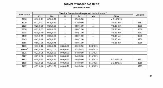
46
FORMER STANDARD SAE STEELS (SAE J1249 JUN 2000)
Steel Grade Chemical Composition Ranges and Limits, PercentA
Last Date C Mn Ni Cr Mo Other
6118 0.16/0.21 0.50/0.70 ... 0.50/0.70 ... V 0.10/0.15
6120 0.17/0.22 0.70/0.90 ... 0.70/0.90 ... V 0.10 min 1961
6125 0.20/0.30 0.60/0.90 ... 0.80/1.10 ... V 0.15 min 1936
6130 0.25/0.35 0.60/0.90 ... 0.80/1.10 ... V 0.15 min 1936
6135 0.30/0.40 0.60/0.90 ... 0.80/1.10 ... V 0.15 min 1941
6140 0.35/0.45 0.60/0.90 ... 0.80/1.10 ... V 0.15 min 1936
6145 0.43/0.48 0.70/0.90 ... 0.80/1.10 ... V 0.15 min 1956
6195 0.90/1.05 0.20/0.45 ... 0.80/1.10 ... V 0.15 min 1936
8115 0.13/0.18 0.70/0.90 0.20/0.40 0.30/0.50 0.08/0.15
81B45B 0.43/0.48 0.75/1.00 0.20/0.40 0.35/0.55 0.08/0.15
8625 0.23/0.28 0.70/0.90 0.40/0.70 0.40/0.60 0.15/0.25
8627 0.25/0.30 0.70/0.90 0.40/0.70 0.40/0.60 0.15/0.25
8632 0.30/0.35 0.70/0.90 0.40/0.70 0.40/0.60 0.15/0.25 Si 0.20/0.35 1951
8635 0.33/0.38 0.75/1.00 0.40/0.70 0.40/0.60 0.15/0.25 Si 0.20/0.35 1956
8637 0.35/0.40 0.75/1.00 0.40/0.70 0.40/0.60 0.15/0.25 1993
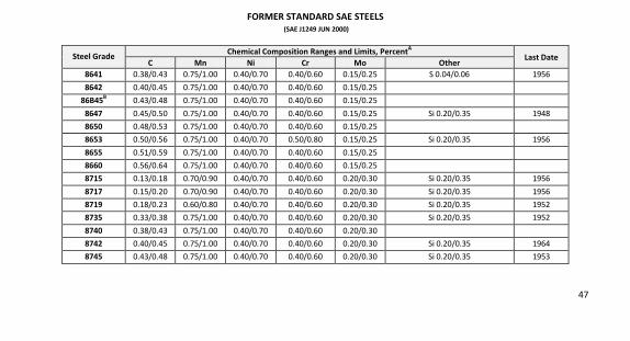
47
FORMER STANDARD SAE STEELS (SAE J1249 JUN 2000)
Steel Grade Chemical Composition Ranges and Limits, PercentA
Last Date C Mn Ni Cr Mo Other
8641 0.38/0.43 0.75/1.00 0.40/0.70 0.40/0.60 0.15/0.25 S 0.04/0.06 1956
8642 0.40/0.45 0.75/1.00 0.40/0.70 0.40/0.60 0.15/0.25
86B45B 0.43/0.48 0.75/1.00 0.40/0.70 0.40/0.60 0.15/0.25
8647 0.45/0.50 0.75/1.00 0.40/0.70 0.40/0.60 0.15/0.25 Si 0.20/0.35 1948
8650 0.48/0.53 0.75/1.00 0.40/0.70 0.40/0.60 0.15/0.25
8653 0.50/0.56 0.75/1.00 0.40/0.70 0.50/0.80 0.15/0.25 Si 0.20/0.35 1956
8655 0.51/0.59 0.75/1.00 0.40/0.70 0.40/0.60 0.15/0.25
8660 0.56/0.64 0.75/1.00 0.40/0.70 0.40/0.60 0.15/0.25
8715 0.13/0.18 0.70/0.90 0.40/0.70 0.40/0.60 0.20/0.30 Si 0.20/0.35 1956
8717 0.15/0.20 0.70/0.90 0.40/0.70 0.40/0.60 0.20/0.30 Si 0.20/0.35 1956
8719 0.18/0.23 0.60/0.80 0.40/0.70 0.40/0.60 0.20/0.30 Si 0.20/0.35 1952
8735 0.33/0.38 0.75/1.00 0.40/0.70 0.40/0.60 0.20/0.30 Si 0.20/0.35 1952
8740 0.38/0.43 0.75/1.00 0.40/0.70 0.40/0.60 0.20/0.30
8742 0.40/0.45 0.75/1.00 0.40/0.70 0.40/0.60 0.20/0.30 Si 0.20/0.35 1964
8745 0.43/0.48 0.75/1.00 0.40/0.70 0.40/0.60 0.20/0.30 Si 0.20/0.35 1953
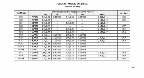
48
FORMER STANDARD SAE STEELS (SAE J1249 JUN 2000)
Steel Grade Chemical Composition Ranges and Limits, PercentA
Last Date C Mn Ni Cr Mo Other
8750 0.48/0.53 0.75/1.00 0.40/0.70 0.40/0.60 0.20/0.30 Si 0.20/0.35 1956
9250 0.45/0.55 0.60/0.90 ... ... ... Si 1.80/2.20 1941
9254 0.51/0.59 0.60/0.80 ... 0.60/0.80 ... Si 1.20/1.60
9255 0.51/0.59 0.70/0.95 ... ... ... Si 1.80/2.20 1977
9261 0.55/0.65 0.75/1.00 ... 0.10/0.25 ... Si 1.80/2.20 1956
9262 0.55/0.65 0.75/1.00 ... 0.25/0.40 ... Si 1.80/2.20 1961
9310 0.08/0.13 0.45/0.65 3.00/3.50 1.00/1.40 0.08/0.15
9315 0.13/0.18 0.45/0.65 3.00/3.50 1.00/1.40 0.08/0.15 Si 0.20/0.35 1959
9317 0.15/0.20 0.45/0.65 3.00/3.50 1.00/1.40 0.08/0.15 Si 0.20/0.35 1959
94B15B 0.13/0.18 0.75/1.00 0.30/0.60 0.30/0.50 0.08/0.15
94B17B 0.15/0.20 0.75/1.00 0.30/0.60 0.30/0.50 0.08/0.15
94B30B 0.28/0.33 0.75/1.00 0.30/0.60 0.30/0.50 0.08/0.15
9437 0.35/0.40 0.90/1.20 0.30/0.60 0.30/0.50 0.08/0.15 Si 0.20/0.35 1950
9440 0.38/0.43 0.90/1.20 0.30/0.60 0.30/0.50 0.08/0.15 Si 0.20/0.35 1950
94B40B 0.38/0.43 0.75/1.00 0.30/0.60 0.30/0.50 0.08/0.15 1964
49
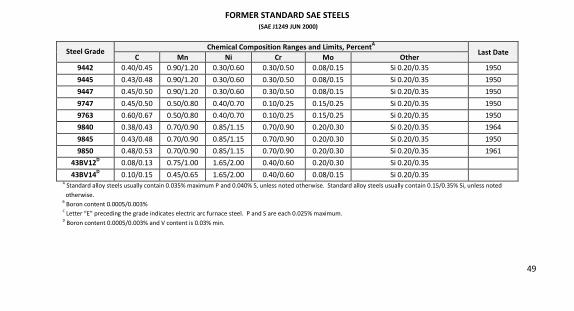
FORMER STANDARD SAE STEELS (SAE J1249 JUN 2000)
Steel Grade Chemical Composition Ranges and Limits, PercentA
Last Date C Mn Ni Cr Mo Other
9442 0.40/0.45 0.90/1.20 0.30/0.60 0.30/0.50 0.08/0.15 Si 0.20/0.35 1950
9445 0.43/0.48 0.90/1.20 0.30/0.60 0.30/0.50 0.08/0.15 Si 0.20/0.35 1950
9447 0.45/0.50 0.90/1.20 0.30/0.60 0.30/0.50 0.08/0.15 Si 0.20/0.35 1950
9747 0.45/0.50 0.50/0.80 0.40/0.70 0.10/0.25 0.15/0.25 Si 0.20/0.35 1950
9763 0.60/0.67 0.50/0.80 0.40/0.70 0.10/0.25 0.15/0.25 Si 0.20/0.35 1950
9840 0.38/0.43 0.70/0.90 0.85/1.15 0.70/0.90 0.20/0.30 Si 0.20/0.35 1964
9845 0.43/0.48 0.70/0.90 0.85/1.15 0.70/0.90 0.20/0.30 Si 0.20/0.35 1950
9850 0.48/0.53 0.70/0.90 0.85/1.15 0.70/0.90 0.20/0.30 Si 0.20/0.35 1961
43BV12D 0.08/0.13 0.75/1.00 1.65/2.00 0.40/0.60 0.20/0.30 Si 0.20/0.35
43BV14D 0.10/0.15 0.45/0.65 1.65/2.00 0.40/0.60 0.08/0.15 Si 0.20/0.35
A Standard alloy steels usually contain 0.035% maximum P and 0.040% S, unless noted otherwise. Standard alloy steels usually contain 0.15/0.35% Si, unless noted
otherwise.
B Boron content 0.0005/0.003%
C Letter “E” preceding the grade indicates electric arc furnace steel. P and S are each 0.025% maximum.
D Boron content 0.0005/0.003% and V content is 0.03% min.
50
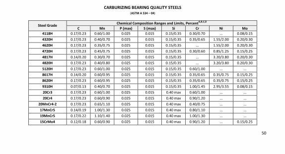
CARBURIZING BEARING QUALITY STEELS (ASTM A 534 – 04)
Steel Grade Chemical Composition Ranges and Limits, PercentA,B,C,D
C Mn P (max) S (max) Si Cr Ni Mo 4118H 0.17/0.23 0.60/1.00 0.025 0.015 0.15/0.35 0.30/0.70 ... 0.08/0.15
4320H 0.17/0.23 0.40/0.70 0.025 0.015 0.15/0.35 0.35/0.65 1.55/2.00 0.20/0.30
4620H 0.17/0.23 0.35/0.75 0.025 0.015 0.15/0.35 ... 1.55/2.00 0.20/0.30
4720H 0.17/0.23 0.45/0.75 0.025 0.015 0.15/0.35 0.30/0.60 0.85/1.25 0.15/0.25
4817H 0.14/0.20 0.30/0.70 0.025 0.015 0.15/0.35 ... 3.20/3.80 0.20/0.30
4820H 0.17/0.23 0.40/0.80 0.025 0.015 0.15/0.35 ... 3.20/3.80 0.20/0.30
5120H 0.17/0.23 0.60/1.00 0.025 0.015 0.15/0.35 0.60/1.00 ... ...
8617H 0.14/0.20 0.60/0.95 0.025 0.015 0.15/0.35 0.35/0.65 0.35/0.75 0.15/0.25
8620H 0.17/0.23 0.60/0.95 0.025 0.015 0.15/0.35 0.35/0.65 0.35/0.75 0.15/0.25
9310H 0.07/0.13 0.40/0.70 0.025 0.015 0.15/0.35 1.00/1.45 2.95/3.55 0.08/0.15
20Cr3 0.17/0.23 0.60/1.00 0.025 0.015 0.40 max 0.60/1.00 ... ...
20Cr4 0.17/0.23 0.60/0.90 0.025 0.015 0.40 max 0.90/1.20 ... ...
20MnCr4-2 0.17/0.23 0.65/1.10 0.025 0.015 0.40 max 0.40/0.75 ... ...
17MnCr5 0.14/0.19 1.00/1.30 0.025 0.015 0.40 max 0.80/1.10 ... ...
19MnCr5 0.17/0.22 1.10/1.40 0.025 0.015 0.40 max 1.00/1.30 ... ...
15CrMo4 0.12/0.18 0.60/0.90 0.025 0.015 0.40 max 0.90/1.20 ... 0.15/0.25
51
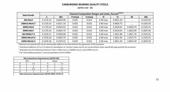
CARBURIZING BEARING QUALITY STEELS (ASTM A 534 – 04)
Steel Grade Chemical Composition Ranges and Limits, PercentA,B,C,D
C Mn P (max) S (max) Si Cr Ni Mo 20CrMo4 0.17/0.23 0.60/0.90 0.025 0.015 0.40 max 0.90/1.20 ... 0.15/0.25
20MnCrMo4-2 0.17/0.23 0.65/1.10 0.025 0.015 0.40 max 0.40/0.75 ... 0.10/0.20
20NiCrMo2 0.17/0.23 0.60/0.95 0.025 0.015 0.40 max 0.35/0.65 0.40/0.70 0.15/0.25
20NiCrMo7 0.17/0.23 0.40/0.70 0.025 0.015 0.40 max 0.35/0.65 1.60/2.00 0.20/0.30
18CrNiMo7-6 0.15/0.21 0.50/0.90 0.025 0.015 0.40 max 1.50/1.80 1.40/1.70 0.25/0.35
18NiCrMo14-6 0.15/0.20 0.40/0.70 0.025 0.015 0.40 max 1.30/1.60 3.25/3.75 0.15/0.25
16NiCrMo16-5 0.14/0.18 0.25/0.55 0.025 0.015 0.40 max 1.00/1.40 3.80/4.30 0.20/0.30 A
Elements not quoted shall not be intentionally added to the steel without the agreement of the purchaser.
B Intentional additions of Ca or Ca alloys for deoxidation or inclusion shape control are not permitted unless specifically approved by the purchaser.
C All grades have the following maximum limits: 0.30% max Cu, 0.0020% max O, and 0.050% max Al.
D For machinability purposes, S may be specified as 0.015-0.030%.
Microcleanliness Requirements (ASTM E45) Thin Heavy
A
2.5 A
1.5
B 2 B 1
C 0.5 C 0.5
D 1 D 1
Macrostructure Requirements (ASTM E381): S2 R2 C2
52
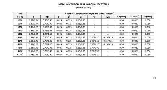
MEDIUM CARBON BEARING QUALITY STEELS (ASTM A 866 – 01)
Steel Grade
Chemical Composition Ranges and Limits, PercentA,B
C Mn PC SC Si Cr Mo Cu (max) O (max)D Al (max)
1030 0.28/0.34 0.60/0.90 0.025 0.025 0.15/0.35 … … 0.30 0.0020 0.050
1040 0.37/0.44 0.60/0.90 0.025 0.025 0.15/0.35 … … 0.30 0.0020 0.050
1050 0.48/0.55 0.60/0.90 0.025 0.025 0.15/0.35 … … 0.30 0.0020 0.050
1541 0.36/0.44 1.35/1.65 0.025 0.025 0.15/0.35 … … 0.30 0.0020 0.050
1552 0.47/0.55 1.20/1.50 0.025 0.025 0.15/0.35 … … 0.30 0.0020 0.050
4130 0.28/0.33 0.40/0.60 0.025 0.025 0.15/0.35 0.80/1.10 0.15/0.25 0.30 0.0020 0.050
4140 0.38/0.43 0.75/1.00 0.025 0.025 0.15/0.35 0.80/1.10 0.15/0.25 0.30 0.0020 0.050
4150 0.48/0.53 0.75/1.00 0.025 0.025 0.15/0.35 0.80/1.10 0.15/0.25 0.30 0.0020 0.050
5140 0.38/0.43 0.70/0.95 0.025 0.025 0.15/0.35 0.70/0.90 … 0.30 0.0020 0.050
5150 0.48/0.53 0.70/0.90 0.025 0.025 0.15/0.35 0.70/0.90 … 0.30 0.0020 0.050
6150E 0.48/0.53 0.70/0.90 0.025 0.025 0.15/0.35 0.80/1.10 … 0.30 0.0020 0.050
53
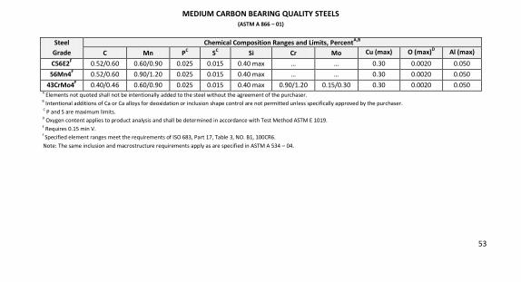
MEDIUM CARBON BEARING QUALITY STEELS (ASTM A 866 – 01)
Steel Grade
Chemical Composition Ranges and Limits, PercentA,B
C Mn PC SC Si Cr Mo Cu (max) O (max)D Al (max)
C56E2F 0.52/0.60 0.60/0.90 0.025 0.015 0.40 max … … 0.30 0.0020 0.050
56Mn4F 0.52/0.60 0.90/1.20 0.025 0.015 0.40 max … … 0.30 0.0020 0.050
43CrMo4F 0.40/0.46 0.60/0.90 0.025 0.015 0.40 max 0.90/1.20 0.15/0.30 0.30 0.0020 0.050
A Elements not quoted shall not be intentionally added to the steel without the agreement of the purchaser.
B Intentional additions of Ca or Ca alloys for deoxidation or inclusion shape control are not permitted unless specifically approved by the purchaser.
C P and S are maximum limits.
D Oxygen content applies to product analysis and shall be determined in accordance with Test Method ASTM E 1019.
E Requires 0.15 min V.
F Specified element ranges meet the requirements of ISO 683, Part 17, Table 3, NO. B1, 100CR6.
Note: The same inclusion and macrostructure requirements apply as are specified in ASTM A 534 – 04.
54
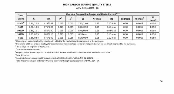
HIGH CARBON BEARING QUALITY STEELS (ASTM A 295/A 295M – 05)
Steel Grade
Chemical Composition Ranges and Limits, PercentA,B,C
C Mn PD SD Cr Ni (max) Mo Cu (max) O (max)E Al (max)F
52100G 0.93/1.05 0.25/0.45 0.025 0.015 1.35/1.60 0.25 0.10 max 0.30 0.0015 0.050
5195 0.90/1.03 0.75/1.00 0.025 0.015 0.70/0.90 0.25 0.10 max 0.30 0.0015 0.050
5090M 0.89/1.01 0.50/0.80 0.025 0.015 0.40/0.60 0.25 0.08/0.15 0.30 0.0015 0.050
1070M 0.65/0.75 0.80/1.10 0.025 0.015 0.20 max 0.25 0.10 max 0.30 0.0015 0.050
5160 0.56/0.64 0.75/1.00 0.025 0.015 0.70/0.90 0.25 0.10 max 0.30 0.0015 0.050 A
Elements not quoted shall not be intentionally added to the steel without the agreement of the purchaser. B
Intentional additions of Ca or Ca alloys for deoxidation or inclusion shape control are not permitted unless specifically approved by the purchaser. C
The Si range for all grades is 0.15/0.35%.
D P and S are maximum limits.
E Oxygen content applies to product analysis and shall be determined in accordance with Test Method ASTM E 1019.
F Total Al content.
G Specified element ranges meet the requirements of ISO 683, Part 17, Table 3, NO. B1, 100CR6.
Note: The same inclusion and macrostructure requirements apply as are specified in ASTM A 534 – 04.
55
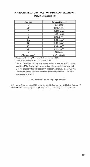
CARBON STEEL FORGINGS FOR PIPING APPLICATIONS (ASTM A 105/A 105M – 09)
Element Composition, % C 0.35 max
Mn 0.60/1.05
P 0.035 max
S 0.040 max
Si 0.10/0.35
Cu 0.40 maxA
Ni 0.40 maxA
Cr 0.30 maxA,B
Mo 0.12 maxA,B
V 0.08 max
C EquivalenceC 0.47 or 0.48
A The sum of C, Ni, Cr, Mo, and V shall not exceed 1.00%.
B The sum of Cr and Mo shall not exceed 0.32%.
C The max C equivalence (Ceq) only applies when specified by the PO. The Ceq
shall be 0.47 for forgings with a max section thickness of 2 in. or less, and
0.48 for forgings with a max section thickness greater than 2 in. A lower max
Ceq may be agreed upon between the supplier and purchaser. The Ceq is
determined as follows:
CE = C + Mn/6 + (Cr + Mo + V)/5 + (Ni + Cu)/15
Note: For each reduction of 0.01% below the specified carbon max (0.35%), an increase of 0.06% Mn above the specified max (1.05%) will be permitted up to a max of 1.35%.
56
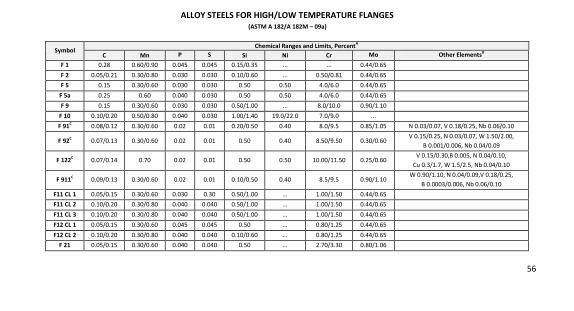
ALLOY STEELS FOR HIGH/LOW TEMPERATURE FLANGES (ASTM A 182/A 182M – 09a)
Symbol Chemical Ranges and Limits, PercentA
C Mn P S Si Ni Cr Mo Other ElementsB
F 1 0.28 0.60/0.90 0.045 0.045 0.15/0.35 ... ... 0.44/0.65
F 2 0.05/0.21 0.30/0.80 0.030 0.030 0.10/0.60 ... 0.50/0.81 0.44/0.65
F 5 0.15 0.30/0.60 0.030 0.030 0.50 0.50 4.0/6.0 0.44/0.65
F 5a 0.25 0.60 0.040 0.030 0.50 0.50 4.0/6.0 0.44/0.65
F 9 0.15 0.30/0.60 0.030 0.030 0.50/1.00 ... 8.0/10.0 0.90/1.10
F 10 0.10/0.20 0.50/0.80 0.040 0.030 1.00/1.40 19.0/22.0 7.0/9.0 ...
F 91C 0.08/0.12 0.30/0.60 0.02 0.01 0.20/0.50 0.40 8.0/9.5 0.85/1.05 N 0.03/0.07, V 0.18/0.25, Nb 0.06/0.10
F 92C 0.07/0.13 0.30/0.60 0.02 0.01 0.50 0.40 8.50/9.50 0.30/0.60
V 0.15/0.25, N 0.03/0.07, W 1.50/2.00,
B 0.001/0.006, Nb 0.04/0.09
F 122C 0.07/0.14 0.70 0.02 0.01 0.50 0.50 10.00/11.50 0.25/0.60
V 0.15/0.30,B 0.005, N 0.04/0.10,
Cu 0.3/1.7, W 1.5/2.5, Nb 0.04/0.10
F 911C 0.09/0.13 0.30/0.60 0.02 0.01 0.10/0.50 0.40 8.5/9.5 0.90/1.10
W 0.90/1.10, N 0.04/0.09,V 0.18/0.25,
B 0.0003/0.006, Nb 0.06/0.10
F11 CL 1 0.05/0.15 0.30/0.60 0.030 0.30 0.50/1.00 … 1.00/1.50 0.44/0.65
F11 CL 2 0.10/0.20 0.30/0.80 0.040 0.040 0.50/1.00 … 1.00/1.50 0.44/0.65
F11 CL 3 0.10/0.20 0.30/0.80 0.040 0.040 0.50/1.00 … 1.00/1.50 0.44/0.65
F12 CL 1 0.05/0.15 0.30/0.60 0.045 0.045 0.50 … 0.80/1.25 0.44/0.65
F12 CL 2 0.10/0.20 0.30/0.80 0.040 0.040 0.10/0.60 … 0.80/1.25 0.44/0.65
F 21 0.05/0.15 0.30/0.60 0.040 0.040 0.50 … 2.70/3.30 0.80/1.06
57
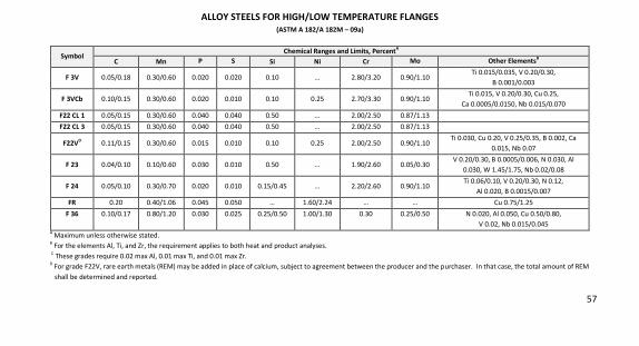
ALLOY STEELS FOR HIGH/LOW TEMPERATURE FLANGES (ASTM A 182/A 182M – 09a)
Symbol Chemical Ranges and Limits, PercentA
C Mn P S Si Ni Cr Mo Other ElementsB
F 3V 0.05/0.18 0.30/0.60 0.020 0.020 0.10 … 2.80/3.20 0.90/1.10 Ti 0.015/0.035, V 0.20/0.30,
B 0.001/0.003
F 3VCb 0.10/0.15 0.30/0.60 0.020 0.010 0.10 0.25 2.70/3.30 0.90/1.10 Ti 0.015, V 0.20/0.30, Cu 0.25,
Ca 0.0005/0.0150, Nb 0.015/0.070
F22 CL 1 0.05/0.15 0.30/0.60 0.040 0.040 0.50 … 2.00/2.50 0.87/1.13
F22 CL 3 0.05/0.15 0.30/0.60 0.040 0.040 0.50 … 2.00/2.50 0.87/1.13
F22VD 0.11/0.15 0.30/0.60 0.015 0.010 0.10 0.25 2.00/2.50 0.90/1.10 Ti 0.030, Cu 0.20, V 0.25/0.35, B 0.002, Ca
0.015, Nb 0.07
F 23 0.04/0.10 0.10/0.60 0.030 0.010 0.50 … 1.90/2.60 0.05/0.30 V 0.20/0.30, B 0.0005/0.006, N 0.030, Al
0.030, W 1.45/1.75, Nb 0.02/0.08
F 24 0.05/0.10 0.30/0.70 0.020 0.010 0.15/0.45 … 2.20/2.60 0.90/1.10 Ti 0.06/0.10, V 0.20/0.30, N 0.12,
Al 0.020, B 0.0015/0.007
FR 0.20 0.40/1.06 0.045 0.050 … 1.60/2.24 … … Cu 0.75/1.25
F 36 0.10/0.17 0.80/1.20 0.030 0.025 0.25/0.50 1.00/1.30 0.30 0.25/0.50 N 0.020, Al 0.050, Cu 0.50/0.80,
V 0.02, Nb 0.015/0.045 A
Maximum unless otherwise stated. B
For the elements Al, Ti, and Zr, the requirement applies to both heat and product analyses.
C These grades require 0.02 max Al, 0.01 max Ti, and 0.01 max Zr.
D For grade F22V, rare earth metals (REM) may be added in place of calcium, subject to agreement between the producer and the purchaser. In that case, the total amount of REM
shall be determined and reported.
58
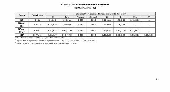
ALLOY STEEL FOR BOLTING APPLICATIONS
(ASTM A193/A193M – 09)
Grade Description Chemical Composition Ranges and Limits, PercentA
C Mn P (max) S (max) Si Cr Mo V B5 5% Cr 0.10 min 1.00 max 0.040 0.030 1.00 max 4.00/6.00 0.40/0.65 …
B6 and B6X
12% Cr 0.08/0.15 1.00 max 0.040 0.030 1.00 max 11.5/13.5 … …
B7 and B7MB Cr-Mo 0.37/0.49 0.65/1.10 0.035 0.040 0.15/0.35 0.75/1.20 0.15/0.25 …
B16C Cr-Mo-V 0.36/0.47 0.45/0.70 0.035 0.040 0.15/0.35 0.80/1.15 0.50/0.65 0.25/0.35
A The intentional addition of Bi, Se, Te, and Pb is not permitted.
B Typical steel compositions used for this grade include 4140, 4142, 4145, 4140H, 4142H, and 4145H.
C Grade B16 has a requirement of 0.015 max Al, total of soluble and insoluble.
59
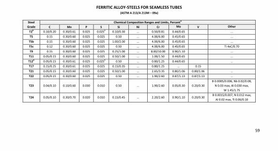
FERRITIC ALLOY-STEELS FOR SEAMLESS TUBES (ASTM A 213/A 213M – 09a)
Steel Grade
Chemical Composition Ranges and Limits, PercentA
C Mn P S Si Ni Cr Mo V Other
T2B 0.10/0.20 0.30/0.61 0.025 0.025B
0.10/0.30 ... 0.50/0.81 0.44/0.65 ...
T5 0.15 0.30/0.60 0.025 0.025 0.50 ... 4.00/6.00 0.45/0.65 ...
T5b 0.15 0.30/0.60 0.025 0.025 1.00/2.00 ... 4.00/6.00 0.45/0.65 ...
T5c 0.12 0.30/0.60 0.025 0.025 0.50 ... 4.00/6.00 0.45/0.65 Ti 4xC/0.70
T9 0.15 0.30/0.60 0.025 0.025 0.25/1.00 ... 8.00/10.00 0.90/1.10 ...
T11 0.05/0.15 0.30/0.60 0.025 0.025 0.50/1.00 ... 1.00/1.50 0.44/0.65 ...
T12B 0.05/0.15 0.30/0.61 0.025 0.025
B 0.50 … 0.80/1.25 0.44/0.65 …
T17 0.15/0.25 0.30/0.61 0.025 0.025 0.15/0.35 … 0.80/1.25 … 0.15
T21 0.05/0.15 0.30/0.60 0.025 0.025 0.50/1.00 … 2.65/3.35 0.80/1.06 0.80/1.06 …
T22 0.05/0.15 0.30/0.60 0.025 0.025 0.50 … 1.90/2.60 0.87/1.13 0.87/1.13 …
T23 0.04/0.10 0.10/0.60 0.030 0.010 0.50 … 1.90/2.60 0.05/0.30 0.20/0.30
B 0.0005/0.006, Nb 0.02/0.08,
N 0.03 max, Al 0.030 max,
W 1.45/1.75
T24 0.05/0.10 0.30/0.70 0.020 0.010 0.15/0.45 … 2.20/2.60 0.90/1.10 0.20/0.30 B 0.0015/0.007, N 0.012 max,
Al 0.02 max, Ti 0.06/0.10
60
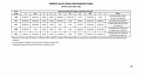
FERRITIC ALLOY-STEELS FOR SEAMLESS TUBES (ASTM A 213/A 213M – 09a)
Steel Grade
Chemical Composition Ranges and Limits, PercentA C Mn P S Si Ni Cr Mo V Other
T36 0.10/0.17 0.80/1.20 0.030 0.025 0.25/0.50 1.00/1.30 0.30 0.25/0.50 0.02 Nb 0.015/0.045, N 0.02,
Al 0.05, Cu 0.50/0.80
T91C 0.07/0.14 0.30/0.60 0.020 0.010 0.20/0.50 0.40 8.0/9.5 0.85/1.05 0.18/0.25 Nb 0.06/0.10, N 0.03/0.07
T92C 0.07/0.13 0.30/0.60 0.020 0.010 0.50 0.40 8.5/9.5 0.30/0.60 0.15/0.25
B 0.001/0.006, Nb 0.04/0.09,
W 1.50/2.00
T122C 0.07/0.14 0.70 0.020 0.010 0.50 0.50 10.0/11.5 0.25/0.60 0.15/0.30
B 0.0005/0.005, N 0.04/0.10,
W 1.50/2.50, Cu 0.30/1.70
T911C 0.09/0.13 0.30/0.60 0.020 0.010 0.10/0.50 0.40 8.5/9.5 0.90/1.10 0.18/0.25
B 0.0003/0.006, Nb 0.06/0.10,
N 0.04/0.09, W 0.90/1.10 A
Maximum, unless range or minimum is indicated. Where ellipses (…) appear in this table, there is no requirement, and analysis for the element need not be determined or
reported. B
It is permissible to ordered T2 and T12 with a S content of 0.045 max. C
These grades require 0.02 max Al, 0.01 max Ti, and 0.01 max Zr.
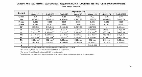
61
CARBON AND LOW-ALLOY STEEL FORGINGS, REQUIRING NOTCH TOUGHNESS TESTING FOR PIPING COMPONENTS (ASTM A 350/A 350M – 07)
Element Composition, wt%
Grade LF1 Grade LF2 Grade LF3 Grade LF5 Grade LF6 Grade LF9 Grade LF787 C, max 0.30 0.30 0.20 0.30 0.22 0.20 0.07
Mn 0.60/1.35 0.60/1.35 0.90 max 0.60/1.35 1.15/1.50 0.40/1.06 0.40/0.70
P, max 0.035 0.035 0.035 0.035 0.025 0.035 0.025
S, max 0.040 0.040 0.040 0.040 0.025 0.040 0.025
SiA 0.15/0.30 0.15/0.30 0.20/0.35 0.20/0.35 0.15/0.30 … 0.40 max
Ni 0.40 maxB 0.40 max
B 3.3/3.7 1.0/2.0 0.40 max
B 1.60/2.24 0.70/1.00
Cr 0.30 maxB,C
0.30 maxB,C
0.30 maxC 0.30 max
C 0.30 max
B,C 0.30 max
C 0.60/0.90
Mo 0.12 maxB,C
0.12 maxB,C
0.12 maxC 0.12 max
C 0.12 max
B,C 0.12 max
C 0.15/0.25
Cu 0.40 maxB 0.40 max
B 0.40 max
C 0.40 max
C 0.40 max
B 0.75/1.25 1.00/1.30
Nb 0.02 maxD
0.02 maxD
0.02 max 0.02 max 0.02 max 0.02 max 0.02 min
V 0.08 max 0.08 max 0.03 max 0.03 max 0.04/0.11 0.03 max 0.03 max
N … … … … 0.01/0.030 … … A
When vacuum carbon-deoxidation is required, the Si content shall be 0.12% max. B
The sum of Cu, Ni, Cr, Mo, and V shall not exceed 1.00% on heat analysis. C
The sum of Cr and Mo shall not exceed 0.32% on heat analysis. D
By agreement, the limit for Nb may be increased up to 0.05% on heat analysis and 0.08% on product analysis.
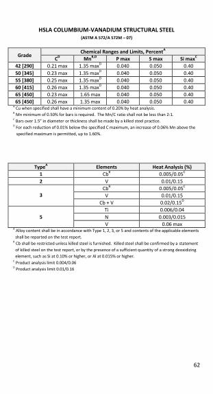
62
HSLA COLUMBIUM-VANADIUM STRUCTURAL STEEL (ASTM A 572/A 572M – 07)
Grade Chemical Ranges and Limits, PercentA
CD MnB,D P max S max Si maxC 42 [290] 0.21 max 1.35 max
D 0.040 0.050 0.40
50 [345] 0.23 max 1.35 maxD 0.040 0.050 0.40
55 [380] 0.25 max 1.35 maxD 0.040 0.050 0.40
60 [415] 0.26 max 1.35 maxD 0.040 0.050 0.40
65 [450] 0.23 max 1.65 max 0.040 0.050 0.40
65 [450] 0.26 max 1.35 max 0.040 0.050 0.40 A Cu when specified shall have a minimum content of 0.20% by heat analysis.
B Mn minimum of 0.50% for bars is required. The Mn/C ratio shall not be less than 2:1.
C Bars over 1.5” in diameter or thickness shall be made by a killed steel practice.
D For each reduction of 0.01% below the specified C maximum, an increase of 0.06% Mn above the
specified maximum is permitted, up to 1.60%.
TypeA Elements Heat Analysis (%) 1 Cb
B 0.005/0.05
C
2 V 0.01/0.15
3
CbB
0.005/0.05C
V 0.01/0.15
Cb + V 0.02/0.15D
5 Ti 0.006/0.04
N 0.003/0.015
V 0.06 max A Alloy content shall be in accordance with Type 1, 2, 3, or 5 and contents of the applicable elements
shall be reported on the test report. B Cb shall be restricted unless killed steel is furnished. Killed steel shall be confirmed by a statement
of killed steel on the test report, or by the presence of a sufficient quantity of a strong deoxidizing
element, such as Si at 0.10% or higher, or Al at 0.015% or higher. C Product analysis limit 0.004/0.06
D Product analysis limit 0.01/0.16
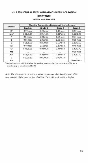
63
HSLA STRUCTURAL STEEL WITH ATMOSPHERIC CORROSION RESISTANCE
(ASTM A 588/A 588M – 05)
Element Chemical Composition Ranges and Limits, Percent
Grade A Grade B Grade C Grade K CA
0.19 max 0.20 max 0.15 max 0.17 max
MnA 0.80/1.25 0.75/1.35 0.80/1.35 0.50/1.20
P 0.04 max 0.04 max 0.04 max 0.04 max
S 0.05 max 0.05 max 0.05 max 0.05 max
Si 0.30/0.65 0.15/0.50 0.15/0.40 0.25/0.50
Ni 0.40 max 0.50 max 0.25/0.50 0.40 max
Cr 0.40/0.65 0.40/0.70 0.30/0.50 0.40/0.70
Mo ... ... ... 0.10 max
Cu 0.25/0.40 0.20/0.40 0.20/0.50 0.30/0.50
V 0.02/0.10 0.01/0.10 0.01/0.10 ...
Cb ... ... ... 0.005/0.05 A For each reduction of 0.01% below the specified maximum for C, an increase of 0.06% Mn is
permitted, up to a maximum of 1.50%.
Note: The atmospheric corrosion resistance index, calculated on the basis of the heat analysis of the steel, as described in ASTM G101, shall be 6.0 or higher.
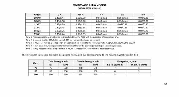
64
MICROALLOY STEEL GRADES (ASTM A 920/A 920M – 07)
Grade C % Mn % P % S % V % 10V40 0.37/0.44 0.60/0.90 0.040 max 0.050 max 0.02/0.20
10V45 0.43/0.50 0.60/0.90 0.040 max 0.050 max 0.02/0.20
11V37 0.32/0.39 1.35/1.65 0.040 max 0.08/0.13 0.02/0.20
11V41 0.37/0.45 1.35/1.65 0.040 max 0.08/0.13 0.02/0.20
15V24 0.19/0.25 1.35/1.65 0.040 max 0.050 max 0.02/0.20
15V41 0.36/0.44 1.35/1.65 0.040 max 0.050 max 0.02/0.20 Note 1: These compositions are identical to those listed In ASTM A576 with the exception of the addition of V.
Note 2: Si content shall be 0.15/0.35% (up to 0.80% may be furnished upon agreement).
Note 3: V, Nb, or Mo may be specified singly or in combination, subject to the following limits: V .02/.20, Nb .005/.07, Mo .01/.30.
Note 4: Ti may be added when specified for refinement of the ferritic-pearlitic (or bainitic) or austenitic grain size.
Note 5: N may be specified as a supplement to V, Nb, or Ti. If specified, N content shall not exceed 0.03%.
Three strength classes are available, designated 75, 80, and 100 corresponding to the minimum yield strength (ksi).
Class Yield Strength, min Tensile Strength, min Elongation, %, min ksi MPa ksi MPa in 8 in. (200mm) in 2 in. (50mm)
75 75 520 100 690 7 10
80 80 550 100 690 6 9
100 100 690 115 790 5 7
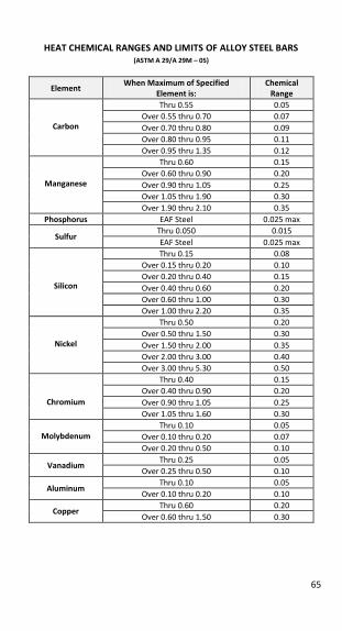
65
HEAT CHEMICAL RANGES AND LIMITS OF ALLOY STEEL BARS (ASTM A 29/A 29M – 05)
Element When Maximum of Specified
Element is: Chemical
Range
Carbon
Thru 0.55 0.05
Over 0.55 thru 0.70 0.07
Over 0.70 thru 0.80 0.09
Over 0.80 thru 0.95 0.11
Over 0.95 thru 1.35 0.12
Manganese
Thru 0.60 0.15
Over 0.60 thru 0.90 0.20
Over 0.90 thru 1.05 0.25
Over 1.05 thru 1.90 0.30
Over 1.90 thru 2.10 0.35
Phosphorus EAF Steel 0.025 max
Sulfur Thru 0.050 0.015
EAF Steel 0.025 max
Silicon
Thru 0.15 0.08
Over 0.15 thru 0.20 0.10
Over 0.20 thru 0.40 0.15
Over 0.40 thru 0.60 0.20
Over 0.60 thru 1.00 0.30
Over 1.00 thru 2.20 0.35
Nickel
Thru 0.50 0.20
Over 0.50 thru 1.50 0.30
Over 1.50 thru 2.00 0.35
Over 2.00 thru 3.00 0.40
Over 3.00 thru 5.30 0.50
Chromium
Thru 0.40 0.15
Over 0.40 thru 0.90 0.20
Over 0.90 thru 1.05 0.25
Over 1.05 thru 1.60 0.30
Molybdenum
Thru 0.10 0.05
Over 0.10 thru 0.20 0.07
Over 0.20 thru 0.50 0.10
Vanadium Thru 0.25 0.05
Over 0.25 thru 0.50 0.10
Aluminum Thru 0.10 0.05
Over 0.10 thru 0.20 0.10
Copper Thru 0.60 0.20
Over 0.60 thru 1.50 0.30
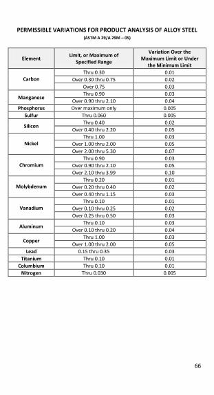
66
PERMISSIBLE VARIATIONS FOR PRODUCT ANALYSIS OF ALLOY STEEL (ASTM A 29/A 29M – 05)
Element
Limit, or Maximum of Specified Range
Variation Over the Maximum Limit or Under
the Minimum Limit
Carbon Thru 0.30 0.01
Over 0.30 thru 0.75 0.02
Over 0.75 0.03
Manganese Thru 0.90 0.03
Over 0.90 thru 2.10 0.04
Phosphorus Over maximum only 0.005
Sulfur Thru 0.060 0.005
Silicon Thru 0.40 0.02
Over 0.40 thru 2.20 0.05
Nickel
Thru 1.00 0.03
Over 1.00 thru 2.00 0.05
Over 2.00 thru 5.30 0.07
Chromium
Thru 0.90 0.03
Over 0.90 thru 2.10 0.05
Over 2.10 thru 3.99 0.10
Molybdenum
Thru 0.20 0.01
Over 0.20 thru 0.40 0.02
Over 0.40 thru 1.15 0.03
Vanadium
Thru 0.10 0.01
Over 0.10 thru 0.25 0.02
Over 0.25 thru 0.50 0.03
Aluminum Thru 0.10 0.03
Over 0.10 thru 0.20 0.04
Copper Thru 1.00 0.03
Over 1.00 thru 2.00 0.05
Lead 0.15 thru 0.35 0.03
Titanium Thru 0.10 0.01
Columbium Thru 0.10 0.01
Nitrogen Thru 0.030 0.005
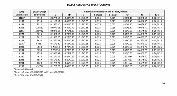
67
SELECT AEROSPACE SPECIFICATIONS
AMS Designation
SAE or Other Equivalent
Chemical Composition and Ranges, Percent C Mn Si P (max) S (max) Cr Ni Mo
6260A 9310 0.07/0.13 0.40/0.70 0.15/0.35 0.025 0.025 1.00/1.40 3.00/3.50 0.08/0.15
6263 9315 0.11/0.17 0.40/0.70 0.15/0.35 0.025 0.025 1.00/1.40 3.00/3.50 0.08/0.15
6264 9317 0.14/0.20 0.40/0.70 0.15/0.35 0.025 0.025 1.00/1.40 3.00/3.50 0.08/0.15
6265 CV9310 0.07/0.13 0.40/0.70 0.15/0.35 0.015 0.015 1.00/1.40 3.00/3.50 0.08/0.15
6266B 43BV12 0.08/0.13 0.75/1.00 0.20/0.40 0.025 0.025 0.40/0.60 1.65/2.00 0.20/0.30
6270 8615 0.13/0.18 0.70/0.90 0.15/0.35 0.025 0.025 0.40/0.60 0.40/0.70 0.15/0.25
6272 8617 0.15/0.20 0.70/0.90 0.15/0.35 0.025 0.025 0.40/0.60 0.40/0.70 0.15/0.25
6274 8620 0.17/0.23 0.60/0.95 0.15/0.35 0.025 0.025 0.35/0.65 0.35/0.75 0.15/0.25
6275C 94B17 0.15/0.20 0.60/0.95 0.15/0.35 0.025 0.025 0.30/0.50 0.30/0.60 0.08/0.15
6280 8630 0.28/033 0.70/0.90 0.15/0.25 0.025 0.025 0.40/0.60 0.40/0.70 0.15/0.25
6281 8630 0.28/033 0.70/0.90 0.15/0.25 0.025 0.025 0.40/0.60 0.40/0.70 0.15/0.25
6282 8735 0.33/0.38 0.75/1.00 0.15/0.35 0.025 0.025 0.40/0.60 0.40/0.70 0.20/0.30
6290 4615 0.11/0.17 0.45/0.65 0.15/0.35 0.025 0.025 0.20 max 1.65/2.00 0.20/0.30
6292 4617 0.15/0.20 0.45/0.65 0.15/0.35 0.025 0.025 0.20 max 1.65/2.00 0.20/0.30
6294 4620 0.17/0.22 0.45/0.65 0.15/0.35 0.025 0.025 0.20 max 1.65/2.00 0.20/0.30
6299 4320H 0.17/0.23 0.40/0.70 0.15/0.35 0.025 0.025 0.35/0.65 1.55/2.00 0.20/0.30
A Requires 0.001 max B
B Requires B range of 0.0005/0.005 and V range of 0.03/0.08
C Requires B range of 0.0005/0.005
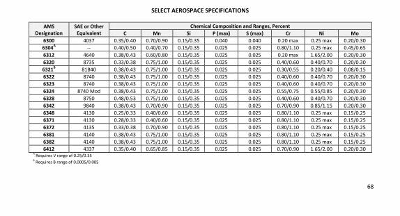
68
SELECT AEROSPACE SPECIFICATIONS
AMS Designation
SAE or Other Equivalent
Chemical Composition and Ranges, Percent C Mn Si P (max) S (max) Cr Ni Mo
6300 4037 0.35/0.40 0.70/0.90 0.15/0.35 0.040 0.040 0.20 max 0.25 max 0.20/0.30
6304A -- 0.40/0.50 0.40/0.70 0.15/0.35 0.025 0.025 0.80/1.10 0.25 max 0.45/0.65
6312 4640 0.38/0.43 0.60/0.80 0.15/0.35 0.025 0.025 0.20 max 1.65/2.00 0.20/0.30
6320 8735 0.33/0.38 0.75/1.00 0.15/0.35 0.025 0.025 0.40/0.60 0.40/0.70 0.20/0.30
6321B 81B40 0.38/0.43 0.75/1.00 0.15/0.35 0.025 0.025 0.30/0.55 0.20/0.40 0.08/0.15
6322 8740 0.38/0.43 0.75/1.00 0.15/0.35 0.025 0.025 0.40/0.60 0.40/0.70 0.20/0.30
6323 8740 0.38/0.43 0.75/1.00 0.15/0.35 0.025 0.025 0.40/0.60 0.40/0.70 0.20/0.30
6324 8740 Mod 0.38/0.43 0.75/1.00 0.15/0.35 0.025 0.025 0.55/0.75 0.55/0.85 0.20/0.30
6328 8750 0.48/0.53 0.75/1.00 0.15/0.35 0.025 0.025 0.40/0.60 0.40/0.70 0.20/0.30
6342 9840 0.38/0.43 0.70/0.90 0.15/0.35 0.025 0.025 0.70/0.90 0.85/1.15 0.20/0.30
6348 4130 0.25/0.33 0.40/0.60 0.15/0.35 0.025 0.025 0.80/1.10 0.25 max 0.15/0.25
6371 4130 0.28/0.33 0.40/0.60 0.15/0.35 0.025 0.025 0.80/1.10 0.25 max 0.15/0.25
6372 4135 0.33/0.38 0.70/0.90 0.15/0.35 0.025 0.025 0.80/1.10 0.25 max 0.15/0.25
6381 4140 0.38/0.43 0.75/1.00 0.15/0.35 0.025 0.025 0.80/1.10 0.25 max 0.15/0.25
6382 4140 0.38/0.43 0.75/1.00 0.15/0.35 0.025 0.025 0.80/1.10 0.25 max 0.15/0.25
6412 4337 0.35/0.40 0.65/0.85 0.15/0.35 0.025 0.025 0.70/0.90 1.65/2.00 0.20/0.30
A Requires V range of 0.25/0.35
B Requires B range of 0.0005/0.005
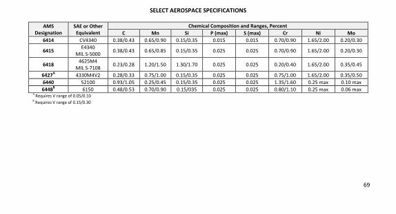
69
SELECT AEROSPACE SPECIFICATIONS
AMS Designation
SAE or Other Equivalent
Chemical Composition and Ranges, Percent C Mn Si P (max) S (max) Cr Ni Mo
6414 CV4340 0.38/0.43 0.65/0.90 0.15/0.35 0.015 0.015 0.70/0.90 1.65/2.00 0.20/0.30
6415 E4340
MIL S-5000 0.38/0.43 0.65/0.85 0.15/0.35 0.025 0.025 0.70/0.90 1.65/2.00 0.20/0.30
6418 4625M4
MIL S-7108 0.23/0.28 1.20/1.50 1.30/1.70 0.025 0.025 0.20/0.40 1.65/2.00 0.35/0.45
6427A 4330M4V2 0.28/0.33 0.75/1.00 0.15/0.35 0.025 0.025 0.75/1.00 1.65/2.00 0.35/0.50
6440 52100 0.93/1.05 0.25/0.45 0.15/0.35 0.025 0.025 1.35/1.60 0.25 max 0.10 max
6448B 6150 0.48/0.53 0.70/0.90 0.15/035 0.025 0.025 0.80/1.10 0.25 max 0.06 max
A Requires V range of 0.05/0.10
B Requires V range of 0.15/0.30
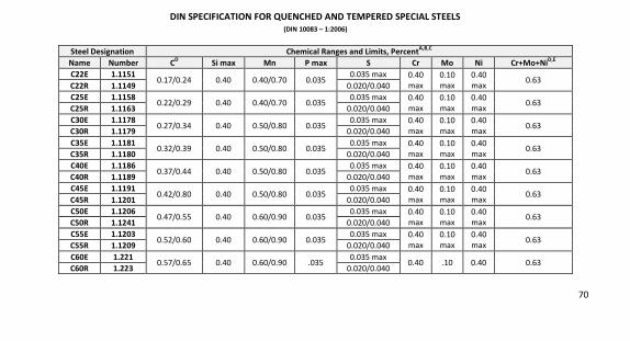
70
DIN SPECIFICATION FOR QUENCHED AND TEMPERED SPECIAL STEELS (DIN 10083 – 1:2006)
Steel Designation Chemical Ranges and Limits, PercentA,B,C
Name Number CD Si max Mn P max S Cr Mo Ni Cr+Mo+NiD,E
C22E 1.1151 0.17/0.24 0.40 0.40/0.70 0.035
0.035 max 0.40
max
0.10
max
0.40
max 0.63
C22R 1.1149 0.020/0.040
C25E 1.1158 0.22/0.29 0.40 0.40/0.70 0.035
0.035 max 0.40
max
0.10
max
0.40
max 0.63
C25R 1.1163 0.020/0.040
C30E 1.1178 0.27/0.34 0.40 0.50/0.80 0.035
0.035 max 0.40
max
0.10
max
0.40
max 0.63
C30R 1.1179 0.020/0.040
C35E 1.1181 0.32/0.39 0.40 0.50/0.80 0.035
0.035 max 0.40
max
0.10
max
0.40
max 0.63
C35R 1.1180 0.020/0.040
C40E 1.1186 0.37/0.44 0.40 0.50/0.80 0.035
0.035 max 0.40
max
0.10
max
0.40
max 0.63
C40R 1.1189 0.020/0.040
C45E 1.1191 0.42/0.80 0.40 0.50/0.80 0.035
0.035 max 0.40
max
0.10
max
0.40
max 0.63
C45R 1.1201 0.020/0.040
C50E 1.1206 0.47/0.55 0.40 0.60/0.90 0.035
0.035 max 0.40
max
0.10
max
0.40
max 0.63
C50R 1.1241 0.020/0.040
C55E 1.1203 0.52/0.60 0.40 0.60/0.90 0.035
0.035 max 0.40
max
0.10
max
0.40
max 0.63
C55R 1.1209 0.020/0.040
C60E 1.221 0.57/0.65 0.40 0.60/0.90 .035
0.035 max 0.40 .10 0.40 0.63
C60R 1.223 0.020/0.040
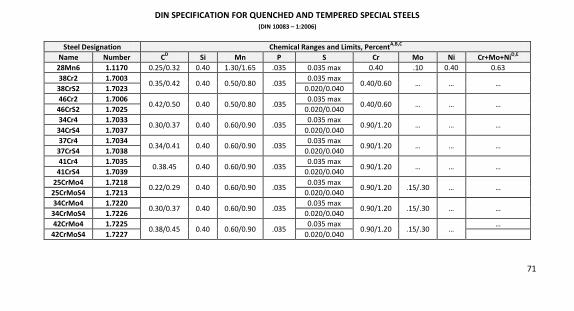
71
DIN SPECIFICATION FOR QUENCHED AND TEMPERED SPECIAL STEELS (DIN 10083 – 1:2006)
Steel Designation Chemical Ranges and Limits, PercentA,B,C
Name Number CD Si Mn P S Cr Mo Ni Cr+Mo+NiD,E
28Mn6 1.1170 0.25/0.32 0.40 1.30/1.65 .035 0.035 max 0.40 .10 0.40 0.63
38Cr2 1.7003 0.35/0.42 0.40 0.50/0.80 .035
0.035 max 0.40/0.60 … … …
38CrS2 1.7023 0.020/0.040
46Cr2 1.7006 0.42/0.50 0.40 0.50/0.80 .035
0.035 max 0.40/0.60 … … …
46CrS2 1.7025 0.020/0.040
34Cr4 1.7033 0.30/0.37 0.40 0.60/0.90 .035
0.035 max 0.90/1.20 … … …
34CrS4 1.7037 0.020/0.040
37Cr4 1.7034 0.34/0.41 0.40 0.60/0.90 .035
0.035 max 0.90/1.20 … … …
37CrS4 1.7038 0.020/0.040
41Cr4 1.7035 0.38.45 0.40 0.60/0.90 .035
0.035 max 0.90/1.20 … … …
41CrS4 1.7039 0.020/0.040
25CrMo4 1.7218 0.22/0.29 0.40 0.60/0.90 .035
0.035 max 0.90/1.20 .15/.30 … …
25CrMoS4 1.7213 0.020/0.040
34CrMo4 1.7220 0.30/0.37 0.40 0.60/0.90 .035
0.035 max 0.90/1.20 .15/.30 … …
34CrMoS4 1.7226 0.020/0.040
42CrMo4 1.7225 0.38/0.45 0.40 0.60/0.90 .035
0.035 max 0.90/1.20 .15/.30 …
…
42CrMoS4 1.7227 0.020/0.040
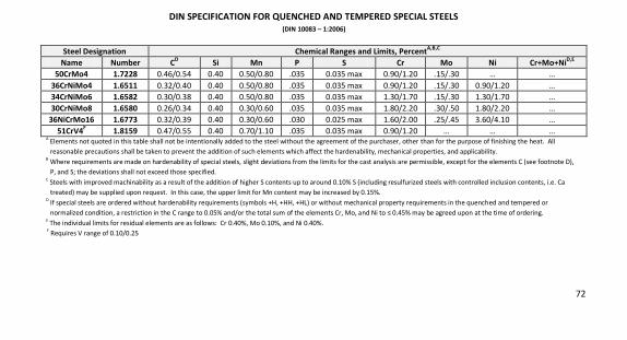
72
DIN SPECIFICATION FOR QUENCHED AND TEMPERED SPECIAL STEELS (DIN 10083 – 1:2006)
Steel Designation Chemical Ranges and Limits, PercentA,B,C
Name Number CD Si Mn P S Cr Mo Ni Cr+Mo+NiD,E
50CrMo4 1.7228 0.46/0.54 0.40 0.50/0.80 .035 0.035 max 0.90/1.20 .15/.30 … …
36CrNiMo4 1.6511 0.32/0.40 0.40 0.50/0.80 .035 0.035 max 0.90/1.20 .15/.30 0.90/1.20 …
34CrNiMo6 1.6582 0.30/0.38 0.40 0.50/0.80 .035 0.035 max 1.30/1.70 .15/.30 1.30/1.70 …
30CrNiMo8 1.6580 0.26/0.34 0.40 0.30/0.60 .035 0.035 max 1.80/2.20 .30/.50 1.80/2.20 …
36NiCrMo16 1.6773 0.32/0.39 0.40 0.30/0.60 .030 0.025 max 1.60/2.00 .25/.45 3.60/4.10 …
51CrV4F 1.8159 0.47/0.55 0.40 0.70/1.10 .035 0.035 max 0.90/1.20 … … … A
Elements not quoted in this table shall not be intentionally added to the steel without the agreement of the purchaser, other than for the purpose of finishing the heat. All
reasonable precautions shall be taken to prevent the addition of such elements which affect the hardenability, mechanical properties, and applicability. B
Where requirements are made on hardenability of special steels, slight deviations from the limits for the cast analysis are permissible, except for the elements C (see footnote D),
P, and S; the deviations shall not exceed those specified. C
Steels with improved machinability as a result of the addition of higher S contents up to around 0.10% S (including resulfurized steels with controlled inclusion contents, i.e. Ca
treated) may be supplied upon request. In this case, the upper limit for Mn content may be increased by 0.15%. D
If special steels are ordered without hardenability requirements (symbols +H, +HH, +HL) or without mechanical property requirements in the quenched and tempered or
normalized condition, a restriction in the C range to 0.05% and/or the total sum of the elements Cr, Mo, and Ni to ≤ 0.45% may be agreed upon at the time of ordering. E
The individual limits for residual elements are as follows: Cr 0.40%, Mo 0.10%, and Ni 0.40%.
F Requires V range of 0.10/0.25
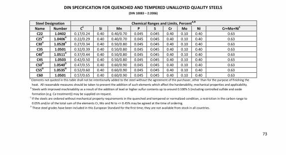
73
DIN SPECIFICATION FOR QUENCHED AND TEMPERED UNALLOYED QUALITY STEELS (DIN 10083 – 2:2006)
Steel Designation Chemical Ranges and Limits, PercentA,B
Name Number CC Si Mn P S Cr Mo Ni Cr+Mo+NiC C22 1.0402 0.17/0.24 0.40 0.40/0.70 0.045 0.045 0.40 0.10 0.40 0.63
C254 1.04064 0.22/0.29 0.40 0.40/0.70 0.045 0.045 0.40 0.10 0.40 0.63
C304 1.05284 0.27/0.34 0.40 0.50/0.80 0.045 0.045 0.40 0.10 0.40 0.63
C35 1.0501 0.32/0.39 0.40 0.50/0.80 0.045 0.045 0.40 0.10 0.40 0.63
C404 1.05114 0.37/0.44 0.40 0.50/0.80 0.045 0.045 0.40 0.10 0.40 0.63
C45 1.0503 0.42/0.50 0.40 0.50/0.80 0.045 0.045 0.40 0.10 0.40 0.63
C50D 1.0540D 0.47/0.55 0.40 0.60/0.90 0.045 0.045 0.40 0.10 0.40 0.63
C55D 1.0535D 0.52/0.60 0.40 0.60/0.90 0.045 0.045 0.40 0.10 0.40 0.63
C60 1.0501 0.57/0.65 0.40 0.60/0.90 0.045 0.045 0.40 0.10 0.40 0.63 A
Elements not quoted in this table shall not be intentionally added to the steel without the agreement of the purchaser, other than for the purpose of finishing the
heat. All reasonable measures should be taken to prevent the addition of such elements which affect the hardenability, mechanical properties and applicability.
B Steels with improved machinability as a result of the addition of lead or higher sulfur contents up to around 0.100% S (including controlled sulfide and oxide
formation (e.g. Ca treatment)) may be supplied on request.
C If the steels are ordered without mechanical property requirements in the quenched and tempered or normalized condition, a restriction in the carbon range to
0.05% and/or of the total sum of the elements Cr, Mo and Ni to <= 0.45% may be agreed at the time of ordering.
D These steel grades have been included in this European Standard for the first time; they are not available from stock in all countries.
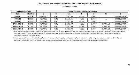
74
DIN SPECIFICATION FOR QUENCHED AND TEMPERED BORON STEELS (DIN 10083 – 3:2006)
Steel Designation Chemical Ranges and Limits, Percent Name Number C Si Mn P S Cr B
20MnB5 1.5530 0.17/0.23 0.40 1.10/1.40 0.035 0.040 … 0.0008/0.0050
30MnB5 1.5531 0.27/0.33 0.40 1.15/1.45 0.035 0.040 … 0.0008/0.0050
38MnB5 1.5532 0.36/0.42 0.40 1.15/1.45 0.035 0.040 … 0.0008/0.0050
27MnCrB5-2 1.7182 0.24/0.30 0.40 1.10/1.40 0.035 0.040 0.30/0.60 0.0008/0.0050
33MnCrB5-2 1.7185 0.30/0.36 0.40 1.20/1.50 0.035 0.040 0.30/0.60 0.0008/0.0050
39MnCrB6-2 1.7189 0.36/0.42 0.40 1.40/1.70 0.035 0.040 0.30/0.60 0.0008/0.0050
A Elements not listed in this table should not be intentionally added to the steel without the agreement of the purchaser other than for the purpose of finishing the cast and
For boron to have its effect on the hardenability. All reasonable precautions shall be taken to prevent the addition of such elements which affect the hardenability,
Mechanical properties and applicability.
B When requirements are made on hardenability or on the mechanical properties in the quenched and tempered condition, slight deviations from the limits on the cast
Analysis are permissible except for the elements carbon, phosphorous and sulfur; the deviations shall not exceed the values given in DIN 10083.
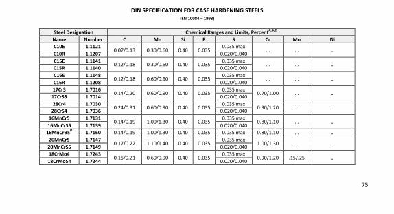
75
DIN SPECIFICATION FOR CASE HARDENING STEELS (EN 10084 – 1998)
Steel Designation Chemical Ranges and Limits, PercentA,B,C
Name Number C Mn Si P S Cr Mo Ni C10E 1.1121
0.07/0.13 0.30/0.60 0.40 0.035 0.035 max
... ... ... C10R 1.1207 0.020/0.040
C15E 1.1141 0.12/0.18 0.30/0.60 0.40 0.035
0.035 max ... ... ...
C15R 1.1140 0.020/0.040
C16E 1.1148 0.12/0.18 0.60/0.90 0.40 0.035
0.035 max ... ... ...
C16R 1.1208 0.020/0.040
17Cr3 1.7016 0.14/0.20 0.60/0.90 0.40 0.035
0.035 max 0.70/1.00 ... ...
17CrS3 1.7014 0.020/0.040
28Cr4 1.7030 0.24/0.31 0.60/0.90 0.40 0.035
0.035 max 0.90/1.20 ... ...
28CrS4 1.7036 0.020/0.040
16MnCr5 1.7131 0.14/0.19 1.00/1.30 0.40 0.035
0.035 max 0.80/1.10 ... ...
16MnCrS5 1.7139 0.020/0.040
16MnCrB5D 1.7160 0.14/0.19 1.00/1.30 0.40 0.035 0.035 max 0.80/1.10 ... ...
20MnCr5 1.7147 0.17/0.22 1.10/1.40 0.40 0.035
0.035 max 1.00/1.30 ... ...
20MnCrS5 1.7149 0.020/0.040
18CrMo4 1.7243 0.15/0.21 0.60/0.90 0.40 0.035
0.035 max 0.90/1.20 .15/.25 ...
18CrMoS4 1.7244 0.020/0.040
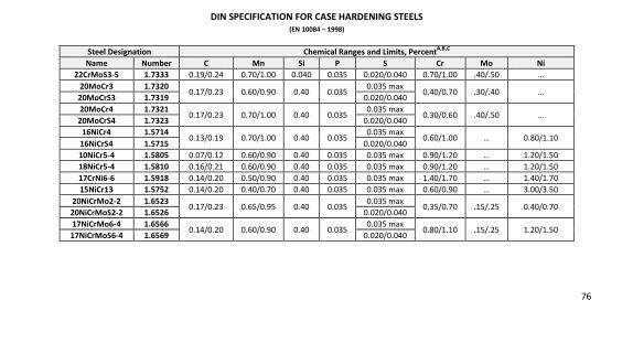
76
DIN SPECIFICATION FOR CASE HARDENING STEELS (EN 10084 – 1998)
Steel Designation Chemical Ranges and Limits, PercentA,B,C
Name Number C Mn Si P S Cr Mo Ni 22CrMoS3-5 1.7333 0.19/0.24 0.70/1.00 0.040 0.035 0.020/0.040 0.70/1.00 .40/.50 …
20MoCr3 1.7320 0.17/0.23 0.60/0.90 0.40 0.035
0.035 max 0.40/0.70 .30/.40 …
20MoCrS3 1.7319 0.020/0.040
20MoCr4 1.7321 0.17/0.23 0.70/1.00 0.40 0.035
0.035 max 0.30/0.60 .40/.50 …
20MoCrS4 1.7323 0.020/0.040
16NiCr4 1.5714 0.13/0.19 0.70/1.00 0.40 0.035
0.035 max 0.60/1.00 … 0.80/1.10
16NiCrS4 1.5715 0.020/0.040
10NiCr5-4 1.5805 0.07/0.12 0.60/0.90 0.40 0.035 0.035 max 0.90/1.20 … 1.20/1.50
18NiCr5-4 1.5810 0.16/0.21 0.60/0.90 0.40 0.035 0.035 max 0.90/1.20 … 1.20/1.50
17CrNi6-6 1.5918 0.14/0.20 0.50/0.90 0.40 0.035 0.035 max 1.40/1.70 … 1.40/1.70
15NiCr13 1.5752 0.14/0.20 0.40/0.70 0.40 0.035 0.035 max 0.60/0.90 … 3.00/3.50
20NiCrMo2-2 1.6523 0.17/0.23 0.65/0.95 0.40 0.035
0.035 max 0.35/0.70 .15/.25 0.40/0.70
20NiCrMoS2-2 1.6526 0.020/0.040
17NiCrMo6-4 1.6566 0.14/0.20 0.60/0.90 0.40 0.035
0.035 max 0.80/1.10 .15/.25 1.20/1.50
17NiCrMoS6-4 1.6569 0.020/0.040
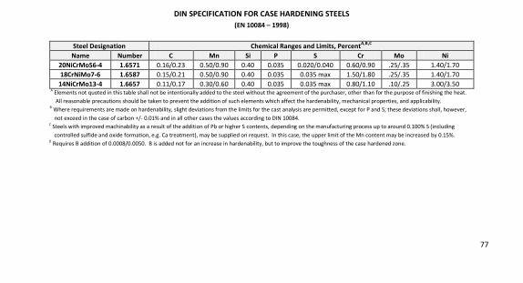
77
DIN SPECIFICATION FOR CASE HARDENING STEELS (EN 10084 – 1998)
Steel Designation Chemical Ranges and Limits, PercentA,B,C
Name Number C Mn Si P S Cr Mo Ni 20NiCrMoS6-4 1.6571 0.16/0.23 0.50/0.90 0.40 0.035 0.020/0.040 0.60/0.90 .25/.35 1.40/1.70
18CrNiMo7-6 1.6587 0.15/0.21 0.50/0.90 0.40 0.035 0.035 max 1.50/1.80 .25/.35 1.40/1.70
14NiCrMo13-4 1.6657 0.11/0.17 0.30/0.60 0.40 0.035 0.035 max 0.80/1.10 .10/.25 3.00/3.50 A
Elements not quoted in this table shall not be intentionally added to the steel without the agreement of the purchaser, other than for the purpose of finishing the heat.
All reasonable precautions should be taken to prevent the addition of such elements which affect the hardenability, mechanical properties, and applicability. B
Where requirements are made on hardenability, slight deviations from the limits for the cast analysis are permitted, except for P and S; these deviations shall, however,
not exceed in the case of carbon +/- 0.01% and in all other cases the values according to DIN 10084. C
Steels with improved machinability as a result of the addition of Pb or higher S contents, depending on the manufacturing process up to around 0.100% S (including
controlled sulfide and oxide formation, e.g. Ca treatment), may be supplied on request. In this case, the upper limit of the Mn content may be increased by 0.15%. D
Requires B addition of 0.0008/0.0050. B is added not for an increase in hardenability, but to improve the toughness of the case hardened zone.
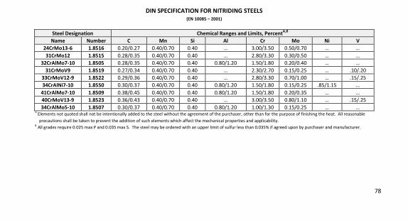
78
DIN SPECIFICATION FOR NITRIDING STEELS (EN 10085 – 2001)
Steel Designation Chemical Ranges and Limits, PercentA,B Name Number C Mn Si Al Cr Mo Ni V
24CrMo13-6 1.8516 0.20/0.27 0.40/0.70 0.40 … 3.00/3.50 0.50/0.70 … …
31CrMo12 1.8515 0.28/0.35 0.40/0.70 0.40 … 2.80/3.30 0.30/0.50 … …
32CrAlMo7-10 1.8505 0.28/0.35 0.40/0.70 0.40 0.80/1.20 1.50/1.80 0.20/0.40 … …
31CrMoV9 1.8519 0.27/0.34 0.40/0.70 0.40 … 2.30/2.70 0.15/0.25 … .10/.20
33CrMoV12-9 1.8522 0.29/0.36 0.40/0.70 0.40 … 2.80/3.30 0.70/1.00 … .15/.25
34CrAlNi7-10 1.8550 0.30/0.37 0.40/0.70 0.40 0.80/1.20 1.50/1.80 0.15/0.25 .85/1.15 …
41CrAlMo7-10 1.8509 0.38/0.45 0.40/0.70 0.40 0.80/1.20 1.50/1.80 0.20/0.35 … …
40CrMoV13-9 1.8523 0.36/0.43 0.40/0.70 0.40 … 3.00/3.50 0.80/1.10 … .15/.25
34CrAlMo5-10 1.8507 0.30/0.37 0.40/0.70 0.40 0.80/1.20 1.00/1.30 0.15/0.25 … … A
Elements not quoted shall not be intentionally added to the steel without the agreement of the purchaser, other than for the purpose of finishing the heat. All reasonable
precautions shall be taken to prevent the addition of such elements which affect the mechanical properties and applicability. B
All grades require 0.025 max P and 0.035 max S. The steel may be ordered with an upper limit of sulfur less than 0.035% if agreed upon by purchaser and manufacturer.
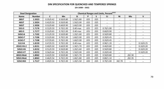
79
DIN SPECIFICATION FOR QUENCHED AND TEMPERED SPRINGS (EN 10089 – 2002)
Steel Designation Chemical Ranges and Limits, PercentA,B,C
Name Number C Mn Si P S Cr Ni Mo V 38Si7 1.5023 0.35/0.42 0.50/0.80 1.50/1.80 .025 .025 … … … …
46Si7 1.5024 0.42/0.50 0.50/0.80 1.50/2.00 .025 .025 … … … …
56Si7 1.5026 0.52/0.60 0.60/0.90 1.60/2.00 .025 .025 … … … …
55Cr3 1.7176 0.52/0.59 0.70/1.00 0.40 max .025 .025 0.70/1.00 … … …
60Cr3 1.7177 0.55/0.65 0.70/1.00 0.40 max .025 .025 0.60/0.90 … … …
54SiCr6 1.7102 0.51/0.59 0.50/0.80 1.20/1.60 .025 .025 0.50/0.80 … … …
56SiCr7 1.7106 0.52/0.60 0.70/1.00 1.60/2.00 .025 .025 0.20/0.45 … … …
61SiCr7 1.7108 0.57/0.65 0.70/1.00 1.60/2.00 .025 .025 0.20/0.45 … … …
51CrV4 1.8159 0.47/0.55 0.70/1.00 0.40 max .025 .025 0.90/1.20 … … 0.10/0.25
45SiCrV6-2 1.8151 0.40/0.50 0.60/0.90 1.30/1.70 .025 .025 0.40/0.80 … … 0.10/0.20
54SiCrV6 1.8152 0.51/0.59 0.50/0.80 1.20/1.60 .025 .025 0.50/0.80 … … 0.10/0.20
60SiCrV7 1.8153 0.56/0.64 0.70/1.00 1.50/2.00 .025 .025 0.20/0.40 … … 0.10/0.20
46SiCrMo6 1.8062 0.42/0.50 0.50/0.80 1.30/1.70 .025 .025 0.50/0.80 … .20/.30 …
50SiCrMo6 1.8063 0.46/0.54 0.70/1.00 1.40/1.80 .025 .025 0.80/1.10 … .20/.35 …
52SiCrNi5 1.7117 0.49/0.56 0.70/1.00 1.20/1.50 .025 .025 0.70/1.00 .50/.70 … …
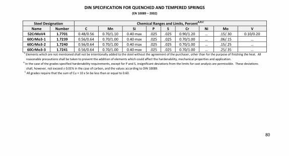
80
DIN SPECIFICATION FOR QUENCHED AND TEMPERED SPRINGS (EN 10089 – 2002)
Steel Designation Chemical Ranges and Limits, PercentA,B,C
Name Number C Mn Si P S Cr Ni Mo V 52CrMoV4 1.7701 0.48/0.56 0.70/1.10 0.40 max .025 .025 0.90/1.20 … .15/.30 0.10/0.20 60CrMo3-1 1.7239 0.56/0.64 0.70/1.00 0.40 max .025 .025 0.70/1.00 … .06/.15 … 60CrMo3-2 1.7240 0.56/0.64 0.70/1.00 0.40 max .025 .025 0.70/1.00 … .15/.25 … 60CrMo3-3 1.7241 0.56/0.64 0.70/1.00 0.40 max .025 .025 0.70/1.00 … .25/.35 …
A Elements which are not mentioned shall not be intentionally added to the steel without the agreement of the purchaser, other than for the purpose of finishing the heat. All
reasonable precautions shall be taken to prevent the addition of elements which could affect the hardenability, mechanical properties and application. B
In the case of the grades specified hardenability requirements, except for P and S, insignificant deviations from the limits for cast analysis are permissible. These deviations
shall, however, not exceed ± 0.01% in the case of carbon, and the values according to DIN 10089.
C All grades require that the sum of Cu + 10 x Sn be less than or equal to 0.60.
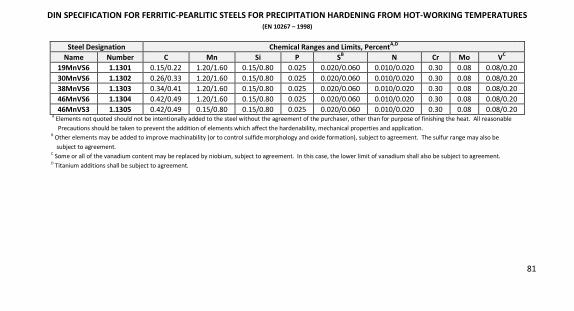
81
DIN SPECIFICATION FOR FERRITIC-PEARLITIC STEELS FOR PRECIPITATION HARDENING FROM HOT-WORKING TEMPERATURES (EN 10267 – 1998)
Steel Designation Chemical Ranges and Limits, PercentA,D
Name Number C Mn Si P SB N Cr Mo VC
19MnVS6 1.1301 0.15/0.22 1.20/1.60 0.15/0.80 0.025 0.020/0.060 0.010/0.020 0.30 0.08 0.08/0.20
30MnVS6 1.1302 0.26/0.33 1.20/1.60 0.15/0.80 0.025 0.020/0.060 0.010/0.020 0.30 0.08 0.08/0.20
38MnVS6 1.1303 0.34/0.41 1.20/1.60 0.15/0.80 0.025 0.020/0.060 0.010/0.020 0.30 0.08 0.08/0.20
46MnVS6 1.1304 0.42/0.49 1.20/1.60 0.15/0.80 0.025 0.020/0.060 0.010/0.020 0.30 0.08 0.08/0.20
46MnVS3 1.1305 0.42/0.49 0.15/0.80 0.15/0.80 0.025 0.020/0.060 0.010/0.020 0.30 0.08 0.08/0.20 A
Elements not quoted should not be intentionally added to the steel without the agreement of the purchaser, other than for purpose of finishing the heat. All reasonable
Precautions should be taken to prevent the addition of elements which affect the hardenability, mechanical properties and application. B
Other elements may be added to improve machinability (or to control sulfide morphology and oxide formation), subject to agreement. The sulfur range may also be
subject to agreement. C
Some or all of the vanadium content may be replaced by niobium, subject to agreement. In this case, the lower limit of vanadium shall also be subject to agreement. D
Titanium additions shall be subject to agreement.

82
NOTES
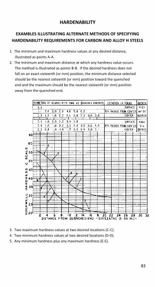
83
HARDENABILITY
EXAMBLES ILLUSTRATING ALTERNATE METHODS OF SPECIFYING HARDENABILITY REQUIREMENTS FOR CARBON AND ALLOY H STEELS
1. The minimum and maximum hardness values at any desired distance,
illustrated as points A-A.
2. The minimum and maximum distance at which any hardness value occurs.
The method is illustrated as points B-B. If the desired hardness does not
fall on an exact sixteenth (or mm) position, the minimum distance selected
should be the nearest sixteenth (or mm) position toward the quenched
end and the maximum should be the nearest sixteenth (or mm) position
away from the quenched end.
3. Two maximum hardness values at two desired locations (C-C).
4. Two minimum hardness values at two desired locations (D-D).
5. Any minimum hardness plus any maximum hardness (E-E).
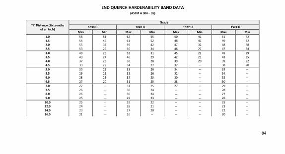
84
END QUENCH HARDENABILITY BAND DATA (ASTM A 304 – 05)
“J” Distance (Sixteenths of an inch)
Grade 1038 H 1045 H 1522 H 1524 H
Max Min Max Min Max Min Max Min 1.0 1.5 2.0 2.5
58
56
55
53
51
42
34
29
62
61
59
56
55
52
42
34
50
48
47
46
41
41
32
27
51
49
48
47
42
42
38
34
3.0 3.5 4.0 4.5
49
43 37
33
26
24 23
22
52
46 38
34
31
29 28
27
45
42 39
37
22
21 20
--
45
43 39
38
29
25 22
20
5.0 5.5 6.0 6.5
30
29
28
27
22
21
21
20
33
32
32
31
26
26
25
25
34
32
30
28
--
--
--
--
35
34
32
30
--
--
--
--
7.0 7.5 8.0 9.0
27
26
26
25
--
--
--
--
31
30
30
29
25
24
24
23
27
--
--
--
--
--
--
--
29
28
27
26
--
--
--
--
10.0 12.0 14.0 16.0
25 24
23
21
-- --
--
--
29 28
27
26
22 21
20
--
-- --
--
--
-- --
--
--
25 23
22
20
-- --
--
--
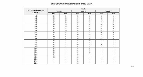
85
END QUENCH HARDENABILITY BAND DATA
“J” Distance (Sixteenths of an inch)
Grade 1526 H 1541 H 15B21 H
Max Min Max Min Max Min 1.0 1.5 2.0 2.5
53 50
49
47
44 42
38
33
60 59
59
58
53 52
50
47
48 48
47
47
41 41
40
39
3.0 3.5 4.0 4.5
46
42
39
37
26
25
21
20
57
56
55
53
44
41
38
35
46
45
44
42
38
36
30
23
5.0 5.5 6.0 6.5
33
31
30 28
--
--
-- --
52
50
48 46
32
29
27 26
40
38
35 32
20
--
-- --
7.0 7.5 8.0 9.0
27
26
26
24
--
--
--
--
44
41
39
35
25
24
23
22
27
22
20
--
--
--
--
--
10.0 12.0 14.0 16.0
24
23
22
21
--
--
--
--
33
32
31
30
22
21
20
--
--
--
--
--
--
--
--
--
18.0 20.0 24.0 28.0
20
-- --
--
--
-- --
--
30
29 28
26
--
-- --
--
--
-- --
--
--
-- --
--
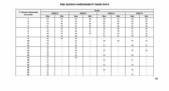
86
END QUENCH HARDENABILITY BAND DATA
“J” Distance (Sixteenths of an inch)
Grade 15B28 H 15B30 H 15B35 H 15B37 H
Max Min Max Min Max Min Max Min 1 2 3 4
53 53
52
51
47 47
46
45
55 53
52
51
48 47
46
44
58 56
55
54
51 50
49
48
58 56
55
54
50 50
49
48
5 6 7 8
51
50
49
48
42
32
25
21
50
48
43
38
32
22
20
--
53
51
47
41
39
28
24
22
53
52
51
50
43
37
33
26
9 10 11 12
46
43
40 37
20
--
-- --
33
29
27 26
--
--
-- --
--
30
-- 27
--
20
-- --
--
45
-- 40
--
22
-- 21
13 14 15 16
34
31
30
29
--
--
--
--
25
24
23
22
--
--
--
--
--
26
--
25
--
--
--
--
--
33
--
29
--
20
--
--
18 20 22 24
27
25
25
24
--
--
--
--
20
--
--
--
--
--
--
--
--
24
--
22
--
--
--
--
--
27
--
25
--
--
--
--
26 28 30 32
23
22 21
20
--
-- --
--
--
-- --
--
--
-- --
--
--
20 --
--
--
-- --
--
--
23 --
21
--
-- --
--
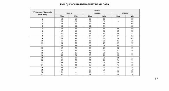
87
END QUENCH HARDENABILITY BAND DATA
“J” Distance (Sixteenths of an inch)
Grade 15B41 H 15B48 H 15B62H
Max Min Max Min Max Min 1 2 3 4
60 59
59
58
53 52
52
51
63 62
62
61
56 56
55
54
-- --
--
--
60 60
60
60
5 6 7 8
58
57
57
56
51
50
49
48
60
59
58
57
53
52
42
34
65
65
64
64
59
58
57
52
9 10 11 12
55
55
54 53
44
37
32 28
56
55
53 51
31
30
29 28
64
63
63 63
43
39
37 35
13 14 15 16
52
51
50
49
26
25
25
24
48
45
41
38
27
27
26
26
62
62
61
60
35
34
33
33
18 20 22 24
46
42
39
36
23
22
21
21
34
32
31
30
25
24
23
22
58
54
48
43
32
31
30
30
26 28 30 32
34
33 31
31
20
-- --
--
29
29 28
28
21
20 --
--
40
37 35
34
29
28 27
26
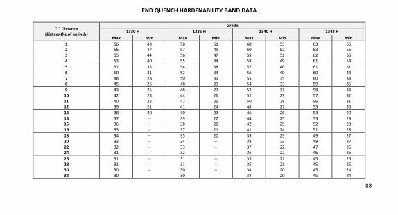
88
END QUENCH HARDENABILITY BAND DATA
“J” Distance (Sixteenths of an inch)
Grade 1330 H 1335 H 1340 H 1345 H
Max Min Max Min Max Min Max Min 1 2 3 4
56 56
55
53
49 47
44
40
58 57
56
55
51 49
47
44
60 60
59
58
53 52
51
49
63 63
62
61
56 56
55
54
5 6 7 8
52
50
48
45
35
31
28
26
54
52
50
48
38
34
31
29
57
56
55
54
46
40
35
33
61
60
60
59
51
44
38
35
9 10 11 12
43
42
40 39
25
23
22 21
46
44
42 41
27
26
25 24
52
51
50 48
31
29
28 27
58
57
56 55
33
32
31 30
13 14 15 16
38
37
36
35
20
--
--
--
40
39
38
37
23
22
22
21
46
44
42
41
26
25
25
24
54
53
52
51
29
29
28
28
18 20 22 24
34
33
32
31
--
--
--
--
35
34
33
32
20
--
--
--
39
38
37
36
23
23
22
22
49
48
47
46
27
27
26
26
26 28 30 32
31
31 30
30
--
-- --
--
31
31 30
30
--
-- --
--
35
35 34
34
21
21 20
20
45
45 45
45
25
25 24
24
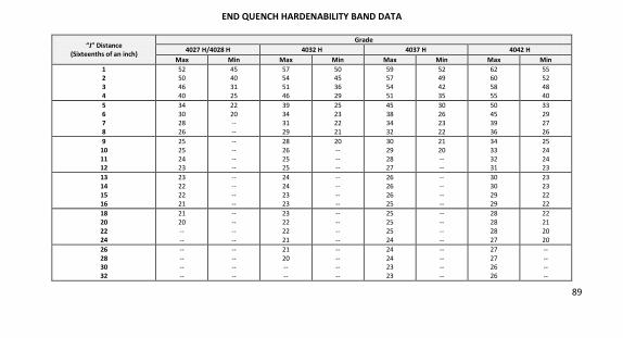
89
END QUENCH HARDENABILITY BAND DATA
“J” Distance (Sixteenths of an inch)
Grade 4027 H/4028 H 4032 H 4037 H 4042 H
Max Min Max Min Max Min Max Min 1 2 3 4
52 50
46
40
45 40
31
25
57 54
51
46
50 45
36
29
59 57
54
51
52 49
42
35
62 60
58
55
55 52
48
40
5 6 7 8
34
30
28
26
22
20
--
--
39
34
31
29
25
23
22
21
45
38
34
32
30
26
23
22
50
45
39
36
33
29
27
26
9 10 11 12
25
25
24 23
--
--
-- --
28
26
25 25
20
--
-- --
30
29
28 27
21
20
-- --
34
33
32 31
25
24
24 23
13 14 15 16
23
22
22
21
--
--
--
--
24
24
23
23
--
--
--
--
26
26
26
25
--
--
--
--
30
30
29
29
23
23
22
22
18 20 22 24
21
20
--
--
--
--
--
--
23
22
22
21
--
--
--
--
25
25
25
24
--
--
--
--
28
28
28
27
22
21
20
20
26 28 30 32
--
-- --
--
--
-- --
--
21
20 --
--
--
-- --
--
24
24 23
23
--
-- --
--
27
27 26
26
--
-- --
--
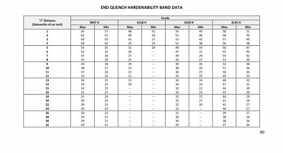
90
END QUENCH HARDENABILITY BAND DATA
“J” Distance (Sixteenths of an inch)
Grade 4047 H 4118 H 4130 H 4135 H
Max Min Max Min Max Min Max Min 1 2 3 4
64 62
60
58
57 55
50
42
48 46
41
35
41 36
27
23
56 55
53
51
49 46
42
38
58 58
57
56
51 50
49
48
5 6 7 8
55
52
47
43
35
32
30
28
31
28
27
25
20
--
--
--
49
47
44
42
34
31
29
27
56
55
54
53
47
45
42
40
9 10 11 12
40
38
37 35
28
27
26 26
24
23
22 21
--
--
-- --
40
38
36 35
26
26
25 25
52
51
50 49
38
36
34 33
13 14 15 16
34
33
33
32
25
25
25
25
21
20
--
--
--
--
--
--
34
34
33
33
24
24
23
23
48
47
46
45
32
31
30
30
18 20 22 24
31
30
30
30
24
24
23
23
--
--
--
--
--
--
--
--
32
32
32
31
22
21
20
--
44
42
41
40
29
28
27
27
26 28 30 32
30
29 29
29
22
22 21
21
--
-- --
--
--
-- --
--
31
30 30
29
--
-- --
--
39
38 38
37
27
26 26
26
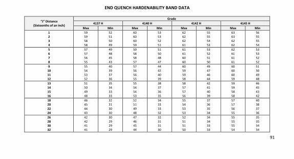
91
END QUENCH HARDENABILITY BAND DATA
“J” Distance (Sixteenths of an inch)
Grade 4137 H 4140 H 4142 H 4145 H
Max Min Max Min Max Min Max Min 1 2 3 4
59 59
58
58
52 51
50
49
60 60
60
59
53 53
52
51
62 62
62
61
55 55
54
53
63 63
62
62
56 55
55
54
5 6 7 8
57
57
56
55
49
48
45
43
59
58
58
57
51
50
48
47
61
61
60
60
53
52
51
50
62
61
61
61
53
53
52
52
9 10 11 12
55
54
53 52
40
39
37 36
57
56
56 55
44
42
40 39
60
59
59 58
49
47
46 44
60
60
60 59
51
50
49 48
13 14 15 16
51
50
49
48
35
34
33
33
55
54
54
53
38
37
36
35
58
57
57
56
42
41
40
39
59
59
58
58
46
45
43
42
18 20 22 24
46
45
44
43
32
31
30
30
52
51
49
48
34
33
33
32
55
54
53
53
37
36
35
34
57
57
56
55
40
38
37
36
26 28 30 32
42
42 41
41
30
29 29
29
47
46 45
44
32
31 31
30
52
51 51
50
34
34 33
33
55
55 55
54
35
35 34
34
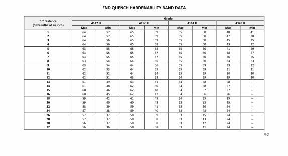
92
END QUENCH HARDENABILITY BAND DATA
“J” Distance (Sixteenths of an inch)
Grade 4147 H 4150 H 4161 H 4320 H
Max Min Max Min Max Min Max Min 1 2 3 4
64 64
64
64
57 57
56
56
65 65
65
65
59 59
59
58
65 65
65
65
60 60
60
60
48 47
45
43
41 38
35
32
5 6 7 8
63
63
63
63
55
55
55
54
65
65
65
64
58
57
57
56
65
65
65
65
60
60
60
60
41
38
36
34
29
27
25
23
9 10 11 12
63
62
62 62
54
53
52 51
64
64
64 63
56
55
54 53
65
65
65 64
59
59
59 59
33
31
30 29
22
21
20 20
13 14 15 16
61
61
60
60
49
48
46
45
63
62
62
62
51
50
48
47
64
64
64
64
58
58
57
56
28
27
27
26
--
--
--
--
18 20 22 24
59
59
58
57
42
40
39
38
61
60
59
59
45
43
41
40
64
63
63
63
55
53
50
48
25
25
24
24
--
--
--
--
26 28 30 32
57
57 56
56
37
37 37
36
58
58 58
58
39
38 38
38
63
63 63
63
45
43 42
41
24
24 24
24
--
-- --
--
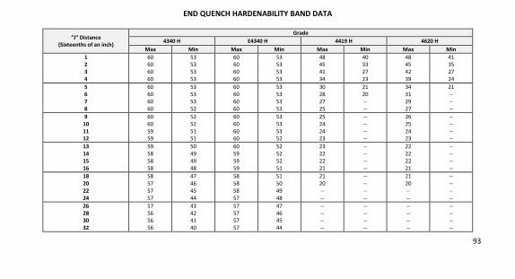
93
END QUENCH HARDENABILITY BAND DATA
“J” Distance (Sixteenths of an inch)
Grade 4340 H E4340 H 4419 H 4620 H
Max Min Max Min Max Min Max Min 1 2 3 4
60 60
60
60
53 53
53
53
60 60
60
60
53 53
53
53
48 45
41
34
40 33
27
23
48 45
42
39
41 35
27
24
5 6 7 8
60
60
60
60
53
53
53
52
60
60
60
60
53
53
53
53
30
28
27
25
21
20
--
--
34
31
29
27
21
--
--
--
9 10 11 12
60
60
59 59
52
52
51 51
60
60
60 60
53
53
53 52
25
24
24 23
--
--
-- --
26
25
24 23
--
--
-- --
13 14 15 16
59
58
58
58
50
49
49
48
60
59
59
59
52
52
52
51
23
22
22
21
--
--
--
--
22
22
22
21
--
--
--
--
18 20 22 24
58
57
57
57
47
46
45
44
58
58
58
57
51
50
49
48
21
20
--
--
--
--
--
--
21
20
--
--
--
--
--
--
26 28 30 32
57
56 56
56
43
42 41
40
57
57 57
57
47
46 45
44
--
-- --
--
--
-- --
--
--
-- --
--
--
-- --
--
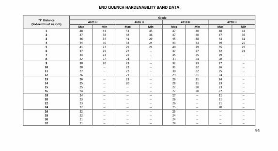
94
END QUENCH HARDENABILITY BAND DATA
“J” Distance (Sixteenths of an inch)
Grade 4621 H 4626 H 4718 H 4720 H
Max Min Max Min Max Min Max Min 1 2 3 4
48 47
46
44
41 38
34
30
51 48
41
33
45 36
29
24
47 47
45
43
40 40
38
33
48 47
43
39
41 39
31
27
5 6 7 8
41
37
34
32
27
25
23
22
29
27
25
24
21
--
--
--
40
37
35
33
29
27
25
24
35
32
29
28
23
21
--
--
9 10 11 12
30
28
27 26
20
--
-- --
23
22
22 21
--
--
-- --
32
31
30 29
23
22
22 21
27
26
25 24
--
--
-- --
13 14 15 16
26
25
25
24
--
--
--
--
21
20
--
--
--
--
--
--
29
28
27
27
21
21
20
20
24
23
23
22
--
--
--
--
18 20 22 24
24
23
23
22
--
--
--
--
--
--
--
--
--
--
--
--
27
26
26
25
--
--
--
--
21
21
21
20
--
--
--
--
26 28 30 32
22
22 21
21
--
-- --
--
--
-- --
--
--
-- --
--
25
24 24
24
--
-- --
--
--
-- --
--
--
-- --
--
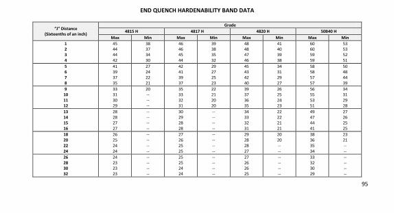
95
END QUENCH HARDENABILITY BAND DATA
“J” Distance (Sixteenths of an inch)
Grade 4815 H 4817 H 4820 H 50B40 H
Max Min Max Min Max Min Max Min 1 2 3 4
45 44
44
42
38 37
34
30
46 46
45
44
39 38
35
32
48 48
47
46
41 40
39
38
60 60
59
59
53 53
52
51
5 6 7 8
41
39
37
35
27
24
22
21
42
41
39
37
29
27
25
23
45
43
42
40
34
31
29
27
58
58
57
57
50
48
44
39
9 10 11 12
33
31
30 29
20
--
-- --
35
33
32 31
22
21
20 20
39
37
36 35
26
25
24 23
56
55
53 51
34
31
29 28
13 14 15 16
28
28
27
27
--
--
--
--
30
29
28
28
--
--
--
--
34
33
32
31
22
22
21
21
49
47
44
41
27
26
25
25
18 20 22 24
26
25
24
24
--
--
--
--
27
26
25
25
--
--
--
--
29
28
28
27
20
20
--
--
38
36
35
34
23
21
--
--
26 28 30 32
24
23 23
23
--
-- --
--
25
25 24
24
--
-- --
--
27
26 26
25
--
-- --
--
33
32 30
29
--
-- --
--
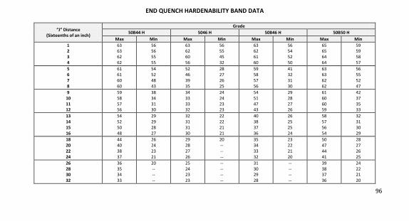
96
END QUENCH HARDENABILITY BAND DATA
“J” Distance (Sixteenths of an inch)
Grade 50B44 H 5046 H 50B46 H 50B50 H
Max Min Max Min Max Min Max Min 1 2 3 4
63 63
62
62
56 56
55
55
63 62
60
56
56 55
45
32
63 62
61
60
56 54
52
50
65 65
64
64
59 59
58
57
5 6 7 8
61
61
60
60
54
52
48
43
52
46
39
35
28
27
26
25
59
58
57
56
41
32
31
30
63
63
62
62
56
55
52
47
9 10 11 12
59
58
57 56
38
34
31 30
34
33
33 32
24
24
23 23
54
51
47 43
29
28
27 26
61
60
60 59
42
37
35 33
13 14 15 16
54
52
50
48
29
29
28
27
32
31
31
30
22
22
21
21
40
38
37
36
26
25
25
24
58
57
56
54
32
31
30
29
18 20 22 24
44
40
38
37
26
24
23
21
29
28
27
26
20
--
--
--
35
34
33
32
23
22
21
20
50
47
44
41
28
27
26
25
26 28 30 32
36
35 34
33
20
-- --
--
25
24 23
23
--
-- --
--
31
30 29
28
--
-- --
--
39
38 37
36
24
22 21
20
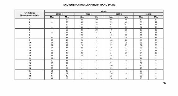
97
END QUENCH HARDENABILITY BAND DATA
“J” Distance (Sixteenths of an inch)
Grade 50B60 H 5120 H 5130 H 5132 H
Max Min Max Min Max Min Max Min 1 2 3 4
-- --
--
--
60 60
60
60
48 46
41
36
40 34
28
23
56 55
53
51
49 46
42
39
57 56
54
52
50 47
43
40
5 6 7 8
--
--
--
65
60
59
57
53
33
30
28
27
20
--
--
--
49
47
45
42
35
32
30
28
50
48
45
42
35
32
29
27
9 10 11 12
65
64
64 64
47
42
39 37
25
24
23 22
--
--
-- --
40
38
37 36
26
25
23 22
40
38
37 36
25
24
23 22
13 14 15 16
63
63
63
62
36
35
34
34
21
21
20
--
--
--
--
--
35
34
34
33
21
20
--
--
35
34
34
33
21
20
--
--
18 20 22 24
60
58
55
53
33
31
30
29
--
--
--
--
--
--
--
--
32
31
30
29
--
--
--
--
32
31
30
29
--
--
--
--
26 28 30 32
51
49 47
44
28
27 26
25
--
-- --
--
--
-- --
--
27
26 25
24
--
-- --
--
28
27 26
25
--
-- --
--
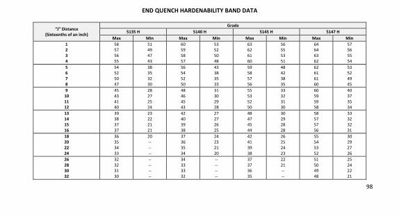
98
END QUENCH HARDENABILITY BAND DATA
“J” Distance (Sixteenths of an inch)
Grade 5135 H 5140 H 5145 H 5147 H
Max Min Max Min Max Min Max Min 1 2 3 4
58 57
56
55
51 49
47
43
60 59
58
57
53 52
50
48
63 62
61
60
56 55
53
51
64 64
63
62
57 56
55
54
5 6 7 8
54
52
50
47
38
35
32
30
56
54
52
50
43
38
35
33
59
58
57
56
48
42
38
35
62
61
61
60
53
52
49
45
9 10 11 12
45
43
41 40
28
27
25 24
48
46
45 43
31
30
29 28
55
53
52 50
33
32
31 30
60
59
59 58
40
37
35 34
13 14 15 16
39
38
37
37
23
22
21
21
42
40
39
38
27
27
26
25
48
47
45
44
30
29
28
28
58
57
57
56
33
32
32
31
18 20 22 24
36
35
34
33
20
--
--
--
37
36
35
34
24
23
21
20
42
41
39
38
26
25
24
23
55
54
53
52
30
29
27
26
26 28 30 32
32
32 31
30
--
-- --
--
34
33 33
32
--
-- --
--
37
37 36
35
22
21 --
--
51
50 49
48
25
24 22
21
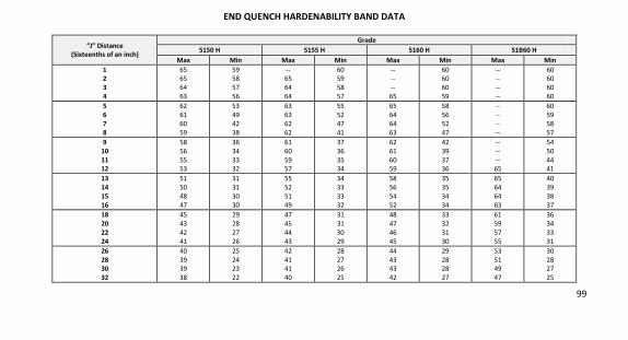
99
END QUENCH HARDENABILITY BAND DATA
“J” Distance (Sixteenths of an inch)
Grade 5150 H 5155 H 5160 H 51B60 H
Max Min Max Min Max Min Max Min 1 2 3 4
65 65
64
63
59 58
57
56
-- 65
64
64
60 59
58
57
-- --
--
65
60 60
60
59
-- --
--
--
60 60
60
60
5 6 7 8
62
61
60
59
53
49
42
38
63
63
62
62
55
52
47
41
65
64
64
63
58
56
52
47
--
--
--
--
60
59
58
57
9 10 11 12
58
56
55 53
36
34
33 32
61
60
59 57
37
36
35 34
62
61
60 59
42
39
37 36
--
--
-- 65
54
50
44 41
13 14 15 16
51
50
48
47
31
31
30
30
55
52
51
49
34
33
33
32
58
56
54
52
35
35
34
34
65
64
64
63
40
39
38
37
18 20 22 24
45
43
42
41
29
28
27
26
47
45
44
43
31
31
30
29
48
47
46
45
33
32
31
30
61
59
57
55
36
34
33
31
26 28 30 32
40
39 39
38
25
24 23
22
42
41 41
40
28
27 26
25
44
43 43
42
29
28 28
27
53
51 49
47
30
28 27
25
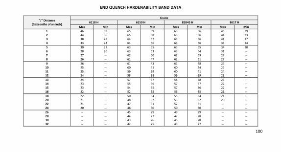
100
END QUENCH HARDENABILITY BAND DATA
“J” Distance (Sixteenths of an inch)
Grade 6118 H 6150 H 81B45 H 8617 H
Max Min Max Min Max Min Max Min 1 2 3 4
46 44
38
33
39 36
28
24
65 65
64
64
59 58
57
56
63 63
63
63
56 56
56
56
46 44
41
38
39 33
27
24
5 6 7 8
30
28
27
26
22
20
--
--
63
63
62
61
55
53
50
47
63
63
62
62
55
54
53
51
34
31
28
27
20
--
--
--
9 10 11 12
26
25
25 24
--
--
-- --
61
60
59 58
43
41
39 38
61
60
60 59
48
44
41 39
26
25
24 23
--
--
-- --
13 14 15 16
24
23
23
22
--
--
--
--
57
55
54
52
37
36
35
35
58
57
57
56
38
37
36
35
23
22
22
21
--
--
--
--
18 20 22 24
22
21
21
20
--
--
--
--
50
48
47
46
34
32
31
30
55
53
52
50
34
32
31
30
21
20
--
--
--
--
--
--
26 28 30 32
--
-- --
--
--
-- --
--
45
44 43
42
29
27 26
25
49
47 45
43
29
28 28
27
--
-- --
--
--
-- --
--
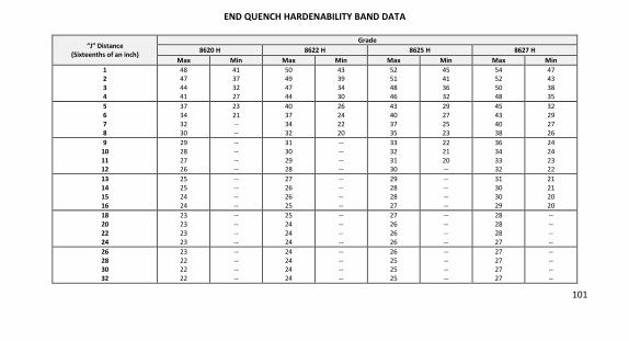
101
END QUENCH HARDENABILITY BAND DATA
“J” Distance (Sixteenths of an inch)
Grade 8620 H 8622 H 8625 H 8627 H
Max Min Max Min Max Min Max Min 1 2 3 4
48 47
44
41
41 37
32
27
50 49
47
44
43 39
34
30
52 51
48
46
45 41
36
32
54 52
50
48
47 43
38
35
5 6 7 8
37
34
32
30
23
21
--
--
40
37
34
32
26
24
22
20
43
40
37
35
29
27
25
23
45
43
40
38
32
29
27
26
9 10 11 12
29
28
27 26
--
--
-- --
31
30
29 28
--
--
-- --
33
32
31 30
22
21
20 --
36
34
33 32
24
24
23 22
13 14 15 16
25
25
24
24
--
--
--
--
27
26
26
25
--
--
--
--
29
28
28
27
--
--
--
--
31
30
30
29
21
21
20
20
18 20 22 24
23
23
23
23
--
--
--
--
25
24
24
24
--
--
--
--
27
26
26
26
--
--
--
--
28
28
28
27
--
--
--
--
26 28 30 32
23
22 22
22
--
-- --
--
24
24 24
24
--
-- --
--
26
25 25
25
--
-- --
--
27
27 27
27
--
-- --
--
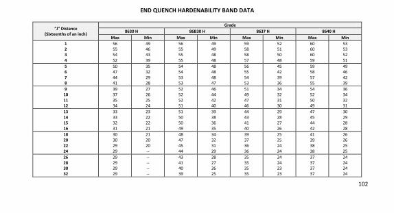
102
END QUENCH HARDENABILITY BAND DATA
“J” Distance (Sixteenths of an inch)
Grade 8630 H 86B30 H 8637 H 8640 H
Max Min Max Min Max Min Max Min 1 2 3 4
56 55
54
52
49 46
43
39
56 55
55
55
49 49
48
48
59 58
58
57
52 51
50
48
60 60
60
59
53 53
52
51
5 6 7 8
50
47
44
41
35
32
29
28
54
54
53
53
48
48
48
47
56
55
54
53
45
42
39
36
59
58
57
55
49
46
42
39
9 10 11 12
39
37
35 34
27
26
25 24
52
52
52 51
46
44
42 40
51
49
47 46
34
32
31 30
54
52
50 49
36
34
32 31
13 14 15 16
33
33
32
31
23
22
22
21
51
50
50
49
39
38
36
35
44
43
41
40
29
28
27
26
47
45
44
42
30
29
28
28
18 20 22 24
30
30
29
29
21
20
20
--
48
47
45
44
34
32
31
29
39
37
36
36
25
25
24
24
41
39
38
38
26
26
25
25
26 28 30 32
29
29 29
29
--
-- --
--
43
41 40
39
28
27 26
25
35
35 35
35
24
24 23
23
37
37 37
37
24
24 24
24
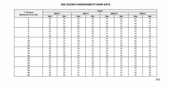
103
END QUENCH HARDENABILITY BAND DATA
“J” Distance (Sixteenths of an inch)
Grade 8642 H 8645 H 86B45 H 8650 H
Max Min Max Min Max Min Max Min 1 2 3 4
62 62
62
61
55 54
53
52
63 63
63
63
56 56
55
54
63 63
62
62
56 56
55
54
65 65
65
64
59 58
57
57
5 6 7 8
61
60
59
58
50
48
45
42
62
61
61
60
52
50
48
45
62
61
61
60
54
53
52
52
64
63
63
62
56
54
53
50
9 10 11 12
57
55
54 52
39
37
34 33
59
58
56 55
41
39
37 35
60
60
59 59
51
51
50 50
61
60
60 59
47
44
41 39
13 14 15 16
50
49
48
46
32
31
30
29
54
52
51
49
34
33
32
31
59
59
58
58
49
48
46
45
58
58
57
56
37
36
35
34
18 20 22 24
44
42
41
40
28
28
27
27
47
45
43
42
30
29
28
28
58
58
57
57
42
39
37
35
55
53
52
50
33
32
31
31
26 28 30 32
40
39 39
39
26
26 26
26
42
41 41
41
27
27 27
27
57
57 56
56
34
32 32
31
49
47 46
45
30
30 29
29
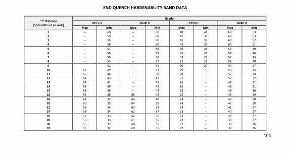
104
END QUENCH HARDENABILITY BAND DATA
“J” Distance (Sixteenths of an inch)
Grade 8655 H 8660 H 8720 H 8740 H
Max Min Max Min Max Min Max Min 1 2 3 4
-- --
--
--
60 59
59
58
-- --
--
--
60 60
60
60
48 47
45
42
41 38
35
30
60 60
60
60
53 53
52
51
5 6 7 8
--
--
--
--
57
56
55
54
--
--
--
--
60
59
58
57
39
35
33
31
26
24
22
21
59
58
57
56
49
46
43
40
9 10 11 12
--
65
65 64
52
49
46 43
--
--
-- --
55
53
50 47
30
29
28 27
20
--
-- --
55
53
52 50
37
35
34 32
13 14 15 16
64
63
63
62
41
40
39
38
--
--
--
65
45
44
43
42
26
26
25
25
--
--
--
--
49
48
46
45
31
31
30
29
18 20 22 24
61
60
59
58
37
35
34
34
64
64
63
62
40
39
38
37
24
24
23
23
--
--
--
--
43
42
41
40
28
28
27
27
26 28 30 32
57
56 55
53
33
33 32
32
62
61 60
60
36
36 35
35
23
23 22
22
--
-- --
--
39
39 38
38
27
27 26
26

105
END QUENCH HARDENABILITY BAND DATA
“J” Distance (Sixteenths of an inch)
Grade 8822 H 9260 H 9310 H 94B15 H
Max Min Max Min Max Min Max Min 1 2 3 4
50 49
48
46
43 42
39
33
-- --
65
64
60 60
57
53
43 43
43
42
36 35
35
34
45 45
44
44
38 38
37
36
5 6 7 8
43
40
37
35
29
27
25
24
63
62
60
58
46
41
38
36
42
42
42
41
32
31
30
29
43
42
40
38
32
28
25
23
9 10 11 12
34
33
32 31
24
23
23 22
55
52
49 47
36
35
34 34
40
40
39 38
28
27
27 26
36
34
33 31
21
20
-- --
13 14 15 16
31
30
30
29
22
22
21
21
45
43
42
40
33
33
32
32
37
36
36
35
26
26
26
26
30
29
28
27
--
--
--
--
18 20 22 24
29
28
27
27
20
--
--
--
38
37
36
36
31
31
30
30
35
35
34
34
26
25
25
25
26
25
24
23
--
--
--
--
26 28 30 32
27
27 27
27
--
-- --
--
35
35 35
34
29
29 28
28
34
34 33
33
25
25 24
24
23
22 22
22
--
-- --
--
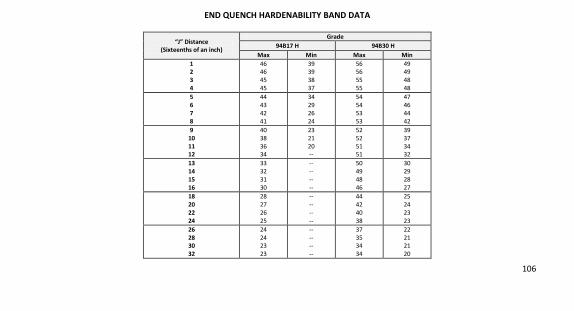
106
END QUENCH HARDENABILITY BAND DATA
“J” Distance (Sixteenths of an inch)
Grade 94B17 H 94B30 H
Max Min Max Min 1 2 3 4
46 46
45
45
39 39
38
37
56 56
55
55
49 49
48
48
5 6 7 8
44
43
42
41
34
29
26
24
54
54
53
53
47
46
44
42
9 10 11 12
40
38
36 34
23
21
20 --
52
52
51 51
39
37
34 32
13 14 15 16
33
32
31
30
--
--
--
--
50
49
48
46
30
29
28
27
18 20 22 24
28
27
26
25
--
--
--
--
44
42
40
38
25
24
23
23
26 28 30 32
24
24 23
23
--
-- --
--
37
35 34
34
22
21 21
20
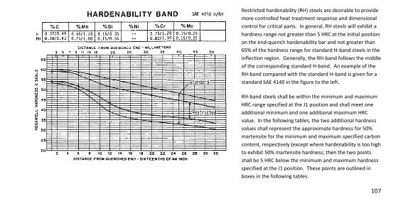
107
Restricted hardenability (RH) steels are desirable to provide
more controlled heat treatment response and dimensional
control for critical parts. In general, RH steels will exhibit a
hardness range not greater than 5 HRC at the initial position
on the end-quench hardenability bar and not greater than
65% of the hardness range for standard H-band steels in the
inflection region. Generally, the RH-band follows the middle
of the corresponding standard H-band. An example of the
RH-band compared with the standard H-band is given for a
standard SAE 4140 in the figure to the left.
RH-band steels shall be within the minimum and maximum
HRC range specified at the J1 position and shall meet one
additional minimum and one additional maximum HRC
value. In the following tables, the two additional hardness
values shall represent the approximate hardness for 50%
martensite for the minimum and maximum specified carbon
content, respectively (except where hardenability is too high
to exhibit 50% martensite hardness; then the two points
shall be 5 HRC below the minimum and maximum hardness
specified at the J1 position. These points are outlined in
boxes in the following tables.
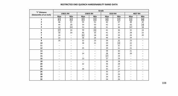
108
RESTRICTED END QUENCH HARDENABILITY BAND DATA
“J” Distance (Sixteenths of an inch)
Grade 15B21 RH 15B35 RH 3310 RH 4027 RH
Max Min Max Min Max Min Max Min 1 2 3 4
47
46
44
42
42
41
39
33
57
55
54
53
52
51
50
49
42
42
42
41
37
37
37
36
51
48
43
37
46
42
34
28
5 6 7 8
37
30
24
22
24
20
--
--
50
46
42
36
41
33
28
24
41
41
40
40
36
35
34
33
32
28
26
24
24
22
20
--
9 10 11 12
20
-- --
--
--
-- --
--
32
28 --
25
23
21 --
--
39
39 39
39
32
32
31 31
23
22 22
21
--
-- --
--
13 14 15 16
-- --
--
--
-- --
--
--
-- 24
--
23
-- --
--
--
38
38
37
37
30 30
29
29
21 20
--
--
-- --
--
--
18 20 22 24
--
--
--
--
--
--
--
--
--
22
--
20
--
--
--
--
36
36
35
35
28
28
27
27
--
--
--
--
--
--
--
--
26 28 30 32
--
--
--
--
--
--
--
--
--
--
--
--
--
--
--
--
35
34
34
34
27
26
26
26
--
--
--
--
--
--
--
--
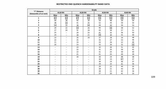
109
RESTRICTED END QUENCH HARDENABILITY BAND DATA
“J” Distance (Sixteenths of an inch)
Grade 4118 RH 4120 RH 4130 RH 4140 RH
Max Min Max Min Max Min Max Min 1 2 3 4
47
44
38
33
42
38
30
25
47
45
41
38
42
39
35
30
55
54
52
49
50
48
44
40
59
59
59
59
54
54
54
53
5 6 7 8
29
27
25
24
22
20
--
--
34
31
29
28
26
24
22
21
46
44
41
39
36
34
32
30
58
57
56
55
52
51
50
49
9 10 11 12
23
22 21
20
--
-- --
--
26
25 24
23
20
-- --
--
37
35 33
32
28
27 26
26
54
53 52
52
48
46 44
43
13 14 15 16
-- --
--
--
-- --
--
--
23 22
22
21
-- --
--
--
32 31
31
31
26 25
25
25
51 50
50
49
42 41
40
39
18 20 22 24
-- --
--
--
-- --
--
--
20 --
--
--
-- --
--
--
30 30
30
29
24 23
23
22
48
47
46
45
38 37
37
36
26 28 30 32
--
--
--
--
--
--
--
--
--
--
--
--
--
--
--
--
29
28
28
27
22
21
21
20
44
43
42
41
35
35
34
33
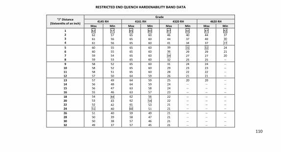
110
RESTRICTED END QUENCH HARDENABILITY BAND DATA
“J” Distance (Sixteenths of an inch)
Grade 4145 RH 4161 RH 4320 RH 4620 RH
Max Min Max Min Max Min Max Min 1 2 3 4
62
62
61
61
57
57
56
56
65
65
65
65
60
60
60
60
47
46
44
41
42
40
37
34
47
44
40
37
42
37
30
27
5 6 7 8
60
60
59
59
55
55
54
53
65
65
65
65
60
60
60
60
39
36
34
32
31
29
27
25
32
29
27
25
24
21
20
--
9 10 11 12
58
58 58
57
52
52 51
50
65
65 65
64
60
60 60
59
31
29 28
26
24
23 22
21
24
23 22
21
--
-- --
--
13 14 15 16
57
56
56
55
49
48
47
46
64
64
63
63
59
59
58
57
25
24
24
23
20
--
--
--
20
--
--
--
--
--
--
--
18 20 22 24
54
53
52
51
44
43
42
40
62
62
61
60
56
54
53
51
22
22
21
21
--
--
--
--
--
--
--
--
--
--
--
--
26 28 30 32
51
50
50
49
40
39
38
37
59
58
57
57
49
47
46
45
21
21
21
21
--
--
--
--
--
--
--
--
--
--
--
--
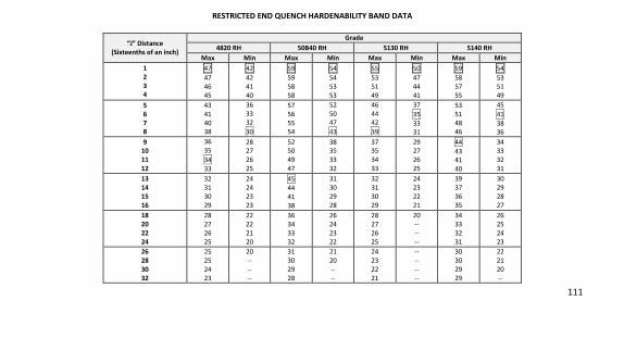
111
RESTRICTED END QUENCH HARDENABILITY BAND DATA
“J” Distance (Sixteenths of an inch)
Grade 4820 RH 50B40 RH 5130 RH 5140 RH
Max Min Max Min Max Min Max Min 1 2 3 4
47
47
46
45
42
42
41
40
59
59
58
58
54
54
53
53
55
53
51
49
50
47
44
41
59
58
57
55
54
53
51
49
5 6 7 8
43
41
40 38
36
33 32
30
57
56
55 54
52
50 47
43
46
44 42
39
37
35
33 31
53
51
48 46
45
41
38 36
9 10 11 12
36
35
34
33
28 27
26
25
52 50
49
47
38 35
33
32
37 35
34
33
29 27
26
25
44
43 41
40
34 33
32
31
13 14 15 16
32
31
30
29
24
24
23
23
45
44
41
38
31
30
29
28
32
31
30
29
24
23
22
21
39
37
36
35
30
29
28
27
18 20 22 24
28
27
26
25
22
22
21
20
36
34
33
32
26
24
23
22
28
27
26
25
20
--
--
--
34
33
32
31
26
25
24
23
26 28 30 32
25
25
24
23
20
--
--
--
31
30
29
28
21
20
--
--
24
23
22
21
--
--
--
--
30
30
29
29
22
21
20
--
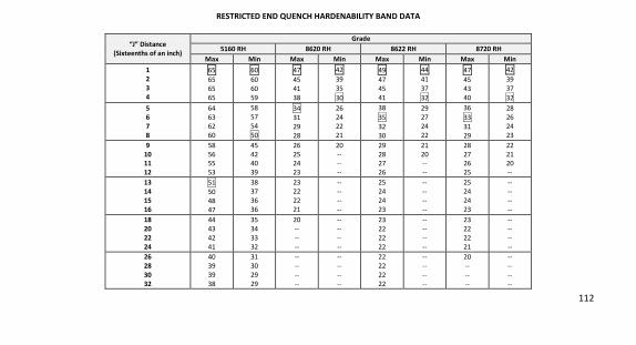
112
RESTRICTED END QUENCH HARDENABILITY BAND DATA
“J” Distance (Sixteenths of an inch)
Grade 5160 RH 8620 RH 8622 RH 8720 RH
Max Min Max Min Max Min Max Min 1 2 3 4
65
65
65
65
60
60
60
59
47
45
41
38
42
39
35
30
49
47
45
41
44
41
37
32
47
45
43
40
42
39
37
32
5 6 7 8
64
63
62
60
58
57
54
50
34
31
29
28
26
24
22
21
38
35
32
30
29
27
24
22
36
33
31
29
28
26
24
23
9 10 11 12
58
56 55
53
45
42 40
39
26
25 24
23
20
-- --
--
29
28 27
26
21
20 --
--
28
27 26
25
22
21 20
--
13 14 15 16
51
50
48
47
38
37
36
36
23
22
22
21
--
--
--
--
25
24
24
23
--
--
--
--
25
24
24
23
--
--
--
--
18 20 22 24
44
43
42
41
35
34
33
32
20
--
--
--
--
--
--
--
23
22
22
22
--
--
--
--
23
22
22
21
--
--
--
--
26 28 30 32
40
39
39
38
31
30
29
29
--
--
--
--
--
--
--
--
22
22
22
22
--
--
--
--
20
--
--
--
--
--
--
--
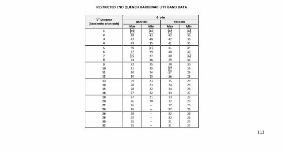
113
RESTRICTED END QUENCH HARDENABILITY BAND DATA
“J” Distance (Sixteenths of an inch)
Grade 8822 RH 9310 RH
Max Min Max Min 1 2 3 4
49
48
47
43
44
43
40
35
42
42
42
41
37
36
36
35
5 6 7 8
40
37
35
33
31
29
27
26
41
40
40 39
34
33
32
31
9 10 11 12
32
31 30
30
25
25 24
23
38
37
37
36
30
29 29
28
13 14 15 16
29
28
28
27
23
23
22
22
35
34
34
33
28
28
28
27
18 20 22 24
27
26
26
26
21
20
--
--
33
32
32
32
27
26
26
26
26 28 30 32
26 25
25
25
-- --
--
--
32 32
31
31
26 26
25
25
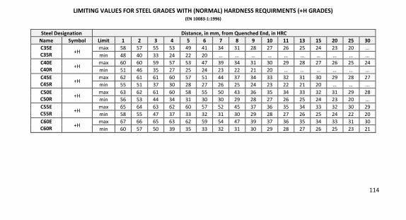
114
LIMITING VALUES FOR STEEL GRADES WITH (NORMAL) HARDNESS REQUIRMENTS (+H GRADES) (EN 10083-1:1996)
Steel Designation Distance, in mm, from Quenched End, in HRC Name Symbol Limit 1 2 3 4 5 6 7 8 9 10 11 13 15 20 25 30 C35E C35R +H
max 58 57 55 53 49 41 34 31 28 27 26 25 24 23 20 …
min 48 40 33 24 22 20 … … … … … … … … … …
C40E C40R +H
max 60 60 59 57 53 47 39 34 31 30 29 28 27 26 25 24
min 51 46 35 27 25 24 23 22 21 20 … … … … … …
C45E C45R +H
max 62 61 61 60 57 51 44 37 34 33 32 31 30 29 28 27
min 55 51 37 30 28 27 26 25 24 23 22 21 20 … … …
C50E C50R +H
max 63 62 61 60 58 55 50 43 36 35 34 33 32 31 29 28
min 56 53 44 34 31 30 30 29 28 27 26 25 24 23 20 …
C55E C55R +H
max 65 64 63 62 60 57 52 45 37 36 35 34 33 32 30 29
min 58 55 47 37 33 32 31 30 29 28 27 26 25 24 22 20
C60E C60R +H
max 67 66 65 63 62 59 54 47 39 37 36 35 34 33 31 30
min 60 57 50 39 35 33 32 31 30 29 28 27 26 25 23 21
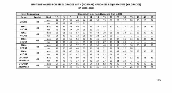
115
LIMITING VALUES FOR STEEL GRADES WITH (NORMAL) HARDNESS REQUIRMENTS (+H GRADES) (EN 10083-1:1996)
Steel Designation Distance, in mm, from Quenched End, in HRC Name Symbol Limit 1.5 3 5 7 9 11 13 15 20 25 30 35 40 45 50
28Mn6 +H max 54 53 51 48 44 41 38 35 31 29 27 26 25 25 24
min 45 42 37 27 21 … … … … … … … … … …
38Cr2 38CrS2 +H
max 59 57 54 49 43 39 37 35 32 30 27 25 24 23 22
min 51 46 37 29 25 22 20 … … … … … … … …
46Cr2 46CrS2 +H
max 63 61 59 57 53 47 42 39 36 33 32 31 30 29 29
min 54 49 40 32 28 25 23 22 20 … … … … … …
34Cr4 34CrS4 +H
max 57 57 56 54 52 49 46 44 39 37 35 34 33 32 31
min 49 48 45 41 35 32 29 27 23 21 20 … … … …
37Cr4 37CrS4 +H
max 59 59 58 57 55 52 50 48 42 39 37 36 35 34 33
min 51 50 48 44 39 36 33 31 26 24 22 20 … … …
41Cr4 41CrS4 +H
max 61 61 60 59 58 56 54 52 46 42 40 38 37 36 35
min 53 52 50 47 41 37 34 32 29 26 23 21 … … …
25CrMo4 25CrMoS4 +H
max 52 52 51 50 48 46 43 41 37 35 33 32 31 31 31
min 44 43 40 37 34 32 29 27 23 21 20 … … … …
34CrMo4 34CrMoS4 +H
max 57 57 57 56 55 54 53 52 48 45 43 41 40 40 39
min 49 49 48 45 42 39 36 34 30 28 27 26 25 24 24
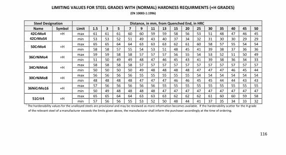
116
LIMITING VALUES FOR STEEL GRADES WITH (NORMAL) HARDNESS REQUIRMENTS (+H GRADES) (EN 10083-1:1996)
Steel Designation Distance, in mm, from Quenched End, in HRC Name Symbol Limit 1.5 3 5 7 9 11 13 15 20 25 30 35 40 45 50
42CrMo4 42CrMoS4
+H max 61 61 61 60 60 59 59 58 56 53 51 48 47 46 45
min 53 53 52 51 49 43 40 37 34 32 31 30 30 29 29
50CrMo4 +H max 65 65 64 64 63 63 63 62 61 60 58 57 55 54 54
min 58 58 57 55 54 53 51 48 45 41 39 38 37 36 36
36CrNiMo4 +H max 59 59 58 58 57 57 57 56 55 54 53 52 51 50 49
min 51 50 49 49 48 47 46 45 43 41 39 38 36 34 33
34CrNiMo6 +H max 58 58 58 58 57 57 57 57 57 57 57 57 57 57 57
min 50 50 50 50 49 48 48 48 48 47 47 47 46 45 44
30CrNiMo8 +H max 56 56 56 56 55 55 55 55 55 54 54 54 54 54 54
min 48 48 48 48 47 47 47 46 46 45 45 44 44 43 43
36NiCrMo16 +H max 57 56 56 56 56 56 55 55 55 55 55 55 55 55 55
min 50 49 48 48 48 48 47 47 47 47 47 47 47 47 47
51CrV4 +H max 65 65 64 64 63 63 63 62 62 62 61 60 60 59 58
min 57 56 56 55 53 52 50 48 44 41 37 35 34 33 32 1
The hardenability values for the unalloyed steels are provisional and may be reviewed as more information becomes available. If the hardenability scatter for the H grade
of the relevant steel of a manufacturer exceeds the limits given above, the manufacturer shall inform the purchaser accordingly at the time of ordering.
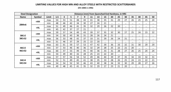
117
LIMITING VALUES FOR HIGH MN AND ALLOY STEELS WITH RESTRICTED SCATTERBANDS (EN 10083-1:1996)
Steel Designation Distance (mm) from Quenched End Hardness, in HRC Name Symbol Limit 1.5 3 5 7 9 11 13 15 20 25 30 35 40 45 50
28Mn6 +HH
max 54 53 51 48 44 41 38 35 31 29 27 26 25 25 24
min 48 46 42 34 30 27 24 21 … … … … … … …
+HL max 51 49 46 41 35 32 29 26 22 20 … … … … …
min 45 42 37 27 21 … … … … … … … … … …
38Cr2 38CrS2
+HH max 59 57 54 49 43 39 37 35 32 30 27 25 24 23 22
min 54 50 43 36 31 28 26 24 21 … … … … … …
+HL max 56 53 48 42 37 33 31 29 26 24 21 … … … …
min 51 46 37 29 25 22 20 … … … … … … … …
46Cr2 46CrS2
+HH max 63 61 59 57 53 47 42 39 36 33 32 31 30 29 29
min 57 53 46 40 36 32 29 28 25 22 21 20 … … …
+HL max 60 57 53 49 45 40 36 33 31 28 27 26 25 24 24
min 54 49 40 32 28 25 23 22 20 … … … … … …
34Cr4 34CrS4
+HH max 57 57 56 54 52 49 46 44 39 37 35 34 33 32 31
min 52 51 49 45 41 38 35 33 28 26 25 24 23 22 21
+HL max 54 54 52 50 46 43 40 38 34 32 30 29 28 27 26
min 49 48 45 41 35 32 29 27 23 21 20 … … … …
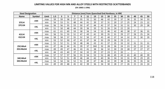
118
LIMITING VALUES FOR HIGH MN AND ALLOY STEELS WITH RESTRICTED SCATTERBANDS (EN 10083-1:1996)
Steel Designation Distance (mm) from Quenched End Hardness, in HRC Name Symbol Limit 1.5 3 5 7 9 11 13 15 20 25 30 35 40 45 50
37Cr4 37CrS4
+HH max 59 59 58 57 55 52 50 48 42 39 37 36 35 34 33
min 54 53 51 48 44 41 39 37 31 29 27 25 24 23 22
+HL max 56 56 55 53 50 47 44 42 37 34 32 31 30 29 28
min 51 50 48 44 39 36 33 31 26 24 22 20 … … …
41Cr4 41CrS4
+HH max 61 61 60 59 58 56 54 52 46 42 40 38 37 36 35
min 56 55 53 51 47 43 41 39 35 31 29 27 26 25 24
+HL max 58 58 57 55 52 50 47 45 40 37 34 32 31 30 29
min 53 52 50 47 41 37 34 32 29 26 23 21 … … …
25CrMo4 25CrMoS4
+HH max 52 52 51 50 48 46 43 41 37 35 33 32 31 31 31
min 47 46 44 41 39 37 344 32 28 26 24 23 22 22 22
+HL max 49 49 47 46 43 41 38 36 32 30 29 28 27 27 27
min 44 43 40 37 34 32 29 27 23 21 20 … … … …
34CrMo4 34CrMoS4
+HH max 57 57 57 56 55 54 53 52 48 45 43 41 40 40 39
min 52 52 51 49 46 44 42 40 36 34 32 31 30 29 29
+HL max 54 54 54 52 51 49 47 46 42 39 38 36 35 35 34
min 49 49 48 45 42 39 36 34 30 28 27 26 25 24 24
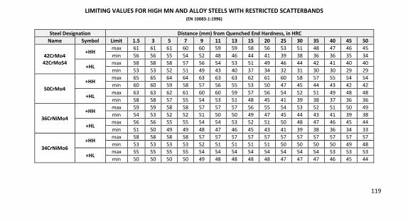
119
LIMITING VALUES FOR HIGH MN AND ALLOY STEELS WITH RESTRICTED SCATTERBANDS (EN 10083-1:1996)
Steel Designation Distance (mm) from Quenched End Hardness, in HRC Name Symbol Limit 1.5 3 5 7 9 11 13 15 20 25 30 35 40 45 50
42CrMo4 42CrMoS4
+HH max 61 61 61 60 60 59 59 58 56 53 51 48 47 46 45
min 56 56 55 54 52 48 46 44 41 39 38 36 36 35 34
+HL max 58 58 58 57 56 54 53 51 49 46 44 42 41 40 40
min 53 53 52 51 49 43 40 37 34 32 31 30 30 29 29
50CrMo4 +HH
max 65 65 64 64 63 63 63 62 61 60 58 57 55 54 54
min 60 60 59 58 57 56 55 53 50 47 45 44 43 42 42
+HL max 63 63 62 61 60 60 59 57 56 54 52 51 49 48 48
min 58 58 57 55 54 53 51 48 45 41 39 38 37 36 36
36CrNiMo4 +HH
max 59 59 58 58 57 57 57 56 55 54 53 52 51 50 49
min 54 53 52 52 51 50 50 49 47 45 44 43 41 39 38
+HL max 56 56 55 55 54 54 53 52 51 50 48 47 46 45 44
min 51 50 49 49 48 47 46 45 43 41 39 38 36 34 33
34CrNiMo6 +HH
max 58 58 58 58 57 57 57 57 57 57 57 57 57 57 57
min 53 53 53 53 52 51 51 51 51 50 50 50 50 49 48
+HL max 55 55 55 55 54 54 54 54 54 54 54 54 53 53 53
min 50 50 50 50 49 48 48 48 48 47 47 47 46 45 44
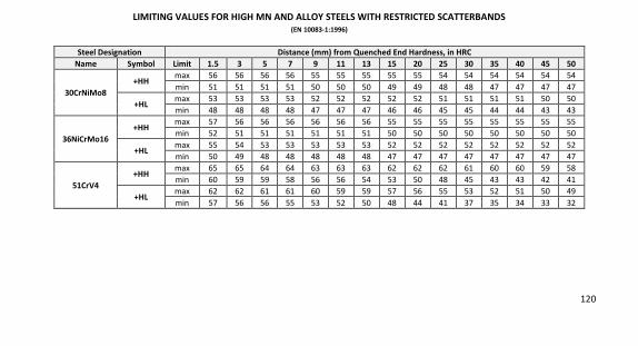
120
LIMITING VALUES FOR HIGH MN AND ALLOY STEELS WITH RESTRICTED SCATTERBANDS (EN 10083-1:1996)
Steel Designation Distance (mm) from Quenched End Hardness, in HRC Name Symbol Limit 1.5 3 5 7 9 11 13 15 20 25 30 35 40 45 50
30CrNiMo8 +HH
max 56 56 56 56 55 55 55 55 55 54 54 54 54 54 54
min 51 51 51 51 50 50 50 49 49 48 48 47 47 47 47
+HL max 53 53 53 53 52 52 52 52 52 51 51 51 51 50 50
min 48 48 48 48 47 47 47 46 46 45 45 44 44 43 43
36NiCrMo16 +HH
max 57 56 56 56 56 56 56 55 55 55 55 55 55 55 55
min 52 51 51 51 51 51 51 50 50 50 50 50 50 50 50
+HL max 55 54 53 53 53 53 53 52 52 52 52 52 52 52 52
min 50 49 48 48 48 48 48 47 47 47 47 47 47 47 47
51CrV4 +HH
max 65 65 64 64 63 63 63 62 62 62 61 60 60 59 58
min 60 59 59 58 56 56 54 53 50 48 45 43 43 42 41
+HL max 62 62 61 61 60 59 59 57 56 55 53 52 51 50 49
min 57 56 56 55 53 52 50 48 44 41 37 35 34 33 32
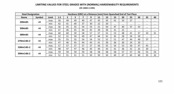
121
LIMITING VALUES FOR STEEL GRADES WITH (NORMAL) HARDENABILITY REQUIREMENTS (EN 10083-3:1995)
Steel Designation Hardness (HRC) at a Distance (mm) from Quenched End of Test Piece Name Symbol Limit 1.5 3 5 7 9 11 13 15 20 25 30 35 40
20MnB5 +H max 50 49 49 49 47 45 43 41 33 27 … … …
min 42 41 40 37 30 22 20 … … … … … …
30MnB5 +H max 56 55 55 54 53 51 50 47 40 37 33 … …
min 47 46 45 44 42 39 36 31 22 … … … …
38MnB5 +H max 60 60 59 58 57 57 55 53 48 41 37 33 31
min 52 51 50 49 47 44 41 35 28 24 20 … …
27MnCrB5-2 +H max 55 55 55 54 54 53 52 51 47 44 40 37 …
min 47 46 45 44 43 41 39 36 30 24 20 … …
33MnCrB5-2 +H max 57 57 57 57 57 56 55 54 53 50 47 45 …
min 48 47 47 46 45 44 43 41 36 31 25 20 …
39MnCrB6-2 +H max 59 59 59 59 58 58 58 58 57 57 56 55 54
min 51 51 51 51 50 50 50 49 47 45 40 35 32
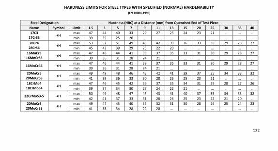
122
HARDNESS LIMITS FOR STEEL TYPES WITH SPECIFIED (NORMAL) HARDENABILITY (EN 10084-1998)
Steel Designation Hardness (HRC) at a Distance (mm) from Quenched End of Test Piece Name Symbol Limit 1.5 3 5 7 9 11 13 15 20 25 30 35 40 17C3
17CrS3 +H max 47 44 40 33 29 27 25 24 23 21 … … …
min 39 35 25 20 … … … … … … … … …
28Cr4 28CrS4 +H
max 53 52 51 49 45 42 39 36 33 30 29 28 27
min 45 43 39 29 25 22 20 … … … … … …
16MnCr5 16MnCrS5 +H
max 47 46 44 41 39 37 35 33 31 30 29 28 27
min 39 36 31 28 24 21 … … … … … … …
16MnCrB5 +H max 47 46 44 41 39 37 35 33 31 30 29 28 27
min 39 36 31 28 24 21 … … … … … … …
20MnCr5 20MnCr5S +H
max 49 49 48 46 43 42 41 39 37 35 34 33 32
min 41 39 36 33 30 28 26 25 23 21 … … …
18CrMo4 18CrMoS4 +H
max 47 46 45 42 39 37 35 34 31 29 28 27 26
min 39 37 34 30 27 24 22 21 … … … … …
22CrMoS3-5 +H max 50 49 48 47 45 43 41 40 37 35 34 33 32
min 42 41 37 33 31 28 26 25 23 22 21 20 …
20MoCr3 20MoCrS3 +H
max 49 47 45 40 35 32 31 30 28 26 25 24 23
min 41 38 34 28 22 20 … … … … … … …
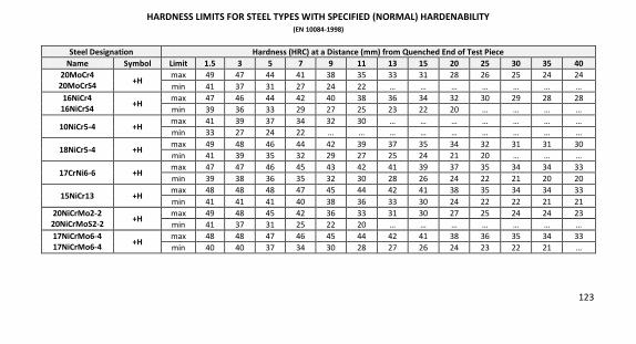
123
HARDNESS LIMITS FOR STEEL TYPES WITH SPECIFIED (NORMAL) HARDENABILITY (EN 10084-1998)
Steel Designation Hardness (HRC) at a Distance (mm) from Quenched End of Test Piece Name Symbol Limit 1.5 3 5 7 9 11 13 15 20 25 30 35 40
20MoCr4 20MoCrS4 +H
max 49 47 44 41 38 35 33 31 28 26 25 24 24
min 41 37 31 27 24 22 … … … … … … …
16NiCr4 16NiCrS4 +H
max 47 46 44 42 40 38 36 34 32 30 29 28 28
min 39 36 33 29 27 25 23 22 20 … … … …
10NiCr5-4 +H max 41 39 37 34 32 30 … … … … … … …
min 33 27 24 22 … … … … … … … … …
18NiCr5-4 +H max 49 48 46 44 42 39 37 35 34 32 31 31 30
min 41 39 35 32 29 27 25 24 21 20 … … …
17CrNi6-6 +H max 47 47 46 45 43 42 41 39 37 35 34 34 33
min 39 38 36 35 32 30 28 26 24 22 21 20 20
15NiCr13 +H max 48 48 48 47 45 44 42 41 38 35 34 34 33
min 41 41 41 40 38 36 33 30 24 22 22 21 21
20NiCrMo2-2 20NiCrMoS2-2 +H
max 49 48 45 42 36 33 31 30 27 25 24 24 23
min 41 37 31 25 22 20 … … … … … … …
17NiCrMo6-4 17NiCrMo6-4 +H
max 48 48 47 46 45 44 42 41 38 36 35 34 33
min 40 40 37 34 30 28 27 26 24 23 22 21 …
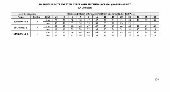
124
HARDNESS LIMITS FOR STEEL TYPES WITH SPECIFIED (NORMAL) HARDENABILITY (EN 10084-1998)
Steel Designation Hardness (HRC) at a Distance (mm) from Quenched End of Test Piece Name Symbol Limit 1.5 3 5 7 9 11 13 15 20 25 30 35 40
20NiCrMoS6-4 +H max 49 49 48 48 47 47 46 44 41 39 38 37 36
min 41 40 39 36 33 30 28 26 23 21 … … …
18CrNiMo7-6 +H max 48 48 48 48 47 47 46 46 44 43 42 41 41
min 40 40 39 38 37 36 35 34 32 31 30 29 29
14NiCrMo13-4 +H max 47 47 46 46 46 46 46 45 43 42 40 39 38
min 39 39 37 36 36 36 35 33 31 30 28 27 26
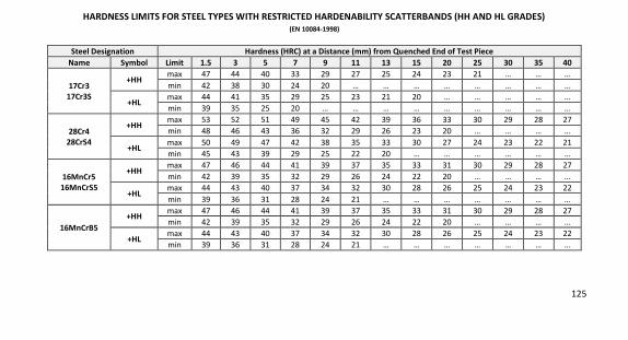
125
HARDNESS LIMITS FOR STEEL TYPES WITH RESTRICTED HARDENABILITY SCATTERBANDS (HH AND HL GRADES) (EN 10084-1998)
Steel Designation Hardness (HRC) at a Distance (mm) from Quenched End of Test Piece Name Symbol Limit 1.5 3 5 7 9 11 13 15 20 25 30 35 40
17Cr3 17Cr3S
+HH max 47 44 40 33 29 27 25 24 23 21 … … …
min 42 38 30 24 20 … … … … … … … …
+HL max 44 41 35 29 25 23 21 20 … … … … …
min 39 35 25 20 … … … … … … … … …
28Cr4 28CrS4
+HH max 53 52 51 49 45 42 39 36 33 30 29 28 27
min 48 46 43 36 32 29 26 23 20 … … … …
+HL max 50 49 47 42 38 35 33 30 27 24 23 22 21
min 45 43 39 29 25 22 20 … … … … … …
16MnCr5 16MnCrS5
+HH max 47 46 44 41 39 37 35 33 31 30 29 28 27
min 42 39 35 32 29 26 24 22 20 … … … …
+HL max 44 43 40 37 34 32 30 28 26 25 24 23 22
min 39 36 31 28 24 21 … … … … … … …
16MnCrB5 +HH
max 47 46 44 41 39 37 35 33 31 30 29 28 27
min 42 39 35 32 29 26 24 22 20 … … … …
+HL max 44 43 40 37 34 32 30 28 26 25 24 23 22
min 39 36 31 28 24 21 … … … … … … …
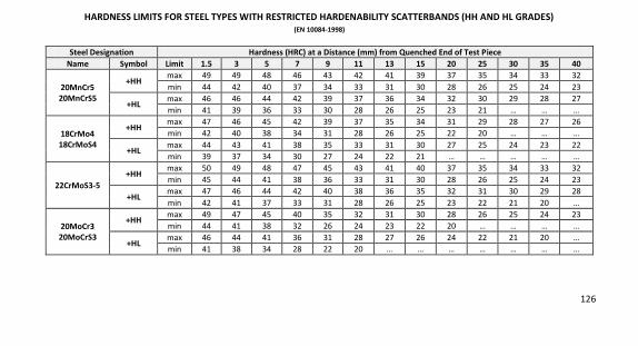
126
HARDNESS LIMITS FOR STEEL TYPES WITH RESTRICTED HARDENABILITY SCATTERBANDS (HH AND HL GRADES) (EN 10084-1998)
Steel Designation Hardness (HRC) at a Distance (mm) from Quenched End of Test Piece Name Symbol Limit 1.5 3 5 7 9 11 13 15 20 25 30 35 40
20MnCr5 20MnCrS5
+HH max 49 49 48 46 43 42 41 39 37 35 34 33 32
min 44 42 40 37 34 33 31 30 28 26 25 24 23
+HL max 46 46 44 42 39 37 36 34 32 30 29 28 27
min 41 39 36 33 30 28 26 25 23 21 … … …
18CrMo4 18CrMoS4
+HH max 47 46 45 42 39 37 35 34 31 29 28 27 26
min 42 40 38 34 31 28 26 25 22 20 … … …
+HL max 44 43 41 38 35 33 31 30 27 25 24 23 22
min 39 37 34 30 27 24 22 21 … … … … …
22CrMoS3-5 +HH
max 50 49 48 47 45 43 41 40 37 35 34 33 32
min 45 44 41 38 36 33 31 30 28 26 25 24 23
+HL max 47 46 44 42 40 38 36 35 32 31 30 29 28
min 42 41 37 33 31 28 26 25 23 22 21 20 …
20MoCr3 20MoCrS3
+HH max 49 47 45 40 35 32 31 30 28 26 25 24 23
min 44 41 38 32 26 24 23 22 20 … … … …
+HL max 46 44 41 36 31 28 27 26 24 22 21 20 …
min 41 38 34 28 22 20 … … … … … … …
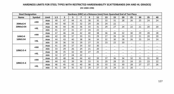
127
HARDNESS LIMITS FOR STEEL TYPES WITH RESTRICTED HARDENABILITY SCATTERBANDS (HH AND HL GRADES) (EN 10084-1998)
Steel Designation Hardness (HRC) at a Distance (mm) from Quenched End of Test Piece Name Symbol Limit 1.5 3 5 7 9 11 13 15 20 25 30 35 40
20MoCr4 20MoCrS4
+HH max 49 47 44 41 38 35 33 31 28 26 25 24 24
min 44 40 35 32 29 26 24 22 … … … … …
+HL max 46 44 40 36 33 31 29 27 24 22 21 20 20
min 41 37 31 27 24 22 … … … … … … …
16NiCr4 16NiCrS4
+HH max 47 46 44 42 40 38 36 34 32 30 29 28 28
min 42 39 37 33 31 29 27 26 24 22 21 20 20
+HL max 44 43 40 38 36 34 32 30 28 26 25 24 24
min 39 36 33 29 27 25 23 22 20 … … … …
10NiCr5-4 +HH
max 41 39 37 34 32 30 … … … … … … …
min 33 29 26 24 21 20 … … … … … … …
+HL max 38 35 32 30 27 25 … … … … … … …
min 32 27 24 22 … … … … … … … … …
18NiCr5-4 +HH
max 49 48 46 44 42 39 37 36 34 32 31 31 30
min 44 42 39 36 33 31 29 28 25 24 23 23 22
+HL max 46 45 42 40 38 35 33 32 30 28 27 27 26
min 41 39 35 32 29 27 25 24 21 20 … … …
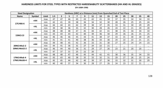
128
HARDNESS LIMITS FOR STEEL TYPES WITH RESTRICTED HARDENABILITY SCATTERBANDS (HH AND HL GRADES) (EN 10084-1998)
Steel Designation Hardness (HRC) at a Distance (mm) from Quenched End of Test Piece Name Symbol Limit 1.5 3 5 7 9 11 13 15 20 25 30 35 40
17CrNi6-6 +HH
max 47 47 46 45 43 42 41 39 37 35 34 34 33
min 42 41 39 38 36 34 32 30 28 26 25 25 24
+HL max 44 44 43 42 39 38 37 35 33 31 30 29 29
min 39 38 36 35 32 30 28 26 24 22 21 20 20
15NiCr13 +HH
max 48 48 48 47 45 44 42 41 38 35 34 34 33
min 43 43 43 42 40 39 36 34 29 26 26 25 25
+HL max 46 46 46 45 43 41 38 37 33 31 30 30 29
min 41 41 41 40 38 36 33 30 24 22 22 21 21
20NiCrMo2-2 20NiCrMoS2-2
+HH max 49 48 45 42 36 33 31 30 27 25 24 24 23
min 44 41 36 31 27 24 22 21 … … … … …
+HL max 46 44 40 36 31 29 27 26 23 21 20 20 …
min 47 37 31 25 22 20 … … … … … … …
17NiCrMo6-4 17NiCrMoS6-4
+HH max 48 48 47 46 45 44 42 41 38 36 35 34 33
min 43 43 40 38 35 33 32 31 29 27 26 25 24
+HL max 45 45 44 42 40 39 37 36 33 32 31 30 29
min 40 40 37 34 30 28 27 26 24 23 22 21 …
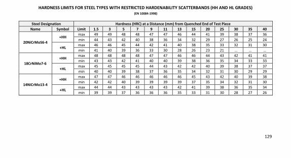
129
HARDNESS LIMITS FOR STEEL TYPES WITH RESTRICTED HARDENABILITY SCATTERBANDS (HH AND HL GRADES) (EN 10084-1998)
Steel Designation Hardness (HRC) at a Distance (mm) from Quenched End of Test Piece Name Symbol Limit 1.5 3 5 7 9 11 13 15 20 25 30 35 40
20NiCrMoS6-4 +HH
max 49 49 48 48 47 47 46 44 41 39 38 37 36
min 44 43 42 40 38 36 34 32 29 27 26 25 24
+HL max 46 46 45 44 42 41 40 38 35 33 32 31 30
min 41 40 39 36 33 30 28 26 23 21 … … …
18CrNiMo7-6 +HH
max 48 48 48 48 47 47 46 46 44 43 42 41 41
min 43 43 42 41 40 40 39 38 36 35 34 33 33
+HL max 45 45 45 45 44 43 42 42 40 39 38 37 37
min 40 40 39 38 37 36 35 34 32 31 30 29 29
14NiCrMo13-4 +HH
max 47 47 46 46 46 46 46 45 43 42 40 39 38
min 42 42 40 39 39 39 39 37 35 34 32 31 30
+HL max 44 44 43 43 43 43 42 41 39 38 36 35 34
min 39 39 37 36 36 36 35 33 31 30 28 27 26

130
NOTES
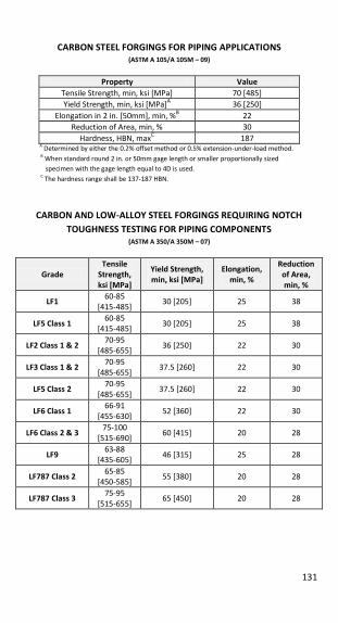
131
CARBON STEEL FORGINGS FOR PIPING APPLICATIONS (ASTM A 105/A 105M – 09)
Property Value Tensile Strength, min, ksi [MPa] 70 [485]
Yield Strength, min, ksi [MPa]A 36 [250]
Elongation in 2 in. [50mm], min, %B 22
Reduction of Area, min, % 30
Hardness, HBN, maxC 187
A Determined by either the 0.2% offset method or 0.5% extension-under-load method.
B When standard round 2 in. or 50mm gage length or smaller proportionally sized
specimen with the gage length equal to 4D is used.
C The hardness range shall be 137-187 HBN.
CARBON AND LOW-ALLOY STEEL FORGINGS REQUIRING NOTCH TOUGHNESS TESTING FOR PIPING COMPONENTS
(ASTM A 350/A 350M – 07)
Grade Tensile
Strength, ksi [MPa]
Yield Strength, min, ksi [MPa]
Elongation, min, %
Reduction of Area, min, %
LF1 60-85
[415-485] 30 [205] 25 38
LF5 Class 1 60-85
[415-485] 30 [205] 25 38
LF2 Class 1 & 2 70-95
[485-655] 36 [250] 22 30
LF3 Class 1 & 2 70-95
[485-655] 37.5 [260] 22 30
LF5 Class 2 70-95
[485-655] 37.5 [260] 22 30
LF6 Class 1 66-91
[455-630] 52 [360] 22 30
LF6 Class 2 & 3 75-100
[515-690] 60 [415] 20 28
LF9 63-88
[435-605] 46 [315] 25 28
LF787 Class 2 65-85
[450-585] 55 [380] 20 28
LF787 Class 3 75-95
[515-655] 65 [450] 20 28
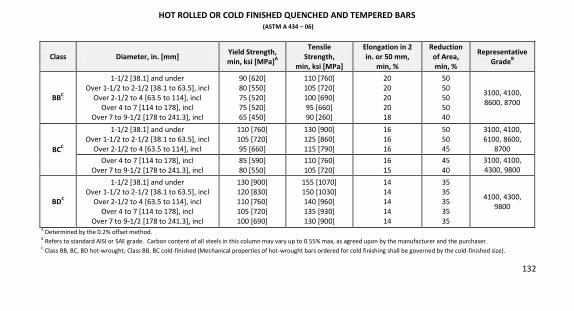
132
HOT ROLLED OR COLD FINISHED QUENCHED AND TEMPERED BARS (ASTM A 434 – 06)
Class Diameter, in. [mm] Yield Strength, min, ksi [MPa]A
Tensile Strength,
min, ksi [MPa]
Elongation in 2 in. or 50 mm,
min, %
Reduction of Area, min, %
Representative GradeB
BBC
1-1/2 [38.1] and under
Over 1-1/2 to 2-1/2 [38.1 to 63.5], incl
Over 2-1/2 to 4 [63.5 to 114], incl
Over 4 to 7 [114 to 178], incl
Over 7 to 9-1/2 [178 to 241.3], incl
90 [620]
80 [550]
75 [520]
75 [520]
65 [450]
110 [760]
105 [720]
100 [690]
95 [660]
90 [260]
20
20
20
20
18
50
50
50
50
40
3100, 4100,
8600, 8700
BCC
1-1/2 [38.1] and under
Over 1-1/2 to 2-1/2 [38.1 to 63.5], incl
Over 2-1/2 to 4 [63.5 to 114], incl
110 [760]
105 [720]
95 [660]
130 [900]
125 [860]
115 [790]
16
16
16
50
50
45
3100, 4100,
6100, 8600,
8700
Over 4 to 7 [114 to 178], incl
Over 7 to 9-1/2 [178 to 241.3], incl
85 [590]
80 [550]
110 [760]
105 [720]
16
15
45
40
3100, 4100,
4300, 9800
BDC
1-1/2 [38.1] and under
Over 1-1/2 to 2-1/2 [38.1 to 63.5], incl
Over 2-1/2 to 4 [63.5 to 114], incl
Over 4 to 7 [114 to 178], incl
Over 7 to 9-1/2 [178 to 241.3], incl
130 [900]
120 [830]
110 [760]
105 [720]
100 [690]
155 [1070]
150 [1030]
140 [960]
135 [930]
130 [900]
14
14
14
14
14
35
35
35
35
35
4100, 4300,
9800
A Determined by the 0.2% offset method.
B Refers to standard AISI or SAE grade. Carbon content of all steels in this column may vary up to 0.55% max, as agreed upon by the manufacturer and the purchaser.
C Class BB, BC, BD hot-wrought; Class BB, BC cold-finished (Mechanical properties of hot-wrought bars ordered for cold finishing shall be governed by the cold-finished size).
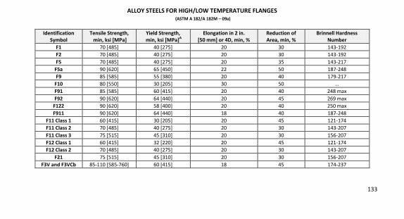
133
ALLOY STEELS FOR HIGH/LOW TEMPERATURE FLANGES (ASTM A 182/A 182M – 09a)
Identification Symbol
Tensile Strength, min, ksi [MPa]
Yield Strength, min, ksi [MPa]A
Elongation in 2 in. [50 mm] or 4D, min, %
Reduction of Area, min, %
Brinnell Hardness Number
F1 70 [485] 40 [275] 20 30 143-192
F2 70 [485] 40 [275] 20 30 143-192
F5 70 [485] 40 [275] 20 35 143-217
F5a 90 [620] 65 [450] 22 50 187-248
F9 85 [585] 55 [380] 20 40 179-217
F10 80 [550] 30 [205] 30 50 …
F91 85 [585] 60 [415] 20 40 248 max
F92 90 [620] 64 [440] 20 45 269 max
F122 90 [620] 58 [400] 20 40 250 max
F911 90 [620] 64 [440] 18 40 187-248
F11 Class 1 60 [415] 30 [205] 20 45 121-174
F11 Class 2 70 [485] 40 [275] 20 30 143-207
F11 Class 3 75 [515] 45 [310] 20 30 156-207
F12 Class 1 60 [415] 32 [220] 20 45 121-174
F12 Class 2 70 [485] 40 [275] 20 30 143-207
F21 75 [515] 45 [310] 20 30 156-207
F3V and F3VCb 85-110 [585-760] 60 [415] 18 45 174-237
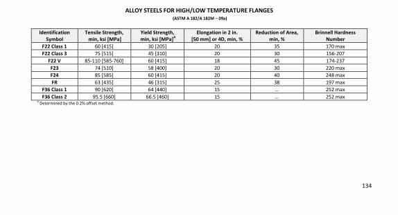
134
ALLOY STEELS FOR HIGH/LOW TEMPERATURE FLANGES (ASTM A 182/A 182M – 09a)
Identification Symbol
Tensile Strength, min, ksi [MPa]
Yield Strength, min, ksi [MPa]A
Elongation in 2 in. [50 mm] or 4D, min, %
Reduction of Area, min, %
Brinnell Hardness Number
F22 Class 1 60 [415] 30 [205] 20 35 170 max
F22 Class 3 75 [515] 45 [310] 20 30 156-207
F22 V 85-110 [585-760] 60 [415] 18 45 174-237
F23 74 [510] 58 [400] 20 30 220 max
F24 85 [585] 60 [415] 20 40 248 max
FR 63 [435] 46 [315] 25 38 197 max
F36 Class 1 90 [620] 64 [440] 15 … 252 max
F36 Class 2 95.5 [660] 66.5 [460] 15 … 252 max
A Determined by the 0.2% offset method.
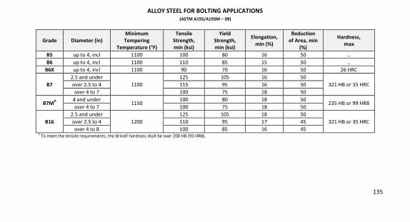
135
ALLOY STEEL FOR BOLTING APPLICATIONS (ASTM A193/A193M – 09)
Grade Diameter (in) Minimum Tempering
Temperature (°F)
Tensile Strength, min (ksi)
Yield Strength, min (ksi)
Elongation, min (%)
Reduction of Area, min
(%)
Hardness, max
B5 up to 4, incl 1100 100 80 16 50 …
B6 up to 4, incl 1100 110 85 15 50 …
B6X up to 4, incl 1100 90 70 16 50 26 HRC
B7 2.5 and under
1100
125 105 16 50
321 HB or 35 HRC
over 2.5 to 4 115 95 16 50
over 4 to 7 100 75 18 50
B7MA 4 and under
1150 100 80 18 50
235 HB or 99 HRB over 4 to 7 100 75 18 50
B16 2.5 and under
1200
125 105 18 50
321 HB or 35 HRC over 2.5 to 4 110 95 17 45
over 4 to 8 100 85 16 45
A To meet the tensile requirements, the Brinell hardness shall be over 200 HB (93 HRB).
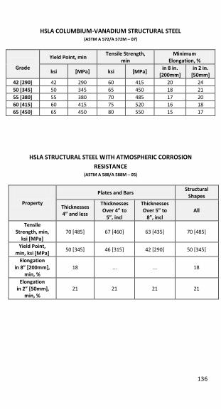
136
HSLA COLUMBIUM-VANADIUM STRUCTURAL STEEL (ASTM A 572/A 572M – 07)
Grade
Yield Point, min Tensile Strength,
min Minimum
Elongation, %
ksi [MPa] ksi [MPa] in 8 in.
[200mm] in 2 in.
[50mm] 42 [290] 42 290 60 415 20 24
50 [345] 50 345 65 450 18 21
55 [380] 55 380 70 485 17 20
60 [415] 60 415 75 520 16 18
65 [450] 65 450 80 550 15 17
HSLA STRUCTURAL STEEL WITH ATMOSPHERIC CORROSION RESISTANCE
(ASTM A 588/A 588M – 05)
Property
Plates and Bars Structural
Shapes
Thicknesses 4” and less
Thicknesses Over 4” to
5”, incl
Thicknesses Over 5” to
8”, incl
All
Tensile Strength, min,
ksi [MPa] 70 [485] 67 [460] 63 [435] 70 [485]
Yield Point, min, ksi [MPa]
50 [345] 46 [315] 42 [290] 50 [345]
Elongation in 8” [200mm],
min, %
18
...
...
18
Elongation in 2” [50mm],
min, %
21
21
21
21
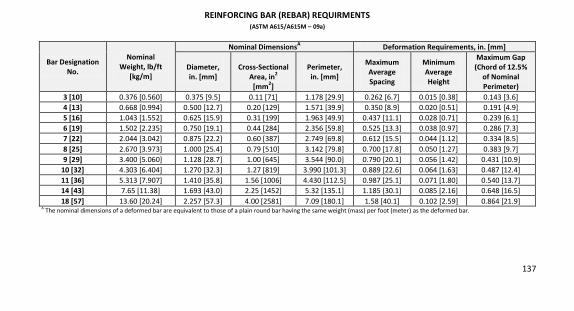
137
REINFORCING BAR (REBAR) REQUIRMENTS (ASTM A615/A615M – 09a)
Bar Designation No.
Nominal Weight, lb/ft
[kg/m]
Nominal DimensionsA Deformation Requirements, in. [mm]
Diameter, in. [mm]
Cross-Sectional
Area, in2 [mm2]
Perimeter, in. [mm]
Maximum Average Spacing
Minimum Average Height
Maximum Gap (Chord of 12.5%
of Nominal Perimeter)
3 [10] 0.376 [0.560] 0.375 [9.5] 0.11 [71] 1.178 [29.9] 0.262 [6.7] 0.015 [0.38] 0.143 [3.6]
4 [13] 0.668 [0.994] 0.500 [12.7] 0.20 [129] 1.571 [39.9] 0.350 [8.9] 0.020 [0.51] 0.191 [4.9]
5 [16] 1.043 [1.552] 0.625 [15.9] 0.31 [199] 1.963 [49.9] 0.437 [11.1] 0.028 [0.71] 0.239 [6.1]
6 [19] 1.502 [2.235] 0.750 [19.1] 0.44 [284] 2.356 [59.8] 0.525 [13.3] 0.038 [0.97] 0.286 [7.3]
7 [22] 2.044 [3.042] 0.875 [22.2] 0.60 [387] 2.749 [69.8] 0.612 [15.5] 0.044 [1.12] 0.334 [8.5]
8 [25] 2.670 [3.973] 1.000 [25.4] 0.79 [510] 3.142 [79.8] 0.700 [17.8] 0.050 [1.27] 0.383 [9.7]
9 [29] 3.400 [5.060] 1.128 [28.7] 1.00 [645] 3.544 [90.0] 0.790 [20.1] 0.056 [1.42] 0.431 [10.9]
10 [32] 4.303 [6.404] 1.270 [32.3] 1.27 [819] 3.990 [101.3] 0.889 [22.6] 0.064 [1.63] 0.487 [12.4]
11 [36] 5.313 [7.907] 1.410 [35.8] 1.56 [1006] 4.430 [112.5] 0.987 [25.1] 0.071 [1.80] 0.540 [13.7]
14 [43] 7.65 [11.38] 1.693 [43.0] 2.25 [1452] 5.32 [135.1] 1.185 [30.1] 0.085 [2.16] 0.648 [16.5]
18 [57] 13.60 [20.24] 2.257 [57.3] 4.00 [2581] 7.09 [180.1] 1.58 [40.1] 0.102 [2.59] 0.864 [21.9]
A The nominal dimensions of a deformed bar are equivalent to those of a plain round bar having the same weight (mass) per foot (meter) as the deformed bar.

138
REINFORCING BAR (REBAR) REQUIRMENTS (ASTM A615/A615M – 09a)
MECHANICAL PROPERTY REQUIREMENTS
Tensile strength, min, ksi [MPa]
Grade 40A Grade 60 Grade 75 Grade 80 60 [420] 90 [620] 100 [690] 150 [725]
Yield strength, min, ksi [MPa]
40 [280] 60 [420] 75 [520] 80 [550]
Bar Designation Number
Elongation in 8 in [200 mm], min, %
3 [10] 11 9 7 7
4,5 [13,16] 12 9 7 7
6 [19] 12 9 7 7
7,8 [22,25] ... 8 7 7
9,10,11 [29,32,36] ... 7 6 6
14,18 [43,57] ... 7 6 6 A Grade 40 bars are furnished only in sizes 3 through 6 [10 through 19].
BEND TEST REQUIREMENTS
Bar Designation No. Pin Diameter for Bend TestsA
Grade 40 Grade 60 Grade 75 Grade 80 3,4,5 [10,13,16] 3 1/2 dB
3 1/2 d 5d 5d 6 [19] 5d 5d 5d 5d
7,8 [22,25] ... 5d 5d 5d 9,10,11 [29,32,36] ... 7d 7d 7d 14,18 [43,57] (90°) ... 9d 9d 9d
A Test bends are 180° unless noted otherwise.
B d = nominal diameter of specimen.
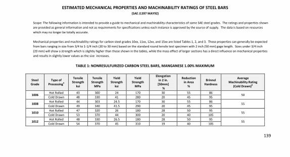
139
ESTIMATED MECHANICAL PROPERTIES AND MACHINABILITY RATINGS OF STEEL BARS (SAE J1397 MAY92)
Scope: The following information is intended to provide a guide to mechanical and machinability characteristics of some SAE steel grades. The ratings and properties shown
are provided as general information and not as requirements for specifications unless each instance is approved by the source of supply. The data is based on resources
which may no longer be totally accurate.
Mechanical properties and machinability ratings for carbon steel grades 10xx, 11xx, 12xx, and 15xx are listed Tables 1, 2, and 3. These properties can generally be expected
from bars ranging in size from 3/4 to 1-1/4 inch (20 to 30 mm) based on the standard round tensile test specimen with 2 inch (50 mm) gage length. Sizes under 3/4 inch
(20 mm) will show a strength which is slightly higher than those shown in the tables, while the mass effect of larger sections has a direct influence on mechanical properties
and results in slightly lower values as the size increases.
TABLE 1: NONRESULFURIZED CARBON STEEL BARS, MANGANESE 1.00% MAXIMUM
Steel Grade
Type of ProcessingA
Tensile Strength
ksi
Tensile Strength
MPa
Yield Strength
ksi
Yield Strength
MPa
Elongation in 2 in.
[50mm] %
Reduction in Area
%
Brinnel Hardness
Average Machinability Rating
(Cold Drawn)B
1006 Hot Rolled 43 300 24 170 30 55 86
50 Cold Drawn 48 330 41 280 20 45 95
1008 Hot Rolled 44 303 24.5 170 30 55 86
55 Cold Drawn 49 340 41.5 290 20 45 95
1010 Hot Rolled 47 320 26 180 28 50 95
55 Cold Drawn 53 370 44 300 20 40 105
1012 Hot Rolled 48 330 26.5 180 28 50 95
55 Cold Drawn 54 370 45 310 19 40 105
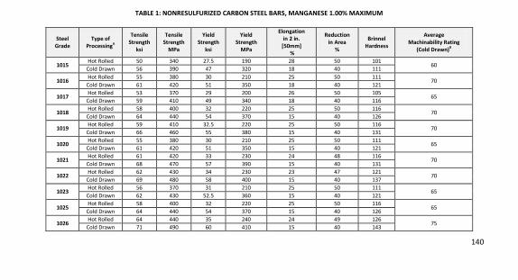
140
TABLE 1: NONRESULFURIZED CARBON STEEL BARS, MANGANESE 1.00% MAXIMUM
Steel Grade
Type of ProcessingA
Tensile Strength
ksi
Tensile Strength
MPa
Yield Strength
ksi
Yield Strength
MPa
Elongation in 2 in.
[50mm] %
Reduction in Area
%
Brinnel Hardness
Average Machinability Rating
(Cold Drawn)B
1015 Hot Rolled 50 340 27.5 190 28 50 101
60 Cold Drawn 56 390 47 320 18 40 111
1016 Hot Rolled 55 380 30 210 25 50 111
70 Cold Drawn 61 420 51 350 18 40 121
1017 Hot Rolled 53 370 29 200 26 50 105
65 Cold Drawn 59 410 49 340 18 40 116
1018 Hot Rolled 58 400 32 220 25 50 116
70 Cold Drawn 64 440 54 370 15 40 126
1019 Hot Rolled 59 410 32.5 220 25 50 116
70 Cold Drawn 66 460 55 380 15 40 131
1020 Hot Rolled 55 380 30 210 25 50 111
65 Cold Drawn 61 420 51 350 15 40 121
1021 Hot Rolled 61 420 33 230 24 48 116
70 Cold Drawn 68 470 57 390 15 40 131
1022 Hot Rolled 62 430 34 230 23 47 121
70 Cold Drawn 69 480 58 400 15 40 137
1023 Hot Rolled 56 370 31 210 25 50 111
65 Cold Drawn 62 430 52.5 360 15 40 121
1025 Hot Rolled 58 400 32 220 25 50 116
65 Cold Drawn 64 440 54 370 15 40 126
1026 Hot Rolled 64 440 35 240 24 49 126
75 Cold Drawn 71 490 60 410 15 40 143
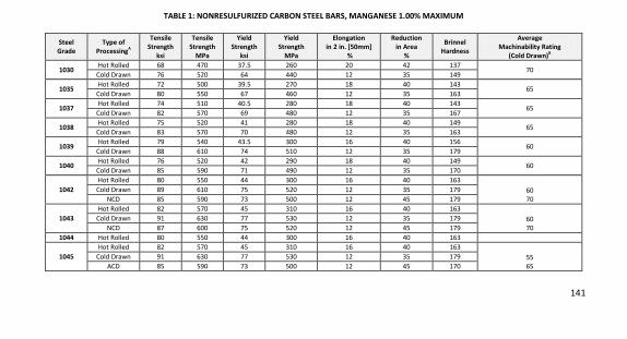
141
TABLE 1: NONRESULFURIZED CARBON STEEL BARS, MANGANESE 1.00% MAXIMUM
Steel Grade
Type of ProcessingA
Tensile Strength
ksi
Tensile Strength
MPa
Yield Strength
ksi
Yield Strength
MPa
Elongation in 2 in. [50mm]
%
Reduction in Area
%
Brinnel Hardness
Average Machinability Rating
(Cold Drawn)B
1030 Hot Rolled 68 470 37.5 260 20 42 137
70 Cold Drawn 76 520 64 440 12 35 149
1035 Hot Rolled 72 500 39.5 270 18 40 143
65 Cold Drawn 80 550 67 460 12 35 163
1037 Hot Rolled 74 510 40.5 280 18 40 143
65 Cold Drawn
82 570 69 480 12 35 167
1038 Hot Rolled 75 520 41 280 18 40 149
65 Cold Drawn 83 570 70 480 12 35 163
1039 Hot Rolled 79 540 43.5 300 16 40 156
60 Cold Drawn
88 610 74 510 12 35 179
1040 Hot Rolled 76 520 42 290 18 40 149
60 Cold Drawn 85 590 71 490 12 35 170
1042 Hot Rolled 80 550 44 300 16 40 163
60
70
Cold Drawn 89 610 75 520 12 35 179
NCD 85 590 73 500 12 45 179
1043 Hot Rolled 82 570 45 310 16 40 163
60
70
Cold Drawn 91 630 77 530 12 35 179
NCD 87 600 75 520 12 45 179
1044 Hot Rolled 80 550 44 300 16 40 163
1045 Hot Rolled 82 570 45 310 16 40 163
55
65
Cold Drawn 91 630 77 530 12 35 179
ACD 85 590 73 500 12 45 170
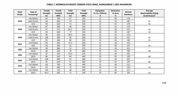
142
TABLE 1: NONRESULFURIZED CARBON STEEL BARS, MANGANESE 1.00% MAXIMUM
Steel Grade
Type of ProcessingA
Tensile Strength
ksi
Tensile Strength
MPa
Yield Strength
ksi
Yield Strength
MPa
Elongation in 2 in. [50mm]
%
Reduction in Area
%
Brinnel Hardness
Average Machinability Rating
(Cold Drawn)B
1046 Hot Rolled 85 590 47 320 15 40 170
55
65
Cold Drawn
94 650 79 540 12 35 187
ACD 90 620 75 520 12 45 179
1049 Hot Rolled 87 600 48 330 15 35 179
45
55
Cold Drawn
97 670 81.5 560 10 30 197
ACD 92 630 77 530 10 40 187
1050 Hot Rolled 90 620 49.5 340 15 35 179
45
55
Cold Drawn 100 690 84 580 10 30 197
ACD
95 660 80 550 10 40 189
1055 Hot Rolled 94 650 51.5 360 12 30 192
55 ACD
96 660 81 560 10 40 197
1060 Hot Rolled 98 680 54 370 12 30 201
60 SACD
90 420 70 480 10 45 183
1064 Hot Rolled 97 670 53.5 370 12 30 201
60 SACD
89 610 69 480 10 45 183
1065 Hot Rolled 100 690 55 380 12 30 207
60 SACD 92 630 71 490 10 45 187
1070 Hot Rolled 102 700 56 390 12 30 212
55 SACD 93 640 72 500 10 45 192
1074 Hot Rolled 105 720 58 400 12 30 217
55 SACD 94.5 650 73 500 10 40 192
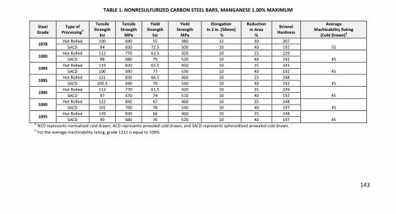
143
TABLE 1: NONRESULFURIZED CARBON STEEL BARS, MANGANESE 1.00% MAXIMUM
Steel Grade
Type of ProcessingA
Tensile Strength
ksi
Tensile Strength
MPa
Yield Strength
ksi
Yield Strength
MPa
Elongation in 2 in. [50mm]
%
Reduction in Area
%
Brinnel Hardness
Average Machinability Rating
(Cold Drawn)B
1078 Hot Rolled 100 690 55 380 12 30 207
55 SACD
94 650 72.5 500 10 40 192
1080 Hot Rolled 112 770 61.5 420 10 25 229
45 SACD
98 680 75 520 10 40 192
1084 Hot Rolled 119 820 65.5 450 10 25 241
45 SACD
100 690 77 530 10 40 192
1085 Hot Rolled 121 830 66.5 460 10 25 248
45 SACD
100.5 690 78 540 10 40 192
1086 Hot Rolled 112 770 61.5 420 10 25 229
45 SACD
97 670 74 510 10 40 192
1090 Hot Rolled 122 840 67 460 10 25 248
45 SACD
101 700 78 540 10 40 197
1095 Hot Rolled 120 830 66 460 10 25 248
45 SACD
99 680 76 520 10 40 197
A NCD represents normalized cold drawn, ACD represents annealed cold drawn, and SACD represents spheroidized annealed cold drawn.
B For the average machinability rating, grade 1212 is equal to 100%.
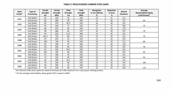
144
TABLE 2: RESULFURIZED CARBON STEEL BARS
Steel GradeA
Type of Processing
Tensile Strength
ksi
Tensile Strength
MPa
Yield Strength
ksi
Yield Strength
MPa
Elongation in 2 in [50mm]
%
Reduction in Area
%
Brinnel Hardness
Average Machinability Rating
(Cold Drawn)B
1117 Hot Rolled 62 430 34 230 23 47 121
90 Cold Drawn
69 480 58 400 15 40 137
1132 Hot Rolled 83 570 45.5 310 16 40 167
75 Cold Drawn
92 630 77 530 12 35 183
1137 Hot Rolled 88 610 48 330 15 35 179
70 Cold Drawn
98 680 82 570 10 30 197
1141 Hot Rolled 94 650 51.5 360 15 35 187
70 Cold Drawn
105.1 720 88 610 10 30 212
1144 Hot Rolled 97 670 53 370 15 35 197
80 Cold Drawn
108 740 90 620 10 30 217
1146 Hot Rolled 85 590 47 320 15 40 170
70 Cold Drawn
94 650 80 550 12 35 187
1151 Hot Rolled 92 630 50.5 340 15 35 187
65 Cold Drawn
102 700 86 590 10 30 207
1211 Hot Rolled 55 380 33 230 25 45 121
95 Cold Drawn
75 520 58 400 10 35 163
1212 Hot Rolled 56 390 33.5 230 25 45 121
100 Cold Drawn
78 540 60 410 10 35 167
1213 Hot Rolled 56 390 34 230 25 45 121
135 Cold Drawn
78 540 60 410 10 35 163 A
All 1100 and 1200 series steels are rated on the basis of 0.10% maximum Si or coarse grain melting practice.
B For the average machinability rating, grade 1212 is equal to 100%.
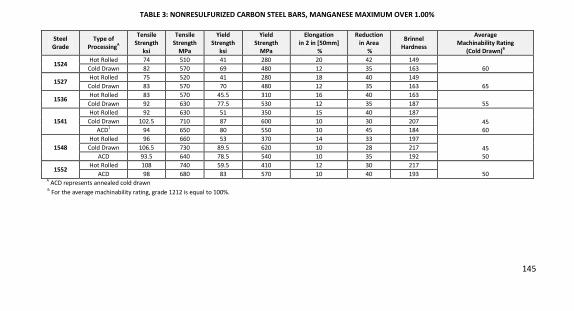
145
TABLE 3: NONRESULFURIZED CARBON STEEL BARS, MANGANESE MAXIMUM OVER 1.00%
Steel Grade
Type of ProcessingA
Tensile Strength
ksi
Tensile Strength
MPa
Yield Strength
ksi
Yield Strength
MPa
Elongation in 2 in [50mm]
%
Reduction in Area
%
Brinnel Hardness
Average Machinability Rating
(Cold Drawn)B
1524 Hot Rolled 74 510 41 280 20 42 149
60 Cold Drawn
82 570 69 480 12 35 163
1527 Hot Rolled 75 520 41 280 18 40 149
65 Cold Drawn
83 570 70 480 12 35 163
1536 Hot Rolled 83 570 45.5 310 16 40 163
55 Cold Drawn
92 630 77.5 530 12 35 187
1541 Hot Rolled 92 630 51 350 15 40 187
45
60
Cold Drawn
102.5 710 87 600 10 30 207
ACD1
94 650 80 550 10 45 184
1548 Hot Rolled 96 660 53 370 14 33 197
45
50
Cold Drawn
106.5 730 89.5 620 10 28 217
ACD
93.5 640 78.5 540 10 35 192
1552 Hot Rolled 108 740 59.5 410 12 30 217
50 ACD 98 680 83 570 10 40 193 A
ACD represents annealed cold drawn
B For the average machinability rating, grade 1212 is equal to 100%.
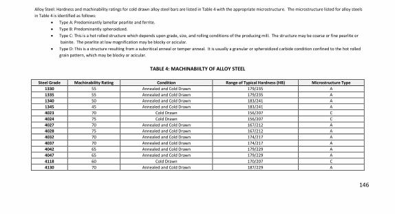
146
Alloy Steel: Hardness and machinability ratings for cold drawn alloy steel bars are listed in Table 4 with the appropriate microstructure. The microstructure listed for alloy steels
in Table 4 is identified as follows:
x Type A: Predominantly lamellar pearlite and ferrite.
x Type B: Predominantly spheroidized.
x Type C: This is a hot rolled structure which depends upon grade, size, and rolling conditions of the producing mill. The structure may be coarse or fine pearlite or
bainite. The pearlite at low magnification may be blocky or acicular.
x Type D: This is a structure resulting from a subcritical anneal or temper anneal. It is usually a granular or spheroidized carbide condition confined to the hot rolled
grain pattern, which may be blocky or acicular.
TABLE 4: MACHINABIILTY OF ALLOY STEEL
Steel Grade Machinability Rating Condition Range of Typical Hardness (HB) Microstructure Type 1330 55 Annealed and Cold Drawn 179/235 A
1335 55 Annealed and Cold Drawn 179/235 A
1340 50 Annealed and Cold Drawn 183/241 A
1345 45 Annealed and Cold Drawn 183/241 A
4023 70 Cold Drawn 156/207 C
4024 75 Cold Drawn 156/207 C
4027 70 Annealed and Cold Drawn 167/212 A
4028 75 Annealed and Cold Drawn 167/212 A
4032 70 Annealed and Cold Drawn 174/217 A
4037 70 Annealed and Cold Drawn 174/217 A
4042 65 Annealed and Cold Drawn 179/229 A
4047 65 Annealed and Cold Drawn 179/229 A
4118 60 Cold Drawn 170/207 C
4130 70 Annealed and Cold Drawn 187/229 A
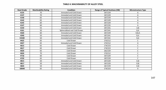
147
TABLE 4: MACHINABIILTY OF ALLOY STEEL
Steel Grade Machinability Rating Condition Range of Typical Hardness (HB) Microstructure Type 4135 70 Annealed and Cold Drawn 187/229 A
4137 70 Annealed and Cold Drawn 187/229 A
4140 65 Annealed and Cold Drawn 187/229 A
4142 65 Annealed and Cold Drawn 187/229 A
4145 60 Annealed and Cold Drawn 187/229 A
4147 60 Annealed and Cold Drawn 187/235 A
4150 55 Annealed and Cold Drawn 187/241 A,B
4161 50 Spheroidized and Cold Drawn 187/241 B,A
4320 60 Annealed and Cold Drawn 187/229 D,B,A
4340 50 Annealed and Cold Drawn 187/241 B,A
E4340 50 Annealed and Cold Drawn 187/241 B,A
4422 65 Cold Drawn 170/212 C
4427 65 Annealed and Cold Drawn 170/212 A
4615 65 Cold Drawn 174/223 C
4617 65 Cold Drawn 174/223 C
4620 65 Cold Drawn 182/229 C
4626 70 Cold Drawn 170/212 C
4718 60 Cold Drawn 187/229 C
4720 65 Cold Drawn 187/229 C
4815 50 Annealed and Cold Drawn 187/229 D,B
4817 50 Annealed and Cold Drawn 187/229 D,B
4820 50 Annealed and Cold Drawn 187/229 D,B
50B40 65 Annealed and Cold Drawn 174/223 A
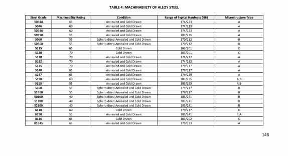
148
TABLE 4: MACHINABIILTY OF ALLOY STEEL
Steel Grade Machinability Rating Condition Range of Typical Hardness (HB) Microstructure Type 50B44 65 Annealed and Cold Drawn 174/223 A
5046 60 Annealed and Cold Drawn 174/223 A
50B46 60 Annealed and Cold Drawn 174/223 A
50B50 55 Annealed and Cold Drawn 183/235 A
5060 55 Spheroidized Annealed and Cold Drawn 170/212 B
50B60 55 Spheroidized Annealed and Cold Drawn 170/212 B
5115 65 Cold Drawn 163/201 C
5120 70 Cold Drawn 163/201 C
5130 70 Annealed and Cold Drawn 174/212 A
5132 70 Annealed and Cold Drawn 174/212 A
5135 70 Annealed and Cold Drawn 179/217 A
5140 65 Annealed and Cold Drawn 179/217 A
5147 65 Annealed and Cold Drawn 179/229 A
5150 60 Annealed and Cold Drawn 183/235 A,B
5155 55 Annealed and Cold Drawn 183/235 A,B
5160 55 Spheroidized Annealed and Cold Drawn 179/217 B
51B60 55 Spheroidized Annealed and Cold Drawn 179/217 B
50100 40 Spheroidized Annealed and Cold Drawn 183/241 B
51100 40 Spheroidized Annealed and Cold Drawn 183/241 B
52100 40 Spheroidized Annealed and Cold Drawn 183/241 B
6118 60 Cold Drawn 179/217 C
6150 55 Annealed and Cold Drawn 183/241 B,A
8115 65 Cold Drawn 163/202 C
81B45 65 Annealed and Cold Drawn 179/223 A
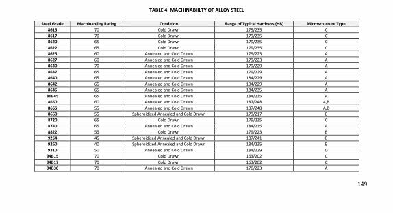
149
TABLE 4: MACHINABIILTY OF ALLOY STEEL
Steel Grade Machinability Rating Condition Range of Typical Hardness (HB) Microstructure Type 8615 70 Cold Drawn 179/235 C
8617 70 Cold Drawn 179/235 C
8620 65 Cold Drawn 179/235 C
8622 65 Cold Drawn 179/235 C
8625 60 Annealed and Cold Drawn 179/223 A
8627 60 Annealed and Cold Drawn 179/223 A
8630 70 Annealed and Cold Drawn 179/229 A
8637 65 Annealed and Cold Drawn 179/229 A
8640 65 Annealed and Cold Drawn 184/229 A
8642 65 Annealed and Cold Drawn 184/229 A
8645 65 Annealed and Cold Drawn 184/235 A
86B45 65 Annealed and Cold Drawn 184/235 A
8650 60 Annealed and Cold Drawn 187/248 A,B
8655 55 Annealed and Cold Drawn 187/248 A,B
8660 55 Spheroidized Annealed and Cold Drawn 179/217 B
8720 65 Cold Drawn 179/235 C
8740 65 Annealed and Cold Drawn 184/235 A
8822 55 Cold Drawn 179/223 B
9254 45 Spheroidized Annealed and Cold Drawn 187/241 B
9260 40 Spheroidized Annealed and Cold Drawn 184/235 B
9310 50 Annealed and Cold Drawn 184/229 D
94B15 70 Cold Drawn 163/202 C
94B17 70 Cold Drawn 163/202 C
94B30 70 Annealed and Cold Drawn 170/223 A
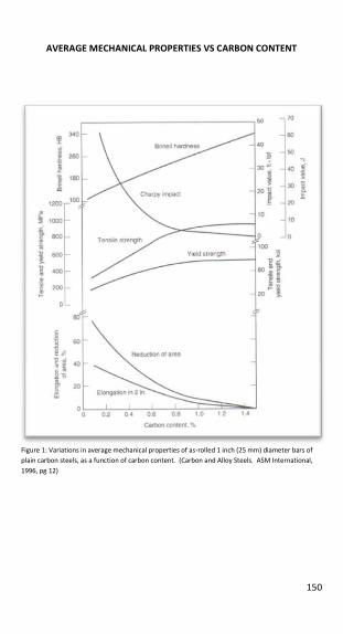
150
AVERAGE MECHANICAL PROPERTIES VS CARBON CONTENT
Figure 1: Variations in average mechanical properties of as-rolled 1 inch (25 mm) diameter bars of
plain carbon steels, as a function of carbon content. (Carbon and Alloy Steels. ASM International,
1996, pg 12)
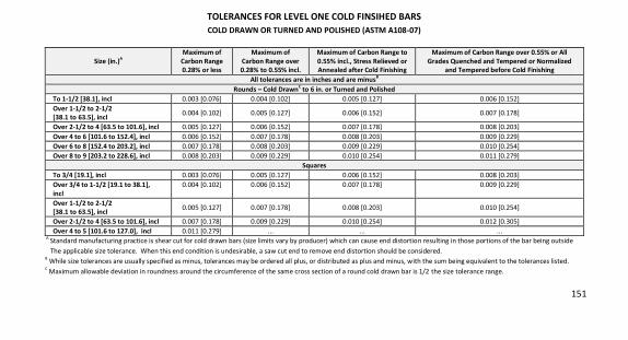
151
TOLERANCES FOR LEVEL ONE COLD FINSIHED BARS COLD DRAWN OR TURNED AND POLISHED (ASTM A108-07)
Size (in.)A Maximum of
Carbon Range 0.28% or less
Maximum of Carbon Range over 0.28% to 0.55% incl.
Maximum of Carbon Range to 0.55% incl., Stress Relieved or Annealed after Cold Finishing
Maximum of Carbon Range over 0.55% or All Grades Quenched and Tempered or Normalized
and Tempered before Cold Finishing All tolerances are in inches and are minusB
Rounds – Cold DrawnC to 6 in. or Turned and Polished To 1-1/2 [38.1], incl 0.003 [0.076] 0.004 [0.102] 0.005 [0.127] 0.006 [0.152]
Over 1-1/2 to 2-1/2 [38.1 to 63.5], incl
0.004 [0.102] 0.005 [0.127] 0.006 [0.152] 0.007 [0.178]
Over 2-1/2 to 4 [63.5 to 101.6], incl 0.005 [0.127] 0.006 [0.152] 0.007 [0.178] 0.008 [0.203]
Over 4 to 6 [101.6 to 152.4], incl 0.006 [0.152] 0.007 [0.178] 0.008 [0.203] 0.009 [0.229]
Over 6 to 8 [152.4 to 203.2], incl 0.007 [0.178] 0.008 [0.203] 0.009 [0.229] 0.010 [0.254]
Over 8 to 9 [203.2 to 228.6], incl 0.008 [0.203] 0.009 [0.229] 0.010 [0.254] 0.011 [0.279]
Squares To 3/4 [19.1], incl 0.003 [0.076] 0.005 [0.127] 0.006 [0.152] 0.008 [0.203]
Over 3/4 to 1-1/2 [19.1 to 38.1], incl
0.004 [0.102] 0.006 [0.152] 0.007 [0.178] 0.009 [0.229]
Over 1-1/2 to 2-1/2 [38.1 to 63.5], incl
0.005 [0.127] 0.007 [0.178] 0.008 [0.203] 0.010 [0.254]
Over 2-1/2 to 4 [63.5 to 101.6], incl 0.007 [0.178] 0.009 [0.229] 0.010 [0.254] 0.012 [0.305]
Over 4 to 5 [101.6 to 127.0], incl 0.011 [0.279] ... ... ... A
Standard manufacturing practice is shear cut for cold drawn bars (size limits vary by producer) which can cause end distortion resulting in those portions of the bar being outside
The applicable size tolerance. When this end condition is undesirable, a saw cut end to remove end distortion should be considered. B
While size tolerances are usually specified as minus, tolerances may be ordered all plus, or distributed as plus and minus, with the sum being equivalent to the tolerances listed. C
Maximum allowable deviation in roundness around the circumference of the same cross section of a round cold drawn bar is 1/2 the size tolerance range.
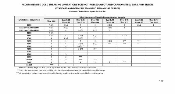
152
RECOMMENDED COLD SHEARING LIMITATIONS FOR HOT-ROLLED ALLOY AND CARBON STEEL BARS AND BILLETS (STANDARD AND FORMERLY STANDARD AISI AND SAE GRADES)
Maximum Dimension of Square Section (in)*
Grade Series Designation When Maximum of Specified Percent Carbon Range Is:
Thru 0.20 Over 0.20 Thru 0.25
Over 0.25 Thru 0.33
Over 0.33 Thru 0.44
Over 0.44 Thru 0.49
Over 0.49 Thru 0.55
Over 0.55 Thru 0.76
Over 0.76 Thru 1.05
10XX 4-1/2 4-1/2 4 3 2-1/2 2 1-1/2 1
11XX thru 1.00 max Mn 4-1/2 4-1/2 4 3 2-1/2 2
11XX over 1.00 max Mn 4-1/4 4 3-1/2 2-1/2 2
12XX 4-1/2
15XX 4-1/4 4 3-1/2 2-1/2 2 1-1/2 1
13XX 4 3-1/2 2-1/2 2**
40XX 4 4 4 3 2-1/2 2** ***
41XX 4 4 3-1/2 2-1/2 *** *** ***
43XX 4 4 1-1/2**
46XX 4 4 3-1/2 2**
47XX 4
48XX 4 3
50XX 4 2 ***
50BXX 2 2** *** ***
51XX 4 4 4 3 2 ***
51BXX ***
* Refer to Table on Page 158 and 159 for Equivalent Round sizes, based on cross sectional area.
** Sizes 1 inch square and smaller should be cold shearing quality or thermally treated before cold shearing.
*** All sizes in this carbon range should be cold shearing quality or thermally treated before cold shearing.
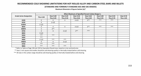
153
RECOMMENDED COLD SHEARING LIMITATIONS FOR HOT-ROLLED ALLOY AND CARBON STEEL BARS AND BILLETS (STANDARD AND FORMERLY STANDARD AISI AND SAE GRADES)
Maximum Dimension of Square Section (in)*
Grade Series Designation When Maximum of Specified Percent Carbon Range Is:
Thru 0.20 Over 0.20 Thru 0.25
Over 0.25 Thru 0.33
Over 0.33 Thru 0.44
Over 0.44 Thru 0.49
Over 0.49 Thru 0.55
Over 0.55 Thru 0.76
Over 0.76 Thru 1.05
61XX 4 4 3 2-1/2 2** *** ***
81XX 4 2-1/2
81BXX 2-1/2
86XX 4 4 3 2-1/2 2** *** ***
86BXX 3 2**
87XX 4 4 2-1/2 2** ***
88XX 3-1/2
92XX *** ***
93XX ***
94XX 2-1/2 *** ***
94BXX 4 4 2-1/2
97XX *** ***
98XX *** *** ***
* Refer to Table on Page 158 and 159 for Equivalent Round sizes, based on cross sectional area.
** Sizes 1 inch square and smaller should be cold shearing quality or thermally treated before cold shearing.
*** All sizes in this carbon range should be cold shearing quality or thermally treated before cold shearing.
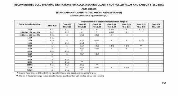
154
RECOMMENDED COLD SHEARING LIMITATIONS FOR COLD SHEARING QUALITY HOT ROLLED ALLOY AND CARBON STEEL BARS AND BILLETS
(STANDARD AND FORMERLY STANDARD AISI AND SAE GRADES) Maximum Dimension of Square Section (in.)*
Grade Series Designation When Maximum of Specified Percent Carbon Range Is:
Thru 0.20 Over 0.20 Thru 0.25
Over 0.25 Thru 0.33
Over 0.33 Thru 0.44
Over 0.44 Thru 0.49
Over 0.49 Thru 0.55
Over 0.55 Thru 0.76
Over 0.76 Thru 1.05
10XX 6-1/2 6-1/2 6 5 4-1/2 4 3-1/2
11XX thru 1.00 max Mn 6-1/2 6-1/2 6 5 4-1/2 4
11XX over 1.00 max Mn 6-1/4 6 5-1/2 4-1/2 4
12XX 6-1/2
15XX 6-1/4 6 5-1/2 4-1/2 4 3 2-1/4
13XX 5 4-3/4 4-1/2 4
40XX 5 5 4-3/4 4-1/2 4-1/2 4-1/2 **
41XX 5 5 4-3/4 4-1/4 4 3 **
43XX 4-3/4 4-3/4 **
46XX 5 5 4-3/4 4-1/4
47XX 5
48XX 5 4-3/4
50XX 5 4-1/4 **
50BXX 4-1/2 4-1/4 3-1/2 **
51XX 5 5 4-3/4 4-1/2 4 3-1/4
51BXX 4 3-1/4 **
* Refer to Table on page 158 and 159 for Equivalent Round size, based on cross sectional area.
** All sizes in this carbon range should be cold shearing quality or thermally treated before cold shearing.
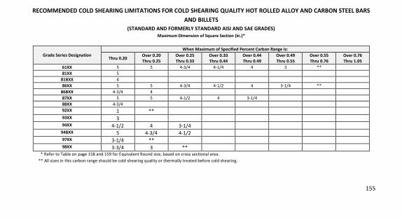
155
RECOMMENDED COLD SHEARING LIMITATIONS FOR COLD SHEARING QUALITY HOT ROLLED ALLOY AND CARBON STEEL BARS AND BILLETS
(STANDARD AND FORMERLY STANDARD AISI AND SAE GRADES) Maximum Dimension of Square Section (in.)*
Grade Series Designation When Maximum of Specified Percent Carbon Range Is:
Thru 0.20 Over 0.20 Thru 0.25
Over 0.25 Thru 0.33
Over 0.33 Thru 0.44
Over 0.44 Thru 0.49
Over 0.49 Thru 0.55
Over 0.55 Thru 0.76
Over 0.76 Thru 1.05
61XX 5 5 4-3/4 4-1/4 4 3 **
81XX 5
81BXX 4
86XX 5 5 4-3/4 4-1/2 4 3-1/4 **
86BXX 4-3/4 4
87XX 5 5 4-1/2 4 3-1/4
88XX 4-3/4
92XX 1 **
93XX 3
94XX 4-1/2 4 3-1/4
94BXX 5 4-3/4 4-1/2
97XX 3-1/4 **
98XX 3-3/4 3 **
* Refer to Table on page 158 and 159 for Equivalent Round size, based on cross sectional area.
** All sizes in this carbon range should be cold shearing quality or thermally treated before cold shearing.
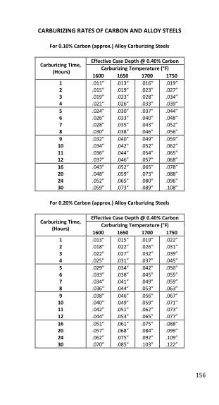
156
CARBURIZING RATES OF CARBON AND ALLOY STEELS
For 0.10% Carbon (approx.) Alloy Carburizing Steels
Carburizing Time, (Hours)
Effective Case Depth @ 0.40% Carbon Carburizing Temperature (°F)
1600 1650 1700 1750 1 .011” .013” .016” .019”
2 .015” .019” .023” .027”
3 .019” .023” .028” .034”
4 .021” .026” .033” .039”
5 .024” .030” .037” .044”
6 .026” .033” .040” .048”
7 .028” .035” .043” .052”
8 .030” .038” .046” .056”
9 .032” .040” .049” .059”
10 .034” .042” .052” .062”
11 .036” .044” .054” .065”
12 .037” .046” .057” .068”
16 .043” .052” .065” .078”
20 .048” .059” .073” .088”
24 .052” .065” .080” .096”
30 .059” .073” .089” .108”
For 0.20% Carbon (approx.) Alloy Carburizing Steels
Carburizing Time, (Hours)
Effective Case Depth @ 0.40% Carbon Carburizing Temperature (°F)
1600 1650 1700 1750 1 .013” .015” .019” .022”
2 .018” .022” .026” .031”
3 .022” .027” .032” .039”
4 .025” .031” .037” .045”
5 .029” .034” .042” .050”
6 .033” .038” .045” .055”
7 .034” .041” .049” .059”
8 .036” .044” .053” .063”
9 .038” .046” .056” .067”
10 .040” .049” .059” .071”
11 .042” .051” .062” .073”
12 .044” .053” .065” .077”
16 .051” .061” .075” .088”
20 .057” .068” .084” .099”
24 .062” .075” .092” .109”
30 .070” .085” .103” .122”
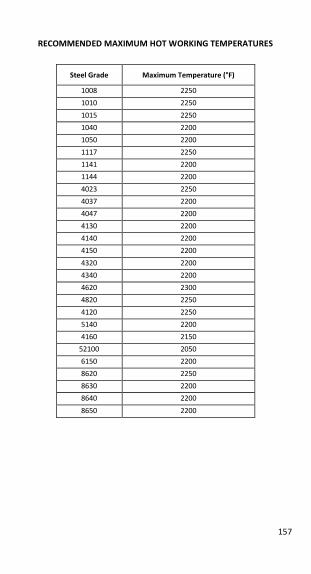
157
RECOMMENDED MAXIMUM HOT WORKING TEMPERATURES
Steel Grade Maximum Temperature (°F)
1008 2250
1010 2250
1015 2250
1040 2200
1050 2200
1117 2250
1141 2200
1144 2200
4023 2250
4037 2200
4047 2200
4130 2200
4140 2200
4150 2200
4320 2200
4340 2200
4620 2300
4820 2250
4120 2250
5140 2200
4160 2150
52100 2050
6150 2200
8620 2250
8630 2200
8640 2200
8650 2200
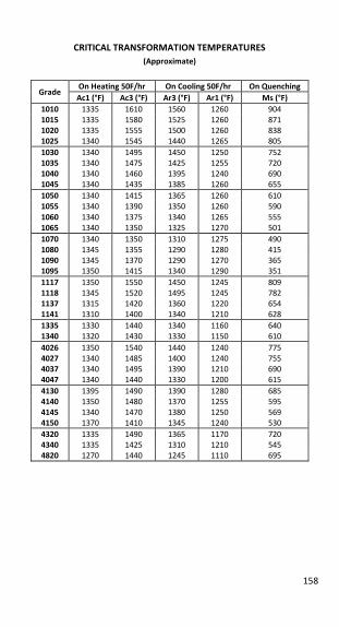
158
CRITICAL TRANSFORMATION TEMPERATURES (Approximate)
Grade On Heating 50F/hr On Cooling 50F/hr On Quenching Ac1 (°F) Ac3 (°F) Ar3 (°F) Ar1 (°F) Ms (°F)
1010 1335 1610 1560 1260 904
1015 1335 1580 1525 1260 871
1020 1335 1555 1500 1260 838
1025 1340 1545 1440 1265 805
1030 1340 1495 1450 1250 752
1035 1340 1475 1425 1255 720
1040 1340 1460 1395 1240 690
1045 1340 1435 1385 1260 655
1050 1340 1415 1365 1260 610
1055 1340 1390 1350 1260 590
1060 1340 1375 1340 1265 555
1065 1340 1350 1325 1270 501
1070 1340 1350 1310 1275 490
1080 1345 1355 1290 1280 415
1090 1345 1370 1290 1270 365
1095 1350 1415 1340 1290 351
1117 1350 1550 1450 1245 809
1118 1345 1520 1495 1245 782
1137 1315 1420 1360 1220 654
1141 1310 1400 1340 1210 628
1335 1330 1440 1340 1160 640
1340 1320 1430 1330 1150 610
4026 1350 1540 1440 1240 775
4027 1340 1485 1400 1240 755
4037 1340 1495 1390 1210 690
4047 1340 1440 1330 1200 615
4130 1395 1490 1390 1280 685
4140 1350 1480 1370 1255 595
4145 1340 1470 1380 1250 569
4150 1370 1410 1345 1240 530
4320 1335 1490 1365 1170 720
4340 1335 1425 1310 1210 545
4820 1270 1440 1245 1110 695
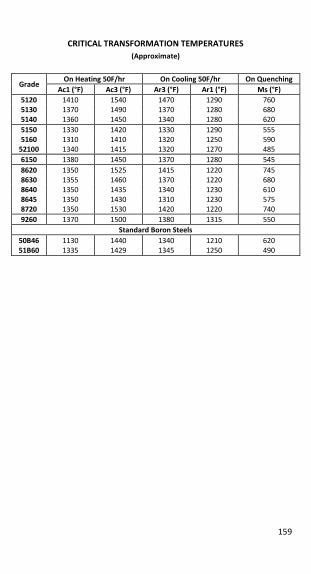
159
CRITICAL TRANSFORMATION TEMPERATURES (Approximate)
Grade On Heating 50F/hr On Cooling 50F/hr On Quenching
Ac1 (°F) Ac3 (°F) Ar3 (°F) Ar1 (°F) Ms (°F) 5120 1410 1540 1470 1290 760
5130 1370 1490 1370 1280 680
5140 1360 1450 1340 1280 620
5150 1330 1420 1330 1290 555
5160 1310 1410 1320 1250 590
52100 1340 1415 1320 1270 485
6150 1380 1450 1370 1280 545
8620 1350 1525 1415 1220 745
8630 1355 1460 1370 1220 680
8640 1350 1435 1340 1230 610
8645 1350 1430 1310 1230 575
8720 1350 1530 1420 1220 740
9260 1370 1500 1380 1315 550
Standard Boron Steels 50B46 51B60
1130
1335
1440
1429
1340
1345
1210
1250
620
490
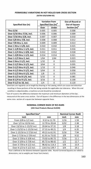
160
PERMISSIBLE VARIATIONS IN HOT-ROLLED BAR CROSS SECTION (ASTM A29/A29M-05)
Specified Size (in) Variation from
Specified Size (in)A Out-of-Round or
Out-of-Square Section (in)B Over Under
Thru 5/16 0.005 0.005 0.008
Over 5/16 thru 7/16, incl. 0.006 0.006 0.009
Over 7/16 thru 5/8, incl. 0.007 0.007 0.010
Over 5/8 thru 7/8, incl. 0.008 0.008 0.012
Over 7/8 thru 1, incl. 0.009 0.009 0.013
Over 1 thru 1-1/8, incl. 0.010 0.010 0.015
Over 1-1/8 thru 1-1/4, incl. 0.011 0.011 0.016
Over 1-1/4 thru 1-3/8, incl. 0.012 0.012 0.018
Over 1-3/8 thru 1-1/2, incl. 0.014 0.014 0.021
Over 1-1/2 thru 2, incl. 1/64 1/64 0.023
Over 2 thru 2-1/2, incl. 1/32 0 0.023
Over 2-1/2 thru 3-1/2, incl. 3/64 0 0.035
Over 3-1/2 thru 4-1/2, incl. 1/16 0 0.046
Over 4-1/2 thru 5-1/2, incl. 5/64 0 0.058
Over 5-1/2 thru 6-1/2, incl. 1/8 0 0.070
Over 6-1/2 to 8-1/4, incl. 5/32 0 0.085
Over 8-1/4 to 9-1/2, incl. 3/16 0 0.100
Over 9-1/2 to 10, incl. 1/4 0 0.120 A
Steel bars are regularly cut to length by shearing or hot sawing, which can cause end distortion
resulting in those portions of the bar being outside the applicable size tolerance. When this end
condition is objectionable, a machine cut end should be considered. B
Out-of-round is the difference between the maximum and minimum diameters of the bar,
measured at the same cross section. Out-of-Square is the difference in the two dimensions at the
same cross section of a square bar between opposite faces.
NOMINAL CORNER RADII OF RCS BARS (AISI Steel Products Manual AUG94)
Specified Size* Nominal Corner Radii inch mm inch mm
From 3/8 to 1/2 incl. 9.52 to 12.70 1/16 1.59
Over 1/2 to 13/16 incl. 12.70 to 20.64 3/32 2.38
Over 13/16 to 1-15/32 incl. 20.64 to 37.31 1/8 3.18
Over 1-15/32 to 1-15/16 incl. 37.31 to 49.21 1/4 6.35
Over 1-15/16 to 2-7/16 incl. 49.21 to 61.91 5/16 7.94
Over 2-7/16 to 2-7/8 incl. 61.91 to 73.02 3/8 9.52
Over 2-7/8 to 3-3/8 incl. 73.02 to 85.72 7/16 11.1
Over 3-3/8 to 3-7/8 incl. 85.72 to 98.42 1/2 12.7
Over 3-7/8 to 4-1/2 incl. 98.42 to 114.3 5/8 15.9
Over 4-1/2 to 5-1/2 incl. 114.3 to 139.7 3/4 19.1 *Size is defined as the distance between opposite sides. Round-Cornered Squares are rolled to
dimensions, not to weights per linear foot (meter).
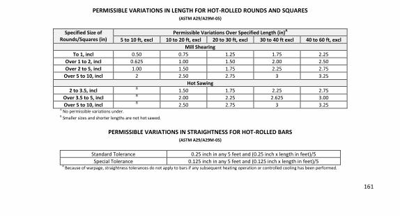
161
PERMISSIBLE VARIATIONS IN LENGTH FOR HOT-ROLLED ROUNDS AND SQUARES (ASTM A29/A29M-05)
Specified Size of Rounds/Squares (in)
Permissible Variations Over Specified Length (in)A
5 to 10 ft, excl 10 to 20 ft, excl 20 to 30 ft, excl 30 to 40 ft excl 40 to 60 ft, excl Mill Shearing
To 1, incl 0.50 0.75 1.25 1.75 2.25
Over 1 to 2, incl 0.625 1.00 1.50 2.00 2.50
Over 2 to 5, incl 1.00 1.50 1.75 2.25 2.75
Over 5 to 10, incl 2 2.50 2.75 3 3.25
Hot Sawing 2 to 3.5, incl B
1.50 1.75 2.25 2.75
Over 3.5 to 5, incl B 2.00 2.25 2.625 3.00
Over 5 to 10, incl B 2.50 2.75 3 3.25
A No permissible variations under.
B Smaller sizes and shorter lengths are not hot sawed.
PERMISSIBLE VARIATIONS IN STRAIGHTNESS FOR HOT-ROLLED BARS (ASTM A29/A29M-05)
Standard Tolerance 0.25 inch in any 5 feet and (0.25 inch x length in feet)/5
Special Tolerance 0.125 inch in any 5 feet and (0.125 inch x length in feet)/5
A Because of warpage, straightness tolerances do not apply to bars if any subsequent heating operation or controlled cooling has been performed.
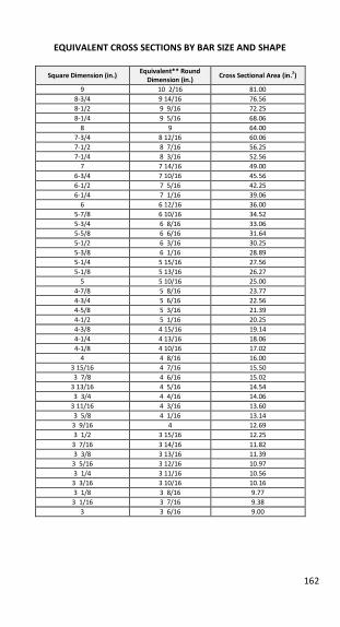
162
EQUIVALENT CROSS SECTIONS BY BAR SIZE AND SHAPE
Square Dimension (in.) Equivalent** Round
Dimension (in.) Cross Sectional Area (in.2)
9 10 2/16 81.00
8-3/4 9 14/16 76.56
8-1/2 9 9/16 72.25
8-1/4 9 5/16 68.06
8 9 64.00
7-3/4 8 12/16 60.06
7-1/2 8 7/16 56.25
7-1/4 8 3/16 52.56
7 7 14/16 49.00
6-3/4 7 10/16 45.56
6-1/2 7 5/16 42.25
6-1/4 7 1/16 39.06
6 6 12/16 36.00
5-7/8 6 10/16 34.52
5-3/4 6 8/16 33.06
5-5/8 6 6/16 31.64
5-1/2 6 3/16 30.25
5-3/8 6 1/16 28.89
5-1/4 5 15/16 27.56
5-1/8 5 13/16 26.27
5 5 10/16 25.00
4-7/8 5 8/16 23.77
4-3/4 5 6/16 22.56
4-5/8 5 3/16 21.39
4-1/2 5 1/16 20.25
4-3/8 4 15/16 19.14
4-1/4 4 13/16 18.06
4-1/8 4 10/16 17.02
4 4 8/16 16.00
3 15/16 4 7/16 15.50
3 7/8 4 6/16 15.02
3 13/16 4 5/16 14.54
3 3/4 4 4/16 14.06
3 11/16 4 3/16 13.60
3 5/8 4 1/16 13.14
3 9/16 4 12.69
3 1/2 3 15/16 12.25
3 7/16 3 14/16 11.82
3 3/8 3 13/16 11.39
3 5/16 3 12/16 10.97
3 1/4 3 11/16 10.56
3 3/16 3 10/16 10.16
3 1/8 3 8/16 9.77
3 1/16 3 7/16 9.38
3 3 6/16 9.00
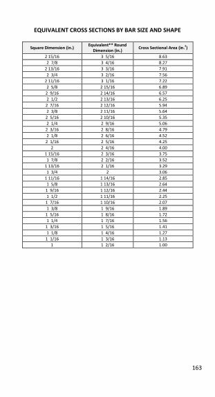
163
EQUIVALENT CROSS SECTIONS BY BAR SIZE AND SHAPE
Square Dimension (in.) Equivalent** Round
Dimension (in.) Cross Sectional Area (in.2)
2 15/16 3 5/16 8.63
2 7/8 3 4/16 8.27
2 13/16 3 3/16 7.91
2 3/4 3 2/16 7.56
2 11/16 3 1/16 7.22
2 5/8 2 15/16 6.89
2 9/16 2 14/16 6.57
2 1/2 2 13/16 6.25
2 7/16 2 12/16 5.94
2 3/8 2 11/16 5.64
2 5/16 2 10/16 5.35
2 1/4 2 9/16 5.06
2 3/16 2 8/16 4.79
2 1/8 2 6/16 4.52
2 1/16 2 5/16 4.25
2 2 4/16 4.00
1 15/16 2 3/16 3.75
1 7/8 2 2/16 3.52
1 13/16 2 1/16 3.29
1 3/4 2 3.06
1 11/16 1 14/16 2.85
1 5/8 1 13/16 2.64
1 9/16 1 12/16 2.44
1 1/2 1 11/16 2.25
1 7/16 1 10/16 2.07
1 3/8 1 9/16 1.89
1 5/16 1 8/16 1.72
1 1/4 1 7/16 1.56
1 3/16 1 5/16 1.41
1 1/8 1 4/16 1.27
1 1/16 1 3/16 1.13
1 1 2/16 1.00
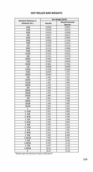
164
HOT ROLLED BAR WEIGHTS
Nominal Thickness or Diameter (in.)
Bar Weight (lb/ft)
Rounds Round Cornered
Squares 1/32 0.0026 0.0033
1/16 0.0104 0.0133
3/32 0.0234 0.0298
1/8 0.0417 0.0531
5/32 0.0651 0.0829
3/16 0.0938 0.1194
7/32 0.1276 0.1625
1/4 0.1667 0.2123
9/32 0.2110 0.2686
5/16 0.2605 0.3316
11/32 0.3152 0.4013
3/8 0.3751 0.4776
13/32 0.4402 0.5605
7/16 0.5105 0.6500
15/32 0.5861 0.7462
1/2 0.6668 0.8490
17/32 0.7528 0.9584
9/16 0.8439 1.075
19/32 0.9403 1.197
5/8 1.042 1.327
21/32 1.149 1.463
11/16 1.261 1.605
23/32 1.378 1.754
3/4 1.500 1.910
25/32 1.628 2.073
13/16 1.761 2.242
27/32 1.899 2.418
7/8 2.042 2.600
29/32 2.191 2.789
15/16 2.344 2.985
31/32 2.503 3.187
1 2.667 3.396
1 1/16 3.011 3.834
1 1/8 3.376 4.298
1 3/16 3.761 4.789
1 1/4 4.168 5.306
1 5/16 4.595 5.850
1 3/8 5.043 6.421
1 7/16 5.512 7.018
1 1/2 6.001 7.641
1 9/16 6.512 8.291
1 5/8 7.043 8.968
1 11/16 7.595 9.671
1 3/4 8.168 10.40
1 13/16 8.762 11.16
1 7/8 9.377 11.94
1 15/16 10.01 12.75
2 10.67 13.58
*Based upon the density of steel; 0.283 lbs/in3.
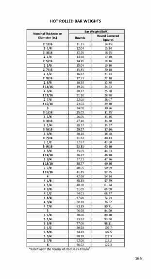
165
HOT ROLLED BAR WEIGHTS
Nominal Thickness or Diameter (in.)
Bar Weight (lb/ft)
Rounds Round Cornered
Squares 2 1/16 11.35 14.45
2 1/8 12.04 15.34
2 3/16 12.76 16.25
2 1/4 13.50 17.19
2 5/16 14.26 18.16
2 3/8 15.04 19.16
2 7/16 15.85 20.18
2 1/2 16.67 21.23
2 9/16 17.51 22.30
2 5/8 18.38 23.40
2 11/16 19.26 24.53
2 3/4 20.17 25.68
2 13/16 21.10 26.86
2 7/8 22.05 28.07
2 15/16 23.02 29.30
3 24.00 30.56
3 1/16 25.02 31.85
3 1/8 26.05 33.16
3 3/16 27.10 34.50
3 1/4 28.17 35.87
3 5/16 29.27 37.26
3 3/8 30.38 38.68
3 7/16 31.52 40.13
3 1/2 32.67 41.60
3 9/16 33.85 43.10
3 5/8 35.05 44.63
3 11/16 36.27 46.18
3 3/4 37.51 47.76
3 13/16 38.77 49.36
3 7/8 40.05 50.99
3 15/16 41.35 52.65
4 42.68 54.34
4 1/8 45.38 57.79
4 1/4 48.18 61.34
4 3/8 51.05 65.00
4 1/2 54.01 68.77
4 5/8 57.05 72.64
4 3/4 60.18 76.62
4 7/8 63.39 80.71
5 66.68 84.90
5 1/8 70.06 89.20
5 1/4 73.52 93.60
5 3/8 77.06 98.11
5 1/2 80.68 102.7
5 5/8 84.39 107.5
5 3/4 88.18 112.3
5 7/8 92.06 117.2
6 96.02 122.3
*Based upon the density of steel; 0.283 lbs/in3.
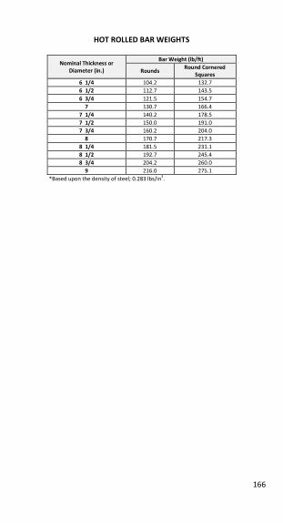
166
HOT ROLLED BAR WEIGHTS
Nominal Thickness or Diameter (in.)
Bar Weight (lb/ft)
Rounds Round Cornered
Squares 6 1/4 104.2 132.7
6 1/2 112.7 143.5
6 3/4 121.5 154.7
7 130.7 166.4
7 1/4 140.2 178.5
7 1/2 150.0 191.0
7 3/4 160.2 204.0
8 170.7 217.3
8 1/4 181.5 231.1
8 1/2 192.7 245.4
8 3/4 204.2 260.0
9 216.0 275.1
*Based upon the density of steel; 0.283 lbs/in3.
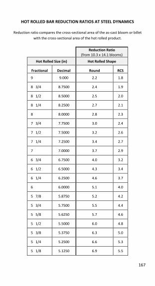
167
HOT ROLLED BAR REDUCTION RATIOS AT STEEL DYNAMICS
Reduction ratio compares the cross-sectional area of the as-cast bloom or billet
with the cross-sectional area of the hot rolled product.
Reduction Ratio
(from 10.3 x 14.1 blooms)
Hot Rolled Size (in) Hot Rolled Shape
Fractional Decimal Round RCS
9 9.000 2.2 1.8
8 3/4 8.7500 2.4 1.9
8 1/2 8.5000 2.5 2.0
8 1/4 8.2500 2.7 2.1
8 8.0000 2.8 2.3
7 3/4 7.7500 3.0 2.4
7 1/2 7.5000 3.2 2.6
7 1/4 7.2500 3.4 2.7
7 7.0000 3.7 2.9
6 3/4 6.7500 4.0 3.2
6 1/2 6.5000 4.3 3.4
6 1/4 6.2500 4.6 3.7
6 6.0000 5.1 4.0
5 7/8 5.8750 5.2 4.2
5 3/4 5.7500 5.5 4.4
5 5/8 5.6250 5.7 4.6
5 1/2 5.5000 6.0 4.8
5 3/8 5.3750 6.3 5.0
5 1/4 5.2500 6.6 5.3
5 1/8 5.1250 6.9 5.5
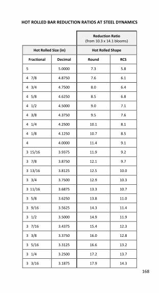
168
HOT ROLLED BAR REDUCTION RATIOS AT STEEL DYNAMICS
Reduction Ratio
(from 10.3 x 14.1 blooms)
Hot Rolled Size (in) Hot Rolled Shape
Fractional Decimal Round RCS
5 5.0000 7.3 5.8
4 7/8 4.8750 7.6 6.1
4 3/4 4.7500 8.0 6.4
4 5/8 4.6250 8.5 6.8
4 1/2 4.5000 9.0 7.1
4 3/8 4.3750 9.5 7.6
4 1/4 4.2500 10.1 8.1
4 1/8 4.1250 10.7 8.5
4 4.0000 11.4 9.1
3 15/16 3.9375 11.9 9.2
3 7/8 3.8750 12.1 9.7
3 13/16 3.8125 12.5 10.0
3 3/4 3.7500 12.9 10.3
3 11/16 3.6875 13.3 10.7
3 5/8 3.6250 13.8 11.0
3 9/16 3.5625 14.3 11.4
3 1/2 3.5000 14.9 11.9
3 7/16 3.4375 15.4 12.3
3 3/8 3.3750 16.0 12.8
3 5/16 3.3125 16.6 13.2
3 1/4 3.2500 17.2 13.7
3 3/16 3.1875 17.9 14.3
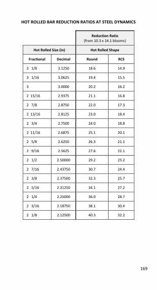
169
HOT ROLLED BAR REDUCTION RATIOS AT STEEL DYNAMICS
Reduction Ratio (from 10.3 x 14.1 blooms)
Hot Rolled Size (in) Hot Rolled Shape
Fractional Decimal Round RCS
3 1/8 3.1250 18.6 14.9
3 1/16 3.0625 19.4 15.5
3 3.0000 20.2 16.2
2 15/16 2.9375 21.1 16.8
2 7/8 2.8750 22.0 17.3
2 13/16 2.8125 23.0 18.4
2 3/4 2.7500 24.0 18.8
2 11/16 2.6875 25.1 20.1
2 5/8 2.6250 26.3 21.1
2 9/16 2.5625 27.6 22.1
2 1/2 2.50000 29.2 23.2
2 7/16 2.43750 30.7 24.4
2 3/8 2.37500 32.3 25.7
2 5/16 2.31250 34.1 27.2
2 1/4 2.25000 36.0 28.7
2 3/16 2.18750 38.1 30.4
2 1/8 2.12500 40.3 32.2
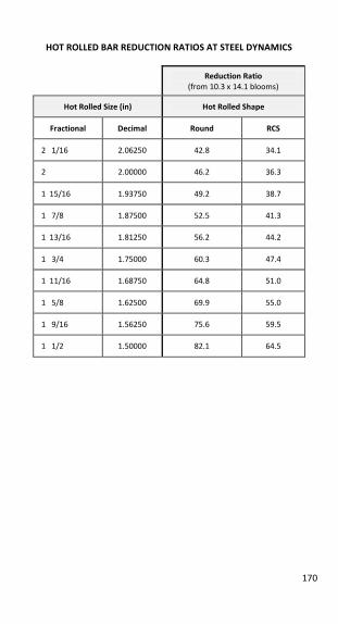
170
HOT ROLLED BAR REDUCTION RATIOS AT STEEL DYNAMICS
Reduction Ratio
(from 10.3 x 14.1 blooms)
Hot Rolled Size (in) Hot Rolled Shape
Fractional Decimal Round RCS
2 1/16 2.06250 42.8 34.1
2 2.00000 46.2 36.3
1 15/16 1.93750 49.2 38.7
1 7/8 1.87500 52.5 41.3
1 13/16 1.81250 56.2 44.2
1 3/4 1.75000 60.3 47.4
1 11/16 1.68750 64.8 51.0
1 5/8 1.62500 69.9 55.0
1 9/16 1.56250 75.6 59.5
1 1/2 1.50000 82.1 64.5
171
GRAIN SIZE
As Rolled Grain Size
As rolled grain size is sometimes referred to as ferritic grain size, ferrite pearlite
grain size, or room temperature gain size. As rolled grain size refers to the ASTM E
112 grain size number, which is given to the size of the ferrite and pearlite grains in
the microstructure of the steel as measured after cooling from hot rolling. As rolled
grain size is controlled by the associated rolling temperatures and cooling rates
following hot rolling.
Austenitic Grain Size (McQuaid-Ehn Grain Size) Austenitic grain size refers to the size of the grains which were present in the steel
when it was in the austenite phase. The austenite phase occurs at elevated
temperatures, generally greater than 1500°F. Austenite grain size requirements are
often specified for applications involving carburizing or heat treatment. For the
most part, fine grain steels are less sensitive to variations in heat treatments, while
coarse grained steels are deeper hardening and are more readily machinable.
Classification as a fine or coarse grain steel is determined by the steelmaking
procedure. If the procedure involves the addition of elements such as Al, V, Nb, Ti,
or a combination of these elements, the steel is fine grained. Steels without the
addition of these fine graining elements are referred to as coarse grained steels,
and the McQuaid-Ehn grain size limits are not applicable. For the most part, steels
with high C, high S, and/or high Mn tend to inherently resist grain coarsening.
When a steel is classified as fine grain steel, it refers to the fact that the steel has
the ability to retain a fine austenitic grain size when heated into the austenite
range. A steel which is classified as fine grain steel can still exhibit coarse grains at
elevated temperatures depending on the thermal cycle to which the steel was
exposed. Steels with an austenitic grain size number of 1 to 5 inclusive are referred
to as coarse grained, while steels with an austenitic grain size number greater than
5 are referred to as fine grained (as measured by ASTM E112). When Al is used as a
the grain refining element, the fine austenitic grain size requirement is met if, on
heat analysis, the total Al content is not less than 0.020%.
A steel producer will certify a heat of steel as fine or coarse grain based on the
steelmaking practice employed. If required, a grain size test can be performed to
certify the steel as fine or coarse grain. This certification only refers to the ability of
the steel to maintain a fine or coarse structure in the austenitic temperature range,
and does NOT guarantee that the steel will remain fine grain regardless of the
thermal conditions to which the steel is subjected to.
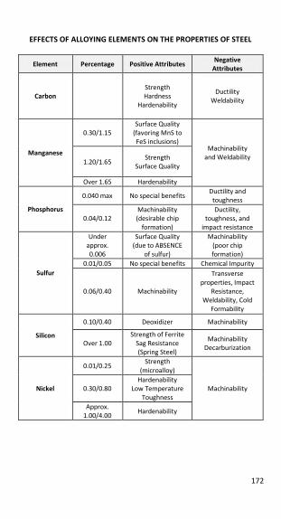
172
EFFECTS OF ALLOYING ELEMENTS ON THE PROPERTIES OF STEEL
Element Percentage Positive Attributes Negative
Attributes
Carbon
Strength
Hardness
Hardenability
Ductility
Weldability
Manganese
0.30/1.15
Surface Quality
(favoring MnS to
FeS inclusions) Machinability
and Weldability 1.20/1.65
Strength
Surface Quality
Over 1.65 Hardenability
Phosphorus
0.040 max No special benefits Ductility and
toughness
0.04/0.12
Machinability
(desirable chip
formation)
Ductility,
toughness, and
impact resistance
Sulfur
Under
approx.
0.006
Surface Quality
(due to ABSENCE
of sulfur)
Machinability
(poor chip
formation)
0.01/0.05 No special benefits Chemical Impurity
0.06/0.40 Machinability
Transverse
properties, Impact
Resistance,
Weldability, Cold
Formability
Silicon
0.10/0.40 Deoxidizer Machinability
Over 1.00
Strength of Ferrite
Sag Resistance
(Spring Steel)
Machinability
Decarburization
Nickel
0.01/0.25 Strength
(microalloy)
Machinability 0.30/0.80
Hardenability
Low Temperature
Toughness
Approx.
1.00/4.00 Hardenability
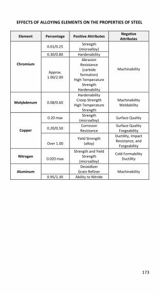
173
EFFECTS OF ALLOYING ELEMENTS ON THE PROPERTIES OF STEEL
Element Percentage Positive Attributes Negative
Attributes
Chromium
0.01/0.25 Strength
(microalloy)
Machinability
0.30/0.80 Hardenability
Approx.
1.00/2.00
Abrasion
Resistance
(carbide
formation)
High Temperature
Strength
Hardenability
Molybdenum 0.08/0.60
Hardenability
Creep Strength
High Temperature
Strength
Machinability
Weldability
Copper
0.20 max Strength
(microalloy) Surface Quality
0.20/0.50 Corrosion
Resistance
Surface Quality
Forgeability
Over 1.00
Yield Strength
(alloy)
Ductility, Impact
Resistance, and
Forgeability
Nitrogen
0.020 max
Strength and Yield
Strength
(microalloy)
Cold Formability
Ductility
Aluminum
Deoxidizer
Grain Refiner
Machinability
0.95/1.30 Ability to Nitride

174
NOTES
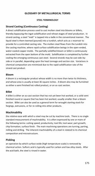
175
GLOSSARY OF METALLURGICAL TERMS
STEEL TERMINOLOGY
Strand Casting (Continuous Casting) A direct solidification process used to cast molten steel into blooms or billets,
thereby bypassing the ingot solidification and reheat stages of steel production. In
strand casting, a steel “melt” is tapped into a ladle in the conventional manner. The liquid steel is them teemed (poured) into a tundish, which acts as s reservoir to
provide for a controlled casting rate. The molten steel flows from the tundish into
the casting machine, where rapid surface solidification beings in the open-ended,
water-cooled copper molds. The partially solidified bloom or billet is continuously
extracted from the open bottom of the mold. Solidification is completed by further
cooling the emerging continuous cast steel. Several strands may be cast side-by-
side or in parallel, depending upon the heat tonnage and section size. Variations in
chemical composition are minimized due to the rapid solidification rate of the
strand cast product.
Bloom A bloom is a rectangular product whose width is no more than twice its thickness,
and whose area is usually at least 36 square inches. A bloom also may be furnished
as either a semi finished hot rolled product, or an as-cast section.
Billet A billet is either an as-cast section that has not yet been hot worked, or a solid semi
finished round or square that has been hot worked, usually smaller than a bloom
section. Billet can also be used as a general term for wrought starting stock for
forgings, extrusions, or for re-rolling into other products.
Machinability the relative ease with which a steel may be cut by machine tools. There is no single
standard measurement of machinability. It is often expressed by one or more of
the following terms: cutting speed; productivity; tool life; tool wear; part growth;
chip formation; surface finish. The main machining operations are turning, parting,
milling and drilling. The inherent machinability of a steel in related to its chemical
composition and microstructure.
Pickling an operation by which surface oxide (high temperature scale) is removed by
chemical action. Sulfuric acid is typically used for carbon and low alloy steels. After
the acid bath, the steel is rinsed in water.
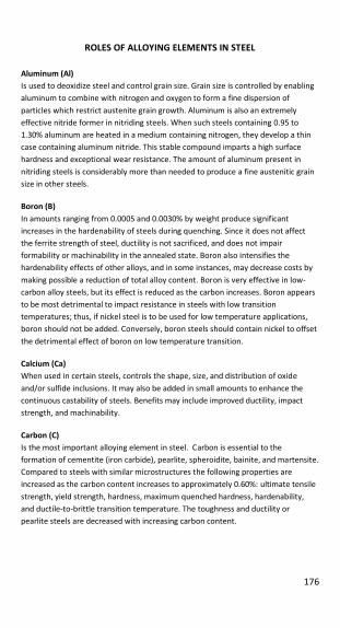
176
ROLES OF ALLOYING ELEMENTS IN STEEL
Aluminum (Al) Is used to deoxidize steel and control grain size. Grain size is controlled by enabling
aluminum to combine with nitrogen and oxygen to form a fine dispersion of
particles which restrict austenite grain growth. Aluminum is also an extremely
effective nitride former in nitriding steels. When such steels containing 0.95 to
1.30% aluminum are heated in a medium containing nitrogen, they develop a thin
case containing aluminum nitride. This stable compound imparts a high surface
hardness and exceptional wear resistance. The amount of aluminum present in
nitriding steels is considerably more than needed to produce a fine austenitic grain
size in other steels.
Boron (B) In amounts ranging from 0.0005 and 0.0030% by weight produce significant
increases in the hardenability of steels during quenching. Since it does not affect
the ferrite strength of steel, ductility is not sacrificed, and does not impair
formability or machinability in the annealed state. Boron also intensifies the
hardenability effects of other alloys, and in some instances, may decrease costs by
making possible a reduction of total alloy content. Boron is very effective in low-
carbon alloy steels, but its effect is reduced as the carbon increases. Boron appears
to be most detrimental to impact resistance in steels with low transition
temperatures; thus, if nickel steel is to be used for low temperature applications,
boron should not be added. Conversely, boron steels should contain nickel to offset
the detrimental effect of boron on low temperature transition.
Calcium (Ca) When used in certain steels, controls the shape, size, and distribution of oxide
and/or sulfide inclusions. It may also be added in small amounts to enhance the
continuous castability of steels. Benefits may include improved ductility, impact
strength, and machinability.
Carbon (C) Is the most important alloying element in steel. Carbon is essential to the
formation of cementite (iron carbide), pearlite, spheroidite, bainite, and martensite.
Compared to steels with similar microstructures the following properties are
increased as the carbon content increases to approximately 0.60%: ultimate tensile
strength, yield strength, hardness, maximum quenched hardness, hardenability,
and ductile-to-brittle transition temperature. The toughness and ductility or
pearlite steels are decreased with increasing carbon content.
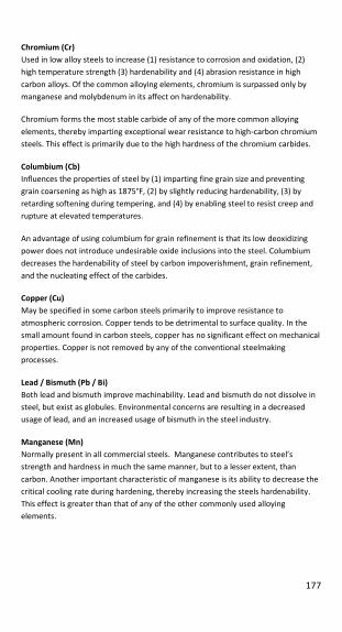
177
Chromium (Cr) Used in low alloy steels to increase (1) resistance to corrosion and oxidation, (2)
high temperature strength (3) hardenability and (4) abrasion resistance in high
carbon alloys. Of the common alloying elements, chromium is surpassed only by
manganese and molybdenum in its affect on hardenability.
Chromium forms the most stable carbide of any of the more common alloying
elements, thereby imparting exceptional wear resistance to high-carbon chromium
steels. This effect is primarily due to the high hardness of the chromium carbides.
Columbium (Cb) Influences the properties of steel by (1) imparting fine grain size and preventing
grain coarsening as high as 1875°F, (2) by slightly reducing hardenability, (3) by
retarding softening during tempering, and (4) by enabling steel to resist creep and
rupture at elevated temperatures.
An advantage of using columbium for grain refinement is that its low deoxidizing
power does not introduce undesirable oxide inclusions into the steel. Columbium
decreases the hardenability of steel by carbon impoverishment, grain refinement,
and the nucleating effect of the carbides.
Copper (Cu) May be specified in some carbon steels primarily to improve resistance to
atmospheric corrosion. Copper tends to be detrimental to surface quality. In the
small amount found in carbon steels, copper has no significant effect on mechanical
properties. Copper is not removed by any of the conventional steelmaking
processes.
Lead / Bismuth (Pb / Bi) Both lead and bismuth improve machinability. Lead and bismuth do not dissolve in
steel, but exist as globules. Environmental concerns are resulting in a decreased
usage of lead, and an increased usage of bismuth in the steel industry.
Manganese (Mn) Normally present in all commercial steels. Manganese contributes to steel’s strength and hardness in much the same manner, but to a lesser extent, than
carbon. Another important characteristic of manganese is its ability to decrease the
critical cooling rate during hardening, thereby increasing the steels hardenability.
This effect is greater than that of any of the other commonly used alloying
elements.
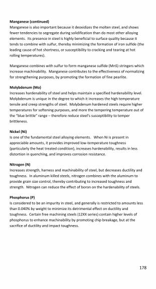
178
Manganese (continued) Manganese is also important because it deoxidizes the molten steel, and shows
fewer tendencies to segregate during solidification than do most other alloying
elements. Its presence in steel is highly beneficial to surface quality because it
tends to combine with sulfur, thereby minimizing the formation of iron sulfide (the
leading cause of hot shortness, or susceptibility to cracking and tearing at hot
rolling temperatures).
Manganese combines with sulfur to form manganese sulfide (MnS) stringers which
increase machinability. Manganese contributes to the effectiveness of normalizing
for strengthening purposes, by promoting the formation of fine pearlite.
Molybdenum (Mo) Increases hardenability of steel and helps maintain a specified hardenability level.
Molybdenum is unique in the degree to which it increases the high temperature
tensile and creep strengths of steel. Molybdenum hardened steels require higher
temperatures for softening purposes, and more the tempering temperature out of
the “blue brittle” range – therefore reduce steel’s susceptibility to temper brittleness.
Nickel (Ni) Is one of the fundamental steel alloying elements. When Ni is present in
appreciable amounts, it provides improved low-temperature toughness
(particularly the heat treated condition), increases hardenability, results in less
distortion in quenching, and improves corrosion resistance.
Nitrogen (N) Increases strength, harness and machinability of steel, but decreases ductility and
toughness. In aluminum killed steels, nitrogen combines with the aluminum to
provide grain size control, thereby contributing to increased toughness and
strength. Nitrogen can reduce the effect of boron on the hardenability of steels.
Phosphorus (P) Is considered to be an impurity in steel, and generally is restricted to amounts less
than 0.040% by weight to minimize its detrimental effect on ductility and
toughness. Certain free machining steels (12XX series) contain higher levels of
phosphorus to enhance machinability by promoting chip breakage, but at the
sacrifice of ductility and impact toughness.
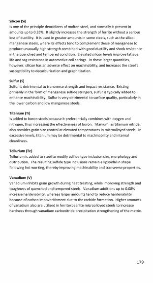
179
Silicon (Si) Is one of the principle deoxidizers of molten steel, and normally is present in
amounts up to 0.35%. It slightly increases the strength of ferrite without a serious
loss of ductility. It is used in greater amounts in some steels, such as the silico-
manganese steels, where its effects tend to complement those of manganese to
produce unusually high strength combined with good ductility and shock resistance
in the quenched and tempered condition. Elevated silicon levels improve fatigue
life and sag resistance in automotive coil springs. In these larger quantities,
however, silicon has an adverse effect on machinability, and increases the steel’s susceptibility to decarburization and graphitization.
Sulfur (S) Sulfur is detrimental to transverse strength and impact resistance. Existing
primarily in the form of manganese sulfide stringers, sulfur is typically added to
enhance machinability. Sulfur is very detrimental to surface quality, particularly in
the lower carbon and low manganese steels.
Titanium (Ti) Is added to boron steels because it preferentially combines with oxygen and
nitrogen, thus increasing the effectiveness of boron. Titanium, as titanium nitride,
also provides grain size control at elevated temperatures in microalloyed steels. In
excessive levels, titanium may be detrimental to machinability and internal
cleanliness.
Tellurium (Te) Tellurium is added to steel to modify sulfide type inclusion size, morphology and
distribution. The resulting sulfide type inclusions remain ellipsoidal in shape
following hot working, thereby improving machinability and transverse properties.
Vanadium (V) Vanadium inhibits grain growth during heat treating, while improving strength and
toughness of quenched and tempered steels. Vanadium additions up to 0.08%
increase hardenability, whereas larger amounts tend to reduce hardenability
because of carbon impoverishment due to the carbide formation. Higher amounts
of vanadium also are utilized in ferrite/pearlite microalloyed steels to increase
hardness through vanadium carbonitride precipitation strengthening of the matrix.

180
HEAT TREATING TERMS
Transformation Temperature the temperature at which a change in solid phase occurs. The heat treatment of
steel deals with those ranges of temperature which austenite forms upon heating
and transforms to ferrite (or to ferrite plus cementite) during cooling. The two
ranges are distinct (sometimes overlapping), but never coinciding. The limiting
temperatures of the ranges depend on the composition of the steel and the rate of
change in temperature, particularly during cooling.
The following symbols for critical temperatures are used for the heat treatment of
steel:
Ac1: The temperature at which austenite begins to form during heating.
Ac3: The temperature at which transformation of ferrite to austenite is
completed during heating.
Ar3: The temperature at which austenite begins to transform to ferrite (or to
ferrite plus cementite) during cooling.
Ar1: The temperature at which transformation of austenite to ferrite (or to
ferrite plus cementite) is complete during cooling.
Ms: The temperature at which the transformation of austenite to marten site
starts during cooling.
Mf: The temperature at which transformation of austenite to marten site
finished during cooling.
Annealing in general, the annealing process is the threefold completion of a heating cycle, a
holding period, and a controlled cooling cycle. Annealing may be used to achieve
the following results: to soften or alter the grain structure of steel; to enhance
formability, machinability or mechanical properties; or to relieve residual stresses.
The desired final results dictate which heat treating temperatures and cooling rates
are used. Thus, specific annealing cycles have become known by names
characteristic of the particular processes or end results. The most frequently used
of these processes are discussed below.
1. Subcritical Annealing (Also known as Process Annealing or Stress Relief
Annealing) consists of heating steel to a temperature approaching the lower
critical (Ac1) temperature. This represents the simplest form of annealing.
Its function is to reduce residual stress and hardness, and make minor
changes in microstructure. It is used frequently to facilitate cold shear-
ability. It may also be used between cold forming operations to reduce the
cold worked hardness and recrystallize the grain structure.
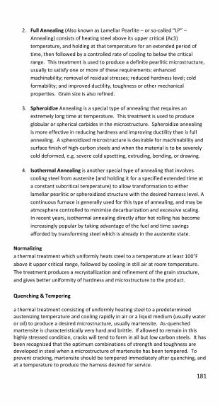
181
2. Full Annealing (Also known as Lamellar Pearlite – or so-called “LP” –
Annealing) consists of heating steel above its upper critical (Ac3)
temperature, and holding at that temperature for an extended period of
time, then followed by a controlled rate of cooling to below the critical
range. This treatment is used to produce a definite pearlitic microstructure,
usually to satisfy one or more of these requirements: enhanced
machinability; removal of residual stresses; reduced hardness level; cold
formability; and improved ductility, toughness or other mechanical
properties. Grain size is also refined.
3. Spheroidize Annealing is a special type of annealing that requires an
extremely long time at temperature. This treatment is used to produce
globular or spherical carbides in the microstructure. Spheroidize annealing
is more effective in reducing hardness and improving ductility than is full
annealing. A spheroidized microstructure is desirable for machinability and
surface finish of high-carbon steels and when the material is to be severely
cold deformed, e.g. severe cold upsetting, extruding, bending, or drawing.
4. Isothermal Annealing is another special type of annealing that involves
cooling steel from austenite (and holding it for a specified extended time at
a constant subcritical temperature) to allow transformation to either
lamellar pearlitic or spheroidized structure with the desired harness level. A
continuous furnace is generally used for this type of annealing, and may be
atmosphere controlled to minimize decarburization and excessive scaling.
In recent years, isothermal annealing directly after hot rolling has become
increasingly popular by taking advantage of the fuel and time savings
afforded by transforming steel which is already in the austenite state.
Normalizing a thermal treatment which uniformly heats steel to a temperature at least 100°F
above it upper critical range, followed by cooling in still air at room temperature.
The treatment produces a recrystallization and refinement of the grain structure,
and gives better uniformity of hardness and microstructure to the product.
Quenching & Tempering a thermal treatment consisting of uniformly heating steel to a predetermined
austenizing temperature and cooling rapidly in air or a liquid medium (usually water
or oil) to produce a desired microstructure, usually martensite. As-quenched
martensite is characteristically very hard and brittle. If allowed to remain in this
highly stressed condition, cracks will tend to form in all but low carbon steels. It has
been recognized that the optimum combinations of strength and toughness are
developed in steel when a microstructure of martensite has been tempered. To
prevent cracking, martensite should be tempered immediately after quenching, and
at a temperature to produce the harness desired for service.
182
Hardenability (Response to Heat Treatment) the physical property of steel which determines the depth of martensitic hardness
that can be induced by quenching from temperatures over 1330°F. The chemical
composition and austenitic grain size of the steel completely determine it
hardenability, with almost all of the elements making varying degrees of
contribution.
Hardenability should not be confused with hardness per se or with maximum
hardness. Whereas the as-quenched surface hardness of steel is primarily
dependent upon carbon content and cooling rate, the depth to which a certain
hardness level is maintained with a given quenching condition is a measure of
hardenability.
Jominy End Quench Hardenability Test a laboratory heat treating procedure for determining the hardenability of steel by
reproducing a range of specific quenching rates on a single test specimen. The test
is performed by heating a standardized test specimen above the upper critical
temperature, then quickly hanging the hot specimen in a fixture so that a column of
cold water impinges on the bottom end of the specimen. The test specimen is
progressively quenched to room temperature, and the decreasing hardness is
measured from its maximum value (near the quenched end of the specimen) at
regularly spaced intervals away from the quenched end. The harness
measurements are plotted as a function of distance away from the quenched end.
This plot is known as the steel’s hardenability band. The range of cooling rates on a
standard Jominy test specimen has been correlated to bar diameter size for both oil
and water quenchants.
DI (Ideal Diameter) The DI is an alternate method for predicting hardenability. DI represents the
maximum theoretical bar diameter that will harden at the center with at least 50%
martensite, when subjected to an “ideal” quench (e.g. Grossman quench severity in which H=infinity).
183
MECHANICAL PROPERTY TERMS
The following four mechanical properties are determined from a single uniaxial test
specimen pulled in tension to the point of fracture:
Ultimate Tensile Strength (also abbreviated as “Tensile Strength”) Ultimate tensile strength is expressed as the ratio of the maximum applied load to
the original cross sectional area. The maximum load is achieved at the onset of
localized “necking” of the test specimen. Thereafter, the required tensile load is continuously reduced until the specimen is elongated to fracture.
The tensile strength of hot rolled steel is dependent first on the strength of pure
iron. The overall strength of steel is increased in proportion to incremental
additions of the various alloying elements. Besides chemical content, tensile
strength of steel may be influenced its microstructure. For a given composition, the
following microstructures exhibit increasing tensile strength: pearlite, bainite,
martensite.
Yield Strength the amount of stress which produces a defined amount of permanent deformation
(e.g. 0.2% in 2” gage length) from otherwise elastic behavior. The term “yielding” refers to a stress state at which the rate of steel deformation is no longer
proportional to the rate of applied loading. Once the applied load is released, the
yielded steel no longer returns to it initially unstressed dimensions.
Elongation (also known as “EL”) Ductility is also measured in a tensile test by pre-stamping two gage marks (usually
spaced 2” to 8” apart) along the tensile specimen, prior to running the test.
Subsidized tensile specimens may evaluate elongation from 1” or 1.4” gage marks. Elongation is the increase in length over the initial standard gage length, and is
usually expressed as a percentage of the original gage length.
Reduction of Area (also known as “R. of A.” or “RA”) Another measurement of ductility represents the amount of “necking” (decrease in cross sectional area) which has taken place during a tensile test. Reduction of area
is measured after the tensile test specimen has pulled to the point of fracture, and
is usually expressed as a percentage of the original cross sectional area.
Ductility A description of the ability of steel to withstand plastic deformation (e.g. change
shape) without rupture. This is a vital property for users in the cold forming,
heading or cold drawn bar markets. Ductility may be thought of as the opposite of
brittleness. In hot rolled bars, ductility generally decreases with increased chemical
content, tensile strength, and/or coarser grain size. Ductility is commonly
measured by “elongation” and “reduction of area” in a standard tensile test.
184
Hardness a measure of a metal’s ability to resist plastic deformation, usually by indentation. Hardness is an indirect measure of the relative ultimate tensile strength of steel.
The two most common hardness tests in general use are the Brinell hardness test
and the family of Rockwel hardness tests.
In the Brinell test, a 10mm diameter steel ball is pressed into the steel sample
under a 3000kg load. The Brinell Hardness Number (BNH) correlates inversely with
the area of the spherical impression – the diameter of the indentation in measured,
and the corresponding BNH is read off a chart. Automated Brinell test equipment
measures the spherical impression and calculates direct readouts of BNH.
The Rockwell test presses either a cone-shaped diamond indentor or a 1/16” diameter steel ball into the steel sample under a 10 kg minor load. A major load of
60, 100 or 150 kg is then applied and released. The number on the Rockwell scale
inversely correlates the difference of indentor depths penetrated by the minor and
major loads.
Impact Toughness a measure of a metal’s ability to resist fracture under high-velocity loading from the
force of a single blow. The Charpy V-Notch test is the most common method for
testing impact toughness. A standard test specimen with a machined V-Notch is
placed into a fixture, and struck from behind the notch by a swinging pendulum of
standard weight (mass). Other types of impact tests modify the geometries of the
notches, e.g. U-Notch or Izod tests.
Impact toughness varies according to composition, microstructure, grain size, and
service temperature of the steel. The impact toughness of steel is known to
abruptly change from ductile to brittle failure, when the temperature falls below a
certain critical value. For this reason, whole series of impact tests are often carried
out over a range of expected service temperatures.
Brittle test specimens hardly slow down the pendulum, and therefore exhibit very
low impact resistance. A “tough” (or ductile) test sample absorbs much more energy by decreasing the pendulum’s velocity, and therefore exhibits greater impact toughness.
185
MICROSTRUCTURAL TERMS
Microstructure Microstructure refers to the quantity, size, shape and distribution of various phases
in the steel. It depends totally on the chemistry, hardenability, heat treatment, and
cooling rates employed. Ferrite, the purest form of iron in steel, is the softest and
lowest strength constituent with highest ductility. Martensite, a supersaturated
solution of carbon in iron, is the hardest and most brittle microstructure. The
controlled diffusion of carbon, which is managed by regulating the tempering time
and temperature, softens the quenched martensitic microstructure and improves
ductility. Slow cooling from high temperatures causes the carbon to precipitate out
as iron carbide (or cementite) which is a hard phase. A mixture of ferrite and
lamellar (or plate-like) cementite is called pearlite. If the pearlitic microstructure is
heated to approximately 1300°F, and held there for some time, a spheroidized
carbide structure emerges which consists of iron carbide plates that have coalesced
into spherical shapes. Microstructural bainite can be described as “feathery” carbide. The Microstructural appearance of martensite in an etched specimen does
not reveal structure of grain boundaries.
Austenite is a term applied to the solid solution of carbon in gamma (or face-
centered cubic) iron and is present in carbon steels when they are heated above the
Ac3 transformation temperature. “Restrained austenite” is austenite the remains in the microstructure after a part has been quenched from its austenizing
temperature. It is a softer Microstructural constituent. Tempered martensite has a
needle-like appearance with no grain boundary detail.
Grain Size A steel’s grain size usually is expressed as the average diameter, or as a numeric value representing the quantity of grains per unit area or volume. Two types of
grain size are commonly expressed: 1) “austenitic” (high temperature) grain size, as determined by the McQuaid-Ehn test; and 2) various forms of room-temperature
grain size which are called as-rolled, or ferritic/pearlitic grain size. Evaluation of
grain size is performed with a metallurgical microscope in accordance with ASTM E-
112. ASTM grain size is often reported as a number: ASTM #1 through #5 are
generally called “coarse grain”; ASTM #5 and higher numbers are generally
classified as “fine grain”.
Inclusions Nonmetallic inclusions are particles of various oxides and silicates which form
during steel melting and refining. These inclusions consist of oxidized material,
sulfides, aluminates, silicates or nitrides in various combinations and mixtures.
ASTM E-45 specifies various methods for classifying and reporting various types of
inclusions. Inclusions are inherent to normal steelmaking practice. They are chiefly
derived from the oxidizing reactions of the refining processes and the deoxidizing
materials added to the molten steel in the furnace. In the case of free-machining
steels, sulfur, phosphorus and/or lead/bismuth are deliberately added to form
inclusions. Some inclusions will elongate in the hot rolling direction, while others
will remain as relatively point type features. The resulting inclusions’ shapes are influenced by the hot mill rolling temperature and the inclusions’ melting points.
186
Segregation (Also known as Chemical Segregation or Alloy Segregation) A centerline condition in which the local chemical composition of the steel departs
from the average composition. The chemical segregation (expressed in weight
percent) along the centerline of a hot rolled bar is either “positive” (greater) or
“negative (smaller) compared to the bar’s average chemical composition. Segregation is a natural phenomenon associated with the solidification of steel.
In general, the metal that solidifies rapidly, and close to the mold wall forms a “chill zone” which has approximately the same chemical composition as the liquid metal
entering the mold. As the solidification rate decreases, the mechanism of
solidification is such that crystals of purer metal tend to solidify first; the first
crystals to form contain less carbon, manganese, phosphorus, sulfur and other
elements – than from the liquid steel from which they were formed. The remaining
liquid steel in enriched by these elements as they are continually rejected during
the solidification process. Thus, the last material to solidify contains the largest
amount of the rejected elements. In descending order, the following common
elements in steel tend to segregate: sulfur, phosphorus, carbon, silicon, and
manganese.
Decarburization Depletion of the nominal carbon content at the surface of a bar. The combination of
time and temperature in the reheat furnace enables oxygen in the atmosphere to
react with carbon at the surface of the steel. Surface carbon and furnace oxygen
combine to form carbon monoxide, leaving the steel surface partially or totally
depleted of carbon.

187
STEEL DEFECT TERMS
Seam Longitudinal surface crevices the contain scales and decarburization, usually
oriented perpendicular to the bar’s surface. Seams can vary in length from a few
inches to several feet, and generally are randomly found along the length and
around the circumference of a bar. Medium to large sized seams can be detected
with the naked eye, especially after the hot rolled bar surface has been descaled.
Magnetic and eddy current testing offer greater assurance of detecting seams. The
recommended stock removal to rid bars of seams is 0.001” per size for each 1/16” of bar diameter (non-resulfurized steel grades), or 0.0015” per side for each 1/16” of bar diameter (resulfurized steel grades).
Lap Longitudinal crevices that contain scale and decarburization, usually oriented at
least 30 degrees off radial, created by the folding over (but not welding) of steel
during hot working. The most frequent cause of laps is “overfill” during hot rolling, in which steel gets forced into the roll gap, folds over and gets rolled into the bar
surface during subsequent roll passes. Shorter laps can be caused by the steel
momentarily failing to fill out the pass as it goes through the mill. Laps are generally
the result of poor workmanship, and are independent of the steel grade.
Sliver Loose or torn segments of steel rolled onto the bar surface in a random distribution
of small, rolled-out point defects.
Overfill A protrusion on one or both sides of a hot rolled bar caused by the section being
too large for the roll pass during hot working. If the defect is on one side only, it is
usually referred to as being “off the hole”, indicating a guiding or other alignment problem. If not corrected at the source, overfill frequently leads to laps in
subsequent mill stands. Overfill can sometimes occur on the extreme front and
back ends of rolled bars because the billet is not experiencing a steady rolling state.
The front end is adjusted to the pass while the back end does not have sufficient
tension, due to a lack of trailing material. Such material needs to be discarded.
Scratch Longitudinal indentations usually running parallel to the rolling direction, caused by
mechanical rubbing of the bar on protrusions as it is processed. Mechanical
scratches vary from small, sharp defects to large, plowed-out gouges. The
distinguishing feature of a scratch is the absence of scale and decarburization
associated with it. Scratches may occur during hot rolling (called mill scratches) or
after hot rolling (usually called handling damage).
188
Flakes (Also known as Hydrogen Flakes) Short, discontinuous internal fissures in steel attributed to stresses produced by
localized transformation and decreased solubility of hydrogen during cooling after
hot working. In a fracture surface, flakes appear as bright silvery areas; viewed on
edge along an etched micro specimen, flakes appear as short, discontinuous cracks.
The term “snow flake” was originally applied to this condition, due to the glistening
appearance of the fracture surfaces in failed sections. With time, the term was
shortened to “flakes”. Normal steel mill practices provide methods to control material cooling from rolling temperatures to prevent the formation of hydrogen
flakes. The hydrogen content, bar diameter and the steel’s volumetric expansion/contraction characteristics during the transformation of austenite are
also strong factors in hydrogen flake formation for a given sheet.
Internal Unsoundness (Also known as Porosity or Center Looseness) A solidification defect carried through to the finished hot rolled product. It is
manifested as a longitudinal centerline feature in the bar which is associated with
the thermal contraction of the original as-cast dendritic condition. Gross center
looseness is considered to be the result of casting at temperatures much higher
than the inherent freezing temperature of the steel, followed by insufficient hot
working.
Center looseness is often called an “etching phenomenon”, wherein different orientations of grains (dendritic patterns) are preferentially attacked by the
etchant. This preferential acid attack reveals visible contrast in the micro specimen.
On macro etched transverse sections, unsoundness appears either as an etched-out
hole or remnants of dendritic structure.
Scale A high-temperature, gray-colored iron oxide layer which forms on the surface of a
hot rolled bar. Scale can be detrimental to the finished product, particularly if the
scale is rolled into the surface (rolled-in scale), or if it adheres tightly to the steel.
Up to three layers of high-temperature iron oxide scale can form on hot rolled steel
products. The relative amounts of these three oxide layers depend upon the length
of time the steel is exposed to atmospheric oxygen at a particular temperature
range.
Roll Mark Repeating patterns of “embossed” elevations or depressions. Elevations are caused by depressions or cavity flaws on the mill rolls. Depressions on the bars are caused
by pieces of foreign matter which have impacted into the rolls.
Burnt Steel A severe surface defect which occurs when intergranular oxidation weakens the
grain boundaries to the point where they can no longer support mechanically
induced rolling stresses. This condition may be caused by grain boundary melting,
or extreme hot shortness, and is usually attributed to excessively high heating
temperatures. If not detected within the first few rolling mill stands, burnt steel can
deform further and appear to be surface scabs in the finished product.
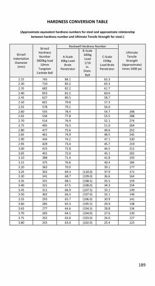
189
HARDNESS CONVERSION TABLE
(Approximate equivalent hardness numbers for steel and approximate relationship between hardness number and Ultimate Tensile Strength for steel.)
Brinell
Indentation
Diameter (mm)
Brinell Hardness
Number
3000kg load
10mm
Tungsten
Carbide Ball
Rockwell Hardness Number
Ultimate
Tensile
Strength
(Approximate)
times 1000 psi
A-Scale
60kg Load
Brale
Penetrator
B-Scale
100kg
Load
1/16
In. Diam.
Ball
C-Scale
150kg
Load Brale
Penetrator
2.25 745 84.1 65.3
2.30 710 83.2 63.3
2.35 682 82.2 61.7
2.40 653 81.2 60.0
2.45 627 80.5 58.7
2.50 601 79.8 57.3
2.55 578 79.1 56.0
2.60 555 78.4 54.7 298
2.65 534 77.8 53.5 288
2.70 514 76.9 52.1 274
2.75 495 76.3 51.0 264
2.80 477 75.6 49.6 252
2.85 461 74.9 48.5 242
2.90 444 74.2 47.1 230
2.95 429 73.4 45.7 219
3.00 415 72.8 44.5 212
3.05 401 72.0 43.1 202
3.10 388 71.4 41.8 193
3.15 375 70.6 40.4 184
3.20 363 70.0 39.1 177
3.25 352 69.3 (110.0) 37.9 171
3.30 341 68.7 (109.0) 36.6 164
3.35 331 68.1 (108.5) 35.5 159
3.40 321 67.5 (108.0) 34.3 154
3.45 311 66.9 (107.5) 33.1 149
3.50 302 66.3 (107.0) 32.1 146
3.55 293 65.7 (106.0) 30.9 141
3.60 285 65.3 (105.5) 29.9 138
3.65 277 64.6 (104.5) 28.8 134
3.70 265 64.1 (104.0) 27.6 130
3.75 262 63.6 (103.0) 26.6 127
3.80 255 63.0 (102.0) 25.4 123
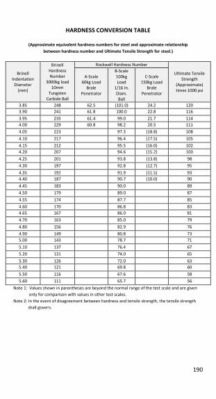
190
HARDNESS CONVERSION TABLE
(Approximate equivalent hardness numbers for steel and approximate relationship between hardness number and Ultimate Tensile Strength for steel.)
Brinell
Indentation
Diameter
(mm)
Brinell
Hardness
Number
3000kg load 10mm
Tungsten
Carbide Ball
Rockwell Hardness Number
Ultimate Tensile
Strength
(Approximate)
times 1000 psi
A-Scale 60kg Load
Brale
Penetrator
B-Scale
100kg Load
1/16 In.
Diam.
Ball
C-Scale 150kg Load
Brale
Penetrator
3.85 248 62.5 (101.0) 24.2 120
3.90 241 61.8 100.0 22.8 116
3.95 235 61.4 99.0 21.7 114
4.00 229 60.8 98.2 20.5 111
4.05 223 97.3 (18.8) 108
4.10 217 96.4 (17.5) 105
4.15 212 95.5 (16.0) 102
4.20 207 94.6 (15.2) 100
4.25 201 93.8 (13.8) 98
4.30 197 92.8 (12.7) 95
4.35 192 91.9 (11.5) 93
4.40 187 90.7 (10.0) 90
4.45 183 90.0 89
4.50 179 89.0 87
4.55 174 87.7 85
4.60 170 86.8 83
4.65 167 86.0 81
4.70 163 85.0 79
4.80 156 82.9 76
4.90 149 80.8 73
5.00 143 78.7 71
5.10 137 76.4 67
5.20 131 74.0 65
5.30 126 72.0 63
5.40 121 69.8 60
5.50 116 67.6 58
5.60 111 65.7 56
Note 1: Values shown in parentheses are beyond the normal range of the test scale and are given
only for comparison with values in other test scales.
Note 2: In the event of disagreement between hardness and tensile strength, the tensile strength
shall govern.
191
COMMON CONVERSION FACTORS
To Convert To → Multiplier ← To Convert To
Length Length Inch (in) 25.4 0.0394 Millimeter (mm)
Foot (ft) 30.48 0.0328 Centimeter (cm)
Yard (yd) 0.914 1.0936 Meter (m)
Mile (mi) 1.609 0.6214 Kilometer (km)
Area Area Square Inch 645.2 0.00155 Square Millimeter
Square Inch 6.452 0.155 Square Centimeter
Square Foot 0.0929 10.76 Square Meter
Volume Volume Cubic Inch 16.39 0.06102 Cubic Centimeter
Cubic Foot 0.02832 35.31 Cubic Meter
Force or Weight Force or Weight Pound (lb) 0.453597 2.205 Kilogram
Ton 0.907 1.102 Metric Ton
Stress Stress Pounds/square
inch (psi) 0.0703 14.22
Kilograms/square
cm
Pounds/square
inch (psi) 0.006895 145 Megapascal (MPa)
Kilopounds/square
inch (ksi) 6.895 0.145 Megapascal (MPa)
Mass Density Mass Density Pounds/Cubic Foot 1.602 0.6242 Grams/cubic cm
Temperature Temperature Fahrenheit (F) 0.555 x (F - 32) (1.8 x C) + 32 Celsius (C)

192
NOTES
BAR DATA HANDBOOK | AISI/SAE | Chemical Compositions and Metallurgical Data
8000 North County Road 225 East | Pittsboro, Indiana 46167 | (877) 683-2277 | f: (317) 892-7005
SECOND EDITION


