96
A DNV GL report commissioned by NSA March 2014 GOOD PRACTICES BARRIER MANAGEMENT IN OPERATION FOR THE RIG INDUSTRY
A DNV GL report commissioned by NSA
March 2014
GOOD PRACTICESBARRIER MANAGEMENT IN OPERATION FOR THE RIG INDUSTRY

As a response to this challenge, the members of the Operations and Environmental committee for Offshore Entrepreneurs at the Norwegian Shipowners’ Association decided to unify their knowledge and resources, and develop a project to raise the level and quality of barrier management in the rig companies.
The final product of the project is a document called “Barrier Management in Operation for rig industry, Good Practices”.
Barrier Management is not something that can be performed as a stand-alone activity. Barrier Management must be incorporated in all operation activities. However, it is essential to have a clear structure and understanding of what forms the basis for a good system.
The term Good Practices is used in the understanding that what is good practice depends on the context where it is used. The aim of the project is to provide a common understanding of the methodology and level of the work that is needed to establish an appropriate barrier management system.
Hanna Lee BehrensDIRECTOR SAFETY, ENVIRONMENT AND INNOVATIONNORWEGIAN SHIPOWNERS’ ASSOCIATION
The rig industry is getting more complex every year, every month and every day. However, the hazards we are facing are the same, and have to be managed in a proper way on a daily basis. The Macondo accident was an eye opener for the whole industry, and the Petroleum Safety Authority Norway challenged the industry on different levels. One challenge given was to strengthen the work on barrier management.
PREFACE


DNV GL – Report No. 2013-1622, Rev. 1 – www.dnvgl.com Page 1
Table of Contents
INTRODUCTION ........................................................................................................................... 3
Objective 3
Scope of work 4
Limitations 4
Target group 5
How to read this report 5
ABBREVIATIONS .......................................................................................................................... 6
1 RISK AND MAJOR ACCIDENTS .......................................................................................... 7
1.1 Hazard and hazardous events 8
1.2 Risk picture 11
2 THE RATIONALE BEHIND BARRIER MANAGEMENT ............................................................. 12
3 BARRIER TERMINOLOGY ................................................................................................ 14
3.1 Barrier function 15
3.2 Barrier element 17
3.3 Safety system and safety function 21
3.4 Safety critical element 22
3.5 Safety critical task 22
3.6 Performance shaping factors 25
4 BARRIER MANAGEMENT FRAMEWORK ............................................................................. 25
5 ESTABLISH AND IMPLEMENT BARRIER MANAGEMENT ....................................................... 32
5.1 Barrier analysis 32
5.2 Barrier strategy 37
5.3 Performance requirements 41 5.3.1 Performance requirements for operational barrier elements 46
5.4 Prevent degradation of barrier performance 52
5.5 Maintenance 55 5.5.1 Consequence classification 58
5.6 Managing operational barrier elements/safety critical tasks 58 5.6.1 Training and drills 60 5.6.2 Planning and execution of safety critical tasks 61
5.7 Assurance activities 63
5.8 Verification activities 64
6 MONITOR BARRIER PERFORMANCE ................................................................................. 67
6.1 Identify input data/indicators 68
6.2 Evaluate and communicate barrier status 70
6.3 The purpose and use of information about barrier status 72
7 BARRIER MANAGEMENT FROM DAY-TO-DAY ..................................................................... 74
7.1 Work Permit (WP) approval 75
7.2 Continuous improvement 76
7.3 Reporting and incident investigations 77

DNV GL – Report No. 2013-1622, Rev. 1 – www.dnvgl.com Page 2
8 KNOWLEDGE ABOUT BARRIER MANAGEMENT ................................................................... 79
9 REFERENCES ................................................................................................................ 85
APPENDIX A: MAPPING AND EVALUATION OF PERFORMANCE SHAPING FACTORS .............................. 86

DNV GL – Report No. 2013-1622, Rev. 1 – www.dnvgl.com Page 3
INTRODUCTION
The Norwegian Shipowners’ Association (NSA) has initiated the work of developing this report as means
to provide rig owners in Norway with a common understanding and approach on how to implement and
manage barriers in daily operation to prevent major accidents.
Guidelines and standards stating the requirements for barriers and major accident risk management are
well described by the Petroleum Safety Authorities (PSA) and other sources. The ways of compliance,
however, vary significantly from rig owner to rig owner.
The report is developed on behalf of, and with input from, the NSA’s member organizations. More
specifically, through a kick-off meeting and a two-day workshop the Operations and Environment
Committee (Drift og Miljø-utvalget, DMU) in NSA met to discuss and express their topics of concern,
challenges and needs of the industry. The meetings were facilitated by DNV GL who was also responsible
for capturing relevant input from the rig owners and developing the report. In addition, relevant
expertise in DNV GL has contributed to ensure that important topics have been addressed in a suitable
manner. This includes representatives from Asset & Safety Advisory Services, as well as Offshore Class.
Objective
The main objective of this report is to give readers an increased understanding of barrier management in
practice, with emphasis on implementation of solutions for the operational phase. The proposed solutions
are intentionally named “Good Practices” with the following reasoning;
The field of barrier management is constantly developing and in a rapid pace. Capturing everything that
is “best” would be impossible. In addition, different companies have different needs depending on their
maturity levels and focus areas within barrier management. Hence, what is best for one company may
not be the best for another. Consequently, it is here believed that the term “Best Practice” would be
misleading and it is acknowledged that challenges can be solved with different solutions.
Following the same logic, efforts have been made to balance between being too specific and too general
when recommending Good Practices. It is not this report’s intention to promote exclusive ways of
managing barriers, but instead provide hints and tips about how issues can be addressed. Companies
will be able to review general Good Practices and consider what they have in place, improvement areas,
and ways to go about for refining their barrier management practice. Another upside of being general is
that it allows room for interpretations. This creates debate in the industry, and from debate comes
increased learning. Thus, some room for interpretation is considered healthy.
Nevertheless, being overly general may in some cases foster confusion. This is the argument behind the
more specific solutions described in this report. While some confusion about barrier management is likely
to exist in several years to come, this report targets key areas which have been subject for confusion in
the last couple of years. This ranges from basic questions about what barriers are and how they are
identified, to more complex considerations regarding equipment classification. The report will inevitably
add some confusion, but hopefully remove more.
Finally, the rig industry has long traditions when it comes to managing safety and assets. This has
resulted in well-established routines for activities related to barrier management, such as maintenance,
training and processes for safe operation. Barrier management taps into such practices by providing a
more structured, integrated and systematic approach to managing major accident risk. Still, an
underlying message in this report encourages companies not to introduce new and additional systems,
but instead adapt and utilize their existing practices to accompany principles from barrier management.
Managing barriers must not become a time consuming “add-on”, subject to frustration and down
prioritization among already busy employees. Instead it must become an integrated part of managing
the installation.

DNV GL – Report No. 2013-1622, Rev. 1 – www.dnvgl.com Page 4
Scope of work
A main goal for this document is to provide guidance on barrier management for the operational phase.
For this to be successful it is a pre-requisite that the necessary preparations have been made. This refers
to a basis for implementation, such as knowing what should be considered as barriers and how they
must perform to reduce risk. First when the basis is in place, suitable solutions for managing barriers in
operations can be implemented. The scope in this report reflects this principle, and can be summarized
as following:
- Definitions of relevant terminology, such as those related to risk, major accidents and barriers.
The purpose is to create a common language in the industry for how to understand barriers and
accident scenarios.
- Explanation of the rationale, or purpose, of barrier management as means to prevent major
accidents. The purpose is to explain how barrier management can contribute to reduce the
uncertainty of whether major accident risk is managed in operations.
- Framework, including a process, for implementing barrier management solutions in operations
and how barrier performance can be maintained in operations. The purpose is to provide a
description of methods, tools and activities for systematic implementation and performance
management of barriers.
- Explain how the framework can be implemented and used in operations with use of relevant
examples, such as maintenance and training. The purpose is to provide guidance on
improvement areas and how existing systems and practices can be adapted to accommodate
barrier management.
Limitations
The following limitations apply: - Barrier management interfaces with several other aspects related to management of safety,
environment, and asset risk. Examples are safety culture, operational risk management, and
organizational learning, to name a few. All these areas are highly relevant for managing risk, and
it is acknowledged that barrier management alone is not a complete solution of preventing major
accidents. Nevertheless, the scope of this report is limited to concern barrier management.
- Trying to cover everything about barrier management in one document would make for an
unpractical and excessively long report. The content of this report captures how to further
improve the industry’s status quo by addressing key topics and challenges experienced by
various stakeholders.
- The report does not include prescriptive recommendations on how barrier management should
be operationalized. Rig owners organizations vary in terms of systems and processes in place,
type of rigs, resources available, and barrier management maturity level. Instead
recommendations are developed to target the average rig owner. In cases where rig owners are
known to be similar, more specific recommendations are made where found relevant. In cases
where there are more variations, the recommendations are made on a more general level.
- Objective and scope of work is first and foremost relevant for Norwegian regulations. The
challenges related to moving rigs between shelves with different regulatory regimes are
acknowledged, but out scope. The report will however provide useful information for how to
comply with Norwegian regulations when moving a rig from e.g. the UK Continental Shelf onto
the Norwegian Continental Shelf.
- This report does not describe how requirements relevant to classification societies support
barrier management e.g different survey arrangements will give valuable information about
integrity of barriers on a rig.

DNV GL – Report No. 2013-1622, Rev. 1 – www.dnvgl.com Page 5
Target group
This report targets the rig owners’ management level, both onshore and offshore. Its relevance is therefore highest for managers, discipline leads, and process owners within operations, asset, HSE and HR.
How to read this report
For educational purposes, the report follows a certain structure and logic: - Frequent use of examples to accommodate and improve the reader’s understanding of various
topics. Examples are typically found in tables, figures and diagrams.
- Text boxes are used to highlight important content:
- Blue boxes are used for Good Practices. These have individual numbers for easy
referencing, tracking and overview.
- Green boxes for key definitions.
- Grey boxes for relevant requirements.
- In each text box, the Good Practice, definition or requirement is indicated with text in italics
format. Additional explanation is indicated with text in normal font under “Comments:”.
- The text boxes make it easy to re-visit the most important topics after having read the report or
selected chapters of particular interest.
DNV GL – Report No. 2013-1622, Rev. 1 – www.dnvgl.com Page 6
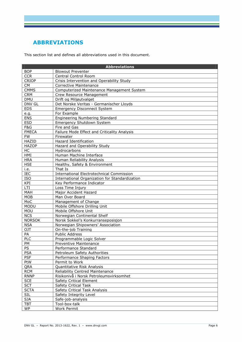
ABBREVIATIONS
This section list and defines all abbreviations used in this document.
Abbreviations
Abbreviations
BOP Blowout Preventer
CCR Central Control Room
CRIOP Crisis Intervention and Operability Study
CM Corrective Maintenance
CMMS Computerized Maintenance Management System
CRM Crew Resource Management
DMU Drift og Miljøutvalget
DNV GL Det Norske Veritas - Germanischer Lloyds
EDS Emergency Disconnect System
e.g. For Example
ENS Engineering Numbering Standard
ESD Emergency Shutdown System
F&G Fire and Gas
FMECA Failure Mode Effect and Criticality Analysis
FW Firewater
HAZID Hazard Identification
HAZOP Hazard and Operability Study
HC Hydrocarbons
HMI Human Machine Interface
HRA Human Reliability Analysis
HSE Healthy, Safety & Environment
i.e. That Is
IEC International Electrotechnical Commission
ISO International Organization for Standardization
KPI Key Performance Indicator
LTI Loss Time Injury
MAH Major Accident Hazard
MOB Man Over Board
MoC Management of Change
MODU Mobile Offshore Drilling Unit
MOU Mobile Offshore Unit
NCS Norwegian Continental Shelf
NORSOK Norsk Sokkel’s Konkurranseposisjon
NSA Norwegian Shipowners’ Association
OJT On-the-job Training
PA Public Address
PLC Programmable Logic Solver
PM Preventive Maintenance
PS Performance Standard
PSA Petroleum Safety Authorities
PSF Performance Shaping Factors
PtW Permit to Work
QRA Quantitative Risk Analysis
RCM Reliability Centred Maintenance
RNNP Risikonivå i Norsk Petroleumsvirksomhet
SCE Safety Critical Element
SCT Safety Critical Task
SCTA Safety Critical Task Analysis
SIL Safety Integrity Level
SJA Safe-job-analysis
TBT Tool-box-talk
WP Work Permit
DNV GL – Report No. 2013-1622, Rev. 1 – www.dnvgl.com Page 7
1 RISK AND MAJOR ACCIDENTS
Offshore drilling involves significant risk. However, where there is no risk there is also no reward.
Examples could be:
- A rig that never leaves the dock,
- a plane that never takes off the runway, or
- a train that never leaves the station
of which none will be able to collect any rewards. The purpose of managing risk is therefore not to
eliminate the risk itself, but to understand and control it so that rewards can be maximized and losses
minimized. The purpose of this chapter is to describe the concept of risk and nature of accidents.
Risk is a complex and abstract term, but is mostly thought of as a function of the probability and
consequence associated with an undesired event. Put differently, risk is the combined answer to three
questions (Rausand, 2011):
(1) What can go wrong?
(2) What is the probability of that happening? and;
(3) What are the consequences?
Another perspective is to address risk as the degree or effect of uncertainty on objectives (ISO 31000).
So, if the goal (i.e. objective) is to have no accidents, risk refers to the uncertainty of whether this goal
is achievable. Thus, one of the purposes of risk management is to predict and reduce this uncertainty.
Risk Risk can be defined as the combination of the probability of an [hazardous] event and its consequence (ISO Guide 73).
Several definitions of major accident exist. Although somewhat different, they all have in common that
they refer to large scale consequences, in terms of impact on life, property and the environment. They
also indicate that the consequences may be immediate or delayed, suggesting that there is a potential
for escalation. Occupational accidents, in comparison, have smaller consequences with minimum
escalation potential.
Major accident A major accident is defined as an acute incident, such as a major discharge/emission or a fire/explosion, which immediately or subsequently causes several serious injuries and/or loss of human life, serious harm to the environment and/or loss of substantial material assets (ref. www.ptil.no).
Comment:
Accident categories to consider on the NCS are indicated in PSA’s “RNNP and major accident risk”
where the following categories are identified:
Leaks of flammable gas or liquids; either ignited or un-ignited
Well control incidents; either ignited or un-ignited
Fire/explosion in other areas; could be in critical areas of the rig causing escalation (e.g.
machinery fire/explosion leading to loss of position control, resulting in drift off when
operating on DP)
Collisions and other structural damage; including ship collision and dropped objects.

DNV GL – Report No. 2013-1622, Rev. 1 – www.dnvgl.com Page 8
Whether or not an event or incident is considered to have major accident potential depends on the
degree of expected losses and harm against a set of consequence categories. These categories have pre-
defined impact levels and intervals with respect to loss of life, harm to the environment, damage to
assets and depreciation of reputation. For example, loss of life can be measured in potential number of
fatalities, harm to the environment in barrels or cubic meter of emission/spill, and damage to asset in
financial loss.
Good practice 1 Define impact levels and intervals for potential major accident consequence categories. Comments: For the major accident categories as described in definition of Major Accidents above, PSA outlines a requirement in Management Regulations, Section 9 stipulating that acceptance criteria is available for the following risk parameters:
a) Risk to loss of lives b) Risk to loss of main safety functions;
a. prevent escalation, b. maintain global structural integrity, c. protection of safety critical functions (e.g. control room, muster area, temporary
refuge, emergency equipment etc.) d. Escape routes and evacuation facilities
c) Acute pollution from the offshore facility d) Damage to 3rd party (personnel)
Absolute values for acceptance criteria is not given, however guidance of parameters to use when
establishing these can be found in NORSOK Z-013.
1.1 Hazard and hazardous events
Managing major accident risk is about controlling hazards which have a potential of realizing hazardous
events with subsequent consequences defined as major accidents (see definition of major accident).
These hazards are sometimes referred to as major accident hazards, and hazardous events can
sometimes be referred to as intermediate, top, or central critical event.
Hazard Potential for human injury, damage to the environment, damage to property, or a combination of these (ISO 13702).
Hazardous event
Incident which occurs when a hazard is realized (NORSOK Z-013; ISO 13702).
In the oil and gas industry, potential sources of harm (i.e. hazards) can be explained by eight basic
forms of energy (see Figure 1-1). Several (or all) of these energy forms can be involved when
performing an operation. If control of the energy is lost, this may realize the hazard and cause a
hazardous event to occur. Using the diagram in identifying energy forms involved in activity / design
feature is found to be an effective tool for identifying hazards and consequences as part of hazard
identification (HAZID) on all detail levels. The model can be adopted for preparation of a HAZID for a
QRA as well as for performing an operational task like “storage of a container in a not normal location”.

DNV GL – Report No. 2013-1622, Rev. 1 – www.dnvgl.com Page 9
Figure 1-1: Eight basic energy forms
Major accident scenarios refers to event sequences starting from triggering events realizing one or
several hazards, resulting in hazardous events which ultimately causes large scale consequences.
Example: For the case of drilling into the reservoir section of a well. A significant hazard (i.e. energy
forms) is the formation pressure which needs to be controlled to prevent unintentional flow, or influx,
from the formation and into the wellbore. If not controlled, a small influx may develop into a well kick
and thereby “realizing” the hazard, causing a hazardous event to occur. Well kicks can be considered a
hazardous event since, if allowed to escalate, it can cause a blowout. A blow out commonly accepted a
major accident with potentially large-scale consequences, such as spills to the environment and
explosions (if ignited) with subsequent loss of lives.
Prevent
Mitigate
Movement
Chemical
Radiation
Electricity
Gravity
Temperature
Biological
Pressure

DNV GL – Report No. 2013-1622, Rev. 1 – www.dnvgl.com Page 10
Table 1-1: Examples of hazards and hazardous events representing different major accident
scenarios
Major accident hazard
Hazardous event Scenario
Formation pore pressure
Shallow gas blowout
Blowout Blowout at drill floor
Underground blowout
Topside blowout
Hydrocarbons in mud
Fire and explosion in mud process area
Fire related to drilling
Fire in shale-shaker area
Fire and explosion in well test area
H2S in formation H2S release Toxic Release
Maritime traffic High energy ship collision Ship collision
Helicopter transport Helicopter crash onto installation Helicopter Crash
Accommodation utilities
Fire and smoke in accommodation
Fire/Explosion (not related to drilling)
Helicopter transport Helifuel fire
Normal operation
Fire and explosion in engine compartment
Fire/explosion in other areas on rig without fixed firefighting equipment
Fire/explosion in other areas on rig with fixed firefighting equipment
Power generation Fire/explosion in main generator room
Fire in emergency generator room
Position keeping Critical loss of position (drive-off / drift-off), not relevant for jack-ups
Loss of position
Jacked-up while drilling
Loss of structural integrity Toppling
Punch through
Ballasting / buoyancy
Loss of buoyancy Capsize
Loss of stability
Transit Loss of manoeuvring ability during transit Loss of control in
transit Collision during transit
Jacking operation Loss of control while jacking (only relevant for jack-ups) Jacking failure
DNV GL – Report No. 2013-1622, Rev. 1 – www.dnvgl.com Page 11
1.2 Risk picture
Understanding the risk picture within the activity is an important factor of manage, avoiding or
minimizing the risk exposure.
Management regulation, section 16 “The responsible party shall ensure that analyses are carried out that provide the necessary basis for making decisions to safeguard health, safety and the environment.” Management regulations, section 17
“Risk analyses shall be carried out to identify and assess contributions to major accident and environmental risk, as well as ascertain the effects various operations and modifications will have on major accident and environmental risk.” “Emergency preparedness analyses shall be carried out and be part of the basis for making decisions when e.g. defining hazard and accident situations, and […]selecting and dimensioning emergency
preparedness measures.” Comments: NORSOK Z-013 can normally be used to fulfil the requirements for risk analyses and emergency preparedness analyses.
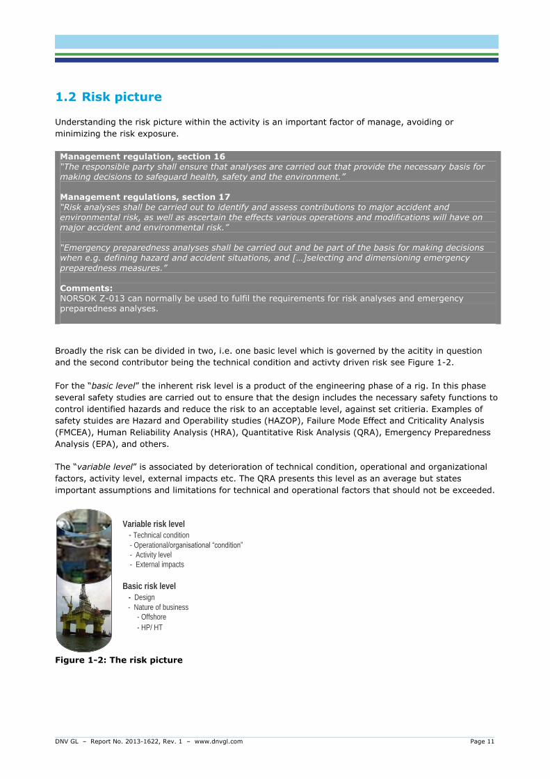
Broadly the risk can be divided in two, i.e. one basic level which is governed by the acitity in question
and the second contributor being the technical condition and activty driven risk see Figure 1-2.
For the “basic level” the inherent risk level is a product of the engineering phase of a rig. In this phase
several safety studies are carried out to ensure that the design includes the necessary safety functions to
control identified hazards and reduce the risk to an acceptable level, against set critieria. Examples of
safety stuides are Hazard and Operability studies (HAZOP), Failure Mode Effect and Criticality Analysis
(FMCEA), Human Reliability Analysis (HRA), Quantitative Risk Analysis (QRA), Emergency Preparedness
Analysis (EPA), and others.
The “variable level” is associated by deterioration of technical condition, operational and organizational
factors, activity level, external impacts etc. The QRA presents this level as an average but states
important assumptions and limitations for technical and operational factors that should not be exceeded.
Figure 1-2: The risk picture
Basic risk level
- Design
- Nature of business
- Offshore
- HP/ HT
Variable risk level
- Technical condition
- Operational/organisational“condition”
- Activity level
- External impacts
DNV GL – Report No. 2013-1622, Rev. 1 – www.dnvgl.com Page 12
A good understanding of the risk picture is vital in order to control hazards and prevent accidents. The
risk analysis is therefore a key document and natural starting point when working to manage risk in
operation. The main results and recommendations from the risk analyses should therefore be known to
decision takers both onshore and offshore a rig.
Good practice 2 Decision makers in the company, both onshore and offshore, should know how and when the QRA (plus other risk assessments) can be used to make risk informed decisions.
Comments: Understanding the risk picture for a rig is imperative for managing major accident risk in planning phase as well as in daily operations. I.e. the risk assessment can be used to identify main risk drivers for a given activity, a specific area on the installation etc. Furthermore, there will be assumptions in the risk assessment related to operational parameters such as activity level of e.g. lifting, number of and type of well activities, duration of well tests, manning level and distribution, which are influencing
the risk picture independent of the barrier status and performance.
2 THE RATIONALE BEHIND BARRIER MANAGEMENT
Understanding how major accidents occur and how they differ from occupational accidents is an
important part of barrier management. The risk of occupational accidents will almost always be
expressed in terms of medium to high probability and medium to low consequence. They occur relatively
often, especially compared to major accidents, and their consequences are usually low (sprained ankle,
cut in the finger etc.). Major accidents, on the other hand, occur relatively seldom. When they do occur,
however, they have large impacts, and have greater potential for escalation than occupational hazards.
Expressed as a risk, major accidents are by definition low-probability / high-consequence events.
One of the reasons why major accidents are rare events is due to the number of safety measures in
place. The question may then be: If major accidents occur so rarely, why do they require so much
attention? The answer is found in the uncertainty aspect of major accident risk. Major accidents are
complicated by nature and hard to predict. They involve a complex risk picture, multi-linear chain of
events, failure in several safety features, and with a potential for uncontrolled escalation. So, if a risk
analysis predicts a major accident to occur one time in a hundred years, it is hard to tell whether this
happens tomorrow, in fifty years or in a hundred. Consequently, management of major accident risk
requires good systems which captures this complexity and reduces uncertainty. This is the main
objective, or rationale, behind barrier management. It allows operators to prioritize important safety
measures related to technology and operation, so that the risk of major accidents can be reduced.
Occupational accidents, in contrast, have single-linear event chains with little or no potential for
escalation.
The oil and gas industry has a long tradition of measuring safety risk with parameters suitable for
occupational accidents (e.g. Loss-Time-Injury, LTI). Unfortunately, this has led people to believe that the
same parameters can be used as indicators for major accident risk. Lessons learned from accident
investigations reveals that due to their different nature, occupational accidents and major accidents
require different risk management approaches.
Good practice 3 Personnel on all levels in the organization know the difference between occupational accidents and major accidents, and why they require different risk management approaches.
DNV GL – Report No. 2013-1622, Rev. 1 – www.dnvgl.com Page 13
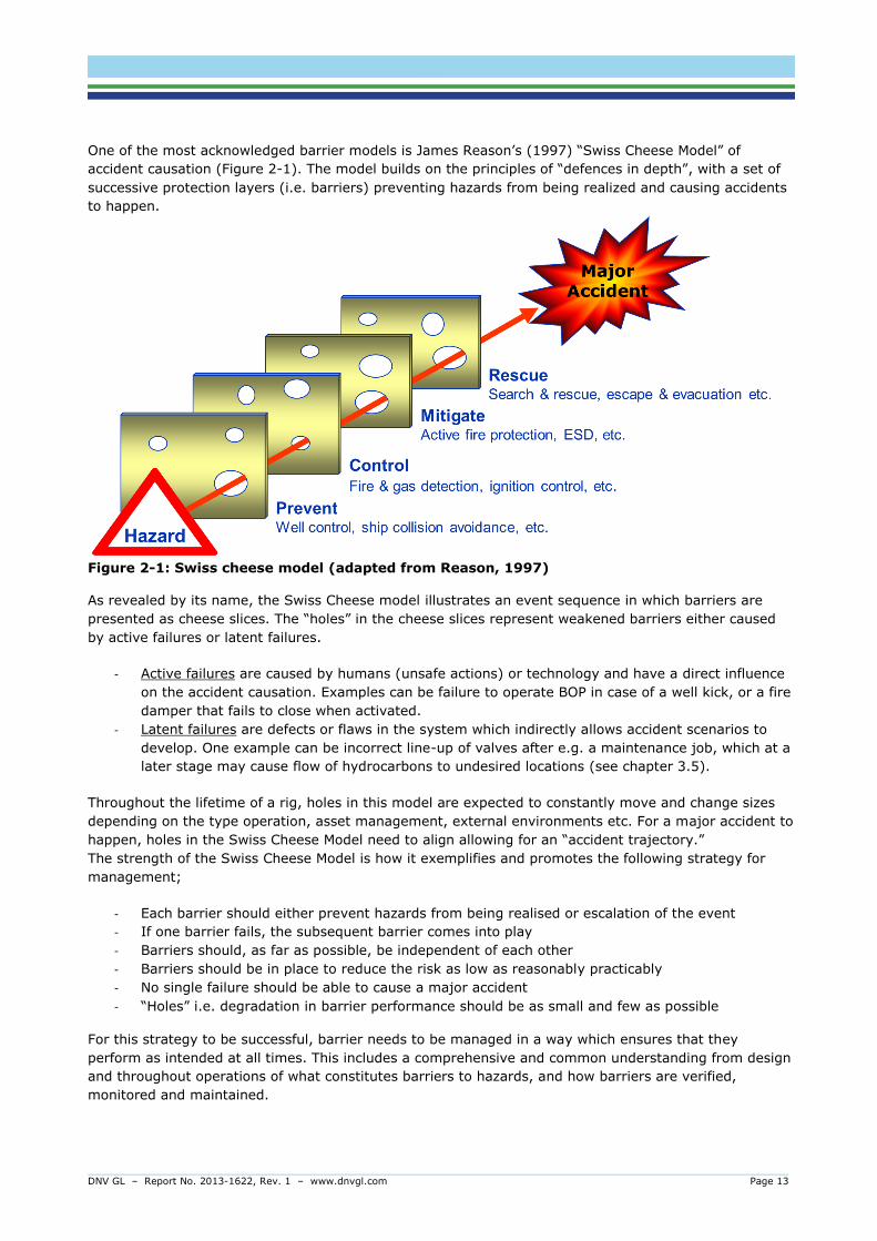
One of the most acknowledged barrier models is James Reason’s (1997) “Swiss Cheese Model” of
accident causation (Figure 2-1). The model builds on the principles of “defences in depth”, with a set of
successive protection layers (i.e. barriers) preventing hazards from being realized and causing accidents
to happen.
Figure 2-1: Swiss cheese model (adapted from Reason, 1997)
As revealed by its name, the Swiss Cheese model illustrates an event sequence in which barriers are
presented as cheese slices. The “holes” in the cheese slices represent weakened barriers either caused
by active failures or latent failures.
- Active failures are caused by humans (unsafe actions) or technology and have a direct influence
on the accident causation. Examples can be failure to operate BOP in case of a well kick, or a fire
damper that fails to close when activated.
- Latent failures are defects or flaws in the system which indirectly allows accident scenarios to
develop. One example can be incorrect line-up of valves after e.g. a maintenance job, which at a
later stage may cause flow of hydrocarbons to undesired locations (see chapter 3.5).
Throughout the lifetime of a rig, holes in this model are expected to constantly move and change sizes
depending on the type operation, asset management, external environments etc. For a major accident to
happen, holes in the Swiss Cheese Model need to align allowing for an “accident trajectory.”
The strength of the Swiss Cheese Model is how it exemplifies and promotes the following strategy for
management;
- Each barrier should either prevent hazards from being realised or escalation of the event
- If one barrier fails, the subsequent barrier comes into play
- Barriers should, as far as possible, be independent of each other
- Barriers should be in place to reduce the risk as low as reasonably practicably
- No single failure should be able to cause a major accident
- “Holes” i.e. degradation in barrier performance should be as small and few as possible
For this strategy to be successful, barrier needs to be managed in a way which ensures that they
perform as intended at all times. This includes a comprehensive and common understanding from design
and throughout operations of what constitutes barriers to hazards, and how barriers are verified,
monitored and maintained.
DNV GL – Report No. 2013-1622, Rev. 1 – www.dnvgl.com Page 14
3 BARRIER TERMINOLOGY
One way of managing risk is to implement safety barriers with purpose of preventing and mitigating
hazardous events.
Barrier Barriers refer to measures established with an explicit purpose to (1) prevent a hazard from being realized, or (2) to mitigate the effects of a hazardous event.
To be able to manage barriers it is essential to have a common understanding of what constitutes a
barrier. The way a company defines barriers and other associated terms ultimately determines what is
identified as barriers to be managed. Several definitions are already made available by regulatory bodies
(e.g. the PSA), national standards (e.g. NORSOK) and others. While these can be applied, care must be
taken when adopting them. For example, they may origin from ideas and perspectives not necessarily in
line with individual company needs.
The purpose behind a selected set of definitions, such as barrier- functions and -elements, is to make
sense of the barrier concept. Consequently, the definitions need to be coherent and specific. A common
pitfall is that definitions allow too much room for interpretation, and thus they fail to serve their purpose.
Furthermore, avoid mixing up the terms and definitions of safety systems, safety functions etc. with
those used to explain the concept of barriers (e.g. barrier element and -function). While all terms may
be applied, if it is not made clear how they relate to each other, this may be a source of unnecessary
confusion.
This chapter presents a set of coherent definitions and examples of what they refer to in real life. It also
discusses the similarities, differences and relationships between different terms. The definitions are
based on a review of available definitions, comments and feedback from rig companies, and industry
experience. Efforts have been made to capture relevance against expectations from regulatory bodies.
Good practice 4 Establish company definitions of barrier function, barrier elements and other associated terms required to explain the concept of barriers.
From a risk perspective, the notion of barriers being either preventive or mitigating translates into
reducing the probability and consequence of a hazardous event. This can be illustrated through barrier
diagrams, such as Bow-Tie (see Figure 3-1).

DNV GL – Report No. 2013-1622, Rev. 1 – www.dnvgl.com Page 15
Figure 3-1: Bow-Tie barrier diagram
3.1 Barrier function
As described in the definition of barriers, barriers are intentionally established (i.e. implemented) with an
explicit, safety related purpose in mind. The purpose, or role, of a barrier is referred to as a barrier
function. It can easily be defined by answering two simple questions about a barrier:
- Purpose: Why is it necessary?
- Role: How does it work?
For example; drilling fluid, or mud, prevent well kicks (why; the purpose) by exerting hydrostatic
pressure (how; the role). Another example; the blowout preventer, or BOP, prevents blowouts
(obviously) by shutting in or sealing off the well.
Barrier function The purpose or role of a barrier.
To fully understand how barrier functions work it is useful to separate between main- and sub-barrier
functions. The concept of barrier main- and sub-functions can be used to explain how different barriers
alone or together work to prevent and/or mitigate hazardous events.
The purpose of a barrier represents the barrier main-function which, if successfully realized, should have
a direct and significant effect on the hazard and/or event sequence. Examples are “prevent blowout”,
“maintain position” and “reduce fire load” (see Table 3-1).
Barrier sub-functions represent the roles performed by various barriers that are necessary to realize the
barrier main-function. Examples of sub-barrier functions are “detect kick”, “shut in well”, and “circulate
out kick” – all which are required to realize the barrier main-function “prevent blowout”. If one or several
of the barrier sub-functions fail, the barrier main-function may be potentially weakened or lost. To
exemplify, it may be futile to shut in the well if the kick is detected too late.
DNV GL – Report No. 2013-1622, Rev. 1 – www.dnvgl.com Page 16
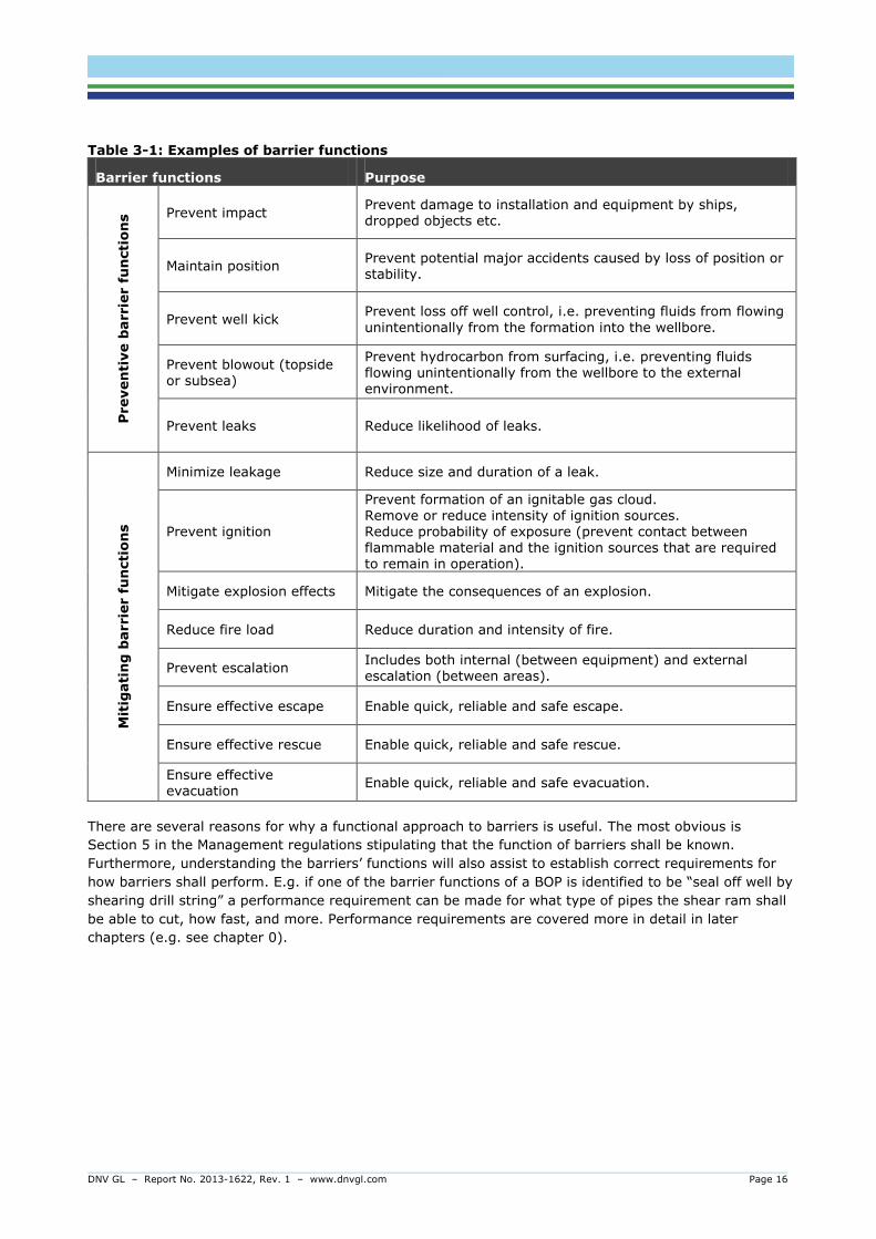
Table 3-1: Examples of barrier functions
Barrier functions Purpose
Preven
tive b
arrie
r f
un
cti
on
s Prevent impact
Prevent damage to installation and equipment by ships, dropped objects etc.
Maintain position Prevent potential major accidents caused by loss of position or stability.
Prevent well kick Prevent loss off well control, i.e. preventing fluids from flowing
unintentionally from the formation into the wellbore.
Prevent blowout (topside or subsea)
Prevent hydrocarbon from surfacing, i.e. preventing fluids flowing unintentionally from the wellbore to the external environment.
Prevent leaks Reduce likelihood of leaks.
Mit
igati
ng
barrie
r f
un
cti
on
s
Minimize leakage Reduce size and duration of a leak.
Prevent ignition
Prevent formation of an ignitable gas cloud. Remove or reduce intensity of ignition sources. Reduce probability of exposure (prevent contact between flammable material and the ignition sources that are required to remain in operation).
Mitigate explosion effects Mitigate the consequences of an explosion.
Reduce fire load Reduce duration and intensity of fire.
Prevent escalation Includes both internal (between equipment) and external escalation (between areas).
Ensure effective escape Enable quick, reliable and safe escape.
Ensure effective rescue Enable quick, reliable and safe rescue.
Ensure effective evacuation
Enable quick, reliable and safe evacuation.
There are several reasons for why a functional approach to barriers is useful. The most obvious is
Section 5 in the Management regulations stipulating that the function of barriers shall be known.
Furthermore, understanding the barriers’ functions will also assist to establish correct requirements for
how barriers shall perform. E.g. if one of the barrier functions of a BOP is identified to be “seal off well by
shearing drill string” a performance requirement can be made for what type of pipes the shear ram shall
be able to cut, how fast, and more. Performance requirements are covered more in detail in later
chapters (e.g. see chapter 0).

DNV GL – Report No. 2013-1622, Rev. 1 – www.dnvgl.com Page 17
3.2 Barrier element
A wide range of systems, structures, personnel and tasks are responsible for realizing (i.e. performing)
various barrier functions. Such measures are referred to as technical or operational barrier elements.
Barrier element Technical, operational or organisational measures which alone or together realize one or several barrier functions.
Comment:
“Realize” means performing barrier functions when required.
For practical reasons, such as identifying and managing barrier elements, it is necessary to further define
what is meant by technical, operational and organisational measures. Drilling rigs and ships are equipped
with a wide range of systems, structures and other design features which have barrier functions. This is
referred to as technical barrier elements.
Technical barrier element Engineered systems, structures, or other design features which realize one or several barrier functions.
Technical barrier elements can further be divided into two main categories – those that do and those
that do not alter shape state or condition in order to perform a barrier function. The former is commonly
referred to as active or functional barrier elements, while the latter is often called passive or structural
barriers. Active barriers can be characterized by being dependent on actions of an operator, a control
system and/or some energy sources to perform their functions. Passive barriers refer to measures
integrated into the design of the platform or vessel, and do not require operator actions, energy sources
or control systems to perform their functions.
Examples include:
- Active / functional: Fire and gas detectors, fire dampers, sprinklers, emergency shutdown
valves, PA, communication equipment, BOP, choke and kill system, etc.
- Passive / structural: Fire and explosion walls, casing, cements, 500m safety zone, passive
fire protection, drains, escape routes, temporary refuge etc.
There is no prescriptive list or overview available which pre-defines what the technical barrier elements
are, and on which detail level they shall be identified. What constitute a barrier should be based
assessments of the hazards involved with the rig’s technology-, operation- and regulatory- regime (see
barrier analysis in chapter 5.1). The levels of detail on which technical barrier elements are identified
depend much on the systems in question. Some systems are large and complex, while others are simpler
and made up of fewer parts. For technical barrier elements under the category of “active fire protection”,
a suitable detail level can be:
- Fire water supply (pumps and associated equipment)
- Fire water ring main and distribution pipework
- Fire hydrants, hoses and fire water monitors
- Water spray/ foam deluge systems
- Water mist systems
- Helideck and refuelling fixed foam system
- Dual agent skids for the helideck (powder and foam)
- Aragonite extinguishing systems
DNV GL – Report No. 2013-1622, Rev. 1 – www.dnvgl.com Page 18
Technical systems can be broken down to the tiniest screw. Thus, a second important factor when
deciding on detail level is for which purpose barrier elements are identified. Knowing the barrier
elements function, requirements for performance, and how they can be weakened or impaired, are
important objectives for identifying barriers which should be considered when determining a preferred
detail level.
Some barrier functions are automatically realized by technical barrier elements performing according to a
predefined logic when triggered. Other barrier functions are partly automatic or fully manual and rely on
operators to perform certain tasks. Such tasks are referred to as operational barrier elements.
Examples of operational barrier elements in a secondary well control incident are (note: this is a high
level example for illustration purposes):
- To monitor kick detection indicators on various displays and gauges (continuous),
- To perform flow checks and records pit gain in case a kick is suspected
- If a kick is confirmed; to close in the well using the BOP panel
- To perform necessary calculations of well kill parameters (kill sheet)
- To circulate the well using the choke panel and adjust pump rates
As with technical barrier elements, the operational barrier elements can be broken down into very
detailed actions, such as “push button on BOP panel”. Again, the description detail level must be
adjusted to the purpose for which the operational barrier element is documented. When described in e.g.
barrier strategies and performance standards, the level should be at a detail level which allows it to be
audited and understood by personnel responsible for performing the task or following it up. The mapping
and documentation of operational barrier elements is further described in chapter 5.3.1.
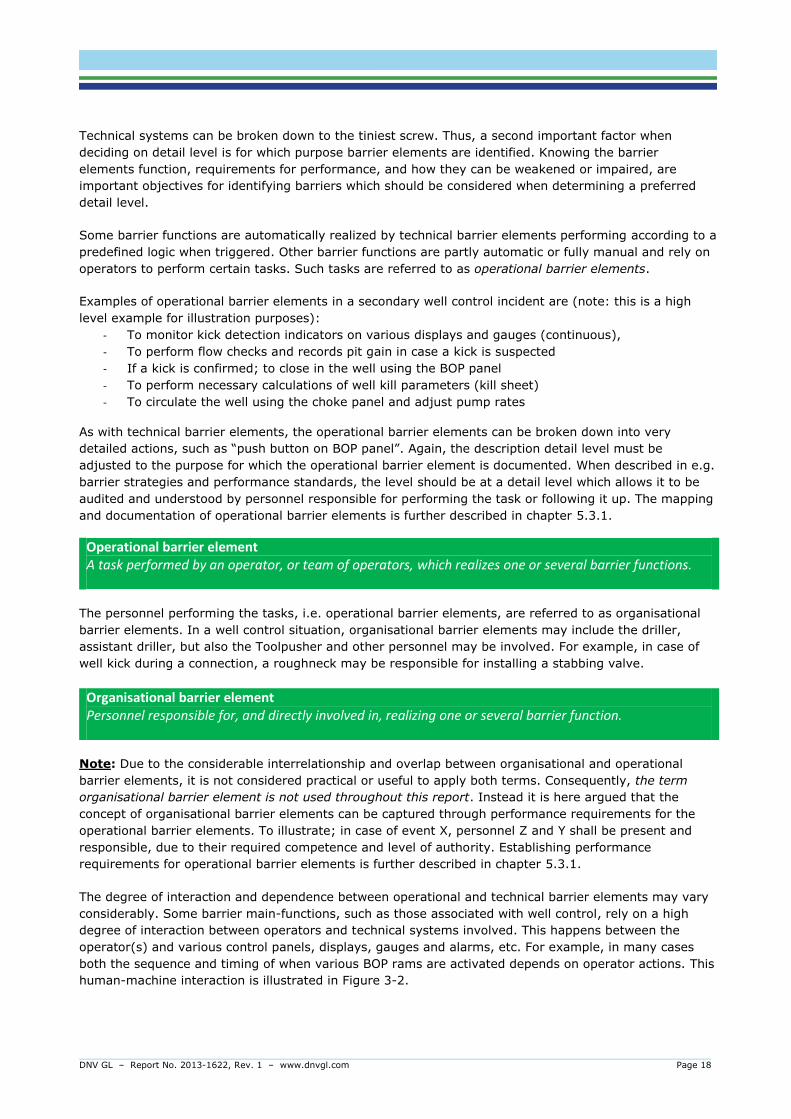
Operational barrier element A task performed by an operator, or team of operators, which realizes one or several barrier functions.
The personnel performing the tasks, i.e. operational barrier elements, are referred to as organisational
barrier elements. In a well control situation, organisational barrier elements may include the driller,
assistant driller, but also the Toolpusher and other personnel may be involved. For example, in case of
well kick during a connection, a roughneck may be responsible for installing a stabbing valve.
Organisational barrier element Personnel responsible for, and directly involved in, realizing one or several barrier function.
Note: Due to the considerable interrelationship and overlap between organisational and operational
barrier elements, it is not considered practical or useful to apply both terms. Consequently, the term
organisational barrier element is not used throughout this report. Instead it is here argued that the
concept of organisational barrier elements can be captured through performance requirements for the
operational barrier elements. To illustrate; in case of event X, personnel Z and Y shall be present and
responsible, due to their required competence and level of authority. Establishing performance
requirements for operational barrier elements is further described in chapter 5.3.1.
The degree of interaction and dependence between operational and technical barrier elements may vary
considerably. Some barrier main-functions, such as those associated with well control, rely on a high
degree of interaction between operators and technical systems involved. This happens between the
operator(s) and various control panels, displays, gauges and alarms, etc. For example, in many cases
both the sequence and timing of when various BOP rams are activated depends on operator actions. This
human-machine interaction is illustrated in Figure 3-2.

DNV GL – Report No. 2013-1622, Rev. 1 – www.dnvgl.com Page 19
Figure 3-2: A barrier function being realized by organisational, operational and technical
barrier elements.
However, it is also important make notice of the various operator tasks (i.e. set of actions) leading up to
the activation of the BOP or adjustment of pump rates and choke valves. These actions are highly
depending on how the kick was detected and diagnosis of situation criticality. This process is not just a
result of interpreting information on displays and monitors, but may also depend on communication
between the Driller, drilling crew, Toolpusher and others.
Task A piece of work (physical action or a cognitive process) that an operator, or team of operators, is
required to do in order to achieve system goals (Kirwan & Ainsworth, 1992).
Comments: In the case of operational barrier elements, the system goal is to realize a barrier main-function.

DNV GL – Report No. 2013-1622, Rev. 1 – www.dnvgl.com Page 20
Figure 3-3 shows a simple, sequential task model of which cognitive and physical actions may comprise
a operational barrier element. The figure also illustrates the influence of performance shaping factors on
task performance. This refers to how procedures, training, workload and other human factors influence
how the task is performed (see chapter 5.3.1 for further explanation).
Figure 3-3: Cognitive and physical actions in an operational barrier element
It is important to note that not all operational barrier elements work in close conjunction with technical
barrier elements to realize barrier functions. Other operational barrier elements, such as some of those
related to emergency preparedness are almost exclusively performed by operating personnel and with
little or no direct use of technical barrier elements (e.g. search and rescue).
Furthermore, operational barrier elements should not be confused with tasks having an indirect influence
on performance of technical barrier elements. This typically includes tasks associated with testing,
inspection and maintenance of barrier elements. While these tasks may be critical to safety and
environment, they are not directly part of realizing barrier functions. For example, in case of drilling into
formations with unexpected (high) formation pore pressure, maintenance on the BOP will not help you to
deal with the situation there and then.
Table 3-2 gives examples of barrier elements based on the definitions in this report.

DNV GL – Report No. 2013-1622, Rev. 1 – www.dnvgl.com Page 21
Table 3-2: Example of barrier elements
Categories Technical barrier elements (active)
Technical barrier elements (passive)
Operational barrier elements
Drilling
Mud pumps, de-gasser, BOP rams and preventers, choke & kill line incl. valves, control
systems etc.
Wellhead, casing and liner, marine riser, drilling fluid (mud), cement, in-situ formation etc.
Monitoring and control of well pressures and volumes, kick detection, operating BOP and
choke/diverter panel etc.
Topside Fire and gas detectors, PA and alarms, ignition
source control etc.
Fire walls, open and closed drains, layout arrangements, piping and flanges etc.
Search & rescue, operating firefighting
equipment, etc.
Maritime Ballasting system, thrusters, position
keeping system etc.
Hull, water tight compartments, anchor
lines etc.
Operate MOB boat,
weather monitoring, emergency and controlled disconnect,
ballasting operations, monitor and notify ships etc.
3.3 Safety system and safety function
PSA requirements refer to safety systems, safety functions, and barriers but without any clear distinction
between what is what. The definitions may also vary somewhat between different standards. Systems
such as those labelled as Fire and Gas, Ignition Source Control, Emergency Power Systems, Active Fire
Protection etc. are often used to categorize safety systems which perform safety functions. These system
names are also commonly used as titles for Performance Standards (see chapter 0) in which
performance requirements for barrier elements are described.
Safety function Physical measures which reduce the probability of a situation of hazard and accident occurring, or which limit the consequences of an accident (NORSOK S-001; NORSOK Z-008).
Safety system System which realises one or more active safety functions (NORSOK Z-008).
As can be read from the definitions, the terms safety system and function overlap with barrier element
and barrier function. In this report, the following logic applies:
- Safety systems can be identified as barrier elements, or contain several barrier elements. This
depends on the level of detail each company chooses to use for defining barrier elements and
their corresponding performance standard structure.
- A safety system is not per definition a barrier element. Barrier elements are identified based on
whether or not they perform a barrier function for preventing major accidents.
- A barrier function represents a type of safety function which purpose is to reduce major accident
risk. Safety functions may also cover measures for reducing occupational accident risk.
Also, the wording used in rules and regulations has implications on the interpretation of safety terms.
Section 5 of PSA Management Regulations specifically refers to the term barrier, and not safety system.
Consequently, safety systems may not fall under the requirements stipulated in Section 5 unless
identified as a barrier.
DNV GL – Report No. 2013-1622, Rev. 1 – www.dnvgl.com Page 22
3.4 Safety critical element
Another common term used by several companies is safety critical element (SCE). The term originates
from the UK Offshore Installations (Safety Case) Regulations 2005. This regulation states that a record
of safety critical elements shall be established for hazards with the potential to cause a major accident.
The party responsible for risk must have a verification scheme covering the identified safety critical
elements on the installation. An independent and competent person must ensure by examination that
the Safety Critical elements are suitable and remain in good repair and that conditions are met.
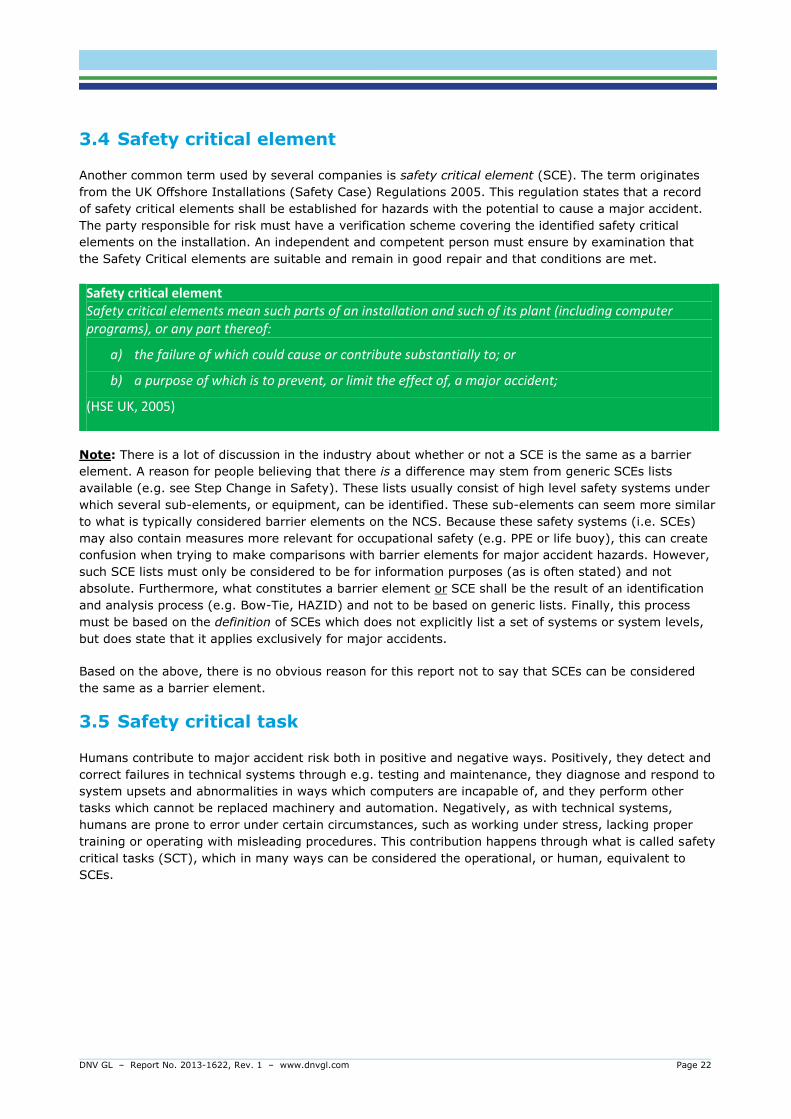
Safety critical element Safety critical elements mean such parts of an installation and such of its plant (including computer programs), or any part thereof:
a) the failure of which could cause or contribute substantially to; or
b) a purpose of which is to prevent, or limit the effect of, a major accident;
(HSE UK, 2005)
Note: There is a lot of discussion in the industry about whether or not a SCE is the same as a barrier
element. A reason for people believing that there is a difference may stem from generic SCEs lists
available (e.g. see Step Change in Safety). These lists usually consist of high level safety systems under
which several sub-elements, or equipment, can be identified. These sub-elements can seem more similar
to what is typically considered barrier elements on the NCS. Because these safety systems (i.e. SCEs)
may also contain measures more relevant for occupational safety (e.g. PPE or life buoy), this can create
confusion when trying to make comparisons with barrier elements for major accident hazards. However,
such SCE lists must only be considered to be for information purposes (as is often stated) and not
absolute. Furthermore, what constitutes a barrier element or SCE shall be the result of an identification
and analysis process (e.g. Bow-Tie, HAZID) and not to be based on generic lists. Finally, this process
must be based on the definition of SCEs which does not explicitly list a set of systems or system levels,
but does state that it applies exclusively for major accidents.
Based on the above, there is no obvious reason for this report not to say that SCEs can be considered
the same as a barrier element.
3.5 Safety critical task
Humans contribute to major accident risk both in positive and negative ways. Positively, they detect and
correct failures in technical systems through e.g. testing and maintenance, they diagnose and respond to
system upsets and abnormalities in ways which computers are incapable of, and they perform other
tasks which cannot be replaced machinery and automation. Negatively, as with technical systems,
humans are prone to error under certain circumstances, such as working under stress, lacking proper
training or operating with misleading procedures. This contribution happens through what is called safety
critical tasks (SCT), which in many ways can be considered the operational, or human, equivalent to
SCEs.
DNV GL – Report No. 2013-1622, Rev. 1 – www.dnvgl.com Page 23
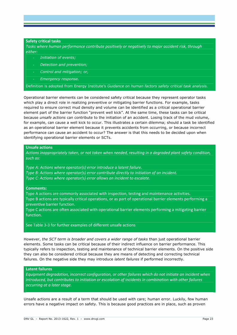
Safety critical tasks Tasks where human performance contribute positively or negatively to major accident risk, through either:
- Initiation of events;
- Detection and prevention;
- Control and mitigation; or,
- Emergency response.
Definition is adopted from Energy Institute’s Guidance on human factors safety critical task analysis.
Operational barrier elements can be considered safety critical because they represent operator tasks
which play a direct role in realizing preventive or mitigating barrier functions. For example, tasks
required to ensure correct mud density and volume can be identified as a critical operational barrier
element part of the barrier function “prevent well kick”. At the same time, these tasks can be critical
because unsafe actions can contribute to the initiation of an accident. Losing track of the mud volume,
for example, can cause a well kick to occur. This illustrates a certain dilemma; should a task be identified
as an operational barrier element because it prevents accidents from occurring, or because incorrect
performance can cause an accident to occur? The answer is that this needs to be decided upon when
identifying operational barrier elements or SCTs.
Unsafe actions
Actions inappropriately taken, or not taken when needed, resulting in a degraded plant safety condition, such as:
Type A: Actions where operator(s) error introduce a latent failure. Type B: Actions where operator(s) error contribute directly to initiation of an incident. Type C: Actions where operator(s) error allows an incident to escalate.
Comments: Type A actions are commonly associated with inspection, testing and maintenance activities. Type B actions are typically critical operations, or as part of operational barrier elements performing a preventive barrier function. Type C actions are often associated with operational barrier elements performing a mitigating barrier function.
See Table 3-3 for further examples of different unsafe actions
However, the SCT term is broader and covers a wider range of tasks than just operational barrier
elements. Some tasks can be critical because of their indirect influence on barrier performance. This
typically refers to inspection, testing and maintenance of technical barrier elements. On the positive side
they can also be considered critical because they are means of detecting and correcting technical
failures. On the negative side they may introduce latent failures if performed incorrectly.
Latent failures Equipment degradation, incorrect configuration, or other failures which do not initiate an incident when introduced, but contributes to initiation or escalation of incidents in combination with other failures occurring at a later stage.
Unsafe actions are a result of a term that should be used with care; human error. Luckily, few human
errors have a negative impact on safety. This is because good practices are in place, such as proven

DNV GL – Report No. 2013-1622, Rev. 1 – www.dnvgl.com Page 24
procedures and good training. However, in those cases unsafe actions may result in critical outcomes,
human error should be managed systematically. Well control and emergency preparedness are good
examples.
Human error Out-of-tolerance actions, or deviations from the norm, where the limits of acceptable performance are defined by the system.
Note: As a general rule, personnel shall not be subject to sanctions for committing errors. Humans
correct more errors than they cause, for example by working around poor or incorrect procedures, or
making faulty technology work. When humans err, it is more likely a result error producing conditions
than deliberate violations. Only when an operator or team of operators has repeatedly committed errors,
despite prior warnings, sanctions can be considered. If violations are a result of company culture, such
as pressure to continue production, sanctions should not be applied. While the human condition cannot
be changed, but we can change the conditions under which humans work. This should be the principle
both for prevention and explanation of human error.
Table 3-3: Examples of unsafe actions
Unsafe actions Examples
Type A: Actions where operator(s)
error introduce a latent condition.
- Wrong line-up of valves and piping arrangement, for example after maintenance or testing → at a later stage, this may cause
unexpected pressure build ups, leaks, or unavailability of equipment. This may especially occur if pressure levels or flow rates/routes change a later time.
- Incorrect calibration or testing of gas detectors, such as cleaning the detector lens before performing the test → in case of a gas
leak, this may cause detectors not working as expected when needed. The detector may not detect intended gas levels if the
lens is dirty.
- Applying wrong rating levels when pressure testing the BOP, or testing pressure levels in the wrong order → may cause damage
to critical components, or the test results may not reflect expected pressure levels in the well. In case of a kick or blowout, the BOP may malfunction or not perform as expected.
Type B: Actions where operator(s)
error contribute directly to initiation of an incident.
- Connecting wrong mud pit (e.g. premix) to the active system resulting in circulation of mud with too low density, combined with infrequent, incorrect or omitted mud weight controls → if circulated too long, and if mud s.g. is already close to the pore pressure, this may cause unintentional flow from formations to wellbore.
- Exceeding lifting capacities or maloperation of crane and lifting
equipment → may cause dropped or swinging object onto critical
equipment, such as well testing equipment, well template or subsea pipelines.
Type C: Actions where operator(s) error allows an incident to escalate.
- Shutting in the well too late → If the well is shut in too late, this
may contribute to escalation of a well kick, potentially resulting in a blowout. For example, gas may have reached the riser (if the BOP is subsea) and have to be diverted. The pressure build up may become higher than annular preventer is capable of handling, causing erosion and flow paths for the kick.

DNV GL – Report No. 2013-1622, Rev. 1 – www.dnvgl.com Page 25
Unsafe actions Examples
- Incorrect spacing out of the drill string, or activating BOP rams in wrong order in case of a well kick →may allow flow paths for the kick and hydrocarbons entering the riser. High pressure and flow
levels may in turn cause erosion and weakening of BOP functions. - Omitting to disconnect rig from the well in case of e.g. extreme
weather → may cause loss of well integrity (e.g. damage to well head and BOP) and in worst case a well control incident. In case of a blowout, omitting to disconnect will expose the rig to hazards (e.g. hydrocarbons) and allow incident escalation.
3.6 Performance shaping factors
Operator task performance, such as in operational barrier elements, is influenced by what is called
performance shaping factors (PSFs). This refers to human factors, such as mental and physical
capabilities, but also contextual (e.g. workplace) factors in which the operator is situated. Imagine the
case of a well control situation. The driller, drill crew, toolpusher and company man all rely heavily on
their competence and experience, procedures (e.g. Driller’s Method), and human-machine interface
(HMI) to successfully handle the situation. Social factors also come into play, such as norms concerning
work practice, teamwork and leadership. The influence of PSFs on task performance is illustrated in
Figure 3-2 and Figure 3-3.
Performance shaping factors Human, workplace or other contextual factors which have a significant effect on an operator’s or crew of operator’s performance. Comments: The term performance shaping factors is also sometimes used about factors which in general have an indirect influence barrier performance, thus including e.g. weather, maintenance, barrier degradation mechanisms, and more. This makes it an “everything and nothing” kind of term, with little added
explanatory value. Consequently, in this report, performance shaping factors is exclusively used about factors with significant influence on human performance.
4 BARRIER MANAGEMENT FRAMEWORK
To be able to manage barriers a framework needs to be established, integrated and operationalized in
the management system within the rig organisation. Necessary processes and systems to fulfil the
framework need to be identified, with relevant information needs, owners and responsibilities. Existing
processes, systems and tools for HSE and risk management like QRA, ALARP, SJA, toolbox talk,
reporting, communication and training will also have relevance for barrier management. To be able to
support the barrier management perspective, some existing documentation or processes structure may
have to be adjusted to suite also this prospective.
The framework is divided into:
- Establish and implement barrier management
- Barrier management in operation
- Monitoring barrier performance
- Operational risk management

DNV GL – Report No. 2013-1622, Rev. 1 – www.dnvgl.com Page 26
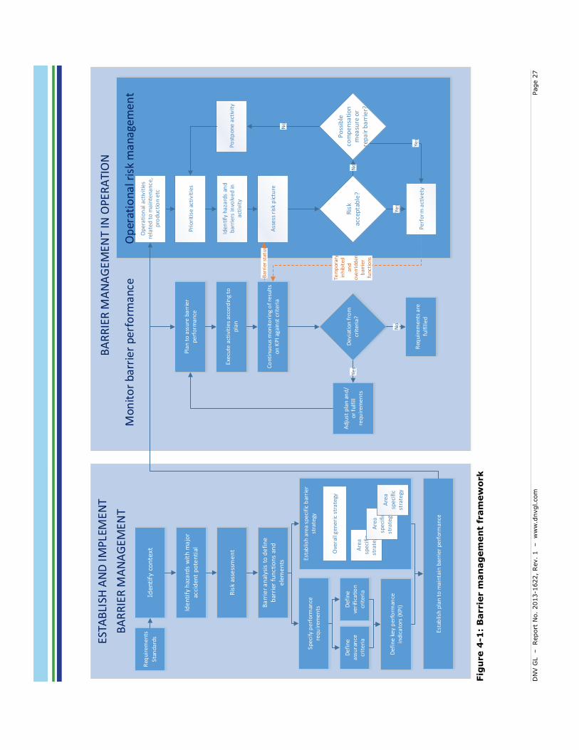
“Establish and implement barrier management” includes identification of barrier elements with
description of roles and performance requirements. The barriers should be identifiable; both in the
technical hierarchy and in procedures. Program to prevent degradation of barriers needs to be
established and implemented. Activities to assure and verify barrier performance needs to be
implemented to be able to monitor barrier performance.
“Barrier management in operation” includes a process for monitoring barrier performance and a process
for managing risk in operation. Objective of the barrier monitoring activity is to provide decision support
for different management levels in the organisation. Risk management in operation can be achieved by
considering both activity level and barrier status prior to each (set) of operations to be performed.
Elements to consider in a barrier management framework is visualised in Figure 4-1 and each element is
described in Table 4-1.
DN
V G
L
– Report
No.
2013-1
622,
Rev.
1 – w
ww
.dnvgl.com
Page 2
7
Fig
ure 4
-1:
Barrie
r m
an
ag
em
en
t fr
am
ew
ork
Esta
blis
h pl
an t
o m
aint
ain
barr
ier
perf
orm
ance
Esta
blis
h ar
ea s
peci
fic b
arri
er
stra
tegy
De
fin
e k
ey
pe
rfo
rman
ce
indi
cato
rs (
KP
I)
Plan
to
assu
re b
arri
er
per
form
ance
Exec
ute
acti
viti
es a
ccor
din
g to
p
lan
Co
nti
nu
ou
s m
on
ito
rin
g o
f res
ult
s o
n K
PI a
gain
st c
rite
ria
Dev
iati
on
fro
m
crit
eria
?
Req
uire
men
ts a
re
fulfi
lled
Ad
just
pla
n a
nd
/or
fulf
ill
req
uir
emen
tsYe
s
No
Ide
ntif
y h
aza
rds
and
b
arri
ers
invo
lved
in
acti
vity
Per
form
act
ivet
y
Post
pon
e ac
tivit
y
Ass
ess
risk
pic
ture
Def
ine
assu
ran
ce
crit
eria
Def
ine
veri
fica
tio
n
crit
eria
Ide
nti
fy h
aza
rds
wit
h m
ajo
r ac
cid
ent
po
ten
tial
Ris
k as
sess
me
nt
Ba
rrie
r a
nal
ysis
to
de
fin
e
bar
rier
fu
nct
ion
s an
d
ele
me
nts
Spec
ify p
erfo
rman
ce
requ
irem
ents
No
No
Yes
Yes
Bar
rier
sta
tus
Tem
por
ary
inh
ibit
ed
and
ove
rrid
den
b
arri
er
func
tio
ns
Pri
ori
tise
act
ivit
ies
ESTA
BLI
SH A
ND
IMPL
EMEN
T
BA
RR
IER
MA
NA
GEM
ENT
BA
RR
IER
MA
NA
GEM
ENT
IN O
PER
ATI
ON
Identify
conte
xt
Op
erat
ion
al a
ctiv
itie
s re
late
d t
o m
ain
ten
ance
, pr
odu
ctio
n et
c
Ove
rall
gen
eric
str
ateg
y
Are
a
spec
ific
stra
tegy
Are
a sp
ecifi
c st
rate
gyA
rea
spec
ific
stra
tegy
Req
uir
emen
ts
Stan
dar
ds
Op
erat
iona
l ris
k m
anag
emen
tM
onit
or
barr
ier
perf
orm
ance

DN
V G
L
– Report
No.
2013-1
622,
Rev.
1 – w
ww
.dnvgl.com
Page 2
8
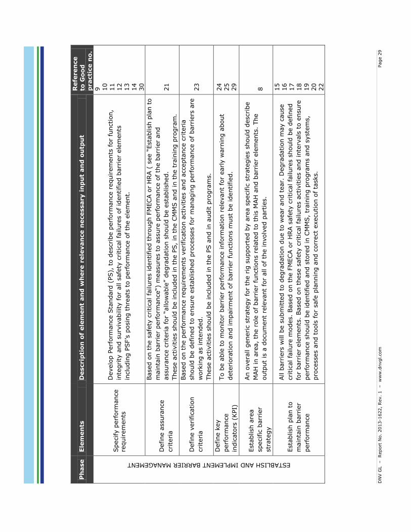
Tab
le 4
-1:
Descrip
tion
of
ele
men
ts t
o c
on
sid
er i
n a
barrie
r m
an
ag
em
en
t fr
am
ew
ork
Ph
ase
Ele
men
ts
Descrip
tio
n o
f ele
men
t an
d w
here r
ele
van
ce n
ecessary i
np
ut
an
d o
utp
ut
Refe
ren
ce
to G
oo
d
practi
ce n
o.
ESTABLISH AND IMPLEMENT BARRIER MANAGEMENT
Identify
conte
xt
The r
ig s
hould
be d
escribed w
ith a
ssocia
ted r
egula
tory
regim
e,
boundari
es a
nd lim
itations
for
opera
tion.
Input
to t
his
ele
ment
will be r
ule
s/s
tandard
s/c
lass r
equir
em
ents
that
the u
nit is d
esig
ned
for.
Based o
n r
equir
em
ents
pre
scriptive b
arr
ier
ele
ments
with p
erf
orm
ance r
equir
em
ent
should
be identified a
s a
n o
utp
ut.
(e.g
. all a
ir inle
ts s
hall b
e e
quip
ped w
ith 3
gas d
ete
cto
rs,
dete
cting 2
0%
LEL,
rais
ing a
larm
no late
r th
an 5
seconds a
fter
exposure
to g
as c
oncentr
ations a
bove 2
0%
LEL).
1
Identify
hazard
s w
ith
majo
r accid
ent
pote
ntial
Use “
HAZID
(fr
om
ris
k a
ssessm
ent)
” to
identify
hazard
s a
nd e
valu
ate
if each h
azard
can
realize h
azard
ous e
vents
with a
majo
r accid
ent
pote
ntial (M
AH
). T
he H
AZID
should
als
o
identify
exis
ting a
nd a
ny r
equir
ed a
dditio
nal re
quir
em
ents
to c
ontr
ol th
e M
AH
pic
ture
in
question.
It is r
ecom
mended t
hat
this
evalu
ation is d
one p
er
are
a.
Outp
ut
will be a
lis
t of M
AH
per
are
a a
nd a
rgum
ent
for
hazard
s t
hat
are
not
inclu
ded.
This
list
should
be inclu
ded in t
he b
arr
ier
str
ate
gy.
3
Ris
k a
ssessm
ent
The r
isk a
ssessm
ent
is t
o e
valu
ate
and identify
if additio
nal contr
ols
are
required t
o p
revent
or
mitig
ate
the a
ctu
al accid
enta
l lo
ads.
The r
isk a
ssessm
ent
will als
o q
uantify
functional
requir
em
ents
to t
he b
arr
ier
ele
ments
.
(e.g
. “a
rea c
overa
ge”
for
gas d
ete
ction in a
n a
rea –
well t
est
are
a –
could
be a
t le
ast
5
dete
cto
rs in o
pera
tion t
o o
bta
in s
uffic
ient
“sensitiv
ity”
or
“dete
ction p
robability”
for
the
are
a.)
2
Barr
ier
analy
sis
to
define b
arr
ier
functions a
nd
ele
ments
For
each M
AH
within
each a
rea identified in t
he H
AZID
, barr
ier
functions t
o p
revent
and
mitig
ate
the M
AH
should
be f
urt
her
deta
iled.
For
each f
unction b
arr
ier
ele
ments
as c
ontr
ols
should
be inclu
ded.
It is r
ecom
mended t
hat
this
ste
p a
ligns d
efinitio
ns a
nd t
erm
s a
s far
as
possib
le t
o t
he t
echnic
al hie
rarc
hy in t
he m
ain
tenance s
yste
m t
o a
llow
for
synerg
ies in
feedback r
eport
ing fro
m t
esting &
repair
s e
tc.
Outp
ut
from
this
ele
ment
can b
e b
arr
ier
dia
gra
ms (
e.g
. Bow
-Tie
) and b
arr
ier
matr
ices o
r
table
s a
nd s
hould
be inclu
ded in t
he b
arr
ier
str
ate
gy.
4
5
6
7
DN
V G
L
– Report
No.
2013-1
622,
Rev.
1 – w
ww
.dnvgl.com
Page 2
9
Ph
ase
Ele
men
ts
Descrip
tio
n o
f ele
men
t an
d w
here r
ele
van
ce n
ecessary i
np
ut
an
d o
utp
ut
Refe
ren
ce
to G
oo
d
practi
ce n
o.
ESTABLISH AND IMPLEMENT BARRIER MANAGEMENT
Specify p
erf
orm
ance
requir
em
ents
Develo
p P
erf
orm
ance S
tandard
(PS),
to d
escribe p
erf
orm
ance r
equir
em
ents
for
function,
inte
grity
and s
urv
ivability f
or
all s
afe
ty c
ritical fa
ilure
s o
f id
entified b
arr
ier
ele
ments
inclu
din
g P
SF’s
posin
g t
hre
ats
to p
erf
orm
ance o
f th
e e
lem
ent.
9
10
11
12
13
14
30
Define a
ssura
nce
cri
teria
Based o
n t
he s
afe
ty c
ritical fa
ilure
s identified t
hro
ugh F
MEC
A o
r H
RA (
see “
Esta
blish p
lan t
o
main
tain
barr
ier
perf
orm
ance“)
measure
s t
o a
ssure
perf
orm
ance o
f th
e b
arr
ier
and
assura
nce c
rite
ria for
“allow
able
” degra
dation s
hould
be e
sta
blished.
These a
ctivitie
s s
hould
be inclu
ded in t
he P
S,
in t
he C
MM
S a
nd in t
he t
rain
ing p
rogra
m.
21
Define v
eri
fication
cri
teria
Based o
n t
he p
erf
orm
ance r
equir
em
ents
veri
fication a
ctivitie
s a
nd a
ccepta
nce c
rite
ria
should
be d
efined t
o e
nsure
esta
blished p
rocesses for
managin
g p
erf
orm
ance o
f barr
iers
are
work
ing a
s inte
nded.
These a
ctivitie
s s
hould
be inclu
ded in t
he P
S a
nd in a
udit p
rogra
ms.
23
Define k
ey
perf
orm
ance
indic
ato
rs (
KPI)
To b
e a
ble
to m
onitor
barr
ier
perf
orm
ance info
rmation r
ele
vant
for
earl
y w
arn
ing a
bout
dete
riora
tion a
nd im
pair
ment
of barr
ier
functions m
ust
be identified.
24
25
29
Esta
blish a
rea
specific
barr
ier
str
ate
gy
An o
vera
ll g
eneri
c s
trate
gy for
the r
ig s
upport
ed b
y a
rea s
pecific
str
ate
gie
s s
hould
describe
MAH
in a
rea,
the r
ole
of barr
ier
functions r
ela
ted t
o t
his
MAH
and b
arr
ier
ele
ments
. The
outp
ut
is a
docum
ent
rele
vant
for
all o
f th
e involv
ed p
art
ies.
8
Esta
blish p
lan t
o
main
tain
barr
ier
perf
orm
ance
All b
arr
iers
will be s
ubm
itte
d t
o d
egra
dation d
ue t
o w
ear
and t
ear.
Degra
dation m
ay c
ause
cri
tical fa
ilure
modes.
Based o
n t
he F
MECA o
r H
RA s
afe
ty c
ritical fa
ilure
s s
hould
be d
efined
for
barr
ier
ele
ments
. Based o
n t
hese s
afe
ty c
ritical fa
ilure
s a
ctivitie
s a
nd inte
rvals
to e
nsure
perf
orm
ance s
hould
be identified a
nd s
tore
d in C
MM
S,
train
ing p
rogra
ms a
nd s
yste
ms,
pro
cesses a
nd t
ools
for
safe
pla
nnin
g a
nd c
orr
ect
execution o
f ta
sks.
15
16
17
18
19
20
22

DN
V G
L
– Report
No.
2013-1
622,
Rev.
1 – w
ww
.dnvgl.com
Page 3
0
Ph
ase
Ele
men
ts
Descrip
tio
n o
f ele
men
t an
d w
here r
ele
van
ce n
ecessary i
np
ut
an
d o
utp
ut
Refe
ren
ce
to G
oo
d
practi
ce n
o.
MONITOR BARRIER PERFORMANCE
Pla
n t
o m
onitor
barr
ier
perf
orm
ance
The a
ssura
nce a
nd v
eri
fication a
ctivitie
s s
chedule
d m
ake a
pla
n for
monitori
ng b
arr
ier
perf
orm
ance.
27
28
31
Execute
assura
nce a
nd
veri
fication a
ctivitie
s
accord
ing t
o p
lan
It is im
port
ant
that
the a
ssura
nce a
ctivitie
s a
re p
erf
orm
ed a
ccord
ing t
o t
est
pro
cedure
s a
nd r
eport
ed c
orr
ectly.
26
Continuous m
onitori
ng o
f
results o
n K
PI
again
st
cri
teria
Based o
n t
he t
est
results a
nd info
rmation r
ele
vant
for
earl
y w
arn
ing o
f dete
riora
tion o
f
barr
iers
KPI
should
be m
onitore
d a
nd e
valu
ate
d a
gain
st
esta
blished c
rite
ria.
Devia
tion fro
m c
rite
ria?
Based o
n e
valu
ation o
f th
e b
arr
ier
sta
tus r
ela
ted r
isk s
hould
be a
ssessed a
nd
com
munic
ate
d.
Requir
em
ents
are
fulfille
d
Barr
ier
sta
tus is a
ccord
ance t
o t
he p
erf
orm
ance r
equirem
ents
.
Adju
st
pla
n a
nd/o
r fu
lfil
requir
em
ents
The p
erf
orm
ance r
equir
em
ents
are
not
met.
The p
lan for
ensure
perf
orm
ance o
f
barr
iers
should
be a
dju
ste
d b
y intr
oducin
g m
ore
effic
ient
activitie
s o
r changin
g t
he
inte
rval
OPERATIONAL RISK MANAGEMENT
Opera
tional activitie
s
rela
ted t
o m
ain
tenance,
pro
duction e
tc.
Based o
n input
from
diffe
rent
pro
cesses a
s d
rillin
g,
main
tenance,
managem
ent
of
change e
tc.
activitie
s t
o facilitate
safe
and e
ffic
ient
opera
tion w
ill be p
roposed.
Prioritise a
ctivitie
s
Diffe
rent
levels
of pla
nnin
g w
ill to
a c
ert
ain
exte
nt
evalu
ate
, pri
oritise a
nd c
oord
inate
activitie
s b
ut
at
the s
harp
end t
he W
ork
Perm
it p
rocess a
nd t
he e
venin
g m
eeting
needs t
o r
isk a
ssess a
nd p
rioritise a
mong p
roposed a
ctivitie
s t
o b
e p
erf
orm
ed t
he n
ext
day.
These a
ctivitie
s c
an b
e g
rouped in:
Activitie
s t
hat
requir
e W
P,
norm
al ro
utine
work
. M
ost
rig c
om
panie
s h
ave e
sta
blished s
yste
ms,
pro
cesses a
nd t
ools
for
managin
g
risk in t
hese a
ctivitie
s.
Identify
hazard
s a
nd
barr
iers
involv
ed in
activity
This
ele
ment
inclu
des a
n identification o
f hazard
s t
he a
ctivity m
ay c
ause a
nd r
ele
vant
requir
em
ents
for
the a
ctivity t
o b
e p
erf
orm
ed.
Technic
al and o
pera
tional barr
iers
to
pre
vent
and c
ontr
ol th
ese h
azard
s n
eed t
o b
e identified.
Com
pete
nce o
n r
isk a
nd
technic
al safe
ty a
re v
ital to
perf
orm
this
ele
ment.

DN
V G
L
– Report
No.
2013-1
622,
Rev.
1 – w
ww
.dnvgl.com
Page 3
1
Ph
ase
Ele
men
ts
Descrip
tio
n o
f ele
men
t an
d w
here r
ele
van
ce n
ecessary i
np
ut
an
d o
utp
ut
Refe
ren
ce
to G
oo
d
practi
ce n
o.
Assess r
isk p
ictu
re
With k
now
ledge o
f barr
ier
sta
tus t
he r
isk p
ictu
re in t
he a
ctivity a
nd o
vera
ll o
n t
he r
ig
must
be a
ssessed.
Ris
k a
ccepta
ble
?
This
ele
ment
inclu
des a
n e
valu
ation o
f th
e r
isk p
ictu
re in t
he a
ctivity its
elf a
nd b
ased
on t
he r
isk p
ictu
re o
n a
n o
vera
ll r
ig level. I
f all identified r
equir
em
ents
are
met
the
risk is a
ccepta
ble
.
Possib
le c
om
pensation
measure
or
repair
barr
ier?
If r
isk p
ictu
re in t
he a
ctivity is n
ot
accepta
ble
due t
o r
equir
em
ents
not
met
or
impair
ed
barr
iers
a s
olu
tion c
an b
e t
o intr
oduce c
om
pensating m
easure
s o
r fixin
g b
arr
iers
. If
com
pensation m
easure
s intr
oduced a
re long t
erm
/perm
anent
the P
erf
orm
ance
requir
em
ents
in P
S s
hould
inclu
de t
his
info
rmation.
Postp
one a
ctivity
If r
isk level in
activity is n
ot
accepta
ble
the a
ctivity s
hould
postp
oned a
nd e
valu
ate
d
for
re-p
lannin
g if still r
ele
vance for
safe
and e
ffic
ient
opera
tion.
Perf
orm
activity
If r
isk level is
accepta
ble
and r
equir
em
ents
are
met
the a
ctivity c
an b
e p
erf
orm
ed.
DNV GL – Report No. 2013-1622, Rev. 1 – www.dnvgl.com Page 32
5 ESTABLISH AND IMPLEMENT BARRIER MANAGEMENT
A pre-requisite for successful barrier management in operations is that the principles of barrier
management are implemented as part of the rigs design and management system. Although it is
outside scope of this document to describe barrier management in the design phase of a rig, it is still
necessary to revisit some key topics. For rigs in operations, some preparations normally made in the
design phase have to be considered. This especially concerns documentation of rationale behind why
the barriers have been implemented in the first place, and what their requirements for performance
are.
This chapter explains the purpose and scope of documentation which is essential when it comes to
forming the basis for barrier management, namely:
- Barrier analysis (Bow-Tie’s and barrier matrices/tables)
- Performance requirements documented in performance standards
- Area specific barrier strategies
For more details on implementation of barrier management in design, see PSA’s document titled
“Principles for barrier management in the petroleum industry” (PSA, 2013).
5.1 Barrier analysis
Section 5 of PSA’s Management Regulations stipultates that personnel shall be aware of what barriers
have been establihsed, their functions, and performance requirements.
Management regulations, section 5 “Personnel shall be aware of what barriers have been established and which function they are intended to fulfil, as well as what performance requirements have been defined in respect of the technical, operational or organizational elements necessary for the individual barrier to be effective.”
In order to understand and be aware of the rig’s barrier elements and their functions, a systematic
approach is recommended to capture and structure the complexity of barriers. To manage the rig’s
barriers you must first know what they are and what they do. This is the main objective of a barrier
analysis. By tying everything together it allows a systematic approach to management of barriers. The
main purpose is to “paint the complete picture” for a given area where hazards and hazardous events
are linked to corresponding preventive and mitigating barrier functions, barrier element, their role and
performance requirement for each element and function. Once this picture is established it can be used
in planing in operations to identify or highligt barrier elements in “active service” and can assist in
identifying the status of the speciffic elemets to consider for the speciffic task. The result from a barrier
analysis will also be a startingpoint for identifying performance requirements. See example Table 5-1
and Table 5-2.

DNV GL – Report No. 2013-1622, Rev. 1 – www.dnvgl.com Page 33
Good practice 5 Perform a barrier analysis, covering each installation areas, with the following objectives:
- Identify major accident scenarios, incl. hazards, hazardous events and consequences (e.g. through a HAZID)
- Identify barrier main-functions necessary to prevent hazardous events and control/mitigate their consequences
- Identify barrier elements responsible for realizing the barrier main-functions
- Describe the role of each barrier element, explaining how it contributes to the barrier main-function
- Describe the interactions and interfaces between the different barrier elements
Comments: There is no standard approach to barrier analysis, but a combination of barrier diagrams (e.g. Bow-Tie) and barrier matrices or tables are commonly used.
The barrier analysis should be based on a risk or accident model illustrating how the barriers
contribute to risk reduction (i.e. either as preventive or mitigating). For identification of major accident
scenarios, review existing HAZID from QRA or Safety Case, and identify hazardous events within each
area for which barrier functions and barrier elements will be identified. Hazards and hazardous events
which do not have the potential to escalate into major accidents can be excluded from further
evaluations.
The results can be structured and visulized differently dependant of the end use. E.g Table format of
the results is found a effective tool to assist in develop/verify performancew standards and to assist in
developing PM programme to identify assurance activities. Other use commonly use of Barrier
diagrams such as Bow-Tie’s or Swiss Cheese are for visualizing results for communication purposes.
Several different software solutions are available for making Bow-Tie or other types of barrier
diagrams. Most tools allow for visualizing barrier main-functions and barrier elements responsible for
realizing the function. The diagram set-up is ultimately a matter of company preferences, e.g.
depending on how barriers are defined and for what purpose the Bow-Tie is developed. However, a few
“rule of thumbs” exist:
- Avoid complex and detailed Bow-Tie’s, or alternatively enable Bow-Tie’s to be presented with
different levels of detail. Overly complex Bow-Tie’s can become follow and understand and
personnel can be discouraged to use them.
- Avoid confusing measures implemented to avoid barrier degradation (e.g. corrosion
monitoring) with actual barriers implemented with a specific purpose of preventing or
mitigating hazardous events (e.g. containment).
- For identifying barriers, include barrier functions which has a significant effect on the Bow-Tie
event sequence. This means that barrier sub-functions such as “gas detection”, or barrier
elements such as “gas detector”, should not be included as a single barrier in the Bow-Tie
diagram. If single barrier elements are included in the Bow-Tie’s event sequence, this may:
- give a false or incorrect impression of how well safeguarded the system is,
- create a confusing sequence of the barriers in terms of when they are required or
activated throughout the accident event chain,
- will not describe the purpose, i.e. function, of the barrier elements
- Many of the Bow-Ties will have similar consequences. This is particularly relevant for “loss of
life”. Barrier functions to ensure safe rescue, emergency and evaluation will most likely be the
same for many of the hazardous events. In this case a Bow-Tie for “safe evacuation” can be
made instead of repeating same barriers in every Bow-Tie.
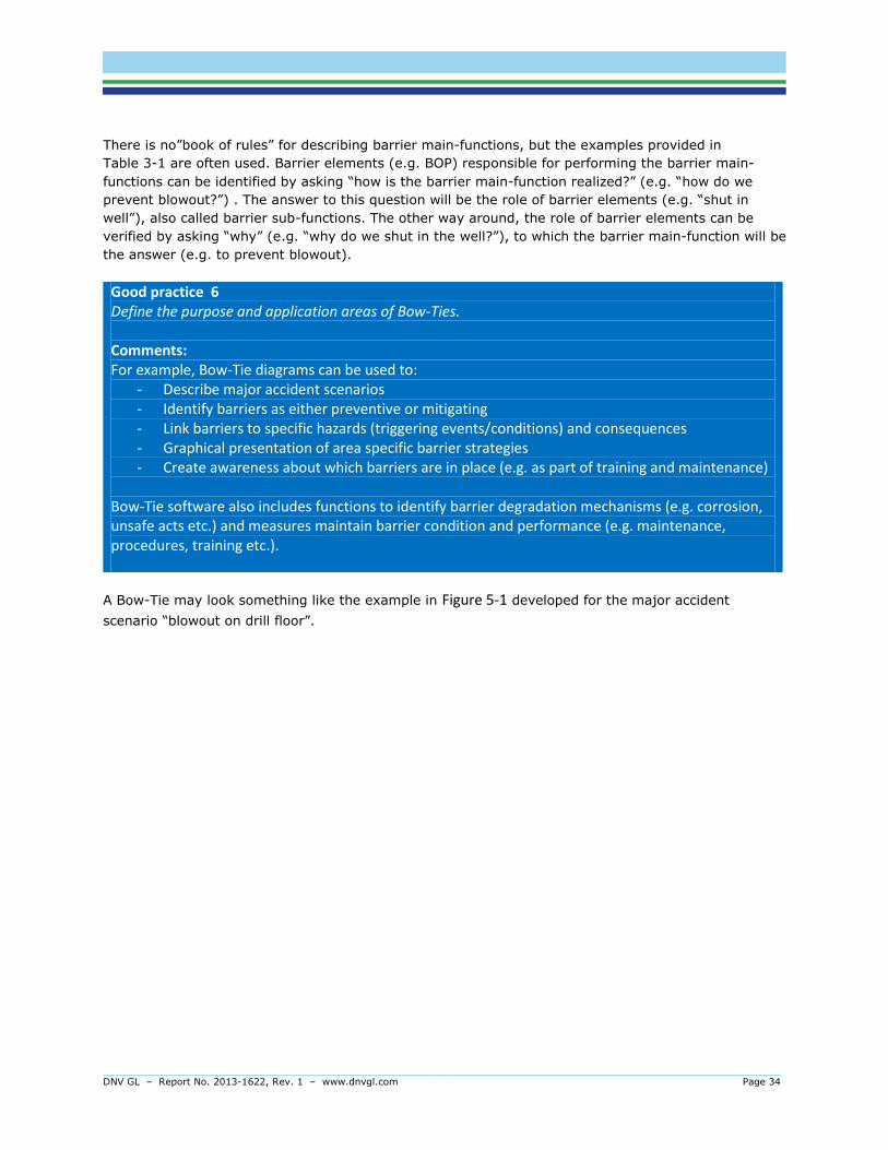
DNV GL – Report No. 2013-1622, Rev. 1 – www.dnvgl.com Page 34
There is no”book of rules” for describing barrier main-functions, but the examples provided in
Table 3-1 are often used. Barrier elements (e.g. BOP) responsible for performing the barrier main-
functions can be identified by asking “how is the barrier main-function realized?” (e.g. “how do we
prevent blowout?”) . The answer to this question will be the role of barrier elements (e.g. “shut in
well”), also called barrier sub-functions. The other way around, the role of barrier elements can be
verified by asking “why” (e.g. “why do we shut in the well?”), to which the barrier main-function will be
the answer (e.g. to prevent blowout).
Good practice 6 Define the purpose and application areas of Bow-Ties. Comments: For example, Bow-Tie diagrams can be used to:
- Describe major accident scenarios - Identify barriers as either preventive or mitigating - Link barriers to specific hazards (triggering events/conditions) and consequences - Graphical presentation of area specific barrier strategies - Create awareness about which barriers are in place (e.g. as part of training and maintenance)
Bow-Tie software also includes functions to identify barrier degradation mechanisms (e.g. corrosion, unsafe acts etc.) and measures maintain barrier condition and performance (e.g. maintenance, procedures, training etc.).
A Bow-Tie may look something like the example in Figure 5-1 developed for the major accident
scenario “blowout on drill floor”.
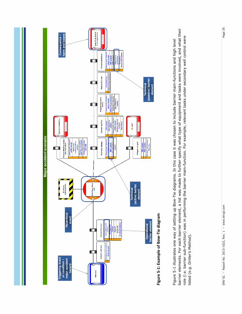
DN
V G
L
– Report
No.
2013-1
622,
Rev.
1 – w
ww
.dnvgl.com
Page 3
5
Fi
gure
5-1
: Exa
mp
le o
f B
ow
-Tie
dia
gram
Fig
ure
5-1
illustr
ate
s o
ne w
ay o
f sett
ing u
p B
ow
-Tie
dia
gra
ms.
In t
his
case it
was c
hosen t
o inclu
de b
arr
ier
main
-functions a
nd h
igh level
barr
ier
ele
ments
. For
each b
arr
ier
ele
ment,
a lis
t w
as m
ade t
o f
urt
her
specify w
hat
type o
f equip
ment
and t
asks w
ere
involv
ed,
and w
hat
their
role
(i.e.
barr
ier
sub-f
unction)
was in p
erf
orm
ing t
he b
arr
ier
main
-function.
For
exam
ple
, re
levant
tasks u
nder
secondary
well c
ontr
ol w
ere
liste
d (
e.g
. D
riller’s M
eth
od).
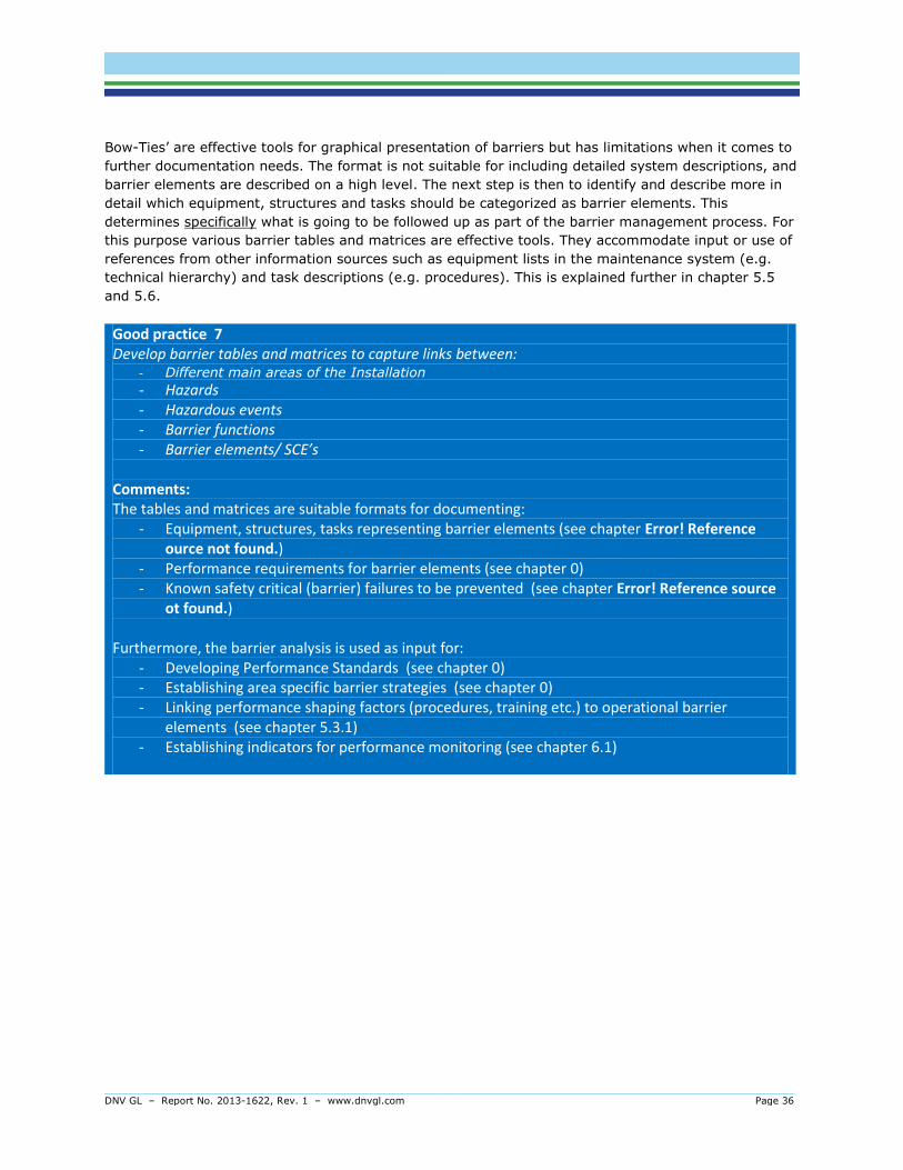
DNV GL – Report No. 2013-1622, Rev. 1 – www.dnvgl.com Page 36
Bow-Ties’ are effective tools for graphical presentation of barriers but has limitations when it comes to
further documentation needs. The format is not suitable for including detailed system descriptions, and
barrier elements are described on a high level. The next step is then to identify and describe more in
detail which equipment, structures and tasks should be categorized as barrier elements. This
determines specifically what is going to be followed up as part of the barrier management process. For
this purpose various barrier tables and matrices are effective tools. They accommodate input or use of
references from other information sources such as equipment lists in the maintenance system (e.g.
technical hierarchy) and task descriptions (e.g. procedures). This is explained further in chapter 5.5
and 5.6.
Good practice 7 Develop barrier tables and matrices to capture links between:
- Different main areas of the Installation
- Hazards - Hazardous events - Barrier functions - Barrier elements/ SCE’s
Comments: The tables and matrices are suitable formats for documenting:
- Equipment, structures, tasks representing barrier elements (see chapter Error! Reference ource not found.)
- Performance requirements for barrier elements (see chapter 0) - Known safety critical (barrier) failures to be prevented (see chapter Error! Reference source
ot found.) Furthermore, the barrier analysis is used as input for:
- Developing Performance Standards (see chapter 0) - Establishing area specific barrier strategies (see chapter 0) - Linking performance shaping factors (procedures, training etc.) to operational barrier
elements (see chapter 5.3.1) - Establishing indicators for performance monitoring (see chapter 6.1)

DNV GL – Report No. 2013-1622, Rev. 1 – www.dnvgl.com Page 37
5.2 Barrier strategy
Management regulation, Section 5 “The operator or the party responsible for operation of an offshore or onshore facility, shall stipulate the strategies and principles that form the basis for design, use and maintenance of barriers, so that the barriers' function is safeguarded throughout the offshore or onshore facility's life.”
In order to fulfil this requirement a strategy document is commonly established, although it is not
strictly required to have gathered all this information in one document. The document is normally
referred to as the Safety Strategy or Barrier Strategy and it is stated that it should be area specific.
Barrier Strategy The results of a process that, based on the risk picture, describes what barrier functions and barrier elements shall be (have been) implemented in order to reduce risk. (PSA, 2013).
The purpose of the barrier strategy document is to describe for all of the involved parties the link
between hazardous events, barriers and requirements. Normally the strategy is divided in two; one
generic part and one area specific. The generic part describes:
- Inherent safe design principles like layout, orientation of rig (weather vaning vs fixed
orientation), fail safe principles for safety features (e.g. energize to activate vs. de-energize to
activate).
- an general overview of hazard
- brief description of safety systems in place to manage these hazards
- processes and systems in place for managing major accident risk and safety barriers.
Some operators have developed “area risk maps” as part of the QRA or safety case. These documents
describe the potential hazardous events and risk picture in each area. This information is regarded
valuable input as starting point for developing “area specific barrier strategies”. In these the hazards
within the area are associated with corresponding safety systems. In the area specific barrier strategy
the items in the bullet list below should be included for each (group) of areas:
- Potential hazards (local risk picture) including typical scenarios from the most probable
scenarios
- Barrier functions in place to prevent and mitigate hazards
- Performance requirements on a high level (ref. performance standard)
- Risk Maps including barrier function associated with the area specific hazards
Examples of communicating the relationship between the hazards, barrier functions, barrier elements
and their requirements can be illustrated as in Table 5-2, or by using Bow-Ties (ref. Figure 5-1) and
linking them up to the area they have relevance for.

DNV GL – Report No. 2013-1622, Rev. 1 – www.dnvgl.com Page 38
Good practice 8 Establish and document barrier strategies
Comments: Design and Construction phase: A barrier strategy describes chosen philosophy during the design/engineering process. It also links each area to relevant hazards, barrier function, barrier elements and performance standard so that the reasons for establishing the given performance requirements are understood in relation to the risk picture.
The barrier strategy should preferably be established as an integrated part of the design and
construction process, as the decisions on what safety systems to install and evaluations of how they will work together are made during this phase. The overall conceptual strategies must be documented, including:
- Inherent Safe Design principles, e.g. type of installation, arrangement of main areas, size & shape of main areas, orientation, manning level etc.
- High level strategies, e.g. fail safe functions, solutions not considered to be common engineering practice
- Implemented barrier elements/safety critical elements The strategy needs to be area specific, which can be achieved by the following steps: - Define “main areas” - as in QRA; - Map relevant main accident categories to each main area - For each area; map preventive and mitigating barrier functions with associated barrier
elements. - For each area; visualize results in e.g. Bow-Ties or table format to show role of each barrier
element. Operation phase: When establishing a barrier strategy document for a rig in operation, information can be gathered from relevant documents, interviews, workshops etc. basically following the same process as described in chapter 5.2. However developing strategy is based on “actual design” rather than how
to “arrive at a good design”. In operation the barrier strategies can be used to identify barriers in “operation” during a specific operational mode / activity.

DNV GL – Report No. 2013-1622, Rev. 1 – www.dnvgl.com Page 39
Table 5-1: Example of format for an area specific barrier strategy
Topside blowout Operational phase: Drilling
Probability reducing barriers
In order to prevent influx, control kicks and prevent hydrocarbons from reaching the surface, the strategy presented below applies.
Hazard Barrier function
Barrier system
Strategy Performance requirements
Formation / reservoir pore pressure
Prevent influx
Primary
Well Control
In order to prevent influx, ensure overbalance through sufficient planning, ensuring correct mud weight and circulation.
Ensure well integrity by sufficient well design, e.g. by ensuring that casing and cement are
designed to maximum anticipated well pressures.
PS – Well Control
Well Monitoring
Prevent influx by manual and automatic monitoring of mud weight in order to ensure correct mud properties and volumes for
loss/gain control. Continuously monitor drilling parameters and trends in order to detect abnormal conditions (change in ROP, drill pipe torque, bottom hole pressure). Ensure proper communication and
understanding between mud logging company
and drill crew.
PS– Well Control
Control kick
Well Monitoring
Detect and confirm kick through monitoring of active volumes and performing flow check.
PS – Well Control
BOP Close annular preventer, space out and monitor shut in pressure in order to shut in well and prepare for well kill.
PS – Well Control
Emergency Well Control
Circulate out kick according to chosen method and degas the mud in order to remove gas from the well. Kill well according to preferred
method depending on situation.
PS – Well Control
Prevent HC to surface
Emergen
cy Well Control
Divert hydrocarbons with LP and HP diverter
systems in order to avoid exposure to the rig.
PS – Well
Control
BOP If the situation cannot be controlled, seal off the well and prepare to relocate.
PS – Well Control
Prevent exposure of
rig
EDS & LMRP
Emergency Disconnect System (EDS) disconnecting the Lower Marine Riser Package (LMRP) from the remaining BOP Stack
PS – Well Control
Positioning Systems
In order to prevent hydrocarbons from exposing the rig, move the rig away from location by manual operation of the positioning system, following the rig move procedures.
PS – Positioning Systems
Main Power
Generation
Upon moving rig from location, the main
power system is essential for successful
operation.
PS – Main
Power
Generation & Emergency Lighting

DNV GL – Report No. 2013-1622, Rev. 1 – www.dnvgl.com Page 40
When establishing barriers for managing risk it is important to demonstrate the link between hazards,
hazardous event, barriers and requirements. In operation it is important to evaluate how barrier
degradation and failure influence the risk picture. This relationship can effectively be communicated by
using barrier matrixes as illustrated in Table 5-2 in the barrier strategy.
Table 5-2: Example of barrier matrix showing links between performance standard, barrier
function and hazardous event for a specific area
Drilling area Hazardous event
Performance standard
Barrier function
Topsid
e b
low
out
H2S r
ele
ase
Shallow
gas
blo
wout
Hig
h e
nerg
y
collis
ion
Loss o
f
str
uctu
ral
inte
grity
Well planning
Control kick x
Prepare for H2S
x
Prevent unexpected shallow gas
x
Well control system
Control shallow gas
x
Control H2S in well flow
x
Control kick x
Divert hydrocarbons x
x
Prevent ignition x
x x
Prevent unexpected shallow gas
x
Seal off well x
x
Secure the well
x x

DNV GL – Report No. 2013-1622, Rev. 1 – www.dnvgl.com Page 41
5.3 Performance requirements
After identifing all barrier elements in the barrier analysis, each element should be grouped under
safety systems categories (see sect. 3.3). The next step is then to establish performance requirements
necessary to ensure that barrier elements perform their required functions as means for either
preventing or mitigating the chain of events.
Facilities regulation, Section 8
“Requirements shall be stipulated for the performance of safety functions”.
Comments: In this context, safety functions may represent barrier functions. For guidance on how to establish the requirements the following standards can be used:
- NORSOK S-001 - ISO 13702 - IEC 61508 - Norwegian Oil and Gas’ Guideline No. 070
Other relevant standards are, but not limited to:
- DNV-OS-A101 Safety Principles and Arrangements
- DNV-OS-D202 Automation, Safety, and Telecommunication Systems
- DNV-OS-D301 Fire Protection - DNV-OS-E101 Drilling Plant
The performance requirements will mainly be based on those stipulated by regulatory bodies,
corporate governing documents, or recognized industry standards. In addition, installation specific
requirements identified in reliability-, maintenance criticality-, risk- and safety- studies may apply. The
requirements may cover the capacity, reliability, accessibility, efficiency, ability to withstand loads,
integrity and robustness.
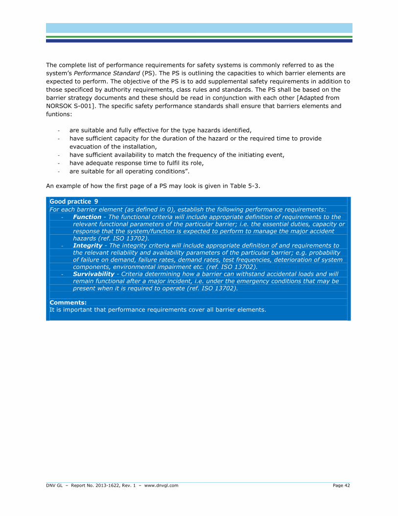
DNV GL – Report No. 2013-1622, Rev. 1 – www.dnvgl.com Page 42
The complete list of performance requirements for safety systems is commonly referred to as the
system’s Performance Standard (PS). The PS is outlining the capacities to which barrier elements are
expected to perform. The objective of the PS is to add supplemental safety requirements in addition to
those specificed by authority requirements, class rules and standards. The PS shall be based on the
barrier strategy documents and these should be read in conjunction with each other [Adapted from
NORSOK S-001]. The specific safety performance standards shall ensure that barriers elements and
funtions:
- are suitable and fully effective for the type hazards identified,
- have sufficient capacity for the duration of the hazard or the required time to provide
evacuation of the installation,
- have sufficient availability to match the frequency of the initiating event,
- have adequate response time to fulfil its role,
- are suitable for all operating conditions”.
An example of how the first page of a PS may look is given in Table 5-3.
Good practice 9 For each barrier element (as defined in 0), establish the following performance requirements:
- Function - The functional criteria will include appropriate definition of requirements to the relevant functional parameters of the particular barrier; i.e. the essential duties, capacity or response that the system/function is expected to perform to manage the major accident
hazards (ref. ISO 13702).
- Integrity - The integrity criteria will include appropriate definition of and requirements to the relevant reliability and availability parameters of the particular barrier; e.g. probability of failure on demand, failure rates, demand rates, test frequencies, deterioration of system components, environmental impairment etc. (ref. ISO 13702).
- Survivability - Criteria determining how a barrier can withstand accidental loads and will remain functional after a major incident, i.e. under the emergency conditions that may be
present when it is required to operate (ref. ISO 13702). Comments: It is important that performance requirements cover all barrier elements.

DNV GL – Report No. 2013-1622, Rev. 1 – www.dnvgl.com Page 43
Table 5-3: Example of PS first page
PS Active Fire Protection
Installation Performance standard (PS) ID
Document number
Issue No. Revision request no. Date Prepared by Verified
by Approved by
1 04.10.2013 EKO
Some Barrier elements commonly categorized under “Active Fire Protection”
'The equipment associated with this performance standard comprises: - Fire pump systems; - Fire water ring main and distribution pipework; - Fire hydrants, hoses and fire water monitors; - Water spray/ foam deluge systems - Water mist systems; - Helideck and refuelling fixed foam system;
- Dual agent skids for the helideck (powder and foam); - Aragonite extinguishing systems
PS Hierarchy
Typical examples of “Role of barrier elements”
The role (barrier sub-function) of barrier elements is to provide quick and reliable means of extinguishing fires and to limit potential escalation. This includes: - Extinguishing fires; - Controlling the spread of fires and preventing escalation by cooling structures and hydrocarbon containing equipment;
- - Reducing explosion overpressures.
Relevant hazardous events from Bow-Tie Prevention / mitigation Bow-Tie
Shallow gas blowout Mitigation XX
Etc. Etc. Etc.
Interface & interactions with other safety
systems Function and reason
PS
number
Fire detection Start of fire pumps upon
confirmed fire XX
Extinguish fires and provide protection to structure and equipment
Other means of fire fighting
Waterfog systems
Dual agent systems
Argonite systems
Portable foam systems
FW pump systems, ring main & distribution pipework to provide required amount of FW to
fires
Manual application of FW to fires
Fire hoses Monitors
Fixed FW systems with automated initiation
Foam systems
Sprinkler system
Deluge systems
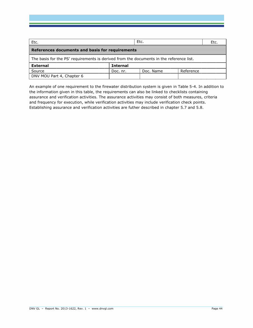
DNV GL – Report No. 2013-1622, Rev. 1 – www.dnvgl.com Page 44
Etc. Etc. Etc.
References documents and basis for requirements
The basis for the PS’ requirements is derived from the documents in the reference list.
External Internal
Source Doc. nr. Doc. Name Reference
DNV MOU Part 4, Chapter 6
An example of one requirement to the firewater distribution system is given in Table 5-4. In addition to
the information given in this table, the requirements can also be linked to checklists containing
assurance and verification activities. The assurance activities may consist of both measures, criteria
and frequency for execution, while verification activities may include verification check points.
Establishing assurance and verification activities are futher described in chapter 5.7 and 5.8.
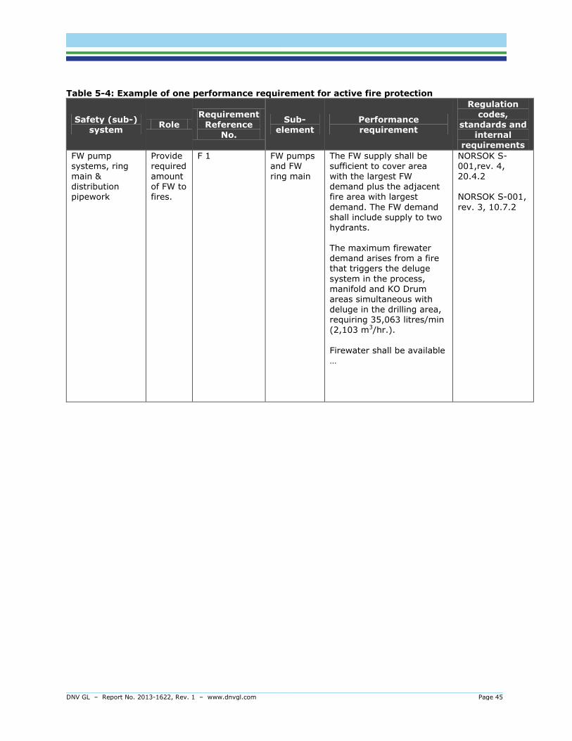
DNV GL – Report No. 2013-1622, Rev. 1 – www.dnvgl.com Page 45
Table 5-4: Example of one performance requirement for active fire protection
Safety (sub-) system
Role Requirement
Reference No.
Sub-element
Performance requirement
Regulation codes,
standards and internal
requirements
FW pump systems, ring main & distribution pipework
Provide required amount of FW to fires.
F 1 FW pumps and FW ring main
The FW supply shall be sufficient to cover area with the largest FW demand plus the adjacent fire area with largest
demand. The FW demand shall include supply to two hydrants. The maximum firewater demand arises from a fire that triggers the deluge
system in the process, manifold and KO Drum areas simultaneous with deluge in the drilling area, requiring 35,063 litres/min (2,103 m3/hr.).
Firewater shall be available …
NORSOK S-001,rev. 4, 20.4.2 NORSOK S-001,
rev. 3, 10.7.2

DNV GL – Report No. 2013-1622, Rev. 1 – www.dnvgl.com Page 46
Good practice 10 Document the performance requirements in performance standards.
Comments: Performance requirements should preferably be established as an integrated part of the design and construction process, as the decisions on what safety systems to install and what specifications they should meet are made during this phase. When performance requirements are established for rigs in operation this may be carried out as a facilitated process, with involvement from relevant personnel. Regulatory requirement can be used
as a starting point before adding the rig specific requirements. In any case, reference should be
given to the regulation, or other documentation, that is the basis for establishing the requirement. In order to facilitate follow-up of the established requirements during operations the performance requirements should be linked to assurance and verification related information. A good way of doing this is to include the assurance measures and criteria and verification activity (see sect 6 for
details) with frequency in the performance standard document. The columns included in the PS may correspond to the bullet points below.
Performance requirement: - Role/function
- Barrier Element - Req. ID - Performance
requirement
- Ref.
Assurance related information: - Assurance measure No.
- Assurance measure - Assurance criteria - Assurance frequency - Responsible party
Verification related information - Verification activity No. - Verification activity
- Verification frequency
Link to barrier analysis: - Comments
- Applicable for Bow-Tie No.
- Corresponding barrier function
- Equipment group fulfilling this barrier element
5.3.1 Performance requirements for operational barrier elements
Performance requirements for operational barrier elements are not as easily obtained as for technical
barrier elements. The main objective with managing operational barrier elements is to increase human
reliability and reduce human errors, by ensuring performance according to established performance
requirements.
As with technical barrier elements, a pre-requisite for managing operational barrier elements is that
they are identified. If some sort of barrier analysis has been performed they may include operational
barrier elements or give indications of barrier functions in which operational barrier elements performs
an important function. Bow-Tie’s often just describe operational barrier elements using brief task
descriptions or references to relevant procedures. If so, a more detailed review of the tasks involved in
operational barrier elements should be obtained.
Task analysis is a well-established method for task description (Kirwan & Ainsworth, 1992). It basically
refers to a set of techniques used to understand tasks by breaking operational goals into a set of tasks
and sub-tasks or actions. The operational goal, in barrier terms, translates to the role or function of
one or more operational barrier elements. There are different ways of documenting task analysis –
some of the most common are task hierarchies, task tables or as process flow diagrams. A task
analysis captures both cognitive and manual actions required to perform a task. Describing the
cognitive (i.e. mental) actions is necessary to further understand how manual actions are performed.
This is illustrated in Figure 3-3, and refers to actions such as detection and diagnosis of events, as well
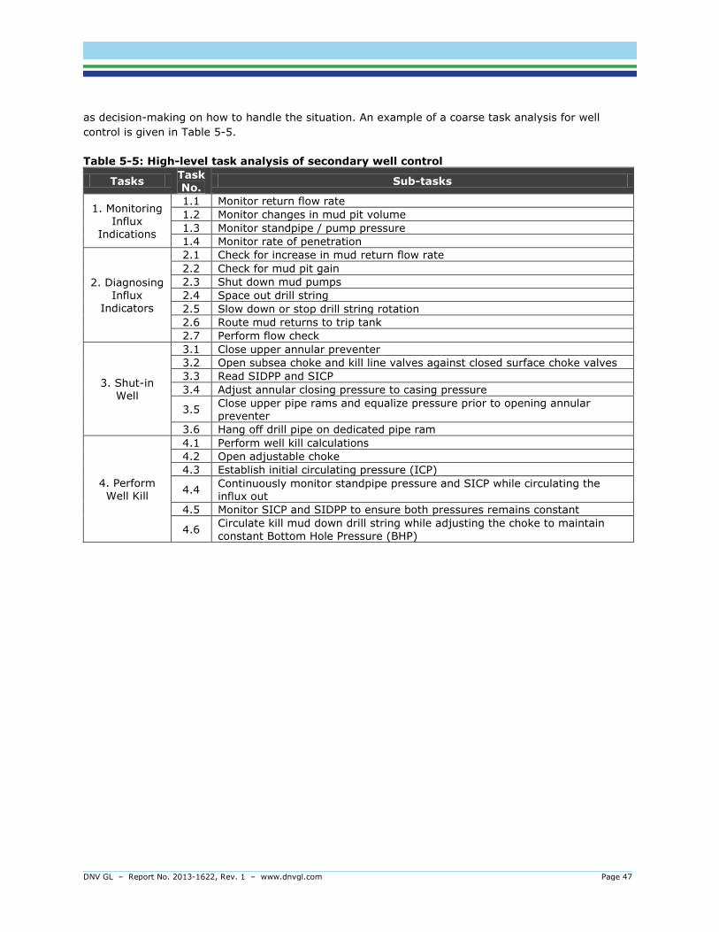
DNV GL – Report No. 2013-1622, Rev. 1 – www.dnvgl.com Page 47
as decision-making on how to handle the situation. An example of a coarse task analysis for well
control is given in Table 5-5.
Table 5-5: High-level task analysis of secondary well control
Tasks Task No.
Sub-tasks
1. Monitoring Influx
Indications
1.1 Monitor return flow rate
1.2 Monitor changes in mud pit volume
1.3 Monitor standpipe / pump pressure
1.4 Monitor rate of penetration
2. Diagnosing Influx
Indicators
2.1 Check for increase in mud return flow rate
2.2 Check for mud pit gain
2.3 Shut down mud pumps
2.4 Space out drill string
2.5 Slow down or stop drill string rotation
2.6 Route mud returns to trip tank
2.7 Perform flow check
3. Shut-in Well
3.1 Close upper annular preventer
3.2 Open subsea choke and kill line valves against closed surface choke valves
3.3 Read SIDPP and SICP
3.4 Adjust annular closing pressure to casing pressure
3.5 Close upper pipe rams and equalize pressure prior to opening annular preventer
3.6 Hang off drill pipe on dedicated pipe ram
4. Perform Well Kill
4.1 Perform well kill calculations
4.2 Open adjustable choke
4.3 Establish initial circulating pressure (ICP)
4.4 Continuously monitor standpipe pressure and SICP while circulating the influx out
4.5 Monitor SICP and SIDPP to ensure both pressures remains constant
4.6 Circulate kill mud down drill string while adjusting the choke to maintain
constant Bottom Hole Pressure (BHP)

DNV GL – Report No. 2013-1622, Rev. 1 – www.dnvgl.com Page 48
The task analysis itself is mainly a method for obtaining sufficient task descriptions allowing for further
evaluations. It is commonly used as part of a larger assessment, such as workload assessments,
human reliability assessments, human error identification, and HMI reviews. An excellent task analysis
method which fits the need for barrier management is called Safety Critical Task Analysis (SCTA).
Guidance for SCTA can be downloaded free of charge on http://www.energyinst.org/home.
Good practice 11
Perform a (safety critical) task analysis to identify and describe operational barrier elements.
Comments:
- Review Bow-Tie’s, risk analysis, safety studies, procedures, or other relevant documentation to identify operational barrier elements (and other safety critical tasks) per area on the rig.
- Describe operational barrier elements in sufficient detail and include or refer to these descriptions in relevant documents (e.g. performance standards, barrier strategies).
- Document link between operational barrier elements, other barrier elements, barrier functions, hazards, hazardous events, rig areas etc., for example through the barrier analysis.
- Not all operational barrier elements needs be analysed in detail. It is therefore useful to establish a set of criteria for which operational barrier elements should be subject to task analysis. Examples of criteria can be:
- Task criticality, such as importance for barrier function performance or
consequence of human error on accident prevention or mitigation.
- Task complexity, such as number and sequence of task steps, durance of task, equipment involved, amount of information to be processed, number of people involved etc.
- For highly critical tasks, human errors and unsafe actions should be identified so that they
can be systematically managed and reduced.
Task analysis is often based on descriptions of major accident scenarios. As a start, the question is often “what does operators have to do to prevent or mitigate this event?”. Several sources of information can be used, but it should always include input from the end-user actually performing the task. Walk-through-talk-through, workshops and observations are good arenas for data
collection.
The next step is to use the task analysis, or other available task descriptions, for establishing
performance requirements for operational barrier elements.
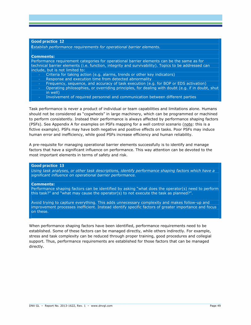
DNV GL – Report No. 2013-1622, Rev. 1 – www.dnvgl.com Page 49
Good practice 12 Establish performance requirements for operational barrier elements.
Comments: Performance requirement categories for operational barrier elements can be the same as for
technical barrier elements (i.e. function, integrity and survivability). Topics to be addressed can include, but is not limited to:
- Criteria for taking action (e.g. alarms, trends or other key indicators) - Response and execution time from detected abnormality - Frequency, sequence, and accuracy of task execution (e.g. for BOP or EDS activation) - Operating philosophies, or overriding principles, for dealing with doubt (e.g. if in doubt, shut
in well) - Involvement of required personnel and communication between different parties
Task performance is never a product of individual or team capabilities and limitations alone. Humans
should not be considered as “cogwheels” in large machinery, which can be programmed or machined
to perform consistently. Instead their performance is always affected by performance shaping factors
(PSFs). See Appendix A for examples on PSFs mapping for a well control scenario (note: this is a
fictive example). PSFs may have both negative and positive effects on tasks. Poor PSFs may induce
human error and inefficiency, while good PSFs increase efficiency and human reliability.
A pre-requisite for managing operational barrier elements successfully is to identify and manage
factors that have a significant influence on performance. This way attention can be devoted to the
most important elements in terms of safety and risk.
Good practice 13 Using task analyses, or other task descriptions, identify performance shaping factors which have a significant influence on operational barrier performance.
Comments: Performance shaping factors can be identified by asking “what does the operator(s) need to perform this task?” and “what may cause the operator(s) to not execute the task as planned?”.
Avoid trying to capture everything. This adds unnecessary complexity and makes follow-up and improvement processes inefficient. Instead identify specific factors of greater importance and focus on these.
When performance shaping factors have been identified, performance requirements need to be
established. Some of these factors can be managed directly, while others indirectly. For example,
stress and task complexity can be reduced through proper training, good procedures and collegial
support. Thus, performance requirements are established for those factors that can be managed
directly.

DNV GL – Report No. 2013-1622, Rev. 1 – www.dnvgl.com Page 50
Examples of requirement topics for PSFs are given in Table 5-6. Note that other PSFs may also be
relevant.
Table 5-6: Example of topics relevant for identifying performance requirements
Performance shaping factors
Requirement topics
Procedures
- Accuracy (e.g. step sequences) - Relevancy of content (e.g. exclude irrelevant information) - Availability (e.g. marking/labelling, location)
- Updating (e.g. revision control, MoC) - Owner (e.g. authorization to modify and distribute)
- Usability (e.g. support with drawings, figures, tables) - Frequency of use/familiarity (e.g. level of detail) - Use of highlighting (e.g. critical information)
Competence and training
- Formal certificates (e.g. for certain tasks)
- Verification of competence (e.g. before task or job assignment) - Documentation of training needs (e.g. for competence
development) - Follow-up of personnel in operations (e.g. seniors coaching
junior staff) - On-the-job (OJT) training (e.g. for normal operations)
- Simulator training (e.g. for rare or abnormal events)
Human-machine
interface (HMI) and equipment
- Marking of equipment and controls (e.g. clear labelling) - Consistency (e.g. use of colours and symbols)
- Availability (e.g. access to panels and displays) - Familiarization (e.g. knowledge about controls) - Visibility (e.g. of system status, such as overrides)
- Fault tolerance (e.g. avoid unintentional activation)
Good practice 14 Establish and document performance requirements for performance shaping factors. Comments: In addition to the task analysis, requirements can be collected from different sources:
- Regulatory requirements (e.g. PSA) - DNV GL Class rules (mostly for technical PSFs, such as HMI) - International standards (e.g. ISO, NORSOK. Mostly for technical PSFs, such as HMI) - Already existing internal requirements (e.g. from procedures, manuals and operating
philosophies) - Crisis Intervention and Operability (CRIOP) method
Some high level requirements can apply to performance shaping factors across all operational barrier elements, such as requirements about mapping of training needs. More detailed requirements may only apply for specific operational barrier elements, such as location or marking of certain equipment.
Careful consideration should be made for how and where to document the performance requirements. One solution is to document detailed requirements together with Performance Standards for associated technical barrier elements. For example, requirements for competence,
procedures and HMI specifically associated with well control can be documented in a performance standard for “Well Control Systems”. More general requirements which can be applied to several
operational barrier elements can be gathered into one dedicated performance standard.

DNV GL – Report No. 2013-1622, Rev. 1 – www.dnvgl.com Page 51
Figure 5-2 summarizes the Good Practices for identifying and establishing for operational barrier
elements. Note that the same approach can also be used for and include other safety critical tasks.
Figure 5-2 Process for establishing operational barrier element performance requirements

DNV GL – Report No. 2013-1622, Rev. 1 – www.dnvgl.com Page 52
5.4 Prevent degradation of barrier performance
Barriers are designed to prevent and control major accident risks. Requirements to performance of
barrier and barrier elements should be established in the performance standard. Barriers will always be
subjected to deterioration and unsafe acts causing holes in the barriers. Activities to ensure
performance must be managed in a systematic way. This management is shown in Figure 5-3 and
described in this chapter.
Before establishing activities to ensure performance critical degradation and safety critical failures
must be identified. Acceptance criteria for deterioration of barrier functionality must be established. To
prevent failure and degradation efforts must be made to maintain barrier condition and performance
throughout the lifetime of the installation.
For technical barriers this is done partly by choosing the right maintenance strategy and establishing a
maintenance program based on the Failure Mode and Effect Analysis (FMECA) and associated analysis
as Reliability centred maintenance (RCM) Risk based Inspection (RBI). Based on output from these
analysis a maintenance philosophy should be choose to state activities to be performed and interval
(see chapter 05.5).
For operational barriers a Human Reliability Analysis (HRA) can identify and give input to safety critical
procedures, training needs, workload issues and other performance shaping factors which have
influence on task performance (see chapter 5.6). For barriers to function as required and when
needed, activities to ensure barrier elements to fulfil performance requirements must be in place (see
chapter 5.7 ) and also verification activities to ensure processes to manage barrier performance are in
place and performed as intended (see chapter 5.8) must be in place.
Figure 5-3: Management of barrier performance
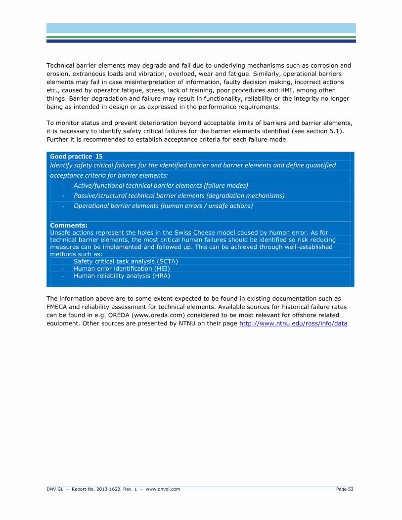
DNV GL – Report No. 2013-1622, Rev. 1 – www.dnvgl.com Page 53
Technical barrier elements may degrade and fail due to underlying mechanisms such as corrosion and
erosion, extraneous loads and vibration, overload, wear and fatigue. Similarly, operational barriers
elements may fail in case misinterpretation of information, faulty decision making, incorrect actions
etc., caused by operator fatigue, stress, lack of training, poor procedures and HMI, among other
things. Barrier degradation and failure may result in functionality, reliability or the integrity no longer
being as intended in design or as expressed in the performance requirements.
To monitor status and prevent deterioration beyond acceptable limits of barriers and barrier elements,
it is necessary to identify safety critical failures for the barrier elements identified (see section 5.1).
Further it is recommended to establish acceptance criteria for each failure mode.
Good practice 15 Identify safety critical failures for the identified barrier and barrier elements and define quantified
acceptance criteria for barrier elements:
- Active/functional technical barrier elements (failure modes)
- Passive/structural technical barrier elements (degradation mechanisms)
- Operational barrier elements (human errors / unsafe actions)
Comments: Unsafe actions represent the holes in the Swiss Cheese model caused by human error. As for technical barrier elements, the most critical human failures should be identified so risk reducing
measures can be implemented and followed up. This can be achieved through well-established
methods such as: - Safety critical task analysis (SCTA) - Human error identification (HEI) - Human reliability analysis (HRA)
The information above are to some extent expected to be found in existing documentation such as
FMECA and reliability assessment for technical elements. Available sources for historical failure rates
can be found in e.g. OREDA (www.oreda.com) considered to be most relevant for offshore related
equipment. Other sources are presented by NTNU on their page http://www.ntnu.edu/ross/info/data

DNV GL – Report No. 2013-1622, Rev. 1 – www.dnvgl.com Page 54
When establishing acceptance criteria, the historical values should be consulted to establish realistic
values. In addition to the above, data either used or resulting from other documentation, such as risk
assessment, emergency preparedness assessment, emergency procedures etc. may form basis for the
criteria. Typical safety critical failures for technical elements are shown in Table 5-7. Examples of
unsafe actions for operational barrier elements are described in Table 3-3.
Table 5-7: Examples of safety critical failures for technical elements
Performance
standard
Barrier element/
SCE Safety critical failure
Acceptance criteria (Target
Failure Fraction)
Fire and gas detection
Flame detectors The detector does not give correct signal to the F&G logic when tested
1%
Manual call point push button
The F&G logic does not receive a signal from the call point when activated
0,5%
Active fire
fighting
Fire water pump unit, start
The fire water pump unit fails to start on signal
0.5 %
Fire water pump capacity
The fire water pump delivers less than 90 % of design capacity
1 %
Well control Blow out preventer
Leakage through one of the barrier valves observed by measured
pressure loss over time (i.e., if stable
pressure then no safety critical failure)
Trend
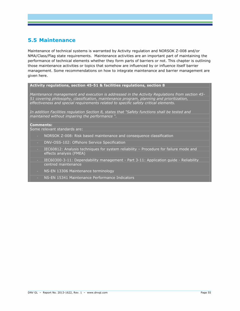
DNV GL – Report No. 2013-1622, Rev. 1 – www.dnvgl.com Page 55
5.5 Maintenance
Maintenance of technical systems is warranted by Activity regulation and NORSOK Z-008 and/or
NMA/Class/Flag state requirements. Maintenance activities are an important part of maintaining the
performance of technical elements whether they form parts of barriers or not. This chapter is outlining
those maintenance activities or topics that somehow are influenced by or influence itself barrier
management. Some recommendations on how to integrate maintenance and barrier management are
given here.
Activity regulations, section 45-51 & facilities regulations, section 8
Maintenance management and execution is addressed in the Activity Regulations from section 45-51 covering philosophy, classification, maintenance program, planning and prioritization, effectiveness and special requirements related to specific safety critical elements.
In addition Facilities regulation Section 8, states that “Safety functions shall be tested and maintained without impairing the performance “.
Comments: Some relevant standards are:
- NORSOK Z-008: Risk based maintenance and consequence classification
- DNV-OSS-102: Offshore Service Specification
- IEC60812: Analysis techniques for system reliability – Procedure for failure mode and effects analysis (FMEA)
- IEC60300-3-11: Dependability management - Part 3-11: Application guide - Reliability centred maintenance
- NS-EN 13306 Maintenance terminology
- NS-EN 15341 Maintenance Performance Indicators
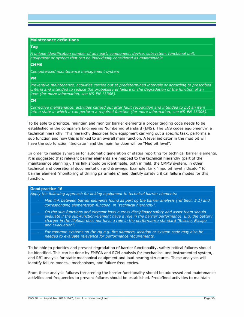
DNV GL – Report No. 2013-1622, Rev. 1 – www.dnvgl.com Page 56
Maintenance definitions
Tag
A unique identification number of any part, component, device, subsystem, functional unit, equipment or system that can be individually considered as maintainable
CMMS
Computerised maintenance management system
PM
Preventive maintenance, activities carried out at predetermined intervals or according to prescribed
criteria and intended to reduce the probability of failure or the degradation of the function of an item (for more information, see NS-EN 13306).
CM
Corrective maintenance, activities carried out after fault recognition and intended to put an item into a state in which it can perform a required function (for more information, see NS-EN 13306).
To be able to prioritize, maintain and monitor barrier elements a proper tagging code needs to be
established in the company's Engineering Numbering Standard (ENS). The ENS codes equipment in a
technical hierarchy. This hierarchy describes how equipment carrying out a specific task, performs a
sub function and how this is linked to an overall main function. A level indicator in the mud pit will
have the sub function “Indicator” and the main function will be “Mud pit level”.
In order to realize synergies for automatic generation of status reporting for technical barrier elements,
it is suggested that relevant barrier elements are mapped to the technical hierarchy (part of the
maintenance planning). This link should be identifiable, both in field, the CMMS system, in other
technical and operational documentation and drawings. Example: Link “mud pit level indicator” to
barrier element “monitoring of drilling parameters” and identify safety critical failure modes for this
function.
Good practice 16 Apply the following approach for linking equipment to technical barrier elements:
- Map link between barrier elements found as part og the barrier analysis (ref Sect. 5.1) and
corresponding element/sub-function in “technical hierarchy”.
- On the sub-functions and element level a cross disciplinary safety and asset team should evaluate if the sub-function/element have a role in the barrier performance. E.g. the battery charger in the lifeboat does not have a role in the performance standard “Rescue, Escape
and Evacuation”.
- For common systems on the rig e.g. fire dampers, location or system code may also be needed to evaluate relevance for performance requirements.
To be able to priorities and prevent degradation of barrier functionality, safety critical failures should
be identified. This can be done by FMECA and RCM analysis for mechanical and instrumented system,
and RBI analysis for static mechanical equipment and load bearing structures. These analyses will
identify failure modes, -mechanisms, and failure frequencies.
From these analysis failures threatening the barrier functionality should be addressed and maintenance
activities and frequencies to prevent failures should be established. Predefined activities to maintain
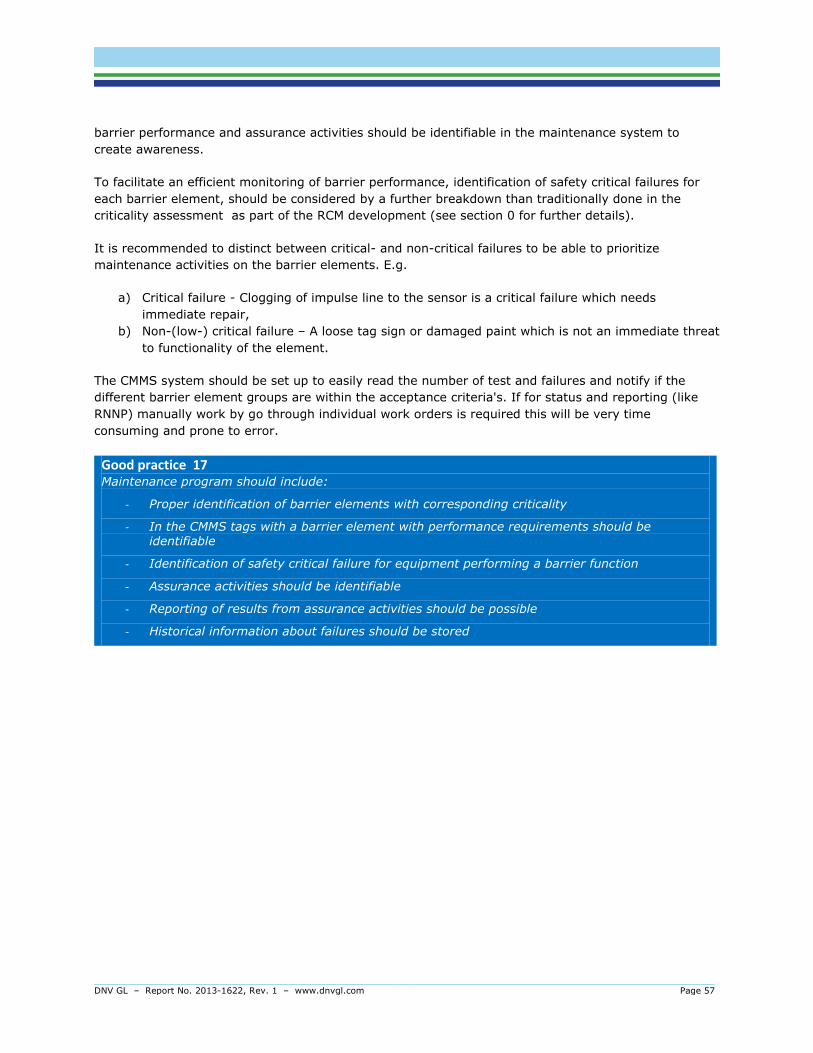
DNV GL – Report No. 2013-1622, Rev. 1 – www.dnvgl.com Page 57
barrier performance and assurance activities should be identifiable in the maintenance system to
create awareness.
To facilitate an efficient monitoring of barrier performance, identification of safety critical failures for
each barrier element, should be considered by a further breakdown than traditionally done in the
criticality assessment as part of the RCM development (see section 0 for further details).
It is recommended to distinct between critical- and non-critical failures to be able to prioritize
maintenance activities on the barrier elements. E.g.
a) Critical failure - Clogging of impulse line to the sensor is a critical failure which needs
immediate repair,
b) Non-(low-) critical failure – A loose tag sign or damaged paint which is not an immediate threat
to functionality of the element.
The CMMS system should be set up to easily read the number of test and failures and notify if the
different barrier element groups are within the acceptance criteria's. If for status and reporting (like
RNNP) manually work by go through individual work orders is required this will be very time
consuming and prone to error.
Good practice 17 Maintenance program should include:
- Proper identification of barrier elements with corresponding criticality
- In the CMMS tags with a barrier element with performance requirements should be identifiable
- Identification of safety critical failure for equipment performing a barrier function
- Assurance activities should be identifiable
- Reporting of results from assurance activities should be possible
- Historical information about failures should be stored
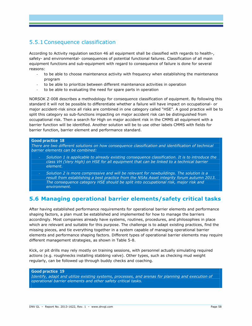
DNV GL – Report No. 2013-1622, Rev. 1 – www.dnvgl.com Page 58
5.5.1 Consequence classification
According to Activity regulation section 46 all equipment shall be classified with regards to health-,
safety- and environmental- consequences of potential functional failures. Classification of all main
equipment functions and sub-equipment with regard to consequence of failure is done for several
reasons:
- to be able to choose maintenance activity with frequency when establishing the maintenance
program
- to be able to prioritize between different maintenance activities in operation
- to be able to evaluating the need for spare parts in operation
NORSOK Z-008 describes a methodology for consequence classification of equipment. By following this
standard it will not be possible to differentiate whether a failure will have impact on occupational- or
major accident-risk since all risks are combined in one category called “HSE”. A good practice will be to
split this category so sub-functions impacting on major accident risk can be distinguished from
occupational risk. Then a search for High on major accident risk in the CMMS all equipment with a
barrier function will be identified. Another solution will be to use other labels CMMS with fields for
barrier function, barrier element and performance standard.
Good practice 18 There are two different solutions on how consequence classification and identification of technical barrier elements can be combined:
- Solution 1 is applicable to already existing consequence classification. It is to introduce the class VH (Very High) on HSE for all equipment that can be linked to a technical barrier element.
- Solution 2 is more compressive and will be relevant for newbuildings. The solution is a result from establishing a best practice from the NSAs Asset integrity forum autumn 2013. The consequence category HSE should be split into occupational risk, major risk and environment.
5.6 Managing operational barrier elements/safety critical tasks
After having established performance requirements for operational barrier elements and performance
shaping factors, a plan must be established and implemented for how to manage the barriers
accordingly. Most companies already have systems, routines, procedures, and philosophies in place
which are relevant and suitable for this purpose. The challenge is to adapt existing practices, find the
missing pieces, and tie everything together in a system capable of managing operational barrier
elements and performance shaping factors. Different types of operational barrier elements may require
different management strategies, as shown in Table 5-8.
Kick, or pit drills may rely mostly on training sessions, with personnel actually simulating required
actions (e.g. roughnecks installing stabbing valve). Other types, such as checking mud weight
regularly, can be followed up through buddy checks and coaching.
Good practice 19 Identify, adapt and utilize existing systems, processes, and arenas for planning and execution of operational barrier elements and other safety critical tasks.
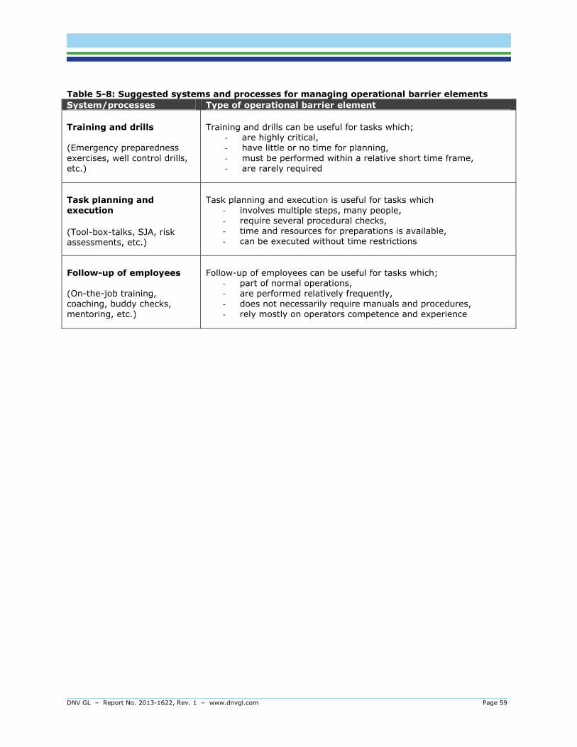
DNV GL – Report No. 2013-1622, Rev. 1 – www.dnvgl.com Page 59
Table 5-8: Suggested systems and processes for managing operational barrier elements
System/processes Type of operational barrier element
Training and drills (Emergency preparedness
exercises, well control drills, etc.)
Training and drills can be useful for tasks which; - are highly critical, - have little or no time for planning,
- must be performed within a relative short time frame, - are rarely required
Task planning and
execution
(Tool-box-talks, SJA, risk assessments, etc.)
Task planning and execution is useful for tasks which
- involves multiple steps, many people, - require several procedural checks, - time and resources for preparations is available, - can be executed without time restrictions
Follow-up of employees (On-the-job training, coaching, buddy checks, mentoring, etc.)
Follow-up of employees can be useful for tasks which; - part of normal operations, - are performed relatively frequently, - does not necessarily require manuals and procedures, - rely mostly on operators competence and experience

DNV GL – Report No. 2013-1622, Rev. 1 – www.dnvgl.com Page 60
5.6.1 Training and drills
Some important operational barrier elements are part of the expected responses of the operators to
accident initiators, commonly triggered by alarms and other detected abnormalities. These are
relatively rare events which imply that certain operational barrier elements are not subject to regular
on-the-job practice. This is particularly true for operational barrier elements which are part of
mitigating barrier functions, such as tasks part of secondary well control (e.g. BOP activation, choke &
kill etc.), emergency disconnect, search & rescue, and firefighting. To compensate, different types of
training and drills can be effective means to ensure that operational barrier elements perform as
intended when needed.
Good practice 20 Implement a training program for operational barrier elements. Comments: The training program should take the following topics into consideration (ref. also Table 8-1):
- Identify which operational barrier elements require training to meet performance requirements, e.g. by reviewing the barrier analysis (if performed).
- Develop learning goals to reflect and define purpose of the training.
- Learning goals should include technical as well as interpersonal/social skills (e.g.
teamwork).
- Perform training evaluations to measure learning effects and achievement of learning goals.
- Evaluations should include, but is not limited to, performance measures related to response time, accuracy, execution sequence, deviations and errors, incl. their causes.
- Measures of performance should be made against performance requirements, including a set of clear and pre-defined criteria.
- Systematically update and improve training program based on training evaluations. Key
success factors should be reinforced.
- Ensure sufficient realism when performing drills, e.g. by use of scenario based training and simulator centres.
- Scenarios should reflect the area specific barrier strategies
- Consider frequency of training/drills against complexity and criticality of task (operational barrier element).
Note: Many companies already perform several types of drills (e.g. pit, kick & choke drills) and
emergency preparedness exercises. To avoid introducing overlapping training initiatives, a GAP
analysis can be performed to examine whether relevant operational barrier elements have been
covered. Also, existing training should reflect the barrier strategy, and links to barrier functions and
hazards should be made clear.
Note: The International Association of Oil & Gas Producers (OGP, 2012) has issued an excellent report
on recommendations for enhancements to well control training, examination and verification. Another
report on safety critical team skills is due early 2014. This introduces the concept of Crew Resource
Management, a well-established training concept in the aviation industry which is already in use by
some rig owners. NORSOK D-010 also stipulates requirements and guidance on well control drills.
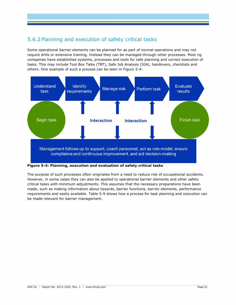
DNV GL – Report No. 2013-1622, Rev. 1 – www.dnvgl.com Page 61
5.6.2 Planning and execution of safety critical tasks
Some operational barrier elements can be planned for as part of normal operations and may not
require drills or extensive training. Instead they can be managed through other processes. Most rig
companies have established systems, processes and tools for safe planning and correct execution of
tasks. This may include Tool Box Talks (TBT), Safe Job Analysis (SJA), handovers, checklists and
others. One example of such a process can be seen in Figure 5-4:
Figure 5-4: Planning, execution and evaluation of safety critical tasks
The purpose of such processes often originates from a need to reduce risk of occupational accidents.
However, in some cases they can also be applied to operational barrier elements and other safety
critical tasks with minimum adjustments. This assumes that the necessary preparations have been
made, such as making information about hazards, barrier functions, barrier elements, performance
requirements and easily available. Table 5-9 shows how a process for task planning and execution can
be made relevant for barrier management.
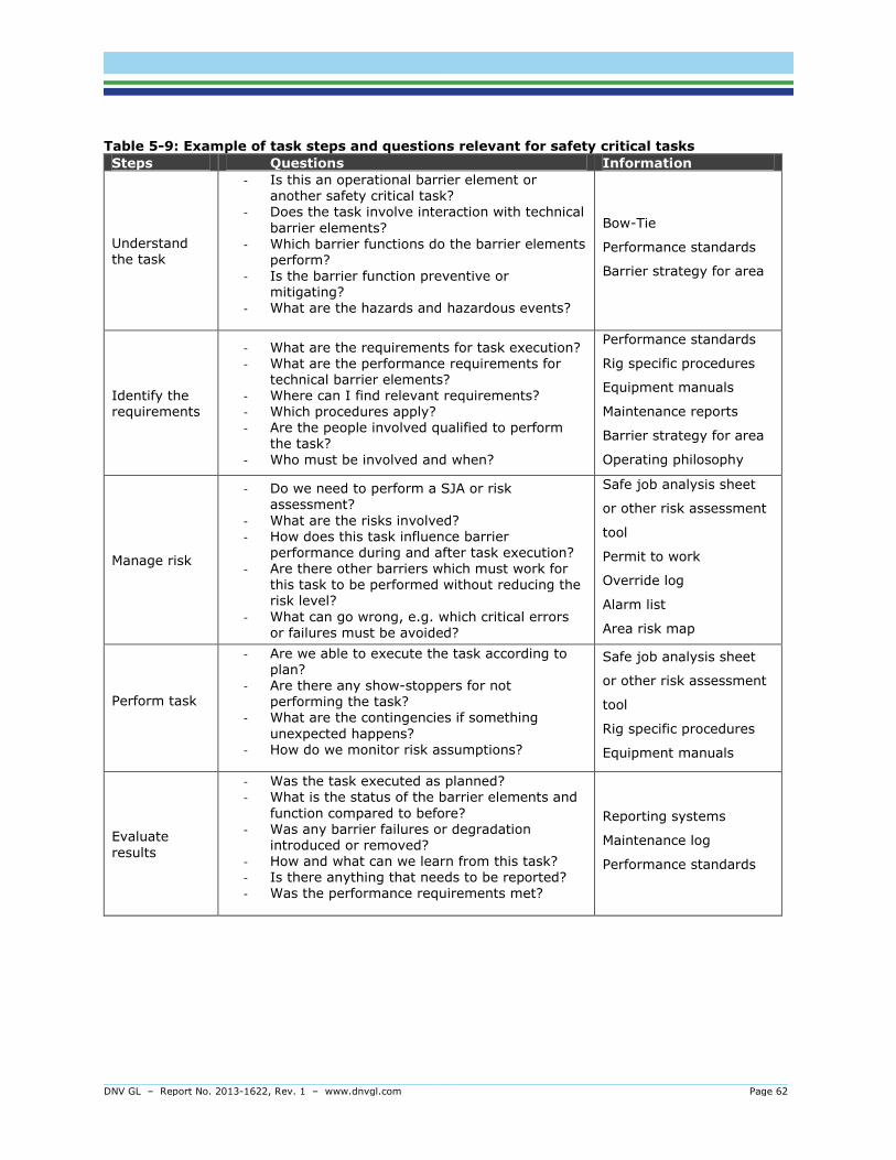
DNV GL – Report No. 2013-1622, Rev. 1 – www.dnvgl.com Page 62
Table 5-9: Example of task steps and questions relevant for safety critical tasks
Steps Questions Information
Understand the task
- Is this an operational barrier element or another safety critical task?
- Does the task involve interaction with technical
barrier elements? - Which barrier functions do the barrier elements
perform? - Is the barrier function preventive or
mitigating? - What are the hazards and hazardous events?
Bow-Tie
Performance standards
Barrier strategy for area
Identify the requirements
- What are the requirements for task execution? - What are the performance requirements for
technical barrier elements? - Where can I find relevant requirements? - Which procedures apply? - Are the people involved qualified to perform
the task?
- Who must be involved and when?
Performance standards
Rig specific procedures
Equipment manuals
Maintenance reports
Barrier strategy for area
Operating philosophy
Manage risk
- Do we need to perform a SJA or risk assessment?
- What are the risks involved? - How does this task influence barrier
performance during and after task execution? - Are there other barriers which must work for
this task to be performed without reducing the risk level?
- What can go wrong, e.g. which critical errors or failures must be avoided?
Safe job analysis sheet
or other risk assessment
tool
Permit to work
Override log
Alarm list
Area risk map
Perform task
- Are we able to execute the task according to plan?
- Are there any show-stoppers for not performing the task?
- What are the contingencies if something
unexpected happens? - How do we monitor risk assumptions?
Safe job analysis sheet
or other risk assessment
tool
Rig specific procedures
Equipment manuals
Evaluate
results
- Was the task executed as planned? - What is the status of the barrier elements and
function compared to before? - Was any barrier failures or degradation
introduced or removed? - How and what can we learn from this task? - Is there anything that needs to be reported? - Was the performance requirements met?
Reporting systems
Maintenance log
Performance standards
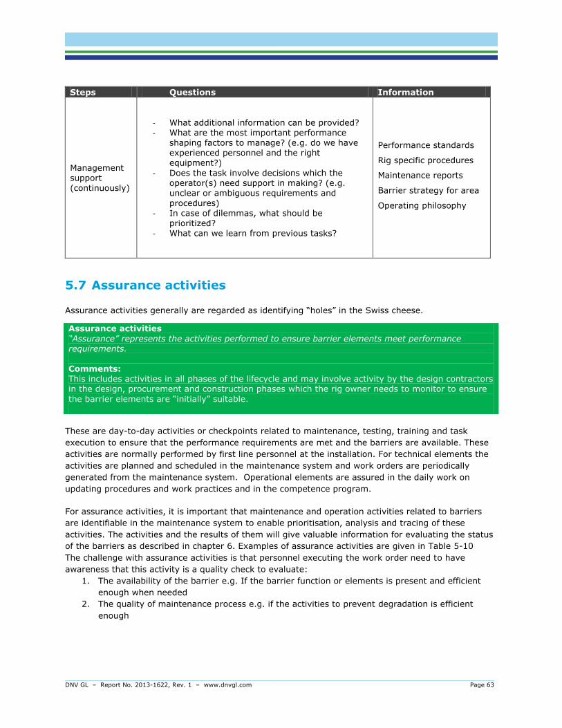
DNV GL – Report No. 2013-1622, Rev. 1 – www.dnvgl.com Page 63
Steps Questions Information
Management support (continuously)
- What additional information can be provided? - What are the most important performance
shaping factors to manage? (e.g. do we have experienced personnel and the right equipment?)
- Does the task involve decisions which the operator(s) need support in making? (e.g. unclear or ambiguous requirements and
procedures) - In case of dilemmas, what should be
prioritized? - What can we learn from previous tasks?
Performance standards
Rig specific procedures
Maintenance reports
Barrier strategy for area
Operating philosophy
5.7 Assurance activities
Assurance activities generally are regarded as identifying “holes” in the Swiss cheese.
These are day-to-day activities or checkpoints related to maintenance, testing, training and task
execution to ensure that the performance requirements are met and the barriers are available. These
activities are normally performed by first line personnel at the installation. For technical elements the
activities are planned and scheduled in the maintenance system and work orders are periodically
generated from the maintenance system. Operational elements are assured in the daily work on
updating procedures and work practices and in the competence program.
For assurance activities, it is important that maintenance and operation activities related to barriers
are identifiable in the maintenance system to enable prioritisation, analysis and tracing of these
activities. The activities and the results of them will give valuable information for evaluating the status
of the barriers as described in chapter 6. Examples of assurance activities are given in Table 5-10
The challenge with assurance activities is that personnel executing the work order need to have
awareness that this activity is a quality check to evaluate:
1. The availability of the barrier e.g. If the barrier function or elements is present and efficient
enough when needed
2. The quality of maintenance process e.g. if the activities to prevent degradation is efficient
enough
Assurance activities
“Assurance” represents the activities performed to ensure barrier elements meet performance requirements. Comments: This includes activities in all phases of the lifecycle and may involve activity by the design contractors in the design, procurement and construction phases which the rig owner needs to monitor to ensure
the barrier elements are “initially” suitable.
DNV GL – Report No. 2013-1622, Rev. 1 – www.dnvgl.com Page 64
Since main task for personnel doing the assurance activities normally is to fix equipment, knowledge
about purpose of assurance activities and who to handle a failure on a test with regard to reporting is
necessary.
Good practice 21 Mark (indicate) assurance activities in CMMS. Then personnel executing the Work Order will be aware of purpose and how to handle a test or inspection when it comes to follow-up and reporting.
5.8 Verification activities
Verification activities with reference to Swiss cheese model is to evaluate if the hazard picture has
changed and if the thickness and coverage of the cheese slices are sufficient.
Verification activities
Verification represents the activities to confirm whether the barrier elements will be, are, and remain suitable, or are adequately specified and constructed, and are being maintained in adequate condition to meet the requirements of the Performance Standards.
The purpose of verification is to verify that established processes for managing performance of barriers
are working as intended. Subject for the verification will be to look into e.g. design documentation
compared to as- is, maintenance program, the setup and results of assurance activities, the coverage
of performance requirements. Normally this is performed, either by an independent (3rd) party or a
party not directly responsible for the assurance activity. Verification activities may be carried out on a
fixed interval basis or on demand. Performance requirements, checkpoints for verification, findings and
ranked actions are normally not included in any systems but a simple data base can be a solution.
Good practice 22 Establish a database, or use existing CMMS if possible, for managing performance requirements, incl. related verification activities or checkpoints, findings and actions. Comments:
As part of the verification, all findings/deviations should be ranked according to the effect it has on the safety level, using a set of predefined grades. The ranking will make it easier to prioritize implementation of risk reducing measures (close findings) and improve safety.

DNV GL – Report No. 2013-1622, Rev. 1 – www.dnvgl.com Page 65
A good way of establishing assurance and verification activities or check points is through well
prepared workshops with relevant personnel from the company; system responsible, asset and HSE.
Technical experts on safety systems and class requirements should also be represented. Relevant input
data will be Performance requirements, maintenance program, technical hierarcy, prosedures and
competence matrixs. The assurance activities should comprise frequencies and responsible
unit/manager in order to create a clear link to the maintenance programme. The assurance criteria
should be formulated to clearly determine a pass or fail of the performance requirement and the
instruction on what and how to report should be stated. Examples of verification activities are given
Table 5-10.
Good practice 23 Follow 7 success factors for verification activities:
- Establish “common ground”: Clearly communicate background and objective of the
assessment.
- Ownership: It is important with commitment and involvement from management and local
unit.
- Quality: The results of the verification relays on the quality of the performance
requirements and checkpoint in the PS.
- Competence: High quality level in the survey team.
- Added value – increased safety: Clearly define findings, and practical risk reducing
measures to be implemented.
- Co-operation: A transparent process between survey team and personnel from the asset
being object to verification.
- Learning: Exchange of knowledge and experience.

DN
V G
L
– Report
No.
2013-1
622,
Rev.
1 – w
ww
.dnvgl.com
Page 6
6
Tab
le 5
-10
: Exam
ple
of
assu
ran
ce a
nd
verif
icati
on
acti
vit
ies
Barrie
r
ele
men
t Type of
requireme
nts
Perfo
rm
an
ce r
eq
uir
em
en
ts
Typ
ical
assu
ran
ce a
cti
vit
ies
an
d t
est
meth
od
Desig
n
cap
acit
y
&
info
rm
at
ion
sou
rce
Actu
al
insta
lled
cap
acit
y
(&
in
fo
sou
rce)
Typ
ical
verif
icati
on
acti
vit
ies
Active fir
e
fighting
Fir
e p
um
p
Functionality
Fire w
ate
r syste
m s
hall b
e a
ble
to
pro
vid
e w
ate
r (f
rom
any s
ection o
f
the r
ingm
ain
) in
suffic
ient
quantities t
o t
he larg
est
user
on
the insta
llation p
lus t
he a
dja
cent
are
a w
ith t
he larg
est
dem
and p
lus
to t
wo h
ydra
nts
.
Check f
ire p
um
p c
apacity h
ead
by p
ort
able
flo
w m
ete
r and
pre
ssure
gauge a
t pum
p h
ead.
2,1
03
m3/h
r &
16barg
@
main
deck
ele
vation
2,2
00
m3/h
r &
16barg
@
main
deck
ele
vation
Check t
est
results
and m
ain
tenance
record
.
Integrity
Inhib
its a
nd o
verr
ides s
hall b
e
regis
tere
d a
nd a
n o
verv
iew
shall
be a
vailable
in C
CR.
Enable
d
inhib
its a
nd o
verr
ides s
hall h
ave
constr
ain
ts r
ele
vant
to a
ctivity a
nd
dura
tion.
Check t
hat
instr
uctions
/pro
cedure
s for
use a
nd c
ontr
ol
of in
hib
it a
nd o
verr
ides a
re in
pla
ce a
nd a
dhere
d t
o.
Check t
hat
inhib
its
and o
verr
ides is
regis
tere
d a
nd t
hat
an o
verv
iew
is
available
in C
CR.
Survivability
All a
ctive fir
efighting e
quip
ment
shall b
e p
rote
cte
d a
gain
st
dim
ensio
nin
g e
xplo
sio
ns a
nd fir
es.
Veri
fication o
f auto
matic s
tart
-up
sequence o
f th
e fir
e w
ate
r pum
ps
Check t
hat
fire
wate
r and
centr
alized foam
pum
ps is fir
e
resis
tant
in
accord
ance w
ith
sta
ndard
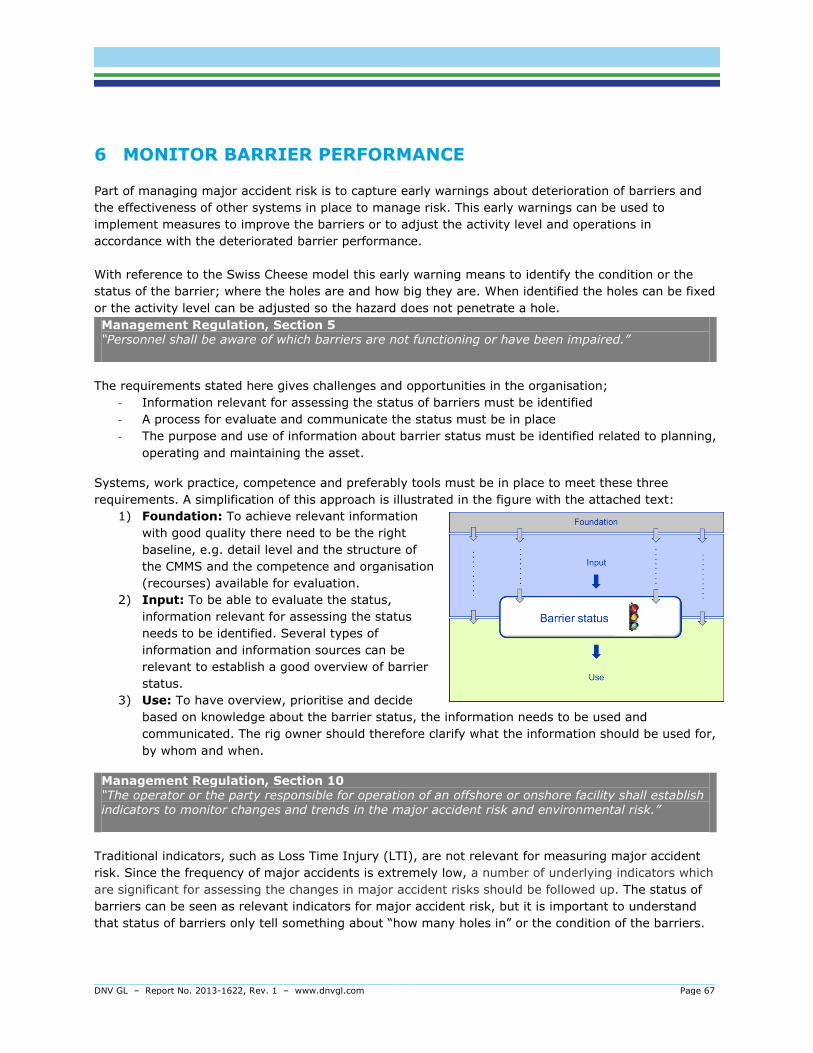
DNV GL – Report No. 2013-1622, Rev. 1 – www.dnvgl.com Page 67
6 MONITOR BARRIER PERFORMANCE
Part of managing major accident risk is to capture early warnings about deterioration of barriers and
the effectiveness of other systems in place to manage risk. This early warnings can be used to
implement measures to improve the barriers or to adjust the activity level and operations in
accordance with the deteriorated barrier performance.
With reference to the Swiss Cheese model this early warning means to identify the condition or the
status of the barrier; where the holes are and how big they are. When identified the holes can be fixed
or the activity level can be adjusted so the hazard does not penetrate a hole.
Management Regulation, Section 5 “Personnel shall be aware of which barriers are not functioning or have been impaired.”
The requirements stated here gives challenges and opportunities in the organisation;
- Information relevant for assessing the status of barriers must be identified
- A process for evaluate and communicate the status must be in place
- The purpose and use of information about barrier status must be identified related to planning,
operating and maintaining the asset.
Systems, work practice, competence and preferably tools must be in place to meet these three
requirements. A simplification of this approach is illustrated in the figure with the attached text:
1) Foundation: To achieve relevant information
with good quality there need to be the right
baseline, e.g. detail level and the structure of
the CMMS and the competence and organisation
(recourses) available for evaluation.
2) Input: To be able to evaluate the status,
information relevant for assessing the status
needs to be identified. Several types of
information and information sources can be
relevant to establish a good overview of barrier
status.
3) Use: To have overview, prioritise and decide
based on knowledge about the barrier status, the information needs to be used and
communicated. The rig owner should therefore clarify what the information should be used for,
by whom and when.
Management Regulation, Section 10 “The operator or the party responsible for operation of an offshore or onshore facility shall establish indicators to monitor changes and trends in the major accident risk and environmental risk.”
Traditional indicators, such as Loss Time Injury (LTI), are not relevant for measuring major accident
risk. Since the frequency of major accidents is extremely low, a number of underlying indicators which
are significant for assessing the changes in major accident risks should be followed up. The status of
barriers can be seen as relevant indicators for major accident risk, but it is important to understand
that status of barriers only tell something about “how many holes in” or the condition of the barriers.

DNV GL – Report No. 2013-1622, Rev. 1 – www.dnvgl.com Page 68
This is not equivalent to the risk picture. Because of the complexity of major accidents the risk picture
can among other factors be derived from the status.
Recognizing the complexity in the major accident risk picture it also recognized that establishing a
single indicator to show the effect of barrier status – and its associated effect on the major accident
risk picture is challenging / impossible. As of today it is seen a range of different indicators, monitoring
regimes and to some extent software solutions available to show barrier condition or status. In
common for these is that the results are in various degree presenting “historical” values rather than
“online” or “as of now” pictures. In addition some of the indicators are generating new/additional
reporting routines “on top” of already existing routines/systems. In common for the indicator systems
is the focus on the technical condition and not extensively inclusion of operational elements and
performance shaping factors.
When establishing a monitoring system, a recommended approach is to map already available
information in existing reporting monitoring system(s) and evaluate how this can be utilized directly or
be made available with a minimum of modifications.
It is believed that there are synergies in combining the development of PS- hierarchy and technical
hierarchy (maintenance planning) and associated criticality ranking. Alignment of these may facilitate
automatic reporting of status of technical barrier elements from CMMS. In addition systems/processes
monitoring temporary reductions in capacity/availability can be taken from PtW, override/inhibit logs,
Non conformity logs etc. Other systems like CRM may facilitate input to indicators for operational
barrier elements.
It should be noted that monitoring activity of barrier status is one of several parameters to consider
within major accident risk management. Other factors like activity type and level and/or operational
mode needs to be considered together with the barrier monitoring activity. As an example, criticality of
a failure (degraded functionality) is not constant over time – failure of propulsion/manoeuvrability is
not critical if the rig is anchored on location or berthed in harbour, but critical when the rig is en route.
The set of indicators established should be included as decision support on the different levels in
planning of activities (See Figure 7-1) considering both the condition and criticality of the different
barrier and barrier elements. Some examples of indicators are identified in sect. 6.1.
Good practice 24 Establish a set of indicators that represent a picture of the condition including a functionality of a dynamic criticality to present a “true” criticality of the status.
Indicators should present an “online” picture of the status. Enable decision support in all levels of activity planning.
6.1 Identify input data/indicators
The rig owner should identify information that has relevance for early warning about deterioration and
impairment of barrier functions. In most cases this information or indicators are already available and
collected in other processes in a rig organisation. Dependent on the structure of the CMMS most
modern systems can extract reports about test results for safety critical equipment. Together with
acceptable failure rates these test results are to certain extend valuable information about status of
barriers.
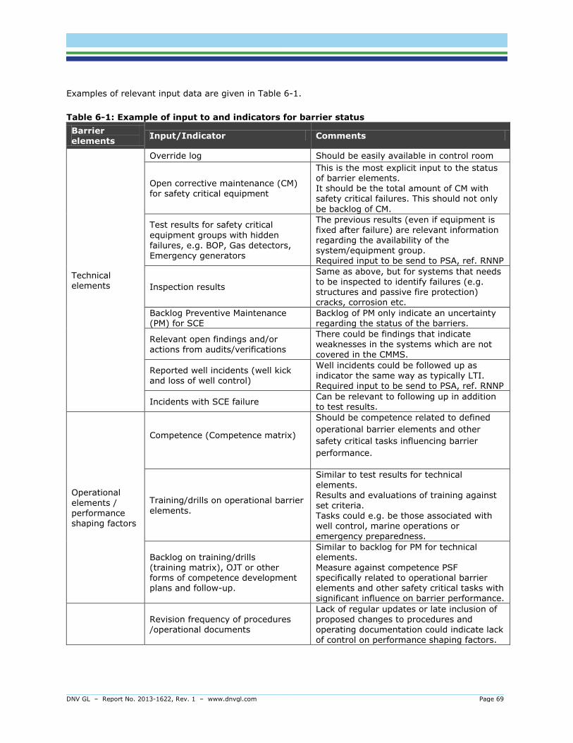
DNV GL – Report No. 2013-1622, Rev. 1 – www.dnvgl.com Page 69
Examples of relevant input data are given in Table 6-1.
Table 6-1: Example of input to and indicators for barrier status
Barrier elements
Input/Indicator Comments
Technical elements
Override log Should be easily available in control room
Open corrective maintenance (CM) for safety critical equipment
This is the most explicit input to the status of barrier elements. It should be the total amount of CM with safety critical failures. This should not only
be backlog of CM.
Test results for safety critical
equipment groups with hidden failures, e.g. BOP, Gas detectors, Emergency generators
The previous results (even if equipment is fixed after failure) are relevant information regarding the availability of the system/equipment group. Required input to be send to PSA, ref. RNNP
Inspection results
Same as above, but for systems that needs to be inspected to identify failures (e.g. structures and passive fire protection) cracks, corrosion etc.
Backlog Preventive Maintenance (PM) for SCE
Backlog of PM only indicate an uncertainty regarding the status of the barriers.
Relevant open findings and/or
actions from audits/verifications
There could be findings that indicate weaknesses in the systems which are not
covered in the CMMS.
Reported well incidents (well kick and loss of well control)
Well incidents could be followed up as indicator the same way as typically LTI. Required input to be send to PSA, ref. RNNP
Incidents with SCE failure Can be relevant to following up in addition to test results.
Operational
elements / performance shaping factors
Competence (Competence matrix)
Should be competence related to defined
operational barrier elements and other
safety critical tasks influencing barrier
performance.
Training/drills on operational barrier
elements.
Similar to test results for technical
elements. Results and evaluations of training against set criteria. Tasks could e.g. be those associated with well control, marine operations or emergency preparedness.
Backlog on training/drills (training matrix), OJT or other forms of competence development plans and follow-up.
Similar to backlog for PM for technical elements. Measure against competence PSF specifically related to operational barrier elements and other safety critical tasks with significant influence on barrier performance.
Revision frequency of procedures
/operational documents
Lack of regular updates or late inclusion of proposed changes to procedures and
operating documentation could indicate lack of control on performance shaping factors.

DNV GL – Report No. 2013-1622, Rev. 1 – www.dnvgl.com Page 70
Good practice 25 When choosing input/indicators to reflect the barrier status the operator should clarify the following:
- Do the input give relevant/important information about the status
- Is it possible to obtain the data or is it needed to improve/update e.g. systems to get the data
- Are the data reliable
- Are data retrievable
- Are the data available electronically, e.g. possible for automatic data gathering. If not, do
the operator has sufficient recourses to handle this manually
A success factor for information on test results is that personnel executing maintenance, training and
assurance activities report the results on a predefined format. “Test OK” is not a valuable information
when it comes to analysing the availability of a barrier. An good report of test can be; “pressure test of
BOP according to test program to 3200 psi. The result of test is 3200 psi and according to acceptance.”
Good practice 26 When reporting execution of test the following should be included:
- the result of test in duties
- the capacity or response
- if the test is according to acceptance.
6.2 Evaluate and communicate barrier status
If test results are available and acceptance criteria established the status of technical barrier elements
can be drawn from this. Since barrier functionality is fulfilled by technical operational elements
evaluating status of barriers will be more consistent based on a combination of:
- information about results of tests
- incident register
- information about quality of established processes and systems in place to control the risk like
maintenance, management of change, training etc.
Evaluation of barrier status can be done in several ways. It can be online generated based on
predefined algorithms and acceptance criteria or it can be assessed by safety systems domain experts
within the organisation.
Since information will have different format and come from different sources overview of all
information and evaluating the barrier status without a common presentation format can be difficult.
For easily access and a common overview a good solution can be to establish a barrier panel fit for
purpose.
A uniform methodology for describing status can be useful. This allows the organization to evaluate
and interpret the results in a consistent manner. One solution can be to introducing a rating system
with predefined tolerance criteria. Rating systems normally exists of colure coding with a general
description; see example in Table 6-2. In addition there should be some guidelines or criteria’s for the
different indicator, see examples in Table 6-3.

DNV GL – Report No. 2013-1622, Rev. 1 – www.dnvgl.com Page 71
Table 6-2: Example of rating system
Rating General description
Not functioning/not acceptable
Degraded or uncertain status
Good
More than three rating categories can be used if the operator wants a more detailed system, both
regarding evaluation and prioritizing for following up.
Table 6-3: Example of rating description for some indicators (ref. indicators in Table 6-1)
Open CM for SCE,
equipment level (or for the equipment group, but then an aggregation
system is needed)
Test result,
equipment group level (based on 12 last months)
Backlog PM,
equipment group +
Backlog on training/drills, per defined
training/drill activity
Training/ drills
Result, per defined training/drill activity
Etc.
CMMS code “dead” Above the acceptance criteria
NA Above the acceptance criteria
CMMS code “sick”
Failures, but below
the acceptance criteria
Backlog, i.e. uncertain status of the barriers
NA, or define if
relevant for particular training
No open CM No failures No backlog No failures
Based on the number of safety systems, equipment (total tags) and indicators this will generate a long
list of information. To easily give an overview it can be reasonable to do some kind of aggregation.
Different methods for aggregation can be applied, see examples in Table 6-4. Be aware that
aggregation introduces some challenges with respect to interpretation of the results. Examples of level
of visualization of results are given in Table 6-5.
Table 6-4: Example of possible methods that can be applied for aggregation.
Methodology Strengths Weaknesses Comments
Always show the worst rating at a lower level
Easy system to understand and implement
- With a lot of information it will “always” be
red. - Several yellows
can in some cased be worse than one/few reds.
With this system it is important to: - Always drill down to check
the amount at lower level - Communicate in the
organization that the total safety system not is red even if it show red, and can be weak even with yellow.
Aggregation rules, e.g. Green: at most 1 yellow, no red Yellow: at least 2 yellow (but not all) and at most 1 red
Red: 2 red or more,
or all yellow
Easy system to implement
Similar as above,
but at better solution regarding this weaknesses
Gives a “better picture” of the overview than the solution
above. However, the aggregation rules will never be “perfect” regarding given the right status at the system level.
Manual rating (except for the indicator level)
Gives relevant status information at the different
levels
Resource-demanding
If not using this method (or the method below) a similar evaluation can still be done when
evaluating the results:
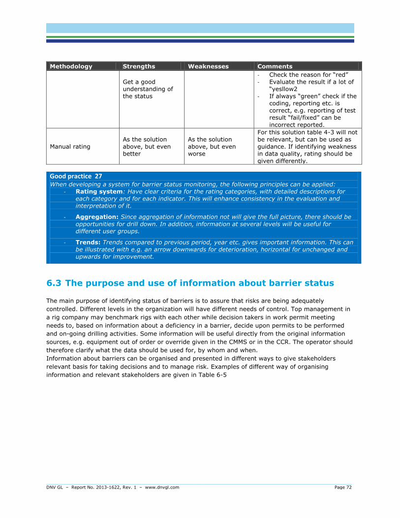
DNV GL – Report No. 2013-1622, Rev. 1 – www.dnvgl.com Page 72
Methodology Strengths Weaknesses Comments
Get a good understanding of the status
- Check the reason for “red” - Evaluate the result if a lot of
“yesllow2 - If always “green” check if the
coding, reporting etc. is correct, e.g. reporting of test result “fail/fixed” can be
incorrect reported.
Manual rating
As the solution
above, but even better
As the solution
above, but even worse
For this solution table 4-3 will not be relevant, but can be used as
guidance. If identifying weakness in data quality, rating should be
given differently.
Good practice 27 When developing a system for barrier status monitoring, the following principles can be applied:
- Rating system: Have clear criteria for the rating categories, with detailed descriptions for each category and for each indicator. This will enhance consistency in the evaluation and interpretation of it.
- Aggregation: Since aggregation of information not will give the full picture, there should be
opportunities for drill down. In addition, information at several levels will be useful for different user groups.
- Trends: Trends compared to previous period, year etc. gives important information. This can be illustrated with e.g. an arrow downwards for deterioration, horizontal for unchanged and upwards for improvement.
6.3 The purpose and use of information about barrier status
The main purpose of identifying status of barriers is to assure that risks are being adequately
controlled. Different levels in the organization will have different needs of control. Top management in
a rig company may benchmark rigs with each other while decision takers in work permit meeting
needs to, based on information about a deficiency in a barrier, decide upon permits to be performed
and on-going drilling activities. Some information will be useful directly from the original information
sources, e.g. equipment out of order or override given in the CMMS or in the CCR. The operator should
therefore clarify what the data should be used for, by whom and when.
Information about barriers can be organised and presented in different ways to give stakeholders
relevant basis for taking decisions and to manage risk. Examples of different way of organising
information and relevant stakeholders are given in Table 6-5

DNV GL – Report No. 2013-1622, Rev. 1 – www.dnvgl.com Page 73
Table 6-5: Example of different way of organising information and relevant stakeholders
Status level Stakeholders Comments
Per safety system (PS level)
Onshore management Offshore management
- Daily operation - Long term
Safety system responsible or Performance standard (PS) responsible *
This information can be used by managers to monitor the status of the barriers. Managers should regularly evaluate major accident risk and performance of the safety system for their offshore units. When evaluating the results they should decide if it is a need for temporary mitigating measures or some adjustments or
upgrades of the system(s). If used for daily operation, e.g. related to the work permits process, safe job analysis and drilling program, the information should be given per area.
* It is not required to have Performance Standards responsible, but it is a good solution to have dedicated persons responsible for the different PS’s who understand the system, has a continuous overview of the systems weakness and improvement potential.
Per equipment group
Onshore management
Offshore management - Daily opr. - Long term
When managers evaluates the results, it is important to not just following up with regular
maintenance (repair or replacement), but also identify if there is some repeating failures which indicate a need for decreased test interval, changing of components, upgrading of components/systems etc. The result of analysing the data can also lead to
increased test interval. In addition analysing data can also identify weaknesses in the tag structure, recording practise etc.
If used for daily operation, the information should be given per area.
This example of “status level” does not cover operational and organisational aspects.
Good practice 28 To ensure use of information regarding barrier status the operator should:
- identify and specify who and when it is going to be used (work processes).
- linked use to specific decision processes or arenas.
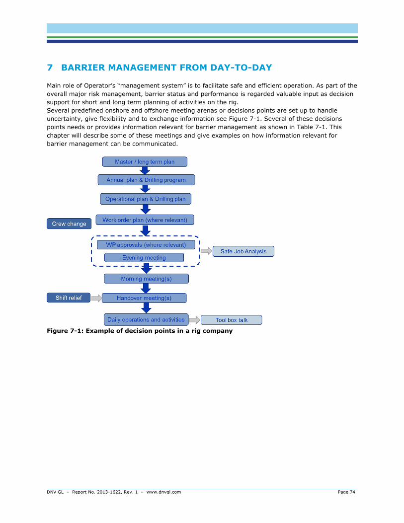
DNV GL – Report No. 2013-1622, Rev. 1 – www.dnvgl.com Page 74
7 BARRIER MANAGEMENT FROM DAY-TO-DAY
Main role of Operator’s “management system” is to facilitate safe and efficient operation. As part of the
overall major risk management, barrier status and performance is regarded valuable input as decision
support for short and long term planning of activities on the rig.
Several predefined onshore and offshore meeting arenas or decisions points are set up to handle
uncertainty, give flexibility and to exchange information see Figure 7-1. Several of these decisions
points needs or provides information relevant for barrier management as shown in Table 7-1. This
chapter will describe some of these meetings and give examples on how information relevant for
barrier management can be communicated.
Figure 7-1: Example of decision points in a rig company

DNV GL – Report No. 2013-1622, Rev. 1 – www.dnvgl.com Page 75
Table 7-1: Examples of how decisions points needs or provides information relevant for
barrier management
Decision point
When Who What Relevance for barrier management
Drill-well-on paper
Before start-up
and when needed
Company
OIM Driller
Identifies all risks and
obstacles in the next drilling sequence.
Needs to have an
overview of risk picture and status of barriers
WP approval/
Evening meeting
17 o’clock
Department
supervisors, OIM
Discuss and agree on all activities next day. Approves all work permits for next day.
Discuss any issues between drilling,
maintenance and other activities
Needs to have an overview of risk picture, status of barriers on an
area level, overrides and
isolations on safety systems. Decides measures to improve the barriers and compensating measures
SJA Before executing
Department workers
Risk management in activity
Needs to consider barriers that will be influenced by the job and barriers important for eliminating risk in the job
Issue WP 07 o’clock CCR Overview of all WP will be from CCR
Needs to have an overview of status of barriers on an area level
CCR Contentiously CCR Overview of all activity,
overrides, WP isolations
Needs to have an
overview of status of barriers on an area level
Gives input to overrides and isolations on safety systems
Activate WP
After 07 o’clock Area or system
responsible
Needs to have an overview of status of barriers on an area level
and override and isolation in area.
7.1 Work Permit (WP) approval
This meeting takes place in the evening before execution of work and relevant participants are: OIM,
Toolpusher and maintenance manager. The purpose of the meeting is to coordinate activities taking
place next day with regard to drilling, operation and maintenance. Some of these activities will be daily
routines not addressed by the work order system e.g. a routine check of lighting fixture, some
activities will be addressed by the work order system, e.g. preventive maintenance on the mud pump
and some of the work orders need to have a work permit.
The work permit system is based on the principle of internal control. This means that several
independent roles are involved in the approval, control, coordination and management of activities. On
a rig equipment and control of work activities is “owned” by operation/area/system responsibility while
required work to be performed is “supplied” by the respective executive department. In this way a WP
is considered a contract between two parties.
When deciding work and activities to be performed three questions are relevant to possess:
1. What need to be done to fulfilling requirements?
2. What cannot be done according to risk picture?
3. What can be done according to risk picture?

DNV GL – Report No. 2013-1622, Rev. 1 – www.dnvgl.com Page 76
When approving work orders barriers status should be known and also information about deficiency in
performance of the barriers should be used as basis for considering whether a work order can be
approved, or if an additional measure needs to be put in place. This information on an area level
together with the potential risk picture given deficiency in barriers will give valuable decision support
and be a good tool for communicating risk related to work orders and work permits.
The work permits are delivered from the CCR and the execution teams often do a toolbox talk before
start working. Area responsible or system responsible is the one activating the work permit. This role
coordinates all the work permits and work orders taking place in an area or on a system. This person is
a key resource when it comes to overview on activity and he must know the status on barriers in his
area, isolation valves, overrides and other information relevant for understanding the risk picture in
the area.
Good practice 29 When choosing input/indicators to reflect the barrier status the operator should clarify the following:
- Do the input give relevant/important information about the status
- Is it possible to obtain the data or is it needed to improve/update e.g. systems to get the data
- Are the data reliable
- Are data retrievable
- Are the data available electronically, e.g. possible for automatic data gathering. If not, do
the operator has sufficient recourses to handle this manually
7.2 Continuous improvement
Management of change (MoC) A process detailing method how changes shall be proposed, reviewed and approved for proper
implementation, giving full consideration to occupational -, major risk- and environmental concerns, operability and cost savings. Non- conformity Any state or condition that is not compliant with requirements, in this context this corresponds to any form of deviation, non-compliance.
If non-conformities are detected during activities related to operation, maintenance, assurance or
verification this should be handled in a non-conformity process. Results of a non-conformance process
can be temporary changes with an exemptions or permanent change. Permanent changes should be
handled in a management of change process.
Temporary and permanent changes and exemptions on safety systems should be traced and
communicated related to barrier status.
There might be situations where barriers are subject to modifications or alterations. This could be a
result of optimization, changes in design, operational conditions, or to fulfil new requirements. All
these issues need to be handled in a management of change process.
DNV GL – Report No. 2013-1622, Rev. 1 – www.dnvgl.com Page 77
Good practice 30 The performance standard shall reflect the current design and operation of the installation. In order to ensure this, the update of the PS should be a part of the MoC.
Comments: This implies that the PS should be a living and formal document which is updated when there is e.g.:
- Major modification on the installations design where new/updated company/regulatory requirements must be adhered to. Changes in production e.g.
- Higher/lower pressure, - Higher/lower temperatures,
- Composition (e.g. introduction of H2S in production)
- New knowledge, change the existing basic design basis - Changes in environmental conditions e.g. higher waves
7.3 Reporting and incident investigations
Rig companies have comprehensive reporting systems for unsafe conditions, near-misses and
incidents. In addition, incident investigations are carried out for more serious events. While the
majority of unsafe conditions and incidents reported are related to occupational safety, the systems
should be set up to capture major accident hazards and barriers. This is an important part of
continuous organizational learning beyond what is measured and followed up in verification and
assurance activities.
DNV GL – Report No. 2013-1622, Rev. 1 – www.dnvgl.com Page 78
Good practice 31 Ensure that systems for reporting and incident investigation are set up to capture the complexity of major accident hazards and barriers.
Comments: Contributions to major accident risk and barrier performance can be identified in the barrier analysis, barrier strategies, and performance standards. This includes, but is not limited to:
Hazards, hazardous events, and consequences (for areas) Barrier functions and barrier elements Barrier failures, including latent failures
Performance shaping factors
The reporting system should make it obvious to the user whether what is being reported affects barrier performance. Using the same terminology in the reporting systems and incident investigation secures learning across reporting systems and creates awareness about major accidents and barriers.
Much of what is reported would fall under the category of latent failures or performance shaping factors. For example, it should be possible to report procedures which contain errors or are past due for updates. Another example could be negative circumstances concerning testing or the condition of barrier elements, which may deserve attention beyond what is possible to achieve through other reporting systems (e.g. maintenance logs).
For organizational learning to be successful, some key principles apply: Personnel must be encouraged to report
Personnel must receive feedback on status of report (e.g. follow-up measures) Reports must not be used to sanction personnel It must be possible to perform statistical analysis and trending Improvement measures must to followed up to verify that they are correct and
implemented according to plan
Experience transfer between company stakeholders, e.g. between rigs and between the onshore and the offshore organization.

DNV GL – Report No. 2013-1622, Rev. 1 – www.dnvgl.com Page 79
8 KNOWLEDGE ABOUT BARRIER MANAGEMENT
Successful and sustainable implementation of barrier management in operations require a specific set
of competence (i.e. knowledge and skills) among personnel on different levels in the organization. The
management system and social interactions defines how competence is distributed in the organisation,
both onshore support and offshore.
This chapter suggest how competence distribution can be made (see Table 8-1)
Competence
Competence is about knowledge and skills.
- Knowledge is the theoretical understanding; how we know things
- Skills are the practical understanding; how we do things
Building competence involves some prior elements and stages;
- before we can understand we have to remember,
- before we can apply or do it we need to understand,
- before we can analyse we need to apply,
- before we can evaluate we have to be able to analyse,
These stages can be referred to as competence taxonomy. Different level in an organisation and
different situation in a value chain needs to possess different level of competence taxonomy when it
comes to risk e.g. the OIM needs to understand the full risk picture continuously while risk is managed
through the work permit system and the Safety Job Analysis for the mechanics doing preventive
maintenance on a mud pump.
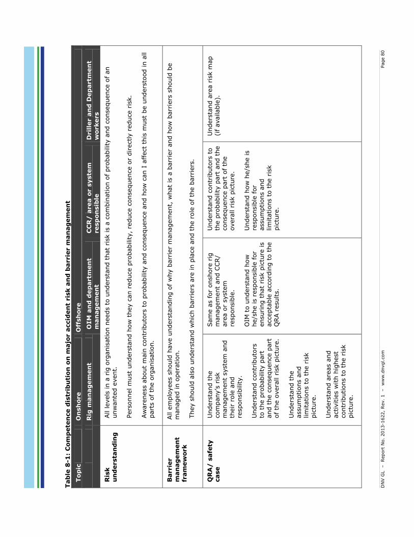
DN
V G
L
– Report
No.
2013-1
622,
Rev.
1 – w
ww
.dnvgl.com
Page 8
0
Tab
le 8
-1:
Com
pete
nce d
istr
ibu
tion
on
majo
r a
ccid
en
t ris
k a
nd
barrie
r m
an
ag
em
en
t
Top
ic
On
sh
ore
Off
sh
ore
R
ig m
an
ag
em
en
t O
IM
an
d d
ep
artm
en
t m
an
ag
em
en
t C
CR
/ a
rea o
r s
yste
m
resp
on
sib
le
Dril
ler a
nd
Dep
artm
en
t w
orkers
Ris
k
un
dersta
nd
ing
All levels
in a
rig
org
anis
ation n
eeds t
o u
nders
tand t
hat
risk is a
com
bin
ation o
f pro
bability a
nd c
onsequence o
f an
unw
ante
d e
vent.
Pers
onnel m
ust
unders
tand h
ow
they c
an r
educe p
robability,
reduce c
onsequence o
r dir
ectly r
educe r
isk.
Aw
are
ness a
bout
main
contr
ibuto
rs t
o p
robability a
nd c
onsequence a
nd h
ow
can I
affect
this
must
be u
nders
tood in a
ll
part
s o
f th
e o
rganis
ation.
Barrie
r
man
ag
em
en
t fr
am
ew
ork
All e
mplo
yees s
hould
have u
nders
tandin
g o
f w
hy b
arr
ier
managem
ent,
what
is a
barr
ier
and h
ow
barr
iers
should
be
managed in o
pera
tion.
They s
hould
als
o u
nders
tand w
hic
h b
arr
iers
are
in p
lace a
nd t
he r
ole
of th
e b
arr
iers
.
QR
A/
safe
ty
case
Unders
tand t
he
com
pany’s
ris
k
managem
ent
syste
m a
nd
their
role
and
responsib
ility.
Unders
tand c
ontr
ibuto
rs
to t
he p
robability p
art
and t
he c
onsequence p
art
of th
e o
vera
ll r
isk p
ictu
re.
U
nders
tand t
he
assum
ptions a
nd
lim
itations t
o t
he r
isk
pic
ture
.
Unders
tand a
reas a
nd
activitie
s w
ith h
ighest
contr
ibutions t
o t
he r
isk
pic
ture
.
Sam
e a
s for
onshore
rig
m
anagem
ent
and C
CR
/ are
a o
r syste
m
responsib
le.
OIM
to u
nders
tand h
ow
he/s
he is r
esponsib
le for
ensuri
ng t
hat
risk p
ictu
re is
accepta
ble
accord
ing t
o t
he
QRA r
esults.
Unders
tand c
ontr
ibuto
rs t
o
the p
robability p
art
and t
he
consequence p
art
of th
e
overa
ll r
isk p
ictu
re.
Unders
tand h
ow
he/s
he is
responsib
le for
assum
ptions a
nd
lim
itations t
o t
he r
isk
pic
ture
.
Unders
tand a
rea r
isk m
ap
(if available
).

DN
V G
L
– Report
No.
2013-1
622,
Rev.
1 – w
ww
.dnvgl.com
Page 8
1
Top
ic
On
sh
ore
Off
sh
ore
R
ig m
an
ag
em
en
t O
IM
an
d d
ep
artm
en
t m
an
ag
em
en
t C
CR
/ a
rea o
r s
yste
m
resp
on
sib
le
Dril
ler a
nd
Dep
artm
en
t w
orkers
Barrie
r
str
ate
gy
O
IM t
o u
nders
tand h
ow
he/s
he is r
esponsib
le for
ensuri
ng t
hat
the s
trate
gy
is follow
ed in o
pera
tions
and m
anagem
ent
of th
e r
ig.
Know
whic
h o
pera
tional
barr
ier
ele
ments
they a
re
responsib
le for.
Unders
tand t
he s
trate
gy
for
barr
iers
in p
lace t
o
handle
hazard
s in a
rea.
Know
whic
h o
pera
tional
barr
ier
ele
ments
they a
re
part
of perf
orm
ing.
Know
where
to locate
the
barr
ier
str
ate
gy
Know
that
the b
arr
ier
str
ate
gy c
onta
ins
info
rmation a
bout
hazard
s
and b
arr
iers
for
each a
rea.
Know
whic
h o
pera
tional
barr
ier
ele
ments
they a
re
part
of perf
orm
ing.
Perfo
rm
an
ce
sta
nd
ard
Know
how
to a
ppoin
t and
follow
up o
wners
or
perf
orm
ance s
tandard
s.
U
nders
tand h
ow
diffe
rent
pro
cesses influence
barr
ier
perf
orm
ance
requir
em
ents
.
Know
whic
h s
afe
ty s
yste
ms
(perf
orm
ance s
tandard
s)
they a
re r
esponsib
le for.
Know
the r
equir
em
ents
and t
he b
ackgro
und f
or
the
requir
em
ents
. Know
how
devia
tion fro
m
perf
orm
ance r
equir
em
ents
affects
ris
k p
ictu
re,
i.e.
how
barr
ier
failure
s a
nd
degra
dation in b
arr
ier
ele
ments
affect
barr
ier
functions.
U
nders
tand h
ow
to a
ssure
and v
eri
fy t
hat
perf
orm
ance r
equir
em
ents
are
met.
Know
and t
echnic
al
barr
iers
they a
re
responsib
le for.
Know
where
to fin
d
necessary
info
rmation a
nd
tools
(e.g
. pro
cedure
s)
for
carr
yin
g o
ut
task s
o t
hat
barr
ier
perf
orm
ance is
assure
d.
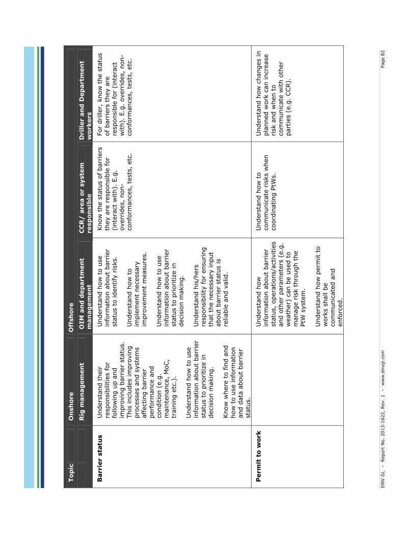
DN
V G
L
– Report
No.
2013-1
622,
Rev.
1 – w
ww
.dnvgl.com
Page 8
2
Top
ic
On
sh
ore
Off
sh
ore
R
ig m
an
ag
em
en
t O
IM
an
d d
ep
artm
en
t m
an
ag
em
en
t C
CR
/ a
rea o
r s
yste
m
resp
on
sib
le
Dril
ler a
nd
Dep
artm
en
t w
orkers
Barrie
r s
tatu
s
Unders
tand t
heir
re
sponsib
ilitie
s for
follow
ing u
p a
nd
impro
vin
g b
arr
ier
sta
tus.
This
inclu
des im
pro
vin
g
pro
cesses a
nd s
yste
ms
affecting b
arr
ier
perf
orm
ance a
nd
conditio
n (
e.g
. m
ain
tenance,
MoC,
train
ing e
tc.)
.
Unders
tand h
ow
to u
se
info
rmation a
bout
barr
ier
sta
tus t
o p
riori
tize in
decis
ion m
akin
g.
Know
where
to fin
d a
nd
how
to u
se info
rmation
and d
ata
about
barr
ier
sta
tus.
Unders
tand h
ow
to u
se
info
rmation a
bout
barr
ier
sta
tus t
o identify
ris
ks.
Unders
tand h
ow
to
imple
ment
necessary
im
pro
vem
ent
measure
s.
Unders
tand h
ow
to u
se
info
rmation a
bout
barr
ier
sta
tus t
o p
riori
tize in
decis
ion m
akin
g.
Unders
tand h
is/h
ers
re
sponsib
ility for
ensuri
ng
that
the n
ecessary
input
about
barr
ier
sta
tus is
reliable
and v
alid.
Know
the s
tatu
s o
f barr
iers
th
ey a
re r
esponsib
le for
(inte
ract
with).
E.g
. overr
ides,
non-
confo
rmances,
tests
, etc
.
For
dri
ller,
know
the s
tatu
s
of barr
iers
they a
re
responsib
le for
(inte
ract
with).
E.g
. overr
ides,
non-
confo
rmances,
tests
, etc
.
Perm
it t
o w
ork
U
nders
tand h
ow
in
form
ation a
bout
barr
ier
sta
tus,
opera
tions/a
ctivitie
s
and o
ther
para
mete
rs (
e.g
. w
eath
er)
can b
e u
sed t
o
manage r
isk t
hro
ugh t
he
PtW
syste
m.
Unders
tand h
ow
perm
it t
o
work
s s
hall b
e
com
munic
ate
d a
nd
enfo
rced.
Unders
tand h
ow
to
com
munic
ate
ris
ks w
hen
coord
inating P
tWs.
Unders
tand h
ow
changes in
pla
nned w
ork
can incre
ase
risk a
nd w
hen t
o
com
munic
ate
with o
ther
part
ies (
e.g
. CCR).
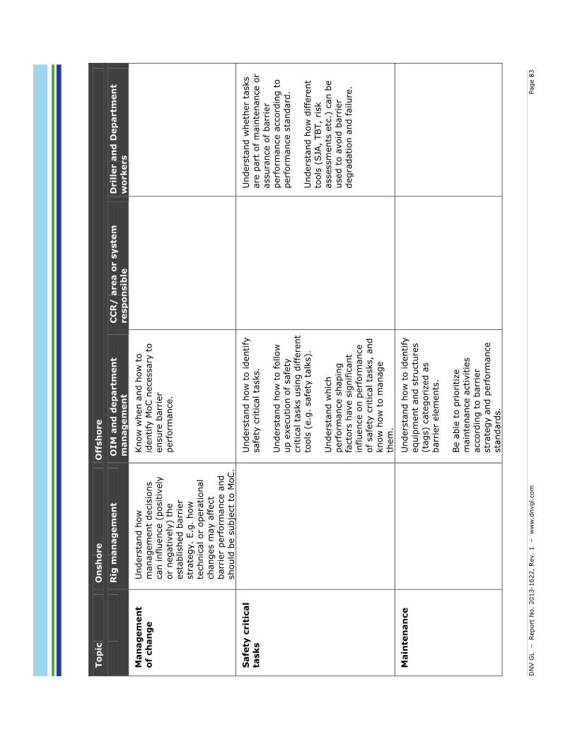
DN
V G
L
– Report
No.
2013-1
622,
Rev.
1 – w
ww
.dnvgl.com
Page 8
3
Top
ic
On
sh
ore
Off
sh
ore
R
ig m
an
ag
em
en
t O
IM
an
d d
ep
artm
en
t m
an
ag
em
en
t C
CR
/ a
rea o
r s
yste
m
resp
on
sib
le
Dril
ler a
nd
Dep
artm
en
t w
orkers
Man
ag
em
en
t of
ch
an
ge
Unders
tand h
ow
m
anagem
ent
decis
ions
can influence (
positiv
ely
or
negatively
) th
e
esta
blished b
arr
ier
str
ate
gy.
E.g
. how
te
chnic
al or
opera
tional
changes m
ay a
ffect
barr
ier
perf
orm
ance a
nd
should
be s
ubje
ct
to M
oC.
Know
when a
nd h
ow
to
identify
MoC n
ecessary
to
ensure
barr
ier
perf
orm
ance.
Safe
ty c
rit
ical
tasks
U
nders
tand h
ow
to identify
safe
ty c
ritical ta
sks.
Unders
tand h
ow
to follow
up e
xecution o
f safe
ty
cri
tical ta
sks u
sin
g d
iffe
rent
tools
(e.g
. safe
ty t
alk
s).
Unders
tand w
hic
h
perf
orm
ance s
hapin
g
facto
rs h
ave s
ignific
ant
influence o
n p
erf
orm
ance
of safe
ty c
ritical ta
sks,
and
know
how
to m
anage
them
.
U
nders
tand w
heth
er
tasks
are
part
of m
ain
tenance o
r assura
nce o
f barr
ier
perf
orm
ance a
ccord
ing t
o
perf
orm
ance s
tandard
.
Unders
tand h
ow
diffe
rent
tools
(SJA
, TBT,
risk
assessm
ents
etc
.) c
an b
e
used t
o a
void
barr
ier
degra
dation a
nd failure
.
Main
ten
an
ce
U
nders
tand h
ow
to identify
equip
ment
and s
tructu
res
(tags)
cate
gorized a
s
barr
ier
ele
ments
.
Be a
ble
to p
rioritize
main
tenance a
ctivitie
s
accord
ing t
o b
arr
ier
str
ate
gy a
nd p
erf
orm
ance
sta
ndard
s.
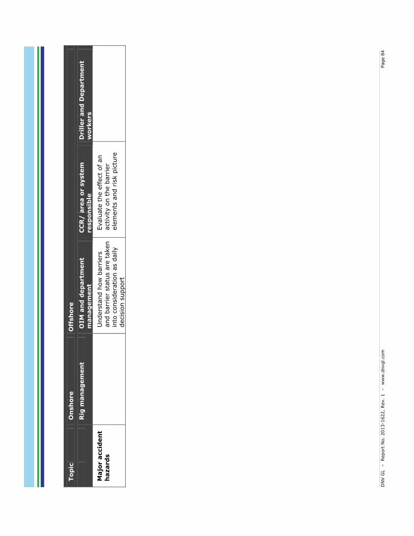
DN
V G
L
– Report
No.
2013-1
622,
Rev.
1 – w
ww
.dnvgl.com
Page 8
4
Top
ic
On
sh
ore
Off
sh
ore
R
ig m
an
ag
em
en
t O
IM
an
d d
ep
artm
en
t m
an
ag
em
en
t C
CR
/ a
rea o
r s
yste
m
resp
on
sib
le
Dril
ler a
nd
Dep
artm
en
t w
orkers
Majo
r a
ccid
en
t h
azard
s
U
nders
tand h
ow
barr
iers
and b
arr
ier
sta
tus a
re t
aken
into
consid
era
tion a
s d
aily
decis
ion s
upport
Evalu
ate
the e
ffect
of an
activity o
n t
he b
arr
ier
ele
ments
and r
isk p
ictu
re

DNV GL – Report No. 2013-1622, Rev. 1 – www.dnvgl.com Page 85
9 REFERENCES
/1/ HSE UK (2005). A guide to the offshore safety installations (Safety Case) regulations 2005: Guidance on regulations. ISBN 978 0 7176 6184 8.
/2/ ISO (1999). ISO 13702: Petroleum and natural gas industries – Control and mitigation of fires and explosions on offshore production platforms – Requirements and guidelines. Switzerland: International Organization for Standardization.
/3/ ISO GUIDE 73 (2009). Risk management – Vocabulary. Switzerland: International Organization for Standardization.
/4/ ISO (2009). ISO 31000: Risk management – Principles and guidelines. 1st Ed. Switzerland: International Organization for Standardization.
/5/ Kirwan, B., & Ainsworth, L.K. (1992). A guide to task analysis. Boca Raton, FL: Taylor & Francis
Group.
/6/ NORSOK (2013). NORSOK D-010: Well integrity in drilling and well operations. 4th Rev. Lysaker: Standards Norway.
/7/ NORSOK (2008). NORSOK S-001: Technical safety. 4th Ed. Lysaker: Standards Norway.
/8/ NORSOK (2011). NORSOK Z-008: Risk based maintenance and consequence classification. 3rd Ed. Lysaker: Standards Norway.
/9/ NORSOK (2010). NORSOK Z-013: Risk and emergency preparedness assessment. 3rd Ed. Lysaker: Standards Norway.
/10/ NS-EN (2010): NS-EN 13306: Maintenance and maintenance terminology. Lysaker: Standards Norway.
/11/ OGP (2012). Recommendations for enhancements to well control training, examination and certification. Report No. 476.
/12/ Petroleum Safety Authorities (2013). Prinsipper for barrierestyring i petroleumsvirksomheten.
www.ptil.no
/13/ Rausand, M. (2011). Risk assessment: Theory, methods, and applications. Hoboken, NJ: Wiley & Sons, Inc.
/14/ Reason, J. (1997). Managing the Risks of Organizational Accidents. Burlington: Ashgate Publishing Compay.
/15/ Skjerve, A.B.M, Rosness, R. Aase, K., & Bye, A. (2002). Mennesket som sikkerhetsbarriere i en
organisatorisk kontekst. IFE/HR/E-2003/023. IFE.
/16/ Step Change in Safety (unknown). Assurance & verification practitioner’s guide. www.stepchangeinsafety.net

DN
V G
L
– Report
No.
2013-1
622,
Rev.
1 – w
ww
.dnvgl.com
Page 8
6
AP
PE
ND
IX
A:
MA
PP
IN
G A
ND
EV
ALU
ATIO
N O
F P
ER
FO
RM
AN
CE S
HA
PIN
G F
AC
TO
RS
This
is a
fic
tive e
xam
ple
P
erf
orm
ance
Sh
apin
g Fa
cto
rs
PSF
map
pin
g an
d e
valu
atio
ns
Inp
ut
to P
SF r
equ
irem
en
ts
Ava
ilab
le T
ime
Ava
ilab
le t
ime
is d
efin
ed a
s th
e am
ou
nt
of
tim
e av
aila
ble
rel
ativ
e to
th
e ti
me
req
uir
ed t
o c
om
ple
te t
he
task
. D
uri
ng
a w
ell
con
tro
l eve
nt,
it
is
alw
ays
reco
mm
end
ed t
o d
ete
ct a
nd
sh
ut-
in t
he
we
ll as
so
on
as
po
ssib
le s
o t
hat
th
e vo
lum
e o
f in
flu
x, h
ence
SIC
P, i
s m
inim
ized
. If
the
we
ll is
sh
ut
in t
oo
lat
e ga
s m
ay r
each
th
e ri
ser
and
will
ris
e to
su
rfac
e w
her
e it
has
to
be
div
ert
ed.
It is
ho
wev
er,
no
t co
mm
on
to
sh
ut-
in t
he
we
ll w
ith
in a
def
ined
tim
e fr
ame
. Th
is d
epen
ds
on
ho
w q
uic
kly
the
infl
ux
is d
etec
ted
. N
ote
: R
ath
er t
han
def
inin
g a
req
uir
ed t
ime
to s
hu
t-in
a w
ell,
dri
llers
are
gi
ven
th
e ad
vice
or
auth
ori
ty t
o s
hu
t-in
th
e w
ell w
hen
un
sure
. A
fter
h
avin
g sh
ut
in t
he
wel
l th
e d
rille
r h
as a
cer
tain
tim
e av
aila
ble
to
ci
rcu
late
ou
t th
e ki
ck b
efo
re g
as r
ises
to
lev
els
wh
ere
incr
ease
d
pre
ssu
res
may
dam
age
the
wel
l in
tegr
ity.
Th
is d
epen
ds
on
th
e si
ze
of
the
infl
ux,
fo
rmat
ion
/we
ll in
tegr
ity,
wel
l d
epth
, am
on
g o
ther
p
aram
ete
rs.
The
dri
ller
mu
st b
e tr
ain
ed i
n e
arly
kic
k d
ete
ctio
n a
nd
saf
e ci
rcu
lati
on
of
the
we
ll.
This
in
clu
des
in
terp
reta
tio
n
of
kick
in
dic
ato
rs,
corr
ect
use
o
f p
roce
du
res,
an
d
op
erat
ion
o
f co
ntr
ols
.
Stre
ss /
St
ress
ors
St
ress
u
sed
in
th
e co
nte
xt o
f a
we
ll co
ntr
ol
situ
atio
n
refe
rs
to
un
des
irab
le c
on
dit
ion
s an
d f
acto
rs t
hat
hav
e d
etri
men
tal
effe
cts
on
th
e d
rille
r’smonitoringan
dd
ecisionm
akingprocess,whichm
ay
resu
lt in
inco
rrec
t ac
tio
ns.
Stre
ss c
an b
e d
ue
to t
he
follo
win
g fa
cto
rs:
Co
mp
eten
ce &
Exp
erie
nce
;
Man
agem
ent
Cu
ltu
re;
Co
mp
eten
ce &
Exp
erie
nce
1.
A d
rille
r w
ork
ing
in a
n e
con
om
ical
ly o
rien
ted
(as
op
po
sed
to
saf
ety
ori
ente
d)
envi
ron
men
t w
ill b
e ex
po
sed
to
hig
her
st
ress
wh
en h
e d
ecid
es t
o s
hu
t-in
th
e w
ell.
Un
der
th
ese
circ
um
stan
ces,
p
ress
ure
s fr
om
m
anag
emen
t w
ill
be
det
rim
enta
l tothe
drilling’sjudgm
entofthe
situation.
Incr
ease
d c
om
pet
en
ce o
f th
e d
rille
r w
ill b
e cr
itic
al d
uri
ng
inte
rpre
tati
on
of
real
tim
e d
rilli
ng
par
amet
ers
an
d f
low
ch
eck
resu
lts
un
der
th
ese
situ
atio
ns
(In
terd
epen
den
ce
with“Experience/Training”PSF).Second
ly,
pro
mo
tin
g a
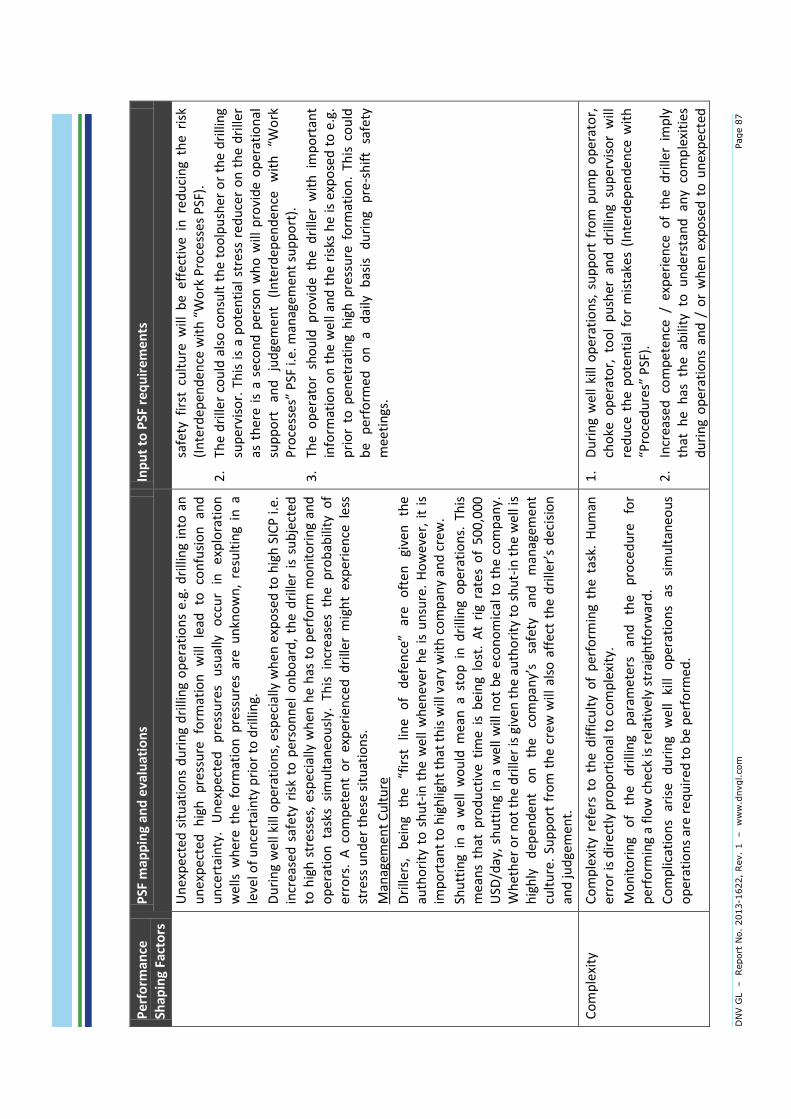
DN
V G
L
– Report
No.
2013-1
622,
Rev.
1 – w
ww
.dnvgl.com
Page 8
7
Pe
rfo
rman
ce
Shap
ing
Fact
ors
P
SF m
app
ing
and
eva
luat
ion
s In
pu
t to
PSF
req
uir
eme
nts
Un
exp
ecte
d s
itu
atio
ns
du
rin
g d
rilli
ng
op
erat
ion
s e.
g. d
rilli
ng
into
an
u
nex
pec
ted
h
igh
p
ress
ure
fo
rmat
ion
w
ill
lead
to
co
nfu
sio
n
and
u
nce
rtai
nty
. U
nex
pec
ted
p
ress
ure
s u
sual
ly
occ
ur
in
exp
lora
tio
n
we
lls w
her
e th
e fo
rmat
ion
pre
ssu
res
are
un
kno
wn
, re
sult
ing
in a
le
vel o
f u
nce
rtai
nty
pri
or
to d
rilli
ng.
Du
rin
g w
ell
kill
op
erat
ion
s, e
spec
ially
wh
en e
xpo
sed
to
hig
h S
ICP
i.e.
in
crea
sed
saf
ety
risk
to
per
son
nel
on
bo
ard
, th
e d
rille
r is
su
bje
cted
to
hig
h s
tres
ses,
esp
ecia
lly w
hen
he
has
to
per
form
mo
nit
ori
ng
and
o
per
atio
n t
asks
sim
ult
aneo
usl
y. T
his
in
crea
ses
the
pro
bab
ility
of
erro
rs.
A c
om
pet
ent
or
exp
erie
nce
d d
rille
r m
igh
t ex
per
ien
ce l
ess
stre
ss u
nd
er t
hes
e si
tuat
ion
s.
Man
agem
ent
Cu
ltu
re
Drille
rs,being
the
“firstlin
eofdefence”
are
oftengiventhe
auth
ori
ty t
o s
hu
t-in
th
e w
ell
wh
enev
er h
e is
un
sure
. H
ow
ever
, it
is
imp
ort
ant
to h
igh
ligh
t th
at t
his
will
var
y w
ith
co
mp
any
and
cre
w.
Shu
ttin
g in
a w
ell
wo
uld
mea
n a
sto
p i
n d
rilli
ng
op
erat
ion
s. T
his
m
ean
s th
at p
rod
uct
ive
tim
e is
bei
ng
lost
. A
t ri
g ra
tes
of
50
0,0
00
U
SD/d
ay,
shu
ttin
g in
a w
ell
will
no
t b
e ec
on
om
ical
to
th
e co
mp
any.
W
het
her
or
no
t th
e d
rille
r is
giv
en
th
e au
tho
rity
to
sh
ut-
in t
he
wel
l is
highlydep
enden
tonthe
compan
y’s
safetyan
dman
agem
ent
culture.Su
pportfromthecrew
willalsoaffectthedrille
r’sdec
isio
n
and
jud
gem
ent.
safe
ty f
irst
cu
ltu
re w
ill b
e ef
fect
ive
in r
edu
cin
g th
e ri
sk
(Interdep
enden
cewith“WorkProcessesPSF).
2.
The
dri
ller
cou
ld a
lso
co
nsu
lt t
he
too
lpu
sher
or
the
dri
llin
g su
per
viso
r. T
his
is
a p
ote
nti
al s
tre
ss r
edu
cer
on
th
e d
rille
r as
th
ere
is a
sec
on
d p
erso
n w
ho
will
pro
vid
e o
per
atio
nal
supportan
djudge
men
t(Interdep
enden
cewith“W
ork
Processes”PSFi.e.m
anagem
entsupport).
3.
The
op
erat
or
sho
uld
pro
vid
e th
e d
rille
r w
ith
im
po
rtan
t in
form
atio
n o
n t
he
we
ll an
d t
he
risk
s h
e is
exp
ose
d t
o e
.g.
pri
or
to p
enet
rati
ng
hig
h p
ress
ure
fo
rmat
ion
. Th
is c
ou
ld
be
per
form
ed
on
a
dai
ly
bas
is
du
rin
g p
re-s
hif
t sa
fety
m
eeti
ngs
.
Co
mp
lexi
ty
Co
mp
lexi
ty r
efer
s to
th
e d
iffi
cult
y o
f p
erfo
rmin
g th
e ta
sk.
Hu
man
er
ror
is d
irec
tly
pro
po
rtio
nal
to
co
mp
lexi
ty.
Mo
nit
ori
ng
of
the
dri
llin
g p
aram
ete
rs
and
th
e p
roce
du
re
for
per
form
ing
a fl
ow
ch
eck
is r
elat
ivel
y st
raig
htf
orw
ard
.
Co
mp
licat
ion
s ar
ise
du
rin
g w
ell
kill
op
erat
ion
s as
si
mu
ltan
eou
s o
per
atio
ns
are
req
uir
ed t
o b
e p
erfo
rmed
.
1.
Du
rin
g w
ell
kill
op
erat
ion
s, s
up
po
rt f
rom
pu
mp
op
erat
or,
ch
oke
op
erat
or,
to
ol
pu
sher
an
d d
rilli
ng
sup
ervi
sor
will
re
du
ce t
he
po
ten
tial
fo
r m
ista
kes
(In
terd
epen
den
ce w
ith
“Procedures”PSF).
2.
Incr
ease
d c
om
pet
ence
/ e
xper
ien
ce o
f th
e d
rille
r im
ply
th
at h
e h
as t
he
abili
ty t
o u
nd
erst
and
an
y co
mp
lexi
ties
d
uri
ng
op
erat
ion
s an
d /
or
wh
en e
xpo
sed
to
un
exp
ecte
d
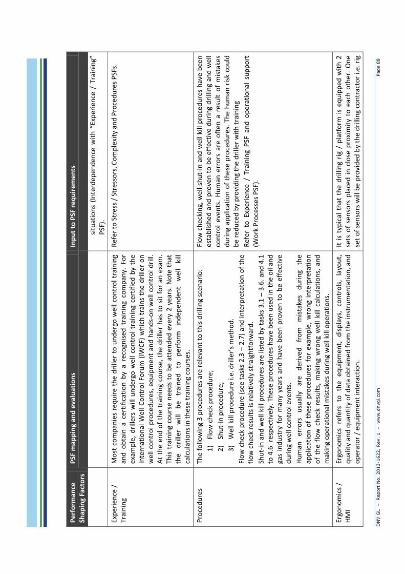
DN
V G
L
– Report
No.
2013-1
622,
Rev.
1 – w
ww
.dnvgl.com
Page 8
8
Pe
rfo
rman
ce
Shap
ing
Fact
ors
P
SF m
app
ing
and
eva
luat
ion
s In
pu
t to
PSF
req
uir
eme
nts
situations(Interdep
enden
cew
ith“Experience/Training”
PSF
).
Exp
erie
nce
/
Trai
nin
g M
ost
co
mp
anie
s re
qu
ire
the
dri
ller
to u
nd
ergo
we
ll co
ntr
ol
trai
nin
g an
d o
bta
in a
cer
tifi
cati
on
by
a re
cogn
ised
tra
inin
g co
mp
any.
Fo
r ex
amp
le,
dri
llers
will
un
der
go w
ell
con
tro
l tr
ain
ing
cert
ifie
d b
y th
e In
tern
atio
nal
Wel
l C
on
tro
l Fo
rum
(IW
CF)
wh
ich
tra
ins
the
dri
ller
on
w
ell
con
tro
l p
roce
du
res,
eq
uip
men
t an
d h
and
s-o
n w
ell
con
tro
l dri
ll.
At
the
end
of
the
trai
nin
g co
urs
e, t
he
dri
ller
has
to
sit
fo
r an
exa
m.
This
tra
inin
g co
urs
e n
eed
s to
be
atte
nd
ed e
very
2 y
ears
. N
ote
th
at
the
dri
ller
will
b
e tr
ain
ed
to
per
form
in
dep
end
ent
we
ll ki
ll ca
lcu
lati
on
s in
th
ese
trai
nin
g co
urs
es.
Ref
er
to S
tres
s /
Stre
sso
rs, C
om
ple
xity
an
d P
roce
du
res
PSF
s.
Pro
ced
ure
s Th
e fo
llow
ing
3 p
roce
du
res
are
rele
van
t to
th
is d
rilli
ng
scen
ario
:
1)
Flo
w c
hec
k p
roce
du
re;
2)
Shu
t-in
pro
ced
ure
;
3)
Wellkillprocedurei.e.driller’smethod.
Flo
w c
hec
k p
roce
du
re (
see
task
s 2
.3 –
2.7
) an
d in
terp
reta
tio
n o
f th
e fl
ow
ch
eck
resu
lts
is r
elat
ivel
y st
raig
htf
orw
ard
.
Shu
t-in
an
d w
ell
kill
pro
ced
ure
s ar
e lis
ted
by
task
s 3
.1 –
3.6
. an
d 4
.1
to 4
.6.
resp
ecti
vely
. Th
ese
pro
ced
ure
s h
ave
bee
n u
sed
in t
he
oil
and
ga
s in
du
stry
fo
r m
any
year
s an
d h
ave
bee
n p
rove
n t
o b
e ef
fect
ive
du
rin
g w
ell c
on
tro
l eve
nts
.
Hu
man
er
rors
u
sual
ly
are
der
ived
fr
om
m
ista
kes
du
rin
g th
e ap
plic
atio
n o
f th
ese
pro
ced
ure
s fo
r ex
amp
le,
wro
ng
inte
rpre
tati
on
o
f th
e fl
ow
ch
eck
resu
lts,
mak
ing
wro
ng
we
ll ki
ll ca
lcu
lati
on
s, a
nd
m
akin
g o
per
atio
nal
mis
take
s d
uri
ng
wel
l kill
op
erat
ion
s.
Flo
w c
hec
kin
g, w
ell s
hu
t-in
an
d w
ell
kill
pro
ced
ure
s h
ave
bee
n
esta
blis
hed
an
d p
rove
n t
o b
e ef
fect
ive
du
rin
g d
rilli
ng
and
we
ll co
ntr
ol
even
ts.
Hu
man
err
ors
are
oft
en
a r
esu
lt o
f m
ista
kes
du
rin
g ap
plic
atio
n o
f th
ese
pro
ced
ure
s. T
he
hu
man
ris
k co
uld
b
e re
du
ced
by
pro
vid
ing
the
dri
ller
wit
h t
rain
ing
Ref
er
to E
xper
ien
ce /
Tra
inin
g P
SF a
nd
op
erat
ion
al s
up
po
rt
(Wo
rk P
roce
sses
PSF
).
Ergo
no
mic
s /
HM
I Er
gon
om
ics
refe
rs
to
the
equ
ipm
ent,
d
isp
lays
, co
ntr
ols
, la
you
t,
qu
alit
y an
d q
uan
tity
of
dat
a o
bta
ined
fro
m t
he
inst
rum
enta
tio
n, a
nd
o
per
ato
r /
equ
ipm
ent
inte
ract
ion
.
It i
s ty
pic
al t
hat
th
e d
rilli
ng
rig
/ p
latf
orm
is
equ
ipp
ed w
ith
2
sets
of
sen
sors
pla
ced
in
clo
se p
roxi
mit
y to
eac
h o
ther
. O
ne
set
of
sen
sors
will
be
pro
vid
ed b
y th
e d
rilli
ng
con
trac
tor
i.e.
rig
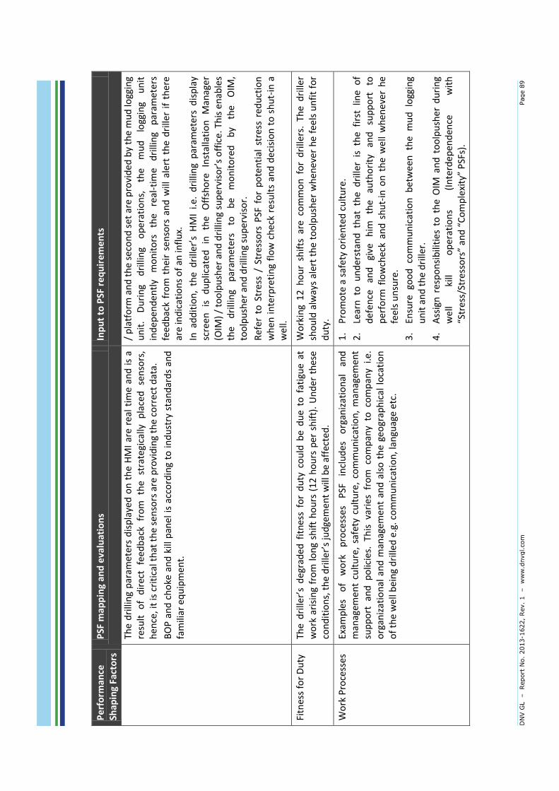
DN
V G
L
– Report
No.
2013-1
622,
Rev.
1 – w
ww
.dnvgl.com
Page 8
9
Pe
rfo
rman
ce
Shap
ing
Fact
ors
P
SF m
app
ing
and
eva
luat
ion
s In
pu
t to
PSF
req
uir
eme
nts
The
dri
llin
g p
aram
eter
s d
isp
laye
d o
n t
he
HM
I ar
e re
al t
ime
and
is
a re
sult
o
f d
irec
t fe
ed
bac
k fr
om
th
e st
rate
gica
lly
pla
ced
se
nso
rs,
hen
ce, i
t is
cri
tica
l th
at t
he
sen
sors
are
pro
vid
ing
the
corr
ect
dat
a.
BO
P a
nd
ch
oke
an
d k
ill p
anel
is
acco
rdin
g to
in
du
stry
sta
nd
ard
s an
d
fam
iliar
eq
uip
men
t.
/ p
latf
orm
an
d t
he
seco
nd
set
are
pro
vid
ed b
y th
e m
ud
logg
ing
un
it.
Du
rin
g d
rilli
ng
op
erat
ion
s,
the
mu
d
logg
ing
un
it
ind
epen
den
tly
mo
nit
ors
th
e re
al-t
ime
dri
llin
g p
aram
ete
rs
fee
db
ack
fro
m t
hei
r se
nso
rs a
nd
will
ale
rt t
he
dri
ller
if t
her
e ar
e in
dic
atio
ns
of
an in
flu
x.
Inaddition,thedriller’sHMIi.e
.drillingparam
etersdisplay
scre
en
is
d
up
licat
ed
in
th
e O
ffsh
ore
In
stal
lati
on
M
anag
er
(OIM
)/toolpusheranddrillingsupervisor’soffice.Thisenab
les
the
dri
llin
g p
aram
eter
s to
b
e m
on
ito
red
b
y th
e O
IM,
too
lpu
sher
an
d d
rilli
ng
sup
ervi
sor.
Ref
er
to S
tres
s /
Stre
sso
rs P
SF f
or
po
ten
tial
str
ess
red
uct
ion
w
hen
in
terp
reti
ng
flo
w c
hec
k re
sult
s an
d d
ecis
ion
to
sh
ut-
in a
w
ell.
Fitn
ess
for
Du
ty
Thedrille
r’sdeg
raded
fitnessfordutycouldbeduetofatigueat
wo
rk a
risi
ng
fro
m l
on
g sh
ift
ho
urs
(1
2 h
ou
rs p
er s
hif
t).
Un
der
th
ese
conditions,thedrille
r’sjudge
men
twillbeaffected.
Wo
rkin
g 1
2 h
ou
r sh
ifts
are
co
mm
on
fo
r d
rille
rs.
The
dri
ller
sho
uld
alw
ays
aler
t th
e to
olp
ush
er w
hen
ever
he
fee
ls u
nfi
t fo
r d
uty
.
Wo
rk P
roce
sses
Ex
amp
les
of
wo
rk
pro
cess
es
PSF
in
clu
des
o
rgan
izat
ion
al
and
m
anag
emen
t cu
ltu
re,
safe
ty c
ult
ure
, co
mm
un
icat
ion
, m
anag
emen
t su
pp
ort
an
d p
olic
ies.
Th
is v
arie
s fr
om
co
mp
any
to c
om
pan
y i.e
. o
rgan
izat
ion
al a
nd
man
agem
ent
and
als
o t
he
geo
grap
hic
al l
oca
tio
n
of
the
wel
l bei
ng
dri
lled
e.g
. co
mm
un
icat
ion
, lan
guag
e e
tc.
1.
Pro
mo
te a
saf
ety
ori
ente
d c
ult
ure
.
2.
Lear
n t
o u
nd
erst
and
th
at t
he
dri
ller
is t
he
firs
t lin
e o
f d
efe
nce
an
d
give
h
im
the
auth
ori
ty
and
su
pp
ort
to
p
erfo
rm f
low
chec
k an
d s
hu
t-in
on
th
e w
ell
wh
enev
er h
e fe
els
un
sure
.
3.
Ensu
re
goo
d c
om
mu
nic
atio
n b
etw
een
th
e m
ud
lo
ggin
g u
nit
an
d t
he
dri
ller.
4.
Ass
ign
res
po
nsi
bili
ties
to
th
e O
IM a
nd
to
olp
ush
er d
uri
ng
we
ll ki
ll o
per
atio
ns
(In
terd
epen
den
ce
wit
h
“Stress/Stressors”an
d“Complexity”PSFs).


DNV GL – Report No. 2013-1622, Rev. 1 – www.dnvgl.com Page 90
ABOUT DNV GL Driven by our purpose of safeguarding life, property and the environment, DNV GL enables organizations to advance the safety and sustainability of their business. We provide classification and technical assurance along with software and independent expert advisory services to the maritime, oil and gas, and energy industries. We also provide certification services to customers across a wide range of
industries. Operating in more than 100 countries, our 16,000 professionals are dedicated to helping our customers make the world safer, smarter and greener.


