Manual No. 00201 February 2009 WARNING: Before operating this lift, read and understand this operator’s manual. Become familiar with the potential hazards associated with the operation of this crane. Contact EZ Rig Cranes, Inc. if you have any questions regarding the use of EZ Rig® Cranes. Operator’s Manual A-1 Series EZ Rig® Crane EZ Rig Crane • P.O. Box 3009 Ventura, Ca 93006-3009 • Phone: 844-395-4387 • Website: www.EZRigCrane.com
Transcript
Manual No. 00201 February 2009
WARNING:Before operating this lift, read
and understand this operator’s manual.Become familiar with the potential
hazards associated with the operationof this crane.
Contact EZ Rig Cranes, Inc. ifyou have any questions regarding the
use of EZ Rig® Cranes.
Operator’s ManualA-1 Series EZ Rig® Crane
EZ Rig Crane • P.O. Box 3009 Ventura, Ca 93006-3009 • Phone: 844-395-4387 • Website: www.EZRigCrane.com
Disassembly and Assembly Instructions…………………………………………..7
Parts Identification…………………………………………………………………9
Parts List……………………………………………………………………………10
Maintenance………………………………………………………………………..11
Contacting us……………………………………………………………………….12
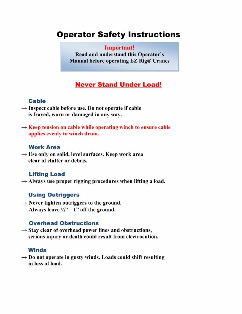
Operator Safety Instructions
Never Stand Under Load!
Cable→ Inspect cable before use. Do not operate if cable is frayed, worn or damaged in any way.
→ Keep tension on cable while operating winch to ensure cable applies evenly to winch drum.
Work Area→ Use only on solid, level surfaces. Keep work area clear of clutter or debris.
Lifting Load→ Always use proper rigging procedures when lifting a load. Using Outriggers→ Never tighten outriggers to the ground. Always leave ½” – 1” off the ground.
Overhead Obstructions→ Stay clear of overhead power lines and obstructions, serious injury or death could result from electrocution.
Winds→ Do not operate in gusty winds. Loads could shift resulting in loss of load.
Important!Read and understand this Operator’s
Manual before operating EZ Rig® Cranes
Operator’s Safety Instructions(continued)
Attendance→ Never leave EZ Rig® Crane unattended with an elevated load.
Side Load→ Do not climb on EZ Rig® Crane or put side load, such as ladders on mast.
Weather→ Do not operate during storms, electrocution could result from lighting strikes and wet surfaces could cause EZ Rig® Crane to shift, resulting in injury or death.
Load Pulling→ Do not pull or drag load without crane secured to solid object. Do not move EZ
Rig® Crane by pulling load line.
Replacement Parts→ Never use parts or accessories with EZ Rig® Cranes that are not supplied by the manufacturer. Contact EZ Rig Cranes, Inc. for replacement parts (refer to parts list for part #).
Proper Attire→ Always wear proper work clothing. Hard hat, safety shoes, and gloves should be worn as a precaution while operating this lift.
Bystanders→ Avoid horseplay around equipment and keep bystanders at a safe distance while in use. Do not allow children to operate this unit and always keep them out of work areas.
Mast: (floor to top of winch w/ boom at horizontal)
5’-4”
Base: Leg Length:
Closed - 8’-0” Ext. 1 - 9’-0½” Ext. 2 - 10’-0½”
Base Width:
Closed - 2’-10” Open - 6’- 0”
Weight: (w/ counterweight attachment)
1050lbs.
Specifications(Weight Capacity)
→ Always use counterweight system when lifting a load beyond the length of the legs, such as over the edge of a building or an obstruction.
→ Always use snatch block attachment when lifting loads in excess of 1,000 lbs.
Warning!Lifting more than the recommended load
limit can cause serious personal injury and even death.
EZ Rig Crane assembly and disassembly instructions
*EZ Rig Cranes are designed to be disassembled and reassembled at any time and it has no adverse effects on either the product warranty or crane certification. Below are the basic instructions for the safe and timely disassembly and reassembly of the crane.
Disassembly
*Always be cautious of pinch points!
Always utilize a minimum of two (2) employees for safe assembly/disassembly.
1) Removing inner boom:- Important - secure cable to winch drum (with tape or similar) to prevent unraveling.
- Remove bolt at end of inner boom, allowing removal of cable from sheave.- Remove ½” boom adjustment pin, allowing inner boom to slide out of outer boom.
2) Removing outer boom: -Supporting end of boom, remove upper jack bolt. - Remove 1” main boom pin to remove outer boom (removal of winch is optional
for weight reduction by unbolting from top of outer boom, noting location of flat washers for reassembly).
-Put outriggers down to reduce weight on front caster wheels.-Slide inner legs out of outer legs while pulling out on snap pins located on inside of outer legs.
5) Leaving outriggers down, remove spreader bar, 5/8” leg adjustment pins and ¾” hinge bolts allowing removal of front legs from back legs. (pry bar may be required to separate)
6) Tilt mast all the way back onto floor, leaving rear legs vertical. (Do not remove 5/8” leg adjustment pins and 7/8” hinge bolts until step 9).
7) Remove 5/8” leg adjustment pins and 7/8” bolts to remove rear legs from base of mast.
*Caution – mast weight approx. 175 lbs.!
Replace bolts, pins and nuts during disassembly to ensure proper reassembly
Assembly
*Always be cautious of pinch points!
(For reassembly, repeat disassembly steps in opposite order)
1) Position mast flat on the floor with hinges facing up.2) Replace outriggers on rear legs. (ensuring that the legs are on the correct side by
direction of outriggers)3) Assemble rear legs with 7/8” hinge bolts first and 5/8” leg adjustment pins last.
(Snap pins should be on the inside of each leg).Important - when tightening7/8” hinge bolts, tighten fully and back off ½ turn to allow for hinge action.*Inspect hinge faces for proper lubrication. Lubricate with white lithiumgrease if needed.
4) Tilt mast upright, allowing outriggers to support mast weight.5) Assemble front legs with ¾” bolts and 5/8” leg adjustment pins and insert spreader
bar.Important - when tightening ¾” hinge bolts, tighten fully and back off ½ turn to allow for hinge action.
6) Insert inner legs into outer legs by pulling out on snap pins located on the inside of outer legs.
7) Attach outer boom to mast with 1” boom pin.8) Attach hydraulic jack to mast and outer boom while supporting the end of the
boom.9) With hydraulic jack attached, insert inner boom and ½” boom adjustment pin to
lock.- If winch was removed from outer boom during assembly, attach winch noting the proper location of washers upon disassembly.
10) Remove cable guide bolt at end of boom to allow cable placement on sheave.11) Replace cable guide bolt12) Remove (tape or similar) from winch drum used to keep cable from unraveling.
*Check all bolts, pins and hinges for proper location and operation before use!
*See pictures below for parts identification
Inner boom and Sheave
Snatch block
Outer Boom
WinchHydraulic jack
Counterweights
Outriggers
Spreader bar
Mast
Rear hinge
Front hinge
Parts List
1 Grade 8 Hitch Pin 1" x 6" 106.24 Grade 8 Hitch Pin 1/2" x 2" 106.31 Grade 8 Hitch Pin 1/2" x 4" 106.41 GOLO Power Winch 12-15 RMO1 8 Ton Hydraulic Crane Jack 1021 1 Ton Latch kit for hook 4X4051 Sheeve M405A130 ft. 130 ft. 1/4'' Aircraft Cable 1044 8" Casters PR820S
Nuts and Bolts2 Grade 8 Bolt 7/8" x 8" 106.52 Grade 8 Nylock Nut 7/8" 106.62 Grade 8 Bolt 3/4" x 7" 106.74 Grade 8 Nylock Nut 3/4" 106.816 Grade 8 Bolt 3/8" x 1-1/2" 106.917 Grade 8 Nylock Nut 3/8" 106.1a4 Grade 8 Bolt 1/2" x 2-1/4" 106.2a2 Grade 8 Bolt 3/4" x 4" 106.3a1 Grade 8 Stainless Bolt 3/8" x 3/4" 106.4a1 Standard 3/8" Nut 106.5a1 Grade 8 Bolt 3/8" x 2-1/2" 106.6a1 Grade 8 Bolt 5/8" x 3-3/4" 106.8a1 Grade 8 Nut 5/8" 106.9a
Contact EZ Rig cranes, Inc. for replacement parts! Using alternative, non tested parts can cause serious injury or death and void your
product warranty.
Maintenance
→ Regularly inspect cable for damages. Replace if frayed, cut or damaged in any way.
→ Regularly inspect cable clamps (bolts that connect hook to cable) for proper tightness.
→ Apply heavy duty bearing grease to base hinges and cable sheave when necessary.
→ If hydraulic jack bleeds off under load, hydraulic fluid may need to be added to jack. (see jack manual supplied)
Regular lubrication of base hinges reduces friction and increases ease of use.