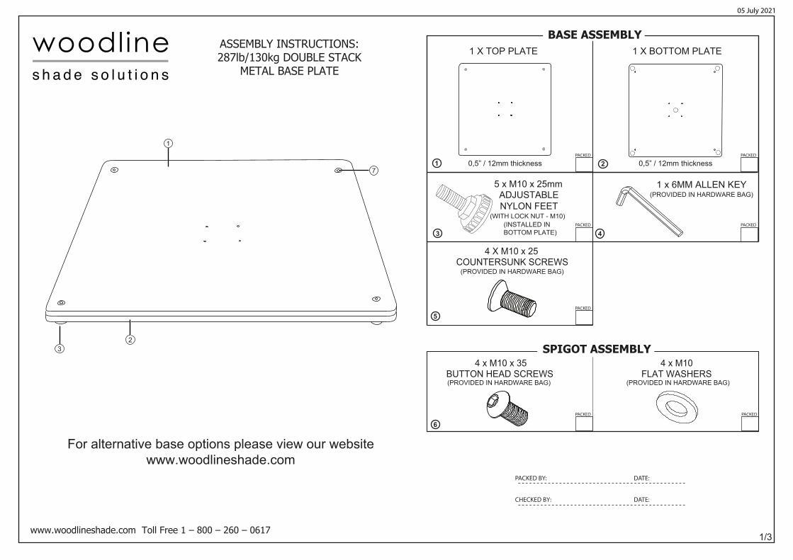
(PROVIDED IN HARDWARE BAG) (PROVIDED IN HARDWARE BAG)
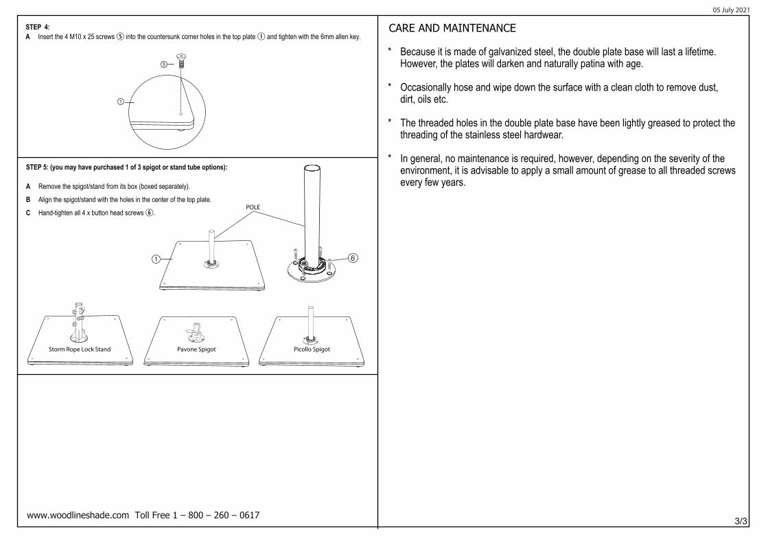
4 x M10 x 35BUTTON HEAD SCREWS
4 x M10FLAT WASHERS
0,5” / 12mm thickness 0,5” / 12mm thickness
(PROVIDED IN HARDWARE BAG)
(INSTALLED INBOTTOM PLATE)
5 x M10 x 25mmADJUSTABLENYLON FEET
1 x 6MM ALLEN KEY
(WITH LOCK NUT - M10)
4
5
6
1
3
2
1
32
7
BASE ASSEMBLY
SPIGOT ASSEMBLY
05 July 2021
For alternative base options please view our websitewww.woodlineshade.com
PACKED BY: DATE:
CHECKED BY: DATE:
PACKED
PACKED
PACKED
PACKED PACKED
PACKED
PACKED
1
2
3
2/3
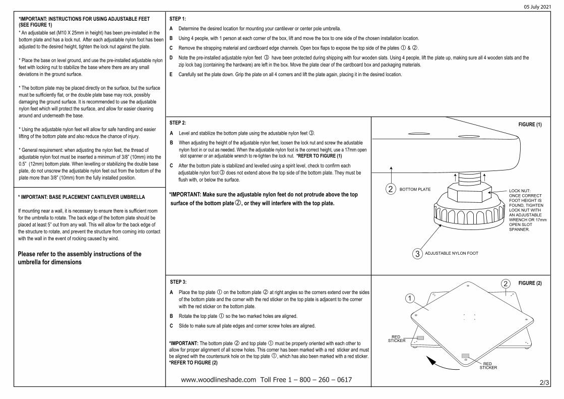
REDSTICKER
*IMPORTANT: INSTRUCTIONS FOR USING ADJUSTABLE FEET
* An adjustable set (M10 X 25mm in height) has been pre-installed in the bottom plate and has a lock nut.
feet with locking nut to stabilize the base where there are any small
* The bottom plate may be placed directly on the surface, but the surface must be sufficiently flat, or the double plate base may rock, possibly
* General requirement: when adjusting the nylon feet, the thread of each
0.5” (12mm) bottom plate. When levelling or stabilizing the double base
STEP 1:
A Determine the desired location for mounting your cantilever or center pole umbrella.
B Using 4 people, with 1 person at each corner of the box, lift and move the box to one side of the chosen installation location.
C Remove the strapping material and cardboard edge channels. Open box flaps to expose the top side of the plates � & �.
D zip lock bag (containing the hardware) are left in the box. Move the plate clear of the cardboard box an E Carefully set the plate down. Grip the plate on all 4 corners and lift the plate again, placing it in the desired location.
STEP 2:
A
B
*IMPORTANT: Make sure the adjustable nylon feet do not protrude above the top
STEP 3:
After the bottom plate is stabilized and levelled using a spirit level, check to confirm each
A Place the top plate � on the bottom plate � at right angles so the corners extend over the sides of the bottom plate and the corner with the red sticker on the top plate is adjacent to the corner with the red sticker on the bottom plate. B Rotate the top plate � so the two marked holes are aligned.
C Slide to make sure all plate edges and corner screw holes are aligned.
lifting of the bottom plate and also reduce the chance of injury.
adjusted to the desired height, tighten the lock nut against the plate.
damaging the ground surface. It is recommended to use the adjustable
2
REDSTICKER
BOTTOM PLATE
ADJUSTABLE NYLON FOOT
LOCK NUT:ONCE CORRECT FOOT HEIGHT IS FOUND, TIGHTEN LOCK NUT WITH AN ADJUSTABLE WRENCH OR 17mmOPEN SLOT SPANNER.
(SEE FIGURE 1)
FIGURE (1)
FIGURE (2)
C
* IMPORTANT: BASE PLACEMENT CANTILEVER UMBRELLA
If mounting near a wall, it is necessary to ensure there is sufficient room for the umbrella to rotate. The back edge of the bottom plate should be placed at least 5” out from any wall. This will allow for the back edge of the structure to rotate, and prevent the structure from coming into contact with the wall in the event of rocking caused by wind.
nylon feet which will protect the surface, and allow for easier cleaning
Please refer to the assembly instructions of theumbrella for dimensions
*IMPORTANT: The bottom plate � and top plate � must be properly oriented with each other to allow for proper alignment of all screw holes. This corner has been marked with a red sticker and must be aligned with the countersunk hole on the top plate �, which has also been marked with a red sticker.*REFER TO FIGURE (2)
d packaging materials.
After each adjustable nylon foot has been
* Place the base on level ground, and use the pre-installed adjustable nylon
deviations in the ground surface.
around and underneath the base.
* Using the adjustable nylon feet will allow for safe handling and easier
adjustable nylon foot must be inserted a minimum of 3/8” (10mm) into the
plate, do not unscrew the adjustable nylon feet out from the bottom of theplate more than 3/8” (10mm) from the fully installed position.
Note the pre-installed adjustable nylon feet � have been protected during shipping with four wooden slats. Using 4 people, lift the plate up, making sure all 4 wooden slats and the
Level and stabliize the bottom plate using the adustable nylon feet . �When adjusting the height of the adjustable nylon feet, loosen the lock nut and screw the adustablenylon foot in or out as needed. When the adjustable nylon foot is the correct height, use a 17mm open
*REFER TO FIGURE (1) slot spanner or an adjustable wrench to re-tighten the lock nut.
adjustable nylon foot � does not extend above the top side of the bottom plate. They must be flush with, or below the surface.
� surface of the bottom plate , or they will interfere with the top plate.
CARE AND MAINTENANCE
3/3
1
STEP 4:A Insert the 4 M10 x 25 screws into the countersunk corner holes in the top plate and tighten with the 6mm allen key.
* Because it is made of galvanized steel, the double plate base will last a lifetime. However, the plates will darken and naturally patina with age.
* Occasionally hose and wipe down the surface with a clean cloth to remove dust, dirt, oils etc.
* The threaded holes in the double plate base have been lightly greased to protect the threading of the stainless steel hardwear.
* In general, no maintenance is required, however, depending on the severity of the environment, it is advisable to apply a small amount of grease to all threaded screws every few years.