7
| Date post: | 23-Apr-2018 |
| Category: |
Documents |
| Upload: | nguyenlien |
| View: | 217 times |
| Download: | 2 times |
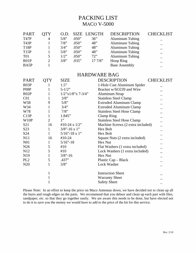
PACKING LIST MACO V-5000
PART QTY O.D. SIZE LENGTH DESCRIPTION CHECKLIST T47P 4 5/8” .050” 36” Aluminum Tubing _ T43P 1 7/8” .050” 48” Aluminum Tubing _ T18P 1 3/4” .050” 48” Aluminum Tubing _ T15P 1 5/8” .050” 48” Aluminum Tubing _ T01 5 1/2” .050” 72” Aluminum Tubing _ R01P 2 3/8” .035” 17 7/8” Hoop Ring _ BA5P 1 Base Assembly _
HARDWARE BAG PART QTY SIZE DESCRIPTION CHECKLIST R03P 1 1.5” 1-Hole Cast Aluminum Spider _ P08P 1 5-1/2” Bracket w/SO239 and Wire _ R02P 1 1/2”x1/8”x 7-3/4” Aluminum Strap _ C01 1 3/8” Stainless Steel Clamp _ W58 9 5/8” Extruded Aluminum Clamp _ W34 1 3/4” Extruded Aluminum Clamp _ W78 1 7/8” Stainless Steel Hose Clamp _ C13P 1 1.845” Clamp Ring _ W10P 2 1” Stainless Steel Hose Clamp _ S21 16 #10-24 x 1/2” Machine Screws (2 extra included) _ S23 1 3/8”-16 x 1” Hex Bolt _ S24 1 5/16”-18 x 1” Hex Bolt _ N11 16 #10-24 Square Nuts (2 extra included) _ N01 1 5/16”-18 Hex Nut _ N26 5 #10 Flat Washers (1 extra included) _ N12 5 #10 Lock Washers (1 extra included) _ N19 1 3/8”-16 Hex Nut _ PL2 5 .437” Plastic Cap – Black _ N20 1 3/8” Lock Washer _
1 Instruction Sheet _ 1 Warranty Sheet _ 1 Safety Sheet _
Please Note: In an effort to keep the price on Maco Antennas down, we have decided not to clean up all the burrs and rough edges on the parts. We recommend that you deburr and clean up each part with files, sandpaper, etc. so that they go together easily. We are aware this needs to be done, but have elected not to do it to save you the money we would have to add to the price of the kit for this service.
Rev. 2/10

MACO V-5000 26-33 MHz Base Station Antenna
ASSEMBLY INSTRUCTIONS
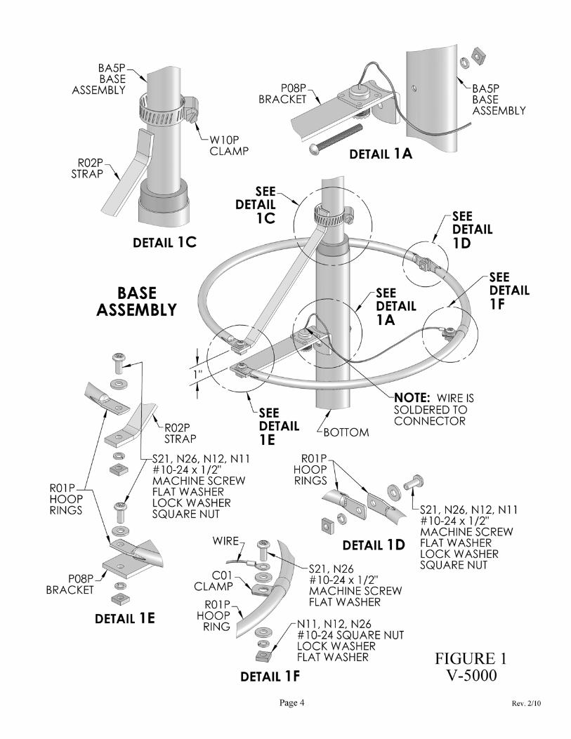
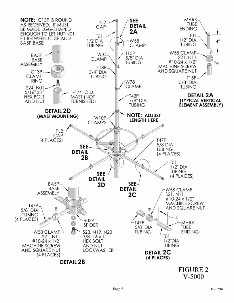
FIGURE 1 BASE ASSEMBLY Install the Bracket P08P to the Base Assembly BA5P (See Detail 1A). It should make a 90 degree angle with the base assembly. If not, bend the P08P until it does. Fasten one end of the Strap R02P (See Detail 1C) to the vertical end of the base section using Clamp W10P. Tighten snugly, but not too tight, as this may have to be adjusted. Next join together the two Hoop Rings R01P (See Detail 1D) using #10 Hardware S21, N26, N11, and N12. Now fasten one end of the hoop ring assembly to Bracket P08P (See Detail 1E) and the other end to Strap R02P using #10 Hardware S21, N26, N11, and N12. Position the aluminum Clamp C01 on the hoop ring assembly approximately where shown (See Detail 1F) and attach the wire as shown using #10 Hardware S21, N26, N12, and N11; do not tighten. Now measure from the center of the screw (See Detail 1D) around the outside of the ring 6-1/4” toward the P08P end of the hoop ring assembly until the edge of the clamp is against the mark; tighten snugly. Now make the final adjustment of Strap R02P so that the distance between the ends of the rings is 1”. This is a vertical separation of 1”. This 1” separation is a critical dimension (ignore the screws in this measurement) and tighten the clamp firmly. FIGURE 2 ELEMENT ASSEMBLY AND MAST MOUNTING To install the vertical elements T43P, T18P, T15P, and T01 use a felt tip marker and ruler, and mark 6” from one end. Mark the T01 4” from one end. Now using the clamps and hardware as shown (See Detail 2A) slide the ends into the larger sections to the mark and tighten clamps. Install the plastic Cap PL2 on the top. THE OVERALL LENGTH MUST BE SELECTED FROM THE FREQUENCY CHART ON THE NEXT PAGE AND ADJUSTED TO THIS MEASUREMENT. Shorten at top Clamp W10P. This is important to assure low SWR; however, the chart length is not sacred and may be changed to allow for variations in construction. For frequencies falling between those shown on the chart, it is suggested that interpolation be used to get the starting point for adjusting. Note: Overall length is the distance from the top of part T01 to the bottom of part BA5P. This is important as variations in base construction may cause the length at which the selected frequency has low SWR to vary. To install the radials, first put the cast aluminum Spider R03P bracket on the Base Assembly BA5P as shown (See Detail 2B). Install the 3/8”-16 x 1” Hex Bolt, Nut, and Lock Washer (S23, N19, and N20) in the bracket. The bracket is positioned so that there is 1/2” clearance between the top of the spider and the bottom of the Bracket P08P. Now tighten the hex bolt and nut. Next take the four T47P radials and Clamps W58 with #10-24 x 1/2” Machine Screws and Square Nuts (S21 and N11); place the clamps with the hardware installed over ends of the tubes. Now slide the radials onto the spider stubs (See Detail 2B) and tighten the clamps. Next take the four T01 radials and using a marking pen, mark 4” from one end on all four radials. Now using Clamps W58 with #10-24 x 1/2” Machine Screws and Square Nuts (S21 and N11); insert the marked end of the tubes to the mark and tighten the clamps (See Detail 2C). Install plastic Caps PL2 on the ends. Exact length is not critical.
Page 2 Rev. 2/10
MACO V-5000 ASSEMBLY INSTRUCTIONS
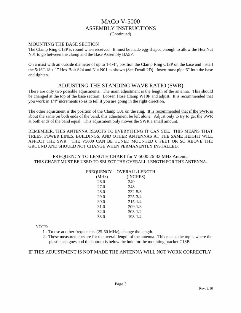
(Continued) MOUNTING THE BASE SECTION The Clamp Ring C13P is round when received. It must be made egg-shaped enough to allow the Hex Nut N01 to go between the clamp and the Base Assembly BA5P. On a mast with an outside diameter of up to 1-1/4”, position the Clamp Ring C13P on the base and install the 5/16”-18 x 1” Hex Bolt S24 and Nut N01 as shown (See Detail 2D). Insert mast pipe 6” into the base and tighten.
ADJUSTING THE STANDING WAVE RATIO (SWR) There are only two possible adjustments. The main adjustment is the length of the antenna. This should be changed at the top of the base section. Loosen Hose Clamp W10P and adjust. It is recommended that you work in 1/4" increments so as to tell if you are going in the right direction. The other adjustment is the position of the Clamp C01 on the ring. It is recommended that if the SWR is about the same on both ends of the band, this adjustment be left alone. Adjust only to try to get the SWR at both ends of the band equal. This adjustment only moves the SWR a small amount. REMEMBER, THIS ANTENNA REACTS TO EVERYTHING IT CAN SEE. THIS MEANS THAT TREES, POWER LINES, BUILDINGS, AND OTHER ANTENNAS AT THE SAME HEIGHT WILL AFFECT THE SWR. THE V5000 CAN BE TUNED MOUNTED 6 FEET OR SO ABOVE THE GROUND AND SHOULD NOT CHANGE WHEN PERMANENTLY INSTALLED.
FREQUENCY TO LENGTH CHART for V-5000 26-33 MHz Antenna THIS CHART MUST BE USED TO SELECT THE OVERALL LENGTH FOR THE ANTENNA.
FREQUENCY OVERALL LENGTH
(MHz) (INCHES) 26.0 249 27.0 248 28.0 232-5/8 29.0 225-3/4 30.0 215-1/4 31.0 209-1/8 32.0 203-1/2 33.0 198-1/4
NOTE: 1 - To use at other frequencies (25-50 MHz), change the length. 2 - These measurements are for the overall length of the antenna. This means the top is where the
plastic cap goes and the bottom is below the hole for the mounting bracket C13P. IF THIS ADJUSTMENT IS NOT MADE THE ANTENNA WILL NOT WORK CORRECTLY!
Page 3 Rev. 2/10
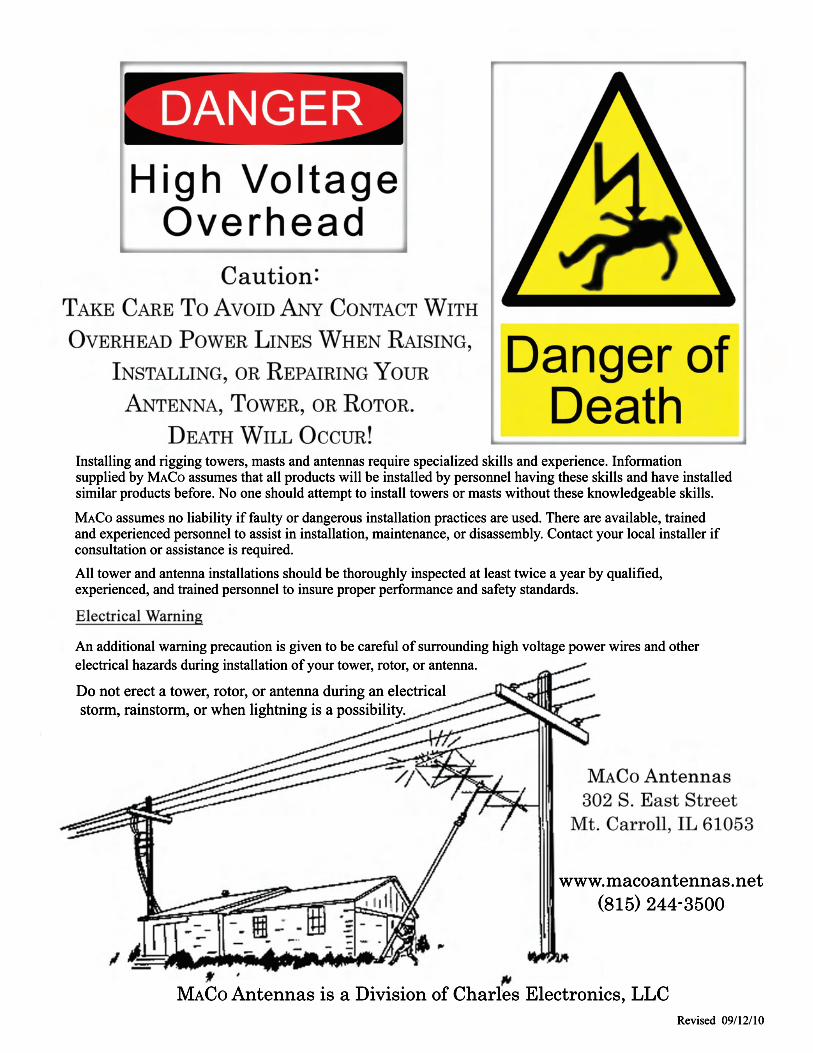
Installing and rigging towers, masts and antennas require specialized skills and experience. Informationsupplied by MACO assumes that all products will be installed by personnel having these skills and have installedsimilar products before. No one should attempt to install towers or masts without these knowledgeable skills.
MACO assumes no liability if faulty or dangerous installation practices are used. There are available, trainedand experienced personnel to assist in installation, maintenance, or disassembly. Contact your local installer ifconsultation or assistance is required.All tower and antenna installations should be thoroughly inspected at least twice a year by qualified,experienced, and trained personnel to insure proper performance and safety standards.
An additional warning precaution is given to be careful of surrounding high voltage power wires and otherelectrical hazards during installation of your tower, rotor, or antenna.
Revised 09/12/10
MACO Antennas is a Division of Charles Electronics, LLC
www.macoantennas.net(815) 244-3500
Do not erect a tower, rotor, or antenna during an electrical storm, rainstorm, or when lightning is a possibility.


