28
DOC022.53.80488 TU5200 11/2021, Edition 6 Basic User Manual

DOC022.53.80488
TU520011/2021, Edition 6Basic User Manual

Table of ContentsSection 1 Additional information ....................................................................... 3Section 2 Specifications ........................................................................................ 3Section 3 General information ............................................................................ 4
3.1 Safety information................................................................................................. 43.1.1 Use of hazard information.......................................................................... 43.1.2 Precautionary labels ................................................................................... 53.1.3 Class 2 laser product ................................................................................. 53.1.4 RFID module.............................................................................................. 6
3.1.4.1 Safety information for RFID modules............................................... 63.1.4.2 FCC conformance for RFID.............................................................. 7
3.1.5 Certification.................................................................................................73.2 Product overview.................................................................................................. 83.3 Product components ............................................................................................. 8
Section 4 Installation ............................................................................................... 94.1 Installation guidelines........................................................................................... 94.2 Connect to external devices (optional) ............................................................... 10
Section 5 User interface and navigation ...................................................... 10Section 6 Startup .....................................................................................................12Section 7 Operation ............................................................................................... 13
7.1 Configuration...................................................................................................... 137.1.1 Configure the instrument settings............................................................. 13
7.1.1.1 Change the language..................................................................... 147.1.2 Add operator IDs...................................................................................... 14
7.1.2.1 Configure an operator RFID tag (optional) ..................................... 157.1.3 Add sample IDs........................................................................................ 157.1.4 Configure the measurement settings........................................................167.1.5 Set the acceptance range.........................................................................16
7.2 Measurement ...................................................................................................... 177.2.1 Sample collection..................................................................................... 177.2.2 Prevent vial contamination....................................................................... 177.2.3 Prepare a sample vial ............................................................................... 177.2.4 Put the vial in the instrument .................................................................... 187.2.5 Measure the sample................................................................................. 197.2.6 Compare process and laboratory measurements .................................... 19
7.3 Show the recorded data......................................................................................20
Section 8 Calibration ............................................................................................. 21Section 9 Maintenance ......................................................................................... 22
9.1 Clean spills ......................................................................................................... 229.2 Clean the instrument ...........................................................................................229.3 Clean a sample vial ............................................................................................ 229.4 Clean the vial compartment ................................................................................ 23
Section 10 Troubleshooting ............................................................................... 23
1

Table of Contents
2
Section 1 Additional informationAn expanded user manual is available on the manufacturer's website.
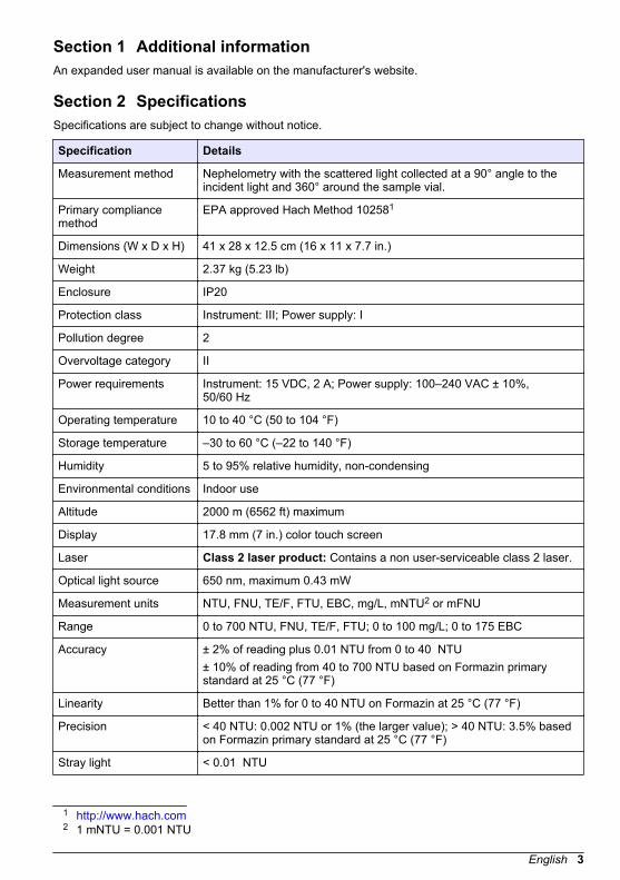
Section 2 SpecificationsSpecifications are subject to change without notice.
Specification Details
Measurement method Nephelometry with the scattered light collected at a 90° angle to theincident light and 360° around the sample vial.
Primary compliancemethod
EPA approved Hach Method 102581
Dimensions (W x D x H) 41 x 28 x 12.5 cm (16 x 11 x 7.7 in.)
Weight 2.37 kg (5.23 lb)
Enclosure IP20
Protection class Instrument: III; Power supply: I
Pollution degree 2
Overvoltage category II
Power requirements Instrument: 15 VDC, 2 A; Power supply: 100–240 VAC ± 10%,50/60 Hz
Operating temperature 10 to 40 °C (50 to 104 °F)
Storage temperature –30 to 60 °C (–22 to 140 °F)
Humidity 5 to 95% relative humidity, non-condensing
Environmental conditions Indoor use
Altitude 2000 m (6562 ft) maximum
Display 17.8 mm (7 in.) color touch screen
Laser Class 2 laser product: Contains a non user-serviceable class 2 laser.
Optical light source 650 nm, maximum 0.43 mW
Measurement units NTU, FNU, TE/F, FTU, EBC, mg/L, mNTU2 or mFNU
Range 0 to 700 NTU, FNU, TE/F, FTU; 0 to 100 mg/L; 0 to 175 EBC
Accuracy ± 2% of reading plus 0.01 NTU from 0 to 40 NTU± 10% of reading from 40 to 700 NTU based on Formazin primarystandard at 25 °C (77 °F)
Linearity Better than 1% for 0 to 40 NTU on Formazin at 25 °C (77 °F)
Precision < 40 NTU: 0.002 NTU or 1% (the larger value); > 40 NTU: 3.5% basedon Formazin primary standard at 25 °C (77 °F)
Stray light < 0.01 NTU
1 http://www.hach.com2 1 mNTU = 0.001 NTU
English 3

Specification Details
Calibration options StablCal®: 1-point calibration (20 NTU) for 0 to 40 NTU measurementrange; 2-point calibration (20 and 600 NTU) for 0 to 700 NTU (full)measurement rangeFormazin: 2-point calibration (20 NTU and dilution water) for 0 to 40 NTU measurement range; 3-point calibration (20 NTU, 600 NTU anddilution water) for 0 to 700 NTU (full) measurement rangeDegrees: 3-point calibration (20 and 100 mg/L and dilution water) for0 to 100 mg/L (full) measurement rangeSDVB: 3-point calibration (20 NTU, 600 NTU and dilution water) for 0 to700 NTU (full) measurement rangeCustom: 2- to 6-point custom calibration for a measurement range of 0 NTU to the highest calibration point.
Verification options Glass verification rod (secondary turbidity standard) < 0.1 NTU,StablCal or Formazin (0.1 to 40 NTU)
Verification (RFID orLink2SC®)
Process and laboratory measurements are compared with RFID orLink2SC for verification of the measurement value.
Certifications CE compliant; US FDA accession number: 1420493-xxx. This productcomplies with IEC/EN 60825-1 and to 21 CFR 1040.10 in accordancewith Laser Notice No. 50. Australian RCM.
Warranty 1 year (EU: 2 years)
Section 3 General informationIn no event will the manufacturer be liable for direct, indirect, special, incidental or consequentialdamages resulting from any defect or omission in this manual. The manufacturer reserves the right tomake changes in this manual and the products it describes at any time, without notice or obligation.Revised editions are found on the manufacturer’s website.
3.1 Safety informationThe manufacturer is not responsible for any damages due to misapplication or misuse of this productincluding, without limitation, direct, incidental and consequential damages, and disclaims suchdamages to the full extent permitted under applicable law. The user is soley responsible to identifycritical application risks and install appropriate mechanisms to protect processes during a possibleequipment malfunction.Please read this entire manual before unpacking, setting up or operating this equipment. Payattention to all danger and caution statements. Failure to do so could result in serious injury to theoperator or damage to the equipment.Make sure that the protection provided by this equipment is not impaired. Do not use or install thisequipment in any manner other than that specified in this manual.
3.1.1 Use of hazard information
D A N G E R Indicates a potentially or imminently hazardous situation which, if not avoided, will result in death orserious injury.
W A R N I N G Indicates a potentially or imminently hazardous situation which, if not avoided, could result in deathor serious injury.
4 English
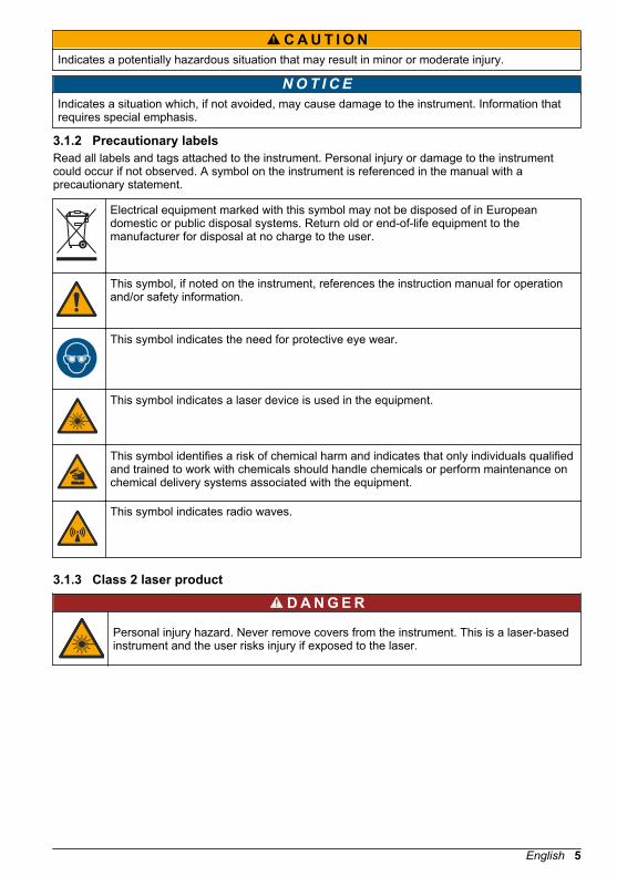
C A U T I O N Indicates a potentially hazardous situation that may result in minor or moderate injury.
NOT I CE Indicates a situation which, if not avoided, may cause damage to the instrument. Information thatrequires special emphasis.
3.1.2 Precautionary labelsRead all labels and tags attached to the instrument. Personal injury or damage to the instrumentcould occur if not observed. A symbol on the instrument is referenced in the manual with aprecautionary statement.
Electrical equipment marked with this symbol may not be disposed of in Europeandomestic or public disposal systems. Return old or end-of-life equipment to themanufacturer for disposal at no charge to the user.
This symbol, if noted on the instrument, references the instruction manual for operationand/or safety information.
This symbol indicates the need for protective eye wear.
This symbol indicates a laser device is used in the equipment.
This symbol identifies a risk of chemical harm and indicates that only individuals qualifiedand trained to work with chemicals should handle chemicals or perform maintenance onchemical delivery systems associated with the equipment.
This symbol indicates radio waves.
3.1.3 Class 2 laser product
D A N G E R
Personal injury hazard. Never remove covers from the instrument. This is a laser-basedinstrument and the user risks injury if exposed to the laser.
English 5
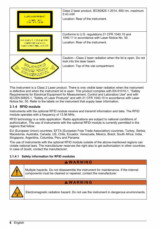
Class 2 laser product, IEC60825-1:2014, 650 nm, maximum0.43 mWLocation: Rear of the instrument.
Conforms to U.S. regulations 21 CFR 1040.10 and1040.11 in accordance with Laser Notice No. 50.Location: Rear of the instrument.
Caution—Class 2 laser radiation when the lid is open. Do notlook into the laser beam.Location: Top of the vial compartment.
This instrument is a Class 2 Laser product. There is only visible laser radiation when the instrumentis defective and when the instrument lid is open. This product complies with EN 61010-1, "SafetyRequirements for Electrical Equipment for Measurement, Control and Laboratory Use" and withIEC/EN 60825-1, "Safety of Laser Products" and with 21 CFR 1040.10 in accordance with LaserNotice No. 50. Refer to the labels on the instrument that supply laser information.
3.1.4 RFID moduleInstruments with the optional RFID module receive and transmit information and data. The RFIDmodule operates with a frequency of 13.56 MHz.RFID technology is a radio application. Radio applications are subject to national conditions ofauthorization. The use of instruments with the optional RFID module is currently permitted in theregions that follow:EU (European Union) countries, EFTA (European Free Trade Association) countries, Turkey, Serbia,Macedonia, Australia, Canada, US, Chile, Ecuador, Venezuela, Mexico, Brazil, South Africa, India,Singapore, Argentina, Columbia, Peru and PanamaThe use of instruments with the optional RFID module outside of the above-mentioned regions canviolate national laws. The manufacturer reserves the right also to get authorization in other countries.In case of doubt, contact the manufacturer.
3.1.4.1 Safety information for RFID modules
W A R N I N G
Multiple hazards. Do not disassemble the instrument for maintenance. If the internalcomponents must be cleaned or repaired, contact the manufacturer.
W A R N I N G
Electromagnetic radiation hazard. Do not use the instrument in dangerous environments.
6 English
NOT I CE This instrument is sensitive to electromagnetic and electromechanical interference. Theseinterferences can have an effect on the analysis performance of this instrument. Do not put thisinstrument near equipment that can cause interference.
Obey the safety information that follows to operate the instrument in accordance with local, regionaland national requirements.
• Do not operate the instrument in hospitals and equivalent establishments or near medicalequipment, such as pace makers or hearing aids.
• Do not operate the instrument near highly flammable substances, such as fuels, highly flammablechemicals and explosives.
• Do not operate the instrument near combustible gases, vapors or dust.• Keep the instrument away from strong vibration or shock.• The instrument can cause interference in immediate proximity to televisions, radios and
computers.• The warranty does not cover improper use or wear.
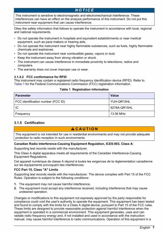
3.1.4.2 FCC conformance for RFIDThis instrument may contain a registered radio frequency identification device (RFID). Refer to Table 1 for the Federal Communications Commission (FCC) registration information.
Table 1 Registration information
Parameter Value
FCC identification number (FCC ID) YUH-QR15HL
IC 9278A-QR15HL
Frequency 13.56 MHz
3.1.5 Certification
C A U T I O N This equipment is not intended for use in residential environments and may not provide adequateprotection to radio reception in such environments.
Canadian Radio Interference-Causing Equipment Regulation, ICES-003, Class A:Supporting test records reside with the manufacturer.This Class A digital apparatus meets all requirements of the Canadian Interference-CausingEquipment Regulations.Cet appareil numérique de classe A répond à toutes les exigences de la réglementation canadiennesur les équipements provoquant des interférences.FCC Part 15, Class "A" LimitsSupporting test records reside with the manufacturer. The device complies with Part 15 of the FCCRules. Operation is subject to the following conditions:
1. The equipment may not cause harmful interference.2. The equipment must accept any interference received, including interference that may cause
undesired operation.
Changes or modifications to this equipment not expressly approved by the party responsible forcompliance could void the user's authority to operate the equipment. This equipment has been testedand found to comply with the limits for a Class A digital device, pursuant to Part 15 of the FCC rules.These limits are designed to provide reasonable protection against harmful interference when theequipment is operated in a commercial environment. This equipment generates, uses and canradiate radio frequency energy and, if not installed and used in accordance with the instructionmanual, may cause harmful interference to radio communications. Operation of this equipment in a
English 7
residential area is likely to cause harmful interference, in which case the user will be required tocorrect the interference at their expense. The following techniques can be used to reduceinterference problems:
1. Disconnect the equipment from its power source to verify that it is or is not the source of theinterference.
2. If the equipment is connected to the same outlet as the device experiencing interference, connectthe equipment to a different outlet.
3. Move the equipment away from the device receiving the interference.4. Reposition the receiving antenna for the device receiving the interference.5. Try combinations of the above.
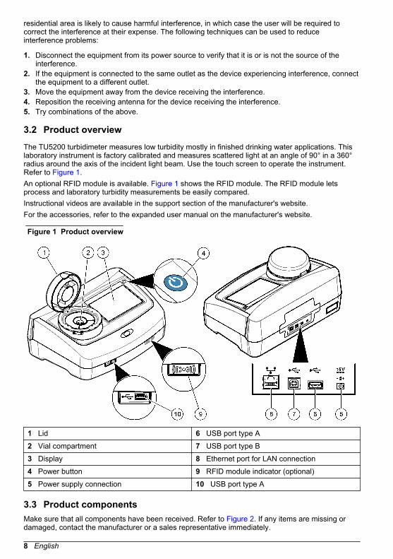
3.2 Product overviewThe TU5200 turbidimeter measures low turbidity mostly in finished drinking water applications. Thislaboratory instrument is factory calibrated and measures scattered light at an angle of 90° in a 360°radius around the axis of the incident light beam. Use the touch screen to operate the instrument.Refer to Figure 1.An optional RFID module is available. Figure 1 shows the RFID module. The RFID module letsprocess and laboratory turbidity measurements be easily compared.Instructional videos are available in the support section of the manufacturer's website.For the accessories, refer to the expanded user manual on the manufacturer's website.
Figure 1 Product overview
1 Lid 6 USB port type A2 Vial compartment 7 USB port type B3 Display 8 Ethernet port for LAN connection4 Power button 9 RFID module indicator (optional)5 Power supply connection 10 USB port type A
3.3 Product componentsMake sure that all components have been received. Refer to Figure 2. If any items are missing ordamaged, contact the manufacturer or a sales representative immediately.
8 English
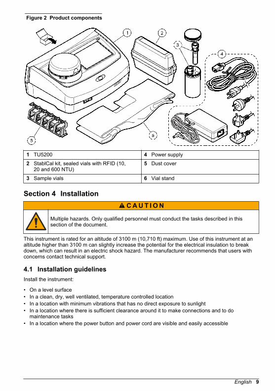
Figure 2 Product components
1 TU5200 4 Power supply2 StablCal kit, sealed vials with RFID (10,
20 and 600 NTU)5 Dust cover
3 Sample vials 6 Vial stand
Section 4 InstallationC A U T I O N
Multiple hazards. Only qualified personnel must conduct the tasks described in thissection of the document.
This instrument is rated for an altitude of 3100 m (10,710 ft) maximum. Use of this instrument at analtitude higher than 3100 m can slightly increase the potential for the electrical insulation to breakdown, which can result in an electric shock hazard. The manufacturer recommends that users withconcerns contact technical support.
4.1 Installation guidelinesInstall the instrument:
• On a level surface• In a clean, dry, well ventilated, temperature controlled location• In a location with minimum vibrations that has no direct exposure to sunlight• In a location where there is sufficient clearance around it to make connections and to do
maintenance tasks• In a location where the power button and power cord are visible and easily accessible
English 9

4.2 Connect to external devices (optional)NOT I CE
Network and access point security is the responsibility of the customer that uses the wirelessinstrument. The manufacturer will not be liable for any damages, inclusive however not limited toindirect, special, consequential or incidental damages, that have been caused by a gap in, orbreach of network security.
The instrument has three USB 1.1 ports and one Ethernet port. Refer to Figure 1 on page 8.USB type A port—Connect to a printer, barcode handset scanner, USB flash drive, keyboard3 orSIP 10 module.USB type B port—Connect to a PC.Ethernet port—Connect to a LAN with a shielded cable (e.g., STP, FTP, S/FTP). The maximumlength of the shielded cable is 20 m (65.6 ft). To set up a LAN connection at the instrument, refer tothe expanded user manual on the manufacturer's website .Note: USB cables must not be longer than 3 m (9.8 ft).
Section 5 User interface and navigationThe instrument display is a touch screen. Only use a clean, dry finger tip to navigate the functions ofthe touch screen. Do not use writing tips of pens or pencils or other sharp objects to make selectionson the screen or damage to the screen will occur.Refer to Figure 3 for an overview of the home screen.
3 As an alternative to the touchscreen, use a keyboard to enter text into text boxes on the display(e.g., passwords and sample IDs).
10 English

Figure 3 Display overview
1 Sample ID and measurement number4 7 UP/DOWN navigation arrows2 User comments 8 Sidebar menu (refer to Table 2)3 Instructions 9 Time and date4 Turbidity value, unit and reading mode 10 Options button5 Warning or error message 11 Read button6 Calibration status icon and calibration curve 12 Information (help) button
Table 2 Sidebar menu icons
Icon Description
Login
Logs in or logs out an operator. To log in, select an operator ID and then pushLogin. To log out, push Logout.Note: When an operator is logged in, the Login icon changes to the icon selected for the operator ID (e.g., fish,butterfly or soccer ball) and the text "Login" changes to the operator ID.
Sample ID
Selects the sample ID.
Calibration
Starts a calibration.
Verification
Starts a verification.
Link2SC
Compares process and laboratory measurements.
4 The measurement number increases by one each time a measurement is completed.
English 11

Table 2 Sidebar menu icons (continued)
Icon Description
Data Log
Shows the reading log, calibration log, verification log and compare log. Refer to Show the recorded data on page 20.
Setup
Configures the instrument settings. Refer to Configure the instrument settingson page 13.
Diagnostics
Shows the firmware information, instrument backup, instrument updates, signalinginformation and factory service data.
Timer
Sets a timer.
Goes to the manufacturer's website for the latest software versions and user manualwhen the instrument has a LAN connection.
Documents
Shows the user manual and video(s) for the instrument.
Section 6 StartupC A U T I O N
Personal injury hazard. Never remove covers from the instrument. This is a laser-basedinstrument and the user risks injury if exposed to the laser.
C A U T I O N
Personal injury hazard. Do not look into the vial compartment when the instrument isconnected to power.
Refer to the illustrated steps that follow to connect power to the instrument and start the instrument.When the language menu shows, select the language and then push OK. The self-check will start.Note: To change the language after the initial startup, refer to Change the language on page 14.
12 English

Section 7 Operation
7.1 Configuration7.1.1 Configure the instrument settings
1. Push two times, then push Setup.2. Select an option.
Option Description
Location Sets the location name of the instrument. The location is saved withmeasurements to the data log.
Date & Time Sets the date format, the time format and the date and time. Enter thecurrent date and time. Date Format—Sets the date format. Options: dd-mmm-yyyy (default), yyyy-mm-dd, dd-mm-yyyy or mm-dd-yyyy. TimeFormat—Sets the time format. Options: 12 or 24 hours (default).
Security Enables or disables password protection for the settings and tasks in thesecurity list. Security Password—Sets or changes the security(administrator) password (10 characters maximum). Passwords are casesensitive. Security List—Sets the security level for each setting and task inthe security list.
• Off—All operators can change the setting and or do the task.• One key—Only operators with a one-key or two-key security level can
change the setting or do the task. Refer to Add operator IDs on page 14.• Two keys—Only operators with a two-key security level can change the
setting or do the task.
Note: The Security setting is not set to on until Close is pushed.
Sound Settings Enables or disables the sound settings for individual events. Sets the soundvolume for each event (1 to 10). To enable or disable all of the soundsettings, select All and then push Setup.
English 13
Option Description
Network &Peripherals
Shows the connection status of the devices that are directly connected to theinstrument and connected to the instrument by LAN (local area network).
• Printer—Local printer or network printer• Network—LAN connection• Controller—sc controller(s)• PC• USB Memory—USB flash drive• Keyboard
PowerManagement
Sets when the instrument is automatically set to sleep mode or off after aperiod of no activity. Sleep Timer—Sets when the instrument is set to sleepmode. Options: OFF, 30 minutes, 1 (default), 2 or 12 hours. Power-OffTimer—Sets when the instrument is set to off. Options: OFF, 2, 6,12 (default) or 24 hours.
7.1.1.1 Change the language
NOT I CE Wait a minimum of 20 seconds after the power is set to off before the power is set to on again ordamage to the instrument can occur.
To change the language after the initial startup, do the steps that follow.
1. Set the instrument to off.2. Set the instrument to on.3. During startup, touch the display until the language menu shows (approximately 45 seconds).4. When the language menu shows, select the language and then push OK.
7.1.2 Add operator IDsAdd a unique operator ID for each person who will measure samples (30 maximum). Select an icon,operator password and security level for each operator ID.
1. Push Login.2. Push Options>New.3. Enter a new operator ID (10 characters maximum), then push OK.4. Push the LEFT and RIGHT arrows to select the icon for the operator ID (e.g., fish, butterfly or
soccer ball).5. Push Operator Password, then enter a password for the operator ID.
Note: Passwords are case sensitive.
6. Push Security Level, then select the security level for the operator ID.
• Off—The operator cannot change the settings or do the tasks in the Security settings that havea security level of one key or two keys.
• One key—The operator can change all the settings and do all the tasks in the Security settingsthat have a security level of off or one key.
• Two keys—The operator can change all the settings and do all the tasks in the Securitysettings.
Note: Before a security level can be selected, the Security setting must be set to on. Refer to Configure theinstrument settings on page 13.
7. Push OK>Close.
14 English

8. To edit an operator ID, select the operator ID and then push Options>Edit.9. To delete an operator ID, select the operator ID and then push Options>Delete>OK.
7.1.2.1 Configure an operator RFID tag (optional)To use an operator RFID tag to log in to the instrument, save the applicable operator ID to anoperator RFID tag as follows:
1. Push Login.2. Select the operator ID, then push Options>Initialize RFID Tag.3. Enter the password for the operator ID as necessary.4. Complete the steps that show on the display.5. Push OK to replace the operator ID on the RFID tag with a new operator ID if applicable.6. Push Close.7. Put the operator RFID tag in front of the RFID module to log in.
7.1.3 Add sample IDsAdd a unique sample ID for each sample (100 maximum). The sample ID identifies the samplelocation or other sample specific information.As an alternative, import sample IDs from a spreadsheet file to the instrument. Refer to the expandeduser manual on the manufacturer's website to import sample IDs.Note: When a sample bottle with a sample RFID sticker is put in front of the RFID module, the sample ID isautomatically added to the instrument and selected on the instrument.
1. Push Sample ID.2. Push Options>New.3. Enter a new sample ID (20 characters maximum).4. If the sample bottle has a barcode that identifies the sample ID, read the barcode with a barcode
handset scanner that is connected to the instrument. The barcode is added to the sample ID.5. Push OK.6. Select an option.
Option Description
Add Date/Time Adds the data and time that the sample was collected to the sample ID(optional). The date and time entered for each sample ID show on the SampleID menu.
Add Number Adds a measurement number to the sample ID (optional). Select the firstnumber used for the measurement number (0 to 999).The measurement number shows in parenthesis after the sample ID on thehome screen. Refer to Figure 3 on page 11.
Add Color Adds a colored circle to the sample ID icon (optional). The sample ID iconshows before the sample ID on the home screen. Refer to Figure 3on page 11.
7. Push OK>Close.8. To edit a sample ID, select the sample ID and then push Options>Edit>OK.9. To delete a sample ID, select the sample ID and then push Options>Delete>OK.
English 15

7.1.4 Configure the measurement settingsSelect the reading mode, measurement units, data log settings, resolution and more.
1. At the main reading screen, push Options>Reading Setup.2. Select an option.
Option Description
Reading Sets the reading mode to single, continuous or minimum mode. Default:Single. Single—The measurement stops when the reading is stable.Continuous—The measurement continues until the user pushes Done.Minimum Mode—Set to on when a process and laboratory measurement arecompared and the process measurement is a lower NTU range. Removes theeffect of non-representative particles in the grab sample. Signal Avg—Theturbidity reading that shows on the display is an average of the valuesmeasured during the time interval selected. Options: For single measurementmode, 5 to 15 seconds. For continuous measurement mode, 5 to 90 seconds.
Unit Selects the measurement units that show on the display and that are recordedto the data log. Options: NTU, FNU, TE/F, FTU, EBC, mNTU or mFNU.Default: NTU ).
Data LogSetup
Sets the data log settings. Auto Store—Measurement data is automaticallyrecorded in the reading log. Default: On. When not selected, pushOptions>Store to record the current measurement to the reading log asnecessary. Send Data Format—Sets the output format of measurement datathat is sent to external devices (CSV or XML). Default: XML. Print Format—Sets the output format of measurement data that is sent to a printer (QuickPrint or Detailed Print (GLP)). Comments—Lets users add comments to logentries. Auto Send—Measurement data is automatically sent to all of thedevices (e.g., printer, USB flash drive and FTP server) that are connected tothe instrument after each measurement.
Resolution Selects the number of decimal places that show on the display. Options:0.001 (default) or 0.0001.
Bubble Reject Sets the bubble reject to on (default) or off. When set to on, high turbidityreadings caused by bubbles in the sample are not shown or saved to the datalog.
Close lid tostart reading
Enables or disables the instrument to start a measurement automatically whenthe lid is closed. Default: On. A measurement is only done when there is asample vial in the instrument.
7.1.5 Set the acceptance rangeBefore process and laboratory measurements are compared on the instrument, set the acceptancerange for the compare results. The acceptance range is the maximum difference permitted betweenthe process and laboratory measurements.
1. Push LINK2SC.2. Push Options>Compare Setup.3. Push Acceptance Range>Unit.4. Select an option.
Option Description
% Sets the acceptance range to a percentage (1 to 99%).
NTU Sets the acceptance range to NTU units (0.015 to 100.00 NTU).
5. Push Value, then enter the acceptance range.
16 English

7.2 Measurement7.2.1 Sample collection
• Collect samples in clean glass or plastic bottles with tight-fitting caps.• Rinse the container a minimum of three times with the sample.• When collecting a sample from a water tap in a distribution system or treatment plant, turn the
water on for at least five minutes, then collect the sample. Do not adjust the flow because this canadd particles.
• When collecting a sample from a body of water (e.g., a stream or storage tank), collect at least oneliter (1 quart) and fully mix before taking an aliquot for measurement. If the quality of the samplesource is not constant, collect samples at many locations at different depths as necessary. Then,mix the samples together to prepare one sample for measurement.
• Fill the container. Let the container overflow with the sample and then immediately put the cap onthe sample container so that there is no headspace (air) above the sample.
• Write the sample information on the container.• Start analysis as soon as possible to prevent temperature changes, bacteria growth and settling.
7.2.2 Prevent vial contaminationNOT I CE
Do not to touch or scratch the glass of the sample vial. Contamination or scratches on the glass cancause measurement errors.
The glass must stay clean and have no scratches. Use a no-lint cloth to remove dirt, fingerprints orparticles from the glass. Replace the sample vial when the glass has scratches.Refer to Figure 4 to identify where not to touch the sample vial. Always keep the sample vials in thevial stand to prevent contamination on the bottom of the vial.
Figure 4 Sample vial overview
1 Measurement surface—Do not touch.
7.2.3 Prepare a sample vial
C A U T I O N
Chemical exposure hazard. Dispose of chemicals and wastes in accordance with local,regional and national regulations.
English 17

NOT I CE Always put a cap on the sample vial to prevent spills in the vial compartment.
Refer to the illustrated steps that follow to prepare a sample vial for measurement. Measure thesample immediately.Note: If there is contamination in the sample vial after it is rinsed with the sample, clean the sample vial. Refer to Clean a sample vial on page 22.
7.2.4 Put the vial in the instrument
C A U T I O N
Personal injury hazard. Never remove covers from the instrument. This is a laser-basedinstrument and the user risks injury if exposed to the laser.
18 English
C A U T I O N
Personal injury hazard. Do not look into the vial compartment when the instrument isconnected to power.
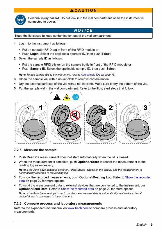
NOT I CE Keep the lid closed to keep contamination out of the vial compartment.
1. Log in to the instrument as follows:
• Put an operator RFID tag in front of the RFID module or• Push Login. Select the applicable operator ID, then push Select.
2. Select the sample ID as follows:
• Put the sample RFID sticker on the sample bottle in front of the RFID module or• Push Sample ID. Select the applicable sample ID, then push Select.
Note: To add sample IDs to the instrument, refer to Add sample IDs on page 15.
3. Clean the sample vial with a no-lint cloth to remove contamination.4. Dry the external surfaces of the vial with a no-lint cloth. Make sure to dry the bottom of the vial.5. Put the sample vial in the vial compartment. Refer to the illustrated steps that follow.
7.2.5 Measure the sample
1. Push Read if a measurement does not start automatically when the lid is closed.2. When the measurement is complete, push Options>Store to record the measurement to the
reading log as necessary.Note: If the Auto Save setting is set to on, "Data Stored" shows on the display and the measurement isautomatically recorded to the reading log.
3. To show the recorded measurements, push Options>Reading Log. Refer to Show the recordeddata on page 20 for more options.
4. To send the measurement data to external devices that are connected to the instrument, pushOptions>Send Data. Refer to Show the recorded data on page 20 for more options.Note: If the Auto Send settings is set to on, the measurement data is automatically sent to the externaldevice(s) that is connected to the instrument.
7.2.6 Compare process and laboratory measurementsRefer to the expanded user manual on www.hach.com to compare process and laboratorymeasurements.
English 19
7.3 Show the recorded dataAll the recorded data is kept in the data log. The data log is divided into four logs:
• Reading log—Shows the recorded measurements.• Calibration log—Shows the calibration history.• Verification log—Shows the verification history.• Compare log—Shows the recorded comparisons of process and laboratory measurements.
1. Push Data Log and select the applicable log to show.2. To show the details of a log entry, select the log entry and then push View Details.
Note: To add a comment to the log entry, push the comments icon.
3. To only show the log entries recorded during a time interval or with a specific operator ID orsample ID, do the steps that follow.
a. Push Filter, then select On.b. Select an option.
Option Description
Time Interval Selects the time interval.
Operator ID Selects the operator ID.
Sample ID Selects the sample ID. This option only shows when Reading Log orCompare Log is selected.
4. To send log data to a device (e.g., printer or USB flash drive), delete a log entry or show acompare log or reading log entries in a graph, do the steps that follow.
a. Push Options.
20 English

b. Select an option.
Option Description
Delete Removes one of the items that follow.
• The selected log entry• The log entries for a time interval• The log entries with a specific operator ID• The log entries with a specific sample ID5
• All the entries in the selected log
SendData
Sends one of the items that follow to all the devices that are directly connectedto the instrument (e.g., printer or USB flash drive) and connected to theinstrument by LAN (network printer or FTP server).
• The selected log entry• The log entries for a time interval• The log entries with a specific operator ID• The log entries with a specific sample ID5
• All the entries in the selected log
ViewGraph
Shows the reading log entries that have the same sample ID in a graph. Thisoption only shows when Compare Log or Reading Log is selected.To add the log entries for another sample ID to the graph, push Options>AddData. Select a sample ID to add to the graph.To show the details of a data point, touch a data point on the display or push theLEFT and RIGHT arrows to select a data point.Data points—Selects the symbol used for the data points. Control Limit—Setsthe minimum value and maximum value of the readings that show on the graph.
Section 8 CalibrationW A R N I N G
Chemical exposure hazard. Obey laboratory safety procedures and wear all of thepersonal protective equipment appropriate to the chemicals that are handled. Refer tothe current safety data sheets (MSDS/SDS) for safety protocols.
When the instrument is used for US EPA regulatory reporting, calibrations must be done according toUS EPA guidance documents and methodologies. Contact local regulating authorities for additionalcompliance regulations.The instrument is factory calibrated and the laser light source is stable. The manufacturerrecommends that a calibration verification be done periodically to make sure that the systemoperates as intended. The manufacturer recommends calibration after repairs or comprehensivemaintenance work.Refer to the expanded user manual on the manufacturer's website to calibrate the instrument and doa calibration verification.
5 This option only shows when Reading Log or Compare Log is selected.
English 21
Section 9 MaintenanceC A U T I O N
Multiple hazards. Only qualified personnel must conduct the tasks described in thissection of the document.
C A U T I O N Chemical exposure hazard. Obey laboratory safety procedures and wear all of thepersonal protective equipment appropriate to the chemicals that are handled. Refer tothe current safety data sheets (MSDS/SDS) for safety protocols.
C A U T I O N
Personal injury hazard. Never remove covers from the instrument. This is a laser-basedinstrument and the user risks injury if exposed to the laser.
NOT I CE Do not disassemble the instrument for maintenance. If the internal components must be cleaned orrepaired, contact the manufacturer.
9.1 Clean spillsC A U T I O N
Chemical exposure hazard. Dispose of chemicals and wastes in accordance with local,regional and national regulations.
1. Obey all facility safety protocols for spill control.2. Discard the waste according to applicable regulations.
9.2 Clean the instrumentClean the exterior of the instrument with a moist cloth, and then wipe the instrument dry.
9.3 Clean a sample vialC A U T I O N
Chemical exposure hazard. Obey laboratory safety procedures and wear all of thepersonal protective equipment appropriate to the chemicals that are handled. Refer tothe current safety data sheets (MSDS/SDS) for safety protocols.
Clean the sample vial when there is contamination in the sample vial after the sample vial is rinsed.Items to collect:
• Hydrochloric acid (concentration 10%)• Laboratory cleaning detergent for glass (concentration 0.1%)• Distilled or deonized water• Dilution water• Vial wiper (optional)• No-lint cloth
22 English

1. Put the exterior and interior surfaces of the sample vial and the cap in 10% hydrochloric acid for15 minutes.
2. Clean the exterior and interior surfaces of the sample vial and the cap with laboratory cleaningdetergent for glass (concentration 0.1%).
3. Fully rinse the sample vial three times with distilled or deionized water.Note: If the sample vial is used to measure low range turbidity samples or dilution water, rinse with dilutionwater (not distilled or deionized water).
4. For the best results, clean the sample vial with the optional vial wiper. Then fully rinse the samplevial again. Refer to Figure 5.
5. Dry the external surfaces of the sample cell with a soft, no-lint cloth. Do not let the sample vial airdry.
6. For storage, fill the sample vial with distilled or demineralized water.Note: If the sample vial is used to measure low range turbidity samples or dilution water, fill the sample vial withdilution water (not distilled or deionized water).
7. Immediately put the cap on the sample vial to keep the interior of the sample vial wet.
Figure 5 Clean the vial with the vial wiper (optional)
9.4 Clean the vial compartmentClean the vial compartment only when the compartment has contamination. Make sure that the toolto clean the vial compartment has a soft surface and does not damage the instrument. Table 3shows the options on how to clean the vial compartment.
Table 3 Cleaning options
Contaminant Options
Dust Vial compartment wiper, micro fiber cloth, lint-free cloth
Liquid, oil Cloth, water and cleaning agent
Section 10 TroubleshootingRefer to the expanded user manual on www.hach.com for troubleshooting information.
English 23

24 English


*DOC022.53.80488*
HACH COMPANY World HeadquartersP.O. Box 389, Loveland, CO 80539-0389 U.S.A.Tel. (970) 669-3050(800) 227-4224 (U.S.A. only)Fax (970) [email protected]
HACH LANGE GMBHWillstätterstraße 11D-40549 Düsseldorf, GermanyTel. +49 (0) 2 11 52 88-320Fax +49 (0) 2 11 52 [email protected]
HACH LANGE Sàrl6, route de Compois1222 VésenazSWITZERLANDTel. +41 22 594 6400Fax +41 22 594 6499
© Hach Company/Hach Lange GmbH, 2015–2019, 2021.All rights reserved. Printed in Germany.


