7 Before you start. BEFORE YOU START The water softener requires a minimum water flow of 3 gallons per minute at the inlet. Maximum allowable inlet water pressure is 125 psi. If daytime pressure is over 80 psi, nighttime pressure may exceed the maximum. Use a pressure reducing valve if necessary (Adding a pressure reducing valve may reduce the flow). If your home is equipped with a back flow preventer, an expansion tank must be installed in accordance with local codes and laws. The water softener uses a direct plug-in external power supply (included). Be sure to use the included power supply and plug it into a nominal 120V, 60 cycle household outlet that is in a dry location only, grounded and properly protected by an over current device such as a circuit breaker or fuse. Do not use this system to treat water that is microbiologically unsafe or of unknown quality without adequate disinfection upstream or downstream of the system. INSPECT SHIPMENT The parts required to assemble and install the water softener are included with the unit. Thoroughly check the water softener for possible shipping damage and parts loss. Also inspect and note any damage to the shipping carton. Remove and discard (or recycle) all packing materials. To avoid loss of small parts, we suggest you keep the small parts in the parts bag until you are ready to use them. Ground Clamp Kit Bypass Valve 12 ft. Drain Hose Clips Installation Adaptors Hose Clamps Overflow Adapter Grommet WARNING! Discard all unused parts and packaging material after installation. Small parts remaining after the installation could be a choke hazard. Pliers Screwdriver Teflon tape Razor knife Two adjustable wrenches Additional tools may be required if modification to home plumbing is necessary. TOOLS AND MATERIALS REQUIRED FOR INSTALLATION NOTE: Failure to comply with these installation instructions will void the product warranty, and the installer will be responsible for any service, repair or damages caused thereby. Silicone Grease
Transcript
7
Before you start.BEFORE YOU START
The water softener requires a minimum water flow of 3 gallons per minute at the inlet. Maximum allowable inlet water pressure is 125 psi. If daytime pressure is over 80 psi, nighttime pressure may exceed the maximum. Use a pressure reducing valve if necessary (Adding a pressure reducing valve may reduce the flow). If your home is equipped with a back flow preventer, an expansion tank must be installed in accordance with local codes and laws.
The water softener uses a direct plug-in external power supply (included). Be sure to use the included power supply and plug it into a nominal 120V, 60 cycle household outlet that is in a dry location only, grounded and properly protected by an over current device such as a circuit breaker or fuse. Do not use this system to treat water that is microbiologically unsafe or of unknown quality without adequate disinfection upstream or downstream of the system.
INSPECT SHIPMENTThe parts required to assemble and install the water softener are included with the unit. Thoroughly check the water softener for possible shipping damage and parts loss. Also inspect and note any damage to the shipping carton.Remove and discard (or recycle) all packing materials. To avoid loss of small parts, we suggest you keep the small parts in the parts bag until you are ready to use them.
Ground ClampKit
Bypass Valve 12 ft. Drain Hose
Clips Installation Adaptors
Hose Clamps Overflow Adapter
Grommet
WARNING! Discard all unused parts and packaging material after installation. Small parts remaining after the installation could be a choke hazard.
Pliers Screwdriver Teflon tape
Razor knife Two adjustable wrenches Additional tools may be required if modification to home plumbing is necessary.
TOOLS AND MATERIALS REQUIRED FOR INSTALLATION
NOTE: Failure to comply with these installation instructions will void the product warranty, and the installer will be responsible for any service, repair or damages caused thereby.
Silicone Grease
8
Installation Requirements.
14-7/16"
TOP VIEW
SIDE VIEW FRONT VIEW
43-1/4"
22-7/16"
3-3/8" IN
OUT
37"
IN - OUT
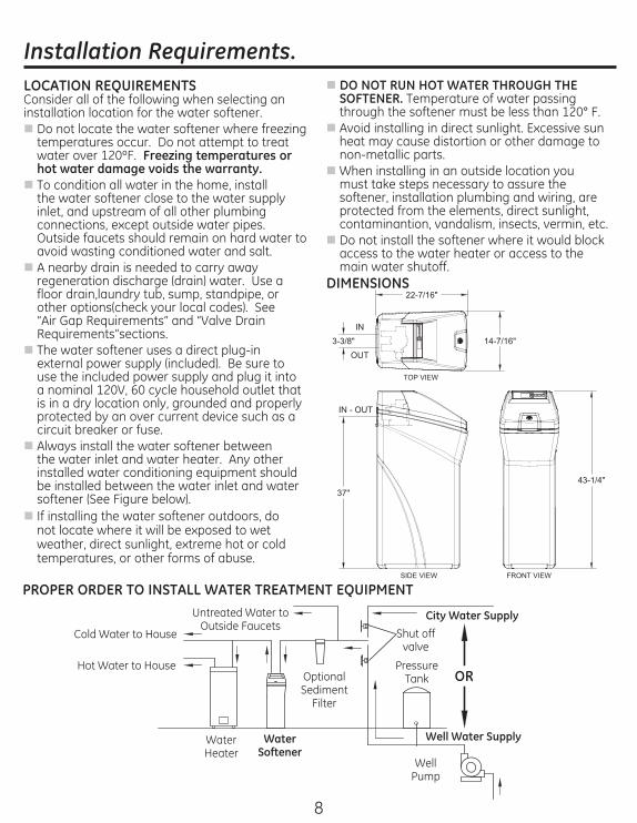
LOCATION REQUIREMENTSConsider all of the following when selecting an installation location for the water softener.
Do not locate the water softener where freezing temperatures occur. Do not attempt to treat water over 120ºF. Freezing temperatures or hot water damage voids the warranty.
To condition all water in the home, install the water softener close to the water supply inlet, and upstream of all other plumbing connections, except outside water pipes. Outside faucets should remain on hard water to avoid wasting conditioned water and salt.
A nearby drain is needed to carry away regeneration discharge (drain) water. Use a floor drain,laundry tub, sump, standpipe, or other options(check your local codes). See “Air Gap Requirements” and “Valve Drain Requirements”sections.
The water softener uses a direct plug-in external power supply (included). Be sure to use the included power supply and plug it into a nominal 120V, 60 cycle household outlet that is in a dry location only, grounded and properly protected by an over current device such as a circuit breaker or fuse.
Always install the water softener between the water inlet and water heater. Any other installed water conditioning equipment should be installed between the water inlet and water softener (See Figure below).
If installing the water softener outdoors, do not locate where it will be exposed to wet weather, direct sunlight, extreme hot or cold temperatures, or other forms of abuse.
DO NOT RUN HOT WATER THROUGH THE SOFTENER. Temperature of water passing through the softener must be less than 120° F.
Avoid installing in direct sunlight. Excessive sun heat may cause distortion or other damage to non-metallic parts.
When installing in an outside location you must take steps necessary to assure the softener, installation plumbing and wiring, are protected from the elements, direct sunlight, contaminantion, vandalism, insects, vermin, etc.
Do not install the softener where it would block access to the water heater or access to the main water shutoff.
DIMENSIONS
PROPER ORDER TO INSTALL WATER TREATMENT EQUIPMENT
Well Pump
Well Water Supply
City Water Supply
ORPressure
TankOptional Sediment
Filter
Water Heater
Water Softener
Hot Water to House
Cold Water to House
Untreated Water to Outside Faucets
Shut off valve
9
Installation Requirements.PLUMBING CODESAll plumbing must be completed in accordance with national, state and local plumbing codes.
In the state of Massachusetts: The Commonwealth of Massachusetts plumbing code 248-CMR shall be adhered to. A licensed plumber shall be used for this installation.
AIR GAP REQUIREMENTSA drain is needed for regeneration water (See Figure 1). A floor drain, close to the water softener, is preferred. A laundry tub, standpipe, etc. are other drain options. Secure valve drain hose in place. Leave an air gap of 1-1/2” between the end of the hose and the drain. This gap is needed to prevent back flow of sewer water into the water softener. Do not put the end of the drain hose into the drain.
VALVE DRAIN REQUIREMENTSUsing the flexible drain hose (included) (See Figure 2), measure and cut to the length needed. Flexible drain hose is not allowed in all localities (check your plumbing codes). If local codes do not allow use of a flexible drain hose, a rigid valve drain run must be used. Purchase a compression fitting (1/4 NPT x 1/2 in. minimum tube) and 1/2” tubing from your local hardware store. Plumb a rigid drain as needed (See Figure 3).NOTE: Avoid drain hose runs longer than 30 feet. Avoid elevating the hose more than 8 feet above the floor. Make the valve drain line as short and direct as possible.
FLEXIBLE DRAIN LINE
RIGID DRAIN LINE
FlOOR DRAIN STANDPIPE LAUNDRY TUB
1-1/2” air gap
1-1/2” air gap
1-1/2” air gap
Drain Hose
Drain Hose
Drain Hose
Figure 1
Barbs for 3/8 I.D. tubingHose clamp
Drain hose
1/4” NPT Thread
Figure 2
Clip
1/4 NPT thread
1/2 outside diameter copper tube (not provided)
Compression fitting 1/4 NPT x 1/2 O.D. tube (not provided)
Cut barbs from valve drain elbow (pull clip and remove drain valve elbow from valve)
Barbs
Figure 3
Drain hose adapter
10
Installation Requirements.INLET/OUTLET PLUMBING REQUIREMENTSAlways install either a single bypass valve (provided),as shown in Figure 4, or, if desired, parts for a 3 valve bypass system (not included) can be purchased and assembled, as shown in Figure 5. Bypass valves allow you to turn off water to the softener for maintenance if needed, but still have water in house pipes.Pipe fittings must be 1/2” minimum. Use:
IMPORTANT: Do not solder with plumbing attached to installation adaptors and single bypass valve. Soldering heat will damage the adaptors and valve.
DANGER: Electric Shock Hazard: Install metal ground clamp to metal house water supply pipe before beginning installation. Securely tighten connection in center of metal ground clamp. Failure to do so can result in death or electric shock.
3-VALVE BYPASS SYSTEMFor soft water service: Open the inlet and outlet valves and close the bypass valve.For bypass hard water: Close the inlet and outlet valves and open the bypass valve.
3 VALVE BYPASS
Bypass Valve
Outlet Valve
Inlet Valve
From Water Softener
To Water Softener
Figure 5
SINGLE BYPASS VALVE
Pull out for “Service” (Soft water)
Push in for “Bypass”
Figure 4
Installation adaptors
11
Installation Instructions.TYPICAL INSTALLATION
Clips
Inlet
Outlet
Lubricated O-ring
Single Bypass Valve
O-ring
1” NPT Threaded Adaptor
1” NPT Sweat Adaptor (not included)
Pipe
Ground Clamp
1-1/2” air gap
Floor Drain
Secure Valve Drain Hose in place over Floor Drain
BrineTank Overflow Hose*
Overflow Adapter
Ground Clamp
Conditioned Water
Main Water Pipe
Incoming-Hard Water
Hard Waterto Outside Faucets
Bypass Valve Assembly
Plug-in Transformer
To Controller
Drain Hose Adapter
Valve Drain Hose*
*Do not connect the water softener valve drain hose to the brine tank overflow
NOTE: See “Air Gap Requirements” section.
Figure 6
Figure 7
Top Cover
Brine Tank (Salt Storage)
Drain Hose Adapter
Clips
Figure 8
Turbine
Valve outlet
Turbine shaft and supportPlastic shipping plug
NOTE: Be sure the turbine and support are firmly in place in the valve outlet. Blow into the valve port and observe the turbine for free rotation.
12
Installation Instructions.TURN OFF WATER SUPPLY1. Close the main water supply valve, located near
the well pump or water meter.2. Open all faucets to drain all water from house
pipes.NOTE: Be sure not to drain water from the water heater, as damage to the water heater elements could result.
INSTALL THE BRINE TANK OVERFlOW ADAPTERInstall the brine tank overflow grommet and adapter in the 13/16” diameter hole in the back of the salt storage tank sidewall, (see Figure 9).NOTE: The brine tank overflow adapter accepts either 1/2” or 3/8” I.D. hose.
INSTALL THE BYPASS VALVENOTE: For easier installation, remove the top cover. Release 2 clips at rear of cover. Rotate cover forward and lift up.1. Visually check and remove any debris from the
water softener valve inlet and outlet ports, (see Figure 7).
2. Make sure the turbine assembly spins freely in the”out” port of the valve, (see Figure 8).
3. If not already done, put a light coating of silicone grease (provided) on the single bypass valve o-rings, (see Figure 7).
4. Push the single bypass valve into the softener valve as far as it will go. Snap the two large holding clips into place, from the top down, (see Figure 7 and 10).
IMPORTANT: Be sure the clips snap firmly into place so the single bypass valve will not pull out.MOVE THE WATER SOFTENER INTO PLACE
WARNING! Excessive Weight Hazard
Use two or more people to move and install water Softener Failure to do so can result in back or other injury.1. Move the water softener into the desired
location. Set it on a solid, level surface.IMPORTANT: Do not place shims directly under the salt storage tank to level the softener. The weight of the tank, when full of water and salt, may cause the tank to fracture at the shim.
Salt Cover
Brinewell Cover
Brine Tank
Stand Tube
Brine Valve
AssemblyFloat Stem
Brinewell
Brine Tubing
Brine Tank Overflow Adapter
GrommetHole
Nut - Ferrule
Nozzle Venturi Assembly
Figure 9
SINGLE BYPASS VALVE
CORRECT ASSEMBLY
Outside diameter of clip channel on single
bypass valve
If connecting to floor level plumbing, install the bypass valve turned downward, as shown.
Clip
Outside diameter of water softener valve
inlet & outlet
NOTE: Be sure all 3 tabs of the clip go through the match-ing holes on the water softener valve inlet or outlet, and fully into the channel on the single bypass valve. Make sure that the tabs are fully seated.
Figure 10
Note: Unit is shown with top cover removed.
13
Installation Instructions.COMPLETE INLET AND OUTLET PLUMBING
WARNING!ELECTRICAL SHOCK HAZARD:
Install metal ground clamp to metal house water supply pipe before beginning installation. Securely tighten connection in center of metal ground clamp. Failure to do so can result in death or electrical shock.
Measure, cut, and loosely assemble pipe and fittings from the main water pipe to the inlet and outlet ports of the water softener valve. Be sure to keep fittings fully together, and pipes squared and straight.BE SURE INCOMING HARD WATER SUPPLY IS DIRECTED TO THE SOFTENER VALVE INLET PORT.NOTE: Inlet and outlet are marked on the water softener valve. Trace the water flow direction to be sure hard water is to inlet.IMPORTANT: Be sure to fit, align and support all plumbing to prevent putting stress on the water softener valve inlet and outlet. Stress from misaligned or unsupported plumbing may cause damage to the valve.
sweat soldering before connecting pipes to the NPT adapters and bypass valve. Torch heat will damage plastic parts.
WARNING!If solder is used to make pipe connection use only lead free solder and flux to prevent lead poisoning.
fittings, use care not to cross-thread.
Complete the inlet and outlet plumbing for the type of pipe you will be using. Secure ground clamp to metal pipes.
INSTALL VALVE DRAIN HOSE1. Measure, cut to needed length and connect the
3/8”drain line (provided) to the water softener valve drain fitting. Use a hose clamp to hold the hose in place.
NOTE: Avoid drain hose runs longer than 30 feet. Avoid elevating the hose more than 8 feet above the floor. Make the valve drain line as short and direct as possible.IMPORTANT: If codes require a rigid drain line see“Valve Drain requirements” section.2. Route the drain hose or copper tubing to the
floor drain or other suitable drain point. Secure drain hose. This will prevent “whipping’’ during regenerations. See “Air Gap Requirements” section (Figure 1).
NOTE: The softener will not work if the water cannot exit the drain hose during recharge.
INSTALL BRINE TANK (SALT STORAGE) OVERFlOW HOSE1. Measure, cut to needed length and connect the
3/8”drain line (provided) to the salt storage tank overflow elbow and secure in place with a hose clamp.
2. Route the hose to the floor drain, or other suitable drain point no higher than the drain fitting on the salt storage tank (This is a gravity drain). If the tank overfills with water, the excess water flows to the drain point. Cut the drain line to the desired length and route it neatly out of the way.
IMPORTANT: For proper operation of the water softener, do not connect the water softener valve drain tubing to the salt storage tank overflow hose.
Ground Clamp
Ground Clamp
Figure 11
14
Installation Instructions.TEST FOR LEAKSTo prevent air pressure in the water softener and plumbing system, complete the following steps in order:1. Fully open two or more softened cold water
faucets close to the water softener, located down stream from the water softener.
2. Place the bypass valve (single or 3 valve) into the”bypass” position. See Figures 4 and 5.
3. Slowly open the main water supply valve. Run water until there is a steady flow from the opened faucets, with no air bubbles.
4. Place bypass valve(s) in “service” or soft water position as follows:
the valve stem toward “service,” pausing several times to allow the water softener to fill with water.
bypass valve and open the outlet valve. Slowly open the inlet valve, pausing several times to allow the water softener to fill with water.
5. After about three minutes, open a hot water faucet until there is a steady flow and there are no air bubbles, then close this faucet.
6. Close all cold water faucets and check for leaks at the plumbing connections that you made.
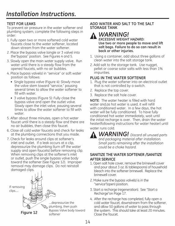
7. Check for leaks around clips at softener’s inlet and outlet. If a leak occurs at a clip, depressurize the plumbing (turn off the water supply and open faucets) before removing clip. When removing clips at the softener’s inlet or outlet, push the single bypass valve body toward the softener (See Figure 12). Improper removal may damage clips. Do not reinstall damaged clips.
ADD WATER AND SALT TO THE SALT STORAGE TANK
WARNING! EXCESSIVE WEIGHT HAZARD:Use two or more people to move and lift salt bags. Failure to do so can result in back or other injuries.
1. Using a container, add about three gallons of clean water into the salt storage tank.
2. Add salt to the storage tank. Use nugget, pellet or coarse solar salts with less than 1% impurities.
PLUG IN THE WATER SOFTENER1. Plug the water softener into an electrical outlet
that is not controlled by a switch.2. Replace the top cover.3. Replace the salt hole cover.NOTE: The water heater is filled with hard water and,as hot water is used, it will refill with conditioned water. In a few days, the hot water will be fully conditioned. To have fully conditioned hot water immediately, wait until the initial recharge is over. Then, drain the water heater(following instructions for water heater) until water runs cold.
SANITIZE THE WATER SOFTENER /SANITIZE AFTER SERVICE1. Open salt hole cover, remove the brinewell cover
and pour about 3 oz. (6 tablespoons) of household bleach into the softener brinewell. Replace the brinewell cover.
2. Make sure the bypass valve(s) is in the “service”(open) position.
3. Start a recharge (regeneration). See “Start a Recharge”on Page 17.
4. After the recharge has completed, fully open a cold water faucet, downstream from the softener, and allow 50 gallons of water to pass through the system. This should take at least 20 minutes. Close the faucet.
....depressurize the plumbing, then push Bypass Valve body toward softener
If removing clips.....
Figure 12
WARNING! Discard all unused parts and packaging material after installation. Small parts remaining after the installation could be a choke hazard.
2828
Exploded View.
8
7
6
5
11
16
146
28
5
999
29
4
12
213
3
7
8
9
10
56
56
17
19
20
22
23
23
24
30
26
29
Exploded View.
Cross-section View
Seal
Wear Strip
124
109
110
111
112
113
114
116
115
117
118 120
119
146
106
105103
130
107
108
130
121
147
152
122
123130
130
132
136
138
140
141
145
143
152
151
30
Parts List.
REF. NO. GE PART NO. PART DESCRIPTION (01)
BACK COVER, ELECTRONICS 1
0009 RESIN, 1 CU. FT. 1 1
POWER CORD 1
WITH LABEL 1
0020 COVER, BRINEWELL 1 0022 BRINEWELL 1 0023 1
0026 1
0056 1
, #10 - 14 x 2” 5 0106 COVER, VALVE 1
WASHER WAVE 1
0109 1 1
GXSF30V
31
Parts List.
REF. NO. GE PART NO. PART DESCRIPTION (01)
0113 1 0114 GASKET, NOZZLE/VENT 1 0115 1
NUT FERRULE 1
2
0124 NOZZLE/VENTURI ASM. 1 SEAL KIT 1
0132 1
0138 MOTOR MOUNT 1 0140 MOTOR 1 0141 SCREW, #6-19 x 1-3/8 2