BEHAVIOUR OF GFRP RETROFITTEDRECTANGULAR RC BEAMS WITH SMALL WEB OPENINGS UNDER TORSION: EXPERIMENTAL STUDY MANDALA VENUGOPAL Department of Civil Engineering National Institute of Technology, Rourkela Rourkela-769 008, Odisha, India
Transcript
BEHAVIOUR OF GFRP RETROFITTEDRECTANGULAR
RC BEAMS WITH SMALL WEB OPENINGS UNDER
TORSION: EXPERIMENTAL STUDY
MANDALA VENUGOPAL
Department of Civil Engineering National Institute of Technology, Rourkela Rourkela-769 008, Odisha, India
BEHAVIOUR OF GFRP RETROFITTED RECTANGULAR
RC BEAMS WITH SMALL WEB OPENINGS UNDER
TORSION: EXPERIMENTAL STUDY
A THESIS SUBMITTED IN PARTIAL FULFILMENT
OF THE REQUIREMENTS FOR THE DEGREE OF
Master of Technology
In
Structural Engineering By
MANDALA VENUGOPAL
(Roll No. 212CE2048)
DEPARTMENT OF CIVIL ENGINEERING
NATIONAL INSTITUTE OF TECHNOLOGY, ROURKELA
ROURKELA – 769 008, ODISHA, INDIA
BEHAVIOUR OF GFRP RETROFITTED RECTANGULAR
RC BEAMS WITH SMALL WEB OPENINGS UNDER
TORSION: EXPERIMENTAL STUDY
A THESIS SUBMITTED IN PARTIAL FULFILMENT
OF THE REQUIREMENTS FOR THE DEGREE OF
Master of Technology
In
Structural Engineering By
MANDALA VENUGOPAL
(212CE2048)
UNDERGUIDENCE OF
Prof ASHA PATEL
DEPARTMENT OF CIVIL ENGINEERING
NATIONAL INSTITUTE OF TECHNOLOGY, ROURKELA
ROURKELA – 769 008, ODISHA, INDIA
June 2014
Department of Civil Engineering National Institute of Technology, Rourkela
Rourkela – 769 008, Odisha, India
CERTIFICATE
This is to certify that the Thesis Report entitled “BEHAVIOUR OF GFRP RETROFITTED
RECTANGULAR RC BEAMS WITH SMALL WEB OPENINGS UNDER TORSION:
EXPERIMENTAL STUDY”, submitted by Mr. MANDALA VENUGOPAL bearing Roll no.
212CE2048 in partial fulfillment of the requirements for the award of Master of Technology in
Civil Engineering with specialization in “Structural Engineering” during session 2012-2014 at
National Institute of Technology, Rourkela is an authentic work carried out by him under my
supervision and guidance.
To the best of my knowledge, the matter embodied in the thesis has not been submitted to any
other university/institute for the award of any Degree or Diploma.
Place: Rourkela Prof. ASHA PATEL
Date: - Dept. of Civil Engineering
National Institute of Technology
Rourkela – 769008
i
ABSTRACT Provision of utility and service ducts are important part of modern building construction. To
facilitate fast and uninterrupted progress the layout of these ducts are planned in advance.
Their positions are decided considering the head room provisions in buildings, aesthetic look
etc. without jeopardizing the strength,stability and serviceability of the structures. To fulfil
these aspects many times ducts have to pass through main load bearing elements like beams.
Web openings in a beam adversely affect its strength and stiffness resulting in excessive
deflections which may lead to unpleasant appearance and the collapse of the structure.
Therefore, such beams are required to strengthen to restore their strength. The newly
developed technique of jacketing the deficit beam with layers of Fiber Reinforced Polymer
has proven to be very efficient in restoring and increasing the strength of the beams.
Since 1980 extensive research has been carried out on beams with rectangular and circular
openings under the most commonly encountered loading case of shear and flexure. The
behavior of beams with openings under torsion and its combination with shear and flexure
has not been explored much.
Hence the aim of the present work is to explore the behavior of rectangular RCC beams with
small circular and rectangular openings under torsion. The torsional capacity of beams with
openings are extracted experimentally .The study is extended by retrofitting the beams with
four layers of bidirectional woven GFRP fabric applied following three different
orientations scheme 90/90/90/90 ,45/45/45/45 and 90/45/90/45. The restoring torsion
capacity, crack patterns are observed.
The experimentally found torsion moment is compared with values calculated from modified
ACI code torsion equation proposed by Mansur, M.A. and Hasnat3 and found to be in good
agreement.The retrofitting scheme with GFRP layer orientation 90/45/90/45 proved to be best
scheme by providing maximum restoring torsion capacity and better ductility.
ii
ACKNOWLEDGEMENT
The satisfaction and euphoria on successful completion of any task would be incomplete without
the mention of the people who made it possible whose constant guidance and encouragement
crowned out effort with success.
I would like to express my heartfelt gratitude to my esteemed supervisor, Prof Asha Patel for her
technical guidance, valuable suggestions, and encouragement throughout the experimental and
theoretical study and in preparing this thesis. It has been an honour to work under Prof.Asha
Patel, whose expertise and discernment were key in the completion of this project.
I am grateful to the Dept. of Civil Engineering, NIT ROURKELA, for giving me the
opportunity to execute this project, which is an integral part of the curriculum in
M.Techprogramme at the National Institute of Technology, Rourkela.
Many thanks to my friends who are directly or indirectly helped me in my project work for their
generous contribution towards enriching the quality of the work. I would also express my
obligations to Mr.S.K.Sethi, Mr.R.Lugun&Mr.Sushil, Laboratory team members of Department
of Civil Engineering, NIT, Rourkela and academic staffs of this department for their extended
cooperation.
This acknowledgement would not be complete without expressing my sincere gratitude to my
parents for their love, patience, encouragement, and understanding which are the source of my
motivation and inspiration throughout my work. Finally I would like to dedicate my work and
CHAPTER 6 CONCLUSION AND RECOMMENDATIONS…………………………42
CHAPTER 7 REFERENCES……………………………………………………………..43
v
LIST OF FIGURES:-
S.NO
FIGURE
PAGE
NO.
1.1 Opening In The Beam 1
3.1 Detailing of reinforcement 8
3.2 a)GFRP Fabrics in [90/90] b)GFRP Fabrics in [45/45] 9
3.3 Roller used to remove air bubbles 9
3.4 Casting of the beam view 10
3.5 Form work 11
3.6 Setup of loading 12
3.7 B.M, S.F, Torsional Moment Diagram 12
4.1 a)Setup of the CB b)crack pattern in CB 13
4.2 a)Setup of the BSCO b)crack pattern in BSCO 15
4.3 a)Setup of the BTCO b)crack pattern in BTCO 17
4.4 a)crack pattern in BSRO b)crack pattern on top face of BSRO 19
4.5 a)Setup of the BTRO b)crack pattern on one face of BTRO
c)crack pattern on other face of BTRO
21
4.6 a)Setup of the BTCOG1 b) crack pattern on one face of BTCOG1
c)crack pattern on other face of BTCOG1
23
4.7 a)Setup of the BTCOG2 b) crack pattern on one face of BTCOG2
c)crack pattern on other face of BTCOG2
25
4.8 a)Setup of the BTCOG3 b) crack pattern on one face of BTCOG3
c) crack pattern on other face of BTCOG3
27
4.9 a)Setup of the BTROG1 b) crack pattern on one face of BTROG1
b) crack pattern on other face of BTROG1
29
4.10 a)Setup of the BTROG2 b) crack pattern on one face of BTROG2
b) crack pattern on other face of BTROG2
31
4.11 a)Setup of the BTROG3 b) crack pattern on one face of BTROG3
b) crack pattern on other face of BTROG3
33
vi
LIST OF GRAPHS:-
S.NO LIST OF GRAPHS PAGE NO
4.1 Torsional Moment VS Angle of Twist for CB 14
4.2 Torsional Moment VS Angle of Twist for BSCO 16
4.3 Torsional Moment VS Angle of Twist for BTCO 18
4.4 Torsional Moment VS Angle of Twist for BSRO 20
4.5 Torsional Moment VS Angle of Twist for BTRO 22
4.6 Torsional Moment VS Angle of Twist for BTCOG1 24
4.7 Torsional Moment VS Angle of Twist for BTCOG2 26
4.8 Torsional Moment VS Angle of Twist for BTROG1 28
4.9 Torsional Moment VS Angle of Twist for BTROG2 30
4.10 Torsional Moment VS Angle of Twist for BTCOG3 32
4.11 Torsional Moment VS Angle of Twist for BTROG3 34
4.12 Comparisons of beams CB,BSCO,BSRO 37
4.13 Comparisons of beams CB,BSCO,BTCO 37
4.14 Comparisons of beams CB,BSRO,BTRO 38
4.15 Comparisons of beams BSCO,BSCOG1,BSCOG2,BSCOG3 38
4.16 Comparisons of beams BTRO,BTROG1,BTROG2,BTROG3 39
4.17 Comparisons of beamsBTCOG3,BTROG3 39
vii
LIST OF TABLES:-
S.NO TABLE PAGE
NO
3.1 Properties of Concrete after 28 days 8
3.2 Tensile Strength of Reinforcing steel bars 9
3.3 Tensile Property of GFRP Fabric 9
4.1 Torsional Moment Vs Angle ofTwist For CB 14
4.2 Torsional Moment Vs Angle of Twist For BSCO 16
4.3 Torsional Moment Vs Angle of Twist For BTCO 18
4.4 Torsional Moment Vs Angle of Twist For BSRO 20
4.5 Torsional Moment Vs Angle of Twist For BTRO 22
4.6 Torsional Moment Vs Angle of Twist For BTCOG1 24
4.7 Torsional Moment Vs Angle of Twist For BTCOG2 26
4.8 Torsional Moment Vs Angle of Twist For BTCOG3 28
4.9 Torsional Moment Vs Angle of Twist For BTROG1 30
4.10 Torsional Moment Vs Angle of Twist For BTROG2 32
4.11 Torsional Moment Vs Angle of Twist For BTROG3 34
4.12 Percentage Reduction of All Beam 35
4.13 Percentage increase of all Circular Beams 36
4.14 Percentage Increase of all Rectangular Beam 36
5.1 Comparison Of Experimental and Theoretical Torsional Moment of Circular And Rectangular Openings with ACI Code.
41
viii
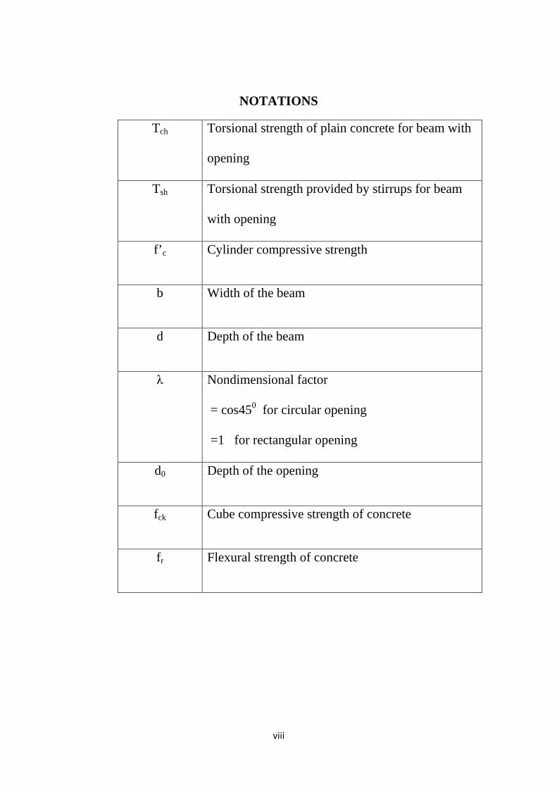
NOTATIONS
Tch Torsional strength of plain concrete for beam with
opening
Tsh Torsional strength provided by stirrups for beam
with opening
f’c Cylinder compressive strength
b Width of the beam
d Depth of the beam
λ Nondimensional factor
= cos450 for circular opening
=1 for rectangular opening
d0 Depth of the opening
fck Cube compressive strength of concrete
fr Flexural strength of concrete
ix
ACRONYMS AND ABBREVATIONS
ACI American Concrete Institute
IS Codes Indian Standard Codes
FRP Fiber Reinforced Polymer
GFRP Glass Fiber Reinforced Polymer
CFRP Carbon Fiber Reinforced Polymer
HYSD High-Yield Strength Deformed
CB Control beam
BSCO Beam with single circular opening
BTCO Beam with two circular opening
BSRO Beam with single rectangular opening
BTRO Beam with two rectangular opening
BTCOG1 Beam with two circular opening with GFRP[90/90]2
BTCOG2 Beam with two circular opening with GFRP[45/45]2
BTCOG3 Beam with two circular opening with GFRP[90/45]2
BTROG1 Beam with two rectangular opening GFRP[90/90]2
BTROG2 Beam with two rectangular opening GFRP[45/45]2
BTROG3 Beam with two rectangular opening GFRP[90/45]2
1
CHAPTER 1 INTRODUCTION
1.1 OVER VIEW
Nowadays openings in floor beams become necessary to provide service lines like water
supply lines, electricity, computer network ,air conditioning ducts etc to pass through in order
to save the story height specially in multi story buildings. Openings also reduce dead weight
of structures causing cost savings and systematically placed utility duct improve aesthetic
appearance.
The transverse openings through beams are a source of potential weakness. When the service
systems are pre-planned , and necessary layout of pipes and ducts are decided well in
advance then elements carrying them should be designed to ensure adequate strength and
serviceability by following the method described in the different codes.
FIG 1.1 Opening In The Beam(Vladimir Cervenka). However, this may not always be the case. While laying the ducts in a newly constructed
building, the Mechanical & Electrician contractor frequently comes up with the request to
drill an opening for the sake of simplifying the arrangement of pipes. When such a request
comes, the structural designer finds it difficult to give a decision because he would have to
take the risk of jeopardizing the safety and serviceability of the structure.
Another situation arises in an old building where concrete cores are taken for structural
assessment of the building. If the structure is to stay, then it is needed to repair it adequately
to restore the original level of safety and serviceability .
In the past, a lot of research had been carried out to study the behavior of reinforced concrete
beams with transverse openings. The investigations dealt with the behavior of reinforced
concrete beams with transverse rectangular and circular opening under different combinaions
of flexure, shear and torsion. Two types of transverse openings had been investigated, the
2
small and large opening.The classification is based on profile of opening. For rectangular
Opening if depth of opening is less than or equal to 0.25 time overall depth then it is called
small opening otherwise called Large Opening. For circular opening if diameter of the
opening is less than 40% of the overall depth of beam then called small opening ,otherwise
called Large Opening.
An opening creates discontinuity in the normal flow of stresses ,thus leading to stress
concentration at edges of the opening and leading to early cracking of concrete.To avoid this
special reinforcement enclosing the opening should be provided in the form of external or
internal reinforcement Internal reinforcements are steel bars provided along with the main
reinforcements during casting. External reinforcements are applied externally around opening
in the form of jacketing of composite materials like glass fibre or carbon fibre reinforced
polymer called GFRP or CFRP.
Fiber-reinforced polymer (FRP) is a composite material made of a polymer matrix reinforced
with fibers. The fibers are usually glass or carbon fiber,while the polymer is usually an
epoxy. Glass fiber fabrics are highly effective for strengthening of RC beams because of its
flexible nature and ease of handling and application, combined with high tensile strength
weight ratio and stiffness.
FRP sheets are currently being studied and applied around the world for the repair and
strengthening of structural concrete members. FRP composite materials are of great interest
because of their superior properties such as high specific stiffness and specific strength as
well as ease of installation when compared to other repairing materials. Also, the non-
corrosive and nonmagnetic nature of the materials along with its resistance to chemicals
makes FRP an excellent option for external reinforcement.
Research reveals that strengthening using FRP provides a substantial increase in post-
cracking stiffness and ultimate load carrying capacity of the members subjected to flexure,
shear and torsion.
Lot of investigations has been done to determine effect of openings on shear and flexural
behavior of RCC beam of different types like rectangular, T-beam, deep beam etc. . Very
few works have been done to find the effect of openings on torsional behavior of RCC beam.
Many research works are published on behavior of beams with opening retrofitted with
different types of FRP of different configurations and orientations under shear and flexure.
Very limited works are published for retrofitted beams with openings under torsion.
3
1.2 Objective Hence the aim of the present work is to experimentally study the effect of small openings of
rectangular and circular types on torsional behavior of rectangular RCC beam. The work is
further extended by retrofitting the beams by GFRP fabrics. The variables considered are
shape and number of openings on non-strengthen beams and orientation of GFRP fabrics in
retrofitted beams containing rectangular and circular openings. In the present work the ratio
torsion moment/ flexural moment adopted is one for all beams. The results obtained from
experiments are compared with the modified ACI torsion equation proposed by Mansur,
M.A. and Hasnat3.Good correlation is observed between experimental and observed values.
1.3Methodology
For the study eleven beams of same dimensions were cast in the Structural Engineering
Laboratory of Civil Engineering Department.
All beams were divided into two series. First series were cast with circular opening whereas
second were cast with rectangular openings of same cross sectional area. One beam without
web openings was also cast and treated as control beam.
Each series consisted of five beams; first beam had centrally located single opening and
remaining four were cast with two symmetrically located openings. The three beams with two
openings of both series were retrofitted with bi-directional GFRP fabric.
The retrofitting was done with four layers of GFRP fabric oriented in different directions.
The orientation scheme adopted were 90/90/90/90, 45/45/45/45 and 90/45/90/45.
All beams were tested under monotonically increasing static loads on both arms of projected
parts simultaneously, this arrangement transferred torsion to the middle part of the beam. All
beams were tested under torsion till failure.
During testing loads were applied in increments and at each increment deflections were
observed across the section to calculate twisting angle at different points on the beam.
During testing cracks formation and their propagation and inclinations were critically
observed. For retrofitted beams crack patterns and failure pattern were observed after
removing the GFRP from the beams.The experimentally determined values were compared
with analytical values obtained from modified torsion equation proposed by ACI Code.
4
CHAPTER 2
LITERATURE REVIEW
2.1 Literature Review On Torsional Strengtheningof RC Beams With Opening:-
SoroushAmiri, Reza Masoudnia and Ali Akbar Pabarja (2011) carried out study on
behavior of reinforced concrete beams with rectangular and circular openings and precast
beams with rectangular and circular openings was investigated. Then effects of the size and
location of the openings on the behavior of such beams are examined.
M.A. Mansur9 September (2006), gave a comprehensive overview on the analysis and
design of reinforced concrete beams contain transverse openings and subjected to a combined
bending and shear. Recognizing the differences in beam behaviors, circular and large
rectangular openings were treated separately. Practical situations of drilling openings in
existing beams are treated with special design consideration. Beams with multiple openings
were also briefly explained by author.
Ameli et al15. (2007) had experimentally investigated reinforced concrete beams subjected to
torsion and strengthened with an FRP wraps in a different configurations. Experimental
results showed that FRP wraps increase the ultimate torque of an fully wrapped beams
considerably and in addition enhancing ductility. They also provide a numerical study on the
retrofitted beams under torsion.
Abdallaa et al 17(2003) used fiber reinforced polymer (FRP) sheets to strengthen the opening
region in an experimental program’.
Thompson and Pessiki (2006) conducted an experimental study to investigate the behavior
of precast, pre-stressed inverted-tee girders with a large web openings under bending.
Mansur9 (1998) discussed the effects of introducing an transverse opening in the beams,
When no additional reinforcement was provided in the members above and below the
opening (chord members), tests conducted by Siao and Yap (1990) have shown that beams
fail prematurely by sudden formation of diagonal crack in the compression chord.
5
Somes and Corley4 (1974), defined small and large opening on the basis of experimental and
analytical study. The study was confined to circular opening. A circular opening was
considered as large opening when its diameter exceeds 0.25 times the depth of the web. .
Salam17 (1977) conducted an investigation on beams of rectangular cross section tested under
two symmetrical point loads. Moreover, Mansur et al (1991) an experimental carried out an
investigation on eight reinforced concrete continuous beams, each containing a large
transverse opening. Their study were showed that increase in depth of opening from 140
mm to 220 mm led to reduction in collapse load from 240 kN to 180 kN.
AbulHasnat and Aii A.Akhtanizzamam1 proposed a set of generalized strength equations
based on the skew bending model , developed to predict torsional strength and failure mode
of reinforced concrete beams with or without a small transverse opening. Twenty-four
rectangular reinforced-concrete beams containing a transverse opening of constant
dimensions were grouped into four different series and were tested under various
combinations of torsion, bending, and shear.
Hasnat et al (1993)11 had tested seventeen pre-stressed concrete beams without stirrups
containing transverse circular opening. In this research investigations were carried out on
beams having two openings of different diameters and subjected to various combinations of
torsion and bending.
Ghobarah18 et al. (2002) was conducted a experimental investigation on the improvement of
the torsional resistance of reinforced concrete beams using fiber-reinforced polymer (FRP)
fabric. A total of eleven beams was tested. Three beams was designated as an control
specimens and eight beams was strengthened by an FRP wrapping of different configuration
and tested. Both glass and carbon fibers was used in torsional resistance upgrade. The
effectiveness of an various wrapping configurations exhibited that fully wrapped beams
performed better than using strips. The 45° orientation of the fibers ensures that the material
is efficiently utilized.
Panchacharam and Belarbi19 (2002) had experimentally found that externally bonded
GFRP sheets can significantly increases both the cracking and ultimate torsional capacity of
RCC beams. The behaviour and performance of reinforced concrete member strengthened
with externally bonded Glass FRP (GFRP) sheets subjected to pure torsion was presented.
6
The variables considered in the experimental study include the fiber orientation, the number
of beam faces strengthened (three or four), the effect of number of FRP plies used, and the
influence of anchors in U-wrapped test beams. Experimental results revealed that externally
bonded GFRP sheets can significantly increases both the cracking and the ultimate torsional
capacity.
Ameliand Ronagh (2007); Hii and Al-Mahadi20 (2006); Rahal and Collins21 (1995).
Santhakumar et al. (2007) ,their works comprised of experimental and numerical study of
un-retrofitted and retrofitted solid reinforced concrete beams subjected to combined bending
and torsion. Different ratio between twisting moment and bending moment were considered.
The finite elements analysis by using ANSYS software were adopted for the study. Then the
study was extended to explore the behaviour of reinforced concrete beams retrofitted with
carbon fiber reinforced plastic composites with an 0/45and 0/90 fiber orientations. The study
revealed that the CFRP composites with 0/45 fiber orientations was more effective for
retrofitting an RC beams subjected to combined bending and torsion.
Zojaji and Kabir (2011) developed a new computational procedure to predict the full
torsional response of reinforced concrete beams strengthened with Fiber Reinforced Plastics
(FRPs), based on the Softened Membrane Model for Torsion (SMMT). To validate the
proposed analytical model, torque-twist curves was obtained from the theoretical approaches
are compared with experimental ones for both solid and hollow rectangular sections.
Rubinsky13 (1954) and Wines, J. C. et al., (1966) , had started research on FRP maerial and
its application on concrete structures.. Their pioneering work on bonded FRP system can be
credited to Meier (Meier 1987); this work led to an first on-site repair by the bonded FRP in
Switzerland (Meier and Kaiser (1991).Japan developed the first FRP applications for repair
of the concrete chimneys in an early 1980s..By 1997 more than 1500 concrete structures
worldwide have been strengthened with externally bonded FRP materials. Thereafter, many
FRP materials with different types of fibres have been developed.
7
CHAPTER 3
EXPERIMENTAL PROGRAM
3.1 MATERIAL PROPERTIES
3.1.1. Concrete
A mix of concrete of M20 grade is designed by using Portland Slag cement of Konarkbrand , locally available sand confirming to Zone III and 20 mm down size aggregate for a slump of 30mm. The mix is designed following IS 10262:2009 Code.
The proportion of design mix adopted for the experiment is 1:1.7:3.8 by weight and water cement ratio is taken as 0.6.
3.1.2 Reinforcing Steel HYSD Steel bars of Fe415 grade of 8mm,10mm,12mm and 16mm diameter are used for reinforcement. All bars are tested for Tensile strength and they comply with the code IS 1786-.1985
8
Table 3.2 Tensile Properties of Reinforcing steel bars
Diameter of Bar
mm
0.2% Proof
Stress
N/mm2
Ultimate Tensile
Strength
N/mm2
% Elongation
Remark
8
524 673.04 22.50
All bars are
complied with
IS 1786-1985
522 663.28 22.50
555 656.24 22.50
10
535 680.47 20.00
524 664.86 20.00
558 659.82 20.00
12
595 702.30 23.33
572 680.63 20.00
536 706.60 23.33
16
496 665.72 22.50
490 701.23 22.50
478 633.43 22.50
Fig 3-1 Reinforcement Detailing of Beams
3.1.3 Fiber Reinforced Polymer (FRP) Fiber reinforced materials with polymeric matrix (FRP) can be considered as composite,
They are heterogeneous, and anisotropic materials with a prevalent linear elastic behaviour
up to failure. Normally, Glass and Carbon fibres are used as reinforcing material for FRP. For
present study bidirectional woven GFRP fabric was used.
9
FIG 3.2 a)GFRP fabrics in [90/900] b) GFRP fabrics in [450/450]
3.1.4 Epoxy Resin Epoxy Resins was used to glue the layers of GFRP fabric and also used to stick the fabric to
concrete surface. The success of strengthening technique primarily depends on the
performance of the epoxy resin used for bonding of FRP to concrete surface. Numerous types
of epoxy resins with a wide range of mechanical properties are commercially available in the
market.
These epoxy resins are generally available in two parts, a resin and hardener. The resin and
hardener was used in present study are Araldite LY 556 and hardener HY 951 respectively.
Both the parts are mixed in 1:1 proportion.
To study the tensile properties of composite, standard coupons (250mm long x 25 mm wide)
were prepared by using different layers of GFRP and epoxy Resin. The tensile test was
performed on INSTRON UTM machine at the laboratory.
TABLE 3.3 TENSILE PROPERTY OF GFRP FABRIC
GFRP
Coupon
Thickness of
coupon mm
Ultimate stress
N/mm2
Ultimate load
in kN
Young’s modulus
N/mm2
2 layers 0.86 298 6.694 9839
4 layers 1.73 296 12.540 10040
10
Fig 3.3 Roller Used To Remove Air Bubbles
3.2 Casting of Specimens:- All beams are of same dimensions, having same reinforcements. All beams are designed to
fail in torsion hence no stirrups are provided except at each end to keep longitudinal
reinforcements in positions. The dimension of specimen beam is shown in Fig.
Fig 3.4 Casting ofthe Beam View
Beam was cast with circular/rectangular moulds to provide the opening in the transverse
direction. These moulds were removed after 24 hours. Beam was removed from the mould
next day and watered and covered with damped jute bags for curing for 28 days. Along with
beam, standard specimens to determined properties of concrete, these include three no. of
cubes (150mmx150mmx150mm), cylinders (150mm dia x300mm) and prisms
(100mmx100mmx500mm).They were tested after 28 days for cubical compressive strength
fck, cylindrical compressive strength fc , modulus of rupture frand split tensile strength.
Three beams in each cases were strengthen by sticking four layers of GFRP fabric in different
orientations as per the scheme. While sticking the fabrics care had been taken to remove the
11
air pockets within the layers. After sticking fabrics beams were left for 48 hours to allow the
composite to set.
3.3 STRENGTHENING OF BEAMS To stick the GFRP fabric , the concrete surface is made rough using a coarse sand paper and
then cleaned with an air blower to remove all dirt and debris. The mixing of resin and
hardener are carried out in a plastic mug container. The GFRP fabric are cut according to the
size . A layer of epoxy resin was uniformly applied to the concrete surface of beam and a
layer of GFRP fabric in pre decided direction is glued to the concrete surface, once it is
properly placed further epoxy resin is applied and the next layer of GFRP fabric in required
direction is glued to the beam. The procedure is adopted to stick all layers. After application
of each layer ,a roller is used to remove air bubbles entrapped at the epoxy/concrete or an
epoxy / fabric interface .During hardening of the epoxy, a constant uniform pressure is
applied to the composite fabric surface in order to extrude the excess epoxy resin and to
ensure good contact between the epoxy, the concrete and the fabric. For proper bonding, this
operation must be carried out at a room temperature.
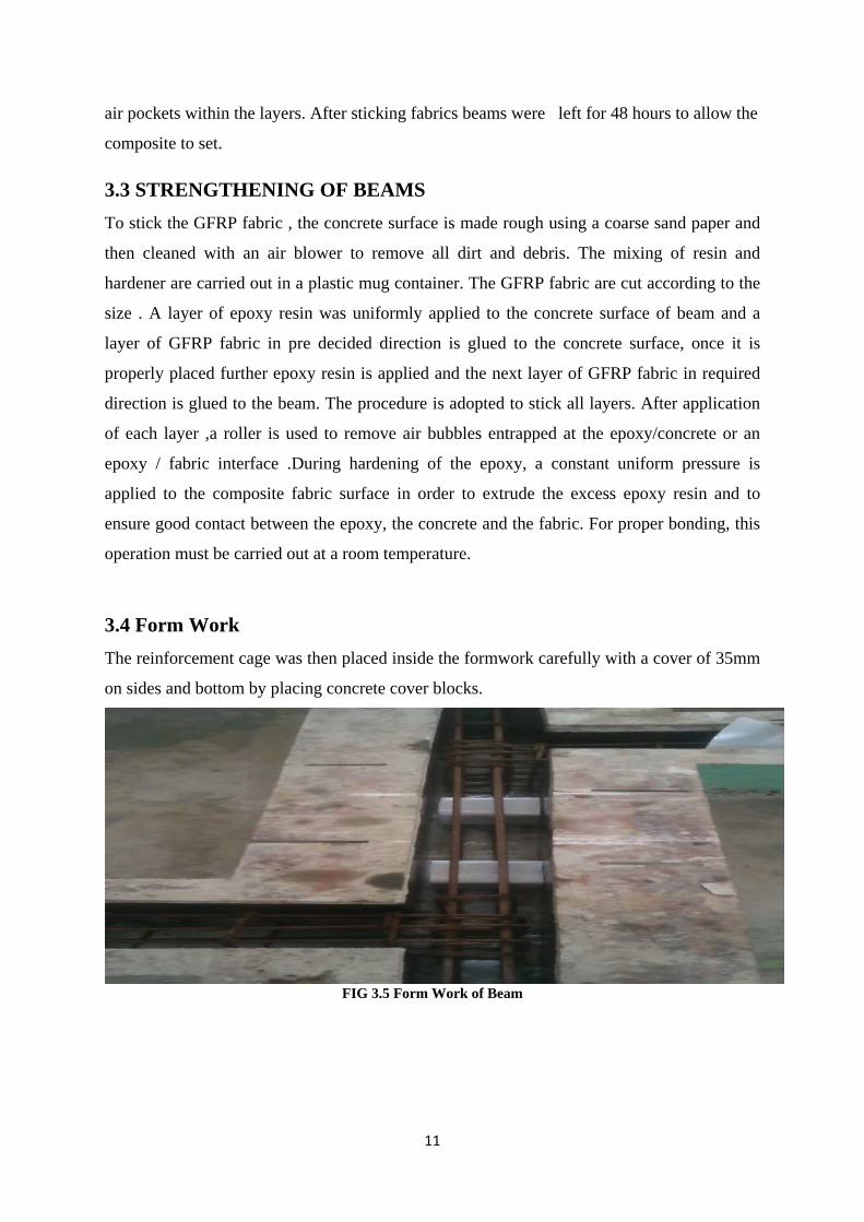
3.4 Form Work The reinforcement cage was then placed inside the formwork carefully with a cover of 35mm
on sides and bottom by placing concrete cover blocks.
FIG 3.5 Form Work of Beam
12
3.5. EXPERIMENTAL SETUP All beams were tested under monotonically increasing static loads on both arms of projected
parts simultaneously, this arrangement transferred torsion to the middle part of the beam of
0.8 m length. The beams were tested under torsion till failure. During testing loads were
applied in increments and at each increment deflections were observed across the section to
calculate twisting angle at different points on the beam. During testing cracks formation and
their propagation and inclinations were critically observed. For retrofitted beams crack
patterns and failure pattern were observed after removing the GFRP from the beams.
The standard specimens corresponds to the beam were tested to determine cubical and
cylindrical compressive strength and modulus of rupture of concrete.
Fig 3.6Experimental Set-up For Testing
FIG 3.7Shear Force,Bending Moment and Torsional Moment Diagrams
13
CHAPTER 4
RESULTS AND DISCUSSIONS
4.1 Testing Of Beams:-
Allthe eleven beams were tested till complete collapse. Two dial gauges were placed along
the width of a section to measure deflections in order to calculate angle of twisting moment at
the section. Such arrangements were made at sections along the span, below the centre of
openings and sections midway between opening and projecting arms. Demac gauges were
also fixed on one side vertical face of the beam to measure strains with the help of
mechanical strain gauge.Loads were applied in increments. At each increment dial gauges
readings and strain gauge readings were noted down. Simultaneously cracks were observed
and their propagations were carefully monitored till collapse occurred. The angle of
inclination of principal cracks formed was measured.
4.1.1 CONTROL BEAM (CB):-
Control beam was beam without opening. Load was applied on the two projected moment
arm of the beams which generated torsion in middle 0.8 m long span of the beam.. At each
increment of the load, deflections at L/3, L/2 and 2L/3 was observed and noted down with the
help of six nos. of dial gauges. At each section two dial gauges were fixed to measure the
displacement caused by twisting moment. The relative displacements divided by distance
between dial gauges gives angle of twist. Section at L/3 was taken as sec-1, section at middle
of beam as taken as sec-2, and section at 2L/3 was taken as section 3.The load at which the
first visible crack is developed is recorded as initial cracking load. Then the load is applied
till the complete failure of the beam.
FIG 4.1(a)Control Beam CB (b) Crack pattern in Control beam
14
The initial crack in the CB was appeared at 70KN, and the ultimate load failure of the
control beam was at 86KN and torsional moment was 33.54KN-M.A major diagonal crack
had formed making 450angles with horizontal.
TABLE 4.1 Torsional Moment Vs Angle of Twist for CB
GRAPH 4.1 Torsional moment Vs Angle of twist for CB.
05
10152025303540
0 0.1 0.2 0.3 0.4 0.5
Tors
iona
l Mom
ent(
kN-m
)
Angle of Twist(rad)
s1
s2
s3
Load
kN
Torsional Moment kN-m
Section 1 Section 2 Section 3 Remarks
Angle of twist( radians)
0 0 0 0 0
10 3.9 0.085 0.086 0.081
20 7.8 0.130 0.122 0.110
30 11.7 0.171 0.162 0.141
40 15.8 0.225 0.213 0.167
50 19.5 0.280 0.252 0.192
60 23.4 0.319 0.292 0.216
70 27.3 0.376 0.347 0.247 Initial crack appeared
80 31.2 0.441 0.446 0.270
86 33.54 Ultimate failure load
15
4.1.2 BEAM (BSCO):-
This was a Beam with Single Circular Opening at the centre. The diameter of opening was
100mm which as per the specifications are small opening. Extra reinforcement was not
provided at the opening in order to study the effect of opening in terms of load carrying
capacity. The experimental set up and method of testing was same as in previous case. Two
dial gauges were provided at centre of the hole across the width of the section.
FIG 4.2(a)Beam BSCO
FIG 4.2(b) Crack pattern in BSCO beam
The first crack initiated at load of 60 kN at edge of the opening .Two major cracks formed as
shown in the Fig. and propagated diagonally toward edges of the beam along with various
inclined cracks. This type of failure is called Frame Type failure. The beam failed at 78 kN
load i.e. at 30.42 kN-m torsional moment.It was observed that the cracks were appeared
making an angle 40º-50º with the main beam.. As compared to the control beam the
percentage reduction in loading was 9.30%.
16
TABLE 4.2 Torsional Moment Vs Angle of Twist forBSCO
GRAPH 4.2 Torsional moment Vs Angle of twist of BSCO
Since the reduction in torsional moment capacity for this beam was 9.3% only. It was decided to have two openings instead for better investigation.
GRAPH 4.4 Torsional moment Vs Angle of twist of BSRO
0
5
10
15
20
25
30
0 0.1 0.2 0.3 0.4 0.5 0.6
Tors
iona
l Mom
ent(
kN-m
)
Angle of Twist(rad)
s1
s2
s3
21
4.1.5 BEAM (BTRO):-
This was a Beam with Two Rectangular Openings symmetrically located. The size of
openings was 110mm x 72 mm . The experimental set up and method of testing was same as
in previous case. Sets of dial gauges were provided below centre of both openings hence four
sets of dial gauges were used for measuring twist angles.
FIG 4.5(a) BeamBTRO
FIG 4.5( b) Crack pattern on one face of BTRO
FIG 4.5(c) Crack pattern on another face of BTRO
22
The first crack started at load of 28kN. The crack pattern is shown in the Fig. One major diagonal crack formed across the one opening causing failure and spalling of concrete at bottomedge. Complete collapse occurred at 35 kN load i.e. at 13.6kNm torsional moment. The crack made an angle of 480 with the edge of the beam. The percentage reduction in strength was found to be 59.3%.
TABLE 4.5 Torsional Moment Vs Angle of Twist for BTRO
Load
kN
Torsional
Moment
kN-m
Section1
Section2
Section3
Section4
Remarks
0 0 0 0 0 0
10 3.9 0.35 0.36 0.37 0.35
20 7.8 0.58 0.59 0.65 0.55
30 11.7 0.62 0.72 0.93 0.83 Initial Crack at
28kN
35 Ultimate Load
Failure at 35kN
GRAPH 4.5 Torsional moment Vs Angle of twist of BTRO
The remaining 6 beams (with two openings), threefrom each series are retrofitted with GFRP
fabrics. For all beams four layers of Bi-directional GFRP fabric were used. All beams were
fully U-jacketed with four layers of GFRP. In each case orientation of layer of fabric were
different. The layers orientation considered were (90/90/90/90), (45/45/45/45) and
(90/45/90/45). The GFRP were not applied inside the opening. All beams were observed for
de-bonding and fracture type of failure. This will help to theoretical analysis of the beams and
to validate the experimentally found results.
02468
101214
0 0.2 0.4 0.6 0.8 1Tors
iona
l mom
ent(
kN-m
)
Angle of Twist(rad)
sec1
sec2
sec3
sec4
23
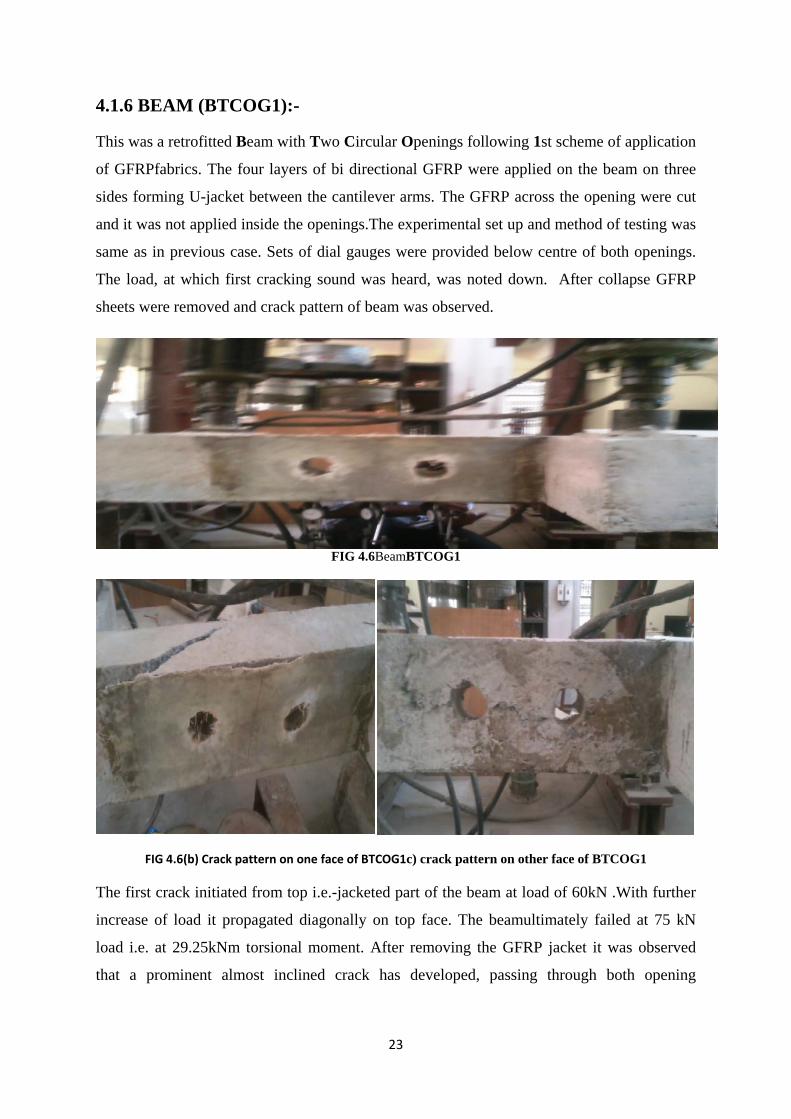
4.1.6 BEAM (BTCOG1):-
This was a retrofitted Beam with Two Circular Openings following 1st scheme of application
of GFRPfabrics. The four layers of bi directional GFRP were applied on the beam on three
sides forming U-jacket between the cantilever arms. The GFRP across the opening were cut
and it was not applied inside the openings.The experimental set up and method of testing was
same as in previous case. Sets of dial gauges were provided below centre of both openings.
The load, at which first cracking sound was heard, was noted down. After collapse GFRP
sheets were removed and crack pattern of beam was observed.
FIG 4.6BeamBTCOG1
FIG 4.6(b) Crack pattern on one face of BTCOG1c) crack pattern on other face of BTCOG1
The first crack initiated from top i.e.-jacketed part of the beam at load of 60kN .With further
increase of load it propagated diagonally on top face. The beamultimately failed at 75 kN
load i.e. at 29.25kNm torsional moment. After removing the GFRP jacket it was observed
that a prominent almost inclined crack has developed, passing through both opening
24
andmaking an angle 500. The increase in torsional capacity was found to be 9.3% with
respect to corresponding non retrofitted beam BTCO.
TABLE 4.6 Torsional Moment Vs Angle of Twist for BTCOG1
GRAPH 4.6 Torsional moment Vs Angle of twist of BTCOG1
0
5
10
15
20
25
30
35
0 0.2 0.4 0.6 0.8 1
Tors
iona
l mom
ent
Angle Twist
sec1
sec2
sec3
Load
kN
Torsional
moment
kN-m
Section 1
Section 2
Section 3
Remarks
0 0 0 0 0
10 3.9 0.06 0.03 0.06
20 7.8 0.13 0.11 0.13
30 11.7 0.22 0.17 0.25
40 15.8 0.48 0.30 0.40
50 19.5 0.52 0.37 0.47
60 23.4 0.65 0.52 0.64 Initial crack at 60kn
70 27.3 0.87 0.75 0.91
75
29.25
Ultimate failure at
75kn
25
4.1.7 BEAM (BTCOG2):-
This was a retrofitted Beam with Two Circular Openings following 2nd scheme of
application of GFRP fabrics i.e. (45/45/45/45/45). The layers made 450 with longitudinal axis
of beam. The method of application of GFRP fabric was same. The experimental set up and
method of testing was same as in previous case. After collapse GFRP sheets were removed
and crack pattern of beam was observed.
FIG 4.7(a)Beam BTCOG2
FIG 4.7(b) Crack pattern on one face of BTCOG2
FIG 4.7(c) Crack pattern on other faceof BTCOG2
26
In this case also major crack had initiated from top i.e.un- strengthened part of the beam at 70
KN load. The beam failed at 85 kN load i.e. at 33.15kNm torsional moment.Removal of
GFRP showed Frame type of failure. It was observed that the cracks were appeared making
an angle 450 with the main beam. 20 % increase in torsional moment capacity was observed. TABLE 4.7 Torsional Moment Vs Angle of Twist for BTCOG2
Load
kN
Torsional
moment
kN-m
Section 1
Section 2
Section 3
Remarks
0 0 0 0 0
10 3.9 0.22 0.22 0.14
20 7.8 0.33 0.34 0.24
30 11.7 0.50 0.48 0.42
40 15.8 0.70 0.67 0.57
50 19.5 0.93 0.85 0.71
60 23.4 1.19 1.21 1.08
70 27.3 1.45 1.50 1.48 Initial crack 70kN
80 31.2 1.60 1.62 1.63
85 Ultimate load 85kN
GRAPH 4.7 Torsional moment Vs Angle of twist of BTCOG2
0
5
10
15
20
25
30
35
0 0.5 1 1.5 2
Tors
iona
l mom
ent(
kN-m
)
Angle of twist(rad)
sec 1
sec 2
sec 3
27
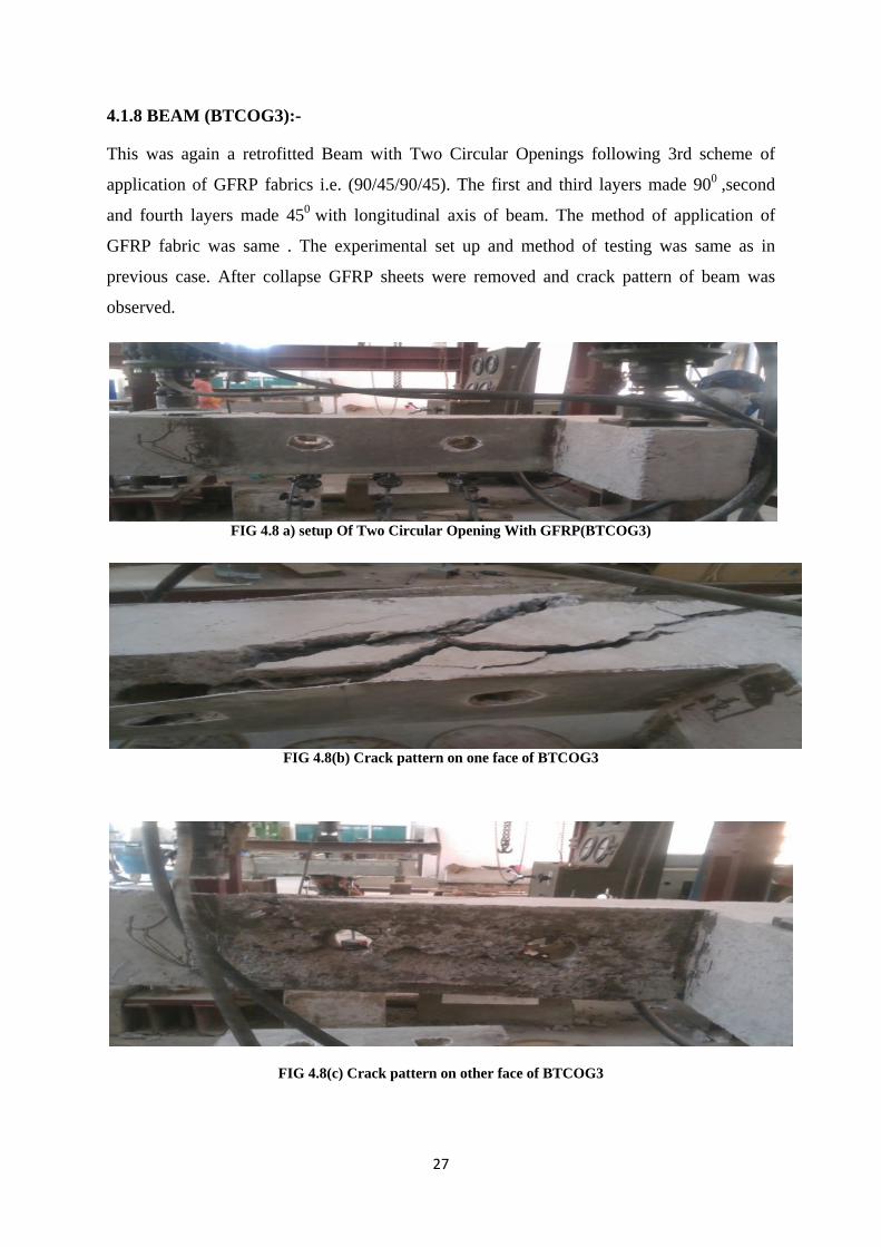
4.1.8 BEAM (BTCOG3):-
This was again a retrofitted Beam with Two Circular Openings following 3rd scheme of
application of GFRP fabrics i.e. (90/45/90/45). The first and third layers made 900 ,second
and fourth layers made 450 with longitudinal axis of beam. The method of application of
GFRP fabric was same . The experimental set up and method of testing was same as in
previous case. After collapse GFRP sheets were removed and crack pattern of beam was
observed.
FIG 4.8 a) setup Of Two Circular Opening With GFRP(BTCOG3)
FIG 4.8(b) Crack pattern on one face of BTCOG3
FIG 4.8(c) Crack pattern on other face of BTCOG3
28
In this case also major crack had initiated from top i.e.un- strengthened part of the beam at
75kN load. The beam failed at 90 kN load i.e. at 35.1 kN-m torsional moment. Removal of
GFRP showed multiple cracks formation with spilling of concrete on vertical faces. It was
observed that the major cracks were appeared making an angle 550 with the main beam and
24.4 % increase in torsional moment capacity was observed. TABLE 4.8 Torsional Moment Vs Angle of Twist for BTCOG3
Load
kN
Torsional
moment
kN-m
ANGLE OF TWISTING
Section 1 Section 2 Section 3 Remarks
0 0 0 0 0
10 3.9 0.12 0.12 0.13
20 7.8 0.18 0.21 0.25
30 11.7 0.29 0.30 0.33
40 15.6 0.39 0.40 0.46
50 19.5 0.51 0.52 0.60
60 23.4 0.63 0.64 0.74
70 27.3 0.82 0.79 0.99 Initial crack 75kN
80 31.2 1.02 0.98 1.31
90 35.1 Ultimate load 90kN
GRAPH 4.8 Torsional moment Vs angle of twist of BTCOG3
0
5
10
15
20
25
30
35
40
0 0.2 0.4 0.6 0.8 1 1.2 1.4
Tors
iona
l mom
ent(
kN-m
)
Angle of twist(rad)
sec 1
sec 2
sec 3
29
4.1.9 BEAM(BTROG1):-
This was a retrofitted Beam with Two Rectangular Openings following 1st scheme of
application of GFRP fabrics i.e. 90/90/90/90. The method of application of GFRP fabric was
same. The experimental set up and method of testing was same as in previous cases. Sets of
dial gauges were provided below centre of both openings. The load at which first crack
appeared was noted down. After collapse GFRP sheets were removed and crack pattern of
beam was observed.
Similar to previous cases for retrofitted beams in this case also initial crack at 60 kN load was
observed at top which was not covered with GFRP fabric. The beam failed at 70 kN load i.e.
at 27.3 kNm torsional moment. Removal of GFRP showed beam type of failure. It was
observed that the major cracks made an angle 480 with the longitudinal axis of main beam
and 50 % increase in torsional moment capacity was obtained.
FIG 4.9(a)Beam BTROG1
FIG 4.9(b) Crack pattern on one face of BTROG1
30
FIG 4.8(c) Crack pattern on other side of BTROG1
TABLE 4.9 Torsional Moment Vs Angle of Twist for BTROG1
Load
kN
Torsional
moment kN-m
Section 1
Section 2
Section 3
Remarks
0 0 0 0 0
10 3.9 0.11 0.13 0.12
20 7.8 0.25 0.27 0.26
30 11.7 0.31 0.35 0.33
40 15.6 0.42 0.45 0.44
50 19.5 0.64 0.66 0.64 Initial crack 50kN
60 23.4 0.85 0.87 0.92
70 27.3 Ultimate load at
70kN
GRAPH 4.9 Torsional moment Vs Angle of twist of BTROG1
0
5
10
15
20
25
30
0 0.2 0.4 0.6 0.8 1
Tors
iona
l mom
ent(
kN-m
)
Angle of twist(rad)
section 1
section 2
section 3
31
4.1.10BEAM (BTROG2):-
This was a retrofitted Beam with Two Rectangular Openings following 2nd scheme of
application of GFRP fabrics i.e., (45/45/45/45/45). The layers made 450 with longitudinal axis
of beam. The method of application of GFRP fabric was same. The experimental set up and
method of testing was same as in previous case. After collapse GFRP sheets were removed
and crack pattern of beam was observed.
FIG 4.10Setup of the Beam with GFRP BTROG2
FIG 4.10(b) Crack pattern on one face of BTROG2
FIG 4.10(c) Crack pattern on other face of BTROG2
The first crack was visible at 65 KN load on top face of the beam. The beam failed at 80 KN
load i.e. at 31.2 kink torsional moment. Removal of GFRP showed beam type of failure on
32
side accompanied by crushing of concrete. It was observed that the major crack made an
angle 500 with the longitudinal axis of main beam and 56.25 % increase in torsional moment
capacity was obtained.
TABLE 4.10 Torsional Moment vs Angle of Twist for BTROG2:-
Load
kN
Torsional
moment kN-m
Section 1
Section 2
Section 3
Remarks
0 0 0 0 0
10 3.9 0.17 0.21 0.21
20 7.8 0.34 0.37 0.33
30 11.7 0.53 0.54 0.51
40 15.6 0.69 0.69 0.66
50 19.5 0.91 0.89 0.85
60 23.4 1.15 1.11 1.02 Initial crack 60kN
70 27.3 1.26 1.22 1.18
80 31.2 Ultimate load 80kN
GRAPH 4.10 Torsional momentVs Angle of twist of BTROG2
0
5
10
15
20
25
30
35
0 0.2 0.4 0.6 0.8 1 1.2 1.4
Tors
iona
l mom
ent(
kN-m
)
Angle of twist(rad)
sec 1
sec 2
sec 3
33
4.1.11 BEAM (BTROG3):-
In two rectangular opening beam, GFRP sheet is applied for strengthening the beam under
torsional loading .total four layers were applied in bidirectional [90/45/90/45] in this beam
also one layer is applied in 900bidirectionally and another was in 450bidirectionallyfor whole
opening portion of the beam one after another layer is applied as shown in figure and the
opening dimensions is same as in beam BTRO. Beam BTROG3 is two circular opening in a
beam with GFRP as shown in fig. This beam was casted and tested to study effect of the
beam with two circular opening in a beam with torsional loading. Strengthening was done
with GFRP of 4 layers in [90/45]2 to this beam.
FIG 4.11(a)Beamwith GFRP (BTROG3)
b) Crack pattern on one face of BTROG3
FIG 4.11(c) Crack pattern on other face of BTROG3
34
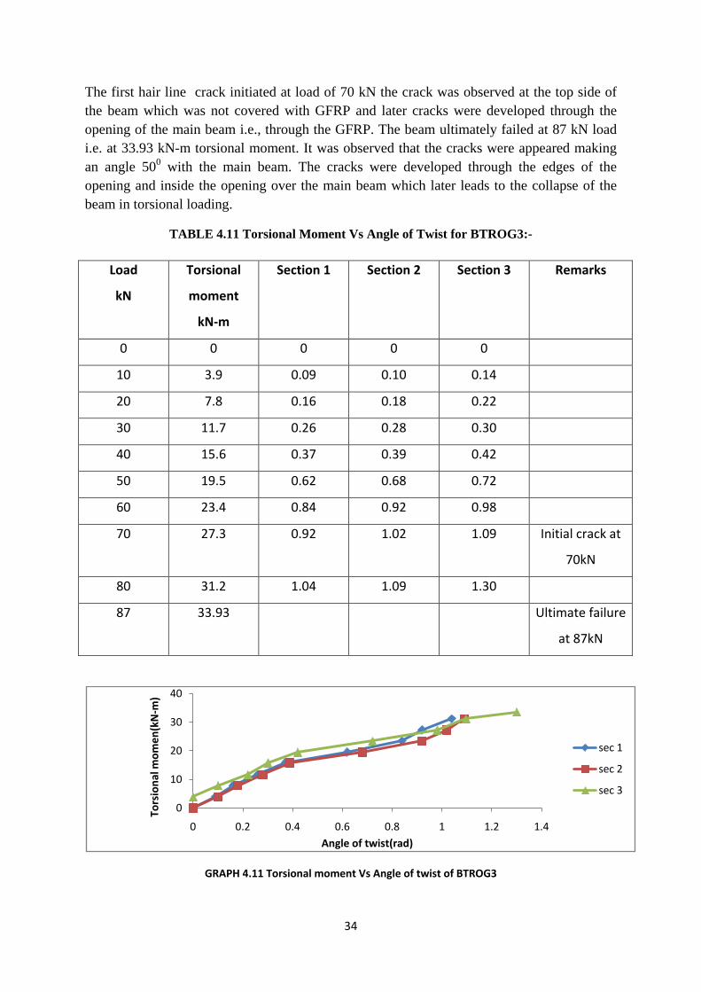
The first hair line crack initiated at load of 70 kN the crack was observed at the top side of the beam which was not covered with GFRP and later cracks were developed through the opening of the main beam i.e., through the GFRP. The beam ultimately failed at 87 kN load i.e. at 33.93 kN-m torsional moment. It was observed that the cracks were appeared making an angle 500 with the main beam. The cracks were developed through the edges of the opening and inside the opening over the main beam which later leads to the collapse of the beam in torsional loading.
TABLE 4.11 Torsional Moment Vs Angle of Twist for BTROG3:-
Load
kN
Torsional
moment
kN-m
Section 1 Section 2 Section 3 Remarks
0 0 0 0 0
10 3.9 0.09 0.10 0.14
20 7.8 0.16 0.18 0.22
30 11.7 0.26 0.28 0.30
40 15.6 0.37 0.39 0.42
50 19.5 0.62 0.68 0.72
60 23.4 0.84 0.92 0.98
70 27.3 0.92 1.02 1.09 Initial crack at
70kN
80 31.2 1.04 1.09 1.30
87 33.93 Ultimate failure
at 87kN
GRAPH 4.11 Torsional moment Vs Angle of twist of BTROG3
4.2.1 Comparisons of Un-strengthen beams ( CB,BSCO,BSRO)
GRAPH 4.12 Comparisons for beams CB, BSCO, and BSRO
The comparison of beams with single circular and rectangular with control beam exhibited
that there is decrease in torsional moment capacity of beams. The reduction is more for
rectangular opening. This may be due to more stress concentration at corners of the
rectangular opening. Due to reduction in stiffness in both beams with openings BSCO &
BSRO more deflection were observed than control beam.
4.2.2 Comparisons of Un-strengthen beams with circular opening
GRAPH 4.13 Comparisons of beams CB, BSCO, and BTCO
0
5
10
15
20
25
30
35
40
0 0.5 1
Tors
iona
l mom
ent
Angle of twist
CB
BSCO
BSRO
8678
66
0102030405060708090
100
CB BSCO BSRO
LOAD
KN
BEAM NAMES
CB
BSCO
BSRO
0
5
10
15
20
25
30
35
40
0 0.5 1 1.5
Tors
iona
l mom
ent
Angle of twist
CB
BSCO
BTCO
8678
68
0102030405060708090
100
CB BSCO BTCO
LOAD
KN
BEAM NAMES
CB
BSCO
BTCO
38
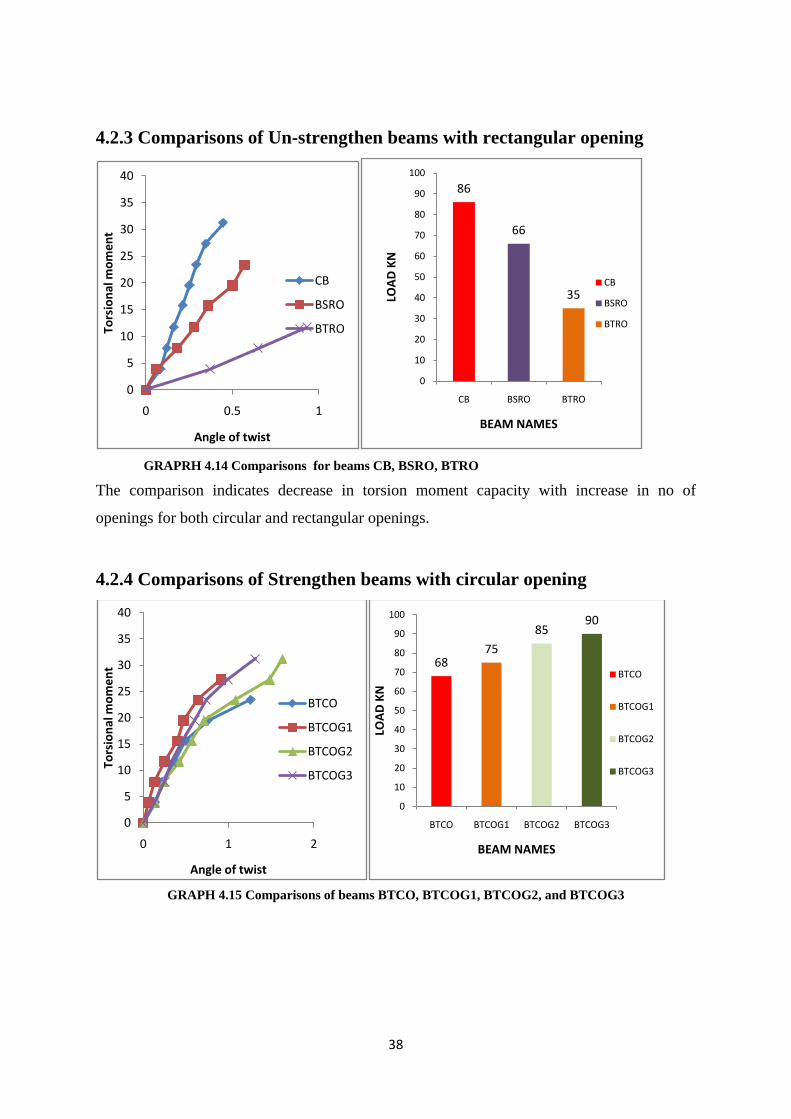
4.2.3 Comparisons of Un-strengthen beams with rectangular opening
GRAPRH 4.14 Comparisons for beams CB, BSRO, BTRO
The comparison indicates decrease in torsion moment capacity with increase in no of
openings for both circular and rectangular openings.
4.2.4 Comparisons of Strengthen beams with circular opening
GRAPH 4.15 Comparisons of beams BTCO, BTCOG1, BTCOG2, and BTCOG3
0
5
10
15
20
25
30
35
40
0 0.5 1
Tors
iona
l mom
ent
Angle of twist
CB
BSRO
BTRO
86
66
35
0
10
20
30
40
50
60
70
80
90
100
CB BSRO BTROLO
AD K
N
BEAM NAMES
CB
BSRO
BTRO
0
5
10
15
20
25
30
35
40
0 1 2
Tors
iona
l mom
ent
Angle of twist
BTCO
BTCOG1
BTCOG2
BTCOG3
6875
8590
0
10
20
30
40
50
60
70
80
90
100
BTCO BTCOG1 BTCOG2 BTCOG3
LOAD
KN
BEAM NAMES
BTCO
BTCOG1
BTCOG2
BTCOG3
39
4.2.5 Comparisons of Strengthen beams with rectangular opening
GRAPH 4.16 Comparisons of beams BTRO, BTROG1, BTROG2, and BTROG3
4.2.6Comparisons of Strengthen beams
GRAPH 4.17 Comparisons of beams BTCOG3 and BTROG3
The graphs indicate that U-jacketing the beams with GFRP fabric restore the torsion moment
capacity of beams with circular openings in order of 9.3% to 24.4% and beams with
rectangular opening in order of 50 % to 59.7% depending on the orientation of fibre in each
layer.
0
5
10
15
20
25
30
35
40
0 1 2
Tors
iona
l mom
ent(
kN-m
)
Angle of twist(rad)
BTRO
BTROG1
BTROG2
BTROG3
35
7080
87
0
10
20
30
40
50
60
70
80
90
100
BTRO BTROG1 BTROG2 BTROG3LO
AD K
N
BEAM NAMES
BTRO
BTROG1
BTROG2
BTROG3
0
5
10
15
20
25
30
35
0 0.5 1 1.5
Tors
iona
l mom
ent
Angle of twist
BTCOG3
BTROG3
8690 87
0
10
20
30
40
50
60
70
80
90
100
CB BTCOG3 BTROG3
LOAD
S KN
BEAM NAMES
CB
BTCOG3
BTROG3
40
The comparison showed that restoration of capacity is maximum for the case 90/45/90/45
scheme than in 45/45/45/45 scheme .It is least for 90/90/90/90 scheme.
The 450 fibre orientation scheme provided better option to regain andto increase the torsional
capacity of beams with openings.
Out of the three schemes considered 45/45/45/45 orientation scheme provide higher ductility.
Post cracking stiffness of the beam with 90/90/90/90 scheme is much higher than the
remaining two.
The orientation scheme 90/45/90/45 is best option for retrofitting the beam with openings
because it provides maximum restoring torsion capacity and considerable higher ductility.
41
CHAPTER 5
NUMERICAL STUDY
Themodified ACItorsion equation proposed Mansur, M.A. and Hasnat3by for a rectangular beam with circular and rectangular openings is
𝑇𝑇𝑇𝑇𝑇𝑇ℎ = 2�𝑓𝑓𝑇𝑇′𝑏𝑏2ℎ �1 − 𝜆𝜆d0h �
Tpch= Torsional strength of plain concrete
Where f’c= cylinder compressive strength b and h =width and depth of the beam.
λ = cos 450for a circular opening and1 for a rectangular opening.
d0 = Diameter of opening.
The torsional strength of a reinforced concrete beam with opening is
Th =Tch+Tsh
Tch= Torsional strength of plain concrete Tsh = Torsional strength provided by stirrups
In the present study stirrups were not provided ,hence this contribution is zero.
Th =Tch
Table 5.1Comparison on Experimental with Theoretical Torsional Moment of Circular and Rectangular Openings
The comparison of results indicate that the torsion strength is slightly overestimated for beams with circular openings and under estimated for beams with rectangular openings by using the modified ACI torsion equation proposed Mansur, M.A. and Hasnat3.