52
Bell System (Telephones) Ltd
| Date post: | 19-Jul-2018 |
| Category: |
Documents |
| Upload: | hoangthuan |
| View: | 221 times |
| Download: | 0 times |

Bell System (Telephones) Ltd


DAX Isolating Exchange System PD-059 Issue 3
ContentsIntroduction ................................................................. 1Operating Instructions................................................ 3
Keypad Operation............................................................................................ 3Conversing with a resident and entering a building ......................................... 3Tradesman/Coded Access Facility .................................................................. 4Multi-entrance Operation ................................................................................. 5
System Components................................................... 7DPX-LED Door Entrance Panel....................................................................... 7
Diagram 2 DPX-LED Door Panel.......................................................... 8LM10 Display Module ........................................................................... 9Model 61 Speech Unit........................................................................... 9
DAX Control Cabinet ....................................................................................... 9CTX64P Door Controller PCB............................................................... 9Diagram 3 DAX Control cabinet internal components......................... 10EXP64 System Expander PCB........................................................... 11RLX8 relay PCB.................................................................................. 11TS2000-BST Time-Clock Module ....................................................... 11CAB5 Power Supply ........................................................................... 12
Telephones.................................................................................................... 12Table 1 Compatible telephone models ............................................... 12
System Expansion......................................................................................... 13Custom Specifications for the DAX Control Cabinets .................................... 13Other System features................................................................................... 15
Lock Release ...................................................................................... 15Egress Button ..................................................................................... 15Tone Output........................................................................................ 15Door Open Indication. ......................................................................... 16
Cable Planning .......................................................... 17Important Safety Information ......................................................................... 20
Installation ................................................................. 21Fitting the Control cabinets............................................................................ 21Fitting the Entrance Panels............................................................................ 22Fitting the Telephones ................................................................................... 22
Testing and Commissioning .................................... 23Turning the system on for the first time ......................................................... 23Testing the Entrance Panel ........................................................................... 23System Programming .................................................................................... 23Testing the Telephones ................................................................................. 23Testing the Time-clock .................................................................................. 24Testing the system on battery standby .......................................................... 24

DAX Isolating Exchange System PD-059 Issue 3
Other Tests.................................................................................................... 24Display........................................................................................................... 25Speech Adjustment ....................................................................................... 25
Programming The Entrance Panels......................... 26Entering Program Mode ................................................................................ 26Selecting a Parameter ................................................................................... 26Changing a parameter................................................................................... 26Programmable parameters............................................................................ 27The TS2000-BST Time-Clock Module........................................................... 32
Test Mode................................................................... 33To enter Test Mode: ...................................................................................... 33To exit Test mode:......................................................................................... 33Using Test Mode from an Entrance Panel..................................................... 34Using Test Mode from a Door Controller PCB............................................... 34
Diagnostic LEDs........................................................ 35Troubleshooting ........................................................ 36Technical Specification............................................. 38Appendix .................................................................... 39
Table 4 System Expander DIP switch .......................................................... 40Table 4a Door open local/any feature............................................................ 40Table 4b Phone bank address....................................................................... 40Diagram 4 Entrance Connections.................................................................. 41Diagram 5 Telephone Connections for Full Isolation Wiring.......................... 42Diagram 6a Telephone Connections for Partial Isolation Wiring (RLX8) ....... 43Diagram 6b Telephone Connections for Partial Isolation Wiring (RLXC)....... 44Diagram 7 Connections between DAX Control Cabinets............................... 45Diagram 8 High Current Lock Releases ........................................................ 46Diagram 9 Keypad Matrix Connections ......................................................... 47
Standards................................................................... 48

DAX Isolating Exchange System PD-059 Issue 3
1
Introduction
The DAX Digital Door Entry Telephone System is designed to provide security, bymeans of Door Access Control, to all forms of communal housing including blocks offlats, apartments, sheltered housing and nursing homes. The System is particularlysuited to medium and large sized buildings where a conventional Door EntrancePanel, with individual push buttons, may be impractical due to its size. The EntrancePanel is designed for ease of use and with a very high level of Vandal Resistance.
The DAX system enables a Visitor to call an individual Resident from a DoorEntrance Panel; for the Resident to converse with the caller using a TelephoneHandset and, if required, to allow them access to the building by pushing a button tooperate an electric door release. The Door Entrance Panel has a simple 13-buttonkeypad for typing the flat number and a clear, large-character, LED display whichprovides user-friendly messages and instructions.
Access to the building by Residents, Housing Officers, or other AuthorisedTradesmen can be achieved with the use of the Trades button. This can operateeither with a 4-digit access code or, if required, in conjunction with a Time Clock forunrestricted access during certain hours.
The DAX System operates on a >telephone exchange’ principle, as opposed to themore usual >common wiring’ approach; each telephone is isolated by an individualrelay circuit, fuse and cable. This ensures that conversations are totally private andthat any damage sustained to a telephone or its associated cable will not effect theoperation of the rest of the system.

DAX Isolating Exchange System PD-059 Issue 3
2
Summary of System Features
# Connection of up to 256 flats.
# Operation from up to 4 Entrances.
# Vandal Resistant >Laser= Entrance Panel.
# Large, 4 Character Dot Matrix LED display providing user-friendly prompts.
# Flat Numbers of up to 4 digits.
# Four-digit Coded Access Facility.
# Trades facility.
# Isolated Telephone Connections for Privacy of Speech and low maintenance.
# Battery backup giving uninterrupted operation during power failure.
# Outputs for Fail-Safe and Fail-Secure lock release mechanisms.
# Egress facility / Fireman=s Override switch.
Programmable Features
All Parameters listed below are user-programmable and stored in a non-volatilememory.
# Lock Release duration.
# Speech connection time.
# Telephone call time.
# Access Code (4-digits).
# Trades button operation; 4 modes
# Door Open Indication; 2 operating modes and optional delay time

DAX Isolating Exchange System PD-059 Issue 3
Operating Instructions
Keypad Operation
0-9 Press to enter a flat number or the numeric part of an alphanumeric flatnumber.
CALL Press to buzz the telephone of the displayed flat number.
CANCEL Press to clear the system, and make ready for entry of a Flat Number.
TRADES Press to gain access during permitted time period (a 4-digit accesscode may be required).
Conversing with a resident and entering a building
Instructions are provided on the entrance panel.
1. Press ACANCEL@,
Will appear to prompt
2. Enter the flat numbe
Use the keys 0-9 to enflat number.
3. Press ACALL@ to buzz
will appear to indicate
Followed by:
Indicatthe res
Indicatand the
Indic
CALL
NNNN
WAIT
ERR
for a flat number.
r required
ter a number; pressing CANCEL can clear an incorrect
the resident’s phone.
>
that the telephone is being buzzed.
es that a two-way conversation is possible as soon asident picks up the handset.
es the resident’s phone is engaged, wait a short timen press CALL again.
3
ates that an incorrect flat number was entered, press
DAX Isolating Exchange System PD-059 Issue 3
CANCEL and start again.
4. Press CALL again, if required, to draw the resident’s attention.
5. During speech the resident can press the telephone lock button at any timeto operate the electric lock release and allow entry.
Appears for a few seconds during which time the caller may
Tradesm
1. Pres
2. Ente
For each oprogramme3: coded a
enter.
an/Coded Access Facility
s ATRADES@.
OPEN
Indicates access is disabled at the time attempted.DENY
Indicates that the tradesman may enter immediately withoutan access code.
OPEN
Prompts the user for a 4 digit access code.
r the required 4 digit access code
An * will be displayed for each digit entered. PressCANCEL to clear a mistake:
Indicates that an incorrect code was entered, pressTRADES to try again.
Appears for a few seconds, indicating that the code
CODE
DENY
**
4
has been accepted; the caller may enter during thistime.
f the two states (ON or OFF) set by a Time-Clock, the system may bed to allow any one of the following 1: no access, 2: immediate access, or
ccess.
OPEN

DAX Isolating Exchange System PD-059 Issue 3
5
Multi-entrance Operation
The DAX system may have up to four Entrance Panels as standard. The operationfrom each of these is exactly as described above, however, only one Resident,within a bank of flats, may be called at a time. If a call is made from one Entrance,the other Entrance(s) will display >WAIT= if an attempt is made to make a call fromthem.
On a system with more than one Control Cabinet/bank (i.e. with more than 56 flats)simultaneous calls are possible, providing both Entrances are callingtelephones/connections within their local Control Cabinets; i.e. as soon as a call ismade from an entrance of one Control Cabinet to a telephone of another, all otherEntrances/Telephones within those two Control Cabinets will be engaged.

Dia
gra
m1
Syste
mC
om
po
nen
ts

DAX Isolating Exchange System PD059 Issue 3
7
System Components
A DAX Digital Door Entry System comprises the following components:
DPX-LED Entrance Panels - one per door; each including a LM10 LCD DisplayModule (Liquid Crystal Display), and a Model 61 Speech Unit.
DAX Control Cabinets - each complete with a Power Supply (with optional batterystandby), a Time Clock, and all necessary control electronics for the size of systemrequired up to 2 entrances and 56 flats. Additional Control cabinets are needed forfurther flats and/or entrances.
Model 801 or BS-LX Telephones (including 801-DESK) - one required per flat
An Electric Lock Release - various types
DPX-LED Door Entrance Panel
The DPX-LED Door Entrance panel is of a flush-mounting, vandal resistant design. Thepanel and surrounding bezel are laser cut from a single piece of 316 marine grade 2.5mmstainless steel; this allows for a very narrow gap, rejecting tools that could be used to forcethe panel from its back-box. The bezel is welded to an integral back-box made from1.5mm 316 marine grade stainless steel.
The layout of the DPX-LED panel is illustrated in Diagram 2 overleaf, which shows thefollowing features:-
A large transparent window manufactured from LEXAN or an equivalent material,which has an extremely high impact resistance.
A keypad comprising of 13 Vandal resistant Stainless Steel buttons.
A speech grill comprising of a decorative pattern of closely spaced 2.5mm holes.
Clear Operating Instructions, laser engraved in black.

DAX Isolating Exchange System PD059 Issue 3
8
Diagram 2 DPX-LED Door Panel

DAX Isolating Exchange System PD059 Issue 3
9
LM10 Display Module
The LM10 Display Module is an environmentally protected unit, manufactured withZinc Passivated steel to BS1449 and including a secondary protective window. TheDisplay module has a 4-character Dot Matrix LED Display and a 17mm characterheight, giving excellent visibility in a variety of lighting conditions, including night-time.
Model 61 Speech Unit
The Model 61 Speech Unit, positioned behind the grill of the DPX-LED DoorEntrance Panel, provides two-way speech communication between the door paneland telephone. It has a plastic cone loudspeaker and Electret microphone, whichprovide excellent weather resistance. There are two controls at the rear foradjustment of speech volume levels.
DAX Control Cabinet
All of the DAX control equipment is installed in one or more IP55, lockable, steelcabinets.
The internal layout of the DAX Control Cabinets is illustrated in Diagram 3 overleafand may contain one or more of the following components:
CTX64P Door Controller PCB EXP64 System Expander PCB RLX8 or RLXC Relay PCBs TS2000-BST Time-Clock Model CAB5 Power Supply Unit. Optional Lead-Acid battery (12V 7AH)
CTX64P Door Controller PCB
The Door Controller PCB provides all the necessary connections for interfacing toone DPX-LED Door Entrance Panel, as well as connections to the Electric LockRelease and optional Fireman’s Switch, Sounder or Door Monitor Switch. One or twoDoor Controller PCBs are fitted in each Control cabinet. If two are present, they willbe arranged in piggyback fashion, staggered to allow access to the connectionterminals. The bottom PCB always has the lower door address / number.
The upper PCB will reveal a slide switch (marked RUN-PROG), which is provided toenable programming of various system parameters. (Refer to >Programming theEntrance Panels=).

DAX Isolating Exchange System PD059 Issue 3
10
Diagram 3 DAX Control cabinet internal components

DAX Isolating Exchange System PD059 Issue 3
11
EXP64 System Expander PCB
An EXP64 System Expander PCB is required when there is more than 56 flats ormore than two entrances per system. It provides the necessary interconnections toadditional DAX Control Cabinets. The Expander PCB is always positioned on top ofthe CTX64P door controller PCBs (a Control Cabinet, provided purely for telephoneexpansion, may have a single EXP64 PCB and no CTX64P door controllers).
RLX8 relay PCB
Each RLX8 Relay PCB provides connections to eight telephones. There will be amaximum of seven RLX8 boards per cabinet allowing connection of up to 56telephones. These will be clearly labelled 1 to (up to) 56. An LED is provided for eachtelephone which illuminates whenever that telephone is called.
The RLX8 PCBs provide complete isolation between telephones by means of relaysand fuses. This ensures that any cable or equipment fault affecting one telephone willnot impair operation of any other telephone within the system. To maintain fullisolation a separate cable is required for each telephone.
An alternative reduced wiring system is possible whereby a single cable is used foreach relay board thus reducing the number of cables by a factor of eight; in this caseisolation is maintained between RLX8 boards, so that a single fault can affect only agroup of eight telephones, see diagram 6a. The RLXC board can accomplish thesame, see diagram 6b. RLXC boards are supplied on request.
TS2000-BST Time-Clock Module
The TS2000-BST Time-clock module is used to set time-periods when the >TRADES=button is operative. It is programmable with up to 8 flexible on/off settings in a 24hour or 7 day period. The TS2000-BST module has its own battery, allowing retentionof the program during power failure. British Summer Time correction is built-in.
Normally there is only one TS2000-BST module supplied per system. However it ispossible to provide one TS2000-BST for each CTX64P Door Controller, should thetime requirements for each Entrance be different.

DAX Isolating Exchange System PD059 Issue 3
12
CAB5 Power Supply
Each cabinet is separately power by an internal 12V DC Regulated Power SupplyUnit Model CAB5 (small cabinets may use the CAB3). Battery Standby operation ispossible with an optional 7AH, maintenance-free Lead-Acid battery. The PSUoperates in >Floating Charge= mode whereby the battery is connected directly acrossthe power supply output. It has an active short-circuit protection for mains operationand fast blow fuse protection for battery operation.
An integral Two-Pole Mains Switch is provided to enable all other Cabinetcomponents to be isolated from the Mains Supply during servicing. This Illuminatedswitch, together with red and green LED lamps, provides a clear indication of thePower Supply, Mains and Battery Status.
Telephones
The following models of telephones are suitable for the DAX Digital Door EntrySystem, having the facilities as indicated.
Table 1 Compatible telephone models
Model BuzzerMute
BuzzerMute
Indicator
TimedBuzzerMute
PrivacyOf
Speech
DoorOpen
Indicator
DeskMounting
LockReleaseButton
801 x
801P x x
801S x x
801PS x x x
801-DESK x x
801P-DESK x x x
801S-DESK x x x
801PS-DESK x x x x
BS-LX x x x x x x
Model 500X Series Telephones are compatible please refer to PD-059 Issue 2.
On a Fully Isolated System (see Cable Planning, Page 17), the use of PrivacyTelephones (P) is unnecessary as ‘privacy of speech= is inherent, due to the lineisolation. Privacy telephones are recommended, however, when using the (partiallyisolated) Reduced Wiring system, to avoid the problems arising from Telephonesbeing left off the hook.

DAX Isolating Exchange System PD059 Issue 3
13
System Expansion
A Control Cabinet is limited to a maximum of 56 telephone connections and twoentrances. For larger systems additional Control Cabinets are required, eachprovided up to a further 56 telephone connections and up to a further two entrances.An expansion Cabinet may contain additional Relay boards (telephone connections)only, or additional Door Controllers only, or a combination of both.
Custom Specifications for the DAX Control Cabinets
Number of flats per Control Cabinet
Each control Cabinet is fitted with a number of RLX8 or RLXC Relay boards givingmultiples of 8 telephone connections up to a maximum of 56. Unless otherwisespecified, each Cabinet will be filled with 7 Relay boards (56 flats) until the requirednumber of flats is achieved. Control Cabinets can be supplied with a lesser numbersof Relay Boards to suit the layout of the building and the cables. However, as eachcontrol cabinet must have its own Power Supply Unit and Expander PCB, this will bea more costly option to the Customer.
Distribution of Door Controllers between Cabinets
Each Control Cabinet is fitted with 0, 1 or 2 Door Controllers (0 indicates anextension cabinet for extra telephones only).
By default, Door Controller PCBs 1&2 will be placed in Cabinet 1, and DoorController PCBs 3 & 4 in Cabinet 2. In some cases the Customer may find a non-standard configuration advantageous: For example, on a 2-Door 112-way system; byplacing Door Controller 1 in Cabinet 1, and Door Controller 2 in Cabinet 2,simultaneous operation from both Entrances is possible providing that the call fromeach Entrance is made to a telephone which is connected within the same ControlCabinet as the Door Controller.
Time-clock Modules
Standard systems are supplied with one TS2000-BST Time-clock module in Cabinet1. If required, additional TS2000-BST modules can be supplied (up to 1 perEntrance) so that each Entrance or group of Entrances can operate with differenttime settings when using the Trades facility.

DAX Isolating Exchange System PD059 Issue 3
14
Selection of Flat Numbers
For each telephone the Customer may specify any 1 to 4-digit number flat number.E.g. 7, 101, 2018. The required numbering system is factory programmed andtherefore must be provided by the customer at the time of order. These numbersmaybe presented in an entirely random sequence so that the telephone connectionsmaybe conveniently allocated between relay boards and between cabinets to simplifycable runs.
A printed form is available to assist in the presentation of the flat numbering schemeby the Customer.
A document entitled >DAX Door Entry System Configuration Summary= is providedwith each System showing the pre-programmed flat numbers and their correspondingtelephone wiring locations.
DAX Isolating Exchange System PD059 Issue 3
15
Other System features
Lock Release
Each Door Controller PCB (CTX64P) provides two alternative pairs of connections forElectric Lock Releases:
FAIL SECR: for devices that require power to release the lock and will secure the door inthe event of power failure. These are the most commonly used lock releases.
FAIL SAFE: for devices requiring continuos power to lock the door and release duringpower failure includes magnetic locks.
Both Outputs are rated at 12V DC at a maximum current consumption of 0.5A. For a lockrelease or magnetic lock with higher rating or for AC operation, an additional PowerSupply will be required. In addition a relay must be used to interface with the CTX64PDoor Controller PCB. This is illustrated in diagram 8.
Any Maglock / Magnetic Lock used must have suitable transient suppression (diode orMOV) fitted across or in it.
Egress Button
Each CTX64P Door Controller PCB has a pair of connections marked EXIT, which may bewired to an external push-button for egress operation. Momentarily operating this buttonwill directly operate the lock release for the programmed duration.
This connection is not recommended for Emergency exit buttons or Fireman’s overrideswitches / drop keys. These should be connected directly in circuit with the Lock release /Maglock.
The Egress facility can operate the lock release for extended periods and mayrequire a continuously rated lock release.
Tone Output
This output operates, during lock release operation (except Egress facility) or when atelephone is called. This is normally used to alert the caller, with a DC sounder placed inor near the door panel (e.g. model PBUZZER-DC).
Two connections are required to the Door Controller PCB, marked >TONE= and ratedat 12V DC 100mA maximum. Positive connection is on the left.
DAX Isolating Exchange System PD059 Issue 3
16
Door Open Indication.
This feature requires the use of the Model BS-LX Telephones. If a door is left open,this will be indicated on the green LED of the Telephones. The LED may beprogrammed to be steady or flashing, and to operate immediately, or after a delay.
On a multi-door system the Door Open Indication can be set to operate in either oftwo conditions: -
i) Any Door within the entire system is open.
ii) Any Door connected to the same Control Cabinet as the Telephone is open.
Each CTX64P Door Controller PCB has a pair of connections labelled >DOOR SW=.These connections must be wired to a magnetic door-switch or the contacts of a LockRelease Monitor switch. Either normally open or normally-closed switches may beused.

DAX Isolating Exchange System PD059 Issue 3
17
Cable Planning
Use 0.5mm solid-core twisted-pair telephone cable (BT specification CW1308,CAT5/5e UTP or equivalent) for all telephone and door panel connections; this isessential for correct operation of the system and for compliance with European EMCDirective 89/336/EEC. Avoid running any cables alongside mains or other datatransmission wiring. Do not use alarm cable.
Twisted-Pairs
Twisted-pair telephone cable consists of several insulated conductors, arranged inpairs and lightly twisted together, and with an overall outer sheath. Normally the pairsare identified by a common colour e.g. blue on white/white on blue. A twisted-pairoffers an improved immunity to pickup of noise, and a reduced emission of noise.
The following pairs of connections should each use a single twisted-pair
>R= and >O= connections - Speech Unit to Door Controller- Telephone to Relay Board.
>0V= and >D= connections - Display Module to Door Controller
>+S= and >-S= connections - System Expander to System Expander
>R= and >T= connections - System Expander to System Expander
The Display Module >0V= wire should only be connected between display module andDoor Controller and not used as a return for another part of the system.
Cabling systems to Telephones
Full Isolation
In order to provide full isolation between telephones, each telephone must use aseparate cable. This is shown in Diagram 5.
Partial Isolation, Reduced Wiring
Diagram 6 shows an alternative wiring system which reduces the number of cablesbetween the Telephones and Control Cabinets. The common cables of 8 telephonesare looped from phone connection to phone connection. Isolation is maintainedbetween relay boards; so that a fault on any telephone or associated cable can affectonly seven other telephones.

DAX Isolating Exchange System PD059 Issue 3
18
Table 2 Cable connections
Connections to each Door Controller(CTX64P PCB)
Cores Diameter Max.Length
Speech Unit (Door panel) 5 0.5mm 50m
Keypad (Door panel) 8 0.5mm 50m
Display Module (Door Panel) 3 0.5mm
2 x 0.5mm
25m
50m**
Lock release(0.5A rating)
2 0.5mm1.0mm
25m100m
Exit Button or Door Open Switch 2 0.5mm 100m
Tone Output / Sounder 2 0.5mm 100m
Engage Lamp 2 0.5mm 100m
Connections to Telephones (full isolation)
801 Series Telephone 5 0.5mm 100m*
BS-LX Telephone 7 0.5mm 100m*
Connections to Telephones (partial isolation)
801/801S/801 DESK telephone 4+8 see table 3
BS-LX Telephone 6+8 see table 3
Connection between Control Cabinets(EXP64 PCBs)
6 0.5mm 100m*
These restrictions are unlikely to be exceeded in most circumstances; if they presenta problem please contact the Manufacturer for further advice.
* For systems with several Control Cabinets, the distance of each telephone added tothe distance of its Cabinet from the most remote Cabinet should not exceed 100m.
** There are 3 connections, but 2 require the cores to be doubled up.

DAX Isolating Exchange System PD059 Issue 3
19
Table 3 Partial Isolation Telephone Connection Distances
Core Diameter / Terminal Maximum Length / Model
V,O, L R, T, Z, I BS-LX 801 Series
0.5mm 0.5mm 40m 100m
1.0mm (1.0mm2) 0.5mm 80m 100m
1.2mm (1.5mm2) 0.5mm 100m 100m
DAX Isolating Exchange System PD059 Issue 3
20
Important Safety Information
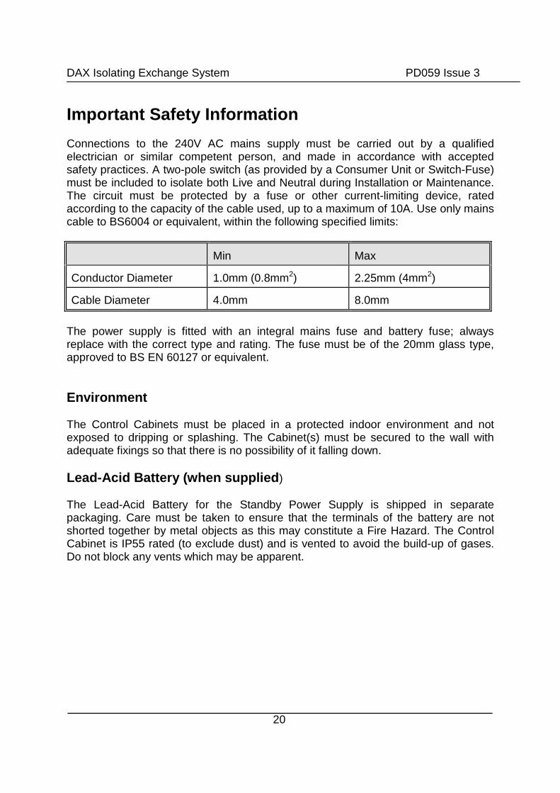
Connections to the 240V AC mains supply must be carried out by a qualifiedelectrician or similar competent person, and made in accordance with acceptedsafety practices. A two-pole switch (as provided by a Consumer Unit or Switch-Fuse)must be included to isolate both Live and Neutral during Installation or Maintenance.The circuit must be protected by a fuse or other current-limiting device, ratedaccording to the capacity of the cable used, up to a maximum of 10A. Use only mainscable to BS6004 or equivalent, within the following specified limits:
Min Max
Conductor Diameter 1.0mm (0.8mm2) 2.25mm (4mm2)
Cable Diameter 4.0mm 8.0mm
The power supply is fitted with an integral mains fuse and battery fuse; alwaysreplace with the correct type and rating. The fuse must be of the 20mm glass type,approved to BS EN 60127 or equivalent.
Environment
The Control Cabinets must be placed in a protected indoor environment and notexposed to dripping or splashing. The Cabinet(s) must be secured to the wall withadequate fixings so that there is no possibility of it falling down.
Lead-Acid Battery (when supplied)
The Lead-Acid Battery for the Standby Power Supply is shipped in separatepackaging. Care must be taken to ensure that the terminals of the battery are notshorted together by metal objects as this may constitute a Fire Hazard. The ControlCabinet is IP55 rated (to exclude dust) and is vented to avoid the build-up of gases.Do not block any vents which may be apparent.

DAX Isolating Exchange System PD059 Issue 3
21
InstallationInstalling the cables
Before Installing any cables study the wiring diagrams, and read thoroughly thesections on >cable planning’, and the notes on equipment installation describedbelow. The entire system of cables may then be installed in the building ready forfitting of the equipment.
Fitting the Control cabinets
The control cabinets are designed to be wall-mounted in a protected indoorenvironment such as an Electrical Cupboard. Position them within the building insuch a way as to minimise the length of cable runs to the telephones and EntrancePanels. Ensure that there is a 240VAC mains supply available (via a Switch-Fuse orConsumer unit) and that there is easy access for maintenance.
Four holes are provided at the back of the cabinet for mounting to a vertical wall;ensure that the correct fixings are used for the type and construction of the wall; testthe strength of the fixings before connecting the mains supply. Cable access isprovided at the top with a removable plate. For drilling of cable clearance holes orconduit fittings, remove this plate from the equipment, to avoid metal particles fromfalling onto equipment.
Connect all signal cables according to diagram 4 in the appendix, observing thetwisted pairs as described in the section >Cable-Planning’. The cable for eachtelephone must be connected to the correct output of the RLX8 relay boards in theControl Cabinet, to enable it to operate from the required flat number. The RLX8connections are labelled 1 to 56. The corresponding flat number is given on the 'DAXDoor Entry System Configuration Summary' supplied. If Partial Isolation telephonewiring is used with BS-LX series telephones (refer to page 11) each RLX8 PCBmust have fuse FS1 replaced with a F1.5A Quickblow type.
A 240VAC mains connection is required to the Power Supply. It is advisable to use aplastic conduit to protect the mains cable within the cabinet. To make theconnections, remove the PSU lid by removing the fixing screws. Feed the cablethrough the grommet and cable-clamp and connect the Live, Neutral and EarthConnections as marked. Refit the PSU lid. Do not connect the battery at this stage.

DAX Isolating Exchange System PD059 Issue 3
22
Fitting the Entrance Panels
Choose a position on the wall of the building as close as possible to the entrance,which allows easy access for cables. If possible, avoid an open, south-facing aspectfor optimum visibility of the display throughout the day (i.e. avoiding direct sunlight).As a guide, the height to the display window maybe approx. 1.4m above groundlevel. This height may need adjusting for disabled callers.
Cut a hole in the wall slightly larger than the back-box but a clear margin smaller thanthe panel; ensure there is a sufficient clearance for the cables if they are to exit fromthe top or bottom.
Extract the main panel from the back-box by removing the two vandal resistant bolts(a special key is provided) and place it where it is protected from damage. Secure theback-box to the wall with four heavy-duty fixing screws. Seal the back-boxflange/bezel to the wall with a non-corrosive silicon sealant, making sure not to sealthe bottom edge (to avoid moisture build-up). Feed in the necessary cables throughholes in the back, top or bottom of the back-box and make all connections inaccordance with wiring diagram 4 in the appendix.
Before refitting the Entrance Panel ensure the Model 61 Speech Unit is correctlypositioned and check (and adjust if necessary) the two volume controls are approx.mid-way. Finally refit the Panel and remove the protective film from the displaywindow.
Fitting the Telephones
All the Models of Door Entry Telephone described above, are designed to be Wall-Mounted. Position them approx. 1.2m from floor level (adjust the height for anydisability requirement). Make a cavity in the wall and feed through the required cable.Remove the lid of the telephone by pulling it straight off. The cable should be fedthrough the access hole in the base of the telephone and the telephone secured tothe wall with two fixing screws. Strip the cable to length and connect according todiagram 5 or 6 in the appendix. Refit the lid and then hang-up the handset ready fortesting.

DAX Isolating Exchange System PD059 Issue 3
23
Testing and Commissioning
Turning the system on for the first time
Switch on each control Cabinet in turn, performing basic checks before moving on tothe next:
With the battery still disconnected, switch on the mains supply and then turn on thePower Supply. The Power Supply ON/OFF switch should illuminate to indicate ahealth mains supply and a steady green Lamp will confirm correct operation of thePSU. As soon as power is applied, a Red LED will flash four times on the CTX64PControl Board (or EXP64 if present), again confirming correct operation. In the eventof any difficulties refer to the section on troubleshooting.
Testing the Entrance Panel
Visit each Entrance Panel in turn and confirm operation of the LED display byentering any flat number and then pressing cancel (refer to Operation page 3). Ifthere is nothing displayed or there are unexpected messages, refer to the section onTroubleshooting.
System Programming
A number of system settings (e.g. lock duration, access code) may be customisedduring Installation; refer to the section on >Programming the Entrance Panel’. It isadvisable to program all Entrances to the required operation, at this stage, to avoidrepeating the following tests.
Testing the Telephones
Refer to the Operating Instructions page 3; Two Engineers are required to performthese tests. Alternatively, use Test Mode: Page 36.
Work systematically through the flat numbers from the Printouts provided followingthe sequence of Relay numbers (1 to 56 on the RLX8 PCBs).
Call the first telephone checking that the telephone buzzer is audible and that two-way speech is possible and of good quality. Press the telephone lock button andcheck the lock release operates.

DAX Isolating Exchange System PD059 Issue 3
24
If the telephone is a BS-LX model, press the mute switch and check the red LEDturns on and off. If a door monitor contact/switch is present, open the door and checkthe green light comes on or flashes.
Testing the Time-clock
Program the required time-periods for Trades operation by referring to the bookletincluded with The TS2000-BST Time-Clock Module.
Testing the system on battery standby(Read the section on >Important Safety Information=)
When all system tests are completed, the Lead-Acid battery (if required) may beinstalled in each Control cabinet. The battery is placed on the bottom of the Cabinetand connected by two leads with spade terminals to the CAB5 Power Supply.Observe the correct polarity (red to positive; black to negative). The PSU shouldremain operating with a steady green lamp.
Now simulate a Mains failure by switching the PSU off (the switch should cease toilluminate). Battery operation should be confirmed with a flashing green lamp on thePSU. Confirm that the system continues to operate normally, by re-testing the systemfrom one telephone. Re-instate the Mains.
Other Tests
The following additional tests should be performed to verify correct operation andprogramming of each facility if used on the system:
Door Monitor: Check that the Door Open Indicator on the telephonesoperates from the required doors.
Egress Button: Check that pressing this button operates the Lock releasefor the prescribed period of time.
Trades/Coded Access: Check that these features operate exactly asprogrammed; if required the time clocks can be switchedon or off manually to simulate the active time-periods.
DAX Isolating Exchange System PD059 Issue 3
25
Display
If the display window in the module itself, or at the entrance panel, requires cleaninguse a mild detergent and NOT an abrasive cleaner.
Speech Adjustment
The Model 61 Speech Unit has two pots at the rear for adjustment of Speech levelsas follows:
Volume A: Speech level heard at the Entrance PanelVolume B: Speech level heard at the Telephone
If feedback is experienced (a howl or a whistle) turn both controls to >off= and slowlyadjust each up in turn until a satisfactory level of speech is attained.

DAX Isolating Exchange System PD059 Issue 3
Programming The Entrance Panels
Entering Program Mode
Set the PROG/RUN switch on any Door Controller or System Expander PCBto PROG; The Displays shows
Enter the security code: 1010 (this protects against inadvertent use by aCaller).
All other entrances will show
After 3 minutes of no activity thi
Selecting a Parameter
On entering Program Mode,between the parameter number
To step through to the requPressing the >TRADES= button a
Changing a parameter
If the Parameter has a numericand press the CALL button. If areturn to the previous valuebutton. If a value is out of thunchanged.
If the Parameter has an optisettings with the CALL button.
PGM
P1 123
26
s entrance will return to the same prompt.
the first parameter is displayed. Alternatingand the current value / setting.
ired parameter press the >TRADES= button.fter the last parameter will return to the first.
value, type the new value using the keys 0-9n incorrect value is entered press CANCEL to
and then re-enter before pressing the CALLe allowable range the parameter will remain
on list or yes/no setting, toggle through the
PGM
4

DAX Isolating Exchange System PD059 Issue 3
27
Programmable parameters
Parameter 1 - Trades code
Display:
Range: Any 4 digit code.
Default: 1234
Description: The code to enter a premise when the trade’s button is pressed.To enable this code, parameter 5 and / or 6 need setting toACODE@.
Parameter 2 - Lock release time
Display:
Range: 1- 20 seconds
Default: 5 seconds
Description: The time a lock release operates or continues to operate after atelephone lock button has been pressed, trades/coded accesswas used or the egress / fireman’s switch was operated.
Parameter 3 - Speech time
Display:
Range: 20 - 240 seconds
Default: 60 seconds
Description: The time for which two-way conversation is possible betweenResident and Caller before the system automatically disconnectsthe line. During Test Mode this time is extended to 10 minutes.
P1 1234
P2 3
P3 60

DAX Isolating Exchange System PD059 Issue 3
28
Parameter 4 - Phone Buzz time
Display:
Range: 0 - 10 seconds
Default: 0 seconds
Description: The time a telephone buzzer sounds after the caller has releasedthe CALL or PORTER buttons to make a call.
Parameter 5 - Timer on access
Display:
Range: NO, IMM, CODE
NO No accessIMM Immediate access, no code required.CODE Code required.
Default: NO
Description: Action required when the TRADES button is pressed whilst theTime-Clock module is ON.
Parameter 6 - Timer off access
Display:
Range: NO, IMM, CODE
NO No accessIMM Immediate access, no code required.CODE Code required.
Default: NO
Description: Action required when the TRADES button is pressed whilst theTime-Clock module is OFF.
Parameter 7- This is reserved
P4 0
P5 NO
P6 NO
DAX Isolating Exchange System PD059 Issue 3
29
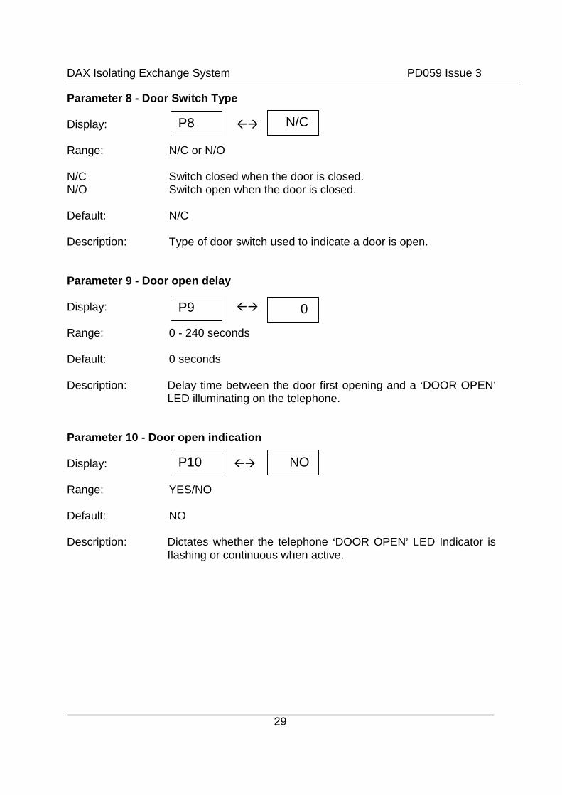
Parameter 8 - Door Switch Type
Display:
Range: N/C or N/O
N/C Switch closed when the door is closed.N/O Switch open when the door is closed.
Default: N/C
Description: Type of door switch used to indicate a door is open.
Parameter 9 - Door open delay
Display:
Range: 0 - 240 seconds
Default: 0 seconds
Description: Delay time between the door first opening and a >DOOR OPEN=LED illuminating on the telephone.
Parameter 10 - Door open indication
Display:
Range: YES/NO
Default: NO
Description: Dictates whether the telephone >DOOR OPEN= LED Indicator isflashing or continuous when active.
P8 N/C
P9 0
P10 NO

DAX Isolating Exchange System PD059 Issue 3
30
Parameter 11 - Door number
Note: This parameter is factory set and should not need adjusting.Incorrect setting may result in temporary loss of systemoperation, or partial operation.
Display:
Range: 1 - 32
Default: System dependant
Description: Address of the Door Controller currently being Programmed.
One controller in the system must have an address of 1. Theaddress of each must be unique and cannot be the same as aSystem Expander phone bank address.
Parameter 12 - Maximum address
Note: This parameter is factory set and should not need adjusting.Incorrect setting may result in temporary loss of systemoperation, or partial operation.
Display:
Range: 1 - 32
Default: System dependant
Description: The highest address used by any Door Controller or SystemExpander in a system. This must be set to the same value forevery entrance.
P11
P12 2
1

DAX Isolating Exchange System PD059 Issue 3
31
Parameter 13 - Timer door number
Note: This parameter is factory set and should not need adjusting.
Display:
Range: 1 - 32
Default: 1
Description: The address of the Door Controller, which has the required timeclock directly connected.
Parameter 14 - System Expander Address
Note: This parameter is factory set and should not need adjusting.
Display:
Range: 2 - 32
Default: System dependant
Description: The address of the System Expander (EXP64 PCB), or phonebank, directly connected (in the same cabinet) to this entrances’Door Controller (CTX64P PCB). If no System Expander ispresent, this variable can be ignored.
P14
P13
3
1

DAX Isolating Exchange System PD059 Issue 3
32
The TS2000-BST Time-Clock Module
Please refer to the leaflet supplied with the TS2000-BST Time Clock. The leaflet canbe downloaded at www.bellsystem.co.uk.

DAX Isolating Exchange System PD059 Issue 3
Test Mode
Test mode is provided to enable an unaided Installer to make more rapid tests of thesystem when compared to the normal operating mode. It enables each telephone tobe connected for an extended period whilst checks are made at the Entrance Panel,the Telephone and the Control cabinet. Speech connections can be rapidly steppedthrough for each Telephone (1 to 56) in each cabinet (1-4), from either a singleEntrance Panel, or Door Controller PCB.
To enter Test Mode:
Ensure all RUN/PROG switches are set to RUN.
Press the test button marked SW3 on the Door Controller PCB of the requiredentrance.
Test mode is confirmed by;
1. Door Controller PCB (CTX64P) LED flashing red (see DiagnosticLEDs).
2. LCD Display showing,
flat number on the system
3. Connection made to the
4. Display messages in low
All other entrances will be set to
To exit Test mode:
Switch the RUN/PROG switchflash then return the switch to >R
Test mode is disabled approxim
33
where nnnn is the first
.
first telephone.
ercase.
idle, disconnecting any calls in progress.
to PROG, wait for the LED to start an evenUN=.
ately 10 minutes after the last key press.
nnnn

DAX Isolating Exchange System PD059 Issue 3
34
Using Test Mode from an Entrance Panel
Enter test mode as above.
CALL: Pressing the button will buzz the current telephone and two-wayspeech is possible; The telephone lock button can be used to releasethe door and the telephone is re-connected immediately afterwards.
CANCEL: Pressing this button will display allowing a new flat
number, or starting point, to be entered.
Using Test Mode from a Door Controller PCB
Enter test mode as above.
Operation is essentially the same as from the Entrance Panel:
INC: Press SW3 to step to the next flat.
CALL: Press SW2 to buzz the phone.
Note: These buttons may be used alternately with the controls on the Entrance Panelas described above.
>

DAX Isolating Exchange System PD059 Issue 3
35
Diagnostic LEDs
A diagnostic LED is provided on each Door Controller PCB and System ExpanderPCB to indicate its current operating mode. Two diagnostic LEDs are present oneach Power Supply.
Control PCB (CTX64P)
LED state Operating Mode
Off Operating Mode- Entrance is inactive
On continuously Operating Mode - Entrance is connected to atelephone
1 second ON; 1 second OFF Program Mode - Awaiting security code
Rapid Flashing Program Mode - Data Entry
2 second ON; 1/2 secs OFF Test mode- Entrance is connected to atelephone
2 Seconds OFF; 1/2 secs ON Test mode - no entrance / telephone connected.
Expander PCB (EXP64)
LED state Operating Mode
OFF Operating Mode - No telephone connectedwithin Control cabinet
ON Operating Mode-Telephone connected withinControl Cabinet.
Flashing (1sec ON; 1sec OFF) Program Mode
Power Supply (CAB5 or CAB3)
Steady Green Lamp System running from the mains.
Flashing Green Lamp System running from the battery.
Steady Red Lamp Output off; Battery Charging.
Flashing Red Lamp Output short circuit or battery low.

DAX Isolating Exchange System PD059 Issue 3
36
Troubleshooting
PROBLEM PROBABLE CAUSE AND REMEDY
No / Low speechvolume
>Vol A= or >Vol B= adjustment required on theSpeech unit.
Speech unit supply voltage low. Check 10-15Vacross >C= and >H= on the unit.
Cable fault on R&O, T&O connections ofTelephone or Speech unit, or R, T, 0Vconnections between cabinets.
Constant tone /feedback when in use.
>Vol A= or >Vol B= adjustment required on theSpeech unit.
Speech unit is not tight against the panel grill orpanel grill is blocked.
Missing >O= connection on the telephone.
Telephone will notbuzz.
With an 801S or BS-LX phone check the buzzerhas not been muted (telephone red LED on withBS-LX).
Faulty O or I connection to telephone. Faulty V (12V) or O (0V) connection (BS-LX only). Telephone wired to incorrect Relay PCB (RLX8)
connection. Check the >DAX Door Entry SystemConfiguration Summary= supplied.
Check the >+S= and >-S= connections betweencabinets.
Door open indicatorwill not light.(BS-LX only)
Door open local/any feature dipswitch setincorrectly; refer to table 4 in the Appendix.
Parameter 9, door open delay, set too long. Faulty L or V connection to telephone.
Faulty connection to a door switch. Try shortingDOOR SW connections at the CTX64P PCB.
Phone lock buttondoes not operate lockrelease.
Faulty connection on Z or O line. Try shorting Z toO at the RLX8 PCB, when telephone active.
Voltage drop due to inadequate cable to Lock.
Lock release operatesall the time.
If the lock is a >fail safe= type it has beenconnected to a >FAIL SECR= output. If the lock is a>fail secure= type it has been connected to a >FAILSAFE= output. Try swapping the connections over.

DAX Isolating Exchange System PD059 Issue 3
EXIT inputs permanently shorted together.
Display blank at alltimes.
No/low Display module supply. Check 10V-15Vacross +V and 0V on the module.
Display shows Faulty D connection to Display module.
Pressing TRADESdisplays
when not expected
Check the Time Clock module is correctlyprogrammed and switched on.
Check parameters 5, 6,13 are programmedcorrectly
Check >+S= and >-S= connection between cabinets.
Pressing a Panel Keyhas no, or the wrong,effect.
Faulty or incorrectly wired Keypad. Check all 8connections between Panel and Door Controllerare correct, use diagram 4 and 8 to aid.
Unable to use normaloperation; displayshows
A RUN/PROG switch is set to PROG; check allCTX64P and EXP64 PCBs on the system.
Supply(less thasystem co
DENY
F1
vn
37
Short circuit between PG and 0V connections
oltage low10V, any
mponent).
Short circuit. Check all control cabinets for a redflashing LED on a power supply.
Systematically disconnect cables (excepttelephones) one at a time from the cabinets untilthe fault clears. Reset the power supply each timeby switching OFF and ON. Check Battery fuseafter fault has been cleared
PGM

DAX Isolating Exchange System PD059 Issue 3
38
Technical Specification
Max. telephones 256 as standard (depends on no. of RLX8 PCBs fitted)Max. entrances 4 as standard (depends on no. of CTX64P PCBs fitted)
Mains supply 230V AC +10% 50Hz
Power Consumption 120W Maximum per Control cabinet.
Operating Temperature Entrance Panel: -11C to + 40CControl Cabinet: 0 C to + 40C
Battery Fuse F6.3A (Fast blow).
Battery (optional). 12V 7AH Lead-Acid, Maintenance free.

DAX Isolating Exchange System PD059 Issue 3
39
Appendix

DAX Isolating Exchange System PD059 Issue 3
40
Table 4 System Expander DIP switch
Table 4a Door open local/any feature
Door OpenCondition
DIP Switch setting
1 2 3 4 5 6 7 8
Local X X X X X X X 1
Any X X X X X X X 0
0- Up 1 - DownX - No affect on feature
Table 4b Phone bank address
This is factory set and should not need altering. The address has to be uniqueand not the same as a door address (see parameter 11).
BankAddress
DIP Switch setting
1 2 3 4 5 6 7 8
2 0 1 0 0 0 0 X X
3 1 1 0 0 0 0 X X
4 0 0 1 0 0 0 X X
5 1 0 1 0 0 0 X X
6 0 1 1 0 0 0 X X
7 1 1 1 0 0 0 X X
8 0 0 0 1 0 0 X X
0 - Up 1 - DownX - Independent of setting

Dia
gra
m4
En
tran
ce
Co
nn
ec
tio
ns

Dia
gra
m5
Tele
ph
on
eC
on
necti
on
sfo
rF
ull
Iso
lati
on
Wir
ing

Dia
gra
m6
aT
ele
ph
on
eC
on
necti
on
sfo
rP
art
ial
Iso
lati
on
Wir
ing
(RL
X8)

Dia
gra
m6b
Tele
ph
on
eC
on
necti
on
sfo
rP
art
ial
Iso
lati
on
Wir
ing
(RL
XC
)

Dia
gra
m7
Co
nn
ecti
on
sb
etw
een
DA
XC
on
tro
lC
ab
inets

Dia
gra
m8
Hig
hC
urr
en
tL
ock
Rele
ase
s

DPX Isolating Exchange System PD-059 Issue 3
47
Diagram 9 Keypad Matrix Connections

Bell System (Telephones) Ltd.Presley Way,Crown Hill,Milton KeynesMK8 0ET.
Tel: 01908 261106 (Sales and Technical Support)FAX: 01908 261116
OR
Local rate numbers
Tel: 0845 121 4008 (Sales and Technical Support)FAX: 0845 121 4009
E-mail: [email protected]@bellsystem.co.uk
Website: www.bellsystem.co.uk
Standards
This product complies with European directive 89/336/EEC onElectromagnetic Compatibility and Low Voltage Directive 72/23/EEC.Emissions: Generic BSEN 50081-1Immunity: Generic BSEN 50082-1Low Voltage: Generic BSEN 60950
BS EN ISO 9001:2000 Certificate number GB2000389


