This is an electronic reprint of the original article. This reprint may differ from the original in pagination and typographic detail. Powered by TCPDF (www.tcpdf.org) This material is protected by copyright and other intellectual property rights, and duplication or sale of all or part of any of the repository collections is not permitted, except that material may be duplicated by you for your research use or educational purposes in electronic or print form. You must obtain permission for any other use. Electronic or print copies may not be offered, whether for sale or otherwise to anyone who is not an authorised user. Belloch, Jose A.; Gonzalez, Alberto; Quintana-Ortí, Enrique S.; Ferrer, Miguel; Välimäki, Vesa GPU-Based Dynamic Wave Field Synthesis Using Fractional Delay Filters and Room Compensation Published in: IEEE/ACM Transactions on Audio, Speech, and Language Processing DOI: 10.1109/TASLP.2016.2631338 Published: 01/02/2017 Document Version Peer reviewed version Please cite the original version: Belloch, J. A., Gonzalez, A., Quintana-Ortí, E. S., Ferrer, M., & Välimäki, V. (2017). GPU-Based Dynamic Wave Field Synthesis Using Fractional Delay Filters and Room Compensation. IEEE/ACM Transactions on Audio, Speech, and Language Processing, 25(2), 435-447. [7750558]. https://doi.org/10.1109/TASLP.2016.2631338
Transcript
This is an electronic reprint of the original article.This reprint may differ from the original in pagination and typographic detail.
Powered by TCPDF (www.tcpdf.org)
This material is protected by copyright and other intellectual property rights, and duplication or sale of all or part of any of the repository collections is not permitted, except that material may be duplicated by you for your research use or educational purposes in electronic or print form. You must obtain permission for any other use. Electronic or print copies may not be offered, whether for sale or otherwise to anyone who is not an authorised user.
Belloch, Jose A.; Gonzalez, Alberto; Quintana-Ortí, Enrique S.; Ferrer, Miguel; Välimäki, Vesa
GPU-Based Dynamic Wave Field Synthesis Using Fractional Delay Filters and RoomCompensation
Published in:IEEE/ACM Transactions on Audio, Speech, and Language Processing
DOI:10.1109/TASLP.2016.2631338
Published: 01/02/2017
Document VersionPeer reviewed version
Please cite the original version:Belloch, J. A., Gonzalez, A., Quintana-Ortí, E. S., Ferrer, M., & Välimäki, V. (2017). GPU-Based Dynamic WaveField Synthesis Using Fractional Delay Filters and Room Compensation. IEEE/ACM Transactions on Audio,Speech, and Language Processing, 25(2), 435-447. [7750558]. https://doi.org/10.1109/TASLP.2016.2631338
IEEE/ACM TRANSACTIONS ON AUDIO, SPEECH AND LANGUAGE PROCESSING, VOL. X, NO. Y, NOV. 2016 1
GPU-based Dynamic Wave Field Synthesis usingFractional Delay Filters and
Room CompensationJose A. Belloch?, Member, IEEE, Alberto Gonzalez, Senior Member, IEEE, Enrique S. Quintana-Ortı,
Miguel Ferrer, Member, IEEE, and Vesa Valimaki, Fellow, IEEE
Abstract—Wave Field Synthesis (WFS) is a multichannel audioreproduction method, of a considerable computational cost thatrenders an accurate spatial sound field using a large numberof loudspeakers to emulate virtual sound sources. The movingof sound source locations can be improved by using fractionaldelay filters, and room reflections can be compensated by usingan inverse filter bank that corrects the room effects at selectedpoints within the listening area. However, both the fractionaldelay filters and the room compensation filters further increasethe computational requirements of the WFS system. This paperanalyzes the performance of a WFS system composed of 96loudspeakers which integrates both strategies. In order to dealwith the large computational complexity, we explore the useof a graphics processing unit (GPU) as a massive signal co-processor to increase the capabilities of the WFS system. Theperformance of the method as well as the benefits of the GPUacceleration are demonstrated by considering different sizes ofroom compensation filters and fractional delay filters of order 9.The results show that a 96-speaker WFS system that is efficientlyimplemented on a state-of-art GPU can synthesize the movementsof 94 sound sources in real time and, at the same time, canmanage 9,216 room compensation filters having more than 4,000coefficients each.
Index Terms—Audio systems, interpolation, parallel architec-tures, parallel processing, signal synthesis
I. INTRODUCTION
In the last few decades, there has been increasing interestin enhancing and improving listening experience, especiallyspatial audio rendering [1]. One of the spatial audio tech-nologies available today is Wave Field Synthesis (WFS) inwhich a sound field is synthesized in a wide area by means ofloudspeaker arrays, which are referred to as secondary sources[1]. WFS is usually tackled via digital signal processingtechniques to reproduce complex auditory scenes consistingof multiple acoustic objects, which are generally denoted as
Jose A. Belloch and Enrique S. Quintana-Ortı are with the Depto. deIngenierıa y Ciencia de Computadores, Universitat Jaume I, 12071, Castellon,Spain.? Corresponding author. E-mail: [email protected].
A. Gonzalez and M. Ferrer are with the Institute of Telecomunicationsand Multimedia Applications, Universitat Politecnica de Valencia, 46022,Valencia, Spain.
V. Valimaki is with the Dept. of Signal Processing and Acoustics, AaltoUniversity, Espoo, Finland.
Dr. Jose A. Belloch is supported by the postdoctoral fellowship fromGeneralitat Valenciana APOSTD/2016/069. This work has been partiallysupported by EU together with Spanish Government through TEC2015-67387-C4-1-R and TIN2014-53495-R (MINECO/FEDER), and GeneralitatValenciana through PROMETEOII/2014/003.
primary or virtual sources. The WFS concept was introducedat the Delft University of Technology in the 1980s. Berkhoutdeveloped the first investigations in this field [2], [3], whichwere followed by several dissertation works [4], [5], [6], [7],[8].
One of the practical problems of implementing WFS isthe interaction of the speaker array with the listening room.The room introduces echoes that are not part of the signal tobe reproduced, thus altering the synthesized sound field anddisturbing the spatial effect. One solution that can be added tothe WFS system to minimize the undesirable interaction of thearray with the listening room is a Room Compensation (RC)block. A common RC block is based on a multichannel inversefilter bank and corrects the room effects at selected pointswithin the listening area [9], [10]. This formula was validatedin [11], where significant improvements were presented in theacoustic field when an RC block is applied to a WFS system.In practice, the application of this spatial audio system (WFS+ RC) in real environments (theaters, cinemas, etc.) requiresa real-time solution with high computational requirements.
Another special situation in WFS occurs when it is neces-sary to render a moving sound source through a specific trajec-tory. In a WFS system that is implemented using discrete-timeprocessing, accurate modeling of propagation times requires asignal to be delayed by a number of samples that is not an inte-ger multiple of the sampling intervals. To this end, we proposethe use of fractional delay filters [12], [13] to render the audiosignals in this scenario. These filters are used to interpolate asignal value between the sampling points. Other applicationsof fractional delay filtering in audio signal processing includedigital audio effects [14], [15] and physical sound synthesis[16], [17]. Franck et al. have studied techniques to interpolatetime delays in WFS and have analyzed artifacts that arise whenfractional delays are not considered [18], [19], [20]. The useof fractional delays in a WFS system has also been analyzedin [21], [22], [23].
A large-scale WFS system with massive additional filteringrequires costly computational operations in real time. Onesolution to this problem is to perform all audio processingtasks in a Graphics Processing Unit (GPU). Accelerators ofthis type have already been applied to different problems inacoustics and audio processing. Some applications includeroom acoustics modeling [24], [25], [26], [27], additive synthe-sis [28], [29], full 3-D model of drums in a large virtual room[30], sliding phase vocoder [31], beamforming [32], audio
2 IEEE/ACM TRANSACTIONS ON AUDIO, SPEECH AND LANGUAGE PROCESSING, VOL. X, NO. Y, NOV. 2016
rendering [33], [34], [35], multichannel IIR filtering of audiosignals [36], dynamic range reduction using multiple allpassfilters [37], and adaptive filtering [38], [39], [40].
In recent years, there have been several studies aimed atimplementing a WFS system. An approach that benefited fromtime-invariant preprocessing in order to reduce the computa-tional load is presented in [41]. In [42], the authors propose aminimal processor architecture that is adapted to WFS-basedaudio applications. They estimated that their system couldrender (in real time) up to 32 acoustic sources when driving 64loudspeakers. In [43], the same researchers presented a WFSimplementation on different multi-core platforms, includinga GPU-based implementation that controlled more than 64sources when driving 96 loudspeakers. They concluded thatGPUs are suitable for building immersive-audio, real-time sys-tems. In [44], the authors also introduced a GPU-based hybridtime-frequency implementation of WFS. Real-time issues inWFS were tackled in [45] using the NU-Tech framework [46].
In comparison with previous efforts, the WFS implemen-tation proposed in this work improves the quality of thevirtual sound by adding room compensation and time-varyingfractional delays filters. Moreover, we design our applicationto achieve high performance on GPUs by exploiting a KeplerGK110 [47] co-processor. This architecture can be foundon the Tegra K1 (TK1) systems-on-chip (SoC), which isembedded in the Jetson development kit (DevKit) [48]. It isalso integrated into current mobile devices such as the GoogleNexus 9 tablet [49]. Therefore, this implementation can beported to perform efficiently on GPUs which are currentlyembedded in mobile devices.
This paper extends our previous work [50] in various ways.First, we use fractional delay filters in order to reproduce asound source position with high accuracy and to be able tomove a sound source smoothly using time-delay steps of lessthan one sample along the way. Second, we now implement theWFS system with different sample buffer sizes, which estab-lish the minimum and the maximum time that a sound sourcecan stay in one position and thus the different possibilitiesregarding the speed of the sound source. Finally, for shorterbuffer sizes, we now implement a uniformly-partitioned, FFT-based convolution, which can efficiently convolve FIR filtersthat have a large number of coefficients with audio bufferswith smaller size. The algorithm that we implement wasintroduced in [51] and uniformly splits the room compensationfilters into blocks of the same size as the audio buffer. Thisimprovement is crucial since it reduces the latency of thesystem independently of the size of the room compensationfilters.
This paper presents the performance of a GPU-based dy-namic WFS implementation that (i) allows accurate synthesisof virtual sound source positions and thus accurate movementtrajectories using Fractional Delay Filters; (ii) leverages aninverse filter bank to improve the spatial effect of the WFS; and(iii) is capable of synthesizing a large number of virtual soundsources in real time. We also analyze the potential of usingtime-varying fractional delay filters in WFS and the influenceon the computational time for different sizes of audio buffersand room compensation filters.
This paper is structured as follows. Section II brieflydescribes the key architecture aspects of the target GPUsfrom NVIDIA and highlights the features to be accountedfor when implementing a real-time WFS on this type ofaccelerator. Section III offers a brief overview of the WFStheory. Section IV enumerates different kinds of fractionaldelay filters, assesses which fractional delay filter is the mostappropriate for a WFS system, and tests subjectively thedifferent techniques for carrying out sound source movementsinside this system. Section V presents a detailed description ofa GPU-based implementation of the WFS system. In SectionVI, we evaluate the computational performance of the WFSsystem, and we summarize our results in Section VII.
II. USE OF A GPU IN A REAL-TIME WFS SYSTEM
Dealing with real-time audio applications on GPUs requiresa basic understanding of how architectures of this type areprogrammed. This section provides a brief description of theGPU data flow and outlines some relevant issues to take intoaccount when developing a real-time WFS application on agraphics accelerator from NVIDIA.
A. GPU and CUDA
Following Flynn’s taxonomy [52], from a conceptual pointof view, a GPU can be viewed as a Single InstructionMultiple Data machine (SIMD), i.e., a computer in which asingle flow of instructions is executed on different data sets.Implementations of this model usually work synchronouslywith a common clock signal. An instruction unit sends thesame instruction to the processing elements, which executethis instruction on their own data simultaneously. A GPU iscomposed by multiple Stream Multiprocessors (SM) with 192pipelined cores per SM, for NVIDIA’s 3.5 capability (Keplerarchitecture [47]).
A GPU device has a large amount of off-chip devicememory (global-memory) and a fast, but smaller, on-chipmemory (shared-memory, registers). The shared-memory isnormally used by threads that must share data. There arealso read-only cached memories, which are called constant-memory and texture-memory. Constant-memory is optimizedfor broadcast (e.g., all threads have to read the same memorylocation), while the texture-memory is oriented to graphicsoperations. Fig. 1 shows the organization of a GPU. AdvancedGPU devices (beyond 2.x capability) come with an L1/L2cache hierarchy that is used to cache global-memory. The L1cache uses the same on-chip memory as shared-memory.
An important aspect when reading from or writing to global-memory is to perform these accesses in a coalesced manner,as this can significantly reduce the memory-access time.Coalescing means that the threads have to read from/write to asmall range of memory addresses that match a certain pattern.Let idx be the identification of a thread and array a pointerto global-memory. We attain perfect coalescence when theidx thread accesses the array[idx] and idx+1 accessesthe array[idx+1].
CUDA is an extension of the C language to ease thedevelopment of GPU-oriented efficient solvers for complex
BELLOCH et al.: GPU-BASED DYNAMIC WAVE FIELD SYNTHESIS 3
SP
SMGPU
Shared M. / L1 CacheRegisters
SM
Shared M. / L1 CacheRegisters
SM
Shared M. / L1 CacheRegisters
Constant Memory/Texture Memory
L2 Cache
Global Memory
SP SP SP SPSP SP SP SP
SP SP SP
SP SP SP SPSP SP SP SP
SP SP SP SP
SP SP SP SPSP SP SPSP
SP SP SP SP
Fig. 1. The GPU is configured by 16 Stream Multiprocessors (SMs), eachof which has 192 pipelined cores (SP).
problems with high computational cost [53]. This interfacecan be used to leverage the vast number of execution threadsthat are available in a state-of-the-art GPU. In CUDA, theprogrammer defines the kernel function that contains code(operations) to be executed on the GPU. This kernel routineis invoked from the main program, which also has to definea grid configuration stating the number of execution threadsand how they are distributed and grouped.
B. Real-Time Processing of a WFS System on a GPU
The target WFS system is located at the UniversitatPolitecnica de Valencia (UPV) and is operated by the Audioand Communications Signal Processing Group (GTAC) [54].This system is composed of N=96 loudspeakers that arepositioned in an octogonal geometry, with a separation of18 cm between neighboring loudspeakers (see Fig. 2 for agraphical representation of this configuration).
4.3 m
1.45
m
120º
Fig. 2. Configuration of the WFS loudspeaker array available in the laboratoryof the GTAC at UPV.
The loudspeakers are connected to four MOTU 24I/O audiocards that use the ASIO (Audio Stream Input/Output) driver tocommunicate with the CPU. This driver works with blocks ofL samples obtained with a sampling rate fs. Thus, every Lfsseconds, the audio card requires the loudspeakers to reproduceN output-data buffers of size L. This time is denoted astbuff [35] and is independent of the number of loudspeakersand the number of virtual sound sources (M ) in the WFSsystem. In contrast, the processing time tproc depends bothon M and N . Here, tproc includes the time spent on datatransfers between the GPU and the CPU and the time usedfor the computation on the GPU (CUDA kernels). These data
transfers are carried out via the PCI-e X 16 bus, which has anapproximate bandwidth rate of 8 GB/s. Therefore, the WFSsystem works in real time provided tproc < tbuff . When thiscondition no longer holds, the application can still work off-line (i.e., processing the audio samples in order to reproducethem later).
III. FUNDAMENTALS OF WFSWave Field Synthesis is a sound rendering method that is
based on fundamental acoustic principles [2]. It enables thegeneration of sound fields with natural temporal and spatialproperties within a volume or area bounded by secondarysources (arrays of loudspeakers, see Fig. 2). This method offersa large listening area with uniform and high reproductionquality.
The theoretical basis for WFS is given by Huygens’ prin-ciple [3]. According to this principle, the propagation of awave front can be described by adding the contribution of anumber of secondary-point sources distributed along the wavefront, where a synthesis operator is derived for each secondarysource.
This principle can be used to synthesize acoustic wavefronts of any arbitrary shape. For simplicity, the general 3-D solution can be transformed into a 2-D solution, which issufficient to be able to reconstruct the original sound field inthe listening plane [4], [5], [55]. For that purpose, a lineararray of loudspeakers is used to generate the sound field ofvirtual sources.
Following a model-based rendering in which point sourcesand plane waves are used [56], the field rendered by a soundsource m at a point R, within the area surrounded by Nloudspeakers, can be expressed as
P (xR, ω) =
N−1∑n=0
Qn(xm, ω)e
−jωrnRc
rnR, (1)
where c is the speed of the sound, xm is the position of thevirtual sound source m, xR is the position of the point R,and rnR =| xn − xR | is the distance between the n-thloudspeaker and the point R.
The driving signal of the n-th loudspeaker is represented byQn(xm, ω), which is given by
Qn(xm, ω) = S(ω)
√jω
2πcK
1√rmn
cos(θmn)e−jωrmn
c , (2)
where K is a geometry-dependent constant,rmn =| xm − xn | and xn is the position of theloudspeaker n. Fig. 3 shows the geometry of the system,where θmn is the angle between the line that connects xm
and xn and the normal vector n of the loudspeaker n. Thepiano represents the sound source m. The driving signal (2)consists of several elements that have different functionalities.The term S(ω) is the frequency-domain characteristic of thesource signal, while the term
H(ω) =
√jω
2πc(3)
represents a filtering operation that is independent of theposition of the virtual source. In [57], (3) is referred to
4 IEEE/ACM TRANSACTIONS ON AUDIO, SPEECH AND LANGUAGE PROCESSING, VOL. X, NO. Y, NOV. 2016
Loudspeaker 0
x
Sound Source
Loudspeaker N-1... ... ... ... ... ... ...Loudspeaker n
m
xn
xR
rθ
θ
mn
rnR
mn
mn
Fig. 3. Geometry of a WFS system with the sound source m (piano), Nloudspeakers, and the distances among the sound source, the loudspeakers,and the listener (R).
as a WFS pre-equalization filter that represents a lowpassfilter with a constant slope of 3 dB/octave when the loud-speaker is considered a monopole secondary source. If theloudspeaker is considered a dipole secondary source, the WFSpre-equalization filter corresponds to a highpass filter with amagnitude increase of 3 dB/octave. An important contributionin (2) is
amn =K√rmn
cos(θmn), (4)
which denotes an amplitude factor that depends on the posi-tions of the sound source m and the loudspeaker n. Finally,the term e
−jωrmnc represents the phase shift corresponding to
a time delay that depends on the distance between the virtualsound source m and the loudspeaker n.
The driving signal shown in (2) can also be expressed inthe time domain as
qmn (t) = amnsm(t) ∗ h(t) ∗ δ(t− | xm − xn |c
), (5)
where ∗ denotes the convolution operator, sm(t) is the signalof sound source m, and h(t) is the inverse Fourier transformof H(ω) in (3).
In a multi-source system composed of M virtual soundsources, the loudspeaker driving signal of the nth loudspeakeris
qn(t) =
M−1∑m=0
qmn (t). (6)
In a discrete-time signal processing system with samplingfrequency fs, (5) and (6) boil down to
qn[k] =
M−1∑m=0
amnsm[k] ∗ h[k] ∗ δ[k − τmn], (7)
where k is the sample index, and
τmn =| xm − xn |
cfs (8)
is the delay in number of samples.
A. Room Compensation in a WFS System
The interaction of the driving signals with the listeningroom can deteriorate the rendering properties of the WFSsystem. The synthesized sound field can be altered by newechoes that are introduced by the listening room, reducing thespatial effect. In [11], [58], the authors designed and validateda multichannel inverse filter bank that corrects these roomeffects at selected points within the listening area. However,in a WFS system composed of N loudspeakers, this impliesinserting N2 FIR filters to the system, considerably increasingits computational demands. The operations that are carried outin a multichannel inverse filter bank with every driving signalare given by
yn(t) =
N−1∑j=0
qj(t) ∗ fjn(t). (9)
Thus, the final signal to be reproduced by the n-th loudspeakeryn(t) is a combination of all of the filtered signals (asillustrated in Fig. 4), where the filter f0n(t) transmits thedriving signal q0(t) to the loudspeaker n.
Driving Signal N-1
Loudspeaker 0
f (N-1)(N-1)fj(N-1)f 0(N-1)
q (N-1)
Driving Signal jq j
Driving Signal 0q 0
f (N-1)nfjnf0nf (N-1)0f j0f00
y0 y
n y(N-1)
Loudspeaker n Loudspeaker N-1
Fig. 4. Multichannel inverse filter bank, where each driving signal isconvolved by N filters. The signal that is reproduced by a loudspeaker isa combination of all of the filtered signals.
The calculation of the inverse filters can be carried outin a setup stage since the main room reflections at lowfrequencies, can be considered to be invariant for this specificroom. Different methods have been proposed to obtain thebank of correction filters. There are methods that compute anapproximate solution in the frequency domain using the FFT[59]. In this work, we instead leverage a method to computethe correction filters fjn, which guarantee a minimal squareerror solution in the time domain [60]. A detailed descriptionof the operations that were carried out for the computation ofthe filters is reported in [11].
B. Accurate Location in Dynamic Sound Sources
The virtualization of the sound source movements is carriedout by smoothly varying the virtual positions of sound sourcesover time. In practice, this implies switching the synthesis ofthe sound source from the actual position to a new position.Considering a linear loudspeaker array composed of 24 loud-speakers, such as that in Fig. 5, we can define a uniform gridof points where a virtual sound source and a possible trajectoryof the sound source (dark thin arrow from left to right) canbe set.
BELLOCH et al.: GPU-BASED DYNAMIC WAVE FIELD SYNTHESIS 5
dAB
A B
Fig. 5. Trajectory of the sound source (dark thin arrow from left to right),where dAB is the trajectory resolution of the WFS system (dark double arrowbetween point A and point B).
TABLE ISPEED OF A VIRTUAL SOUND SOURCE IN A WFS SYSTEM FOR DIFFERENTCOMBINATIONS OF BUFFER SIZE L AND RESOLUTION dAB AT fs = 44.1
KHZ.
dAB (in m) Sizes of buffers L (samples)64 256 1024
Depending on the displacement between the grid points ofthe sound source, we can also define dAB as the minimumdistance between two contiguous points (dark double arrowbetween point A and point B in Fig. 5). If the sound sourcemovement is limited to a fixed displacement, dAB will denotethe trajectory resolution of the WFS system. The trajectoryresolution will also constrain the speed that a virtual soundsource can achieve, since this is given by dABfs/L, where fsis the sampling frequency. Several speed examples obtainedfrom the combination of different sizes of input-data buffersand trajectory resolutions dAB are shown in Table I with thesampling frequency of 44.1 kHz.
Table II shows the maximum variation that is observedin the amplitudes amn and the delays τmn of the drivingsignals for different trajectory resolutions dAB when a virtualsound source m is shifted following the trajectory markedin Fig. 5. This means that, if this virtual sound source isinitially synthesized at point A, and later at point B, itsparameters aAmn and τAmn radically change to aBmn and τBmn.The second and third columns of Table II illustrate the differ-ences max | aAmn − aBmn | and max | τAmn − τBmn |, taking intoaccount that all 24 loudspeakers are reproducing this particularsound source displacement.
Table II indicates that the growth of dAB yields largerdifferences in amplitudes and delays during the displacement.This can lead to discontinuities in the synthesized signals (i.e.,to the appearance of non-linear artifacts). At this point, weface two possible scenarios. First, we can use a crossfadetechnique to reduce artifacts as proposed in [61]. This tech-nique synthesizes a sound source in both positions (point Aand point B) and then combines them by means of a gradualincrease in the sound rendered by the new position (fade-in)while the sound rendered by the old position decreases (fade-
TABLE IIMAXIMUM CHANGES IN THE AMPLITUDES AND DELAYS IN THE DRIVINGSIGNALS WHEN A VIRTUAL SOUND SOURCE IS SHIFTED IN STEPS OF dAB
IN METERS.
dAB (in m) max | aAmn − aBmn | max | τAmn − τBmn |0.0001 0.0001 0.01260.0010 0.0014 0.12600.0025 0.0035 0.31490.0035 0.0048 0.44080.0050 0.0070 0.62980.0070 0.0090 0.88150.0075 0.0105 0.94470.0080 0.0112 1.00770.0090 0.0124 1.13340.0100 0.0140 1.25960.0500 0.0721 6.29590.1000 0.1387 12.58640.3000 0.3969 37.6863
out) in the same proportion. Thus, it doubles the number ofoperations to compute. The second option consists in usingsmall dAB values, since the variations in amplitudes areinsignificant as the virtual sound source shifts. However, thedelays vary substantially in comparison with the amplitudes.In fact, the use of a trajectory resolution of less than 8 mmrequires the introduction of an interpolation technique thatallows delay values that are smaller than one sample intervalto be produced. Hence, in order to achieve suitable trajectoryresolutions, and thus to delay a signal by a number of samplesthat is not an integer value, we propose an alternative approachbased on the use of fractional delay filters.
IV. TIME-VARYING FRACTIONAL DELAY FILTERS
Computing the delays τmn implies delaying a signal by anumber of samples that is not always an integer value. Acommon solution to this problem consists in rounding τmn
to the nearest integer. However, this can lead to acousticartifacts [20]. Fractional delay filters allow a digital signal tobe delayed by a fractional number of samples [12]. Differentfractional delay techniques, such as linear interpolation, cubicinterpolation, and Lagrange interpolation have been presentedin [16]. Linear interpolation is achieved by filtering the signalthrough a first-order FIR filter
y[k − α] = (1− α)y[k] + αy[k − 1], (10)
where α is a decimal number so that 0 ≤ α <1.Cubic interpolation is achieved by filtering the signal
6 IEEE/ACM TRANSACTIONS ON AUDIO, SPEECH AND LANGUAGE PROCESSING, VOL. X, NO. Y, NOV. 2016
A more accurate technique for fractional delay FIR filterdesign was introduced in [62]. It is based on truncatinga Lagrange fractional delay filter. This approach deletes anumber of coefficients at the beginning and at the end ofthe coefficient vector of a prototype Lagrange fractional delayfilter. This technique can be interpreted as a hybrid methodthat combines properties of the Lagrange and the truncatedsinc fractional delay filters [16]. The design of the coefficientsis computationally efficient and is based on a polynomial for-mula. In practice, the P -th order truncated Lagrange fractionaldelay filter hfd[k] is obtained by discarding the K1 coefficientsfrom each end of the T -th order prototype Lagrange FractionalDelay filter hL[k] as
hfd[k] =
0 0 ≤ k ≤ K1 − 1hL[k] K1 ≤ k ≤ P +K1
0 P +K1 + 1 ≤ k ≤ T
hL[k] =
T∏p=0,p6=k
D − pk − p
, (13)
where T > P , K1 is a positive integer (K1 > T/2) and D isa real number that depends on the fractional delay [12], [63].
In order to assess the effect of the fractional delays in aWFS system, we provide an objective comparison among threedifferent WFS driving signals. In all cases, our test sounds arecomposed of one specific tone f and have a duration of 3seconds (signals composed of 3fs samples). The worst casescenario corresponds to a frequency f = 15 kHz at fs =44.1 kHz since this frequency stays within the standard audiobandwidth of 20 kHz and causes large variations in the soundwave. Although a WFS system presents an aliasing frequencythat reduces the spatial effect, the human auditory system isnot very sensitive to these aliasing artifacts [56] and all thesignal components are rendered without limitation. Thus, itis reasonable to evaluate the behavior of the WFS system athigh frequencies in order to obtain an error bound. There arethree different WFS driving signals generated from the virtualsound source:QI,n is the reference ideal signal. From amn and τmn (m
is equal to 1), it is computed as
QI,n = amn sin(2πf
fs(k − τmn)); (14)
where k is the sample index k ∈ {0, 1, 2, . . . , 3fs −1}, n ∈ {0, 1, 2, . . . , 23}. The number of loudspeak-ers that are involved in the WFS system is 24,following the setup shown in Fig. 5.
QR,n is obtained by delaying a computed WFS signal byτmn samples, where τmn is obtained by roundingτmn to the nearest integer,
qn = amn sin(2πf
fsk), and (15)
QR,n = qn ∗ δ[k − τmn].
Qfd,n is obtained from the fractional delay filter. To thisend, a WFS signal must first be obtained by delayinga computed WFS signal by τmn = bτmnc. Then,
the obtained signal is filtered through the fractionaldelay filter hfd, whose coefficients depend on thedifference between τmn and τmn.
The signal Qfd,n takes different forms depending on howthe coefficients of the fractional delay filter were obtained:by means of linear interpolation, QfdL,n, cubic interpolation,QfdC ,n, or truncated Lagrange interpolation, QfdT ,n. In thelast case, the fractional delay filters are configured with a 9th-order truncated filter from the 29th-order prototype since thispresents a wider range of fairly flat frequency response thanthe standard Lagrange Interpolation filter (see [62]). Note thatfilter h from (3) is not taken into account in the previousequations since it has the same influence on all signals.
A. Evaluation of Fractional Delay Filters
We perform a sound source movement following the tra-jectory marked in Fig. 5 (grey thin arrow from left to right)so that all 24 loudspeakers are active (reproducing) duringthe entire movement. This array is implemented with the 24loudspeakers that are located in one of the horizontal sidesof Fig. 2. The sound source movement is generated for fivedifferent trajectory resolutions dAB ∈ {0.0001 m, 0.0010 m,0.0025 m, 0.0050 m, 0.0100 m} and the four proposed synthe-sized signals: QR,n, QfdL,n, QfdC ,n, and QfdT ,n.
We compare the four synthesized signals with the referenceQI,n to measure which group of the synthesized signals bestmatches the theoretical WFS signals. Therefore, we computethe Mean Relative Error (MRE):
MREj =
∑24n=1
∑3fsk=1(QI,n[k]−Qj,n[k])
2∑24n=1
∑3fsk=1(QI,n[k])2
, (17)
where the subscript j ∈ {R, fdL, fdC , fdT } represents eachone of the four proposed synthesized signals: QR,n, QfdL,n,QfdC ,n, and QfdT ,n. Table III shows that, as the trajectoryresolution increases, the MRE grows because it is moredifficult to match the ideal signal. The MRE is reduced whenthe synthesis is carried out using fractional delays instead ofrounding the delays to the nearest integer. In fact, the truncatedLagrange interpolation delivers the closest approximation tothe ideal case.
TABLE IIIMRE FOR DIFFERENT TRAJECTORY RESOLUTIONS dAB (IN METERS) FORTHE PROPOSED SYNTHESIZED SIGNALS IN DECIBELS AT fs = 44.1 KHZ.
dAB (in m) Mean Relative Error (in dB)QR,n QfdL,n QfdC ,n QfdT ,n
BELLOCH et al.: GPU-BASED DYNAMIC WAVE FIELD SYNTHESIS 7
B. Subjective Evaluation
We have carried out an informal listening test where wehave compared three different techniques for carrying out asound source movement inside a Wave Field Synthesis system.All of the sound source movements had the same durationand consisted in a piano sound that followed the trajectoryillustrated in Fig. 6.
Fig. 6. Trajectory that followed the sound source for carrying out thesubjective tests. When the piano arrives to one of the ends, it turns backand continues successively till the end of the sound.
The three techniques were generated and labeled as:NO No interpolation. The sound source is moving by
drastically changing spatial positions by small jumpsof dAB = 0.1 m (the virtual sound source is initiallysynthesized at point A, and later at point B. Itsparameters aAmn and τAmn drastically change to aBmn
and τBmn).CR Crossfading. This technique synthesizes a sound
source in both positions (point A and point B), andthen combines them by means of a gradual gainincrease in the sound rendered by the new position(fade-in) while the sound rendered by the old posi-tion decreases (fade-out) in the same proportion. Thistechnique requires high computational resources, asit doubles the number of all operations.
FD Fractional delay filtering (proposed method). Thisoption, which is computationally simpler than CRabove, consists of using a small trajectory resolution(dAB = 0.001 m was used) and changes the spatialposition in smaller steps and more quickly to obtaina duration equal to the previous signals. A trajectoryresolution of less than 8 mm requires an interpola-tion technique producing fractional delay values. Toachieve a suitable trajectory resolution, we use of thetruncated Lagrange interpolation, which delivers aclose approximation to the ideal case (see Sec. V.A).
A subjective test was carried out in order to reveal whichtechnique produces the most realistic movement, taking intoaccount the human perception. We carried out a test in whichthe three techniques were compared using a hidden referenceparadigm [64].
The three techniques were compared by pairs in a test ofsix questions. A total of 21 people participated in the listeningexperiment; their ages were between 23 and 35. The hearingof all test subjects was tested using standard audiometry. None
of them had a reportable hearing loss, which could affect theresults. Fig. 7 shows the preference of the subjects when thethree techniques were pair-compared.
0
5
10
15
20
25
30
35
40
FD NO Ind
39
21
25
1
16
33
2
7
FD vs NO FD vs CR CR vs NO
CR NO IndFD CR Ind
Fig. 7. Preference of the test subjects when the three techniques were paircompared. Ind refers to indifference (i.e., no preference).
The results in Fig. 7 show that the techniques CR andFD are preferred to the NO technique. This symbolizes thatadditional processing must be carried out in order to synthesizea realistic movement. Between CR and FD, the test subjectspreferred FD. This implies that they identify the use of smalltrajectory resolution and a fractional delay interpolation as amore realistic movement than the one which is carried out byusing a crossfading technique. This is a highly useful result,since the implementation based on fractional delay filters,which sounds better, requires also significantly less computingthan the crossfading technique.
V. IMPLEMENTATION OF THE WFS PROCESSING ON THEGPU
As introduced in Section II-B, the WFS system consists ofseveral multichannel audio cards that provide audio buffersevery Lfs seconds, where L is the buffer size in samples. Wedenote the input-data buffer of L samples of the sound sourcem by sbuffm , and the output-data buffer of the L samples thatfeeds the loudspeaker n by ybuffn . We use the GPU to acceler-ate all of the processing tasks of a WFS system that integratesfractional delay filters and room compensation filters. For thispurpose, the operations are applied simultaneously on all ofthe buffers and on each sample.
In previous work [50], we implemented a WFS systembased on an overlap-save technique in the frequency domain.However, in this work we reduce the number of real-time filter-ing computations by convolving filter h (which is independentof the position of the virtual sound source) with all the filtersthat compose the multichannel inverse filter bank followingthe equation
fjn = fjn ∗ h, (18)
where n, j ∈ [0, N − 1]. Thus, our WFS implementation onlyrequires delaying and weighting the source signal:
qn[k] =
M−1∑m=0
amnsm[k] ∗ δ[k − τmn]. (19)
As equation (19) is rather simple, we perform the delay τmn
and the weight amn of the sound signal in the time domainfor this WFS implementation.
8 IEEE/ACM TRANSACTIONS ON AUDIO, SPEECH AND LANGUAGE PROCESSING, VOL. X, NO. Y, NOV. 2016
The WFS system starts from a virtual sound source, whichis defined by its position xm, and the audio samples (which aregiven by audio buffers sbuffm ). The distance rmn and the angleθmn are computed from this position xm and the location ofthe loudspeakers xn (see Fig. 3). Algorithm 1 describes all theoperations that are necessary to execute the WFS system. Theinput variables for this algorithm are the number of soundsources M , the parameters rmn and θmn, the audio bufferssbuffm , and the filters fjn.
The following subsections present a detailed description ofthe GPU implementation of the two key processing blocks:Driving Signals of WFS and Room Compensation filtering.
A. Driving Signals of WFS
We use the following CUDA kernels to compute steps 2 to14 in Algorithm 1.
Kernel 1 launches NM threads and computes steps 5, 6,and 7. The kernel inputs are the coordinates of the virtualsound sources and the positions of the loudspeakers. Eachthread computes a simple factor τmn, τmn, and amn.
Kernel 2 computes the coefficients of the fractional delayfilters (step 8). The highest accuracy is obtained with a 9th-order filter based on truncated Lagrange. In this case, eachfilter is composed of ten coefficients, and, since there is afilter per sound source and loudspeaker, 10NM threads arespawned. Each thread computes a coefficient of one of thefilters.
Kernel 3 computes steps 9 and 10. A tridimensional matrixcomposed of the audio buffers qm
buffnis configured: the num-
ber of rows in this matrix matches the number of sources M ;the number of columns is 2L (number of samples per buffer,see section II-B); and the third dimension corresponds to thenumber of loudspeakers N = 96 in this WFS system (seeFig 8). Therefore, 2LNM threads are spawned. The task ofthe threads is to compute and to group all output audio samplesby considering τmn and amn (combining each sound sourcewith each loudspeaker). The configuration of this matrix iscrucial to be able to efficiently perform the next steps ofthe implementation. The threads access global-memory in acoalesced manner starting from the integer part of τmn, whichis used internally as a pointer to inform the GPU threadswhich audio samples must be used for the processing. TheCUDA device has a compute capability 3.5, and the compileris forced to use the read-only memory path in order to loadaudio samples from the global-memory since this memory hasa high bandwidth. The last feature to be configured in theCUDA programming is the L1 cache, which is set to 48 kB inorder to cache memory loads from global-memory. These threecombined actions reduce the possibility of memory conflictswhen multiple threads access the global-memory concurrently.
Kernel 4 is devoted to accumulating all of the samples ofeach loudspeaker (step 10). For this purpose, 2LN threads arespawned and each thread performs M additions.
If a crossfade technique is used, two tridimensional matricescomposed of audio samples are configured since there are twoamplitudes aAmn and aBmn, and two delays τAmn and τBmn (Aand B represent the two points between which the movement
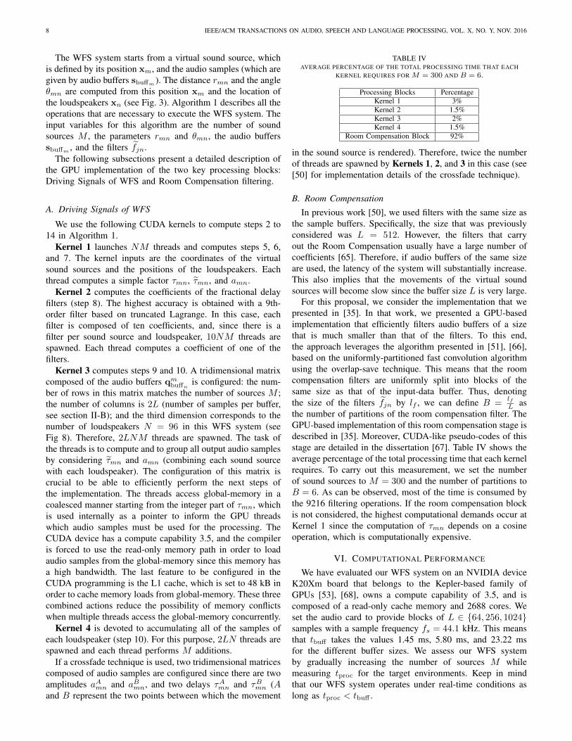
TABLE IVAVERAGE PERCENTAGE OF THE TOTAL PROCESSING TIME THAT EACH
in the sound source is rendered). Therefore, twice the numberof threads are spawned by Kernels 1, 2, and 3 in this case (see[50] for implementation details of the crossfade technique).
B. Room Compensation
In previous work [50], we used filters with the same size asthe sample buffers. Specifically, the size that was previouslyconsidered was L = 512. However, the filters that carryout the Room Compensation usually have a large number ofcoefficients [65]. Therefore, if audio buffers of the same sizeare used, the latency of the system will substantially increase.This also implies that the movements of the virtual soundsources will become slow since the buffer size L is very large.
For this proposal, we consider the implementation that wepresented in [35]. In that work, we presented a GPU-basedimplementation that efficiently filters audio buffers of a sizethat is much smaller than that of the filters. To this end,the approach leverages the algorithm presented in [51], [66],based on the uniformly-partitioned fast convolution algorithmusing the overlap-save technique. This means that the roomcompensation filters are uniformly split into blocks of thesame size as that of the input-data buffer. Thus, denotingthe size of the filters fjn by lf , we can define B =
lfL as
the number of partitions of the room compensation filter. TheGPU-based implementation of this room compensation stage isdescribed in [35]. Moreover, CUDA-like pseudo-codes of thisstage are detailed in the dissertation [67]. Table IV shows theaverage percentage of the total processing time that each kernelrequires. To carry out this measurement, we set the numberof sound sources to M = 300 and the number of partitions toB = 6. As can be observed, most of the time is consumed bythe 9216 filtering operations. If the room compensation blockis not considered, the highest computational demands occur atKernel 1 since the computation of τmn depends on a cosineoperation, which is computationally expensive.
VI. COMPUTATIONAL PERFORMANCE
We have evaluated our WFS system on an NVIDIA deviceK20Xm board that belongs to the Kepler-based family ofGPUs [53], [68], owns a compute capability of 3.5, and iscomposed of a read-only cache memory and 2688 cores. Weset the audio card to provide blocks of L ∈ {64, 256, 1024}samples with a sample frequency fs = 44.1 kHz. This meansthat tbuff takes the values 1.45 ms, 5.80 ms, and 23.22 msfor the different buffer sizes. We assess our WFS systemby gradually increasing the number of sources M whilemeasuring tproc for the target environments. Keep in mindthat our WFS system operates under real-time conditions aslong as tproc < tbuff .
BELLOCH et al.: GPU-BASED DYNAMIC WAVE FIELD SYNTHESIS 9
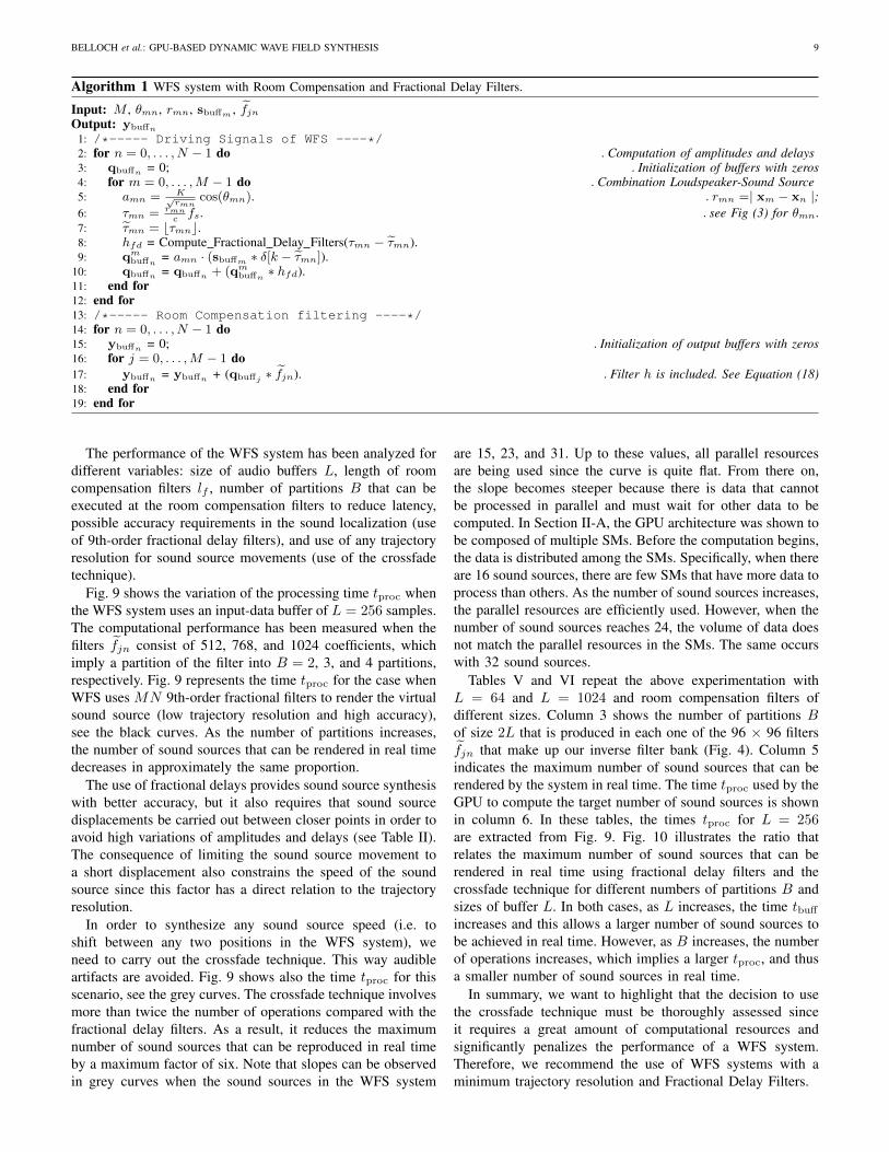
Algorithm 1 WFS system with Room Compensation and Fractional Delay Filters.
Input: M , θmn, rmn, sbuffm , fjnOutput: ybuffn
1: /*----- Driving Signals of WFS ----*/2: for n = 0, . . . , N − 1 do .Computation of amplitudes and delays3: qbuffn = 0; .Initialization of buffers with zeros4: for m = 0, . . . ,M − 1 do .Combination Loudspeaker-Sound Source5: amn = K√
∗ hfd).11: end for12: end for13: /*----- Room Compensation filtering ----*/14: for n = 0, . . . , N − 1 do15: ybuffn = 0; .Initialization of output buffers with zeros16: for j = 0, . . . ,M − 1 do17: ybuffn = ybuffn + (qbuffj ∗ fjn). .Filter h is included. See Equation (18)18: end for19: end for
The performance of the WFS system has been analyzed fordifferent variables: size of audio buffers L, length of roomcompensation filters lf , number of partitions B that can beexecuted at the room compensation filters to reduce latency,possible accuracy requirements in the sound localization (useof 9th-order fractional delay filters), and use of any trajectoryresolution for sound source movements (use of the crossfadetechnique).
Fig. 9 shows the variation of the processing time tproc whenthe WFS system uses an input-data buffer of L = 256 samples.The computational performance has been measured when thefilters fjn consist of 512, 768, and 1024 coefficients, whichimply a partition of the filter into B = 2, 3, and 4 partitions,respectively. Fig. 9 represents the time tproc for the case whenWFS uses MN 9th-order fractional filters to render the virtualsound source (low trajectory resolution and high accuracy),see the black curves. As the number of partitions increases,the number of sound sources that can be rendered in real timedecreases in approximately the same proportion.
The use of fractional delays provides sound source synthesiswith better accuracy, but it also requires that sound sourcedisplacements be carried out between closer points in order toavoid high variations of amplitudes and delays (see Table II).The consequence of limiting the sound source movement toa short displacement also constrains the speed of the soundsource since this factor has a direct relation to the trajectoryresolution.
In order to synthesize any sound source speed (i.e. toshift between any two positions in the WFS system), weneed to carry out the crossfade technique. This way audibleartifacts are avoided. Fig. 9 shows also the time tproc for thisscenario, see the grey curves. The crossfade technique involvesmore than twice the number of operations compared with thefractional delay filters. As a result, it reduces the maximumnumber of sound sources that can be reproduced in real timeby a maximum factor of six. Note that slopes can be observedin grey curves when the sound sources in the WFS system
are 15, 23, and 31. Up to these values, all parallel resourcesare being used since the curve is quite flat. From there on,the slope becomes steeper because there is data that cannotbe processed in parallel and must wait for other data to becomputed. In Section II-A, the GPU architecture was shown tobe composed of multiple SMs. Before the computation begins,the data is distributed among the SMs. Specifically, when thereare 16 sound sources, there are few SMs that have more data toprocess than others. As the number of sound sources increases,the parallel resources are efficiently used. However, when thenumber of sound sources reaches 24, the volume of data doesnot match the parallel resources in the SMs. The same occurswith 32 sound sources.
Tables V and VI repeat the above experimentation withL = 64 and L = 1024 and room compensation filters ofdifferent sizes. Column 3 shows the number of partitions Bof size 2L that is produced in each one of the 96 × 96 filtersfjn that make up our inverse filter bank (Fig. 4). Column 5indicates the maximum number of sound sources that can berendered by the system in real time. The time tproc used by theGPU to compute the target number of sound sources is shownin column 6. In these tables, the times tproc for L = 256are extracted from Fig. 9. Fig. 10 illustrates the ratio thatrelates the maximum number of sound sources that can berendered in real time using fractional delay filters and thecrossfade technique for different numbers of partitions B andsizes of buffer L. In both cases, as L increases, the time tbuff
increases and this allows a larger number of sound sources tobe achieved in real time. However, as B increases, the numberof operations increases, which implies a larger tproc, and thusa smaller number of sound sources in real time.
In summary, we want to highlight that the decision to usethe crossfade technique must be thoroughly assessed sinceit requires a great amount of computational resources andsignificantly penalizes the performance of a WFS system.Therefore, we recommend the use of WFS systems with aminimum trajectory resolution and Fractional Delay Filters.
10 IEEE/ACM TRANSACTIONS ON AUDIO, SPEECH AND LANGUAGE PROCESSING, VOL. X, NO. Y, NOV. 2016
Audio Samples2L
M
N
Audio Samples2L
M
10 coefficients froma fractional delay filter
M
N
M
N
M
N
Amplitudefactors
Delayfactors
KERNEL 3
2LNM cuda threads are launched
KERNEL 4
2LN cuda threads are launched
N
Audio Samples2L
Fig. 8. Kernel 3 and Kernel 4 perform the computation of the driving signals of a WFS system.
Fig. 9. Performance of the WFS system using a buffer size of L = 256samples for three room compensation filter lengths: 512, 768, and 1024.The black curves synthesizes the virtual sound sources by using NM 9th-order fractional delay filters and the grey curves synthesizes the virtual soundsources by using the crossfade technique.
VII. CONCLUSION
The use of GPUs in large-scale audio systems is gainingmomentum. One of the audio systems that requires a greatamount of processing power is Wave Field Synthesis withroom compensation and moving virtual sound sources. In thispaper, we have analyzed how a state-of-the-art GPU can beused to develop a high-performance solution for this problem.
TABLE VMAXIMUM PERFORMANCE THAT THE WFS SYSTEM ACHIEVES WHEN THE
SOUND SOURCES ARE SYNTHESIZED USING 9-TH ORDER FRACTIONALDELAY FILTERS. BUFFER SIZES OF L = 64 AND L = 1024 AND
DIFFERENT SIZE OF ROOM COMPENSATION FILTERS lf ARE EVALUATED.
In terms of accuracy of the sound source localization, wehave studied the impact of synthesizing a moving sound sourcevia time-varying fractional delay filters. Our results show thatfilters of this kind offer the best approach for the theoretical
BELLOCH et al.: GPU-BASED DYNAMIC WAVE FIELD SYNTHESIS 11
1
1 -
2 -
3 -
4 -
5 -
6 -
7 -L=64L=256L=1024
Ratio Max Sound Sources in Real Time: Fractional Delay Filters vs Crossfade
Number of Partitions B2 3 4 5 6 1 2 3 4 5 6 1 2 3 4 5 6
Fig. 10. Ratio that relates the maximum number of sound sources that can berendered in real time using fractional delay filters and crossfade for differentnumber of blocks B and sizes of buffer L.
TABLE VIMAXIMUM PERFORMANCE THAT THE WFS SYSTEM ACHIEVES WHEN THESOUND SOURCES ARE SYNTHESIZED USING THE CROSSFADE TECHNIQUE.BUFFER SIZES OF L = 64 AND L = 1024 AND DIFFERENT SIZE OF ROOM
WFS signal. Specifically, the best results were obtained withthe truncated Lagrange interpolation technique.
When shifting a virtual sound source between two points,audible non-linear artifacts can appear due to the large changesin amplitudes and delays that must be rendered by the WFSsystem. To avoid this, we have also evaluated the WFS systemusing the crossfade technique, which more than doubles thenumber of operations in comparison with the use of fractionaldelay filters.
In addition, we have improved our previous GPU-basedimplementation by filtering audio buffers that are smallerthan the size of room compensation filters. This allows thedesign of room compensation filters with a large number ofcoefficients and thus higher spatial sound quality. In order toimplement the system efficiently, we have convolved the WFSpre-equalization filter h with the room compensation filtersbefore starting the real-time processing.
Finally, our implementation exploits the resources of GPUswith Kepler architecture, which can currently be found in new-generation mobile devices such as modern tablets.
GPU code of this work and instructions for compil-ing it together with multimedia materials are available athttp://www.gtac.upv.es/enlaces.asp.
ACKNOWLEDGMENT
This work was initiated when Dr. Jose A. Belloch was avisiting postdoctoral researcher at Aalto University in 2015and was finished during his stay at Universidad Complutensede Madrid in 2016.
REFERENCES
[1] S. Spors, H. Wierstorf, A. Raake, F. Melchior, M. Frank, and F. Zotter,“Spatial sound with loudspeakers and its perception: A review of thecurrent state,” Proc. IEEE, vol. 101, no. 9, pp. 1920–1938, Sept. 2013.
[2] A. Berkhout, “A holographic approach to acoustic control,” J. AudioEng. Soc., vol. 36, no. 12, pp. 977–995, Dec. 1988.
[3] A. Berkhout, D. de Vries, and P. Vogel, “Acoustic control by wave fieldsynthesis,” J. Acoust. Soc. Am., vol. 93, no. 5, pp. 2764–2778, May1993.
[4] P. Vogel, “Application of Wave Field Synthesis in Room Acoustics,”Ph.D. dissertation, Delft University of Technology, Delft, Netherlands,1993.
[5] E. Start, “Direct sound enhancement by Wave Field Synthesis,” Ph.D.dissertation, Delft University of Technology, Delft, Netherlands, 1997.
[6] E. Verheijen, “Sound reproduction by Wave Field Synthesis,” Ph.D.dissertation, Delft University of Technology, Delft, Netherlands, 1997.
[7] J.-J. Sonke, “Variable acoustics by Wave Field Synthesis,” Ph.D. disser-tation, Delft University of Technology, Delft, Netherlands, 2000.
[8] E. Hulsebos, “Auralization using Wave Field Synthesis,” Ph.D. disser-tation, Delft University of Technology, Delft, Netherlands, 2004.
[9] E. Hulsebos, D. de Vries, and E. Bourdillat, “Improved microphone arrayconfigurations for auralization of sound fields by Wave-Field Synthesis,”J. Audio Eng. Soc., vol. 50, no. 10, pp. 779–790, Oct. 2002.
[10] S. Spors, H. Buchner, and R. Rabenstein, “Efficient active listening roomcompensation for Wave Field Synthesis,” in Proc. 116th AES Conv.,Berlin, Germany, May 2004.
[11] J. J. Lopez, A. Gonzalez, and L. Fuster, “Room compensation in wavefield synthesis by means of multichannel inversion,” in Proc. IEEEWorkshop Appl. Signal Process. Audio Acoust. (WASPAA), New Paltz,NY, USA, Oct. 2005, pp. 146–149.
[12] T. I. Laakso, V. Valimaki, M. Karjalainen, and U. K. Laine, “Splittingthe unit delay: Tools for fractional delay filter design,” IEEE SignalProcess. Mag., vol. 13, no. 1, pp. 30–60, Jan. 1996.
[13] M. Karjalainen, T. Paatero, J. Pakarinen, and V. Valimaki, “Specialdigital filters for audio reproduction,” in Proc. 32nd AES Conf., Hillerød,Denmark, Sept. 2007.
[14] J. Dattorro, “Effect design—Part 2: Delay-line modulation and chorus,”J. Audio Eng. Soc., vol. 45, no. 10, pp. 764–788, Oct. 1997.
[15] U. Zolzer, DAFX: Digital Audio Effects, 2nd ed. Chichester, UK: Wiley,2011.
[16] V. Valimaki, “Discrete-time modeling of acoustic tubes using fractionaldelay filters,” Ph.D. dissertation, Helsinki Univ. Tech., Espoo, Finland,Dec. 1995.
[17] V. Valimaki, J. Pakarinen, C. Erkut, and M. Karjalainen, “Discrete-time modelling of musical instruments,” Reports on Progress in Physics,vol. 69, no. 1, pp. 1–78, Jan. 2006.
[18] A. Franck, A. Grafe, T. Korn, and M. Strauss, “Reproduction of movingsound sources by wave field synthesis: an analysis of artifacts.” in Proc.32nd AES Conf., Hillerød, Denmark, Sept. 2007.
[19] A. Franck, K. Brandenburg, and U. Richter, “Efficient delay interpolationfor Wave Field Synthesis,” in Proc. 125th AES Conv., San Francisco,CA, USA, Oct. 2008.
[20] A. Franck, “Efficient algorithms for arbitrary sample rate conversionwith application to wave field synthesis,” Ph.D. dissertation, TechnicalUniversity of Ilmenau, Ilmenau, Germany, 2012.
[21] J. Ahrens, M. Gier, and S. Spors, “Perceptual assessment of delayaccuracy and loudspeaker misplacement in wave field synthesis,” inProc. 128th AES Conv., London, UK, May 2010.
[22] C. Salvador, “Wave field synthesis using fractional order systems andfractional delays,” in Proc. 128th AES Conv., London, UK, May 2010.
[23] F. Winter and S. Spors, “On fractional delay interpolation for local wavefield synthesis,” in Proc. European Signal Process. Conf. (EUSIPCO),Budapest, Hungary, Sept. 2016, pp. 2415–2419.
12 IEEE/ACM TRANSACTIONS ON AUDIO, SPEECH AND LANGUAGE PROCESSING, VOL. X, NO. Y, NOV. 2016
[24] L. Savioja, “Real-time 3D finite-difference time-domain simulation oflow- and mid-frequency room acoustics,” in Proc. Int. Conf. DigitalAudio Effects (DAFX), Graz, Austria, Sept. 2010, pp. 1–8.
[25] A. Southern, D. Murphy, G. Campos, and P. Dias, “Finite differenceroom acoustic modelling on a general purpose graphics processing unit,”in Proc. 128th AES Conv., London, UK, May 2010.
[26] C. J. Webb and S. Bilbao, “Computing room acoustics with CUDA—3D FDTD schemes with boundary losses and viscosity,” in Proc. IEEEInt. Conf. Acoust. Speech Signal Process. (ICASSP), Prague, CzechRepublic, May 2011, pp. 317–320.
[27] B. Hamilton and C. J. Webb, “Room acoustics modelling using GPU-accelerated finite difference and finite volume methods on a face-centered cubic grid,” in Proc. Int. Conf. Digital Audio Effects (DAFX),Maynooth, Ireland, Sept. 2013, pp. 1–8.
[28] L. Savioja, V. Valimaki, and J. O. Smith, “Real-time additive synthesiswith one million sinusoids using a GPU,” in Proc. 128th AES Conv.,London, UK, May 2010.
[29] ——, “Audio signal processing using graphics processing units,” J.Audio Eng. Soc., vol. 59, no. 1–2, pp. 3–19, Jan.-Feb. 2011.
[30] S. Bilbao and C. J. Webb, “Physical modeling of timpani drums in 3Don GPGPUs,” J. Audio Eng. Soc., vol. 61, no. 10, pp. 737–748, Oct.2013.
[31] R. Bradford, J. Ffitch, and R. Dobson, “Real-time sliding phase vocoderusing a commodity GPU,” in Proc. Int. Computer Music Conf. (ICMC),Huddersfield, UK, Aug. 2011, pp. 587–590.
[32] J. Lorente, G. Pinero, A. Vidal, J. Belloch, and A. Gonzalez, “Parallelimplementations of beamforming design and filtering for microphone ar-ray applications,” in Proc. European Signal Process. Conf. (EUSIPCO),Barcelona, Spain, Aug. 2011, pp. 501–505.
[33] N. Tsingos, W. Jiang, and I. Williams, “Using programmable graphicshardware for acoustics and audio rendering,” J. Audio Eng. Soc., vol. 59,no. 9, pp. 628–646, Sept. 2011.
[34] J. A. Belloch, M. Ferrer, A. Gonzalez, F. Martinez-Zaldivar, and A. M.Vidal, “Headphone-based virtual spatialization of sound with a GPUaccelerator,” J. Audio Eng. Soc., vol. 61, no. 7/8, pp. 546–561, Jul.-Aug.2013.
[35] J. A. Belloch, A. Gonzalez, F. Martinez-Zaldivar, and A. M. Vidal, “Mul-tichannel massive audio processing for a generalized crosstalk cancel-lation and equalization application using GPUs,” Integrated Computer-Aided Engineering, vol. 20, no. 2, pp. 169–182, Apr. 2013.
[36] J. A. Belloch, B. Bank, L. Savioja, A. Gonzalez, and V. Valimaki,“Multi-channel IIR filtering of audio signals using a GPU,” in Proc.IEEE Int. Conf. Acoust. Speech Signal Process. (ICASSP), Florence,Italy, May 2014, pp. 6692–6696.
[37] J. A. Belloch, J. Parker, L. Savioja, A. Gonzalez, and V. Valimaki,“Dynamic range reduction of audio signals using multiple allpassfilters on a GPU accelerator,” in Proc. European Signal Process. Conf.(EUSIPCO), Lisbon, Portugal, Sept. 2014, pp. 890–894.
[38] M. Schneider, F. Schuh, and W. Kellermann, “The generalizedfrequency-domain adaptive filtering algorithm implemented on a GPUfor large-scale multichannel acoustic echo cancellation,” in Proc. SpeechCommunication; 10. ITG Symposium., Braunschweig, Germany, Sept.2012, pp. 1–4.
[39] J. Lorente, A. Gonzalez, M. Ferrer, J. A. Belloch, M. De Diego,G. Pinero, and A. M. Vidal, “Active noise control using GraphicsProcessing Units,” in Proc. Int. Congr. Sound Vibr., Vilnius, Lithuania,July 2012, pp. 1 – 8.
[40] J. Lorente, M. Ferrer, M. De Diego, and A. Gonzalez, “GPU imple-mentation of multichannel adaptive algorithms for local active noisecontrol,” IEEE Trans. Audio Speech Lang. Process., vol. 22, no. 11, pp.1624–1635, Nov. 2014.
[41] L. Romoli, P. Peretti, S. Cecchi, L. Palestini, and F. Piazza, “Real-timeimplementation of wave field synthesis for sound reproduction systems,”in Proc. IEEE Asia Pacific Conf. Circ. Syst. (APCCAS), Kuala Lumpur,Malaysia, Nov. 2008, pp. 430–433.
[42] D. Theodoropoulos, G. Kuzmanov, and G. Gaydadjiev, “A minimalisticarchitecture for reconfigurable WFS-based immersive-audio,” in Proc.2010 Int. Conf. Reconfigurable Computing and FPGAs (ReConFig),Cancun, Mexico, Dec. 2010.
[43] ——, “Multi-core platforms for beamforming and Wave Field Synthe-sis,” IEEE Trans. Multimedia, vol. 3, no. 2, pp. 235–245, Apr. 2011.
[44] R. Ranjan and W. S. Gan, “Fast and efficient real-time GPU basedimplementation of wave field synthesis,” in Proc. IEEE Int. Conf. Acoust.Speech Signal Process. (ICASSP), Florence, Italy, May 2014, pp. 7550–7554.
[45] A. Lattanzi, E. Ciavattini, S. Cecchi, L. Romoli, and F. Ferrandi, “Real-time implementation of Wave Field Synthesis on NU-Tech framework
using CUDA technology,” in Proc. 128th AES Conv., London, UK, May2010.
[46] A. Lattanzi, F. Bettarelli, and S. Cecchi, “NU-Tech: The entry tool ofthe hArtes toolchain for algorithms design,” in Proc. 124th AES Conv.,Amsterdam, The Netherlands, May 2008.
[50] J. A. Belloch, M. Ferrer, A. Gonzalez, J. Lorente, and A. M. Vidal,“GPU-based WFS systems with mobile virtual sound sources and roomcompensation,” in Proc. 52nd AES Conf., Guildford, UK, Sept. 2013.
[51] B. D. Kulp, “Digital equalization using Fourier transform techniques,”in Proc. 85th AES Conv., Los Angeles, CA, USA, Nov. 1988.
[52] M. J. Flynn, “Some computer organizations and their effectiveness,”IEEE Trans. Comput., vol. 21, no. 9, pp. 948–960, Sep. 1972.
[53] “Nvidia CUDA Developer Zone,”https://developer.nvidia.com/cuda-zone, (accessed 2016 Oct. 11).
[54] “Audio and Communications Signal Processing Group at UniversitatPolitecnica de Valencia,” http://www.gtac.upv.es.
[55] M. M. Boone, E. N. G. Verheijen, and P. F. Van Tol, “Spatial sound-field reproduction by wave-field synthesis,” J. Audio Eng. Soc., vol. 43,no. 12, pp. 1003–1012, Dec. 1995.
[56] S. Spors, A. Kuntz, and R. Rabenstein, “An approach to listening roomcompensation with wave field synthesis,” in Proc. 24th AES Conf., Banff,Canada, May 2003.
[57] S. Spors and J. Ahrens, “Analysis and improvement of pre-equalizationin 2.5-dimensional wave field synthesis,” in Proc. 128th AES Conv.,London, UK, May 2010.
[58] L. Fuster, J. J. Lopez, A. Gonzalez, and P. Faus, “Time and frequencydomain room compensation applied to wave field synthesis,” in Proc.Int. Conf. Digital Audio Effects (DAFX), Madrid, Spain, Sept. 2005, pp.1–6.
[59] O. Kirkeby, P. A. Nelson, H. Hamada, and F. Orduna-Bustamante,“Fast deconvolution of multichannel systems using regularization,” IEEETrans. Speech Audio Process., vol. 6, no. 2, pp. 189–194, Mar. 1998.
[60] M. Miyoshi and Y. Kaneda, “Inverse filtering of room acoustics,” IEEETrans. Acoust, Speech Signal Process., vol. 36, no. 2, pp. 145–152, Mar.1988.
[61] M. Gasparini, P. Peretti, S. Cecchi, L. Romoli, and F. Piazza, “Real-timereproduction of moving sound sources by wave field synthesis: Objectiveand subjective quality evaluation,” in Proc. 130th AES Conv., London,UK, May 2011.
[62] V. Valimaki and A. Haghparast, “Fractional delay filter design based ontruncated Lagrange interpolation,” IEEE Signal Process. Lett., vol. 14,no. 11, pp. 816–819, Nov. 2007.
[63] E. Hermanowicz, “Explicit formulas for weighting coefficients of max-imally flat tunable FIR delayers,” Electron. Lett., vol. 28, no. 2, pp.1936–1937, Sept. 1992.
[64] H. David, The Method of Paired Comparisons. London, UK: Griffin,1988.
[65] H. Kuttruff, Room Acoustics, 5th ed. Abingdon, UK: Taylor & Francis,Oct. 2000.
[66] F. Wefers and M. Vorlander, “Optimal filter partitions for real-timeFIR filtering using uniformly-partitioned FFT-based convolution in thefrequency-domain,” in Proc. Int. Conf. Digital Audio Effects (DAFX),Paris, France, Sept. 2011, pp. 155–161.
[67] J. A. Belloch, “Performance Improvement of Multichannel Audio byGraphics Processing Units,” Ph.D. dissertation, Universitat Politecnicade Valencia, Valencia, Spain, 2014.
[68] CUDA Programming: A Developer’s Guide to Parallel Computing withGPUs, 1st ed. San Francisco, CA, USA: Morgan Kaufmann PublishersInc., 2013.
BELLOCH et al.: GPU-BASED DYNAMIC WAVE FIELD SYNTHESIS 13
Jose A. Belloch received the degree in Telecommu-nications Engineering in 2007, a Master’s degree inParallel and Distributed Computing in 2010 and aPh.D. degree in Computer Science in 2014. All ofthem at the Universitat Politecnica de Valencia. HisPhD thesis was recognized with the ExtraordinaryPhD Thesis Award. Between 2010 and 2014 hewas a PhD grant holder of the Spanish Ministry ofScience and Innovation. Between 2014 and 2016 heheld a postdoctoral position at the HPC&A groupof the Universitat Jaume I de Castellon de la Plana
(Spain), where he was involved in two EU projects (EXA2GREEN andINTERTWinE). In July 2016 he was awarded with a Post-Doctoral Fellowshipof the Regional Government of Valencia in order to carry out researchat University Jaume I de Castellon in collaboration with the UniversidadComplutense de Madrid, Spain. He was a visiting researcher at Departmentof Signal Processing and Acoustics, Aalto University School of ElectricalEngineering (Espoo, Finland) as a pre-doc researcher in 2013 and as apost-doc researcher in 2015. He carried out an internship at Department ofMeasurement and Information Systems, Budapest University of Technologyand Economics, Budapest, Hungary. His research interests are centered inapplying the new parallel architectures into signal processing algorithms. Hehas developed several real-time audio applications related with multichannelmassive filtering, binaural sound, wave field synthesis systems, and soundsource localization using General Purpose Graphic Processing Units and ARMarchitectures.
Alberto Gonzalez works as Professor at the Univer-sitat Politecnica de Valencia (UPV), Spain. He at-tended the Universitat Politecnica Catalunya, Spain,where he graduated in Telecommunications En-gineering with highest honours. In 1997 he wasawarded a Doctorate (PhD), magna cum laude, fromthe UPV. During 1995 he worked as a visitingresearcher in the Institute of Sound and VibrationResearch (ISVR) at the University of Southampton,UK. Currently, he is the head of the research groupin Audio and Communications Digital Signal Pro-
cessing.Alberto Gonzalez has published over 100 papers in international technical
journals and renowned conferences in the fields of signal processing andapplied acoustics. He is a member of the senate of the UPV and servesas Dean of the Telecommunications Engineering School since June 2012.His current research interests include optimization of computation methodsfor detection and decoding in digital communications and distributed soundsignal processing.
Enrique S. Quintana-Ortı received his bachelorand Ph.D. degrees in Computer Sciences from theUniversitat Politecnica de Valencia (Spain) in 1992and 1996. Currently he is professor in ComputerArchitecture in the Universitat Jaume I de Castellon(Spain). He has published more than 100 papersin international conferences and journals, and hascontributed to software libraries like SLICOT andlibflame. His research interests include parallel pro-gramming, linear algebra, power consumption, aswell as advanced architectures and hardware accel-
erators.
Miguel Ferrer graduated in TelecommunicationsEngineering in the year 2000 at the UniversitatPolitecnica de Valencia (UPV), Spain. He was col-laborating with the Audio and Communications Sig-nal Processing Group (GTAC) since a year before,performing a six months research stay in the Institutode Investigacion Aplicada al Automovil, Tarragona,Spain (Automobile Applied Research Institute). Sub-sequently, he was awarded several grants offeredboth by the Communications Department of theUPV and by the Research, Development and In-
novation Vice-Chancellery of the same university, enabling him to start hisDoctorate studies and to collaborate in different research projects within theGTAC. During this period he has authored or co-authored over sixty papersrelated with signal processing in renowned journals and conferences. Since2005 he works as an assistant lecturer in the Communications Department ofthe UPV. His research activity is focused on the study of adaptive algorithmsand its application to audio digital processing and noise active control, asubject about which he developed his doctoral thesis.
Vesa Valimaki (S’90–M’92–SM’99–F’15) receivedthe M.Sc. in Technology and the Doctor of Sciencein Technology degrees in electrical engineering fromthe Helsinki University of Technology (TKK), Es-poo, Finland, in 1992 and 1995, respectively.
He was a Postdoctoral Research Fellow at theUniversity of Westminster, London, UK, in 1996.In 1997–2001, he was a Senior Assistant at TKK.In 2001–2002, he was a Professor of signal process-ing at the Pori unit of the Tampere University ofTechnology, Pori, Finland. In 2006–2007, he was the
Head of the TKK Laboratory of Acoustics and Audio Signal Processing. In2008–2009, he was a Visiting Scholar at Stanford University, CA, USA. Heis currently a Professor of audio signal processing at Aalto University, Espoo,Finland. His research interests are related to signal processing techniques inaudio and music technology.
Prof. Valimaki is a Fellow of the Audio Engineering Society and a LifeMember of the Acoustical Society of Finland. In 2007–2013 he was a Memberof the Audio and Acoustic Signal Processing Technical Committee of theIEEE Signal Processing Society and is currently an Associate Member. Heis a Founding Member of the EURASIP Special Area Team in acoustic,sound and music signal processing (2015–). He served as an AssociateEditor of the IEEE SIGNAL PROCESSING LETTERS in 2005–2009 and of theIEEE TRANSACTIONS ON AUDIO, SPEECH AND LANGUAGE PROCESSINGin 2007–2011. He was in the Editorial Board of the Research Letters in SignalProcessing, the Journal of Electrical and Computer Engineering, and TheScientific World Journal. He was the Lead Guest Editor of a special issueof the IEEE SIGNAL PROCESSING MAGAZINE in 2007 and of a specialissue of the IEEE TRANSACTIONS ON AUDIO, SPEECH AND LANGUAGEPROCESSING in 2010. In 2015, he was a Guest Editor of the special issue ofthe IEEE SIGNAL PROCESSING MAGAZINE on signal processing techniquesfor assisted listening. In 2015–2016, he was the Lead Guest Editor of thespecial issue of Applied Sciences on audio signal processing. In 2008, hewas the General Chair of DAFX-08, the 11th International Conference onDigital Audio Effects. He has been a Senior Area Editor of the IEEE/ACMTRANSACTIONS ON AUDIO, SPEECH AND LANGUAGE PROCESSING since2015.