32
BeoLab Transmitter 1 Type 1505 - 1513 Installation Guide English - version 1.2
BeoLab Transmitter 1Type 1505 - 1513
Installation GuideEnglish - version 1.231.0
3.4
16.7
Introduction 2
IntroductionBeoLab Transmitter 1 is a stand-alone box, that enables existing music systems and TVs to connect wirelessly - within one room - to any Bang & Olufsen wireless speaker and BeoLab Receiver 1.
BeoLab Transmitter 1 works in the wireless 5 GHz U-NII band frequency spectrum. It is compliant with and will only work with all new Bang & Olufsen WiSA approved speakers and speakers connected to the BeoLab Receiver 1.
The WiSA technology offers multi-channel wireless sound performance for full surround sound setup. The benefits for the Bang & Olufsen customer are:- Eliminates cable clutter.- Offers complete flexibility when decorating your room.- Is an easy add-on to an existing wired setup.- Delivers high-quality wireless surround sound.- Offers easy 3rd party integration: mix and match your favourite audio and video components.
The BeoLab Transmitter 1 has four RJ45 inputs with Power Link / Line-in connection which have both a left and right sound channel. This means you can connect as much as 8 sound channels as input of which one can be a subwoofer in the room. In addition there is an optical stereo TOSLINK TM input (S/P-DIF) and two RCA (Line-in) for connection stereo sound channels of an audio system. Despite this the wireless technology used makes it possible to configure up to 11 wireless speakers to the sound channels as desired. One scenario may be a 7.4 setup. One switch is used to shift between a Bang & Olufsen Power Link signal in and a line-in signal from a 3rd party product (B&O INPUT YES/NO). Another switch is used for providing either a pure stereo output in two sound channels only (SUB 2.1 set to OFF) or providing the two stereo sound channels plus a third sound channel provided by the built in bass management function for the configuration of a wireless subwoofer (SUB 2.1 set to ON).
Active sources are prioritised in the following order: 1) POWER LINK; 2) TOSLINK; 3) Line-in (via RCA connectors or RJ45 connector).
With the BeoLab Transmitter 1 comes a cable cover for optimised cable management. The BeoLab Transmitter 1 is clicked onto the cable cover and can be mounted on the wall with the cables directed either up/down or sideways in any direction that is convenient for an elegant installation. The cable cover becomes an inherent part of the BeoLab Transmitter 1 and lets the solution stand out as one entity.
In a stereo setup, the speakers and the subwoofer must be connected wirelessly. In a surround sound setup, you can combine wired and wireless speakers as you like. When the BeoLab 19 has wireless connection the LP FILTER switch is set to OFF. This ensures that the BeoLab 19 emits the frequency pattern sent to the speaker and also makes the noise pattern audible when configuring the speaker setup.
How to use this installation guide 3
How to use this installation guideThis installation guide gives step by step instructions on how to:
- Mount the product,- Understand placement rules,- Connecting and setting up BeoLab Transmitter 1 with products and speakers,- Use push buttons and understand LED indications,- Use the ServiceTool and make SW update,- Understand channel patterns and use worldwide.
WarningInstallation and replacement of parts must be made by Bang & Olufsen certified installers only.
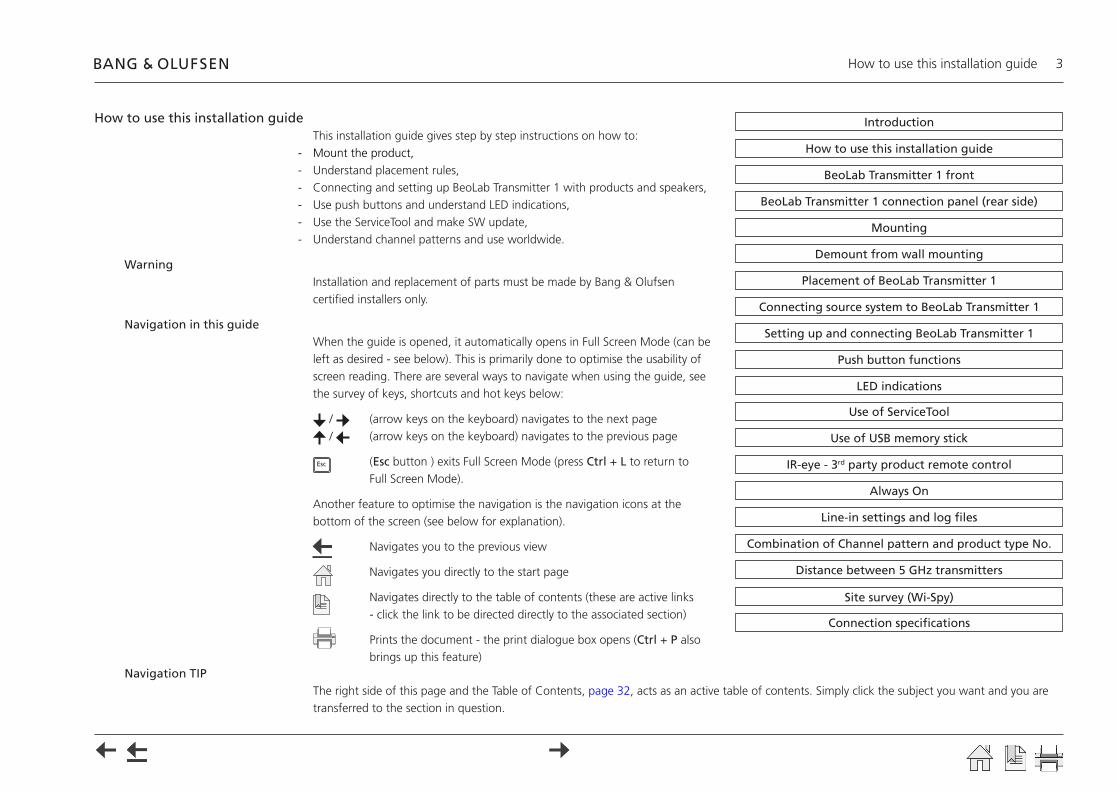
Navigation in this guideWhen the guide is opened, it automatically opens in Full Screen Mode (can be left as desired - see below). This is primarily done to optimise the usability of screen reading. There are several ways to navigate when using the guide, see the survey of keys, shortcuts and hot keys below:
/ (arrow keys on the keyboard) navigates to the next page / (arrow keys on the keyboard) navigates to the previous page
Esc (Esc button ) exits Full Screen Mode (press Ctrl + L to return to Full Screen Mode).
Another feature to optimise the navigation is the navigation icons at the bottom of the screen (see below for explanation).
Navigates you to the previous view
Navigates you directly to the start page
Navigates directly to the table of contents (these are active links - click the link to be directed directly to the associated section)
Prints the document - the print dialogue box opens (Ctrl + P also brings up this feature)
Navigation TIPThe right side of this page and the Table of Contents, page 32, acts as an active table of contents. Simply click the subject you want and you are transferred to the section in question.
Introduction
Connecting source system to BeoLab Transmitter 1
Placement of BeoLab Transmitter 1
LED indications
Site survey (Wi-Spy)
Use of USB memory stick
IR-eye - 3rd party product remote control
Always On
Line-in settings and log files
Use of ServiceTool
How to use this installation guide
Setting up and connecting BeoLab Transmitter 1
Push button functions
Combination of Channel pattern and product type No.
Distance between 5 GHz transmitters
Connection specifications
BeoLab Transmitter 1 front
BeoLab Transmitter 1 connection panel (rear side)
Demount from wall mounting
Mounting
BeoLab Transmitter 1 front - connection panel 4
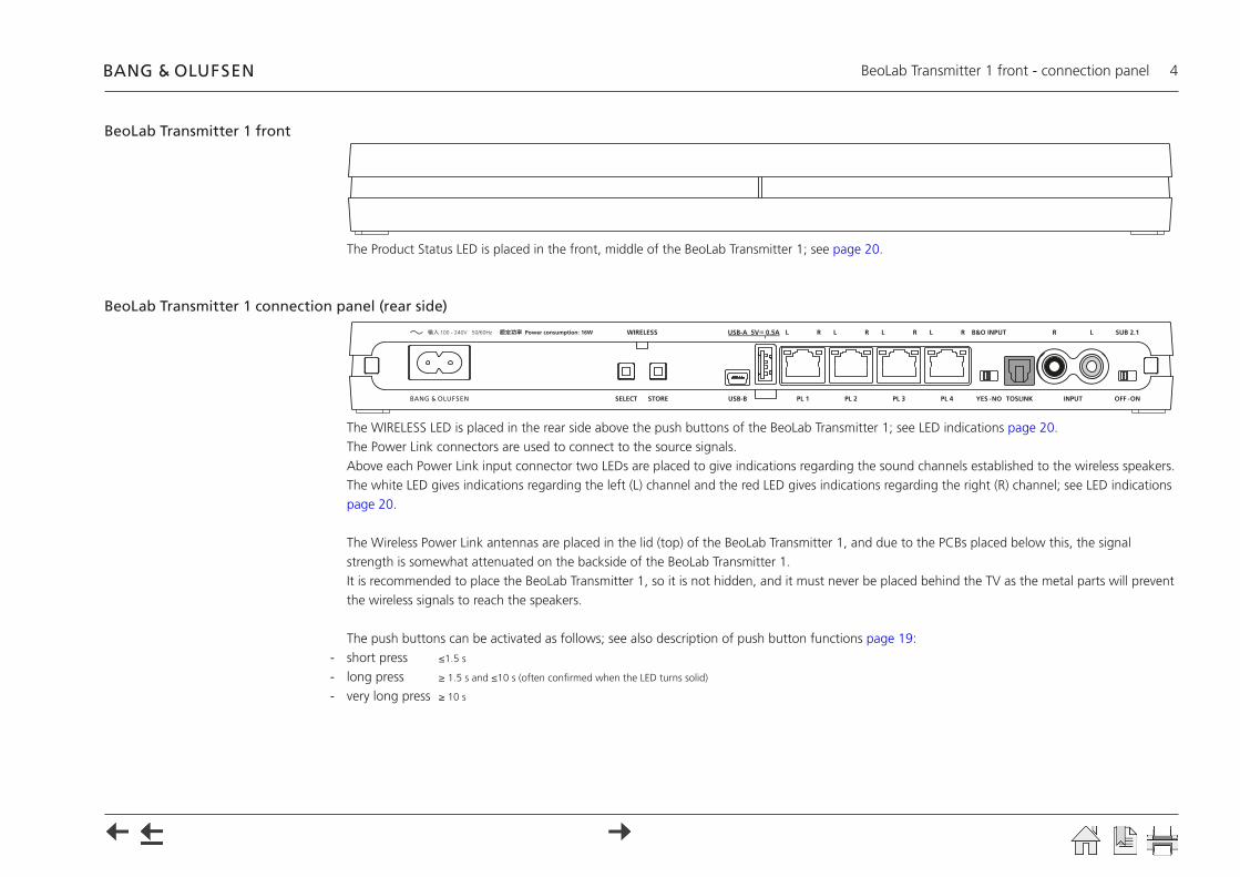
BeoLab Transmitter 1 front
The Product Status LED is placed in the front, middle of the BeoLab Transmitter 1; see page 20.
BeoLab Transmitter 1 connection panel (rear side)
The WIRELESS LED is placed in the rear side above the push buttons of the BeoLab Transmitter 1; see LED indications page 20.The Power Link connectors are used to connect to the source signals.Above each Power Link input connector two LEDs are placed to give indications regarding the sound channels established to the wireless speakers. The white LED gives indications regarding the left (L) channel and the red LED gives indications regarding the right (R) channel; see LED indications page 20.
The Wireless Power Link antennas are placed in the lid (top) of the BeoLab Transmitter 1, and due to the PCBs placed below this, the signal strength is somewhat attenuated on the backside of the BeoLab Transmitter 1.It is recommended to place the BeoLab Transmitter 1, so it is not hidden, and it must never be placed behind the TV as the metal parts will prevent the wireless signals to reach the speakers.
The push buttons can be activated as follows; see also description of push button functions page 19:- short press ≤1.5 s
- long press ≥ 1.5 s and ≤10 s (often confirmed when the LED turns solid)
- very long press ≥ 10 s
100 - 240V 50/60Hz
Mounting 5
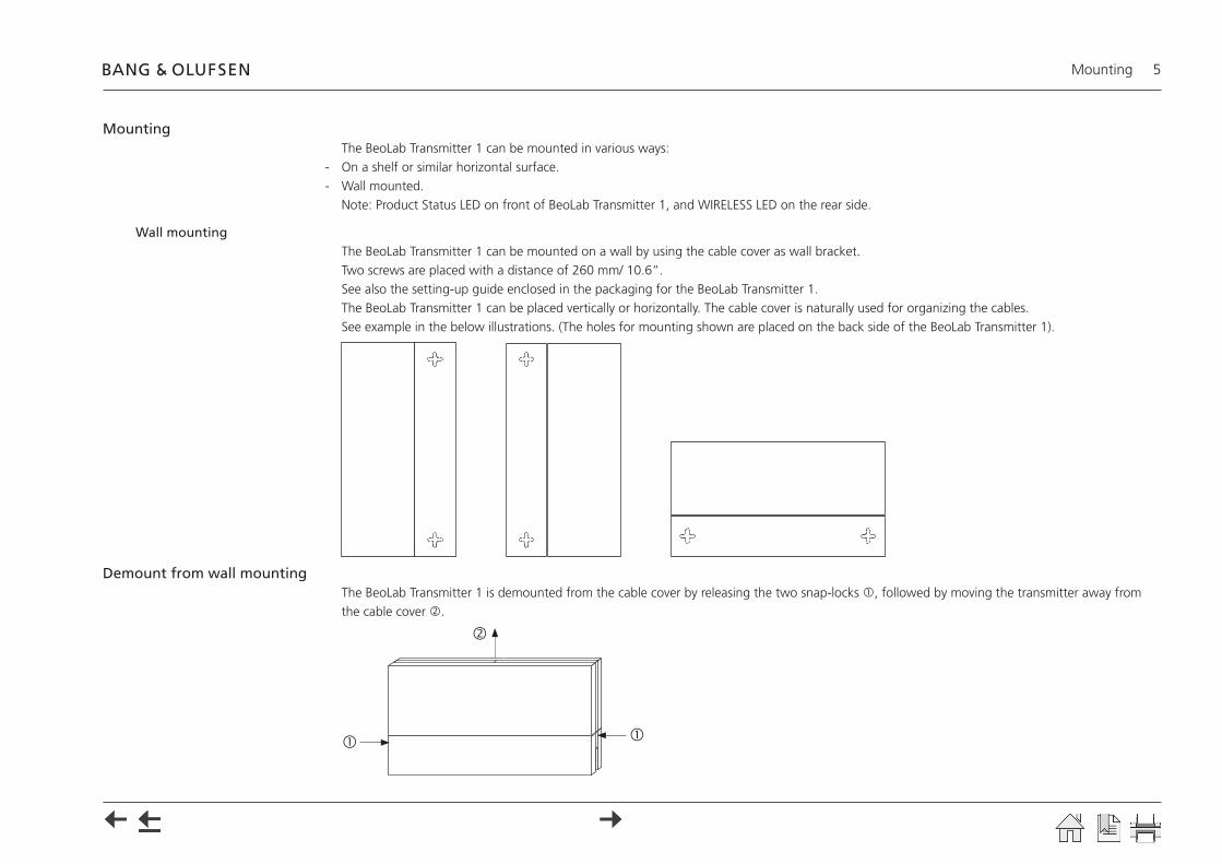
MountingThe BeoLab Transmitter 1 can be mounted in various ways:
- On a shelf or similar horizontal surface.- Wall mounted.
Note: Product Status LED on front of BeoLab Transmitter 1, and WIRELESS LED on the rear side.
Wall mountingThe BeoLab Transmitter 1 can be mounted on a wall by using the cable cover as wall bracket. Two screws are placed with a distance of 260 mm/ 10.6”. See also the setting-up guide enclosed in the packaging for the BeoLab Transmitter 1.The BeoLab Transmitter 1 can be placed vertically or horizontally. The cable cover is naturally used for organizing the cables. See example in the below illustrations. (The holes for mounting shown are placed on the back side of the BeoLab Transmitter 1).
Demount from wall mountingThe BeoLab Transmitter 1 is demounted from the cable cover by releasing the two snap-locks , followed by moving the transmitter away from the cable cover .
Placement of the Beolab Transmitter 1 6
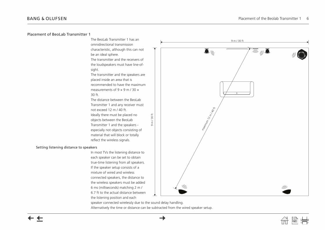
Placement of BeoLab Transmitter 1The BeoLab Transmitter 1 has an omnidirectional transmission characteristic, although this can not be an ideal sphere.The transmitter and the receivers of the loudspeakers must have line-of-sight. The transmitter and the speakers are placed inside an area that is recommended to have the maximum measurements of 9 × 9 m / 30 × 30 ft.The distance between the BeoLab Transmitter 1 and any receiver must not exceed 12 m / 40 ft.Ideally there must be placed no objects between the BeoLab Transmitter 1 and the speakers - especially not objects consisting of material that will block or totally reflect the wireless signals.
Setting listening distance to speakersIn most TVs the listening distance to each speaker can be set to obtain true-time listening from all speakers. If the speaker setup consists of a mixture of wired and wireless connected speakers, the distance to the wireless speakers must be added 6 ms (milliseconds) matching 2 m / 6.7 ft to the actual distance between the listening position and each speaker connected wirelessly due to the sound delay handling. Alternatively the time or distance can be subtracted from the wired speaker setup.
9 m / 30 ft
9 m
/ 30
ft
max
imum
12
m /
40 ft
Connecting source systems to BeoLab Transmitter 1 7
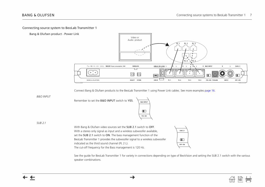
Connecting source system to BeoLab Transmitter 1
Bang & Olufsen product - Power Link
Connect Bang & Olufsen products to the BeoLab Transmitter 1 using Power Link cables. See more examples page 16.
B&O INPUTRemember to set the B&O INPUT switch to YES.
SUB 2.1With Bang & Olufsen video sources set the SUB 2.1 switch to OFF.With a stereo only signal as input and a wireless subwoofer available, set the SUB 2.1 switch to ON. The bass management function of the BeoLab Transmitter 1 provides the subwoofer signal to a wireless subwoofer indicated as the third sound channel (PL 2 L).The cut-off frequency for the Bass management is 120 Hz.
See the guide for BeoLab Transmitter 1 for variety in connections depending on type of BeoVision and setting the SUB 2.1 switch with the various speaker combinations.
100 - 240V 50/60Hz
PL 1 PL 2 PL 3
PL 4 PL 5
Video or Audio product

Connecting source systems to BeoLab Transmitter 1 8
3rd party product using Power Link as Line-in
A wireless 7.1 setup is shown as example in the above illustration. Connect 3rd party products to the BeoLab Transmitter 1 using Power Link cables. The volume of the signal must be adjusted from the source system.
B&O INPUTRemember to set the B&O INPUT switch to NO.
SUB 2.1 With a multiple sounc channel as input set the SUB 2.1 switch to OFF. With a stereo only signal as input and a wireless subwoofer available, set the SUB 2.1 switch to ON. The bass management function of the BeoLab Transmitter 1 provides the subwoofer signal to a wireless subwoofer indicated as the third sound channel (PL 2 L).The cut-off frequency for the Bass management is 120 Hz.
See the guide for BeoLab Transmitter 1 for variety in speaker combinations.
100 - 240V 50/60Hz
Surround Sound DecoderFL FR RL RR CS SWCL CR

Connecting source systems to BeoLab Transmitter 1 9
3rd party product using TOSLINK (S/P-DIF)
Connect 3rd party products to the BeoLab Transmitter 1 using a TOSLINK cable. The volume of the signal must be adjusted from the audio system.
B&O INPUTRemember to set the B&O INPUT switch to NO.In case a Bang & Olufsen product is connected additional to the 3rd party product the switch is set to YES.
SUB 2.1With a stereo only signal as input and a wireless subwoofer available, set the SUB 2.1 switch to ON. The bass management function of the BeoLab Transmitter 1 provides the subwoofer signal to a wireless subwoofer indicated as the third sound channel (PL 2 L).The cut-off frequency for the Bass management is 120 Hz.
See the guide for BeoLab Transmitter 1 for variety in speaker combinations.
100 - 240V 50/60Hz
TOSLINKOut
Audio product
Connecting source systems to BeoLab Transmitter 1 10
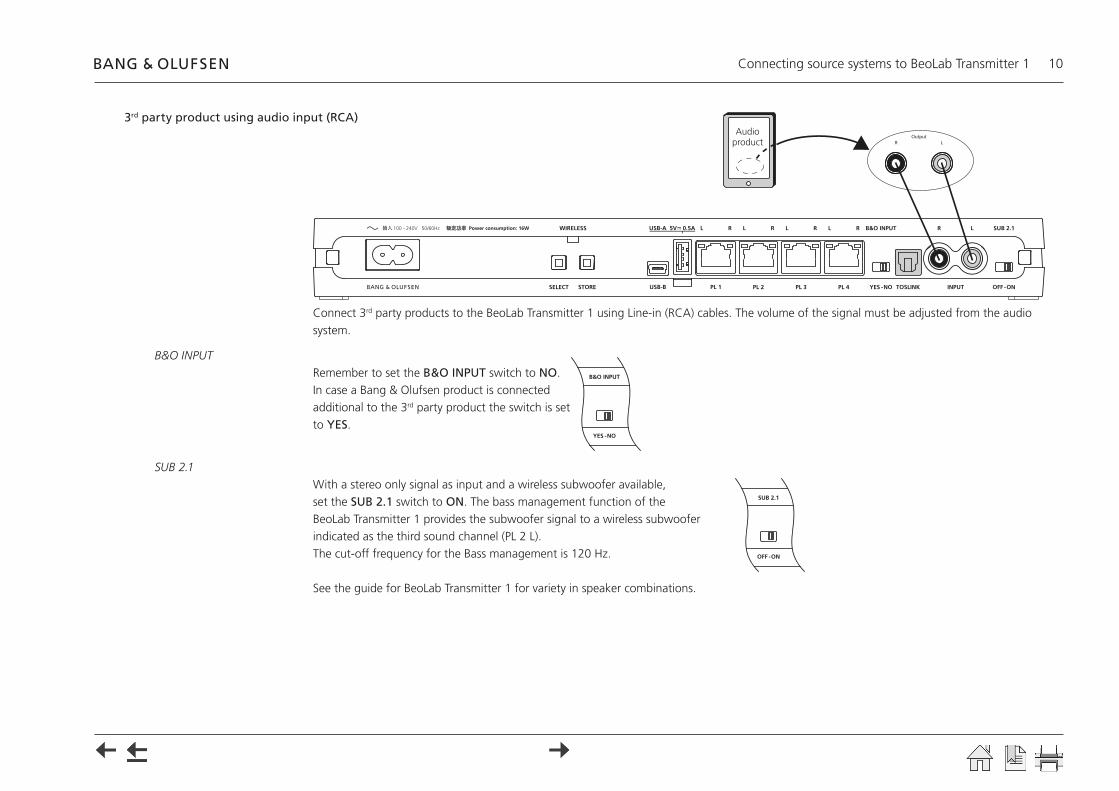
3rd party product using audio input (RCA)
Connect 3rd party products to the BeoLab Transmitter 1 using Line-in (RCA) cables. The volume of the signal must be adjusted from the audio system.
B&O INPUTRemember to set the B&O INPUT switch to NO.In case a Bang & Olufsen product is connected additional to the 3rd party product the switch is set to YES.
SUB 2.1With a stereo only signal as input and a wireless subwoofer available, set the SUB 2.1 switch to ON. The bass management function of the BeoLab Transmitter 1 provides the subwoofer signal to a wireless subwoofer indicated as the third sound channel (PL 2 L).The cut-off frequency for the Bass management is 120 Hz.
See the guide for BeoLab Transmitter 1 for variety in speaker combinations.
100 - 240V 50/60Hz
OutputR L
Audio product
Connecting source systems to BeoLab Transmitter 1 11
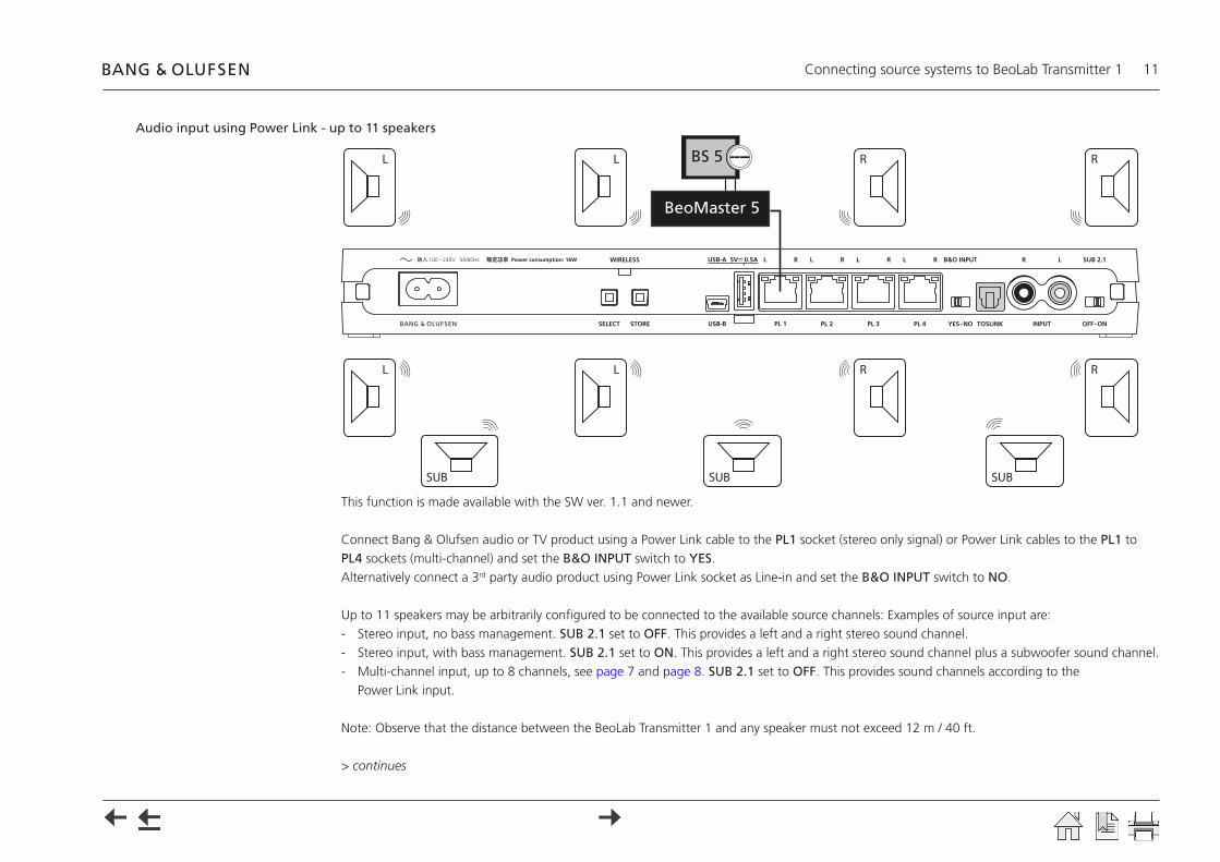
Audio input using Power Link - up to 11 speakers
This function is made available with the SW ver. 1.1 and newer.
Connect Bang & Olufsen audio or TV product using a Power Link cable to the PL1 socket (stereo only signal) or Power Link cables to the PL1 to PL4 sockets (multi-channel) and set the B&O INPUT switch to YES. Alternatively connect a 3rd party audio product using Power Link socket as Line-in and set the B&O INPUT switch to NO.
Up to 11 speakers may be arbitrarily configured to be connected to the available source channels: Examples of source input are:- Stereo input, no bass management. SUB 2.1 set to OFF. This provides a left and a right stereo sound channel.- Stereo input, with bass management. SUB 2.1 set to ON. This provides a left and a right stereo sound channel plus a subwoofer sound channel.- Multi-channel input, up to 8 channels, see page 7 and page 8. SUB 2.1 set to OFF. This provides sound channels according to the
Power Link input.
Note: Observe that the distance between the BeoLab Transmitter 1 and any speaker must not exceed 12 m / 40 ft.
> continues
100 - 240V 50/60Hz
BeoMaster 5
BS 5
L L R R
L L R R
SUB SUB SUB
Connecting source systems to BeoLab Transmitter 1 12
Associating wireless speakers to the BeoLab Transmitter 1- Connect the source output channels to the input sockets of the BeoLab Transmitter 1.- Connect the BeoLab Transmitter 1 and all wireless speakers to the mains.
If the BeoLab Transmitter 1 and any speaker have previously been configured then do the following to ensure such is completely cleared:- Long press on SELECT and STORE simultaneously by which cleared state is obtained.
The WIRELESS LED will become solid white and then start flashing white. The LED on the speakers will turn solid red for a few seconds and then start flashing green, indicating ready for being scanned.
Scanning- Short press on SELECT by which BeoLab Transmitter 1 starts scanning for wireless speakers.
The WIRELESS LED is fast flashing green during the scanning mode.The white and red LEDs above the POWER LINK sockets turns solid for each speaker found. When more than 8 speakers are found only the 8 LEDs are lit. The LED on the speakers will first turn solid red for a few seconds and then when found it will turn to solid green, indicating ready for being configured.
Configuring speaker position with sound channelIn the following description the configuration of the left stereo channel and of the right stereo channel is the same procedure to be used for configuration of the left and right sound channel for each of the PL socket in a multi-channel setup.
Manual configuration- Long press SELECT to start manual configuration.
The WIRELESS LED turns solid green to indicate manual configuration mode. When the SELECT button is released the WIRELESS LED continues fast flashing green. The white LED for the left (L) sound channel starts flashing. LEDs for the other sound channels are Off. Noise is emitted from one of the speakers.
Left stereo channel- Short press once or repeatedly on SELECT until the noise is emitted from a speaker that shall be configured with the left sound channel.- If more speakers shall be configured for the left sound channel (else go to next bullet), make a long press on STORE, and the WIRELESS LED on the
BeoLab Transmitter 1 turns solid green, to confirm that the speaker configuration is stored for the left sound channel. When the STORE button is released the WIRELESS LED continues fast flashing green. Noise will now be emitted from another speaker and the LED for the left sound channel is flashing. Continue at the step above.
- If all speakers are configured for the left sound channel, make a short press on STORE, and the WIRELESS LED on the BeoLab Transmitter 1 turns solid green, to confirm that the speaker configuration is stored for the left sound channel. The white LED for the left sound channel becomes solid, and the red LED for the right sound channel starts flashing. LEDs for the other sound channels are Off. Noise will now be emitted from another speaker.
Connecting source systems to BeoLab Transmitter 1 13
Right stereo channel- Short press once or repeatedly on SELECT until the noise is emitted from a speaker that shall be configured with the right sound channel.- If more speakers shall be configured for the right sound channel (else go to next bullet), make a long press on STORE, and the WIRELESS LED on
the BeoLab Transmitter 1 turns solid green, to confirm that the speaker configuration is stored for the right sound channel. When the STORE button is released the WIRELESS LED continues fast flashing green. Noise will now be emitted from another speaker and the LED for the right sound channel is flashing. Continue at the step above.
- If all speakers are configured for the right sound channel, make a short press on STORE, and the WIRELESS LED on the BeoLab Transmitter 1 turns solid green, to confirm that the speaker configuration is stored for the right sound channel. The red LED for the right sound channel becomes solid.
- If speakers are to be configured with other sound channels or the subwoofer sound channel (else go to next bullet) the white LED for the sound channel above the PL2 socket starts flashing. LEDs for the other sound channels are Off. Noise will now be emitted from another speaker. Either continue by repeating the above procedures for the left stereo channel or continue at configuring the subwoofer sound channel below.
- If subwoofers are not to be configured, all speakers found during the search are configured and the white LED for the left sound channel and the red LED for the right sound channel switches Off after approx. 10 s.
Subwoofer sound channelThe white LED (L) above the PL2 socket is indicating the subwoofer sound channel.
- Short press once or repeatedly on SELECT until the noise is emitted from a speaker that shall be configured with the subwoofer sound channel.- If more speakers shall be configured for the subwoofer sound channel (else go to next bullet), make a long press on STORE, and the WIRELESS
LED on the BeoLab Transmitter 1 turns solid green, to confirm that the speaker configuration is stored for the subwoofer sound channel. When the STORE button is released the WIRELESS LED continues fast flashing green. Noise will now be emitted from another speaker and the LED for the subwoofer sound channel is flashing. Continue at the step above.
- If all speakers are configured for the subwoofer sound channel, make a short press on STORE, and the WIRELESS LED on the BeoLab Transmitter 1 turns solid green, indicating that the speaker configuration is stored for the subwoofer sound channel. The white LED for the subwoofer sound channel becomes solid and switches Off after approx. 10 s.
Speaker setup in TV productsWhen the sound source is a Bang & Olufsen TV, the speakers must be set up via the menus of the TV, see page 12 ff.
Finish/interrupt manual configurationWhenever desired the manual configuration can be finished or interrupted by long press SELECT. The already configured speakers will be kept stored, and the speakers not configured will not be playing.When all speakers are configured, the speakers make a short boot, the LED on the speakers turn solid red and then turns Off. The LEDs above the PL sockets turns solid for at few seconds and then fade out.

Connecting source systems to BeoLab Transmitter 1 14
Expanded use for stereo setup (2.0 and 2.1) with BeoLab Transmitter 1
If the BeoLab Transmitter 1 is used for stereo setup (2.0 or 2.1), it is possible to connect up to 4 different Power Link sources to the BeoLab Transmitter 1 and then use the same speakers for all the different Power Link sources.The BeoLab Transmitter 1 will act as a Power Link switch box, where PL1 has highest priority. If the source connected to PL1 is not playing, the source connected to PL2 can be used and so on. If Subwoofer is connected, set the SUB 2.1 switch to ON.
To activate multiple Power Link sources do as following:- Insert an empty USB memory stick into USB A connector- Switch on the product- Read out the file WPL_DUMP.txt in WordPad on your PC
Example of readout:;WPL-TX (svn:5349:5360M) Current settings:
RCA impedance:HIGH
RCA triggerlevel:200
RCA timeout:900
TOSLink timeout:1
RCA and TOSLink gain:-3
ALWAYS ON:TRUE
MULTIPLE PL SOURCES:FALSE
You can now change the value to: MULTIPLE PL SOURCES:TRUE.After changing your setting, rename the file to WPLSETUP.txt.Insert the USB memory stick into the USB A connector. The USB memory stick must remain in the USB A socket for at least 10 seconds to ensure all logging dumped after WPLSETUP.txt file is detected.
> continues
Connecting source systems to BeoLab Transmitter 1 15
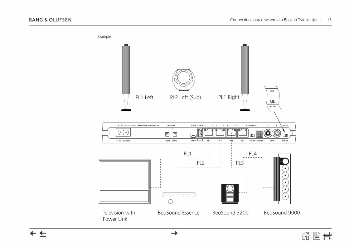
Example
100 - 240V 50/60Hz
Television with Power Link
BeoSound Essence BeoSound 3200 BeoSound 9000
PL2 Left (Sub)PL1 Left PL1 Right
PL1
PL2 PL3
PL4

Setting up and connecting BeoLab Transmitter 1 16
Setting up and connecting BeoLab Transmitter 1An interactive video on setting up connections to BeoLab Transmitter 1 is found on www.bang-olufsen.com/interactive-guide/
Setting up the BeoLab Transmitter 1
TV product as the source- Ensure the speakers are set to WIRELESS.- Ensure all speakers and the BeoLab Transmitter 1 are disconnected
from mains.- Connect the BeoLab Transmitter 1 to the source product (TV or audio
master) using appropriate Power Link cables, TOSLINK or RCA cables.- Cables in both BeoLab Transmitter 1 and Bang & Olufsen source
product must be in numerically increasing order; i.e. PL 1 to PL 1, Start with the PL 1 socket and fill in the PL sockets from left to right. Predefined Power Link sockets are likewise connected to the PL 1, PL 2 sockets etc. It is recommended to place cable with the subwoofer source signal in the rightmost Power Link socket of the sockets used. TOSLINK or RCA cables are connected to their matching connectors. Advice: Keep a record of cables and Power Link sockets.
- Set B&O INPUT switch to YES. When the source is not a Bang & Olufsen product the B&O INPUT switch must be set to NO. When set to YES the BeoLab Transmitter 1 reacts to the PL signal Speaker On/Off. When set to NO the BeoLab Transmitter 1 reacts to the signal level in the speaker channels (sound/noise).
- When source input comes to more Power Link sockets, the SUB 2.1 switch is set to OFF.
Audio product as the source (see next page)- Set the SUB 2.1 switch to ON when the input is a stereo signal and the bass
management function of the BeoLab Transmitter 1 is providing the signal to a wireless subwoofer in the third sound channel PL2 L.
- Connect mains to all speakers and the BeoLab Transmitter 1. The WIRELESS LED will start flashing white during the configuration process.
PL 5 PL 4MONITORCONTROL
PUC 2A+B
PUC 1A+B EXT. IR
PL 3 PL 2 PL1 PUC 3 A+BCTRL 3 CTRL 2 CTRL 1
BeoLab Transmitter 1 BeoVision 11
CTRL 1PUC2 A+B
CTRL 3PUC1 A+B
CTRL 2PL1 PL2 PL3
BeoLab Transmitter 1 BeoPlay V1
BeoLab Transmitter 1 BeoVision 10
POWER LINKCENTRE 1 1(SUB) 2 3 4 5 6
BeoLab Transmitter 1 BeoVision 7-40 MKIII to MKIV and TV
REAR FRONT
SUBWOOFER
REAR
SURROUND SOUND SPEAKERS
FRONT
CINEMACENTRE
BeoLab Transmitter 1
BeoVision 7-40 to MKII
Setting up and connecting BeoLab Transmitter 1 17
The Product Status LED on the front will be solid red, indicating it turns On and becomes ready for operation and turns Off after 10 s time-out.
- The Wireless indicator on the speaker starts flashing green, indicating it is not yet associated to the BeoLab Transmitter 1. When associated the LED stops flashing green. (In case the speaker behaves differently, please refer to the guide included with the speaker).
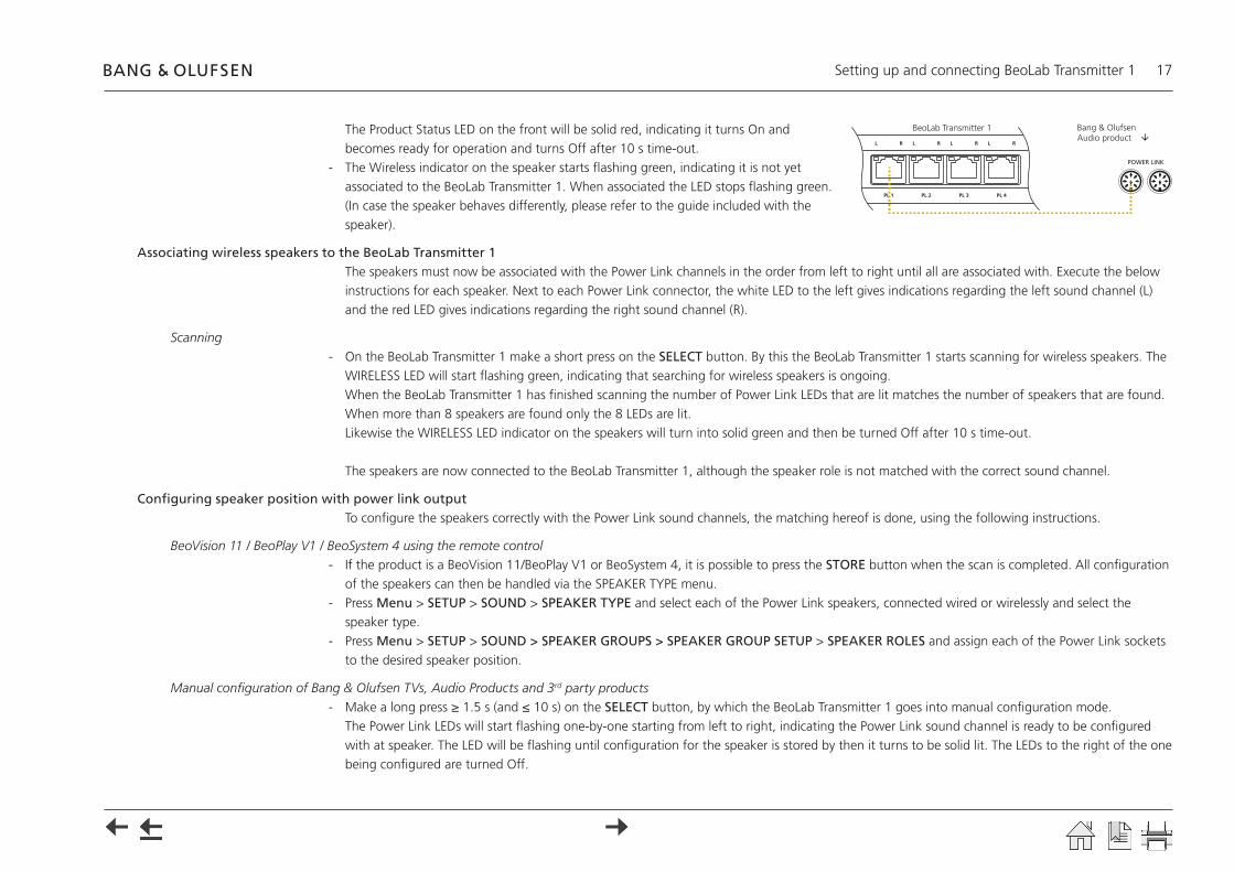
Associating wireless speakers to the BeoLab Transmitter 1The speakers must now be associated with the Power Link channels in the order from left to right until all are associated with. Execute the below instructions for each speaker. Next to each Power Link connector, the white LED to the left gives indications regarding the left sound channel (L) and the red LED gives indications regarding the right sound channel (R).
Scanning- On the BeoLab Transmitter 1 make a short press on the SELECT button. By this the BeoLab Transmitter 1 starts scanning for wireless speakers. The
WIRELESS LED will start flashing green, indicating that searching for wireless speakers is ongoing. When the BeoLab Transmitter 1 has finished scanning the number of Power Link LEDs that are lit matches the number of speakers that are found. When more than 8 speakers are found only the 8 LEDs are lit. Likewise the WIRELESS LED indicator on the speakers will turn into solid green and then be turned Off after 10 s time-out.
The speakers are now connected to the BeoLab Transmitter 1, although the speaker role is not matched with the correct sound channel.
Configuring speaker position with power link outputTo configure the speakers correctly with the Power Link sound channels, the matching hereof is done, using the following instructions.
BeoVision 11 / BeoPlay V1 / BeoSystem 4 using the remote control- If the product is a BeoVision 11/BeoPlay V1 or BeoSystem 4, it is possible to press the STORE button when the scan is completed. All configuration
of the speakers can then be handled via the SPEAKER TYPE menu.- Press Menu > SETUP > SOUND > SPEAKER TYPE and select each of the Power Link speakers, connected wired or wirelessly and select the
speaker type.- Press Menu > SETUP > SOUND > SPEAKER GROUPS > SPEAKER GROUP SETUP > SPEAKER ROLES and assign each of the Power Link sockets
to the desired speaker position.
Manual configuration of Bang & Olufsen TVs, Audio Products and 3rd party products- Make a long press ≥ 1.5 s (and ≤ 10 s) on the SELECT button, by which the BeoLab Transmitter 1 goes into manual configuration mode.
The Power Link LEDs will start flashing one-by-one starting from left to right, indicating the Power Link sound channel is ready to be configured with at speaker. The LED will be flashing until configuration for the speaker is stored by then it turns to be solid lit. The LEDs to the right of the one being configured are turned Off.
POWER LINK
BeoLab Transmitter 1 Bang & Olufsen Audio product

Setting up and connecting BeoLab Transmitter 1 18
(Power Link channels are dedicated according to the output from the source).- Noise is generated by the BeoLab Transmitter 1 and the noise is emitted from a (random) speaker that may not be the correct one matching the
Power Link (sound) channel indicated by the flashing LED. Make a short press ≤ 1.5 s on the SELECT button once or repeatedly until the noise is emitted from the speaker position desired.
- Make a short press ≤ 1.5 s on the STORE button, by which the Power Link (sound) channel and the speaker are matched and stored in the configuration table (speaker mapping table). The LED with that Power Link (sound) channel will stop flashing. If not all speakers are configured the LED of the next Power Link channel will start flashing. Now repeat the instruction step just above. Se also page 12 ff when more than 11 speakers are to be configured.
The below example illustrates the Power Link LED indications when speaker for the 3rd sound channel is being configured.
Speaker setup in TV menu
BeoVision 7-40- Press Menu > OPTIONS > SOUND > SPEAKER TYPES and move the cursor to the first line.
Sound will be emitted from one of the speakers. First line is predefined as CENTRE. Go to first line after SPEAKERS and the first two are predefined as subwoofers. Step through the list and for each speaker emitting a sound assign the speaker type of the speaker; e.g. BeoLab 17.
- Press Menu > OPTIONS > SOUND > SPEAKER ROLES and move the cursor through the list, one speaker at a time. A sound is heard from a speaker. Choose a speaker role that matches the position of the speaker.
BeoVision 10- Press Menu > OPTIONS > SOUND > SPEAKER TYPE and move the cursor to the first line.
Step through the list and for each speaker position assign the type of the speaker; e.g. BeoLab 17. Sound can now be emitted through each speaker. To optimise the sound experience, configure the levels and listening distances in the appropriate setup menus.

Push button functions 19
Push button functionsState SELECT STORE Time Comment
Scan X (short) - ≤1.5 s In non-configuration mode: Scans for wireless speakersIn configuration mode: Lit Power Link LEDs to show the number of speakers found
Store default - X (short) ≤1.5 s Scanning completed: store default. Note: when SUB 2.1 is set to On, manual configuration is forcedShow Power Link channel - X (long) ≥ 1.5 s and ≤10 s Show status on Power Link LEDs (turns Off after 10 s time-out)Manual configuration mode X (long) - ≥ 1.5 s and ≤10 s Configuration mode: Mode for manually configuring the match between the sound channel and a
speakerShift noise to next speaker X (short) - ≤1.5 s Configuration mode: Move emitted noise to another speakerFinish manual configuration * X (long) ≥ 1.5 s and ≤10 s Configuration mode: Finish manual configuration whenever desiredStore - X (short) ≤1.5 s Configuration mode: Stores the configuration of the match between the sound channel and a
speaker and continue with next channelStore * - X (long) ≥ 1.5 s and ≤10 s Configuration mode: Stores the configuration of the match between the sound channel and a
speaker and remain on same channel to be matched with another speakerBelow: Press buttons simultaneously!
Cancel X (short) X (short) ≤1.5 s Configuration mode: Move emitted noise one step back to previous sound channel to reconfigure an inadvertently stored configuration
Reset association X (long) X (long) ≥ 1.5 s and ≤10 s Erase speaker mapping. Bang & Olufsen speakers will then flash green. If not press (long) the RESET button on the speaker(s)
Factory reset X (very long) X (very long) ≥ 10 s Erase speaker mapping, and resets the settings to factory default Bang & Olufsen speakers will then flash green. If not press (long) the RESET button on the speaker(s)
* Functions available with the SW ver. 1.1 and newer.
Note: The cancel function me be used whenever a configuration of a speaker with at sound channel is to be regretted
If the product is a BeoVision 11/BeoPlay V1 or BeoSystem 4, it is possible to press the STORE button when the scan is completed. All configuration of the speakers can then be handled via the SPEAKER CONNECTIONS menu.
LED indications 20
LED indications
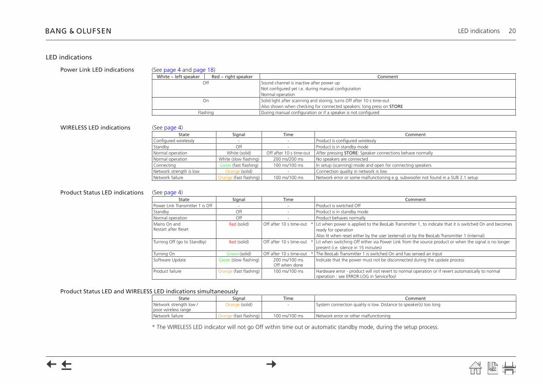
Power Link LED indicationsWhite ~ left speaker Red ~ right speaker Comment
Off Sound channel is inactive after power up Not configured yet i.e. during manual configurationNormal operation
On Solid light after scanning and storing; turns Off after 10 s time-out Also shown when checking for connected speakers: long press on STORE
Flashing During manual configuration or if a speaker is not configured
WIRELESS LED indicationsState Signal Time Comment
Configured wirelessly - - Product is configured wirelesslyStandby Off - Product is in standby modeNormal operation White (solid) Off after 10 s time-out After pressing STORE: Speaker connections behave normallyNormal operation White (slow flashing) 200 ms/200 ms No speakers are connectedConnecting Green (fast flashing) 100 ms/100 ms In setup (scanning) mode and open for connecting speakersNetwork strength is low Orange (solid) - Connection quality in network is lowNetwork failure Orange (fast flashing) 100 ms/100 ms Network error or some malfunctioning e.g. subwoofer not found in a SUB 2.1 setup
Product Status LED indicationsState Signal Time Comment
Power Link Transmitter 1 is Off - - Product is switched OffStandby Off - Product is in standby modeNormal operation Off - Product behaves normallyMains On and Restart after Reset
Red (solid) Off after 10 s time-out * Lit when power is applied to the BeoLab Transmitter 1, to indicate that it is switched On and becomes ready for operation Also lit when reset either by the user (external) or by the BeoLab Transmitter 1 (internal)
Turning Off (go to Standby) Red (solid) Off after 10 s time-out * Lit when switching Off either via Power Link from the source product or when the signal is no longer present (i.e. silence in 15 minutes)
Turning On Green (solid) Off after 10 s time-out * The BeoLab Transmitter 1 is switched On and has sensed an inputSoftware Update Green (slow flashing) 200 ms/100 ms
Off when doneIndicate that the power must not be disconnected during the update process
Product failure Orange (fast flashing) 100 ms/100 ms Hardware error - product will not revert to normal operation or if revert automatically to normal operation : see ERROR LOG in ServiceTool
Product Status LED and WIRELESS LED indications simultaneouslyState Signal Time Comment
Network strength low / poor wireless range
Orange (solid) - System connection quality is low. Distance to speaker(s) too long
Network failure Orange (fast flashing) 100 ms/100 ms Network error or other malfunctioning
* The WIRELESS LED indicator will not go Off within time out or automatic standby mode, during the setup process.
(See page 4 and page 18)
(See page 4)
(See page 4)

Use of ServiceTool - SW update - BeoLab Transmitter 1 21
Use of ServiceToolThe ServiceTool is used for SW update during installation - apart from that the ServiceTool is primarily used with service and repair situations. Follow the instructions with the mode and actions chosen.
SW update - BeoLab Transmitter 1Note: A standard USB A to USB Mini-B cable is used for connection between the PC hosting the ServiceTool and the BeoLab Transmitter 1 (Part No.: 6270848) and also a the CDC/ACM driver must be installed. (In ServiceTool, see Connections > USB Driver).In the Launch view (activate the LAUNCH PAD in the quick launch tray of the ServiceTool), activate the Connections tool, and under USB driver activate the Execute CDC/ACM driver installer. Usually the PC must be restarted for the driver to work.
- Connect the BeoLab Transmitter 1 to the mains.- Connect the USB Mini-B connector (Service) of the BeoLab Transmitter 1 to a USB A connector of the PC hosting the ServiceTool.- Identify the Com port used on the PC by entering e.g. Start > Control Panel > Hardware and Sound > Device Manager, and under
Ports (COM & LPT) it shows ATI COM port (COM n) where n is the number of the chosen Com port.- In the lower left corner of the ServiceTool, remember to select the Com port used to connect to the BeoLab Transmitter 1.- Select the BeoLab Transmitter 1 in the product list and open the entries Software > Automatic Software Update.
Follow the instructions in the ServiceTool, that are:- Press the Read button to see the present Software in the Product.- Under Select Software Build, and in the Version drop-down list select the desired SW build and press Update.
The Product Status LED will be slowly flashing green during the update process.In the Logging field, the progress of the SW update will be shown, ending by indicating the final status.
Use or USB memory stick - SW update 22
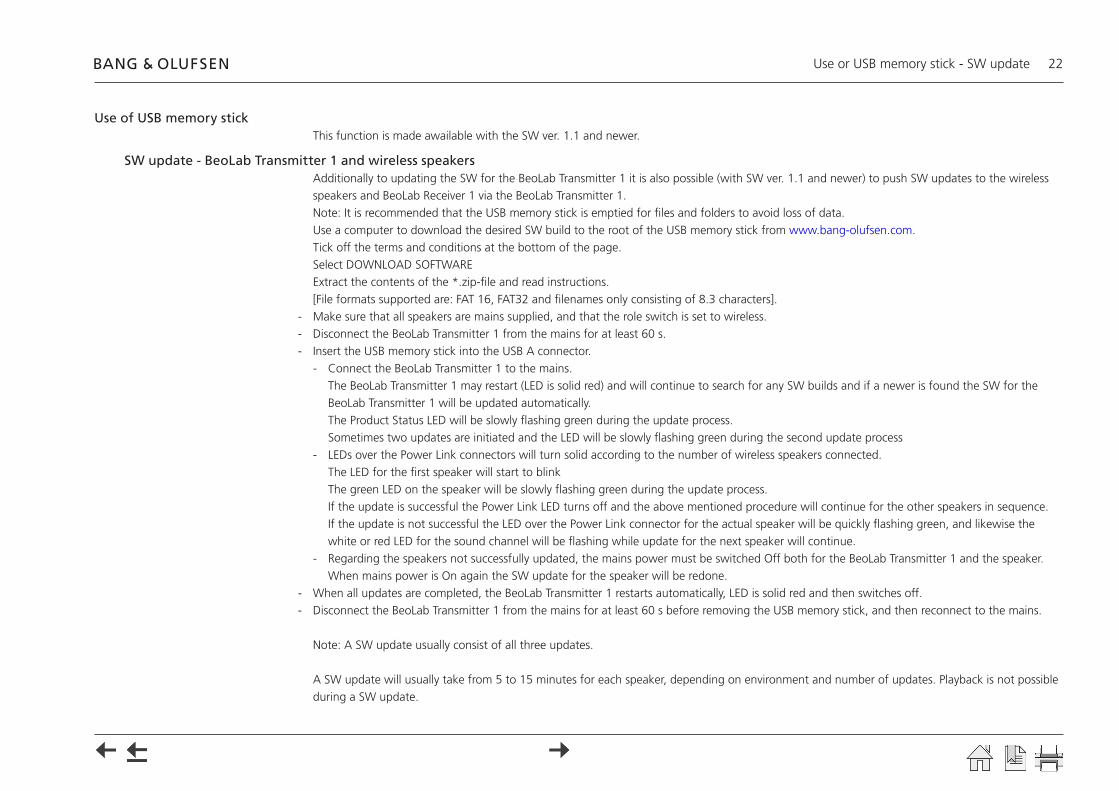
Use of USB memory stickThis function is made awailable with the SW ver. 1.1 and newer.
SW update - BeoLab Transmitter 1 and wireless speakers Additionally to updating the SW for the BeoLab Transmitter 1 it is also possible (with SW ver. 1.1 and newer) to push SW updates to the wireless speakers and BeoLab Receiver 1 via the BeoLab Transmitter 1.Note: It is recommended that the USB memory stick is emptied for files and folders to avoid loss of data.Use a computer to download the desired SW build to the root of the USB memory stick from www.bang-olufsen.com. Tick off the terms and conditions at the bottom of the page.Select DOWNLOAD SOFTWARE Extract the contents of the *.zip-file and read instructions. [File formats supported are: FAT 16, FAT32 and filenames only consisting of 8.3 characters].
- Make sure that all speakers are mains supplied, and that the role switch is set to wireless.- Disconnect the BeoLab Transmitter 1 from the mains for at least 60 s.- Insert the USB memory stick into the USB A connector.
- Connect the BeoLab Transmitter 1 to the mains. The BeoLab Transmitter 1 may restart (LED is solid red) and will continue to search for any SW builds and if a newer is found the SW for the BeoLab Transmitter 1 will be updated automatically. The Product Status LED will be slowly flashing green during the update process. Sometimes two updates are initiated and the LED will be slowly flashing green during the second update process
- LEDs over the Power Link connectors will turn solid according to the number of wireless speakers connected. The LED for the first speaker will start to blink The green LED on the speaker will be slowly flashing green during the update process. If the update is successful the Power Link LED turns off and the above mentioned procedure will continue for the other speakers in sequence. If the update is not successful the LED over the Power Link connector for the actual speaker will be quickly flashing green, and likewise the white or red LED for the sound channel will be flashing while update for the next speaker will continue.
- Regarding the speakers not successfully updated, the mains power must be switched Off both for the BeoLab Transmitter 1 and the speaker. When mains power is On again the SW update for the speaker will be redone.
- When all updates are completed, the BeoLab Transmitter 1 restarts automatically, LED is solid red and then switches off.- Disconnect the BeoLab Transmitter 1 from the mains for at least 60 s before removing the USB memory stick, and then reconnect to the mains.
Note: A SW update usually consist of all three updates.
A SW update will usually take from 5 to 15 minutes for each speaker, depending on environment and number of updates. Playback is not possible during a SW update.
Use or USB memory stick - SW update 23
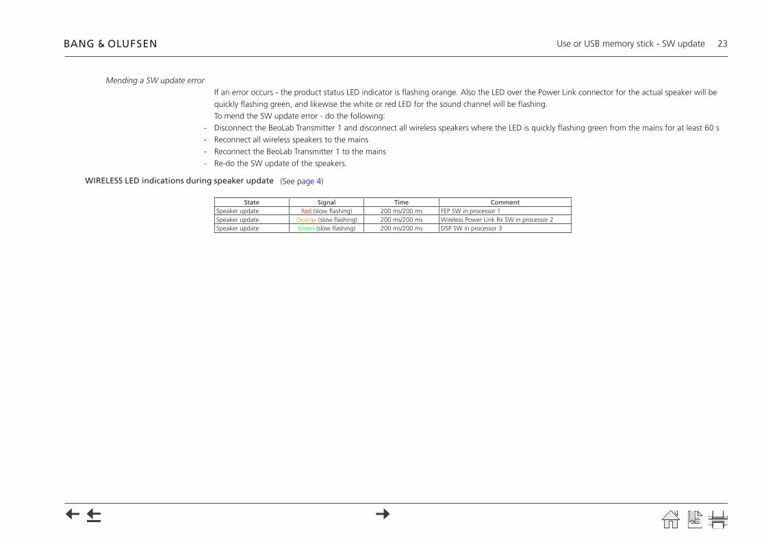
Mending a SW update errorIf an error occurs - the product status LED indicator is flashing orange. Also the LED over the Power Link connector for the actual speaker will be quickly flashing green, and likewise the white or red LED for the sound channel will be flashing.To mend the SW update error - do the following:
- Disconnect the BeoLab Transmitter 1 and disconnect all wireless speakers where the LED is quickly flashing green from the mains for at least 60 s- Reconnect all wireless speakers to the mains- Reconnect the BeoLab Transmitter 1 to the mains- Re-do the SW update of the speakers.
WIRELESS LED indications during speaker update
State Signal Time CommentSpeaker update Red (slow flashing) 200 ms/200 ms FEP SW in processor 1Speaker update Orange (slow flashing) 200 ms/200 ms Wireless Power Link Rx SW in processor 2Speaker update Green (slow flashing) 200 ms/200 ms DSP SW in processor 3
(See page 4)
IR-eye - 3rd party product remote control 24
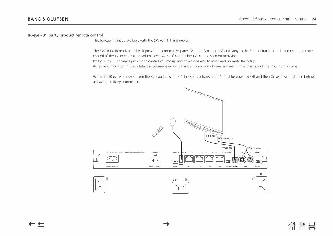
IR-eye - 3rd party product remote controlThis function is made available with the SW ver. 1.1 and newer.
The RVC3000 IR receiver makes it possible to connect 3rd party TVs from Samsung, LG and Sony to the BeoLab Transmitter 1, and use the remote control of the TV to control the volume level. A list of compatible TVs can be seen on BeoWise.By the IR-eye it becomes possible to control volume up and down and also to mute and un-mute the setup.When returning from muted state, the volume level will be as before muting - however never higher than 2/3 of the maximum volume.
When the IR-eye is removed from the BeoLab Transmitter 1 the BeoLab Transmitter 1 must be powered Off and then On as it will first then behave as having no IR-eye connected.
100 - 240V 50/60Hz
L R
SUB
TOSLINKRCA Line-out
RCA Line-inTOSLINK
Always On 25
Always OnThis function is made available with the SW ver. 1.1 and newer.
The BeoLab Transmitter 1 and wireless speakers are per default set to enter a standby state a while after not being actively used. When being powered on again there is a delay before sound is heard from the speakers.
If desired it is possible to set the BeoLab Transmitter 1 to “Always On” by which the delay is reduced to about 2 s when it is desired to hear sound from the speakers almost instantly.
Always On can be set to true or false as described in the section about Line-in setting and log files, see page 26.A USB memory stick is needed having a file in the root with the name: WPLSETUP.TXT and this file shall contain the command line text: ALWAYS ON:TRUE
- Disconnect the BeoLab Transmitter 1 from mains for at least 60 s.- Insert the USB memory stick into the USB A socket- Reconnect the BeoLab Transmitter 1 to mains
The BeoLab Transmitter 1 restarts indicated by the product status LED being solid red The USB memory stick must remain in the BeoLab Transmitter 1 for 10 s before being removed again.
- Disconnect the BeoLab Transmitter 1 from mains for at least 60 s.- Remove the USB memory stick- Reconnect the BeoLab Transmitter 1 to mains
Note: It is recommended not to set ALWAYS ON:TRUE in countries having 5 or fewer 5 GHz channels; see page 27.
Line-in setting and log files 26
Line-in setting and log files
Via USB memory stickThe line-in settings can be changed on BeoLab Transmitter 1 by the content of a file called WPLSETUP.TXT placed on a USB memory stick. At the same time log files can be dumped to the USB memory stick.[File formats supported are: FAT 16, FAT32 and filenames only consisting of 8.3 characters].The WPLSETUP.TXT file and the format for the settings can be obtained as follows:
- Insert an empty USB memory stick into the USB A connector. The BeoLab Transmitter 1 will then create a file on the USB memory stick with the file name WPL_DUMP.TXT.
- Move the USB memory stick to a PC and using a simple text editor, the setting values can be changed according to the source product used with the BeoLab Transmitter 1; see table below.
- Change the filename to WPLSETUP.TXT. All lines starting with ‘;’ (semicolon) are regarded as comment lines.
- Disconnect the BeoLab Transmitter 1 from the mains for at least 60 s.- Insert the USB memory stick into the USB A connector. (Must remain in the USB A socket for at least 60 s to ensure all logging dumped after
restart).- Connect the BeoLab Transmitter 1 to the mains. Restart is indicated by the product status LED being solid red- The BeoLab Transmitter 1 discovers the WPLSETUP.TXT file, and the settings for line-in are set in the BeoLab Transmitter 1.
A file named WPL_DUMP.TXT will be created on the USB memory stick; or alternatively overwrite the existing file of the same name. If a line with the text: ERROR QUEUE PLEASE is found in the WPLSETUP.TXT file, the error log will be dumped in a file named WPLERROR.TXT when the USB memory stick is inserted into the USB A connector.
If a line with the text: STORE DFS LOG is found in the WPLSETUP.TXT file, a log file consisting of 1000 entries (in a circle buffer) separated by semicolon is dumped to the USB memory stick. Entries are changes in the setup of the BeoLab Transmitter 1.
All the above files are or must be located in the root folder of the USB memory stick.
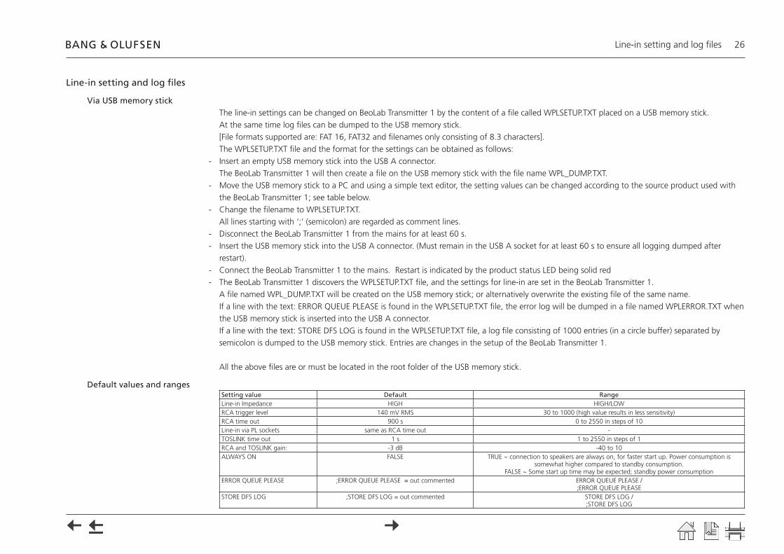
Default values and rangesSetting value Default RangeLine-in Impedance HIGH HIGH/LOWRCA trigger level 140 mV RMS 30 to 1000 (high value results in less sensitivity)RCA time out 900 s 0 to 2550 in steps of 10Line-in via PL sockets same as RCA time out -TOSLINK time out 1 s 1 to 2550 in steps of 1RCA and TOSLINK gain: -3 dB -40 to 10ALWAYS ON FALSE TRUE ~ connection to speakers are always on, for faster start up. Power consumption is
somewhat higher compared to standby consumption. FALSE ~ Some start up time may be expected; standby power consumption
ERROR QUEUE PLEASE ;ERROR QUEUE PLEASE = out commented ERROR QUEUE PLEASE / ;ERROR QUEUE PLEASE
STORE DFS LOG ;STORE DFS LOG = out commented STORE DFS LOG / ;STORE DFS LOG

Combination of Channel pattern and product type No. 27
Combination of Channel pattern and product type No.The below table show combinations of 5 GHz channels used in the BeoLab Transmitter 1 with respect to countries.
Channel pattern
Product type No.
Countries Channel number
36
40
44
48
52
56
60
64
100
104
108
112
116
120
124
128
132
136
140
149
153
157
161
165
HF1 1505 Argentina, Brazil, Peru, Philippines, United Arab Emirates, Uruguay, Vietnam
1506 Canada, Dominican Republic, Mexico, USA, Virgin Islands
1507 Hong Kong, Namibia, South Africa
1508 Australia, New Zealand
1512 Thailand
HF2 1505 Andorra, Austria , Belgium, Bulgaria, Croatia, Czech Republic, Denmark, Estonia, Faroe Islands, Finland, France, Georgia, Germany, Ghana, Greece, Greenland, Holland, Hungary, Iceland, Italy, Latvia, Lebanon, Liechtenstein, Lithuania, Luxembourg, Monaco, Norway, Oman, Poland, Portugal, Romania, Saudi Arabia, Serbia, Slovak Republic, Slovenia, Spain, Sweden, Switzerland, Turkey
1507 Botswana, Ghana, Ireland, UK
HF3 1505 Bahrain, Chile, Egypt, India, Malaysia
1506 Panama
1507 Singapore
1511 Korea
HF4 1505 Azerbaijan, Israel, Kazakhstan, Morocco, Russia, Ukraine, Uzbekistan
1507 Kuwait
HF5 1505 Côte d’Ivoire, Indonesia, Nigeria, Pakistan, Qatar
1510 China
HF6 1509 Japan
HF7 1513 Taiwan
HF8 1505 Jordan
Legend:5 GHz channels
5 GHz channels with radar detection (DFS)
5 GHz channels not used by Bang & Olufsen BeoLab Transmitter 1
Due to national regulations channels and channel patterns can not be chosen manually. The transmitter is certified to use only specific channels in each country.The automatic channel selection mechanism may in certain cases take more than 1 minute before a channel is allocated for sound transmission.Note: It is recommended not to set ALWAYS ON:TRUE in countries having 5 or fewer 5 GHz channels; see page 25.
Distance between 5 GHz transmitters 28
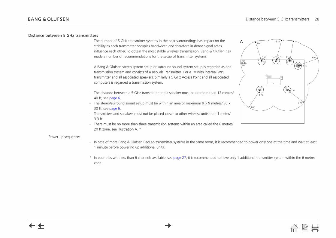
Distance between 5 GHz transmittersThe number of 5 GHz transmitter systems in the near surroundings has impact on the stability as each transmitter occupies bandwidth and therefore in dense signal areas influence each other. To obtain the most stable wireless transmission, Bang & Olufsen has made a number of recommendations for the setup of transmitter systems.
A Bang & Olufsen stereo system setup or surround sound system setup is regarded as one transmission system and consists of a BeoLab Transmitter 1 or a TV with internal WPL transmitter and all associated speakers. Similarly a 5 GHz Access Point and all associated computers is regarded a transmission system.
- The distance between a 5 GHz transmitter and a speaker must be no more than 12 metres/ 40 ft; see page 6.
- The stereo/surround sound setup must be within an area of maximum 9 × 9 metres/ 30 × 30 ft; see page 6.
- Transmitters and speakers must not be placed closer to other wireless units than 1 meter/ 3.3 ft.
- There must be no more than three transmission systems within an area called the 6 metres/ 20 ft zone, see illustration A. *
Power-up sequence:- In case of more Bang & Olufsen BeoLab transmitter systems in the same room, it is recommended to power only one at the time and wait at least
1 minute before powering up additional units.
* In countries with less than 6 channels available, see page 27, it is recommended to have only 1 additional transmitter system within the 6 metres zone.
A
1 m
1 m
6 m
6 m
6 m
6 m6 m
1 m
1 m
1 m
1 m
1 m

Site survey (Wi-Spy) 29
Site survey (Wi-Spy)Usually wireless speaker connections should not lead to problems. The BeoLab Transmitter 1 is able to find unused channels in the 5 GHz band, and makes a map of unused channels in case the present channel in use becomes occupied by another transmission system. In such case moving to an alternative channel happens seamlessly.Despite this it is recommended to make a site survey in dense residential areas as well as enterprise areas, in countries with few channels (see page 27), in areas known for wireless problems and if many 5 GHz transmission systems nearby.In a repair situation a site survey can also reveal if problems are related to lack of channels in the 5 GHz transmission system. The Wi-Spy DBx + Chanalyzer Pro can be used to visualize which 5 GHz channels are used and unused.
Note: The free-ware program inSIDDer can show all channels, and identify WLAN traffic, whereas it is not able to see radio traffic from other transmission systems using the 5 GHz band (see page 27).
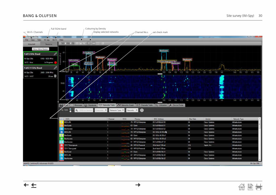
Setting up Wi-SpyFrom the Wi-Spy toolbar do the following (see example of Wi-Spy recording on the next page):
- Press View and select Wi-Fi Channels.- Press Wi-Spy and select Full 5 GHz Band; to scan in the 5 GHz band.- Press Wi-Fi and select the net board of your computer; in this example Intel(R) Centrino(R) Advanced-N 6205; to enable the on-board WLAN.- Click on the tool to have the Display selected networks (WLANs) enabled; by this the WLAN can be seen in the recordings.- Click on the tool to have Colouring by Density enabled.- Set at check mark (√) next to SSID, in the lower half of the display.
The total view will be as shown on the next page.
A recording is saved in the following way:- Press File > Save, and remember to record where, when and how the recordings were made. - State known wireless problems in the area, if any!
Observations for decision on wired/wirelessMake a Wi-Spy recording in the area where Wireless Power Link (WPL) is intended to be installed. Save the recording.Compare the channel pattern for the country with the recording.The possibilities for utilizing WPL are of course best when there are unused (free) channels.If the recording seems to indicate that most/all channels are used, it might still be possible to utilize WPL, if the signal strength in some channels are below - 80 dBm. The channels can not be manually selected for the BeoLab Transmitter 1.Make a wireless test setup, and in case it behaves stable, make the installation permanent. In case the test setup is unstable, or in case there are no unused channels, a wired solution is then the solution to a sound experience!
Site survey (Wi-Spy) 30
Channel No.sDisplay selected networksColouring by Density
Wi-Fi- ChannelsFull 5GHz band
set check mark
Connection specifications 31
Connection specifications
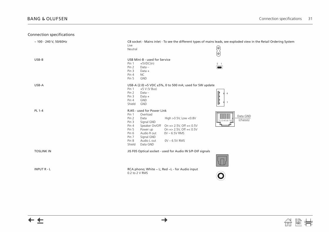
~ 100 - 240 V, 50/60Hz C8 socket - Mains inlet - To see the different types of mains leads, see exploded view in the Retail Ordering System LiveNeutral
USB-B USB Mini-B - used for ServicePin 1 +5VDC(in)Pin 2 Data –Pin 3 Data +Pin 4 NCPin 5 GND
USB-A USB-A (2.0) +5 VDC ±5%, 0 to 500 mA; used for SW updatePin 1 +5 V (V Bus)Pin 2 Data –Pin 3 Data +Pin 4 GNDShield GND
PL 1-4 RJ45 - used for Power LinkPin 1 OverloadPin 2 Data High >3.5V, Low <0.8VPin 3 Signal GNDPin 4 Speaker On/Off On => 2.5V, Off =< 0.5VPin 5 Power up On => 2.5V, Off =< 0.5VPin 6 Audio R out 0V – 6.5V RMSPin 7 Signal GNDPin 8 Audio L out 0V – 6.5V RMSShield Data GND
TOSLINK IN JIS F05 Optical socket - used for Audio IN S/P-DIF signals
INPUT R - L RCA phono; White ~ L; Red ~L - for Audio input0.2 to 2 V RMS
5 1
4
1
1 2 3 4 5 6 7 8
Data GND(chassis)
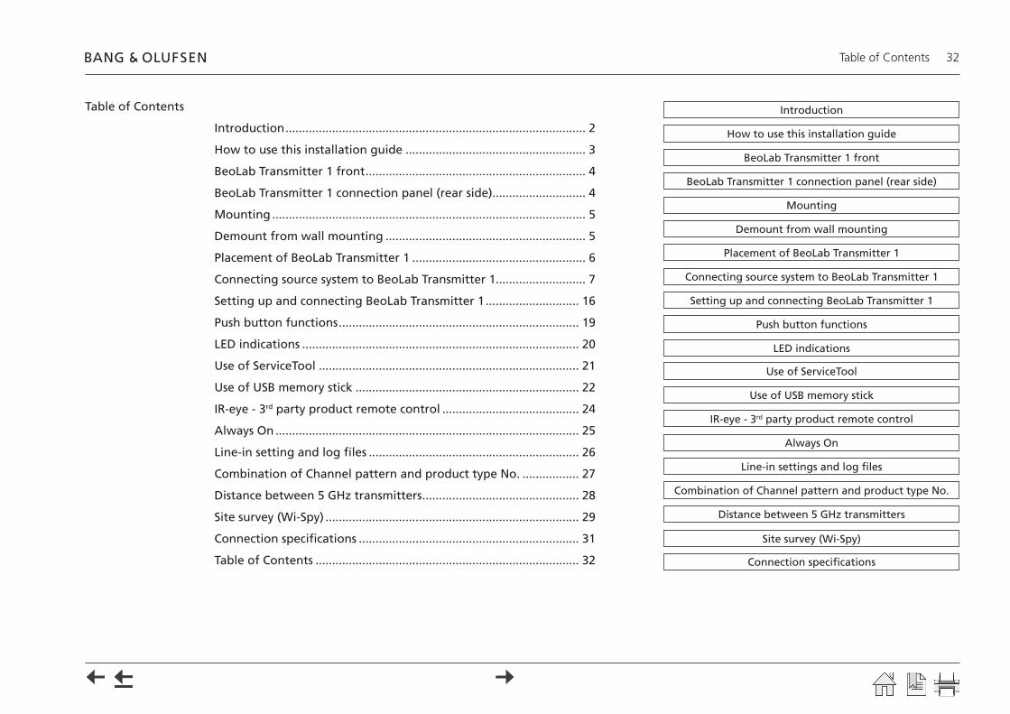
Table of Contents 32
Introduction
Connecting source system to BeoLab Transmitter 1
Placement of BeoLab Transmitter 1
LED indications
Site survey (Wi-Spy)
Use of USB memory stick
IR-eye - 3rd party product remote control
Always On
Line-in settings and log files
Use of ServiceTool
How to use this installation guide
Setting up and connecting BeoLab Transmitter 1
Push button functions
Combination of Channel pattern and product type No.
Distance between 5 GHz transmitters
Connection specifications
BeoLab Transmitter 1 front
BeoLab Transmitter 1 connection panel (rear side)
Demount from wall mounting
Mounting
Table of Contents
Version 1.1 - 2014-06
Table of Contents
Introduction .......................................................................................... 2
How to use this installation guide ...................................................... 3
BeoLab Transmitter 1 front .................................................................. 4
BeoLab Transmitter 1 connection panel (rear side)............................ 4
Mounting .............................................................................................. 5
Demount from wall mounting ............................................................ 5
Placement of BeoLab Transmitter 1 .................................................... 6
Connecting source system to BeoLab Transmitter 1........................... 7
Setting up and connecting BeoLab Transmitter 1 ............................ 16
Push button functions ........................................................................ 19
LED indications ................................................................................... 20
Use of ServiceTool .............................................................................. 21
Use of USB memory stick ................................................................... 22
IR-eye - 3rd party product remote control ......................................... 24
Always On ........................................................................................... 25
Line-in setting and log files ............................................................... 26
Combination of Channel pattern and product type No. ................. 27
Distance between 5 GHz transmitters ............................................... 28
Site survey (Wi-Spy) ............................................................................ 29
Connection specifications .................................................................. 31
Table of Contents ............................................................................... 32


