124
Best, Avai~lable Copy

Best,Avai~lable
Copy

BestAvailable
Copy

AD-A281 047 C9
DTICFINAL REPORTL% BELECTE
jUN 3 19v F D-
Grant Title: Growth, Characterization and Applications of J3-BariumBorate and Related Crystals
Grant Number: N00014-90-J-4107
Period of Performance: August 1, 1990 - October 31, 1993
Dollar Amount: $ 295,000
Scientific Officer: John McMahonNaval Research LaboratoryOptical Sciences Division I)"ze QV,4555 Overlook AvenueWashington, DC 20375
Principal Investigator: C. L. Tang.<.%
Institution: Comell University (Ithaca, NY 14853
This doc -nt hcu be... QPProIdior public release and sale; its
distnibutioa is uiimieod.-
94-18711IIIIIIIUUUIUII1 •B -i 5 r• "II
Final Report to NRL onGrowth, Characterization, and Applications of
13-Barium Borate and Related Crystals(1990 to 1993)
Submitted by
C. L. Tang
Cornell University, Ithaca, NY 14853
Emphasis of our program during the past three years has been on improving thesize and quality of 0-barium borate (BBO) crystal; developing the growth recipe for lithium
triborate crystal (LBO); automation of the growth process of BBO and LBO;
characterization of LBO; developing optical parametric oscillators using BBO, LBO, andnew nonlinear crystals such as KTiOPO4 (KTP), KTA (arsenate), C(Cs)TA, and
R(Rb)TA; and finally helping to establish commercial sources of BBO and LBO crystals
and optical parametric oscillators making use of these new crystals. Significant progress
has been made in all these areas. The results are summarized below and in the Appendices
attached.
L Crystal Growth
Our initial efforts were on improving the size and quality of high temperature
solution grown BBO crystals and developing the growth recipe of LBO. These efforts
were highly successful [See Appendices A - C] and the technology developed in our
laboratory was licensed and transferred to Cleveland Crystals Inc. This company is now a
major supplier of BBO single crystals in this country. The availability of such U. S.
grown crystals was instrumental in convincing major laser companies such as Spectra
Physics and Coherent to develop laser related equipment that makes use of BBO crystals.
Our program has played a leading role h-. the recent rapid development of OPO technology
in both the nanosecond and the femtosecond time domains. [See, for example, attachment
in Appendix D].
Since Cleveland Crystals has now become an established American commercial
source of BBO based on our licensed technology, we felt that it was a good time for us to
try something new. The critical need was to automate the growth process to get away from
manual control based upon visual monitoring and the experiences and judgment of the
grower. With visual monitoring and human control, there was no hope of significantly ,:esi or
2

improving the quality, yield, and growth speed. Real advances in the BBO crystal growth
technology cannot happen without automation of the growth process.
For these reasons, we decided to take a chance and devote all our efforts and
resources to converting our growth setups to that with computer-controlled and electronic-
weighing. This hardware and software development part of the program is now finallycompleted. We have started our first growth runs. We still have to perfect our growthrecipe based on past accumulated experiences and develop it into a computerized recipe.After which, we should get precisely repeatable results with each run and make systematic
improvements on quality, yield, and size of the crystals. Without precisely reproducible
results, there is no hope for anyone to make systematic improvements effectively.The initial results from the automated growth setup look very good. We can see
minute changes in the growth furnace due to small perturbations in the lab environment.
Details of both the computer controlled setups and the initial results were discussed in the
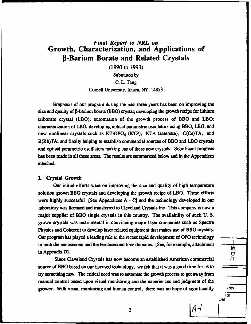
progress report we submitted to NRL on March 31, 1993. The latest version of the
growth setup which allows the seed to be separately cooled and has new seed mounting
scheme is shown schematically in the anatched figure at the end of the text of this report.
II. Characterization of LBO
In addition to the growth of single crystals, it is also important that the crystals are
thoroughly characterized. This is especially true for LBO where there is considerable
controversy even on such an important parameter as the noncritical phase-matchingtemperature at 1.06 gIm. A detailed LBO characterization program was initiated in our
laboratory. The characteristic properties of noncritically phase-matched second-harmonic
generation in LBO were investigated. Using an LBO crystal grown in our laboratory, we
deomonstrated temperature-tuned noncritical phase-matched second-harmonic generationfrom 1.025 to 1.253 gim in the temperature range from 190 to -30 C. The noncritical
phase-matching temperature for 1.064 gtm radiation is found to be 148+/-0.50 C with a
temperature acceptance bandwidth of 3.90 C-cm. Spectrum-tuned noncritical phase
matching at room temperature has been achieved at 1.215 mm. Angle-tuned critically
phase-matched second-harmonic generation of near-infrared radiation has also been
achieved. Large angular, temperature, and spectral acceptance bandwidths were obtained.
The these results have all been published [Appendices C and El.
HL Applications of BBO and Related Crystals
A substantial part of our efforts has also been devoted to developing the
applications of BBO, LBO and other new nonlinear optical crystals, notably the KTP(KTiOPO4)-isomorphs such KTP, KTA, CTA, and RTA. A series of patents covering
many aspects of the OPO technology have begi generated and licensed to industry. The

BBO nanosecond OPO technology [See review article in Appendix F] licensed and
transferred from our laboratory to Spectra Physics[Appendix D] is now a successfulcommercial venture with over a hundred OPO systems sold within the first year it was
introduced. The femtosecond OPO technology pioneered in our program [Appendix G]
and transferred to industry is also now being pursued by several major companies
including Spectra Physics and Coherent. License agreements with these companies are
under discussion.
Other new applications of BBO that we have developed include the first
demonstrations of shifting the output of the recently dcveloped Ti:sapphire mode-locked
laser to the blue [Appendix H] and the output of the fs KTP OPO [Appednix I] invented in
our laboratory to the visible [Appendix J1. We have further demonstrated femntosecond
OPO operation in the new crystals such KTiOAsO4 [Appendix K], CsTiOAsO4
[Appendix LI, and RbTiOPO4 [Appenix MI for the first time. These OPO's extend the
operating range of broadly tunable high repetition rate ultrafast sources into the important
spectral range of 3 to 5 pim.
Finally, we have developed a thermal lens spectrometer using a computerized BBOOPO that is capable of continuous tuning from approximately 420 nm to 2 Am for
spectroscopic and spectrometric applications. This system allows any selected wavelength
within the tuning range to be reached directly and quickly. We demonstrated the versatility
of the system by measuring the entire visible (450 to 690 nrn) thermal lens spectrum of
NO2 with a computer-controlled automated continuous scan.
In summary, we have very susccessfully developed the growth process of
BBO and LBO crystals, characterized these materials, and developed extensive
applications of BBO and related crystals. A substantial part of the technologies developed
have already been transferred and licensed to industry.
4

I -Cool Wj ter In-eCool W teir Out
000 igAir Out -Coolif Air [
S,!,
Magnetic Coupling D.C. Motor
SAlumina Outer Rod
Schematic ofmodified pulling rod.
v"Platinum Seed Mount
Z •-Seed Crystal

Appendix A
AO�lg O�rwol �G,.I•D ae l C i.U. Vol. 20. Mp. 54? 01316- 5.00 + .60Pdw Ginan UaIn. Al rlghw mmv 0 1160 Prga,,mm Pvg pl
GROW-H AND CHARACTERIZATION OFNONLINEAR OPTICAL CRYSTALS SUITABLE FOR
FREQUENCY CONVERSIONL K. Chong, W. R. Bosenberg and C. L Tang
Materials Science Center, Comell University, Ithaca. New York 14853. U.S.A.
Abstract: During the past decade, important advances have been made in the development ofnonlinear optical materials suitable for frequency conversion. Better understanding of themicroscopic origins of optical nonlinearities has provided qualitative guidelines for the systematicsearch and synthesis of many new materials, organic and inorganic, which are particularlypromising for the construction of practical devices. Significant progress in the crystal growthtechnology has allowed the development of many excellent crystals that were once plagued bygrowth difficulties. We review here some of these advances, placing special emphasis on the hightemprasture solution growth of nonlinear optical crystals. In particular, we discuss in somewhatmore detail the growth and characterization of the newly discovered crystal, barium metaborate
WpBAB 2O4)-
Introduction :-
Since the discovery of second harmonic generation by Franken et. aL in 19611, nonlinearoptical mixing has been widely recognized as an effective method for the generation of highpower coherent radiation in spectral regions where efficient laser sources are unavailable.Devices based on nonlinear optical interactions promise to be efficient, compact, easy tooperate, and capable of operating in a wide spectral range. With a single fixed frequency laser,a combination of harmonic generation and optical parametric oscillation can provide fullytunable radiation throughout the UV and the IR2 -3 . The widespread use of these devices hasbeen limited by the lack of materials with suitable characteristics. Substantial progress hasbeen made in the development of nonlinear optical materials recently. Novel materals havingattraive properties are being discovered at a rapid pace4"8 , with advances in crystal growthtechnology making possible the commercial development of promising matrials such as urea,

10 L K. Cheng et al.
magnesium-oxide doped lithium niobate (MgO:LiNbO 3 ), potassium niobate (KNbO3),
potassium titanyl phosphate (KTP), and barium metaborate (0-BaB 20 4 ). Preliminary
experiments performed on these materials have been very encouraging 9 "1 0 and willundoubtedly lead to an increased use of these crystals in device applications.
In this paper, we shall examine some of these advances. An enormous body of work hasbeen published concerning the development of nonlinear crystals. It is, therefore, necessary tolimit the scope of this paper to a few specialized areas. In what follows, we shall be concernedwith bulk materials only. The growth and applications of crystal fibersI 1, and materials withmodulated structures 12- 13 , though important, will not be discussed. Likewise, we shall not
concern ourselves with organic materials. A comprehensive review of organic materials can befound in Chemla and Zyss 14 . In the growth of nonlinear optical cystals, we shall single outthe high temperature solution growth technique for discussion. This does not imply that othertechniques, such as Czochralski 15, Bridgeman-Stockbarger16, 17 and low temperature solutiongrowth 18 , are not important in the development of nonlinear optical crystals.
Characterization of nonlinear optical crystals can be divided into two types: themeasurement of optical properties and the investigation of growth defects. The former includes
the measurements of intrinsic physical properties which are directly relevant to opticalfrequency conversion. The latter includes the study of growth defects, such as twinning,phase homogeneity, mechanical stresses, inclusions...etc, that are the result of poor control ofcrystal growth parameters. Standard techniques such as trace chemical analysis, etching anddecoration, x-ray topography, elecron microprobe analysis...etc. can be used for defectcharacterization. The use of these techniques for crystal characterization has been reviewed byLaudise19 . We shall be primarily concerned with the characterization of the optical and other
relevant physical properties of nonlinear crystals.
This paper is organized in the following way. In section I, we discuss the basiccharacterization of nonlinear crystals. A set of material parameters is chosen which are usefulfor the comparison of different materials. The relative importance of these parameters and therelationships among them are discussed. A summary of several promising materials that aresuitable for applications in the UV-visible-near-IR range is presented for reference and to aiddiscussion. In section II, we review several aspects of the high temperature solution growth(HTSG) technique. Particular emphasis will be placed on the top-seeded method. In section1II, we discuss, as an example, the growth and characterization of the newly discovered
crystal, barium metaborate. In section IV, we conclude this paper by a survey of some of the
more important advances in the development of nonlinear optical materials.
CORNELLU N I V E R S I T Y
Office of Sponsored Programs 120 Day Flail Telephone W07/255-5014Ithaca, NY 14853-2801 Facsimile No. W07/255-5058
FIRST CLASS U.S. MAIl
June 6. 1994
Scientific Officer Code: 12621Guy W. BeaghlerOffice of Naval Research800 North Quincy StreetArlington. VA 22217-5000
SUBJECT: Final Technical Report for (rant Number N000l14-90-.1-4107
Dear Mr. Beaghler:
Enclosed are three copies of the subject report. This project. entitlcd "G(rowth,Characterization and Applications of P -Bariumn Borate and Related Crystals,"was under the direction of Professor C. L,. Tang in (he School of Electrical Engineering.
Sincerel y
Eric W. D)anlyAssistant Director
1)JC/hry
Enclosures
( C. L. Tang
X Administrative 6rants (lfficer (I copies)Office of Naval ResearchResident Representative N62927Administrative Contracting Officer33 Third Avenue - Lower LevelNew York. NY 10003-9988
Director (I Copy)Naval Research LaboratoryAttn: Code 2627Washington. DC 20375
Defense Technical Information Center (1 copy)Building 5, Cameron StationAlexandria, VA 22314
Please refer to OSP #19988 on all future correspondence.

Nonlinear optical crystals for frequency conversion 11
I. Material Considerations:-
Hundreds of materials have been identified as possessing optical nonlinearitiesl. To date.only a handful of these materials are routinely used in the generation of coherent radiation.This reflects the many criteria which a nonlinear crystal must satisfy before it can be used inpractical applications. The success of the "molecular engineering" approach 2 has led to a betterunderstanding of the relationship between the crystal structure and its optical nonlinearities andmade possible systematic search for new nonlinear materials. It is, therefore, appropriate toexamine, in an organized way, the desirable characteristics of nonlinear crystals that aresuitable for various applications. Qualitative discussion of this topic has been given in a recentreview3 . The following discussion will follow closely the approach taken there.
Traditionally, the usefulness of a nonlinear crystal has been evaluated in terms of thematerial parameters that are directly related to optical fiequency conversion. These included theoptical nonlinearities, optical damage threshold, birefringence, dispersion, transparency andoptical homogeneity. Little emphasis have been placed on the other characteristics such ascrystal growth properties, mechanical strength, thermal stress resistance and crystal fabricationproperties such as coating and polishing. Recent experiments in the practical application ofnonlinear materials4'5 have made it clear that more emphasis should be placed on these other
Properties.
The characterization of a nonlinear optical material includes the quantitative and qualitativespecification of these parameters. A general set of parameters is given below. The underlyingphysical principles for the selections of these parameters are discussed in standardreferences 6,7:
dýg2/n 3 is the nonlinear figure-of-merit [(pm/V)21.The nonlinear coefficient d is defined
by the expression P=2 0odE 2, where P is the nonlinear polarization and E is theelectric field.
rmnx is the single shot optical damage threshold. It is usually given as an intensity[GW/cm2] or an energy fluence [J/cm2]. For certain materials (e.g. urea) which havea cumulative damage property that depends on the duration of irradiation5 , this is nota useful characterization. For CW operation, a corresponding CW damage thresholdcan be defined.
nx(;), ny(.) and nzO.) are the refractive indices along the principal dielectric axes. Foruniaxial crystals, nX = ny. They defined the material dispersion and the birefringenceof a material. In a phase-matched nonlinear optical process in a crystal, the
12 L K. Cheng at l.
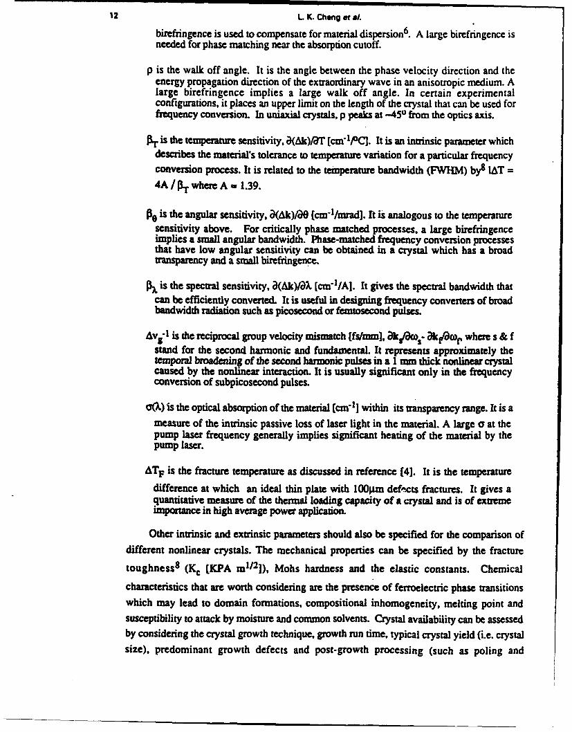
birefringence is used to compensate for material dispersion6. A large birefringence isneeded for phase matching near the absorption cutoff.
p is the walk off angle. It is the angle between the phase velocity direction and theenergy propagation direction of the extraordinary wave in an anisotropic medium. Alarge birefringence implies a large walk off angle. In certain experimentalconfigurations, it places an upper limit on the length of the crystal that can be used forfrequency conversion. In uniaxial crystals, p peaks at -451 from the optics axis.
Sis the temperature sensitivity, )(Ak)/'T [cm7'1]. It is an intrinsic parameter whichdescribes the material's tolerance to temperature variation for a particular frequencyconversion process. It is related to the temperature bandwidth (FWHM) by8 IAT =4A / Pr where A - 1.39.
ft. is the angular sensitivity, a(Ak)/aO (cm-1/mrad]. I is analogous to the temperaturesensitivity above. For critically phase matched processes, a large birefringenceimplies a small angular bandwidth. Phase-matched frequency conversion processesthat have low angular sensitivity can be obtained in a crystal which has a broadtransparency and a small birefringence.
is the spectral sensitivity, a(Ak)/A [cmIl/A]. It gives the spectral bandwidth thatcan be efficiently converted. It is useful in designing frequency converters of broadbandwidth radiation such as picosecond or femtosecond pulses.
Avi" Iis the reciprocal group velocity mismatch [(fs/mm), akr/ft- &akFwo, where s & fstand for the second harmonic and fundamental. It represents approximately thetemporal broadening of the second harmonic pulses in a I mm thick nonlinear crystalcaused by the nonlinear interaction. It is usually significant only in the frequencyconversion of subpicosecond pulses.
O(W) is the optical absorption of the material (cma1] within its transparency range. It is ameasure of the intrinsic passive loss of laser light in the material. A large a at thepump laser frequency generally implies significant heating of the material by thepump laser.
ATF is the fracture temperature as discussed in reference [4). It is the temperature
difference at which an ideal thin plate with 100pim defects fractures. It gives aquantitative measure of the thermal loading capacity of a crystal and is of extremeimportance in high average power application.
Other intrinsic and extrinsic parameters should also be specified for the comparison ofdifferent nonlinear crystals. The mechanical properties can be specified by the fracture
toughness8 (Kc [KPA mi/ 2]), Mohs hardness and the elastic constants. Chemical
characteristics that are worth considering are the presence of ferroelectric phase transitionswhich may lead to domain formations, compositional inhomogeneity, melting point andsusceptibility to attack by moisture and common solvents. Crystal availability can be assessedby considering the crystal growth technique, growth run time, typical crystal yield (i.e. crystalsize), predominant growth defects and post-growth processing (such as poling and

Nonlinear optical crysMls for frequency conversion 13
detwinning). Crystal that is difficult to grow with high yield will not provide sufficienteconomic incentive for its commercial development unless it possesse. unusually good opticalcharacteristics. A case in point is KTP where despite the enormous expenses, sustainedinternational efforts were devoted to its development. By the same token, favorable growthcharacteristics can go a long way in bringing a nonlinear optical material with modestcharacteristics into everyday use. The longevity and popularity of KDP (and its isomorphs) isa classic example.
The full characterization of a nonlinear optical material will involve the properdocumentation of these parameters. Techniques for the measurement of these parameters arenumerous and can readily be found in the literature. The discussion presented below isnecessarily sketchy and is included for completeness.
After confirming that a new material possesses a sufficiently large second ordernonlinearity (usually by the powder measurement technique 9) the optical characterizationgenerally begins with the measurement of the refractive indices. The minimum deviationmethod10 is the most commonly used. Careful experiments can readily give values accurate tothe fourth decimal place throughout the transparency range of the crystal. The data are thennumerically fit to give the appropriate Sellmeier coefficients. For crystals that are useful in thevisible and UV, Sellmeier equations having a single UV pole and a quadratic IR correction will
usually be sufficient. For infrared materials, such as those used for the doubling of the CO2
laser, the IR pole must also be included.
The linear refractive index data obtained above must be correlated with the measuredsecond harmonic and sum-frequency tuning curves, which are much more sensitive to materialdispersion than the direct measurement of the refractive indices. It should be noted that thesenonlinear optical measurements cannot uniquely determine the Sellmeier coefficients, and theyshould be regarded as a supplement to the linear data. An accurate set of Sellmeier coefficientsallows the prediction of many of the parameters outlined above, including tuning curves(second harmonic generation (SHG), sum frequency generation (SFG) & optical parametricoscillation (OPO)), angular sensitivity, spectral sensitivity, group velocity mismatch and thewalk off angles. Therefore, the extra effort spent in the accurate determination of the Sellmeiercoefficients is well justified.
For materials which have a sufficiently large temperature dependent birefringence,temperature tuning of phase-matched second harmonic generation is possible. In this case the
thermo-optic coefficients (aneoo/T [C ID]) should also be determined. This can be done by
placing the prism used in the minimum deviation method (see above) in an oven. Thetemperature bandwidth is also determined by these coefficients. For materials that support

14 L K. Chong et al.
phase matching by angular and temperature tuning, the temperature dependent Sellmeier
equations should be determinedl 1.
The temperature bandwidth is commonly measured directly by heating the nonlinearcrystal in an oven and observing the variation of the SHG intensity as the temperature of theoven is swept past the phase-matching point. An indirect method involving the measurementof the angular bandwith at different temperatures had recently been developed8 and wasreported to be more accurate than the direct measurement technique.
Crystal symmetry determines the form of the second order polarization tensor. Thesecond order polarizability tensor is defined by the piezoelectric axes of the crystal. The IREconvention 1' 12 should be used to relate the crystallographic axes to the piezoelectric axes. Foruniaxial crystals, the principal dielectric axes (i.e. the axes of the index ellipsoid) are the sameas the piezoelectric axes. For biaxial crystals, Hobden13 has proposed the use of theconvention of defining the principal dielectric axes with nz > ny > nx, where x,y and z are theaxes for the optical indicatrix. The second order polarizability tensor can then be transformedfrom the piezoelectric axes to the axes of the optical indicatrix defined above. The motivationfor this assignment scheme is that the phase matching problem (such as the polarizations of thetwo extraordinary waves in an arbitrary direction) can then be treated analytically14 16, whichin turn allows the evaluation of the ddf coefficient. However, for crystals in the monoclinic
and triclinic classes where the directions of the principal axes can change with dispersion, adirect computer analysis may prove to be more efficient.
The magnitude of the second order polarizabilities are usually measured relative to anotherknown material by the Maker's Fringe1" and the wedge18 techniques. Direct measurement ofthe SHG intensity can also be used. The quadratic dependence of the SHG process on thepump intensity means that the measurements will be sensitive to fluctuations, such as jitter inthe energy and the spatial and temporal intensity profile of the laser. A better tolerance on thelaser beam characteristic is provided by the parametric flourescence technique, which dependslinearly on the pump intensity. Its use in the measurement of second order polarizability hadbeen reported 19' 20. These and other techniques have been reviewed by Kurtz2 1.
Recently, using large aperture, diffraction limited beams of uniform intensity to generatesecond harmonic in large aperture crystals, researchers at the Lawrence Livermore Laboratoryhave determined the nonlinear coefficient of KDP to an unprecedented precision22. Thesevalues are quoted in Table 1 for reference purposes. Advances in crystal growth technologyhave provided a high degree of control over the material quality of commercial KDP crystals.KDP should therefore be used as the reference material in all relative measurement techniquesin the visible and near IR region.

Nonlinear optical crystals for frequency conversion 15
Table I : Reliable values of second order coefficients of KDP and theirdispersions. The fundamental wave is at 1.06 pLm (After reference [221 ):-
d36 (-2co ,w ,ao) = 0.39 ± 0.01 pm/V
d 14 / d36 = 1.00 ± 0.05
d36(-3c ,2w ,W) / d36(-2w , ,w) - 1.00 ± 0.05
d36 (-4w ,2w ,2w) = 0.565 ± 0.02 pm/V
Knowledge of the second order coefficients and the angular sensitivity can be used to
calculate the threshold power for harmonic generation 4 , Pth=(P3OXe/C) 2 ,where
C=5.456xdcfW(Xfinsl/ 2). The units are [GW-1/2] for C, [pm/V] for def- and [(=r] for Xt It
gives an estimate of the peak power required for the efficient conversion in critically phasematched processes8 . It combines the influences of the optical nonlinearity and the angularsensitivity, and is particularly relevant in the conversion of high power lasers having poor
beam quality. Interested readers should refer to reference (4] for the use of Ph in device
design.
In the measurement of optical damage and optical absorption, very high quality crystal
samples should be used. The optical damage threshold, Irmax, depends on crystal defects,
pulse duration, laser wavelength, the refractive indices and the angle of incidence 2 3. Thegenerally accepted method for damage threshold measurement is a one-shot-per-site type ofmeasurement. Due to the inherently statistical nature of optical damage phenomena 24, it isarguable that the single shot damage threshold is a good parameter for a material. Depending onthe crystal chemistry and growth history, different crystals may have different dominantdamage mechanisms, making it difficult to compare various crystals directly. Therefore,
unless the detailed damage characteristics are known, r'max should be treated as a rough
indicator only. Good device design practice demands that one stays below r.ma. by a safe
margin, typically a factor of 3 to 10.
The material constants suitable for the characterization of the thermal and mechanicalproperties of optical crystals were recently discussed by Eimerl4 . Experimental techniques

16 L K. Cheng et a,.
suitable for the measurement of these constants were also reported8 . For crystals that are
ferroelectric, it is necessary to investigate the presence of ferroelectric domains. This can be
done by the observation of multiple-peak SHG signal throughout the bulk of the crystal25 .
Type II SHG interaction provides a better resolution for this measurement than type I
interaction. In some cases, compositional inhomogeneity can also be investigated with this
technique 26.27. Also, as ferroelecmicity implies pyroelectricity, ferroelectric domaining can in
principle be investigated with the pyroelectric effect as weU25.
Tables 2 and 3 give some of these parameters for a few useful materials. These materialsare grouped into two separate groups based on their. damage thresholds alone. Materials listedin table 2 are suitable for conversion of high power pulsed lasers, whereas those listed in table3 are more suitable for CW and moderate power applications. Properties of organic crystals,including urea, can be found in reference [14] in the previous section. Characteristics of manyinfrared materials have been given in reference [28].
Criteria for useful nonlinear materials:-
The "ideal" nonlinear crystal does not exist. The applicability of a particular crystaldepends on the nonlinear process used, the desired device characteristics and the pump laser.Special material properties that are important in one application may not be significant inanother. For instance, efficient doubling of very high power lasers having poor beam qualityrequires a material with large angular bandwidth4. A crystal which has a smaller nonlinearitybut allows noncritical phase matching (see below) will perform better than one which is morenonlinear but is critically phasematched. On the other hand, for the doubling of femtosecondoptical pulses, the preferred material will be one with a large nonlinearity so that a very thincrystal can be used to avoid dispersive broadening of the second harmonic output pulses.
For a material that has favorable features such as large nonlinearity, high damagethreshold, favorable crystal growth habits...etc, an application can invaribly be found that usesthe crystal efficiently. From a material point of view, only general criteria can be establishedto gauge the usefulness of a nonlinear crystal. For specialized applications where deviceperformance requirements are well established, quantitative criteria for the selection of suitablenonlinear crystals can be obtained4 which are often invaluable in aiding system design. Inwhat follows, we discuss the special features which are particularly important for variousdevice applications. It is implicit in the following discussion that a large nonlinearity and highdamage threshold is advantageous in all applications considered below. We shall be interestedin radiation source devices. Applications of nonlinear crystals to infrared imaging, opticalcomputing, and time resolved spectroscopy will not concern us here.

Nonlinear optical crystals for frequency conversion 17
Table 2: Propertes of seagy l UV, visible and aau Ut u- '*l Unles athewise staed. all datafor 1064 amm (Data, taken froL [2247]; [4,8,49,ifl; & 131,50-521 respectively.)
Qystal KDp P-UB2 4 K1 (ED)*
Point group 42m 3mn=
n,-.4599 n-1354254 n.x-1.7367Birfrngece%-.4938 Ael .655 10 nW 1.7395
d2 1.6 " A3~O d31-6-5Noahneamity d36 - 0.39 d3l - 0.08 d24-7.6. d,5-6.1
[PVVJ d33-13.7
Tnnspavny[Iim] 0.2-1.4 0.19-3.3 0.35-4.4
r.. I W/Cm2) -3.5 -13.5 -15.0
SHG cutoff (nm3 487 411 -990
JAT [C-cmj] 7 55 22
IAO Emrad-cmJ 1.2 0.52 15.7
lhx [X-cm] 208w* 6.6 4.5
Av~f 0630mm (f/mm 185 360 Not applicable
OPO tuning range '-430-700 -410 -2500 -610-4200[m)()1-u266) (Ap-3S55 ( Ip-532 )
AT "l12 150 Not avaflablee
Boule sdz 40x40x100 cm3 075 nun 15 nun -20c2Ozc2O mM3
Growth Solution 73thTSO from TrSSG fromTechnique from R0 N820 @ -9W0C 20PO-ICP207
0 - 10000C
Predomuinant Organic Flux and bubble Flux inclusions-ot defect bNouddtes Icuin
alenhial papaties HygroscopcNnhcc Nonhygiso
SKTP type I, Iuud, givedW~- d36QCdU) f~H MWe ua ~mu~ dij valinsll an for aymls pows
M&s h equvdam iSo very Pad FoR9-wocky umoelog (&vj4 - 8 h/m) for dde kmmwda. in IDP.

18 L K. Chong et W1.
Table 3: Propenme of several visible-near IR nonlinear optica CrystaLs Unless othewise pecified.dam are forl 1 .O64pmn (Data taken ftc.: [1,39-431; [1,27-281; & 11,301 rspectivey.)
Characteristics KCNbO 3 LJ~bO3 ~ Ba2NaNbp 5O1
point group umi2 3m 1nm2
Transparncy birmJ 0.4-5.5 0.4-5.0 0.37-5 .0
negativebidAx Deptive maximNe.54negative unlaxial zzm.2.2580
Bhreringence n,.e2.2200 nOu'2.2325 n,.,-2-2567N~e2.1l96 n6=.2.1560 ne-2.1700
Second order d32 -12.9, d3 1-11.3 d33-29.7 d32m-12.9, d31-1 2.9nonlinearity d24= 11.9, djj'-12.4 d3 lm -4.8 d~-12.8, d1 5-12.8
[pM/V d33-19.6 d~j= 2.3 d33=-17.6
a~nlmn2.wT LCDCh 1.6 x 10⁻⁴- 5.91 10-5 1.05 x 10⁴
101, d31
IAT [ 0 C-cml 0.3 0.8 0.5
7LjcI(utoff) bun] 0.860 -1.06 1.01@ 250C
r'. [MW/cm2] Not available -120 40
Phase uansiuion 225 and 435 -1000 300temperature M
Gmwth technique T3SG from K20 Crncbralsk Crociwaisk@ -1050O'C @-12000C @-14400C
Predominant growth Cracks, blue Tp IdedStlaitionsproblemns coloration, o.stoa microtwinning,
mulidmns Lulos mlioiis
Postgrowth Poling Pbling Poing &processing dtinn
Crystal size 0xx2m301Onm0m 0OmSm(igle dmi)(as gown boule) (with straitions)
* Therekdisdipeemewondthesignoftheimilnee- cod~effcm of IIO3 In the Iwtrafmu Dmar .d her wetaken from rbefemc [391 wksh die ;gappl 1canmP 1tlo-n far tho UM c n - d m . ** DAta We for cn meKmetin
~ .,9 5% MSO doped caymas gives pb~ho timatve Ihne Swdnl * mft aM 10.100dn ths ~h . The,-b maisciin properties for thme cysib may differ doe thed umkhs cimags in doe Wale casmmud.

Nonlinear optical crystals for freqluency conversio 19
Nonlinear frequency converters are most commonly used with an efficient, non-tunablelaser source. Obviously, the nonlinear crystal should have good trnsparency at the pump laser
wavelength. In the UV to near IR, the typical pump lasers are the -l.06pm and -l.32pm lines
(and their harmonics) of Nd3+, although there has been much progress in other promising
Solid-state lasers of paramagnetic ions" such as Cr"+, Ti+ and Ho3+. Further into the IR, the
most common source is the lO.6;tm CO2 laser. The wiespread use of a nonlinear crystal is,
to a certain extent, determined by how well its transparency range overlaps with these laser
sources. The limited transparency range of most organic crystals (-0.4-2.0$Lm) has
significantly limited their uses in coherent radiation generation. This is in sharp contrast with
P-BaB2 0 4 whose broad transparency and large birefringence, has made it one of the
versatile crystals in the UV and visible range (see section HI).
Specific applications of nonlinear crystals currently of interest can be divided into the
following 3 : 1) efficient harmonic generation and up-conversion, 2) optical parametricoscillator, 3) frequency conversion of ultrashort pulses, 4) frequency conversion of high
average power sources, 5) frequency conversion of low average power sources, and 6) laser
fusion.
1) Efficient Harmonic Generation & U n rsmion: Applications in this area can be dividedinto two types: conversions of i) a monochromatic source and ii) a broadly tunable laser
source. We shall discuss the frequency conversion of a non-tunable source first. Materials
that allow noncritical phase matching (NCPM) have a special advantage in this application as it
allows the use of very long crystal to improve the efficiency. NCPM denotes the situation of900 phase-matching, where both the angular sensitivity and the walkoff become negligible.
For the SHG process, a uniaxial crystal allows NCPM, at most, of two different wavelengths,
namely type I (o+o ->e; e+e ->o ) and type I1 (o+e ->e; e+o ->o ). For a biaxial crystals, six
different wavelengths can. in principle, be noncritically phase-matched along the three principal
dielectric axes. For a material that has a temperature dependent birefringence, NCPM can beaccomplished for a range of wavelength by temperature tuning provided that the thermally
induced phase-mismatch due to poor temperature control does not prove to be a problem30.
Comparison of the IAT values for the materials listed in tables 2 and 3 suggests that thetemperature bandwithof a temperature tuned crystal is typically an order of magnitude smaller
than that of angle tuned crystals.
For the special case of a biaxial crystal whose refractive indices am given by nz2 ,) > nyX)
, n(XQ), we have

20 L K. Chong of al
8 + .....
For phase matching in the XY plane, the first term vanishes, giving a small thoughnonvanishing first order angular dependence. Such a crystal is attractive as a frequency doubleras it does not impose the stringent requirement discussed above on the exact pump wavelengthin NCPM, and hence will be more versatile. It can be seen from table 2 that KTP has this
special property. The doubling of 1.06gm light in the XY plane of KTP gives an external
angular acceptance 31 of 89-30 (NCPM with repect to 0 gives W0-100). For many applications,such a large angular bandwidth is more than adequate. For instance, the threshold power forthis process has been estimated4 to be -0.05MW, which should be compared to -67MW with
KDP8.
For the conversion of a tunable laser source, critical phase-matching must be used inorder to cover a wide spectral range. Optimal focusing7 is usually used in these situations.Depending on the phase-matching angle and crystal birefringence, the effect of walkoff maylimit the maximum interaction length. The angle between the phase normal and the ray normal,
p, is given by21
tan p n 2{ (1/n1/
i-x.y.z )- (,In )
where s is (sin0cos9p, sin0sinqp, cosO). This expression is valid for both uniaxial and biaxialcrystals.
2) Optical Parametric T.cillator (OPO): The more important characteristics in this applicationare broad transparency, good birefringence and high damage threshold. Although an OPO canin principle be as efficient as a harmonic generator, it typically has a higher 'inertia' such that ahigher pump intensity is needed to initiate the efficient conversion process8 .32. Unlikeharmonic generation, the high intensity pump wavelength is the shortest of the three interactingwaves. Since the crystal damage threshold decreases rapidly with wavelength near anabsorption edge, a crystal in a parametric oscillator is more" susceptible to damage than if it isused in harmonic generation. For materials with large transparency range, one can get aroundthis problem by staying away from the short wavelength cutoff without compromising muchon the tunability. A large nonlinearity will, of course, help to lower the parametric oscillatorthreshold, and thus, the pump power needed for a given conversion efficiency.

Nonlinear opical crystals for frequency conversion 21
3) Short Pulse Generation: The generation of ultrashort pulses in the picosecond and
aubp�icscond range has seen much progress in the past ten years33'34. Many of these laser
systems can now be regarded as well established and the amplified output of such lasers can
serve as efficient pump sources for frequency converters to generate short pulses in other
spectral regions. The doubling of ultrashort pulses is limited by the phase-matching
bandwidth of the crystal and the group velocity broadening of the SHO pulse via nonlinear
interaction. Both of these limitations can be reduced by the use of thin crystal or by group
velocity matching. NCPM consideration is not applicable here. From table 2, it can be seen
that for most materials, the allowable crystal length is substantially less than Imm if pulses of
less than 100 femtoseconds are to be generated. A large defr coefficient is, therefore, very
i nt in the efficient frequency conversion of ultrashort pulses.
In their seminal discussion of the harmonic generation process, Akmanov et. al.35.36
established a space-time analogy for nonlinear optical processes and applied it to the frequency
doubling of ultrashort pulses. They proposed that, like optimal focusing in the spatial domain,
there exists an "optimal compression" of the pump pulse duration in the time domain. Also,
the SHG spectral bandwith is inversely proportional to the crystal length, that is, AX =
5.56/PXj. For a 1 mm long KDP crystal, the calculated spectral bandwidth at 630 nm is 3.4
rin. The spectral width of a transform limited 50 fsec laser pulse at this wavelength is -8 nm,
suggesting possible bandwidth limiting of the SHG process if a 1mm crystal is used to double
these pulses. Reduction of the crystal length will allow a larger portion of the pump spectrum
to be converted. Akmanov et. al.3 5 has analyzed this situation and predicted a linear
dependence of the SHG power on crystal length for SHO bandwidth limited processes. This
suggested that, together with optimal focusing, a less than linear dependence of the SHG
power on crystal length may be possible. Such a slow crystal length dependence will make the
optical nonlinearity even more significant, as it allows the process to scale as - (de l) instead
of -(del) 2 . Careful SHG experiments with femtosecond pulses should allow direct testing of
this conjecture.
Another interesting possibility concerns the damage threshold of optical materials. It is
unclear if the optical damage thresholds obtained for different materials with nanosecond pulses
can be extrapolated into the femtosecond regime. For instance, photorefractive damage in
LiNbO3 involves the ionization, diffusion and subsequent trapping of impurity carriers37. It is
unclear if such a damage mechanism can respond to femtosecond excitations. It may beworthwhile to re-examine certain nonlinear optical crystals that have large nonlinearity but were
rejected for long pump pulse application due to their low photorefractive damage threshold.

22 L K. Chong et a/.
4) I-fibh vm Em = F conversion: Thermal loading of the nonlinear crystal is an
important consideration in this application. Local heating of the crystal due to the absorption of
the pump radiation can result in thermally induced phase-mismatch as well as catastrophic
crystal damage. Crystals suitable for this application should have good thermal characteristics
such as high thermal conductivity, large fracture temperature, small temperature sensitivity and
low optical absorption. Higher order effects, such as self-focusing and self-defocusing,
should also be considered if very high conversion efficiency is to be obtained.
As many high average power lasers exhibit poor beam quality, materials with a large
angular acceptance are especially useful in this application. Eimerl4 has proposed the
possibility of "overdriving" a frequency conversion process under high average power
conditions. It was reported that the frequency conversion process becomes particularly
sensitive to beam divergence under very high pump intensity. Interested readers should
consult reference (4] for details.
5) Low Average PowerlCW Devices: These are miniature devices used as a convenient
sources of intense coherent radiation and ar typically included as a part of another instrument.
As such, these devices must be reliable and not require frequent realignment. Most of these
devices are based on intracavity frequency conversion (doubling or sum-mixing) of diode
lasers. Although the requirements on the nonlinear conversion process are small (-1-5%), the
low pump power demands the use of material with large nonlinearity. However, the nonlinear
crystal must be of good optical quality (and must retain that quality under normal operating
conditions) to avoid interfering with the operation of the pump laser. As in the case of
harmonic generation, NCPM is beneficial to the reliable operation of these devices.
6) LUeFg i: The generation of high energy UV pulse (10 MJ) for inertia confinement
fusion represents an extreme in the scaling of nonlinear frequency conversion. The importantfactors here are low threshold power, good UV transparency, high damage threshold,
favorable growth characteristics, cost and reliable material properties which allow modular
replacement of system components. The needs for very large aperture (70cm x 70cm) optical
quality crystal demands favorable crystal growth characteristics,, such as fast growth rate(preferrably normal to the direction of optical interaction for the production of thin plates),
crystal chemistry that are not susceptible to small concentration of impurity dopants and
scalability of the crystal growth techniques. Reviews on this subjects can be found in reference[4,22].
We have discussed in this section the physical characterization of a nonlinear optical
material and outlined the material requirements for several device applications. It is hoped that
a better understanding of these requirements will aid in the search and development of novel
nonlinear optical materials.

Nonlinear optical crystals for frequency conversion 23
IL HTSG by Top.seeding :.
In the past, high temperature solution growth (HTSG) was primarily used in small scaleexploratory research of new materials. However, during the past two decades, it has gained
much popularity among crystal growers and is now routinely used in the production of largecrystals for optical and electronic applications. The major reason for this increased popularityof the HTSC technique is its versatility. Not only does it allow the growth of materials whichcannot be grown directly from melt (e.g. due to incongruent melting or destructive phasetransitions), it can also be used to produce higher quality crystals by reducing the crystal
growth rate .
In this section, we review some of the recent developments in HTSG. In particular, weshall limit ourselves to the specialized technique of top-seeded solution growth (TSSG). Othertechniques such as the seeded Bennet-Tolksdorf growth2 3 and spontaneous flux growth4 will
not be included here. Relevant issues concerning the control of the HTSG process will be verybriefly discussed. A survey of recent technological developments in the TSSG technique will
be given. There are many excellent reviews of HTSG in the literature1,8. Particularly indepthdiscussions of all aspects of HTSG can be found in the classic work by Elwell and Scheel 9.
Basic considerations in HTSG
The growth of bulk crystals from high temperature solution is a complex processinvolving the interactions of many chemical and physical processes. Chemically, we have thesolvation and desolvation of solute by solvent, bulk and surface nucleations, crystal growth
habits, incorporation of impurities and propagation of defects during growth. Physicalprocesses include the dynamics of mass and heat transport which are governed by complexhydrodynamics. Careful control of many of these processes is needed in order to grow large
single crystals from solution. It is, therefore, necessary to have a good understanding of therelative importance of these processes.
In this respect, the theory of crystal growth as developed by Burton, Cabrera and Frank10
(BCF) has been invaluable in providing useful, admittedly qualitative, guidelines for crystalgrowth experiments. The currently accepted physical model of crystal growth can be very
briefly described as follows. The 'growth unit' in the vicinity of the crystal surface diffusesthrough a solutal boundary layer and adsorbs onto the crystal surface. It then diffuses along
the surface until it reaches a kink where it is incorporated into the crystal. In diffusion limitedgrowth, the rate limiting process is the diffusion of 'growth unit' through the boundary layer.In surface kinetic controlled growth, surface diffusion of the adsorbed 'growth unit' is ratelimiting. Typically, growth from solution is diffusion limited. In either case, the BCF theory,

24 L K. Chong o a/.
appropriately adapted to solution growthI1 ,12, predicts similar dependence of the growth rateon supersaturation. At low supersaturation, the growth rate is quadratic, whereas at highsupersaturation, a linear growth rate is found. A pedagogic discussion of the BCF theory andrelated stability analyses of a singular crystal surface can be found in reference [9].
In a seeded growth experiment where the primary objective is the production of a largedefect-free single crystal, the relevant factors are: the physio-chemical properties of molten saltsolution; the supersaturation; the kinetics of crystal growth; the mechanisms of inclusions anddefect formations and the hydrodynamics. It is .he proper manipulation of these factors thatallows the controlled growth of large defect-free crystals. The optimization of these factors forthe growth of bulk crystals from high temperature solutions has been lucidly discussed by
Scheel'.
The ideal situation for favorable solution growth can be stated quite simply. i)Chemically, the solvent should have high solubility to give favorable crystal yield. It shouldalso be chemically different from the crystal constituents such that it can be favorably rejectedfrom the growing crystal. ii) The lateral (i.e. parallel to the crystal surface) temperature andsolutal concentration gradients should be zero to prevent solvent inclusion by the bunching andoverlaying of growth steps 13. The normal temperature gradient should be large and positive(i.e. the temperature increases as one moves away from the crystal surface) to satisfy theconstitutional supercooling condition for high stable growth rate14 . iii) The bulk solutionshould be homogeneous (in temperature and supersaturation) throughout to avoid temperature
oscillations due to natural convection. Naturally, the supersaturation level should be within theOstwald-Miers zone such that spontaneous nucleation does not occur.
To create such a situation in a real crystal growth experiment is, however, no easy task.Typically, the only parameters which are at the disposal of the crystal grower are the choice ofsolvent, the growth temperature and the mechanism for stirring the solution. Due to thecoupling of the factors outlined above, it is often impossible to independently effect changes toone of these factors. The need to create favorable growth conditions local to the growingcrystal and to maintain global homogeneity of the bulk solution poses severe challenges to thedesign of HTSG apparatus. Indeed it is this particular property that is most important in thescaling of a HTSG process for producing larger crystals. In what follows, we shall discussadvances concerning the control of these parameters in the top-seeded method of HTSG.
TSSG is, in many respects, identical to the Czochralski growth. In fact, during its earlydevelopment, the technique had been called "modified Czochralski growth" 8. As this earliername suggests, a high temperature solution is contained in an open crucible and a seed which isattached to a crystal puller type mechanism, is allowed to come into contact with the solutionwhere the growth takes place. The supersaturation can be induced by slow cooling or by

Nonlinear optical crystals for frequency conversion 25
thermal gradient transport. Both resistive heating and inductive heating are in common use.Stirring is usually provided by directly rotating the growing crystal. A schematic of the
technique is shown in figure 1.
Despite the similarity, important differences exist between the two techniques. In
Czochralski growth, the crystal grows by the solidification of a stoichiometric melt. Crystalgrowth by solidification is generally (with the exception of certain nonstoichiometric solid
solutions15 ) far more forgiving towards temperature fluctuations than in the solution growth
Ceramic Cover
Top Heater
ControlJ Thermocouple
Growing Crystal
-- --- -----Melt
SCrucible
• ControlThermocouple
Bottom Heater
'Crucible Support
ProbeThermocouple
1. Schematic of a typical high temperature top-seeded solution grwth set up.

26 L K. Cheng et al.
case where one has to work within the limit of the Ostwalds-Miers region. Therefore much
attention is needed to avoid large temperature fluctuations both within and above the solution.To ensure growth stability, the growth interface must be in good thermal contact with thesolution (either by submerging the crystal entirely or by keeping the growth interface justbelow the solution surface). Growth via meniscus contact, which is characteristic of theCzochralski method, experimentally has led to poor unstable growth. This is presumably dueto the small thermal mass of the meniscus layer and the intrinsic slow growth rate attainablefrom the solution growth method.
The TSSG technique has many advantages over other HTSG techniques. The mostsignificant of these is that it allows the growth process to be monitored by rather simple means.For systems with growth temperatures below -8001C, direct visual observation can usually bemade. For temperatures well above -1200 0C, indirect methods such as boule weighing16 maybe used. As the typical growth period runs from a week to months, the ability to observe thequality of the growing crystal can lead to substantial savings of system run time since it allowsdecisions to be made to abort a growth run that has been spoiled by spontaneous nucleation.Correlation of the control parameters to experimental results are also more straightforward.
The importance of real time growth monitoring cannot be overstated. For many crystals,it is empirically found that dissolution of the outer most layer of the seed prior to growth
substantially increases the quality of the grown crystal 16"19 . Without real time monitoring, thedissolution can be carried out with repeated success only if very precise solubility data areavailable. Even then, the finite response time of any thermal system prevents direct scaling of
the dissolution recipe which has been developed for a smaller system. During thedevelopmental stage of a new material, reliable solubility data are often unavailable and poor
growth initiations can complicate the interpretation of the experimental results, not to mentionthe risk of losing valuable seed material during the dissolution process. Therefore, it is ouropinion that unless absolutely necessary, real time monitoring (such as visual feedback) should
not be compromised in the design of a TSSG apparatus.
Another big advantage of the TSSG method is the relative ease of implementation. Itallows the simple separation of the crystal from the solution and avoids possible mechanical
stress on the grown crystal caused by the differential thermal expansion between the crystal andthe solidifying melt. Compared to the Bennet-Tolkdorf spherical crucible technique20, the top
seeding method is relatively inexpensive and does not require re-fabrication of the cruciblebetween runs. The growth process can be initiated with little to no disruption to the
temperature of the growth system21 . One serious drawback of TSSG is that its use is limitedto nonvolatile solutions. When volatile solution must be used, the Bennet-Tolkdorf technique is
superior.

Nonlinear optical crystals for frequency conversion 27
Recent developments :-
Three areas of developments are particularly relevant to the TSSG techniques: 1)
chemistry of molten salt solutions as related to HTSG; 2) investigations of the acceleratedcrucible rotation technique (ACRT) as an effective method for melt homogenization; and 3)novel designs of TSSG apparatuses.
1) Molten salt chemistry: The highly corrosive nature of high temperature solvents is oftenblamed for severely limiting the technical implementation of TSSG (see below). Ironically, it isthis corrosive property that gives HTSG its versatility. The direct coulombic interactions
among the ions of the solvent and solute make the chemistry of HTSG far richer than its lowtemperature counterpart, where the weak dipolar interaction dominates. For a given material, ahigh temperature solvent with a sufficiently high solubility can usually be found due to the ionpairing and Debye shielding mechanisms that are present in an ionic liquid. During the growthprocess, the same coulombic interaction allows the efficient rejection of solvent ions which areof different valences and ionic radii. This is in stark contrast with the low temperature solutiongrowth case where the dipole moment of the solvent must serve the contradicting functions ofproviding high solubility and high solvent rejection.
Besides some simple and intuitively obvious rules1'9, there exists no systematic criteriafor the selection of an appropriate solvent for a given material. ElweU22 has emphasized theimportance of obtaining better understanding of the physio-chemical nature of fluxed melts.Specifically, Scheell has suggestd the need for a better understanding of the roles of certain
basic oxides/flourides (e.g. PbO-PbF2 ) and other acidic oxide additive (e.g. B20 3, V20 5) in
the growth of oxide compounds. Experiments in the past ten years have provided moreinsights into the structure of the complex ions in flux solutions23" 5 . Experimental evidenceindicates that complex formation in basic oxide solution (e.g. PbO) involves varying numbersof 02. ions. It was speculated26 that the larger the complexes, i.e. the more 02- ions arearound the solute ion, the more unfavorable the growth process. The question concerning thestructure of fluxed melts is a very complicated one and it is still too early to say if usefulgeneralizations can be made concerning the selection of various high temperature solvents for a
particular purpose.
A very significant development has been reported by Wanldyn2 7"28 concerning themodification of growth habits of many refractory oxides, including the rare-earth phosphates
(RPO4 ) and borates (RBO3) (where R = rare earth). It was demonstrated that the judicious
control of the relative concentrations of the acidic and basic oxides (or flourides), can
significantly improve the geometry (i.e. the aspect ratio) of the grown crystal28. There awe alsoindications that the acid/base ratio can be employed to reduce spurious nucleations. The exact

28 L. K. Cheng et al.
mechanism for the habit modification is not well understood, although several explanations
had been suggested by the author. Details of these advances have been reviewed by WanklynV
recently.
2) Stirring in TSSG: Stirring of the solution serves two purposes. i) It reduces the
natural-convection-induced temperature oscillations by homogenizing the bulk solution. ii) It
brings nutrient to the growing crystal efficiently so that a higher stable growth rate can be
achieverC The importance of efficient forced convections in crystal growth has gained much
recognition during the past decade. This is particularly true in the low temperature solution
growth of large KDP crystals used in inertial confinement fusion. The need to eliminate the
lateral solutal concentration gradient across a large crystal suface demands very efficient stirring
mechanism. Through efficient stirring and rigorous control of spurious nucleations, solution of
KDP "can [now] routinely be cooled 120C below the saturation point'29. Discussion of these
significant developments will bring us too far from the stated objective of this paper. Interested
readers should consult the recent review by Bordui29 .
Due to the small size of the melt volume, the corrosive nature of fluxed melt and the
unavailability of cheap machinable high temperature materials, implementation of forced
convection in TSSG is technically difficult The two most widely used stirring mechanisms
are the rotation of the seed (or seeds mounted on a stirrer) and/or the rotation of the crucible.
Experiments using these techniques can be readily found in the literature30,31 .
A comment is needed concerning the difference between seed rotation and crucible
rotation. Based on the model put forward by Carlson3 2 33, the maximum stable growth rate
was found to be determined by the flow velocity at the growing interface. Therefore direct seed
rotation is preferred over crucible rotation as it allows more direct control of the fluid flow at
the growth interface. However, during the early stage of a crystal growth experiment, the seed
crystal may be too small to provide efficient homogenization of the bulk solution. If crucible
rotation is not implemented, natural-convection-induced temperature oscillations may affect the
initial growth of the seed crystal. As the growth is most unstable when the crystal is small (i.e.
for the same bulk supersaturation) 33, ways to suppress natural convections at this early stage
should be implemented.
Recently, there has been an increasing interest in applying the ACRT to TSSG. Since its
invention, ACRT has recieved wide acceptance amoung crystal growers. Its uncanny ablility
to homogenize the bulk solution has now been well documented34-35. The technique has also
been applied to other areas, such as the Bridgeman growth method36 and greatly improved
results were reported. In this technique, the crucible rotation is periodically accelerated and
decelerated. The amplitude and period of the acceleration/deceleration cycle are typically
-±10-60 rpm and -0.5-10 minutes. The mixing effect in ACRT is due to the ensuing spiral

Nonlinear optical crystals for frequency conversion 29
shear flow and Eckman flow as the crucible is being accelerated and decelerated. Details of
ACRT can be found in reference [1,9,34-35].
Progress in this area is primarily in the detailed understanding of the ACRT process in the
TSSG configuration. Experimental and computer simulations of the hydrodynamics of ACRT
in TSSG have been carried out by Rappl et. al.3 7 and Mihelcic et. al.3 8 . From these
investigations, it can be concluded that ACRT can indeed provide effective bulk
homogenization in additon to the mixing due to unidirectional seed rotation. It is perhaps safe
to conclude also that there exists a region of applicability (i.e. within the ACRT
amplitude-period parameter space) beyond which either inefficient mixing or hydrodynamic
instability sets in. As these analyses were based on simplified thermal boundary conditons thatwere different from those found in typical TSSG experiments, care must be exercised in theuse of these results. Simulation experiments using more realistic boundary conditions were
reportedly under investigation38.
Results on the hydrodynamic simulation of TSSG in the absence of crucible rotation has
been reported by Nikolov and coworkers39. The same authors have also investigated the effect
of hydrodynamic on the defect structures of TSSG grown YIG crystals 40 .
3) Novel designs in TSSG amparatus: The size and complexity of a TSSG apparatus depend
very much on the characteristics of the crystal-solvent system as well as on the size and quality
of the crystal needed. In general, the more unfavorable the growth characteristics (e.g.spurious nucleation, compositional inhomogeneity, low solubility .... etc), the more
sophisticated the apparatus must be. Design schematics of several TSSG apparatuses have
been reported16,173 1,41,4 2 .
Two particularly noteworthy technological implementations of TSSG were reported
recently. In 1986, Xing and coworkers 16 reported the successful implementation of boule
weighing in TSSG for the development of large KNbO3 crystal. By keeping the crystal pulling
rate constant and manually adjusting the cooling rate, very good diameter control was
demonstrated. It was also reported that the boule weighing apparatus facilitated the seedingprocess by allowing direct monitoring of the growth and dissolution of the seed crystal
immediately after its insertion into the melt
Another significant innovation was reported by Bordui et. al. 17. In their experiment, a
heat pipe furmance with liquid sodium as the heat conducting medium was used to provide a
high degree of spatial temperature uniformity in the central region of the furnance cavity. It
was reported that the heat pipe furnance successfully reduced the natural buoyancy-driven
convection to a negligible level thoughout the entire 230 ml melt volume. Such a high degree
of temperature uniformity should prove invaluable for controlling spurious nucleations in

30 L K. Cheng et al.
solutions that have a narrow Ostwald-Miers zone. The high efficiency of the heat pipefurnance 4 3 may also prove to be important in the scaling of the TSSG process. Increasedapplication of the heat pipe furnance to the growth of bulk crystals from TSSG and othermethods can be expected.
In summary, we have briefly discussed here issues that are important in the design ofTSSG experiments and reviewed some advances in the growth of bulk crystals using the high
temperature top-seeded solution growth technique. These advances have recently led to thesuccessful commercial production of large single crystal of several promising nonlinear optical
crystals including KTP, P-BaB 20 4 and KNbO 3. In the next section, we shall discuss, as a
specific example, the growth and characterization of the recently discovered P-BaB20 4 crystal,
III. Crystal Growth and Characterization of p-BaB 2 0 4 :-
The existence of a high and a low temperature phase of crystalline barium metaborate wasfirst discovered by Levin and McMurdie t in 1949. Wier and Schroeder2 obtained the far
infrared spectra (5-20tm) of the two phases and proposed the planar six-membered
boron-oxygen ring (B306)3- as a viable structural building block for barium metaborate. This
was later confirmed by the X-ray measurement of Mighell, Perloff and Block3, whodetermined the crystal structure of the high temperature phase barium metaborate.
The possibility of obtaining large second order polarizability in the planar boroxol ring
(B330 6)3 - was first recognized by Chen4 in 1979. He argued that analoguous to the large
nonlinearities obtainable from the benzene ring of organic crystals, there should be a large
nonlinearity associated with materials that have the (B30 6)3- ring as a structural unit. It was
reasoned that due to the large difference in the electronegauvity of boron and oxygen, crystalswith the planar boroxol ring structural units should be transparent further into the ultravioletthan its organic counterparts, making it particularly attractive for the frequency doubling ofvisible radiation. Systematic investigations by Chen and coworkers" subsequently led to the
discovery and growth of the new nonlinear optical crystal p,-BaB 20 4.
In this section, we review the growth and characterization of P-BaB20 4 . Discussion on
crystal growth will be based on work reported by Jiang et. al.8 and on crystal growth
experiments carried out in our laboratory. The optical characteristics of A-BaB 20 4 will be
summarized and several applications of the crystal will also be discussed.

Nonlinear optical crystals for frequency conversion 31
Direct Czochralski growth of barium metaborate yields the high temperature (a) phasecrystal belonging to R 3c group. Second order nonlinear optical effect is not possible in thea-phase due to the inversion symmetry. The crystal undergoes a structural phase-transition at-925 0C upon cooling, to give the accentric low temperature (p) phase crystal. However, thephase change leads to severe cracking of the crystal, making it necessary to grow large single
crystal 0-BaB20 4 from a high temperature solution.
Numerous fluxes, primarily the alkali oxides and borates (e.g. Na2O, K20, KBO 2,
UBO2, and NaBO2 ) and the rare earth halides (BaCl2 and BaF2), had been investigated for the
growth of P-BaB20 45"8. Jiang et. al. had concluded that the best results were obtained with the
BaF2-BaB20 4 and Na2O.BaB20 4-BaB20 4 systems. Liebertz and Stahr9 had also reported
the growth of small P-BaB2 0 4 crystals from Na2 B40 7 flux. The details on their growth
experiments, however, were not available.
The experimental determination of the liquidus curves and the Ostwald-Miers zone for the
BaF2-BaB20 4, BaCI2-BaB 204 and Na2O.BaB20 4-BaB 20 4 systems are given in reference [8].
The applicability of these systems to the growth of large single crystals of p-BaB20 4 are also
briefly discussed there. Interested readers should consult the original reference for details. Inwhat follows, we shall discuss experiments carried out in our laboratory for the growth of
large f-BaB20 4 crystals
Like Jiang and coworkers, we adopted the TSSG technique (see section I1) since it is not
possible to separate the flux from the P-BaB2 0 4 crystals by chemical etching at room
temperature. All crystal growth experiments were carried out in two top-seeded solutiongrowth apparatuses which are similar to the system described by Elwell and coworkers 10. We
have used both the Na2 B20 4 -BaB 2 0 4 and the Na2 O.BaB2 0 4 -BaB20 4 systems in our
experiments. Although it was possible to obtain small crystals from both of these systems, wefound that under similar growth conditions, large transparent crystals were more readily grown
from the Na20 flux. Crystal boules grown from the Na2B20 4-BaB20 4 s-y- -m were plagued
with small inclusion spots. Microscopic examination revealed a densely pitted growth interfacewhich may be responsible for the observed inclusions. In contrast, the
Na 20.BaB2O4 -BaB 2 0 4 system produced crystals with glassy surfaces and very few
inclusions. We therefore concluded that Na2O is the preferred high temperature solvent for the

32 L K. Cheng et a/.
growth of P-BaB20 4. The theoretical yield of the Na2 O.BaB20 4-BaB20 4 system is given in
figure 2. The curve was obtained from the phase diagram reported in reference [8]. A meltcomposition of -. •%:32% = BaB20 4 :Na2O.BaB20 4 was used in our experiments in order to
keep the liquidus temperature below the phase transition temperature of the crystal.
Seed crystals were obtained by spontaneous nucleation on a platinum cold finger. Atemperature oscillation technique1 I was used to limit the number of nuclei formed. Theseexperiments typically yielded thin crystal boules (-2mm x 40mm in diameter) with fairly largeclear regions. Crystal plates of up to -1cm2 x 1-2 mm were obtained this way. They werestatistically sampled to determine the optimal seeding orientation. % was reasoned that the largecrystal plates were formed from nucleii which had a favorable orientation with respect to themelt surface. The preferred seeding direction was found to be with the crystallographic c axis
C-. 4
700 750 800 850 900 950Temperature at End of Run (C ]
2. Theoretical yield for the Na2 O.BaB20 4-BaB20 4 system. The melt volume is - 40 mLThe plot is based on phase diagram published by Jiang et. al. and is found to be in goodagreement with our experiments.

Nonlinear optical crystals for frequency conversion 33normal to the melt surface. This was lawe" confirmd by separate seeded growth experiments(below). It is possible that the method used here to detrmine the optimal seeding directionmay also be applicable to the development of other crystals, especially ones which exhibit astsong anisotropy in growth habits.
The typical growth experiment goes as follows: the starting materials (in powder form)are melted into the crucible in several batches. The melt is homogenized at -50PC above the
3. P-BaB 20 4 crystals grown in our laboratory. (Top) The boule shown is 15mm thick with acentral inclusion region of -1-2mm thick. The dark spots are solidified flux attached to thebottom of the boule. (Bottom) - The translucent appearance of the crystal shown in theupper right hand corner was due to moisture damage of the surface. We observed a longterm (-.months) surfsace degradation when the crystal was exposed to a hot and humidmvuronmet. The effect is negligible under conditions typical to an optics laboratory.

34 L K. Cheng et al.
liquidus temperature for - 12-36 hours before seeding. The seed is allowed to come intocontact with the melt at a temrperatu slightly higher than the liquidus temperatur to allow theslight dissolution of the seed. The temperature of the system is then reduced in a programmedmanner to induce growth. We chose not to submerge the seed entirely so tha the growth can bemonitored visually throughout the experiment (see section II). At the end of the growth run, theboule is drawn out of the melt by a puller mechanism and slowly cooled to room temperature.Typical crystal boules obtained are shown in figure 3. Crystal boules of up to 15 mmix 60 mmdiameter have been produced in our laboratory. Figure 4 is a lOx magnification of the topsurface of a typical P-BaB20 4 crystal boule. Inspite of the absence of large and well defined
crystal facets in P.BaB 204 , figure 4 demonstrates that some degree of layered growth clearly
exists.
To check the validity of the published phase diagrams, careful - me-met of the melttemperature was made in several growth runs such that the experimental crystal yield can becompared to the theoretical crystal yield given above. Table 4 summarizes the results of theseexperiments. Our results ae in better agreement with the phase diagram given by Jiang et. al.8
than with that given in reference [5). The small disgreements between our data and thepredicted values is likely due to the the uncertainty in the melt temperature ta andmaterial lost to melt supersaturation at the end of the growth rum.
4. Evidence of layered growth observed on the top surface of the as grown p-BaB20 4 boule.The bunching of the growth steps at the lower right hand corner is believed to be due to thethe depletion of nutients as the meniscus recedes from the top surface of the boule. Markerrepresents 200 prm.

Nonlinear optical crystals for frequency conversion 35
Table 4: kystal yield btend on the phase diagram of BaB20 4 - Na2O.aB2 o 4 : -
Run # Growth Range Expectyield [cm3 I Actual yield [cm]
011 902 -> 839 5.0 5.2014 885 -> 825 4.3 4.6012 893 -> 790 6.7 6.1015 905 -> 775 8.5 8.7
Growth experiments with the seed oriented at 00, 400 and 90D (angle between the c axisand the melt normal) were carried out to determine the optimal seed orientation and to test thevalidity of the statistical approach mentioned above. We found atambigust the 400 and900 seeding led to substantially more inclusions and cracks under similar growth conditions.For the 900 seeding run, die crau were highly parl and wen normal to the c axis. "his isin agreement with the presence of a cleavage plane normal to the [0001] direction1 .12 .Cleavage planes that are -.450 to the c axis have also been observed.
5. A needle-shaped crystal grown under spontaneous growth conditions. The flat ends are dueto the [0001] cleavage. Tbe polar axis is in the long dection. Mark.er represents 200 pm"

36 L K. Cheng V W.
Very s trong growth anisotropy was observed under spontaneous growth conditions. Inthis case, •-BaB 20 4 crystle in the form of weakly facmeed long needles with the c axis in
the long &ection (e figure 5). Under controlled growth conditions, the crystals do not formany growth facets. This suggests that the interfacial attachment impedance is small comparedto the mass transport or thermal transport impedance. Crystal boules shown in figure 3 havethe c axis normal to the plane of paper. Microscopic examination of the shallow flaw region(-1-2mm thick) at the center of the boule revealed highly regular trigonal pyramids buried
-under uncontrolled growth. We speculate that these facets ae the (1111) faces. The presenceof the uncntrolled growth made a direct - - t difficult. The cause of the central flawregion is believed to be due to the poor stirring at the center of the boule and the increased meltviscosity at low temperaur
At least two types of inclusions were observed: flux inclusion and bubble inclusion.These are shown in figure 6 and 7 respectively. The flux inclusions are observed near theouter edge (a - 2mm thick ring) of the boule. These inclusions were found to be parallelaound the entire ccuitmferene of the disc-like boule. As one moves along the ,cilre,the nail-shaped inclusions (5-top) transform into boomerang shapes (5-bottom) and then backto nail shapes which are mirror images of the original ones. This strong trigonal pattencorrelates very weAl with the trigonal pyramid facets observed above. The formation of theseinclusions could be attributed to the increased radial temperature gradient and the largertemperaure fluctuations ner the edge of the crucible.
Figure 7 is a picture of a single layer of small bubbles trapped at the bottom of a crystalboule. The trapping is thought to be due to the interruptio of stirring at the end of the growthrun. Similar trapping of inclusions has been observed by Scheel and Elwell 13 . The bubbles
are believed to be CO2 formed from trace amounts of umreacted starting material Regions
immediately above these bubbles were found to be virtually bubble free, suggesting that thecrystal grows in a way that efficiently rejects the trapping of these flaws 14 . Isolated bubbleshave also been seen in the crystal bulk near the center of the boule.
As discussed in section IL the efficiency of solvent rejection by the growing crystal isdetermined by the chemical difference (e.g. in the ionic radii and the valencies) among thesolvent and solute ions. The solvents listed at the beginning of this section all have valencies,
different from P-BaB20 4, that is, they are either alkali oxidesorates or barium halides. The
significance of this solvent selection rule was very well demon by the impurity contents
in our p-BaB20 4 crystals. The metal impurities that am present in the melt and in the crystal are
shown in Table 5. Inspite of the high concentration of the Nat in the melt (Nat is a major
constituent in the Na2O.BaB20 4 -BaB20 4 system), only -100 ppm were detected in the final

Nonlinea opteic a yft for frequey conrsion 37
6. Nail-shaped (top) and bmeang-saed(bottom) flux inclusions observed net the edgof the boule. See text for discussion. Makr represents 200 pm.
crystals. This is in contrast to the divalent cations (Ca&2 and Sr2+) which have a partitioncoefficient of near unity for thei incorporion into the crystals. We did not observe anychange in the properties of our crystals due to the presence of these impurities.
Our crystal gowth expeimets indicate that fp-BaB 204 possesses many favorable growthcharacteristics. Large optical quality crystals can be readily grown using the
Na20iBaB20 4-BaB 2O4 system, Qystals obtained from different growth runs show identical
physical properties and we found no evidence of any inherent compositional inhomogeneity.

38 L K. Chqmat aL/.
law
I,,-
7. Bubble inclusions observed near the bottom surface of the crystal boule. This single layerof bubbles was trapped due to the interruption of stirring at the end of the growth run.Marker represents 200 prm.
Optimization of the growth parameters should allow the elimination of the few microscopicinclusions currently present in our crystals.
The largest crystal that can be cut from our crystal boules is - 1 cm3. This is primarilylimited by the thickness of the disc-like boules. To obtain crystals with longer interactionlength, it is necessary to produce p-BaB20 4 crystal boules with a more favorable aspect ratio.Jiang et. aL8 had reported that diameter control could not be accomplished by increasing the

Nonlinear optical crystals for frequency conversion 39
Table 5: Incorporation of cationic impurities into p-BaB20 4 crystals. With theexception of Nat in the melt, all concentrations are in (ppm]
Impurities conc. in melt conc. in crystal
Na+ 9.05% (solvent) 95
Ca++ 118 123
Sr++ 917 292
radial temperature gradient as it led to unstable growth. Despite this observation, the problem
of increasing the thickness of the PBaB2 0 4 boule hardly appears insurmountable, especially
when it is compared to the problems encountered in the growth of other nonlinear materials
(e.g. K0bO3)15' 16. The technology for the growth of p-BaB204 is still in its infancy and there
is certainly much room for future advances. The challenge for the crystal grower will be to
find a timely solution to this problem and give P-BaB20 4 a competitive edge over other new
nonlinear optical materials that are currently being discovered at a rapid pace.
Properties of -BaRA: -
The physical properties of i-BaB 20 4 crystals have been studied by several groups using
crystals grown by the Jiang et al.8 Experments performed on our crystals gave results whichare in excellent agreement with the literature values. We can therefore treat these crystals as
identicaL In this section, we briefly summarize the important physical properties of P-BaB204,
More detailed information can be found in references [12] and [17].
P-BaB 20 4 belongs to point group R 3c. The crystal structure consists of layers of planar
boroxol (B30 6 )3 -rings stacked perpendicular to the c -axis, with the barium ions sandwiched
between these layers. A depiction of this arrangement is shown in figure 8. The crystal ismechanically hard and the surfaces can be readily polished by standard polishing techniques. Itis chemically inert to most common organic solvents and is virtually non-hygroscopic.Dielectric coatings can be applied directly onto the polished crystal surfaces. The crystal is

40 L K. Cheng et al.
a = b 12.547(6) A
c - 12.736(9) A
8. Crystal sructure of I•-BaB 20 4 . (After Eimerl et. a.12.)
stable up to -900 0 C and has a fracture temperature an order of magnitude higher than other
nonlinear materials.
P-BaB20 4 is optically negative uniaxial and is highly transparent between 0.2-2.2 im.
The absolute UV and IR cutoffs for the ordinary wave are at 190 nm and 3.28 pm respectively.
The transmission spectrum for the ordinary wave is shown in figure 9. The currently acceptedSellmeier equations are:

Nonlinear optical crystals for frequency conversion 41
0.18 0.19 020 0.21 0.22 0.23 0.24 0.250
,4R
S........................... 50% 0 0.196
I
Iq " I
o il I
0.0 0.5 1.0 1.5 1.0 2.5 3.0 3.5Va-eleugth [oan ]
9. Transmission spectrum for the ordinary wave through a -3 mm thick Pý-BaB 20 4 crystal.The dotted lines is a 50 xa on of the UV cutoff (see upper scale).
2 0.0128n. = 2.3730 + 0.0128 0.0044X2
*0.-- 0.0156)
and
no2 -2.7405+ 0.0184 0.0155)2(X2 -0.0179)
These equations were obtained by fitting refractive indices between 0.4-1.0 gm. Using these
equations, fairly accurate prediction of the SHG and OPO tuning curves can be made in the
0.2-2.0 pm spectral region. It is possible that beyond 2.5 pm, the IR resonant contribution to
the refractive indices may become important and a simple quadratic IR correction term in theSellmeier equations may not be sufficient. Figure 10 shows the type I and type HI second
harmonic tuning curves for P-BaB 20 4. The predicted tuning curves for the P-BaB20 4 optical
parametric oscillator pumped with the 2nd, 3rd and 4th harmonics of Nd3+:YAG laser aregiven in figure 11. Calcuated tuning curves for other nonlinear optical processes using theSellmeier equations have been given by Eimerl and coworkers12 who has also investigated the
thermo-optical properties of p-BaB 204.

42 L K. Cheng et a/.
9075
46
S. II
a.30
15
00.0 0.5 1.0 1.5 2.0 2.5 3.0
Fundamental Wavelength [Ian ]
10. SHG tuning curves for •-BaB 20 4. The data was taken with crystals grown in ourlaboratory. The solid lines are predictions based on published Sellmeier equationst 2. Theagreement is excellent, indicating that our crystals are identical to that grown by Jiang et.al.8.
In the R 3c space group, the effective nonlinear optical coefficient, deff, is given by18:
doff =ds1 5 sinO + d 22 cos0sin3q) (Type I, o + o ->e ),
and
doff = d22cos2 Ocos39p (Type H, o + e -> e)
Here, 0 is the polar angle (i.e. phase matching angle) and (p is the azimuthal angle measured
with respect to the piezoelectric x axis. (p is normally chosen to maximize the det for the
interaction. The standard convention (x perpendicular to mirror plane) is used in deffiing the
piezoelectric axes (see section 1). For any three wave mixing process, the phase matching
angle with type I interaction is always smaller than with type II. It then follows that in
1-BaB2O4, type I interaction always has a larger effective nonlinearity than type IL The cosO
dependence of deff in p-BaB20 4 represents a major disadvantage when the crystal is used as a
UV generator. In principle, a crystal with moderate dii's (say - 0.5xd22W(BaB 20 4)) that do

Nonlinear optical crystals for frequency conversion 43
I-C!
1
.266,!1
.532, 1
OR .355, 1
10 20 30 40 50 s0Internal Anile [ degrees I
11. Type I OPO tuning curves pumped by the 2nd, 3rd, and 4th harmonics of the Nd3+:YAG.
The 2nd and 3rd harmonics (@ -0.375 and -0.250 pzm respectively ) of the alexandrite(Cr3+:BeA20 4) laser can also be used to pump the p-BaB20 4 OPO instead.
not vanish at 900 (e.g. -sinO) can compete favorably with P-BaB 20 4 provided that it has the
UV transparency and is sufficiently birefringent.
A one-shot-per-site damage threshold of 13.5 J/cm 2 was measured using 1 nanosecond
pulses at 1.06pm 12. The damage threshold was found to be dependent on crystal quality (such
as inclusions and thermal stress), typically a factor of 2 or 3 times lower for poor quality
crystals. The damage threshold at 532 nm had been reported to be -7 GW/cm2 with 250 psec
pulses. It is unclear if the damage threshold can be further increased by improvement in crystal
quality.
P-BaB2 0 4 also holds promise in electro-optic applications1 9 . The relevant linear

44 L K. Chong of al.
cectro-optic coefficients am listed in Table 6. Although the elecrooptic effect in p-1BaB 20 4 is
small compared with KD*P, its high fracture temperature makes it the preferred material in
high average electric power applications where possible thermally induced crystal damage must
be avoided 19 'o.
As discussed in section I, a nonlinear crystal must satisfy many criteria in order for it to
be practically useful. P-BaB2 0 4 is a good example where its excellent physical properties have
proved to be more important than its nonlinearity. Paricularly important are its broad
transparency, large birefringence, high damage threshold and resistance to thermally induced
crystal hacture. So far, experiments on the P-BaB2 0 4 crystals have primarily exploited its UV
transparency. These experiments include frequency doubling of pulse dye-lasen 21 ,
generation of the various harmonics of the Nd3+:YAG laser 17 and the frequency doubling of
the Cu vapor laser22. The advantage of P-BaB20 4 in high average optical power frequency
conversion had recently been demonstrated where up to 1 W average output power at 266 nm
was obtained2. Other applications, such as the optical parametric oscillator and tne frequency
doubling of ultrashort pulses, should also benefit from the use of p-BaB20 4 . We are currently
investigating these applications.
Table 6: Electro-optic coefficients (xlO012n/V) for f-BaB20 4 at 632.8nm.
I ri.'s I Epimental value
F22 2.5
r61 2.5
rly3 (eno) 3r 33 0.055
rtl <0.04
The success of the p-BaB20 4 crystal tends to undermine the significance of extending the
"molecular engineering" approach to inorganic materials24. The possibility of obtaining large
optical nonlinearity in inorganic borates opens up a new class of marnials which is particularly
promising for the development of novel crystal suitable for the generation of deep UV light.The sutong coulombic interaction in an ionic solid such as the borates typically provides better
mechanical properties over organic molecular crystals. On the other hand, the coulombic
internction also makes the "engineering" of new nonlinear material much more difficult, as it is

Nonlinear optical crystals for frequency conversion 45
impossible to predict if a boron-oxygen structural unit, which is responsible for the large
nonlineaity, will be preserved in a specific crystal. Nevertheless, Chen et al.25 had examined
the various anionic structiral units commonly found in inorganic borates and classified them
by their microscopic nonlinear susceptibilities. Such a classification serves as a useful
qualitative guideline for the otherwise random search for new nonlinear crystals of the borate
type. Table 7 presents several anionic structural units which are particulauly promising.
Table 7: The calculated microscopic second order susceptibilities ( in 10"i3 esu.) for anionicboron-oxygen groups commonly found in the borates. (After reference [25):
Anionic (BO3)- (B205)- (B30 3- (B3o 7) (B308)7-groups
grus 111=,0.64 XZ=-0.33- X111M1.5.9 Z111=-2.93 Z111-0.29
zij z 122 -n0.64 zr-1.02 ;t,22-1.5 9 X12O20.82 X12214.26
Z133-4 X33371.04 X133=0 Z133-0.63 Z133=0.47
e.g. lICd(BO3), P-BaB20 4 Li[]305IYAI3(B03)
•The smtircre of LiB305 is a •hree dimenional network of intrconnecting (8305). chins2. Th (8307)'grou' ia formed by the sharing of two oxygen atoms amog nighborng (8305) oup. CMen has dicussedthe difculty in rekating the calculated xis to the macrc= Sl-O coefficients in this ystal.
To date, the second order nonlinear optical effect has been observed in at least six borate
crystals, including P-BaB20 4, YA13(B0 3 )4, NdYl., A13(B0O 3)4, LIB3O5, LiCd(B0O3) and
KB5O8.4H20. Although several of these materials have excellent UV transparency, they also
possess undesirable properties which reduce their effectiveness as frequency converters into
the UV. However, the chemistry of boron-oxygen compounds is rich2 and the possibility of
synthesizing new borate compounds has hardly been explored. It is therefore likely thatsysteimac investigation of the borates will lead to other novel nonlinear crystals with properties
that ae suitable for general as well as specialized applications.

46 IL K. Cheng et al.
Outlook and Summary
Recent Develoomet :
Significant advances in the development of nonlinear optical materials can be divided intothree different areas: 1) the discovery of new nonlinear materials; 2) the growth of promising
materials; and 3) the modification of material characteristics of existing crystals.
1) New nonlinear materials. Besides P-BaB20 4 , many promising nonlinear optical crystals
were also discovered recently. These included I -arginine phosphate (LAP) and its chemical
analogsl' 2, lithium triborate3 (LiB3O5), DAN4 , NPP5 , COANP6, POM7 and a host of other
organic crystals. Particularly attractive are the LAP analogs, which were found to have large
nonlinearity, broad transparency, high damage threshold and favorable growth characteristics.
As the crystal is grown from low temperature solution, the growth of LAP is in principle
scalable and the application of the technology developed in the growth of large KDP crystals
and the urea crystals should be possible. Further development of these new nonlinear crystals
will undoubtedly lead to a broader application of nonlinear optical devices.
2) Growth of nonlinear optical materials: Many crystals, such as K.NbO3, KTP, TI3AsSe 3,
and AgGaSe2 have long been recognized as attractive nonlinear materials. Their practical
applications, however, have been severely hindered by growth related problems. Significant
progress has been made in the development of these materials, particularly for the
chalcopyrites and KTP.
As seen in table 2 of section I, KTP is phase-matchable from -0.54.5 pm. Due to its
high damage threshold and visible-near IR transparency, it represents the only known material
which can be used for the generation of high peak power radiation in the near IL Although
commercially available KTP crystals are currently being grown hydrothermally, there is an
increased interest in the growth of KTP by the HTSG technique. This is due to the improved
optical characteristics of flux grown KTP crystals (e.g. the suppression of the OH- absorption
at -2.8pm, higher damage threshold and lack of domain formations), the faster growth rate and
the lower cost of production. Careful investigation of the growth properties of KTP from the
KTiOPO4-KPO3-K4P207 system by Jacco et al.8 and Bordui et. al.9 has led to the sucessful
commercial developments of flux grown KM. Equally important is the work by Ballman et.al. 10 who have discovered a nonviscous tungstate flux (3K2WO4.P20 5) which holds much
promise for the growth of large KTP crystals. An interesting featurc of the

Nonlinear optical crystals for frequency conversion 47
KTP-3K2W0 4 .P2C5 system is its large growth zone, thereby allowing very high theoretical
crystal yield if the method of slow cooling is used to induce crystal growth.
As discussed in section I, KTP has a low threshold power Ptb-O.05MW due to its
"quasi-NCPM" property. Using the reported bulk damage thresholdn of -300MW/cm 2 for
hydrothermafly grown KTP crystals, we get: (damage threshold] / [ threshold power/cm 2] -
[rmax-cm2]/[Pth] = 6,000. This should be compared with the same ratio for KDP 12
[I'm'-cm2] / [Pth] -5 / 0.067 - 75, indicating that even hydrthermally grown KTP offers an
overwhelming advantage over KDP for the doubling of 1.06jrm light. The hydrothermal
growth technique is potentially scalable (as it utilizes thermal gradient transport), and largehomogeneous crystal can, in principle, be grown from it. This scalability is well demonstrated
by the hydrothermal systhesis of large a-quartz crystals. So far, the extreme conditions13
(-6000 C and 30 kpsi) needed for the hydrothermal growth of KTP have made it difficult and
expensive to scale the production process to larger volume. Recently, Laudise and
coworkers 13 have demonstrated that K2HPO4 can be used as an effective mineralizer to reduce
the severity of the growth conditions (-400-6000 C and 10 kpsi). Jta and coworkers 14 had also
reported the successful use of KF as a mineralizer to grow KTP under conditions that arecomparable to those used for the production of quartz crystals. These developments should
lead to an increased interest in the hydrothermal synthesis of KTP, especially in the
production of large single crystals.
For infrared materials, the growth of large single crystals of l3AsSe3 (025mm x 60mm)has been reported 15. Coversion efficiency of up to -28% has been demonstruated using these
crystals in the frequency doubling of a Q-switched CO2 laser1 5. Equally significant is the
successful development of post growth processing techniques 16 .17 which allows the
fabrication of large optical quality chalcopyrite crystals that are suitable for optical device
applications. Optical parametric oscillators using the AgGaSe 2 crystals have been
demonstrated18 , providing fully tunable radiation in the -3-9 pm range. The device holds
much promise as a convenient tunable high power source in the infrared where few high power
lasers are available.
3) Impoements of material properties: The concept of improving or modifying the
characteristics of a nonlinear optical crystals is not new. For many crystals of the
solid-solution type, it is possible to affect changes in certain material properties, such as the
birefringence and transparency, by selecting an appropriate composition of the various

48 L K. Cheng et al.
elements in the crystals19 . The most significant recent developments in this area are the
improvement of the optical damage resistance in L1NbO 3 and KDP. It is now well established
that the optical damage resistance of LiNbO3 can be significantly improved by doping the
crystal with a small amount of MgO2 0 . A two order of magnitude increase in thephotorefractive damage threshold has been observed for crystal with > 4.5% MgOconcentration2. An improved optical damage resistance has also been observed recently inKDP, though the increase in the damage threshold is less dramatic. It was found that byvigorously eliminating trace organic impurities in the growth solution, the damage threshold ofKDP can be as high as 20 i/cm4 (compared to - 7-8 J/cm2 of a typical KDP crystal) 21. It
should be noted that both LiNbO3 and KDP are backed by very well developed crystal growth
technology, and the improvement of their physical properties is therefore particularly
attractive.
In this paper, we have discussed the optical characterization of nonlinear optical materials.We outlined the material properties which are particularly desirable for the construction of sixdifferent types of nonlinear optical devices. Based on these considerations, we conclude thatthe practical application of nonlinear optics in frequency conversion requires the developmentof a wide range of materials with different characteristics. In our discussion, we have placedparticular emphasis on the need to include other non-optical properties, such as the mechanicaland thermal properties and especially the crystal growth properties, in the evaluation of a new
nonlinear optical materiaL As three very promising inorganic crystals, namely KNbO 3, KTP
and p-BaB20 4, are currently being grown by the high tempwum top-seeded solution growth
technique, we reviewed some recent developments directly related to this growth technology.
As an example, we discussed the properties, optical and non-optical, of the 1-BaB20 4 crystals
and evaluated its usefulness as a frequency converter for the six different device applicationsconsidered. Finally, we surveyed some recent progress in the development of nonlinear opticalmaterals that are suitable for frequency conversion applications. It is obvious from this survey
that significant future advances can be anticipated in the development of attractive nonlinearoptical devices. The practical realization of these devices will undoubtedly create newopprtunmdes in scientific research and industrial applications.
Acknowledgments :- This work was supported by the Naval Research Laboratory and inpart by the National Science Foundation through the Materials Science Center of Cornell
University.

Nonlinear optical crystals for frequency conversion 49
References
Introduction:
1. P.A.Franken, A.E.Hill, C.W.Peters and G.Weinrich, Phys. Rev. Lett., 7, 118 (1961).
2. Y.X.Fan, R.C.Eckardt, R.LByer, R.K.Route and R.S.Feigelson, Appi. Phys. Lett.,45,313 (1984).
3. .K..Cheng, M.J.Rosker and C.L.Tang, in: Topics in Appiied Physics, vol 59, L.F.Mollenauer and J.C.White, eds., pp 209-233, Spriing-Verlag (1986).
4. C.Chen, B.Wu, AlIiang and G.You, Sci. Sin. Ser. B, 28,235 (1985).
5. D.Xu, M.Tiang and Z. Tan, Acta Chirn. Sinica, 2,230 (1983).
6. IZyss and D.S.Chernla, in: Nonlinear Opntical Proprties of Organic Molecules andQitala. vol 1, D.S.Chcmla and .i~yss, ads., pp 146-159, Academic Press (1987).
7. P.Gunter, Ch.Bosshard, M.utter, ILArend, G.Chapuis, RJ.Twieg andD.Dobrowolski, Appi. Phys. Lett., 50, 486 (1987).
8. J.-C.Bumert, R-J.Twieg, G.C.Bjorklund, J.A.Logan and C.W.Dirk, Appl. Phys. Lem.,51, 1484 (1987).
9. C.Chen, Y.X.Fan, R.C.Eckardt and R.L.Myer, Proc. SPIE 684, 12 (1987).
10. J.-C.BumertF.MSchellenberg, W.Lenth, W.P.Risk and G.C. Bjorklund, Appi. Phys.Lett. 51,2192 (1987).
11. Y.S.Luh, M.MFeijer, R.L.Byer and R.S.Feigelson, I. Crystal Growth, 85, 264(1987).
12. W.WangQ.ZouZGeng and D.Feng, 3. Crystal Growth, 79, 706 (1986).
13. D.Feng, N.Ming, J.Hong, Y.YangJ. Zhu, 7-Yang and Y. Wang, Appi. Phys. Lett.,37,607 (1980).
14. D.S.Chemla and J.Zyss, eds., Nonlinear Optical PpE=Cies of Organic Molecules andCzamh, vol 1 & 2, Academic Press (1987).
15. B.C.Grabmaier and F.Otto, J. Crystal Growth, 79, 682 (1986).
16. N.B.Singh, T.A.Gould and R.H.Hopkins, J. Crystal Growth, 78,43 (1986).
17. R.K.Route, R.S.Feigelson and RJ.Raymakers, J. Crystal Growth, 24/25, 3901(1974).
18. P.Bouiuii, L.Crystal Growth, 8S, 199 (1987).
19. RA.Lauise, in: Q=aa llm kal wisiacdaidm R. Ueda and J.B.MuIlin, ads.,North-Holland Publishing Co., (1975).

50 L K. Cheng et a,.Seto :-
1. S.Singh, in: CRC 1-andboo of L,. Science and Technology vol 4, Optical Materials.Part 1, MJ.Weber, ed., pp.3-228, CRC Press (1986).
2. D.S.ChemlaJ.LOudar and J.Jerphagnon, OpLCommun., 18,54 (1976).
3. A.A.Ballman, R.LJ.yer, D.Eimerl, R.S.Feigelson, BJ.Feldman, L.S.Golberg,N.Menyuk and C.LTang, Appl. Opt. 26,224 (1987).
4. D.Eimerl, J. Quant. ElecL QE.23, 575 (1987).
5. See reference [3] in introduction.
6. W.Koechner, Solid-State La-er Enjneerin. Springer-Verlag (1976).
7. A.Yariv, tronis. 2nd. ed., John Wiley & Sons (1975).
8. D.Eimerl, LDavis, S.Velsko, E.K.Graham and A Zalkin, J.Appl. Phys. 62,1968(1987).
9. S.K.Kurtz and T.T.Perry, J. Appl. Phys., 39, 3798 (1968).
10. F.AJenkins and I-LE.White, amental of OndGs 4th. ed., McGraw Hill (1976).
11. M.V.Hobden and J.Wamer, Phys. Lctt., 22,243 (1966).
12. Standards on Piezoelctric Cryals Prcc. IRE, p. 1378 (1949).
13. M.V.Hobden, J. AppL. Phys., 38,4365 (1967).
14. M.Bor and E.Wolf, Prinie of ORdcs 6th ed., Pergamon Press (1983).
15. HIto, H.Naito, HLInaba, J. Appl. Phys. 46,3992 (1975).
16. D.Y.Stepanov, V.D.Shigorin and G.P.Shipulo, Soy. J. Quantum. Electron., 14,1315(1975).
17. P.D.Maker, R.W.Terhune, M.Nisenoff and C.M.Savage, Phys. Rev. Lett., 8, 21
(1962).
18. JJ.Wynne and N.Bloembergen, Phys. Rev., 188, 1211(1969).
19. R.IL.Byer and SEJIarris, Phys. Rev. 168,1064 (1968).
20. AJ.Carpillo and C.L.Tang, AppL. Phys. Let. 16,242 (1970).
21. S.K.Kurtz in •anmm Elctronics A Treati lLRabin and C.LTang, eds., Vol 1,Part A, Academic Press (1975).
22. D.Eimerd, Ferroelectrics, 72,95 (1987).
23. N. Bloembergen, Appl. Optics, 12, 661 (1973).
24. N. Bloembergen, IEEE J. Quantum Electron., QE-10, 375 (1974).
25. J.D.Bierlein and F.Ahmed, Appl. Phys. Len., 51, 1322 (1987).

Nonlinear optical crystals for frequency conversion 51
26. J.E.Midwint, 3. Appl. Phys., 39, 3033 (1968).
27. R.LByer, J.F.Young and R.S.Feigelson, J. Appl. Phys., 41,2320 (1970).
28. R.L..yer in: n , i A T b. ILRabin and C.LTang, ads., Vol 1. PanA, Aademic Press (1975).
29. J.C.Walllnj, in: Til• innnin eHysd Ebv vol 59, L.F. Mollenauer and J.C.Whime,eds., pp. 311-398, Sprig-V•ag (196).
30. S.Singh, D.A.Draegert and J.E.Geusic, Phys. Rev. B, 2, 2709 (1970).
31. Y.S.iu, L.Drafall, D.Dentz and R.Belt, G.E. Technical information Series Report,82CRD016, Feb. (1982).
32. MJ.Rosker and C.L.Tang, 3. Opt. Soc. B. 2.691 (1985).
33. R.L.Fork, C.V.Shank, RYen and C.A.Hirlmann, IEEE J. Quantum Eectron., QE-19,S0 (1983).
34. W.H.Knox, M.)eCowner, R.LFork and J.P.Gordon, Opt. LeA., 9,552 (1985).
35. S.A.Akmanov, A.LKovrygin and A.P.Sukhonakov, in: ntrnm ElecltjQi A Treatise,H-Rabin and C.LTang, eds., Vol 1, Part B, Academic Pess (1975).
36. S.A.Akmanov, A.S.Chirlin, K.NDrabovich, A.LKovrygin, R.V. Khokhlov andA.P.Sukhomkov, IEEE J. Quantum Elecron., QE-4, 589 (1968).
37. J.Feinberg, in: Odical Ph= -nim•n, R.FYser ed., Academic Press (1984).
38. See referec [7] and [8] in introduction.
39. Y.Uenatsu, lap. 3. AppL Phys., 13,1362 (1974).
40. P.Gunmter, Appl. Phys. Lett., 34, 650(1979).
41. W.Xing, H.Looser, ILWuest and ILArend, 3. Crystal Growth, 78,431 (1986).
42. D.Shen, Mat. Res. Bull., 21, 1375 (1986).
43. T. Fukada and Y.Uematsu, Jap. J. Appl. Phys., 11, 163 (1972).
44. See rern=ce [15] in introducion.
45. D.A.Bryan, &Gerson and JLE.Tomaschke, Appl. Phys. Ltt, 44,847 (1984).
46. G.Zhong. J'an and Z.Wu, 11th Intrnational Quantum Electunics Cafrence, IEEECat. No. 80 CH 1561-0, June 1980, p.631.
47. Y.Nishida, A.Yokotani, T.Sasaki, K.Yoshida, T.Yamanaka and C.Yamanaka, Appl.Phys. Let., 52,420 (1988).
48. See reference [9] in introduction.
49. A. Jlang, F.Cheng, Q.Lin, Z.Cheng and YZheng, J. Crystal Growth 79,963 (1986).
50. P.Bordui, in: rvW Growth of IM ), from High tion. Ph.DThesis, Massachusetts Institute of Technology (1987).

52 L K. Cheng tel a.
51. Information Sheet an ITiOPO4. Ferroxcube, Division of Ampemx Electonic Corp.,Saugertles, New York (1987).
52. P.Bordui, J.CJacco, G.M. Laicono, R.A.Stolzenberg and JJ.Zola, J. CrystalGrowth, 34,403 (1987).
53. F.C.ZumstegJ.D.Bierlein and T.E.Gier, J. Appl. Phys., 47,4980 (1976).
54. RA..Lsudis, RJ.Cava and AJ.Caporaso, J. Crystal Growth, 74,275 (1986).
55. S.Ta, PJiang, ILNiu, DiA and X.Fan, J. Crystal Growth, 79,970 (1986).
56. LKICheng, unpublished.
57. See reference [6] in introduction.
Sectio II:-
1. HJ.Scheel, Prog. Crystal Growth and Charact., 5, 277 (1982).
2. G.A.Bennett, J. Crystal Growth, 3/4,458 (1968).
3. W.Tolksdorf, J. Crystal Growth, 3/4,463 (1968).
4. B.ILWanklyn, in: Q msd. wh- B.RaRJ pnlin ed., Ch. 7, Pergamon (1975).
5. D.Elwell, in: rmW Growth ,d ,m zn. R.Ueda and J.B.Mullin eds., pp.165-173, North-Holland (1975).
6. D.Elwell, in: d B.RPamplin ed., Ch. 6, Pergamon (1975).
7. HIJ.Scheel and E.O.Schulz-DuBois, in: Convecfive Tr an d n abiitvfenoamena 1.Zerep and H.Oertel Jr. eds., pp.491-513, Braun-Verlag (1982).
8. V.A.Tunofeeva, in: Growth of 03aL. E.LGivargizov ed., vol 13, pp.239-250,Consultant Bureau, New York (1986).
9. D.Elwell and HJ.Scheel, QrjW Groth fim i -o n AcademicPress (1975).
10. W.K.Burton, N.Cabrera and F.C.Frank, PhiL Tranis. A, 243,299 (1951).
11. P.Bennema, J. Crystal Growth, 1, 278 & 287 (1967).
12. P.Bennema and G.H.Gilmer, in rvtl Growth! an intoduction. P.HaWmana ed., Ci.10, pp. 263 North-Holland, Amsterdam (1973).
13. WJ.P.van Enckevort, Prog. Crystal Growth and Charact., 9, 1 (1984). See figure 36.
14. W.A.T'ilier, K.AJackson, J.W.Ruter and B.Chalmers, Acta Metall., 1, 428 (1953).
15. HJ.Scheel and P.Gunter, J. Crystal Growth, 65, 541 (1983).
16. See reference [41] in section L
17. See reference [52] in section L
18. LKCheng, W.Bosenberg and C.L.Tang, J. Crystal Growth, submitted Jan. 1988.
Nonlinear optical crystals for frequency conversion 53
19. B.1nakIdsMo The Growth of Urea Crysmls for Use in an Otical Eara Oscillator.Ph.D Thesis, CWmi University (1984).
20. W.Tolkadarf, in: 1976 Crystal Growth and Materials. EKaldis and HJ.Scheel eds.,pp.639-659, North-Holland (1977).
21. W.Taridcaf, B.Skmrcka and F.Welz, J. Crystal Growth, 65, 549 (1987).
22. DElwel, in: Q•.m Growuh and Cfhl iu R.Ueda and J.B.Mullin eds., pp.155-163, North-Holland (1975).
23. K.Ylcher, Kristall Tech., 14, 835 (1979).
24. P.Gornert, J. Crystal Growth. 52,88 (1981).
25. KLPicher, D.Linzen an F,.Sinm, Phys. Status Solidi (a), 55, K75 (1979).
26. B.M.Wanklyn, J. Crystal Growth, 65,533 (1983).
27. B.M.Wanklyn, . Crystal Growth, 37, 334 (1977).
28. B.LWanyn L Crystal Grmwth, 43,336 (1978).
29. See referec 18] in Introducion.
30. R.D.Dawson, DE~well and I.C.Brice, J. Crystal Growth, 23,65 (1974).
31. LN.Bczmmanykh, V.G.Mashchenko, N.A.Sokolova and V.L. Temenro, J. CrystalGrowth, 69,407 (1984).
32. A.Carlson, in: Growth and Perfecti of , R.Dmrmus, B.Roberus andD.Tunbuli eds., John Wiley & Sons (1958).
33. HJ.Scheel and D.Elwell, J. Crystal Growth, 12,153 (1972).
34. E.OSchulz-DuBois, L. Crystal Growth, 12, 81 (1972).
35. HJ.Scheel, L. Crystal Growth, 13/I4,560 (1972).
36. P.apper, JJ.Gosney and C.LJones, J. Crystal Growth, 70,356 (1984).
37. ILO.Rappl, F.M.raz, HJ.Scbeel,R.X.Barros and D.Schiel, L. Crystal Growth, 70,49(1984).
38. Mmhefdc, schroeck-Pauli, KWingeah, l.Wen.l, W.Uelhoff and A.van der Hart,J. Crystal Growth, 53,337 (1981).
39. .Peshev, V.Nikolov and KIliev, J. Crystal Growth, 65,173 (1983).
40. V.Wikolov, KMliev and P.Peshev, L. Crystal Growth, 75, 269 (1986).
41. DJElwell, P.Capper and M.D'Agostino, L. Crystal Growth, 29,263 (1975).
42. K.Oka and H.Unoki, Jap. J. AppL Phys., 23, L770 (1984).
43. C.A.Busse and C.Bassani, in: Terma . its Me, mm nt & Cotro in Science andJbuasU J.l.Schooley ed., Vol.5, part 2, pp.12 65-1273, American Institute of Physics,New York (1982).

54 L K. Chang et at.
1. E.M.Levin and H.F.McMurdie, J. of Research NBS, 42, 131 (1949).
2. C.E.Weir and R.A.Schroeder, J. of Research of National Bureau of Standards, 68A,
465 (1964).
3. A.D.Mighell, A.Perloff and S.Block, Acta Crystallogr., 20, 819 (1966).
4. C.Chen, B.Wu, A.Jiang and G.You, Sci. Sin., Ser. B 28, 235 (1985) and referencetherein.
5. Q.Huang and J.Liang, Acta Phys. Sin. 30, 559 (1981).
6. Q.Huang, G.Wang and J. Liang, Acta Phys. Sin. 33, 76 (1984).
7. Q.Huang and G.Wang, Acta Phys. Sin. 34, 562 (1985).
8. See reference [49] in section I.
9. J.Liebertz and S.Stahr, Z Kristallogr., 165, 91 (1983).
10. See reference [41] in section II.
11. See reference [6] in section IL
12. See reference [8] in section L
13. See reference [9] in section II, Ch. 6, p.2 4 6 .
14. See reference [1] in section IL
15. See reference [42] in section I.
16. See reference [41] in section L
17. See reference [9] in introduction.
18. F.Zernike and J.E.Midwinter, Applied Nonlinear Optics, John Wiley & Sons(1973).
19. H.Nakatani, W.Bosenberg, L.K.Cheng and C.L.Tang, Appl. Phys. Lett., 52, 1288(1988).
20. D.Eimerl, IEEE J. Quantum Electron., QE-23, 2238 (1987).
21. K.Miyazaki, H.Sakai and T.Sato, Opt. Lett. 11, 797 (1986).
22. G.Zhang, CJin and F.Lin, Acta Optica Sinica, 4, 513 (1984).
23. KLC.Liu and M.Rhoades, ThA2, Conf. on Lasers and Electruo-Optics, TechnicalDigest, Baltimore, Maryland, April 1987.
24. C.Chen and G.Liu, Ann. Rev. Mater. Sci., 16, pp.204-24 3 (1986).
25. C.Chen, Y.Wu and R.Li, Chinese Phys. Lett., 2, 389 (1985).
26. H.Konig and R.Hoppe, Z. anorg. Chem., 439,71 (1978).

Nonlinear optical crystals for frequency conversion 5527. Mdellrs Conmprhnsive Trefise on Inoranic and l'he fical ChuMiMny Vol. $,
Part A, Longman (1980).
Outlook and Summary :-
1. See reference [5] in Introduction.2. S.B.Monaco, L.E.Davis, S.P.Velsko, F.T.Wang, D.Eimerl and A.Zelkin, 1. Crystal
Growth, 85, 252 (1987).
3. See reference [241 in section MI.
4. See reference [81 in introduction.
5. LLedoux, UZyss, A.Migus, J.Etchepare, G.Grillon and Antonetti, Appl. Phys. Len.,48, 1564 (1986).
6. See reference [7] in introduction.
7. J.Zyss, LLedoux, R.B.Hierle, RK.Raj, and J.-LOudar, IEEE J. Quantum Electron.,QE-21, 1286 (1985).
8. LCJacco, G.M.Loiacono, M.Jaso, G.Mizell and B.Greenberg, L. Crystal Growth, 70,484(1984).
9. See reference [52] in section It.
10. A.A.Ballman, H.Brown, D.H.Olson and C.E.Rice, J. Crystal Growth, 75, 390 (1986).
11. See referenceP1 in sectionL
12. See reference (81 in section 1.
13. See reference [54] in section L
14. See reference [55] in section L.
15. R.Auyeung, D.Zielke and B.Feldman, TUH3, Conf. on Lasers and Electro-OpticTechnical Digest, Baltimore, Maryland, April 1987.
16. H.Matthes, R.Viehmann and N.Marshall, Appl. Phys. Lemt., 26, 237 (1975).
17. R.K.Route, R.S.Feigelson, RJ.Raymakers and M.M.Choy, 1. Crystal Growth, 33,239(1976).
18. RLC.Eckardt, Y.X.Fan, R.LByer, C.LMarquardt, M.E.Storm and L.Estemwitz, Appl.Phys. Lett., 49,608 (1986).
19. See for example: J.C.Mikkelsen, Jr. and H.Kildal, L. AppL. Phys., 49,426 (1978).
20. See reference [45] and [46] in section L
21. See reference [47] in section I.
56 L K. Cheng et al.
THE AUTHURS
L. K. CHENG
L.K.Cheng was born on June 25, 1960 in Hong Kong. He received theB.S. degree in chemistry from Boston University, Boston, MassachusettsUSA., in1982, the M.S. degree in applied physics from Cornell University, Ithaca, New
York, U.S.A., in 1986 and is currently working towards his Ph. D. degree inapplied physics at Cornell University. IHis current iterests include the developtmentof nonlinear optical materials and the use of these materials in practical device
applications.
W. R. BOSENBERGW.R.Bosenberg was born on Aug. 27, 1962 in New Jersey, U.S.A. He
received the B.S. degree in physics in 1984 from Rensselaer Polytechnic Institute,Troy, New York, U.S.A.and the M.S. degree in applied physics from Cornell
University, Ithaca, New York, U.S.A. He is currently pursuing his Ph. D. degreein the field of applied physics in Cornell University, concentrating on
nonlinear-optics.

Nonlinear optical crystals for frequency conversion 57
C. L. TANG
C.L.Tang received the B.S. degree from the University of Washington,Seattle, Washington, U.S.A., in 1955, the M.S. degree from California Institute ofTechnology, Pasadena, California, U.S.A., in 1956, the Ph.D. degree fromHarvard University, Cambridge, Massachusetts, 1960, and as a John ParkerTraveling Fellow from Harvard, he also studied at the Technical University,Aachen, Germany, during 1959-1960.
He was a Staff Member and later Principal Research Scientist at the ResearchDivision of Raytheon Company,Waltham, Massachusetts, U.S.A., from 1960-1964. He has been on the faculty ofCornell University, Ithaca, New York, U.S.A., since 1964 where he is the SpencerT. Olin Professor of Engineering.
Dr. Tang is a Fellow of the Optical Society of America, the American PhysicalSociety and the Institute of Electrical and Electronic Engineers. He is a member ofthe National Academy of Engineering.

Appendix B
394 Journal of Crystal Growth 108 (1991) 394-398North-Holland
Growth of large, high-quality beta-barium metaborate crystals
W.R. Bosenberg, R.J. Lane and C.L. TangMaterials Science Center. Cornell University. Ithaca, New York 14853, USA
We report recent results of growth experiments that increase the size and quality of beta-barium metaborate crystals suitable foroptical applications. Crystals of length 15-23 mm have been produced using large melt volumes and oriented seeds. Decreasing thecooling rate of the solution from 3.7 to 1.5*C/day has dramatically reduced the density of inclusions in the grown material. Theresults of various growth experiments involving techniques aimed at improving crystal size and quality are discussed.
1. Introduction heavily concentrated in the center of the boule [20]but can also be found at lower densities in other
Since its discovery, beta-barium metaborate (,B- regions. The inclusions scatter transmitted light,BaB204, BBO) has established itself as an out- decrease the damage threshold of the materialstanding nonlinear optical frequency conversion/ [21], and often make the center of the boule,electro-optical material. Its broad transparency which also happens to be its thickest region, corn-range, large birefringence, large nonlinear coeffi- pletely unuseable for optical applications.cient, high optical damage threshold, and excellent Our laboratory has been actively developing themechanical and chemical properties have made it growth technology of BBO since 1986. Our earlyunquestionably the material of choice for ultra- boules (17] and other reported BBO growth ex-violet frequency conversion (second harmonic periments [15,16] have suffered from both of thegeneration (SHG) of visible light [1-41 and ultra- problematic features described above. Over theviolet pumped optical parametric oscillation past two years, we have carried out extensive(OPO) (5-111) as well as for high average power growth experiments designed to improve crystalelectro-optic switching (Q-switching of lasers) size and quality. Here, we report the implementa-[12,13]. A number of different solution growth tion of growth techniques that have resulted in thetechniques (top-seeded-solution-growth 114-17] largest reported fabricated crystals and have sig-and immersion seeding [16]) and fluxes (Na2O nificantly reduced the density of inclusions.[14-171, B20 3 [16], Na 2B2 O4 114-17], BaCl2 [16],NaCI 118], BaF2 [16], Li 20 [16,19], NaCl-B20 3[18]) have been used to grow BBO. Combining the 2. Techniques for increasing the size of BBOtop-seeded-solution-growth (TSSG) technique with crystals for optical applicationsthe Na20 flux has thus far yielded the best results.Despite the success of this growth system, the The goal of the experiments described in thisBBO boules it produces have two undesirable fea- section is to increase the size of crystals for opticaltures. First, the boules tend to grow in the form of applications such as SHG and OPO. The size offlat, lens-shaped disks. This characteristic boule these crystals is limited by the characteristic discshape is undesirable because it severely limits the shape of the boule and the fact that the preferredsize of BBO crystals that can be fabricated for boule orientation for growth is with the crystallo-optical applications. Secondly, the boules contain graphic c-axis normal to the solution surface [17].flux inclusions. The inclusions tend to be most As shown in fig. 1, the combination of these two
0022-0248/91/$03.50 (D 1991 - Elsevier Science Publishers B.V. (North-Holland)

WK. Bosenberg et al. / Growth of large, high-quality beta-barium metaborate crystals 395
Normal to ity, needle-shaped growth on the bottom surfaceliquid surface of the boule. Reduction of the pulling rate to
Phasematching 0.3-0.6 mm/day produced good quality growth,
C but failed to appreciably alter the aspect ratio ofe the boule. These results agree with those reported
BBO Boule by Jiang et al [16]. Boule pulling cannot, therefore,dramatically increase the boule thickness in theTSSG/Na 2O system.
A second approach to increasing the thicknesssaL of the boule is to scale up the melt volume. Most
of our growth experiments were carried out in aFig. 1. The combination of the characteristic disc-like boule 150 ml crucible with a diameter of 72 mm. Thisshape and the preferred growth orientation being with the system produces boules 70 mm in diameter, 12optic axis (C) normal to the liquid surface limits the availablelength of BBO crystal, with phasematching angle 0. to a length mm thick, and weighing - 100 g. Thicker boulesof -1 cm (LI). The figure shows the case for type I phase- should be possible by increasing the melt volumematching (o + o - e), where the light must travel in the crystal- and leaving the diameter of the crucible essentially
lographic Y-C plane. the same. Since the radial growth is limited by the
crucible walls, the additional material is forced togrow axially. Although simple in theory, this ap-
factors limits the length of crystals with phase- proach is nontrivial, since the effects of tempera-matching angle (0) less than -70* (which in- ture fluctuation, poor melt homogenization, andcludes nearly all three-wave-mixing processes for unstable growth during the seeding procedure areBBO) to less than - 1 cm (L, in the figure) for a amplified as the solution volume increases.typical, 1.2 cm thick boule. Two possible ap- To test this approach, we built a TSSG systemproaches to increasing the optical interaction for a 600 ml crucible of 86 mm diameter. The firstlength L, include: (1) increasing the thickness of few boules from this system were of poor qualitythe boule and (2) altering the orientation of the due to unstable growth conditions at the growthgrowing boule by forcing growth in another direc- initiation point. However, boules of good qualitytion with a properly oriented seed. Our laboratory were obtained by adjusting the standard seedinghas successfully used both of these approaches to recipe to have a cooling rate of 0.75*C/day at theincrease fabricated crystal size. A detailed descrip- growth initiation point, and then increasing thetion of the growth apparatus, the starting material cooling rate to 1.5 * C/day once growth on thepreparation recipe, and the basic growth technique seed is established. A typical boule grown fromthat were used in these experiments has been the large melt volume system is shown in fig. 2; itreported in a previous publication [17]; here we has a diameter of 84 mm, a thickness of 18 mm,will focus on the recently implemented techniques. and a mass of 170 g. This boule was grown over a
The standard TSSG technique for increasing period of 32 days, corresponding to a temperaturethe thickness of a crystal is boule pulling. By range of approximately 904-866*C. The growthraising the crystal out of the solution at a rate recipe for the large melt volume system is still incommensurate with the growth (cooling) rate, ra- the process of being fully developed. We expectdial growth is retarded in favor of axial growth. that by cooling this system over a larger tempera-We chose to try this method at the outset, because ture range (915-840C), boules 20-25 mm thickit is the most straightforward and the simplest to will be routinely available.implement. For a melt volume of - 150 ml and a Long crystals suitable for optical applicationscooling rate of 3.7 * C/day, we empirically found also can be produced without increasing the boulethat steady-state pulling rates of 1.5-2.0 mm/day thickness with the use of oriented seeds. Nonlinearwere required to control the boule diameter. Pull- frequency conversion processes are only efficienting at these very high rates resulted in poor qual- when phasematching is achieved, that is, when

396 WR. Bosenberg et at. / Growth of large, high-qoality beto-bamwn metaborate crystals
Fig. 2. Side view of a BBO boule grown from a 600 ml solution volume. This boule is 18 mm thick, has a diameter of 84 mm andweighs 170 g. Increasing the melt volume is a viable method of increasing the boule thickness.
photon energy and momentum are conserved [221. basic idea behind the oriented seed technique is toFor a given frequency conversion process, phase- force the boule to grow so that the phasematchingmatching occurs when the light travels at a prere- axis lies in the plane of the disc-shaped boule.quisite angle with respect to the optic axis (called This configuration is depicted in fig. 3. Note thatthe phasematching angle, 0 in figs. I and 3). In L2 of fig. 3 is much greater than L, of fig. 1,order for a piece of crystal to be suitable for corresponding to an approximate five-fold in-frequency conversion, it must be cut so that light crease in crystal length (from 1 to 5 cm). Forcan propagate along the phasematching axis. The BBO, phasematching occurs over the range 20 * <
0 < 900 depending on the frequency conversionprocess, requiring that the c-axis make an angle of00 to 700 with respect to the liquid surface
Normal to normal to get the increased crystal length.liquid surface In previous experiments, growth initiated with
high angle seeds resulted in large scale cracking ofy the boules along the weak crystallographic planes
BO Boule C 117). However, improvements in the temperaturePa i . stability of the furnace (± 0.5 *C), the use higherPhasematching quality seeds, and reduction of the cooling rate at
the growth initiation point (from 3.7 to 0.75°C/Crystal day), has reduced the cracking to the point where
suitably oriented crystals that exceed 20 mm inL 2 length are harvested routinely. Table 1 gives a
Fig. 3. Long BBO crystals can be produced by using a suitably summary of the characteristics of some of theoriented seed to force the boule to grow so that the desired oriented boules that have been grown for variousphasematching axis (at phasematching angle e with respect to optical frequency conversion applications. We arethe optic axis (C)) lies along liquid surface. Note that L2 of currently making adjustments in the growth recipethis figure is much longer than L, of fig. 1, for identical boulesize. We have produced fabricated optical crystals as long as 23
mm using this oriented seed technique. crystals as long as 50 mm will soon be available.

WR. Bwenberg e al. / Growth of large, high-quality beta-barium metaborate crystals 397
3. Techniques for improving crystal quality
As pointed out in the introduction, BBO boulesusually have regions of inclusion-type defectswhich decrease the optical quality of the material.The boules tend to have the highest inclusiondensity in the central (and thickest) part of theboule (20]. Inclusions are generally linked to un-stable growth conditions, and a standard methodof improving the growth stability is by mechanicalstirring of the solution [23].
We have tried a variety of different stirringtechniques to reduce the density of inclusions.These techniques include no rotation (convectivestirring), uniform crucible rotation, acceleratedcrucible rotation (ACRT) [24], and uniform boulerotation, with rotation rates varying from 0 to 50rpm. None of these techniques have produced any Fig. 4. High optical quality BBO boule grown at the reduced
substantial change in crystal quality. (Though cooling rate of 1.5*C/day (150 ml solution volume). Note theclarity at the center of the boule due to the lack of inclusions.
ACRT provides outstanding melt homogenization, Cooling the solution at this slow rate significantly reduces the
and visual observations have indicated increased density of inclusions. The dark spots seen on the boule are
stirring efficiency [25], this has not been correlated solidified flux that adhered to the surface, and are easilywith any noticeable improvement in crystal qual- removed during crystal fabrication.
ity.) We have verified the negligible effect of stir-ring on boule quality by altering the stirring tech-nique (i.e. switching from ACRT or uniform rota- to be a viable way of stabilizing the growth condi-tion to no rotation) in the middle of a growth run, tions and improving the crystal quality.and looking for an interface of differing crystal An alternate means of stabilizing the growth isquality that corresponds to the change in stirring to reduce the supersaturation of the solution byin the grown boule. No such interface has ever decreasing the cooling rate. In our 150 ml cruciblebeen observed. Stirring does not appear, therefore, system, we have carried out growth experiments at
Table I
Parameters of boules grown via the oriented seed technique
Boule Phasematching Boule Longest Intended
number angle ') thickness b) piece cut C, application(deg) (mm) (mm)
1 33.5 15 20 355 nm pumped, type I OPO d)2 31.6 12 23 355 nm pumped, type I OPO d)3 39 10 20.5 266 nm pumped, type I OPO di4 44 15 is 266 nm pumped. type I OPo d)
5 48 13 18 532 nm type .SHG'
"4) Measured in type I phasematching plane (Y-C plane) with respect to the optic axis.b) Measured near center of the boule.
•' Measured along phasematching axis.dl OPO - optical parametric oscillator.
* SHG - second harmonic generation.

398 W.R. Bosenberg et al. / Growth of large, high-qualitv beta-barium metaboraie crystals
a reduced steady-state cooling rate of 1.5*C/day Foundation through the Materials Science Center(compared with the previous rate of 3.7°C/day.) of Cornell University.A typical boule grown at the reduced rate isshown in fig. 4. As can be seen in the figure, theslower cooling rate completely eliminates the Referenceshigh-density inclusion region in the center of theboule.This region still does contain a few isolated 797 K. Miyazaki. H. Sakai and T. Sat. Opt. Letters 11(1986)797.
inclusions (- 100 pm in size), but slower cooling (21 D.W. Chen and J.J. Yeh. Opt. Letters 13 (1988) 808.
rates produce a marked improvement. One obvi- 13] C. Zimmermann. R. Kallenbach and T.W. Hansch. Opt.
ous drawback of this approach is the increase in Commun. 71 (1989) 229.
the length of the growth run. The boule in fig. 4 (4] D. Coutts. M.D. Ainsworth and J.A. Piper. IEEE J.
was grown over a period of 62 days compared to Quantum Electron. QE-25 (1989) 1985..the usual -- 25 days when cooling at 3.7C/day: [51 L.K. Cheng& W.R. Bosenberg and C.L. Tang, Appl. Phys.
Letters 53 (1988) 175.
Nevertheless, this is the only approach that has [6) W.R. Bosenberg, L.K. Cheng ard C.L. Tang. Appi. Phys.
resulted in any significant improvement in crystal Letters 54 (1989) 13.
quality. We are continuing the effort to improve [7] W.R. Bosenberg, W.S. Pelouch and C.L. Tang. Appl.
our growth recipe and eliminate the persistent flux Phys. Letters 55 (1989) 1952.
inclusions altogether. (8] H. Komine, Opt. Letters 13 (1988) 643.19] Y.X, Fan. R.C. Eckardt. R.L. Byer. J. Nolting and R.
Wallenstein, AppI. Phys. Letters 53 (1988) 2014.[10] M. Ebrahimzadeh. M. Dunn and F. Akerboom, Opt.
4. Concusions Letters 14 (1989) 560.[11] S. Burdulis, R. Grigonis, A. Piskarskas. G. Sinkevicius, V.
Sirutkaitus, A. Fix. J. Nolting and R. Wallenstein. Opt.We have shown that BBO crystals greater than Commun. 74 (1990) 398.
1 cm in length and of improved optical quality (121 C.A. Ebbers. Proc. SPIE 968 (1988) 66.
[17] can be grown using the top-seeded-solution- 1131 C.T. Mueller and N.D. Duong. Q-switched Nd:YAG
growth technique with the Na 20 flux. Long laser operation with beta-barium borate, in: Conf. on
crystals (15-23 mm) have been obtained by scal- Lasers and Electro-Optics Technical Digest. 1989 (Optical
rmelt volumes and using oriented Society of America, Washington. DC. 1989) paper FE4.ing to larger m141 Q. Huang and J. Liang. Acta Phys. Sinica 30 (1981) 564.seeds. Crystals with markedly lower inclusion den- (151 C. Chen, B. Wu, A. Jiang and G. You. Scientia Sinica B28
sities have been produced using slower cooling (1985) 235.
rates (1.5*C/day for a 150 ml solution). Efforts 116] A. Jiang, F. Cheng` Q. Lin, Z. Cheng and Y. Zheng. J.
are currently underway to optimize growth recipes Crystal Growth 79 (1986) 693.that incorporate all of the described growth tech- [17] L.K. Cheng& W. Bosenberg and C.L. Tang, J. Crystal
Growth 89 (1988) 553.niques. We believe that combining large scale (181 B.H.T. Chai. D.M. Gualtieri and M.H. Randles, Proc.
melts, oriented seeds, and slow cooling rates will SPIE 968 (1988) 69.
produce fabricated BBO crystals greater than 5 cm 119] K.H. Hubner, Neues Jahrb: Mineral. Monatsh. 335 (1969).
in length that are completely devoid of flux inclu- [201 The high density of inclusions in the central region of theboule is clearly visible in fig. 2a of ref. [17].
sions. The results of these ongoing experiments 1211 D. Eimerl, L. Davis. S. Velsko, E.K. Graham and A.will be reported as they become available. Zalkin. J. Appl. Phys. 62 (1987) 1968.
(221 F. Zernike and J.E. Midwinter, Applied Nonlinear Optics(Wiley. New York. 1973) p. 54.
Acknowledgements 123] D. Elwell and H.J. Scheel. Crystal Growth from HighTemperature Solutions (Academic Press. London, 1975).
(241 E.O. Schulz-Dubois. J. Crystal Growth 12 (1972) 81.This work has been supported by the Naval 1251 L.K. Cheng, PhD Thesis, Cornell University, Ithaca. NY
Research Laboratory and the National Science (1988) p. 54.

1128 •reprint trom Journal ot tho Optical Society of Ameurca B
Appendix C
Phase-matched second-harmonic generation and growth of aLiB301 crystal
T. Ukachi,* L.I. Lane, W. L Bosenhaog. and C. L Tang
Materials Science Center, Cornell nwrvsij.y Ithca. tbw Work 14853
Received September 23, 1991; revised manuscript recived January 29. 1992
The characteristic properties of critically and noncritically phase-matched seond-harmoic generation in crys-talline lithium triborate (LiBO,, LBO) grown in our laboratory are i ge. Angle-tuned criticallyphase-matched second-harmornc generation of near-infrae radiation is reported. Tumperature-tuned non-critically phase-matched second-harmoni generation from 1.025 to 1.253 jam was achieved in the temperaturerange 190" to -3"C. Spectrum-tunei noncritical phase matching at rootmperaure ns also achieved at
1.215 pm. Large angular, temperature, and spectral acceptance bandwidths are obtained. The details of theLBO crystal growth proces are also discussed.
1. INTRODUCTION walk-off-cmpensated P-barium metaborate (BBO) opticalparametric oscillator" (OPO) pumped by the third har-
Lithium triborate (LiBsOs, LBO) is a newly developed monic of a Nd:YAG laser. Our measurements' ofnonlinar-optical crystal that is characterized by a de temperature-tuned noncritically phase-matched SHG oftransparency range, a small birefringence, a moderate 1.064-ILm radiation in an LBO crystal grown in our labo-nolna-optical coefficient, and a high optical-damage rtatry agree well with the result reported in Ref.?7.
threshold.'- These unique properties, along with its Here we discuss the details of the crystal growth of
mechanical hardness, chemical stability, and nonhygro- LHO and the experimental reults of the cracteriwtiof
scopicity, make LBO an attractive material for certain of a LW crystal for critically and noncritically phase-
nonlinear-optical processes." Although the relatively matched SHG from nrtr-infrared radiation. Details of
small birefringence in LBO tends to limit the phase- matc e - SHG at NCPM
matching spectral rme, it also loeds to the possibility of
both noncritical phase matching (NCPM) and a larger an-gular acceptance for frequency-conversion applications inthe visible and near infrared. 2. CRYSTAL GROWTH
For frequency-conversion applications, large angular ac- The LW used in this eiment was grown inceptance and small walk-off are great advantages. How- our LBOrat by th topseededestutio growt (S
ever, under critical phase-matching conditions, the technique." The TSSG apparatus used for this growth
direction of energy flow of the second-harmonic (SH) experiment was similar to the system described by Elwelt
wave walks off that of the fundamental wave because of etxa." For simplicity we invstiged the growth of the
the birefringence of the nonlinear medium. Also, if a LWO crystal using the binary LisO-tdO 3 system. This
focused beam is employed, because of beam divergence a self-fluxed system was created by adding a stoichiometric
part of the pump beam may not he phase matched. Walk- excess of Bsys. The starting material were prepared in
off and phase mismatch can sharply reduce the conversion the following reaction: .. •
efficiency of the second-harmonic generation (SHG) pro-
ces. The use of NCPM, in which the Poynting and the LisCOS + 6HSBOW - 2LiBOs + CO% + 9H1O.wave vectors of the fundamental and the SH beams arecollinear, is therefore quite advantageous because of the A chemical analysis" of the melt determined the exactelimination of walk-off and the minimization of the effect Li2O:B3Os ratio of each compound, and the purity of theof beam divergence, starting material was at least 979L The phase diagram of
Two research groups separately reported the measure- this binary system was reported by Sastry and Hummel,`ments of temperature-tuned noncritically phase-matched and the relevant portion of their phase diagram is repro-SHG in LBO crystals grown at the Fujian Institute of duced as the solid curve in Fig. 1. This phase diagramResearch on the Structure of Matter."' Until recently shows that the melting point of LBO (LiO:.BOs - 1:3 MLBO crystals used for optical applications'were grown by ratio) is -834-C and that LBO melts incongruently aboveonly two different research groups, the Fujian Institute of this temperature. In the TSSG technique it is importantResearch on the Structure of Matter" and the Research to know the spontaneous nucleation temperature and theInstitute for Synthetic Crystals.'5 Our laboratory has liquidus temperature as well as the phase diagram itself.succeeded in growing LBO crystals and has made mea- The crystal growth from the seed will take place just belowsurements of their NCPM properties. Temperature- the liquidus temperature. In order to grow high-qualitytuned NCPM was achieved in a LBO crystal from 1.025 to crystals, one must dissolve the outside layer of a seed crys-1253 Pm with radiation produced by a type I, two-crystal, tal and then initiate growth as slowly as possible. Accu-
0740-3224/92/071128-06$05.O0 0 1992 Optical Society of America

900 iuidus temperature, for at least 24 hs. A Y-cut seedcrystal is then introduced and kept in contact with thesurface of the melt for half an hour, at which time slightdissolution should be observed. The melt is then cooled to
550 a temperature just below the liqidus temperature, 8U9C,* and maintained at this temperature until no growth takes
Splace on the seed crystal for at lmat 24 h. The melt isthen cooled to 801"C at a rate of 0.5C/day. After growth
S800 the crystal is slowly pulled up from the melt and cooled to& room temperature at a rate of 3°C/h. Typically, aE 20ram x 20rmi X 15 mm crystal boule can be produced'- 750.* by this procedure.
LBO is a negative biaxial crystal and belongs to the or-o thorhombic space group with mm2 point symme-
try."A The dielectric axes X and Y are parallel to the700 crystallographic axes a and c, respectively.2 For the nms-
87 8surements of SHG for various wavelengths at critical8 9 95phase-matching and NCPM conditions, a crystal was cut
8203 Weight Content (z) from the boule and polished to dimensions of 3.9 mm xFig. 1. Phas diagram of LiaO-BtOs binary system. The lomed 6.0 mm x 4.0 mm along the dielectric axes 1 Y, and Zand the open cirdcs show the spontaneous nucleation tempera- respectively.tur and the liquidus temperature, respectively. The solid curverepresents the phase diegram reprted previously.
3. CRITICAL PHASE-MATCHINGrate direct measurements of the spontaneous nucleation PROPERTIES OF SECOND HARMONICtemperature were made by using a platinum-platinum: GENERATION IN A LITHIUMrhodium 13% thermocouplejunction as a cold finger. The TRIBORATE CRYSTALliquidus temperature was determined by suspending the In the following optical experiments a type I, tw-crseed crystal in the solution and observing whether dissolu- walk-off-compensated BBO OPO pumped by the thirdtic. or growth occurred after the solution was kept at a harmonic of a commercial Nd:YAG laser was used as agiven temperature for at least 24 h to ensure an equi- tunable near-infrared laser source. The BBO OPO canlibrium state. This measurement enabled us to deter- provide continuously tunable infrared radiation to 2.5 #m.mine the liquidus temperature while imitating the actual The linewidth of near-infrared radiation from the BBOcrystal growth conditions. These results are plotted as a OPO was less than 3 um at the wavelengths between 1.0function of B%03 content in Fig. 1. Overall, we could and 1.3 pm. The details of the BBO OPO were reportedpredict the growth initiation temperature with an accu- in Ref. 11. The 1.064-pm radiation from the Nd:YAGracy of -5tC. laser was also used as a near-infrared radiation source.
A six-sided lathe-shaped crystal, 8 mm X 2 mm x In order to obtain type l phase-matched SHG in the X-Y0. mmin size, was obtained by spontaneous nucleation principal plane, the fundamental wave was polarized par-on a platinum cold finger and was used as a seed crystal. allel to the Z axis and propagated in the X-Y plane of theAfter we obtained a large crystal boule, we used Y-cut (cutalong the dielectric Y axis) crystals as seeds to obtain alargeaperture, X-cut crystal. Chen et aV. started the __20
LBO crystal growth from a temperature of 834*C. This 20implies that the stoichiometric 1:3 mixture of Li2O:B20 %_0was used as a melt compound. However, the region in *which the BO, content is lower than approximately 90% .9 15is highly temperature sensitive; therefore in this region, C,
compared with the region of high BO, content, highly acs-curate temperature control is needed to yield a specific 2 10volume of crystal. On the other hand, in the region of 7E .,,
high 11O2 content (higher than -94%), it is difficult to "keep the melt homogeneous because of the relatively high E
.5viscosity of the melt. Although Zao d al. reported that ."
a fluoride compound was added to the melt to reduce its -viscosity, introducing foreign compounds to the melt may -
Id to inchmions and hence is not necessarily favorable 0 0for high-quality crystal growth. Hence, as a compromise, _ 0.9g5 1.05 1.15 1.25we preferred to use a melt having a BO, content between Fundamental Wavelength (psm)90% and 94% A typical crystal-growth procedure is asfollows: a melt of Li2:B23 - 9:91 by weight ratio is . 2. Tuning curve for Type I SHG in the principal X-Y plane.keptowin a platinum crucibOle (40-m diameiteratio im The theoretical curves are based on recent Sellmeier equa-kept in a platinum crucible (40-rm diameter x 40-ram tions: void zwve freo Ref. 17, dashed curve from Ref. 3, dot-depth) at a temperature of 814"C, which is 3C above the ted-dsmhed curve from RPe 4.

130 J. OpL Soc. Am. B/WVL % No. 7/,J 1992 Ukachieda.
1.2 ti n, &#.a, was found to 1.0", which corresponds to anR, 1.0 (a) inii-lar-acceptance bandwidth A&"IU of 4.2 mrad cm.
A8 cT•,' ,alue is in excellent agreement with the theoretical2. 0vaa.e of 4.1 mrad cm calculated according to the followingS0.6 equation:
~0.4 ~~hLX0.2 2AA
m 0.0 W •(nu-2 9in& # + n•,-2 cos2 #)(n2,- - n' -2)sin 2016 17 18 19 20 21 (2)
Angle * (Degrees) where A - 1.3916; 1 is the crystal length; A is the fun-
1-. 1.2 damental wavelength; nu and nb, are the refractive indices
10 (b) of the principal X and Y axes, respectively, at the wave-length A/2; and #ru is the phase-matchin angle.
Z 0.8 ,The angle-tuned SHG intensity curve in the 0 direction,0.6 shown in Fig. 3(b), can no longer be fitted by asimple
S0.4 sine' function, because the SH intensity is represented by0 a convolution of the pbase-matching function sinc' and theS0.2 function of the phase- locus. Figure 4 shows theI 0.0, phase-matching locus for SHG of 1.064-pim radiation cal-
82 56 90 94 98 culated by using the Sellmeier equations. As is shown inthis figure, in the vicinity of the phase-matching point
Angle 9 (Degrees) (4 - .8 and e -90), the locus is broad with respect toFig. 3. Anguar acceptances for SHG of 1.064-pm radiation at changes in the angle 0 but sharp with respect to the anglecritic phase-matching cmdition at room temperature for rot s This also implies that the 9 angle-tuned SH intensitytim about (a) theZ axis (# direction) and (b) the Yazis (0 direc-tio). The FWHM acceptance angles (external) are U0 and 7.4X curve is strongly affected by any error in the crystal align-for rotlabo in the # and 0 directioU, respectively ment; that is, if the crystal is placed slightly off4 - m,
a narrower (4 < #) or broader (4 > #m) angular band-LBO crystal. The output beams from the BBO OPO and widt will be obsrve Figure 5 demonstrate@ how thethe Nd:YAG laser were collimated and had a diameter of profiles of angle-tuned SH intensity curve in the 0 direc-2 mm and a divergence half-angle of less than 0.3 tard, tion are affected by crystal misalignment of the 4 direc-
A tuning curve for type I SHG in the X-Y principal tion. In Fig. 5 the angle-tuned SH intensity curves wereplane was measured at the fundamental wavelengths measured as a function of angle ear 4 - #m. Fromranging from 1000 to 1.175 pm and is presented in Fig. 2. these careful measurements we obtained an FWHM ac-The theoretical tuning curves were calculated by using ceptance angle, AO9, of 74' at # - #m. This value cor-Sellmeier equations .'3.. 7 The discrepancies may be responds to an angular-acceptance bandwidth (W,.I) ofcaused by the inaccuracy of the Sellmeier equations in the 31.3 mrad cm. This value is 10% smaller than that re-near-infrared region. New Sellmeier equations from the ported previously.'Fujian Institute of Research," however, seem to make a Similarly, we evaluated the angular acceptances at vari-better fit to our experimental results. In order to mini- ous fundamental wave .gths Figure 6 shows the wave-mie measurement errs induced by the crystal fabrica-tion process, we measured second-harmonic intensities on 95.0both sides of the X axis and determined the average phase-matching angle by using the following equation":
mr rsin ,1 rsin9.",i"1 jsin- LW] + sin-' ['() J (1)
where #1 and #,. are the external phase-matching angles 90.0mesmred from the X axis clockwise and counterclock-wis, respectively, and n"(A) is the ordinary refractive in-dex at wavelength A. This type I SHG tuning curve in_5the X-Y plane indicates that noncritically phase-matched <c 87.5SHG for 1200 Min can be achieved at room temperature.
Angle-tuned SHG of 1.064-pm radiation was measuredby rotating the crystal in the 4 and 0 directions, and theresults are plotted as a function of the external angle in 85.0
FigsL.(a)and3(b),respectively. As is shown in Fig. 3(a), 10 11 12 13 14 15the phae-matching (external) angle for SHG of 1.064-mm Angle l (Degrees)radiation in the X-Y principal plane was determined to be Fig. 4. Phase-matching locus of type I BHG of 1.064,m. Nu-18.5", corresponding to an internal angle of 11.40. The merical calculations were made by using published SellmeierFWHM of the external acceptance angle in the 4 direc- equations.

4. TEMPERATURE-TUNED NONCRITICALA .: •PHASE-MATCHING PROPERTIES OF
% SECOND-HARMONIC GENERATIONFROM i=5 TO 1.53 pm IN A LITHIUM
"* .• *uig.o0 TRIBORATECRYSTAL* For the measurements of the temperature-tuned NCPM
properties of LBO, the crystal was enclosed within a cop-.* L . . 8.83 per block equipped with resistive heaters and a liquid-* nitrogen bath that could maintain the temperature with
"B ? a_ an accuracy of -0.5C. The temperature of the crystalf . -N15.58 was monitored and controlled by thermocouples attached
to the side surfaces of the crystal. The crystal1 was heated*.or cooled at a rate no faster than IC/min to avoid any# a i50 temperature inhomogeneity in the crystal. The incident
. 1.0 '" • beam position was 2 mm from the center of the crystal0 %18.33 (i.e., 1 mm from the copper wall) to minimize any possible
O % error caused by a temperature gradient between the cen-C0.5
• ter of the crystal and the surface of the crystal. Figure 70 .shows the temperature-tuning curve for SHG at 1.06 4 -#m
S0.0 .radiation. The NCPM temperature (Twcm) was found toV1 80 85 90 95 100 be 148.0 ± 0.50C with FWHM of 10.1C, corresponding to
Angle 0 (Degrees) the temperature bandwidth AT1 of 3.9C cm. This value Iof Twcm for SHG at 1.064 #m agrees with the previously
Fig. . Angular dependence of critical phase-matched SHG of reported7 value of 148.6C measured for LBO crystals1.064 &m. Angle-tuned SH intensity curves in the @ directionare plotted as a function of phase mismatch in the 0 direction grown at the Fujian Institute for the Research on theThe phase-matchin angle (external) is found to be 0 - 18.50° at Structure of Matter. We note, however, that our value
9~90". of ATI is -30% larger than the value reported by Huanget al.7 The origin of this discrepancy is not known.Based on the data presented in Section 3, the crystalalignment and quality in these experiments were excel-lent. Poor crystal quality would lead to an elevation in
S5.0 the tails of the curves presented in Figs. 3, 56 and 8. Thislo elevation is clearly not seen. In this experimental con-
.4.0 figuration the measured temperature may be slightly dif-ferent from the actual temperature of the crystal because
* of the temperature gradient in the crystal. However, theC 3.0 magnitude of this effect was evaluated and determined to
be negligible. When the incident beam was positioned on
c 20 the center of the crystal (3 mm from the copper wall),a where the temperature is believed to be the lowest because
Sof heat radiation from the crystal surface, the differenceS1.0 0 between TNmC obtained at this position and that at the
original position was less than IC and thus was neglected
Sc 0.0 in the following experiments."X 1.00 1 .10 1.20
Wavelength (JAm) 1.2Fig. 6. Wavelength dependence of the external acceptance angle .in the 6 direction. The solid curve shows the theoretical values • 1.0calculated by using Eq, (2).
0.8
length dependence of the angular acceptance at critical 0
phase-matching conditions. The experimental and the _ 0.4theoretical results calculated by using Eq. (2) show goodagreement only for wavelengths shorter than 1.15 #rm. • 0.2The frut-order approximation for critical phase-matching[Eq. (2)] is no longer valid, because the quasi-NCPM takes 0.0place in the longer-wavelength region. However, we have 120 140 160 180confirmed, as is shown above, that the angular accep- Temperature CC)tances of the LBO crystal are large enough for practical Fig 7 Umperaturetuning curve for NCrM at the fundamental
applications at any of the near-infrared fundamental wavelength of 1.064 1xm in LBO crystal. NCPM occurs atwavelengths evaluated above. 148.0 ± 0.50C with a FWHM bandwidth of 10.1C.

11M3 J Opt. Soc. Am. B/Vol. 9 No. 7/July 1992 Ukachi e al.
1.2 angle-tuned SH intensity curves in the 0 and 9 directions,j.0 (a) respectively. These curves are fitted well by the function
described above. The FWHM acceptance angles (exter-0.8 nal) werefound +o be1* n 6.6* for rotations inth
0.6 4 and 0 direction., respectively. These values correspondto angular acceptance bandwith of 491" - 71.9 and
E 0.4 A411 - 991 mrad cm".
z 0.2 Similarly, temperature-tuned noncritically phase-S0.O matched SHG was measured at the fundamental wave-
82 86 90 94 98 lengths of 1.025, 1.064, 1.110, 1.150, 1.200, and 1.253 jIm
External Angle 9 (Degrees) and is summarized in Table V.e Figure 9 shows the tem-perature dependence for noncritically phase-matched SHGfrom 512.5 to 626.5 num as a function of the fundamental
1.2 wavelength. The theoretically predicted dependence isR 1.0 (b) also plotted. Figure 9 indicates that when a 1.0-1. 3 -MIm
S0.8 source is used for the fundamental most of the visible spec-trum can be generated under NCPM conditions in the tem-
0O.6 perature range from -20"C to 220"C. The blue spectrum
"5 0.4 should he attainable by going to a higher temperature;
o 0.2 S~2200.0
-12 -6 0 6 12 ? ISOExternal Angle 0 (Degrees) * 140
Fig. 8 Angular acceptance for SHG of 1.064-$am radiation at the 1NCPM temperature of 148.0 ± 0.5"C for rotation about (a) the Zaxis (# direction) and (b) the Y axis (9 direction). The FWHM a 100acceptance angles (external) are S1 and 6.60 for rotation in the4. Eand edirections, r. 60
Table 1. Summary of Temperatures for - 20NCPM 8HG In LBO at z
Various Near-Infrared Wavelengths' -20 -
Wavelength (AM) Temperature (C) 1.0 1.1 1.2 1.3 1.4
1.025 190.3 Fundamental Wavelength (jum)1.064 148.1 Fig. SL Plot of the type I NCPM temperature versus the fun-1.110 108.2 damental wavelength producing SH's of 512.5-, 532.0-, 550.0-,1.15 61.1 575.0., 600.0-, and 626.5-nm radiation. The experimental data1.20 24.3 are based on our previously reported measurements The theo-1.25 -2.9 reticai fit is based on newly obtained thermo-optic data' and Sell-
meier equations.'" Lin et al."5 have recently reported moreRd. 6. extensive results for both type I and type II NCPM (aee Note
added in proof).While maintaining the crystal temperature at 148.0 ±
0.5*C (NCPM temperature for SHG at 1.064 gm), we mea-sured the acceptance angles A4 and 49 by rotating the 0crystal about the Z axis in the X-Y plane (4 direction) and ,,about the Y axis in the X-Z plane (9 direction), respec- UC
tively. Under NCPM conditions the angular dependence . 25 eof the SH intensity can he written, with a second-order a6
approximation of a finite phase mismatch, as 20
(AN \ sinj(lw/A) (n,')'(n,-' -'--n-) (CUM)e]2 [(1ir/A) (n`)(n2,-2 - n,-2) ("))2]2- 15
\**/
for the # direction, OI
P(A) - in'f(lurfA (Yr) 8 (i 1 .52
_ Ei2 (4))io
2 [(lu/A) (n'j)`(n,.- - n,.-) (•)•9)2 . . ..............
for the 0direction, (3) 1.0 1.1 1.2 1.3
where P(A/2) is the square of the SH intensity at wave- Wavelength' (jun)length A, A9 and A* are the angular bandwidths, and I is Fig. 10. Plot of the FWHM temperature acceptance as a func-the length of the crystal. Figures 8(a) and 8(b) show the tion of the fundamental wavelength.
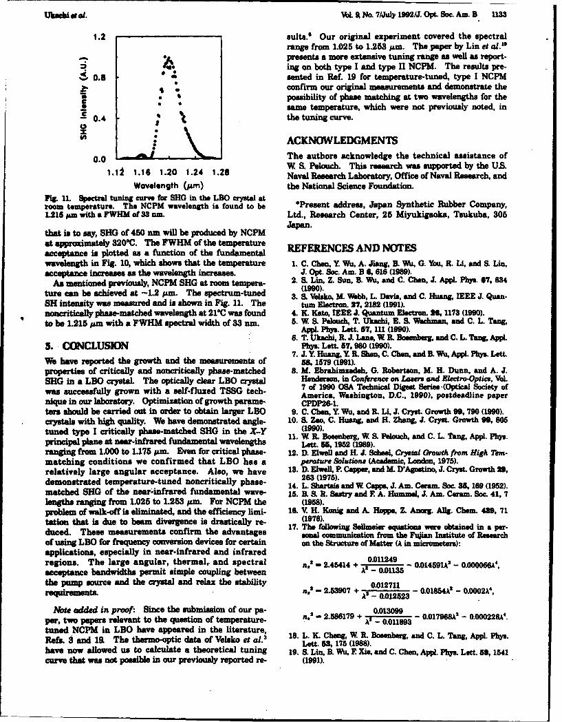
Uhssiut eL. VoL A No. 7/July 1992/J. Opt. Soc. Am. B 1133
1.2 sults.1 Our original experiment covered the spectralrange from 1.025 to 1.253 pm. The paper by Lin et al."
,-, "L presents a more extensive tuning rang as well as report-0.R ing on both type I and typeflNCPM. The results pre-
.10 0.8 sented in Ref. 19 for temperature-tuned, type I NCPMconfirm our original measurements and demonstrate the
_ .a possibility of phase matching at two wavelengths for theCc same temperature, which were not previously noted, inS 0.4 the tuning curve.(I I : ACKNOWLEDGMENTS
0.0 A The authors acknowledge the technical assistance ofW S. Pelouch. This research was supported by the U.S.1.1:2 1.16 1.20 1.24 1.28 Naval Research Laboratory, Office of Naval Research, and
Wavelength (;Am) the National Science Foundation.Fit. n. Spectral tuning curve for SHG in the LBO crystal atroom temperature. The NCPM wavelength is found to be *Present address, Japan Synthetic Rubber Company,1215 pm with a FWHM of 33 um. Ltd., Research Center, 25 Miyukigaoka, Tsukuba, 305
Japan.that is to say, SHG of 450 nm will be produced by NCPM
at approximately 3200C. The FWHM of the temperature REFERENCES AND NOTESacceptance is plotted as a function of the fundamentalwavelength in Fig. 10, which shows that the temperature 1. C. Chon, Y. Wu, A. Jiang, . Wu, G. You, R. Liý and S. Lin,acceptance increases as the wavelength increases. J. Opt. Soc. Am. B S,8 16 (1989).
As mentioned previously, NCPM SHG at room tempera- 2. S, Lin, Z. Sun, B. Wu, and C. Chen, J. Appl. Phys. 67, 634ture can he achieved at -1.2 pm. The spectrum-tuned (1990).
3. S. Velsko, M. Webb, L. Davis, and C. Huang, IEEE J. Quan-SH intensity was measured and is shown in Fig. 11. The tur Electron. 27, 2182 (1991).noncriticaily phase-matched wavelength at 210C was found 4. K. Kato, IEEE J. Quantum Electron. 26,1173 (1990).to be 1.215 Am with a FWHM spectral width of 33 rnm. 5. W S, Pelouch, T. Ukachi, E. S, Wachman, and C. L. Tang,
Appl. Phys. Lett. 57, 111 (190).6. T. Ukachi, R. J. Lane, W. P. Bossnbea, and C. L. Tang, Appl.
5. CONCLUSION Phy., Lett. 57, 960 (1990).7. J. Y Huang, Y R. Shen, C. Chen, and B Wu, Appl. Pby.. Lett.
We have reported the growth and the measurements of 5s, 1579 (1991).properties of critically and noncritically phase-matched 8. M. Ebrahimsadsh, G. Robertson, M. H. Dunn, and A. J.SHG in a LBO crystal. The optically clear LBO crystal Henderson, in Conference on Laren and Electro-Optice, VoLwas successfully grown with a self-fluxed TSSG tech- 7 of 1990 OSA Technical Digest Series. (Optical Society of
America, Washington, D.C., 1990), postdeadline papernique in our laboratory. Optimization of growth parame- CPDP26-1.tars should be carried out in order to obtain larger LBO 9. C. Chen, Y. Wu, and I. Li, J. Cryst. Growth 99, 790 (1990).crystals with high quality. We have demonstrated angle- 10. S, Zoo, C. Huang, and H. Zhang, J. Cryst. Growth 99, 805tuned type I critically phase-matched SHG in the X-Y (low).
1.W R. Bosenbuig,W ,PluhanC.LTngAp.Pbsprincipal plane at near-infrared fundamental wavelengths Lott. 5W 1952 (1989).ranging from 1.000 to 1.175 pim. Even for critical phase- 12. D. Elwell and H. J. Scheel, Crystal Growth from High Tern-matching conditions we confirmed that LBO has a perature Solutions (Academic, London, 1975).relatively large angular acceptance. Also, we have 13. D. Elwell, P. Capper, and M. D'Agostino, J. Cryst. Growth 29,
demonstrated temperature-tuned noncritically phase- 263 (1975).14. L. Shartsai and W Capps, J. Am. Ceram. Soc. 85,169 (1952).
matched SHG of the near-infrared fundamental wave- 15. B S. . Sastry and F. A. Hummel, J. Am. Ceram. Soc. 41, 7lengths ranging from 1.025 to 1.253 pm. For NCPM the (1958).pvrblem of walk-off is eliminated, and the efficiency limi. 16. V. H. Konig and A. Hoppe, Z. Anorg. Allg. Chem. 439, 71tation that is due to beam divergence is drastically re- (1978).
17. The following Sellmeier equations were obtained in a per-duced. These measurements confirm the advantages sonal communication from the Fqjian Institute of Researchof using LBO for frequency conversion devices for certain on the Structure of Matter (A in micrometers):applications, especially in near-infrared and infraredregions. The large angular, thermal,. and spectral n.' - 2.45414 + 0.01135 0.014591k' - 0.000066A',acceptance bandwidths permit simple coupling between A-0.01135the pump source and the crystal and relax the stability 0U012711requirements. n.2 - 2.53907 + A' _ 0.012523 0.01854W - 0.0002k4 ,
Note added in proof: Since the submission of our pa- 20.013M9par, two papers relevant to the question of temperature- n2' - 2.586179 + '- 0.119 - 0.017968A - 0.000226A4.
tuned NCPM in LBO have appeared in the literature,Refs. 3 and 19L The thermo-optic data of Velako et al. 18. L. K Cheng, W R. Bosenborg, and C. L. Tang, Appl. Phys.
Lett. 5•, 175 (1988).have now allowed us to calculate a theoretical tuning 19. S. Lin, B. Wu, E Xis, and C. Chen, AppL Phys. Lett. 59,1541curve that was not possible in our previously reported re- (1991).

4 P
41-)

6 IODULA TORS IN IMODULATE 6 WAVELENGTHS
WITH 1 AOM gets-dirt berm, concrete, wood, can- target. Cohn says, "This level is signif-vas, and sandblasted aluminum-over icantly lower than with previous de-
Low Introductory Price the 9.3-10.7-pm range was measured. vices." Also, calibration of differentialIn addition, data on differential reflec- absorption by measuring atmospherictivitv of contaminants sprayed on sol- water vapor produced results = 5,• ofid targets were obtained. Various the local metrological station, which ischemicals contained in a vapor chain- within the accuracy of that equip-ber at a range of 500 m were moni- ment. Finally, Cohn reports, "The sen-tored (with a solid target 1 km behind) sor could'measure vapor levels of ato study differential absorption. typical simulant (such as triethvlene
Other tests included measurements phosphate) at levels below that ofof aerosol backscatter, transmission passive systems or previous laserthrough dust, range of distant topo- sensors."graphical features, and the system The Army has awarded Hughes anoise level as a function of the number follow-on program to improve the la-of pulses averaged. These tests pro- ser and sensor. ReducirS the size andduced a great deal of data (at least 200 weight are immediate goals, and addi-Mbyte) that will take several months tional field tests will be performed.to analyze completely. The program extension is expected toNEW POLYCHROMATIC Preliminary results are encouraging. continue through mid-1994. Commer-The system noise level, determined cial environmental applications in-from the standard deviation of nor- clude industrial-chemical emissionACOUST&O PTic malized return signals, was 1%-2% and urban-pollution monitoring.for a four-pulse average against a solid Heather W. Messenger
MODULATIONSYSTEMS PULSED TUNABLE SOURCES high-energy dye lasers.
With this in mind, engineers atCommercial OPO produces Spectra-Physics Lasers (S-PL, Moun-
t altain View, CA) have developed aMODULATES UP TO SIX high-energy tunable output high-energy Nd:YAG-pumped OPOWAVELENGTHS SIMULTANEOUSILY device that is tunable from 400 to 3000FOR Ar'I/r" LASERS Researchers needing a high-energy nm and that can be frequency doubled
tunable source typically resort to to 200 nm, according to Mark Sobey,Nd:YAG- and excimer-pumped dye general manager of S-PL's Quanta-
MOST COMPETITIVELY lasers, notwithstanding the relative Ray business unit. The device willPRICED inconvenience and "user-unfriendli- eventually become an extension of the
ness" of dye lasers. Optical parametric recently released MOPO-700 series of* OEM DRIVER MODULES oscillators (OPOs) appear to offer an OPOs and Will further increase the
OPTION attractive solid-state alternative to Continued on p. 20
* EASY TO USE
" FAST FACTORY SUPPORT
A MUST FOR LASER LIGHTSHOW SYSTEM AND LASERDISPLAYS
IU
Integrating Lasers, Electronics 5and Acousw-Optcs
NEOS TECHNOLOGIES, INC.4300-C FORTUNE PLACE
WEST MELBOURNE, FL 32904FIGURE 1. Commercial OPO consists of a delay line (fight), a master oscillator (center), a power
(407) 676-9020 TELEPHONE oscillator (left), and a wavelength separator (rear). Not shown is the pump laser, an injection-seeded(407) 7224499 FACSIMILE Nd:YAG model.
Is aRCLE NO. 9

Continued from p. 16 of a Type I doubler makes it possibleS A I I tuning range and reduce the linewidth to obtain more than 400 m) at 355 nm
of these products, which currently from the pump laser. "To the user thisprovide high-energy (>100 mJ) output means the overall system efficiency,with narrow linewidth (<0.1 cm"n) at and its cost, are similar to those ofwavelengths from 400 to 2000 nm (see Nd:YAG- or excimer-pumped dye Ia-Fig. 1). sers,, says Sobev.LASERS Briefly, OPOs are nonlinear optical In the S-PL M:PO design, the mas-•• Iconversion devices that use a nonlin- ter and power oscillators each use a
ear crystal to achieve frequency con- BBO crystal as the parametric conver-version when pumped by a laser. The sion medium (see Fig. 2). The masterS-PL development work on OPOs us- oscillator generates a linewidth-nar-ing beta-barium borate (BBO) as the rowed seed beam of low energy,nonlinear crystal has been done in which controls the linewidth of the
7- collaboration with C. L. Tang and his high-energy beam generated in thegroup at Cornell University (Ithaca, power oscillator. All of the outputNY). The Cornell Research Founda- energy is generated in the power oscil-Vtion owns a fundamental patent titled lator, so the OPO output energy is"Tunable Optical Parametric Oscilla- constant and independent of thetor" (US Pat. #5053641) covering the linewidth. Current S-PL productsuse of BBO in any type of OPO, to specify energies exceeding 100 mJ hwhich S-PL has recently been granted with less than 0.1 cm" linewidths, and r
CU1WIEI"C0NT10LOtMRAQO an exclusive license. Sobey says S-FL S-PL engineers have already observedhas filed for patents on several aspects linewidths less than 0.02 cm"1 at simi-of its OPO design, including the mas- lar output energy and wavelengths.ter-oscillator/power-oscillator (MOPO) Two variants of the master-oscilla-approach to narrow-linewidth, high- tor design are intended to addressenergy devices, different application requirements.
Each uses a short grazing-incidenceSystem design cavity design, with a servo system to
, 1%P.P The third harmonic from a 1250-mJ control and couple the rotation of theSNd:YAG laser pumps the OPO. The BBO crystal with the diffraction-grat-
Nd:YAG pump beam must be line- ing angle. A small portion of the 355-narrowed to control the bandwidth of nm pump energy is split off and usedthe OPO output beam. This is accom- to pump the oscillator above thresh-plished using a single-frequency di- old. The grating/mirror pair controlsode-pumped Nd:YVO4 (vanadate) in- absolute wavelength and linewidth,
U CONTR0LM=M,. jection-seeding laser. A by-product of and the servo system ensures thatthe injection seeding is smoothing of optimal conversion efficiency is main-ACTIVELY-STABILIZED,,1 , the Nd:YAG laser temporal profile, tained as the wavelength is scanned
"Mode| 81 28 Features: '" which results in a substantial (>40%) within the master oscillator.. .. • .,.. .•- . ..,• - increase in the 532- and 1064-nm mix- Use of a similar cavity design, but
ing efficiency when generating the with an additional precision mechani-355-nm third harmonic. The addition cal stage and more-complex servo
9oMw Modelt 3A615.20Wft ..* <1%puk4opu kw ned
% 1.poi , i ddlmIany2hr. U.
2 .20/30 IV•AC 3z.hlu 5010 1kýThe~seelhec-ereu 6-' A.1
h.FIGURE 2. Third-harmonic beam (355-nm) from an injection-seeded Nd:YAG pump laser entersmaster oscillator to create linewidth-narrowed low-power beam that is injected into poweroscillator and frequency-converted in 180. High-energy OPO signal and idler output beams canbe tuned over the 400-2000-nm range.
30 CIRCLE NO. 13 L,.

- BE1TERBEAM electronics, makes single-mode output achieve a frequency-doubling conver-
D AGN O STIi CS Npossible. In this case, the system con- sion efficiency exceeding 15,; whenDIS tinous monitors the cavity length covering the 200-400-nm range. HeI__ _and isolates a single longitudinal also says that existing OPO products
mode as the wavelength is scanned. have been designed with doubling in772 In both cases, the MOPO design ap- mind, so they will be able to accom-
parently achieves an overall conver- modate a doubling stage when it be-sion efficiency exceeding 20%. comes available. At the longer end of
Now Indludes BCAO Software Extending the wavelength range be- the wavelength range, an additionallow 400 nm will require frequency set of optics will eventually enable the
$1495 Value! doubling of the OPO output. Based on existing products to tune from 2000 toresults from existing R&D systems, 3000 nm.Sobey says S-PL engineers expect to Stephen G. Anderson
DMCTOR ELECTRONICS
IR readout electronics capture focal-plane-array signalshniproveitients in detector electronic read- peratures, silicon complementary met-out systems parallel advances in focal- al-oxide semiconductor (CMOS) cir-plane-arraj detector stlsteins. The SPIE cuits can be used in most applications.Aerospace and Remote Sensing Sminpo- The development of CMOS-like corn-sihu'n, to be held in Orlando, FL, 12-16 plementary-heterojunction FETsApril 1993, includes a session devoted to (CHFETs) fabricated in the GaAs sys-""-'-- readouts and signal processing: "Infrared tern for very-low-temperature applica-detectors and instrumentation." High- tions will be described bv I. Cun-lights of four conference papers are de- ningham, E. R. Fossum, and S. M.
,scribd here by Eric R. Fossumn, a research Baier of the Jet Propulsion Laboratorytechnologist in the Imaging Systems Scc- (JPL, Pasadena, CA) and Honeywell
Pasadena, CA 91109. both p-channel and i-channel transis-tors, which allow the development of
One active area of research in detector low-power cryogenic focal-plane cir- Nithelectronics centers on implementing cuits for space-based astrophysics ap- .cryogenic readout electronics in galli- plications. While the CHFET may re-uum arsenide (GaAs) materials. GaAs semble the CMOS structure in superfi-
* has a lower carrier freeze-out tempera- cial ways, the lack of a true insulatorture than silicon. The freeze-out of such as SiO 2 results in a higher gate-
"* Complete 33M1z 486 Processor carriers is directly linked to 11f noise in leakage current in a CHFET than in100 Mbyte Hard D cryogenic circuits. Thus, GaAs-based CMOS devices. A parametric study of co
circuits can potentially operate with gate-leakage current as a function of"* Over 20 New Diagnostic lower noise and at lower temperatures both material configuration and geom-
Features than their silicon counterparts. etry will be presented by JPL. A simi-The development of GaAs field-ef- lar study on noise in these circuits will
"* Direct Energy/Power fect transistors (FETs) for cryogenic also be described. coMeter Input readout of discrete, nonmultiplexed For most infrared (IR) detector-read-
"* It's a complete 486 DOS based detector arrays will be discussed at the out applications, silicon CMOS is thePersonal Computer aerospace sensing symposium by predominant technology. The use of
R. K. KIrschman and J. A. Lipa of innovative circuits can improve the"* BCAOS - Sofjware package Stanford University (Stanford, CA) performance of the FPA by reducing FIUR
capable of Beamcode Analysis and M. Omori from Microwave Tech- both temporal and fixed pattern noise.operations nology Inc. (Fremont, CA). These Recent progress in low-power analog
small focal-plane arrays (FPAs) would circuits for on-focal-plane signal pro-"* All in the same portable be used on the Gravity Probe B point- cessing will be discussed by B. Pain
package. ing telescope and would operate at and others of JPL. Their paper de-2-3 K. The researchers will report on scribes work on a background-sup-the evaluation of commercial and pression circuit for long-wavelength
4 RIC~FMrLOIES, Inc. foundry GaAs FETs as well as custom IR FPAs that increases effective dy-77e Leader i. Automated Beam GaAs metal semiconductor FETs and namic range by removing the back-
Dia'aficg•Sstenn circuits operating at cryogenic ground pedestal. The circuit also pro-temperatures . vides offset nonuniformity correction.US For larger FPAs, power dissipation Other circuits for low-power, high-
1800 775 1886 is a critical parameter. At higher tern- gain amplifiers and on-chip analog-to-P.O. BOX81 MHoNE WUP3EOW4AN. Itr Ul.WIS. FAX 4% M"224
22 CIRCLE NO. 18

Measurements of noncritically phase-matched second-harmonicgeneration in a L1B30 5 crystal
T. Ukachi,a) R. J. Lane, W. R. Bosenberg, and C. L TangMaterials Science Center. Cornell University, Ithaca, New York 14853
(Received 21 May 1990, accepted for publication 3 July 1990)
The characteristic properties of noncritically phase-matched second-harmonic generation inlithium triborate (LiB3O,, LBO) are investigated. Using an LBO crystal grown in ourlaboratory, we demonstrate that temperature-tuned noncritical phase-matchedsecond-harmonic generation from 1.025 to 1.253 /m is achieved in a temperature range from190 to - 3 TC. The noncritical phase-matching temperature for 1.064 1m radiation isfound to be 148.0 *0.5 TC with a temperature acceptance bandwidth of 3.9 C cm.
Lithium triborate (LiB 305 , LBO) is a newly developed and determined that 0 = 11.4". This value is in good agree-nonlinear optical crystal which is characterized by a wide ment with the theoretical one, 4 11.8', calculated usingtransparency range, small birefringence, a moderate non- the Sellmeier equations.3linear optical coefficient, and a high optical damage The temperature-tuned noncritically phase-matchedthreshold." 2 These unique properties, along with its me- SHG and the angular acceptances were evaluated usingchanical hardness, chemical stability, and nonhygroscopic- 1.064 1m radition from a Nd:YAG laser. Temperature-ity, make LBO an attractive material for certain nonlinear tuned noncritically phase-matched SHG at other funda-optical processes.3'4 For frequency conversion applications, mental wavelengths in the infrared region was also mea-the use of noncritical phase matching (NCPM) is advan- sured using a type I, two-crystal, walk-off compensatedtageous due to the large angular acceptance and the elim- beta-barium metaborate optical parametric oscillatorination of walk-off. Measurements of temperature tuned (BBO OPO)7 pumped by the third harmonic of a com-noncritically phase-matched second-harmonic generation mercial Nd:YAG laser. The BBO OPO can provide con-(SHG) at 1.064 /m have been made on LBO crystals tinuously tunable frared radiation out to 2.5 ism. Thegrown at the 'Uni cntlthe Ffjian Institute h aStructure output beams from Nd:YAG laser and the BBO OPO wereof Matter.c Until recently, the Fujian Institute has been the collimated to a diameter of 2 mm with a divergence half-only source of LBO and very little has been reported about anl of es th n03 m d.T e u d m n alb m w stheir growth techniques. angle of less than 0.3 mrad. The fundamental beam was
In this letter we report temperature-tuned noncritically linearly polarized parallel to the Z axis and propagatedphase-matched SHG from 1.025 to 1.253 pm in an LBO along the I axis.crystal grown in our laboratory. Our measurements of For the measurements of the temperature-tuned non-
temperature-tuned noncritically phase-matched SHG of critical phase-matching properties of LBO, the crystal was1.064 pm radiation show significant discrepancies from enclosed within a copper block equipped with resistivethat reported previously.I heaters and a liquid-nitrogen bath that could maintain the
LBO is a negative biaxial crystal and belongs to the temperature within an accuracy of *-0.5 "C. The tempera-orthorhombic space group with mm 2 point symmetry.5 ture of the crystal was monitored and controlled by ther-The dielectric axes X and Y are parallel to the crystallo- mocouples attached to the side surfaces of the crystal. Thegraphic axes a and c, respectively. 2 The LBO crystal used crystal was heated or cooled at a rate no larger than I "C/in this experiment was grown in our laboratory using the min to avoid temperature inhomogeneity in the crystal. Intop-seeded solution growth (TSSG) technique.6 A Y-cut order to minimize any possible error caused by a temper-seed was introduced into a slightly unsaturated Li 2O-B20 3 ature gradient between the center and the surface of thesolution (91.0% B20 3 by weight) at a temperature of crystal, the incident beam position was set at 2 mm from811 TC and grown for 20 days while cooling to a tempera- the center of the crystal (i.e., I mm from the copper wall).ture of801 S C. From the 20X20X 15 mm3 boule a cube of Figure 1 shows the temperature tuning curve for SHGLBO was fabricated and polished to dimensions at 1.064 pm radiation. The noncritical phase-matching3.9x6.0x4.0 mm3 along the dielectric axes ,. Y. and Z, temperature (T,) was found to be 148.0:0.5 TC with arespectively. All measurements by our laboratory reported full width at half maximum (FWHM) of 10.1 "C, corre-here were made on this crystal. sponding to a temperature bandwidth (A 77) of 3.9 TC cm,
For comparison with the theoretical value, we mea- for crystal length 1. This value of T... for SHG at 1.064sured the type I phase-matching angle for SHG of 1.064 is differs significantly from the previously reported valuepm radiation in the X- Y principal plane (0 = 9(r, 0 is mea- of 112 TC measured using LBO crystals grown at the Fu-sured from the Z axis and # is measured from the X axis) jian Institute of Research on the Structure of Matter.' The
")On leave froin Japan Synthetic Rubber Co., Ltd., Research Ceer, origin of this discrepancy is not fully understood at this
Miyukigaoks, Tsukuba 305, Japan.
960 Awl. Phys. Lett. 57 (10). 3 September 1990 0003-6951/90/360980)03502.00 01990 Ameican Institute of Physics 960

1.2 17, t.2
1.0• o.00.6 0.5
ii 0.5"0.6 C
* .!• 0.4.C.00.4 0.2C .n
0.282 86 90 94 9
0.0 Angle 9 (degrees)120 140 160 150
Temperature ('C) ,-. 1.2
1.0 (b)
FIG. 1. Temperature tuning curve for noncrticai phase matching at the 0.8fundamental wavelength of 1.064 pgm in LBO. Noncritical phase match- Z 0.6iug occuat 148.0-*O.5YCwithaFWHMbmndwidthoflO.1*C. C
0.4-- 0.2
time. However, in this experimental configuration, the Xmeasured temperature may be somewhat different from the () 0.0
-12 -6 0 S 1actual temperature of the crystal due to a temperature gra- An2 - 0dgr12
dient in the crystal. The magnitude of this effect was eval- Angle (degrees)uated by changing the lateral position of the incident beamon the entrance surface of the crystal. When the incident FIG. 2- ftternal a apt for second-haronic geeration ofbeam was positioned on the center of the crystal (3 m- 1.064 p radiation at the noncritical phaae-matching temperature offrom the copper wall), where the temperature is believed 148.0*0.5oc for roation about (a) the Yaxis (Odirection) and (b) the
to be the lowest due to heat radiation from the incident Z a&is (# direction). The FWHMs are 6.6' and 9.1* in the 0 and 4crystal surface, the difference between T•, obtained at directions rpecvely.
this position and that at the original one was less than I "Cand thus was neglected in the following experiments, to higher temperature, for example, 450 nm SH radiation
While maintaining the crystal temperature at will be produced by NCPM at -320 C.148.04-0.5 "C (NCPM temperature for SHG at 1.064 In conclusion, we have demonstrated temperature-ism), the acceptance angles AO and A# were measured by tuned noncritically phase-matched SHG from 1.025 torotating the crystal about the Y axis in the X-Z plane (8 1.253 pm in an LBO crystal grown in our laboratory. Fordirection) and about the Z axis in the X- Y plane (# direc- noncritical phase matching, the problem of walk-off istion), respectively. Figures 2 (a) and 2(b) show the angle- eliminated and efficiency limitations due to beam diver-tuned SH intensity curves in the direction of 0 and 0. The gence is drastically reduced. These measurements confirmFWHM acceptance angles (external) were obtained to be the advantages of using LBO for frequency conversion de-6.6' and 9.1" for the rotation of the 9 and # directions, vices for some applications, especially in the near-infraredrespectively. These values correspond to angular accep-tance bandwidths of A4I042 - 71.9 avo,, &4lin/ - 99.1unrad (cm) 1'2 1.2
Similarly, temperature-tuned noncritically phase- X 1.0)'S A
matched SHlO was measured at the fundamental wave-jlengths of 1.025, 1.100, 1.150, 1.200, and 1.253 pAm which 0.8 '11 -were generated by the B1O OPO. Temperature-tuned SH --Z" i!intensity profiles are shown in Fig. 3. Notice that the .FWHM of the temperature bandwidth increases its the .2 0.4[temperature decreases. Room-temperature (24 C) non. -| * : I"criticalphase matching occurs at a fundamental wave- i 0. .* ! i " ;0 .length of 1.2 pm correspond:ag to 600 nm SH radiation. 0.0 s JFigure 4 shows the temperature dependence of noncritical -50 0 50 100 150 200 250phase-matched SH radiation from 512.5 to 626.5 an as afunction of the fundamental wavelength. Figure 4 indicates Temperature (C)that by using a 1.0 to 1.3 pm source for the fundamental, FIG. 3. Temperature tunng curves for nancriticaily phase-matchedmost of the visible spectrum can be generated under eond-hsamonic generation in LBO at the fundamental wavelengths of
A,=1.025, A,-•1.064, A3,-.10. A,4 =l.l150, A--1.200. andNCPM conditions in a temperature tuning range of 220 to A - 1.253 pm generated by a type 1. two.crstai, walk-of compensated- 20 C. The blue spectrum should be attainable by going EDO optical parametric eamilator.
91e1 App. Phys. Lett., Vol. 57, No. 10. 3 September 1990 Ukachi o at 981
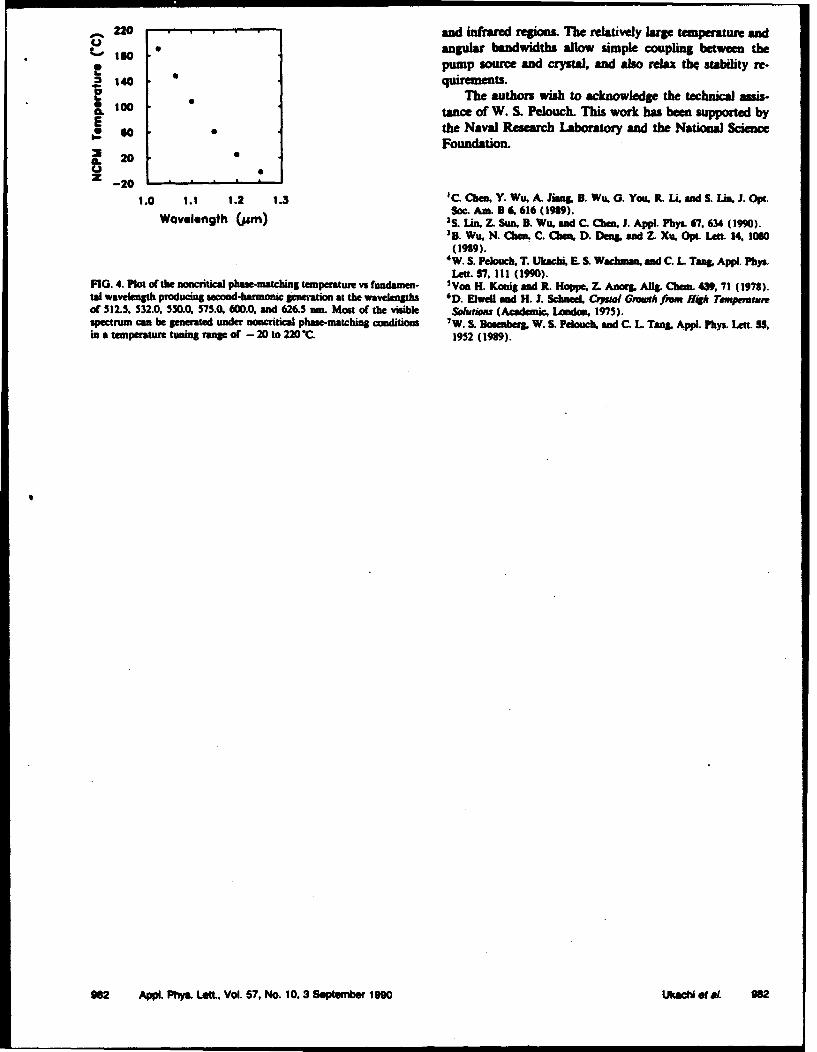
_ 220 and infrared regions. The relatively large temperature ando "angular bandwidths allow simple coupling between the
ISO pump source and crystal, and also relax the stability re-140 quuments.
10 The authors wish to acknowledge the technical assis-1100 tance of W. S. Pelouch. This work has been supported by
s Othe Naval Research Laboratory and the National ScienceFoundation.
IL 20U 0
-20
1.0 1.1 1.2 1.3 'C. Chen, Y. Wu, A. Jim& B. Wu, G. You, R. L, and S. Lin. J. Opt.So.A.B 6. 616 (19M).Wavelength Oj,,) s Lin 7. (19.a9) . J. AppW. ,lys. 67. 634 (1990).
'B. Wu. N. Chem, C. Chen, D. Dens, and Z. Xu. OpL Len. 14, 1060(1919).
4W. S. Pelouch. T. Ukachi, E. S. Wac.man, and C. L Tan& Appl. Pbys,Lett. 57, ii (1990).
FIG. 4. Plot of the noncritical phase-matching temperature vs fundamen- 'Von H. Konig and R. Hoppe. Z. Anorg, Allg. Chem. 439, 1 (1978).tal wavelength producing second-harmonic generation at the wavelengths D. Elwell and H. J. SchneeL Coyrai Growth fiw , Mi Temperatureof 512.5. 532.0, 550.0. 575.0, 600.0. and 626.5 n-. Most of the visible Soludm (Academic. London, 1975).spectrum can be generated under noncritical phase-matching conditions 7 W. S. Bomenberg. W. S. Pelouch, and C. L Tang. Appl. Phys. Lett. 55,in a temperature tuning range of - 20 to 220"(C. 1952 (1919).
9062 Appl. Phys. Let.. Vol. 57, No. 10. 3 September 1990 Ukacdetal. 082
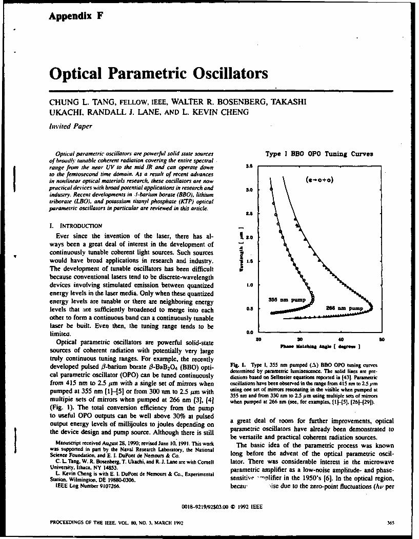
Appendix F
Optical Parametric Oscillators
CHUNG L. TANG, FELLOW, IEEE, WALTER R. BOSENBERG, TAKASHIUKACHI. RANDALL J. LANE, AND L. KEVIN CHENG
Invited Paper
Optical parametric oscillators are powerful solid state sources Type I BBO OPO Tuning Curvesof broadly tunable coherent radiation covering the entire spectralrange from the near UV to the mid IR and can operate down 3.5to the femtosecond time domain. As a result of recent advancesin nonlinear optical materials research, these oscillators are now (e-0+0)practical devices with broad potential applications in research and 3.0industry. Recent developments in .1-barium borate (BBO), lithiumtriborate (LBO), and potassium titanyl phosphate (KTP) opticalparametric oscillators in particular are reviewed in this article.
2.5
I. INTRODUC71ON
Ever since the invention of the laser, there has al- 2-.oways been a great deal of interest in the development ofcontinuously tunable coherent light sources. Such sourceswould have broad applications in research and industry. 1 1.5
The development of tunable oscillators has been difficultbecause conventional lasers tend to be discrete-wavelengthdevices involving stimulated emission between quantized 1.0energy levels in the laser media. Only when these quantizedenergy levels are tunable or there are neighboring energy 355 ampmlevels that are sufficiently broadened to merge into each 0.5 am Rm pumpother to form a continuous band can a continuously tunablelaser be built. Even then, the tuning range tends to belimiteo. 0.0
Optical parametric oscillators are powerful solid-state 20 30 40 so
sources of coherent radiation with potentially very large
truly continuous tuning ranges. For example, the recentlydeveloped pulsed /3-barium borate f3-BaB 204 (BBO) opti- F•g. 1. Type i, 355 nm pumped (..%) BBO OPO tuning cutvesdetermined by parametric luminescence. The solid lines are pre-cal parametric oscillator (OPO) can be tuned continuously dictions based on Sellmeier equations reported in 1431. Parametric
from 415 nm to 2.5 pm with a single set of mirrors when oscillations have been observed in the range from 415 nm to 2.5 itmpumped at 355 nm (1-H51 or from 300 nm to 2.5 pm with using one set of mirrors resonating in the visible when pumped at
355 nm and from 330 nm to 2.5 pm using multiple sets of mirrorsmultipie sets of mirrors when pumped at 266 nm (31, (4] when pumped at 266 nm (see. for examples, 1I-H51, [2614291).(Fig. 1). The total conversion efficiency from the pumpto useful OPO outputs can be well above 30% at pulsed a great deal of room for further improvements, opticaloutput energy levels of millijoules to joules depending onthe device design and pump source. Although there is still parametric oscillators have already been demonstrated to
be versatile and practical coherent radiation sources.Manuscript received Autgst 28, 1990; revised June 10. 1991. This work The basic idea of the parametric process was knownwas supported in part by the Naval Research Laboratory, the National
Science Foundation, and E. 1. DuPont de Nemours & Co. long before the advent of the optical parametric oscil-C. L Tang, W. R. Bosenberg, T. Ukachi, and R. J. Lane are with Cornell lator. There was considerable interest in the microwave
University, Ithaca, NY 14853. parametric amplifier as a low-noise amplitude- and phase-L Kevin Cheng is with E. 1. DuPont de Nemours & Co., Experimental
Station. Wilmington. DE 19880-0306. sensitive -rnifier in the 1950's [6]. In the optical region,IEEE Log Number 9107266. becau, ,ise due to the zero-point fluctuations (hv per
0018-9219/92503.00 0) 1992 IEEE
PROCEEDINGS OF THE IEEE. VOL. 80. NO. 3. MARCH 1992 365

mode per volume) far exceeds the thermal fluctuations (kT The first BBO OPO was reported on at CLEO in 1986per mode per volume), optical parametric amplifiers are by Fan et al. [1], [21 using a 9 mm crystal grown at thenot particularly useful as low-noise amplitude-and phase- Fujian Institute in the Peoples' Republic of China (PRC).sensitive amplifiers even though they are quantum noise It was a doubly-resonant, piano-piano cavity pumped bylimited. Based upon the recently developed concept of the second-harmonic of Nd:YAG at 532 nm with a limited"-squeezing,- through which the quantum noise can be tuning range of 0.94-1.22 jim and a conversion efficiencyselectively concentrated more in either the amplitude or of about 10%. Although this work indicated only modestin the phase-channel, the optical parametric amplifier may performance from a BBO OPO, it was the precursor to aconceivably become a useful low-noise device in the optical whole host of subsequent work.region by putting the signal in the alternative quieter More recently, the related lithium triborate (LBO) crystalchannel, but the practicality of such an amplifier is far has also appeared on the scene [131-415J and is attractingfrom having been demonstrated. The real interest in the considerable attention as a potentially useful OPO materialoptical domain is in the wavelength tunability of the optical [161, [17]. For the UV and visible range, these borateparametric oscillators, crystals are now clearly the materials of choice for OPO
The first proposal and theory of optical parametric os- applications. From the deep red to about 4.5 jim, the nonlin-ciliator were due to Kroll in 1962 (7]. Shortly after the ear crystal potassium titanyl phosphate (KTP) [181-[20] canfirst demonstration of optical parametric oscillation by meet many of the key requirements for OPO applications,Giordmaine and Miller in 1965 [8], there was a period including applications in the femtosecond regime, andof intense efforts at developing such an oscillator into a shows great promise.practical device. The potential of such a device as a useful Even though the growth technologies for all of thesesource of coherent radiation was clear from the beginning new crystals still need improvements, OPO's with remark-to a hard core group of specialists (including at least able performances have already been demonstrated usingone science fiction writer ), and a variety of theoretical these three crystals from currently available sources. Thisand experimental studies were carried out [91, [10]. The article gives a brief review of the operating principle ofpractical development of such an oscillator was hampered. optical parametric oscillators and the current status of thehowever, by the lack of suitable nonlinear optical crystals. development of such devices.
Unfortunately, the development of nonlinear optical ma-terials is a very slow and tedious process, with the discoveryof useful new nonlinear optical materials often depending I1. BASIC CONCEPT [91on luck. This lack of progress in practical developments The optical parametric process is a nonlinear opticalcoupled with over-optimism on the part of some enthu- process in which a pump photon, propagating in a nonlinearsiasts eventually led to considerable skepticism about the optical crystal spontaneously or by stimulated emissionprospects of the optical parametric oscillator as a useful breaks down into two lower-energy photons of frequenciesdevice. In the meantime, progress in the search of new w, and W2 with the total photon energy conserved, i.e.,nonlinear optical crystals was slowly being made, leading W+p = W1 + W2. This simple energy conservation conditionto many new nonlinear crystals (e.g., .3-BaB 2Q4 , LiB3Os, is the basis of the famous Manley-Rowe relation [6] in theKNbO3 KTiOPO4, L-Arginine Phosphate, MgO:LiNbO 3, language of microwave parametric amplifier work. The gainKTiOAsO4, AgGaS2, AgGaSe2 , and TI3AsSe3, etc.) in the mechanism is based upon the stimulation emission process.past decade and culminating in the recent rapid progress in That is, the rate of emission through the nonlinear opticaloptical parametric oscillator technology, parametric process is proportional to the photons present;
Experimental OPO's in the earlier days to be in thus the larger the number of photons emitted, the morethe infrared, and the widely used crystal suffered likely photons will be emitted leading to parametric gain.from severe optical damage problems. E%. on to the It is clear that the frequencies of the two emitted photonsshorter wavelength part of the spectrum had been more cannot be uniquely determined on the basis of this conditiondifficult due to the lack of nonlinear optical materials alone. For a given wp there can be a continuous range ofthat can be phase-matched in the UV. The first nonlinear choices of WsI and W2. This is in fact the basic source ofmaterial to break this wavelength barrier was crystalline tunability of the OPO's. The specific pair of frequencies thaturea. A continuous tuning range from 500 nm to 1.23 lim will result in any given situation is dictated by the momen-was achieved with a single set of mirrors resonating in the tum conservation condition, or phase-matching condition:visible and pumped by the third harmonic (-- 355 nm) of kP = ki + k2 , that must also be satisfied.the output of a Nd:YAG laser [ 11 ]. However, although crys- In a normally dispersive and isotropic medium, the mate-talline urea has very high single-shot damage thresholds, it rial dispersion is such that the momentum or the magnitudesuffers from long-term optical damage problems and was of the k-vectbr of the pump photon is always too largesoon superseded by the new nonlinear optical crystal 3- due to dispersion to satisfy the phase-matching condition.barium borate [121, which is comparatively easy to grow In order to compensate for material dispersion. it mustand has superior crystal properties. be reduced relative to the sum of those of the emitted
photons. The most common approach is to make use ofi Sundivcr.' by David Brin. p. 243. Bantam Spectra Book. 1980. the birefringence in an anisotropic medium to compensate
W PROCEEDINGS OF THE IEEE. VOL. 80. NO 3. MARCH I1902

for material dispersion. In an anisotropic medium, the threshold: and can be grown to sufficiently large sizes. itindex of retraction, and hence the magnitude of the k- is transparent down to 191 nm and has a relatively largevector, of an extraordinary wave varies with the direction of birefringence; it can, therefore, be phase-matched over apropagation. For a negative uniaxial crystal, the magnitude large spectral range, which means a large tuning range indecreases continuously from that equal to the ordinary OPO applications. The effective di-coefficient of BBO is notwave in the propagation direction along the optical axis large, but adequate for OPO applications with reasonableto a minimum value in the orthogonal direction. The requirements on the length of the crystal and the pumpcorresponding change in the magnitude of the k-vector power. Some of the key properties of BBO are summarizedis determined by the birefringence of the medium. Thus in Table I along with the known properties of LBO andif the birefringence is sufficiently large to compensate for KTP crystals. It must be emphasized that because these arethe dispersion, and if the pump beam is introduced as an relatively new materials, some of the numbers listed areextraordinary wave while the signal and idler waves are still subject to confirmation and possibly revision.ordinary waves, a particular pair of frequencies of emitted Nearly all of the BBO OPO experiments reported inordinary photons will satisfy the so-called Type-I phase- the literature so far are based on crystals grown usingmatching condition k-'t) -j°) + k•)) for each orientation a high-temperature flux growth method, mostly from theof the crystal relative to the direction of propagation of the PRC (Fujian Institute for Materials Research and Beijingpump photon. These zre then the unique frequency outputs Institute for Synthetic Crystals), with the exceptions ofof the parametric oscillator for a given pump photon and a the Cornell University work (231, (241 and some of theparticular orientation of the crystal. experiments carried out at Stanford. Commercial sources
As the crystal is rotated, the magnitude of the k-vector in the U.S. have mainly been selling BBO crystals fromor the momentum of the pump photon changes. The fre- the PRC. A number of U.S. companies are developingquencies of the resulting pair of emitting photons will then independent sources of such crystals, some with technicalchange accordingly. This is the basic tuning scheme of support from Cornell and Stanford Universities. Clevelandthe optical parametric oscillators. The bandwidth of the Crystals is now producing high quality BBO crystals andparametric process is determined by either the pump beam appears to be the only commercial source of U.S. produceddivergence or the spectral width over which the phase- BBO crystals. Researchers in NEC, Japan, have recentlymatching condition can be nominally satisfied; that is, the reported successfully growing single crystals of BBO fromphases of the emitted waves are within, say, 7r/2 over the a melt using the Czochralski method (251. Thus while muchinteraction length. In general, the bandwidth varies linearly remains to be done, it is quite likely that BBO crystals willwith the pump beam divergence when the waves do not become more readily available commercially and the costpropagate along a principal-axis direction of the crystal. will come down in the near future.Such a phase-matching condition is called "critical" and the The BBO OPO's are pumped with either the harmon-corresponding allowed interaction length is called "'critical ics of Nd:YAG lasers or XeCI excimer lasers (261-1281phase-matching length." Along a principal-axis, the phase- with injection seeding for narrow linewidth and diffrac-matching is "noncritical" and the corresponding "noncritical tion limited divergence. The OPO performances and thephase-matching length" is not sensitive to the pump-beam optical-to-optical efficiencies achievable in the two casesdivergence; the dependence on the reciprocal of the pump- are comparable for comparable pump beams, as might bebeam divergence angle in this case is of second-order (see expected.Table 1). The corresponding bandwidth of the parametric In the Nd:YAG pumped case, the most versatile practicalprocess is in practice often determined by the physical OPO is currently the third-harmonic pumped BBO OPO.length of the nonlinear crystal. The advantages of noncrit- With the 355 nm pump, the entire near UV to near IR rangeical phase-matching are possibly narrower linewidths and from 415 nm to 2.5 um can be covered with a single set oflonger interaction lengths. mirrors [31-[51 resonating from 415 nm to the degenerate
With suitable nonlinear optical crystals and pump sources, point at 710 nm. Well over 30% total efficiency (in termsvirtually any wavelength ranging from the UV to the mid of useful outputs at the signal and idler wavelengths) hasIR can now be reached with optical parametric oscillators. been achieved using two approximately 1-cm long crystalsThe technology is better developed at the present time for in the walk-off compensated configuration shown in Fig.the near UV to 4.5 pim range, however, largely due to the 2 at a pumping level on the ord~r of 15-20 mJ/pulse. Theavailability of large high quality BBO, LBO, MgO:LiNbO 3, efficiency is now pump pulse-length limited. That is, withinand KTP crystals. For the I to 10 pm range, AgGaS, and the finite pump pulse duration (typically 7 to 10 ns long),AgGaSe, [211, [22] show great promise. the number of passes the signal pulse can make back and
forth between the mirrors of the singly resonant cavity isIll. RECENT DEVELOPMENTS AND CURRENT STATUS limited and is less than that needed for the signal pulse
to developed to full saturation strength. With sufficientlyA.BBO OPO long pump pulses and eliminating such possible practical
Compared to other nonlinear optical crystals. BBO has problems as the thermal lensing effect, the upper limit of thethe advantages of being only slightly hygroscopic. mechani- total efficiency is over 60%. In terms of the output energy,cally hard, and chemically stable; has a high optical damage because OPO's are scalable, the output energy depends only
TANG ct a/.: OPTICAL PARAMETRIC OSCILLATORS 367

Table I Propenies of Some Nonlinear Optical Crystals for OPO Applications. Data shown is at [((64 jim unless oiherise indicated. rrmr.,-,urtaccdamage threshold: I NT.temperaturc-tuning bandwidth: I044-). CPM-critical pha.c-matching acceptance angle: I -/ ,NH.noncritical phase-matchangacceptance angle: I ,,\-SHG bandwidth: 'I; -'-group-velocity dispersion for SHG at h30) nm.
Crystal LBO I - BAiB 2 O 1 1541 KTP 1541
Point group mm2 1441-1461 3m mm2
Birefringence l=, . .G3G [47)-1491 a, = 1.34234 1.73G71.590j ,,, = I.G0310) -v, 1.7395
1 1Gh = 1.t)IS = 1.6305
Nonlinearity (pmroV) 1.1 = 1.6 j471-(491 I.i_ = 1.6 = 5.1). H = 6.5
it = I t1I8 I1 = 1 .7G. ,I, = (.1e1t = 13.7
Transparency (lim) 0. 16 - 2.6 1501. (51] (0.19 - 2.3 0.33 - 4A4
rmax(GW/cm-) - 25 (47-1491 -- 1551 , I5.0
SHG cutoff (nm) 3-33 1521 411 990
1..1T(° C. - t1) 3.9 [531 3 22
cui).CP. 31.3 [531 0.32 13.7
71.9 [531 Not available Not available(tur'd(� )11/2) NCPM @C 148.0-C
(.A(A- .cm) Not available G.G 4.5
I- 6 3130 uti (fs/tani) 240 1521 360 Not applicable
OPO tuning range (nm) 4-11 - 2300 [52] - 413 - 23(0 - .577 - 4400 u11(\p = 333) (A,, = 355) (Ap = -532)
Boule size 20 x 20 x 13 umi" [53) 084 uni x 18 ,, 20 x 30 x 30 nnu•
Growth TSSG (531 TSSG from TSSG from(k - 10OC Na 2 0" •- 9000 C KGP 4 0•3 Flux
(I - 930oc
Predominant Flux [53) Flux and bubble Flux -inclusions &growth defects inclusions inclusions domains
Chemical properties Nonhygroscopic (531 Slightly hygroscopic Nonhygroscopic(m.p. - 834°C) (.1I - n - 923°C) (m.p.-, 934°C)
on the available pump beam energy and should be readily on urea OPO's have been achieved at the University ofextendable to the multi-Joule level. St. Andrews [271, [28]. Continuous tuning range from
Although it has been demonstrated that, pumping with 537 to 720 nm was achieved with conversion efficienciesthe 4th harmonic oi Nd:YAG at 266 nm, the entire spectral approaching 66% over a narrow range near the noncriticalrange from 330 nm to 2.5 lim can be covered with multiple phase-matching condition. For BBO OPO's, the entiresets of mirrors, the mirror coating damage problem at tuning range extending from 354 nm to 2.37 um with266 nm is a serious one [31-[5]. The BBO bulk damage efficiencies on the order of 10% have been achieved. Athreshold at this wavelength is, however, much higher major problem with the excimer laser pumped BBO OPO'sthan that of the mirror coatings that can be achieved reported so far is that the linewidth of the output is ratherwith current UV coating technology. With the pump-beam large. Without any line narrowing scheme, the reportedsteering scheme shown in Fig. 2 and improved coatings, linewidth in a Type-I OPO can vary from approximatelypractical BBO OPO's operating in the 300 to 450 nm range I nm at 480 nm to nearly 11 nm at 600 nm [27], 1281.should be possible. Such sources will be of great interest By comparison, the corresponding linewidths of similarbecause other sources of tunable radiation in this spectral Nd:YAG laser third- harronic pumped oscillators are nearlyregion tend to be inefficient and cumbersome to use. an order of magniude narrower 1291.
Because of the large number of available wavelengths For spectroscopic applications, the linewidth of the BBOin the UV at relatively high overall efficiencies and aver- OPO is an issue. With a 355 nm Nd.YAG laser pump, theage power levels, the gaseous excimer lasers offer great linewidth varies from U.i0 nm far from degeneracy to wellpotential as pumps for OPO's. With a carefully designed over 10 nm at degeneracy. While this may be adequate forXeCI laser at 308 nm as the pump, remarkable results some applications in solids as will be shown later, many-
36•8 PROCEEDINGS OF THE IEEE. VOL. 80. NO. 3. MARCH 1992

S P TOP VIEW• linewidths in the 0.05-0.3 nm range without line-narrowing,elements: as expected. they are much narrower'than thosc
8 ," obtained in the Type I devicesIn addition to nanosecond types of OPO's, there has also
iBBOI BB02 m2 been considerable interest in using BBO OPO's and opticalparametric amplifiers (OPA's) for tunable picosecond pulse
P1 I .generation [311, [321. Narrow band (< 0.3 nm) and highenergy (> 20W 1J) widely tunable (4(X) nm to 2 lim)picosecond pulses with a better than 30Wi efficiency have
TAI TA2 been shown to be possible [31).It is also of interest to mention briefly some recent
SID N \IFM examples of the. applications of BBO OPO's making useCof the tunable radiation in the near IR, where there is a
dearth of high power tunable radiation sources to evaluateother nonlinear optical crystals. Figures 3(a) and (b) showthe measured tuning curves for second-harmonic generation(SHG) in gadolinium molibdate (GMO) at 70' F. They
TAI TA2 show that the noncritical phase matching wavelengths forA) TAA- and B-cut GMO crystals to be at 1.4029 and 1.410
jLm 1331, respectively. Such information is of interest in
FIg. 2. Walk-off compensated two-crystal configuration of BBO the search for efficient SHG crystals in the minimum-OPO with intracavity UV pump beam-steering mirrors. (For a loss and minimum-dispersion regions of optical fibers fordetailed explanation. sec 1291.) long distance communication purposes. Figure 3(c) shows
the temperature-tuning curve for noncritical phase-matching
applications will require much better spectral resolution. SHG in a lithium triborate (LBO) crystal recently measured
Two different approaches have been used to attack the using the tunable BBO OPO output [34).
linewidth problem. The first is to use intracavity dispersive Medical and spectroscopic applications and large scale
elements [29]. The use of intracavity gratings in much the chemical and commercial lidar applications for detecting
same way as in pulsed dye lasers has led to dramatically leaks along gas pipe lines, or for oil exploration, etc., using
reduced linewidth. Generally speaking, without beam ex- BBO OPO's are reported to be under development.
pansion optics, the use of gratings in various configurations B. Lithium Triborate (LBO)can limit the linewidth to on the order of 0.1 nm throughoutthe tuning range. Because the efficiencies of BBO OPO's LBO is a newly developed nonlinear optical crystal which
are now typically pump pulse-length limited, there is a is characterized by good UV transparency, moderate bire-
limit on the OPO cavity length that can be used; this fringence and nonlinear optical coefficient, and a relatively
makes it difficult to introduce beam-expansion optics into high optical damage threshold [131-[151. These unique
the cavity without reducing the efficiency of the oscillator properties, along with its mechanical hardness, chemical
drasticall'y. In the case where the cavity-length is not a stability, and nonhygroscopicity, make LBO an attractive
limiting consideration, much narrower linewidth similar to material for certain nonlinear optical processes. Althoughthose achievable in pulsed dye lasers should be possible. the smaller birefringence in LBO as compared to that in
thos acievblein ulsd de laersshold e pssile. BBQ tends to limit the phase-matching spectral range, it
An alternative approach is to use Type-ll phase-matching also leads to the possibility of noncritical phase-matching
1301 where the signal wave is also an extraordinary wave ald lads t ane angl e fo nc y phase rsin g
k(f') - A-(' + A(U) orc-e+0.I i.nw htti and larger acceptance angle for frequency conversion ap-P = + k2 or , ' + 0). it is known that this plications in the visible and near IR. For OPO applications,
type of phase-matching can lead to narrower linewidth than the possibilities of achieving noncritical phase matchingthat using Type I phase-matching (e - 0 + 0). In BBO, with standard sources as pumps and temperature tuning arewhere the effective d-coefficient for Type II interaction is distinct advantages of this material.considerably smaller (-, 0.8 pN), the difficulty has been to The existence of LBO has been known since 1926 [351.obtain a large enough interaction length in a suitably cut Its usefulness as .a nonlinear optical material was firstBBO crystal. With recent improvements in BBO crystal pointed out by Chen in 1987 136]. All the commerciallysize and OPO design, Bosenberg et al. [301 have shown available LBO crystals have been from the Fujian Institutethat Type 11 phase-matching is a viable means of obtaining (up to 4D80 X 151111113 ) grown by a high-temperature self-narrow linewidth radiation. Using the two-crystal walk-off flux growth method or from Beijing Institute of Syntheticcompensated scheme mentioned earlier (Fig. 2), along with Crystals by a modified flux or flux pulling method. Incrystals cut for the Type 1i interaction that are 17 mm and the U.S., modest sized single crystals have been grown10 mm in length (Cornell grown), they have demonstrated by top-seeded solution growth from a self-flux at Cornelloscillation over the range of 480 nm to 630 nm and 810 and Stanford Universities and as yet there have been nonm to 1.36 lim with conversion efficiencies of 12% and commercial growers.
TAN(; t.g ul: OPTICAL PARAMETRIC OSCILLATORS

1.0
-~0.6
S0.6
0.4
"- 0.2
0.0
1385 1395 1405 1415 1425FUNDAMENTAL WAVELENGTH (NM)
(a)
B-CUT GMO NCPM AT 70 OF
3.0
00.9 r" 7.3 MM
0.6
0.7 Y s A C("(X-c)) . 0
0.1 A - 0.010
I 0.5 II - 0.510)
0.4 C - 1410.3
0.3 0 -0.00003
0.2
0.0
-0.0 0
1380 1335 2300 l335 1400 1405 1410 1415 3420 1425 1430
FUNOAMENTA. WA•LLNGTH (NM)
(b)
220
*J 180
S140
* 100a.E
60g.. 60 S
u 20 0z
-20
1.0 1.1 1.2 1.3 1.4Fundamental Wavelength (jsm)
(c)
Fig. 3. Examples of applications of BBO OPO. The tunahle infrared output of a two-crystalwalk-off compensated BBO OPO was used to determine the wavelengths for noncriticalphase-matching (NCPM) econd-harmonic generation (SHG) in (a) A-cut and (h) B-cut gadoliniummolihdate crystals at 700 F 1331. and (c) the temperature tuned NCPM %econd-harmonic generationcurve of lithium tri•orate crystal 1341.
170 PROCEEDINrS OF THE IEEE. VOL 98). NO 1* MARCH Ivo:
:; - i , i i i

Xu ct aL [16), have recently reported the successful 5.0operation of an LBO OPO with a tuning range of 540 nm 4.5to 1.03 lim at an efficiency of 22.1% (at 503.4 nm) pumpedby the third-harmonic of Nd:YAG laser output using a a6 x 6 x 13.9uu11 crystal grown at the Fujian Institute and 3.5
cut for Type I phase-matching. The linewidth of the LBO ', 3.0oscillator output is rather large. however: 6 nm at 674 nm, " 2.5
for example. Ebrahimzadeh et al. [171, have carried out aseries of LBO OPO experiments by pumping with a XeCI 3 2.0
laser at 308 nm. also using crystals grown at the Fujian 1.5Institute. Tunable radiation throughout the 372 nm to 1.8 1.0 . . . . . . . . . .um range was obtained. A particular feature of their work 40 45 50 55 60 65 70 75 60 85 gois the use made of Type ii and noncritical phase-matching, Phase Mlatchtng Angle (dog)
leading to a narrow linewidth. for example, of 0.15 nm inthe 375 to 387 nm range and an efficiency of 16.5% with (a)a 16 mm long crystal. With the various UV wavelengthsavailable from other excimer lasers, it is potentially possibleto achieve noncritical phase-matching down to 285 nm with 4.0
narrow linewidths and relatively high efficiencies. 5
Comparing to BBO, LBO offers interesting possibilities 2 3.5that are yet to be explored. It is unlikely, however, that one = a.0will replace the other. The choice will depend on the ap-plication and particular engineering design considerations. . 2.5
0
C. Potassium Titanyl Phosphate (KTP) i 2.0 -
Optical nonlinearity in KTP was first discovered at 1.5
Dupont in 1976 by Zumsteg et al. [181-[20]. Since then,KTP has been primarily used as the second harmonic 1.0crystals in many commercial and laboratory laser systemswhere premium performance and reliability are needed 40 45 50 S5 60 65 70 75 80 85 90
(e.g., in medical lasers and in field-portable microlasers). Phase Matching Angle (deg)Recent advances in the growth of KTP has made availablesizable cm long), single domain crystals suitable for thedevelopment of the optical parametric device. Fig. 4. Single-pass parametric generation tuning curves for KTP
Some of the known properties are tabulated in Table 1. in the .s: plane: (a) pumped at 1.053 pm and (b) at 526 nm. Thetuning gap in (b) is from 1.007 to 1.103 lim and can be removedIt is chemically stable and mechanically robust. Optical di- by going to o -,23° plane. (Reprinted from 1181).electric coatings can be readily applied onto polished crystalsurface using standard coating techniques. The single-shot picosecond [38], [391 and femtosecond [401, [411 timedamage threshold for high quality hydrothermally grown domains. In a synchronously pumped picosecond or fern-crystals is sufficiently high (- 30 GW/cni for 30 ps pulse tosecond OPO, the pump beam consists of a train ofat 526 nm) [181-[201 to withstand the optical power density repetitive short pulses each with a spatial extent generallyin an OPO. Efficient frequency conversion in KTP is much shorter than the OPO cavity length. Thus the pumprestricted to Type II interaction with effective nonlinearity, pulses are short traveling-wave pulses through the nonlineard,ff, ranging from 3 to 7.5 pmN. crystal. In an OPO cavity of just the right length. the
In the nanosecond regime, the efficient operation of a signal pulse will meet and be synchronously pumped by theType ii KTP OPO has been reported recently [371. Adiode-pumped Nd:YAG laser is used to pump the OPO at repetitive pump pulses, For the same average pump pulse1.064 lim. With a 15 mm long KTP crystal and a confocal power, the peak pump pulse power can be much higher
resonator cavity, a 1.06 to 1.61 ltm conversion efficiency and thus more efficient pumping of the pulsed OPO canof 35% was achieved, be achieved.
Recently, Vanherzeele [191. [201 has reported the gener- Using a mode-locked Nd:YAG pump. Bromley et a!.ation of broadly tunable (600 nm to 4.5 pim) picosecond 1381 have efficiently operated a synchronously pumpedpulses at the millijoule level by single-pass OPO/OPA in singly resonant KTP OPO. producing tunable 70 ps pulsesKTP (Fig. 4(a) and (b)). Using a picosecond ND:YLF between 1.04 and 1.09 jim with an over-all efficiency of(1.053 ltim) laser as the pump, a single-pass gain in excess 30%.of 106 was reported for a seeded KTP amplifier. The successful use of a nonlinear crystal in OPO depends.
KTP and BBO are particularly suited for synchronously to a large extent, on the successful development of itspumped OPO for short pulse generation down to the crystal growth technology. KTP is no exception. With
TANG e1 al: OPTICAL PARAMETRIC OSCILLATORS 371

the recent advances in the flux growth of' KTP. routine A(KNOWLEDGMENTproduction of KTP boules of 2 x :1 x 51iai are now The authors wish to thank J. Bierlein. C. Chen. M.
possible. Significant further improvements have also been Dunn, M. Ebrahimzadch. J. Y. Huang. Y. R. Shen. andmade in the hydrothermal growth of KTP. Thus the general H. Vanherzeele for helpful discussions and for providing
availability and the usefulness of this crystal should also the background material for this article.
improve significantly in the future.
REFERENCES
D. Ttuahbl Fentto.%ecuod OPO's ill Y. X. Fan. R. C. Echkardt. R. L. By.er. C. Chen. and A.
Jiang. "'Beta-pha.L barium borate optical parametric osoillator."There is u great need for CW femntosecond laser sources presented at CLEO *86. post deadline paper ThT4.
with high pulse repetition rates that are tunable. The only 121 Y. X. Fan. R. C. Eckardt, R. L. Byer. J. Nolting. and R Wal-available CW high-repetition rate femtosecond laser oper- lenstein. "Visible BaBO 4 optical parametric oscillaior pumpcdavailabes at igh-repetitio0n rate ie asedond laer pr at 355 nm by a single axial-mode pulsed source." Appl Pht sares at approximateiy 63(I nm and is based on the CW Lett.. vol. 53. p. 2014, 1988.mode-locked Rh6G dye laser with DODCI saturable ab- [31 L. K. Cheng. W. R. Bosenberg. and C. L. Tang. "Broadl•
sorber With such a fixed wavelength temtosecond dye laser tuneable optical parametric oscillation in 11-BaBO.'" Appl!Phn's. Lett.. vol. 53. p. 175. July 1988.
as a synchronous pump, OPO offers the possibility of 141 W. R. Bosenberg. L. K. Cheng. and C. L. Tang. App. Phs.%.
converting such pulses in the red to a large spectral range Lett.. vol. 54. p. 13. Jan. 1989.
in the deep red to the infrared at effective efficiencies wel 151 W. R. Bosenbcrg. Ph.D. dissenaion. Cornell University. Ithaca.over 25%. KTP is a prime candidate for such an application 161 W. H. Louisell, Coupled Mode and Parametric Electronics.
because of its relatively large effective nonlinear coefficient. New York: Wiley, 1960.However, because of possible pulse broadening due to [7] N. Kroll. "Parametric amplification in spatially extended media
and application to the design of tuneable oscillators at opticalgroup dispersion in the nonlinear medium, the interaction frequencies." Phys, Rev.. vol. 127. p. 1207. 1962.length is severely restricted. For femtosecond pulses, the 181 A. Giordamine and R. C. Miller, "Tuneable coherent parametric
oscillation in LiNbO3 at optical frequencies," Phys. Re%. Lett..KTP crystal length must be on the order of a mm or less. vol. 4, p. 973, 1969.Thus to reach OPO oscillation threshold using a CW mode- [91 See, for example. R. L. Byer. "Optical parametric oscillators."locked Rh6G dye laser as the pump. the KTP crystal must in Treatise in Quantum Electronics. Vol. 1. Nonlinear Optics.
Pts. A and B. H. Rabin and C. L. Tang, Eds.. New York:be synchronously pumped inside the dye laser cavity. Such Academic. 1975.an intracavitv femtosecond KTP OPO has recently been 1101 C. L. Tang, "Spontaneous and stimulated parametric processes."demonstrated by Edelstein et aL. at Cornell [401, 1411. The in Treatise in Quantuw Electronics. Vol. 1. Nonlinear Optics. pis.
A and B. H. Rabin and C. L. Tang. H. Rabin and C. L. Tang,OPO produced stable pulses of -, 10(1 fs short at 101 Hz Eds. New York: Academic, 1975.in the deep red at the mW-level. With one set of mirrors, a (111 See. for example, L. K. Cheng. M. J. Rosker. and C. L. Tang.
in Tunable Lasers, L. F. Mollennauer and J. C. White. Eds.tuning range from 820-920 nm and 1.92-2.54 ptm has been Berlin. Germany: Springer-Verlag. 1987.achieved. With three additional sets of mirrors, the entire 1121 C. Chen, B. Wu. A. Jiang, and G. You. "A new-type ultravioletrange from 7X0 nm to 4.5 lim can be covered. This KTP SHG crystal il-BaBO 4." Sci. Sits. Ser. B vol. 28. p. 235. 19h5.
[131 C. Chen, Y. Wu, A. Jiang, B, Wu. G. You. R. Li, and S. Lin,OPO is the first broadly tunable CW femtosecond generator "New nonlinear-optical crystal: LiB2 ,O5 " J. Opt. Soc. Amer.,
of coherent radiation. Other types of femtosecond OPO's vol. B6. p. 616, 1989.[421 using different crystals and pump sources are sure to [141 S. Lin. Z. Sun, B. Wu. and C. Chen. "The nonlinear opticai
characteristics of a LiBjO3 crystal." J. App. Phys. vol. 67, p.follow. 634. 1990."""
Using OPO's to generate broadly tunable femtosecond (151 Z. Zhao, C. Huang, and H. Zhang. "Crystal growth and prop-pu sfor studies of ultrafast processes is a Promising new erties of lithium triborate," J. CrIst. Growth, vol. 99, p. 805.
pulses s1990.direction of OPO research and device development. 1161 Z. Xu. D. Deng, Y. Wang, B. Wu. and C. Chen. "Optical para-
metric oscillation form LiB3O. pumped at 355 nm." presentedat CLEO '90, Anaheim. CA, May 1990.
IV. CONCLUSION [17] M. Ebrahimzadeh. G. Robertson. M. Dunn. and A. Henderson."Excimer-pumped LiBiO 5 optical parametric oscillators.'" pre-
Optical parametric oscillators are powerful solid state sented at CLEO '90, post deadline paper CPDP 26, Anaheim.
sources of broadly tunable coherent radiation that can CA, May 1990.operate down to the femtosecond time domain. As a result f181 F. C. Zumsteg, J. D. Bierlein. and T. E. Gier. "A New Nonlinear
optical Material," J. Appl. Phys.. vol. 47. p. 4980, 1976.of recent advances in nonlinear optical crystal research, (191 H. Vanherzeele. "Picosecond laser system continuously funeableOPO's are now practical devices with broad potential in the 0.6-4 tim range," Appl. Opt.. vol. 29. p. 2246. 1990.applications in research and industry. Recent developments 1 [201 C. Van der Poel. S. Colak. J. D. Bierlein. and J. B. Brown. "Ef-
ficient type I blue second harmonic generation in periodically
in BBO, LBO, and KTP optical parametric oscillators are segmented KTiQPO4 (KTP) wave guides," presented at CLFOein '90, post deadline paper. CPDP 33. Anaheim. CA. May 1990.
reviewed in this article. Although we have emphasized 1211 Y. X. Fan, R. C. Ekart. R. L. Byer. R. K. Route, R. S. Feigelson.our discussions these three specific types of OPO's to give "AgGaSi infrared parametric oscillator." Appl. Phy.v Lett., vo!.an indication of the current status of the OPO technology 45, no. 4. pp. 313-315, 1984.because of their more recent interests, a variety of other 122) R. C. Ekart. Y. X. Fan. R. L. Byer. C. L. Marquardt. M. E.
Storm. and L. Esterowitz. "Broadly tunable infrared parametricvisible and IR OPO's based on older materials such as oscillator using AgGaSe,," Appl. Phy).s. Letr.. vol. 49, no. II.
LiNbO3 , LilO3 , KNbO3, AgGaS2, AgGaSe,, etc. have also p. 608, 1986.been improved to the point where they are beginning to 1231 L. K. Chen. W. R. Bosenberg, and C. L. Tang. "Growth and
characterization of low temperature phase barium metaboratefind important applications, crystals." J. Cr'st. Growth, vol. 89. p. 553 1988.
372 PROCEEDINGS OF THE IEEE. VOL. So. NO 3. MARCH 1t942

1241 W. R. Btvscnbcrg. R. J. Lane. and C. L. Tang. -Gro~th of [501j C. Chen. Y. Wu. A. Jiang. B. Wu. G. You. R. Li. and S_ Lin.large. high-41ualits behta-barium mctaboraic crystals." J. (iw~. (I.I.2ijim) J. Opt. Soc. Amner.. vol. B6. p. 61h. 1989,Growith vol. 1018. pp. 394-398. 19Y1. 1511 S. Zhao. C. Huang. and H. Zhung. (0. 165-3.2 jim) J. Cr~vit.
1251 Y. Kuwano and H. Kouta. *Bcta-BaB.10 4 crystal grown b% (;rvwdih. vol. 9Y. p. 805. 1990).a new% method.- presented at CLEO 'k)(. Anaheim. CA. Mai. 152) B. Wu. N. Chen. C, Chen. D. Deng, and Z. Xu. Optics~ Lett..I1Y(M). vol. 14. p. 10180. 1989. calculated by using Selimeier equations.
1261 H. Komine. *,Optical parametric oscillation in a beta-barium [531 T. Ukachi. R. J1. La ne. W. R. Bosenberg. and C. L. Tang. J.borate cry stal pumped by a XcCI escimer laser." Opt. Lett.. Opt. Soc. Amer.. vol. B19. July 1992.vol. 13. p. 643. 1988. 1541 L. K. Cheng. W. R. Bosenberg. and C. L. Tang. "Gro%%ih
1271 M. Ebrahimzadeh. M. H. Dunn. and F. Akerboom. ~~ibvand characterization of nonlinear optical crystals suitable (orefficient visible urea optical parametric oscillator pumped h%~ a frequency conversion,- review article in Protrevs tit Crvstia/XeCI excimer laser."~ Opt. Lett.. vol. 14. p. 5601. 1989. GroWth aind Characterization. New York: Pergamon. v ol. 20.
1281 M. Ehrahimzadch. A. J. Henderson. and M. H. Dunn. ~A .9-57. 199(A.excimer-pumped .4-BaB,04 optical parametric oiscillato~r tune- 1551 IH.Nakatani et al.. Appi. P/wis Lett.. vol. 53. p. 2587. Dec. 26.able from 35;4 nm ito 2.3701 jim. J. QPEIai. Elect.. vol. 26. pp. 19H8. estimated surface damage threshold scaled from detailed1241-1252. Juls 1991). bulk damage results reported.
1291 W. R. Bosenberg. W. S. Pelouch. and C. L. Tang. --High-efficiecyc and naffow-line%% idth operation of at t%%o-crystal i-BaB 2O41 optical parametric oscillator.- Aippi. P/.L~ett.. vol.55. p. 1952. 1989.
1301 W. R. Bosenberg and C. L. Tang. -Tvypc 11 phase matching ina A1-barium borate optical parametric oscillator.- App/. P/its. k- -:A Chung L Tang (Feilou. IEEE) received theLett.. vol. 56, p. 1819. 19901.
[311 J. Zhang. Y. Huang. Y. R. Shen. C. Chen, and B. Wu. B.S. degree from the University% of Washing-"Picosecond tuneable optical parametric amplification in barium ton. Seattle. in 1955. the M.S. degree fromand lithium borates.-~ presented at CLEO '90. Anaheim. CA. the California Institute oif Technology. Pasadena.Mav I")0. *in 1956. and the Ph.D. degree from Harvard
Piskraks. . Smlgvvicvus.andA. mbraas on-University. Cambridge. MA. in I19A). As a John1321 A. Psaaa.V mlyvcvsanA.Ubaa.-o-Parker Traveling Fellow from Harvard. he alsot Luu geeato opisecon~d light pulses." Sot. J. Quant studied at the Technical University of Aachen.Elect., vol. 18. p. 155. 1988. emnfrm151901331 For more detailed infoirmation. see K. Kendall. S. K. Kurtz. R. . - emn rm15-90Lane. W. Bosenberg. C. L. Tang. G. Grimouille. L. Oudar. and From 1964) to 1964 he was a Research StaffR. Neurgaonkar. *'Non-critical phase matched second harmonic Member and later Principal Research Scientist
genraton ~-d2(oO4 3 i th ner ifraed.~ i Prc. at the Research Division of Raytheon Company. He has been on the7th it.Svm. oni/i Apliction ofFeroelctris. niv of faculty of Cornell University since 1964. Currently he is the Spencer
IlliInoi t. Urba na-CheAmpliatign. o Jun oe c s Unv of T. Olin Profes~sor of engineering at Cornell and Codirector of the Cor-1 llnoi T.Uacti UR. an e. Wmpig. R.JounberG-. and9C. L ag nell/UCSB/UCSD/RPI Optoelectronics Technology Center.-Measurements of noncritically phase-matched second bar- Dr agi elwo teAeia hsclS ciytev optimonic generation in a LiBIO.; crystal.- .4pp/. Pin's. Lett.. vol. cal Society of America. and a Member of th National Aaeyo57. p. 980. Sept. 1990. Egneig
1351 C. Mazzetti and F. D. Carli. -~Borati anidri di litio. cadmio.piombo. manganesc.*' Gaz:. C/tim. Ital.. vol. 56. p. 23. 1926.
136] C. Chen. in Proc. Jnt. Conf. oni Lasers, Xiamen, China. nos.15-19. Nov. 1987.
1371 L R. Marshall. A. D. Hay, and R. Burnham. "'Highly efficienteye safe laser sources."~ presented at CLEO '90. post deadline 7Walter R. Rosenberg received the B.S. degreepaper. CPDP-35. Anaheim. CA. May 1990). * in physics from Rensselaer Polytechnic Institute.
[381 L. J. Bromley. A. Guy, and D. C. Hanna. "~Synchronously . .Troy. NY in 1984 and the M.S. and Ph.D.pumped optical parametric oscillator in KTP.- Opt. 'oinmutn.. degrees in applied and engineering physics fromvol. 70. p. 35(0. 1989. Cornell Universitv. Ithaca. NY. in 1987 and
[391 S. Burdulis. R. Grit,zonis. A. Piskarskas. G. Sinkevicus. V. -1990. respectivelySirutkaistis. A. Fix. J. Nolting. and R. Wallenstein. "~Visi- .Presently he is with Spectra Technology Inc.ble optical parametric oscillation in synchronously pumped .(STl). Bellevue. WA where he is continuing hisbeta-barium borate."' Opt. Comm,,.. vol. 74. p, 398. l994). .. work in the areas of solid state laser systems and
1401 D. C. Edelstein. E. S. Wachman. and C. L. Tang. "*Broadly . nonlinear optical frequency conversion.tuneable high repetition rate temntosecond optical parametric.)scillator."' Appi. P/pil.v Lett.. vol. 54. p. 1728. 1989.
[411 E. S. Wachman. D. C. Edelstein. and C. L. Tang. "~Continuouswave mode-locked and dispersion-compensated femntosecondoptical parametric oscillator." Opt. Lett.. vol. I5. p. 136. 1990). Takashi Ukachi was born in Hyogo. Japan. on
[421 R. Laenen. H. Graener. and A. Laubereau. '-Broadlv tunable November 3. 1952. He received the B.E. degreefemntosccond pulses generated by optical parametric oscillation.- nbohsc n iegneigfo skOpt. Lett.. vol. 15. p. 9-71. 1990. University. Osaka. Japan. in 197h.
[431 D. Eimerl. L. Davis. S. Velsko. E. Graham. and A. Zalkin. J,.. He started his professional career at TokyoApp. Pins.. vol. 62. p. 1968. 1987. Research Laboratory. Japan Synthetic Rubber
[44] V. H. Konig and A. Hoppe. Z. Anorg. A 11g. C/hin.. vol. 439, Co. Ltd.. Kawasaki. Japan where he was en-p. 71. 1978. gaged in research on the development of con-
[451 M. Ihara. M. Yuge. and J. Krogh-Moe. Yogyo-kvokai-S/u. vol. . ducting polymers. In 1981 he spent a year at the88. p. 179. 1980). Electrotechnical Laboratory. Tsuktiiba. Japan to
1461 Z. Shuquing. H. Cbaoen. and Z. Hongwu. J. Crvs..t. Gwu g/j, study the superconducting organic metals. Fromvol. 99. p. 8(05. 19901. 1988 ito 199(1 he was a Visiting Scientist at the School of Electrical
1471 C. Chen. Y. Wut. A. Jiang. B. Wu. G. You. R. Li. and S. Lin, Engineering. Cornel! University. Ithaca. NY. where his work involved theJ. Opt. S)(x*. Amer.. vol. B6. p. 616. 1989). growth and the evaluation of nonlinear optical crystals. Since 199) he has
[481 S. Liu. Z. Sun. B. Wut. and C. Cher. J. AppI.Pil. vol. 67. been with Tsukuba Research Laboratory. Japan Synthetic Rubber Co. Ltd..p. 634. 1989. Tsukuba. Japan. His current research interests include the development of
149] On the basis of dl. 2.69 x d/1 ,(KDP) and using the value organic nonlinear optical materials and their device applications.1/i,(KDP)=0.39 pm/V according to R. C. Ekart ct al.. IEEE J. Dr. Ukachi is a Member of the Physical Society of Japan and the JapanQuantum Electron. vol. 26. p. 922. May 1990). Society oif Applied Physics.
TANG el at.: OPTIICAL PARAMETRIC~ 0SCILLAIORS31

Randall J. Lane was born in Billings. MT on I L Kevin Cheng receicd lhc B.S, dc..rec inFebruary 7. 1962. He receised the B.S. and M. 7. chemistry trom Boston Unicrsitt. MA in It),,.Eng. degrees in applied and engineering physics and the M.S. and Ph.D. degresc in applicdfrom Cornell University. Ithaca. NY in 1985 and phy,,sics from Cornell Liniserit., Itha•ca. NY in19K8. respectively. 1988.
In 1983. he conducted research on the medical Currentl. he is a Research Stail Member inapplications of the excimer laser at the IBM the Adsanced Material Science Di\ision in theT. J. Watson Research Center. Yorktown. NY. CR&D Department ot the DuPont ('ompjn,.This research was continued the following year His current %ork in"olses the dc'.loprnent ofat New York University Medical Center. NY. single crvs'al, of the nonlinear optical crs\,,alsIn 1985. he spent a year studying the medical KTiOPO4, KTiOAS04. and other related iAo-
applications ot the Ho:YLF laser at the Massachusetts Eye and Ear morphs. and of s'.aveguide devices based on the epitaxial film growthInfirmary, Harvard Medical School, Boston. MA. Since 1'89. he has of these same materials.continued to study the growth and applications of nonlinear opticalcrystals. spucifically Beta-Barium Metaborate and Lithium Triborate atthe Cornell University Material Science Center laser facility under thedirection of Chung L. Tang.
Mr. Lane is a Member of the Optical Society of America.
OI
"•74 ~PRt)Ll'ElDl%(,S OF THI: tEIl. \,t1t •'' \1) St \I\R(tt tIq'

2162 a reprint from Journal of the Optical Society of America B
Appendix G
Recent advances of the Ti:sapphire-pumpedhigh-repetition-rate
femtosecond optical parametric oscillator
P. E. Powers, R. J. Ellingson, and W S. Pelouch
School of Applied and Engineering Physics. Cornell University, Ithaca, New York.14853
C. L. Tang
School of Electrical Engineering, Cornell University, Ithaca, New York 14853
Received December 17, 1992
The details concerning the resonator configuration, crystal parameters, and operating characteristics of high-repetition-rate and high-average-power broadly tunable femtosecond optical parametric oscillators are re-viewed and discussed in some detail. We also report new results on an intracavity-doubled optical parametricoscillator with tunability from 580 to 657 nm in the visible and the first, to our knowledge, high-repetition-ratefemtosecond optical parametric oscillator with the new nonlinear-optical crystal In-KTiOAsO4, which can po-tentially tune to 5.3 jm.
INTRODUCTION the resonator and the orientation of the nonlinear crystal.active new directions of research on opti- The basic OPO cavity is simple. It can be configured as
One of the most teeither a linear or a rng cavity, with or without intracavitycal parametric oscillators' (OPO's) is on broadly tunable dispersion compensation. Since the device is syn-high-repetition-rate femtosecond OPO's. To generate a chronously pumped the cavity length must match that ofpeak power large enough to overcome the OPO's threshold, the Ti:sapphire laser. These geometries are shown inthe first high-repetition-rate OPO was coupled intracavity Fig. 1. Both cavities are singly resonant with single-to a colliding-pulse mode-locked dye laser.2'- This OPO stack mirrors reflecting either the signal or the idlergenerated 100-fa pulses at 80 MHz with -3 mW of average wave. Besides the geometrical differences between thesepower. After this initial development came a rapid im- two configurations, the main feature that sets them apartprovement in design simplicity and performance. The is that as the resonated wave traverses one round trip thefirst externally pumped high-repetition-rate femtosecond pulse passes through the nonlinear crystal twice in theOPO with a high-power hybridly mode-locked dye laser linear cavity and only once in the ring cavity. The advan-permitted considerable design simplification.5 This was tage of the linear cavity is that it permits double passingquickly followed by a demonstration in which the OPO was of the pump in the nonlinear crystal. This has led to asexternally pumped with a high-power high-repetition-rate much as a 20% increase in power in the output of the sig-femtosecond Ti:sapphire laser.' 7 With the external-cavity nal beam." When single-pass pumping fails to bring theSTi:sepphire-pumped OPO the design is simple and the per- OPO comfortably above threshold double passing the pumpformance robust. The Ti:sapphire-pumped OPO has gen- may permit the OPO to operate well above threshold, re-erated hundreds of milliwatts in both the signal branch sulting in better stability and power. However, the two(to as much as 680 mW) and the idler branch (to more passes of the signal beam through the crystal lead to morethan 450 mW), adding to more than 1 W of frequency- dispersion of the pulse, of which only the linear group-converted power. The femtosecond Ti:sapphire-pumped velocity dispersion (GVD) can be compensated for by theOPO has also demonstrated extensive tunability,8 making prism sequence. The losses from the extra pass throughit an extremely attractive device for femtosecond applica- the crystal are more than compensated for by backreflect-tions. In this paper we present a detailed description of ing the pump. The linear cavity with a backreflectedthe design parameters and the operating characteristics of pump does require that the Ti:sapphire pump laser be ei-a Ti:sapphire-pumped femtosecond OPO as well as the ther feedback insensitive or optically isolated from themost recent results of our use of this device. hackreflection. We used a Ti:sapphire laser that was con-
figured in a ring for double passing the pump because this
FEMTOSECOND OPTICAL PARAMETRIC configuration was not feedback sensitive.' The ring-ILA RCAV cavity OPO eliminates the second pass through the crystal
OSCILLATOR CON I TIOSbut does not permit double passing of the pump. WhenDESIGN CONSIDERATIONS pumped high enough above threshold, the ring-cavity-
Included in the considerations for designing a femto- OPO operation is as robust as the linear cavity with
second Ti:sapphire-pumped OPO are the configuration of feedback.
0740-3224/93/112162-06$06.00 0 1993 Optical Society of America

(a) •than the acceptance angle of the crystal, which then re-duces the efficiency of the phase-matched interaction.The angular acceptance can be calculated by plotting thefunction
(b) sn(Ak4,/2)]
Ak-k,-k.-k, (1)
as a function of the phase-matching angle, where Ak is the<Q -puism phase mismatch and 1, is the crystal length. The fulli .*0 7avto width at half-maximum (FWHM) gives the angular accep-
Fig. 1. Schematic of (a) a linear and (b) a ring OPO cavity with tance. For a 1-mm-thick crystal the angular-acceptance(solid lines) or without (dashed lines) intracavity-prism dispersion angle for KTP in the x-z plane is 0.75* for a pump wave-compensation. The Ti:sapphire pump laser is not shown because length of 780 nm and a signal wavelength of 1.3 jim. Ifits alignment to the crystal depends on whether a type-I or atype-ll interaction is chosen and whether the e wave or the o wave the OPO's beam diameter is 1 mm, then the focus thatis resonated. Note that for a round trip the pulse passes through matches the crystal's angular acceptance is 7.6 cm (R -the crystal twice for the linear cavity and only once for the ring 15.2 cm).cavity.
z
The alignment of the Ti:sapphire pump with the OPOcavity depends on whether the o wave (idler) or e wave(signal) is resonated. When the idler is resonated the Ypump and idler should be collinear to maximize the gain. -
Resonating the signal, however, requires determining howthe Poynting vector of the signal walks off the pump.Wachman et al.s first noticed that the OPO oscillated suchthat the Poynting vector of the pump and signal werecollinear. Hence the pump must be offset from the signal ,,to permit the Poynting vector of the signal to walk ontothe pump. This is accomplished by use of a noncollinearphase-matching geometry such that the noncollinear anglebetween the pump and the signal is equal to the negativeof the walk-off angle. The Poynting vector of the signalthen walks onto the pump wave and not away from it.The crystal orientation is shown in Fig. 2. Figure 3 plots KIP Crs
the value of the Poynting-vector walk-off as a function of (b)the phase-matching angle. In the case of large phaLe- Fig. 2. Crystal orientation. (a) The angles 9 and 4 are defined.matching angles this walk-off is small, permitting align- (b) The alignment of the KTP crystal for a type-H interaction inment of the pump through one of the OPO-cavity mirrors. which the e wave (k.) is resonatedL The pump (k') and k. lie inFor smaller phase-matching angles the walk-off angle in- the x-z plane at a noncollinear angle that is equal to the negative
of the walk-off angle p. k. is oriented so that its Poynting vectorcreases, and the pump and OPO-cavity mirrors must be walks onto the pump.positioned to permit this walk-off. For example, the non-collinear angle for KTP with a type-II interaction is 2.90 3.0
at a phase-matching angle of 450. Using cavity mirrors ofR - 10 cm curvature would then require that the pumpand signal beams be -4 mm apart at a distaLi.e of 5 cm
from the KTP crystal.Suitable focusing parameters for the OPO cavity and U.
the Ti:sapphire pump are determined by considering therespective focused beam sizes inside the crystal and the 1 .angular acceptance of the crystal. The theoretical calcu- Ilations of Cheung and Liu' show that, for a configurationin which the Poynting vectors of the pump and resonated • 1.0
wave are collinear, their focused beam sizes in the crystalshould be approximately the same. The number of pos- oSsible focusing combinations that result in equal beamsizes of the pump and signal in the crystal is limited by 0 __.. . . . . . . .the fact that not all these focusings will permit oscillation. 4 so 53 60 65 70 75 so s5 90
As the beam waist increases, the peak intensity decreases Pa - mating angle (des)
eventually to a point below the OPO threshold. At the Fig. 3. The Poynting-vector walk-off of the signal from the
other extreme, when the focused beam size decreases, pump is plotted as a function of the phase-matching angle for athe angular spread of the focused beam becomes larger 780-nm pump and a noncollinear angle of 2.8*.

2164 J. Opt. Soc. Am. B/Vol. 10, No. 11UNovember 1993 Powers et al.
4.0 function of the phase-matching angle 0 and are shown inPUuP WsvCIes Fig. 4. From this figure it is clear that KTP has a broad
3.5 90 M tuning range, but to have access to the whole range re-730 quires either tuning the pump or changing the crystal
3.0 0 wave phase.matching angle. The Ti:anpphire-pumped OPO of-.... ....... .fers the advantage that the Ti:sapphire laser itself is tun-
S25 able, which leads to broad tunability in the OPO. As seenin Fig. 4, tuning the Ti:sapphire laser can lead to a sub-
2.0 stantial change in wavelength in the OPO. For the regionin which 0 is <550, tuning the pump leads to a largechange in the e wave's wavelength but only a small change
".. in the o wave. In this region one accomplishes tuning to1.0 e wave the longer wavelengths of the o wave by simply changing
,_ _ ,_ , _ , _the phase-matching angle. For angles that are >55*, inwhich d.r is largest, changing the phase-matching angle
40 50 60 70 80 90 leads to a small change in wavelength, so in this regionPhase-matching angle (degrees) tuning the pump makes more sense.
Fig. 4. Tuning curves for a type-Il interaction in KTP with a A consideration that has a direct bearing on the perfor-noncollinear angle of 2.8. The tuning curves for three pump mance of the OPO is the magnitude of the inverse group-wavelengths covering a large part of the Ti:sapphire's tuning velocity mismatch (GVM) between the pump, the signal,range illustrate the effect of tuning the pump. and the idler waves. The GVM is approximately -25 fs/
mm between the pump and the signal and -200 fs/mmIn an attempt to optimize the focusing, we varied the between the pump and the idler for the majority of the
cavity focusing mirrors from R - 7.5 cm to R - 20 cm; tuning range. This puts a limitation on the crystal'scorresponding to these changes we varied the pump focus thickness. The crystal should be thick enough to providefrom R - 10 cm to R - 30 cm so as to keep the signal- to high gain but thin enough to limit the effect of GVM.pump-beam-waist ratio approximately constant. We Additionally, the crystal should be thin enough to phasefound that with mirrors with a higher radius of curvature match the bandwidth of the ultrashort pulse. We gener-the OPO operated nearer to threshold and that at too tight ated pulses as short as 57 fa by using a 1.15-mm-thicka focus the OPO would not oscillate at all (at R - crystal, with 115 mW in the signal beam. With this 1.15-7.5 cm). Our best performance has been with either mm-thick crystal we measured up to 60% pump depletion.R - 10 cm or R - 15 cm for the OPO-cavity mirrors and Although using a thicker crystal will increase the inter-either R - 15 cm or R - 25 cm, respectively, for the pump action length and will lead to more power, this has thefocusing mirror. potential of broadening the OPO pulses. The FWHM
of Eq. (1) plotted versus wavelength gives the phase-CRYSTAL ORIENTATION matching bandwidth. The phase-matching bandwidth for
a 1-mm-thick crystal of KTP is 33 nm at a signal wave-Critical to the successful operation of a femtosecond OPO length of 1.3 pm; this has a transform-limited pulse widthis the orientation of the nonlinear crystal. In this section of 53 fa, assuming a sch2 pulse shape. Increasing thewe use the properties of the nonlinear crystal KTP as an crystal thickness to 1.5 mm decreases the phase-matchingexample to clarify how to determine the alignment that bandwidth to 22 nm, and consequently the transform-maximizes the gain. The first consideration is to orient limited pulse width is 80 fa.the crystal such that the effective second-order nonlinear-ity, d.ff, is maximized. For KTP, d.f is approximated byu OPERATING CHARACTERISTICS
Type I d.w - 1/2(d15 - d24)sin(20)cos(2#), (2) When the OPO is pumped sufficiently above threshold
Type II d.6 - -[d 15 sin'(0) + d24 cos2(0)]sin(0), .(3) (1 W at 100 fs or better), the output of the OPO is a stablepulse train. The average-power fluctuations and pulse-
where 9, the phase-matching angle, and 0 are defined as to-pulse variations of the OPO are determined almost en-in Fig. 2 above. For KTP the values of d15 and d24 are tirely by the Ti:sapphire pump laser. Even without an2.04 and 3.92, Asspectively.18 For these values the type-II active cavity-length stabilizer to length match the OPOinteraction always has a larger ddr than does the type-I and Ti:sapphire cavities continuously, oscillation can beinteraction. For the type-H interaction dfr is maximized maintained stably for as much as several hours. Operat-for # - 0 so that the KTP crystal is aligned such that the ing near threshold decreases the stability of the OPOparametric interactions occur in the x-z plane. It is clear pulse train, as does operating near 0 GVD.from Eq. (3) that one maximizes d.r for the type-. inter- The OPO pulses are characterized by a chirped and anaction for a phase-matching angle of 900; however, it is unchirped regime. The chirped regime is encounteredsometimes advantageous to phase match at smaller angles. when the cavity is operated with a net positive GVD, andSpecifically, wavelengths that are not available at larger the unchirped regime occurs with net negative GVD.angles are accessible at smaller phase-matching angles, as With intracavity dispersion compensation it is possible toshown in Fig. 4. vary the GVD from net negative values to net positive val-
The tuning curves for KTP with 0 - 0 and for various ues. We observed a flip from chirped pulses to unchirpedpossible Ti:sapphire pump wavelengths are generated as a pulses as we changed from negative to positive net GVD.

MCI KTPdestroy the pulse-shaping process. We&gsnerW1u - iJM MCI of 240 mW of sub-100-f. pulses at a wavelength of 647 nm
MC2 SHO and demonstrated tuning of the output from 580 toM2 BOR 657 nm. Because of the optical-power limiting by the
nonlinear loss of the SHG," the output of the intracavity-doubled OPO is very stable and quiet. Although no quan-titative noise measurements have been made, the outputpulse train of the SH is as quiet as the Ti:sapphire laserwhen viewed on a fast oscilloscope.
.W. 81 MHz5 The intracavity-doubled OPO, which uses a 1.5-mm-FTa-pohr Lm, D - 115h thick KTP crystal that is cut for type-II (o --* e + o) phase
[ .=-0 • matching (0 - 45*, -0) in the x-z plane, is shown inFig. 5. We add to the ring cavity an additional intracavity
Fig. 5 Ti:sapphire-pumped intracavity-doubled KTP OPO. The focus of R - 10 cm mirrors that are high reflectors cen-Ti:sapphire beam is focused by the R - 25 cm pump mirror (PM) tered at 1.3 j•m and that transmit -80% of the SH wave-onto the 1.5-mm-thick KTP crystal. The KTP gain crystal is cutat 9 - 45% 0 - 0* for type-li phase matching in the positive re- length. After aligning the OPO with the additionalgion of the x-z plane. The OPO curved mirrors (MCI, MC2) at intracavity focus, we use the OPO-signal beam, takenthe gain and frequency doubling foci have radii R - 15 cm and through a 1% output coupler, to align the 47-jsm-thick P-R - 10 cm, respectively. Two pairs of SF-14 prisms (P) spaced BaB2O4 (BBO) Brewster-cut crystal for SHG using type-I20 cm tip to tip are used for intracavity dispersion compensation.The single SHG output is transmitted through the OPO high re- phase matching. Next we insert the thin BBO crystal at
flector (HR) at the doubling focus. OC, output coupler; r,, pulse the intracavity focus, regain OPO oscillation, and proceedwidth. to replace the OPO's 1% output coupler with a high reflec-
tor to maximize the SH output power.Near the 0 GVD point the pulses spontaneously jump be- BBO is exceptionally well suited for frequency doublingtween chirped and unchirped pulses, leading to instability of ultrashort pulses in the wavelength range of the signalin the pulse train, branch of the OPO. The phase-matching curve for SHG
Accompanying the signal and idler outputs are several in BBO is shown in Fig. 6(a). We refer to the point on thenon-phase-matched processes. Non-phase-matchedsecond-harmonic generation (SHG) of the signal wave(e + e -- e), as well as noncollinear non-phase-matched. 8,sum-frequency generation between the pump and the sig- Lnal wave (o + e -- o), have been identified.47"' We havealso identified the noncollinear non-phase-matched sum-frequency generation between the pump and the idlerwave. The power in this beam is less than a milliwatt. It 40is interesting that this wavelength is equal to the non- Iphase-matched second harmonic (SH) of the signal beamwhen the signal beam equals 1.5 times the pump beam.We have observed this with a 867-nm pump and 1.3-Amsignal. With the signal and idler pulses this gives five O0 1.0 .0 3.0 4A 5.0
synchronous wavelengths. Fundamental Wavelenuth (Pm)(a)
RECENT ADVANCES1.0
Our most recent efforts have been directed toward gener-ating exceptionally high output powers and broad tunabil-ity. For the high-power result we used a Ti:sapphirelaser, producing 2.4 W of average power with a 115-fapulse width. With this pump source we generated 130-fs, 03
680-mW pulses in the signal branch by using a linear- "cavity OPO configuration and a 1.5-mm-thick KTP crys.tal. This is excellent conversion efficiency and is nearthe Manley-Rowe limit. The Manley-Rowe relation &0.states that the number of pump photons that are annihi- 0.0 1.0 2.0 3.0 4.0 5.lated is equal to the number of signal-idler photon pairs Fundamental Wavelength (pun)that are created.5 The limit for a 2.4-W pump at 780 nm (b)and a signal wavelength of 1.3 #Lm ;'ields 720 mW in the Fig. 6. (a) Phase-matching angle versus fundamental wave-signal beam. length for type-I SHG in BBO. The degenerate point at which
Using intracavity frequency doubling, we have extended the phase-matching angle is minimized and phase matches ainto the visible the wavelength range that is accessible to single wavelength occurs at 1.47 pm. The SHG phase-matching
femtosecond OPO pulses. Because the Ti:sapphire- bandwidth becomes very large near this degenerate point.m na - (b) The SHG phase-matching spectrum for 4 - 55 nm BBO crys-
pumped OPO is synchronously pumped, the nonlinear loss tal (47-pm-thick crystal at Brewster's angle) that was phaseof the SHG to the intracavity OPO-signal pulse does not matched for SHG at 1.3 and 1.65 pm.

2166 J. Opt. Soc. Am. B/Vol. 10, No. U/November 1993 Powrer a•a.
In the case of our ultrathin 47-prn-thick BBO crystalthe phase-matching bandwidth for 1.3 pm is shown in
P Fig. 6(b). The two sinc2(AkL,/2) SHG phase-matchingcurves (at A - 1.30 pm and A - 1.65 pin) have merged togive a FWHM SHG bandwidth of 1514 nm. Our observa-tions of the intracavity-doubled OPO agree: after tuningthe OPO from 1.2 to 1.3 #m, rotating the phase-matchingangle of the BBO has no effect on the SHG conversionefficiency. Once the BBO crystal is aligned to double
560 580 6 62 640 N0 60 near the center of the OPO-signal tuning curve, tuningWavelength (0m) the SHG is accomplished by simply tuning the OPO with
(a) no adjustment to the BBO phase-matching angle.As mentioned above, the intracavity-doubled OPO is a
stable source of femtosecond pulses in the visible. Fig-ure 7 shows spectra from the demonstrated tuning rangeand a real-time interferometric autocorrelation of the SHGoutput. The pulse shape of the OPO fundamental is simi-larly clean and quiet. The Ti:sapphire-pumped femto-second OPO and the intracavity-doubled OPO demonstratevery powerful nonlinear-optical-generation techniquesthat will continue to increase in importance as pumpsources are improved and as new pump sources aredeveloped.
(b) To extend the tuning range to longer wavelengths, be-
Fig. 7. (a) Intracavity-doubled KTP OPO spectra within the yond 4 Am, we have demonstrated optical parametric os-
demonstrated tuning range of 580-657 nm. (b) Real-time inter- cillation with the new nonlinear crystal In:KTiOAsO4
ferometric autocorrelation for 240-mW total SH produced, at 115- (In:KTA). In:KTA is very similar to KTP but has a largerfM pulse width, centered at 647 nm. Although not shown, transparency range, which extends to U3 pm. In:KTAsextracavity two-prism dispersion compensation compressed the transparency range has no absorption bands as does KTP,pulses to 95 fs with no degradation in pulse shape. for example, at 3.5 pm." Figure 8 shows that phase
matching over the transparency region for In:KTA is pos-
Pum Wavelength sible out to 53•jm. The In:KTA OPO is aligned in the... Pump w.vet. . same way as the KTP OPO.7 A 1.5-mm-thick In:KTAS- 9-- m crystal is oriented for a type-U1 interaction with a phase-
770m matching angle of -50'. The e wave is resonated in a
7 0mlinear cavity with prisms with a noncollinear angle that is
equal to the negative of the walk-off angle of 2*. We pro-duced pulses at 1.435 /pm in the signal branch and
S.....1.662 pm in the idler branch with a 770-nm Ti:sapphire,....o.....,...............o... °"........ .. o.o.
S.. ...... pump. This is the first demonstration, to our knowledge,of a high-repetition-rate OPO with In:KTA, and, as shownin Fig. 8, tuning beyond 4 pm is possible with the appro-
...... priate crystal cut and mirror coatings.,
,.° ....... .. .o
CONCLUSION40 50 60 70 so 90
Phm matchinl angle (degrees) The high-repetition-rate Ti:sapphire-pumped femto-Fig.& Tuning curves for a type-Il interaction in In:KTA with a second OPO is a robust device that is capable of high aver-noncollinear angle of -2.8°. The tuning curves for three pump age power and short pulse widths, tunable from the visiblewavelengths covering a large part of the Ti:sapphire's tuning to the mid-IR. This device produced unchirped pulsesrange illustrate the effect of tuning the pump. with powers as high as 680 mW, pulse widths as short as
57 fs, and tunability from 580 to 657 ni in the visible asphase-matching curve at which the slope is zero as the de- well as from 1.16 to 2.2 pLm in the IR. In the near futuregenerate point. Interestingly, at this degenerate point in we plan to extend this tuning range to 5 pm with In:KTA,the phase-matching curve, which occurs for BBO at and we are looking at other new materials that would per--1.47 pm, the group velocities of the fundamental and SH mit us to tune even further into the JR. At the sameare matched. As a result, in the regime of 1.47-Ipm BBO time, we are also looking into generating OPO pulses thathas a small GVM and a large SHG phase-matching band- are shorter than 57 fs, to our knowledge the shortestwidth. It is important to note that this simultaneous pulses from an OPO yet reported. Finally, as a true testmatching of the SHG phase and group velocities at the of the OPO's performance, we plan to use the OPO indegenerate point also occurs in LiNbO3, another crystal of pump-probe-style experiments to generate high signal-to-the 3m point group, noise data.

ACKNOWLEDGMENTS 7. W & PS. ouch, P. E. Pows am C. L. Tang, Opti..Ltt. s,.1070 (1992).
This research was supported by the Joint Services Elec- 8. E. S. Wachman, W S Pelouch, and C. L. Tang, J. Apo. Phys.tronics Program and the National Science Foundation. 70, 1893 (1991).
9. W S. Pelouch, P. E. Powers, and C. L. Tang, Opt Lett. 17,1581 (1992).
REFERENCES AND NOTES 10. E. C. Cheupg and J. M. Liu, J. Opt. Soc. Am. B 6. 1491 (1991).11. D. A. Roberts, IEEE J. Quantum Electron. 2, 2057 (1992).
1. See, e~g., C. L. Tang, W R. Bosenburg, T. Ukachi, R. J. Lane, 12. Equations (2) and (3) are obtained by approximating 6,9 - 0and K. L. Cheng, Proc. IEEE 80, 365 (1992), and the refer- and M, - I in Eq (28) in Ref. 11.ences therein. 13. H. Vanherzeele and J. D. Biorlein, Opt. Lett. 17, 982 (1992).
2. D. C. Edelstein, E. & Wachman, and C. L. Tang, Appl. Phys. 14. D. C. Edelstein, New Sources and Techniques for UltrafastLett. 54, 1728 (1989). Laser Spectroscopy, Ph.D. dissertation (Cornell University,
3. E. S. Wachman, D. C. Edelstein, and C. L. Tang, Opt. Lett. Ithaca, NY., 1990).15, 136 (1990). 15. See, e~g., Y. R. Shen, The Principles of Nonlinear Optics (Wi-
4. E. S. Wachman, W S. Pelouch, and C. L. Tang, J. Appl. Phys. ley, New York, 1984), p. 7R70, 1893 (1991). 16. F Ahmed, R. Belt, and G. Gashurav, Appl. Phys. Lett. 60, 839
5. G. Mak, Q, Fu, and H. M. van Driel, Appl. Phys. Lett. 60, 542 (1986).(1992).
6. Q. Fu, G. Mak, and H. M. van Driel, Opt. Lett. 17, 1006(1992).

Appendix Ha reprint from Optics Letters 343
High-repetition-rate femtosecond pulse generation in the blue
P& J. EllingsonSchool of Applied and Engineering Physics, Cornell University. Ithaca. New York 14853
C. L. Tang
School of Electrical Engineering, Cornell University, Ithaca. New York 14853
Received November 20, 1991
We report the generation of high-repetition-rate femtosecond pulses in the blue by intracavity doubling of amode-locked Ti:sapphire laser using P-BaB2O4 . To reduce the pulse-broadening effect of group-velocity mis-match, an extremely thin P-BaB 20 4 crystal is used. By pumping the Ti:sapphire laser with 4.4 W of powerfrom an Ar* laser, as much as 230 mW of 430-nm light is produced at a 72-MHz repetition rate and a 89-fspulse width. This represents an effective conversion efficiency of - 75% from the typical infrared output to thesecond harmonic. Pulse widths as short as 54 fs are achieved for the blue output.
Extension of the wavelength range accessible to ciency of nearly 100% from the typical CPM outputfemtosecond pulses has been a topic of much inter- in the red to the UV.est. The two techniques used most frequently to While the standard Rh6G/DODCI CPM dye lasergenerate <100-fs pulses at otherwise unattainable operates at a wavelength slightly shorter than thewavelengths are continuum generation and fre- tuning range of the Ti:sapphire laser, the broad tun-quency conversion with the use of crystals. Fern- ability, the high average output power, and the obvi-tosecond pulse generation techniques based on ous a&,antages of a solid-state laser have made theamplification followed by continuum generation per- dispersion-compensated mode-locked Ti:sapphiremit tunability from the UV into the IR.' However, laser8 an extremely attractive replacement foramplification reduces the pulse repetition rate to the CPM dye laser. At present, the mode-lockedthe order of a kilohertz, and there is often a !oss of Ti:sapphire laser can potentially operate withtime resolution in the final pulse. In contrast, fre- <200-fs pulse widths and >100-mW average powerquency conversion in crystals can maintain the high over the range of 700 to 1053 nm9' Frequency dou-repetition rate of the femtosecond megahertz-rate bling over this spectral range provides femtosecondlaser and requires only a single cw pump laser. The pulses from 350 to 525 nm. Doubling of thehigher repetition rate results in much smaller pulse Ti:sapphire laser outside the cavity has been re-fluctuation and excellent experimental signal-to- ported. 10 The best conversion efficiency of 25%noise ratios. was achieved at 750 nm, although no second-
In recent years, much progress has been made in harmonic pulse widths were reported and the lengthextending the spectral range of high-repetition-rate of the doubling crystal was not given. The group-femtosecond pulses throughout the visible and IR velocity mismatch for type I second-harmonic gen-by using frequency conve; sion in crystals. The eration (SHG) in BBO at 750 nm is 225 fs/mm, and80-MHz femtosecond optical parametric oscillator in order to maintain the narrowest temporal pulsepermits broad tunability throughout the near IR width a thin doubling crystal is required. Use of aand mid-IR.2'- High-repetition-rate femtosecond thin crystal therefore necessitates a high peakpulse generation in the UV and blue-green has been power to achieve high conversion efficiency, andsomewhat more limited. Colliding-pulse mode- thus intracavity doubling is required to achievelocked (CPM) lasers have directly generated simultaneously the shortest pulses and the highest<100-fs pulses in the range of 493 to 554 nm at power in the second harmonic. As discussed fur-milliwatt outputs,'' and intracavity doubling of ther below, extremely high intracavity conversion ef-the Rhodamine 6G/diethyloxadiacarbocyanine iodide ficiency is. possible, which would result in UV, blue,(Rh6G/DODCI) CPM dye laser has resulted in a or green outputs of hundreds of milliwatts average100-MHz source of femtosecond pulses with milli- power. Using an extremely thin (55 Am) crystal ofwatt outputs in the 310-315-nm range. The BBO, we demonstrate a 72-MHz repetition-rateRh6G/DODCI CPM laser was first intracavity source of blue pulses of 89-fs duration (FWHM) anddoubled by using KDP.s Soon thereafter, P-BaB20 4 115 mW of power per arm (two arms of BBO; see(BBO) was used to intracavity double the CPM laser Fig. 1). Reducing the pulse width for the blue towith a per-pass conversion efficiency as high as 54 fs, we measure 45 mW of power per arm.5.5%, which generated 20 mW of UV output per arm Figure 1 shows a schematic of the dispersion-with <100-fs pulse widths, and pulse widths as short compensated intracavity-doubled Ti:sapphire laser.as 43 fs.7 This gives an effective conversion effi- The SF-10 prisms are spaced 50 cm tip to tip. The
0146-3592/92/050343-03$5.00/0 0 1992 Optical Society of America

S The intracavi ty-doubled mode-locked laser isstarted by a slight mechanical perturbation, usually
M Pby a small-amplitude, gentle back-and-forth transla-tion of one prism. Once well aligned, the mode-
P m locked laser operates stably indefinitely (observedfor as much as -6 h), although significant mechani-cal perturbation can stop mode-locked operation.
S" IGThe mode locking generally is not self-starting.0,- B -- /XT ALVariation of the intracavity dispersion compensation
permits control of the pulse width. On starting, theFig. 1. Schematic of the intracavity doubled Ti:sapphire laser is pushed to shorter pulses simply by addinglaser. XTAL, Ti:sapphire crystal; G's, gain mirrors; L, prism glass and adjusting the focusing slightly tofocusing lens; P's, SF-10 prisms; M's, flat mirrors; D, maintain high stability. While the laser stability isdichroic mirror; BBO, doubling crystal; S, tuning slit; OC, excellent even at the longer pulse widths, the oscillo-output coupler. scope trace of the IR mode-locked pulse train indi-
cates somewhat quieter operation as the pulse widthargon pump laser is focused by a 10-cm focal-length is decreased. The spatial mode of the fundamentallens through one of the r = 10 cm gain mirrors onto beam is TEMoo with faint, simple higher-orderthe 18-mm-long titanium-doped (0.1%) sapphire modes superimposed. The blue beam mode is acrystal. The additional intracavity focus at the clean TEM0o that shows no sign of higher-orderBBO crystal consists of r = 5 cm dichroic mirrors modes, thus verifying that the power of the funda-(fused-silica substrates, R = 100% at 860 nm, mental lies almost entirely in the TEM0o mode.T = 70% at 430 nm). The outcoupler has T = 1% When the laser is run with a high reflector infor the IR and was replaced by a high reflector when place of the outcoupler, 107-fs IR pulses producethe highest power in the blue was generated. Be- 230 mW of second harmonic. Without the intracav-fore insertion into the laser cavity, the crystal is ity doubling crystal, the maximum output of thealigned for maximum SHG conversion efficiency in mode-locked Ti:sapphire laser operating at 860 nmthe extracavity beam of the mode-locked Ti:sapphire is -300 mW for 4.4-W pump power; thus generationlaser operating at the intended doubling wavelength of 230 mW of blue power gives an effective conver-of -860 nm. The proper alignment of the BBO can sion efficiency of -75% from the IR output typicalbe preserved on insertion into the laser cavity, at this pump power. The dichroic mirrors transmit
Pulse-width measurements for both the funda- -72 mW of power per arm of the blue second-mental (IR) and the second-harmonic light are madeby autocorrelation with collinear type I SHG inBBO. The BBO crystal used to measure the IR : I. 0mautocorrelation has a thickness of 0.8 mm and is cut (a IR
for a phase-matching angle of 0 = 27.50. The BBO @ Blecrystal used to measure the blue pulse widths has a 0.5 0thickness of 0.67 mm and is cut at 0 = 690. The N
second harmonic of the blue (215 nm, the fourth of tharmonic of the Ti:sapphire) is passed through a
0.2-m monochromator and detected by a solar-blind o0.0 4,000
photomultiplier tube. The spectra for the funda- -500 -250 0 250 500mental and second-harmonic outputs from the laser Delay (fs)are measured by using a 0.25-m monochromator todisperse the light onto an optical multichannel IR Wavelength (nm)analyzer. 840 850 860 570 880
We point out that the type I SHG cutoff wave- • 1."
length in the blue for BBO is 409 nm. Below this " 1.0 •, Wi*7wavelength, accurate pulse-width measurement re- V (b ) ; toquires a more difficult technique such as cross 00.correlating the fundamental beam with the second- V 0.5 004 0
harmonic beam by using phase-matched sum- 0 0)00 % 00
frequency generation. Owing to the significant ogroup-velocity mismatch between the fundamental 0 o.o r,......and second-harmonic pulses for fundamental wave- 4
lengths below 820 nm (the group-velocity mismatch 420 425 430 435 440
is >170 fs/mm for BBO at AIR = 820 nm and Blue Wavelength (nm)
increases for shorter wavelengths), a thin cross- Fig. 2. (a) Autocorrelation data for the fundamental andcorrelation crystal is required.' Thus, for the second-harmonic pulses in the longer-pulse limit. Theconvenaience ofrysingacolinrequirtyped. Thus, or t FWHM for the fundamental is 107 fs, and for the secondconvenience of using coil inear type I SHG autocor- harmonic it is 89 fs. (b) Spectra for the fundamental andrelation to measure the pulse width of the doubled second-harmonic beams. The FWHM for the fundamen-light, we operated the Ti:sapphire laser at talis 12.7nm, which givesAvAt = 0.55, and for the secondA > 820 nm. harmonic it is 4.9 nm, which gives AsAt _= 0.71.

March 1, 1992 / Vol. 17, No. 5 / OPTICS LETTERS 345
-10 a nondepleted pump wave." Without the intracav-
(a)0e- o ity BBO crystal, we have observed stable mode-(a) . locked operation for <100-fs pulses at intracavity
VO5 powers as high as 8 W For the same focusing and0 .BBO crystal length presented here, 8 W of intra-
cavity power at a 110-fs pulse width would yield aE -i • . more than fourfold increase in the output of the sec-C 0 o 06e0e00000,40 o,,*0m04,,eq ond harmonic, or -500 mW of blue light. For thisZ 500 -250 0 250 500 case, the peak intracavity intensity at the focus
Delay (fs) would approach the reported single-shot damagethreshold for BBO of 50 GW/cm 2.1' However, this
IR Wavelength (nm) threshold pertains to pulses of 8-ns duration, and we
820 840 860 880 900 expect the threshold to increase by orders of magni-1.0 tude for the 100-fs pulse-width regime. The aver-
age intensity is orders of magnitude below the(b) " • long-term damage threshold for BBO."2
_ i 4. In conclusion, we have demonstrated highly effi-S0.5 4 cient intracavity doubling of a mode-locked
'0 •.Ti:sapphire laser that yields a source of femtosecondE•' ** . pulses in the blue with the same high repetition rate
0 of 72 MHz, short pulse width, excellent beam qual-Z ity, and power in the blue representing appreciable
4 Bu0 420 430 440 450 recovery of the typical IR output at this 4.4-W pumpBlue Wavelength (fnm) level. This research represents an extension of in-Fig. 3. (a) Autocorrelation data for the fundamental and tracavity doubling to solid-state mode-locked lasers
second-harmonic pulses for the shortest second-harmonic aci doulin t so lid-statemodelokd lsespulses. The FWHM for the fundamental is 93 fs, and for and results in a source of femtosecond pulses poten-the second harmonic it is 54 fs. (b) Spectra for the fun- tially tunable from the near UV into the green, thusdamental and second-harmonic beams. The FWHM for broadly expanding the potential spectral range forthe fundamental is 18.6 nm, and for the second harmonic femtosecond pulses.it is 7.7 nm. This gives .1,At = 0.70 for the fundamentaland v~t= 0.7 fr th ble scondharonicpules.The authors thank W. S. Pelouch, P E. Powers, an(and Avt ffi 0.67 for the blue second-harmonic pulses. D. C. Edelstein for helpful conversations. Thi-
harmonic light. On compression of the blue pulses research was supported by the Joint Services
by a dispersion-compensating prism pair, a pulse Electronics Program and the National Science
width of 89 fs is measured (see Fig. 2). The prism Foundation.pair allows compensation for the dispersion of thedichroic mirror substrate and of other intracavity Referencesoptics as well as for any upchirp that the pulses may 1. R. L. Fork, C. V Shank, C. Hirlimann, R. Yen, andhave on generation in the intracavity BBO crystal. W J. Tomlinson, Opt. Lett. 8, 1 (1983).The IR pulses are not extracavity dispersion com- 2. D. C. Edelstein, E. S. Wachman, and C. L. Tang, Appl.pensated. The spectral FWHM's of the IR and blue Phys. Lett. 54, 1728 (1989).are 12.7 and 4.9 nm, respectively, which give AvAt = 3. E. S. Wachman, W S. Pelouch, and C. L. Tang, J. Appl.0.55 for the IR and AvAt = 0.71 for the blue pulses. Phys. 70, 1893 (1991).Pulse widths and time-bandwidth products are de- 4. P. M. W French and J. R. Taylor, Opt. Lett. 13, 470termined assuming a secht2() intensity envelope. (1988).
We achieved the shortest blue pulses when run- 5. P. M. W French, M. M. Opalinska, and J. R. Taylor,ning the laser with a 1% outcoupler in place of the Opt. Lett. 14, 217 (1989).high reflector and operating closer to net zero intra- 6. G. Focht and M. C. Downer, IEEE J. Quantum Elec-cavity group-velocity dispersion (see Fig. 3). The ,tron. 24, 431 (1988).poweryof the IR coupled out is 27 mWg whereas the 7. D. C. Edelstein, E. S. Wachman, L. K. Cheng,power oW R. Bosenberg, and C. L. Tang, Appl. Phys. Lett. 52,blue power transmitted by the dichroic mirrors 2211 (1988).is -31 mW per arm. The extracavity dispersion- 8. D. E. Spence, P. N. Kean, and W Sibbett, Opt. Lett.compensated blue pulses have a FWHM of 54 fs and 16, 42 (1991).a spectral FWHM of 7.7 nm, which gives iivAt = 9. For example, the Coherent MIRA laser.0.67. The IR pulses (which again are not extracavity 10. Y. Ishida, N. Sarukura, and H. Nakano, in- Digest ofdispersion compensated) have a pulse width of 93 fs Conference on Lasers and Electro-Optics (Optical So-and a spectral FWHM of 18.6 nm, which yields ciety of America, Washington, D.C., 1991), paper
= 0.70. It is believed that the IR pulses may JMB2.Abctompress ed that the piR se- 11. A. Yariv, Quantum Electronics (Wiley, New York,
1975), p. 431, Eq. 16.7-3, where this equation is dividedquence, and we hope to verify this in the near future. by 4 for P'` representing the total pump beam ratherAgain, a sech2(t) intensity envelope is assumed. than by one half of the pump for each mixing wave,
The observed intracavity SHG conversion effi- and the author has included the factor of eo in dff.ciency of 3.2% per pass for the shortest blue pulses 12. H. Nakatani, W R. Bosenberg, L. K. Cheng, and C. L.agrees well with the theory (3.5%) for conversion by Tang, Appl. Phys. Lett. 53, 2587 (1988).

Sa reprint from Optics Letters
Appendix I
Ti:sapphire-pumped, high-repetition-rate femtosecond opticalparametric oscillator
W S. Pelouch, P. E. Powers, and C. L. Tang
Department of Applied Physics. Cornell University, Ithaca, New York 14853
Received March 31, 1992
A broadly tunable femntosecond optical parametric oscillator (OPO) based on KTiOPO4 that is externallypumped by a self-mode-locked Ti:sapphire laser is described. Continuous tuning is demonstrated from 1.22 to1.37 Am in the signal branch and from 1.82 to 2.15,jm in the idler branch by using one set of OPO optics. Thepotential tuning range of the OPO is from 1.0 to 2.75 Lm and requires three sets of mirrors and two crystals.Without prisms in the OPO cavity, 340 mW (475 mW) of chirped-pulse power is generated in the signal (idler)branch for 2.5 W of pump power. The total conversion efficiency as measured by the pump depletion is 55%.With prisms in the cavity, pulses of 135 fa are generated, which can be shortened to 75 fs by increasing the out-put coupling.
Optical parametric oscillators (OPO's) have recently (o --* e + o) and coated with a 250-nm layer of MgF2been exploited in the femtosecond time domain as a on both sides for high transmission centered atsource of broadly and continuously tunable radia- 1.3 ;m. The OPO cavity uses two r - 10 cm curvedtion. The lack of suitable pump sources has ham- mirrors that are aligned for oscillation in the x-zpered the development of femtosecond OPO's that plane of the crystal to provide compensation foroperate with short pulse widths, a high repetition walk-off between the Poynting vectors of the pumprate, and high output powers. The high peak power and the resonated signal branch." The cavity mayat the intracavity focus of a colliding-pulse mode- be aligned with or without the SF-14 prism sequencelocked dye laser was exploited to develop the first simply by lowering or raising the prism assembly.femtosecond OPO.'-3 This resulted in -105-fs, The output coupler is 1%, and the other flat mirror80-MHz pulses at approximately 3 mW of output is mounted on a piezoelectric transducer for finepower. Other researchers resorted to a Q-switched length adjustment. A linear cavity design was cho-and mode-locked laser (300 pulses at 15 Hz) to pump sen so that the pump can be retroreflected foran OPO producing >160-fs pulses (65 fs at one wave- double-pass pumping of* the KTP crystal." Thislength) at 4.5 mW of average power." More recently would result in parametric gain for the signal in botha femtosecond OPO was reported that was exter- directions through the crystal when the retrore-nally pumped by a hybridly mode-locked dye laser flected pump pulses overlap the signal pulses in theproducing 220-fs pulses at 30 mW of average power.5 crystal. However, this requires that an optical iso-In this Letter we describe a Ti:sapphire-pumped lator be inserted between the pump laser and theOPO capable of producing 75-fs pulses at a high OPO to reject feedback into the Ti:sapphire cavity.repetition rate (90 MHz) and hundreds of milliwatts The OPO is aligned by monitoring the spontaneousof average output power. We believe that these are parametric scattering using a liquid-nitrogen-cooledthe shortest tunable pulses ever generated from an germanium photodiode [the peak detectivity isOPO. _1013 cm Hzw W- at 1.5 Mm]. This signal is maxi-
The Ti:sapphire pump laser is configured in a mized by adjusting the OPO mirrors and focusinglinear cavity with a 18-mm titanium-doped (0.1%) such that the spontaneous parametric scatteringsapphire crystal and SF-14 prisms (spaced at 40 cm) makes many round trips in the cavity. Oscillationfor dispersion compensation. The crystal is occurs when the cavity length of the OPO is matchedmounted in a copper block and cooled by using a to that of the pump laser cavity; the length mis-thermoelectric cooler with temperature feedback to match becomes more sensitive near threshold.maintain a constant 20°C temperature. The laser With 2.5 W of pump power (125 fs) the OPO pro-is self-mode locked as described elsewhere in the lit- duces as much as 340 mW of power in the signalerature6 and produces 2.5 W of 125-fs pulses in a branch through the 1% output coupler. We have mea-TEM0o mode when pumped by a 15-W argon-ion sured 60 mW of signal energy reflected from thelaser. A schematic of the OPO cavity is shown in KTP crystal in one direction (120-mW loss per roundFig. 1. The Ti:sapphire laser beam is focused onto trip), which implies a transmission loss of 0.2%.a 1.15-mm KTP crystal with polarization along the Thus 460 mW of power is generated in the signaly axis using a r - 15 cm curved high reflector. The branch with an effective output coupler of 1.4%. Inpump suffers approximately a 5% transmission loss the idler branch we have coupled out 475 mW offor each side of the crystal. The KTP crystal is cut power, but this may be limited by the physical con-at e = 47.50 and 0 - 00 for type II phase matching straints of collecting and collimating the diverging
0146-9592/92/151070-03$5.00/0 0 1992 Optical Society of America

Figs. 2(c) and 2(d)]. Near zero GVD the OPO mayP\ / PZT abruptly flip into either the chirped or unchirped
KM". mode. This behavior is in contrast to the observedS tsmooth transition between operation with net nega-
- tive and positive GVD of the OPO reported in Ref. 2.Therefore a nonlinear chirp must be generated in
n--apphn _ the KTP, which accounts for the runaway condition90MHZ, 125 .2.5W in the positive-GVD regime. This would also ex-
plain why the time-bandwidth product is 45%Fig. 1. Schematic of the OPO cavity in the vertical plane. greater than the transform limit for the minimumThe Ti:sapphire pump (P) is focused onto the 1.15-mm pulse width. This effect is most likely due to self-KTP crystal. An enlarged view of the crystal is depicted phase modulation of the signal in the crystal as aabove and shows the orientation for type II phase match- result of the high intracavity intensity and largeing at the phase-matching angle Opm. The signal branch nonlinear index of KTP. Self-phase modulation in(S) is resonated by using a 1% output coupler and a KTP was identified as a source of broadening of thepiezoelectric transducer (PZT) for fine length adjustment. pump laser in Ref. 1 and is consistent with theThe idler (1) exits from the crystal at -6 deg from the pump lase in Ref. 1 n is consiste t it esignal. The prism sequence may be raised to allow oscil- shape of the signal spectrum in Fig. 2(c).8 It is ex-lation without the prisms, pected that the pulse widths are approximately con-
stant over the tuning range owing to the relativelyconstant inverse group-velocity mismatch between
idler radiation that is generated at -6 deg (external the pump and the signal. The larger mismatch forto the crystal) from the signal. The pump is de- the idler suggests -pulse widths approximately 50%pleted by 55% when the OPO is oscillating and is a greater than the signal.measure of the actual conversion efficiency; this It was also observed in the unchirped regime thatvalue agrees well with the measured power output of a slight detuning of the length shortened the pulsethe OPO if the crystal reflections and the pump widths to approximately 75 fs (and reduced the out-transmission losses are taken into account. Double- put power by 25%). The pulse width was also de-pass pumping has not yet been implemented in the creased to 75 fs by increasing the output coupling atOPO since excellent conversion efficiency has al- constant zero detuning. This was achieved by in-ready been achieved. If only one pass of the pump serting a thin glass flat in the OPO cavity and ro-were used, then a ring cavity would provide less loss tating it away from Brewster's angle, effectivelythan the linear cavity, reducing the intracavity power by increasing the
Interestingly, the OPO also produces output at output coupling to 1.5% (plus 0.4% from the crystal).two other non-phase-matched 7 wavelengths that cor- Therefore this pulse shortening results from a de-respond to collinear second-harmonic generation of crease in intracavity power as the OPO is operatedthe signal branch (e + e -- e) and noncollinear sum- closer to threshold, as predicted by theory.9 The re-frequency generation between the pump and the sig- duction in intracavity power reduces the magnitudenal (o + e -* o). For a pump wavelength of 780 nm of self-phase modulation (both linear and nonlinearand a signal wavelength of 1300 nm the second- chirp) so that less dispersion compensation is re-harmonic wavelength is 650 nm and the sum- quired from the prism sequence.frequency wavelength is 485 nm. A total of almost100 mW of second-harmonic power is generated(50 mW in each direction), but only 10 mW getstransmitted through the infrared optics and output - (b)
coupler. The collinear second harmonic could be :utilized for experimental purposes and is alsouseful for aligning the signal through extracavity 9optics, after which it can be easily filtered out. -100 1.W of sum-frequency light was measured afterthe output coupler. In all, the OPO system producessynchronized femtosecond radiation at five different (C(d)wavelengths.
Without prisms in the OPO cavity the autocorrela-tion and spectra show signs of significant chirp.The pulse width as measured from the intensity -!autocorrelation is approximately 500 fs owing tothe long decay time of the wings. With prisms in . 1.27 L32 1.37
the OPO cavity two regimes are encountered. For Wavlegh (•mnnet negative group-velocity dispersion (GVD) the Wa)eSetr apulses are unchirped with a minimum pulse width Fig. 2. (a) Spectrum and (b) autocorrelation of the signal
pulse for net negative GVD. The time-bandwidth prod-of 135 fs (fit to a sech' shape) and have a smoot uct is 0.45. (c) Spectrum and (d) autocorrelation of thespectrum (AvAr = 0.45) [see Figs. 2(a) and 2(b)]. chirped signal pulse for net positive GVD. The abruptFor net positive GVD the pulses are slightly chirped transition between these two regimes suggests a self-with a broader pulse width and a split spectrum [see phase-modulation process in the crystal.

1072 OPTICS LETTERS / Vol. 17, No. 15 / August 1, 1992
Jig", Waehcgh Lam) KTP crystal and adjusting the cavity length. Be-__________.____ -____.0• yond this range the OPO alignment needs to be
modified. The operation of the OPO is quite robustso that broad tuning is accomplished by iterating be-tween rotating the crystal and adjusting the OPOalignment while maintaining oscillation. Represen-
__ tative spectra are displayed in Fig. 3 for both thesignal and the idler. The demonstrated tuning is
0.0 0 0.62 0.38 limited by the optics available in our laboratory, but
PtA 092 010 with appropriate optics the full tuning range will be_______________ accessible.
No alignment of the OPO is necessary on a day-to-day basis; length adjustment is all that is required toregain oscillation. Furthermore the OPO is not ex-tremely sensitive to pump steering. Alignment ofthe pump through two pinholes suffices to recoveroscillation ii the Ti:sapphire alignment is consider-
,ivo okn (,%M) •2 •4ably altered. The output of the OPO is an excellentTEM0o mode that is made possible by the tight
Fig. 3. OPO signal (bottom) and idler (top) spectra ob- Z focus shown in Fig. 1. Thus the OPO is a practi-tained by angle tuning the OPO over a range of one set of cal laser source for experimental ultrafast research.mirrors. Broad tuning may also be achieved by changing A feedback circuit to maintain length matchingthe pump wavelength without rotating the KTP crystal oraltering the OPO alignment. would be useful to maximize stability, although all
the data presented in this Letter were obtainedwithout any length stabilization.
The insertion of the Brewster-cut prism sequence In summary, we have reported the development ofreduces the output power of the signal to 300 mW in a high-power, high-repetition-rate femtosecondthe chirped regime, but we believe that with a more OPO externally pumped by a self-mode-lockedcareful alignment full recovery of the 340 mW is Ti:sapphire laser. More than 1.0 W of the pumppossible. This loss is primarily due to a small rota- laser power is converted to tunable OPO radiation
9 tion of the signal polarization in the KTP crystal, for a conversion efficiency of 55%. Unchirpedwhich is oriented slightly away from 4w = 00. The pulses of 135 fs can be generated across the demon-output power for the unchirped pulses is reduced to strated tuning range of the device. Pulse shorten-approximately 180 mW. This loss of power is not ing to 75 fs is achieved by increasing the outputdue to simple alignment since the prism is only coupling at the expense of output power.translated.tunngathed. OThis research was supported by the Joint ServiceTuning of the GPO is straightforward and may be Electronics Program and the National Scienceaccomplished by three different means. Adjust- Foundation. We are grateful to L. K. Cheng andment of the length mismatch of the OPO cavity re- J.uDatin of E gr oteful o uL. K C om-sults in a wavelength shift as reported previously' J.pD. Bierlein of E. I. DuPont de Nemours & Coin-and may be used to stabilize the OPO length at a pany for providing the KTP material.fixed wavelength. The wavelength range over Note added in proof We recently generatedwhich the OPO will oscillate while the length is ad- nearly transform-limited 57-fs signal pulses at anjusted is a measure of how sensitive the OPO is to output power of 115 mW.length variations. The OPO can withstand a 5-/Amlength variation, which results in a wavelength shift Referencesof almost 50 nm. Second, a change in the pump 1. D. C. Edelstein, E. S. Wachman, and C. L. Tang, AppI.wavelength will tune the OPO without changing the Phys. Lett. 54, 1728 (1989).crystal orientation or OPO alignment-only the 2. E. S. Wachman, D. C. Edelstein, and C. L. Tang, Opt.length of the OPO cavity must be adjusted to match Lett. 15, 136 (1990).the new pump cavity length. We can tune our 3. E. S. Wachman, W S. Pelouch, and C. L. Tang, J. Appl.Ti:sapphire laser from 765 to 815 nin while main- Phys. 70, 1893 (1991).taining mode locking and cavity alignment. This 4. R. Laenen, H. Graener, and A. Laubereau, Opt. Lett.results in tuning of the signal branch from 1.22 to 15, 971 (1990).1.34 1Lm and from 2.05 to 2.08 ;Lm in the idler 5. G. Mak, Q. Fu, and H. M. van Driel, Appl. Phys. Lett.branch. Note that the wavelength of the idler re- 60, 542 (1992).mains relatively fixed, whereas the signal tunes over 6. See, for example, D. E. Spence, P. N. Kean, and
W Sibbett, Opt. Lett. 16, 42 (1991).120 nm as the pump wavelength is varied over 7. The non-phase-matched process was previously50 inm. Typically this type of tuning will also result observed by D. C. Edelstein, Ph.D. dissertationin a change in pump power. Third, the OPO may be (Cornell University, Ithaca, NY., 1990).tuned in the traditional manner by adjusting the 8. E. M. Wright, J. Opt. Soc. Am. B 7, 1142 (1990).phase-matching angle of the KTP crystal. We can 9. E. C. Cheung and J. M. Liu, J. Opt. Soc. Am. B 7, 1385tune over a 100-nm range by freely rotating the (1990).

43 Appendixa reprint from Optics Letters
High-power, high-repetition-rate femtosecond pulsestunable in the visible
R. J. Ellingson
School of Applied and Engineering Physics, Cornell University, Ithaca, New York 14853
C. L. Tang
School of Electrical Engineering, Cornell University, Ithaca, New York 14853
Received October 16, 1992
We demonstrate a Ti:sapphire-pumped intracavity-doubled optical parametric oscillator (OPO) that generates atotal of up to 240 mW of sub-100-fa pulses tunable in the visible. The OPO consists of a 1.5-mm-thick KTiPO4(KTP) crystal configured in a ring cavity that is synchronously pumped by a self-mode-locked Ti:apphire laseroperating at an 81-MHz repetition rate and 2.1-W average power, producing 115-fs pulses at A - 790 nm. In-tracavity doubling of the OPO is accomplished by inserting a 47-gsu-thick p-BaB204 crystal into an additional fo-cus in the OPO cavity. We demonstrate continuous tuning of the second-harmonic output from 580 to 657 ran.The potential tuning range of this intracavity-doubled KTP OPO is approximately 500 to 800 nm.
Since the first demonstration of a high-repetition-rate focus and r - 10 cm mirrors for the doubling crystalfemtosecond optical parametric oscillator (OPO) that focus. The OPO mirrors are coated for a centerwas pumped intracavity of a colliding-pulse mode- wavelength of 1.3 Atm. The OPO output couplerlocked dye laser,' there has been muc'- interest in (OC) is either 1% at 13 Am or a high reflectingthe development of the femtosecond OPJ. The self- mirror identical to the other cavity mirrors. Themode-locked Ti:sapphire (Ti:S) laser has led to a new SF-14 prisms are spaced 20 cm tip to tip for dis-level of performance in the high-repetition-rate fern- persion compensation. The 47-jtm-thick O-BaB2 O4tosecond OPOY-5 High-repetition-rate femtosecond (BBO) crystal, cut and polished in our laboratory, isOPO's have been demonstrated to cover the regions Brewster-cut for Type I (o + o -- e) phase matching0.755 to 1.04 Am, 1.20 to 1.40 Atm, and 1.45 to 3.20 at a wavelength of 850 nm; orientation for phaseAm. - The Ti:S-pumped OPO offers several desir- matching the second-harmonic generation (SHG) atable operating characteristics: high output power, 1.3 Am does not significantly increase the reflectiveextensive tunability, nearly transform-limited pulses loss suffered by the OPO fundamental. Unlike in-as short as 57 fs,2 excellent stability, and low am- tracavity frequency doubling of a linear cavity, whichplitude noise. In this Letter we demonstrate a Ti:S- results in dual output beams, the unidirectional ringpumped ring-cavity OPO that is intracavity doubled Mcto produce a stable 81-MHz pulse train of -100-fs MCIpulses tunable from 580 to 657 ran with an average Ptotal power generated as high as 240 mW and pulse SHGwidths as short as 95 fs.
The Ti:S laser is configured in a standard linearcavity using an 18-mm-long titanium-doped (0.1%)sapphire crystal. The pump beam (11.5W Ar*, all Plines) is focused using an f- 10 cm lens throughone of the r - 10 cm Ti:S cavity mirrors. Dispersioncompensation is achieved using SF-10 prisms spaced Z.1W, 81 MHz45 cm apart; the laser is operated at an 81-MHz 1 [TisahiuLa -1, -repetition rate and produces 115-fa pulses of -2.1-W . .79=omaverage output power at a center wavelength of790 nm. Fig. 1. Schematic of the Ti:sapphire-pumped intracav-
The intracavity-doubled ring-cavity OPO is shown ity-doubled KTP OPO. The Ti:sapphire pump is focusedschematically in Fig. 1. An r - 25 cm dielectric mir- by the r - 25 cm pump mirror (PM) onto the 1.5-mm KTPror is used to focus the Ti:S laser beam, which is crystal, which is cut for Type H phase matching in thepolarized along the KTP's y axis, onto the 1.5-mm- positive region of the x-z plane. The curved OPO high
reflectors (MCI, MC2) surrounding the gain (KTP) andthick KTP crystal. The KTP crystal, which is a frequency-doubling (BBO) crystals have radii r - 15 cmtireflection coated for A - 1.3 Am, is cut at 0 - 45 and r - 10 cm, respectively. The four-prism sequenceand - 00 for Type II phase matching (o -- e + o) (P) consists of two pair of 60" SF-14 prisms spaced 20 cmin the x-z plane. The signal wave is resonated in tip to tip. The single SHG output is transmitted througha ring cavity using r - 15 cm mirrors for the KTP the OPO high reflector (MC2) at the doubling focus.
0146-9592/93/060438-03$5.00/0 0 1993 Optical Society of America

(a) •in the real-time interferometric autocorrelation ofFig. 2(c), the pulses are clean and quiet.
Pumping the OPO with 115-f. pulses from theTi:S laser, typical OPO pulse widths measured fromthe beam transmitted through the OC range from-120 to -170 fs, depending on the intraprism pathlength. The pulse width of the second-harmonic
(b) Routput measured directly is 115 fs; a pulse width of95 fs is measured after the two-prism sequence,which reduces the time-bandwidth product from 0.45to 0.37. The time-bandwidth product of the OPOsignal fundamental pulses taken through the OC is0.45 (sech2 fit). This suggests that the OPO funda-mental pulse may also be slightly chirped. Study of
(C) the specific pulse-shaping effects of both the intracav-ity prisms and the intracavity crystals should be pos-
sible by comparing the autocorrelation data for OPOoutput taken before and after the intracavity prismsequence.
As mentioned previously, the OPO may be tunedby varying the pump wavelength." Here we
Fig. 2. Fast-photodiode oscilloscope trace showing the angle tune the OPO by rotating the phase-matchingSH output of the intracavity-doubled OPO on time scales angle of the KTP crystal. Tuning requires slightlyof(a) 20 ns/division and (b) 2 ms/division. The real-time adjusting one fiat mirror, the KTP crystal, andautocorrelation in (c) shows a pulse width of 115 fs the cavity length; the OPO continues to oscillate(FWHM, sech2 fit) at A - 647 nm, corresponding to during these adjustments, which take just a few240 mW of total power generated in the second harmonic. minutes. MTning of the intracavity-doubled OPO
is simplified when using an ultrathin BBO crys-cavity gives a single output for the second-harmonic tal. The Type I SHG tuning curve for BBO is(SH) beam. multivalued; i.e., a given phase-matching angle
Alignment of the intracavity-doubled OPO is simi- generally matches two distinct wavelengths for SHG.lar to that of Ref. 5. Initial cavity alignment is per- The degenerate point for SHG in BBO occurs atformed with the additional frequency-doubling focus A - 1.47 pm, and the SHG group-velocity mismatchinserted but without either the BBO or prism se- also goes to zero at A - 1.47 Am. Interestingly, thisquence inserted; after the OPO is optimized, the simultaneous matching of the phase velocity and theprism sequence is inserted, the cavity length ad- group velocity at the degenerate point also occursjusted, and multipass signal maximized to regain in LiNbO3, another crystal of the 3m point group.oscillation. The OPO is again optimized, and the Around this degenerate point in the range of -1.1OPO signal beam output is used to orient the BBO to 1.8 pm, the SHG bandwidth for the 47-Am-thickcrystal for phase matching at Brewster's angle. Sub- BBO crystal becomes very large (as large as -1700sequent insertion of the BBO into the additional nm, extending asymmetrically from roughly 1.0 tofocus does not destroy the multipass signal throughthe 1% output coupler, and regaining oscillation isstraightforward.
When pumping with 2.1 W, the intracavity-doubledOPO with the 1% OC produces an output of ap-proximately 80 mW in the OPO signal beam at 1.3pm and 115 mW of total SH light. As discussedfurther below, the main output of the SH throughthe OPO mirror is reduced by the Fresnel reflec-tion off the BBO, imperfect transmission through theOPO mirror, and loss from the collimating lens. Wereplace the 1% OC with a high reflector (HR) togenerate the highest SH power. In this configura-tion, after adjusting the intracavity prisms to yield 560 580 600 620 640 6e0 ea0the shortest SH pulses, we generate up to 240 mW Wavelength (nm)of SH light at s1l5-fs pulse width; we measure a95-fs pulse width using a two-prism sequence (SF-14 Fig. 3. Spectra showing the demonstrated tuning rangeof the intracavity frequency-doubled OPO from 580 toglass, spaced 17 cm apart) to remove any chirp on 657 rn. Variation in the bandwidth may be explainedthe pulses. Although the OPO cavity is not actively by a slight length detuning of the cavity from optimallength stabilized (stabilization is straightforward'), length matching. This effect, as well as adjustment ofthe SH pulse train exhibits excellent stability as intraprism path length, has been observed to affect theshown in Figs. 2(a) and 2(b). Furthermore, as shown autocorrelation pulse width.

440 OPTICS LETTERS / Vol. 18, No. 6 / March 15, 1993
2.7 Am) as the sinc2 (Akle/2) profiles for the two mode of the Ti:S pump laser), and aside from slightphase-matched wavelengths merge and cross. Our irregularity due to BBO surface imperfections, thisobservations agree: e.g., after tuning the OPO from TEMoo mode is imparted to the frequency-doubled1.3 to 1.2 Am, rotating the phase-matching angle beam.has no noticeable effect on the conversion efficiency. We observe that intracavity-doubling with a thinThus, when using a thin BBO crystal, tuning of the BBO crystal does not add significantly to the OPO'sOPO does not require adjusting the phase-matching complexity, nor does it reduce its stability. The lin-angle of the BBO. Representative spectra of the SH ear loss of the additional focus and doubling crystal isoutput are shown in Fig. 3. estimated to be <o.5%, and the OPO's tuning range is
Operating the intracavity-doubled OPO with the not affected by the presence of the BBO; in addition,1% 1.3-Am OC, we measure the intracavity circulat- use of a reasonably thin BBO crystal (:300 Am)ing power of the OPO fundamental to be 8 W, which permits hands-off phase matching over the tuningyields a SHG conversion efficiency of -1.4%. Based range of the OPO.on this measurement, we estimate that replacing the In conclusion, we have used an Ar÷ -pumped mode-1% OC with the high reflector increases both the locked Ti:S laser pumping an intracavity-doubledintracavity circulating power and the SHG conversion OPO to generate tunable - 100-fs pulses over theefficiency to -11.5 W and -2.1%, respectively. Use range of 580 to 657 rum, with a potential tuningof a slightly thicker doubling crystal should facilitate range of -500 to 800 nm. We have demonstratedthe production of good power in the SH when lower what we believe is an important source for high-Ti:S pump powers are used. The phase-matching repetition-rate femtosecond pulses, tunable in thebandwidth of even a 300-tm BBO crystal would visible, with high average power, short pulse width,permit rotation-free phase matching from -1.2 to 1.6 excellent spatial mode quality, high peak power, andAm, covering the 600- to 800-nm range in the visible excellent stability. As extensions of this research,and near infrared. we plan to extend the demonstrated tuning range of
Although the Brewster-cut BBO crystal minimizes the intracavity-doubled OPO to the shortest possibleFresnel loss to the OPO fundamental, this config- wavelengths by using a shorter-wavelength Ti:Suration results in the s-plane-polarized SH beam's pump beam and OPO mirrors that extend downsuffering a 21% Fresnel loss at the BBO exit surface. to -1.05 Mm. We also plan to replace the SF-10Use of a normal-incidence-cut 1.3-Am antireflection- prisms of the Ti:S laser with low-dispersion prismscoated BBO crystal in place of the Brewster-cut piece and optimize the pulse-shaping parameters both ofwould reduce the loss of the SH to s6%. The only the pump source and within the OPO cavity tooutput coupling inefficiency for the SH beam is the invesigate short-pulse operation of the OPO.transmission through the OPO high reflector. Our We thank Randall Lane for cutting the BBO crystalOPO mirrors transmit -80% of the SH, and specially and Mike Watts of Spectra-Physics Lasers, Inc., fordesigned single-stack mirrors can increase this trans- his contribution to this Letter. This research wasmission to -90%. Our current configuration, with supported by the Joint Services Electronics Programlosses of 21% at the BBO exit surface, 20% at the and the National Science Foundation.OPO HR, and 8% at the collimating lens, transmits-140 mW of the 240 mW total SH produced.
The nonlinear loss (-2% total loss) due to the SHG Rferncin the intracavity-doubled OPO is not believed to play 1. D. C. Edelstein, E. S. Wachman, and C. L. Tang, Appl.a major role in the shaping of the OPO fundamental Phys. Lett. 54, 1728 (1989); E. S. Wachman, D. C.pulse. The pulse broadening due to linear dispersion Edelstein, and C. L. Tang, Opt. Lett. 15, 136 (1990);of such a thin BBO crystal is insubstantial. Thus it E. S. Wachman, W. S. Pelouch, and C. L. Tang, J. Appl.is expected that shorter Ti:S pump pulses obtained by Phys. 70, 1893 (1991).reducing third-order dispersion 78 will yield shorter 2. W. S. Pelouch, P. E. Powers, and C. L. Tang, in DigestOPO SHG pulses. of Conference on Lasers and Electro-Optics (Optical
When weighting the benefits of doubling external Society of America, Washington, D.C., 1992), paperor internal to the OPO cavity, one must consider both .CPD14, p. 27.the advantages and disadvantages of each scheme. G. Mak, Q. Fu, and H. M. van Driel, in Digest of Con-
ference on Lasers and Electro-Optics (Optical Society ofExtracavity doubling of the OPO has the advantage America, Washington, D.C., 1992), paper CWD1, p. 236.of simpler alignment, but presents the disadvantages 4. Q. Fu, G. Mak, and H. M. van Driel, Opt. Lett. 17,1006of relatively low power (tens of milliwatts should be (1992); G. Mak, Q. Fu, and H. M. van Driel, in Digest ofpossible) and poor mode quality for the SH owing Ultrafast Phenomena VIII (Ecole Nationale Superieureprimarily to the angular acceptance limitations of Technique et Avanc6e, Paris, 1992), P. 394.using a thicker crystal. Conversely, intracavity dou- 5. W. S. Pelouch, P. E. Powers, and C. L. Tang, Opt. Lett.bling achieves approximately an order-of-magnitude 17, 1070 (1992); presented at International Quantumgreater power in the SH than is possible by extracav- 6Electronics Conference, Vienna, 1992.ity doublingof current OPO output powers. The con- 6. G. Mak, Q. Fu, and H. M. van Driel, Appl. Phys. Lett.
60, 542 (1992).version efficiency is much greater intracavity since 7. C.-P. Huang, Ch. Spielmann, T. Brabec, E. Wintner,the power is -100 times greater. Furthermore, the and A. J. Schmidt, Opt. Lett. 17, 204 (1992).transverse mode of the OPO is an exceptionally pure, 8. B. Proctor and F. Wise, Opt. Lett. 17, 1295 (1992).round TEM0o (achievable regardless of the transverse

Appendix K a rern froni Opc.latt Ler. 1171
Optical parametric oscillation with KTiOAsO 4
P. E. Powers, S. Ramakrishna, and C L Tang
212 Clark Hall, Cornell University, Ithaca. New York 14853
L. IL Cheng
Science and Engineering Laboratory, E. L du Pont de Nemours and Company.4pe02mental Station P.O. Box 80306, Wilmingon, Delaware IM80-0306
Received February 19, 1993
We present what is to our knowledge the first demonstration of a fenmtsecand optical parametric oscillator usingthe new nonlinar crystal KMiOAMO 4. Powers of u much as 75 mW in the signal branch and as much as100 mW in the idler branch were coupled out of the cavity. Pulse widths u short as 85 f in the signal branchand 150 fh in the idler branch were measured. Th potential of tuning out to -85 m in the ler branch is
The versatility of the cw femtosecond optical para- 1.6 j&m. The crystal has a reflection loss of 14% permetric oscillator (OPO) is now being demonstrated surface at the pump wavelength.with reports of high powers, short pulses, and broad For this OPO, the e wave (signal) is resonated.tunability with the use of a KTiOPO4 (KTP) femtosec- Resonating the e wave results in a spatial walk-offond OPO. 1-3 This performance can be enhanced of the e wave's Poynting vector from its wave vectorfurther still by the use of new nonlinear crystals inside the nonlinear crystal. Previous experimentalwith larger nonlinearities and broader transparency studies have shown that the OPO operates such thatranges. KTiOAsO4 (KTA) is a crystal similar to KTP the Poynting vector of the resonated wave and thatbut has an optical nonlinearity approximately 20% of the pump wave are collinear.1- To accomplishlarger and an infrared transparency range nearly this when we resonate the e wave, we employ a1 ism broader.4 Recent progress in the crystal noncollinear phase-matching geometry. The cavitygrowth ofsinle-domain KTA crystals makes possible mirrors are placed such that the angle between theits use in a femtosecond OPO. We present what are pump and the signal is the negative of this Poyntingto our knowledge the first results of a femtosecond vector walk-off, so that the Poynting vector of theOPO based on KTA. We achieved powers as high as e wave walks onto that of the pump. The calculated75 mW at 93 fs in the signal branch and 90 mW at tuning curve for KTA with this geometry is shown170 f in the idler branch and pulse widths as short in Fig. 2 for a variety of pump wavelengths in theas 84 ft in the signal branch and 148 fi in the Ti:sapphire laser range. The Seflemeier equationsidler branch. An interferometric autocorrelation of used were similar to those reported in Ref. 4.an idler pulse in the infrared is also shown. A 1.2-W, 90-fs, 780-nm Ti:uapphire pump is focused
The KTA OPO is configured in a linear cavity as onto the KTA crystal with an r - 16 an mirror.depicted in Fig. 1 and is aligned the same as in Ref. 1. The corresponding pump power inside the crystal isKTA is a positive biaxial crystal, with n, > n , > - n., 1.0 W as a result of the reflection loss at the frontwhere x, y, and z correspond to the piezoelectric axes.The KTA crystal used in this experiment was grown ,from a KsAOio flux. The crystal is lightly doped k k,(-0.2 wt. %) with indium to promote single-domain kcrystallization. Initial measurements4 suggest thatindium doping does not affect the optical propertiesof ETA. As in KTP, dcr in KTA is maximized for S+_a type II interaction (o -- e + o). Phase matchingwas carried out in the x-z plane such that directcomparison of the performance of our ETA OPO can 1"..p,,
be made with that of the KTP OPO reported in Ref. 1. 11 Mz,w AN 1.2 WIn this case, k., k., and k, are in the 4 - 0 plane.Since du > du and (n, - n,) < (n. - n.) in KTA, Fig. 1. Schematic of a Tiaapphire-pumped femtoeecondthis configuration also maximizes the dw coefficient, KTA OPO, with the inset showing the directions of k , k.,which in the x-z plane is given by and ki with respect to the crystal axes x, y, and z. The
cavity and crystal are aligned such that the Ti:sapphired.6 - d2. sin 0. (1) pump (P) is an o wave, the resonated signs (S) is an e
wave, and the nonresonated idler (I) is an o wave. TheThe crystal is 1.47 mm thick, cut at 9 - 50% and polarization direction for the a waves is along y, and thean i on coated on both surfaces from 1.3 to polarization direction of the a wave is in the x-z plane.
0146-9592M93/141171-03$6.00/0 0 1993 Optical Society of America

1172 / VOL 1, NO. 1 U-0
"widths approximately 20% or more longer than the/,sore pump pulse width, depending on the amount of
------ mm negative GVD. The shortest pulses are encountered7 ... . near zero GVD, where signal pulses as short as 84 fs
were measured (fitted to a sech2 shape).The idler is generated during each pass of the sig-
nal through the KTA crystal. Interestingly, the in-terferometric autocorrelation of the idler wave showsno sign of chirp regardless of whether the signal pulseis chirped or unchirped. Similarly, the spectra ofthe idler when the signal is chirped or unchirpedare nearly identical. Figure 4 shows the intensity
-q and interferometric autocorrelation of the idler pulse.with a pulse width of 183 fs at a wavelength of
40 so 4O 7o s s 1.77 Am and a power of 80 mW. The signal pulse---- AME(&Og ) for this measurement was unchirped at 94 fs and
Fig. 2. Tuning curve for a type 11 interaction in KTA had a power of 30 mW out of the 1% output coupler.with a noncollinear angle of 2.0'. A tuning curve is The contrast ratio of the interferometric autocorre-generated for three pump wavelengths that cover a largepart of the Ti:sapphire laser range. (a) -
surface of the crystal. The two curved cavity OPOmirrors have a radius of curvature of r - 10 cmand have a high-reflection coating from 1.2 to 1.5 #m.The radii of curvature of the pump focusing and OPOmirrors are chosen such that the spot sizes of thepump and the signal are matched in the crystal.The two flat end mirrors of the cavity consist ofa 1% output coupler and a high reflector with the 3same coating as the curved mirrors. The intracavity 3= 13o o 14M 14M m0dispersion-compensating prism sequence consists of WN, Wtwo SF14 prisms spaced at 20 cm arranged suchthat they can be inserted into or removed from the (b) -cavity. The pulse-width measurements of the sig-nal presented herein were made with the prismsin the cavity. A collimating mirror is positioned tocollimate and couple out the nonresonated o wave(idler). The autocorrelation of the signal and theidler was accomplished with a 0.3-ram-thick BBOcrystal. The signal autocorrelation was measuredwith an RCA Model C31034 photomultiplier tube,while an RCA Model 7102 photomultiplier tube was om n o =0oused for the idler. The quality of the interferometric Wwd.0(PM)
autocorrelation for the idler is lower than that of the Fig. 3. Spectra of (a) the signal and (b) the idler pulses.signal, as the sensitivity of the Model 7102 is an order This tuning range represents a small portion of the tuningof magnitude less than that of the Model C31034 used range for the KTA OPO.for the signal.
The phase-matched outputs of the OPO arethe resonated signal and the nonresonated idler.Tunability is achieved by either rotating the crystalabout its y axis or tuning the pump. Tuning from1.29 to 1.44 Am in the signal branch and from 1.83 to1.91 Asm in the idler branch was achieved by angle 4Etuning and is shown in Fig. 3. The signal hastwo operating regimes, chirped and unchirped. Thechirped regime is encountered when the OPO is op-erating with a net positive group-velocity dispersion(GVD). The unchirped regime is achieved by goingto net negative GVD, using the prism sequence. The d
autocorrelation and spectra are typical of chirped 40D-Wo - 0 2o 400pulses and are similar to those reported in Ref. 1. Ddy (b)
The transition from chirped to unchirped pulses when Fig. 4. Intensity autocorrelation of a 183-fe idler pulsegoing from positive to negative GVD is a smooth at 1.77 Am. The inset shows the interferometric auto-one. The unchirped regime is characterized by pulse correlation.

July 15, 1993 / Vol. 18, No. 14 / OPTICS LETTERS 1173
lation for the idler pulses is less than 8:1. This is less than 100 fs/mm, so the signal pulse Width shouldattributed to the fact that the scanning arm of the be of the order of 100 fs. The corresponding idlerinterferometer requires a small corner cube, which pulse width should be of the same order, since thelimits the throughput of that arm. The shortest idler GVM between the idler and the pump is even lesspulses, 148 fs at a wavelength of 1.89 ,m and a power than that between the signal and pump.of 40 mW, were observed for the chirped-pulse signal The generation of pulses as short as those gener-operation. The total OPO output power (signal plus ated with the KTP OPO should be possible for signalidler) was greatest for the unchirped signal pulse wavelengths in the 1.2-1.5-lsm region. The phase-regime. matching bandwidth in this region is of the order of
Accompanying the phase-matched outputs are 40 nm, and the GVM between the pump and signalseveral non-phase-matched outputs, as reported for KTA is less than 20 fs/mm. KTP has roughlywith the KTP OPO.-'26 Non-phase-matched second- the same phase-matching bandwidth but has a largerharmonic generation of the signal pulse, as well as GVM. The KTP OPO has demonstrated unchirpedsum-frequency generation between the pump and pulses as short as 57 fs. The KTA OPO should besignal and the pump and idler, are observed. capable of producing pulses this short, since KTA
Although dfr is somewhat larger for KTA than for has a sufficient phase-matching bandwidth and itsKTP, the signal and idler powers from the KTA OPO GVM is less than that for KTP. The idler pulseare lower than those from the KTP OPO as reported width from KTA is probably broader than that forin Refs. 1 and 2. In fact, for the 1.2-W pump power KTP since it has a larger GVM between the pumpand 1% output coupling used here, the operation of and idler than does KTP. Even so, the idler pulsethe KTA OPO is close to threshold, indicating that width reported in this Letter is to our knowledge thethe oscillation threshold is less than, but close to, shortest femtosecond idler pulse in the infrared yet1 W. In comparison, we have operated an OPO reported.using a 1.15-mm KTP crystal and a 1% output coupler In conclusion, we have demonstrated the successfulwith pump powers as low as 500 mW at 100 fs. operation of a high-repetition-rate OPO based onFor the KTA OPO, the conversion efficiency of the the new nonlinear crystal, KTA, producing unchirpedpump to signal and idler is 10-15%; the KTP OPO's pulses as short as 84 fs at 1.36 jim and 150 fsmentioned above achieved a conversion efficiency as at 1.89 Am. We have shown tuning from 1.29 tohigh as 30%.' There may be several reasons for 1.44 jtm in the signal branch and from 1.83 tothe higher threshold and lower conversion efficiency. 1.91 Mm in the idler branch, and we have discussedThe KTA OPO was pumped at powers approximately the potential of using KTA to reach the important20% less than the KTP OPO reported in Ref. 1 owing 3-5-M•m spectral region. With improved crystalto the reflection loss of the Ti:sapphire pump on the quality, we expect the output power from our KTAsurface of the crystal. More importantly, the KTA OPO to improve. The Ti:sapphire-based OPO iscrystal used in this experiment shows as much as a practical way to generate high-power, broadlya 25% fluctuation in output power when we focus tunable pulses and will continue to benefit from theon different parts of the crystal, indicating possible introduction of other nonlinear crystals with larger ddefects such as inhomogeneous optical loss and resid- coefficients and broader transparency ranges.ual ferroelectric domains. The precise nature of the The authors thank W. S. Pelouch for useful con-inhomogeneity is not clear, but other KTA crystals versations and J. D. Bierlein for his encouragement.have shown index-of-refraction inhomogeneities that This research was supported by the Joint Servicesare due to the inclusion of the indium dopant in Electronics Program and the National Sciencethe flux. The possibility of crystal imperfections is Foundation.relatively high for KTA, as it is a new crystal andits growth technology is still being perfected. Bettercrystal quality and coating control are expected to Referencesyield improved OPO performance. 1. W. S. Pelouch, P. E. Powers, and C. L. Tang, Opt. Lett.
KTA has the potential for tuning to wavelengths in- 17, 1070 (1992).accessible with KTP. As Fig. 2 shows, KTA can tune 2. Q. Fu, G. Mak, and H. M. van Driel, Opt. Lett. 17,over its whole transparency, range, reaching the im- 1006 (1992).portant 4 - 5 -am region, which is inaccessible to KTP. 3. K J. Ellingson and C. L. Tang, Opt. Lett. 18, 438 (1993).KTA can also tune in the 3 .5-Mm region, where KTP 4. L K Cheng, L.-T. Cheng, J. D. Bierlein, and F. C.has an absorption band.7 Generating pulse widths Zumsteg, Appl. Phys. Lett. 62, 346 (1993).of the order of 200 fs or less should be possible in 5. E. S. Wachman, W. S. Pelouch, and C. L. Tang, J. Appl.this region. The phase-matchingbandwidth of the Phys. 70, 2893 (1992).hisrgion that willgenerateidlerpulseswidths rion ie 6. D. C. Edelstein, "New sources and techtiques for ul-
signal that will generate idler pulses in this region is trafast laser spectroscopy,* Ph.D. dissertation (Cornellapproximately 13 nm, which is capable of supporting University, Ithaca, N.Y., 1990).a 95-fs pulse. The inverse group-velocity mismatch 7. F. Ahmed, KL F. Belt, and G. Gashurov, J. Appl. Phys.(GVM) between the signal and pump in this region is 60, 839 (1986).

Appendix La reprint from Optics Utters 37
High-repetition-rate femtosecond optical parametricoscillator based on CsTiOAsO4
P. L PowersSchool of Applied and Engineering Physics, Comneal Unantity, Ithaca, Now York 14853
C. L TangSchool of Electrical Engineering. Cornell Uniwrsiy, Ithaca, New Yo.-k 14853
L L ChMSScience and Engineering Laboataozy, El. Dupont de Nemours and Company, Experimental Station P.O. Box 80306,
Wfimington, Delaware 1O80-0306
Received August 11. 1993
A high-repetition-rste Tiupphire-puped optical parametric oscillator bued o the new nonlinear optical crystalCTIOAsO4 is described. The operation of this optical parametric oscillao in characterized for a 90%cut crystaby use of a type 11 interaction. Tndn Zrom 1.46 to L74 g is demonstratad, and there is the potential hrtoni'g fron 0.9 to 5 jam with engle tuning. Powes of 100 mW In tho signal and the idler branches are obtainmePulse w•dths as short as 64 t ar gemnrated with and without prisms In the ca-ity.
The succeful demonstration of high-repetition-rate OPO output beams for a change in crystal angle.optical parametric oscillation by use of the nonlinear For this noncritical phase-matching regime, we tunecrystals KTP (Ref,. 1 and 2) and KMIOAsOM (KTA; the OPO by changing the pump wavelength. TheRef. 3) shows great promise in generating tunable theoretical tuning curve for 9 - 90" based on thefemtosecond pulses from 1 to 3 pm for KTP and Sellmeier equations given in Ref. 4 is shown in Fig. 1.from 1 to 5 pm for KTA. The cesium analog of A schematic of the experimental setup is shownKrA, CTiOAsO. (CTA), is another candidate for in Fig. 2. The CTA' OPO is pumped with ause as a nonlinear crystal for an optical paramet- l.l-W 67-fs Ti:sapphire laser, tunable from 760ric oscillator (OPO). CTA has roughly the same to 820 nm. To achieve a collinear pump geometry,transparency range as KTA, extending out to 5 #m we focus the pump with an R - 15 cm curved mirrorin the infrare and a nonlinearity of the order of through one of the OPO curved mirrors onto the CTAthat of ITP.4 The tuning characteristics of CTA crystal. The transmission of the pump through thisare, however, quite different from those of both mirror varies from 27% to 80% over the Ti:sapphireKTP and KTA. In particular, for the Ti:sapphire laser's tuning range; the pump experiences anotherpump wavelengths, the CTA OPO oscillates at 5% reflective loss at the surface of the CTA crystal.and near the important 1.55-tm -spectral region The OPO resonator mirrors consist of two R -for a noncritically phase-matched crystal. We 10 cm curved mirrors and a flat mirror, all coateddemonstrate for the first time to our knowledge the with a single-stack high-reflecting coating centered atsuccesaful operation of an OPO based on the new 1.5 pm. The other mirror in the cavity, the outputnonlinear crystal CTA. This Letter describes the coupler, reflects 98% at 1.5 Am. Because the CTAexperimental setup and the results obtained with OPO is a synch-pumped system, it is length matchedthis OPO. to the Ti-sapphire cavity. The CTA OPO cavity has
The CTA crystal is 1 mm thick, is cut at 0 - 90", a removable intracavity-dispersion-compensatingand is antiref ection coated on both surfaces centered prism pair. The prisms are SF14 prisms and areat 1.5 pm. For this crystal cut, the Poynting vector spaced at 14 "cm.and the k vector of a beam propagating through For the collinear cavity configuration, we can easilythe crystal are collinear, which permits a collinear- resonate either the e wave or the a wave by choos-pumped OPO. The CTA crystal is aligned for a ing the appropriate mirror coating. Resonating thetype II interaction (o -, + o), which, for this crystal o wave is advantageous because, over a large pumpcut, means that the pump and the OPO o wave wavelength range, the o-wave wavelength changesare polarized along the y axis and the e wave is only slightly;, for example, tuning the pump from 700polarized along the z axis of the CTA crystal The to 850 nm tunes the o wave firon 1.56 to 1.60 pm,k vectors of the pump and both the e wave and the as seen in Fig. 1. This permits us to generate theo wave from the OPO are along the x axis. For a o wave near 1.58 pm and to tune the e wave from90" crystal cut, the phase matching is noncritical, 1.27 to 1.82 p•m. The advantage of resonating theso there is little variation in the wavelength of the e wave is that the group-velocity mismatch between
0146-9592/94O10037-OU6.,/O 0 1994 Optical Society of America

36 OPTICS U ITER Vol. 19, No• I January 1, 1I4
__________the o wave, the nonresonated e wave is a set of pulsesspaced by approximately 400 fs. This is a result ofthe different cavity round-trip times for the nonres-onated e wave and the resonated o wave. After oneround trip the o wave is coincident with the nextpump pulse, whereas the nonresonated e wave is not.The interaction of the pump with the o wave amplifiesthe o wave and generates a new e wave; hence two
0o wave e-wave pulses are present after one round trip. Eachg successive round trip adds a new pulse to the e-wavetrain. Ultimately the losses from the cavity limit thenumber of e-wave pulses in each set.
The operation of the CTA OPO when the e wave70 900is resonating without prisms gives powers similar to
0 those obtained when the o wave is resonating. ThePump Wavelengph (nm) power is -'70 mW per branch for a 400-mW pump
Fig. 1. Theoretical tuning curves based on the Seilmeier (inside the crystal). The output of the e wave isequations in Ref. 4. Also shown are the measured values chirp free, and we observed pulses as short as 62 fs(circles) from the CTA OPO. (assuming a sech' pulse shape) at an average power
of 70 MW for the CTA OPO for pumping with a 65-fsTi:sapphire pump. *The output of the nonresonated
in'" T phie o wave is a set of pulses similar to that seen on theLoumr output of the e wave when the o wave is resonated.
The behavior of the CTA OPO with prisms issimilar to that reported for the KTP OPO (Ref. I) andthe KTA OPO.3 There is a transition from chirped to
O-TA chirp-free as the net cavity group-velocity dispersion(GVD) changes from net positive to net negative GVD.The shortest pulses are encountered near zero GVD.In both cases of resonating the e wave or the o wave
Fig. 2. Schematic of the experimental setup showing near this zero-GVD point, the pulse width of thecollinear pump geometry. The Ti:sapphire pump is fo- resonated wave is approximately equal to the pumpcused onto the CTA crystal. The resonated OPO wave is pulse width. The shortest pulses measured werecoupled out of the 2% output coupler, the other wave is 64 ts for resonating the e wave with a 67-fi Ti:sap-coupled out of the cavity through reflection losses from the phire pump pulse width. The time-bandwidthprisms and tranamissive losses from the cavity mirrors. product for the operation of the OPO near zeroThe prisms may be removed from the cavity to permit GVD was measured to be APAi - 0.34, assumingoscillation without prinsm. a sech2 pulse shape. A typical interferometnc
autocorrelation is shown in Fig. 3. The powerthe pump and the e wave is small, near 30 fm/mm, coupled out of the cavity with prims is reduced bycompared with -200 fm/mm between the o wave approximately a factor of 2. For example, when theand the pump. This should permit us to use longercrystals without lengthening the pulse width sub-stantially.
As Fig. 1 shows, for a 90"-cut CTA crystal thewavelengths of the OPO e wave and o wave areclose for pump wavelengths near 770 nm. In thisrange the OPO mirrors car- resonate either theo wave or the e wave. Without prisms in the - jcavity, a simple change in output coupler positiondetermines which wave is resonated since the twowaves travel at different group velocities in theCTA crystal. For example, the difference in outputcoupler position between resonation at 1.56 JAm andat 1.61 pIm (for a 792-nm pump) is approximately50 JAm. -3(W -200 -100 0 100 200 300
Resonating the o wave without prisms in the cavityyields powers of as much as 100 mW in each wave Delay (b)for a 670-mW pump (inside the crystal), giving a con- Fig. 3. Autocorrelation of the resonated e wave fromversion efficiency of approximately 30%. Typically the CTA OPO. This autocorrelation is a typical outputthe pulses generated are chirped; however, length pulse from the CTA OPO; it is 72 re, assuming a sech2
detuning the cavity can result in chirp-free pulses pulse shape. Note that the contrast ratio of the peak toat the expense of output power. Near degeneracy, background is 7.7:1, which in close to the ideal 8:1 contrastwhere the OPO cavity mirrors reflect the e wave and ratio.

January 1, 1994 / Vol. 19, No. 1 / OPTICS LETTERS 39
- For the 90" crystal cut, we accomplished tuning
(a) by changing the Ti:sapphire pump wavelength. Fig-ure 1 shows the measured values for the CTA OPO.Tuning the Ti:sapphire pump from 758 to 820 urmgenerates the outputs from the OPO from 1.46 to1.73 jm. A difference between the resonated waveand the nonresonated wave was observed. A typ-ical spectrum obtained from the resonated wave isshown in Fig. 4(a), and two typical spectra from the
d nonresonated wave are shown in Fig. 4(b). These1500 160o 17 spectra were all obtained with prisms in the cavity.
Wavelength im) The difference that we noted was the modulationq on the spectra from the nonresonated wave. This
modulation is even stronger when the prisms are notin the cavity, and we suspect that it is due to thepresence of multiple pulses. The spectrum of theresonated wave does not show this modulation with
d or without prisms in the cavity.A much broader tuning range can be accessed with
different crystal cuts and optic sets. The potentialtuning range for a Ti:sapphire-pumped CTA OPO is
0 from 0.9 to 5 im.1500 1600 1700 100 oIn summary, we have demonstrated the successful
operation of a high-repetition-rate femtosecond OPOFig. 4. (a) Typical spectrum of a resonated wave with based on the new nonlinear crystal CTA. Chirp-prisms in the cavity, (b) typical spectra of a nonresonated free pulses as short as 62 fs at an average power ofwave with prisms in the cavity. 70 mW are generated. Tuning from 1.46 to 1.73 pm
demonstrated in this Letter realizes the possibilityof the use of this device in the 1.55-p&m region.
o wave is resonating with prisms at 1.58 pm, 55 mW We believe that, with appropriate OPO cavity opticsof the o wave is coupled out of the 2% output coupler, that will permit high transmission of the Ti:sapphirewhereas 100 mW is coupled out without the prisms, pump, the increased pump power will give conver-This is similar to the power drop reported in Ref. 1. sion efficiencies as high as that observed with the
With the prisms in the cavity the nonresonated KTP OPO.wave is coupled out of the cavity through the outputcoupler and the prism sequence. The prisms are This research was supported by the Joint ServicesBrewster cut and are oriented in the cavity such that Electronics Program and the National Science Foun-the resonated wave experiences low reflective losses; dation.the nonresonated wave is orthogonally polarized tothe resonated wave so that it experiences -20% loss Referene.per prism surface. The transmission for the nonres-onated wave through the entire prism sequence is 1W. S. Pelouch, P. E. Powers, and C. L. Tang, Opt. Lett.approximately 17%•. The output of the nonresonated 17, 1070 (1992).wapproximately 1. The output c o fr thes nwon seso d 2. Q. Fu, G. Mak, and H. M. van Driel, Opt. Lett. 17,wave out of the output coupler shows two pulses. 1006 (1992).The amplitude of the second pulse is largest when the 3. P. E. Powers, S. Ramakrishna, C. L. Tang, and L K.wavelength of the nonresonated wave is close to that Chong, Opt. Lett- 18, 1171 (1993).of the resonated wave so there is little transmissive 4. L. K. Cheng, L. T. Cheng, F. C. Zumsteg, J. D. Bierlein,loss from the OPO cavity mirrors. and J. Galperin, J. Cryst. Growth 182, 280 (1993).

Appendix M [Accepted for publication in Optics Letters] page I
High-repetition-rate femtosecond opticalparametric oscillator using RbTiOAsO 4
P. E. PowersSchool of Applied and Engineering Physics, Cornell Upiversity, Ithaca, New York 14853
C. L. Tang
School of Electrical Engineering, Cornell University, Ithaca, New York 14853
L. K. ChengScience and Engineering Laboratory
E.L Dupont de Nemours and CompanyExperimental Station P.O. Box 80306
Wilmington, DE 19880-0306
Abstract
A high-repetition-rate Ti:sapphire-pumped optical parametric oscillator (OPO) based
on the new nonlinear optical crystal RbTiOAsO4 (RTA) is described. Tuning from 1.03
jim to 1.3 pIm in the signal branch and from 2.15 pm to 3.65 pm in the idler branch with
powers as high as 250 mW in the signal and 200 mW in the idler is presented. The
possibility of extending the tuning range beyond 3.65 pm is discussed.

P. E. Powers, C. L. Tang, and L. K. Cheng page 2
The demonstration of a Ti:sapphire-pumped high-repetition rate optical parametric
oscillator (OPO) with intracavity dispersion compensation based on KTiOPO4 (KTP)V has
been quickly followed by demonstrations of OPO's based on KTiOAsO 4 (KTA) 2 and
CsTiOAsO 4 (CTA)3. These OPO crystals have nonlinearities on the same order as KTP
and transparency ranges extending out to 5 pun. Another crystal in this class, RbTiOAsO4
(RTA), also has these favorable characteristics.4 Furthermore, the tuning characteristics of
RTA are sufficiently different from these other crystals that it may be better suited to
reach particular wavelengths. This letter reports on what we believe is the first
demonstration of optical parametric oscillation in this newly available crystal, RTA. The
results of the RTA OPO are presented and they are compared to those of the previously
demonstrated high-repetition-rate KTP based OPO. Operation of the RTA OPO is shown
to extend the achievable wavelength to 3.65 pm, and the possibility of tuning farther into
the infrared is discussed.
The experimental setup and cavity alignment are similar to those of the KTP OPO
reported in Ref. 1 . The schematic of the experimental setup is shown in Figure 1. The
RTA OPO is pumped with a 1.8 W, 80 fsec Ti:sapphire laser which is tunable from 760
nm to 820 nm and runs at 80 MHz. The Ti:sapphire laser is focused onto the RTA crystal
with an R=15 cm mirror. The generated signal (e-wave) is resonated in a linear cavity
which consists of two R=10 cm curved mirrors, a flat high reflector, an output coupler,
and a removable intracavity dispersion compensating prism pair. The OPO cavity mirrors
are coated with a single-stack high reflector coating centered at 1.1 pm. Several output
couplers were used, with the highest efficiency obtained using a 5% output coupler. The
prisms are SF14 and are spaced at 17 cm. The pump and resonated signal are arranged in
a noncollinear geometry that compensates for Poynting vector walkoff of the resonated e-
wave. The angle between the pump and signal is approximately 2.5 inside the crystal.

. P. E. Powers, C. L. Tang, and L. K. Cheng page 3
The angle between the pump and idler k-vectors changes depending on the idler
wavelength. An R=10 cm aluminum mirror is positioned to collect and collimate the
idler. As the RTA OPO is a synchronously-pumped system, it is length matched to the
Ti:sapphire cavity.
The RTA crystal is a positive biaxial crystal with a transparency range extending out
to 5 pjm. Two RTA crystals cut at 0=-53 with thicknesses of 1.8 mm and 3.0 mm are
used. The 1.8 mm crystal was used for all measurements in this letter, except for idler
wavelengths greater than 3 ptm where the 3 mm crystal was used. Both surfaces of the
crystals are antireflection coated centered at 1.0 pm. The crystals are aligned in the cavity
for a type H interaction (o -, e + o) which maximizes dc.; Figure 2 shows the crystal
orientation. For the type H interaction the pump and the OPO o-wave (idler) are
polarized along the y-axis and the e-wave (signal) is polarized in the x-z plane. The
crystal is placed in the cavity so that the Poynting vector of the resonated e-wave walks
onto the Poynting vector of the pump o-wave. The tuning curves for a type II interaction
using various pump wavelengths in the Ti:sapphire tuning range are shown in Figure 3.
Similar to the KTP OPO reported in Reference 1, the RTA OPO operated in one of
two regimes where the pulses were either chirped or chirp-free. As reported with the KTP
OPO, the chirped pulses were seen when the net group velocity dispersion (GVD) was
positive. The chirp-free pulses were encountered when the prisms in the cavity were
adjusted for net negative GVD. Two differences in operation between the RTA OPO and
the KTP OPO were noticed. As reported in Ref. 1, the highest power coupled out of the
KTP OPO occurred when operating without prisms in its cavity. With the RTA OPO the
power was the same with or without prisms in the cavity. The second difference is that
we did not observe a change in power in going from net positive to net negative GVD
when changing the amount of prism glass in the cavity. In fact, the highest signal power
coupled out of the cavity in the signal branch was for chirp-free pulses (net negative

P. E. Powers, C. L. Tang, and L. K. Cheng page 4
GVD) with a pulsewidth of 76 fsec. Otherwise the signal output of the RTA OPO was
similar to the KTP OPO, giving output pulses as short as the pump and powers as high as
250 mW. The shortest pulses in the signal branch were measured to be 58 fsec, pumping
with a 68 fsec Ti:sapphire pulses, assuming a sech 2 pulse shape. A chirp-free
interferometric autocorrelation of the signal is shown in Figure 4. The time-bandwidth
product for the chirp-free signal pulses was AvAT = .35 . ThL signal was tuned from 1.3 to
1.03 so as to tune the idler farther into the infrared. Tuning to longer wavelengths than
1.3 pum in the signal would require a longer wavelength optics coating than the one used
here.
The output of the idler was most likely chirped as indicated by a large time-bandwidth
product of 1.6. An intensity autocorrelation using a Ge photodiode was made at 2.25 pm
measuring 250 fsec. The near transform limit of the signal pulses and the large time-
bandwidth product of the idler pulses indicate that with compression, much shorter idler
pulses should be possible. Spectra from 2.1 to 3.65 pm in the idler were measured and
are shown in Figure 5 a). There is a break in the tuning at 2.8 pm due to a water
absorption. Tuning was achieved by rotating the RTA crystal and then peaking up the
cavity. The power in the idler was typically as high as the power in the signal branch,
with the highest output power measuring 200 mW which, along with signal power, gives
a maximum conversion efficiency of 25%. As shown in Figure 5 b), the power in the
idler drops off for long wavelengths. The operation of the OPO for long idler
wavelengths was more sensitive to length matching and cavity misalignment, indicating
that the OPO was close to threshold. To get as high above threshold as possible in the
long idler wavelength range, the output coupler was replaced with a high reflector so as to
reduce cavity loss. The Ti:sapphire pump power was increased to 2.5 W and the 3 mm
RTA crystal was used. These changes allowed for tuning out to 3.65 pm in the idler.

P. E Powers, C. L. Tang, and L. K. Cheng page 5
The near-threshold operation for the longer wavelengths is attributed to the
noncollinearity of the idler with the pump and signal. As seen in Figure 2, the
noncollinear geometry which compensates for the Poynting. vector walkoff of the
resonated signal from the pump also forces the nonresonated idler to steer off both the
signal and the pump. The angle between the idler and the pump increases as the idler
wavelength increases, and the larger this angle, the smaller the effective interaction length
and the higher the threshold. When the OPO is operating near its maximum output
power, the angle between the pump and idler inside the crystal is approximately 4 ; when
the idler tunes out to 3.65 pm, this angle increases to 9. To tune out beyond 3.65 Pm
when resonating the e-wave would further increase this angle and would require a further
increase in the pump power to remain above threshold.
Alternatively, to extend the tuning range farther into the infrared, the o-wave could be
resonated in a collinear geometry. In this case since both the pump and the resonated
waves would be o-waves, the Poynting vectors of these two waves would automatically
overlap. The nonresonated e-wave would walk off at an angle of approximately 2.5. The
OPO should be able to handle this walkoff angle considering that when resonating the e-
wave, the OPO operates with an angle between the idler and the pump of 47 or more. The
most important consideration, however, is that beyond 3.7 pm, there is a broad absorption
feature. 5 This same feature is present in KTA and CTA as well. The absorption
coefficient at 4 pnm is approximately .04 mm"' which for a 1.5 mm crystal would give 6 %
absorption. For the OPO to handle this large an absorption loss in the crystal, the pump
power has to be correspondingly higher. However, oscillating the o-wave should allow
for tuning to at least 3.65 pim without the power loss seen when resonating the e-wave.
In conclusion, we have demonstrated the successful operation of a high-repetition-rate
OPO based on the new nonlinear crystal, RTA, producing chirp-free pulses as short as 58
fsec with powers as high as 250 mW in the signal branch and 200 mW in the idler branch.

P. E. Powers, C. L. Tang, and L. K. Cheng page 6
We have shown tuning from 1.03 to 1.3 pm in the signal branch, and from 2.15 to 3.65
pim in the idler branch. With different crystal cuts and optics coatings the RTA OPO can
additionally access wavelengths from 1.3 to 2.15 pm, and we believe the OPO may be
tuned to longer wavelengths than 3.65 pj.m by resonating the longer wavelength o-wave.
And finally, with further optimization we believe shorter pulses and higher power may be
obtained from the RTA OPO.
This research was supported by the Joint Services Electronics Program and the
National Science Foundation.

P.5. Powers, C. L. Tang, and L. K. Cheng page 7
References
1 W. S. Pelouch, P. E . Powers, and C. L. Tang, Opt. Lett. 17, 1070 (1992).2 P. E. Powers, S. Ramakrishna, C. L. Tang, and L. K. Cheng, Opt. Lett. 18, 1171
(1993).
3 P. E. Powers, C. L. Tang, and L. K. Cheng, Opt. Lett. 19, 37 (1994).
4 L. K. Cheng, L. T. Cheng, J. Galperin, P. A. Morris, and J. D. Bierlein, Journal of
Crystal Growth, (1993).
5 R. A. Stolzenberger, personal communication (Crystal Associates, Waldwick NJ).
I

P. H. Powers, C. L. Tang, and L. K. Cheng page 8
Figure Captions
Figure 1 Schematic of Ti:sapphire-pumped RTA OPO with a noncollinear geometry.
The e-wave (signal) is resonated in the cavity and is coupled out with a 5%
output coupler. The nonresonated o-wave (idler) is collected with an R=10
cm aluminum mirror. The intracavity prisms can be removed from the cavity
if dispersion compensation is not required.
Figure 2 Crystal orientation in the OPO cavity showing the directions of the k-vectors
(kp, k., k1) and Poynting vectors (Sp, S,, SI). p is the walkoff angle, 0 is the
phasematching angle.
Figure 3 Theoretical tuning curves for a type II interaction in RTA with a noncolinear
angle of 2.5. A separate tuning curve is calculat., for three pump
wavelengths in the Ti:sapphire laser range.
Figure 4 Interferometric autocorrelation of a 76 fsec signal pulse at 1.2 pom.
Figure 5 (a) Spectra of the idler pulses.
(b) Idler power as a function of wavelength for a 2.5 W Ti:sapphire pump and
the 3 mm RTA crystal. The output coupler is replaced with a high reflector.

ap
Ti:Sapphire
80 MHz, 80 fs, 1.8 W

Ss Sp x ks. ewv
zU
/p
R Co wave
RTA Crystal o wave

5
j ~Pump Wavelength
4i-.. --- 900hmSo-w av e 800 nm
700 nm
S3 -
00 .000 00 0
e-wave
40 50 60 70 80 90
Phase matching angle (degrees)

00
-o -A-i hý"
-400 -200 0 200 400
Delay (fsec)

* a)
2000 2500 3000 3500 4000
Wavelength (nm)
b)
2100 2500 2900 3300 3700
Wavelength (mn)

Appendix N
a reprint from Applied Optics
Thermal lens spectrometry usinga broadly tunable optical parametric oscillator
Shuichi Kawasaki, Randall J. Lane, and Chung L. Tang
We present a computerized optical parametric oscillator that is capable of continuous tuning fromapproximately 420 nim to 2 jLm for spectroscopic and spectrometric applications. This system allows anyselected wavelength within the tuning range to be reached directly and quickly. We demonstrate theversatility of the system by measuring the entire visible (450-690-nm) thermal lens spectrum of NO2 witha continuous scan.
Key words: Thermal lens spectrometry, optical parametric oscillator, 0-barium borate.
1. Introduction spectrometric applications. In this paper we report
For many spectroscopic and spectrometric applica- the first application of the recently developed broadlytions, such as nonlinear, photothermal, and fluores- tunable 1-barium borate (BBO) OP07-9 to thermalcence spectrometry, widely and continuously tunable lens spectrometry (TLS). As an example, one ob-laser sources are required. Until recently, dye lasers tains the visible thermal lens spectrum of NO2 by usehave been generally used for tunable laser spectros- of a computer-controlled automatic scanning system.copy. However, the tuning range of dye lasers tends The detailed features of the spectrum reproduceto be severely limited. Each dye can cover only a few exactly the known spectrum of NO2 . The details ofhundred angstroms, and the total range that can be the BBO OPO developed, the experimental results,covered by laser dyes is limited from approximately and the unique features of OPO TLS are discussed in400 nm to 1 $im. To extend beyond the primary dye this paper.laser tuning range, complicated nonlinear opticaltechniques are required. From the beginning since 2. Expermmntal Setupthe laser was invented, there has always been a greatdeal of interest in truly continuously tunable laser A. P-Barium Borate Optical Parametric Oscillatorsources that can cover a wide spectral range. The Figure 1(a) shows the cavity configuration of therecently developed optical parametric oscillators OPO.10 The basic principle of the OPO is simple.(OPO's) are such sources. UV photons (355 nm) from the pump beam (third
The basic idea of an OPO1-3 is not new and there harmonic of a Nd:YAG laser) that propagate throughhad been some early applications4, of the LiNbO3 the nonlinear BBO crystals break down by spontane-OPO to IR gas spectroscopy. However, because of ous and stimulated emission into lower-frequencythe limitations of the nonlinear optical crystals avail- photons called the signal (visible) and the idler (IR)able for use in the early OPO's, the applications had photons. The Fabry-Perot cavity formed by mirrorbeen limited and the field laid dormant for many 3 and the grating provides the optical feedback thatyears. As a result of recent advances in nonlinear leads to oscillation of the OPO. Mirrors 1 and 2optical crystal technology and the rapid progress in transmit the signal and idler but reflect the UV pumpOPO research and development,s such oscillators photons. The grating is oriented in the Littrowhave finally reached the stage at which they can now configuration so as to reduce the oscillator linewidthbe used readily for a wide variety of spectroscopic and to 0.2-0.6 nm throughout the tuning range.10 We
used two BBO crystals to compensate1 0 for the walk-off effect because the Poynting vector and the k-
The authors an with the School of Electrical Engineering, 326 vector of the pump wave are not in the same direction.Philips Hall, Cornell University, New York 148M. We grew the crystals in our laboratory by using the
Received 14 July 1992; revision received 22 December 1992. top-seeded high-temperature solution growth tech-0003-935/94/o60992-05o06.00/0. nique.11-13 The lengths of the crystals are 9 and 8.5o 1994 Optical Society ofAmerica. mm and are cut for type-I phase matching at 28.6.
2 APPUED OPTICS / Vol. 33, No. 6 / 20 Februay 1994

(A) B. Measurement of the SpectrumSWe measured the linewidth of the OPO beam by
(Pu 86 lrr)r2 using a 0.5-m monochromator equipped with a photo-I ae diode. Wavelength resolution was set to 0.2 nm
5during the experiment, which also corresponded tosratn the monochromator's wavelength accuracy. The sig-
nal from the photodiode was sent to a boxcar averagerfMlrror3 (EG&G Model 162) and then read into the computer.
The spectrum was displayed in real time on thecomputer screen. The intensity fluctuation of the
(5) OPO output wa4 also measured. We used a hotmirror to isolate the signal wave from the idler.
SLens IFigure I(B) is a block diagram of the thermal lensQuartz Mirrorl spectrometer based on a direct incidence system.lB.IG
P _--f Coll DownWe focused the signal beam from the OPO into a 1-cmSpl'- er flow cell (Hellma Cells, Inc.) by using lens 1 (100-mm
focal length). We aligned a He-Ne laser beam (Spec-Polarizer Bon Pass tra-Physics, Inc. Model 105-1), which was used as the
"Irror2 Filter probe beam, coaxially with the signal beam by use of aOptical Parametric Lons2 quartz wedge. The beam passed through the sample
oscillator • cell without focusing. The probe beam is isolated
Photomultiplier through the quartz prism and expanded to 10 mm bylens 2. After the beam passes through a polarizer,
Pmp sBom (THS) one can measure the intensity of the beam center byFig. 1. Experimental setup: (A) cavity configuration of the OPO; use of a photomultiplier (Thorn EMI Electron Tubes,(B) block diagram of the thermal lens spectrometer using the BBO Ltd., 9658R) with a bandpass filter (632.8 nm) and aOPO; TGH, third harmonic generation. pinhole with an aperture of 1.2 mm. The thermal
lens spectrum was also displayed on the screen in realtime.
The sample of nitrogen dioxide was diluted to 0.5%The two crystals are mounted on separate rotational in dry air as supplied from Matheson. The flow ratestages that are connected to a motor controller, which of the sample was kept at 40-50 cc/min during theis in turn controlled by a standard personal computer, experiment. The gas was bubbled through an NaOHThis system allows the two crystals to be set to phase- solution and was discharged.matching angle corresponding to the desired outputwavelength simultaneously. The grating (Milton 3. Results mnd DiscussionRoy) that was used has 1800 grooves/mm with ablaze angle of 26.5°. The grating was also placed on A. Performance of the Systemthe same kind of rotational stage and controlled by To maintain narrow linewidth oscillation over thisthe computer to set the desired angle. The grooves wide range, it is important to have synchronizedare positioned normal to the polarization of the OPO operation and precise alignment between the twosignal beam to improve the broadband diffraction crystals and the grating. We measured the gener-efficiency and the line-narrowing effect. ated wavelength that depends on the crystal angle for
The pump source was a Q-switched neodymium- two crystals over the entire tuning range and wedoped yttrium aluminum garnet (Nd:YAG) laser sys- derived an equation for the tuning curve with atem followed by third-harmonic generation (THG). fifth-order polynomial fit to these data. The error inWe reduced the pump beam diameter to 2 mm by use selecting a given wavelength was confirmed to beof a telescope; the typical pulse property used for the within the accuracy of the rotational stage. Figure 2experiment was 12 mJ with a 5-6-ns pulse duration shows the typical OPO output at 620 nm. One canat 355 nm. The pump beam was steered through the obtain the spectrum by using the first-order dif-cavity by use of mirror 1 and was reflected back along fracted beam from the Littrow configured grating,the same optical axis by use of mirror 2. Both which was blazed for optimum efficiency around thismirrors are 355-nm high reflectors. The incident range. The full width at half-maximum (FWHM)angles are 550 and 00, respectively, for mirrors 1 and linewidth is estimated to be 0.45 nm from the spec-2. The output coupler of the OPO is a standard trum. The observed value without a grating is closemultilayer dielectric-coated mirror with 50% reflectiv- to 1.5-nm FWHM.' 0 Thus, one can successfully useity at 550 nm. The resonated OPO signal beam is the grating to reduce the linewidth by a factor of 3 atdiffracted by the grating, and the Airst-order dif- this wavelength. The spectral shape, which is al-fracted beam is reflected back along the cavity axis. most symnietric, also indicates that the angles of twoThis Littrow configuration minimizes loss from the crystals are well synchronized with that of the grat-grating.10' 14 The cavity length is 75 mm from the ing.center of the grating to the surface of mirror 3. Above 620 nm the linewidth increased slightly to
20 February 1994 / Vol. 33, No. 6 / APPUED OPTICS 993
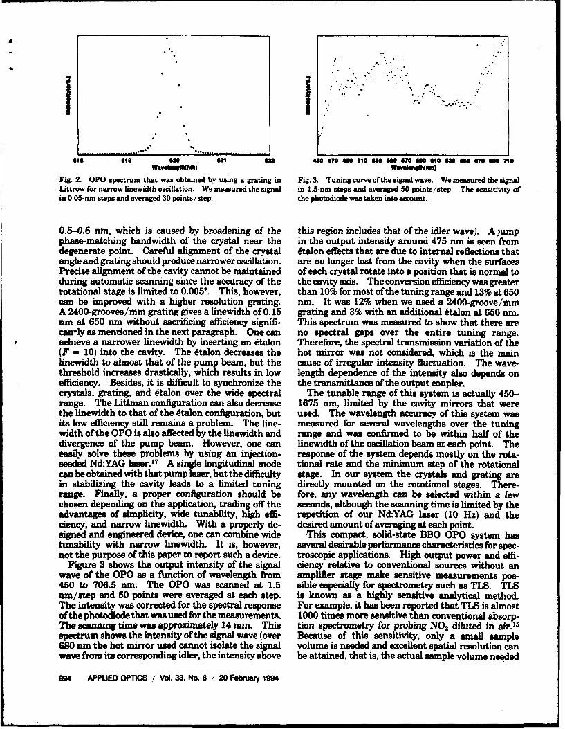
.. . ..
• 1". ...." "'.S.•
616 6 620 6 62 40 470 460 110 6 M M M Me 6 66 MM 70OWa"W (nm) WOvsMsinm)
Fig. 2. OPO spectrum that was obtained by using a grating in Fig. 3. Tuning curve of the signal wave. We measured the signalLittrow for narrow linewidth oscillation. We measured the signal in 1.5-nm steps and averaged 50 points/step. The sensitivity ofin 0.05-nm steps and averaged 30 points/step, the photodiode was taken into account.
0.5-0.6 rm, which is caused by broadening of the this region includes that of the idler wave). A jumpphase-matching bandwidth of the crystal near the in the output intensity around 475 nm is seen fromdegenerate point. Careful alignment of the crystal 6talon effects that are due to internal reflections thatangle and grating should produce narrower oscillation, are no longer lost from the cavity when the surfacesPrecise alignment of the cavity cannot be maintained of each crystal rotate into a position that is normal toduring automatic scanning since the accuracy of the the cavity axis. The conversion efficiency was greaterrotational stage is limited to 0.005*. This, however, than 10% for most of the tuning range and 13% at 650can be improved with a higher resolution grating. nmn. It was 12% when we used a 2400-groove/mmA 2400-grooves/mm grating gives a linewidth of 0.15 grating and 3% with an additional dtalon at 650 nm.nm at 650 rm without sacrificing efficiency signifi- This spectrum was measured to show that there arecantly as mentioned in the next paragraph. One can no spectral gaps over the entire tuning range.
* achieve a narrower linewidth by inserting an 6talon Therefore, the spectral transmission variation of the(F = 10) into the cavity. The dtalon decreases the hot mirror was not considered, which is the mainlinewidth to almost that of the pump beam, but the cause of irregular intensity fluctuation. The wave-threshold increases drastically, which results in low length dependence of the intensity also depends onefficiency. Besides, it is difficult to synchronize the the transmittance of the output coupler.crystals, grating, and dtalon over the wide spectral The tunable range of this system is actually 450-range. The Littman configuration can also decrease 1675 mm, limited by the cavity mirrors that werethe linewidth to that of the dtalon configuration, but used. The wavelength accuracy of this system wasits low efficiency still remains a problem. The line- measured for several wavelengths over the tuningwidth of the OPO is also affected by the linewidth and range and was confirmed to be within half of thedivergence of the pump beam. However, one can linewidth of the oscillation beam at each point. Theeasily solve these problems by using an injection- response of the system depends mostly on the rota-seeded Nd:YAG laser.17 A single longitudinal mode tional rate and the minimum step of the rotationalcan be obtained with that pump laser, but the difficulty stage. In our system the crystals and grating arein stabilizing the cavity leads to a limited tuning directly mounted on the rotational stages. There-range. Finally, a proper configuration should be fore, any wavelength can be selected within a fewchosen depending on the application, trading off the seconds, although the scanning time is limited by theadvantages of simplicity, wide tunability, high effi- repetition of our Nd:YAG laser (10 Hz) and theciency, and narrow linewidth. With a properly de- desired amount of averaging at each point.signed and engineered device, one can combine wide This compact, solid-state BBO OPO system hastunability with narrow linewidth. It is, however, several desirable performance characteristics for spec-not the purpose of this paper to report such a device. troscopic applications. High output power and effi-
Figure 3 shows the output intensity of the signal ciency relative to conventional sources without anwave of the OPO as a function of wavelength from amplifier stage make sensitive measurements pos-450 to 706.5 rum. The OPO was scanned at 1.5 sible especially, for spectrometry such as TLS. TLSnm/step and 50 points were averaged at each step. is known as a highly sensitive analytical method.The intensity was corrected for the spectral response For example, it has been reported that TLS is almostof the photodiode that was used for the measurements. 1000 times more sensitive than conventional absorp-The scanning time was approximately 14 min. This tion spectrometry for probing NO2 diluted in air.'5spectrum shows the intensity of the signal wave (over Because of this sensitivity, only a small sample680 nm the hot mirror used cannot isolate the signal volume is needed and excellent spatial resolution canwave from its corresponding idler, the intensity above be attained, that is, the actual sample volume needed
994 APPUED OPTICS .' Vol. 33, No. 6 ' 20 February 1994

for the thermal lens signal is defined only by the beamcross section and the confocal distance of the focusinglens. In our demonstration the OPO beam was £
tightly focused, which led to a short confocal distance(<1 mm). This is not claimed to be optimum butwas good enough to allow the use of a 1-cm flow cell. j ,The thermal lens signal was strong enough for ademonstration that allowed us to obtain a spectrum Vcomparable with that measured with a 1.2-1.3% e-sample with a 7.5-cm cell.'s Furthermore, the BBOOPO TLS system makes a fingerprinting assignment(which has been of interest but unachievable withconventional dye lasers) feasible because of its broad oo 620 640 66 6otunability. These characteristics are quite suitable WuMelaiwJfor a remote-sensing device. In Subsection 3.B we Fig. 5. Thermal lens spectrum (T.L.S.) of NO 2 from 600 to 680discuss more about the measurement of the NO2 nm. We measured the signal in 0.3-nm steps and averaged 100thermal lens spectrum. points/step.
B. Thermal Lens Spectrum of NO2
Figure 4 shows the thermal lens spectrum of NO2 spectrum cannot be resolved at this resolution. Asfrom 450 to 690 nm. Each peak corresponds well the excitation beam is tuned toward the wavelengthwith previously reported spectra.'8 In this experi- of the He-Ne laser, it can spuriously give a positivement the idler was not isolated. However, absorp- signal at the photomultiplier tube. However, sincetion of the idler wavelength by the sample was small the OPO beam is polarized linearly and has a fast riseand so could be neglected.19 Since the intensity of time, it can easily be separated by using a polarizerthe thermal lens signal is proportional to the laser and by changing the gate position of the boxcar.power, intensity variations over the tuning range willaffect the amplitude of the spectral peaks. This is 4 Conclusionsthe reason the peaks under 470 nm are relatively In this study we have reported on a computerizedsmall. During a scan over such a wide spectral BBO OPO system with a narrow linewidth oscillationrange, dispersion of the focusing lens and the beam of 0.2-0.6 nm over its visible tuning range. Wesplitter might have influenced the signal intensity, demonstrated its performance by measuring the ther-In this experiment, however, we estimated the confo- mal lens spectrum of NO2. The tunability of ourcal distance to be less than 1 mm. Over the spectral system, 450-1675 nmi, is much broader than that ofrange, the focal point and the focal length changed by commercially available dye laser systems that requireless than 0.1 mm and a few millimeters, respectively, dye changes to achieve a wide spectral region. OurSince we employed the direct incidence method, these system also tunes more quickly and easily over itsfactors should have had no significant effect on the whole tuning range. The OPO system is completelyspectrum. solid state (exccept for the YAG laser pumped by a
Figure 5 shows the spectrum of the same sample water-cooled flash lamp) and consists of commerciallybetween 600 and 680 nm, reproducing exactly the available components. This makes it a very practicalknown spectrum of this molecule.18 Because NO2 tunable laser system. The system succeeded in mea-shows a complicated spectrum,'9 finer details of the suring the entire visible thermal lens spectrum of
NO2 in a single scan with adequate resolution toresolve the important peaks, thus demonstratingexcellent pointing stability and wide tunability. Itcan be optimized with the appropriate optics toproduce tunable ultraviolet, visible, and infrared ra-diation. Therefore, the BBO OPO has significantIpractical advantages as a laser source in many spectro-scopic and spectrometric applications.I This work has been supported by the U.S. NavalResearch Laboratory, the National Science Founda-tion, and the Japan Society for the Promotion ofScience. S. Kawasaki acknowledges the Japan Soci-ety for the Promotion of Science Fellow for ResearchAbroad.
46 470 4010 Ila 0 n1o 570 no 610 62 o0 670 6owe111(fO) References
Fig. 4. Thermal lens spectrum (T.L.S.) of NO2 from 450 to 690 1. N. M. Kroll, "Parametric amplification in spatially extendednm. We measured the signal in 0.5-nm steps and averaged 50 media and application to the design of tunable oscillators atpoints/step. The sample was diluted in dry air to0.5%. optical frequencies," Phys. Rev. 127, 1207-1211 (1962); S. A.
20 February 1994 / Vol. 33, No. 6 / APPLIED OPTICS 995
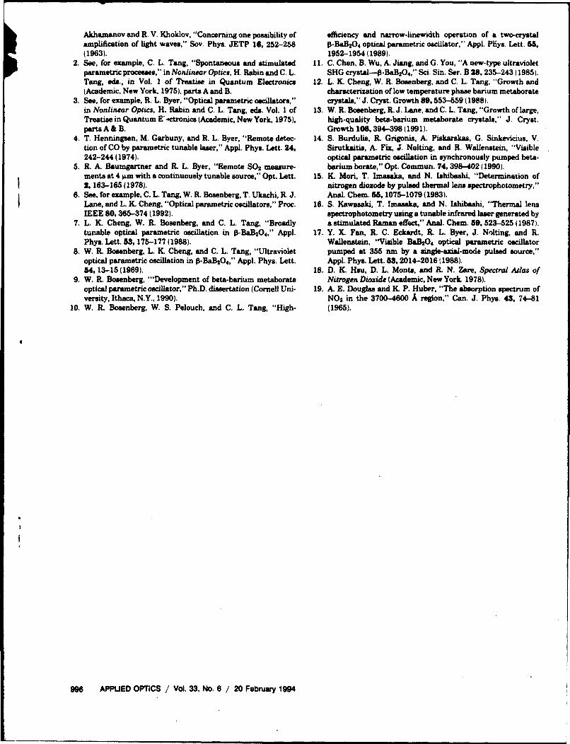
Akhamanov and R. V. Khoklov, "Concerning one possibility of efficiency and narrow-linewidth operation of a two-crystalamplification of light waves," Soy. Phys. JETP 16, 252-258 O-BaB20 4 optical parametric oscillator," Appl. Pljys. Lett. 55,(1963). 1952-1954(1989).
2. See, for example, C. L. Tang, "Spontaneous and stimulated 11. C. Chen, B. Wu, A. Jiang, and G. You, "A new-type ultravioletparametric processes," in Nonlinear Optics, H. Rabin and C. L. SHG crystal-o-BaB20 4," Sci. Sin. Ser. B 28. 235-243 (1985).Tang, eds., in Vol. I of Treatise in Quantum Electronics 12. L. K. Cheng, W. R. Bosenberg, and C. L. Tang, "Growth and(Academic, New York, 1975), parts A and B. charactenzation of low temperature phase barium metaborate
3. See, for example, R. L. Byer, "Optical parametric oscillators," crystals," J. Cryst. Growth 89,553-559 (1988).in Nonlinear Optics, H. Rabin and C. L. Tang, eds. Vol. I of 13. W. R. Boeenberg, R. J. Lane, and C. L. Tang, "Growth of large,Treatise in Quantum E'.ctronics (Academic, New York. 1975), high.quality beta-barium metaborate crystals," J. Cryst.parts A & B. Growth 106, 394-398 (1991).
4. T. Henningsen, M. Garbuny, and R. L. Byer, "Remote detec- 14. S. Burdulis, R. Grigonis, A. Piskarskas, G. Sinkevicius, V.tion of CO by parametric tunable laser," Appl. Phys. Lett. 24, Sirutkaitis, A. Fix, J. Nolting, and R. Wallenstein, "Visible242-244 (1974). optical parametric oscillation in synchronously pumped beta-
5. R. A. Baumgartner and R. L. Byer, "Remote S0 2 measure- barium borate," Opt. Commun. 74, 398-402 (1990).ments at 4 ýLm with a continuously tunable source," Opt. Lett. 15. K Mori, T. Imsaka, and N. Ishibashi, "Determination of2, 163-165(1978). nitrogen dioxode by pulsed thermal lens spectrophotometry,"
6. See, for example, C. L. Tang, W. R. Bosenberg, T. Ukachi, R. J. Anal. Chem. 65, 1075-1079 (1983).Lane, and L. K. Cheng, "Optical parametric oscillators," Proc. 16. S. Kawasaki, T. Imseaka, and N. Ishibashi, "Thermal lensIEEE 80, 365-374 (1992). spectrophotometry using a tunable infrared laser generated by
7. L. K. Cheng, W. R. Bosenberg, and C. L. Tang, "Broadly a stimulated Raman effect," Anal. Chem. 59, 523-525 (1987).tunable optical parametric oscillation in 1-BaB2O4," Appl. 17. Y. X. Fan, R. C. Eckardt, R. L. Byer, J. Nolting, and R.Phys. Lett. 53, 175-177 (1988). Wallenstein, "Visible BaB2O4 optical parametric oscillator
8. W. R. Bosenberg, L. K Cheng, and C. L. Tang, "Ultraviolet pumped at 355 um by a single-axial-mode pulsed source,"optical parametric oscillation in 1-BaB20 4," Appl. Phys. Lett. Appl. Phys. Lett. 53, 2014-2016 (1988).54,13-15(1989). 18. D. K. Hsu, D. L. Monts, and R. N. Zare, Spectral Atlas of
9. W. R. Bosenberg, "'Development of beta-barium metaborate Nitrogen Dioxide (Academic, New York. 1978).optical parametric oscillator," Ph.D. dissertation (Cornell Uni- 19. A. E. Douglas and K. P. Huber, "The absorption spectrum ofversity, Ithaca, N.Y., 1990). NO 2 in the 3700-4600 A region," Can. J. Phys. 43, 74-81
10. W. R. Bosenberg, W. S. Pelouch, and C. L. Tang, "High- (1965).
996 APPUED OPTICS / Vol. 33, No. 6 / 20 February 1994


![Best Avai~lable Copy · electroscopes and electrometers [9, 70, 74], the arm balance by two fine vertical fibers in low pressure manometers [78], in radia- as a replacement for the](https://static.documents.pub/doc/80x56/606b609594a43b3ad670fcb4/best-available-copy-electroscopes-and-electrometers-9-70-74-the-arm-balance.jpg)


