BIO-COMPOSITE MATERIAL APPLICATIONS TO
MUSICAL INSTRUMENTS
By
Steven Phillips
Structures and Composite Materials Laboratory
Department of Mechanical Engineering
McGill University, Montreal
A Thesis Submitted to the Faculty of Graduate Studies and Research in Partial
Fulfillment of the Requirements of the Degree of Master of Engineering
© Steven Phillips 2009
ii
ABSTRACT
Bio-composite materials suitable for replacing wood for use in musical
instruments were developed. The mechanical properties of Sitka spruce, the most
widely used wood species for this application, were taken as a benchmark when
developing the new materials. The materials were characterized by static and
dynamic methods to determine the dynamic Young's modulus, shear modulus,
internal friction and static mechanical properties. Based on the material
characterization, a hand layup process with a two-part closed mould and internal
pressure bladder was developed and a total of six prototype ukuleles were
manufactured. The results show that the bio-composite material can meet all the
necessary criteria for a soundboard material and that an efficient manufacturing
process can be developed for producing composite musical instruments.
KEYWORDS: Natural fibres; dynamic mechanical properties; composite
musical instruments; vibrations; acoustics
iii
RÉSUMÉ
Des matériaux bio-composites dans le but de remplacer le bois pour les
instruments de musique ont été développés. Les propriétés mécaniques de
l'épinette de Sitka, une espèce de bois couramment utilisée pour cette application,
ont été utilisées comme référence dans l'élaboration de nouveaux matériaux. Ces
derniers ont été caractérisés par des tests mécaniques statiques et dynamiques afin
de déterminer le module d'élasticité, le module de cisaillement, la friction interne
et les propriétés mécaniques statiques. Les résultats de caractérisation ont permis
de développer un procédé de fabrication avec un moule en deux parties et un sac
pressurisé. Six prototypes de ukulélés ont été fabriqués. Les résultats montrent
que le bio-composite peut répondre aux critères nécessaires pour un matériel de
table d'harmonie et qu'un processus de fabrication efficace peut être développé
pour produire des instruments de musique en matériaux composites.
MOTS CLÉS: Fibres naturelles; propriétés mécaniques dynamiques; instruments
de musique en composites, vibrations, acoustique
iv
ACKNOWLEDGEMENTS
I would first like to acknowledge my supervisor, Professor Larry Lessard, for
giving me the opportunity to pursue this research and for his support throughout
the project as well as for being an invaluable friend and mentor. I am also
grateful for the help of the former lab engineer of the Structure and Composite
Materials Laboratory at McGill University, Jonathan Laliberté, who passed on
his experience in designing composite parts and instructed me on how to operate
various lab equipment. I would further like to thank the following people who
assisted me at various stages throughout the project:
Mechanical testing – Professor Luc Mongeau from McGill University
who provided access to the dynamic testing equipment as well as advice
on modal testing. Kyle Goyette and Melanie Tetrault-Friend who
assisted with the static mechanical testing.
Machining – Gary Savard, Tony Micozzi, Andreas Hofmann and
Raymond Lemay from the machine tool laboratories whose advice saved
me much time.
Manufacturing – Delara Sadigh-Mostoufi, Meysam Rahmat and
Ronnie Lawand who assisted in manufacturing the prototypes.
Listening tests – The twenty volunteers who participated and also Harold
Kilanski for his help arranging the tests.
The financial support and lab access provided by the Center for
Interdisciplinary Research in Music Media Technology (CIRMMT) is also
acknowledged.
Finally, I would like to thank my loving family who taught me the value of
education and also encouraged me to pursue this research. I am very grateful for
the support they have provided throughout this project.
v
TABLE OF CONTENTS
ABSTRACT ........................................................................................................ ii
RÉSUMÉ ........................................................................................................... iii
ACKNOWLEDGEMENTS ................................................................................ iv
1. INTRODUCTION ...................................................................................... 1
1.1 Introduction to bio-composites ......................................................... 2
1.2 Overview of the guitar ...................................................................... 3
1.3 Motivation ........................................................................................ 5
1.4 Objectives ........................................................................................ 5
1.5 Thesis Organization .......................................................................... 5
2. LITERATURE REVIEW .......................................................................... 7
2.1 Soundboard criteria .......................................................................... 7
2.2 Use of non-traditional materials ...................................................... 10
2.2.1 Advanced composite materials .................................................... 10
2.2.2 Other non-traditional materials .................................................. 11
2.3 Musical acoustics ........................................................................... 12
2.3.1 Air cavity .................................................................................... 12
2.3.2 Strings ........................................................................................ 13
2.3.3 Impedance matching ................................................................... 13
3. MATERIAL CHARACTERIZATION ................................................... 15
3.1 Material selection ........................................................................... 15
3.1.1 Fibre .......................................................................................... 16
3.1.2 Matrix ........................................................................................ 18
3.1.3 Core ........................................................................................... 18
3.2 Sample preparation ......................................................................... 19
3.2.1 Prepreg ...................................................................................... 19
3.2.2 Dry fabric ................................................................................... 20
3.2.3 Specimen cutting......................................................................... 21
3.3 Static testing ................................................................................... 22
3.3.1 Tensile testing ............................................................................. 22
vi
3.3.2 Compression testing ................................................................... 27
3.3.3 Shear Testing .............................................................................. 28
3.4 Dynamic testing ............................................................................. 30
3.5 Void content ................................................................................... 35
3.6 Results comparison......................................................................... 36
3.6.1 Bending stiffness ......................................................................... 37
3.6.2 Areal density............................................................................... 37
3.6.3 Internal friction .......................................................................... 38
3.6.4 Degree of anisotropy .................................................................. 39
3.7 Summary ........................................................................................ 40
4. PROTOTYPE DESIGN ........................................................................... 41
4.1 Computer model ............................................................................. 41
4.2 Finite element modelling ................................................................ 44
4.2.1 Meshing ...................................................................................... 44
4.2.2 Structural analysis ...................................................................... 45
4.2.3 Modal analysis ........................................................................... 47
5. MOULD DESIGN .................................................................................... 49
5.1 Computer model ............................................................................. 49
5.2 Machining and finishing ................................................................. 52
5.3 Pressure bladder ............................................................................. 54
5.3.1 Latex bladder ............................................................................. 54
5.3.2 Silicone bladder .......................................................................... 56
6. MANUFACTURING ............................................................................... 58
6.1 Preforms ......................................................................................... 58
6.1.1 Soundboard ................................................................................ 59
6.1.2 Back Plate .................................................................................. 59
6.1.3 Sides ........................................................................................... 60
6.1.4 Neck and headstock .................................................................... 60
6.1.5 Fingerboard ............................................................................... 61
6.2 Cure cycle ...................................................................................... 62
vii
6.2.1 Temperature lag ......................................................................... 63
6.3 Manufacturing process development ............................................... 64
6.4 Recurring defects............................................................................ 66
6.4.1 Fibre bridging ............................................................................ 66
6.4.2 Resin rich regions ....................................................................... 67
7. POST MACHINING ................................................................................ 68
7.1 Tuning machines ............................................................................ 68
7.2 Sound hole ..................................................................................... 69
7.3 Fret installation............................................................................... 70
7.4 Bridge and nut ................................................................................ 71
7.5 Finishing ........................................................................................ 72
8. FINAL EVALUATION ........................................................................... 73
8.1 Listening tests ................................................................................ 73
9. CONCLUSIONS ...................................................................................... 76
9.1 Major contributions ........................................................................ 76
9.2 Future work .................................................................................... 77
APPENDICES ................................................................................................... 78
References ......................................................................................................... 83
viii
LIST OF FIGURES
Figure 1-1: Yo-Yo Ma playing a carbon fibre cello [3] ........................................ 1
Figure 1-2: Flax based sporting goods.................................................................. 3
Figure 1-3: Parts of the guitar .............................................................................. 4
Figure 3-1: Cell wall microstructure of wood ..................................................... 15
Figure 3-2: Common flax (Linum usitatissimum) ............................................... 17
Figure 3-3: Flax materials used in this study ...................................................... 17
Figure 3-4: Hot press setup for manufacturing testing coupons .......................... 20
Figure 3-5: Vacuum-assisted-resin-transfer-moulding setup ............................... 20
Figure 3-6: Dynamic testing specimen geometry ............................................... 22
Figure 3-7: Tensile testing setup ........................................................................ 23
Figure 3-8: Average stress-strain curves from tensile testing .............................. 24
Figure 3-9: Young's modulus versus fibre volume fraction ................................. 25
Figure 3-10: Specific tensile properties of studied materials ............................... 26
Figure 3-11: Failure modes observed during compression testing....................... 27
Figure 3-12: Specific compressive strength of studied materials ........................ 28
Figure 3-13: Shear testing setup ......................................................................... 29
Figure 3-14: Specific in-plane shear properties of studied materials ................... 30
Figure 3-15: Dynamic test setup with laser Doppler velocimeter ........................ 31
Figure 3-16: Sample response from dynamic testing .......................................... 34
Figure 3-17: Cross sections of flax samples showing void content ..................... 36
Figure 3-18: Young's modulus in x-direction of soundboard materials ............... 37
Figure 3-19: Areal densities of soundboards ...................................................... 38
Figure 3-20: Internal friction in x-direction of soundboard materials .................. 39
Figure 3-21: Degree of anisotropy of soundboard materials ............................... 39
Figure 4-1: Rendered image of prototype computer model ................................. 41
Figure 4-2: Draft angle and curvature details for prototype design ..................... 43
Figure 4-3: Illustration of neck joint................................................................... 44
Figure 4-4: Finite element model of prototype soundboard ................................ 45
Figure 4-5: Maximum-stress failure criteria for prototype under string tension .. 46
ix
Figure 4-6: Fundamental resonant frequencies of soundboard and back plate ..... 48
Figure 5-1: Computer assembly of two-part closed mould with inserts ............... 50
Figure 5-2: Illustration of knife edge tool included in mould design ................... 50
Figure 5-3: Placement of O-rings in prototype mould......................................... 51
Figure 5-4: Pressure application inserts in mould design .................................... 51
Figure 5-5: Internal pressure bladder sealing device ........................................... 52
Figure 5-6: CNC machining of prototype mould ................................................ 53
Figure 5-7: “Scallops” left by ball end mills during CNC machining.................. 53
Figure 5-8: Two-part mould after sanding and polishing .................................... 54
Figure 5-9: Polyurethane dipping tools used for making custom latex bladders .. 55
Figure 5-10: Final design of polyurethane dipping tool ...................................... 56
Figure 5-11: Silicone bladder inside of the mould .............................................. 57
Figure 6-1: Details of preform design for prototype ukulele ............................... 58
Figure 6-2: Soundboard preform design ............................................................. 59
Figure 6-3: Back plate preform design ............................................................... 59
Figure 6-4: Side preform design ......................................................................... 60
Figure 6-5: Neck and headstock preform design................................................. 61
Figure 6-6: Layup designs for fingerboard ......................................................... 61
Figure 6-7: Mould insert developed for fingerboard preforms ............................ 62
Figure 6-8: Thermocouple setup for mould heating study................................... 63
Figure 6-9: Thermal behavior of two-part closed mould and convection oven .... 63
Figure 6-10: Cure cycle from mould heating study............................................. 64
Figure 6-11: Bonding tabs and bracing installation ............................................ 65
Figure 6-12: Recurring defects on prototypes ..................................................... 66
Figure 6-13: Illustration of fibre bridging ........................................................... 67
Figure 7-1: Installation of tuning machines ........................................................ 69
Figure 7-2: Post-machining jig for trimming sound hole .................................... 70
Figure 7-3: Installation of fret wire .................................................................... 70
Figure 7-4: Template used for attaching the bridge ............................................ 71
Figure 7-5: Completed flax prototype ................................................................ 72
Figure 8-1: Ukuleles that were subjected to listening tests .................................. 74
x
Figure 8-2: Results from blind listening tests ..................................................... 75
LIST OF TABLES
Table 3-1: Summary of sample processing methods ........................................... 19
Table 3-2: Static testing specimen dimensions ................................................... 21
Table 3-3: Mechanical properties obtained from tensile testing .......................... 24
Table 3-4: Compressive strengths of flax prepregs ............................................. 28
Table 3-5: Shear properties obtained from three-rail test fixture ......................... 29
Table 3-6: Dynamic testing results for flax sandwich structures and spruce ....... 35
Table 4-1: Prototype and classical guitar dimensions ......................................... 42
Table 8-1: Summary of ukuleles that were subjected to the listening tests .......... 74
LIST OF EQUATIONS
Equation 2-1: Schelleng stiffness criteria ............................................................. 7
Equation 2-2: Schelleng areal density criteria ...................................................... 7
Equation 2-3: Ono soundboard quality criteria ..................................................... 9
Equation 2-4: Resonant frequency of neckless Helmholtz resonator ................... 12
Equation 2-5: Resonant frequency of vibrating string ......................................... 13
Equation 2-6: String impedance ......................................................................... 14
Equation 2-7: Soundboard impedance ................................................................ 14
Equation 3-1: Fibre volume fraction .................................................................. 25
Equation 3-2: Dynamic Young's modulus .......................................................... 33
Equation 3-3: Dynamic shear modulus ............................................................... 33
Equation 3-4: Quality factor............................................................................... 33
xi
LIST OF SYMBOLS
Symbol Description
E Young’s modulus
Ex Longitudinal Young’s modulus
Ey Transverse Young’s modulus
Es Longitudinal shear modulus
h Thickness
ρ Density
Qx-1
Longitudinal internal friction
Qy-1
Transverse internal friction
γ Areal density
c Speed of sound
V Volume
a Radius of sound hole
L Length
T String tension
µ String mass per unit length
m Mass
ff Resonant frequency in flexure
ft Resonant frequency in torsion
b Width
A, B Dynamic shear modulus correction factors
ωr Resonant angular frequency
ωa, ωb Angular frequencies of half-power points
1. Introduction
In relatively recent times, the development of composite materials has led to
superior performance for many applications. An often overlooked application that
has benefited greatly from their development is musical instruments. The
inherent orthotropic behavior of composite materials makes them a suitable
replacement for wood that is traditionally used in this application [1]. For this
reason, composite guitar and violin soundboards were developed as early as 1975
[1]. Several composite musical instruments can now be found in the marketplace
ranging from cellos to flutes and these instruments have been a more common
sight in the hands of professional musicians. Yo-Yo Ma now chooses to play a
carbon fibre cello at some of his live performances due to its greater stability
(Figure 1-1). For this reason, he planned to play one at the inauguration of
President Barack Obama, however, he did not out of concern he might distract
viewers with its appearance [2]. This suggests that a composite material with a
closer resemblance to wood may be desirable for professional musicians required
to perform in formal settings.
Figure 1-1: Yo-Yo Ma playing a carbon fibre cello [3]
2
In recent studies, there are several reasons why composite materials have been
used to replace wood in musical instruments:
Better resistance to environmental effects - Musicians often have to make
costly repairs due to wood cracking from humidity and temperature
changes. Composite materials are very stable to environmental changes
and are a better investment for long term use.
Less variability - Selection of wood species and sections that are free of
defects has traditionally relied upon the skills of a luthier. Composite
materials offer the possibility of producing consistent musical instruments
without the worry of wood defects that can be detrimental to the sound.
Lower production time – Composite materials offer greater possibilities in
design that allow the manufacturer to reduce production time and cost by
reducing the number of parts an instrument is built from.
Endangered wood species – Some wood species that were commonly
used in musical instruments are now in limited supply. Most notably,
Brazilian rosewood which was the most widely used species for the back
and sides of stringed instruments, is now listed in the Convention on
International Trade in Endangered Species of Wild Flora and Fauna
(CITES) database and its use is tightly controlled [4]. Composite
materials offer the possibility of mimicking the behaviour of unique wood
species such as Brazilian rosewood.
1.1 Introduction to bio-composites
Bio-composites are composite materials that are reinforced with natural fibres
derived from plant, animal and mineral sources. For a material to be classified as
a bio-composite, any type of matrix can be used including conventional petroleum
derived polymers [5]. If a sustainable matrix is used in conjunction with natural
3
fibres, the final material is then classified as a “green” composite [6]. Since
natural fibres are sustainable, bio-composites will likely be less costly than their
carbon fibre counterparts in the near future.
Bio-composite materials have gained recent attention due to growing
environmental concerns. They are currently primarily used as body paneling in
the automotive industry [7] but some sporting goods and other applications have
also been developed. A flax based bicycle and tennis racket that are currently
available on the market are shown in Figure 1-2.
(a)
(b)
Figure 1-2: Flax based sporting goods (a) Museeuw MF-5 bicycle [8] (b) Artengo 820
tennis racket [9]
1.2 Overview of the guitar
Stringed musical instruments come in several forms and almost every country has
one that is a unique part of its cultural history. In the western world, the guitar is
one of the most commonly played and familiar sounding. The modern day guitar
has its origins from the sixteenth century Spanish Vihuela [10]. Guitars along
with most other stringed instruments operate in the same way. Sound is created
by an acoustic structure that is excited by strings under tension. The structure or
“body” of the instrument usually consists of two vibrating membranes connected
by sides, an acoustic cavity and a neck where the performer places their fingers.
These elements are coupled to the strings by means of a component called the
4
“bridge”. The strings do not produce much sound on their own, due to their small
area, but they transmit energy to the rest of the structure that is coupled with the
surrounding air. The primary parts of the guitar are shown in Figure 1-3.
Figure 1-3: Parts of the guitar [11]
Several stringed instruments are closely related to the guitar and are said to belong
to the guitar family of musical instruments [12]. The soprano ukulele is the
smallest instrument of this family and was selected as the prototype instrument for
this study since its structure is almost identical to the guitar and its small size
reduced tooling costs.
5
1.3 Motivation
The primary motivation of this research was to investigate if a high quality
stringed musical instrument could be made from bio-composites. Due to the
superior mechanical properties of carbon fibre, limited research has investigated
the use of other reinforcement fibres for this application. The inherent wood-like
characteristics of bio-composites make them seem like ideal candidates for
replacing wood. They would possibly solve the aesthetic problem and have closer
acoustic properties to wood since both are based on cellulose fibres. Another
motivation of this research was to reduce the production time and craftsmanship
that it currently takes to build a musical instrument by taking advantage of the
inherent benefits of composite materials.
1.4 Objectives
The objectives of this research were selected to both assess the feasibility of using
a bio-composite material as a soundboard and also to develop a manufacturing
process to produce low-cost musical instruments. The objectives were as follows:
1) Perform static and dynamic mechanical characterization on a flax/epoxy
bio-composite
2) Asses the feasibility of using bio-composites as the soundboard of a
stringed musical instrument
3) Develop a manufacturing process to produce low-cost stringed musical
instruments from composite materials
4) Compare a bio-composite stringed instrument to one of known high
quality made out of wood
1.5 Thesis Organization
To achieve the above objectives, the thesis was divided into the following
chapters. First, Chapter 2 is a literature review that describes previous research
that has been done in developing alternative materials for the soundboards of
stringed instruments. Chapter 2 also provides a brief overview of engineering
6
acoustics in the context of designing stringed musical instruments. Following the
literature review, Chapter 3 is a description of the studied materials as well as the
testing procedures that were used to characterize them. Chapter 4 and 5 discuss
the design of the prototype stringed instrument and the corresponding tooling.
Chapter 6 and 7 describe the manufacturing and post-machining processes
respectively that were developed to build the prototype ukuleles. Finally, Chapter
8 discusses the evaluation of the final prototypes.
7
2. Literature Review
To successfully develop a soundboard from bio-composites, it was required to
know which mechanical properties lead to a good soundboard and also which
non-traditional materials have been investigated in the past. Furthermore, in order
to build a prototype, it was required to gain a general knowledge of engineering
acoustics in the context of designing stringed instruments. As a result, the main
literature that was reviewed can be divided into three categories; soundboard
criteria, use of non-traditional materials and musical acoustics.
2.1 Soundboard criteria
The mechanical properties that lead to a good soundboard have been known in the
scientific community for over a half a century. The quality of stringed
instruments has been shown to strongly depend on the frequency response [13].
This frequency response in turn depends on the mechanical properties of the
material. Based on this assumption, criteria have been developed that govern the
use of non-traditional materials based on their mechanical properties. The first
work in this area was performed by John Schelleng [14]. He determined that for
the flexural behavior of two homogeneous plates to be the same, their stiffness per
unit length and density per unit area must be the same. This can be summarized
by the following two relationships.
Equation 2-1: Schelleng stiffness criteria
Equation 2-2: Schelleng areal density criteria
where Ei is the Young’s modulus, hi is the thickness and ρi is the density.
Subscripts 1 and 2 represent the two materials that have the same flexural
behaviour.
8
The criteria proposed by Schelleng imply that even if the same stiffness cannot be
achieved by a substitute material, the thickness can be altered so that the bending
stiffness remains the same. However, if the areal density criterion is exceeded in
doing so, the given material may not be a good substitute for wood. Schelleng
also demonstrated why Sitka spruce (picea sitchensis), the wood traditionally used
for violin and guitar soundboards, is superior for this purpose. Sitka spruce has a
very low density, high specific modulus and low internal friction. For this reason,
Sitka spruce is typically used as the benchmark when developing a substitute
material. The mechanical properties of Sitka spruce, along with other woods
commonly used in musical instruments are shown in Appendix A.
Haines et al later extended the work of Schelleng to account for the use of a non-
homogeneous material. Their criteria were derived from the flexural equations of
motion for a flat plate. The criteria were essentially the same as those proposed
by Schelleng with two additional criteria; high degree of anisotropy and low
internal friction. Low internal friction is desirable so that the sound from the
musical instrument does not die too rapidly. The importance of the degree of
anisotropy criteria was later demonstrated by Ono et al using the frequency
response functions of various plates. It was shown that plates with a large
variation of in-plane stiffnesses respond better to a wider range of frequencies
[15]. By contrast, isotropic plates only respond well to a limited range of
frequencies.
Hanies et al proposed the following quantitative values based on a typical 2.5 mm
thick spruce soundboard [1].
1. Ratio of x-direction to y-direction bending stiffnesses of at least 12
2. Ratio of x-direction bending stiffness to areal density of at least 12x106
(m/s)2
3. Areal density between 1.1 and 1.4 kg/m2
4. Logarithmic decrements in both in-plane directions generally increasing
with frequency
9
Haines et al determined that for a composite sandwich structure to satisfy these
criteria, a sufficiently high stiffness fibre must be used with a very low density
core material. If a core material is not used, the areal density limit would be
surpassed before the required bending stiffness was reached.
Although most research has focused on the properties in the x-direction (along-
the-grain or fibre direction), Ono et al investigated the importance of the y-
direction (across-the-grain or transverse direction) and shear properties. They
determined that the properties in the y-direction play an important role in the
materials frequency response [15]. Wood used for soundboards has an average
cellulose microfibril angle of 5 degrees which leads to some reinforcement in the
y-direction [16]. Therefore to accurately mimic the frequency behaviour of wood,
the properties in the y-direction must be taken into consideration. Ono et al also
demonstrated that the behavior in the high frequency range is strongly dependent
on the shear modulus of the material [16]. Laminates with only surface
reinforcement inherently have a lower shear modulus and lead to a variation in
high frequency behavior. The author’s address the manufacturing difficulties in
producing evenly distributed fibers without exceeding the low density of wood.
In general, researchers have agreed that materials with a low density, high specific
modulus and low internal friction in the x-direction are best for soundboards.
These three factors can be summarized the following criterion proposed by Ono et
al [17].
Equation 2-3: Ono soundboard quality criteria
where Qx-1
, Ex and γ are the internal friction, Young’s modulus and areal density
respectively.
10
2.2 Use of non-traditional materials
The work of Schelleng and others led to the development of several non-
traditional soundboard materials. Advanced composite materials account for the
majority of these new soundboard materials. As discussed above, composite
materials are a good replacement for wood due to their inherent orthotropic
properties and superior stability.
2.2.1 Advanced composite materials
The first composite soundboard was developed by Daniel Haines and Carleen
Hutchins in conjunction with C.F Martin Inc in 1975 [1]. This soundboard was a
sandwich panel using carbon fibre/epoxy as the outer skins and cardboard as the
core. They also considered using polystyrene and polypropylene as the core,
however, these materials failed to lead to the low damping of Sitka spruce. The
final sandwich structure met all of the Haines et al criteria.
A later study performed by McIntyre and Woodhouse created a sandwich
structure with comparable stiffness and lower damping than spruce [18]. This
sandwich panel used balsa wood as the core material. Lower internal friction was
obtained than the cardboard core sandwich panel in the Haines et al study. This
suggests balsa wood may be a good core material in conjunction with fibres that
have higher internal friction than carbon.
Significant work was also performed by Ono et al to develop a soundboard
substitute based on polyurethane foam reinforced with unidirectional carbon
fibres [16, 19, 20]. Several ply sequences were investigated based on the author’s
previous work on soundboard wood characterization. Their recognition of the
importance of the shear modulus led them to develop substitutes that had fibres
that were very well distributed [16]. Furthermore, their studies on the properties
of wood in the y-direction led them to reinforce some experimental laminates in
the y-direction [20]. They also experimented with sandwich panels reinforced
11
only at the outer skins. Of all the laminates that were tested, the surface
reinforced sandwich panels performed best in listening tests [20].
At the same time of this study, researchers in the United Kingdom were
attempting to develop a carbon fibre violin that exceeded the sound quality of a
wooded one [21]. During the course of that study, it was determined that using a
lightweight foam core in a sandwich structure led to the soundboard skins
vibrating independently. The final carbon fibre prototype did not exceed the
quality of a wooden violin but work was ongoing to improve the material.
2.2.2 Other non-traditional materials
Although carbon fibre based composite materials have dominated the non-
traditional materials that have been investigated, some other interesting materials
have been considered. A study conducted by Yano et al investigated the use of
Japanese cedar to create a laminated material suitable for instrument back plates
[22]. Back plates generally have lower specific mechanical properties and are
primarily selected for their appearance [23]. Japanese cedar has poor mechanical
properties and grows very quickly thus making it a better alternative to
endangered wood species like Brazilian rosewood. The final laminated material
had very similar dynamic properties to Brazilian rosewood.
Balsa wood was also recently used to create a violin soundboard based on the
Schelleng scaling criteria by Waltham [24]. The prototype violin demonstrated a
very similar frequency response to one built from Spruce thus validating the
scaling criteria. There was however a mismatch in internal friction and the balsa
violin had a higher volume output. For this reason the final instrument was
deemed not to be acceptable for a professional musician.
An extensive study was also performed on the possible use of bamboo grass fibre
in a variety of musical instruments [25]. Bamboo was found to be suitable for
instruments where wood species with a high density and low internal friction are
12
typically used, however, it was found to be not acceptable for soundboards where
a very low density is required.
2.3 Musical acoustics
In order to successfully design a stringed instrument a general knowledge of
musical acoustics is necessary. Stringed instruments can be seen as coupled
vibrating systems where all elements must be understood in order to produce a
working instrument. In this study, focus will be specifically on the structure of
the guitar and closely related instruments. When the strings of the guitar are
plucked or struck, they transfer energy to the bridge and soundboard which in turn
transfer energy to the sides, back plate and air cavity. At low frequencies, the
soundboard transfers energy to the back plate through the sides and air cavity. At
high frequencies the sound is radiated primarily by the soundboard and bridge
[10].
2.3.1 Air cavity
The air cavity is critical for the low frequency response of a stringed instrument.
It can be approximated as a neckless Helmholtz resonator with a large face. The
resonant frequency is given by [10]:
Equation 2-4: Resonant frequency of neckless Helmholtz resonator
where c is speed of sound, a is the radius of sound hole, V is the volume of air
cavity and f is the resonant frequency.
The volume of the air cavity and radius of the sound hole are usually selected so
that this frequency corresponds to one of the low open string notes. For the guitar
it is typically around 98 Hz (G note) and for the soprano ukulele it is usually
around 260 Hz (C note) [12], however, in practice it is always placed slightly
13
below these frequencies as to not affect the volume balance of the individual notes
[12].
2.3.2 Strings
The strings are the primary interface between the performer and the musical
instrument. Traditionally, strings were made from sheep’s gut however modern
strings are usually made from nylon or steel. The frequency at which a string
vibrates is a function of its length, mass and tension. This frequency is given by:
Equation 2-5: Resonant frequency of vibrating string
where T is the string tension, L is the length of the string, µ is the mass per unit
length of the string and f is the resonant frequency.
While performing a musical piece, the frequency of a string is changed by altering
its length. Metal inserts known as “frets” are positioned so that when the string is
pushed against the fingerboard, it gains a new effective length and the desired
frequency is produced. The spacing of the frets is based on the musical scale that
the instrument is designed for and there are several types of musical scales all
over the world. In western music, a scale known as the equal temperament scale
has been historically used. The equal temperament scale divides an octave into 12
intervals where each note is times higher in frequency than the previous note
[26]. Two adjacent notes are said to be a “semitone” apart while two notes that
are separated by one note are said to be a “tone” apart.
2.3.3 Impedance matching
Another important concept in designing a stringed instrument is impedance
matching. For a wave to efficiently travel from one medium to another, the
impedances of both materials must be similar [27]. In the context of a stringed
14
instrument, the ratio of the string and soundboard impedances is critical. The
string impedance and soundboard impedance are given by the following equations
[27]:
Equation 2-6: String impedance
Equation 2-7: Soundboard impedance
where µ is the mass per unit length of the string, T is the string tension, E is the x-
direction stiffness and ρ is the density.
Unfortunately, it is not so straight forward as to simply match the impedances of
the strings and soundboard. If the impedances match perfectly, all of the energy
will be transmitted too quickly and the sound will die out rapidly. On the other
hand, if there is a large increase or decrease in impedance, the vibration will be
completely reflected and little sound will be produced. As a result, a balance
must be achieved so that enough of the energy is transmitted to the soundboard
while enough is retained in the string so that it remains vibrating for a sufficient
amount of time. This usually corresponds to a soundboard impedance of a few
thousand times greater than the string impedance [27].
15
3. Material Characterization
The first step in this project was to select appropriate fibres, matrix and core
materials in order to meet the requirements of a soundboard. After selecting
appropriate materials, a full static and dynamic characterization was performed to
compare the mechanical properties of the bio-composite with those of Sitka
spruce.
3.1 Material selection
Wood is a remarkable material due to its low density and high specific modulus
so it is no easy task to select another material to replace it. In general terms, wood
can be seen as a natural composite material, with cellulose fibres surrounded by a
lignin and hemicellulose matrix [28]. The low density of wood comes from its
high porosity, typically around 60% for spruce [29]. It would initially seem
possible to replace it with an equally porous bio-composite since these materials
are also normally based on cellulose fibres. This approach was not feasible since
the microstructure of wood is very complex and both microscopic and
macroscopic properties contribute to its high mechanical properties [28]. Even
though the layer angles in the cell wall of wood (Figure 3-1) are much the same as
a composite material ply sequence, it would be very difficult to recreate this
complex microstructure with existing manufacturing technology.
Figure 3-1: Cell wall microstructure of wood [30]
Middle Lamella
Primary Wall
Inner layer
Middle layer
Outer layer
16
Since it was not feasible to recreate the microstructure of wood, the approach of
developing a sandwich structure was taken. To meet the criteria necessary for a
soundboard it was critical to select an appropriate fibre, matrix and core material.
In the past, it would have been difficult to make an appropriate soundboard based
on natural fibres but with the quality of these fibres increasing it is now more
realistic. The following sections will discuss the fibres, matrix and core materials
that were considered in this study.
3.1.1 Fibre
After surveying several types of natural fibres, it was found that a category known
as bast fibres, which come from the stems of certain plants, had the highest
specific mechanical properties and thus the most potential as reinforcement. The
properties of bast fibres along with several other fibres are shown in Appendix B.
Of the various bast fibre producing plants, Ramie (Boehmeria nivea) produced the
stiffest and strongest fibres. For this reason, it seemed like an ideal candidate for
this application, however, its production was limited due to the high cost of
extracting its useful fibres as a result of its high gum content [31].
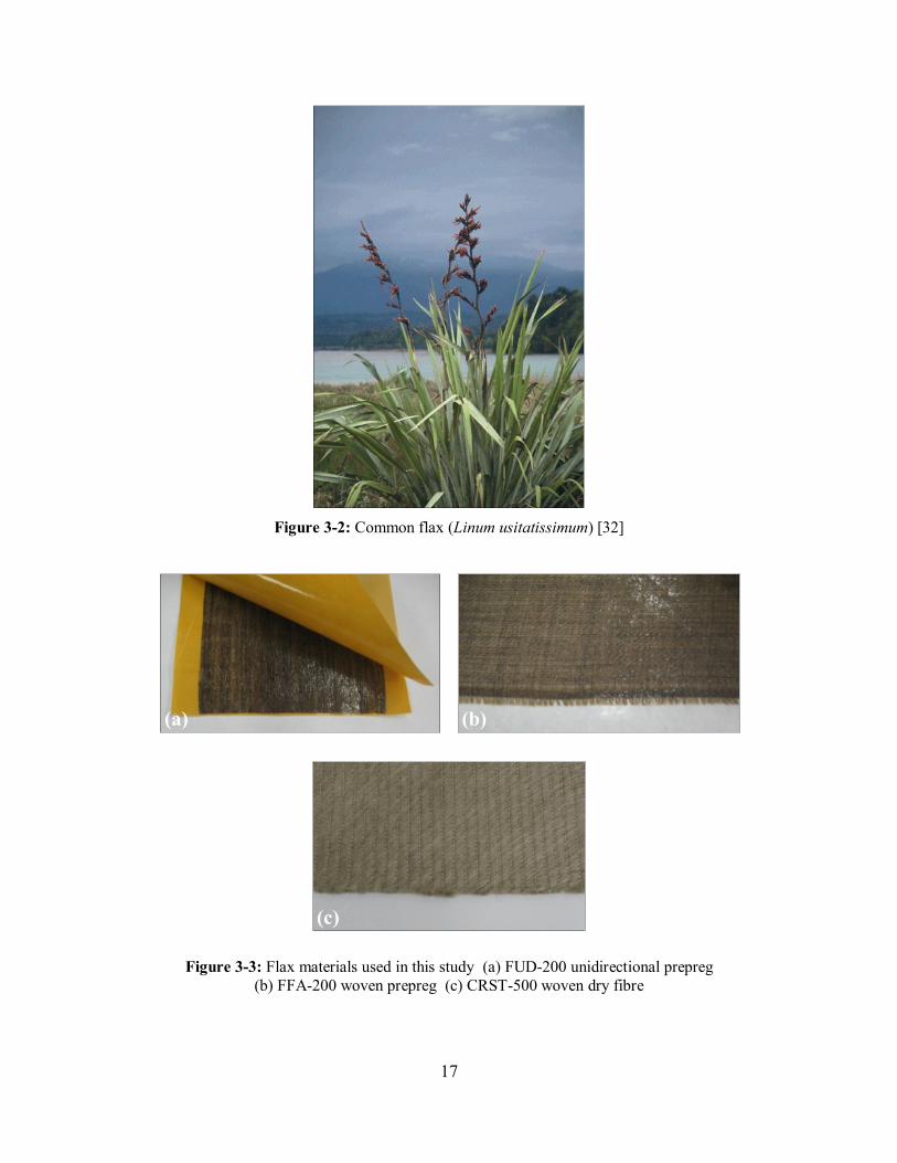
The bast fibre that was most readily available in useful form came from the flax
plant (Figure 3-2). Of the flax materials currently available, three were considered
in this study; unidirectional prepreg, woven prepreg and dry woven fibres (Figure
3-3). Flax fibres pre-impregnated with epoxy resin had the most potential based
on the supplier’s specifications, but due to their higher cost dry fibres were also
considered. The prepreg material was produced by Lineo NV of France and was
available in varying areal densities of fibres. The woven dry fibre was produced
by C.R.S.T also of France and was only available in one areal density (500 g/m2).
17
Figure 3-2: Common flax (Linum usitatissimum) [32]
Figure 3-3: Flax materials used in this study (a) FUD-200 unidirectional prepreg
(b) FFA-200 woven prepreg (c) CRST-500 woven dry fibre
(a) (b)
(c)
18
3.1.2 Matrix
Since the prepreg already had an epoxy resin system built in, a matrix only needed
to be selected for dry fibre. It was initially desired to select a sustainable matrix
to produce a composite that could be classified as “green”. Of the types of
sustainable resins, poly-L-lactic-acid (PLLA) was the most widely available but
had a low Young’s modulus of only 1.3 GPa [6]. Acrylated epoxidized soybean
oil (AESO) was also considered but had a stiffness less than half of conventional
epoxy [33]. Due to the difficulties in finding a sustainable matrix with adequate
mechanical properties, a conventional resin system was finally selected.
Selection of an appropriate resin system also depended on the manufacturing
process. In this study, a resin infusion process was used to make the dry fibre
samples which required a resin system with a viscosity below 500cPs and a fairly
long working time [34]. The vacuum-assisted-resin-transfer-moulding (VARTM)
system was chosen because it was a low-cost production method. A resin system
that was designed for this process was finally selected (Derakane Momentum 411-
350).
3.1.3 Core
To reach the required bending stiffness without exceeding the areal density limit
of the soundboard, it was necessary to select a very lightweight core material.
The core material also influenced the damping of the final laminate, so this was
another critical factor. A core with very low damping was desired to counteract
the inherent damping effects of the flax material. Based on the work of McIntyre
and Woodhouse, balsa wood was shown to lead to a laminate with excessively
low damping in conjunction with carbon fibres [18]. For this reason, balsa wood
was selected as the core material so that in combination with the flax fibres it
might lead to an acceptable damping factor. Typically, balsa wood used for core
material has the grain oriented normal to the fibre direction to aid with out-of-
plane compressive strength, however, for this study it was more desirable to have
the grain oriented in the fibre direction to give better mechanical properties for the
19
soundboard. Balsa strips typically used for model airplanes were selected for the
core. There were some initial concern as to how well the balsa would bond to the
flax prepreg but from initial samples it proved to bond very well.
3.2 Sample preparation
To investigate the effect of processing on the final material properties, samples
were made from three methods; vacuum bagging, hot press and vacuum-assisted-
resin-transfer-moulding (VARTM). A summary of the processing parameters is
given in Table 3-1 where the cure cycles were selected based on the
recommendations of the material specifications (Appendix C).
Table 3-1: Summary of sample processing methods
Process Material Pressure (atm) Cure cycle
Vacuum Bag - FUD200
- FFA200
1 30 min at 140°C
Hot Press - FUD200
- FFA200
7 30 min at 140°C
VARTM - C.R.S.T 500 1 24 hrs at ambient
Post cure: 2 hrs at 120°C
3.2.1 Prepreg
The flax prepreg samples were manufactured on a hot press (Figure 3-4a) and also
by vacuum bagging techniques. The amount of pressure applied on the hot press
was selected based on the maximum air line pressure that was used to pressurize
an internal pressure bladder during the manufacturing process of the prototype
ukuleles (7 atm). For both the vaccum bag and hot press samples, the cure cycle
was a 2°C/min heating ramp to 140 °C for 30 min with a cooling rate of
2.5°C/min. For this cure cycle, a glass transition temperature of between 135°C
and 145°C was expected based on the flax prepreg specifications (Appendix C).
The tool that was used to press the prepreg samples consisted of two nested
20
aluminum plates (Figure 3-4b). This mould was not sealed so resin was able to
bleed off during processing. For the vacuum bagging, a perforated release film
followed by a bleeder cloth was used on top of the flax prepreg.
Figure 3-4: Hot press setup for manufacturing testing coupons (a) hot press setup (b) tool plates for making coupons
3.2.2 Dry fabric
The dry woven flax fibre samples were prepared using a vacuum-assisted resin-
transfer-moulding (VARTM) setup (Figure 3-5). Derakane Momentum 411-350,
an epoxy vinyl ester resin suitable for VARTM, was selected as the matrix. The
resin was infused through the dry fibre using a vacuum pot at the outlet. The
infusion finished well before the resin gelled which implied that the viscosity of
the resin was low enough and that the permeability of the dry flax fibre was
sufficiently high.
Figure 3-5: Vacuum-assisted-resin-transfer-moulding setup (a) initial preparation (b) during infusion process
Resin front Mesh type flow media
Release film Vacuum bag
Sealant tape
(b) (a)
(a) (b)
21
3.2.3 Specimen cutting
Cutting the bio-composite samples presented a couple problems that were
generally not encountered when cutting conventional composite materials. In the
end, the VARTM samples were cut by water cooled tile saw and the cured
prepreg samples were cut with a Fein multi-master tool (FMM 250Q). Initially,
the pregreg samples were also cut by the water cooled saw but water damage was
immediately apparent. This was likely due to a high presence of voids and high
fibre volume fraction as will be further discussed in Section 3.5. Bio-composites
that have a high void content are more susceptible to water damage and higher
fibre volume fractions make this issue even more problematic [5]. Water
absorption could be a negative aspect during operation of the part so attention
should be paid to minimize the void content if a bio-composite material is going
to be directly exposed to water. Musical instruments are not directly exposed to
water but they are commonly played in humid environments.
The dimensions for the static testing specimens were selected based on the work
of Shokrieh [35] and are given in Table 3-2.
Table 3-2: Static testing specimen dimensions
Test type Thickness (mm) Width (mm) Length (mm)
Fibre direction
tension
2 15.0 25.0
Transverse direction tension
2 25.0 15.0
Woven tension 2 25.0 25.0
Shear 3.0 13.7 15.2
Compression 3.4 25.0 14.0
For the dynamic test specimens, the dimensions were selected to comply with
beam theory assumptions as well as to place the resonant frequencies in an
acceptable range (3.00 mm x 20.0 mm x 80.0 mm). To support the specimens
22
during testing, very small holes were drilled on the node lines of the vibration
mode of interest (Figure 3-6). These holes can be shown to have little effect on the
measured dynamic properties [18]. For the flexural mode, the holes were drilled
at 22.4% of the length from both ends. For the torsional mode, they were drilled
at half of the length and also half of the width.
(a)
(b)
Figure 3-6: Dynamic testing specimen geometry (a) flexural mode (b) torsional mode
3.3 Static testing
To obtain all the required material properties for the finite element model and to
make an initial evaluation of the bio-composite material, it was necessary to
perform a full static mechanical characterization. This involved three types of
testing; tensile, compression and shear.
3.3.1 Tensile testing
Tensile testing was performed on all samples in accordance with ASTM D3039
[36]. The testing was performed on a 100kN MTS® testing machine (Figure 3-7).
A loading rate of 5 mm/min was used for the fibre direction and 1 mm/min for the
matrix direction. A total of five specimens were tested for each test case and an
average of all the results was used to obtain the final material properties.
0.04” holes
L=8 cm
b=2 cm
0.224L
L=8 cm
b=2 cm
0.5L 0.5b
23
Figure 3-7: Tensile testing setup
Detachable steel tabs were used in place of the bonded tabs that were
recommended in the ASTM standard. This was deemed acceptable because of the
relatively low mechanical properties of the flax based material. This tab
configuration resulted in consistent failure in the gauge section so bonded tabs
proved not to be necessary. Averages of the resulting stress-strain curves for the
tensile testing are shown in Figure 3-8.
(a)
(b)
Extensometer
Detachable tabs
24
(c)
Figure 3-8: Average stress-strain curves from tensile testing (a) unidirectional (b) woven
(c) wood
The resulting curves were bilinear for the unidirectional prepreg and non-linear
for the woven materials. The bilinear behavior was likely due to micro-cracking
of the matrix [36] and the non-linear behavior was likely due to the non-linear
elastic behavior of the sheared matrix [37]. For each case, the initial slope was
used to determine the stiffness. For both of the wood samples, the behavior was
linear with failure occurring in a brittle manner similar to the flax prepregs. A
summary of the tensile properties for all the materials is given in Table 3-3.
Table 3-3: Mechanical properties obtained from tensile testing
Process Ex (GPa) Ey (GPa) XT (MPa) YT (MPa) Vf (%)
FUD200 Vacuum bag
23.2 ± 1.9 3.44 ± 0.51 215 ± 31 17.5 ± 1.2 37.8 ± 4.3
FFA200 Vacuum bag
7.91 ± 0.25 7.91 ± 0.25 73.1 ± 2.9 73.1 ± 2.9 35.6 ± 0.4
FUD200 Hot press 28.2 ± 1.6 3.31 ± 0.20 286 ± 38 11.8 ± 1.9 54.7 ± 4.1
FFA200 Hot press 10.4 ± 0.66 10.4 ± 0.66 108 ± 1.74 108 ± 1.74 49.8 ± 0.9
CRST500 VARTM 8.71 ± 1.21 8.71 ± 1.21 97.7 ± 9.8 97.7 ± 9.8 30.1 ± 2.2
Spruce - 13.6 ± 0.52 0.611 ± 0.11 90.2 ± 3.9 4.61 ± 0.87 -
Balsa - 1.76 ± 0.54 0.0534 ± 0.016 8.76 ± 2.8 3.92 ± 1.0 -
25
The fibre volume fraction given in Table 3-3 was calculated from:
Equation 3-1: Fibre volume fraction
where the mass of the fibre was calculated from the areal density of the fabric
multiplied by the number of layers and area of the samples. The mass of the
matrix was obtained from the difference of the total sample mass and fibre mass.
The densities of the fibre and matrix were 1.45 g/cm3 and 1.15 g/cm
3 respectively.
The vacuum bag specimens had a roughly 25 percent decrease in stiffness and
strength due to a lower fibre volume fraction. The relationship between fibre
volume fraction and Young’s modulus is shown in Figure 3-9.
(a)
(b)
Figure 3-9: Young's modulus versus fibre volume fraction for prepreg samples (a) unidirectional (b) woven
An unexpected result from this testing was that the VARTM samples had a higher
stiffness than the vacuum bag woven samples even though they had a much lower
fibre volume fraction. The dry fibre is less costly and requires very little
equipment to process so when unidirectional becomes more readily available it
26
will likely be better for this application. However, at the time of this study, the
unidirectional prepreg manufactured at 100 psi had the best mechanical properties
and also the degree of anisotropy necessary to develop a successful soundboard.
Due to the large difference in bulk density of the materials it was more useful to
compare their specific properties (Figure 3-10). To determine the density of a
given sample, the volume was first determined by measuring the width and
thickness at three points and taking an average. The length was only measured at
one point as recommended by the ASTM standard. The density was finally
obtained from dividing the calculated volume by the mass of the sample.
(a)
(b)
Figure 3-10: Specific tensile properties of studied materials *[38] (a) specific tensile
modulus (b) specific tensile strength
It can be seen in Figure 3-10 that spruce has a higher specific Young’s modulus in
the grain direction than all of the other materials. The specific modulus of the
unidirectional prepreg was however slightly higher than typical E-glass/epoxy but
the E-glass/epoxy was far superior to all the materials in specific strength.
Based on the results of the tensile testing, it was concluded that the flax prepreg,
processed by the above methods, did not lead to a suitable soundboard material.
27
However, by creating a sandwich structure with the low density and low damping
balsa core it was feasible to satisfy all of the Haines et al criteria [1].
3.3.2 Compression testing
Due to the bending moment applied by the bridge on the soundboard of the
instrument, there are fibres in the soundboard that are both in tension and
compression. Since composite materials generally have lower properties in
compression, it was important to obtain the compressive strength of the materials
to determine accurate failure criteria from the finite element model. Compression
testing was only performed on the flax prepregs manufactured on the hot press
since that was the final material and pressure that was used to manufacture the
prototype ukuleles. Five samples were tested for each test case and an average
was taken for the final result. The specimens were supported in detachable steel
tabs with a gauge length of 1 cm and a loading rate of 1 mm/min was applied.
Two failure modes were observed with this setup; buckling and kinking (Figure
3-11). Pure compressive fibre failure was likely not observed due to the relatively
low modulus of the natural fibres [38].
Figure 3-11: Failure modes observed during compression testing (a) buckling (b) kinking
The specific compressive strength of the bio-composite was comparable to
literature values for spruce (Figure 3-12). Balsa wood had a fairly high
compressive strength so that was another benefit of using it as the core material.
(a) (b)
28
The compressive strengths of the flax/epoxy laminates (Table 3-4) were
significantly lower than typical E-glass/epoxy.
Table 3-4: Compressive strengths of flax prepregs
Xc (MPa) Yc (MPa)
FUD-200 95.6 ± 3.4 41.2 ± 1.9
FFA-200 71.3 ± 3.0 71.3 ± 3.0
Figure 3-12: Specific compressive strength of studied materials *[39]
**[40]
3.3.3 Shear Testing
As discussed in the literature review, it was found that there is a high correlation
between the shear modulus and the high frequency behavior of a soundboard [16].
Using a sandwich structure inevitably leads to a reduction of in-plane shear
properties so this factor had to be taken into account. This effect was minimized
by using a balsa wood core that had some contribution to the shear properties. To
obtain the shear properties, a three-rail test fixture developed by Eilers [41] was
used with a 100kN MTS® testing machine. A total of four cross ply specimens
were tested for both the unidirectional and woven prepreg. A woven shear sample
along with the test fixture is shown in Figure 3-13.
29
Figure 3-13: Shear testing setup (a) cross-ply specimen (b) three-rail test fixture
In order not to damage the extensometer, the specimens were only loaded to a
strain of 1 mm to obtain the shear modulus. The extensometer was then removed
and the specimen was loaded until failure to obtain the shear strength. From this
method, the shear properties could be determined but a complete stress-strain
curve could not be generated. The resulting shear properties are given in Table 3-5
and the specific properties are presented in Figure 3-14.
Table 3-5: Shear properties obtained from three-rail test fixture
Es (GPa) S (MPa)
FUD-200 5.2 ± 0.74 27.1 ± 1.1
FFA-200 3.39 ± 0.32 23.9 ± 1.6
(a) (b)
30
(a)
(b)
Figure 3-14: Specific in-plane shear properties of studied materials *[39]
**[40]
(a) specific in-plane shear modulus (b) specific in-plane shear strength
The results of the shear testing showed that the flax materials had a higher
specific shear modulus than all of the other materials. However, by combining
the flax pregreg with balsa wood it was possible to make a sandwich structure
with similar overall shear properties to spruce. The specific shear strength of the
flax materials was greater than both wood species but all were much lower than
typical E-glass/epoxy.
3.4 Dynamic testing
Although static testing provided a good initial assessment of the ability of the bio-
composite material to act as a soundboard, it could not determine the internal
friction or dynamic elastic properties. These properties define the dynamic
behavior of the final material, thus were critical for an application that was a
coupled system of vibrating elements. To obtain these properties, dynamic testing
was performed in accordance with ASTM E1876-09 [42]. This standard involved
exciting small beam specimens in flexural and torsional modes of vibration to
determine the dynamic Young’s and shear moduli respectively. Several other
methods of obtaining these parameters from orthotropic plate samples have also
31
been investigated in the literature [18, 43-46], however, at the time of this writing
no standardized test existed.
The first step in the dynamic testing was to build a support structure for the small
beam specimens. The final setup was designed to isolate the specimens from
ambient vibrations (Figure 3-15). A non-contact excitation and detection device
was selected to minimize errors on the measured loss factors. The excitation
device consisted of a small steel ball hanging from a thread that was swung from a
constant angle of 15 degrees. The response of the beams was measured with a
laser Doppler velocimeter (Polytec OFV-2000). The sample beams were
supported between two steel side columns attached to a large steel block. Fishing
line was then strung between the holes in the prepared samples and attached to
sections of threaded rod to provide free-free boundary conditions.
Figure 3-15: Dynamic test setup with laser Doppler velocimeter
Based on the results of static testing, two different sandwich structures along with
Sitka spruce samples were characterized. These ply sequences were chosen to
satisfy the stiffness, areal density and degree of anisotropy criterion for the
Lstring= 32 cm
7 g Steel Ball
LDV
Protractor
Steel Frame
Damping pad
32
soundboard and back plate. The lower limit of the number of plies was restricted
by the required mechanical properties and the upper limit was limited by the
maximum allowable areal density. The amount of unidirectional and woven
fabric was governed by the degree of anisotropy requirement. To meet the degree
of anisotropy requirement and not exceed the areal density of a typical spruce
soundboard, it was determined that a maximum of two unidirectional flax layers
could be used. The thickness of the core necessary to attain the required bending
stiffness was then determined using classical laminate theory. It was found that a
1.89 mm thick balsa core led to a sandwich panel that matched the bending
stiffness of a 2.5 mm thick spruce soundboard. These calculations were
performed by means of ZenLAM* software [47]. The final ply sequence for the
soundboard was [0u]s with a core thickness of 1.89 mm. For the remainder of this
text, subscript “u” in the ply sequence will denote the use of unidirectional
prepreg and subscript “w” will denote the use of woven prepreg.
To develop a ply sequence for the back plate of the instrument, literature values
for the mechanical properties of maple were taken as a benchmark (Appendix A).
To meet the properties of maple, two additional woven layers were added to the
soundboard ply sequence. It was determined that a core thickness of 1.64 mm led
to the bending stiffness of a 2.5 mm thick maple back plate. The areal density
was slightly exceeded with this ply sequence, however, this was not deemed to be
a problem since the back plate has been traditionally selected for its appearance
and not its mechanical properties [23]. The final back plate sequence was [0u /
0w]s with a core thickness of 1.64 mm.
For all of the materials, 15 samples were cut for a total of 45 samples. Ten were
cut in the fibre direction and five were cut perpendicular to the fibre direction.
Five of the fibre direction samples were used for the flexural mode of vibration
and the other five were used for the torsional mode. This was done to avoid
* ZenLAM is a software that calculates ply stresses, strains and failure criteria using classical
laminated plate theory
33
drilling holes on sections of the samples that did not correspond to a node line.
The specimens were then excited on a node line that corresponded to another
mode of vibration to avoid exciting the wrong mode. The laser Doppler
velocimeter measured the response of the beams and the data was used to
calculate the dynamic mechanical properties. These calculations are described
below.
For the flexural mode of vibration, the dynamic Young’s modulus was calculated
from [42]:
Equation 3-2: Dynamic Young's modulus
where m is the mass of the sample, ft is the resonant frequency in flexure, t is the
thickness, b is the width and L is the length.
For the torsional mode of vibration, the shear modulus was determined from [42]:
Equation 3-3: Dynamic shear modulus
where m is the mass of the sample, ft is the resonant frequency in torsion, t is the
thickness, b is the width, L is the length and A and B are correction factors based
on the specimen geometry.
The damping of the material was calculated using the half power bandwidth
method and is given by [48]:
Equation 3-4: Quality factor
34
where Q is the quality factor, ωr is the resonant frequency and ωa and ωb are the
frequencies at the half power points. The inverse of the quality factor is known as
the loss factor (Q-1
) and designates the amount of internal friction in a given
material [49]. To measure the resonant frequencies, time domain data was
obtained from the laser Doppler velocimeter and was converted to the frequency
domain using the fast-Fourier transform function in Matlab® (Figure 3-16).
(a)
(b)
Figure 3-16: Sample response from dynamic testing (a) time domain (b) frequency
domain
It can be seen that the time domain signal contained two main frequencies. A
higher frequency superimposed on a much lower frequency. The lower frequency
signal was the rigid body motion of the beam and the higher frequency signal
resulted from the vibration mode in question. The two were differentiated in the
frequency domain so that the dynamic mechanical properties could be calculated
from the resonant frequency of the vibration mode. The rigid body mode was not
considered, however, it could have been used to determine the mass of the
vibrating object [48].
An average of all the specimens was finally taken to determine the dynamic
mechanical properties. The calculated stiffnesses for the sandwich structure
corresponded to the engineering constants for apparent stiffness in flexure. A
summary of the results is given in Table 3-6.
35
Table 3-6: Dynamic testing results for flax sandwich structures and spruce
Ex (GPa) Qx-1
x10-3
Ey (GPa) Qy-1
x10-3
Es (GPa)
Sitka spruce 13.7 ± 0.5 8.02 ± 1.9 0.801 ±
0.035
24.9 ± 2.5 0.812 ±
0.040
Flax
soundboard
16.6 ± 1.2 8.43 ± 2.7 1.08 ±
0.13
20.1 ± 2.0 1.03 ±
0.072
Flax back plate 17.2 ± 0.9 9.95 ± 2.9 4.20 ±
0.19
20.4 ± 2.5 0.714 ±
0.057
The results for the spruce agreed well with those obtained by Ono et al [50]. The
flax soundboard had comparable internal friction to spruce as well as a
sufficiently high apparent Young’s modulus.
3.5 Void content
Of the several types of composite defects, it is widely agreed that voids are the
most detrimental to the mechanical properties of the composite [51]. Voids
originate mainly from trapped air on the fibre surfaces but also from air bubbles
and volatiles trapped in the resin [51]. Voids can also grow from the diffusion of
air or water vapor and by combining with neighboring voids [52]. To gain some
insight on the void content of the samples, they were analyzed under a
microscope. Specimens from all three manufacturing methods were cut and
polished. The resulting images explained the water absorption problems and also
why the woven prepreg samples had lower mechanical properties than the dry
fibre samples. From visual inspection, it was found that the prepreg samples had
a significantly higher presence of voids compared to the dry fibre samples
manufactured by VARTM (Figure 3-17).
36
Figure 3-17: Cross sections of flax samples showing void content (a) dry fibre
(VARTM) (b) woven prepreg (hot press) (c) woven prepreg (vacuum bag)
The dry fibre sample had few visible voids while both prepreg samples had very
noticeable quantities. Due to the water absorption problems, it was likely that the
diffusion of water and combining of neighboring voids caused the large size of
some of the voids.
Aside from the negative impact on the water absorption problem, it was uncertain
if a high presence of voids was in fact a problem for this application. Since wood
is itself a highly porous material, it could have been beneficial to try and recreate
this porosity. A high concentration of voids would have reduced the bulk density
of the composite material and brought it closer to wood, however, to recreate the
level of porosity found in wood would have required a significantly higher void
content than that observed. Even with this level of voids, the bulk density of the
cured flax prepreg was around 1.1 g/cm3, significantly higher than softwood
species such as Sitka spruce.
3.6 Results comparison
The results of the dynamic and static testing implied that the flax and balsa
sandwich structure could meet all of the Haines et al criteria [1]. Based on the
criteria, four key properties were compared; bending stiffness, areal density, level
of internal friction and degree of anisotropy.
(a)
(b)
(c) 4 mm
37
3.6.1 Bending stiffness
The bending stiffness in the x-direction was the most important property to match.
Based on the material characterization, the flax sandwich structures had a higher
overall apparent stiffness than both wood species (Figure 3-18). Given this
information, the bending stiffness could be easily matched to a wooden
soundboard by adjusting the core thickness.
Figure 3-18: Young's modulus in x-direction of soundboard materials *[39]
It has been shown in previous studies that there is a high correlation between the
static and dynamic Young’s modulus of wood in the low frequency range [53].
The results from this study seem to agree well with this observation. There was
also a high correlation between the static and dynamic stiffnesses of the flax
sandwich structures.
3.6.2 Areal density
The resulting areal densities of the sandwich structures were a direct function of
the ply sequences that were selected. Based on the areal density and degree of
anisotropy requirement of the soundboard, only two layers of unidirectional
prepreg could be used with the balsa core. This led to an areal density in the
lower range of typical spruce soundboards (0.95 to 1.18 g/cm3) [16]. For the back
plate, two additional woven layers were added which resulted in a slightly higher
38
areal density than typical maple back plates. The areal densities of the sandwich
structures and there wooden counterparts (based on a thickness of 2.5 mm) are
shown in Figure 3-19.
Figure 3-19: Areal densities of soundboards *[39]
3.6.3 Internal friction
The level of internal friction was a major concern from the beginning of this study
since the flax prepregs were known for having high damping properties [8]. This
can be a positive attribute in applications where damping of vibrations is critical
but for stringed instruments it is desirable to have relatively low damping. As
discussed above, the balsa wood core was selected to counteract the damping
effects of the flax prepregs and resulted in similar overall damping when
compared to spruce and maple (Figure 3-20).
39
Figure 3-20: Internal friction in x-direction of soundboard materials *[39]
3.6.4 Degree of anisotropy
Similar to the areal density, the degree of anisotropy was primarily a function of
the ply sequence that was selected. By using appropriate combinations of
unidirectional and woven layers the degree of anisotropy could be controlled very
well. The resulting degree of anisotropy for the flax soundboard was comparable
with spruce (Figure 3-21). The degree of anisotropy for the back plate was lower
than maple but this was not deemed to be a serious problem.
Figure 3-21: Degree of anisotropy of soundboard materials *[39]
40
3.7 Summary
The flax prepreg in general had better specific shear and compressive properties
than the spruce, however, it was inferior in the most important property for a
soundboard; the specific Young’s modulus in the fibre direction. For this reason,
it did not meet all of the Haines et al criteria on its own. However, by creating a
sandwich structure with a balsa core, all of the soundboard criteria were satisfied.
The flax prepreg was also shown to have better specific stiffness than typical E-
glass epoxy in tension and shear. This suggests that the flax/epoxy composite
could replace E-glass/epoxy in stiffness driven applications. On the other hand,
the flax material had significantly lower specific strength that E-glass/epoxy so
would not be suitable for replacing it in strength driven applications.
41
4. Prototype Design
After the material characterization suggested that the bio-composite had potential
to act as a soundboard, a small prototype was designed and manufactured. Due to
the cost of tooling, it was desired to select a small musical instrument to develop a
manufacturing process that could be adapted to any size. Since the focus of this
study was on the structure of the guitar, the smallest instrument of the guitar
family was selected, namely, the soprano ukulele.
4.1 Computer model
Based on ukulele dimensions that have been developed over the years, a 3D
computer model was created using NX6 software (Figure 4-1). The dimensions
and structure of the instrument were based on the acoustic requirements for this
type of instrument. The two primary fixed requirements were the volume of the
air cavity, so that the Helmholtz resonance was properly “tuned”, and the length
of the neck.
Figure 4-1: Rendered image of prototype computer model
The main body of the prototype was modeled using an extruded section based on
a sketch of the soundboard geometry. The neck and headstock were modeled
using a swept section with varying cross section geometry. Edge blends were
42
finally implemented to make all transitions smoother. The edge blends were
important since the fibres would have difficulty conforming to right angles. The
general dimensions of the prototype along with a full size guitar are presented in
Table 4-1 where the component names correspond to those shown in Figure 1-3.
Table 4-1: Prototype and classical guitar dimensions
Prototype Classical Guitar*
Upper bout radius (cm) 13.7 29.0
Lower bout radius (cm) 17.1 37.5
Body length (cm) 23.8 48.5
Body depth (cm) 6.35 10.5
Scale length (cm) 34.4 67.0
Overall length (cm) 50.8 98.0
Sound hole diameter (cm) 4.72 9.05
* [12]
It should be noted that the back of stringed instruments are usually slightly
curved. This results in a greater number of vibration modes and leads to a richer
sound [12]. This design feature was incorporated into the prototype and can be
seen in Figure 4-2. The following design features were also included based on the
use of composite materials instead of wood:
Draft angles - To easily de-mould the part it was necessary for the
prototype to be drafted in both halves of the mould. Usually the sides of
wooden stringed instruments are not drafted but in this case a very small
draft angle of 1 degree was incorporated (Figure 4-2). Such a small angle
was chosen as to not affect how comfortable the instrument was to play.
43
(a)
(b)
Figure 4-2: Draft angle and curvature details for prototype design (a) rear view
(b) side view
Reduced complexity – One significant advantage of using composite
materials was that the instrument could be designed with far fewer pieces
than typical guitars. In this case, the prototype was designed in entirely
one piece. It is uncertain what affect this change had on the sound
radiation properties but it is possible that it was beneficial.
Elimination of “heel” - Another advantage of using composite materials,
was that there was no need for a “heel” that is usually required on stringed
instruments to connect the neck to the main body (Figure 4-3). The heel
can be a nuisance for performers since it gets in the way when the
musician is trying to play notes high up the fingerboard.
θ=1°
θ=1°
r = 2.8 m
r = 0.6 cm
r = 0.3 cm
r = 0.3 cm
r = 0.6 cm
44
Figure 4-3: Illustration of neck joint (a) traditional “heel” design (b) “heel-less” design
The final computer model bore many similarities to a traditional instrument but
with much advancement based on the benefit of using composite materials. This
style of design could be extended to other musical instruments that are commonly
made from several pieces.
4.2 Finite element modelling
The results of the material characterization were input into an ANSYS finite
element model in order to optimize the design of the small prototype. The main
purposes of the finite element model were to see if the structure could withstand
the tension of the strings and also to predict some of the key resonant frequencies.
4.2.1 Meshing
The structure of the soundboard and back plate of the model were meshed using
SHELL181 elements and the bridge was meshed using SOLID186 elements
(Figure 4-4). The two components were then bonded together using CONTA174
and TARGE170 elements with perfectly bonded boundary conditions. The
boundary conditions for the shell elements were based on previous work on
predicting the resonant frequencies of guitar soundboards by Elejabarrieta et al
[54]. In that study, the effect of free and “hinged” boundary conditions was
investigated. The free conditions were meant to predict the resonant frequency
during the building phase of stringed instruments when the soundboard was not
attached to the structure. The “hinged” boundary conditions were used to predict
the resonant frequency after the instrument was built when the soundboard was
Heel
(a) (b)
45
attached to the structure. In this study, only the hinged boundary conditions were
imposed since at no point during the manufacturing process was the soundboard
in a free state where it could be tested. For the loading, a force of 30 Newton was
applied at four points on the bridge to simulate the string tension. The material
properties that were input into the model were obtained from the mechanical
characterization.
Figure 4-4: Finite element model of prototype soundboard
The ply sequences that were input into the model were based on the results of the
static and dynamic testing. The final soundboard ply sequence was [0u]s and the
final back plate ply sequence was [0u / 0w]s with balsa core thicknesses of 1.89 mm
and 1.64 mm respectively.
4.2.2 Structural analysis
Since there were inherent stresses on the structure of the prototype as a result of
the string tension, it was critical to determine the safety factor and also the amount
of deflection. Initially an analysis of the full instrument was performed to locate
the main areas of stress concentration. It was found that the main areas of
concern were located around the bridge on the soundboard. Since the soundboard
SHELL181
4 x 30N loading
SOLID186 “Hinged” BCs
46
could not be reinforced with extra layers due to the areal density requirement, this
was the focus of the finite element analysis.
To determine the safety factor and mode of failure on the soundboard, a plot was
generated of the maximum-stress failure criterion (Figure 4-5). The analysis
predicted a safety factor of 7.38 and deflection of 0.33 mm (0.013 in) with a final
mode of failure of fibre compression. This mode of failure occurred because the
strength in compression for the flax material was much less than in tension. The
final safety factor was still sufficiently high so there was no risk of the body
failing. The deflection was however slightly above that of a typical ukulele (0.25
mm) [12] but normally soundboards have stiffening members called “braces” to
attain such low deflections. For this reason, similar braces were added into the
prototype during the manufacturing process.
Figure 4-5: Maximum-stress failure criteria for prototype under string tension
47
4.2.3 Modal analysis
Traditionally, stringed instrument builders have “tuned” the fundamental resonant
frequency of the soundboard and back plate to frequencies that correspond to
notes of the open strings. This fundamental resonant frequency is commonly
called the “tap tone” in the stringed instrument building community [12]. With
the development of finite element modal analysis it is now possible to attempt to
predict these frequencies based on the geometry and material properties. In this
study, it was attempted to predict the thickness of balsa core required to produce
the desired fundamental resonant frequency. For a ukulele, the soundboard is
commonly tuned to 440Hz (A note) and the back plate is tuned to 523Hz (C note).
Using these as target values, the required thickness of the balsa core was
determined to be 2.5 mm for the soundboard and 3 mm for the back plate. Due to
the low density of the balsa core, this increase in thickness added very little to the
areal densities. The displacement magnitudes of the soundboard and back plate at
the fundamental resonant frequency are plotted in Figure 4-6.
(a)
48
(b)
Figure 4-6: Fundamental resonant frequencies of soundboard and back plate
(a) soundboard (440 Hz) (b) back plate (523 Hz)
49
5. Mould Design
One of the most significant steps in producing a composite part is the
development of a mould. The resulting composite part will only be as good as the
mould that produced it. A major step in designing a good mould lies in selecting
an appropriate tooling material. Several materials can be used to make a mould
but an appropriate one must be selected based on the requirements of the part.
These requirements include the dimensional tolerance, heating rates, durability of
the tool, coefficient of thermal expansion and cost [34]. The most critical
property of any tooling material is the coefficient of thermal expansion (CTE). It
is most desirable to have the CTE of the tooling material match the CTE of the
composite being moulded. If there is a mismatch between the fibre and tooling
CTE, residual stresses may occur in the part during cooling. One method to
compensate for the difference in CTE between the mould and the tool is to
incorporate a “shrink factor”. If the size of mould can be determined at its
greatest expansion point, a “shrink factor” can be determined for the required size
at ambient temperatures [34].
5.1 Computer model
Based on the computer model, a two-part closed mould with an internal pressure
bladder and core was designed using the NX6 module “Mold Wizard” (Figure
5-1). This module involved selecting parting regions on the CAD model to create
the two-part mould. Since draft angles had been taken into consideration in the
initial CAD model it was straightforward to define the parting regions.
50
Figure 5-1: Computer assembly of two-part closed mould with inserts
After the initial creation of the two part mould, the following design features were
added:
Knife edge tool – This design feature was based on the work of O’Flynn
[55] and helped to avoid pinching of the fibres in between the two mould
halves. This concept is illustrated along with the actual knife edge tool in
Figure 5-2.
Figure 5-2: Illustration of knife edge tool included in mould design (a) section of initial
concept (b) actual knife edge tool
Internal
Bladder
Foam
Core
Bladder sealing
device
Knife edge tool
(a) (b)
51
O-ring grooves - O-rings are known to be the best way to seal a mould
since they do not rely on a high machining tolerance [34]. An O-ring
groove was added around the entire contour of the part for optional sealing
of the mould and they were also placed around the threaded holes to
ensure that they were not filled with resin during the manufacturing
process (Figure 5-3).
Figure 5-3: Placement of O-rings in prototype mould
Internal pressure bladder and core – An internal pressure bladder and foam
core (Figure 5-4) were developed to apply pressure in certain sections of
the mould. Details of the manufacturing of the bladder and core are
discussed in Section 5.3 and Section 6.1.4 respectively.
Figure 5-4: Pressure application inserts in mould design (a) latex pressure bladder (b) foam core
Contour O-ring
Bolt O-rings
Sealing device
(a) (b)
52
Bladder sealing device – This device sealed the internal pressure bladder
in the main body of the mould (Figure 5-5). It was placed in a tapered inlet
on the mould to help seal the bladder under application of pressure (Figure
5-5a). The device proved to work very well and was able to withstand the
maximum air line pressure of 7 atm with no detectable leaks. A custom
nut and washer were added to hold it in place during mould assembly and
two O-rings were also added to better seal the inlet.
Figure 5-5: Internal pressure bladder sealing device (a) initial concept (b) actual
device
5.2 Machining and finishing
After the two part mould was designed, it was machined from aluminum 6061 on
a Milltronics® Partner MB20 vertical CNC machine (Figure 5-6). Aluminum
6061 has a much high CTE compared to composite materials, but it was selected
for its durability and relatively low cost. Since the geometry of the part was quite
complex, ball end mills had to be used to machine most of the surfaces. Ball end
mills left small “scallops” that needed to be sanded off (Figure 5-7). Flat and
tapered end mills were used wherever possible to minimize the presence of
scallops and the amount of sanding required.
Pressure
Bladder
Mould Device
O-rings
(a) (b)
53
Figure 5-6: CNC machining of prototype mould
Figure 5-7: “Scallops” left by ball end mills during CNC machining
After the mould was machined, it was sanded using graduated roughness of
sandpaper from 240 grit to 2000 grit. This was followed by a polishing with
DuPont® Polishing Compound. The mould had to be periodically re-sanded and
polished after it was damaged during manufacturing of parts. The surface finish
of the mould was critical since even the slightest defects on the mould surface
would show up on the final parts. The final sanded and polished mould is shown
in Figure 5-8.
54
Figure 5-8: Two-part mould after sanding and polishing
5.3 Pressure bladder
It is common practice to mould hollow composite structures with a flexible
internal bladder that is pressurized with air. Due to the hollow nature of stringed
musical instruments, it was decided to include a pressure bladder in the mould
design. Developing a working bladder was a critical part of the manufacturing
process and proved to be a challenge. Due to the complex geometry and size of
the part, creating a bladder was not as straightforward as for smaller parts. During
the course of this study two types of bladders were experimented with; latex and
silicone.
5.3.1 Latex bladder
Based on the work of Thouin, it was initially desired to make the pressure
bladders out of latex. He had great success using custom latex bladders to mould
a bicycle stem [56]. This type of bladder is made by dipping a tool into a mixture
of hot water and latex to form a bladder based on the tool geometry [57]. The
dipping process is carried out by Piercan USA Inc, a company that specializes in
custom latex bladder [57]. The material selected for the dipping tool must be able
to withstand temperatures above 115 °C and impervious to water. Ideally, a
metallic material should be selected, however, for prototype work it is
recommended to use a casting resin. The dipping tool must also be designed with
55
a large enough opening so that the bladder can be stretched off. The
manufacturers website recommends to limit this stretching to around 500% but it
states that stretching up to 700% can be accommodated [57].
For the dipping tool material, two types of polyurethane tooling were
experimented with; RenCast® 6430 and RenShape® 473. Based on the work of
Thouin [56], a small mould was made to create several mandrels from the
polyurethane casting resin RenCast® 6430. The small mould was machined to
60% of the size of the prototype mould cavity (Figure 5-9a). This percentage was
chosen to facilitate easier moulding of the dipping tools and to reduce cost. An
issue arose when pores occurred on the surface of the moulded dipping tools
(Figure 5-9c) but they were easily filled with a few layers of a gel coat (RenGel®
3260). The resulting tools were suitable for the dipping process and latex
bladders were successfully produced.
Figure 5-9: Polyurethane dipping tools used for making custom latex bladders (a) two-
part aluminum mould (b) de-moulded dipping tool (c) resulting surface porosity
Even though the above tools were suitable for the dipping process, an unrelated
problem arose as a result of their small size. The latex had a maximum elongation
of 900% but the bladders had a tendency to inflate unevenly which resulted in
them breaking before they filled the mould cavity. As a result of this size
problem, a larger dipping tool scaled to 90% of the body volume was
manufactured. Due to the difficulty and high cost of moulding a larger sized tool,
it was machined from RenShape® 473, a polyurethane tooling board. This
material was simple to machine and free of pores which reduced the
manufacturing time to make the dipping tool. To machine the tools, a stock block
(a) (b) (c)
56
was placed in a vice on a vertical CNC machine and a contour was machined until
just above the position of the vice. The excess stock from the bottom of the part
was then removed with a band saw. The completed dipping tool is shown in
Figure 5-10.
Figure 5-10: Final design of polyurethane dipping tool (a) CNC machining (b) top view
(c) side view
5.3.2 Silicone bladder
Due to the difficulties encountered while making the latex bladders, a method was
devised to make bladders from the existing two-part closed mould. This was done
using Air Tech® MultiBag liquid silicone that was designed to be painted onto a
tool surface to create a flexible reusable vacuum bag. In this study, it was
attempted to coat the surfaces of a two-part closed mould to produce an internal
bladder with the entire part geometry. This type of bladder had a few advantages;
low cost, no need for additional tooling and rapid production time. To make the
silicone bladders, three layers of the liquid silicone were first applied to both
mould halves and allowed to fully cure. A large bead of the liquid silicone was
then placed around the parting line of the mould and the mould was closed. The
closed mould was then inverted so that the liquid silicone would flow to the other
mould half and connect the two sides. The silicone bladder is shown inside the
mould in Figure 5-11.
(a) (b) (c)
57
Figure 5-11: Silicone bladder inside of the mould
One issue that arose from using the existing mould was that the final size of the
silicone bladder was too large. Ideally, a bladder should be slightly smaller than
the tool so that when it expands no resin ridges are produced. The silicone
bladder left large resin ridges on the inside of the prototype that potentially had a
negative influence on the sound quality. Furthermore, it had a tendency to break
at weak points which was a serious problem during manufacturing of the
prototypes. For these two reasons (size problem and sensitivity to failure under
pressure) this bladder was deemed not acceptable for this manufacturing process.
58
6. Manufacturing
After the two-part mould was completed, a hand layup manufacturing process was
developed with the prepreg materials. A total of six parts were manufactured and
improvements were made to the process after each one. The two biggest variables
in the manufacturing process were the preforms and the cure cycle.
6.1 Preforms
Development of the preforms was the most challenging part in producing the
manufacturing process. The final preforms were generated by the “flat pattern”
function in NX6 based on the areas shown in Figure 6-1. These preforms were
specifically designed to produce the same grain orientations as those on wooden
musical instruments to further help mimic the frequency response. The surfaces
on the prototype were divided into five groups; soundboard, backplate, neck and
headstock, sides and fingerboard.
(a)
(b)
Ply sequence Core thickness (mm)
Soundboard [0u]s 2.5
Back Plate [0u / 0w]s 3.0
Neck and Headstock [0u / 0w / 0w / 0u]s variable
Sides [0u / 0w]s 0
Fingerboard [0u / 0u / 0w / 0w / 0w / 0w]s 0
(c)
Figure 6-1: Details of preform design for prototype ukulele (a) top view (b) rear view (c) ply sequences
59
6.1.1 Soundboard
The soundboard preforms were straightforward to design since there was no
curvature. They were designed to include both the neck and headstock to reduce
the total number of preforms. Based on the required ply sequence, only two
preforms needed to be developed. The inner preform was made to be slightly
smaller for easier placement. The final soundboard preforms along with the balsa
core are shown in Figure 6-2.
Figure 6-2: Soundboard preform design
6.1.2 Back Plate
The back plate performs were also not difficult to design but had some
problematic curvature at the corners. The back had a similar layup to the
soundboard with the addition of two woven layers. It proved to be simplest to cut
the back plate performs separate for the rest of the structure. This added to the
total number of performs but was much easier to layup. The final back plate
preforms along with the balsa core are shown in Figure 6-3.
Figure 6-3: Back plate preform design
60
6.1.3 Sides
The sides of the prototype had the same ply sequence as the back plate without the
balsa core. Normally the same wood species are selected for the sides of an
instrument as those for the back plate, so ideally a balsa core would have also
been included in this section, however, due to the limited drapability of the balsa
strips this was not feasible. In the future, a balsa core could be steam moulded to
the correct shape similar to how a wooden hockey stick is curved.
One key feature of the side preforms was the addition of extra material (“tabs”) on
the top of the woven performs to bond the upper half of the mould to the lower
half. The extra material is marked by the dashed boxes in Figure 6-4 and it will be
further discussed in Section 6.3.
Figure 6-4: Side preform design
6.1.4 Neck and headstock
The neck and headstock preforms were a bit more difficult to define since they
required extra layers to reduce the deflection. Cores were added in this region to
both apply pressure during manufacturing and also to increase the bending
stiffness of the neck. The cores were CNC machined from very low density
DIAB® foam core. All the dimensions of the foam core were sized to 94% of the
mould cavity size except for the length of the neck which was sized to 100%.
This scaling was small enough to be easily inserted into the layup while large
enough to apply sufficient pressure.
Tabs
61
A similar modification to that added in the side layup, was added in this region to
bond the lower half of the mould to the upper half. Extra material was added
around the contour of the woven preforms for this purpose. The final neck
preforms and foam core are shown in Figure 6-5.
Figure 6-5: Neck and headstock preform design
6.1.5 Fingerboard
The fingerboard ended up being the most troublesome area in the mould to
develop preforms. Two types of layups were experimented with during the
development of the manufacturing process (Figure 6-6).
(a)
(b)
Figure 6-6: Layup designs for fingerboard (a) hollow design (b) thickness design
It was initially desired to use layup in Figure 6-6a, a more or less hollow
fingerboard with only enough thickness to cut the fret slots. This was done to
allow the fibres to follow a smooth contour from the soundboard to the headstock
and reduce the required number of preforms. The main problem with this layup
was that a specially contoured nut was needed to fit the tangent curves located at
the transition to the headstock. It was not feasible to machine a specially
To soundboard To headstock
Fingerboard
Fingerboard
To soundboard To headstock
Tabs
Core
62
contoured nut for each prototype so the layup in Figure 6-6b was devised so that a
typical rectangular cross section nut could be installed easily. This layup built the
fingerboard up in thickness much like what would be found on existing guitars.
To facilitate this layup, a mould insert was made to change the tangent curves into
a right angle (Figure 6-7). The final fingerboard performs (Figure 6-7d) were based
on cross sections of the CAD model at thickness intervals of 0.28 mm, which
corresponded to the ply thickness of the cured flax prepreg.
Figure 6-7: Mould insert developed for fingerboard preforms (a) insert after machining
(b) mould without insert in place (c) mould with insert in place (d) preforms designed for
use with insert
6.2 Cure cycle
The cure cycle that was selected was based on the recommendations of the
prepreg manufacturer (Appendix C). The processing times that were provided
were quite rapid but the actual curing time was much greater due to the large size
of the mould.
(a) (b)
(c) (d)
63
6.2.1 Temperature lag
It was initially acknowledged that the large size of the aluminum mould would
lead to a heating delay. To gain more insight into the thermal behavior of the
mould, a thermocouple was placed inside of the empty mould and another was
placed in the air of the oven while the whole setup was subjected to a cure cycle
(Figure 6-8). The thermocouple was fed through the bladder sealing device and
attached to the bottom of the cavity, where the greatest temperature lag would
likely occur, to mimic the conditions of the mould during processing (Figure 6-8a).
Figure 6-8: Thermocouple setup for mould heating study (a) position of mould
thermocouple (b) position of oven thermocouple
The thermocouples were hooked up to a data acquisition system and a general
cure cycle of ramps, holds and overshoots was run to simulate all possible
features that could be added to the cure cycle (Figure 6-9). The heating and
cooling rates were selected based on the specifications of the material.
Figure 6-9: Thermal behavior of two-part closed mould and convection oven
Oven
thermocouple
Mould
thermocouple
(a) (b)
64
The results showed that the internal mould temperature lagged dramatically
behind the air temperature of the oven. It took the mould approximately an extra
2.5 hours to reach the initial hold of 80°C and a further extra 2.5 hours to reach
the final cure temperature of 140°C. The overshoots proved to be a good method
of reducing the time for the mould to reach the target temperatures. Based on this
data, a better cure cycle was proposed for the prototype mould being heated in a
convection oven (Figure 6-10).
Figure 6-10: Cure cycle from mould heating study
6.3 Manufacturing process development
Developing the manufacturing process was a large part of this study. Several
challenges had to be overcome during the manufacturing of the six prototypes. A
couple techniques were developed along the way to improve the manufacturing
process. The most significant developments were as follows:
Tabs to bond two halves of the mould – As discussed in the Section 6.1.3
and Section 6.1.4, extra material was incorporated in the preforms to
facilitate bonding of the two halves of the mould. For the neck and
headstock, two large tabs were incorporated so that they could be folded
over the cores (Figure 6-11a). A similar technique was used in the body
section where small tabs were cut from the extra material (Figure 6-11c).
2 °C/min
heating rate
2.5 °C/min
cooling rate
20 °C overshoot
6.5 hours at 140 °C
65
Figure 6-11: Bonding tabs and bracing installation (a) core insert with tabs (b) core tabs
being folded (c) internal bladder tabs after being cut (d) attached bracing and bladder tabs
Bracing – Based on the results of the finite element modeling, it was
necessary to include braces in the soundboard to reduce the deflection.
Braces are normally attached after the soundboard is manufactured but
with this process it was possible to incorporate them directly into the layup
(Figure 6-11d). The braces were bonded on the tabs in the main body and
were made three woven layers thick with dimensions of 1.5 cm x 15 cm.
One issue with including braces, is that they have a big effect on the
resonant frequencies and mode shapes of the soundboard [10]. Due to
time limitations, the effect of the bracing pattern on these parameters was
not investigated.
Tabs
Tabs
Braces
(a) (b)
(c) (d)
66
Complete steps in the manufacturing process are presented in Appendix D. The
process took two people approximately ten hours to complete including the time
of cutting the preforms. With an automatic fibre cutting machine and some more
improvements to the process, the total time could likely be reduced to less than
four hours. This does not include the curing time, but taking that into
consideration, the manufacturing time is still much less than a high quality
wooden instrument which is normally around 40 to 60 hours [58].
6.4 Recurring defects
During the development of the manufacturing process, a few defects were found
to be recurring and difficult to avoid. These defects generally occurred in the
same areas with the most problematic area being the smaller radius of curvature of
the sides of the instrument. In this region, two major types of defects could be
observed; fibre bridging and resin rich regions (Figure 6-12).
Figure 6-12: Recurring defects on prototypes
6.4.1 Fibre bridging
From the first prototype, it was noticed that fibres had a tendency to “bridge”
around the sides of the instrument. This was a result of the fibres having
insufficient length to conform to the contour of the mould so they tended to skip
from one point to another (Figure 6-13). Even with fairly high application of
Fibre bridging
Resin rich region
67
pressure, this type of defect could not be overcome due to the relatively high
stiffness of the flax fibres. The best way to minimize this type of defect was to
take extra care when placing the fibres around the sides of the instrument to
ensure there was sufficient length to follow the entire contour. By the final
prototypes, this type of defect was no longer a serious problem.
Figure 6-13: Illustration of fibre bridging
6.4.2 Resin rich regions
Resin rich regions are regions of composite parts that contain an excessive
amount of resin. In this case, they seemed to be directly related to the fibre
bridging as depicted in Figure 6-13. Sections of the mould where the fibres tended
to bridge also tended to have an excessive region of resin. This type of defect was
also a result of uneven pressure application. Early designs of the pressure bladder
and core inserts did not apply even pressure throughout the part and as a result,
sections that were under lower pressure had a tendency to build up greater
amounts of resin. After the design of the inserts was modified, and sufficient care
was taken during the layup, this type of defect was minimized.
pressure
bridged
fibres
resin
tool
tool
68
7. Post Machining
After the parts were de-moulded there were still several components that needed
to be installed. These components were the bridge, nut, fret, tuning machines and
sound hole. It was initially desired to incorporate the latter three components
directly into the mould but this proved to be unnecessary due to the added
complexity.
7.1 Tuning machines
The tuning machines are the mechanisms that tighten the strings and are normally
installed on the headstock of the instrument. For the prototypes, tuning machines
were obtained from the luthier supplier Stewart Macdonald (product #0175).
These machines required an installation diameter of 11
/32 inches. To facilitate
quick and accurate drilling of the holes a simple drill jig was manufactured (Figure
7-1a). This jig fit into place on the headstock of the instrument and acted as a
guide for the drill bit. The holes were drilled using a brad point drill bit specially
designed for drilling composites that led to very little delamination of the
composite part.
(a) (b)
69
Figure 7-1: Installation of tuning machines (a) drill jig (b) holes being drilled on
headstock (c) brass fittings (d) tuning machines being installed
Due to fact that the strings apply a force normal to the surface, and that the foam
core provides very little stiffness in that direction, it was decided to reinforce this
area with small metallic inserts. To make the inserts, a small brass pipe was cut
into sections (Figure 7-1c) and then fit into the holes before the tuning machines
were installed.
7.2 Sound hole
It is important that the diameter of the sound hole be cut properly so that the
Helmholtz resonance is in the correct range and the low frequency response of the
instrument is adequate. The diameter of the sound hole was calculated using
Equation 2-4 where the volume was obtained from the CAD model. Based on the
calculated diameter (4.72 cm), a trimming jig was machined so that the sound
hole could be cut with a Dremel® tool. The trimming jig consisted of an eighth
inch thick piece of sheet metal machined to the outer contour of the soundboard
with the sound hole in the correct location (Figure 7-2a). This jig was aligned and
clamped to the soundboard while the Dremel® tool machined of the excess
material. Final trimming and sanding was required to smooth the edges of the
sound hole.
(c) (d)
70
Figure 7-2: Post-machining jig for trimming sound hole (a) clamped sound hole jig
(b) trimmed sound hole
7.3 Fret installation
It was critical to accurately place the frets so that the final musical instrument
functioned properly. Frets typically come in the form of a long wire from which
small pieces are cut and installed. The frets have a barbed cross section that hold
in place into very narrow grooves. The fret wire used in the prototypes was
obtained from Stewart MacDonald (product #0764). This fret wire had an
installation groove diameter of 0.58 mm (0.023 inch).
To accurately place the fret slots it is best to use a horizontal milling machine with
correctly spaced saw blades. This is what is normally done in a production
environment so that all the slots can be cut with one pass [59]. However, without
access to such a machine, it was necessary to cut the grooves with a vertical CNC
milling machine (Figure 7-3a).
Figure 7-3: Installation of fret wire (a) CNC machining of slots (b) fret wire being
hammered into place
(a) (b)
(a) (b)
71
As discussed in Section 2.3.2, the spacing of the frets for most western
instruments is calculated based on the equal temperament scale. An online fret
spacing calculator was used to determine the fret positions based on a scale length
of 34.4 cm (139/16 inches) [60] and the grooves were cut with a 0.58 mm diameter
carbide end mill. Machining composite materials can be quite difficult but the
flax based composite did not pose any serious problems being machined by small
carbide end mills.
7.4 Bridge and nut
The final step was to place the bridge and nut of the musical instrument. It is
critical that these components be placed properly since the fret spacing is
calculated based on their positions. The nut was relatively easy to place after the
addition of the mould insert which marked its placement. Luthiers commonly use
wood glue to bond these components so that they can be removed if necessary
with the application of heat. This glue is unfortunately not designed for bonding
to composites so a quick setting five minute epoxy was used (MA-300). This
adhesive worked well for the prototypes, but in production a type of glue that
would allow for repairs should be used.
The bridge was placed using a paper template that was printed out from the CAD
model (Figure 7-4). Special care was taken to make the sure the template was
correctly aligned before the bridge was glued in place.
Figure 7-4: Template used for attaching the bridge
72
7.5 Finishing
It is common practice to finish commercial composite parts with paint or a lacquer
after they are de-moulded. This finish does not normally lead to performance loss
for most applications but for musical instrument it can have a negative influence
on the sound quality. For this reason, instrument builders take pride in their
finishing techniques and it was long thought the quality of Stradivarius violins
were the result of a “secret formula” of varnish. This theory was, however,
disproven after it was shown that the varnish was the same as that used by
furniture makers of the time [61]. Another study performed by Ono et al
investigated the effect of varnish on the acoustics of musical instrument
soundboards. It was found that the application of varnish reduced the sound
power level at low frequencies (<300Hz) and either increased or decreased it at
high frequencies (>3 kHz) depending on the stiffness in the y-direction of the
soundboard [62]. To finish the prototypes in this project, a traditional method
known as “french polishing” was selected which involved applying several thin
layers of shellac, a natural secretion of the lac bug, dissolved into denatured
alcohol. A premixed shellac solution, Bullsye® Shellac, was obtained which
dried in about twenty minutes so application of several layers was very efficient.
The completed prototypes bore little resemblance to Sitka spruce but did have
some similarity to rosewood and walnut (Figure 7-5).
Figure 7-5: Completed flax prototype
73
8. Final Evaluation
To conclude this study, it was appropriate to perform a sound quality evaluation
of the final prototypes. It was decided to conduct blind listening tests with the
help of volunteers. Three of the prototypes had all of the necessary components
installed and were capable of being tested. Due to time limitations, a full analysis
of the transient and frequency response was not performed.
8.1 Listening tests
Arguably the best test that can be performed to evaluate the quality of a stringed
instrument is to listen to it. The human brain can detect small differences in
sound that would be difficult to detect even with costly measurement equipment.
With the help of twenty volunteers, a series of blind tests were conducted to
compare the sound of the three completed prototypes with a high quality soprano
ukulele made from Hawaiian Koa (Kamaka HF-1). In order to have an objective
listening environment, the blind tests were conducted in a critical listening studio
provided by the Center for Interdisciplinary Research in Music Media Technology
(CIRMMT). To test the ukuleles, a major scale was played on each one and
participants were asked to rate them from best to worst. The scale was played on
both low and high strings of the instruments to evaluate how well they responded
over a large frequency range. In total four instruments were tested; three of the
prototypes and the Hawaiian Koa ukulele (Figure 8-1). The key differences in the
soundboards of these instruments are summarized in Table 8-1.
74
Table 8-1: Summary of ukuleles that were subjected to the listening tests
Soundboard
material
Soundboard ply
sequence
Core thickness
(mm)
Hawaiian Koa Hawaiian Koa - -
Flax-1 Flax/balsa/epoxy [0u]s 2.5
Flax-2 Flax/balsa/epoxy [0u / 0w]s 2.5
Carbon fibre Carbon fibre/epoxy [0u / 0w]s 0
Figure 8-1: Ukuleles that were subjected to listening tests
The only difference between the two flax prototypes was the soundboard ply
sequence. Flax-1 was expected to perform better than Flax-2 since it met all of
the Haines et al criteria. Flax-2 had two additional woven layers and as a result it
exceeded the areal density limit. The carbon fibre prototype did not meet all the
requirements either since it did not have a core material. This prototype was
designed to be similar to composite instruments that were available on the market
at the time of this study [63, 64]. The results of the blind tests are given in Figure
8-2.
Hawaiian Koa Flax-1 Flax-2 Carbon fibre
75
Figure 8-2: Results from blind listening tests
The results show that the Kamaka Hawaiian Koa ukulele was preferred by most
listeners. Those listeners stated that it produced a louder sound and had a better
response to lower frequencies on the musical scale. The flax ukulele was favored
by some listeners who stated that it had a “more clear” sound compared to the
wooden instrument. Unexpectedly, the two flax ukuleles performed the same
even though Flax-2 had an inferior design. The main complaints about the flax
prototypes were that they had a lower sound output and insufficient low frequency
response. The damping was, however, comparable to the wooden instrument.
For the carbon fibre prototype, it was generally agreed that it had a very “thin”
sound and that the damping was too high. Apart from those problems, it had a
very high sound output which led some participants to favor it. If the carbon fibre
soundboard had included a core material it is likely that it would have performed
much better.
The results from the blind listening test suggest that there are still improvements
that need to be made to the flax musical instrument before it can match the sound
quality of a wooden one. The flax soundboard was preferred by some participants
but the sound output level and low frequency response problems need to be
addressed before it can match the sound quality of a wooden soundboard.
Hawaiian Koa
(35%)
Flax-2 (25%)
Flax-1 (25%)
Carbon
Fibre
(15%)
76
9. Conclusions
Due to the broad nature of this study, several conclusions can be drawn from the
various stages. First, the initial material characterization indicated that a bio-
composite sandwich structure based on flax and balsa wood could meet all of the
Haines et al criteria for a soundboard substitute material. Based on the results of
the material characterization, a hand layup manufacturing method in conjunction
an internal pressure bladder and core was successfully developed and a total of six
prototype ukuleles were made. Three of these prototypes were evaluated by blind
listening tests and it was concluded that the bio-composite material had some
potential to act as a soundboard but still did not produce the same sound quality as
wood. This suggested that further work was needed to improve the properties of
the substitute material.
9.1 Major contributions
A few major contributions were made during the course of this study that were
primarily a result of its interdisciplinary nature:
Innovative manufacturing process for stringed instruments - A start-to-
finish manufacturing process was developed to produce repeatable
composite stringed instruments in entirely one piece. At the time of this
writing, no other stringed instruments could be found that were made in
such a way from either wood or composite. It is possible that this type of
structure has benefits for the acoustic properties of musical instruments.
Mechanical characterization of flax/epoxy composite - Another important
aspect of this research was the full characterization of a flax/epoxy
composite. Both static and dynamic test methods were performed to see if
the material could meet the criteria required for a soundboard material. It
is hoped that the results of this characterization will assist future efforts in
using this type of material in other applications.
77
Dynamic testing - The use of dynamic testing was also an important
contribution. Static testing methods are very common for characterizing
composite materials but the use of dynamic testing to obtain the elastic
properties is not nearly as common. The results of this study show that the
mechanical properties of orthotropic materials can be readily obtained
from these non-destructive test methods.
9.2 Future work
Due to the time limitations of this study there are several things that remain to be
investigated:
Evaluation of sound quality – The sound quality of the prototype was
evaluated by simple listening tests but a more in depth analysis should be
performed. Both the transient and frequency responses of the prototypes
should be investigated to determine the cause of the problems that were
observed during the listening tests.
Manufacturing – There are more cost effective methods of manufacturing
a composite stringed instrument. A resin infusion method such as resin-
transfer moulding (RTM) should be explored in the future with a lower
cost dry fabric. The manufacturing process could still incorporate the two-
part mould and preform designs that were developed in this study.
Application to other musical instruments – Focus in this study was placed
on the suitability of this material to act as a stringed instrument
soundboard. It could also have potential in other categories of musical
instruments where higher density wood species are more desirable.
78
APPENDICES
Appendix A – Mechanical properties of various wood species
Soundboard wood species
Species Density
(kg/m3)
Young’s
modulus
(GPa)
Specific
Modulus
(Nm/kgx10-6
)
Tensile
Strength
(MPa)
Degree of
Anisotropy
Sitka
Spruce
360 9.9 27.5 65.0 12.8
Engelmann
Spruce
350 8.9 25.4 64.0 7.81
Douglas fir 480 13.4 28.0 85.4 14.7
Western
red cedar
320 7.7 24.1 51.7 12.3
Redwood 400 9.2 23.0 69.0 11.5
[39]
Back plate wood species
Species Density
(kg/m3)
Young’s
modulus
(GPa)
Specific
Modulus
(Nm/kgx10-6
)
Tensile
Strength
(MPa)
Degree of
Anisotropy
Sugar
maple
630 12.6 20.0 109 7.58
Brazilian
rosewood
860 18.1 21.0 131 7.80
Black
walnut
550 11.6 21.1 101 9.43
Honduras
mahogany
450 9.70 21.6 79.3 9.35
[39], [22]
79
Appendix B – Mechanical properties of various natural fibres
Fibre Density
(g/cm3)
Tensile
strength
(MPa)
Young’s
modulus
(GPa)
Specific
modulus
(Nm/kgx10-6
)
Price
(Euro/kg)
Bas
t fi
bre
s
Flax 1.40-1.50 343-1035 27.80 19-53 2.29-11.47
Jute 1.30-1.50 187-773 3-55 2-37 0.12-0.35
Ramie 1.50 400-938 44-128 29-85 1.44-2.40
Hemp 1.40-1.50 580-1110 3-90 2-60 0.57-1.73
Kenaf 1.22-1.40 295-930 22-53 18-38 0.53-0.61
Lea
f fi
bre
s
Banana 1.30-1.35 529-914 7.7-32.0 6-24 0.7-0.9
Abaca 1.50 980 72 48.1 0.81-0.92
Pineapple 1.52-1.56 170-1627 6.21-82 4-53 0.36-0.72
Henequen 1.49 430-580 10.1-16.3 7-11 0.38-0.67
Sisal 1.30-1.50 507-855 9.0-28.0 7-19 0.70-1.02
Non nat
ura
l (f
or
com
par
ison o
nly
)
E-glass 2.50-2.55 2000-3500 73.0 29 1.25
Aramide 1.40-1.45 3000-3150 63.0-67.0 45-48 7.2
Carbon 1.40-1.75 4000 230.0-240.0 164-171 12.0
[31]
80
Appendix C – Recommended cure cycles for Lineo prepregs
Cure Temperature (°C) Time (min) Glass Transition Temperature (°C)
110 120 113-122
120 60 125-134
130 30 127-136
130 60 135-145
140 15 134-144
140 30 135-145
140 60 135-145
150 15 128-136
150 30 135-146
* For a heating rate of 2°C/min and cooling rate of 2.5°C/min
81
Appendix D – Manufacturing steps
a) Cut preforms
b) Apply release agent
c) Insert fingerboard
d) First soundboard layer
e) Balsa core
f) Final soundboard layers
g) First side layer
h) Remaining first layers
i) Woven layers
j) Back plate balsa core
k) Remaining layers
82
l) Insert foam cores
m) Prepare bladder
n) Cut body tabs
o) Fold neck and headstock
tabs
p) Attach tabs and braces
q) Assemble mould
r) Air pressure and cure
s) De-mould
t) Post-machine and finish
83
References
1. Haines, D.W. and N. Chang, Application of Graphite Composites in
Musical Instruments. American Society of Mechanical Engineers, 1975.
2. Wakin, D.J., The Frigid Fingers Were Live, but the Music Wasn’t in New
York Times. 2009: New York.
3. Webb, S. Carbon-Fiber Cellos No Longer Playing Second-Fiddle to
Wooden Instruments. Scientific American Online Feature 2009; Available
from: www.scientificamerican.com.
4. Liu, Y. Convention on International Trade in Endangered Species of Wild
Flora and Fauna. 2009; Available from: www.cites.org.
5. Mohanty, A.K., M. Misra, and L.T. Drzal, Natural fibers, biopolymers,
and biocomposites. 2005, Boca Raton, FL :: Taylor & Francis.
6. Baillie, C. and Knovel, Green composites polymer composites and the
environment. 2004, Boca Raton : Cambridge, England :: CRC Press ;
Woodhead Pub.
7. Techni-lin, Natural fibre producers explore new markets, in Reinforced
Plastics. 2004. p. 17-17.
8. François, V. Lineo - Flax fibres impregnation. 2009; Available from:
www.lineo.eu.
9. Rafols, F. Artengo 820 Flax Fiber - Tennis Racket. 2009; Available from:
www.artengo.com.
10. Fletcher, N.H. and T.D. Rossing, The physics of musical instruments.
1991, New York :: Springer-Verlag.
11. Brandon, D. Ultimate Guitar Online. 2009; Available from:
www.ultimate-guitar-online.com.
12. Hurd, D.C., Left-Brain Lutherie: Using Physics and Engineering Concepts
for Building Guitar Family Instruments. 2004, Hilo: Kawika.
13. Hutchins, C.M., A history of violin research. The Journal of the Acoustical
Society of America, 1983. 73(5): p. 1421-1440.
14. Schelling, J.C., The violin as a circuit. Journal of the Acoustical Society of
America, 1963. 35(3): p. 326-338.
15. Ono, T., Frequency responses of wood for musical instruments in relation
to the vibrational properties. Journal of the Acoustical Society of Japan
(E), 1996. 17(4): p. 183-93.
16. Ono, T., S. Miyakoshi, and U. Watanabe, Acoustic characteristics of
unidirectionally fiber-reinforced polyurethane foam composites for
musical instrument soundboards. Acoustical Science and Technology,
2002. 23(3): p. 135-142.
84
17. Ono, T. and M. Norimoto, Study on Young's modulus and internal friction
of wood in relation to the evaluation of wood for musical instruments.
Japanese Journal of Applied Physics, 1983. 22(4): p. 611-14.
18. McIntyre, M.E. and J. Woodhouse, On measuring the elastic and damping
constants of orthotropic sheet materials. Acta Metallurgica, 1988. 36(6):
p. 1397-416.
19. Ono, T. and D. Isomura, Acoustic characteristics of carbon fiber-
reinforced synthetic wood for musical instrument soundboards. Acoustical
Science and Technology, 2004. 25(6): p. 475-7.
20. Ono, T. and A. Okuda, Acoustic characteristics of guitars with a top
board of carbon fiber-reinforced composites. Acoustical Science and
Technology, 2007. 28(6): p. 442-443.
21. Dominy, J. and P. Killingback. The Development of a Carbon Fibre Violin.
in 17th
International Conference on Composite Materials. 2009.
Edinburgh, SCO.
22. Yano, H., Y. Furuta, and H. Nakagawa, Materials for guitar back plates
made from sustainable forest resources. Journal of the Acoustical Society
of America, 1997. 101(2): p. 1112-19.
23. Stowell, R., The Cambridge companion to the violin. 1992, Cambridge ;
New York :: Cambridge University Press.
24. Waltham, C., A balsa violin. American Journal of Physics, 2009. 77(1): p.
30-35.
25. Wegst, U.G.K., Bamboo and Wood in Musical Instruments. Annual
Review of Materials Research, 2008. 38(1): p. 323.
26. Olson, H.F., Music, physics and engineering. Musical engineering. 1967,
New York: Dover Publications.
27. Hall, D.E., Musical acoustics. 2002, Pacific Grove, Calif. :: Brooks/Cole
Pub. Co.
28. Illston, J.M. and P.L.J. Domone, Construction materials : their nature and
behaviour. 2001, London ; New York :: Spon Press.
29. Trtik, P., et al., 3D imaging of microstructure of spruce wood. Journal of
Structural Biology, 2007. 159(1): p. 46-55.
30. Dinwoodie, J.M., Wood: Nature's Cellular Polymer Fibre-Composite.
Journal of the Institute of Metals, 1989.
31. Lewin, M., Handbook of fiber chemistry. International fiber science and
technology series ; 16. 2007, Boca Raton :: CRC/Taylor & Francis.
32. Boyd, B. Trees for survival. 2007; Available from: www.tfsnz.co.nz.
33. Wallenberger, F.T. and N.E. Weston, Natural fibers, plastics and
composites. 2004, Boston ; London :: Kluwer Academic Publishers.
85
34. Lubin, G., S.T. Peters, and Knovel, Handbook of composites. 1998,
London ; New York :: Chapman & Hall.
35. Shokrieh, M.M., Progressive fatigue damage modeling of composite
materials. McGill theses. 1996.
36. International, A.S.T.M., ASTM D 3039/D 3039M Standard Test Method
for Tensile Properties of Polymer Matrix Composite Materials. 2008.
37. Jones, R.M., Mechanics of composite materials. 1999, Philadelphia, PA ::
Taylor & Francis.
38. Pilato, L. and M.J. Michno, Advanced composite materials. 1994, Berlin ;:
New York : Springer-Verlag.
39. Forest Products, L. and Knovel, Wood handbook wood as an engineering
material. General technical report ; FPL-GTR-113. 1999, Madison, Wis. ::
U.S. Dept. of Agriculture, Forest Service, Forest Products Laboratory.
40. Tsai, S.W. and H.T. Hahn, Introduction to composite materials. 1980,
Westport, Conn. :: Technomic Pub.
41. Eilers, O.P., Shear characterization of AS4/3501-6 graphite/epoxy in static
and fatigue. McGill theses. 1995.
42. International, A.S.T.M., ASTM E1876 - 09 Standard Test Method for
Dynamic Young's Modulus, Shear Modulus, and Poisson's Ratio by
Impulse Excitation of Vibration. 2009.
43. Ayorinde, E.O. and R.F. Gibson, Elastic constants of orthotropic
composite materials using plate resonance frequencies, classical
lamination theory and an optimized three-mode Rayleigh formulation.
Composites Engineering, 1993. 3(5): p. 395-407.
44. de Visscher, J., et al., Identification of the damping properties of
orthotropic composite materials using a mixed numerical experimental
method. Applied Composite Materials, 1997. 4(1): p. 13-33.
45. Larsson, D., Using modal analysis for estimation of anisotropic material
constants. 1997, Chalmers Tekniska Hogskola: Goteborg, Sweden.
46. Nagesh, B. and R.D. Marangoni, Measurement of mechanical vibration
damping in orthotropic, composite and isotropic plates based on a
continuous system analysis. International Journal of Solids and Structures,
1977. 13(8): p. 699-707.
47. Froger, R. ZenLAM. 2008; Available from: www.zencomposites.com.
48. Ewins, D.J., Modal testing : theory, practice, and application. 2000:
Research Studies Press.
49. Blanter, M.S. and L. MyiLibrary, Internal friction in metallic materials a
handbook. Springer series in materials science, 0933-033X ; v. 90. 2007,
Berlin ; New York :: Springer.
86
50. Ono, T. and M. Morimoto, Anisotropy of dynamic Young's modulus and
internal friction in wood. Japanese Journal of Applied Physics, Part 1
(Regular Papers & Short Notes), 1985. 24(8): p. 960-4.
51. Mallick, P.K., Fiber-reinforced composites : materials, manufacturing,
and design. Mechanical engineering ; 83. 1993, New York :: M. Dekker.
52. Davé, R.S. and A.C. Loos, Processing of composites. Progress in polymer
processing. 2000, Munich : Cincinnati :: Hanser Publishers ;
Hanser/Gardner Publications.
53. Ono, T. and M. Norimoto, On physical criteria for the selection of wood
for soundboards of musical instruments. Rheologica Acta, 1984. 23(6): p.
652-6.
54. Elejabarrieta, M.J., A. Ezcurra, and C. Santamaria, Vibrational behaviour
of the guitar soundboard analysed by the finite element method. Acustica -
Acta Acustica, 2001. 87(1): p. 128-36.
55. O'Flynn, J., Design for manufacturability of a composite helicopter
structure made by resin transfer moulding. McGill Theses. 2007.
56. Thouin, M., Design of a carbon fiber bicycle stem using an internal
bladder and resin transfer molding. McGill theses. 2004.
57. Rebard, D. Bladder Design. 2009; Available from: www.piercanusa.com.
58. Locke, J. Classical guitar: Where tradition meets technology. 2005;
Available from: www.classicalandflamencoguitars.com.
59. Schwartz, E. Flaxwood - Production Process. 2005; Available from:
www.flaxwood.com.
60. Parsons, B. EMI Fret-Placement Calculator. 2009; Available from:
www.windworld.com/tools/fretcalc.htm.
61. Gough, C., Science and the Stradivarius, in Physics World. 2000, IOP
publishing.
62. Ono, T., Effects of varnishing on acoustical characteristics of wood used
for musical instrument soundboards. Journal of the Acoustical Society of
Japan (E), 1993. 14(6): p. 397-407.
63. Leguia, L. Luis and Clark - Custom Made Carbon-Fiber Instruments.
2009; Available from: www.luisandclark.com.
64. Seal, E. Composite Acoustics: Acoustic Guitars and Acoustic Electric
Guitars. 2009; Available from: www.compositeacoustics.com.