Bio-Inspired Perching and Crawling Air Vehicles A whitepaper prepared by Mark R. Cutkosky and Alexis Lussier Desbiens [email protected]Stanford University Biomimetics and Dextrous Manipulation Laboratory 424 Panama Mall, Building 560 Stanford, CA, 94305 October 2, 2008
Transcript
Bio-Inspired Perching and Crawling Air VehiclesA whitepaper prepared by
A flock of small, unmanned air vehicles flies quietly into a city, maneuvering among the buildings. Theycommunicate about their surroundings as they search for places to land, not on streets or rooftops but onthe sides of buildings and under the eaves, where they can cling, bat or insect-like, in relative safety andobscurity. Upon identifying landing sites, each flier turns toward a wall, executes an intentional stall and, asit begins to fall, attaches itself to the surface with legs and feet equipped with miniature spines that engagethe small asperities on the surface. Using its propeller in combination with its limbs, the flier can creep alongthe wall and reorient itself for a better view. By deploying actively opposed pairs of spines, the flier can clingtenaciously, to resist gusts of wind and ride out inclement weather. The fliers stay attached to the walls forhours or days, consuming little power and emitting no sound as they monitor the area. When finished, theylaunch themselves off the wall with a jump and become airborne again, ready for their next mission.
1 Introduction
While the foregoing scenario may sound like science fiction to the lay reader, essential pieces of the under-lying technologies to support this scenario are in place. Those technologies, with the research outlined inthis white paper, can be extended and integrated to make the scenario a reality and allow small airplanes toidentify suitable locations, execute controlled, low-speed landing maneuvers on arbitrary surfaces, cling andcrawl to save power while conducting surveillance, and jump to regain airborne mobility.
Figure 1: Left: a hovering airplane at Stanford BDML using a modified version of the Paparazzi controller[26]. Right: RiSE climbing platform on various surfaces. Perching MAVs combine some of the best featuresof both technologies.
We propose a plan of research in micro-air vehicles (MAVs) and bio-inspired robotics to (i) investigatethe details of landing, perching and take-off from arbitrary vertical surfaces in small animals including birds,bats, spiders and flying lizards (ii) identify strategies for adaptation to bio-inspired robotic platforms and (iii)demonstrate the validity of the identified principles through a series of increasingly challenging applicationsscenarios.
The work builds on recent accomplishments in the control of autonomous low speed maneuvers forMAVs and in the design and control of robots that climb and maneuver on vertical surfaces. It confers largepractical advantages over either of these capabilities in isolation, providing a solution with the speed andversatility of a flier and the extended mission life, stealth and tenacity of a climber. Table 1 summarizes howthis approach addresses major limitations of current MAVs.
Table 1: Limitations of MAVs and advantages of a hybrid flying/perching/crawling platform.
Limitations of current MAVs Hybrid platform advantagesShort mission life, especially if using electricpower.
Long missions due to low energy consump-tion while perched. Possibility of solar charg-ing.
Small MAVs have fast dynamics that compli-cate video and ranging surveillance.
Clinging MAV is a stable observation plat-form. It can also crawl to reorient as desired.
Fragile MAVs that land on the ground are vul-nerable to accidental or malicious damage.
MAVs clinging high above the ground are outof harms way.
Ground may be cluttered with debris, makingit hard to find space for landing and takeoff.
Walls remain relatively free of debris. Spinesare not affected by film of dirt or moisture.
MAVs that land on horizontal surfaces arevulnerable to gusts of wind and inclementweather.
MAVs that cling to building walls can resistwind gusts. If perched under overhangs, theycan ride out inclement weather.
MAVs are expending energy and makingnoise while moving.
Perched MAVs can be stationary and quiet,producing minimal detectable emissions.
Perching on a wire or pole: Detection of awire or pole for autonomous perching is dif-ficult. Wires are flexible and do not provide astable observation platform.
Walls are easy to detect and provide a stableobservation platform. They are also commonin an urban environment.
Autonomous take-off usually requires a run-way and consumes significant energy.
Jump-assisted take-off from a wall lets theplane reach airspeed quickly while clearingobstacles.
2 Background and related work
The scenario given in the introduction requires capabilities that no current ground or air vehicle can achieve.This section summarizes the current state of the art in acrobatic MAVs and climbing robots and describesnew challenges arising from perching.
Unmanned Air Vehicles
Unmanned Air Vehicles (UAVs) have been the subject of extensive research and development. Commercialsystems like the Aerovironment Dragon Eye [2], Raven B [3] and the smaller WASP III [4] are designed
to suit a wide range of missions. The Black Widow [18] was an early Micro Air Vehicle (MAV) speciallydesigned for endurance. Although smaller MAV and flapping wing vehicles are still the subject of research,a few interesting prototypes already exist including the DelFly II [14] and the University of Florida Gator A[30]. Table 2 summarizes the specifications of these systems.
Table 2: Review of a few different UAV systems [14, 18, 30, 4, 3, 16, 2].
Airplane Endurance Range Speed Wing Span Weight TypeDelFly Micro 3 min 50m NA 10cm 3 g Flapping wingDelFly II 8-15 min NA -0.5 to 15 m/s 30cm 16 g Flapping wingBlack Widow 30 min 2km 30 mph 6 in 100 g AirplaneUofF Gator A 20 min 10 mile 35 mph 12-16 in 150g Flexible wingWASP-III 45 min 5 km 40-65 km/h 72 cm 430 g AirplaneDraganflyer X6 25 min NA 0-50 km/h 99 cm diam. 1 kg QuadrotorRaven B 60-111 min 10 km 20-57 km/h 1.4 m 1.9 kg AirplaneDragon Eye 45-60 min 5 km 35 km/h 1.1 m 2.7 kg Airplane
From table 2 it is immediately clear that mission life decreases with UAV size, due to reductions inefficiency and the difficulty of providing a high-energy density source in a small volume. In particular,flapping-wing and rotary aircraft are generally much less efficient than a fixed-wing platform. Rotorcraft hadhistorically the advantage of hovering, but some fixed-wing planes are now capable of aerobatic maneuversincluding autonomous hovering and flying inside a building [17, 19].
Perching has been studied mostly from the aerodynamics point of view. For example, researchers at MIT[17] have been using a 119Hz Vicon motion capture cameras to track plane position to sub-millimeter accu-racy. This positioning system is then used to control the plane, with computing done off-board for variousindoor maneuvers such as take-off, hovering, flying in a room and perching. Another group [13] has recentlybeen able to use the same motion capture system to create an accurate high-dimensional model of a gliderduring high angle-of-attack (AOA) maneuvers. This allows them to perform aggressive maneuvers requiredto decelerate the glider to almost zero velocity before perching on a pole. Due to the challenge imposed bythe very small target and the limited actuation control, the entire procedure is successful approximately 20%of the time.
With proper sensing, simple maneuvers can be performed using onboard electronics. As an example,Drexel University have a fixed-wing aircraft capable of hovering [20, 21, 19]. This airplane has a controllerbased on the PIC16F87 and uses a Microstrain 3DM-GX1 inertial measuring unit (30 grams, 100 Hz updaterate) to measure its spatial orientation. The plane uses rudder and elevator to control pitch and yaw and hassmall propellers on the wing tips to control for roll. At the Stanford BDML, similar hovering is achievedusing an open-source autopilot [26] without extra propellors on the wingtips (Figure 1). Details of theStanford BDML controller are included in Appendix A.
Other research at Cornell University [33, 31, 32] has focused on performing the perching maneuverusing a morphing airplane. They simulate an aircraft that pitches up its body to slow down before perchingbut keeps its wing and tail horizontal so that it remains in control and still creates some lift during theentire maneuver. This approach creates a shorter perching trajectory than one would usually get with a rigid
Until recently, and because of their particular needs, most UAVs have used proprietary autopilots. Overthe last few years a team at ENAC University have developed the open-source Paparazzi autopilot [26].This autopilot is able to perform most maneuvers required for regular flight (fly-by-wire, take off, climb,level flight, waypoint navigation and landing) using only GPS and IR sensors, and can be easily modified toperform other maneuvers with additional sensors. It has been tested on a variety of platforms and includesa ground station and simulation package. The basic configuration uses a LPC2148 MCU, controls up to 8servos and integrates the GPS in a package weighing 24g.
Climbing & Jumping Robots
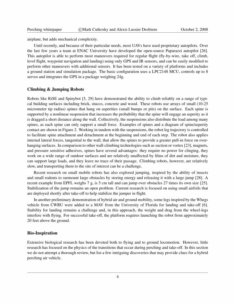
Robots like RiSE and Spinybot [5, 29] have demonstrated the ability to climb reliably on a range of typi-cal building surfaces including brick, stucco, concrete and wood. These robots use arrays of small (10-25micrometer tip radius) spines that hang on asperities (small bumps or pits) on the surface. Each spine issupported by a nonlinear suspension that increases the probability that the spine will engage an asperity as itis dragged a short distance along the wall. Collectively, the suspensions also distribute the load among manyspines, as each spine can only support a small force. Examples of spines and a diagram of spine/asperitycontact are shown in Figure 2. Working in tandem with the suspensions, the robot leg trajectory is controlledto facilitate spine attachment and detachment at the beginning and end of each step. The robot also appliesinternal lateral forces, tangential to the wall, that allow the spines to provide a greater pull-in force on over-hanging surfaces. In comparison to other wall-climbing technologies such as suction or vortex [23], magnets,and pressure sensitive adhesives, spines have several advantages: they require no power for clinging, theywork on a wide range of outdoor surfaces and are relatively unaffected by films of dirt and moisture, theycan support large loads, and they leave no trace of their passage. Climbing robots, however, are relativelyslow, and transporting them to the site of interest can be a challenge.
Recent research on small mobile robots has also explored jumping, inspired by the ability of insectsand small rodents to surmount large obstacles by storing energy and releasing it with a large jump [28]. Arecent example from EPFL weighs 7 g, is 5 cm tall and can jump over obstacles 27 times its own size [25].Stabilization of the jump remains an open problem. Current research is focused on using small airfoils thatare deployed shortly after take-off to help stabilize the jumper in flight.
In another preliminary demonstration of hybrid air and ground mobility, some legs inspired by the Whegsvehicle from CWRU were added to a MAV from the University of Florida for landing and take-off [6].Stability for landing remains a challenge and, in this approach, the weight and drag from the wheel-legsinterfere with flying. For successful take-off, the platform requires launching the robot from approximately20 feet above the ground.
Bio-Inspiration
Extensive biological research has been devoted both to flying and to ground locomotion. However, littleresearch has focused on the physics of the transitions that occur during perching and take-off. In this sectionwe do not attempt a thorough review, but list a few intriguing discoveries that may provide clues for a hybridperching air vehicle.
Figure 2: Left figure shows the new foot designed for perching. Notice the black area, made of sorbothane,at the ankle to increase the damping. The right figure shows the traced surface created when dragging aspine over a surface (concrete profile shown). Perchable regions are shown in bold and depend on frictionand spine geometry.
It has been suggested that flying evolved from the advantages of having small lifting surfaces [9] onrunning and jumping animals. Studies show that only a small amount of lift is required for control duringjumping and to reduce landing forces. The flying squirrel is one example of an animal that has evolved tocontrol landing forces. Its low aspect ratio wing provides aerodynamic stability and creates lift at angles ofattack up to 40 degrees without stalling. Squirrels deliberately stall themselves prior to landing, allowingthem to reduce by 60% their horizontal velocity before landing while spreading the impact over all fourlimbs [27, 8].
Legs and wings are used in combination in many bird and insect species. Birds able to take-off verticallycan produce up to 2G of acceleration with their legs before they start flapping their wings [22]. This createsan initial velocity and helps them to clear obstacles that could impede wing motion. At a much smaller scale,the fruit fly also uses a combination of wing thrust and stored energy in the legs. Voluntary take-offs makegreater use of the wings for control, but escape take-offs use the legs, with the wings held close to the body toachieve maximum jump height before switching to flight [10]. Some birds also use their wings for assistancein climbing, during which time they beat with a different stroke that provides a positive normal force againstthe wall, thus improving leg traction [7, 15].
The proposed project goal is to create a system that will allow a small fixed-wing airplane to perch au-tonomously on a variety of vertical surfaces for extended periods of time, crawl on the surface to reorientitself and take-off with the help of jumping. For the work in this section, we focus on a fixed-wing platformweighing approximately 500 grams. Significantly larger and heavier planes (e.g. Raven B in Table 1) cangenerally be designed to have greater endurance and are less suitable for the maneuvers required for perchingon arbitrary surfaces. Rotorcraft are capable of hovering and performing dramatic maneuvers [12] but arecomparatively noisy, slow and inefficient. In addition, landing, perching and crawling with rotorcraft maybe no easier than with a fixed-wing plane.
The proposed system will comprise a controller, an active suspension system and a sensor suite. Althoughit is initially focused on small fixed-wing MAVs, many of the underlying results can be transfered to otherplatforms (e.g. with deformable wings) in the second phase. In the following sections we first summarizesome of the key research challenges and questions that arise. We then propose a plan of research that willtake planes through the various stages of approach, landing and take-off.
Bio-Inspired Perching Air Vehicle DesignTaylor Cone, Alexis Lussier Desbiens, Mark Cutkosky - SURI 2008
Biomimetics & Dextrous Manipulation Laboratory
Overview
Foot Design Equipment
Suspension Performance Analysis
Hovering Stability Control
Throttle vs. Drag Analysis
Suspension Design
Perching Approach and Landing Maneuver
0 0.1 0.2 0.3 0.4 0.5 0.6 0.7 0.8 0.9 1!0.12
!0.1
!0.08
!0.06
!0.04
!0.02
0
0.02
0.04
Time (s)
Positio
n (
m)
0 0.1 0.2 0.3 0.4 0.5 0.6 0.7 0.8 0.9 1!15
!10
!5
0
5
Spin
e forc
e (
N)
Time (s)
! = 0.4, f = 3.14
! = 0.1, f = 0
Student Version of MATLAB
!0.2 !0.15 !0.1 !0.05 0 0.05 0.1 0.15!4
!3
!2
!1
0
1
2
3
4
Velocity (m/s)
Fo
rce
(N
)
Suspension 1 Actual
Suspension 1 Model
Suspension 2 Actual
Suspension 2 Model
Student Version of MATLAB
!0.5 !0.4 !0.3 !0.2 !0.1 0 0.1 0.2 0.3 0.4 0.5!6
!4
!2
0
2
4
6
Suspension Performance Analysis with Sinusoidal Forcing FunctionOptimal Parameters: k = 110 N/m, b = 5 N!s/m, f = 3 N, ! = 10 rad/s, A = 0.01 m
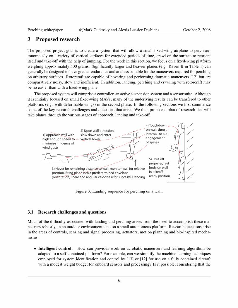
Figure 3: Landing sequence for perching on a wall.
3.1 Research challenges and questions
Much of the difficulty associated with landing and perching arises from the need to accomplish these ma-neuvers robustly, in an outdoor environment, and on a small autonomous platform. Research questions arisein the areas of controls, sensing and signal processing, actuators, motion planning and bio-inspired mecha-nisms:
• Intelligent control: How can previous work on acrobatic maneuvers and learning algorithms beadapted to a self-contained platform? For example, can we simplify the machine learning techniquesemployed for system identification and control by [13] or [12] for use on a fully contained aircraftwith a modest weight budget for onboard sensors and processing? Is it possible, considering that the
perching maneuvers only last 2-3 seconds, to reproduce the results with only GPS, accelerometer andgyroscope? Can we draw insights from the approaches taken by insects to achieve reliable landingsusing a small brain, well adapted passive mechanisms and integrated sensing?
• Sensing: What sensors will provide the most reliable information regarding wall detection, and planevelocity and attitude with respect to the wall before and after contact? Can we filter the noisy informa-tion to improve our knowledge of the system quickly enough to provide useful closed-loop correctionsduring landing? Will the sensors be sufficiently compact and robust? To what extent can the legs andtoes provide tactile sensing to improve knowledge about the state of the plane and the characteristicsof the wall?
• Legs and suspension: What are the optimal properties for the suspension system? What is the bestway to extract energy from the plane so that it can land gently? How can we create a suspensionthat will favor spine engagement for a range of incoming velocities and orientations? Can we obtainsufficient controllability using only semi-active elements (e.g. controlled brakes) that dissipate largeamounts of energy for their size and weight?
• Crawling: How can we control the plane using a combination of vectored thrust from the propellorand flaps, and actuation of the legs and toes, to move in a desired direction on the wall? Will theplanned maneuvers work on rough walls, when contact is intermittent?
• Gripping: How much gripping force must be generated to resist wing gusts? What is the best way todetect when a grip is failing so that the plane can recover before it falls?
• Jumping: How should jumping be integrated with the return to flight? How can the control surfacesof the plane be used to help stabilize the jump? How can the take-off approach be extended to MAVswith a thrust to weight ratio smaller than one?
• Ground effects: Can the changes in aerodynamics as the plane approaches a large wall be used tofacilitate landing? Are there specific lessons to be learned from animals such as flying squirrels andbats about exploiting ground effects on vertical surfaces?
• Platform design: What modifications can be made to the plane to provide more controllability duringlanding and take-off, and to increase the robustness of the plane, without impairing its flight perfor-mance?
3.2 The process of approaching, landing, gripping and take off
Figure 3 illustrates the sequence of actions required to perch on a wall with a fixed-wing plane. Initially, theplane approaches the wall at cruise speed. Upon wall detection (5 to 10m away), the plane pitches to slowdown and stays in that orientation until wall contact. The suspension then absorbs most of the impact in away that allows the spines, or other adhesive technologies, to engage the surface. To further enhance theprobability of spine engagement, some control is applied during the short landing phase (e.g., by keepingthe thrust oriented toward the wall) before complete rest. Once landed, the plane can reorient itself, remainstill for extended periods of time, or take-off as desired. The following section describes some of the coreactivities associated with each stage of the process.
In parallel, investigations into biological exemplars will provide inspiration for design and control princi-ples. Previous research has shown that much can be learned from joint biological and robotics investigationsto develop robots that run faster [11] or climb a range of surfaces using technologies like spines and dryadhesives [29, 5]. Similar results are expected from the investigations of landing, perching and controlledjumping in spiders, flying lizards and birds. These insights will inform the development of new MAVs, whichwill be inherently better suited to the requirements of frequent landing, perching, jumping and take-off.
To frame the discussion, we embed a cartesian coordinate frame (xs,ys,zs), as shown in Figure 4, at thespines, which are generally arranged in a short row on the tip of a toe. When the toes are properly aligned forgripping, the direction xs points upward along the wall, in the opposite direction of gravity, and zs is normalto the wall.
Stage 1 - Initial approach
The first stage encompasses steps 2-4 in the sequence in Figure 3. As the plane approaches the wall, the pa-rameters of interest include its distance to the wall, x f , its linear and angular velocity [vx f ,vy f ,vz f ,ωx f ,ωy f ,ωz f ]
T
and its orientation defined by bank, elevation and heading angles, [φ,θ,ψ]T. Our emphasis is particularly onthe final tens of centimeters of flight before contact, when there is little time for closed-loop control to mod-ify the state variables; consequently, the final maneuver will be largely open-loop. The goal is primarily tobring the plane’s final touchdown velocity, and bank and elevation angles, assuming small heading change,within an envelope E(φ,θ,vx f ,vz f ,ωx f ,ωy f ,ωz f ) in the instants before touchdown such that the next stagecan proceed.
The maneuver is accomplished using only the propeller and control surfaces. Initially, to maximizecontrol authority, the MAV will be taken from the class of lightweight acrobatic planes that can hover forshort periods of time (such as the plane in Figure 1). Subsequent work will expand the approach to MAVssuch as the Wasp-III [4] that cannot hover and have minimum flight speeds above 3m/s. In this case, the planemust execute an intentional stall just prior to contacting the wall. The methods used in [13] for perching aglider on a bar or wire may be applicable. However, an interesting feature of landing on an extended wallis that ground effects become important and can help with stabilization. MAVs with deformable wingsrepresent another interesting opportunity for exploring approaches like those taken by birds, flying squirrelsand bats to shed velocity rapidly in the final stages of flight [27].
For the proposed work, a controller derived from the open-source Paparazzi Autopilot Project will berefined and used to experiment with different landing trajectories for spine engagement. The developmentof entirely new MAVs and controllers is not initially a focus of the proposed work. We have established thatthe Classic board from Paparazzi for a vehicle such as the Flatana 3D aerobatic plane can be adapted for ourpurposes. We have implanted a new controller on this board, using a lightweight IMU and ultrasonic rangesensor, to achieve controlled hovering and transitions between flight and hovering in large indoor spaces.Although hovering has been accomplish with the IMU, the current algorithm combining the measurementsis designed only for small rotations. A more general filter is under development and will combine theinformation from GPS, accelerometers and rate gyroscopes to get a more accurate state estimation during3D maneuvers [24].
This sensors suite will then allow us to improve our plane’s model so that we can simulate, optimize[12] and implement specialized maneuvers for smooth landing and take off. The model will be createdusing a technique from [13, 1] adapted to onboard sensing. This approach consists in performing numeroustrajectories, similar to the desired task, and fitting a model that will minimize the prediction error given thecurrent state and action.
As the plane approaches a wall or other surface, absolute sensing of velocity and orientation with re-spect to the surface becomes possible. Candidate sensors include ultrasonic and optical (imaging, flow ortriangulation based) sensors, chosen for low weight, robustness, and the ability to produce information thatis not too noisy. Tests will be conducted to determine which combination of sensors is most effective. It isinteresting at this stage to investigate how animals, but mostly insects because of their limited sensing andintelligence, detect the wall and prepare themselves for landing.
In Phase II of the proposed work, we will investigate the use of deformable wings for increased durabilityfrom the impact, better aerodynamics during high angle of attack maneuvers and better exploitation of groundeffects to help in slowing down the plane.
Stage 2 - Stabilization and spine/asperity contact
After initial contact, the degrees of freedom of the plane are successively reduced as one and then both feetare brought into contact. Passive and active properties of the legs are now available for stabilizing the plane.The goal is to enter a smooth trajectory that lightly drags the spines down the wall to facilitate engagementwhile maintaining a small force normal to the wall. Our initial approach is to rely primarily on passivecompliance in the legs, based on previous success with under-actuated leg mechanisms in Spinybot [5].The suspension needs to be designed to provide the desired force and motion trajectory. On surfaces with
smaller asperities, the thrust vector can be oriented slightly toward the wall to provide more normal forceand increase the likelihood of the spines grasping an asperity (Figure 2).
0 0.1 0.2 0.3 0.4 0.5 0.6 0.7 0.8 0.9 1−0.15
−0.1
−0.05
0
0.05
Posit
ion
(m)
0 0.1 0.2 0.3 0.4 0.5 0.6 0.7 0.8 0.9 1−15
−10
−5
0
5
Spin
e fo
rce
(N)
time (sec)
ζ = 0.4, f = 3.14ζ = 0.1, f = 0
Max extension
Max rebound
Max force
Figure 5: Comparison of conventional lightly-damped suspension and nonlinear hysteretic and frictiondamping suspension. The nonlinear suspension eliminates the rebound which would make the spines re-lease and reduces the maximum force.
The role of the suspention is to favor engagement of the spines, in the presence of uncertainties. To doso, the suspension must absorb the landing impact without creating any rebound, while also minimizing therequired suspension travel and the forces transmitted to the airplane. In preliminary work, we have developeda nonlinear passive leg suspension (shown in the photograph in Figure 2 and modeled in Figure 5), that usesa combination of friction and hysteretic damping to prevent any rebound in the force loading the spines.This is important because the spines can resist normal forces as long as they are loaded in shear. Assumingthe plane is moving downward, dragging its spines on the wall, the nonlinear suspension is much betterat ensuring successful spine loading. The next step is to extend the analysis to a multi-degree of freedomproblem involving loading in all three directions. Particular attention will be paid to mechanisms used byanimals during perching on vertical surfaces and the roles of tendons, muscles and skeleton for stabilization,force dissipation and spine or claw engagement.
In parallel with numerical modeling of active and passive leg mechanisms it is important to conducttests of landing trajectories. Unfortunately, running many landing tests will initially result in many crashes,requiring repairs to the plane. A more efficient solution for exploring the envelope of possible initial con-ditions is to use a high speed robot arm to repeatedly launch an inexpensive, crashworthy airplane proxy,equipped with legs, toes and spines, toward the wall. For this purpose, we can use the Adept One MV robotat Stanford. This robot is capable of tip speeds up to 9m/s, which is more than adequate for testing ourlanding strategies and starting to establish the “envelope” of feasible orientations and velocities from whichattachment can proceed. In Figure 6, the Adept grasps the plane and brings it to a specified orientation and
velocity with respect to wall before releasing the plane, which then travels without active control until itgrasps the wall surface.
Figure 6: Sequence of images of the Adept robotic arm being used to throw the plane on a specific trajectory.
One of the challenges in designing the leg suspension is that traditional shock absorbers and actuators areundesirably heavy. The leg will therefore need to exploit nonlinear viscoelastic materials and friction brakes,etc. Our lab has designed prototypes of small and lightweight mechanically-tuned systems composed ofdifferent materials using Shape Deposition Manufacturing [11, 5]. In early experiments, we have used theAdept robot to test the suspension, at various speeds and trajectories, on an un-powered plane to help usdevelop designs that we can compare with simple numerical models.
Figure 7 shows a comparison of experimental and actual forces and velocities for two different designs.Suspension 2 is an improved version of Suspension 1, with greater damping due to nonlinear friction ele-ments. This suspension, although still not optimized, performs significantly better, allowing the airplane toland with initial velocities as high as 2.5 m/s.
Stage 3 - Spine loading and gripping
At the start of the final stage, the spines are traveling along the wall. We know from prior work [5, 29]that the ability of spines to engage asperities on a surface is a function of several factors, particularly spinetip radius compared to average asperity size, surface roughness properties including the average amplitude,narrowness and slant of peaks and valleys, number of spines per foot and the spine approach vector, whichcreates a swept volume that interacts with the surface. The general problem is captured in Figure 2, whichshows a spine creating a traced surface as it slides along a concrete profile. The marked regions are those onwhich the spine can perch. Spine and asperity strength both scale as L2, however, the probability of findingan asperity large enough to perch on scales roughly as 1/L2 for many surfaces such as concrete and stone,
Figure 7: Testing of two different suspensions. Suspension 1 has a damping ratio of 0.02 and fails if thevertical (downward) velocity at landing is higher than 0.8 m/s. Suspension 2 has a higher damping ratio(0.23) and gives the plane a larger envelope of initial conditions, with vertical velocities up to 2.5 m/s.
which have a fractal surface characteristic over some range of length scales. Practically speaking, for spineswith a tip radius of 10 µm or greater, surfaces equivalent to 120 grit sandpaper or rougher will present enoughasperities per unit area for reliable gripping.
Spines can sustain loads of approximately 3.5N on surfaces like sandstone or concrete. Thus for thecurrent plane (350 grams), only a few spines are needed on each toe. A total of 10 spines is currently used toabsorb the dynamic load of landing (5 grams per foot, without any weight optimization), usually 2-10 timeshigher than the static weight of the plane depending on the touchdown velocity and suspension design. Onfriable surfaces like adobe, more spines may be needed to avoid failure of the surface asperities.
The spines are supported by a compliant suspension in the toe, whose stiffness can be defined at any in-stant with a configuration-dependent stiffness matrix, K. The design of multimaterial elastic toe mechanismswill build upon previous work for Spinybot, RiSE and Zman [5, 29]. In the present case, the parametersof the stiffness matrix should be such that initially the stiffness in the Z direction is very low (to preventbouncing) and the off-diagonal terms Kxz, Kxθ, Kzθ should be low to prevent rotation of the spine, whichcould cause it to slip off an asperity.
Because spines are directional, they only engage asperities and resist combinations of tangential andnormal force from a single direction. For a climbing robot, the weight of the robot is sufficient to load thespines, but for a MAV, especially in windy weather, we cannot rely on gravity. The solution is to use opposedpairs of spines. Rough prototypes have resisted pull-off forces as large as 10 N (Figure 8). Improved versionswill use actuators for automatic deployment. Opposition can occur within a foot, with toes having opposingspine directions, or between feet, using one or more actuated feet near the tail of the airplane.
Figure 8: The figure on the left shows an unpowered replica of the plane clinging to a wall with compliantlegs. This linkage allows impact absorption at the ankle and knee joints, while favoring spine engagement.The knee and ankle provide a combination of stiffness, damping and friction. The figure on the right showsan early prototype of opposing spines passively holding 600g.
Wall maneuvers and take-off
During Phase II of the proposed work we will explore strategies for using a combination of propeller powerand legs with spines to execute maneuvers on the wall. The first of these maneuvers is crawling forward,inspired by wing-assisted climbing [7, 15] in a few bird species, and can be achieved using the propeller andthe plane control surfaces to guide the legs. Note that with spines in contact, each foot can slide forwardbut not backward. Using this crawling motion, the plane can be slowly reoriented to get a better observationangle or reach a more secure location.
Another maneuver that could benefit from interaction with the wall is to do a jump assisted take-off.This would allow the plane to reach airspeed almost immediately after it disengages its spines and to clearthe wall with minimum altitude lost. Such maneuvers would be especially useful on planes with a thrustto weight ratio less than unity. The mechanism for storing elastic energy and releasing it can be adaptedfrom other recently developed small jumping robots [25]. We will also investigate whether the elastic anddamping mechanisms that stabilize the plane during landing could be effective during takeoff as well.
While not related to perching, that jump assisted take-off ability could be useful on the ground as well.Most MAVs are so light than they can land successfully and robustly by doing a simple “crash” onto theground. But take-off remains a problem, especially on uneven terrain. A jump-assisted take-off could over-come this problem.
In summary, the process of landing and perching can be decomposed into a series of clearly defined stagesthat make it feasible for a small plane to execute the entire sequence autonomously. The main challenge willbe to do it reliably, in the presence of sensor noise, wind gusts, etc. Much of the proposed work is aimedat developing robust solutions for mechanisms, sensor interpretation and control that will provide reliableoperation under realistic conditions.
[1] Pieter Abbeel, Varun Ganapathi, and Andrew Y Ng. Real-time attitude and position estimation forsmall uavs using low-cost sensors. Neural Information Processing Systems, 18:8, 2006.
[5] Alan T Asbeck, Sangbae Kim, M.R Cutkosky, William R Provancher, and Michele Lanzetta. Scalinghard vertical surfaces with compliant microspine arrays. International Journal of Robotics Research,25(12):14, Sep 2006.
[6] Richard J Bachmann, Frank J Boria, Peter G Ifju, Roger D Quinn, Jeffrey E Kline, and RaviVaidyanathan. Utility of a sensor platform capable of aerial and terrestrial locomotion. InternationalConference on Advanced Intelligent Mechatronics, pages 1581–1586, Aug 2005.
[7] Matthew W Bundle and Kenneth P Dial. Mechanics of wing-assisted incline running (WAIR). Journalof Experimental Biology, 206:4553–4564, 2003.
[8] Greg Byrnes, Norman T.-L Lim, and Andrew J Spence. Take-off and landing kinetics of a free-ranginggliding mammal, the malayan colugo (galeopterus variegatus). Proceedings of the Royal Society B:Biological Sciences, 275(1638):1007–1013, Feb 2008.
[9] Gerald Caple, Russell P Balda, and William R Willis. The physics of leaping animals and the evolutionof preflight. The American Naturalist, 121:455–467, Sep 1983.
[10] G Card and M Dickinson. Performance trade-offs in the flight initiation of drosophila. Journal ofExperimental Biology, 211(3):341–353, Feb 2008.
[11] Jorge G Cham, Sean A Bailey, Jonathan E Clark, Robert J Full, and Mark R Cutkosky. Fast and robust:Hexapedal robots via shape deposition manufacturing. The International Journal of Robotics Research,21(10):14, Mar 2002.
[12] Adam Coates, Pieter Abbeel, and Andrew Y. Ng. Learning for control from multiple demonstrations.Proceedings of the 25th International Conference on Machine Learning, 2008.
[13] Rick Cory and Russ Tedrake. Experiments in fixed-wing uav perching. Proceedings of the AIAAGuidance, Navigation, and Control Conference, Aug 2008.
[14] DelFly. DelFly II home page. http://www.delfly.nl/, 2008.
[15] K. P Dial. Wing-assisted incline running and the evolution of flight. Science, 299(5605):402–404, Jan2003.
[16] Draganfly. Draganfly.com industrial aerial video systems & UAVs. http://www.draganfly.com, 2008.
[17] Adrian Frank, James S McGrew, Mario Valenti, Daniel Levine, and Jonathan P How. Hover, transition,and level flight control design for a single-propeller indoor airplane. AIAA Guidance, Navigation andControl Conference, Aug 2007.
[18] Joel M Grasmeyer, Matthew T Keennon, and Aerovironment. Development of the black widow microair vehicle. 39th AIAA Aerospace Sciences Meeting and Exhibit, Oct 2001.
[19] W Green and P Oh. Autonomous hovering of a fixed-wing micro air vehicle. IEEE InternationalConference of Robotics and Automation.
[20] W Green and P Oh. A mav that flies like an airplane and hovers like a helicopter. Advanced IntelligentMechatronics. Proceedings, Jan 2005.
[21] W Green and P Oh. A fixed-wing aircraft for hovering in caves, tunnels, and buildings. AmericanControl Conference, Jan 2006.
[22] Frank H Heppner and John G.T Anderson. Leg thrust important in flight take-off in the pigeon. Journalof Experimental Biology, 114:285–288, Mar 1985.
[23] Lewis Illingworth and David Reinfeld. Vortex attractor - US 6,565,321 B1. United States Patent,page 40, Sep 2003.
[24] Derek B. Kingston and Randal W. Beard. Real-time attitude and position estimation for small uavsusing low-cost sensors. AIAA 3rd Unmanned Unlimited Systems Conference and Workshop, September2004.
[25] Mirko Kovac, Martin Fuchs, Andre Guignard, Jean-Christophe Zufferey, and Dario Floreano. A minia-ture 7g jumping robot. International Conference on Robotics and Automation, pages 373–378, 2008.
[26] Paparazzi. Paparazzi, the free autopilot. http://paparazzi.enac.fr, 2008.
[27] K. E Paskins, A Bowyer, W. M Megill, and J. S Scheibe. Take-off and landing forces and the evolutionof controlled gliding in northern flying squirrels glaucomys sabrinus. Journal of Experimental Biology,210(8):1413–1423, Apr 2007.
[28] Umberto Scarfogliero, Cesare Stefanini, and Paolo Dario. Design and development of the long-jumpinggrillo mini robot. IEEE International Conference on Robotics and Automation, Feb 2007.
[29] M.J Spenko, G.C Haynes, J.A Saunders, M.R Cutkosky, A.A Rizzi, and R.J Full. Biologically inspiredclimbing with a hexapedal robot. Journal of Field Robotics, Feb 2008.
The control system for hovering is based on three sensors: a 3-axis accelerometer (ADXL330 rated at ±3g),a 3-axis rate gyroscope (two IDG300 rated at 500 deg/sec) and a ultrasonic range sensor (SRF02). Bothaccelerometer and gyroscope are acquisitionned at 60Hz while the SRF02 is updated at 10Hz. The weightof all these sensors is less than 10 grams.
The idea of the control scheme is to combine the gravity vector measurement from the accelerometer atlow frequency with the angular rate of the gyroscope at high frequency to get accurate attitude estimationfor control. This filter eliminates the drift that we would result from the gyroscope integration, and providesaccurate measurement at higher frequency than if the accelerometer alone was used. We are using a second-order complementary filter to combine the measurement in a simple and efficient way.
θ(s)(
τs+1τs+1
)2
=τ2s
(τs+1)2 θ̇g(s)+2τs+1
(τs+1)2 θa(s) (1)
where θ̇g and θa are respectively the gyroscope and accelerometer measurements. A value of τ = 1rad/sec was found to provide an good balance between the gyroscope and accelerometer measurements.
Pitch and Yaw
The controller, for pitch and yaw, was first designed using the Ziegler-Nichols method, then transformed ina lead filter:
Hyaw = 2000s+5.3
s+26.5(2)
Before being used by this controller, the pitch and yaw measurement are low pass filtered at about 15Hz. The controller uses the input from the RC controller for trimming.
Roll
The roll controller consists of a proportional controller around the gyro measurement. It damps the rollmotion enough so that the desired position is maintained through the hovering or perching maneuver. Thesignal from the gyro is also low-pass filtered at 2Hz.
Altitude
The SRF02 currently used for the altitude control has a fairly low update rate and a much shorter range thancalled for in the specifications. We are currently looking for a replacement. If the SRF02 is used alone, thecombined sensor and motor delays produces large oscillations.
Stable hovering has been achieved using successive loop closure. An inner loop, based on the accelerom-eter measurement, eliminates the slow dynamics of the motor and sensor while the outer loop uses the SRF02measurement to control the altitude. This result in stable altitude control.


![Shape memory alloy-based small crawling robots inspired by ... · material for many biologically inspired robots such as worm-like robots [12], the bending actuation of an IPMC is](https://static.documents.pub/doc/80x56/5fbd02e298ad5d4fd41f1ccb/shape-memory-alloy-based-small-crawling-robots-inspired-by-material-for-many.jpg)


