BioCTS: AN MRT User Guide Version 1.1 NIST/ITL CSD Biometric Conformance Test Software using ANSI/NIST-ITL Machine Readable Tables August 31, 2017 Christofer J. McGinnis ID Technology Partners (NIST Associate) Software Developer / Biometric Engineer Dylan Yaga NIST/ITL CSD Software Designer / Project Manager National Institute of Standards and Technology (NIST) Information Technology Laboratory (ITL) Computer Security Division (CSD)
Transcript
BioCTS: AN MRT User Guide
Version 1.1
NIST/ITL CSD Biometric Conformance Test Software using
ANSI/NIST-ITL Machine Readable Tables
August 31, 2017
Christofer J. McGinnis
ID Technology Partners (NIST Associate) Software Developer / Biometric Engineer
National Institute of Standards and Technology (NIST)
Information Technology Laboratory (ITL)
Computer Security Division (CSD)
i
Contents Disclaimer..................................................................................................................................................... iv
Version History .............................................................................................................................................. v
Conformance Testing Support .................................................................................................................. 4
Testing Support for MRT Elements ....................................................................................................... 4
Testing Support Exceptions ................................................................................................................... 4
Level-2 Support Details ......................................................................................................................... 4
Test Results ............................................................................................................................................... 6
(1) Test Name ........................................................................................................................................ 6
(2) Test Level ......................................................................................................................................... 6
(3) Test Result ....................................................................................................................................... 7
(4) Test Message ................................................................................................................................... 7
Test Reports .............................................................................................................................................. 8
BioCTS AN MRT GUI ...................................................................................................................................... 9
Running BioCTS AN MRT GUI Edition ........................................................................................................ 9
File Information ................................................................................................................................... 13
Status Label ......................................................................................................................................... 13
Record Editing ..................................................................................................................................... 15
Field Editing ......................................................................................................................................... 17
Features .................................................................................................................................................. 22
General Flags ....................................................................................................................................... 22
One XML Element Representing Multiple Traditional Entities ........................................................... 29
Specifying TOT Requirements ................................................................................................................. 30
TOT Record Set Occurrence Requirements ........................................................................................ 31
TOT Field Occurrence Requirements .................................................................................................. 32
MRT Elements ......................................................................................................................................... 32
Standard Defects ..................................................................................................................................... 41
Record Header Length ........................................................................................................................ 41
98.900 IID Character Counts ............................................................................................................... 42
XML Overlap Issues ............................................................................................................................. 43
Tables and Figures Figure 1 – Test Name Formats ...................................................................................................................... 6
Figure 2 – Test Message Reference Formats ................................................................................................ 7
Figure 3 – Text Output Result Example ......................................................................................................... 8
Figure 18 – Table of standard supported by default MRTs ........................................................................ 41
Figure 19 – Record Header Field xx.001 / LEN requirements ..................................................................... 42
Figure 20 – Smallest possible record length ............................................................................................... 42
Figure 21 – MRT Updated LEN Requirements ............................................................................................ 42
iv
Disclaimer NIST/ITL CSD BioCTS AN MRT Edition
October 2010
The software was developed by the National Institute of Standards and Technology (NIST), an agency of the Federal Government. Pursuant to Title 15 United States Code Section 105, works of NIST are not subject to copyright protection in the United States and are considered to be in the public domain. Thus, the software may be freely reproduced and used. Please explicitly acknowledge the National Institute of Standards and Technology as the source of the software. This software is released by NIST as a service and is expressly provided "AS IS." NIST MAKES NO WARRANTY OF ANY KIND, EXPRESS, IMPLIED OR STATUTORY, INCLUDING, WITHOUT LIMITATION, THE IMPLIED WARRANTY OF MERCHANTABILITY, FITNESS FOR A PARTICULAR PURPOSE, NON-INFRINGEMENT AND DATA ACCURACY. NIST DOES NOT REPRESENT OR WARRANT THAT THE OPERATION OF THE SOFTWARE WILL BE UNINTERRUPTED OR ERROR-FREE, OR THAT ANY DEFECTS WILL BE CORRECTED. NIST does not warrant or make any representations regarding the use of the software or the results thereof, including but not limited to the correctness, accuracy, reliability or usefulness of the software. By using this software or by incorporating this software into another product, you agree to hold harmless the United Sates Government for any and all damages or liabilities that arise out of such use. Certain trade names and company products are mentioned in the text or identified. In no case does such identification imply recommendation or endorsement by the National Institute of Standards and Technology, nor does it imply that the products are necessarily the best available for the purpose. With the exception of material marked as copyrighted, information presented in this document is considered public information and may be distributed or copied. Use of appropriate byline/photo/image credits is requested.
v
Version History
Version Revision Date
Authors
Description
1.0 2017-04-10 McGinnis, Christofer; Yaga, Dylan
Initial Version
1.1 2017-08-21 McGinnis, Christofer • Indication that all Level-2 MRT elements are now supported
• Added Level-2 Support Details, describing how BioCTS parses and tests the related MRT-defined requirements
• Added description of how Undefined Fields are handled in the section on “Specifying ANSI/NIST-ITL Requirements”
• Modified description of Field Definitions > MRT Elements > <CondCode>
• Modified description of Field Definitions > MRT Elements > <MaxOccur> and <MinOccur> for Tagged Fields
• Added Static Requirement: “Tagged Field Duplicates”
• Updated CLI -tprompt flag description and added -nolevel2 flag
• Added descriptions for XML_Min and XML_Max for TOTField
• Added clarification of how <InfoItem> must be equal to SET in order for information items to be associated with the parent.
• Added description for AppliesIf notation in TechNotes.
• Minor editorial updates
1
Scope All information provided in this document applies to Version 1.1 of BioCTS AN MRT applications. Other
versions of BioCTS AN MRT applications may not provide the same functionality or behavior. For other
versions, please refer to the appropriate documentation. For supplemental documents listed
throughout this document, please refer to the versions listed in the References section.
Introduction NIST/ITL CSD supports the development of biometric conformance testing software, including the
Biometric Conformance Test Software (BioCTS) family of applications. BioCTS, which has been freely
available1 since 2012, supports conformance testing of biometric data interchange format standards
developed by the International Committee for Information Technology Standards (INCITS), the
International Organization for Standardization (ISO), and the American National Standard Institute
(ANSI).
While BioCTS broadly supports conformance testing for many biometric specifications, versions that
support the ANSI/NIST-ITL (AN-ITL) line of standards have received a great deal of development support.
The evolving nature of the AN-ITL standard, its many profiles for specific application domains, and its
extensive use in U.S. government and international communities all necessitate efforts to provide robust
conformance testing solutions.
In early 2017, a suite of BioCTS applications was released to support user-defined requirements and
profiles for AN-ITL specifications. These applications make use of configuration files to dynamically
generate parsing rules and conformance requirements for any version or profile of the AN-ITL standard.
The configuration files utilize a format called ANSI/NIST-ITL Machine Readable Tables (MRTs), which are
XML-based. The BioCTS AN-ITL applications that use MRTs are collectively referred to as BioCTS AN
MRT. This document provides an overview of the features common among all BioCTS AN MRT
applications, specific details about installing and operating each application, and details regarding the
use of MRT configurations with BioCTS software.
Motivation for Configurable Requirements Development of BioCTS applications traditionally relied on the publication of Conformance Testing
Methodology (CTM) documentation, which specified the test assertions required to sufficiently assess
conformance to requirements found in the related biometric standard. Manual software development
was then required to code each of the assertions listed in the CTM documentation. This process
required a large amount of development time after the publication of the standard and related CTM,
and often resulted in long delays in the release of conformance tools. This approach also defined
conformance tests statically, meaning that:
• End users with domain-specific requirements or user-defined fields were not able to modify the
conformance tests or parsing rules.
1 BioCTS is hosted by NIST and available for download at: https://www.nist.gov/itl/csd/biometrics/biometric-
This is the same format as Fields and Information Items, except that the SubField Occurrence is entered in braces.
2nd Subfield in 1.003-CNT Info Item Count:
[01.003:T][1/CNT:T]{2}-InfoItemCount
Records Record[RecordType]-Description Where the RecordType is the number of the Record Type being tested.
Record Type-1 Field 1 is first: Record[1]-Field001IsFirst
Transactions Transaction-Description
Transaction has data present: Transaction-Data-Present
Description indicates the type of test being performed, and may or may not be the name of a specific element in
the MRT documents.
Figure 1 – Test Name Formats
(2) Test Level There are four valid levels of testing: L1, L2, L3, and Parse.
The level of testing is an indicator of the complexity and type of test being performed. Levels 1 through
3 (L1, L2, and L3) are described in the ANSI/NIST-ITL standard. The levels generally indicate the level of
complexity required for the test, with 1 being the least complex and 3 the most complex. The MRT
format does not currently support L3 testing. Many of the requirements defined by the MRTs are L1 (for
example value, character-type, occurrence, and data length tests). L2 testing includes inter-field and
conditional testing. Many L2 tests have specific MRT XML elements to assist in their definition. See
Level-2 Support Details for more information.
7
In addition to L1 through L3 tests, some tests are labeled as Parse. All Parse-level tests are defined in
this document as static (non-modifiable) requirements. These tests are necessary for reliable parsing of
any AN-ITL formatted transaction and cannot be modified using the MRTs.
(3) Test Result There are four valid types of Test Result:
• Ok – No Warnings, Errors or Critical Errors were found
• Warning – No Errors or Critical Errors were found, but warranted a warning statement (i.e. an
“Unspecified” value, etc.)
• Error – The test failed
• Critical Error – The test failed and may be preventing other tests from being performed
(4) Test Message A description of how the test was performed. The message sometimes includes an error message.
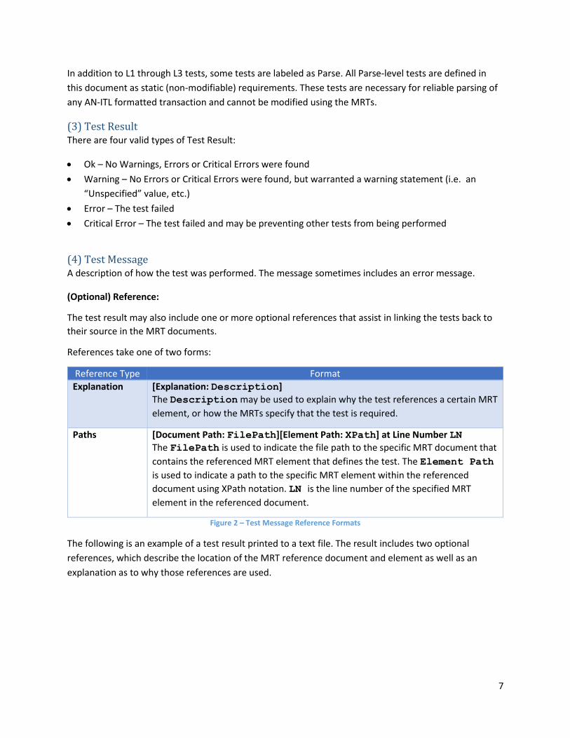
(Optional) Reference:
The test result may also include one or more optional references that assist in linking the tests back to
their source in the MRT documents.
References take one of two forms:
Reference Type Format
Explanation [Explanation: Description]
The Description may be used to explain why the test references a certain MRT
element, or how the MRTs specify that the test is required.
Paths [Document Path: FilePath][Element Path: XPath] at Line Number LN
The FilePath is used to indicate the file path to the specific MRT document that
contains the referenced MRT element that defines the test. The Element Path
is used to indicate a path to the specific MRT element within the referenced
document using XPath notation. LN is the line number of the specified MRT
element in the referenced document.
Figure 2 – Test Message Reference Formats
The following is an example of a test result printed to a text file. The result includes two optional
references, which describe the location of the MRT reference document and element as well as an
explanation as to why those references are used.
8
Figure 3 – Text Output Result Example
Test Reports BioCTS AN MRT applications are capable of producing test results in text and XML formats. A Batch
Result Summary log is also produced if more than one file is tested. This summary will provide an
overview of testing results, including which MRT configurations were used, the number of files passing
and failing for each configuration, and a summary of total results by type for each file and configuration
combination.
9
BioCTS AN MRT Graphical User Interface (GUI) This section describes the BioCTS AN MRT GUI application (V.1.1.0.0), which provides a powerful
graphical interface for testing and editing AN-ITL transactions. Screen captures of the application are
provided for illustration only and may not represent the final software release.
Running BioCTS AN MRT GUI Edition The application may be launched by double clicking the BioCTS icon or executable.
Loading Screen After launching the application, a BioCTS AN MRT Loading Window will appear. This loading screen will
remain open until the initial configuration file3 and MRT files are loaded and parsed. A status message
indicator at the bottom of the screen will update to provide details about the loading process.
Figure 4 – Loading Screen
Batch Testing This section outlines features in the user interface that facilitate loading, testing, and
analyzing transactions. The “Transaction Batch Test” tab allows multiple transactions (files) of any
encoding to be loaded and tested together. The overall result for each transaction is displayed in the
“Files Under Test” pane. All MRT configurations loaded from the configuration file (and selected on the
Options tab) will be shown in the “Files Under Test” pane as column headers. Each loaded file path will
appear as a new row. The intersection of the configuration and file path will hold the result of the
conformance test after it is completed.
3 The configuration file may be selected using the Options Tab. Upon the first time loading the application, the default configuration file is loaded.
10
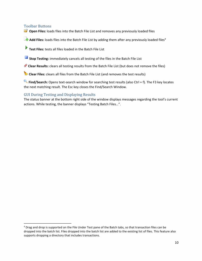
Toolbar Buttons Open Files: loads files into the Batch File List and removes any previously loaded files
Add Files: loads files into the Batch File List by adding them after any previously loaded files4
Test Files: tests all files loaded in the Batch File List
Stop Testing: immediately cancels all testing of the files in the Batch File List
Clear Results: clears all testing results from the Batch File List (but does not remove the files)
Clear Files: clears all files from the Batch File List (and removes the test results)
Find/Search: Opens text-search window for searching test results (also Ctrl + f). The F3 key locates
the next matching result. The Esc key closes the Find/Search Window.
GUI During Testing and Displaying Results The status banner at the bottom right side of the window displays messages regarding the tool’s current
actions. While testing, the banner displays “Testing Batch Files…”.
4 Drag and drop is supported on the File Under Test pane of the Batch tabs, so that transaction files can be dropped into the batch list. Files dropped into the batch list are added to the existing list of files. This feature also supports dropping a directory that includes transactions.
11
Figure 5 – Batch Testing In Progress
The “Batch File List” will display each transaction’s overall result for each configuration, indicated by
either:
• - Overall Result of Fail
• - Overall Result of Pass
Once all files in the Batch File List have completed testing, the status banner at the bottom of the
window will change to green and display “Test Complete! …” followed by the time elapsed during
testing.
Textual output results for each transaction can be viewed by clicking on the desired result cell in the
“File Under Test” pane. The complete textual results are displayed in the pane to the right.
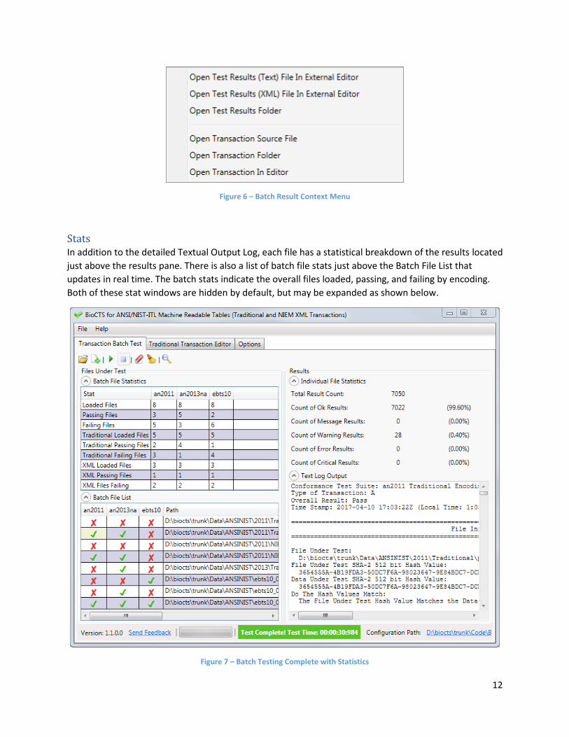
Context Menu A context menu is available when transaction files are loaded in the Batch File List found in the “File
Under Test” pane. By right-clicking on any of the cells, a context menu is displayed with options to open
the results files or the source data files. An option to open the transaction in the Traditional Transaction
Editor is also available (Traditional encoding only).
12
Figure 6 – Batch Result Context Menu
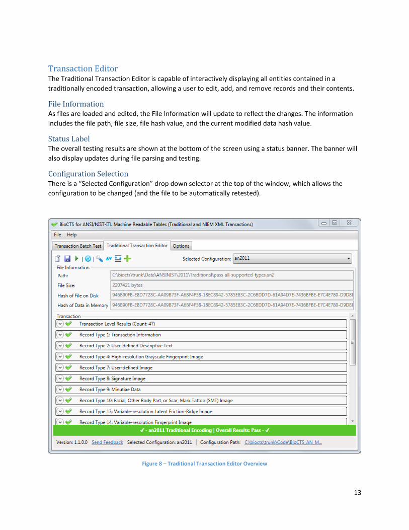
Stats In addition to the detailed Textual Output Log, each file has a statistical breakdown of the results located
just above the results pane. There is also a list of batch file stats just above the Batch File List that
updates in real time. The batch stats indicate the overall files loaded, passing, and failing by encoding.
Both of these stat windows are hidden by default, but may be expanded as shown below.
Figure 7 – Batch Testing Complete with Statistics
13
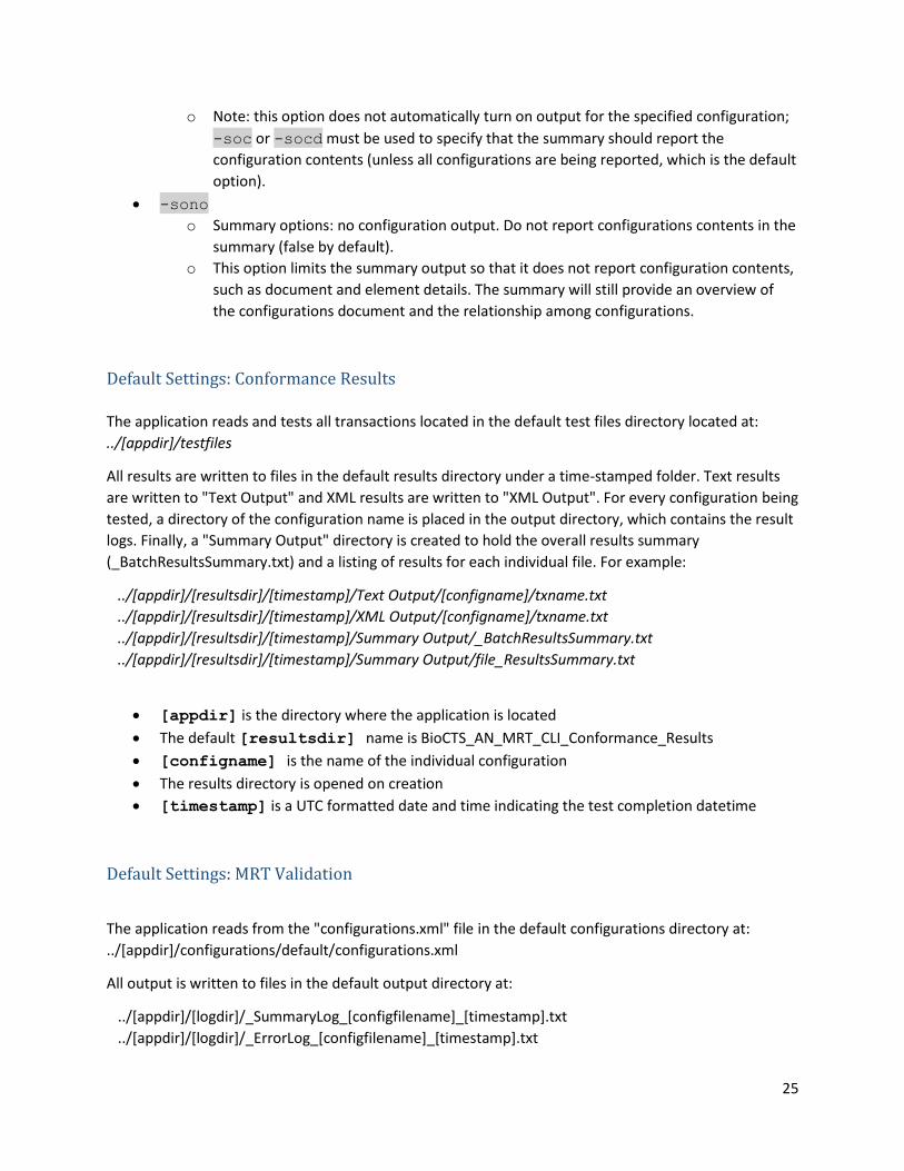
Transaction Editor The Traditional Transaction Editor is capable of interactively displaying all entities contained in a
traditionally encoded transaction, allowing a user to edit, add, and remove records and their contents.
File Information As files are loaded and edited, the File Information will update to reflect the changes. The information
includes the file path, file size, file hash value, and the current modified data hash value.
Status Label The overall testing results are shown at the bottom of the screen using a status banner. The banner will
also display updates during file parsing and testing.
Configuration Selection There is a “Selected Configuration” drop down selector at the top of the window, which allows the
configuration to be changed (and the file to be automatically retested).
Figure 8 – Traditional Transaction Editor Overview
14
The Editor5 is designed to display as little or as much data as desired by the user by making use of
expander sections, which can be expanded to display more information by pressing the button
within sections. Below is a brief description of the tools6 available in the Editor:
Open File: Loads a single file into the Editor and automatically tests it7
Save File: Saves the file to disk (location chosen by user) with any modifications from Editor
Test Files Tests or re-tests the file currently loaded into the Editor
Reload from Disk: Reloads the current file from disk, discarding any changes from the Editor
Auto Fix: Attempts to fix common file issues with Record Length and Transaction Contents
Sort: Sorts fields or records numerically (context dependent)
Organize/Arrange: Manually repositions fields or records using arrows (context dependent)
Add: Add field or record (context dependent)
Remove/Delete: Removes a field or record (context dependent)
Modify Subfields: Change number of subfields and information items (with or without data)
View/Modify Data: Displays data in a pop-out window and allows editing
Show Record Image: Attempts to display the image found in the record (context dependent)
The Editor displays three types of Results indicators for Records, Fields, Subfields, and Information
Items:
- Passing Test Indicator - Failing Test Indicator - No Tests Results Indicator
Expanding Transaction Hierarchy The Editor displays the data and associated results in an expandable, hierarchical format, and allows
editing of existing data using text fields. Each entity in the transaction can be expanded to reveal child
entities, such as records, fields, subfields, and information items. Any data within the transaction can be
edited, saved to disk, or loaded into a pop-out window for easier viewing and editing. In the following
image, Record Type-1 is expanded to reveal its fields, and Field 1.005 is expanded to reveal its data,
5 Many Editor tools and actions, including adding or removing Records, Fields, and Subfields, cause the transaction to be re-tested automatically. In some cases, the Auto Fix feature will also be run to ensure the Transaction is formatted properly after a modification takes place. For example, the removal of a Field will necessitate an adjustment to the Record Header Length to prevent parsing errors. 6 All options for modifying or organizing fields are disabled for the first field in each record type (Field xx.001). The first field in each record is required for parsing because it specifies the record length. 7 Drag and drop is supported on the Transaction area of the Traditional Transaction Editor tab so that files may be loaded into the editor.
15
which is editable. The red checkmarks indicate entities with failing tests. Those test results may be
shown by expanding the results section.
Figure 9 – Traditional Transaction Editor Expanded
Record Editing When a record is expanded, the Editor displays a list of the fields contained in the record.
Adding and Removing
The selected or expanded Record may be deleted by clicking the “Remove Record” button. In any
expanded Record, the Add, Sort, and Organize Field options are available.
16
New Records may be added by clicking the green plus icon . The user will be prompted for a Record
Type number.
Figure 10 – The Editor Add Record Dialog
Moving and Reordering
The Records may also be reorganized within the Transaction by using the numerical sort or the
manual rearrange buttons.
Figure 11 – The Editor Organize Records Dialog
17
Viewing Images
If the selected Record contains an image, the “Show Record Image” button will be available. Clicking
the button will show the image and its metadata. If the image type is not supported or cannot be read
by BioCTS, a “No Preview Available” message will be displayed.
Figure 12 – Editor View Image Window
Field Editing Each field displays expanders for the field-level results and the data that is held within the field. At this
level, a Field can be deleted from a record. The values in the data text fields can be edited. Three
buttons are provided to assist when a large amount of data is being manipulated (such as in an image
field):
Load Data: Loads data into the contents of a field/subfield/information item
Save Data: Saves the contents of a field/subfield/information item to a file
Pop-Out Data: Displays data in a large pop-out window for easy viewing and editing. If
the data is too long to display in the standard editor text field (such as image data), the pop-
out data window may be used for viewing and editing.
Subfield Structures
All Fields technically contain at least one Subfield which contains at least one Information Item (see
“How separators are used” in Annex B of NIST SP 500-290 Rev. 1). For Fields defined in the MRTs as
having <ContentType> of Data, Data_T, or Data_X, the editor shows one subfield containing one
information item which contains the data.
The “Modify Subfields” button allows the user to modify the number of Subfields and Information Items,
and decide whether to keep the current data. In the example below, a second Information Item is being
added (indicated by <ITEM>), and the previous data is retained in the first Information Item.
18
Figure 13 - The Modify Subfields Dialog
Subfield Editing
When a Field is expanded that contains multiple Subfields or Information Items, the containing Subfields
and Information Items are displayed with their own set of data and Results. The Subfields and
Information Item data can be edited in the same manner as Field data, by using the provided text field
or the provided buttons for loading, saving, and modifying data.
19
Options The “Options” tab provides the testing and output customization choices described below8. Note that
the Options tab is disabled during testing to prevent changes that may compromise the integrity of the
Test Results.
Figure 14 – Options Tab
• Configuration File Path: This allows the user to specify the location of an MRT configuration file
that provides the definitions for various configurations that describe standard and profile
requirements. Upon selection, the configuration file and MRT files will be parsed and validated.
A status indicator will be shown to provide information about the loading process and
8 Changes made in the Options Tab are automatically applied.
20
completion. During loading, all other user interface options are disabled. Invalid MRT files will be
reported and the user will be asked to load a new file or correct the errors.
• Select Configurations for Batch Test: This option may be expanded to reveal a list of checkboxes
indicating the configurations that may be selected or unselected for inclusion in batch testing.
The columns on the Transaction Batch Test tab will be updated according to the user selections.
• Output Directory for Configuration Logs: The Options tab also includes a directory selection of
where BioCTS saves MRT configuration log files. Within this directory, a new folder
“BioCTS_AN_MRT_Configuration_Logs” will be created. UTC time-stamped error and summary
logs will be created in the directory.
• Output Directory for Conformance Results: The Options tab also includes a directory selection
of where BioCTS saves log files. Within this directory, a new folder
“BioCTS_AN_MRT_Conformance_Results” will be created. A UTC time-stamped folder will be
created for each batch test under the conformance results output directory. Within that time-
stamped folder, the following will be created (unless indicated otherwise by the user):
• Summary Output
• Text Output
• XML Output
• Output Options: Options exist to display the Log folder after a test and the option to generate
XML logs or not. An option is available to force the Log Folder to be opened minimized to avoid
interrupting the user with a pop-up window. An option is also available to output only errors in
the text logs. There is an option to enable or disable output configuration summary logs when
loading new MRT configurations. Finally, there is an option to run Level-2 conformance testing.
21
BioCTS AN MRT CLI This section describes the BioCTS AN MRT CLI Edition V.1.1.0.0, which provides a flexible command-line
interface for testing AN-ITL transactions.
Running BioCTS AN MRT CLI Edition To run BioCTS AN MRT CLI, use of the Command Prompt is required. It can be found by visiting the
following from the Windows start menu:
Start>All Programs>Accessories>Command Prompt
The Command Prompt can also be accessed using the Windows search function to search for “Command
Prompt” or “cmd”.
Once a Command Prompt is running, change directories to the location where BioCTS AN MRT CLI is
located using the “cd [directory]” command.
Run the application by typing BioCTS_AN_MRT_CLI.exe and pressing enter.
Input
Input is supplied via command line arguments, but is optional. If no input is provided, the default
settings are used. The main input components are:
• AN MRT Configuration file: Specifies a set of MRT configurations, including the location of all MRT
documents.
Default: "configurations.xml"
• Configuration Name(s): The name or names of one or more configurations contained in the
configurations file, indicating those to be tested.
Default: all configurations in the configurations file.
• Source Path: The path to an ANSI/NIST-ITL transaction to be tested or a path to a directory
containing ANSI/NIST-ITL transactions to be tested.
Default: ../[appdir]/testfiles
Processing
The following generalized processing steps take place after executing the application.
• Parses the configurations file and generates a list of configurations.
• Logs configuration errors.
• Reads in the list of files (transactions) to be tested.
• Tests input files against the specified configuration(s).
Output
The following information is output after running the application:
• Summary of discovered configurations and error logs if errors are present.
• Log files containing results of the conformance testing for each input file for each configuration
selected.
22
• A summary log of all files tested for each configuration.
• Individual summary logs for each of the files tested.
Features BioCTS AN MRT Edition has many command line arguments. To view them while the program is running,
type: BioCTS_AN_MRT_CLI.exe -help
All arguments may be omitted, indicating that BioCTS AN CLI should use the following defaults:
• Configuration file name configurations.xml
• Build all Configuration names held within the configuration file
• Test all AN-ITL Transactions found in the testfiles folder within the application folder
The program flow can be altered by passing in additional arguments. The following flags are valid for
BioCTS AN MRT Edition:
General Flags
• -help
o Displays the help file.
• -h
o Displays the help file.
• -about
o Displays information about the application.
• -changlelog
o Displays the changes from the previous version.
• -q
o Quiet output. No output files or directories are opened after creation.
Conformance Flags • -tpath "filePath"
o Path to a transaction file. Flag must be followed by a file path.
• -tdir "directoryPath"
o Path to a directory containing transactions. Flag must be followed by a directory path.
• -rdir "directoryPath"
o Specify output directory path for the test results. Flag must be followed by a directory
path.
• -tconfig "configurationName"
o Test configuration to test transaction against. Only the configuration with the same
name as the configurationName parameter will be used for testing. (Note: this flag
may be repeated to specify additional configurations).
o Values for "configurationName" are case-sensitive and must match the value of
the config's name attribute in the configurations file. All invalid values are ignored.
• -tprompt
23
o Prompts for Conformance Flags after loading all MRT settings and then tests for
conformance. The prompts will continue until "exit" is specified. When prompted, only
Conformance Flags, Help flags, and “-configpath” are valid. All other Conformance Flags
submitted with -tprompt are ignored. Previously entered MRT Flags will be respected.
• -nolevel2
o Turns off Level-2 conformance testing. No Level-2 tests will be tested or reported.
• -qr
o Quiet results output. Output summary directory is not opened after creation.
• -notext
o The text result logs are not output to a file
• -noxml
o The xml result logs are not output to a file
• -norsum
o The results summary log is not output to a file
MRT Flags • -configpath "filePath"
o Path to the configuration file. Flag must be followed by a file path.
• -logdir "directoryPath"
o Specify output directory path for summary and errors. Flag must be followed by a
directory path.
• -spath "filePath"
o Specify output file path for summary only. Flag must be followed by a valid file path.
• -epath "filePath"
o Specify output file path for errors only. Flag must be followed by a valid file path.
• -nolog
o No output is logged to files.
• -noslog
o The summary is not logged to a file.
• -noelog
o The errors are not output to a file.
• -notime
o No timestamp is added to the output file names.
• -nostime
o No timestamp is added to the summary file name.
• -noetime
o No timestamp is added to the error log file name.
• -qs
o Quiet summary output. Output summary file is not opened after creation.
• -qe
o Quiet errors output. Output errors file is not opened after creation.
• -qp
o Quiet progress output. Processing messages not shown in console.
• -cout
24
o Console output. Summary and errors are shown in the console.
• -couts
o Console summary. Summary is shown in the console.
• -coute
o Console errors. Errors are shown in the console.
• -eoshort
o Error options: shorten file paths of error locations in error reports.
• -soc "configurationName"
o Summary options: configurations to output. This option is used to limit the output of the
summary file.
o By specifying this flag, only the configuration with the same name as the
configurationName parameter will be reported in the summary file (Note: this flag
may be repeated to specify additional configurations).
o Values for "configurationName" are case-sensitive and must match the value of
the config's name attribute in the configurations file.
• -sod "documentTypeList"
o Summary options: documents to output.
o This option requires a comma-separated list of document types to be specified, which
limits the document types that will be reported for all configurations.
o The default option is to output all document types.
o Valid values for "documentTypeList" are (case insensitive):
▪ FieldDefinitions
▪ LookupCodes
▪ RecordTypeDesc
▪ TOTRecords
▪ TOTFields
▪ TOTFieldDetails
▪ knownErrors
▪ fixes
• -socd "configurationName" "documentTypeList"
o Summary options: configurations to output and documents to output.
o This option is the same as -soc, but also requires a comma-separated list of document
types to be specified, which limits the document types that will be reported for the
specified configuration.
o Note: this restricts the output to the specified documents for the configuration,
regardless of whether or not -sod is used. See -sod and -soc for valid values for
"configurationName" and "documentTypeList".
• -soh
o Summary options: Report update history in summary file (false by default).
o This option displays an update history for the contents of configurations when they are
updated by child configurations. This applies to all configurations.
• -sohc "configurationName"
o Summary options: Report update history in summary file for the specified configuration.
25
o Note: this option does not automatically turn on output for the specified configuration;
-soc or -socd must be used to specify that the summary should report the
configuration contents (unless all configurations are being reported, which is the default
option).
• -sono
o Summary options: no configuration output. Do not report configurations contents in the
summary (false by default).
o This option limits the summary output so that it does not report configuration contents,
such as document and element details. The summary will still provide an overview of
the configurations document and the relationship among configurations.
Default Settings: Conformance Results
The application reads and tests all transactions located in the default test files directory located at:
../[appdir]/testfiles
All results are written to files in the default results directory under a time-stamped folder. Text results
are written to "Text Output" and XML results are written to "XML Output". For every configuration being
tested, a directory of the configuration name is placed in the output directory, which contains the result
logs. Finally, a "Summary Output" directory is created to hold the overall results summary
(_BatchResultsSummary.txt) and a listing of results for each individual file. For example:
APPENDIX A: MRT Rules and Requirements The “MRT Definitions for use with BioCTS” document describes the elements found in the MRT format.
It is important to understand the MRT definitions correctly before using MRT files in the BioCTS
software. This section outlines how the BioCTS software interprets features of the MRTs that the
documentation and other resources may not clearly explain, and describes how specific constructs can
be represented using the MRT elements. To look up specific MRT elements, see the MRT Elements
section; to look up how to represent specific requirements, see Specifying ANSI/NIST-ITL Requirements
or Specifying EBTS Requirements.
Specifying ANSI/NIST-ITL Requirements This section explains how some specific constructs and requirements can be represented using the MRT
elements.
User-defined Fields (UDF) User-defined fields (UDFs)9 are fields that are not defined by the standard (or the MRTs), but are still
valid if present in the transaction. UDFs are specified in the MRTs by using the <Mnemonic> value
“UDF”. The associated <FieldID> is used to determine which field numbers or XML Paths are user-
defined. For example, if <Mnemonic> is UDF, the following <FieldID> values represent the field
numbers:
• <FieldID> value 10.200_10.900 indicates that fields 10.200 through 10.900 are user-defined.
• <FieldID> value 10.200 would indicate that field 10.200 is user-defined.
If a <FieldDef> element is defined with a <FieldID> that corresponds to a defined UDF field
number (and the <Mnemonic> is not UDF), the UDF is ignored and the <FieldDef> is used to define
the field requirements. For example, In the cases above, if a non-UDF <FieldDef> is defined for
10.200, that field would not be considered as user-defined; it would instead be parsed per the
<FieldDef> specified.
Due to the nature of the binary encoding, only one user-defined field can be parsed, and only if there is
data remaining after all other defined fields are parsed. The binary UDF uses the first UDF field number
listed and will parse all remaining binary data to the end of the record. For example, <FieldID> value
07.003_07.999 indicates that any binary field in the range 7.003 to 7.999 is user-defined. If
<FieldDef> values are present for fields 7.001 and 7.002, then any data remaining after the first two
fields will be parsed as user-defined field 7.003-UDF. Note: if <FieldDef> 7.003 and 7.004 are
defined, for example, then any remaining data beyond the first four fields would be parsed starting with
the next UDF value (7.005-UDF).
For XML, the XMLPath defined by the <FieldID> with Mnemonic “UDF” indicates that the element is
user-defined and should not be present in the transaction. Due to the nature of XML, all user-defined
values must be substituted with a new element that is defined by the schema and the MRT.
9UDF fields may be defined by the receiving agency, by the domain listed in Field 1.013 Domain name / DOM, or by the application profiles listed in Field 1.016 Application profile specifications / APS. If definitions are provided in the MRTs, they override the UDF declaration. If not, the fields in the UDF range are treated as user-defined fields with no specific testing provided.
29
User-defined Subfields, Information Items, and Child Elements User-defined subfields and information items are represented in the MRTs by any <FieldDef> where
the <InfoItem> value is “SET” and <InfoItemCount> is not defined or empty (this applies to XML
as well). This indicates that any subfields and information items contained in the field are user-defined
and are not defined in the MRTs.
Due to the nature of XML, when child elements are user-defined in this manner, the parent element is
also considered to be user-defined. The abstract element name provided in the MRT for the parent must
not be present in the transaction (and must instead be substituted with a valid element defined by the
Schema).
Undefined Fields For all encodings and formats, if field is present that is not specified by the <FieldDef> values
(including UDFs), that field is reported as an undefined field and is an error. The mnemonic for
undefined Fields is represented with three questions marks (???).
In XML, only elements that contain values are considered to be Fields. If an XML element contains other
XML elements, it is not a terminal node, and therefore may be present in the transaction even if it is not
defined by the MRT files.
One XML Element Representing Multiple Traditional Entities Due to the nature of XML and NIEM which favors reuse of elements, there are often cases where the
XML encoding uses a single path to represent many Traditional Entities. In some cases the XML path
represents a list of Traditional entities, meaning that when the XML path is present, several Traditional
entities will be parsed and represented. This is referred to in this document as “unconditional”. In other
cases, XML path represents only a selection of Traditional entities that depends upon some conditions.
This is referred to in this document as “conditional”.
Unconditional
When one XML element represents many Traditional entities, it is represented by <ContentType>
equal to Data_1X-NT. In this case, BioCTS uses the <TechNotes> element to determine which
Traditional elements are represented by reading any AppliesTo{ListOfEntities} entry, where
ListOfEntities is a comma-separate list of traditional entities that are represented by the XML
element. Possible list entries include:
• Field(FieldID, Mnemonic)
• InformationItem(FieldID, Mnemonic)
If the XML element instead represents any of a list of repeating information items in the Traditional
encoding (where an information item may repeat one or more times), then the ListofEntities
value must take the form:
RepeatingInformationItems{ListOfInformationItems} where
ListOfInformationItems is a list of comma-separated information item definitions in the form: (FieldID, Mnemonic).
Some examples include:
30
<TechNotes>
AppliesTo
{
RepeatingInformationItems
{
(10.043-B,TC2),
(10.043-C,TC3),
(10.043-D,TC4),
(10.043-E,TC5),
(10.043-F,TC6)
}
}
</TechNotes>
AppliesTo
{
InformationItem(02.091-B,RCN1),
InformationItem(02.092-B,RCN2)
}
AppliesTo
{
Field(02.089,MSC),
InformationItem(02.033-G,MSC)
}
Conditional
In some cases, it is possible to distinguish between different entities that use the same XML path, by
looking at their parent, sibling, or child XML elements. When several <FieldDef> elements contain
the same XMLPath, the <TechNotes> element is used to determine if the entity should be parsed and
represented. This is accomplished using the AppliesIf{ListOfConditions} entry in the
<TechNotes> element, where ListOfConditions is a comma-separate list of Conditions
represented by one of the following:
• HasParent(XmlPath)
• HasSibling(XmlPath)
• HasChild(XmlPath)
The XMLPath is the full XMLPath to the element. If all the specified conditions are true, then the
<FieldDef> is parsed and returned.
Specifying TOT Requirements This section explains how some domain-specific constructs and requirements can be represented using
the MRT elements.
31
TOT Record Set Occurrence Requirements This section details requirements related to the number of allowed record-type occurrences for each
TOT value. Examples of these types of requirements can be found in Appendix L of the EBTS 10.0
specification.
In the MRTs, these requirements are specified using the TOTRecords MRT document which contains a
list of <TOTRecord> elements in the form:
<TOTRecord>
<TransactionFullName>[TOT FULL NAME]</TransactionFullName>
Note: 1st and 2nd <TotRecord> must have the same <RecordNum> and <TOT> values to be consolidated.
Figure 15 – Consolidated <TOTRecord> Definitions
For cases where there are conflicting Record Type requirements, such as the type-14 record in the
example above, the lowest minimum and the highest maximum are used to ensure the widest
requirement definition.
BioCTS only tests TOT Record Set Requirements if the following conditions are true:
a) The transaction has a TOT value.
b) A TOTRecords document is defined for the related MRT configuration.
c) The TOTRecords document contains at least one TOTRecord entry with the specified TOT value.
32
TOT Field Occurrence Requirements This section details requirements related to the number of allowed field occurrences for each TOT value.
Note that field occurrences are represented by the number of subfields for ASCII tagged fields, while
XML and binary are represented by repeated elements and bytes respectively. Examples of these types
of requirements can be found in Appendix D of the EBTS 10.0 specification.
In the MRTs, these requirements are specified using the TOTFields MRT document which contains a list
of <TOTField> elements in the form:
<TOTField>
<RecordNum>[VALUE]</RecordNum>
<FieldNum>[VALUE]</FieldNum >
<Mnemonic>[VALUE]</Mnemonic>
<TOT>[VALUE]</TOT>
<Max>[VALUE]</Max>
<Req>[VALUE]</Req>
<Exc>[VALUE]</Exc>
<Notes>[VALUE]</Notes>
</TOTField>
Where <Req>, <Exc>, and <Notes> are optional.
For the given TOT, individual field occurrence limits are defined by referencing the <Max> element. If
<Req> is present with a value of “Y” it indicates that the field must be present (a minimum occurrence
of 1).
In some special cases, a single Traditional field is represented by multiple occurrences of a single XML
element. This most often occurs when a single string value is split into reoccurring XML elements. To
accommodate this case, BioCTS uses the following notation in the <Notes> element to indicate that
the XML has a different min or max occurrence:
XML_Max(VALUE)
XML_Min(VALUE)
For example, see field 2.031.
MRT Elements This section outlines how the BioCTS software interprets some elements of the MRTs and should be
used as a supplement to the “MRT Definitions for use with BioCTS” document.
FieldDefinitions
<CondCode>
• Fields (XML, Binary, and Tagged): the <CondCode> specifies field presence. If the
<CondCode> is Mandatory (M), then at least once occurrence must be present; otherwise
none are required.
33
• Information Items (Traditional Tagged): the <CondCode> specifies information item data
presence. If <CondCode> is Mandatory (M), then the data for that information item must be
present for every occurrence, otherwise no data is required. 10
<MaxOccur> and <MinOccur>
• Fields (XML and Binary): the <MinOccur> and <MaxOccur> elements determine the field
occurrence limits.
• Fields (Traditional Tagged): the <MinOccur> and <MaxOccur> elements apply to the
subfield occurrence, which is used to represent the field occurrence for Tagged Fields. There is
also a Static Requirement for Tagged Fields, which indicates that there shall be no duplicate
Field Numbers for a given Record instance.
• Information Items: the <MinOccur> and <MaxOccur> elements determine the information
item occurrence limits, where occurrence is defined by an information item that has data
(otherwise it is considered to be not present).
<InfoItemCount>
• XML: There is no direct equivalent of information items in the XML format. Information Item
information is directly related to the Traditional format, and the XML structures may vary
greatly from their Traditional equivalents. Still, this number indicates the number of FieldDefs
defined that are logically considered children of the current XML field, regardless of the actual
location of those elements, which is defined by <XMLPath>.
• Fields (Traditional Tagged): the <InfoItemCount> indicates the number of expected
information item separators per subfield. If the <InfoItemsVary> value is “NUM”, then
<InfoItemCount> indicates the minimum number of information item separators expected.
• NOTE: <InfoItemCount> should only be used when the <InfoItem> value is “SET”.
<InfoItem>
• When the value is “SET”, it indicates a grouping (field or subfield) that has defined children.
Those children are Information Items in the Traditional encoding and XML elements in the XML
encoding.
o NOTE: For fields with information items (or sub elements) <InfoItem> must be
defined. Otherwise, the information items and sub elements will not be associated with
the parent field.
• When the value is an alphabetic entry, such as A, B, ZZ, etc. it represents a single child of the
associated parent for which the <InfoItem> value is “SET”. This child is an Information Item
for Traditional encoding and an XML element for XML encoding. The children are listed in
alphabetic order to indicate their parsing order in a transaction.
• When the value is empty or missing (not defined):
o Fields (XML): If <ContentType> is Data or Data_X, this represents an XML element
that contains data. Otherwise, if <ContentType> is Set or Set_X, this represents an
XML container structure not found in the Traditional encoding.
10 Information item separators (but not data) are required to be present for all defined information items. See <InfoItemCount> for additional information item separator requirements.
34
o Fields (Traditional Tagged): This represents a “Data Field” with 1 subfield containing 1
information item that contains data. Note: <ContentType> should always be Data
or Data_T if <InfoItem> is not defined for Traditional encoding.
Level-2 Specific Elements
The following elements are specific to Level-2 conformance tests. Refer to Level-2 Support Details for
more information about how these tests are processed. In the descriptions below, “Field” is used
generally to indicate any ANSI/NIST-ITL entity (such as information items). The parent <FieldDef> is
defined as the specific <FieldDef> instance in which the element below is found. A FieldRef
Value Comparison is any valid string that represents a comparison between a FieldRef and a value,
such as [10/SAP]>=40 or [14/FGP]=19. An Inter-Field Value Comparison is any valid string
that represents a comparison of the current FieldRef value to that of another FieldRef value, such as
<=[9/NOM] or !=[9/RCI/CMI] (defined for 9.138-E). For comparisons between a FieldRef and a value, or
between multiple FieldRefs, the comparisons are performed on the value of the Field associated with
those FieldRefs. For example, [10/SAP]>=40 is a test that any Field with FieldRef 10/SAP has a value
greater than or equal to 40. For more information, please see “MRT Definitions for use with BioCTS”.
<DependPresenceReq>
• When the value is one or more valid FieldRef values, each entry represents a Level-2 test such
that:
o The Field defined by the parent <FieldDef> is present if and only if a Field with the
specified FieldRef is present
<DependPresenceOpt>
• When the value is one or more valid FieldRef values, each entry represents a Level-2 test such
that:
o If the Field defined by the parent <FieldDef> is present, then a Field with the
specified FieldRef must be present
<DependAbsence>
• When the value is one or more valid FieldRef values, each entry represents a Level-2 test such
that:
o If the Field defined by the parent <FieldDef> is present, then a Field with the
specified FieldRef must not be present
<DependValue>
• When the value is one or more valid FieldRef Value Comparison values (such as
[FieldRef]=“A”), each entry represents a Level-2 test such that:
o The Field defined by the parent <FieldDef> is present if and only if the FieldRef
Value Comparison is true
<DependValueReq>
• When the value is one or more valid FieldRef Value Comparison values (such as
[FieldRef]=“A”), each entry represents a Level-2 test such that:
35
o If the FieldRef Value Comparison is true, then the Field defined by the parent
<FieldDef> must be present
<DependValueOpt>
• When the value is one or more valid FieldRef Value Comparison values (such as
[FieldRef]=“A”), each entry represents a Level-2 test such that:
o If the Field defined by the parent <FieldDef> is present, then the FieldRef
Value Comparison must be true.
<InterFieldOccur>
• When the value is one or more valid FieldRef values, each entry represents a Level-2 test such
that:
o If the Field with the specified FieldRef is present, then the occurrence of the Field
defined by the parent <FieldDef> must equal the occurrence of the Field with the
specified FieldRef
<InterFieldCount>
• When the value is a single valid FieldRef value, this represents a single Level-2 test such that:
o If the Field with the specified FieldRef is present, then the occurrence of the Field
defined by the parent <FieldDef> must equal the numeric value of the Field with the
specified FieldRef
<InterFieldValue>
• When the value is one or more valid Inter-Field Value Comparison values (such as
>=[FieldRef]), each entry represents a Level-2 test such that:
o If the Field specified in the Inter-Field Value Comparison is present, then the
value of the Field defined by the parent <FieldDef> must pass the test defined by
the Inter-Field Value Comparison
General Elements
<RemoveRow>
• MRT documents are designed to layer onto one another, so that only new definitions need to be
defined. For example, ANSI/NIST-ITL 2013 can layer on top of ANSI/NIST-ITL 2011 and therefore
only needs to include requirements and fields not found in ANSI/NIST-ITL 2011. <RemoveRow>
is used to indicate that a previously defined MRT element should be removed.
o Note 1: In cases when an MRT element is redefined (listed again) in a child document,
the MRT element is updated regardless of whether or not <RemoveRow> is present.
o Note 2: BioCTS tracks the history of each MRT element as they are updated by each
document. If an element is removed with <RemoveRow>, then the history of the
element is not saved in its replacement. However, if a new element is specified without
removing the old, then the history is saved.
Static (Non-Modifiable) Requirements The use of MRT files as input to BioCTS provides a great amount of flexibility to the end user to specify
valid fields and records in the transaction as well as their related value constraints. However, the MRT
36
files define formats based on the ANSI/NIST-ITL line of standards, meaning that the MRTs cannot modify
some foundational aspects of the standard’s requirements. This section provides a list of requirements
that the user cannot modify by editing the MRTs.
Parsing Requirements: The software reports these results as “Parse” level results and will also provide a Test Reference with
the text “This is a static requirement for all versions of the base standard.”
Parse-Level Requirements (Non-Modifiable)
Name Requirement Notes Assertions / Test Name
Data Presence The transaction file cannot be empty (0 bytes) and must contain data in a format that represents logical record and fields.
Transaction-Data-Present Transaction-Data-Parsed
Transaction Size Limit
A single transaction can have at most 1000 Records.
Transaction-Size
Record Types If not otherwise specified by the RecordTypeDesc document, the following defaults are used:
• Tagged Record Types: 1, 2, 9 to 99.
• Binary Record Types: 4, 7, 8.
• Deprecated: 3, 5, 6.
RecordTypeDesc can be used to define the list of valid Record Types. If any RecordDesc is listed, then the defaults above no longer apply, and only the listed Record Types are valid (with the exception that, unless otherwise defined, 3, 5, and 6 are always Deprecated). The encoding of the Record Type cannot be changed. 4, 7, and 8 are always considered to be binary (as well as 3, 5, and 6 if they are defined in the MRTs as valid types). All remaining valid Record
The base standard specifies the valid Record Types for each version. The allowed record type ranges have stabilized and no longer change.
Transaction-Records-Deprecated Valid Record Type
37
Types are considered to be Tagged. Note: Record Type 1 is always considered to be valid. For example, if RecordTypeDesc defines records 2, 3, and 10, then the set of valid records would be: Tagged: 1, 2, and 10. Binary: 3. Deprecated: 5 and 6. Invalid: All others.
IDC Fields Any field with FieldNumber = 2 will be treated as an IDC value, except for those in Record Type 1.
The standard specifies that the Field with FieldNumber = 2 represents the IDC in every Record Type except Type-1.
Transaction-CNT-REC-IDC-Matches-Records
Transaction Content Field
The field with FieldNumber = 3 in Record Type 1 is used to determine the parsing order and IDC values for all Records contained in the transaction. This field is required to be present and the IDC values matching the records found in the transaction.
The standard specifies that Field 1.003 defines the Transaction content.
The size of the transaction must be equal to the sum of the record lengths specified by each Record Header (FieldNumber = 1 in each Record Type).
Transaction-Record-Lengths-Equal-TransactionSize
XML Record Category Code
The Record Category Code must be defined as having a FieldID with FieldNumber 1.
The standard specifies the XML path for each Record Category Code, and considers it to be the first field in each record.
Traditional Record Order
Record Type 1 must occur first. The remaining records must appear in
The standard specifies that Record Type 1 occurs first and
Transaction-Type1-First
38
the order specified in Field 1.003. The IDC values of those records must also match the values specified in Field 1.003.
contains information necessary for parsing and understanding the rest of the Transaction.
Transaction-CNT-REC-IDC-Matches-Records
Traditional Field Order and Presence
The first two fields are required for every Record Type. The first field in all Record Types must have FieldNumber = 1 and contain the Record Length. The second field in all Records (except Record Type 1) must have FieldNumber = 2 and contain the IDC value. When a field with FieldNumber = 999 is included in a Record, it must be the final field. Note: for binary-encoded records, the first 4 bytes is used to represent the record length (field 1) and the next byte is used to represent the IDC value.
For Tagged (ASCII) Records, there shall be no duplicate Field Numbers. Multiple occurrences are represented using additional Sub Field entries.
Type-[X]- NoFieldNumberDuplicates
Tagged Field Format
Tagged fields must adhere to the format described in the standard, which specifies that the format for the tag shall consist of:
• The logical record type number followed by a period “.”, which must equal the Record type it is contained in
The format for each field shall consist of
[FieldID]-FieldNumberMatchesRecordType
[FieldID]-FieldNumberLengthOneToNine
Note: The use of the colon, period, and separators is not directly tested by an assertion, but they are used to parse the transaction.
39
• A field number followed by a colon “:”
• The field number may be any one to nine-digit number occurring between the period “.” and the colon “:”
The colon is followed by the information appropriate to that field; the information data makes use of the information separators described in the base standard to represent subfields and information items.
Record Presence There must be one and only one Record Type-1 in the Transaction. There must be at least one other Record Type in addition to the Type-1 Record.
The MRTs can be used to specify MinOccur and MaxOccur for each Record, but requirement regarding Record Type-1 and one additional type will always be tested.
The data of Fields in Record Type-1 may only contain 7-bit ASCII values.
Transaction-Type1-ASCII
Binary Record Types
Binary Record Types are limited to Types 3 through 8.
Note: Not directly tested by an assertion, but these records are only parsed as binary.
Character Type Definitions
The Alphanumeric (A) Character Type does not include spaces. Spaces must be defined using NonPrintChar (\s)
The definition of the Alphabetic Character Type (A) was modified starting with the 2013 Update to the base standard. To avoid conflicting definitions, the 2013 version is used for all MRT definitions.
[FieldID]-CharType
40
Xml Schema Files Xml Schema Files must be specified by the Configuration File using <SchemaDir>. If no path is specified, the XML structure will not be validated.
SchemaValidation
Figure 16 – Static Requirements
Image Requirements The software parses image data using the following procedures:
Setting Assumption Notes
Image Fields The image field must be the final field in the Record and:
• For Non-Binary Record Types must have FieldNumber = 999 and RecordType >= 10
• For Binary Record Types the RecordType and FieldNumber are not important
The standard reserves Field 999 in Record Types 10 and higher for image data. If the data is not an image (for example DNA records), BioCTS will simply not parse an image for that Record.
Image Dimensions
The image width is determined by the field with Mnemonic = HLL and the height is determined by the field with Mnemonic = VLL.
The standard specifies that the HLL Mnemonic indicates horizontal line length and the VLL Mnemonic indicates vertical line length. These fields are represented by FieldNumbers 6 and 7 respectively, but there is no requirement indicating that this must be the case for future Record Types or those defined for profiles.
Figure 17 – Image Processing
41
APPENDIX B: MRT Files This section contains information related to the MRT files released with BioCTS AN MRT. These files
were based on MRTs published to the AN -ITL website in November, 2015, but modifications and other
adjustments were made to account for perceived standard defects and perceived MRT defects.
Default MRTs BioCTS AN MRT includes a default set of MRT files that represent many of the requirements found in the
standards shown below. In order to create a configuration to test each standard, the configuration must
be built by linking the related configuration to its parent as shown