40
Blister process in pharmaceutical industry
Blister process in pharmaceutical industry
Blister process in the pharmaceutical industry
The blister was first used in the 50´as a primary packing in the pharmaceutical industry.
A design developed by Shering Germany for a tablet to be used by women was the beginning ofthe blister.
With the advances in technology, the packing in blisters was applied to the many pharmaceuticalproducts that we know today.
In this course we will see the concept of the process, some common problems and some usefultips.
Medicine packing requirements
Article 21, Part 211 del Code of Federal Regulations, Food and Drugs, states:
“the packing and closure of medicines can not be reactive, adictive, or absorvedto garantee the safety, identity, eficiency, quality and purity of the drug beyond
the oficial or stablished requirements. The sealing system should offer theadecuate protection against adverse external conditions expected during storage
and use that could harm or contaminate the product”.

Phisical and Chemical barrier that protects the product against externalagents.
The blister as a primary packing
Advantages in the use of blister:
1)1) Product integrity2)2) Protection of product3)3) Tamper proof4)4) Low possibility of accidental overdose5)5) Compliance with pacient favoring guidelines6)6) Generation of identifiable single doses
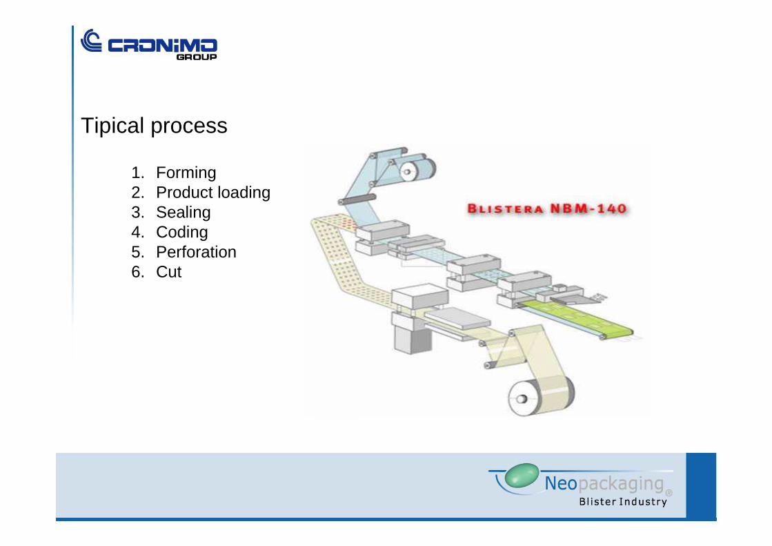
1. Forming2. Product loading3. Sealing4. Coding5. Perforation6. Cut
Tipical process

Forming materials
.- Thermoforming:
Single layer: PVCMultilayer: PVC + PVdC
PVC + PCTFE (Aclar)
Coldforming:Multilayer:
Cold Forming Foil
Material selection criteria. Product been packed.Enviroment.Marketing and sales.Costs.Available equipment.

Termo formable materials: Thermo plastic polimers PVC / PVDC / ACLAR®
Cristalline structureAmorfus structure
Heat forming
Definition: union of hundreds of thousands of small molecules“monómers” that form huge chains.
PVC (PolyVinyl Chloride)
.- It is the most widely used due to its cost/ protection ratio.
.- Its the material with the least protection.
.- It is used as the base for the rest of muti layers including Alu-Alu.
.- The blistering process is the most standard.

PVC + PVdC (PolyVinyl DiChloride )
.- It is a two-layer material with PVC as a base, with al ayer of PVdC.
.- Depending on the thickness of the PVdC (from 60 g/m2) low to mediumprotection is obtained.
.- Special care in design and construction of tooling. Heating plates to be lined with non-stick surface
.- Toxic and corrosive gases (HCl) are produced during heating.
.- As two materials are involved, different temperatures are to be chosen in each side of the heating plates.
.- Forming plug-assist is recomended.

PVC + PCTFE (Policlorotrifluoretileno – Aclar)
.- It is a two layer material with PVC as base and an adittional layer of Aclar.
.- Depending on the thickness of the Aclar layer (from 15 microns) medium tohigh protection is achived.
.- Special care in design and construction of tooling. Heating plates to be linedwith non-stick surface.
.- As two materials are involved, different temperatures are to be chosen in each side of the heating plates .
.- Forming plug-assist is recomended.

Contact
Tunnel
Heating plates
Heating coils
Thermoforming
Thermoplastics The temperature is raised to anable forming

1 2
3 4
Transitory deformation
Permanent deformation
T E Molecular movility
T E Molecular movility
Thermoforming
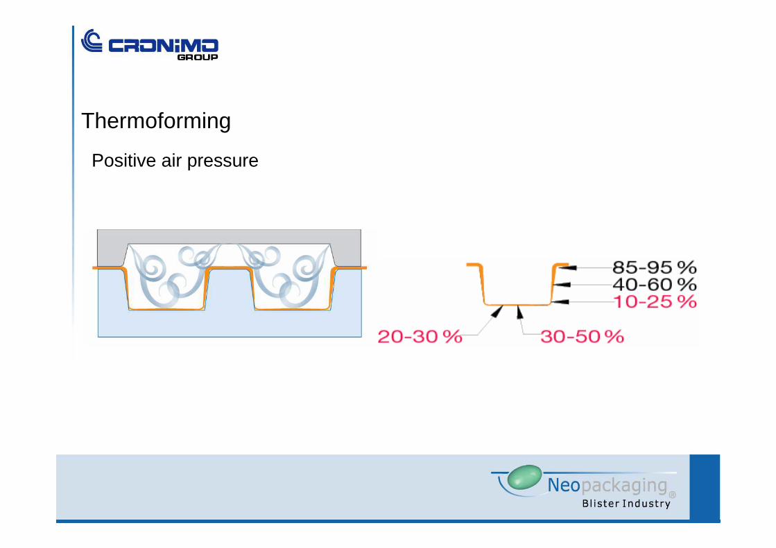
Positive air pressure
Thermoforming
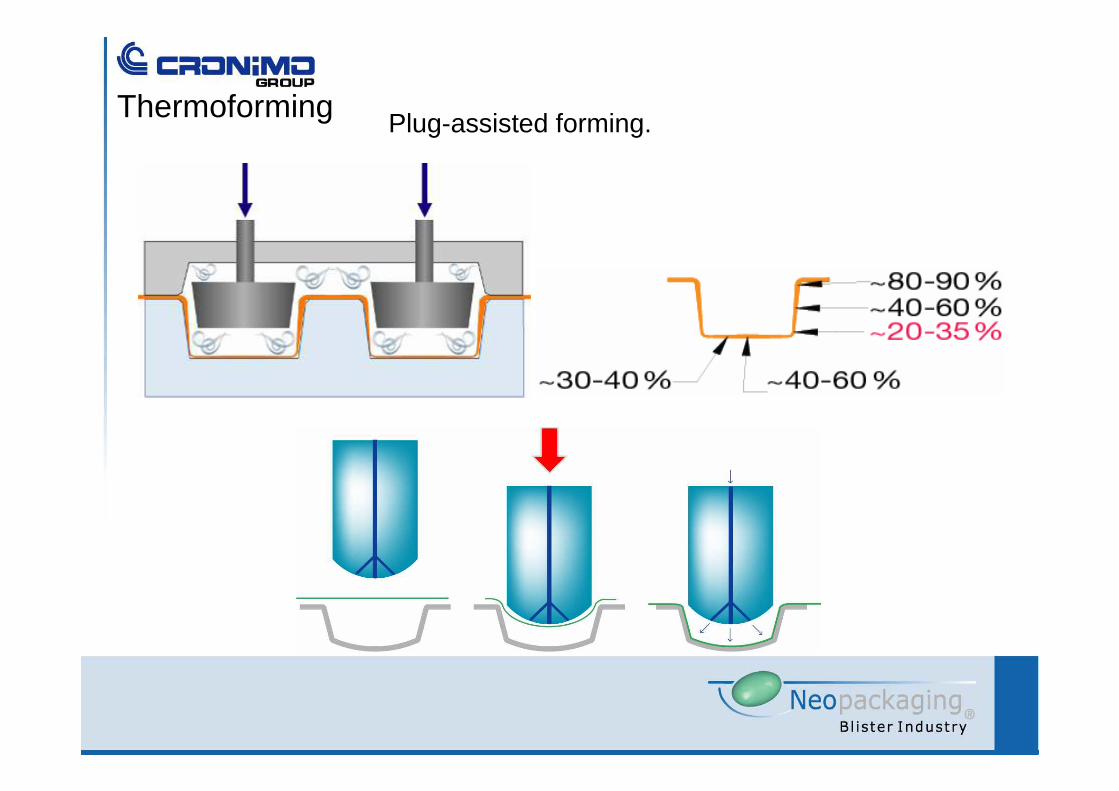
Plug-assisted forming.Thermoforming
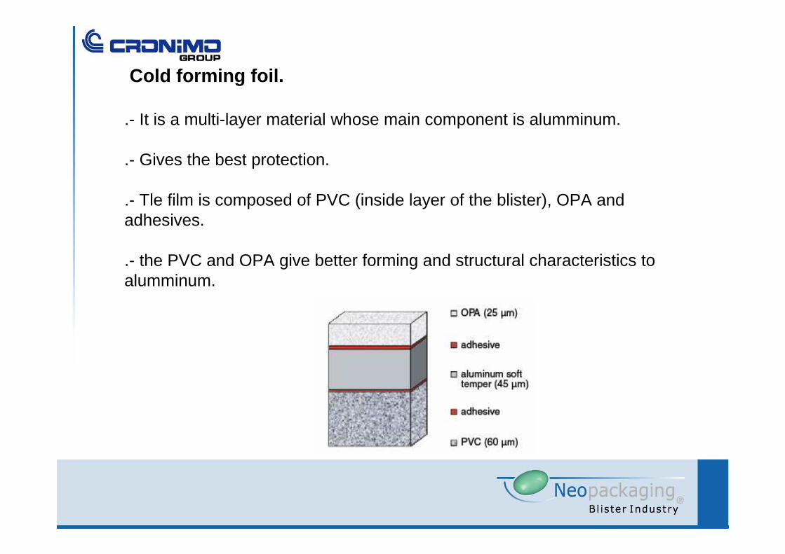
Cold forming foil.
.- It is a multi-layer material whose main component is alumminum.
.- Gives the best protection.
.- Tle film is composed of PVC (inside layer of the blister), OPA andadhesives.
.- the PVC and OPA give better forming and structural characteristics toalumminum.

Cold forming
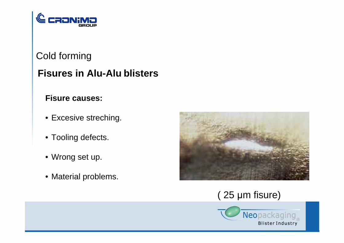
Fisures in Alu-Alu blisters
Fisure causes:
• Excesive streching.
• Tooling defects.
• Wrong set up.
• Material problems.
( 25 µm fisure)
Cold forming
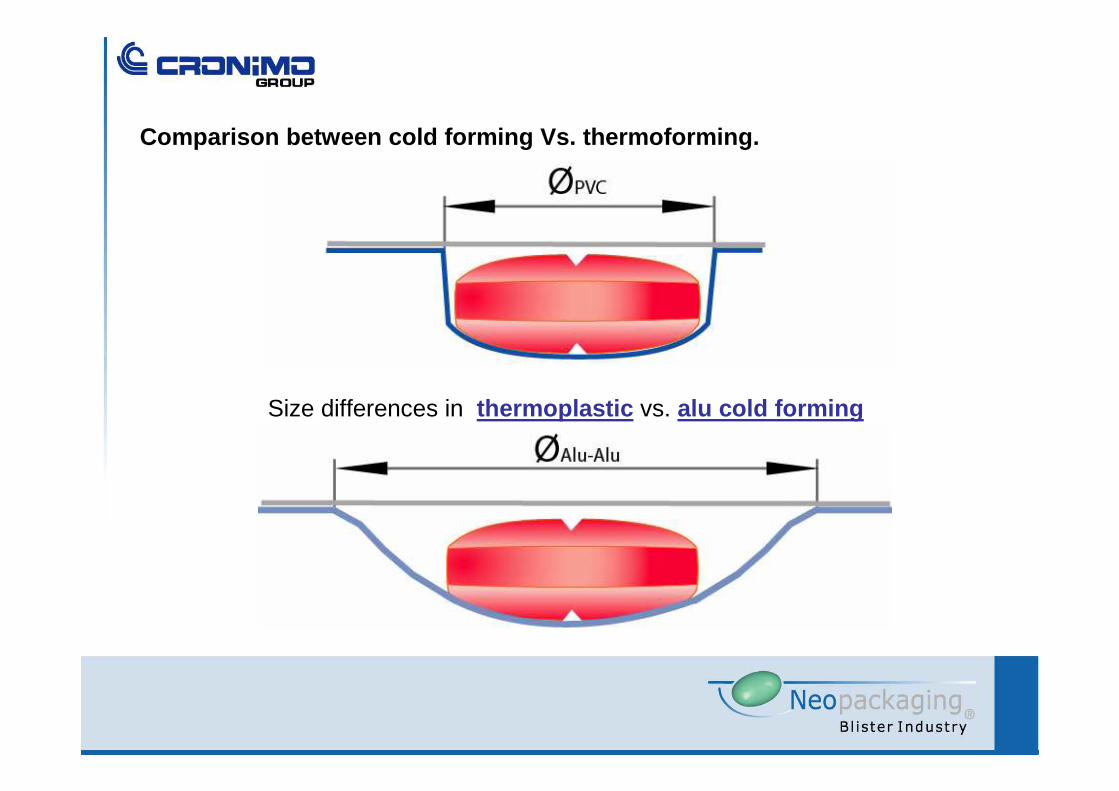
Size differences in thermoplastic vs. alu cold forming
Comparison between cold forming Vs. thermoforming.

Comparing cold forming Vs. Thermoforming.
.- Less efficient process.
.- Bigger alveoluses→ Bigger blisters → Less blister per cycle.→ less tablets per blister.
.- More complex forming means less speed.
.- Need to have microfisures detection hardware
.- More complex loading → Manual loading is slow and ineficient.→ More expensive mechanical loading devises.
.- No visual inspection can be done once the blister is sealed.
.- Blister fragility.

To be considered :1. Batch size2. Type of product / characteristics3. Blister design/ geometry / graphics4. Type of barrier (PVC, Aclar®, Alu Alu)5. Powder / aspiration
Alternatives:1. Manual feeding2. Semi-automatic feeder3. Universal automatic feeder4. Dedicated automatic feeder
Blisters
Product feedidng

• Manual
manifold
Vacuum
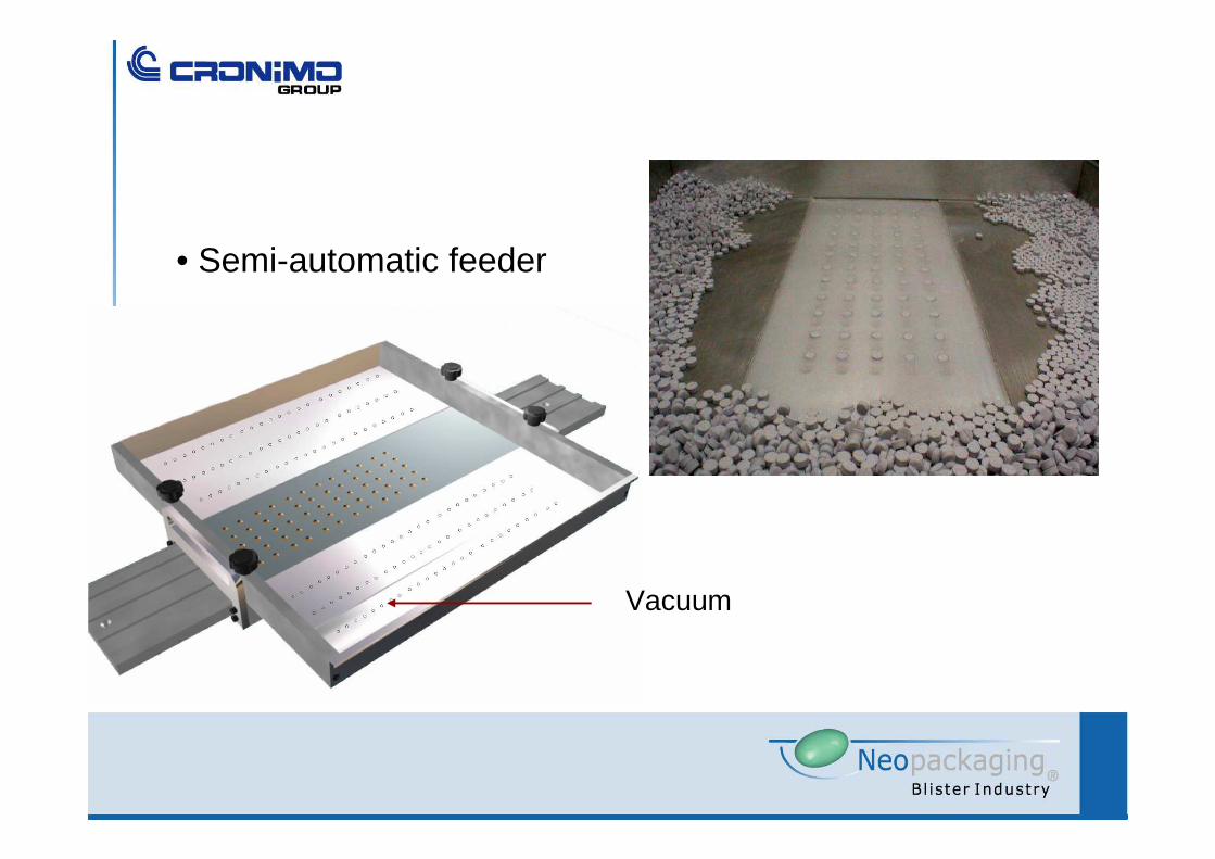
• Semi-automatic feeder
Vacuum
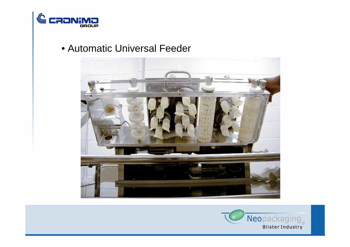
• Automatic Universal Feeder
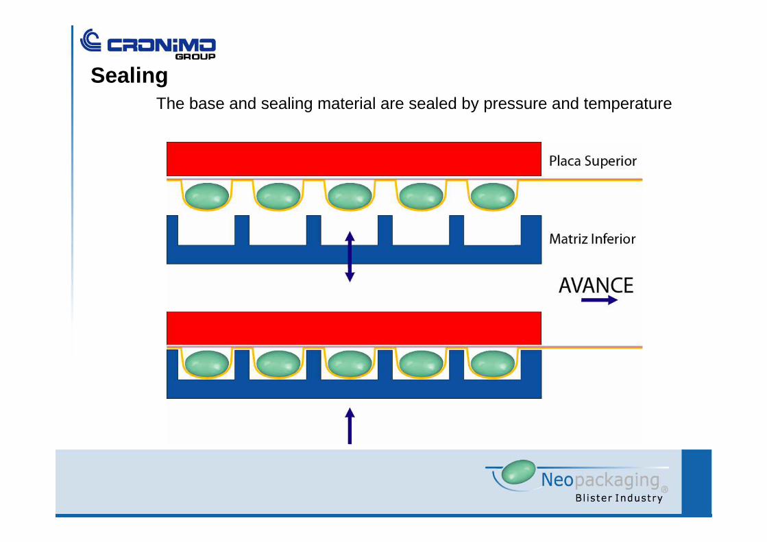
SealingThe base and sealing material are sealed by pressure and temperature
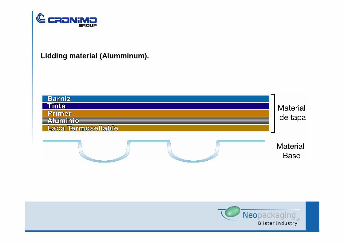
Lidding material (Alumminum).
Thermosealing laquersThe functional characteristics of the the lacquer is to act as a thermosealingagent between the PVC or PVDC and the lidding material.
It is a critical component as it has to assure:
- Intimate sealing between PVC and alumminum(hermeticity)
- Sealing at relatibly low temperatures(inks, barnishes and product degradation)
- Dimensional stability(deformation)
- Dstability in time of the union(aging)
- Inocuity(Tablet contamination from solvents or decomposition of polimers into free monomers)
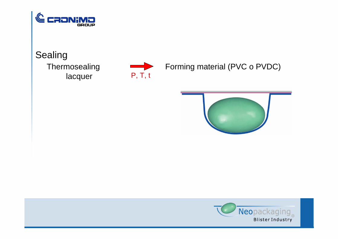
Thermosealinglacquer P, T, t
SealingForming material (PVC o PVDC)

Coding

One way Two way
Perforation
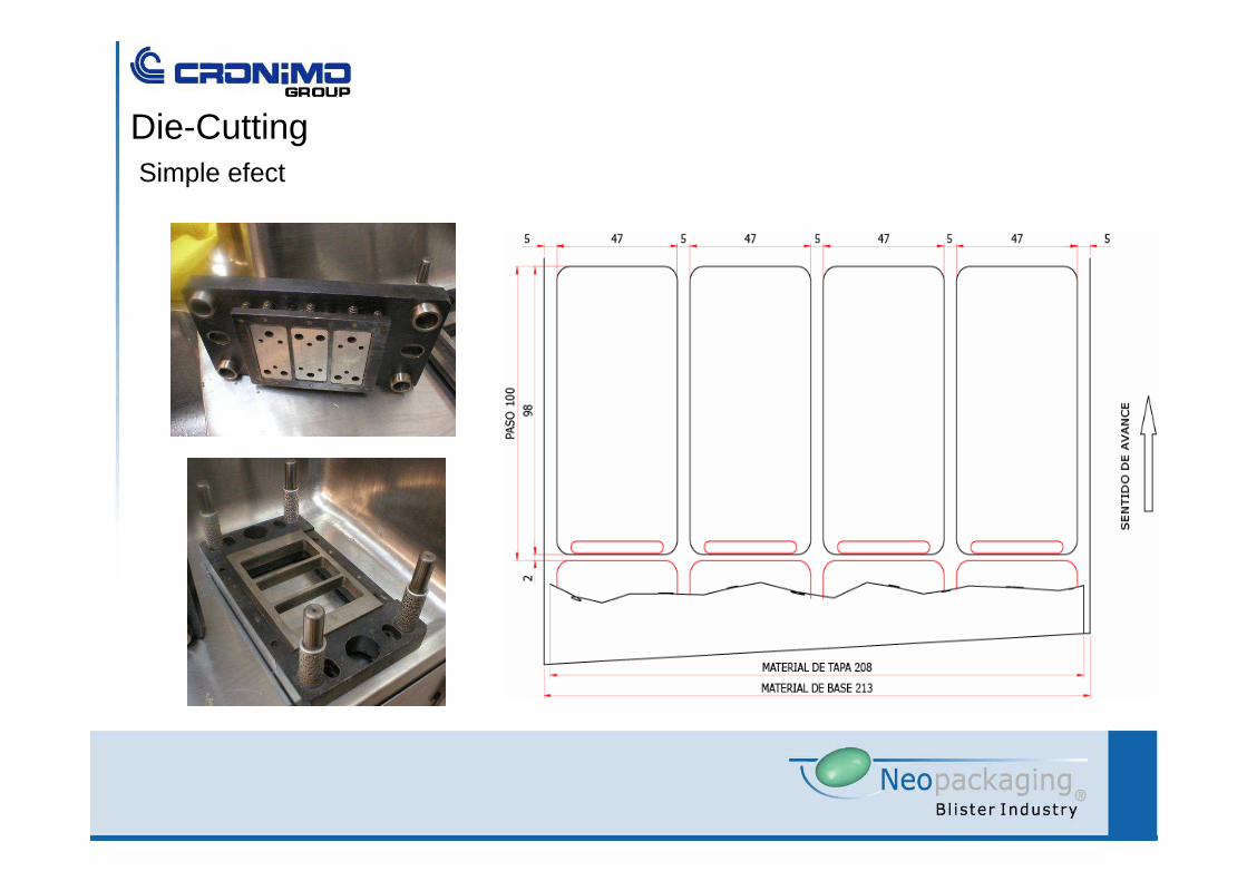
Die-CuttingSimple efect
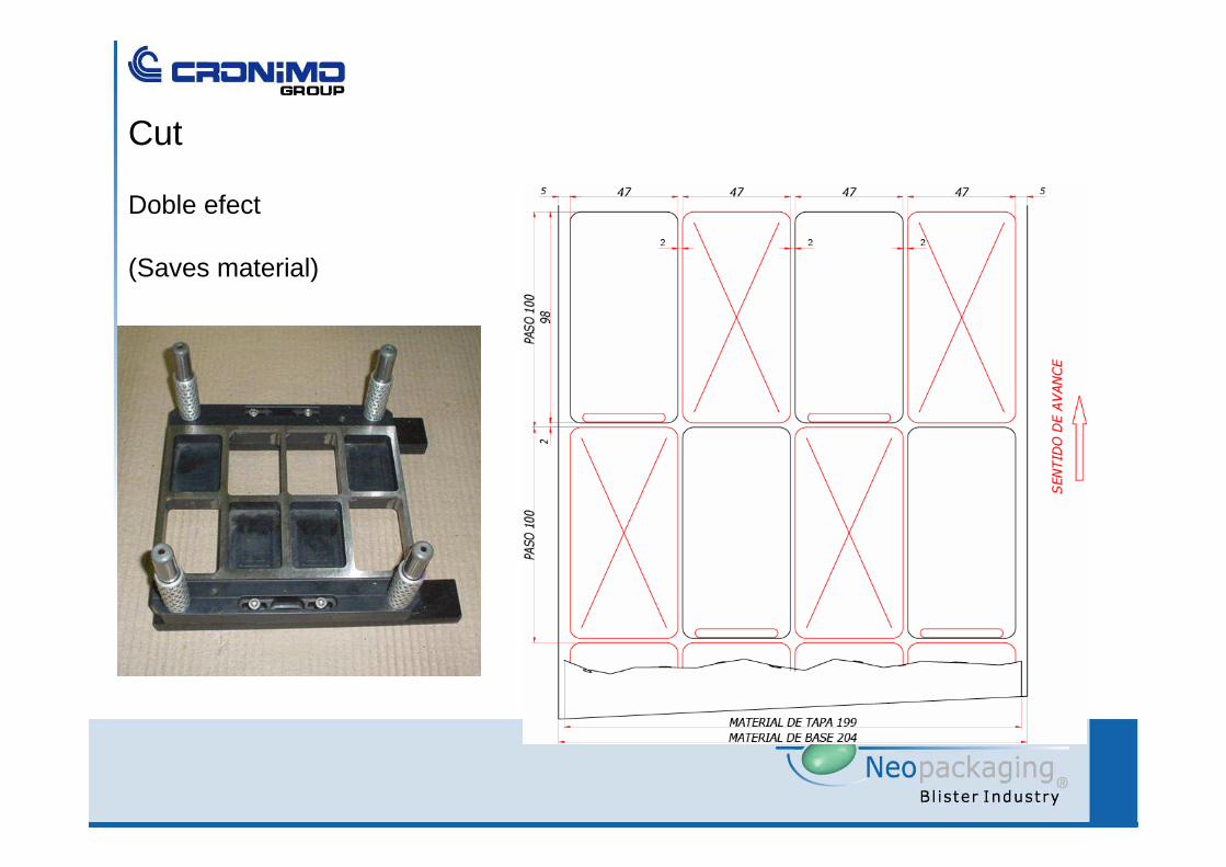
Cut
Doble efect
(Saves material)
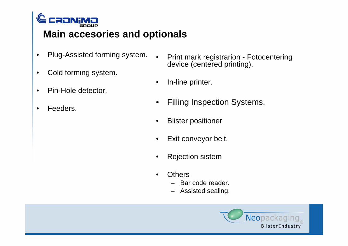
Main accesories and optionals
• Plug-Assisted forming system.
• Cold forming system.
• Pin-Hole detector.
• Feeders.
• Print mark registrarion - Fotocenteringdevice (centered printing).
• In-line printer.
• Filling Inspection Systems.
• Blister positioner
• Exit conveyor belt.
• Rejection sistem
• Others– Bar code reader.– Assisted sealing.

The blister uses lidding material withcenterd printing.Ej: Monodose
Medical samples.
Etc.
Photo centering – Mark reader and step corrector

Photo centering – Mark reader and step corrector
SISTEMA DE AVANCE CON
CORRECTOR
SENSOR DE CONTRASTE
TACO
HAZ DE LUZ
start: Light ray inside the mark.
1.- Step is longer than the nominal for thelidding material.
Mark moves downward.
2.- moves forward with the same step: thelight is outside the mark.
Sensor sends a signal: the corrector isactivated.
3.- The step corrector shortens the advancedistance.
The markreturns to the original position.
La impresión constantemente se desplaza respecto del corte, dentro de valores determinados.
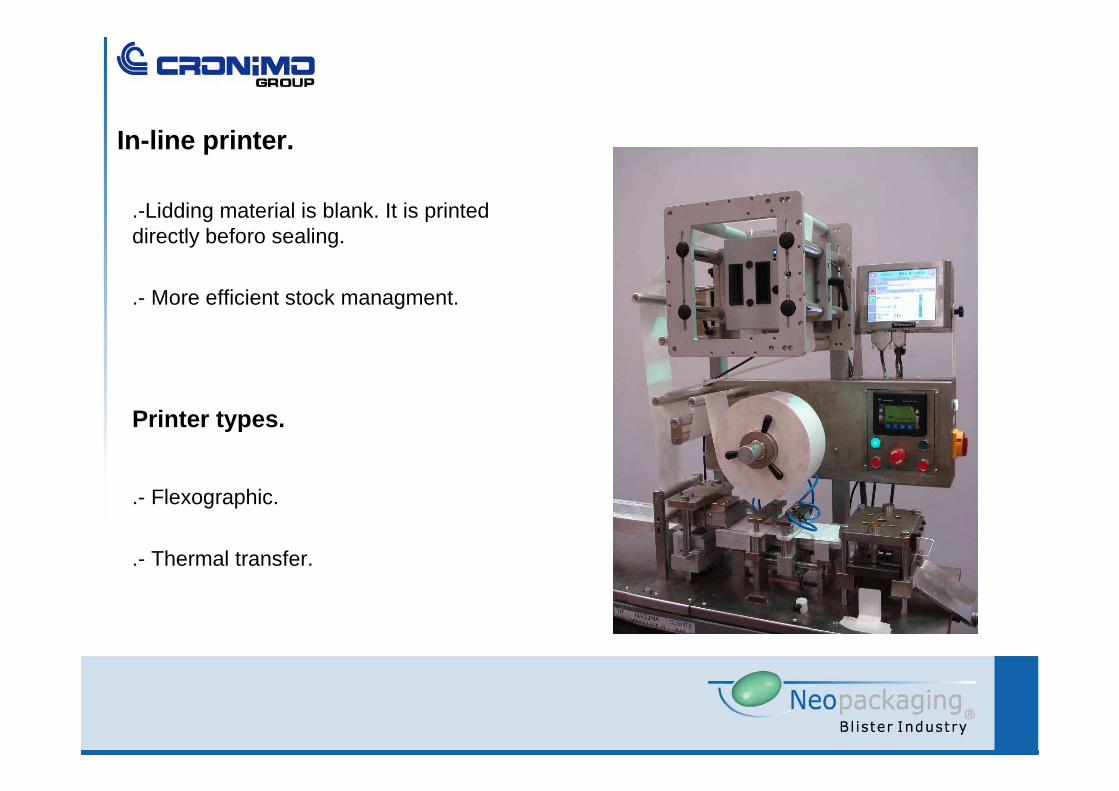
.-Lidding material is blank. It is printeddirectly beforo sealing.
.- More efficient stock managment.
In-line printer.
.- Flexographic.
.- Thermal transfer.
Printer types.
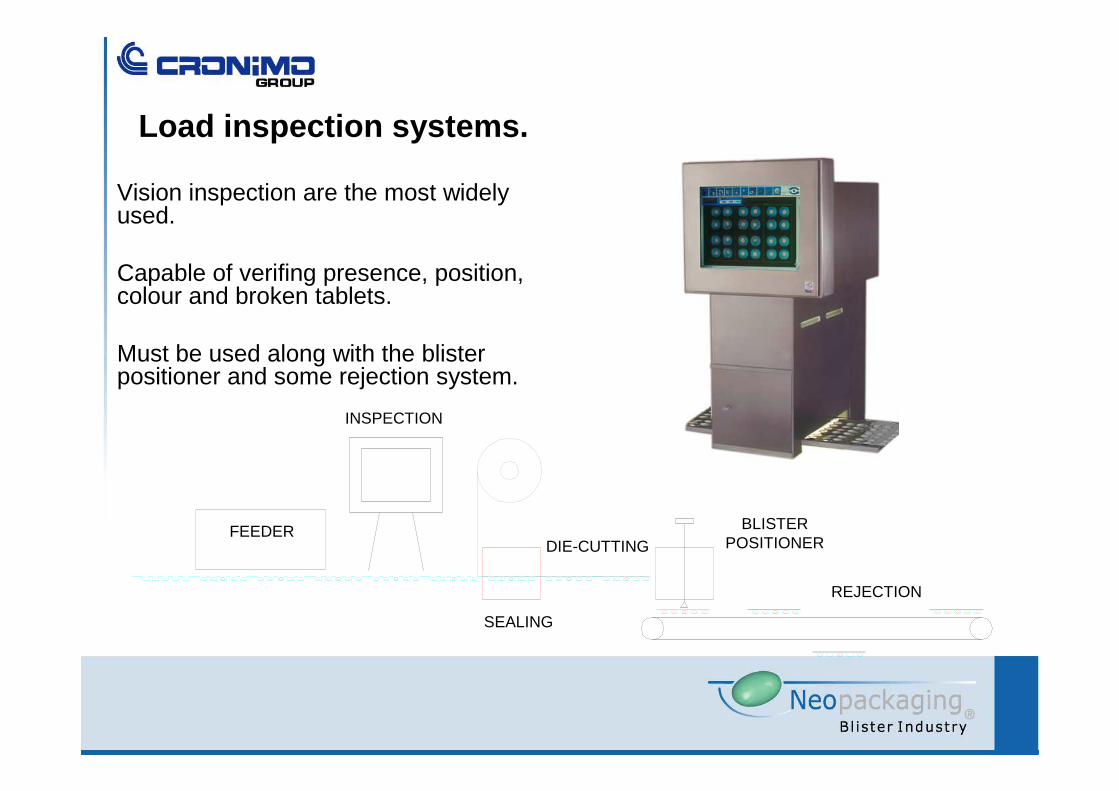
Load inspection systems.
Vision inspection are the most widelyused.
Capable of verifing presence, position, colour and broken tablets.
Must be used along with the blister positioner and some rejection system.
FEEDER
INSPECTION
SEALING
REJECTION
BLISTER POSITIONERDIE-CUTTING
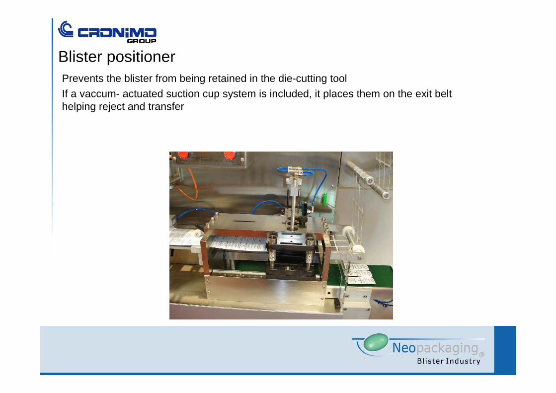
Blister positionerPrevents the blister from being retained in the die-cutting tool
If a vaccum- actuated suction cup system is included, it places them on the exit belthelping reject and transfer

Discard.
• Complete step– Discards all the blister in 1 step.
• Individual– Discards only the faulty blister.
• Pick and Place– The concept is not to reject the bad ones but to take the good ones at the end of
the operation.
• Discard control.– Sensors verify that discard is done.
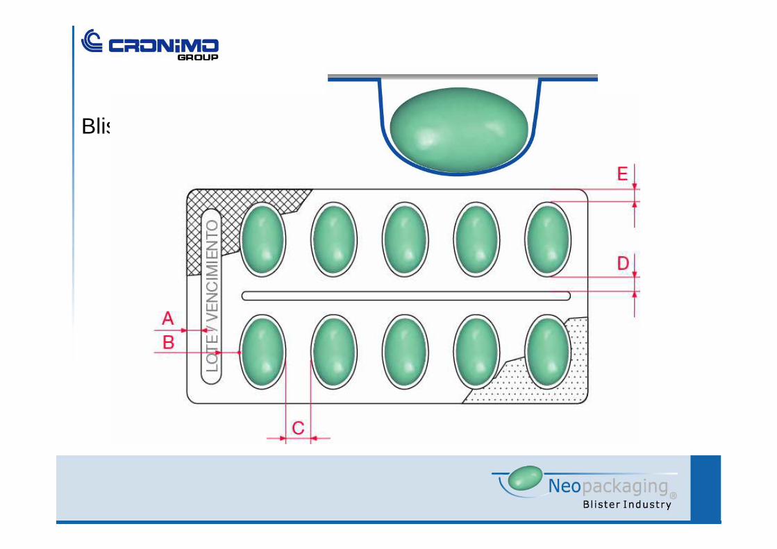
Blister design


