36
BLUETOOTH SMART MODULE CONFIGURATION GUIDE Tuesday, 2 September 2014 Version 3.6
BLUETOOTH SMART MODULE
CONFIGURATION GUIDE
Tuesday, 2 September 2014
Version 3.6

Copyright © 2001-2014 Bluegiga Technologies Page of 2 36
Copyright © 2001 - 2014 Bluegiga Technologies
Bluegiga Technologies reserves the right to alter the hardware, software, and/or specifications detailed herein atany time without notice, and does not make any commitment to update the information contained herein.Bluegiga Technologies assumes no responsibility for any errors which may appear in this manual. BluegigaTechnologies' products are not authorized for use as critical components in life support devices or systems.
Bluegiga Access Server, Access Point, APx4, AX4, BSM, iWRAP, BGScript and WRAP THOR are trademarksof Bluegiga Technologies.
The trademark and logo are registered trademarks and are owned by the Bluetooth SIG, Inc.Bluetooth
ARM and ARM9 are trademarks of ARM Ltd.
Linux is a trademark of Linus Torvalds.
All other trademarks listed herein belong to their respective owners.
Copyright © 2001-2014 Bluegiga Technologies Page of 3 36
Table of Contents
1 Version History ________________________________________________________________________ 42 Introduction ___________________________________________________________________________ 53 Project Configuration File ________________________________________________________________ 6
3.1 <device> _________________________________________________________________________ 63.2 <gatt> ___________________________________________________________________________ 63.3 <hardware> _______________________________________________________________________ 83.4 <config> __________________________________________________________________________ 83.5 <script> __________________________________________________________________________ 83.6 <usb_main> _______________________________________________________________________ 83.7 <image> _________________________________________________________________________ 93.8 <ota> ____________________________________________________________________________ 93.9 <boot> __________________________________________________________________________ 103.10 Examples ________________________________________________________________________ 11
4 Hardware Configuration File (hardware.xml) _________________________________________________ 124.1 <sleeposc> ______________________________________________________________________ 124.2 <script> _________________________________________________________________________ 134.3 <slow_clock> _____________________________________________________________________ 134.4 <lock_debug> ____________________________________________________________________ 144.5 <sleep> _________________________________________________________________________ 144.6 <wakeup_pin> ____________________________________________________________________ 164.7 <host_wakeup_pin> _______________________________________________________________ 184.8 <txpower> _______________________________________________________________________ 194.9 <pmux> _________________________________________________________________________ 204.10 <port> __________________________________________________________________________ 214.11 <usb> __________________________________________________________________________ 224.12 <usart> _________________________________________________________________________ 234.13 <timer_ticks> _____________________________________________________________________ 264.14 <timer> _________________________________________________________________________ 274.15 <otaboot> _______________________________________________________________________ 294.16 Endpoints _______________________________________________________________________ 304.17 Examples ________________________________________________________________________ 30
5 Application Configuration File (config.xml) __________________________________________________ 315.1 <connections> ____________________________________________________________________ 315.2 <defrag> ________________________________________________________________________ 315.3 <manual_confirm> _________________________________________________________________ 325.4 <script_timeout> __________________________________________________________________ 325.5 <throughput> _____________________________________________________________________ 335.6 <passkey> _______________________________________________________________________ 335.7 <user_data> _____________________________________________________________________ 345.8 <dfu> ___________________________________________________________________________ 345.9 Examples ________________________________________________________________________ 34
Copyright © 2001-2014 Bluegiga Technologies Page of 4 36
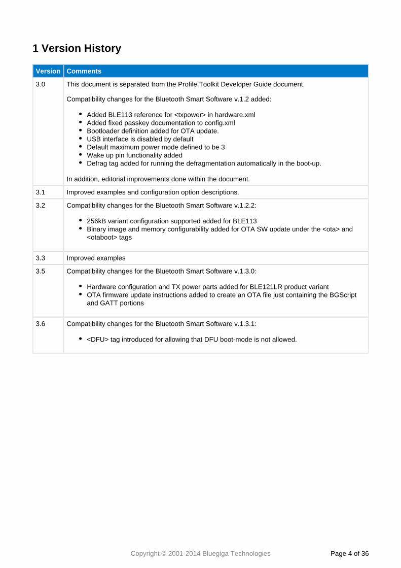
1 Version History
Version Comments
3.0 This document is separated from the Profile Toolkit Developer Guide document.
Compatibility changes for the Bluetooth Smart Software v.1.2 added:
Added BLE113 reference for <txpower> in hardware.xmlAdded fixed passkey documentation to config.xmlBootloader definition added for OTA update.USB interface is disabled by defaultDefault maximum power mode defined to be 3Wake up pin functionality addedDefrag tag added for running the defragmentation automatically in the boot-up.
In addition, editorial improvements done within the document.
3.1 Improved examples and configuration option descriptions.
3.2 Compatibility changes for the Bluetooth Smart Software v.1.2.2:
256kB variant configuration supported added for BLE113Binary image and memory configurability added for OTA SW update under the <ota> and<otaboot> tags
3.3 Improved examples
3.5 Compatibility changes for the Bluetooth Smart Software v.1.3.0:
Hardware configuration and TX power parts added for BLE121LR product variantOTA firmware update instructions added to create an OTA file just containing the BGScriptand GATT portions
3.6 Compatibility changes for the Bluetooth Smart Software v.1.3.1:
<DFU> tag introduced for allowing that DFU boot-mode is not allowed.

Copyright © 2001-2014 Bluegiga Technologies Page of 5 36
2 Introduction
The Smart configuration guide instructs you how to how to create a project file for your application andBluetoothhow to configure your Smart Modules hardware and application configuration settings.Bluetooth
Copyright © 2001-2014 Bluegiga Technologies Page of 6 36
3 Project Configuration File
The project file (typically is the file that describes all the components included inproject.bgproj or project.xml)a Bluetooth Smart software and hardware project. Typically these files are name something like this:
hardware.xml - Hardware configuration filegatt.xml - GATT database fileconfig.xml - Optional application configuration filescript.bgs - Optional BGScript application source codecdc.xml - Optional USB descriptor file (not used with BLE113, BLE121LR)
The project file also defines other features of the project like the hardware version (BLE112, BLE113, andBLE121LR), firmware output files and selected bootloader.
The project file itself is a simple XML file with only few tags on it, which are described below.
If the project file is named as (or any other file with a extension), then theproject.bgproj .bgprojBluegiga application will automatically recognize it in the Windows Explorer interface andBLE Updateallow you to easily open, compile, and flash the project to a module using the CC debugger.
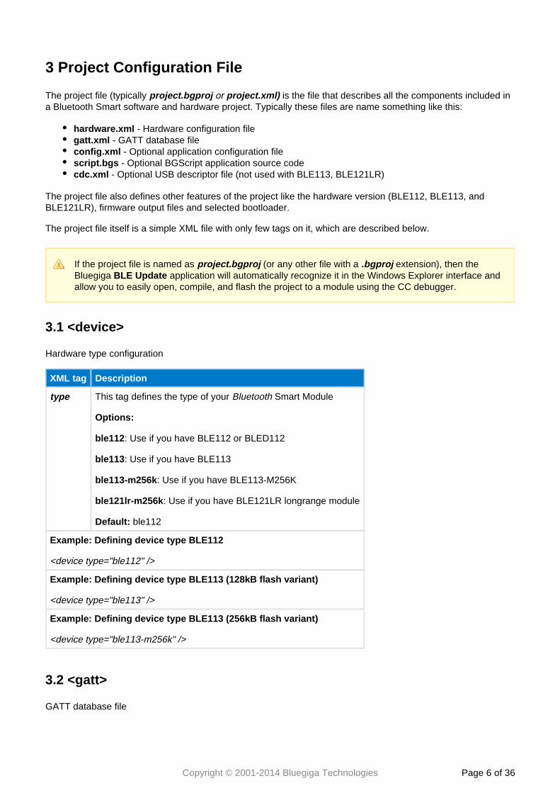
3.1 <device>
Hardware type configuration
XML tag Description
type This tag defines the type of your Smart ModuleBluetooth
Options:
ble112: Use if you have BLE112 or BLED112
ble113: Use if you have BLE113
ble113-m256k: Use if you have BLE113-M256K
ble121lr-m256k: Use if you have BLE121LR longrange module
Default: ble112
Example: Defining device type BLE112
<device type="ble112" />
Example: Defining device type BLE113 (128kB flash variant)
<device type="ble113" />
Example: Defining device type BLE113 (256kB flash variant)
<device type="ble113-m256k" />
3.2 <gatt>
GATT database file

Copyright © 2001-2014 Bluegiga Technologies Page of 7 36
XML tag Description
in This tag points to the XML file that contains the GATT database structure.
Example: Defining the GATT database file
<gatt in="gatt.xml" />
Copyright © 2001-2014 Bluegiga Technologies Page of 8 36
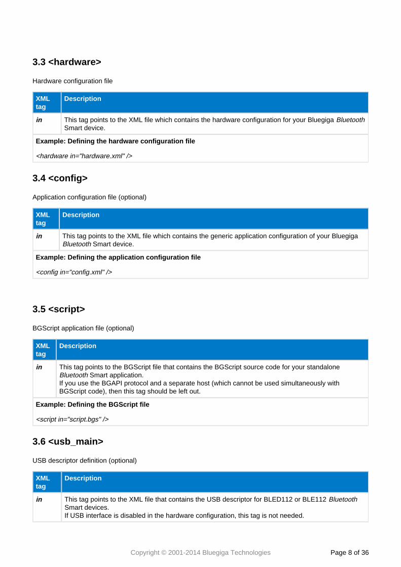
3.3 <hardware>
Hardware configuration file
XMLtag
Description
in This tag points to the XML file which contains the hardware configuration for your Bluegiga BluetoothSmart device.
Example: Defining the hardware configuration file
<hardware in="hardware.xml" />
3.4 <config>
Application configuration file (optional)
XMLtag
Description
in This tag points to the XML file which contains the generic application configuration of your Bluegiga Smart device.Bluetooth
Example: Defining the application configuration file
<config in="config.xml" />
3.5 <script>
BGScript application file (optional)
XMLtag
Description
in This tag points to the BGScript file that contains the BGScript source code for your standalone Smart application.Bluetooth
If you use the BGAPI protocol and a separate host (which cannot be used simultaneously withBGScript code), then this tag should be left out.
Example: Defining the BGScript file
<script in="script.bgs" />
3.6 <usb_main>
USB descriptor definition (optional)
XMLtag
Description
in This tag points to the XML file that contains the USB descriptor for BLED112 or BLE112 BluetoothSmart devices.If USB interface is disabled in the hardware configuration, this tag is not needed.
Copyright © 2001-2014 Bluegiga Technologies Page of 9 36
XMLtag
Description
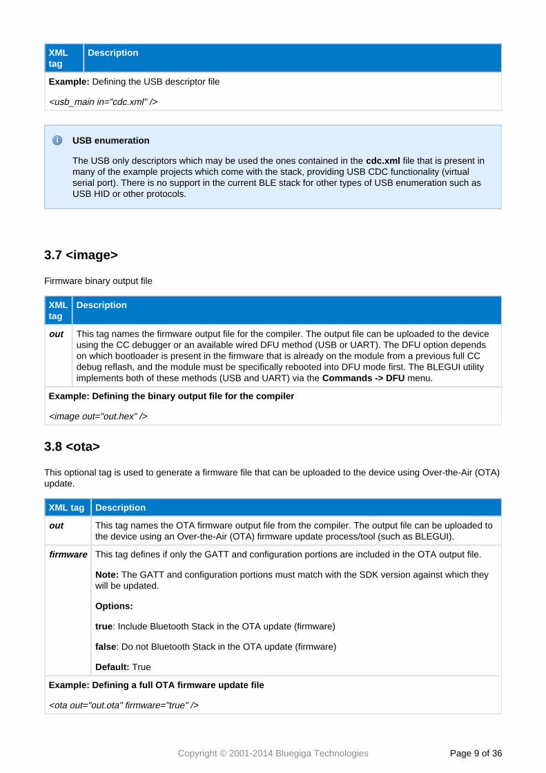
Example: Defining the USB descriptor file
<usb_main in="cdc.xml" />
USB enumeration
The USB only descriptors which may be used the ones contained in the file that is present incdc.xmlmany of the example projects which come with the stack, providing USB CDC functionality (virtualserial port). There is no support in the current BLE stack for other types of USB enumeration such asUSB HID or other protocols.
3.7 <image>
Firmware binary output file
XMLtag
Description
out This tag names the firmware output file for the compiler. The output file can be uploaded to the deviceusing the CC debugger or an available wired DFU method (USB or UART). The DFU option dependson which bootloader is present in the firmware that is already on the module from a previous full CCdebug reflash, and the module must be specifically rebooted into DFU mode first. The BLEGUI utilityimplements both of these methods (USB and UART) via the menu.Commands -> DFU
Example: Defining the binary output file for the compiler
<image out="out.hex" />
3.8 <ota>
This optional tag is used to generate a firmware file that can be uploaded to the device using Over-the-Air (OTA)update.
XML tag Description
out This tag names the OTA firmware output file from the compiler. The output file can be uploaded tothe device using an Over-the-Air (OTA) firmware update process/tool (such as BLEGUI).
firmware This tag defines if only the GATT and configuration portions are included in the OTA output file.
Note: The GATT and configuration portions must match with the SDK version against which theywill be updated.
Options:
true: Include Bluetooth Stack in the OTA update (firmware)
false: Do not Bluetooth Stack in the OTA update (firmware)
Default: True
Example: Defining a full OTA firmware update file
<ota out="out.ota" firmware="true" />
Copyright © 2001-2014 Bluegiga Technologies Page of 10 36
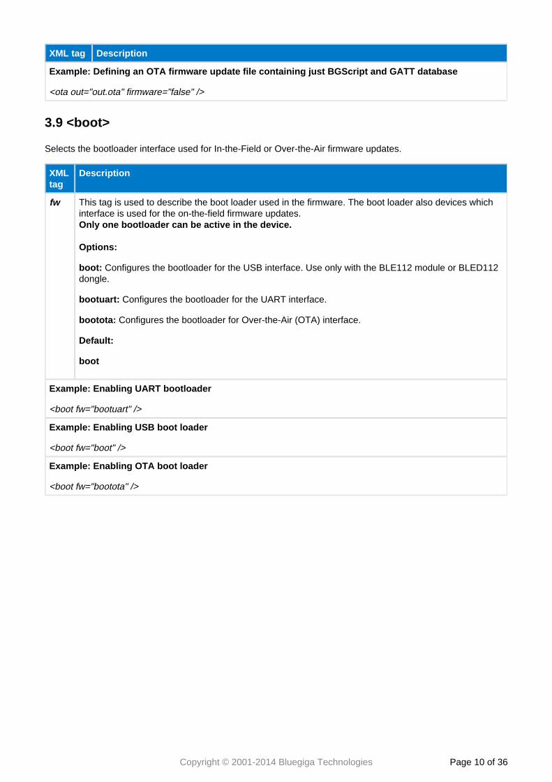
XML tag Description
Example: Defining an OTA firmware update file containing just BGScript and GATT database
<ota out="out.ota" firmware="false" />
3.9 <boot>
Selects the bootloader interface used for In-the-Field or Over-the-Air firmware updates.
XMLtag
Description
fw This tag is used to describe the boot loader used in the firmware. The boot loader also devices whichinterface is used for the on-the-field firmware updates.Only one bootloader can be active in the device.
Options:
boot: Configures the bootloader for the USB interface. Use only with the BLE112 module or BLED112dongle.
bootuart: Configures the bootloader for the UART interface.
bootota: Configures the bootloader for Over-the-Air (OTA) interface.
Default:
boot
Example: Enabling UART bootloader
<boot fw="bootuart" />
Example: Enabling USB boot loader
<boot fw="boot" />
Example: Enabling OTA boot loader
<boot fw="bootota" />
Copyright © 2001-2014 Bluegiga Technologies Page of 11 36
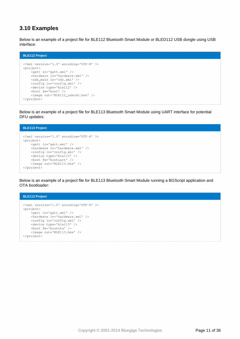
3.10 Examples
Below is an example of a project file for BLE112 Bluetooth Smart Module or BLED112 USB dongle using USBinterface:
BLE112 Project
<?xml version="1.0" encoding="UTF-8" ?><project> <gatt in="gatt.xml" /> <hardware in="hardware.xml" /> <usb_main in="cdc.xml" /> <config in="config.xml" /> <device type="ble112" /> <boot fw="boot" /> <image out="BLE112_usbcdc.hex" /></project>
Below is an example of a project file for BLE113 Bluetooth Smart Module using UART interface for potentialDFU updates:
BLE113 Project
<?xml version="1.0" encoding="UTF-8" ?><project> <gatt in="gatt.xml" /> <hardware in="hardware.xml" /> <config in="config.xml" /> <device type="ble113" /> <boot fw="bootuart" /> <image out="BLE113.hex" /></project>
Below is an example of a project file for BLE113 Bluetooth Smart Module running a BGScript application andOTA bootloader:
BLE113 Project
<?xml version="1.0" encoding="UTF-8" ?><project> <gatt in="gatt.xml" /> <hardware in="hardware.xml" /> <config in="config.xml" /> <device type="ble113" /> <boot fw="bootota" /> <image out="BLE113.hex" /></project>
Copyright © 2001-2014 Bluegiga Technologies Page of 12 36
4 Hardware Configuration File (hardware.xml)
The hardware configuration file is used to configure the hardware features such as TX power, UART, SPI,hardware timers, and GPIO settings of your Bluegiga Smart device.Bluetooth
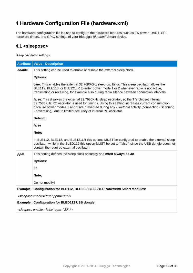
4.1 <sleeposc>
Sleep oscillator settings
Attribute Value - Description
enable This setting can be used to enable or disable the external sleep clock.
Options:
true: This enables the external 32.7680KHz sleep oscillator. This sleep oscillator allows theBLE112, BLE113, or BLE121LR to enter power mode 1 or 2 whenever radio is not active,transmitting or receiving, for example also during radio silence between connection intervals.
false: This disables the external 32.7680KHz sleep oscillator, so the TI's chipset internal32.7530KHz RC oscillator is used for timings. Using this setting increases current consumptionbecause power modes 1 and 2 are prevented during any activity (connection - scanningBluetooth- advertising), due to limited accuracy of internal RC oscillator.
Default:
false
Note:
In BLE112, BLE113, and BLE121LR this options MUST be configured to enable the external sleeposcillator, while in the BLED112 this option MUST be set to "false", since the USB dongle does notcontain the required external oscillator.
ppm This setting defines the sleep clock accuracy and .must always be 30
Options:
30
Note:
Do not modify!
Example : Configuration for BLE112, BLE113, BLE121LR Smart Modules: Bluetooth
<sleeposc enable="true" ppm="30" />
Example : Configuration for BLED112 USB dongle:
<sleeposc enable="false" ppm="30" />
Copyright © 2001-2014 Bluegiga Technologies Page of 13 36
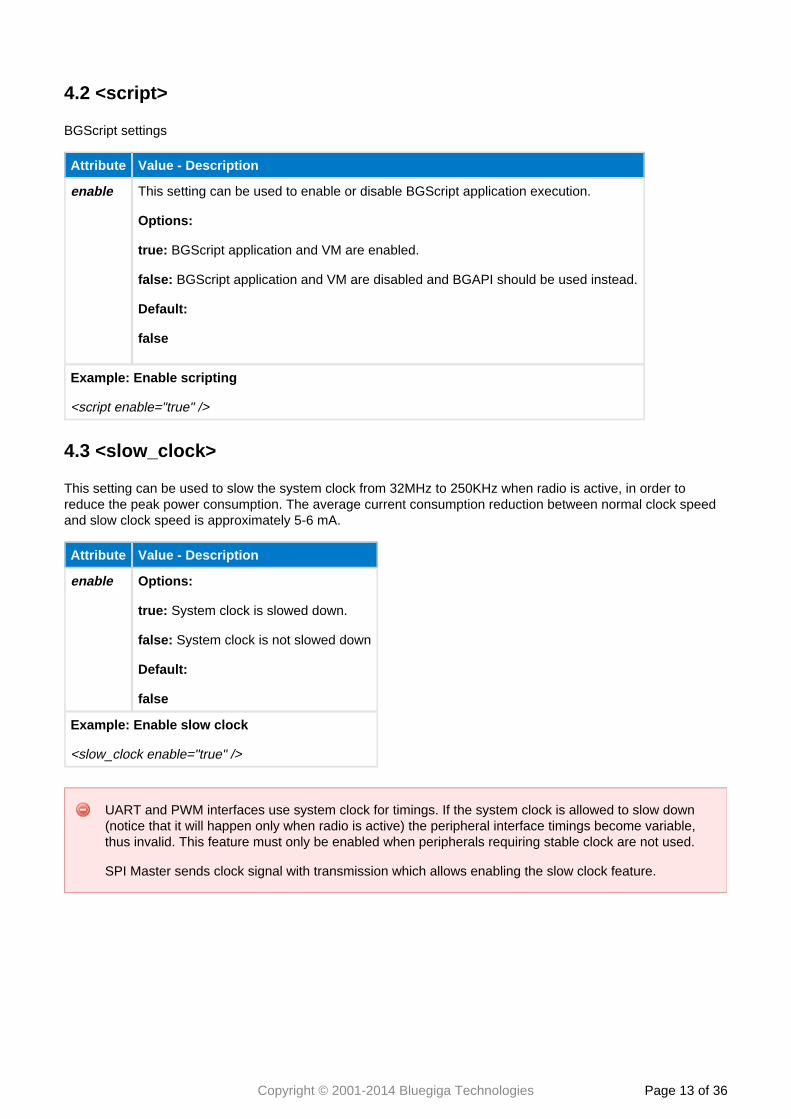
4.2 <script>
BGScript settings
Attribute Value - Description
enable This setting can be used to enable or disable BGScript application execution.
Options:
true: BGScript application and VM are enabled.
false: BGScript application and VM are disabled and BGAPI should be used instead.
Default:
false
Example: Enable scripting
<script enable="true" />
4.3 <slow_clock>
This setting can be used to slow the system clock from 32MHz to 250KHz when radio is active, in order toreduce the peak power consumption. The average current consumption reduction between normal clock speedand slow clock speed is approximately 5-6 mA.
Attribute Value - Description
enable Options:
true: System clock is slowed down.
false: System clock is not slowed down
Default:
false
Example: Enable slow clock
<slow_clock enable="true" />
UART and PWM interfaces use system clock for timings. If the system clock is allowed to slow down(notice that it will happen only when radio is active) the peripheral interface timings become variable,thus invalid. This feature must only be enabled when peripherals requiring stable clock are not used.
SPI Master sends clock signal with transmission which allows enabling the slow clock feature.
Copyright © 2001-2014 Bluegiga Technologies Page of 14 36
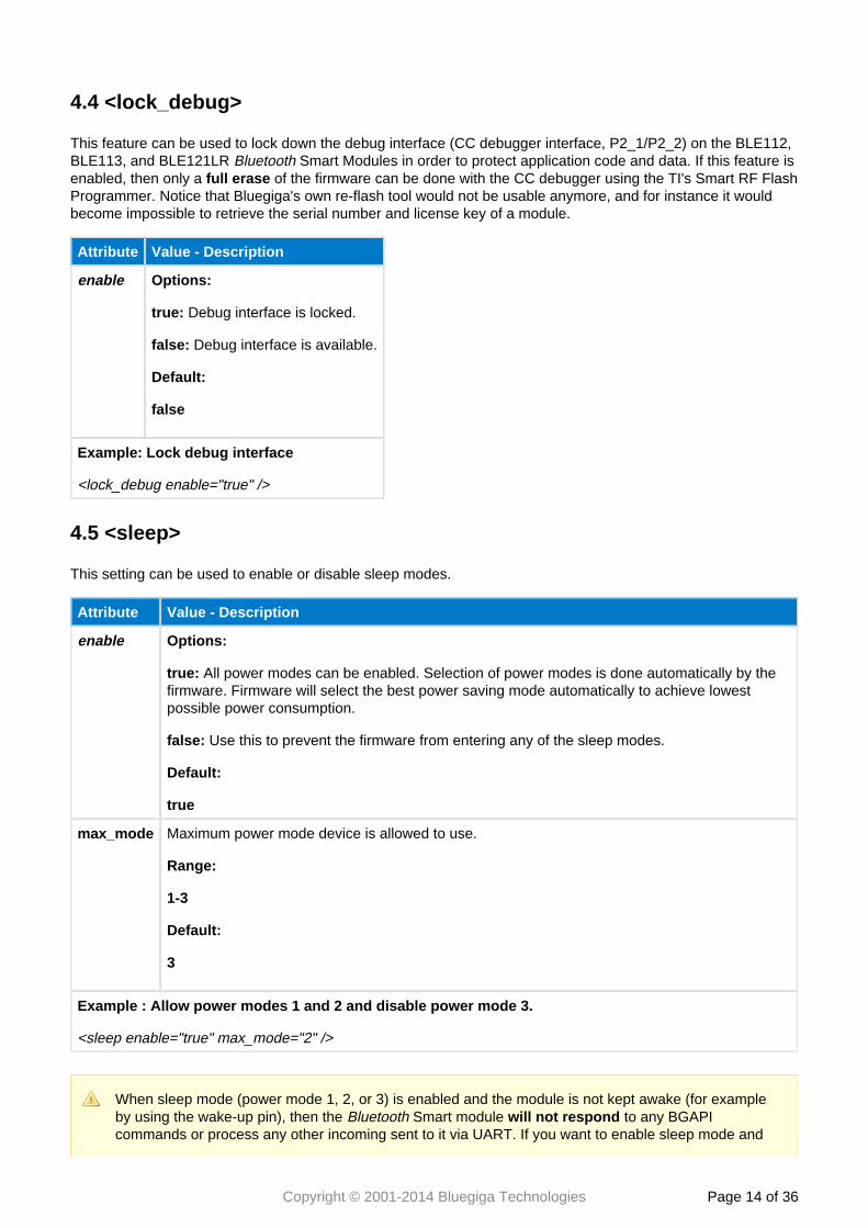
4.4 <lock_debug>
This feature can be used to lock down the debug interface (CC debugger interface, P2_1/P2_2) on the BLE112,BLE113, and BLE121LR Smart Modules in order to protect application code and data. If this feature isBluetoothenabled, then only a of the firmware can be done with the CC debugger using the TI's Smart RF Flashfull eraseProgrammer. Notice that Bluegiga's own re-flash tool would not be usable anymore, and for instance it wouldbecome impossible to retrieve the serial number and license key of a module.
Attribute Value - Description
enable Options:
true: Debug interface is locked.
false: Debug interface is available.
Default:
false
Example: Lock debug interface
<lock_debug enable="true" />
4.5 <sleep>
This setting can be used to enable or disable sleep modes.
Attribute Value - Description
enable Options:
true: All power modes can be enabled. Selection of power modes is done automatically by thefirmware. Firmware will select the best power saving mode automatically to achieve lowestpossible power consumption.
false: Use this to prevent the firmware from entering any of the sleep modes.
Default:
true
max_mode Maximum power mode device is allowed to use.
Range:
1-3
Default:
3
Example : Allow power modes 1 and 2 and disable power mode 3.
<sleep enable="true" max_mode="2" />
When sleep mode (power mode 1, 2, or 3) is enabled and the module is not kept awake (for exampleby using the wake-up pin), then the Smart module to any BGAPIBluetooth will not respondcommands or process any other incoming sent to it via UART. If you want to enable sleep mode and

Copyright © 2001-2014 Bluegiga Technologies Page of 15 36
use the UART interface to communicate with the module, you need to enable the wake-up pin feature(described below) and provide a wake-up signal from an external host.
Copyright © 2001-2014 Bluegiga Technologies Page of 16 36
1. 2.
3. 4.
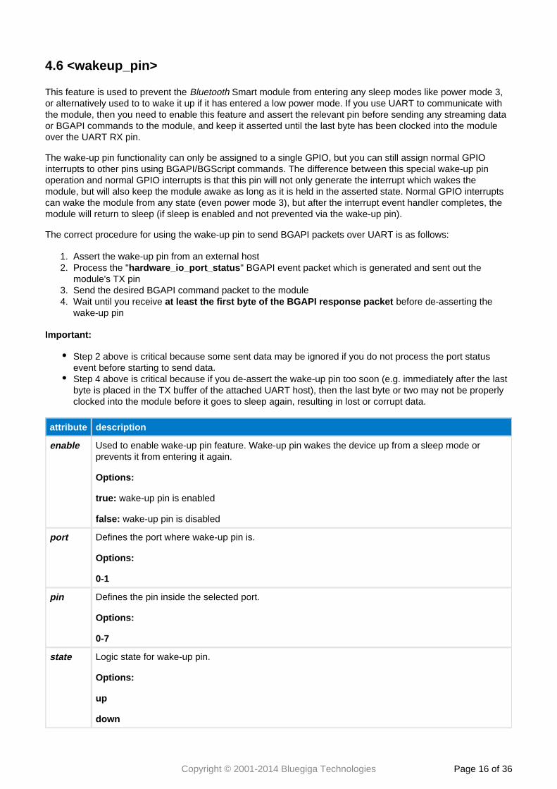
4.6 <wakeup_pin>
This feature is used to prevent the Smart module from entering any sleep modes like power mode 3,Bluetoothor alternatively used to to wake it up if it has entered a low power mode. If you use UART to communicate withthe module, then you need to enable this feature and assert the relevant pin before sending any streaming dataor BGAPI commands to the module, and keep it asserted until the last byte has been clocked into the moduleover the UART RX pin.
The wake-up pin functionality can only be assigned to a single GPIO, but you can still assign normal GPIOinterrupts to other pins using BGAPI/BGScript commands. The difference between this special wake-up pinoperation and normal GPIO interrupts is that this pin will not only generate the interrupt which wakes themodule, but will also keep the module awake as long as it is held in the asserted state. Normal GPIO interruptscan wake the module from any state (even power mode 3), but after the interrupt event handler completes, themodule will return to sleep (if sleep is enabled and not prevented via the wake-up pin).
The correct procedure for using the wake-up pin to send BGAPI packets over UART is as follows:
Assert the wake-up pin from an external hostProcess the " " BGAPI event packet which is generated and sent out thehardware_io_port_statusmodule's TX pinSend the desired BGAPI command packet to the moduleWait until you receive before de-asserting theat least the first byte of the BGAPI response packetwake-up pin
Important:
Step 2 above is critical because some sent data may be ignored if you do not process the port statusevent before starting to send data.Step 4 above is critical because if you de-assert the wake-up pin too soon (e.g. immediately after the lastbyte is placed in the TX buffer of the attached UART host), then the last byte or two may not be properlyclocked into the module before it goes to sleep again, resulting in lost or corrupt data.
attribute description
enable Used to enable wake-up pin feature. Wake-up pin wakes the device up from a sleep mode orprevents it from entering it again.
Options:
true: wake-up pin is enabled
false: wake-up pin is disabled
port Defines the port where wake-up pin is.
Options:
0-1
pin Defines the pin inside the selected port.
Options:
0-7
state Logic state for wake-up pin.
Options:
up
down
Copyright © 2001-2014 Bluegiga Technologies Page of 17 36
attribute description
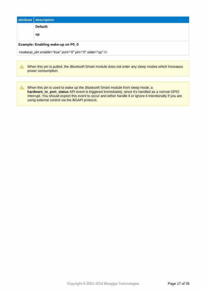
Default:
up
Example: Enabling wake-up on P0_0
<wakeup_pin enable="true" port="0" pin="0" state="up" />
When this pin is pulled, the Smart module does not enter any sleep modes which increasesBluetoothpower consumption.
When this pin is used to wake up the Smart module from sleep mode, a Bluetooth API event is triggered immediately, since it's handled as a normal GPIOhardware_io_port_status
interrupt. You should expect this event to occur and either handle it or ignore it intentionally if you areusing external control via the BGAPI protocol.
Copyright © 2001-2014 Bluegiga Technologies Page of 18 36
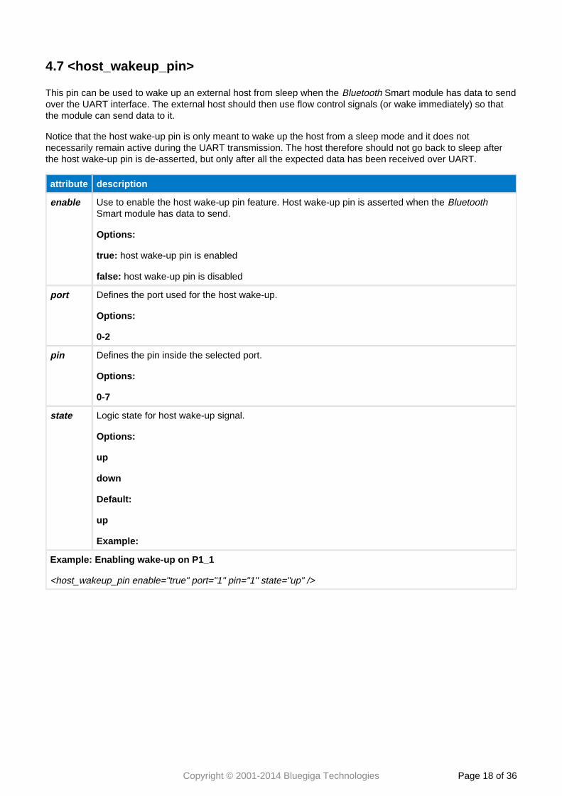
4.7 <host_wakeup_pin>
This pin can be used to wake up an external host from sleep when the Smart module has data to sendBluetoothover the UART interface. The external host should then use flow control signals (or wake immediately) so thatthe module can send data to it.
Notice that the host wake-up pin is only meant to wake up the host from a sleep mode and it does notnecessarily remain active during the UART transmission. The host therefore should not go back to sleep afterthe host wake-up pin is de-asserted, but only after all the expected data has been received over UART.
attribute description
enable Use to enable the host wake-up pin feature. Host wake-up pin is asserted when the BluetoothSmart module has data to send.
Options:
true: host wake-up pin is enabled
false: host wake-up pin is disabled
port Defines the port used for the host wake-up.
Options:
0-2
pin Defines the pin inside the selected port.
Options:
0-7
state Logic state for host wake-up signal.
Options:
up
down
Default:
up
Example:
Example: Enabling wake-up on P1_1
<host_wakeup_pin enable="true" port="1" pin="1" state="up" />
Copyright © 2001-2014 Bluegiga Technologies Page of 19 36
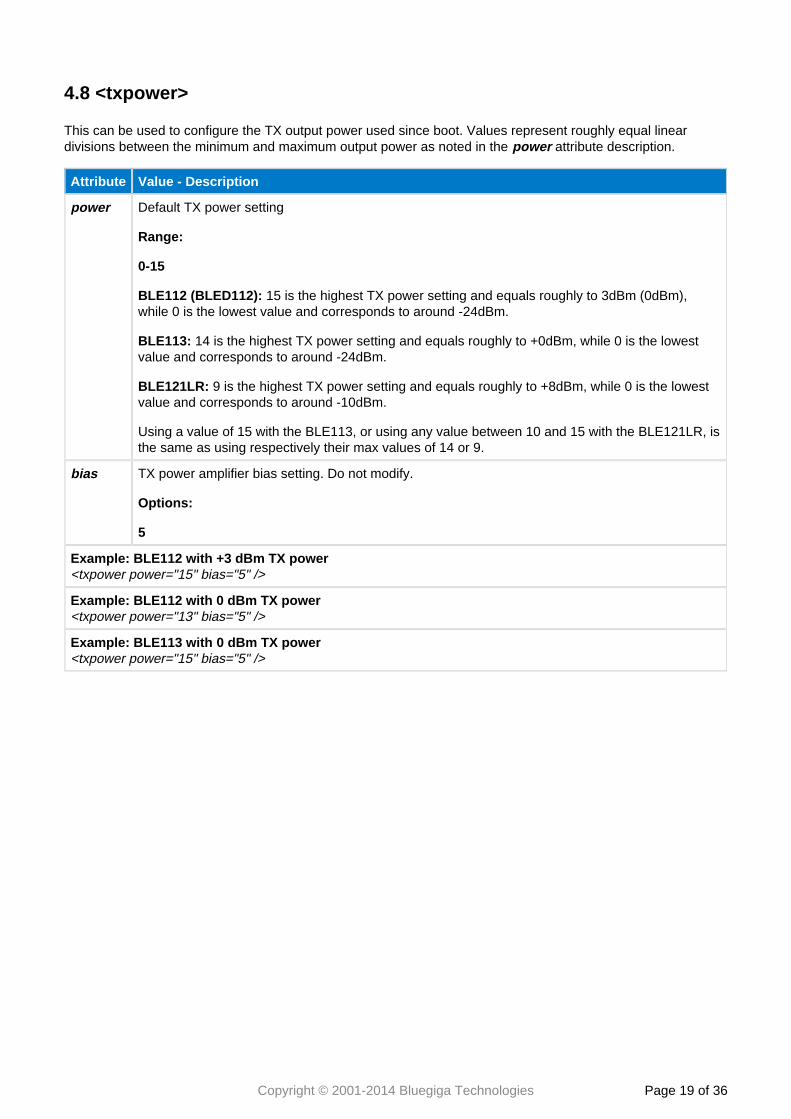
4.8 <txpower>
This can be used to configure the TX output power used since boot. Values represent roughly equal lineardivisions between the minimum and maximum output power as noted in the attribute description.power
Attribute Value - Description
power Default TX power setting
Range:
0-15
BLE112 (BLED112): 15 is the highest TX power setting and equals roughly to 3dBm (0dBm),while 0 is the lowest value and corresponds to around -24dBm.
BLE113: 14 is the highest TX power setting and equals roughly to +0dBm, while 0 is the lowestvalue and corresponds to around -24dBm.
BLE121LR: 9 is the highest TX power setting and equals roughly to +8dBm, while 0 is the lowestvalue and corresponds to around -10dBm.
Using a value of 15 with the BLE113, or using any value between 10 and 15 with the BLE121LR, isthe same as using respectively their max values of 14 or 9.
bias TX power amplifier bias setting. Do not modify.
Options:
5
Example: BLE112 with +3 dBm TX power<txpower power="15" bias="5" />
Example: BLE112 with 0 dBm TX power<txpower power="13" bias="5" />
Example: BLE113 with 0 dBm TX power<txpower power="15" bias="5" />
Copyright © 2001-2014 Bluegiga Technologies Page of 20 36
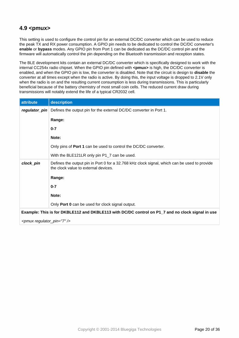
4.9 <pmux>
This setting is used to configure the control pin for an external DC/DC converter which can be used to reducethe peak TX and RX power consumption. A GPIO pin needs to be dedicated to control the DC/DC converter's
or modes. Any GPIO pin from Port 1 can be dedicated as the DC/DC control pin and theenable bypassfirmware will automatically control the pin depending on the Bluetooth transmission and reception states.
The BLE development kits contain an external DC/DC converter which is specifically designed to work with theinternal CC254x radio chipset. When the GPIO pin defined with is high, the DC/DC converter is<pmux>enabled, and when the GPIO pin is low, the converter is disabled. Note that the circuit is design to thedisable converter at all times except when the radio is active. By doing this, the input voltage is dropped to 2.1V onlywhen the radio is on and the resulting current consumption is less during transmissions. This is particularlybeneficial because of the battery chemistry of most small coin cells. The reduced current draw duringtransmissions will notably extend the life of a typical CR2032 cell.
attribute description
regulator_pin Defines the output pin for the external DC/DC converter in Port 1.
Range:
0-7
Note:
Only pins of can be used to control the DC/DC converter.Port 1
With the BLE121LR only pin P1_7 can be used.
clock_pin Defines the output pin in Port 0 for a 32.768 kHz clock signal, which can be used to providethe clock value to external devices.
Range:
0-7
Note:
Only can be used for clock signal output.Port 0
Example: This is for DKBLE112 and DKBLE113 with DC/DC control on P1_7 and no clock signal in use
<pmux regulator_pin="7" />
Copyright © 2001-2014 Bluegiga Technologies Page of 21 36
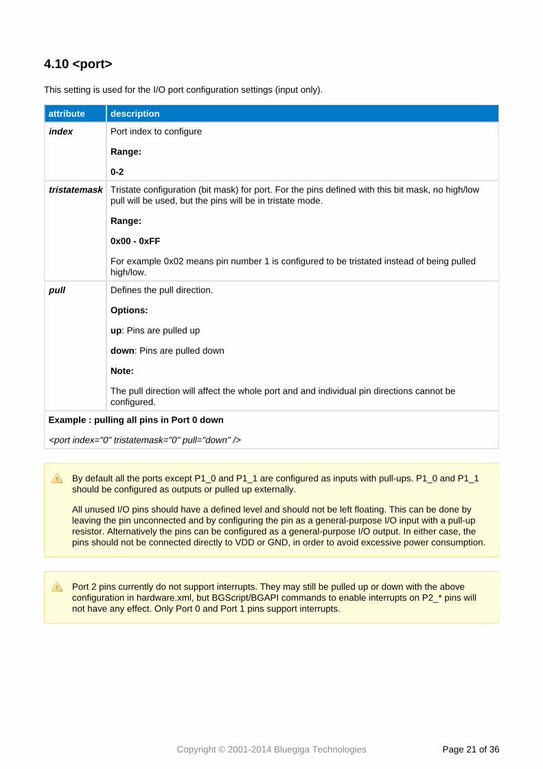
4.10 <port>
This setting is used for the I/O port configuration settings (input only).
attribute description
index Port index to configure
Range:
0-2
tristatemask Tristate configuration (bit mask) for port. For the pins defined with this bit mask, no high/lowpull will be used, but the pins will be in tristate mode.
Range:
0x00 - 0xFF
For example 0x02 means pin number 1 is configured to be tristated instead of being pulledhigh/low.
pull Defines the pull direction.
Options:
up: Pins are pulled up
down: Pins are pulled down
Note:
The pull direction will affect the whole port and and individual pin directions cannot beconfigured.
Example : pulling all pins in Port 0 down
<port index="0" tristatemask="0" pull="down" />
By default all the ports except P1_0 and P1_1 are configured as inputs with pull-ups. P1_0 and P1_1should be configured as outputs or pulled up externally.
All unused I/O pins should have a defined level and should not be left floating. This can be done byleaving the pin unconnected and by configuring the pin as a general-purpose I/O input with a pull-upresistor. Alternatively the pins can be configured as a general-purpose I/O output. In either case, thepins should not be connected directly to VDD or GND, in order to avoid excessive power consumption.
Port 2 pins currently do not support interrupts. They may still be pulled up or down with the aboveconfiguration in hardware.xml, but BGScript/BGAPI commands to enable interrupts on P2_* pins willnot have any effect. Only Port 0 and Port 1 pins support interrupts.
Copyright © 2001-2014 Bluegiga Technologies Page of 22 36
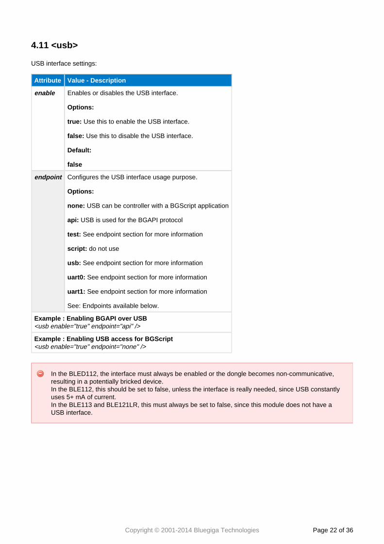
4.11 <usb>
USB interface settings:
Attribute Value - Description
enable Enables or disables the USB interface.
Options:
true: Use this to enable the USB interface.
false: Use this to disable the USB interface.
Default:
false
endpoint Configures the USB interface usage purpose.
Options:
none: USB can be controller with a BGScript application
api: USB is used for the BGAPI protocol
test: See endpoint section for more information
script: do not use
usb: See endpoint section for more information
uart0: See endpoint section for more information
uart1: See endpoint section for more information
See: Endpoints available below.
Example : Enabling BGAPI over USB<usb enable="true" endpoint="api" />
Example : Enabling USB access for BGScript<usb enable="true" endpoint="none" />
In the BLED112, the interface must always be enabled or the dongle becomes non-communicative,resulting in a potentially bricked device.In the BLE112, this should be set to false, unless the interface is really needed, since USB constantlyuses 5+ mA of current.In the BLE113 and BLE121LR, this must always be set to false, since this module does not have aUSB interface.
Copyright © 2001-2014 Bluegiga Technologies Page of 23 36
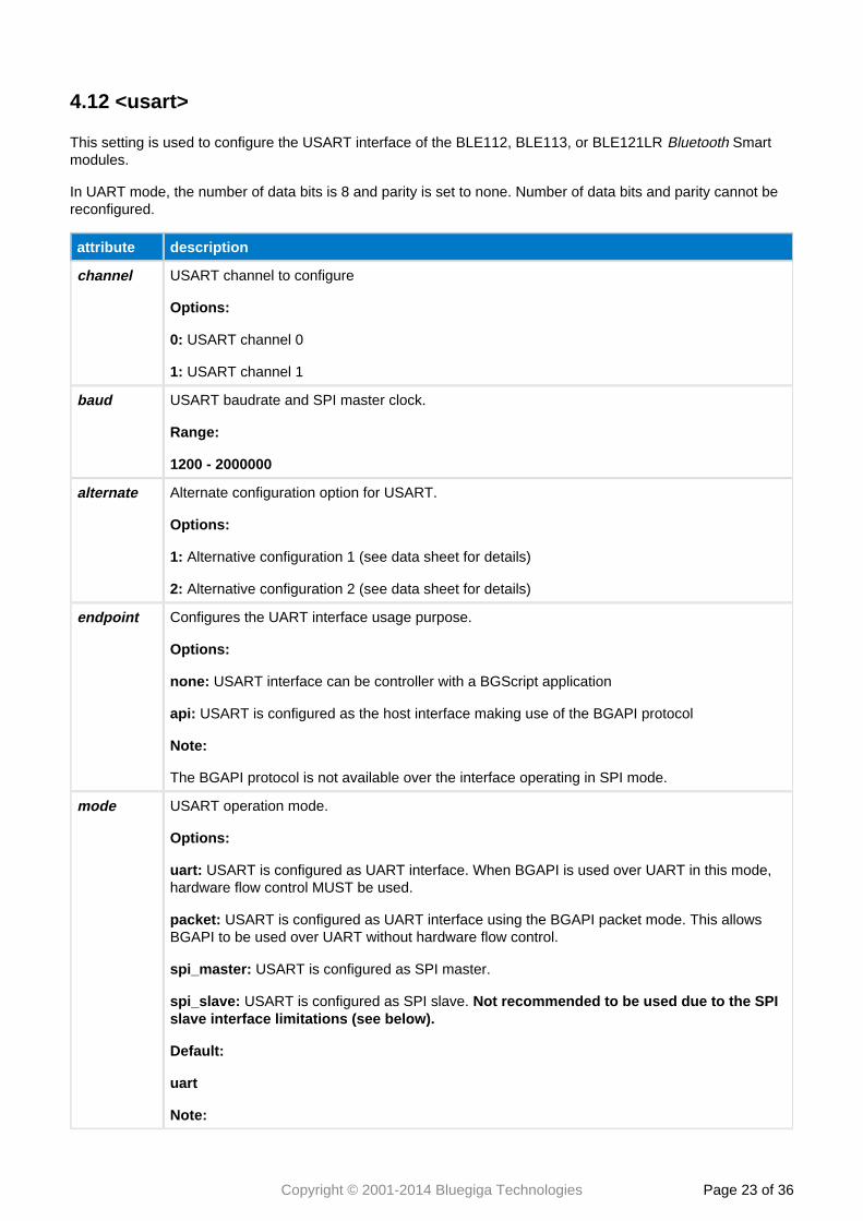
4.12 <usart>
This setting is used to configure the USART interface of the BLE112, BLE113, or BLE121LR SmartBluetoothmodules.
In UART mode, the number of data bits is 8 and parity is set to none. Number of data bits and parity cannot bereconfigured.
attribute description
channel USART channel to configure
Options:
0: USART channel 0
1: USART channel 1
baud USART baudrate and SPI master clock.
Range:
1200 - 2000000
alternate Alternate configuration option for USART.
Options:
1: Alternative configuration 1 (see data sheet for details)
2: Alternative configuration 2 (see data sheet for details)
endpoint Configures the UART interface usage purpose.
Options:
none: USART interface can be controller with a BGScript application
api: USART is configured as the host interface making use of the BGAPI protocol
Note:
The BGAPI protocol is not available over the interface operating in SPI mode.
mode USART operation mode.
Options:
uart: USART is configured as UART interface. When BGAPI is used over UART in this mode,hardware flow control MUST be used.
packet: USART is configured as UART interface using the BGAPI packet mode. This allowsBGAPI to be used over UART without hardware flow control.
spi_master: USART is configured as SPI master.
spi_slave: USART is configured as SPI slave. Not recommended to be used due to the SPIslave interface limitations (see below).
Default:
uart
Note:
Copyright © 2001-2014 Bluegiga Technologies Page of 24 36
attribute description
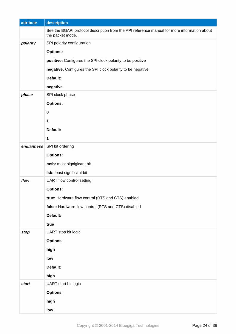
See the BGAPI protocol description from the API reference manual for more information aboutthe packet mode.
polarity SPI polarity configuration
Options:
positive: Configures the SPI clock polarity to be positive
negative: Configures the SPI clock polarity to be negative
Default:
negative
phase SPI clock phase
Options:
0
1
Default:
1
endianness SPI bit ordering
Options:
msb: most signigicant bit
lsb: least significant bit
flow UART flow control setting
Options:
true: Hardware flow control (RTS and CTS) enabled
false: Hardware flow control (RTS and CTS) disabled
Default:
true
stop UART stop bit logic
Options:
high
low
Default:
high
start UART start bit logic
Options:
high
low
Copyright © 2001-2014 Bluegiga Technologies Page of 25 36
attribute description
Default:
low
Note:Must be different than stop bit logic.
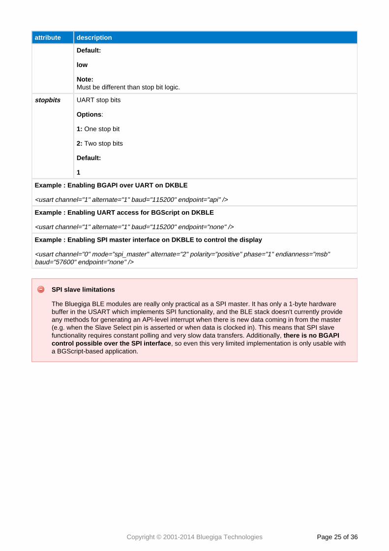
stopbits UART stop bits
Options:
1: One stop bit
2: Two stop bits
Default:
1
Example : Enabling BGAPI over UART on DKBLE
<usart channel="1" alternate="1" baud="115200" endpoint="api" />
Example : Enabling UART access for BGScript on DKBLE
<usart channel="1" alternate="1" baud="115200" endpoint="none" />
Example : Enabling SPI master interface on DKBLE to control the display
<usart channel="0" mode="spi_master" alternate="2" polarity="positive" phase="1" endianness="msb"baud="57600" endpoint="none" />
SPI slave limitations
The Bluegiga BLE modules are really only practical as a SPI master. It has only a 1-byte hardwarebuffer in the USART which implements SPI functionality, and the BLE stack doesn't currently provideany methods for generating an API-level interrupt when there is new data coming in from the master(e.g. when the Slave Select pin is asserted or when data is clocked in). This means that SPI slavefunctionality requires constant polling and very slow data transfers. Additionally, there is no BGAPI
, so even this very limited implementation is only usable withcontrol possible over the SPI interfacea BGScript-based application.
Copyright © 2001-2014 Bluegiga Technologies Page of 26 36
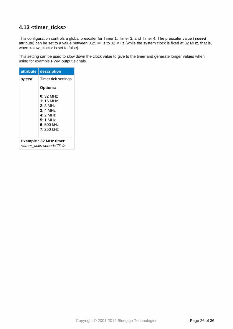
4.13 <timer_ticks>
This configuration controls a global prescaler for Timer 1, Timer 3, and Timer 4. The prescaler value (speedattribute) can be set to a value between 0.25 MHz to 32 MHz (while the system clock is fixed at 32 MHz, that is,when <slow_clock> is set to false).
This setting can be used to slow down the clock value to give to the timer and generate longer values whenusing for example PWM output signals.
attribute description
speed Timer tick settings.
Options:
0: 32 MHz: 16 MHz1: 8 MHz2: 4 MHz3: 2 MHz4: 1 MHz5: 500 kHz6: 250 kHz7
Example : 32 MHz timer<timer_ticks speed="0" />
Copyright © 2001-2014 Bluegiga Technologies Page of 27 36
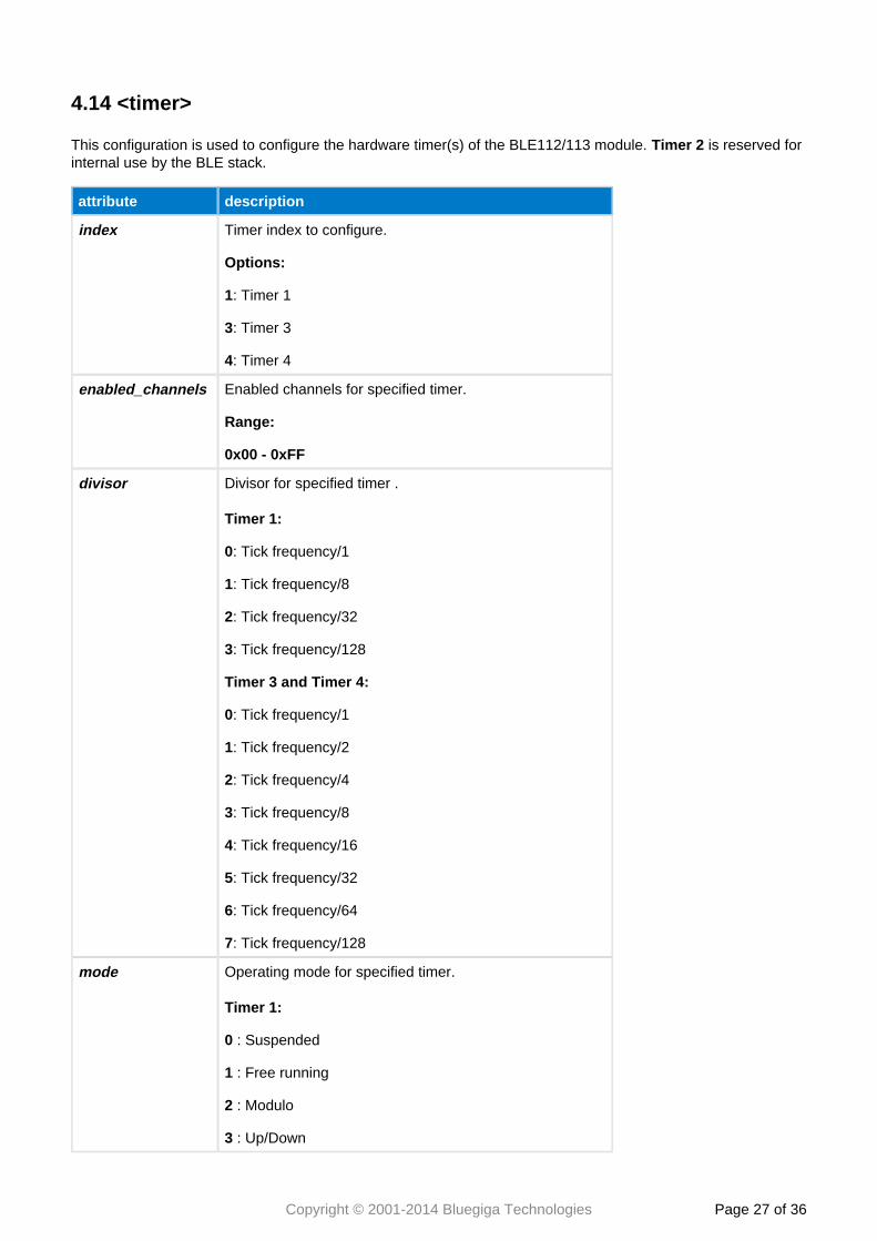
4.14 <timer>
This configuration is used to configure the hardware timer(s) of the BLE112/113 module. is reserved forTimer 2internal use by the BLE stack.
attribute description
index Timer index to configure.
Options:
1: Timer 1
3: Timer 3
4: Timer 4
enabled_channels Enabled channels for specified timer.
Range:
0x00 - 0xFF
divisor Divisor for specified timer .
Timer 1:
0: Tick frequency/1
1: Tick frequency/8
2: Tick frequency/32
3: Tick frequency/128
Timer 3 and Timer 4:
0: Tick frequency/1
1: Tick frequency/2
2: Tick frequency/4
3: Tick frequency/8
4: Tick frequency/16
5: Tick frequency/32
6: Tick frequency/64
7: Tick frequency/128
mode Operating mode for specified timer.
Timer 1:
0 : Suspended
1 : Free running
2 : Modulo
3 : Up/Down
Copyright © 2001-2014 Bluegiga Technologies Page of 28 36
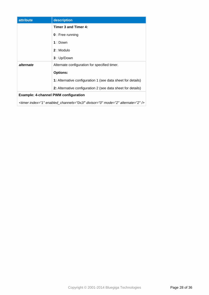
attribute description
Timer 3 and Timer 4:
0 : Free running
1 : Down
2 : Modulo
3 : Up/Down
alternate Alternate configuration for specified timer.
Options:
1: Alternative configuration 1 (see data sheet for details)
2: Alternative configuration 2 (see data sheet for details)
Example: 4-channel PWM configuration
<timer index="1" enabled_channels="0x1f" divisor="0" mode="2" alternate="2" />
Copyright © 2001-2014 Bluegiga Technologies Page of 29 36
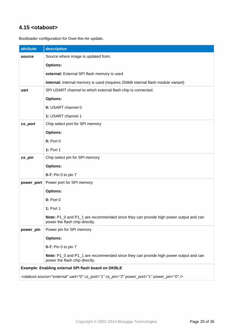
4.15 <otaboot>
Bootloader configuration for Over-the-Air update.
attribute description
source Source where image is updated from.
Options:
external: External SPI flash memory is used
internal: Internal memory is used (requires 256kB internal flash module variant)
uart SPI USART channel to which external flash chip is connected.
Options:
0: USART channel 0
1: USART channel 1
cs_port Chip select port for SPI memory
Options:
0: Port 0
1: Port 1
cs_pin Chip select pin for SPI memory
Options:
0-7: Pin 0 to pin 7
power_port Power port for SPI memory
Options:
0: Port 0
1: Port 1
Note: P1_0 and P1_1 are recommended since they can provide high power output and canpower the flash chip directly.
power_pin Power pin for SPI memory
Options:
0-7: Pin 0 to pin 7
Note: P1_0 and P1_1 are recommended since they can provide high power output and canpower the flash chip directly.
Example: Enabling external SPI flash board on DKBLE
<otaboot source="external" uart="0" cs_port="1" cs_pin="2" power_port="1" power_pin="0" />
Copyright © 2001-2014 Bluegiga Technologies Page of 30 36
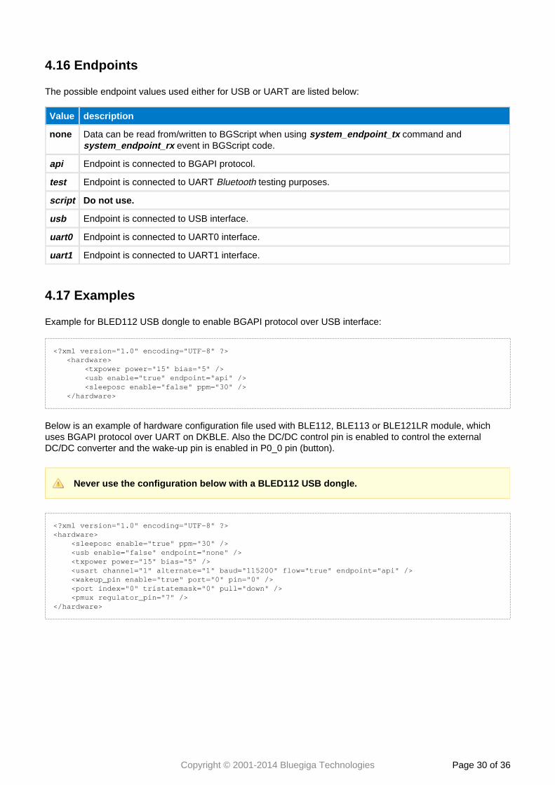
4.16 Endpoints
The possible endpoint values used either for USB or UART are listed below:
Value description
none Data can be read from/written to BGScript when using command and system_endpoint_tx event in BGScript code.system_endpoint_rx
api Endpoint is connected to BGAPI protocol.
test Endpoint is connected to UART testing purposes.Bluetooth
script Do not use.
usb Endpoint is connected to USB interface.
uart0 Endpoint is connected to UART0 interface.
uart1 Endpoint is connected to UART1 interface.
4.17 Examples
Example for BLED112 USB dongle to enable BGAPI protocol over USB interface:
<?xml version="1.0" encoding="UTF-8" ?> <hardware> <txpower power="15" bias="5" /> <usb enable="true" endpoint="api" /> <sleeposc enable="false" ppm="30" /> </hardware>
Below is an example of hardware configuration file used with BLE112, BLE113 or BLE121LR module, whichuses BGAPI protocol over UART on DKBLE. Also the DC/DC control pin is enabled to control the externalDC/DC converter and the wake-up pin is enabled in P0_0 pin (button).
Never use the configuration below with a BLED112 USB dongle.
<?xml version="1.0" encoding="UTF-8" ?><hardware> <sleeposc enable="true" ppm="30" /> <usb enable="false" endpoint="none" /> <txpower power="15" bias="5" /> <usart channel="1" alternate="1" baud="115200" flow="true" endpoint="api" /> <wakeup_pin enable="true" port="0" pin="0" /> <port index="0" tristatemask="0" pull="down" /> <pmux regulator_pin="7" /></hardware>
Copyright © 2001-2014 Bluegiga Technologies Page of 31 36
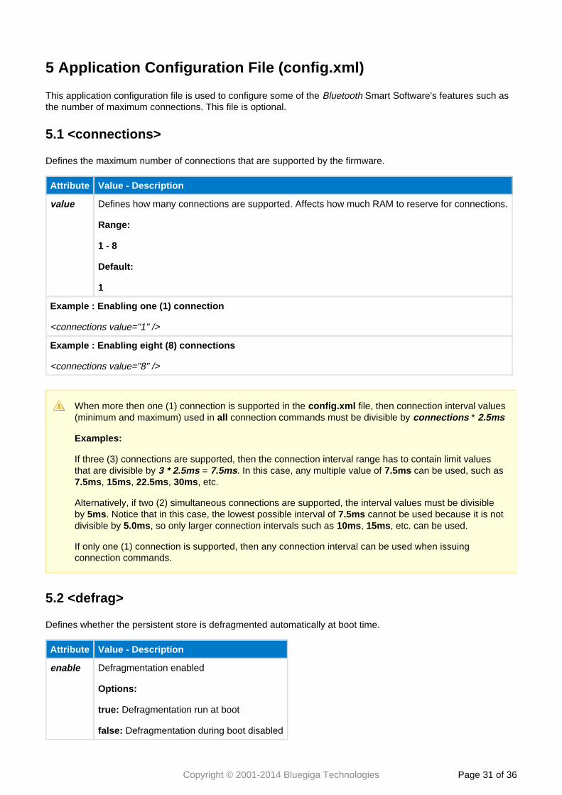
5 Application Configuration File (config.xml)
This application configuration file is used to configure some of the Smart Software's features such asBluetooththe number of maximum connections. This file is optional.
5.1 <connections>
Defines the maximum number of connections that are supported by the firmware.
Attribute Value - Description
value Defines how many connections are supported. Affects how much RAM to reserve for connections.
Range:
1 - 8
Default:
1
Example : Enabling one (1) connection
<connections value="1" />
Example : Enabling eight (8) connections
<connections value="8" />
When more then one (1) connection is supported in the file, then connection interval valuesconfig.xml(minimum and maximum) used in connection commands must be divisible by * all connections 2.5ms
Examples:
If three (3) connections are supported, then the connection interval range has to contain limit valuesthat are divisible by = . In this case, any multiple value of can be used, such as 3 * 2.5ms 7.5ms 7.5ms
, , , , etc.7.5ms 15ms 22.5ms 30ms
Alternatively, if two (2) simultaneous connections are supported, the interval values must be divisibleby . Notice that in this case, the lowest possible interval of cannot be used because it is not5ms 7.5msdivisible by , so only larger connection intervals such as , , etc. can be used.5.0ms 10ms 15ms
If only one (1) connection is supported, then any connection interval can be used when issuingconnection commands.
5.2 <defrag>
Defines whether the persistent store is defragmented automatically at boot time.
Attribute Value - Description
enable Defragmentation enabled
Options:
true: Defragmentation run at boot
false: Defragmentation during boot disabled
Copyright © 2001-2014 Bluegiga Technologies Page of 32 36
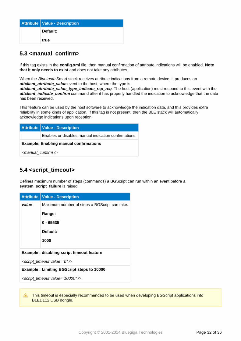
Attribute Value - Description
Default:
true
5.3 <manual_confirm>
If this tag exists in the file, then manual confirmation of attribute indications will be enabled. config.xml Note and does not take any attributes.that it only needs to exist
When the Smart stack receives attribute indications from a remote device, it produces an Bluetooth event to the host, where the type is attclient_attribute_value
. The host (application) must respond to this event with the attclient_attribute_value_type_indicate_rsp_req command after it has properly handled the indication to acknowledge that the dataattclient_indicate_confirm
has been received.
This feature can be used by the host software to acknowledge the indication data, and this provides extrareliability in some kinds of application. If this tag is not present, then the BLE stack will automaticallyacknowledge indications upon reception.
Attribute Value - Description
Enables or disables manual indication confirmations.
Example: Enabling manual confirmations
<manual_confirm />
5.4 <script_timeout>
Defines maximum number of steps (commands) a BGScript can run within an event before a is raised.system_script_failure
Attribute Value - Description
value Maximum number of steps a BGScript can take.
Range:
0 - 65535
Default:
1000
Example : disabling script timeout feature
<script_timeout value="0" />
Example : Limiting BGScript steps to 10000
<script_timeout value="10000" />
This timeout is especially recommended to be used when developing BGScript applications intoBLED112 USB dongle.
Copyright © 2001-2014 Bluegiga Technologies Page of 33 36
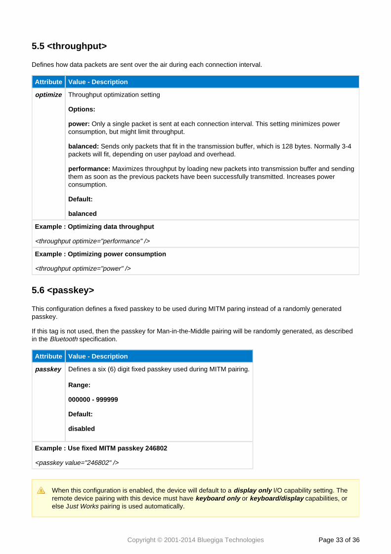
5.5 <throughput>
Defines how data packets are sent over the air during each connection interval.
Attribute Value - Description
optimize Throughput optimization setting
Options:
power: Only a single packet is sent at each connection interval. This setting minimizes powerconsumption, but might limit throughput.
balanced: Sends only packets that fit in the transmission buffer, which is 128 bytes. Normally 3-4packets will fit, depending on user payload and overhead.
performance: Maximizes throughput by loading new packets into transmission buffer and sendingthem as soon as the previous packets have been successfully transmitted. Increases powerconsumption.
Default:
balanced
Example : Optimizing data throughput
<throughput optimize="performance" />
Example : Optimizing power consumption
<throughput optimize="power" />
5.6 <passkey>
This configuration defines a fixed passkey to be used during MITM paring instead of a randomly generatedpasskey.
If this tag is not used, then the passkey for Man-in-the-Middle pairing will be randomly generated, as describedin the specification.Bluetooth
Attribute Value - Description
passkey Defines a six (6) digit fixed passkey used during MITM pairing.
Range:
000000 - 999999
Default:
disabled
Example : Use fixed MITM passkey 246802
<passkey value="246802" />
When this configuration is enabled, the device will default to a I/O capability setting. Thedisplay onlyremote device pairing with this device must have or capabilities, orkeyboard only keyboard/displayelse J pairing is used automatically.ust Works
Copyright © 2001-2014 Bluegiga Technologies Page of 34 36
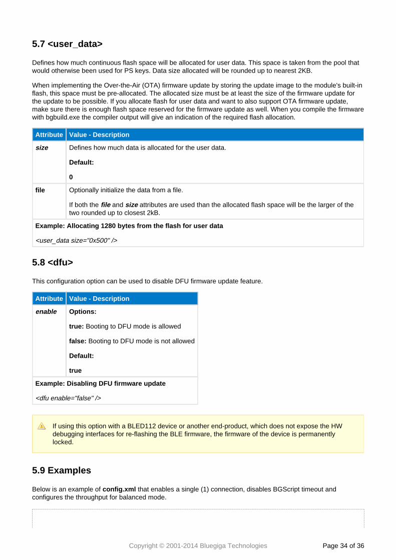
5.7 <user_data>
Defines how much continuous flash space will be allocated for user data. This space is taken from the pool thatwould otherwise been used for PS keys. Data size allocated will be rounded up to nearest 2KB.
When implementing the Over-the-Air (OTA) firmware update by storing the update image to the module's built-inflash, this space must be pre-allocated. The allocated size must be at least the size of the firmware update forthe update to be possible. If you allocate flash for user data and want to also support OTA firmware update,make sure there is enough flash space reserved for the firmware update as well. When you compile the firmwarewith bgbuild.exe the compiler output will give an indication of the required flash allocation.
Attribute Value - Description
size Defines how much data is allocated for the user data.
Default:
0
file Optionally initialize the data from a file.
If both the and attributes are used than the allocated flash space will be the larger of thefile sizetwo rounded up to closest 2kB.
Example: Allocating 1280 bytes from the flash for user data
<user_data size="0x500" />
5.8 <dfu>
This configuration option can be used to disable DFU firmware update feature.
Attribute Value - Description
enable Options:
true: Booting to DFU mode is allowed
false: Booting to DFU mode is not allowed
Default:
true
Example: Disabling DFU firmware update
<dfu enable="false" />
If using this option with a BLED112 device or another end-product, which does not expose the HWdebugging interfaces for re-flashing the BLE firmware, the firmware of the device is permanentlylocked.
5.9 Examples
Below is an example of that enables a single (1) connection, disables BGScript timeout andconfig.xmlconfigures the throughput for balanced mode.

Copyright © 2001-2014 Bluegiga Technologies Page of 35 36
<?xml version="1.0" encoding="UTF-8" ?><config> <connections value="1" /> <script_timeout value="0" /> <throughput optimize="balanced" /></config>
Copyright © 2001-2014 Bluegiga Technologies Page of 36 36
Contact information
Sales: [email protected]
Technical support: http://www.bluegiga.com/support/
Orders: [email protected]
WWW: http://www.bluegiga.com
Head Office / Finland: Phone: +358-9-4355 060
Fax: +358-9-4355 0660
Sinikalliontie 5 A
02630 ESPOO
FINLAND
Head address / Finland: P.O. Box 120
02631 ESPOO
FINLAND
Sales Office / USA: Phone: +1 770 291 2181
Fax: +1 770 291 2183
Bluegiga Technologies, Inc.
3235 Satellite Boulevard, Building 400, Suite 300
Duluth, GA, 30096, USA
Sales Office / Hong-Kong: Phone: +852 3182 7321
Fax: +852 3972 5777
Bluegiga Technologies, Inc.
Unit 10-18, 32/F, Tower 1, Millennium City 1,
388 Kwun Tong Road, Kwun Tong, Kowloon,
Hong Kong


