Page 1
[email protected] • ENGR-22_Lec-19_GDT-1.ppt1
Bruce Mayer, PE Engineering 22 – Engineering Design Graphics
Bruce Mayer, PELicensed Electrical & Mechanical Engineer
[email protected]
Engineering 22
GeometricGeometricDimensioninDimensionin
gg& &
TolerancingTolerancing
Page 2
[email protected] • ENGR-22_Lec-19_GDT-1.ppt2
Bruce Mayer, PE Engineering 22 – Engineering Design Graphics
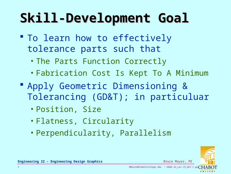
Skill-Development GoalSkill-Development Goal
To learn how to effectively tolerance parts such that • The Parts Function Correctly
• Fabrication Cost Is Kept To A Minimum
Apply Geometric Dimensioning & Tolerancing (GD&T); in particuluar• Position, Size
• Flatness, Circularity
• Perpendicularity, Parallelism
Page 3
[email protected] • ENGR-22_Lec-19_GDT-1.ppt3
Bruce Mayer, PE Engineering 22 – Engineering Design Graphics
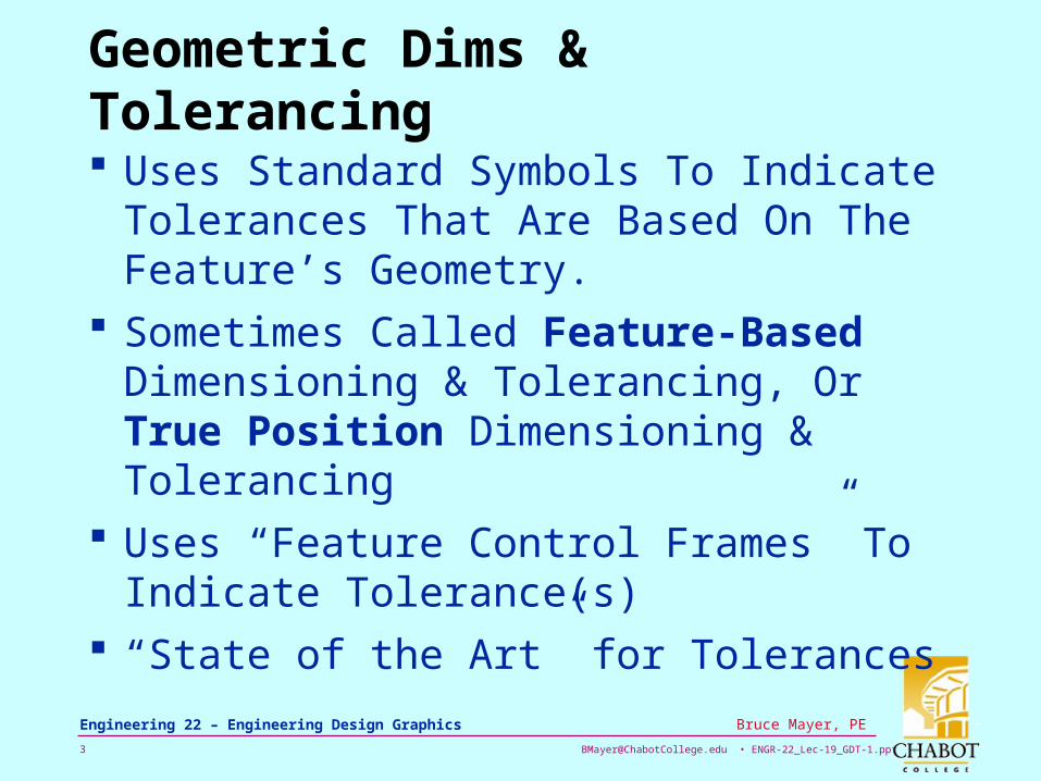
Geometric Dims & Tolerancing
Uses Standard Symbols To Indicate Tolerances That Are Based On The Feature’s Geometry.
Sometimes Called Feature-Based Dimensioning & Tolerancing, Or True Position Dimensioning & Tolerancing
Uses “Feature Control Frames” To Indicate Tolerance(s)
“State of the Art” for Tolerances
Page 4
[email protected] • ENGR-22_Lec-19_GDT-1.ppt4
Bruce Mayer, PE Engineering 22 – Engineering Design Graphics
Geometric?Geometric?
The “G” in GD&T refers to Geometric Forms • e.g., plane, circle, cylinder, sq, or hexagon
Theoretically these forms are Perfect – but any REAL Form will be Imperfect
In GD&T The Limits of Real Variation (tolerance) are Specified by the Diameter/Width of a Planer, Cylindrical, Annular, or Spherical Zone
Page 5
[email protected] • ENGR-22_Lec-19_GDT-1.ppt5
Bruce Mayer, PE Engineering 22 – Engineering Design Graphics
History of TolerancingHistory of Tolerancing
In the 1800’s, manufacturing used the “cut & try, file & fit” approach.
The plus-minus (or coordinate) system of tolerancing was next developed.
In the 1900’s, the first GD&T standards came out to improve the quality & utility of engineering drawings.
In 1966, the united GD&T standard was published → ANSI - Y14.5M
Page 6
[email protected] • ENGR-22_Lec-19_GDT-1.ppt6
Bruce Mayer, PE Engineering 22 – Engineering Design Graphics
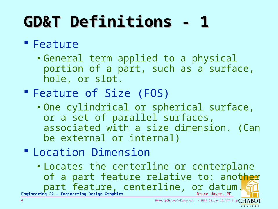
GD&T Definitions - 1GD&T Definitions - 1 Feature
• General term applied to a physical portion of a part, such as a surface, hole, or slot.
Feature of Size (FOS)• One cylindrical or spherical surface, or a set
of parallel surfaces, associated with a size dimension. (Can be external or internal)
Location Dimension• Locates the centerline or centerplane of a
part feature relative to: another part feature, centerline, or datum.
Page 7
[email protected] • ENGR-22_Lec-19_GDT-1.ppt7
Bruce Mayer, PE Engineering 22 – Engineering Design Graphics
GD&T Definitions - 2GD&T Definitions - 2
Tolerance Zones• all geometric tolerances have imaginary
tolerance zones that are the basis for acceptance or rejection of the product
• have specific shapes depending on the geometric tolerance and feature being controlled
Actual Local Size• the value of any individual distance at any
cross section of a FOS
Page 8
[email protected] • ENGR-22_Lec-19_GDT-1.ppt8
Bruce Mayer, PE Engineering 22 – Engineering Design Graphics
GD&T Definitions - 3GD&T Definitions - 3
Actual Mating Envelope (AME)• a similar perfect feature counterpart that
can be circumscribed/inscribed about/within the feature so it just contacts the surfaces at the highest & lowest points
• It is derived from an actual part
• Used When Calculating a “Bonus Tolerance”– More on this Next Time
Page 9
[email protected] • ENGR-22_Lec-19_GDT-1.ppt9
Bruce Mayer, PE Engineering 22 – Engineering Design Graphics
Envelope PrincipleEnvelope Principle
Proper Tolerancing establishes the ENVELOPE of the “perfect” part
Any deviation in FORM is acceptable, as long as it remains within the limits of size
Page 10
[email protected] • ENGR-22_Lec-19_GDT-1.ppt10
Bruce Mayer, PE Engineering 22 – Engineering Design Graphics
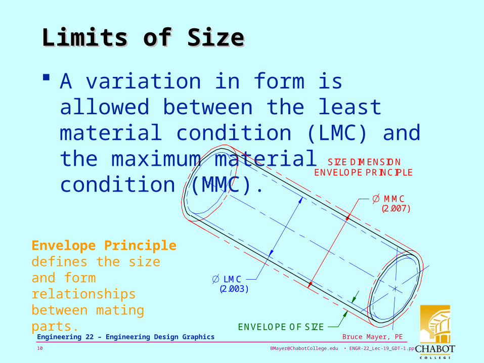
Limits of SizeLimits of Size
A variation in form is allowed between the least material condition (LMC) and the maximum material condition (MMC).
SIZE DIMENSION
MMC
LMC
ENVELOPE OF SIZE
(2.003)
(2.007)
ENVELOPE PRINCIPLE
Envelope Principle defines the size and form relationships between mating parts.
Page 11
[email protected] • ENGR-22_Lec-19_GDT-1.ppt11
Bruce Mayer, PE Engineering 22 – Engineering Design Graphics
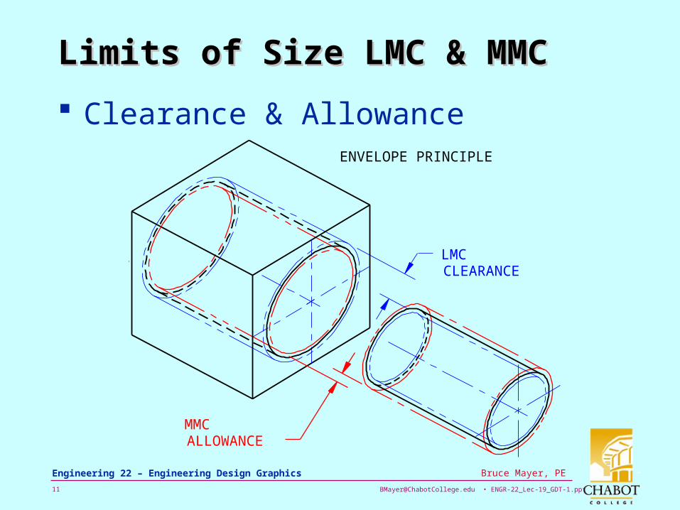
Limits of Size LMC & MMCLimits of Size LMC & MMC
Clearance & AllowanceENVELOPE PRINCIPLE
LMCCLEARANCE
MMCALLOWANCE
Page 12
[email protected] • ENGR-22_Lec-19_GDT-1.ppt12
Bruce Mayer, PE Engineering 22 – Engineering Design Graphics
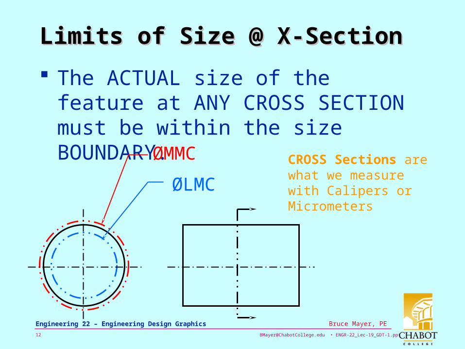
Limits of Size @ X-SectionLimits of Size @ X-Section
The ACTUAL size of the feature at ANY CROSS SECTION must be within the size BOUNDARY.
ØMMC
ØLMC
CROSS Sections are what we measure with Calipers or Micrometers
Page 13
[email protected] • ENGR-22_Lec-19_GDT-1.ppt13
Bruce Mayer, PE Engineering 22 – Engineering Design Graphics
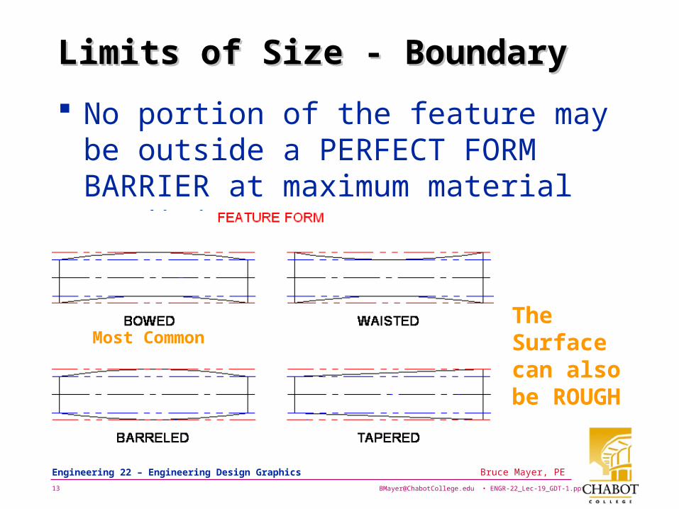
Limits of Size - BoundaryLimits of Size - Boundary
No portion of the feature may be outside a PERFECT FORM BARRIER at maximum material condition (MMC).
Most CommonThe Surface can also be ROUGH
Page 14
[email protected] • ENGR-22_Lec-19_GDT-1.ppt14
Bruce Mayer, PE Engineering 22 – Engineering Design Graphics
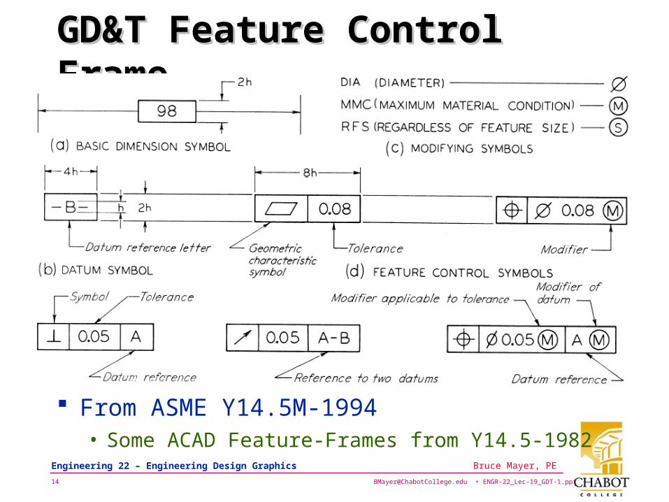
GD&T Feature Control FrameGD&T Feature Control Frame
From ASME Y14.5M-1994• Some ACAD Feature-Frames from Y14.5-1982
Page 15
[email protected] • ENGR-22_Lec-19_GDT-1.ppt15
Bruce Mayer, PE Engineering 22 – Engineering Design Graphics
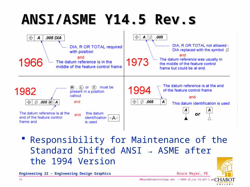
ANSI/ASME Y14.5 Rev.sANSI/ASME Y14.5 Rev.s
Responsibility for Maintenance of the Standard Shifted ANSI → ASME after the 1994 Version
Page 16
[email protected] • ENGR-22_Lec-19_GDT-1.ppt16
Bruce Mayer, PE Engineering 22 – Engineering Design Graphics
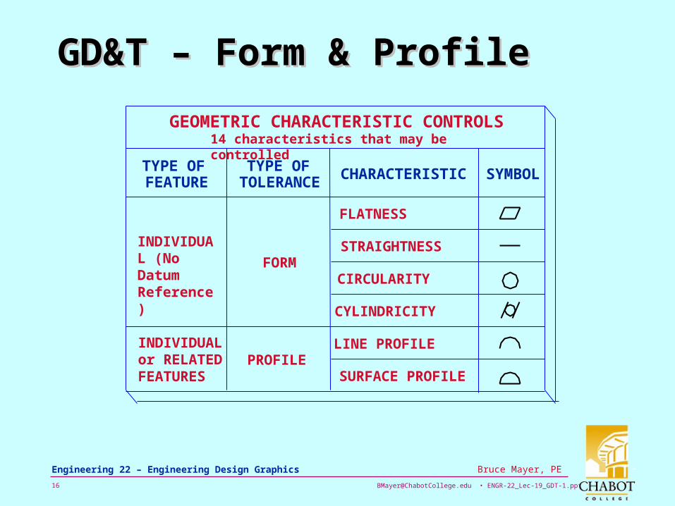
GD&T – Form & ProfileGD&T – Form & Profile
INDIVIDUAL (No Datum Reference)
INDIVIDUAL or RELATED FEATURES
GEOMETRIC CHARACTERISTIC CONTROLS
TYPE OFFEATURE
TYPE OFTOLERANCE CHARACTERISTIC SYMBOL
FLATNESS
STRAIGHTNESS
CIRCULARITY
CYLINDRICITY
LINE PROFILE
SURFACE PROFILE
FORM
PROFILE
14 characteristics that may be controlled
Page 17
[email protected] • ENGR-22_Lec-19_GDT-1.ppt17
Bruce Mayer, PE Engineering 22 – Engineering Design Graphics
GD&T – Orient, RunOut, LoctnGD&T – Orient, RunOut, Loctn
RELATED FEATURES (Datum Reference Required)
GEOMETRIC CHARACTERISTIC CONTROLS
TYPE OFFEATURE
TYPE OFTOLERANCE CHARACTERISTIC SYMBOL
SYMMETRY
PERPENDICULARITY
ANGULARITY
PARALLELISM
CIRCULAR RUNOUT
TOTAL RUNOUT
CONCENTRICITY
POSITION
ORIENTATION
RUNOUT
LOCATION
14 characteristics that may be controlled
Page 18
[email protected] • ENGR-22_Lec-19_GDT-1.ppt18
Bruce Mayer, PE Engineering 22 – Engineering Design Graphics
Understanding Tolerance Zones Traditional ± type of tolerancing describes a
SQUARE zone for acceptable locations. GD&T describes a CIRCULAR zone around
the theoretically exact location for the feature.
Page 19
[email protected] • ENGR-22_Lec-19_GDT-1.ppt19
Bruce Mayer, PE Engineering 22 – Engineering Design Graphics
Basic Dimension A theoretically exact
dimension used to locate features in GD&T• The Dimension From
Which the Limits of Variation are Derived
Basic dimensions are UNtoleranced• These NOMINAL Dims
are THEORETICALLY Exact
Basic Dims Identified by Enclosure in a FRAME
Page 20
[email protected] • ENGR-22_Lec-19_GDT-1.ppt20
Bruce Mayer, PE Engineering 22 – Engineering Design Graphics
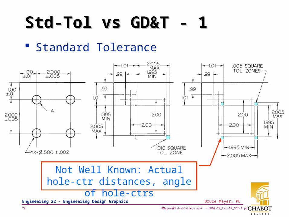
Std-Tol vs GD&T - 1Std-Tol vs GD&T - 1 Standard Tolerance
Not Well Known: Actual hole-ctr distances, angle of hole-ctrs
Page 21
[email protected] • ENGR-22_Lec-19_GDT-1.ppt21
Bruce Mayer, PE Engineering 22 – Engineering Design Graphics
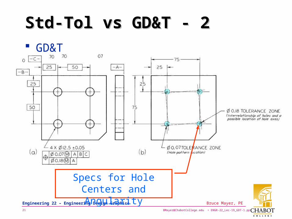
Std-Tol vs GD&T - 2Std-Tol vs GD&T - 2 GD&T
Specs for Hole Centers and Angularity
Page 22
[email protected] • ENGR-22_Lec-19_GDT-1.ppt22
Bruce Mayer, PE Engineering 22 – Engineering Design Graphics
Cylindrical Tolerance Zone
Line Connecting the Centers of the Circles at the Top & Bottom Surfaces Must Fall Completely Within The Tolerance Cylinder
Page 23
[email protected] • ENGR-22_Lec-19_GDT-1.ppt23
Bruce Mayer, PE Engineering 22 – Engineering Design Graphics
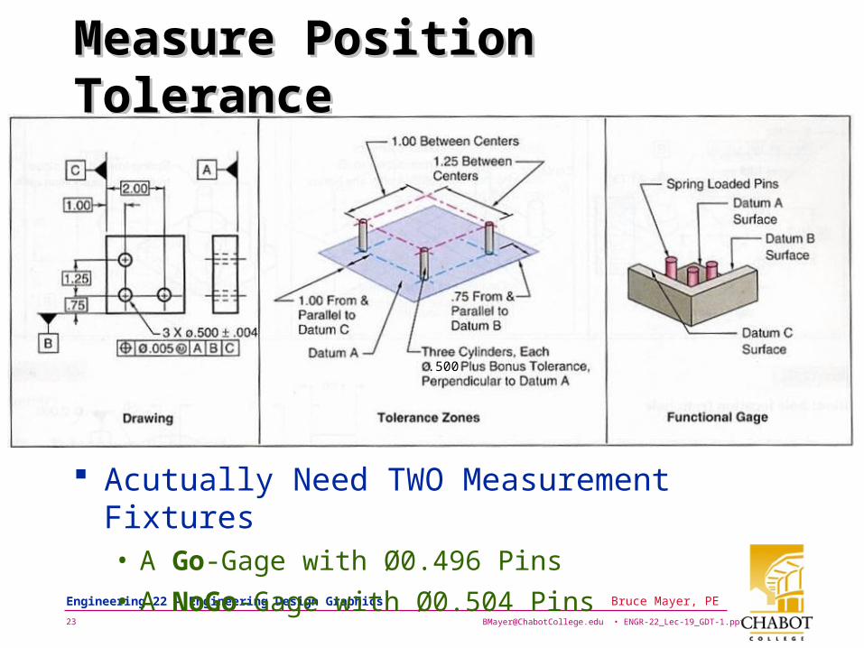
Measure Position ToleranceMeasure Position Tolerance
.500
Acutually Need TWO Measurement Fixtures• A Go-Gage with Ø0.496 Pins
• A NoGo-Gage with Ø0.504 Pins
Page 24
[email protected] • ENGR-22_Lec-19_GDT-1.ppt24
Bruce Mayer, PE Engineering 22 – Engineering Design Graphics
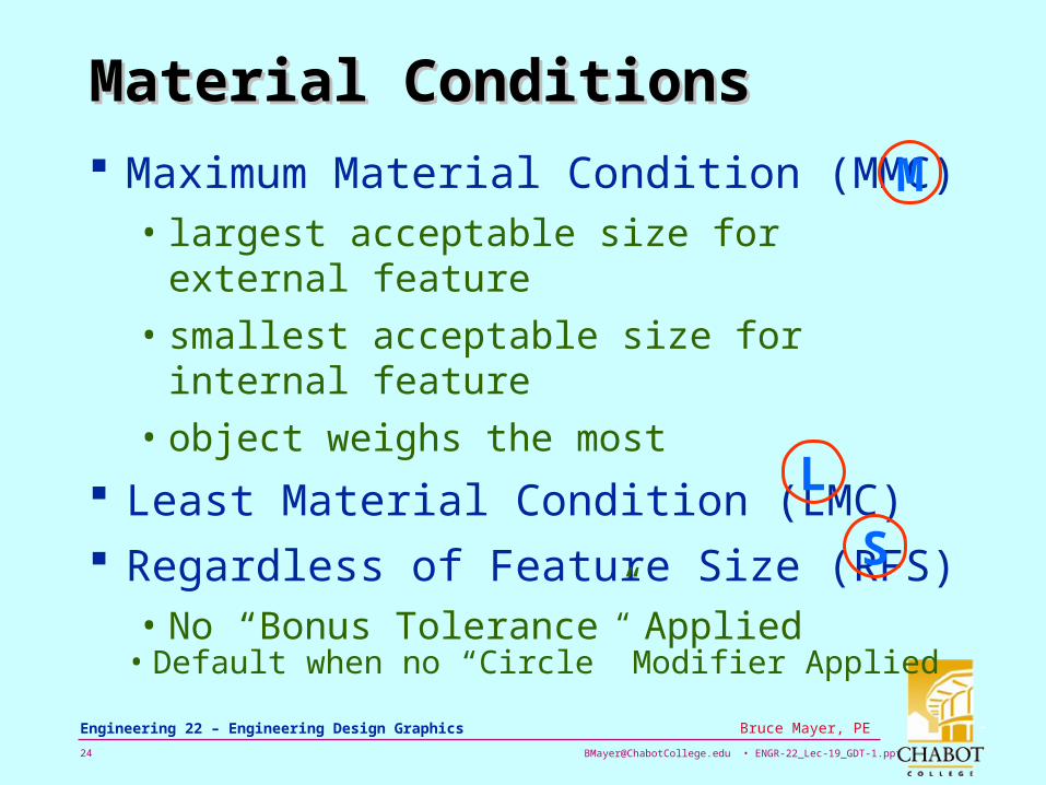
Material ConditionsMaterial Conditions
Maximum Material Condition (MMC)• largest acceptable size for external feature
• smallest acceptable size for internal feature
• object weighs the most
Least Material Condition (LMC) Regardless of Feature Size (RFS)
• No “Bonus Tolerance” Applied
M
L
S
• Default when no “Circle” Modifier Applied
Page 25
[email protected] • ENGR-22_Lec-19_GDT-1.ppt25
Bruce Mayer, PE Engineering 22 – Engineering Design Graphics
Maximum Material ConditionMaximum Material Condition
Same Gage Pins for LMC Holes w/ Wide-Spacing allow Larger Pos Tol.
Holes at MMC Holes at LMC
Smallest Holes at narrow Position accept 0.493” Gage Pins
Given
Page 26
[email protected] • ENGR-22_Lec-19_GDT-1.ppt26
Bruce Mayer, PE Engineering 22 – Engineering Design Graphics
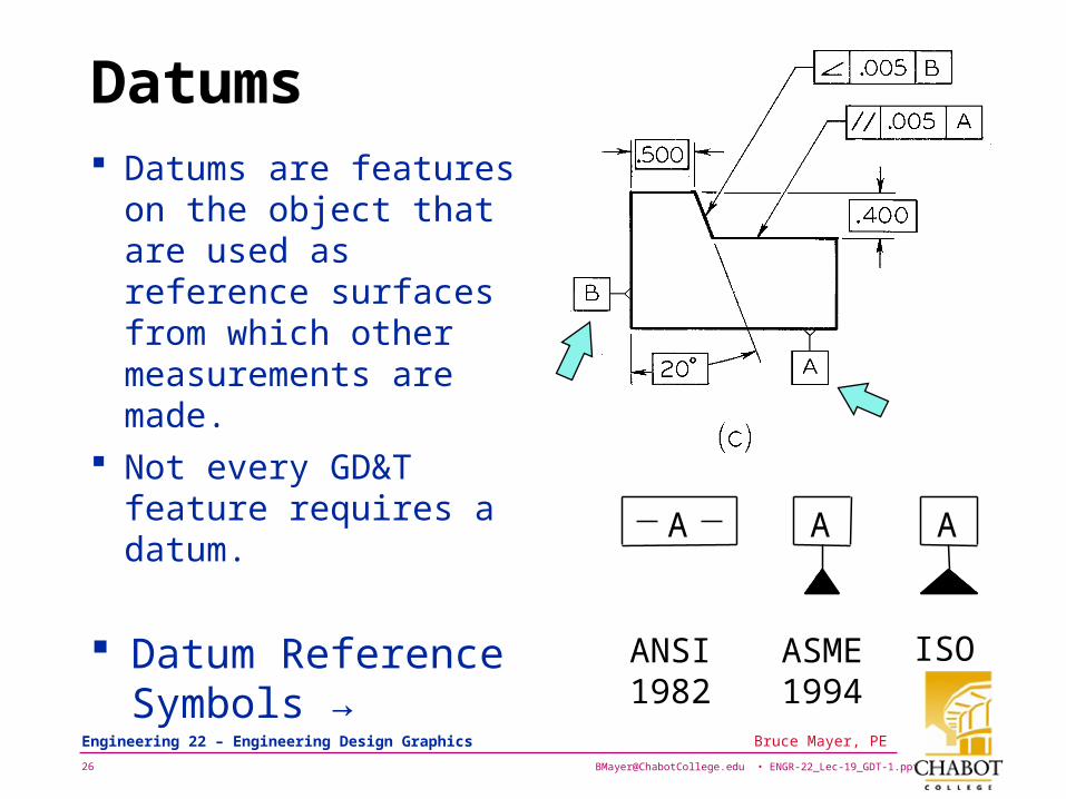
Datums Datums are features
on the object that are used as reference surfaces from which other measurements are made.
Not every GD&T feature requires a datum.
A
ISO
A
ANSI1982
ASME1994
A
Datum Reference Symbols →
Page 27
[email protected] • ENGR-22_Lec-19_GDT-1.ppt27
Bruce Mayer, PE Engineering 22 – Engineering Design Graphics
ANSI Datum FrameANSI Datum Frame
Still Widely Used• By ACAD for Example...
Page 28
[email protected] • ENGR-22_Lec-19_GDT-1.ppt28
Bruce Mayer, PE Engineering 22 – Engineering Design Graphics
Datums IllustratedDatums Illustrated
A
B
CC
AB
Page 29
[email protected] • ENGR-22_Lec-19_GDT-1.ppt29
Bruce Mayer, PE Engineering 22 – Engineering Design Graphics
FlatnessFlatness
Page 30
[email protected] • ENGR-22_Lec-19_GDT-1.ppt30
Bruce Mayer, PE Engineering 22 – Engineering Design Graphics
StraightnessStraightness
Page 31
[email protected] • ENGR-22_Lec-19_GDT-1.ppt31
Bruce Mayer, PE Engineering 22 – Engineering Design Graphics
Circularity (Roundness)Circularity (Roundness)
Page 32
[email protected] • ENGR-22_Lec-19_GDT-1.ppt32
Bruce Mayer, PE Engineering 22 – Engineering Design Graphics
CylindricityCylindricity
Page 33
[email protected] • ENGR-22_Lec-19_GDT-1.ppt33
Bruce Mayer, PE Engineering 22 – Engineering Design Graphics
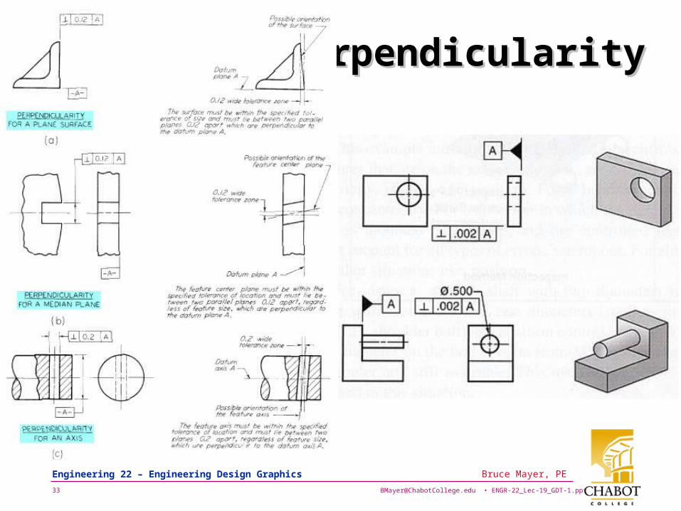
PerpendicularityPerpendicularity
Page 34
[email protected] • ENGR-22_Lec-19_GDT-1.ppt34
Bruce Mayer, PE Engineering 22 – Engineering Design Graphics
ParallelismParallelism
Page 35
[email protected] • ENGR-22_Lec-19_GDT-1.ppt35
Bruce Mayer, PE Engineering 22 – Engineering Design Graphics
Angular Tolerances Traditional
methods for tolerancing angles require that angled surfaces be veryaccurate near the vertex of the angle, but can vary more along the length of the angled feature.• That is, the allowable DISPLACEMENT in inches or mm
INCREASES with DISTANCE from the VERTEX
Page 36
[email protected] • ENGR-22_Lec-19_GDT-1.ppt36
Bruce Mayer, PE Engineering 22 – Engineering Design Graphics
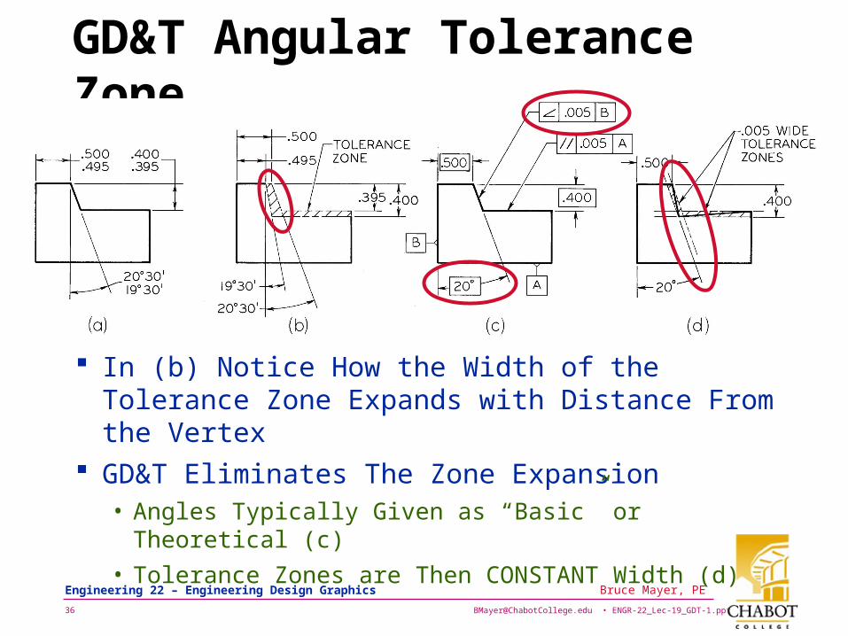
GD&T Angular Tolerance Zone
In (b) Notice How the Width of the Tolerance Zone Expands with Distance From the Vertex
GD&T Eliminates The Zone Expansion• Angles Typically Given as “Basic” or Theoretical (c)
• Tolerance Zones are Then CONSTANT Width (d)
Page 37
[email protected] • ENGR-22_Lec-19_GDT-1.ppt37
Bruce Mayer, PE Engineering 22 – Engineering Design Graphics
ProfileProfile
Page 38
[email protected] • ENGR-22_Lec-19_GDT-1.ppt38
Bruce Mayer, PE Engineering 22 – Engineering Design Graphics
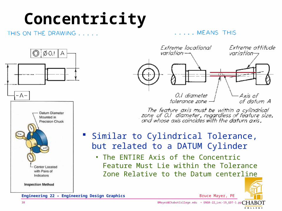
Concentricity
Similar to Cylindrical Tolerance, but related to a DATUM Cylinder • The ENTIRE Axis of the Concentric Feature
Must Lie within the Tolerance Zone Relative to the Datum centerline
Page 39
[email protected] • ENGR-22_Lec-19_GDT-1.ppt39
Bruce Mayer, PE Engineering 22 – Engineering Design Graphics
RunOutRunOut Note that the
CAUSE of the RunOut is NOT Known• In CIRCULAR
Case Could be some Combo of Circularity & Concentricity
• In TOTAL Case add Straightness to the list
Circular
Total
Page 40
[email protected] • ENGR-22_Lec-19_GDT-1.ppt40
Bruce Mayer, PE Engineering 22 – Engineering Design Graphics
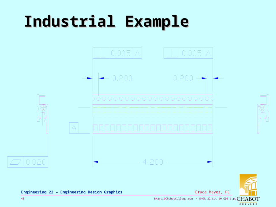
Industrial ExampleIndustrial Example
Page 41
[email protected] • ENGR-22_Lec-19_GDT-1.ppt41
Bruce Mayer, PE Engineering 22 – Engineering Design Graphics
GD&T Caveat → Use with CareGD&T Caveat → Use with Care
GDT is VERY Powerful, BUT…It it can be Quite CONFUSING and ESOTERIC
Many Degreed Engineers, as well as Most Drafters/Designers, and Some Machinists have only a Vague Notion About Meaning of GDT Symbols• MisApplication and Confusion-Induced
Delays are COMMON– e.g. Try asking what MMC or RFS means…
Page 42
[email protected] • ENGR-22_Lec-19_GDT-1.ppt42
Bruce Mayer, PE Engineering 22 – Engineering Design Graphics
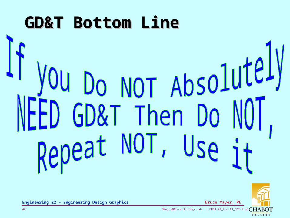
GD&T Bottom LineGD&T Bottom Line
Page 43
[email protected] • ENGR-22_Lec-19_GDT-1.ppt43
Bruce Mayer, PE Engineering 22 – Engineering Design Graphics
All Done for TodayAll Done for Today
GD&Tis Not forEveryone
Page 44
[email protected] • ENGR-22_Lec-19_GDT-1.ppt44
Bruce Mayer, PE Engineering 22 – Engineering Design Graphics
Bruce Mayer, PELicensed Electrical & Mechanical Engineer
[email protected]
Engr/Math/Physics 25
AppendiAppendixx
6972 23 xxxxf
Page 45
[email protected] • ENGR-22_Lec-19_GDT-1.ppt45
Bruce Mayer, PE Engineering 22 – Engineering Design Graphics
GD&T – Datum Surfaces and FeaturesGD&T – Datum Surfaces and Features