49
BME Senior Design Projects Fall 2012/Spring 2013 Sens or Circuit DAQ

BME Senior Design Projects Fall 2012/Spring 2013
SensorSensor
Circuit
DAQ

Table of Contents BME Senior Design Project at UCONN
Team 1 Off-road Wheelchair for Melody, Workstation and Pool Lift for Paige, Specialized Seat and Activity Tray for Sean
Team 2 Stair lift System and Walker, Bekesy Hearing App
Team 3 Auditory and Visual Stimuli, Go-Kart for Shane, Lawnmower for Shane
Team 4 Novel Wireless Sensor Platform
Team 5 Vital Signs Monitor
Team 6 EndoClip III 5 mm Firing Fixture
Team 7 Tissue Thickness Measurement Device
Team 8 Clip Gap Specification Development
Team 9 Laparoscopic Seal Closure Response Test Fixture
Team 10 Pressurized Static Chamber to Determine Leaflet Strain
Team 11 Device to Monitor and Control Intra-Articular Hydraulic Distension Therapy for Adhesive Capsulitis Treatment
Team 12 Optimized Cervical Plate Design Based on Biodegradable Natural Polymer Material
Team 13 Novel Polysaccharide-Derived Fixation Device For Anterior Cruciate Ligament (ACL) Reconstruction
Team 14 Bioactive Bandage for Enhanced Tissue Regeneration
Team 16 Development of an Electronic Stethoscope, A Disposable Expiratory Pressure Manometer Project
Team 17 Endotracheal and Gastric Tube Fixation, Continuous Urinary Output Monitoring System
Team 18 Pressure and Flow Rate Sensor for Controlled Media Delivery to Rat Lung Vasculature Ex-Vivo
Team 19 Creation of an in vitro Model to Test Emerging Wound Therapies for Human Wound
Team 20 Endoscopy Bite Block and ERCP Sphinctertome Design Project
Team 21 Ultrasound Mediated Non-Union Fracture Repair System
Team 22 Sensory Board for Adam’s Adventure Playground
Team 23 Robotic Rehabilitative Assistance and Targeted Muscle Activation Device
Team 24 Intraluminal Anastomosis Evaluation Method

BME Senior Design Project at UCONN
On behalf of the faculty, staff and students of UCONN’s Biomedical Engineering (BME) Department, we would like to welcome you to our annual Demo Day on May 3rd 2013. The BME Department hosts this event to recognize the accomplishments of our BME undergraduate students. These project demonstrations and presented brochure of abstracts represent year-long efforts by our undergraduate students on their Senior Design Projects.
The BME Senior Design at UCONN course is intended to engage students in a
meaningful experience by bringing together concepts and principles learned in the biomedical engineering curriculum, extend this theory to practical application, then to plan and construct a finalized product. Our BME students advance their proficiency and practice innovation and application during a two-semester, senior-year course sequence on biomedical engineering design, where students are immersed in a design experience. An emphasis is placed on learning the design process within the framework of an engineering team with a particular focus placed on the creation of a functional prototype. The experience is comprehensive and reflects all aspects of the engineering design process as well as common industry practices. Problem solving for open-ended, complex and sometimes incompletely defined system is the ultimate challenge faced within this experience and, in its successful completion; the design is often viewed as a student’s first professional BME achievement.
We hope that you enjoy your visit to Demo Day event in Gampel Pavilion and we look
forward to meeting you in person. If you have questions about any of our tracks or courses, please feel free to contact us directly.
Sincerely, Professors John Enderle, Donald Peterson, Krystyna Gielo-Perczak and Wei Sun Teaching Assistants: Sarah Brittain, Katelyn Burkhart and Joseph Calderan

An All-Terrain Wheelchair, Workstation, Hot-tub Lift, Specialized Recliner, Activity Table for Persons with Disabilities
Team 1 Ana Groff, Brandon Calavan, Steve Benn, Dylan Rinker, Sebastian Pineo, John Enderle, Ph.D.
University of Connecticut Department of Biomedical Engineering, Storrs CT 06382
Abstract—The projects that Team 1 designed and built included an all-terrain wheelchair for Melody Kettle, a workstation and hot-tub lift for Paige Librandi, and a specializer recliner and activity table for Sean Munzer.
I. INTRODUCTION
A. Melody Kettle Melody is a 21 year-old girl who suffered anoxic brain
damage as an infant and is completely dependent on her parent’s care. Her current wheelchair has limited maneuverability when going off-road, and so Melody rarely goes outdoors even though she thrives from environmental stimuli. The purpose of the wheelchair project is to design and develop a multi-purpose, all-terrain wheelchair for her.
B. Paige Librandi Paige is diagnosed with cerebral palsy that affects her
motility, vision, and speech. Her current work spaces do not meet her current needs of accessibility. The desk project designs a custom built, wheelchair accessible work station to improve the workspace for Paige and enhance her independence.
Paige also has had back surgery and experiences a lot of back pain. Her physical therapist has recommended jet therapy from the family hot tub for her back. However, it is difficult for her to access and needs the help of others to get in and hold her there. The hot-tub lift project provides Paige easy access to her hot-tub so that she can receive jet therapy treatment more often. C. Sean Munzer
Sean Munzer is an 11-year-old boy with cerebral palsy. Currently, Sean does not have a safe chair to enjoy time out of his wheelchair and may be at risk of injury. The aim of the specialized recliner is to provide a safe an comfortable alternative seat for Sean.
In addition, Sean learns best from auditory stimuli. The purpose of the activity tray table is to provide Sean stimulating activities that help him learn and are suited to his personal needs.
II. PROJECT DESIGNS
A. All-Terrain Wheelchair The all-terrain wheelchair has the ability to traverse all
types of terrain and will be easily operated manually by any
of Melody’s caretakers. It has a squeeze-lock handles for brakes and chair angle tilt. The wheelchair is customized for Melody’s height, weight and physical limitations with custom position foot and arm support pads and shock assembly system. It also allows for Melody’s custom seat to detach and reattach with quick release pins and protection with an attachable safety harness. It has additional storage space for Melody’s medical necessities; a basket for her medical bag and oxygen tank holder. The three, bike-wheeled frame with its light weight design shown in Fig. 1(A) below provides smooth operability over rough terrain.
Figure 1.A. All-terrain wheelchair B. Left-sided wheelchair
accessible workstation
B. Workstation The workstation for Paige incorporates features that
allow simultaneous use of her devices and customize their position for better access. The design is a left hand L-shape desktop with a rotating surface, gliding platform, and a sliding bookcase shelf as seen in Fig. 1(B) above.
Its design allows room for her to maneuver around with her wheelchair. It has half-round edging around the perimeter to prevent items from falling off the desk. The rotating table surface provides two electronic device workstations that Paige can easily alternate between with its locking mechanism. The gliding platform provides a second simultaneous workspace for Paige’s computer. The sliding bookcase shelves extend and retract easily with holding dividers for Paige to access books, DVDs, and miscellaneous items.
C. Hot-tub Lift The hydraulic hot-tub lift (Fig. 3(A)) design allows
Paige’s caretakers to get her in and out of the hot tub with minimal physical exertion. The lift itself is a Hoyer Lift that uses a hydraulic pump to raise and lower the boom arm. Its steel structure is a strong housing that won’t fail when the lift is being used. The lift is powder coated for protection

from sunlight, the elements, and chloride ion exposure. The lift has 360⁰ range of motion on an aluminum bearing assembly that is housed within the steel sleeve. This rotation allows Paige to enter and exit the hot tub from any direction.
Figure 3.A. Hydraulic hot-tub lift B. Seat Attachment
The lift seat is designed with a lightweight PVC frame that holds together a nylon mesh backing. This mesh allows for the jets to penetrate and massage Paige’s back. The head rest and chest strap on the chair secure Paige during use. The chair is connected to the top portion of the lift with four nylon straps that also serve to keep the chair firmly in place while it is in the hot tub (Fig. 3 (B)). It is connected to the lift base with a steel chain to prevent movement during use.
D. Specialized Recliner The fully operationally power recliner greatly improves
the quality of Sean’s new chair. A remote control operates the incline of the seatback and extends the footrest of the chair. Additionally, the footrest has improved cushioning for Sean’s kicking. Added adjustable side supports stabilize Sean just above his waist and prevent him from tipping out of his chair sideways, or positioning himself in an unsafe manner. Leg supports are also included in order to keep his legs and feet safely on the chair at all times while still allowing Sean the freedom to kick his legs. A lap belt restrains Sean to his chair to keep him properly secured in the seat by keeping his hips far back in the seat in order to minimize chance of injury or discomfort.
Figure 4. Specialized motor recliner
E. Activity Table The design of the activity table (Fig. 5) includes a
connectable music player and integrated radio to provide some of the audio stimulation for Sean. A keyboard is a major feature of the tabletop so that Sean can have an interactive audio toy. There are built in speakers for all audio inputs and all the electrical features run on battery power for portability. The table itself slides directly onto Sean’s armrests and clamps on, similar to his current tray table and includes an incline mechanism. The surface of the table will have affixed Velcro strips to give Sean and his parents the option of securing other toys to the table.
Figure 5. Activity Table
III. CONCLUSION The purpose of all five design projects is to aid the team’s
clients by meeting their needs with a product that will improve their quality of life and independence. The off-road wheelchair for Melody will allow for her enjoy the outdoors more frequently. Paige’s workstation provides an efficient workspace for her school and her hot-tub lift will give her more and easy accessibility to her hot-tub for jet back therapy. The specialized recliner for Sean will give him a safe and comfortable chair as an alternative to his wheelchair. His activity table will provide interactive toys and auditory stimuli to help him learn while playing.
ACKNOWLEDGMENTS The team acknowledges the people that contributed
to the overall success of the projects such as John Enderle, Sarah Brittain, Peter Glaude and Serge Doyon in the UConn Machine Shop, NEAT Marketplace, and Jennifer Delroises. In regards to the wheelchair, the team acknowledges the Kettle family and Dave Barrow of Tolland Bicycle. The group acknowledges the Librandi family, Kelly Fradet lumber, and Central Connecticut coatings for their donations and support in the workstation project and hot-tub lift. For the recliner and activity table, the team specifically acknowledges the Munzer Family, Katie Cooney and John G Taglieri upholstery.

Android Hearing Test App and Stairway Lift, Walker Fabrication
Team 2 Samir Dahmani, Nihit Mody, Joseph Wolanski , Dr.Douglas L. Oliver, Dr. John Denis Enderle
Biomedical Engineering Department University of Connecticut, Storrs, CT 06269 USA
I. HEARING TEST APP FOR ANDROID SMARTPHONE INTRODUCTION
We have created a software application, designed for mobile devices, that performs an accurate and efficient test of auditory stimulus response. The results are comparable to a clinical audiogram, designed to determine the threshold of hearing at each frequency being tested.
II. HEARING TEST APP FOR ANDROID SMARTPHONE METHODS
The user begins by identifying the type of headphone he/she is using, choosing from a list of headphone varieties and possibly models i.e. over-ear, ear-buds.
The fundamental concept behind the Bekesy audiometer is that the patient records his or her own threshold. When the audiometer is turned on, a pure tone at a midrange frequency will come through the earphone. The subject will control the intensity of the stimulus by pressing a button while listening to a pulsing (0.5s) pure tone. This is what is called an “interrupted” tone. The intensity diminishes as long as the button is depressed. When the intensity is too low for the subject to hear the tone, the button will be released and the intensity will start to increase. When the subject again hears the tone, the button will be pressed again, producing a zigzag trace. The test will involve diagnostics on each ear, after which the tracings of both the left and the right ear will be compared.
III. HEARING TEST APP FOR ANDROID SMARTPHONE RESULTS
Figure 1: Graphical Analysis of miniBHT
The test will be usable to differentiate between cochlear and neural hearing losses. Once the test has been concluded, a graphical analysis will display the results of your test and compare them to proper HLdB levels. A display of the left and right ear graphical analysis is below and presents itself on the screen of the smartphone.
IV. HEARING TEST APP FOR ANDROID SMARTPHONE CONCLUSION
Because of the importance of having the calibration of the headphone and output jack be constant across all users of the app, the mobile platform chosen for the development of the app is Android Platform, using the wildly popular Google Nexus 7 Tablet. Due to the widespread use of Apple ear buds, the app will be calibrated according to the ear buds and Nexus 7 combination. Such uniformity is not so apparent in Android phones, due to the variety of manufacturers (and likewise headphones and/or output gains).
Figure 2: Bekesy Hearing Test
V. STAIRWAY LIFT AND SQUEEZE TO GO WALKER INTRODUCTION
The design for the stairway lift in the Almeida home is customized to many aspects of the needs of Thalia as well as the needs of the family. Currently, Thalia’s parents carry her up and down the stairs if she needs to move from one level to another. A significant hurdle in using a chairlift currently

available is that it is a split-level home. This means two separate chairlift systems were obtained to be implemented for each set of stairs. Accommodations will also be made to ensure that as she grows the chairlift will remain functional and safe so she can use it for years to come.
The walker designed for Thalia was designed to specifically match her height. As most of the force she can provide to move the walker is from her upper body, careful consideration was taken in finding the optimal height for the walker.
Figure 3: Stairway Lift
VI. STAIRWAY LIFT AND SQUEEZE TO GO WALKER METHODS
The use of wheels with a reverse braking setup ensures that the walker will only move when a handle is pressed. As soon as the bike brake type handle is released, the walker will stop moving, ensuring that any loss of balance she has will be contained before a fall can occur.
Fabrication and modification on an existing product has been seen as the safest and most functional strategy for the design of this stairway lift. After the purchase of two previously used stairway lift systems, we have modified and fabricated the lift systems in accordance with the family’s needs.
VII. HEARING TEST APP FOR ANDROID SMARTPHONE RESULTS
The chairlift design implemented is foldable and compact
so it does not interfere with their ability to traverse up and
down the stairs.
A motorized chair lift system to transport her through her split-level home is ideal. The user must be able to safely operate the system while traveling up and down the stairs.
VIII. STAIRWAY LIFT AND SQUEEZE TO GO WALKER CONCLUSION
A huge component of this project is Thalia’s safety.
Many fail-safe’s have been implemented to ensure that the
device ceases to operate in a predictable manner if any sort
of failure were to occur. In addition, the other family
member’s safety will be kept in account
The Excel Stairway Lift system is an ideal choice, as its separate rail design allows for a safe mode of transportation while traversing the stairs of Thalia split level home. User controls are located at the top and bottom of the stairs, as well as on the chair itself to ensure Thalia or a family member can operate the chair irrespective of its location. A foldable chair has been used to minimize intrusion for other family members.
IX. ACKNOWLEDGEMENTS Senior Design Team 2 (Samir Dahmani, Nihit Mody and Joseph Wolanski) Would like to thank the following people and organizations:Dr. Douglas Oliver, Dr. John Enderle, Sarah Brittain, Serge Doyon, NEAT marketplace, Pelton’s Home Helthcare, University of Connecticut Health Center, and Brian’s Upholstery.
X. REFERENCES [1] Johnston, Kinsman. "Spina Bifida; Cleft Spin." Myelomeningocele. U.S. National Library of Medicine, 18 Nov. 0000. Web. 10 Oct. 2012. <http://www.ncbi.nlm.nih.gov/pubmedhealth/PMH0002525/>. [2] "Home - Spina Bifida Association." Home - Spina Bifida Association. N.p., n.d. Web. 10 Oct. 2012. <http://www.spinabifidaassociation.org/site/c.evKRI7OXIoJ8H/b.8028963/k.BE67/Home.htm>. [3] Johnston, Kinsman. "Spina Bifida; Cleft Spin." Myelomeningocele. U.S. National Library of Medicine, 18 Nov. 0000. Web. 10 Oct. 2012. <http://www.ncbi.nlm.nih.gov/pubmedhealth/PMH0002525/>. [4] "Home - Spina Bifida Association." Home - Spina Bifida Association. N.p., n.d. Web. 10 Oct. 2012. <http://www.spinabifidaassociation.org/site/c.evKRI7OXIoJ8H/b.8028963/k.BE67/Home.htm>.
http://developer.android.com Glorig, A (1973), "Georg von Békésy 1899–1972",
Audiology 12 (5): 540–1,
doi:10.3109/00206097309071667, PMID 4582926
Keidel, W D (1973), "[In memoriam Professor Dr.Phil,
Dr.Med.h.c. Georg von Békésy]", Zeitschrift für
Laryngologie, Rhinologie, Otologie und ihre Grenzgebiete
52 (1): 1–6, 1973 Jan, PMID 4567951
Patrick J. Willems (2004). Genetic hearing loss. CRC Press.
pp. 34–. ISBN 978-0-8247-4309-3. Retrieved 23 June 2011
Go-Kart for Shane Davis Team 3
Brian Lewis, Steve Kapinos, Anthony Vessicchio, John Enderle, Ph.D. Biomedical Engineering Department
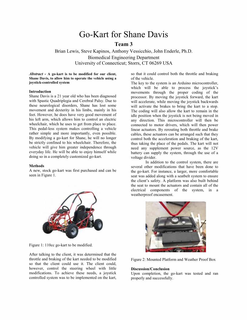
University of Connecticut; Storrs, CT 06269 USA Abstract - A go-kart is to be modified for our client, Shane Davis, to allow him to operate the vehicle using a joystick-controlled system Introduction Shane Davis is a 21 year old who has been diagnosed with Spastic Quadriplegia and Cerebral Palsy. Due to these neurological disorders, Shane has lost some movement and dexterity in his limbs, mainly in his feet. However, he does have very good movement of his left arm, which allows him to control an electric wheelchair, which he uses to get from place to place. This pedal-less system makes controlling a vehicle rather simple and more importantly, even possible. By modifying a go-kart for Shane, he will no longer be strictly confined to his wheelchair. Therefore, the vehicle will give him greater independence through everyday life. He will be able to enjoy himself while doing so in a completely customized go-kart. Methods A new, stock go-kart was first purchased and can be seen in Figure 1.
Figure 1: 110cc go-kart to be modified. After talking to the client, it was determined that the throttle and braking of the kart needed to be modified so that the client could use it. The client could, however, control the steering wheel with little modifications. To achieve these needs, a joystick controlled system was to be implemented on the kart,
so that it could control both the throttle and braking of the vehicle. The key to the system is an Arduino microcontroller, which will be able to process the joystick’s movements through the proper coding of the processor. By moving the joystick forward, the kart will accelerate, while moving the joystick backwards will activate the brakes to bring the kart to a stop. The coding will also allow the kart to remain in the idle position when the joystick is not being moved in any direction. This microcontroller will then be connected to motor drivers, which will then power linear actuators. By rerouting both throttle and brake cables, these actuators can be arranged such that they control both the acceleration and braking of the kart, thus taking the place of the pedals. The kart will not need any supplement power source, as the 12V battery can supply the system, through the use of a voltage divider.
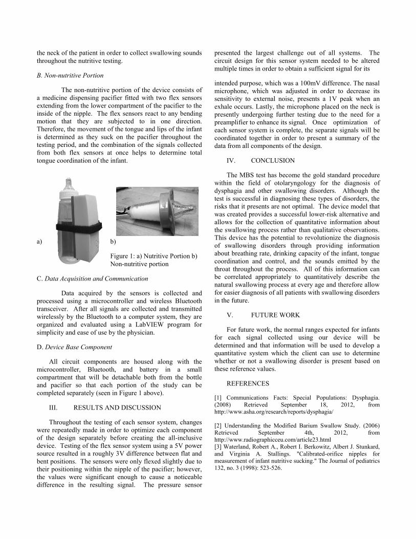
In addition to the control system, there are several other modifications that have been done to the go-kart. For instance, a larger, more comfortable seat was added along with a seatbelt system to ensure the client’s safety. A platform was also built behind the seat to mount the actuators and contain all of the electrical components of the system, in a weatherproof encasement.
Figure 2: Mounted Platform and Weather Proof Box
Discussion/Conclusion Upon completion, the go-kart was tested and ran properly and successfully.

Auditory and Visual Stimuli Board for Rapid Eye Movement Analysis
Team 3 Brian Lewis, Steve Kapinos, Anthony Vessicchio, Dr. John Enderle
Biomedical Engineering Department University of Connecticut; Storrs, CT 06269 USA
Abstract - The Auditory and Visual Stimuli Board we are building will allow our client, Dr. John Enderle, to further his research in diagnosing mild traumatic brain injuries using data from rapid eye movements. Introduction The board will be capable of producing visual and auditory stimuli at several different locations while being able to test eye movements at several different angles. Our device will consist of a large arched black board containing an evenly spaced out 11x7 matrix of LEDs and buzzers which serve as the auditory and visual stimuli sources. The design for our board is shown below in Figure 1.
Figure 1: Board Design Front View
Methods The key to our device is an Arduino microcontroller which has been programmed to activate the LEDs and buzzers in a sequence specified by our client. The Arduino allows us to activate each individual LED and buzzer at specific times and angles which will allow our client to accurately collect data in future testing. Our device will use standard EOG electrode placement to record rapid eye movements which makes our device a universal fit for all patients. Many of the components of our device have already been purchased by previous senior design teams and the remaining components are off the shelf products which will allow for us to stay under our budget. Discussion/Conclusion Although there are several types of concussion tests already on the market, many of the tests presently available involve running lengthy tests and rely on cognitive questionnaires. Dr. John Enderle is the first researcher to attempt to use fast eye movements as the determining factor for concussion diagnosis which will allow for more efficient and precise concussion diagnosis. Using data from fast eye movement testing will also allow for a quantitative diagnosis of concussions which will make future diagnoses more accurate. Over one million people a year are affected by concussions in the United States alone and there is a great need for a more efficient and accurate way to test for concussions. Once the device is complete, Dr. Enderle will be able to present the device to organizations in need of such a device such as the military and contact sports.

Modified Bottle for Dysphagia Diagnosis Team 4
Matthew Gajdosik1, Christine Mallek1, Alex Tansey1, Dr. Tulio Valdez2 Biomedical Engineering Department1
University of Connecticut; Storrs, Connecticut 06269 Connecticut Children’s Medical Center2; Hartford, CT 06106
Abstract— This design project presents an alternative method to the x-ray based radiological approaches used currently in diagnosing dysphagia. The device was designed with the capability of safely sampling a number of properties of the swallowing process non-invasively, in order to more easily diagnose swallowing problems without exposing the patients to radiation in the process. It includes both a nutritive bottle portion and non-nutritive pacifier portion which monitor liquid flow through the bottle, nasal breathing of the infant, sound emitted from the throat of the infant while swallowing, and the coordination of the tongue and lips while suckling and swallowing are performed. The device communicates wirelessly with a host application on any Bluetooth-compatible computer. By collecting a number of signals during swallowing and orienting them along a common axis, inconsistencies or weaknesses in the swallowing process of an infant can be identified.
I. INTRODUCTION
Dysphagia is a condition that involves difficulty swallowing, or a feeling that food is stuck in the throat or chest after eating. It is commonly found in adults, but can be diagnosed at any age, including in young children or infants. Children are often diagnosed as a result of certain genetic syndromes, maxillofacial deformities, or intellectual disabilities. As a result, a wide variety of symptoms can be associated with this disease and some of them include: painful swallowing, choking or coughing while swallowing, weight loss, aspiration, and chest pain [1]. These symptoms can be extremely uncomfortable and even life-threatening; therefore, it is crucial to get a correct diagnosis as early as possible. This is especially important in children who are unable to explain their symptoms or understand the potential problems.
The current technique for diagnosis of dysphagia is the Modified Barium Swallow (MBS) test. Testing with MBS has become the standard method of diagnosing all types of dysphagia associated with the upper portion of swallowing. It involves the patient swallowing mixtures of barium and food and then tracking the substance from the mouth to the stomach using radiation and X-ray imaging. As the x-ray process is done as a continuous film, exposure to x-rays is heightened compared to even a typical still-frame x-ray and
therefore it presents a higher risk of radiation exposure [2]. Additionally, barium is used to help improve the clarity of the image, and although it is safe to ingest, it has an undesirable taste that children do not enjoy.
As a result of the drawbacks and risks of this procedure, the client Dr. Tulio Valdez, a pediatric otolaryngologist at Connecticut Children’s Medical Center, proposed the development of an alternative diagnostic procedure. Therefore, a modified bottle and pacifier system was created which is capable of collecting quantitative data from the various subsystems involved in the swallowing process to produce an accurate diagnosis of dysphagia
II. MATERIAL AND METHODS
A. Nutritive Portion
The nutritive portion of the device (Figure 1a) consists of a baby bottle fitted with three types of sensors to collect information throughout the feeding process. The pressure exerted by the infant during the process of sucking and swallowing is measured through the use of a differential pressure sensor in coordination with a tubing system placed in the nipple of the bottle. A fluid-filled tube that is sealed on all but one end is connected from a pressure sensor in the closed end to a small exposed port at the tip of the nipple. During feeding, the forces placed on the nipple cause pressure to be transduced from the tip of the nipple to the transducer and provide information about pressures within the mouth and also fluid flow through the nipple [3].
Two microphones are also incorporated into this portion of the device in order to provide information about both breathing rate and swallowing sounds during the feeding process. A unidirectional electret condenser microphone is attached to the top of the bottle and directed under the nose of the infant in order to detect their breathing rate throughout testing. This provides an accurate measurement of their breathing rate because infants complete obligate nasal breathing for the first several months of their lives. An omnidirectional electret condenser microphone also extends from the bottle and is mounted to
the neck of the patient in order to collect swallowing sounds throughout the nutritive testing.
B. Non-nutritive Portion
The non-nutritive portion of the device consists of a medicine dispensing pacifier fitted with two flex sensors extending from the lower compartment of the pacifier to the inside of the nipple. The flex sensors react to any bending motion that they are subjected to in one direction. Therefore, the movement of the tongue and lips of the infant is determined as they suck on the pacifier throughout the testing period, and the combination of the signals collected from both flex sensors at once helps to determine total tongue coordination of the infant.
a) b)
Figure 1: a) Nutritive Portion b) Non-nutritive portion
C. Data Acquisition and Communication
Data acquired by the sensors is collected and processed using a microcontroller and wireless Bluetooth transceiver. After all signals are collected and transmitted wirelessly by the Bluetooth to a computer system, they are organized and evaluated using a LabVIEW program for simplicity and ease of use by the physician.
D. Device Base Component
All circuit components are housed along with the microcontroller, Bluetooth, and battery in a small compartment that will be detachable both from the bottle and pacifier so that each portion of the study can be completed separately (seen in Figure 1 above).
III. RESULTS AND DISCUSSION
Throughout the testing of each sensor system, changes were repeatedly made in order to optimize each component of the design separately before creating the all-inclusive device. Testing of the flex sensor system using a 5V power source resulted in a roughly 3V difference between flat and bent positions. The sensors were only flexed slightly due to their positioning within the nipple of the pacifier; however, the values were significant enough to cause a noticeable difference in the resulting signal. The pressure sensor
presented the largest challenge out of all systems. The circuit design for this sensor system needed to be altered multiple times in order to obtain a sufficient signal for its
intended purpose, which was a 100mV difference. The nasal microphone, which was adjusted in order to decrease its sensitivity to external noise, presents a 1V peak when an exhale occurs. Lastly, the microphone placed on the neck is presently undergoing further testing due to the need for a preamplifier to enhance its signal. Once optimization of each sensor system is complete, the separate signals will be coordinated together in order to present a summary of the data from all components of the design.
IV. CONCLUSION
The MBS test has become the gold standard procedure within the field of otolaryngology for the diagnosis of dysphagia and other swallowing disorders. Although the test is successful in diagnosing these types of disorders, the risks that it presents are not optimal. The device model that was created provides a successful lower-risk alternative and allows for the collection of quantitative information about the swallowing process rather than qualitative observations. This device has the potential to revolutionize the diagnosis of swallowing disorders through providing information about breathing rate, drinking capacity of the infant, tongue coordination and control, and the sounds emitted by the throat throughout the process. All of this information can be correlated appropriately to quantitatively describe the natural swallowing process at every age and therefore allow for easier diagnosis of all patients with swallowing disorders in the future.
V. FUTURE WORK
For future work, the normal ranges expected for infants for each signal collected using our device will be determined and that information will be used to develop a quantitative system which the client can use to determine whether or not a swallowing disorder is present based on these reference values.
REFERENCES
[1] Communications Facts: Special Populations: Dysphagia. (2008) Retrieved September 18, 2012, from http://www.asha.org/research/reports/dysphagia/
[2] Understanding the Modified Barium Swallow Study. (2006) Retrieved September 4th, 2012, from http://www.radiographicceu.com/article23.html [3] Waterland, Robert A., Robert I. Berkowitz, Albert J. Stunkard, and Virginia A. Stallings. "Calibrated-orifice nipples for measurement of infant nutritive sucking." The Journal of pediatrics 132, no. 3 (1998): 523-526.

Integrated Vital Signs Monitor Team 5
David Knoff, Jacob Adams, Maysarah Shahabuddin, John Enderle Ph.D, Krystyna Gielo-Perczak Ph.D Biomedical Engineering Department
University of Connecticut, Storrs, CT 06269 USA
Abstract -The Vital Signs Monitor will be an effective way of monitoring multiple signals from the patient, at home or in the clinic/hospital, through a single, simple device apparatus that wirelessly transmits data to a mobile tablet for processing and ease of use. Currently, there is no such singularly wireless device that acquires this multitude of signals including blood oxygen level, core body temperature, ECG, EMG, motion detector (for falls), respiration/heart rate, and patient’s weight. For this project, we will combine as many of these data collection devices as we can for ease of access, safety, and portability to provide for patients with little to no clinical expertise as well as providing clinicians benefits from this system by monitoring their patients in an effective manner. Our end goal is for this Vital Signs Monitor to be an inexpensive yet powerful solution for our potential customer’s uses.
Keywords-vital signs, ECG, wireless sensors, fall detection, blood oxygen, respiration, core body temperature, stethoscope
I. INTRODUCTION The goal of this project is to provide nonmedical
personnel with the ability to obtain a great array of commonly needed signals that the body provides. This comprehensive point of view can then be sent to a doctor and used to keep track of a patient’s health in a manner that does not require constant supervision. Another benefit to this method is that the patient can also continue on their day, eliminating the need for an expensive visit to the doctors, as well as capturing a more accurate glimpse into the body during the daily life of a patient. Finally the presence of automated sensors reduces the need for in-home nurses, and hopefully will lower the costs of obtaining all the important measurements for anyone who needs them.
Many patients cannot spend the money or the time needed to obtain all of the data for such an extensive set of observations. Also, current monitors are bulky and contain many wires, which both cause hazard to the patient and people using them. Our design is going to be mobile therefore size and weight must be accounted for. These limits the patient’s accessibility to such care, and in many cases, the availability of up to date and accurate information on demand on the part of the doctor can result in many mistakes and faulty diagnoses of a patient. On the other side of the health problem, during rehabilitation and recuperation, if the proper care is not observed, there may be issues that can return the patient to a state of illness. This
device would introduce the concept of minimal upkeep and observation on the doctor’s part to ensure the proper actions are taking place. The Vital Sign Monitor will provide consolidated, continuous, and archived reports of the patient’s health status for the use of the patient, nurses, physicians, and any future caretaker. This allows the patient’s history of vital signs to be analyzed as the patient progresses through certain health conditions, rehabilitation or just normal life. Each vital sign is important in monitoring the patient’s health as well as the ability to call for aid if needed.
II. DESIGN METHODS
A. Chest Strap Design The chest strap is intended to be a comfortable,
adjustable strap with 4 open leads. The sensors will use pins to align and connect to the 4 leads in order to sit in position and collect data. The 4 leads will correspond to the voltage source, 5 volts, a clock line and a data line, both needed for I2C communication, and a ground. Each of the sensors will be designed to draw a small amount of power for their continuous operation while waiting for a data request, and then only turn on the bulk of their collection instruments when the data is requested.
Figure 1: Chest Strap Design

B. Master Controller The master controller will have three separate sections
behind the theory of operation. The first and most prominent division will be the master controller for the I2C communication protocol. This will be responsible for collecting and maintaining all the relevant data signals in its local memory. The second division will be the emergency data portion using SPI communication. The third section of the master control unit will be the Bluetooth communication antenna. Since this is where all of the data from sensors will be kept, this is also the location responsible for sending the data to a computer running LabVIEW.
C. Biosensors Body Temperature:
The body temperature biosensor will take a reading of the patient’s body temperature from inside their armpit upon request from the master controller. Current will run through the NTC thermistor and based on the voltage drop across the element, the LabVIEW program will make calculations and output the patient’s measured body temperature. The circuit construction of the body temperature biosensor ensures the least amount of error by eliminating lead wire noise using a 4-wire Wheatstone bridge. Blood Oximetry
The pulse oximeter will clip directly to the chest strap, but will have a smaller clip containing a photo sensor and two LED‟s to clip onto the ear. The cord will be long enough so that this will not hamper the subject’s range of motion. The master controller will request data from the sensor which will then briefly turn on the lights long enough to get an absorbance. Then the absorbance will be sent to the LabVIEW program and the ratio of oxygenated to de-oxygenated blood will be calculated to obtain the blood oxygen content. Fall Detection
The fall detection biosensor will have the capability to detect a patient’s static and dynamic acceleration using the ADXL345 triple axis accelerometer. When the patient’s acceleration reaches or exceeds the programmed threshold acceleration in any of the three axes, the accelerometer will alert the LabVIEW program. Stethoscope
The stethoscope we have chosen to use is the electronic stethoscope developed by Chad Lyons. This sensor will be used for the observation of heart and lung sounds, including respiration rate. We built a circuit to amplify, filter, and shift the phase of the signal. Due to issues raised by Dr. Lyons however, the use of a single stethoscope will be limited by the adhesion properties of the patch, and thus the sensor clip will come built in with the ability to quickly swap out the patches as needed. ECG
The ECG biosensor will utilize a 12 lead system plugged into a TI ADS1298RECG-FE front-end performance demonstration kit. This circuit board amplifies and filters
the signal, exporting the data to a LabVIEW based TI software program. Our master LabVIEW program will call the TI software as an executable file when the ECG option is selected. Weight
Patient’s weight is an important aspect to their overall health, as obesity can cause serious health concerns. Their weight will be monitored through a separate apparatus from the overall device but will still communicate via Bluetooth to the user-interface. Not only will this data be displayed to the user but it will log this data day to day or whenever the patient weighs them. Bluetooth enabled scales already exist in the market, which we will use. Blood Pressure
Blood pressure is another majorly important aspect to the vitals of any patient as any sudden drop in blood pressure can mean heart failure and cause death. In order to monitor this signal, a blood pressure cuff is required to be worn on the arm which will periodically take data and transmit it via Bluetooth. LabVIEW Programming
National Instruments: LabVIEW programming software is an important aspect to this device. LabVIEW has fantastic, easy user display, as well as superior data analysis collection and processing. Bluetooth sub-programs in LabVIEW aid in this process of data collection wirelessly to implement portability. Also, LabVIEW has multiple functions in analyzing many types of data from waveforms to arrays and clusters which can be manipulated to display the user’s vital signs.
III. CONCLUSION This vital signs monitor will monitor blood pressure,
blood glucose level, heart rate, respiration rate, body temperature, blood oxygen level, heart and lung sounds through a stethoscope, weight and fall detection. This device is portable and has the ability to monitor vital signs comfortably in a variety of settings including during exercise, daily tasks, sleep, and many other activities.
ACKNOWLEDGMENT A special thanks for guidance and advice from Sarah Brittain, Dave Kaputa, Tom Capuano, and Chad Lyons.
References
"Arduino - Wire Reference Library." Arduino - Wire. N.p., n.d. Web. 03 Oct. 2012. http://www.arduino.cc/en/Reference/Wire “Pulse oximeter accuracy.” Jyotirmoy Das. Web. Nov. 2010. http://www.ncbi.nlm.nih.gov/pmc/articles/PMC3016573/ “Principles of Pulse Oximetry Technology.” Web 10 Sept. 2002. http://www.oximetry.org/pulseox/principles.htm “Sleep disorder monitoring using the Arduino.” Web 10 Aug, 2011. http://medicarduino.net/?tag=pulse-oximeter http://www.withings.com/en/wireless-scale/feature

Design of an EndoClip III 5 mm Firing Fixture Team 6
Viraj Matieda1, Joseph Decker1, Christopher Thibeault1, Brian Creston2, John Enderle Ph.D 1Department of Biomedical Engineering University of Connecticut, Storrs, CT 06269
2Covidien, 195 McDermott Rd, North Haven, CT 06473
Abstract— The EndoClip III Firing Fixture for Covidien will revolutionize how they test and experiment with the EndoClip III hand held device. The EndoClip III is used in laparoscopic surgeries to apply titanium clips around vessels, thereby, closing them off and stopping the organ from receiving vital fluids[1]. During testing, the company hand fires the device onto porcine aorta, resulting in the production causing numerous variables to flourish. First off, there isn’t a uniform force or linear distance applied to the trigger handle with each pull. With the way the EndoClip III functions, this could mean some clips aren’t fully pinched to their maximum flatness. With sample testing of twenty or more, these variables can cause large deviations in the parallel and perpendicular pull test data once it is compiled. So in an effort to solve this, the design is going to move away from hand testing and make a fully automatic firing fixture that can run two different tests repeatedly with great accuracy, thereby eliminating human error. The EndoClip III Firing Fixture was designed to apply 0 to 50 pounds of force at 0.2 lb increments to the trigger handle during the force test, and 0 to 5 inches of linear travel at 0.05 inch increments to the trigger handle during a linear distance test.
I. INTRODUCTION As a company, Covidien manufactures many types of surgical clip appliers which are fire titanium clips oftentimes used to block various vessels in the body. What is even more important than the clips just blocking the vessels, is that they remain secure to the vessel otherwise postoperative problems could occur. The test that Covidien uses on the EndoClip III is to measure the force that is needed to remove a clip from a vessel both along the axis of the vessel and perpendicular to the axis of the vessel. Up to this point all of the firing of the Endo Clip III during testing has been done via hand firing. By using hand firing as the firing method, human variation is introduced into the equation. The creation of a device that fires the EndoClip III at a consistent force as well as a consistent distance will help reduce this variation. The hope is by reducing variation there will be an increase in accuracy, as well as a reduction in the number of samples required for testing the amount of time it takes for testing to occur.
II. METHODS & MATERIALS
A. Mark-10 Motorized Test Stand Model ESMH The Mark-10 company makes many different models of test stands. For our purposes, we chose a horizontal ESMH
model because it fit into the plans for Covidien to use it in the assembly line to replace the manual, geared model they are already using. With the addition of the digital force gauge series 5 and the digital travel display we will be able to create a firing fixture that can accomplish both the distance test and the force test. The chosen Mark-10 motorized test stand is a horizontal machine that runs linear tension, compression and coefficient of friction testing. It features integrated limit switches which makes numerous repetitive tests a possibility at an inputted maximum value. This is in an effort to lower the standard deviation and create a new device that fires exactly the same way each time you apply the same distance pull on the trigger and during the application of the same force. Before either test is run, both the force gauge and the distance sensor need to be tared to create uniformity. Through the use of the digital force gauge series 5, we can input a desired applied force and then turn the knob to the speed desired. When the desired force is applied to the trigger handle, the test stand will beep and stop the motor from travelling any more. The distance test will be different in that the engineer will be fully in control of the experiment. He/she will again tare the digital distance sensor and turn the knob on the remote control unit to start the internal motor travelling linearly. While it is moving, the engineer will need to watch the distance sensor and when the required linear travel is being approached, he/she can turn the knob the other way to slow the motor and then stop it when the desired distance is met. The Mark-10 model ESMH has some key features that bear mentioning. The motor housing within the test stand that runs linearly along a steel bar can apply a maximum force of 50 pounds. It can also travel linearly up to 13 inches (330 millimeters) with the motor having a speed range of 0.2 to 50 inches per minute (5 to 1270 millimeters per minute). The speed accuracy with this test stand is +/- 5% of the setting and has +/- 0% variation with the load. The benefit of choosing this model is that it contains a limit switch repeatability that has +/- 0.001 inches (0.03 millimeters) capability and the beneficial remote control console comes with a 3 foot (1 meter) cable to put the distance the experimenter can stand away from the test stand into perspective. Within the test stand there is an 80 to 250 VAC universal power supply running the entire device.

B. Mark-10 Advanced Digital Force Gauge Series 5 The Mark-10 advanced digital force gauge is used with the ESMH motorized test stand. It is essential for this project to use the force gauge. The force gauge is able to fit right onto the top of the Mark-10 ESMH motorized test stand and gives a real time display of the current force which is being applied to the EndoClip III 5mm. The Series 5 model can even control the ESMH so that once a certain force is reached it will stop moving. The force gauge has an accuracy of +/- 0.1% of full scale +/- 1 digit and it can go up to a force of 100 lbs by increments of 0.2 lbs. The sampling rate is 7,000 Hz for the force gauge. The force gauge is powered by a rechargeable battery or AC and once the battery is too low, it will automatically shut off. The battery life of the force gauge is 7 hour of continuous use if the backlight is kept on and 24 hours of continuous use if the backlight is kept off. At the base of the force gauge is a threaded knob that actually is responsible for measuring the compression force. For the contact point between this threaded knob and the trigger handle itself a cup fixture was created. The side of the fixture that makes contact with the trigger is lined with felt in order to not damage the trigger of the EndoClip during the firing process.
C. Digital Travel Display The digital travel display is a part that comes as an option
with the ESMH motorized test stand. This is a part that was critical for the project because one of the requirements is for the client to be able to see the distance that the EndoClip III 5 mm trigger has moved. The digital travel display will allow the ESMH to display the distance in real time. It can travel up to 12 inches which is more than enough because the client only needs up to 5 inches of horizontal distance travel. The travel display shows distance in inches but it can also be switched to millimeters. It is attached to the side of the ESMH and it can move forward or backwards. Having the upper and lower limit switches on the device is a important because the client wants to be able to stop the trigger at a certain distance. Having limit switches on the firing device allows the client to be able to do that.
D. EndoClip III 5 mm Plastic Mold The devcon mold is used to hold the Endo Clip III 5 mm
in place during testing. The four holes in each corner are used to mount the mold to the base. This is to ensure that the
Figure 1: Mold Holding EndoClip III 5 mm
mold does not move at all when the trigger is being pressed. The mold is used in conjunction with the clamp to secure the EndoClip III during testing to prevent lateral and vertical movement which will invalidate results. A picture of the mold with the EndoClip III 5 mm can be seen below.
E. Clamp for EndoClip III 5 mm The clamp that is being used is a dual action clamp
because of its lever action. When pulled back on the lever it lifts the shaft holding the plastic piece that pins the EndoClip III in place. When you push the lever towards the shaft, it pushes the shaft down onto the EndoClip III body and then locks it in place. In addition, the clamp will prevent the movement of the EndoClip III in the vertical direction as the trigger handles is suppressed.
III. RESULTS AND DISCUSSION After numerous trials and testing, it was determined that the firing fixture for the EndoClip III could accurately complete both the force and distance tests to a very precise degree. It was required that the firing fixture be able to apply 0 to 50 pounds of force at 0.2 increments to the trigger handle during the force test, and 0 to 5 inches of linear travel at 0.05 increments to the trigger handle during a linear distance test. The Mark-10 model ESMH is able to travel up to 13 inches linearly at measurable increments of 0.0005 inches greatly surpassing the requirement. It can also apply up to 100 pounds at increments of 0.01 pounds of force again eclipsing the specifications.
Figure 2: EndoClip Firing Fixture Design
ACKNOWLEDGEMENTS [1] Brian Creston and Tom Zammataro, Covidien [2] Dr. John Enderle and Katelyn Burkhart, BME Dept. [3] Serge Doyon and Peter Glaude, Machine Workshop
REFERENCES [1] "ENDO CLIP™ III Clip Applier with Clip Logic Technology." ENDO CLIP™ III 5mm Clip Applier. Covidien, n.d. Web. 17 Apr. 2013.
Test Stand Distance Sensor
Force Gauge Mold
Digital Controller

Tissue Thickness Measurement Device Team 7
David Connolly; Brian Osborn; Mark Jones: John Enderle, Ph.D. Department of Biomedical Engineering,
University of Connecticut; Storrs, CT 06269 USA
Abstract-The objective of this project was to design a device that would measure tissue thickness in a reliable and accurate manner. This novel device utilizes a digital caliper allowing R&D engineers to more accurately measure tissue thicknesses as compared to predicate technology. Our clients expected a stronger closing force (40 N), improvements to the ergonomic design, a controlled rate of closure (<10s/inch), a continuous digital output (±0.005” accuracy), and a method for determining the initial uncompressed tissue thickness.
I. INTRODUCTION Covidien is a global leader in the medical device field
with its global headquarters located in Mansfield MA. Per request of the North Haven CT campus, Team 7 worked to design an improved tissue thickness measuring device. Covidien’s Research and Development Department currently uses an electronic caliper designed by a University of Connecticut Senior design team from a previous year. One of Covidien’s products is a family of stapling devices frequently employed to appose tissue in numerous types of surgical applications. Different size staples are available to allow apposition of different thicknesses of tissue, and selecting the appropriate size staple for an application is important to ensuring viability of the staple line. The purpose of this design project is to create an improved tissue thickness measuring device that maintains the functionality of previous features but is more ergonomic, includes a stronger closing force, and outputs the data continuously. The device will maintain its portability, light weight, precise measurement range, as well as other attributes. The main improvements that we will add to this are a controlled rate of closure, a method for outputting and displaying data, and a determination of the point of tissue contact to take initial uncompressed tissue measurements.
II. SPECIFICATIONS This tissue thickness measuring device must be capable
of measuring initially uncompressed sample thicknesses, and final compressed sample thicknesses ranging from 0.050 to 1.000 inches with an accuracy of ± 0.005 inches. The device must have a controlled rate of closure. It must also record thickness at initial tissue contact until final compression. In addition to these operational specifications, the following technical specifications were met. The material that was used for the housing containment was Aluminum 6061. The design was created such that the operator would be able to use the measurement device in one hand comfortably. The
design was considerate of the fact that the caliper will be cleaned by method of autoclave. The device is operable at temperatures over 137 degrees Celsius. The device has a data output feature that allows the user to save measurements to a USB 2.0 Flash-drive. A user interface was created through LabVIEW such that the operator can determine the initial measurement time till closure, and sample modulus. The required operating system is Windows 8/Vista/XP. The required processor is a Pentium 4. The required memory is 512 MB of RAM. The proper cleaning method requirements are that it can be cleaned without being damaged or resulting in a loss of calibration or accuracy. The caliper must be able to be autoclaved or washed by a steam wash. Therefore the device must be waterproof. It must also be able to withstand pressures of 0.0 to 1.0 atmospheres.
III. DESIGN CHOSEN The overall design of the improved tissue caliper was
modeled after previous years design. The caliper used was a Mitutoyo model that is water proof. In order to meet specifications given to us by our client at Covidien, we used a magnetic spring that will apply a constant force as the caliper head closes on the tissue being measured. Custom jaw head attachments were created to place on the calipers jaw head. These attachments were created with specific surface area in order to create a pressure of 8 grams/mm2. In previous year’s designs, the tissue caliper would snap closed on the tissue abruptly. In order to correct this problem, we created a pneumatic system that works to limit the rate of closure of the caliper jaw heads. This was done by creating an air tight cylinder with a bleed valve. The plunger of the cylinder is linked to the shaft which drives the caliper jaw heads open and closed. The caliper’s closing rate is limited by the rate at which air can leak out of the system. In order to keep the weight of the device under the 4 pound maximum, all parts were made out of either Aluminum 6061 or SLA prototype polymer. The jaw attachments, electronics housing, and electronics housing cap was made out of polymer because it is insulating and would not conduct electricity. Using SLA parts would not be sufficient for all parts. The Aluminum was used instead in order to increase the lifetime of the product. The electronic housing was made with a removable cap in order to change the 9 V battery as necessary. The electronic housing is secured using small screws. An image of the assembly can be seen in Fig. 1.

Figure 1. The assembly of the device drawn on Solidworks.
IV. CIRCUITRY Included in the specifications was the requirement for the
device to record and save displacement data for analysis of physical properties of the tissue being compressed. To achieve this goal, a system was designed that would begin data recording of displacement at a rate of four readings per second (a reading at every 250 milliseconds). The system is triggered by the compression of two ultra-sensitive Panasonic EVQQ2 series buttons located on the caliper jaws. Once a signal has been received that the two buttons are pressed, the displacement data is sent via a Mitutoyo 06ADV380A USB cable to an onboard storage device located on an Atmel USBKEY 2 development board. The development board was programmed with LUFA (Lightweight USB Framework for AVRs) to be used as both as a USB mass storage device when connected on a computer as well as a host for a keyboard with parser. The freeware FatFS was used as a means of a file system on the development board. The displacement data are stored on the device in the form of a ‘.txt’ file.
Figure 2. Atmel USBKEY2 development board.
V. LABVIEW Once the data has been captured, a custom LabVIEW
program is used to extrapolate physical data from the displacement data on the caliper. The program shows three
graphs including Displacement vs. Time, Stress vs. Strain, and Force vs. Displacement Graphs. In addition to the graphs, the following information is displayed: initial/final displacement values, time displacement, and Young’s Modulus. This program comes with an installer and can be used on computers running Microsoft Windows XP or newer.
Figure 3. LabVIEW program front panel.
VI. CONCLUSION Our design was successful in measuring samples and will
be sent to our clients at Covidien for their approval. Testing was done at our group’s lab station on the Storrs campus and adjustments to the design were made until we were satisfied that the device met our desired specifications.
VII. ACKNOWLEDGMENTS We would first like to thank our faculty advisor, Dr. John
D. Enderle Ph.D. for his help and suggestions during the weekly meetings. We would also like to thank our teaching assistant, Sarah Brittain for her help during these meetings as well and for her input on the project. We would like to thank Dave Kaputa for helping us troubleshoot our website and setting up the computers in our lab. Finally we would like to thank our client and sponsors for this project from Covidien: Jennifer Whiffen, Dwight Bronson, Marisha Godek, and Mark Buchter. We would like to thank them for sponsoring this project and for their help in the design of our prototype.
VIII. REFERENCES 1."ABSOLUTE Coolant Proof Caliper Series 500 with Dust/Water Protection Conforming to IP67 Level." ABSOLUTE Coolant Proof Caliper Series 500 with Dust/Water Protection Conforming to IP67 Level. Mitutoyo, Jan. 2008. 2."AVR287: USB Host HID and Mass Storage Demonstration." Atmel. N.p., Sept. 2009. Web. Feb. 2013. 3.MagSpring – Magnetic Springs. LinMot Inc., Mar. 2012.

Clip Gap Specification Project Team 8
John Burke1, Kathryn Dobler1, and Jordy Schuller1, John Enderle Ph.D1, Emily Davis2, Eric Tayle2
1 Biomedical Engineering Department University of Connecticut, Storrs, CT 06269 2Covidien, 195 McDermott Rd, North Haven, CT 06473
Abstract—This project has aimed to create a test fixture and test method to test the clips used in Covidien’s Surgiclip S-9.0. The entire system is broken apart into two main components; a simulated blood flow system and a clip applying system. The simulated blood flow system uses a syringe pump (with water) and synthetic tubing to simulate a range of blood pressures that occur in human veins. The clip applying system uses an instron device and a fixture, created out of stainless steel and designed by our team that closes the clips with varying displacements. Our entire system is controlled through a LabView interface. The LabView interface allows for the user to easily control the system and collect the necessary data.
I. INTRODUCTION Covidien is a leading medical device company in surgical
wound closure and hemostasis products. They have developed a clip applier, the Surgiclip S-9.0, that applies small titanium interlock clips onto tubular structures such as vessels. The Surgiclip is a single use automatic clip applier that comes with 20 loaded clips for surgery and is disposable after use. The titanium clips are meant for a more secure fixation of clip to tissue providing greater ligation security. The Surgiclip S-9.0 is Covidien’s smallest clip applier device. The device uses clips that are 2.25 mm in size with a closed length of 3.7 mm. This means that the vessels used for these clips are less than 2.5 mm.
Covidien is looking for a method to test the clips in this device that will create repeatable clip gap sizes. When a clip is closed (as shown in Figure 1) there is a minimum gap, maximum gap, and eyelet. Covidien has a current device that allows them to measure the clip gaps but the need a fixture that is able to replicate the closing of the clips in a similar matter as the device while collecting displacement and force data. Covidien is also looking to close the clips onto synthetic tubing that is able to simulate a range of blood pressures that occur in humans.
Figure 1. Titanium clip used in Surgiclip S-9.0 when closed.
II. SYSTEM The entire system is broken into two main parts; the
simulated blood flow system and the clip applying system.
A. Simulated Blood Flow System The simulated blood flow system is comprised of a
syringe pump, synthetic tubing, pressure sensor, a National Instruments DAQ board, and finally numerous leurs and stop-cocks. A diagram is shown below in Figure 2 that displays the entire system, including the clip closing fixture and laptop.
Figure 2. Entire system including laptop, instron, clip closing device and simulate blood flow system.
When running, the syringe pump runs at 20 mL/hour
through both of the syringes. The water flows together through a T-junction and passes through a pressure sensor that outputs the pressure in the LabView program. The pressure sensor uses the National Instruments DAQ board, in the plastic casing next the the instron device and laptop (red arrow), to acquire the data and output the pressure to the LabView program.
The water flows through the tubing (which is thicker in all sections except between the clip closing fixture) until it reaches the stop-cock. The DAQ board is enclosed in plastic casing to protect the electronics in case anything bursts and there is a water leak. When the desired pressure is reached in the tubing the syringe pump is stopped while a clip is closed onto the tubing. If hemostasis (stopped blood flow) has

occurred in the tubing after a clip is fired then when the stop-cock is released the pressure should remain constant and not drop off.
The water is pushed from the syringe pumps at a slow rate to ensure that the tubing does not burst or fall of the leurs. Rubber washers and sutures are used to prevent leaks and ensure that the tubing stays on the leurs. Water is dispensed into a tube and finally out into a plastic beaker.
B. Clip Applying System The clip applying system integrates an instron 3344
device and a stainless steel device that has been designed by our senior design team and built by the machine shop at Covidien. The device (as shown below in Solidworks form in Figure 3) implements the channel and jaw used in the Surgiclip S-9.0 and allows the user to interchange the jaws and channel when necessary. The channel sits in the two bars across the fixture securely and the jaws are attached to the middle block through two pins.
Figure 3. Clip closing fixture shown in Solidworks form. The instron device clamps down onto the middle block
and pulls the block up, which in turn pulls the pins and jaws up through the channel, and closes the clip. The device includes the two bars that hold onto the tubing to allow the tubing the flow through the jaws perpendicular to the jaws and also to move up at the same rate as the jaws. This ensures that the clip is closed onto the tubing at the correct position.
The base of the fixture includes two posts that holds the entire fixture together. The bars are fit tightly into the two posts and the posts screw down into the base. The base has 4 separate holes that allows the user to screw the base down onto the instron device. This ensures that the fixtue does not move during testing.
C. LabView Interface with Bluehill 2 The entire system is interfaced through LabView 12 as
shown below in Figure 4. The system requires Bluehill 2 to control the instron device but the Labview program is able to control Bluehill 2 and also output the data from the pressure sensor at the same time. During testing, the user must first open up Bluehill 2 and then input the desired clip closing extension and rate of extension into the program. When the program is started the program will output the pressure of the pressure sensor and ask the user to input the test name. The user is able to test repeatedly while keeping the program on and outputting the pressure. At the end of each test the program displays the displacement and force data for each test.
Figure 4. LabView program front panel for clip closing system. As previously stated, hemostasis occurs in the simulated
blood flow system if, after the clip is applied, the pressure is maintained in the tubing. The project allows the user to test clips at different displacements until hemostasis is reached and repeat the testing numerous times at the same displacement.
ACKNOWLEDGMENT Acknowledgement should be given to Emily Davis and
Eric Taylor at Covidien Surgical Solutions, Inc. Acknowledgement is also given to the machine shop at Covidien for building the clip-closing fixture. Acknowledgement should also be given to Dr. John Enderle, Joseph Calderan, and finally Dr. Dave Kaputa for their help throughout the year on the project.
Design of a Laparoscopic Trocar Duckbill Seal Fixture Device
Team 9 Omkar Betageri1, Jacob Baril1, Andrew Garofalo1, Christopher Evans2, Greg Okoniewski2, Krystyna
Gielo-Perczak1, Ph.D. 1University of Connecticut, Department of Biomedical Engineering, Storrs, CT 06269
2Covidien, North Haven, CT 06473
Abstract—This project involves design and testing of a laparoscopic trocar duckbill seal fixture device. The trocar is an instrument used for insertion of instruments into the body cavity. The duckbill seal is housed within the trocar and required to ensure that the trocar does not leak any CO2 to the environment throughout the surgical procedure. The device will determine the duckbill seal efficiency through seal response testing. The testing procedure will involve pneumatic components to simulate an insufflated body cavity during surgery and removal of instruments. Electrical components will be used to record flow rate data through duckbill seal and conduct statistical analysis. Overall the device will quantify the efficiency of duckbill seals through closure response testing.
I. BACKGROUND In laparoscopic surgery, the surgeon utilizes a small (5-15
mm), minimally invasive incision to perform an operation within the patient’s abdomen. In order to create sufficient working room through the small incision, the surgeon induces pneumoperitoneum, or inflation of the abdominal cavity with CO2. After insufflation, the instruments required for the procedure are inserted into the abdominal cavity through a hollow, cylindrically shaped device called a trocar. The trocar assembly and surgical instruments in the laparoscopic surgical site are shown in Figure 1.
Figure 1: Trocar and Laparoscopic Surgery [1]
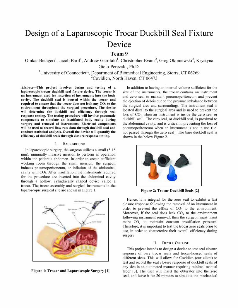
In addition to having an internal volume sufficient for the size of the instruments, the trocar contains an instrument and zero seal to maintain pneumoperitoneum and prevent the ejection of debris due to the pressure imbalance between the surgical area and surroundings. The instrument seal is located distal to the surgical area and is used to prevent the loss of CO2 when an instrument is inside the zero seal or duckbill seal. The zero seal, or duckbill seal, is proximal to the abdominal cavity, and is critical in preventing the loss of pneumoperitoneum when an instrument is not in use (i.e. not passed through the zero seal). The bare duckbill seal is shown in the below Figure 2.
Figure 2: Trocar Duckbill Seals [2]
Hence, it is integral for the zero seal to exhibit a fast
closure response following the removal of an instrument in order to prevent the efflux of CO2 to the environment. Moreover, if the seal does leak CO2 to the environment following instrument removal, then the surgeon must insert more CO2 to maintain constant insufflation pressure. Therefore, it is important to test the trocar zero seals prior to use, in order to characterize their overall efficiency during surgery
II. DEVICE OUTLINE This project intends to design a device to test seal closure
response of bare trocar seals and trocar-housed seals of different sizes. This will allow for Covidien (our client) to test and record the seal closure response of duckbill seals of any size in an automated manner requiring minimal manual labor [3]. The user will insert the obturator into the zero seal, and leave it for 20 minutes to simulate the mechanical

stress of surgery. Then, the user is required to place the trocar on the testing apparatus and affix the seal to the apparatus using the appropriate fixture seal. If a trocar-housed seal is being tested, an aluminum and rubber ring fixture specific to the diameter of the bare trocar seal will be used. An additional rubber ring is threaded and screwed to the testing chamber to create an air-tight seal. If a bare seal is tested, then a similar aluminum and rubber ring fixture is used. The bare seal fixture uses a Plexiglas inner ring in order to fix the seal tightly to the fixture. These seals are required for maintaining a closed testing system, so that no insufflation pressure leaks through the seal during the test. At this point, shop air will be used to pressurize the testing chamber, in order to mimic the condition of pneumoperitoneum during surgery. Afterwards, upon pseudoscope actuation, the seal will fully close around the pseudoscope segment, allowing zero air flow through the seal. The ring stand can adjust the actuator height to a specific level above the seal which decreases the length of the actuator extending into the seal during actuation. This will decrease the amount of time required for the actuator to disengage with the seal during seal closure and more thoroughly measure flow rate during seal closure. A SolidWorks drawing of the device is shown in Figure 3.
Figure 3: Duckbill Seal Test Fixture Device Once the signal is sent to begin pseudoscope retraction, a
solenoid will switch the air input to the insufflation air tank. As the pseudoscope disengages with the duckbill seal, air will leak out of the seal, decreasing the pressure in the testing chamber [4]. This will create a pressure gradient between the insufflator tank and testing chamber, and lead to the influx of air from the higher pressure air tank into the lower pressure chamber. Thus, as the flow rate out of the seal decreases, the pressure gradient between the chamber and air tank decreases, and flow will cease. Since the flow meter will connect the insufflation tank to the testing apparatus, it will effectively measure the closure response of the seal. The flow meter will provide readings with a high sampling rate, such that a clear decrease in flow rate can be determined. The data will be collected in real-time using a
LabVIEW program running on a mini PC located on the device. A small touch screen will be located on the PC, allowing the user to monitor the recording of data onto the VI. Afterwards, this data can be imported into a Minitab program on the PC for statistical analysis. Additionally, the device will contain a holder rack for multiple trocars, and will house the pressure tank. Furthermore, the device will be lightweight (less than 60 lbs), and contain safety precautions such as an emergency stop button and a covered testing area. The testing chamber contains a flat Plexiglas door to allow for motion capture of seal response. The inside of the testing chamber is illuminated with four LEDs for increased visibility during motion capture. The PSPICE circuit diagram for the LED light is shown in Figure 4.
Figure 4: LED Circuit for Testing Chamber The testing chamber also contains a pressure release
valve that can be pulled to release air from the chamber. The chamber has a port which connects wiring and tubing from the testing chamber.
III. CONCLUSION Overall, the purpose of the device is to provide Covidien
with a faster and more reliable device to test the seal closure response of zero seals in trocars of various sizes.
IV. REFERENCES [1] "Laparoscopy." Laparoscopy. Selva's Fertility, Obstetrics,
and Gynaecology Clinic, 2013. Web. 18 Apr.2013.<http://www.melakafertility.com/laparoscopy.shtml>
[2] Yngve, Aron. "Trends in Laparoscopy: Sealing Technology." Trends in Laparoscopy: Sealing Technology. Medical Device and Diagnostic Industry, 1 Aug. 2009. Web. 19 Sept. 2012. <http://www.mddionline.com/article/trends-laparoscopy-sealing- technology>.
[3] Rocknohr, “SILS III 12mm/15mm Duckbill Closure Performance Evaluation,”Covidien, North Haven, CT, 2114-042-0
[4] D. Galel, “Compound Comparisons: Duckbill Closure Response,” Covidien, North Haven, CT, 001
Determination of Leaflet Strain Using a Novel Static Pressurization Chamber
Team 10 Andrea Mandragouras; Michael Napolitano; Victoria Fernandez: Wei Sun, Ph.D.
Tissue Mechanics Laboratory; Biomedical Engineering Department University of Connecticut; Storrs, CT 06269 USA
Abstract – The purpose of this study was to design a system capable of quantifying leaflet strain for transcatheter and surgical bioprosthetic aortic heart valves, as well as to present their 3D deformation. To demonstrate the effectiveness of the device, a transcatheter heart valve was mounted into the testing chamber, where it experienced a physiologically appropriate loading force. The three leaflets were marked in order to determine the strain of each leaflet region for precise imaging, executed by two high speed cameras. A custom LabVIEW vi was created to conduct a direct linear transformation of the images into 3D and then to calculate the strain distribution along the leaflets surface. Keywords –Bioprosthetic Heart Valve, Transcatheter Heart Valve, Aortic Valve, Aorta, Static Pressurization 1. Introduction Transcatheter and surgical bioprosthetic aortic heart valves are commonly used to correct Aortic Stenosis. While these tissue-derived valves have superior hemodynamics than mechanical valves, it has been well-documented that they suffer from reduced durability [1]. Within the heart valve industry, it is also commonly believed that designs which reduce leaflet stress and strain may also improve valve durability [2,3]. Thus, experimental determination of leaflet strain distribution may be useful to valve designers as they work to lengthen the life of these tissue-based devices. The key to experimentally determining leaflet strain distribution is to achieve an appropriate in vitro hydrostatic environment.
In this study, we developed a novel in vitro fluid system capable of obtaining leaflet strain distribution while permitting a minimal amount of leakage. To demonstrate the effectiveness of the device, we have also used the customized chamber to determine the
strain distribution associated with a transcatheter aortic valve (TAV).
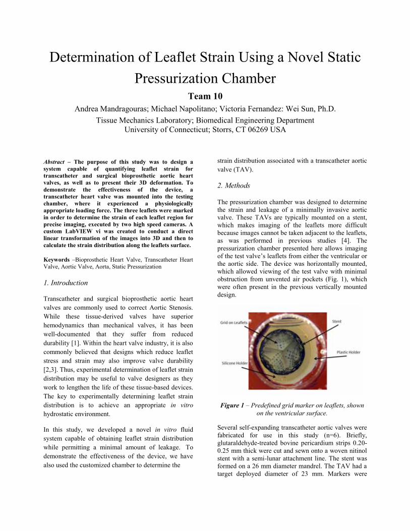
2. Methods The pressurization chamber was designed to determine the strain and leakage of a minimally invasive aortic valve. These TAVs are typically mounted on a stent, which makes imaging of the leaflets more difficult because images cannot be taken adjacent to the leaflets, as was performed in previous studies [4]. The pressurization chamber presented here allows imaging of the test valve’s leaflets from either the ventricular or the aortic side. The device was horizontally mounted, which allowed viewing of the test valve with minimal obstruction from unvented air pockets (Fig. 1), which were often present in the previous vertically mounted design.
Figure 1 – Predefined grid marker on leaflets, shown on the ventricular surface.
Several self-expanding transcatheter aortic valves were fabricated for use in this study (n=6). Briefly, glutaraldehyde-treated bovine pericardium strips 0.20-0.25 mm thick were cut and sewn onto a woven nitinol stent with a semi-lunar attachment line. The stent was formed on a 26 mm diameter mandrel. The TAV had a target deployed diameter of 23 mm. Markers were

placed on the surface of the three leaflets following a pre-defined grid (Fig. 1). The completed valve was then placed in a silicone holder to ensure that no leakage was permitted around the outside of the valve. This silicon holder was then mounted into the pressurized testing chamber.
A reserve tank was connected to the pressurized chamber to maintain test fluid in the chamber as it leaked through the valve. Another cylinder, filled with non-pressurized test fluid, was located downstream of the valve in order to maintain a constant fluid level, which allowed clear imaging of the valve’s leaflets (Fig 2.).
Figure 2 – Pressurization chamber with TAV mounted for strain distribution testing.
Testing was conducted by increasing transvalvular pressure from 40 mmHg to 200 mmHg with a step size of 40 mmHg. Transvalvular pressure was measured using two pressure sensors, which were placed upstream and downstream of the valve. Two Basler high-speed compact digital cameras were used to image the leaflets at each pressure. Images were simultaneously taken at specific pressures to determine the leaflet strain. The images were collected, and analyzed using a custom LabVIEW vi for each pressure. The strain was calculated using the deformation gradient of the markers at each step. The LabVIEW program was also used to reconstruct the linear transformation into a 3D image.
3. Results/Discussion
The device proved to be able to image the leaflets with little to no obstruction. The chamber maintained a consistent pressure during testing with minimal leakage. The results gathered from the experiment correlated with the previously simulated results, Li and Sun reported thin bovine pericardium leaflet strains of 12-18% [5]. The recorded data for strain at 120 mmHg in this device was measured at 13.2 ±2%. As the pressure increased, the leaflet strain also increased. This trend is shown in Figure 3, where the leaflet strain is graphed with respect to pressure. The transcatheter aortic valve, indicated by the blue, had a range of
pressure up to 200 mmHg and range of strain up to 17.6%. The bioprosthetic surgical valve, indicated by red, experienced a range of pressure up to 120 mmHg and a range of strain up to 8.1% [5]. It is believed that the surgical valve has lower strain due to its thicker leaflets (0.4 vs. 0.2 mm).
Figure 3 – Pressure vs. leaflet strain for transcatheter
and surgical bioprosthetic heart valves.
By determining leaflet strain in vitro, it may be possible to predict how the leaflets will perform in vivo. The analysis of the strain distribution may give insight into peak strain location or which designs reduce strain. These insights may be significant because higher strains are believed to correlate with leaflet damage and failure [2,3].
4. Conclusion
The experimental data collected in this study indicated that strain measurements can be reproduced in vitro. The device developed in this study will allow for future experiments to be conducted involving leaflet strain under varying conditions, and may benefit heart valve designers as they work to improve the durability of tissue-based devices by reducing peak stresses. 5. Acknowledgments Testing and device design were aided by Joe Calderan, Eric Sirois, and Caitlin Martin. Valve fabrication was performed by Rachel Adams, Michele Dalena and Amy Mitchell. Special thanks to Serge Doyon and Peter Glaude for assistance in machining. LabVIEW support and design provided by Dave Kaputa and Kewei Li. This study was supported in part by NIH HL108239. 6. References 1.Walley, V., et al.,1991, J of Thor and Cardio Surg, 102(2) 2.Schoen, F., et al., 1987,76(3), pp. 618-627. 3.Hilbert, S. L., et al., 1986,J Biomed Mat Research, 20,1411. 4.Sun W., et al., J Biomech Eng., 2005. 127(6) 5.Li, K, et al., Annals of Biomed Engr., 2010. 38(8)

Figure 1: Diagram of device components and interactions
Device to monitor and control the real-time pressures for the Intra-Articular Hydraulic Distension treatment of "Stiff Shoulder" Syndrome
Team 11
Vesko Zlatev,Kyle Bagshaw, Krystyna Gielo-Perczak, Ph.D. Department of Biomedical Engineering
University of Connecticut, Storrs, CT 06269, USA
Abstract—The purpose of this senior design project was to construct and test a novel device that will be able to measure the pressure within the shoulder joint capsule during the therapeutic procedure known as hydraulic distension. This involves the injection of a solution composed of saline, local anesthetics, and corticosteroids into a patient's shoulder joint in order to increase the diminished fluid volume and break up fibrous tissue formations. A porcine shoulder was then used as an animal model for testing of the various procedure optimizations and safety features implemented, including a negative-feedback control loop to regulate infusion rate based on the measured pressure.
Keywords-Intra-Articular Hydraulic Distension; Frozen/Stiff Shoulder; Adhesive Capsulitis; LabVIEW user interface; Negative-Feedback Loop Control
I. INTRODUCTION Adhesive Capsulitis, commonly referred to as "stiff" or "frozen" shoulder syndrome, is a chronic and debilitating condition that affects an individual's shoulder joint, namely the fibrous capsule responsible for connecting a person's upper arm bone (humerus) to their shoulder blade (scapula) and clavicle (collar bone). The capsule itself starts to become thicker and stiffer, which in turn reduces the volume of the capsule and the amount of lubricating fluid found within. This ultimately leads to not only chronic pain, but also severely limits how much a person is able to move their arm and shoulder. The most severe of cases will undergo extremely invasive surgery to remove fibrous tissue formations with the hopes of alleviating some of the symptoms, but even then the symptoms have been shown to return over time. A novel technique that has been gaining popularity as an alternative, minimally-invasive therapy for Adhesive Capsulitis is the Intra-Articular Hydraulic Distension of the shoulder capsule. This involves the use of a needle and syringe in order to gradually inject a saline solution of painkillers and corticosteroids into the shoulder capsule with the intention of physically distending (stretching out) the thickened and inflamed fibers of the capsule. The injected solution will then act to both increase the amount of lubricating fluid, as well as to provide pain relief and promote the healing of any damage. Since there are not currently any established standards on how the hydraulic distension procedure should be performed in regards to stiff shoulder syndrome, there is a great degree of variation in the administration of the procedure between
different physicians. Unfortunately, this practice has often led to the rupturing of the patient's shoulder capsule (a major setback in terms of recovery time) mainly due to the patient not being able to accurately gauge the pain felt during the procedure as a result of the painkillers used. Our purpose therefore became several-fold, namely to create a machine which could infuse the fluid at precisely controlled rates while simultaneously collecting data in real time about the pressures within the joint capsule. This would ensure that the shoulder capsule is optimally distended all while preventing its rupture by gradually decreasing the infusion speed based on the pressure data; create a way of communicating about different patients and procedures performed; and ultimately help establish some rules and guidelines for this novel procedure, as well as an alternative means of diagnosing and treating conditions or injuries of the shoulder in general.
II. DESIGN AND COMPONENTS The overall design of the hydraulic distension device has been broken down into four different "subsystems". These include the patient themself, the operator of the device, the fluid subsystem, and the computational subsystem. A diagram of the components and how they interact is shown in Fig. 1.
A. Patient Subsystem (green) Since the health and safety of the patient is our priority,
this sub-system includes everything related to that. The stability of the patient's arm throughout the procedure will
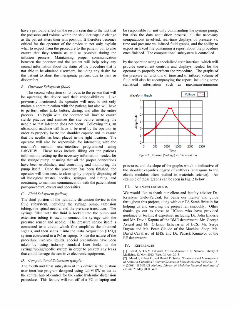
Figure 2: Pressure (Voltage) vs. Time test run
have a profound effect on the results seen due to the fact that the pressures and volume within the shoulder capsule change as the patient alters their arm position. It therefore becomes critical for the operator of the device to not only explain what to expect from the procedure to the patient, but to also ensure that they remain as still as possible during the infusion process. Maintaining proper communication between the operator and the patient will help relay any crucial information about the status of the procedure that is not able to be obtained elsewhere, including any desire for the patient to abort the therapeutic process due to pain or discomfort.
B. Operator Subsystem (blue) The second subsystem shifts focus to the person that will
be operating the device and their responsibilities. Like previously mentioned, the operator will need to not only maintain communication with the patient, but also will have to perform other tasks before, during, and after the entire process. To begin with, the operator will have to ensure sterile practice and sanitize the site before inserting the needle so that infection does not occur. Following this, an ultrasound machine will have to be used by the operator in order to properly locate the shoulder capsule and to ensure that the needle has been placed in the right location. The operator will also be responsible for interacting with the machine's custom user-interface programmed using LabVIEW. These tasks include filling out the patient's information, setting up the necessary information needed for the syringe pump, ensuring that all the proper connections have been established, and controlling and monitoring the pump itself. Once the procedure has been finished, the operator will then need to clean up by properly disposing of all biological wastes, needles, syringes, and tubing, and continuing to maintain communication with the patient about post-procedural events and necessities.
C. Fluid Subsystem (yellow) The third portion of the hydraulic distension device is the fluid subsystem, including the syringe pump, extension tubing, the spinal needle, and the pressure transducer. The syringe filled with the fluid is locked into the pump and extension tubing is used to connect the syringe with the pressure sensor and needle. The pressure sensor itself is connected to a circuit which first amplifies the obtained signals, and then sends it into the Data Acquisition (DAQ) system connected to a PC or laptop. Since the nature of the procedure involves liquids, special precautions have been taken by using industry standard Luer locks on the syringe/tubing/needle system in order to prevent any leaks that could damage the sensitive electronic equipment.
D. Computational Subsystem (purple) The fourth and final subsystem of this device is the custom user interface program designed using LabVIEW to act as the central hub of control for the entire hydraulic distension procedure. This feature will run off of a PC or laptop and
be responsible for not only commanding the syringe pump, but also the data acquisition process, all the necessary computations involved, real-time displays of pressure vs. time and pressure vs. infused fluid graphs, and the ability to export an Excel file containing a report about the procedure once finished. The computational subsystem is controlled by the operator using a specialized user interface, which will provide convenient controls and displays needed for the operator to properly perform the procedure. The graphs of the pressure as functions of time and of infused volume of fluid will also be accompanying the report, including some statistical information such as maximum/minimum
pressures, and the slope of the graphs which is indicative of the shoulder capsule's degree of stiffness (analagous to the elastic modulus often studied in materials science). An example of these graphs can be seen in Fig. 2 below.
III. ACKNOWLEDGMENTS We would like to thank our client and faculty advisor Dr. Krystyna Gielo-Perczak for being our mentor and guide throughout this project, along with our TA Sarah Brittain for helping us and ensuring the project ran smoothly. Other thanks go out to those at UConn who have provided guidance or technical expertise, including Dr. John Enderle and Mr. David Kaputa of the BME department; Mr. George Assard and Mr. Orlando Echevarria of ECS; Mr. Serge Doyon and Mr. Peter Glaude of the Machine Shop; Mr. David Cavallaro of EHS; and Dr. Patrick Kumavor of the EE department.
IV. REFERENCES [1]. Board, A.D.A.M. Editorial. Frozen Shoulder. U.S. National Library of Medicine, 12 Nov. 2012. Web. 08 Apr. 2013. [2]. Manske, Robert C., and Daniel Prohaska. "Diagnosis and Management of Adhesive Capsulitis." Current Reviews in Musculoskeletal Medicine 1.3-4 (2008): 180-89.US National Library of Medicine National Institutes of Health. 23 May 2008. Web.

Cervical Fusion Plate Derived from Cellulose Acetate Team 12
Casey McDermott, Andrew Carney, Kyle Ward, Krystyna Gielo-Perczak Ph.D, Dr. Sangamesh Kumbar Biomedical Engineering Department
University of Connecticut, Storrs, CT 06269 USA Abstract—The objective of this study was to design and manufacture a spinal fusion plate for the cervical vertebrae. The plate will be constructed out of cellulose acetate. Based on geometric constraints, the parameters of the design were optimized to enhance the mechanical strength of the plate. The plate was manufactured using a milling machine before being tested based on ASTM requirements.
I. INTRODUCTION Degenerative disc disease (DDD) is an illness that causes
the intervertebral discs in the spine to degenerate, possibly causing severe pain, along with other mechanical problems. It is one of the most prevalent diseases in the world, affecting about 80% of all people at some point in life. [1] In order to solve this, an intervertebral disc graft replaces the degenerated disc and fuses to the surrounding vertebrae. During the fusion process, the graft must be supported and held in place for the fusion to fully occur. Using screws that enter the vertebrae and hold them in place while fusion occurs, the graft is able to fuse to the vertebrae safely. A cervical plate is used to fixate the screws. Most research studies dealing with the spinal fusion plate and screws use a strong metal, such as titanium, to create the device. This is used mostly due to its strong mechanical strength, but problems arise such as the need for a second procedure to remove the plate, as well as immunogenicity issues. Our solution to this is to create a biodegradable plate and screws that degrades into biocompatible products that will do no harm to the body. In using a biodegradable plate, the mechanical properties of the plate are lower than when using titanium, along with having to consider other factors such as biodegradation rate and immunogenicity. We decided to use cellulose acetate mixed with hydroxyapatite, focusing our design on enhancing the mechanical properties of the fusion system. The design was created using a computer-aided design (CAD) program before being 3-D printed.
II. MATERIALS AND METHODS Within the design of the cervical plate system, the most necessary and important part of the project is the material being used. For this study, a combination of cellulose acetate and hydroxyapatite was used. The mixture contained 80 % by weight cellulose acetate and 20 % hydroxyapatite. This combination of materials enabled us to have biocompatible materials and biodegradation products that would cause no harm to the body. Along with this, the mixture was created to have a suitable degradation rate, as
the fusion process can take up to a year for completion. The design was created using the CAD programs ANSYS and SolidWorks. A basic model was created using the basic constraints that were placed on the geometry of the cervical plate, before running a 3-point bending simulation to test the equivalent Von Mises stress placed upon the plate. After this was done, the plate parameters were optimized in order to enhance the mechanical strength of the plate. Parameters that were optimized include things such as thickness, width, countersinks, as well as side- and end-cut length and depth. Optimizing all parameters and combining them allowed for the strongest possible plate that was possible. After the device was fully optimized and simulations were run based on using PLA properties within the CAD
Figure 1: FEA testing results of ANSYS model
program to ensure it would withstand the forces placed on it by the body, the file was exported and made to be compatible for 3-D printing. A Maker Bot 2 Replicator 3-D printer was used to create the cervical plate, using a PLA filament to create the device, using sequential layer by layer construction. After the plate was created, it was tested based on ASTM requirements. The plate was tested to failure, using tension, compression, torsion, and fatigue testing. This was then compared to the FEA testing within the CAD model to verify the results. Testing was done based on PLA material due to the inability to prototype the
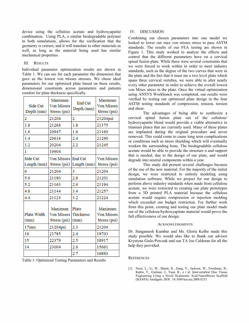
device using the cellulose acetate and hydroxyapatite combination. Using PLA, a similar biodegradable polymer in both simulations, allows for the verification that the geometry is correct, and it will translate to other materials as well, as long as the material being used has similar mechanical properties.
III. RESULTS Individual parameter optimization results are shown in Table 1. We can see for each parameter the dimension that gave us the lowest von misses stresses. We chose ideal parameters for our optimized plate based on these results, dimensional constraints across parameters and patients comfort for plate thickness specifically.
Table 1: Optimized Testing Parameters and Results
IV. DISCUSSION Combining our chosen parameters into one model we looked to lower our max von misses stress to pass ASTM standards. The results of our FEA testing are shown in Figure 1. This study worked to analyze the effects and control that the different parameters have on a cervical spinal fusion plate. While there were several constraints that we were forced to work within in order to meet industry standards, such as the degree of the two curves that were in the plate and the fact that it must me a two level plate which spans three cervical vertebra, we were able to alter nearly every other parameter in order to achieve the overall lowest von Mises stress in the plate. Once the virtual optimization using ANSYS Workbench was completed, our results were verified by testing our optimized plate design in the four ASTM testing standards of compression, tension, torsion and shear. The advantages of being able to synthesize a cervical spinal fusion plate out of the cellulose/ hydroxyapatite blend would provide a viable alternative to titanium plates that are currently used. Many of these plates are implanted during the original procedure and never removed. This could come to cause long term complications or conditions such as stress shielding which will eventually weaken the surrounding bone. The biodegradable cellulose acetate would be able to provide the structure n and support that is needed, due to the design of our plate, and would degrade into neutral components within a year. This study did present several challenges because of the use of the new material. For the majority of the initial design, we were restricted to entirely modeling using simulation software. While we project for our design to perform above industry standards when made from cellulose acetate, we were restricted to creating our plate prototypes from a 3D printed PLA material because the cellulose acetate would require compression or injection molding which exceeded our budget restriction. For further work from this point, creating and testing our plate model made out of the cellulose/hydroxyapitate material would prove the full effectiveness of our design.
ACKNOWLEDGMENTS
Dr. Sangamesh Kumbar and Ms. Gloria Kolbe made this study possible. We would also like to thank our advisor Krystyna Gielo-Perczak and our TA Joe Calderan for all the help they provided.
REFERENCES [1] Nesti, L., Li, W., Shanti, R., Jiang, Y., Jackson, W., Freedman, B.,
Kuklo, T., Giuliani, J., Tuan, R., e t al. Intervertabral Disc Tissue Engineering Using a Novel Hyaluronic Acid-Nanofibrous Scaffold (HANFS) Amalgam. DOI: 10.1089/ten.tea.2008.0215

Novel Polysaccharide-Derived Fixation Device for Anterior Cruciate Ligament (ACL) Reconstruction
Team 13 Derek Holyoak1, Alexander Werne1, Benjamin Roberts1, Gloria Kolb2, Sangamesh Kumbar3, Ph.D.
Krystyna Gielo-Perczak1, Ph.D. 1University of Connecticut Depatment of Biomedical Engineering, Storrs, CT 06269
2University of Connecticut Ventures 3University of Connecitcut Health Center Department of Orthopedic Surgery, 263 Farmington Avenue
Farmington, CT06030 Abstract—Ineffectiveness of current ACL reconstruction techniques suggests that a novel method for this surgery may be necessary. Devices currently being used are either too rigid or too flexible, resulting either in a stiffened tendon or tendon displacement, which ultimately causes pain and discomfort for the patient. The goal of this project was to design a fixation device that can be used for ACL reconstruction and to integrate a novel biodegradable, biocompatible, polysaccharide-derived material. The device was designed taking into consideration specific constraints due to the geometry of the knee joint, the loading of the ACL, and ease of use for the surgeon. Using CAD and FEA, a fixation device with a novel geometry, called the tendon casing, was created for the femoral side of the tendon, and an interference screw was designed for the tibial side. Under 2000N of loading (maximum tension in a native ACL [1]) and 10Nm of torque, the tendon casing experienced a maximum stress of approximately 33.4 MPa, while the tensile yield strength of the polysaccharide-derived material is, on average, 32.6MPa. These results show that the tendon casing does not rupture until a native ACL would, implying that it is sufficient for the ACL application. Thus, both the tendon casing and interference screw were 3D printed out of PLA. Future work includes fabricating a mold for the interference screw, so mass production can ensue, as well as physical testing of the device.
I. INTRODUCTION The anterior cruciate ligament (ACL) is a common site of
injury for people who lead active lifestyles (~200,000 injures per year in the United States) [2]. The ACL is one the most important ligaments in the knee and is necessary for stability and performing normal leg motions. To date, there is not a fully effective way to repair an ACL after it has been injured. There have been many successful surgeries performed to reconstruct the ACL, but the consistency of full recovery is still an issue. Oftentimes, patients of ACL reconstruction will need more than one surgery, infections may occur due to harmful byproducts, or the graft tendon will become too loose due to constant friction or too rigid because of lack of flexibility [3]. Clearly, there is need for an alternative method to fix these issues. In this project, it is proposed, by using a novel polysaccharide-derived material and a unique fixation device, the process of ACL reconstruction can be improved. This material has been proven to be completely
biocompatible, as well as biodegradable, which takes care of the problem related to harmful byproducts if the material is inside the human body for too long of a period. However, the mechanical integrity of the material does not match up with the strengths of materials currently being used for this application. Because of this, extensive biomechanical analysis was necessary in creating the proposed device. Computed Aided Design (CAD) and Finite Element Analysis (FEA) were the two primary techniques used to complete this project.
II. COMPONENTS The project called for two main components: one device
to fixate the graft tendon on the femoral side of the knee, and the other to fixate the tendon on the tibial side of the knee. The main factors in determining the geometries of these components were the physical makeup of the knee joint, the loading of native ACLs, ease of use for the surgeon, and the client’s needs. The client’s main desire was to fabricate an interference screw made out of novel polysaccharide-derived material. Therefore, it was decided that the interference screw would be used for the tibial side of our fixation device. Thus, the component designed to fix the femoral side would need to incorporate both the rigidity and flexibility that is necessary in creating a fixation device for ACL reconstruction. This component will be referred to as the tendon casing.
A. Interference Screw The first component of the design project is the
interference screw, as shown in the left image of Figure 1. This device is commonly used for ACL reconstruction, because of its simplicity in regards to both fabrication and ergonomic capabilities. The screw will be used to fixate the graft tendon on the tibial side of the knee.
Figure 1: Interference Screw and Mold

The ultimate goal for the interference screw was to create
a molding tool, so that the screw can be mass produced from the novel material. The mold is shown in the right of Figure 1. Much consideration went into designing the mold because of the possibility of producing undercuts in the screw threads and ensuring that the material could be injected into the mold with ease. Ultimately, the mold will be fabricated from a metal, most likely steel, so that heat compression molding can be used to produce the interference screws.
B. Tendon Casing The second component of the fixation device is the
tendon casing, as shown in Figure 2. This component will be surgically input in the same way as an interference screw, but it will function very differently. While the interference screw holds the graft tendon in place with its threads, the tendon casing contains a tunnel through which the graft tendon (harvested from the hamstring tendon) will be pulled. The reason behind this design was to allow for the use of a hamstring tendon rather than a patellar tendon, since the patellar tendon is harvested with bone blocks, causing weakness in the graft. Another reason was to allow for more flexibility than an interference screw. Lastly, the thread locking mechanism will prevent any undesirable translation of the tendon casing within the graft tunnel.
Figure 2. Tendon Casing
III. RESULTS Finite element analysis was the primary technique used
to assess the performance of the device. The primary focus of testing was the tendon casing, because of its completely novel geometry. The mechanical testing of the interference screw was not quite as important, because they are currently being used for ACL reconstruction surgery and have been proven to be mechanically sound. The most important testing of the screw will occur when the screw has been fabricated from the polysaccharide-derived material using heat compression molding.
For the tendon casing, however, there were a lot of design parameters that needed to be changed until the device could withstand the ultimate load of a native ACL, which is approximately 2000N [1]. No devices currently being used in today’s market can withstand such a load, so that was the goal. Our final FEA tests involved using a “mock” tendon, in the tendon tunnel, which can be seen in the right-hand part
of Figure 2. A moment of 10Nm and a force of 1000N were applied to either end of the mock tendon, resulting in a net force of 2000N, which represents worst case scenario. The setup of the simulation is shown in the left of Figure 3, and results are shown to the right of Figure 3.
Figure 3. FEA with 2000N force applied to mock tendon The results show that the tendon casing experienced a
maximum stress of approximately 33.4 MPa, which is almost equivalent to the material’s yield strength of 32.6MPa.
IV. DISCUSSION AND CONCLUSION This new fixation device takes into account the features
of devices currently being used for ACL reconstruction surgery and combines them to form a unique design with many positive aspects. The rigidity of the interference screw is incorporated into the tendon casing by applying threads to its outer surface. The flexibility of other devices is also incorporated by providing the tendon a tunnel to loop into, preventing threads from weakening the tendon and allowing the graft tendon to stretch freely. Furthermore, biocompatibility issues have been resolved because of the novel polysaccharide-derived material being used to fabricate the device. With all of these positive aspects, the tendon casing should be an excellent complement to the interference screw in providing both support and the necessary flexibility that the hamstring graft tendon needs to develop in order to become strong enough to replace a native ACL. Future work for this project includes fabrication of both the interference screw and the tendon casing from the novel polysaccharide-derived material. This entails using the molding tool and heat compression molding techniques. Lastly, the components of the device will be physically assessed for tensile, compression, and torsional properties.
REFERENCES [1] Scheffler, Sven U., C.M., Norbort P. Su¨dkamp, MD, Andreas
Go¨ckenjan, MD, Reinhard FG Hoffmann, MD, and Andreas Weiler, MD. "Biomechanical Comparison of Hamstring and Patellar Tendon." Arthroscopy: The Journal of Arthroscopic and Related Surgery 18.3 (2001): 304-15.
[2] Cooper, James A., Janmeet S. Sahota, W. Jay Gorum, Janell Carter, Stephen B. Doty, and Cato T. Laurencin. "Biomimetic Tissue-engineered Anterior Cruciate Ligament Replacement." Proceedings of the National Academy of Sciences of the United States of America 104.9 (2007): n. pag. Web. 3 Apr. 2013.
[3] Allen, Christina R., MD, J. Robert Giffen, MD, and Christopher D. Harner, MD. "Revision Anterior Cruciate Ligament Reconstruction." Orthopedic Clinics of North America 34 (2003): 79-98.
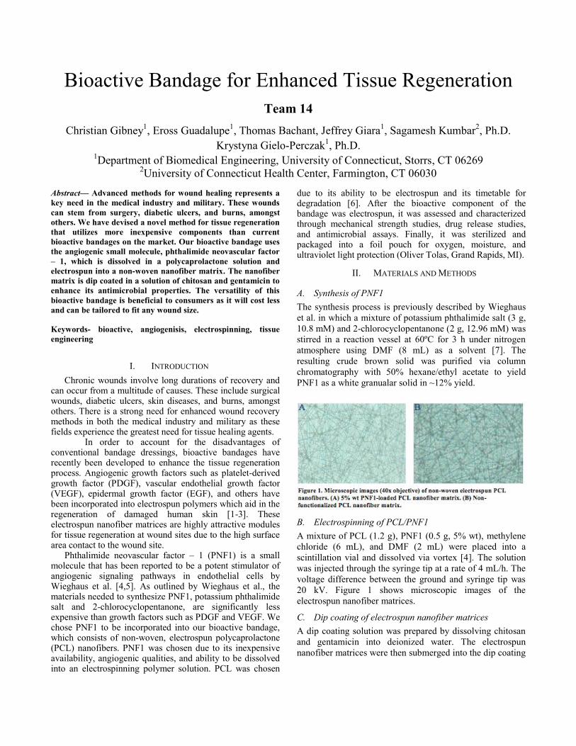
Bioactive Bandage for Enhanced Tissue Regeneration Team 14
Christian Gibney1, Eross Guadalupe1, Thomas Bachant, Jeffrey Giara1, Sagamesh Kumbar2, Ph.D. Krystyna Gielo-Perczak1, Ph.D.
1Department of Biomedical Engineering, University of Connecticut, Storrs, CT 06269 2University of Connecticut Health Center, Farmington, CT 06030
Abstract— Advanced methods for wound healing represents a key need in the medical industry and military. These wounds can stem from surgery, diabetic ulcers, and burns, amongst others. We have devised a novel method for tissue regeneration that utilizes more inexpensive components than current bioactive bandages on the market. Our bioactive bandage uses the angiogenic small molecule, phthalimide neovascular factor – 1, which is dissolved in a polycaprolactone solution and electrospun into a non-woven nanofiber matrix. The nanofiber matrix is dip coated in a solution of chitosan and gentamicin to enhance its antimicrobial properties. The versatility of this bioactive bandage is beneficial to consumers as it will cost less and can be tailored to fit any wound size.
Keywords- bioactive, angiogenisis, electrospinning, tissue engineering
I. INTRODUCTION Chronic wounds involve long durations of recovery and
can occur from a multitude of causes. These include surgical wounds, diabetic ulcers, skin diseases, and burns, amongst others. There is a strong need for enhanced wound recovery methods in both the medical industry and military as these fields experience the greatest need for tissue healing agents.
In order to account for the disadvantages of conventional bandage dressings, bioactive bandages have recently been developed to enhance the tissue regeneration process. Angiogenic growth factors such as platelet-derived growth factor (PDGF), vascular endothelial growth factor (VEGF), epidermal growth factor (EGF), and others have been incorporated into electrospun polymers which aid in the regeneration of damaged human skin [1-3]. These electrospun nanofiber matrices are highly attractive modules for tissue regeneration at wound sites due to the high surface area contact to the wound site.
Phthalimide neovascular factor – 1 (PNF1) is a small molecule that has been reported to be a potent stimulator of angiogenic signaling pathways in endothelial cells by Wieghaus et al. [4,5]. As outlined by Wieghaus et al., the materials needed to synthesize PNF1, potassium phthalimide salt and 2-chlorocyclopentanone, are significantly less expensive than growth factors such as PDGF and VEGF. We chose PNF1 to be incorporated into our bioactive bandage, which consists of non-woven, electrospun polycaprolactone (PCL) nanofibers. PNF1 was chosen due to its inexpensive availability, angiogenic qualities, and ability to be dissolved into an electrospinning polymer solution. PCL was chosen
due to its ability to be electrospun and its timetable for degradation [6]. After the bioactive component of the bandage was electrospun, it was assessed and characterized through mechanical strength studies, drug release studies, and antimicrobial assays. Finally, it was sterilized and packaged into a foil pouch for oxygen, moisture, and ultraviolet light protection (Oliver Tolas, Grand Rapids, MI).
II. MATERIALS AND METHODS
A. Synthesis of PNF1 The synthesis process is previously described by Wieghaus et al. in which a mixture of potassium phthalimide salt (3 g, 10.8 mM) and 2-chlorocyclopentanone (2 g, 12.96 mM) was stirred in a reaction vessel at 60ºC for 3 h under nitrogen atmosphere using DMF (8 mL) as a solvent [7]. The resulting crude brown solid was purified via column chromatography with 50% hexane/ethyl acetate to yield PNF1 as a white granualar solid in ~12% yield.
B. Electrospinning of PCL/PNF1 A mixture of PCL (1.2 g), PNF1 (0.5 g, 5% wt), methylene chloride (6 mL), and DMF (2 mL) were placed into a scintillation vial and dissolved via vortex [4]. The solution was injected through the syringe tip at a rate of 4 mL/h. The voltage difference between the ground and syringe tip was 20 kV. Figure 1 shows microscopic images of the electrospun nanofiber matrices.
C. Dip coating of electrospun nanofiber matrices A dip coating solution was prepared by dissolving chitosan and gentamicin into deionized water. The electrospun nanofiber matrices were then submerged into the dip coating

solution for 1 min at a time and removed to reveal the polymer coating.
D. Strength analysis of mechanical stability Tensile and ball burst testing was performed on strips of
the PCL nanofiber matrices in order to determine mechanical properties. The strips were loaded into tensile clamps of a Tinius Universal Testing Machine and elongated until breakage. Elongation at failure and ultimate force were recorded.
E. Quantification of PNF-1 release from PCL/Chitosan matrices
P-nitroaniline (PNA) was used as a substitute small molecule to estimate the release rate of PNF-1 from chitosan dip-coated PCL nanofiber mats. Specifically, 5% PNA was loaded in PCL mats and electrospun as mentioned in methods above. Over 2 weeks, the absorbance of PNA was quantified on a spectrophotometer at 400 nm from which the concentration release could be calculated.
F. Quantification of antimicrobial properties Dip coated PCL nanofiber matrices were tested in dynamic and static assays for antimicrobial potency. Staphylococcus aureus was chosen for agar plate culturing, as it is a bacterium that is commonly found on skin. Tests to decipher the zone of inhibition of varying gentamicin concentrations were performed in order to determine optimal dip coating conditions.
G. Sterilization and packaging The nanofiber matrices were sterilized via ethanol sterilization. The nanofiber matrices were then vacuum – sealed into foil pouches provided by Oliver Tolas. Figure 2 depicts the final packaged prototype of the overall bandage design.
III. DISCUSSION The electrospun PCL nanofiber matrices were
characterized through various studies and assays to compare the mechanical stability of the nanofiber matrices. After
successful incorporation of the PNF1 into the PCL nanofiber matrix, we conducted drug release studies using PNA, which exhibits similar kinetics due to its comparable molecular weight. In summary, these validation studies show our bioactive bandage’s viability for enhanced tissue regeneration and that PNF1 can be a vital player in the market for wound healing and tissue regeneration.
IV. CONCLUSION We report the ability to deliver the angiogenic small
molecule, PNF1, from non-woven electrospun PCL nanofiber matrices for enhanced tissue regeneration. By incorporating a dip coat of chitosan and gentamicin, we also have provided antimicrobial properties and reinforced mechanical strength to the bioactive component, which will aid in tissue recovery.
ACKNOWLEDGMENTS We would like to express our deepest gratitude to Dr.
Sangamesh Kumbar of the University of Connecticut Health Center along with his post-doctorate and graduate students for providing us with the laboratory workspace and guidance to carry out our project. We would like to thank Dr. Krystyna Gielo-Perczak for advising us through the project. We also thank Dr. Stewart Richardson for his assistance in column chromatography and NMR spectroscopy. We also give thanks to Dr. Amy Howell, Dr. Joerg Graf, Dr. Gino Intrieri, Dr. Roshan James, Deborah Hanna, and Sarah Brittain for their gracious assistance to our project.
REFERENCES [1] Barrientos, S., Stojadinovic, O., Golinko M. S., Brem,
H., Tomic-Canic, M. Perspective Article: Growth factors and cytokines in wound healing. Wound Repair and Regeneration 2008;16:585601.
[2] Choi, J.S., Leong, K.W., Yoo, H.S. In vivo wound healing of diabetic ulcers using electrospun nanofibers immobilied with human epidermal growth factor (EGF). Biomaterials 2008;29:587-596.
[3] Sahoo, S., Ang, L.T., Goh, J.C., Toh, S. Growth factor delivery through electrospun nanofibers in scaffolds for tissue engineering applications. J Biomed Mater Res A 2010;93A:1539-1550.
[4] Wieghaus, K.A., Nickerson, M.M., Aronin, C.E.P., Sefcik, L.S., Price, R.J., Paige, M.A., Brown, M.L., Botchwey, E.A. Expansion of microvascular networks in vivo by phthalimide neovascular factor 1 (PNF1). Biomaterials 2008;29:4698-4708.
[5] Wieghaus, K.A., Gianchandani, E.P., Neal, R.A., Paige, M.A., Brown, M.L., Papin, J.A., Botchwey, E.A. Phthalimide neovascular factor 1 (PNF1) modulates MT1-MMP activity in human microvascular endothelial cells. Biotechnology and bioengineering 2009;103:796-807.
[6] Lam, C.X.F., Hutmacher, D.W., Schantz, J.T., Woodruff, M.A., Teoh, S.W. Evaluation of polycaprolactone scaffold degradation for 6 months in vitro and in vivo. J Biomed Mater Res A 2008;90A:906-919.
[7] Wieghaus, K.A., Capitosti, S.M., Anderson, C.R., Blackman, B.R., Price, R.J., Brown, M.L., Botchwey, E.A. Small molecule inducers of angiogenesis for tissue engineering. Tissue Engineering 2006;12:1903-
Figure 2. The vacuum-sealed foil pouch containing the bioactive component of the bandage design with labeling.

Continuous Bowel Sound Monitoring System and Disposable Expiratory Pressure Manometer Connector
Team 16 Maren Wennberg1, James Coulson1, Nadjat Adoyi1, Leonard Eisenfeld, Ph.D.2, Rogers Pylant3, and
Nicole Silva3, John Enderle, Ph.D.1
1 University of Connecticut, Biomedical Engineering, Storrs, CT 06269 2 Connecticut Children's Medical Center, 282 Washington St, Hartford, CT 06106
3 Hartford Hospital, 80 Seymour St, Hartford, CT 06102
Continuous Bowel Monitoring Abstract— The first project involved the development of an electronic continuous monitoring system that allowed physicians to objectively assess bowel function in premature infants in the neonatal intensive care unit. A numerical value of the bowel sound will allow the physician to determine if the trend in bowel sounds is hypoactive (too slow) or hyperactive (too fast). The purpose of this project was to continuously acquire and record bowel sounds, graphically display the waveform, and calculate the frequency of the signal. This device will aid in the research of quantifying bowel sounds to ultimately create a product that counts the number of bowel sounds per minute.
Keywords- stethoscope, bowel sounds, infants
Disposable Pressure Manometer Connector Abstract—The second project involved the development of a disposable expiratory pressure manometer, which will aid respiratory therapists and speech therapists in the assessment of patients with tracheostomies to determine if they are candidates for a speaking valve. The device created is an inexpensive disposable expiratory pressure manometer to measure the pressure expelled by patients with tracheostomies when using a speaking valve. This device will replace current pressure manometers which are carried from bedside to bedside and are large, heavy, and must be cleaned between patients.
Keywords- tracheostomy, pressure manometer
I. INTRODUCTION A. Continuous Bowel Monitoring
The development of a continuous monitoring system to display the changes in bowel patterns will alert physicians earlier to help prevent a fatal bowel perforation for infants in the neonatal intensive care unit. One serious condition that develops in premature infants is called necrotizing enterocolitis (NEC) which leads to death of the small or large bowel wall due to a bacterial infection. Developing a display system will allow a physician to glance at the monitors to review all of the major systems including respiration rate, heart rate, and bowel sound frequency and amplitude. B. Disposable Pressure Manometer Connector
On a different note, the second project involved patients who have underwent a tracheostomy procedure. Patients
with a tracheostomy do not need to use their mouth or nose to breathe; instead they receive air directly into the trachea. A speaking valve can be placed for patients to enable them to speak with the tracheostomy. The speaking valve allows air into the lungs through the valve and tracheostomy tube in inspiration. When the patient exhales the valve prevents the air from exiting through the tracheostomy and diverts the air through the vocal cord and out of the mouth. An important assessment for patients to be allowed to use a speaking valve or cap is the expiratory pressure during use of a speaking valve. [3]
II. MATERIALS AND METHODS
A. Continuous Bowel Monitoring The most important design requirement was for the
system to be lightweight and small as to fit easily on a premature infant’s abdomen. Therefore, the team chose to create an electronic system using a lightweight accelerometer. This accelerometer weighs only 0.28 grams, requires a voltage of 3.0 Volts, and has a low current draw allowing the device to be powered by a battery. [1] The output of the accelerometer was connected to a National Instruments (NI) data acquisition (DAQ) system as an input to a LabVIEW program. B. Disposable Pressure Manometer Connector
A previous prototype was built using off-the shelf components to connect the tracheostomy tube, speaking valve, and an Ambu pressure manometer together. We replicated this device in SolidWorks and used a 3D printer to print the pressure manometer connector. The material used was 1.75 mm PLA filament, which is not approved for clinical use and therefore the connector must later be manufactured using a medical grade plastic.
III. RESULTS A. Continuous Bowel Monitoring
Throughout the experimentation, it was found that a high pass hardware filtering system, with a cutoff frequency of 80 Hz, was necessary to remove power line interference at 60 Hz as well as the DC offset. Mechanically, the best setup

was found using a metal lid with a diameter of 32 mm. The metal provided more amplification of sound than either using direct contact with the skin or a plastic diaphragm. The setup of the system is seen below in Figure 1.
Figure 1: Prototype
Bowel sounds are most frequently heard in the range of 200-500 Hz and therefore we decided to use LabVIEW to further filter the signal. [2] A bandpass filter was implemented with a lower cutoff frequency of 80 Hz and an upper cutoff frequency of 1500 Hz to ensure that all possible bowel sounds would be detected. The LabVIEW program is seen below in Figure 2 and is used to display the time signal, the fourier transform, and the root mean square of the signal. The number of bowel sounds are counted and displayed on the screen.
Figure 2: LabVIEW Front Panel
B. Disposable Pressure Manometer Connector The pressure manometer was printed using a 3D printer and had secure connections to the tracheostomy tube,
speaking valve, and Ambu pressure manometer.
Figure 3:Disposable Pressure Manometer Connector
IV. DISCUSSION A. Continuous Bowel Monitoring
The current design of this device is extremely useful to record bowel sounds and visualize the waveform and
frequency components of the signal. This device has extremely important applications to help ensure that an infant’s intestinal health is not overlooked in a neonatal intensive care unit. The software will need to be improved overtime before it is used as a clinical tool. B. Disposable Pressure Manometer Connector
The current design of the pressure manometer connector is successful; however the next step will be to design a manometer to replace the Ambu pressure manometer. Additionally, this device must be manufactured using a medical grade plastic.
V. CONCLUSION A. Continuous Bowel Monitoring
A continuous monitoring electronic stethoscope will be an objective aid to help physicians and nurses treating premature infants. Bowel sounds are an important indicator of many conditions and close monitoring can help prevent fatal conditions such as necrotizing enterocolitis from developing. Our device is made from an accelerometer attached to a metal lid to improve the mechanical amplification of the bowel sound. The NI DAQ is used to send a signal from the output of the accelerometer into a LabVIEW program where the signal is filtered and displayed graphically. This device could become a useful tool for physicians in the neonatal intensive care unit as well as in the monitoring of adult patients with possible bowel obstruction. B. Disposable Pressure Manometer Connector
The development of a disposable expiratory pressure manometer will aid the respiratory and speech therapists in determining a patient’s ability to speak. The current design of the connector is successful, however the next step will be to design a manometer to replace the Ambu pressure manometer. This connector is small in size and will be left on each patient’s bedside.
ACKNOWLEDGMENT We would like to thank Dr. Leonard Eisenfeld, Vineet Lamba, Rogers Pylant, Ms. Nicole Silva, Dr. Donald Peterson, Katelyn Burkhart, Takafumi Asaki, Newton de Faria, Eric Bernstein, Simon Kudernatsch, Tom Mealy, and Orlando Echevarria for their help with these projects.
REFERENCES [1] Knowles.com. N.p., n.d. Web. 6 Nov. 2012.
<http://www.knowles.com/ > [2] Ching, Siok Siong, and Yih Kai Tan. "Spectral Analysis of Bowel
Sounds in Intestinal Obstruction Using an Electronic Stethoscope." World Journal of Gastroenterology. Baishideng Publishing Group Co., Limited, 7 Sept. 2012. Web. 6 Nov. 2012. <http://www.ncbi.nlm.nih.gov/pmc/articles/PMC3435785/>
[3] Johnson, Douglas. "Tracheostomy Tube Manometry: Evaluation of Speaking Valves, Capping and Need for Downsizing." The Clinical Respiratory Journal (2009): 8-14. Web.
Speaking Valve
Ambu Manometer
Tracheostomy Tube
Speaking Valve
Sensor
of the system is seen below in Figure 1.
Sensor
Circuit
DAQ
Connector

Continuous Urinary Output Monitoring System Team 17
J. Etter1, A. Reichert1, U. Razzaq1, Leonard Eisenfeld, Ph.D.2, John Enderle, Ph.D.1
1University of Connecticut, Biomedical Engineering Department, Storrs, CT, USA 2Neonatal Care Unit at Manchester Memorial Hospital Manchester, CT, USA
Abstract: In order to effectively and efficiently measure the urinary output of a neonatal patient a “Catheterized Diaper” design is proposed. The system includes a funnel that is secured into the infant’s diaper and light suction to create an efficient seal and transport the urine. The urine is transported to a scale where the data is sent to a user interface program where the output is read in cc/kg/hr. The funnel was found to be successful in preventing the loss of any urine, and the suction carried the urine efficiently to the scale. The goal of the “Catheterized Diaper" is to provide health care professionals with a more efficient and safer way to monitor this specific aspect of the infant’s health.
I. INTRODUCTION The “Catheterized Diaper” was created as a device that uses a funneling system with the addition of suction to carry urine away from a patient to be weighed and monitored. Previously, health care providers had to weigh the diaper before and after a void to calculate the difference for output values. However, this was an extremely inaccurate and unsanitary method that increases the chance of bacteria throughout the NICU and decreases the health care providers ability to monitor the patients inner health. Also used was the catheter method, which increased the infant’s chance of contracting a Urinary Tract Infection, often making the situation worse. The idea behind the “Catheterized Diaper” is to provide the patient with optimal care, while ensuring that their inner health can be monitored efficiently by measuring their urine output levels.
II. MATERIALS AND METHODS A. Materials The funnel system that was implemented into the diaper was made from a silicon material; budget constraints prevented the silicon from being medical grade quality. The mold for the silicon was 3D printed out of PLA and ABS for the larger and smaller funnels respectively. The diapers are neonatal sizes donated from Manchester Memorial Hospital. The suction for the system comes from a Laerdal Compact Suction Unit 4 machine. The tubing is medical grade 3/15” tubing. The collection jar is a modified Dr. Browns baby bottle with a sealable lid. The scale used for weighing is an AND EK-1200i machine with a computer attachment cable. The programming used to convert weight data was LabVIEW. An anatomically correct doll is used for testing purposes of the completed system. B. Methods A funnel was designed on SolidWorks and 3D printed. After original testing on the larger size funnel was completed, the sizing was deemed incorrect according to the testing model and a smaller size funnel was created. The silicon was mixed at the proper ratio and poured into the funnel mold, to cure for about 6 hours. Once dry, a hole was placed at the bottom of the funnel for tubing to be secured via super glue. The tubing
was run through the diaper to the collection jar, where two holes were drilled into the bottle top to ensure an airtight seal. The data is then collected from the scale and put through a LabView program, where the final value is presented in cc/kg/hr.
C. Testing An anatomically correct doll was fitted with a tubing system to allow liquid to be excreted through the male genitalia. The doll was fitted with the correct size diaper and funnel system. The entire system was connected and it was found that the funnel successfully suctioned the “urine” away from the body to the scale without leakage.
III. RESULTS AND DISCUSSION The testing yielded positive results suggesting that the “Catheterized Diaper” could provide an efficient method for urinary monitoring. The urine was transferred with little left behind suggesting that there was little error with the transportation. The suction was kept between 50 mm Hg and 100 mm Hg which provided accuracy for the transportation of urine, but could possibly be too much suction for an infant. It was found that around 50 mm Hg was acceptable for neonatal infant’s, but it may still provide minimal irritation to the infant if place in vivo. In the future it might be beneficial to look at materials that provide a more sturdy structure for the funnel that would increase its ability to suction to the infant without the possibility of irritation from the suction unit. Figure 1 depicts the setup of the “Catheterized Diaper” in testing.
IV. CONCLUSION The proof of concept was proven due to the complete transport of urine from the testing subject to the collection jar. It was successfully weighed, with the data output sent through a conversion program to be shown on a user interface. It may be beneficial to look at the materials used, as the budget was a major constraint in choosing the materials that may have hindered some of the success of the project. Overall the “Catheterized Diaper” provides a good foundation for future ground work to be made in the field of urinary monitoring as it is essential in infant wellness.

Endotracheal and Oral Gastric Tube Fixation Devices Team 17
J. Etter1, A. Reichert1, U. Razzaq1, Leonard Eisenfeld, Ph.D.2, John Enderle, Ph.D.1
Abstract: The goal of this project was to design a method to fixate the endotracheal tube and oral gastric tube to an infant’s face while decreasing irritation, increasing the efficiency of oxygen and nutrient delivery, and decreasing the potential for additional injury. The Endotracheal intubation occurs through the center of the oral cavity, the “Upper Lip Clip” sits at the center of an infant’s upper lip with a track for the placement of the tube. The Oral Gastric Tube is flexible in terms of placement, so the “Clothespin Clip” sits on the side of an infant’s mouth.
I. INTRODUCTION Currently infants are intubated via the nasal cavity or via
the oral cavity with multiple adhesives attached, causing extreme irritation and airway blockage. The development of a new product is necessary to provide stability and efficiency to the process. The “Upper Lip Clip” provides a sturdy fixation point for the tube at the top of the mouth with minimal invasiveness to irritate the infant during endotracheal intubation. The clip sits on the upper lip, allowing for mobility and the correct angle for intubation. The “Clothespin Clip” sits on the side of the infant’s mouth with an access point for the tube to be inserted into the clip in a quick and effortless process during Oral Gastric intubation. Both clips were designed to be compact clips, providing accurate placement of the tubes according to anatomical geometry.
II. MATERIALS AND METHODS D. Materials
Clip design was done through SolidWorks software, to create a scaled drawing that represented the features of the clips. MakerBot 3D printer developed prototypes out of polylactic acid (PLA). Clips were dipped in Dragon Skin 10 Silicone of Medium Viscosity. Dimensional and pressure analysis was done on a silicone mold of an infant’s face. E. Methods
SolidWorks was used to create a realistic rendering of both the “Upper Lip Clip” and “Clothespin Clip” optimal designs. Both clips underwent extensive redesign in order to achieve the current designs. The clips are dimensioned according to anthropometry data, and account for the natural thickness of an infant’s cheek. The designs were altered throughout to include smooth and round edges to decrease the chance of irritation or harm. The silicone dipping increases adhesion to an infant’s cheek. A small hole will allow for the addition of a lease to prevent choking and an orthodontic rubber band will ensure the tubes correct placement. Once completed the clips were tested for dimensional accuracy and correct application of pressure. F. Testing
In order to ensure that the clips were of the correct dimensions and that the pressure exerted on the infant’s cheek was not excessive, a model of an infant’s face was
manufactured of silicone. The silicone was molded using clay and an infant doll head. The oral cavity was cut open to test how the clips would fit in vivo.
III. RESULTS AND DISCUSSION The clip shows the correct dimensions for an infant’s oral cavity. The pressure was more difficult to test, with testing limited by size. The error present may be in the material used. Originally a more flexible material was desired to comprise the clips, but this was prevented by limitations such as budget and time restrictions. Figure 2 and 3 demonstrate the “Upper Lip Clip” and the “Clothespin Clip” in testing.
IV. CONCLUSION The design of these clips would be first compact clips to efficiently fixate tubes when patients are being intubated. The devices were of the correct size and shape and were tested to ensure these characteristics. In the future it could be beneficial to look into ways to make the clips even more minimally invasive, with limited pressure on the patient’s cheeks. The “Clothespin Clip” and “Upper Lip Clip” were developed to become part of the framework in creating efficient and stable fixation devices for intubation.
ACKNOWLEDGEMENTS Team 17 would like to take this time to thank Dr. Eisenfeld for his vision regarding this project, and closely working with us. We would also like to thank Dr. Peterson and Joe Calderan for their feedback and help in developing a solution. The team would also like to thank the following for their help: Tom Mealy, Simon Kudernatch, Orlando, Peter, Serge, Dave Kaputa, Takafumi, Vineet Lambda, Erica Kramer, Dr. Rossler, Dr. Ansari, and Dr. Ryan.
REFERENCES [1] G. Schiffman M.D., “Endotracheal Intubation,”April 2007. [2] D. Klein M.D., “An Endotracheal Tube Fixation Device Constructed from Discarded Oxygen Tubing and Umbilical Tape,” Anesthesiology, Vol. 60, pp. 76, January 1984 [3] G. Schiffman M.D., “Endotracheal Intubation,”April 2007. [4] S. Roberts, A. Lucas, “Measurement of urinary coonstituents and output using disposable napkins,” Archives of Disease in Childhood, Vol. 60 pp. 1021-1024, January 1985

Pressure and Flow Rate Sensor for Controlled Delivery of Cell Media to Rat Lung Vasculature Ex-Vivo
Team 18 Alex Gray, Jeff Roberge, Dean Walston, Donald Peterson Ph.D
Biomedical Engineering Department University of Connecticut; Storrs CT, 06269, USA
Abstract – Lung disease is so prevalent that the client has asked us to create a pressure controlling device to accommodate their ex-vivo cell delivery system.
I. INTRODUCTION Lung disease is a leading cause of death among Americans and the leading cause of death among premature infants. Approximately 137,000 mortalities occurred in the United States in 2009 as a result of lung disease. The source of this disease can be traced to illness, social habit, or even genetic inheritance. Examples include asthma, allergies, chronic obstructive pulmonary disease (COPD), bronchitis, emphysema, cystic fibrosis, pneumonia, tuberculosis, edema, cancer, and interstitial lung disease (ILD). Patients with the above illnesses account for a large percentage of lung disease mortalities because they were unable to receive treatment. This introduces the fundamental issue at hand: availability of lung disease treatment is low.
II. RESEARCH Doctors and researchers in the Finck laboratory at the University of Connecticut Health Center have taken into account this issue regarding lung disease to conceptualize the idea of creating a transplantable human lung from the lung of another animal. The lab focuses on creating human lungs from rat lungs. To do this, the lungs from a pre-existing rat are removed and suspended in a bioreactor. Using chemical reagents and water, the rat cells within the lungs are lysed and washed away as to leave no trace of non-human DNA and histones. This process eliminates the chance of an autoimmune response when the lung is seeded with human unmbilical vein endothelial cells (HUVECs). The remaining structure following decellularization is known as the extracellular matrix (ECM), the protein-derived component of living tissue that provides physical support for cell attachment, encourages cell communication, controls cell proliferation and differentiation, and aids the healing process. When undifferentiated cells are seeded onto the ECM, then the ECM composition dictate how the HUVECs differentiate. As so, HUVECs from human newborns can be seeded onto a decellularized ECM scaffold to begin the development of a human lung for
transplantation. Fig. 1 below shows the vasculature of rat lung (dyed in methylene blue) in order to represent the cell seeding process.
Figure 1: rat lung vasculature dyed in methylene blue.
The organs would be cultured until given measures of lung functionality are achieved. These measures include perfusion of gases, ventilation, and standard total lung volume capacity. Successful results would confirm the creation of a biosynthetic lung scaffold that could be used in place of donor transplants for humans. Unfortunately, there are some aspects of this idea that have yet to be executed successfully, let alone be explored.
III. DESIGN Cell media delivery to lung vasculature needs to be controlled to promote optimal cell growth and adhesion. It is necessary to have multiple delivery programs built into the syringe pump to emulate the pressure and pulsatile nature of natural vasculature environments. Constant pressure delivery was the first program created to control the syringe pump. A pressure transducer connected to the end of the syringe pump using a three-way stopcock allows for the pressure to be monitored using a LabVIEW data acquisition device while the HUVECs are delivered to the lungs unimpeded, shown below in Fig. 2. The LabVIEW program takes a pressure value desired by the user and compares it to the measured pressure value. If the pressure is lower than the desired value, then the

program increases the dispensing speed of the syringe pump. If the pressure is higher than the desired value, then the program decreases the dispensing speed of the syringe pump; otherwise, the syringe pump will slightly oscillate around an optimal flow rate delivery that will deliver the media at a near constant pressure. Another important aspect of this program is the ability to pulsate the syringe pump
Figure 2: experimental set-up of the finished design.
dispensing speed. Using two flow rate values and two timers, the pump can deliver a pulsating flow at a desired speed and pattern. To add to the programming abilities, the user can type in a math function which will run the flow rate using the function's output. The user is able to deliver the cells in almost any flow rate pattern to find the optimal mechanical conditions for cellular growth. In addition, the readout on the front panel and through text file allows for easy retrieval and storage of data. This system greatly increases the efficiency of finding the proper cell delivery conditions so that biomimetic, transplantable lungs may become a reality in the future.
IV. RESULTS The human lungs are one of the last organs to fully develop during the nine months pregnancy. As a result, premature babies are at a greater risk of dying if not given a lung transplant. The client, Dr. Christine Finck, is currently researching methods of developing a solution to this problem at the University of Connecticut Health Center. Her research requires a pressure sensor for a syringe pump to determine to pressure in a lung scaffold. The goal of this design project was to create a system that would measure the pressure and flow rate within the media-filled
vasculature. Fig. 3 below is a sample of the first results obtained from this design.
Figure 3: LabVIEW front panel results obtained from testing.
The syringe pump responds to changes in pressure corresponding to the user input pressure value by either decreasing or increasing its dispensing speed. Future studies using this device will ascertain the optimal pressure for seeding the HUVECs to rat lung vasculature.
ACKNOWLEDGMENT
The design team would like to recognize the following persons for their assistance with this design: Todd Jensen, M.S., Erik Girard, M.D., Christine Finck, M.D., Donald Peterson Ph.D., Krystyna Gielo-Perczak Ph.D., Wei Sun, Ph.D., John Enderle, Ph.D., Takafumi Asaki Ph.D., David Kaputa, M.S., Sarah Brittain, B.S.E., Joseph Calderan, B.S.E., Jennifer Desrosiers, Orlando Echevarria, Nathan Murphy, B.S.E, and Peter Glaude. The team would also like to recognize and thank the University of Connecticut School of Engineering for financial support of this design.
REFERENCES
"Just Infustion Syringe Pump-Braintree Scientific." Just Infustion Syringe Pump-Braintree Scientific. N.p., n.d. Web. 27 Sept. 2012. <http://www.braintreesci.com/prodinfo.asp?number=BS-300>. Ott, H. C. et. al. Regeneration and orthotopic transplantation of a bioartificial lung. Nature Medicine, 16, 927-934 (2010). Ott, H.C. et al. Perfusion-decellularized matrix: using nature’s platform to engineer a bioartificial heart. Nat. Med. 14, 213–221 (2008). Suki, B., Ito, S., Stamenovic, D., Lutchen, K.R. & Ingenito, E.P. Biomechanics of the lung parenchyma: critical roles of collagen and mechanical forces. J. Appl. Physiol. 98, 1892–1899 (2005).

Creation of an in vitro Model to Test Emerging Wound Therapies for Human Wounds
Team 19 Nicholas Jannetty1, Adrienne King1, Stephen Miller1, Rajiv Chandawarkar, M.D.2, John Enderle, Ph.D.1
1University of Connecticut, Biomedical Engineering Department, Storrs, CT 06269 2University of Connecticut Health Center, Farmington, CT 06032
Abstract—Improvements are necessary for a current in vitro model of testing new therapeutic treatments for human wounds. The design offers a solution to extending the lifetime of the tissue culture by effectively oxygenating the media. For this testing, it is beneficial to prolong the life and health of the tissue sample in order to accurately and reliably mimic the wounding and healing properties of skin. In order to deliver oxygen to the media, non-permeable silicone tubing surrounds the inner perimeter of the Petri dish. Micro-sized holes puncture the tubing and oxygen is delivered from the tube to the media through these holes. The “bubbling effect” is insignificant enough that it will not disrupt the tissue sample. Creating quantifiable measurements that can compare wound healing was also achieved. A 3-D imaging system was constructed for correlation and size measurements. In addition, a simple Labview program was designed to compile biomarker data pH, glucose, and lactic acid.
Keywords-skin wound healing, oxygenation, 3D imaging, biomarkers
I INTRODUCTION The in vitro model involves four areas of interest;
tissue culturing the skin, wounding the skin, applying the therapies, and analyzing the healing process. This report focuses on two of these four areas.
A Oxygenation Static organotypic culturing is the method for growing
and maintaining healthy skin tissue samples without dynamic intervention. The skin samples include all layers of the skin (hypodermis, dermis, and epidermis). The sample is half submerged in DMEM media, to create long term culture at the air-liquid interface [1]. Additionally, the tissue lifespan can be further improved by increasing the amount of oxygen delivered to the tissue. Oxygen is a very important element in wound healing. There is limited availability of oxygen for the skin tissue samples due to its low solubility, slow diffusivity, and static state in culture media. Currently, methods are under investigation for oxygenation tissue cultures are bioreactors, formation of vasculature in vitro, and the use of oxygen carrier molecules [2].
B Quantifiable Analysis Current methods for measuring wound healing are
very simple and not particularly effective. Most hospitals will simply take an image of the wound with a ruler next
to it, which serves as a marker to measure the size of the wound. Images are then taken periodically and compared over time to view the progress of the wound. Currently, most methods for observing the progression of a wound over time are qualitative. Like the above example, they involve imaging and histology studies that provide little to no quantifiable data. There are a few methods in the trial stage that can provide some quantifiable data. Most of these rely on stereo vision, which is the same method that humans use to see depth. Using a two camera system, a computer can interpolate the distances between objects and the depth.
Various tests for biomarkers are used to objectively determine the extent and success of the wound healing process, such as proteases, protease inhibitors, and inflammatory markers. Lactic acid is known to stimulate endothelial growth and proliferation, which is crucial to the process of angiogenesis [3]. For these reasons, our experimental setup will monitor the levels of both these biomarkers. The measurements obtained will be compared over time and analyzed.
Furthermore, it has been found that maintaining an optimal pH level is crucial when it comes to cell or tissue culture. The pH level of the media is directly responsible for maintaining an appropriate ion balance, in addition to optimizing cellular enzymes’ functions and the capabilities for growth factors and hormones to bind to cell surface receptors [4].
C Objective This design project aims to extend this period so
that the wound healing process can be better analyzed for testing new therapeutic agents. Our design utilizes an oxygenation system to prolong the lifespan of the sample. Another goal is to develop quantifiable methods for measuring wound progression over time.
II MATERIALS AND METHODS
D Oxygenation Using Tubing A 50 mm radius polystyrene Petri dish is used to
culture the skin tissue samples. A Millipore organotypic culture stand is placed in the middle of the dish. Approximately 20 mL of DMEM media is poured into the Petri dish in order for the tissue to be half submerged. To oxygenate the media, an oxygen tank is hooked up to Tygon PVC tubing, which then delivers oxygen to the

media. The tubing dimensions are 1/16” ID and 1/8”OD. The tubing is connected to the tank by a McMaster Carr reducer. A hole is created on the lid of the Petri dish using a soldering iron. The hole is 1 cm from the center of the lid and is just over 1/8” in diameter. The Tygon PVC tubing is fed through the hole and wrapped around the inner circumference of the Petri dish. The tubing is anchored using four hex nuts. The hex nuts stay in place by magnets located on the outside bottom of the dish. At the end of the tubing is a McMaster Carr plug. Six inches of tubing is submerged in the media. Every ½” along the tubing, a micro-sized hole is punctured using a syringe needle. Less than 5 psi of oxygen is delivered from the oxygen tank, through the tubing, and bubbled into the media. The low pressure does not disrupt the tissue sample, yet still delivers increased amounts of oxygen.
E Imaging Setup Our set-up was made using a 3M Portable Projector, a
Logitech 9000 Webcam, and a plexiglass box. The camera and projector were mounted in the box at the correct angles to allow the computer to take the 3D image. The image is made using the David Laser Scan software, which takes advantage of structured light scanning. This method involves projecting lines of varying thicknesses onto the object of interest. The computer can then use these images to create a 3D rendering of the object.
F Compilation of Biomarker Data The biomarker analysis relies on the integration of
several computer programs. For the pH quantification, NI Vision Assistant allows the user to select a region of an image (in our case, the media) and it will convert the image to a pH level. The glucose program runs on java and relies on obtaining the recorded glucose information (via USB). Both the glucose and pH information can be exported into Microsoft Excel, however the user must manually input the lactic acid levels into an Excel file. From here, we will export all of this information from the multiple Excel files into NI LabVIEW, which will then be able to be conveniently outputted into a single Excel file.
III RESULTS AND DISCUSSION
G Oxygenation Using Tubing Delivering oxygen to the media will
consequently oxygenate tissue samples by mass transfer, which is the transport from an area of high concentration to an area of low concentration. Oxygen gas from the holes in the tubing dissolves into the media then migrates from the media to the tissue. After pumping a beaker of 350 mL water with oxygen at <5 psi for 5 min, the amount of oxygen in the water increased by >7 mg/L. After 20 min of oxygen delivery the oxygen tank was turned off. Even after 20 min, the dissolved oxygen content only decreased by 1 mg/L.
From this proof of principle, it stands to reason that if the pressure of oxygen delivered to the media is
constant, the amount of oxygen uptake of the cell will remain relatively the same. This system adequately delivers more oxygen to the tissue than a static culture, thereby supplying more nourishment.
H Biomarkers Cell and tissue cultures must be maintained in an
optimal pH level of the media in order to achieve the best results. For most cases, this optimal level is between 7.0-7.4 [4]. The Vision Assistant program is capable of determining the pH level of the media by analyzing the color from a user-defined area of a photograph. When the media is determined to be outside the optimal range, it signifies that a media change is needed. The glucose meter being used in this experiment is a typical meter that a diabetic patient might use. For testing purposes, the meter was used on various dilutions of apple juice. Measurements were able to be obtained for optimal glucose levels, in addition to extremes at both ends of the spectrum. These proofs of principle confirm that the user will be able to quantify the biomarkers present in the experimental setup and make alterations if needed.
IV CONCLUSION For our project we were able to create a method
for infusing oxygen into the tissue culture media. This will allow our client to significantly increase the amount of oxygen in the culture, hopefully allowing the tissue to survive longer. We also created a 3D imaging system that our client can use to monitor changes to the tissue over time. Additionally, we found 3 different markers for monitoring the tissue over time. By monitoring glucose, lactic acid, and pH levels in the media over time, our client will indirectly track the progress of the tissue over time. We feel that this will improve the overall method that our client uses to culture his tissue samples. Our client has suggested that the increased levels of oxygen will increase the lifespan of the tissue. Also the biomarkers and the imaging system will allow our client to better monitor the tissue.
Some further investigations would be to conclusively determine if an increase of oxygen will help the tissue remain alive in the long run. Additionally, the trends that the glucose and lactic acid display over time should be analyzed to determine correlations as the tissue thrives or dies.
REFEERENCES 1 Parenteau, Nancy L., Dr., Patrick Bilbo, Cynthia Nolte, Valerie S.
Mason, and Mireille Rosenberg. "The Organotypic Culture of Human Skin Keratinocytes and Fibroblasts to Achieve Form and Function." Cytotechnology 9.1-3 (1992): 163-71.
2 Blitterswijk, Clemens A. Van., and Peter Thomsen. "Chapter 12 Cell Nutrition." Tissue Engineering. London: Academic, 2008. N. pag. Print.
3 Falanga V. (2005). Wound Healing. American Academy of Dermatology (AAD).
4 Introduction to Cell Tissue and Culture. Mather, Jennie, and Penelope Roberts.N.p.:Springer,1998.Pri

Improvements to Endoscopic Devices to Aid Gastroenterologist by Increasing Ease and Efficiency of Procedures
Team 20 Linda Caporale1, Alex Gale1, Andy Xie1, John Birk, M.D.2, Donald Peterson, Ph.D.2
1University of Connecticut, Biomedical Engineering Department, Storrs, CT, USA 2University of Connecticut Health Center, Farmington, CT 06032
Abstract—This paper discusses two medical devices: an ERCP (endoscopic retrograde cholangiopancreatography) sphincterotome and an endoscopic bite block. The need for design changes in these two medical devices commonly used by gastroenterologists is addressed along with how these changes will enhance current procedures and impact the field of gastroenterology in a positive way. The changes made as well as prototype development and validation methods are outlined. The validation of the devices included a variety of procedures such as finite element analysis, physical compression testing, and pressure tape analysis.
I. Introduction The invention of the endoscope has led to vast
improvements in non-invasive and minimally invasive medical procedures. An endoscope is a long tube with several channels as well as a light and camera on the distal end. It is maneuverable and equipped with a port for the collection of visual data. They are typically around three feet long and possess one lumen for water or dye injection and the other, the working channel, for housing a variety of wire-like devices used in procedures. As a result of the development of the field of endoscopy, there are a multitude of procedures that can now be performed without the need for incision because physicians
are able to operate through pre-existing body openings .
Aside from being revolutionary medical devices, endoscopes are also very expensive pieces of equipment. They
are commonly inserted into the
mouth of a patient for upper gastrointestinal procedures. This presents issues because patients may bite down on the device. The human biting force is strong enough that it may permanently damage the scope which is priced at more than
$5,000. In order to alleviate this issue, the bite block, shown in Figure 1, was invented. It is a small medical device that is placed into the mouth of the patient and prevents them from damaging the scope during procedures.
An example of a device that is placed into the working channel of an endoscope and used to perform otherwise ineffective and nearly impossible surgeries is a sphincterotome, shown in Figure 2. A sphincterotome is the medical device most commonly used for ERCP and sphincterotomies. It is a long narrow device with a fine tipped end that can be used for the cannulation of the bile duct and the removal of bile stones. It has a handle at one end, and an exposed cutting wire at the other. A current can be applied to the cutting wire in order to make incisions within the biliary tree after the device is in place. The handle at the proximal end allows for the physician to flex the tip at the distal end while making incisions.
II. Current Product Drawbacks and Design Modifications The currently used bite blocks are designed with simplicity in mind. They are as basic as they can possibly be while still achieving their desired purpose. They are uncomfortable to patients as well as inconvenient to physicians. They are not always effective in holding open the mouth and they get in the way of assorted tubing such as oxygen delivery systems and CO2 detection devices. They often have to be cut or partially removed in order to accommodate other devices that are more important. Finally, none of the current models have any housing for the tongue. When they are placed into the mouth of a patient, the tongue can slip back into the throat and become a choking hazard.
Figure 1. Common bite block from Upper Gastrointestinal Endoscopic procedures [1].
Figure 2. Boston Scientific Hydratome [2].

The design changes that would lead to a vastly improved upper gastrointestinal bite block would include features that address all of these common drawbacks. The improved bite block design has accommodations for the tongue as well as assorted tubing. It is also proven effective in holding open the mouth. It is stronger than a tested market sample as well, indicating that it has sufficient strength and thickness to prevent the jaw from closing. The current sphincterotomes are a large improvement on the tools and procedures that were previously used for the same medical issues. However, because this practice was so much better than the previous, most physicians ignored how difficult it really was. Sphincterotomes are designed with rounded tips, which is a poor design for moving something into a potential space. The improved Sphincterotome tip design includes a tapered tip that is optimal for the location and cannulation of the papilla of vatar during sphincterotomies.
III. Validation Methods The improved endoscopic bite block was tested in a variety of ways. The first and most important of those tests was a finite element analysis test. This was conducted on the portion of the bite block that would come into contact with the teeth. The test was done to determine if the design could
withstand the force of human mastication. When a 250N force was applied to the bite block on a rectangular contact surface, it only deformed 0.2mm. When 294 PSI (2 MPa) of pressure was applied on a tooth shaped contact surface, the bite block displacement was less than one micrometer. In order to generate a greater comparison for this information, a currently used bite block made by US Endoscopy (Encompass) was physically compression tested in a Tinuis Olsen UTM. The Encompass bite block exhibited 7mm of deformation at a force of 247 N. Indicating that the improved design is stronger than an on the market product. The force vs. displacement graph for the compression can be seen in Figure 4. The bite block was also validated through pressure testing. Pressure tape was used to collect data. The maximum amount of force possible was applied to the bite block and the contact
area and total pressure were measured in three trials. The data can be seen in Figure 5. The values were used separately and in conjunction with the finite element analysis testing. The improved sphincterotome tip was modeled and inspected by a practicing gastroenterologist. It was also analyzed in the finite element analysis program, Ansys. The results showed that 1000N of force on a 0.5mm square contact surface generated significant damage to the tip that would render it no longer functional.
IV. Conclusion
There is much room for improvement in many of the current medical devices on the market. The improved bite block design and improved sphincterotome tip design are examples of simple design changes that can make drastic differences in efficiency and functionality. Through several different validation methods, the improved designs were proven better than the previous.
References [1] Gastroscopy single-use bite block [Online]. Available:
http://www.medicalexpo.com/prod/endomed-endoskopie-hygiene/gastroscopy-single-use-bite-blocks-68369-464582.html
[2] Hydratome RX Cannulating Sphincterotomes [Online]. Available: http://www.bostonscientific-international.com/Device.bsci? page=HCP_Overview&navRelId=1000.1003&method=DevDetailHCP&id=10031341&pageDisclaimer=Disclaimer.ProductPage,%20Disclaimer.ReservedForMedProfs
Acknowledgments We would like to acknowledge the contributions of Dr. Peterson, Dr. Gielo-Perczak, Takafumi Asaki, Sarah Brittain, Simon Kudernatsch, and Chris Foster.
Figures 3a & 3b. Compression analysis of the improved endoscopic bite block.
Figure 5. Maximum value biting pressure analysis study.
-40000
-30000
-20000
-10000
0
-30000 -20000 -10000 0
Dis
pla
cem
en
t
Force
Force vs Displacement of UTM Crushing Experiment
Figure 4. Trend of force vs. displacement for compression of comparable
product.

Ultrasound Mediated Non-Union Fracture Repair Device Team 21
Yvonne Nanakos1, Aimon Iftikhar1, Kelly Stratton1, Nicholas Calistri1, Yusuf Khan2,3, Ph.D. Krystyna Gielo-Perczak1, Ph.D.
1Department of Biomedical Engineering, University of Connecticut, Storrs, CT 2Department of Chemical, Materials & Biomolecular Engineering, Storrs, CT
3University of Connecticut Health Center, Farmington, CT 06030
Abstract— Tissue-engineered systems involve the use of cells, growth factors, and scaffolds to repair and restore tissue function. Ultrasound is used as a treatment for clinical fracture repair. Evaluating the mechanism behind the efficacy of low intensity pulsed ultrasound (LIPUS) for fracture repair has revealed that the existence of a small mechanical force that may be beneficial to repairing musculoskeletal tissues using tissue-engineered scaffolds. Using the elements of a collagen hydrogel scaffold synthesis, ultrasound, and principles of musculoskeletal tissue regeneration, a fracture repair device has been designed. The proposed device is a bone fracture repair system that works with a scaffold component as well as an ultrasound component. This device is designed to enhance current techniques of bone formation in a more efficient and a minimally invasive way. It will serve as an alternative solution to surgical methods of healing bone fractures, especially since the medical industry is shifting towards least invasive methods of treatment. This device will also serve as the answer to healing non-union fractures, or fractures that do not heal on their own for unknown reasons.
Keywords: Non-union fracture, LIPUS, Collagen hydrogel scaffold
I. INTRODUCTION In the field of biomaterials, researchers and clinicians
are constantly seeking to improve the efficiency and rate of healing of fracture repair. It has been shown for non-union fractures that all periosteal and endosteal repair processes will stop if there is no surgical intervention. Therefore, it is convenient to both the clinician and primarily the patient, to have a less invasive, alternative means for treatment. Delayed healing can lead to various complications such as infection, malformations of the healing site and a multitude of secondary defects.
The most common method of bone repair consists of resetting the joint or bone to a position of function, immobilizing it in place and simply waiting for the natural healing cycle to occur. Up to 10% of fractures can be categorized as delayed-union or nonunion, both of which require secondary intervention [1]. These interventions usually require the bone to be connected to itself using a plate and bone screws. In some cases, improperly applied
primary treatments result in nonfunctional healing processes such as hypertrophic non-unions.
This work with biomaterials has focused on orthopaedic devices and how they can be improved. Current research has shown that osteoblasts form mineralized bone tissue faster when subjected to Low-Intensity Ultrasound (LIPUS). The project focuses on designing a system that includes the necessary parts for a clinician to seed a tissue scaffold with osteoblasts and then inject it at the desired wound site. The system can then be activated with an ultrasound in a procedure that is minimally invasive.
II. DESIGN
A. Objective In order to develop a method to enhance bone growth at
fracture sites, several designs were proposed. From them, one optimal design was chosen and modified for the fracture repair system. This design not only encourages osteogenesis, but is also non-toxic and biocompatible. The optimal design chosen was that of a collagen hydrogel scaffold.
The hydrogel closely resembles the extracellular matrix of soft tissues. If implanted at a bone defect, the hydrogel will be too pliable to replace the physical functions of the missing bone. However, it is suitable for encapsulating osteoblasts and other cells needed for bone formation. In addition to this, the relatively low Young’s modulus allows for the necessary deformation when exposed to low-intensity ultrasound waves.
The osteoblast and collagen suspension is loaded into a syringe in the liquid state to be implanted directly into the wound or defect site via injection. After injection, the mixture forms a gel consistency as it reaches body temperature. The procedure is minimally invasive and easily performed with only an ultrasound imaging device to guide the surgeon. Single-use syringes and sterile manufacturing conditions for the hydrogel greatly reduce the chance of infection.
B. Device Characterization and Methods This scaffold was constructed with collagen, PBS,
NaOH, and a media solution. The constructed scaffold
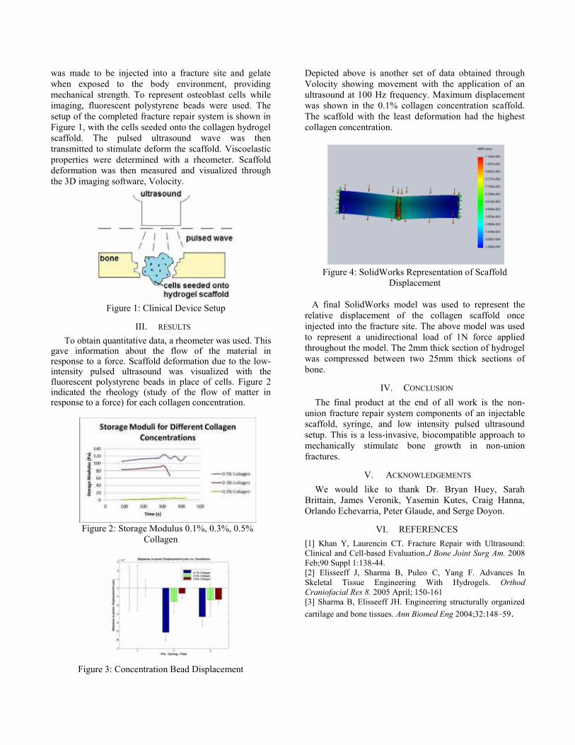
was made to be injected into a fracture site and gelate when exposed to the body environment, providing mechanical strength. To represent osteoblast cells while imaging, fluorescent polystyrene beads were used. The setup of the completed fracture repair system is shown in Figure 1, with the cells seeded onto the collagen hydrogel scaffold. The pulsed ultrasound wave was then transmitted to stimulate deform the scaffold. Viscoelastic properties were determined with a rheometer. Scaffold deformation was then measured and visualized through the 3D imaging software, Volocity.
Figure 1: Clinical Device Setup
III. RESULTS To obtain quantitative data, a rheometer was used. This
gave information about the flow of the material in response to a force. Scaffold deformation due to the low-intensity pulsed ultrasound was visualized with the fluorescent polystyrene beads in place of cells. Figure 2 indicated the rheology (study of the flow of matter in response to a force) for each collagen concentration.
Figure 2: Storage Modulus 0.1%, 0.3%, 0.5%
Collagen
Figure 3: Concentration Bead Displacement
Depicted above is another set of data obtained through Volocity showing movement with the application of an ultrasound at 100 Hz frequency. Maximum displacement was shown in the 0.1% collagen concentration scaffold. The scaffold with the least deformation had the highest collagen concentration.
Figure 4: SolidWorks Representation of Scaffold
Displacement
A final SolidWorks model was used to represent the relative displacement of the collagen scaffold once injected into the fracture site. The above model was used to represent a unidirectional load of 1N force applied throughout the model. The 2mm thick section of hydrogel was compressed between two 25mm thick sections of bone.
IV. CONCLUSION The final product at the end of all work is the non-
union fracture repair system components of an injectable scaffold, syringe, and low intensity pulsed ultrasound setup. This is a less-invasive, biocompatible approach to mechanically stimulate bone growth in non-union fractures.
V. ACKNOWLEDGEMENTS We would like to thank Dr. Bryan Huey, Sarah
Brittain, James Veronik, Yasemin Kutes, Craig Hanna, Orlando Echevarria, Peter Glaude, and Serge Doyon.
VI. REFERENCES [1] Khan Y, Laurencin CT. Fracture Repair with Ultrasound: Clinical and Cell-based Evaluation.J Bone Joint Surg Am. 2008 Feb;90 Suppl 1:138-44. [2] Elisseeff J, Sharma B, Puleo C, Yang F. Advances In Skeletal Tissue Engineering With Hydrogels. Orthod Craniofacial Res 8. 2005 April; 150-161 [3] Sharma B, Elisseeff JH. Engineering structurally organized cartilage and bone tissues. Ann Biomed Eng 2004;32:148–59.

Sensory Board for Adam’s Adventure Playground Team 22
Danielle Napoli, Alyssa Smith, Christine Wakefield Department of Biomedical Engineering
University of Connecticut, Storrs, CT 06269 USA
Abstract—Inspired by a 7-year-old boy blinded by bacterial meningitis, Adam's Adventure, located in Tolland, CT, is a playground for children of all abilities. This project consisted of building a sensory board for the Adam's Adventure in order to stimulate children's senses. Designed and built by a team of three biomedical engineering students, this sensory board is an interactive wall with games and activities integrated into it. This board is accessible to children who may be autistic, visually impaired, hearing impaired, or with mobility impairments, including use of a wheelchair. More importantly, this board allows these children to have fun, which is something they may find challenging at typical playgrounds. At 12 feet wide and up to 4.5 feet in height overall, this board includes six different panels, each with a different activity. These panels include motion sensors, music, a memory game, Braille riddles, and more. Additionally, this board has been designed to be sustainable and vandalism-proof. With a year’s worth of hard work and effort, this project has proved to be very rewarding, for a great purpose and a wonderful local community.
I. INTRODUCTION Playgrounds, which are typically a place for children to
relax and have fun, can be a challenge for children with special needs. Disorders such as autism, mobility impairments, deafness, blindness and many others can greatly affect a child's quality of life by limiting their ability to interact with other children and the world around them.
Adam’s Adventure, initially inspired by the story of Adam Mlodzinski, is a playground for special needs children of all ages. This typical 7-year-old boy contracted bacterial meningitis, which sent him into a coma for several months. After months of praying and hoping, he woke from the coma. Unfortunately the bacterial meningitis left him blind and with learning disabilities caused by brain damage from the disease. Despite being blind and having to relearn basic skills, Adam has been able to resume his childhood and continues to bring joy to those around him. This inspiring young man has made a difference in so many lives that several residents in the town of Tolland have dedicated many hours of their free time to build a playground in Adam’s name to make all children, regardless of any disabilities that they might have, feel welcome.
A sensory board can be described as a wall filled with interactive games. These games are all targeted toward children with disabilities. The six parts of this sensory board are a memory game, riddles with the answer in Braille, sensors which detect motion and subsequently light up LEDs, a wheel which turns a rod, a musical keyboard and chimes, and a game which allows children to create a
multi-colored picture out of lights. The board is also made so as to be accessible to all, including those confined to wheelchairs.
II. METHODS The sensory board was made out of ¾ inch thick high-
density polyethylene (HDPE), a typical playground material which is UV resistant, graffiti and scratch-resistant, moisture resistant, and will not crack or splinter. The middle section of the sensory board, which consists of the Braille riddles and the wheel panel, is 40.5 inches wide by 36 inches tall. All the side panels are 40.5 inches wide by 24 inches tall. From one side to the other, the total thickness of each section, with space in between for electronics, is 5 inches. Four posts hold each of the three sections together, and will allow the sensory board to be bolted into the ground (Fig. 1).
The memory game consists of six game buttons and a start button; these buttons have been modified to work properly and to be waterproof. The create-a-picture panel consists of a 9x9 grid of buttons, as well as a reset button and color buttons for red, green, and blue color changes. The motion detecting panel consists of four ultrasonic sensors each with six white LEDs around it. The music panel consists of chimes as well as buttons ordered to look like music notes; the notes have a free play setting as well as a way to learn to play a particular song.
For the create-a-picture, to ensure that the buttons fit properly, a support piece had to be made. Cubify’s Cube 3D Printer was used to adjust the size of square holes made by the machine to fit that of some pushbuttons. The material used by this printer is an ABS plastic, the material of which Lego’s are made.
III. RESULTS Each panel has been made successfully. The panels with
electrical components use Arduino microcontrollers, which will be supplied power from the concession stand at the
Figure 1. Organization of Sensory Board

playground once it is installed there. Pictures of the panels can be seen below.
IV. DISCUSSION One of our panels is the memory game, an activity in
which the children will have to memorize a pattern of lights and repeat it back to the board. This panel in particular was made to cater to children with autism.
The Braille panel includes the entire Braille and standard alphabets, and three riddles with the answers only in Braille. The goal of this panel was to cater to children who have visual impairments or may be blind, as well as to help others learn some Braille.
The sonar board contains four sonar sensors, each with connected to 6 LEDs. When a child walks in front of the board, or moves around, they will light up the surrounding LED’s. The purpose of this panel is to get children to move around, and since there is no requirement for fine motor skills, most children, even those with mobility impairments, can participate.
The wheel game has a wheel in the center of the panel and children will be able to spin the wheel and when it gets to a certain point, a noise will sound. The goal of this panel was to also get children to move around and allow
blind children to participate as well, since there is a noise aspect to it.
A music panel gives children the opportunity to play songs even if they don’t know how to read music. They will have the choice of either selecting a song and following along with the music, playing their own song, or playing with chimes. Since all the buttons on this panel light up, both blind and deaf children can play.
Finally, the create-a-picture panel allows children to be as creative as they would like. There is a 9x9 grid of buttons, and the child can select a color that they want the button to be, and whatever button they press will light up that color, so that they can essentially create their own picture.
V. CONCLUSION Overall, this is a very rewarding project, as it is for a
great cause within a local community. This project has truly been a challenge because it is so diverse. Sometimes the electronics are difficult, sometimes the assembly is tricky and other times it has been challenging to ensure that everything is waterproof. Despite the challenges, this sensory board, built to withstand any weather, has been a successful and meaningful learning experience.
ACKNOWLEDGMENTS Thank you to our sponsor, Brian Schwarz, our advisor,
Dr. John D. Enderle, and our teaching assistant, Sarah Brittain, for the guidance throughout this project.
Thank you to the UConn School of Engineering and the Biomedical Engineering Department for funding this project. Thanks to the following companies for donating to us or discounting their products: Miracle Recreation, MaxBotix, MyDoorSign, NKK Switches, and Sparkfun.
Thanks to the Adam’s Adventure Board and Megan Baker, special education teacher at Mansfield Middle School, for giving feedback in the design of our project.
Thanks to the following people who helped us with our project: Dave Kaputa, Sung-Yeul Park, Paul Dufilie, John Chandy, Kevin McLaughlin, Sonya Renfro, Jennifer Desrosiers, Peter Glaude, and Serge Doyon.
REFERENCES [1] Adams Adventure. N.p., n.d. Web. 23 Apr. 2013. <http://www.adamsadventure.org/>. [2] "Playground Equipment for Commercial Use." Miracle Recreation. N.p., n.d. Web. 23 Apr. 2013. <http://www.miracle-recreation.com/>. [3] "The Web's Largest Source for Door Signs." My Door Signs. N.p., n.d. Web. 23 Apr. 2013. <http://www.mydoorsign.com/>. [4] "Ultrasonic Sensors, High Performance Distance & Proximity Sensors." MaxBotix. N.p., n.d. Web. 23 Apr. 2013. <http://www.maxbotix.com/>. [5] NKK Switches. N.p., n.d. Web. 23 Apr. 2013. <http://www.nkkswitches.com/>. [6] SparkFun Electronics. N.p., n.d. Web. 23 Apr. 2013. <https://www.sparkfun.com/>. [7] Arduino. N.p., n.d. Web. 23 Apr. 2013. <http://www.arduino.cc/>.
C
Figure 2. A) The Braille riddles, (B) the wheel game panel, (C) the music panel, and (D) the sonar panel. The empty box in the (C) is for the chimes. Not pictured: the memory game and create-a-picture.
A B
C
D
A B

Robotic Rehabilitation and Targeted Muscle Training Device Team 23
Brian C. Coleman, Eric B. Sands, James R. Valliere, Donald Peterson Ph.D Biomedical Engineering Department
University of Connecticut, Storrs, CT 06269, USA
Abstract—A robotic rehabilitation device has been designed to aid in therapy for individuals with post-stroke hemiparesis and other upper limb motor deficiencies. It was also designed to provide targeted muscle activation training to patients seeking to prevent muscular atrophy in zero-gravity environments. The device was redesigned from a first generation device to a newer model that is lighter, safer, more efficient, and overall simpler to use. Additionally, it can record the patient’s progress over multiple therapy sessions and provide relevant information to the attending therapist in an effective manner. The device is a departure away from the traditional methods of physical therapy by offering high fidelity in repetition and precise control in redeveloping a patient’s neuromuscular system in the affected region while retaining and rebuilding muscle mass through use. The proposed device advances away from the current commercial machines by offering higher portability for a robotic rehabilitation device. With robotics being the clear future for rehabilitation and potentially muscle training, this device will increase patient quality of life for post-stroke hemiparetics, patients with localized elbow injury, and patients trying to maintain or increase muscle mass.
Keywords-robotic; rehabilitation; muscle; atrophy
I. INTRODUCTION The future of rehabilitation and physical therapy
inevitably integrates with the developing technologies in the field of robotics. Through repetitive balance and coordination exercises, the goal of typical rehabilitation techniques is to retrain proper motor control of impaired limbs. This is achieved by utilizing a characteristic of the human brain known as plasticity, or the ability to reorganize neural pathways based on experience. A timeframe exists during which brain plasticity post-stroke is at an optimum level, and it is during this period of time when a robotic rehabilitation device will greatly result in positive rehabilitation results. The use of a robotic device will allow for greater intensity and frequency of rehabilitation sessions, both of which have been linked with increased success.
Orthopedic impairments of a limb may occur as a result of neuromotor impairments, musculoskeletal disorders, and degenerative diseases. Neuromotor impairments are a result of damage to tissue in the central nervous system, such as damage to brain tissue after a stroke. Musculoskeletal disorders, such as limb deficiency or club-foot, are the result of disease or defects in the bones or muscles and cause motor impairment. Degenerative disorders, such as
muscular dystrophy, can also negatively affect motor movement.
A first generation robotic rehabilitation prototype was developed through the work of Dr. Donald Peterson’s Biodynamics Laboratory at the University of Connecticut Health Center and described in a Master’s thesis completed by Marek Wartenberg. The intended use of the first generation device was for post-stroke hemiparetic patients suffering from neuromotor impairments of the upper limb. The proposed project was to develop a second generation device, implement enhancements to the design and the software, and to expand the targeted patient population to include not only those who suffer from neuromotor impairments, but also from impairments as a result of localized injury.
In addition to being a key part of the rehabilitation process of post-stroke hemiparetic patients, a robotic device that implements resistance based on muscle biosignals could also be used in a zero-gravity environment as a necessary exercise method equivalent to weight training to prevent muscle atrophy of astronauts while in space.
By combining fundamentals of electrical, computer science, biomedical, and aerospace engineering, our device is able to process biosignals, assist in the rehabilitation process, and provide a strength training method for astronauts suffering from muscle atrophy.
Biosignals analyzed through the control program are used to completely drive the mechanical system. The ultimate goal is to help those sent on mission flights into space lessen the effects of muscular atrophy through intense resistance training comparable to those techniques used on land. If the muscular atrophy rate can be decreased from the current 20% loss on five to eleven day trips or if the rate remains the same but the duration of exercise is decreased from the current two and a half hour minimum per day, the astronauts’ time in space can be used more efficiently and the device can still be considered successful. With the field of robotic rehabilitation growing in recent years and the expanded need for therapists to oversee patients going through the rehabilitation process, education in this field is a great starting point for building a career. Combining robotic rehabilitation with strength and conditioning allows the device’s use to be further applied to any of those seeking to maintain or increase muscle mass- especially athletes, either those recovering from injuries or those seeking feedback on their performance, and astronauts, concerned with limiting

the degree to which muscle atrophy occurs in zero gravity environments.
II. PURPOSE The purpose of this design was to produce a lighter and
more effective version of a pre-existing robotic rehabilitative device. The device continues to respond to the patient’s electromyography (EMG) signals in real-time and have a number of preset control modes for performing standard rehabilitative exercises. A sample EMG can be seen in figure 1.
Figure 1. EMG signal and associated root mean squared graph
Additionally, the device analyzes data from the patient
and establishes a user profile on a simplified graphical user interface, which is accessible, reusable, and transferable between therapy sessions. As well, the device is more lightweight than the existing device to reduce the load felt when using the device to perform physical therapy and therefore reduce fatigue due to the device’s weight.
The benefit of such a device is significant due to the implications it has on physical therapy routines. This device is able to provide consistent and regular therapy sessions based on the patient’s performance and improvement, and record information and data relevant to the needs of the attending therapist. Additionally, this device will improve patient comfort and accessibility to rehabilitation by removing the bulkiness and space requirements of larger assistive devices. Lastly, this device also optimizes therapy sessions by offering the mechanical precision of a computer-guided motor and analysis of the patient’s progress.
III. METHODS
A. Objective The proposed device is a bilateral device that rotates
with one degree of freedom to assist in the rehabilitation of the muscles at the elbow, and it is intended to help in the rehabilitation process of hemi-paretic post-stroke patients. An additional function of the device is the ability to be used to perform preventative exercises for those patients at risk of muscle atrophy due to exposure to zero gravity environments. Though these are the two targeted issues to be solved, the device will be useful as a therapy assistance device in injuries from sports as well as surgery. While performing exercises, the device records the data and outputs it to a user profile in which relevant data from
multiple sessions is recorded. The device will be used to return muscle coordination and strength through the use of five unique control methods- manual, routine, master-slave, myoelectric, and selective resistance.
B. Materials The device was machined out of AL7075 in order to
obtain necessary mechanical properties and keep the weight of the device as low as possible. Parts that were considered non-loadbearing were printed to further lower the weight of the device. The arm strap holders were printed out of poly (lactic acid) and the motor enclosure was printed out of Acrylonitrile butadiene styrene (ABS) the motor enclosure was originally intended to be printed from PLA, but the dimensions and specifications exceeded the limits of the printer. Foam pads were attached to the strap holders to improve patient comfort when worn.
C. Control The device is controlled using a LabVIEW VI and the
LabVIEW Compact RIO. This allows for real time tracking of position and control of movement speed, and resistance. One VI was written containing all five control modes and the ability to output data sheets about the exercise and the patient.
D. Design The device was designed to be sleek and lightweight. The
inspiration for the mechanical design came from current braces available. The device was also made to be easily adjustable to fit differing arm sizes of patients.
IV. CONCLUSION A device was made that was successfully controlled by
the LabVIEW VI and was seen to actively respond to muscle activation as well as apply resistance to motion for the targeted training. The device weighs just over 5 pounds per arm while not in the resistance training mode.
V. ACKNOWLEDGMENTS Dr. Donald Peterson, Katelyn Burkhart, Marek Wartenberg, CT Space Grant Consortium, Joy Erickson, Mary Ann Rudd, Peter Glaude, Serge Doyon, Dan Glinski, UCONN Athletics, David Kaputa, Dr. Rob Thompson, Marie Sands, Lynda Kuhane, Dolly Kenneson, Kristina Patenaude, Barbara Douglass
VI. REFERENCES [1] Wartenberg, Marek. “Design, Fabrication and Function Validation of
a Myoelectric-Activated Torque-Controlled Robotic Rehabilitation Device.” MS Thesis University of Connecticut, 2012.
[2] National Aeronautics and Space Administration. "Anthropometry and Biomechanics." Man-Systems Integration Standards, Volume I, Section 3.
[3] “Muscle Atrophy,” NASA Information, National Aeronautics and Space Administration, Lyndon B. Johnson Space Center, Houston, TX.

Intraluminal Anastomosis Evaluation Method Team 24
M. Conklin1, S. Desai1, C. Jackson1, A. Miesse2, B. Contini2, D. Bronson2, D. Peterson, Ph.D.1
1University of Connecticut, Biomedical Engineering Department, Storrs, CT, USA 2Surgical Solutions, Covidien, R&D North Haven, CT, USA
Abstract — This project aims to create a device or method to
intraluminally measure a colonic anastomosis. The device would
be used to measure and possibly image an anastomosis
postoperatively. Currently, this analysis is done visually by a
trained physician during post-surgical visits. This approach
utilizes a balloon catheter; the balloon pressure is used to
compute the diameter at the site of the anastomosis. The
resulting diameter is used in a calculation of intraluminal area.
All components are controlled and analyzed with a LabVIEW
program. At the completion of each measurement process, the
program outputs a data file and also allows the user to enter
results from a previous test to allow for comparison. This new
measurement method controls technique and may help
investigate factors in stricture formation.
I. INTRODUCTION A colonic anastomosis is performed when a diseased or
cancerous section of the colon needs to be removed. The procedure involves removing the unwanted section of the colon and reattaching the remaining ends. One of the most recent surgical methods for colonic anastomoses involves a circular stapler. A circular anastomosis is performed by inserting the stapler in one of three ways: trans-orally, trans-anally, or through an incision made during the procedure or made specifically for the stapler.
The main concern with colonic anastomosis is the formation of colonic strictures. Colonic strictures occur when the intraluminal area of the colon narrows and can form up to six months after the anastomosis has been completed. The likelihood of the formation of a stricture is dependent on a variety of factors, one of which includes the stapling technique that is used to perform the anastomosis.
There is currently no accurate way to measure the intraluminal area of a colonic anastomosis, which therefore means there is no accurate way to distinguish which stapling techniques lead to fewer strictures. This novel device will work in conjunction with an endoscope to provide a visual and mechanical representation of the anastomosis. By collecting this data, the physicians will be able to prove if a specific circular stapling device is the optimal technique for performing colonic anastomoses.
II. MATERIALS AND METHODS
A. Materials
The evaluation method created consists of system of parts used to inflate a medical balloon, read its pressure, and send the results to a LabVIEW program. The system starts with a Braintree Scientific syringe pump using a 60 ml Monoject syringe. This syringe is connected to straight IV tubing, which connects to a stop cock, a PendoTECH PRESS-S-000 single use pressure sensor, and then additional tubing which is connected to a Vention Medical urethane medical balloon.
The pressure sensor connects to a PendoTECH Pressure Transmitter that is powered by a BK Precision DC power supply. The output of the transmitter connects to a conditioning circuit that converts the current output to voltage and also acts as a low pass filter to the signal. The output of this circuit plugs into a National Instruments DAQ Assistant, which connects to a computer via a USB port. The DAQ assistant is also connected to the syringe pump; this acquisition system allows the user to control the syringe pump and view results in a LabVIEW program.
B. Methods
In order to determine the intraluminal area, and whether or not a stricture is occurring, different tests must be performed on the device. This novel device will be able to accurately measure the diameter of the anastomosis within 0.5 mm and transfer the resulting data into a LabVIEW program to calculate the intraluminal area of the colon.
The medical balloon used in the system is made of polyurethane material which allows the balloon to inflate and deflate beyond its set diameter. One end of the balloon is closed off using an adhesive and air tight sealant. The other end of the balloon is attached to medical tubing, which is in line with a pressure sensor. All of the tubing and fittings are lure-lock compatible. The pressure sensor is connected to the programmable 60 cc syringe pump system via additional tubing. Also attached to the pressure sensor is a pressure transmitter. This pressure sensor and pressure transmitter system is useful for input to a process control (LabVIEW) system, this user friendly system will ultimately be utilized by the final customer: the physician.
In order to determine whether stricturing is occurring at the site of an anastomosis, this study aims to replicate different colonic diameters in rigid ring stereolithography templates. The colon is made of soft tissue, so compliance must be taken into consideration. The volume of air injected, as well as balloon diameter and pressure, are measured and simultaneously exported to LabView. The intraluminal area will be calculated using the diameter, with and without an anastomosis, so the user can determine if there is any blockage at anastomotic site.
C. Circuit Design
For this project, the designed circuit converts the current output of the pressure transmitter to voltage and also acts as a low pass filter to the signal. The circuit is designed with three TLV271 operational amplifiers connected to a TIP35C complementary power transistor. The power transmitter is powered by a 25 V voltage supply, which supplies each of the amplifiers with 12 V. The first amplifier is a negative feedback amplifier and the second two amplifiers are non-

inverting differential amplifiers. The current taken in from the pressure transmitter is between 4-20 mA. The voltage output from the circuit is around 5 or 6 V. This output voltage is fed into a 12 bit A/D National Instruments DAQ Assistant. The low pass portion of this circuit will allow for a stable signal.
D. Testing
Two tests were performed to ensure accuracy in the device. The first test was performed in order to obtain accurate pressure to voltage conversions in LabVIEW. The second test was performed to achieve an accurate volume to diameter conversion. In order to get accurate conversions, standard curves were created in Microsoft Excel. The results were compared to the actual values to get percent error. After program setup was complete, porcine tissue was tested.
III. RESULTS AND DISCUSSION The results shown below are the actual standard curves
and percent errors obtained in testing our device. The equations determined from the standard curves were implemented in the LabVIEW program.
A. Standard Curves
Figure 1. Diameter vs. Volume Standard Curve for all 3 diameters
Figure 2. Volume vs. Pressure Standard Curve in DAQ scale
B. Percent Error
The percent error for the results obtained in LabVIEW and the actual diameters of the SLA templates were calculated.
TABLE I. PERCENT ERROR OF RESULTS
Template Diameter (mm)
12.5 16.5 19.5
Percent Error (%) 0.32 1.94 4.10
IV. CONCLUSION This device would be the first of its kind to analyze
colonic anastomoses for stricturing. There are numerous technologies that have been successful in studying strictures in other parts of the body such as the esophagus [1]; however, a repeatable technique that will result in successful determination of colonic stricturing has yet to be developed. The hope is that this method will apply the use of widely used technology to develop a device that can provide accurate and precise measurements of the diameter of the colonic intraluminal wall at the site of the anastomosis. This data will help physicians determine if the circular stapler used at the anastomosis is efficient by analyzing structuring or blocking at the site. The goal of the project is to develop a non-invasive procedure that can accomplish this task. With the strides that have been made in medical surgical equipment thus far, the prospects of creating an efficient device are high.
ACKNOWLEDGMENT We would like to thank our clients Andrew, Beth, and
Dwight for working closely with us in creating this method. We would also like to thank Dr. Donald Peterson and Joe Calderan for all of their helpful feedback throughout this process. We would like to thank Takafumi and Dave Kaputa for their help in programming the LabVIEW program. We would like to thank Tony Calderoni and John Pantazis for building our conditioning circuit. Lastly, we would like to thank Orlando Echevarria for helping us set up the website.
REFERENCES [1] McGuire, J., Wright, I. C., & Leverment, J. N. (1997). Surgical staplers: a review. The Royal College of Surgeons of Edinburgh, 1-9.
[2] Upper GI Surgery. Crospon Inc. Galway Business Park, Dangan, Galway, Ireland. 19 Sept 2012. http://www.crospon.com/ FigureA.htm
[3] EVIS EXERA COLONOVIDEOSCOPE OLYMPUS CF TYPE 2T160L/I. Olympus Optical Co., LTD. 2951 Ishikawa-cho, Hachioji-shi, Tokyo 192-8507, Japan. 19 Sept 2012. http:// www.olympusamerica.com/ msg_section/download_brochures/692_b_cf2t160l.pdf
[4] "Narrow Band Imaging (NBI) Endoscopic Technology, Useful in Early Cancer Detection, Selected for the Prime Minister Prize at the 2011 National Commendation for Invention." OLYMPUS. Olympus Corporation, 2012. Web. 23 Sept. 2012. <http://www.olympus-global.com/en/news/2011a/ nr110526awarde.html>.


